vivak® sheet design/forming/fabrication
TRANSCRIPT

Fabricating, Forming, Finishing Guide
VIVAK®
S H E E T

VIVAK Sheet offers you the kind of fabricating, forming, andfinishing ease that can really make a difference on the job. It delivers impact strength that acrylic just can't touch. At the same time, VIVAK Sheet provides many of the advantages of polycarbonate, but without the high material costs.
Higher performance compared to acrylic translates into thinner gauges and higher rates of production through easy die cutting, punching, and low-temperature forming. VIVAKSheet’s forgiving nature also means less breakage duringproduction, which can mean higher margins and lower costs.
VIVAK Sheet offers deep draws, complex die cuts, and precisemolded-in details without sacrificing structural integrity. It can bebonded or fastened with adhesives, tapes, ultrasonic welding orrivets. VIVAK Sheet allows you to fabricate large, complex shapescost effectively compared to both polycarbonate and acrylic.Combine all these advantages with the choice of a full palette ofcustom colors and a complete array of finishing options, and you'll see why VIVAK Sheet is the answer.
Features and Benefits:
O Complex Die Cutting
O Down Gauging
O Riveting
O Punching
O Superior Impact Strength
O Design Flexibility
O Cold Forming
PROVIDING OPTIONS THAT WORK FOR YOU
PageFabricatingSawing. . . . . . . . . . . . . . . . . . . . . . . . . . . . . . . . . . . . . . . . . . . . . 3Routing . . . . . . . . . . . . . . . . . . . . . . . . . . . . . . . . . . . . . . . . . . . . 3Shearing, Blanking, Punching. . . . . . . . . . . . . . . . . . . . . . . . . . . . 4Laser Cutting . . . . . . . . . . . . . . . . . . . . . . . . . . . . . . . . . . . . . . . . 4Die Cutting . . . . . . . . . . . . . . . . . . . . . . . . . . . . . . . . . . . . . . . . . . 4Drilling . . . . . . . . . . . . . . . . . . . . . . . . . . . . . . . . . . . . . . . . . . . . . 5Milling. . . . . . . . . . . . . . . . . . . . . . . . . . . . . . . . . . . . . . . . . . . . . . 5
FormingBrake Forming and Cold Bending . . . . . . . . . . . . . . . . . . . . . . . . 6Strip Heating . . . . . . . . . . . . . . . . . . . . . . . . . . . . . . . . . . . . . . . . 6Thermoforming. . . . . . . . . . . . . . . . . . . . . . . . . . . . . . . . . . . . . . . 7Forming Equipment . . . . . . . . . . . . . . . . . . . . . . . . . . . . . . . . . . . 7Heaters . . . . . . . . . . . . . . . . . . . . . . . . . . . . . . . . . . . . . . . . . . . . 7Molds. . . . . . . . . . . . . . . . . . . . . . . . . . . . . . . . . . . . . . . . . . . . . . 7Mold Design. . . . . . . . . . . . . . . . . . . . . . . . . . . . . . . . . . . . . . . . . 7Heating Cycle. . . . . . . . . . . . . . . . . . . . . . . . . . . . . . . . . . . . . . . . 8Shading or Screening. . . . . . . . . . . . . . . . . . . . . . . . . . . . . . . . . . 8
PageThermoforming continued
Free Blown Billow Forming of Dome . . . . . . . . . . . . . . . . . . . . 9Free Drawn Vacuum Dome Forming . . . . . . . . . . . . . . . . . . . . 9Drape and Cylindrical Forming . . . . . . . . . . . . . . . . . . . . . . . . . 9Registration Forming . . . . . . . . . . . . . . . . . . . . . . . . . . . . . . . . 9
Bonding/FasteningSolvent Bonding. . . . . . . . . . . . . . . . . . . . . . . . . . . . . . . . . . . . . 10Transfer Tape Bonding . . . . . . . . . . . . . . . . . . . . . . . . . . . . . . . . 10Mechanical Fastening. . . . . . . . . . . . . . . . . . . . . . . . . . . . . . . . . 10Welding . . . . . . . . . . . . . . . . . . . . . . . . . . . . . . . . . . . . . . . . . . . 10
FinishingSanding . . . . . . . . . . . . . . . . . . . . . . . . . . . . . . . . . . . . . . . . . . . 11Jointing-Planing . . . . . . . . . . . . . . . . . . . . . . . . . . . . . . . . . . . . . 11Flame Polishing . . . . . . . . . . . . . . . . . . . . . . . . . . . . . . . . . . . . . 11Solvent Polishing . . . . . . . . . . . . . . . . . . . . . . . . . . . . . . . . . . . . 11Hot Stamping . . . . . . . . . . . . . . . . . . . . . . . . . . . . . . . . . . . . . . . 11Screen Printing . . . . . . . . . . . . . . . . . . . . . . . . . . . . . . . . . . . . . . 11
Contents
2
VIVAK®
Satin Sheet
VIVAK®
Matte Sheet
VIVAK® SHEET:

SawingA circular blade with carbide-tipped teethutilizing the "triple-chip" tooth design is thepreferred method of cutting VIVAK® Sheet.Table or overhead saws can be usedsuccessfully.
Circular SawsCircular saws should be run at relativelyhigh speeds in the range of 8,000-12,000linear feet per minute. Blades should have3-5 teeth per inch. As a general rule,thicker gauge sheet requires fewer teethper inch. A circular saw is preferable to aband saw for straight cuts, because a smoother cut can beachieved. When sawing thin gauge sheet, it is important to have agood supporting edge on the saw table with minimal gap betweenthe saw blade and table edge. When stack cutting, it is a goodidea to clamp the top surface to prevent vibration. Be suretabletops are smooth and free of projections that might scratch ormar the VIVAK.
Band SawsBand saws are useful for trimming formed parts or irregularshapes. Band saws should be run at 2,000 feet per minute andhave between 3-15 teeth per inch. Coarser (larger tooth) bladesperform better with thicker gauge plastic. Because vibration caninduce cracking of VIVAK Sheet, proper support of the part to betrimmed is important. If the cut edge is not smooth, cracks willpropagate from erose or notched edges.Note: Always use proper eye protection when sawing
Circular Saw TroubleshootingProblem: Melting or Gummed EdgesSuggested Solutions:1. Increase blade tooth size2. Reduce saw speed3. Provide better clamping
and/or support for material4. Use air to cool blade5. Reduce feed rate6. Inspect blade for sharpness
Problem: ChippingSuggested Solutions:1. Decrease blade tooth size2. Increase saw speed3. Increase feed rate4. Inspect blade for sharpness5. Check blade and arbor for wobble6. Check blade fence alignment
3
Type of Cut Tool Blade Type Blade Parameters Blade SpeedStraight Cut Circular Saw Triple-chip 7-1/4˝ diameter, 40 teeth 4,500 rpm
Design (carbide-tipped cutoff)7-1/4˝ diameter, 200 teethplywood blade
Curved Cut Saber or Finish Cutting 7 teeth per inchJigsaw Blade
Curved Cut Band saw 1/2˝ 3 teeth per inch 2,000 ft/minTrimming & Router Carbide-tipped 3/8˝ diameter 20,000 rpmDeflanging or High-speed
Steel, DoubleFluted
Sawing Recommendations
FABRICATING
Saw Blade Suppliers:Dino Saw, Inc.340 Power AvenueHudson, NY 12534Tel: (518) 828-9942
Forrest Mfg.457 River RoadClifton, NJ 07014Tel: (973) 473-5236
Die Cutting Equipment Suppliers:National Steel Rule Die Co.3580 Lightner Rd.Vandalia, OH 45377Tel: (937) 667-8407
Atlas Die Inc.2000 Middlebury StreetElkhart, IN 46516Tel: (574) 295-0050
RoutingRouting produces a smooth edge on VIVAK Sheet and can be employed to cut curved or irregular shapes. Routers with a speed of 20,000 to 25,000 rpm are preferred. Use straight fluted carbide-tipped router bits. High-speed steel bits may also be used. Bits should be 3/8˝ to 1/2˝ diameter for best results.Portable routers, over-arm routers, or under-the-table routers areall useful. Use a router with at least a 1 h.p. motor.
Special care must be used when routing. Use proper guardingand eye protection. Stock feed rates need to be monitored.Feeding VIVAK Sheet, at fast rates can result in shattering. It isimportant to feed the sheet against the rotation of the router bitand to provide a fence for sizing. Router bits must be kept sharp.Cooling the bit with compressed air during operation will aid chipremoval and prolong sharpness.
Band Saw TroubleshootingProblem: Melting or Gummed EdgesSuggested Solutions:
1. Increase tooth size2. Reduce saw speed3. Use air to cool blade4. Check blade sharpness
Problem: ChippingSuggested Solutions:1. Decrease tooth size2. Slow down stock feed rate3. Provide better clamping
and/or support to eliminate vibration4. Check blade sharpness

4
Shearing, Blanking, PunchingOther suitable methods for cutting VIVAK® Sheet include:shearing, blanking, and punching. Shears produce straight-edged cuts, while blanking dies and punches can produce awide variety of shapes.
VIVAK Sheet in thicknesses up to .100˝ gauge may be shearedusing conventional sheet metal power shears. It is important toadjust the blade clearance in relationship to the bed knife. Aclearance of .001˝ is desirable to avoid a rough edge cut. Materialthicker than .100˝ gauge should be saw cut. Stack shearing ofVIVAK Sheet is not recommended.
Blanking and punching may be utilized for VIVAK Sheet gaugesup to .100˝. Other fabrication techniques such as sawing, drilling,and routing should be used for thicker gauges.
Laser CuttingLaser beams can be used to cut VIVAK sheet in thicknesses upto .187˝. Laser power and travel speed must be optimized inorder to minimize whitening while cutting VIVAK Sheet.
Die CuttingVIVAK Sheet in gauges up to .100˝ can be die cut using steel rule or matched metal dies. Steel rule dies are the most common type and double bevel blades provide adequate edges for mostapplications. If improved edge finish is required, try the flush typeof blade. Under normal conditions, 3 point (.042˝) thick bladeswork well. Keep the backup pad in good shape. It is important to have parallel alignment of the die and platen.
Adequate power in the die press is needed to achieve the desiredcut. Calculate the required tonnage by the formula:
F = PA 2,000 lb.
F = Tonnage of press
P = 9,000 psi (VIVAK Sheet shear strength)
A = Cross-sectional area
Cross-sectional area is determined by the perimeter of the objectto be cut times the thickness of blade penetration.
Laser Supplier:Convergent PrimaPicker RoadSturbridge, MA 01566Tel: (508) 347-2681
Die Design
30˚
.084´´
.042´´
.020´´
30˚
.030´´
30˚15˚
5˚
10˚
Side Bevel Facet Bevel
5
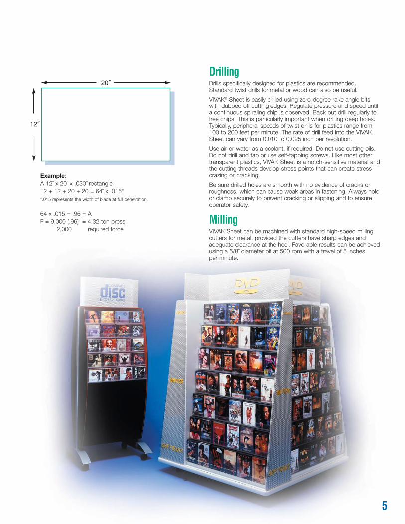
20˝
12˝
Example:A 12˝ x 20˝ x .030˝ rectangle12 + 12 + 20 + 20 = 64˝ x .015**.015 represents the width of blade at full penetration.
64 x .015 = .96 = AF = 9,000 (.96) = 4.32 ton press
2,000 required force
DrillingDrills specifically designed for plastics are recommended. Standard twist drills for metal or wood can also be useful.
VIVAK® Sheet is easily drilled using zero-degree rake angle bitswith dubbed off cutting edges. Regulate pressure and speed untila continuous spiraling chip is observed. Back out drill regularly tofree chips. This is particularly important when drilling deep holes.Typically, peripheral speeds of twist drills for plastics range from 100 to 200 feet per minute. The rate of drill feed into the VIVAKSheet can vary from 0.010 to 0.025 inch per revolution.
Use air or water as a coolant, if required. Do not use cutting oils.Do not drill and tap or use self-tapping screws. Like most othertransparent plastics, VIVAK Sheet is a notch-sensitive material andthe cutting threads develop stress points that can create stresscrazing or cracking.
Be sure drilled holes are smooth with no evidence of cracks orroughness, which can cause weak areas in fastening. Always holdor clamp securely to prevent cracking or slipping and to ensureoperator safety.
MillingVIVAK Sheet can be machined with standard high-speed millingcutters for metal, provided the cutters have sharp edges andadequate clearance at the heel. Favorable results can be achievedusing a 5/8˝ diameter bit at 500 rpm with a travel of 5 inches per minute.

6
Brake Forming and Cold BendingBrake forming and cold bending operations can be used to make simple bends and curved areas with VIVAK® Sheet.
Brake forming can be done on standard sheet metal brakes. Do not attempt to bend gauges over .080˝, because stress levels are too high and failure can occur.
VIVAK Sheet may be cold formed into circular shapes by observing the rule that the radius of curvature must be at least 100 times the material thickness. Example: .080˝ gauge = 8˝ radius(16˝ diameter circle).
Strip HeatingBecause of its low thermoforming temperature, VIVAK Sheet iseasy to strip heat and line bend.
Using a device similar to the illustration shown, regulate the heat to a temperature that allows VIVAK to reach 280°F. Thicker gaugeVIVAK Sheet requires a longer period of time to allow heat penetration.
ProcedureO Remove protective masking from area to be bent
O Regulate heat source to allow VIVAK Sheet to reach 280°F-320°F
O Place sheet over heat source at bend area
O Allow heat to soften material; time depends on gauge, 1/8˝ normally requires 2 minutes
O Remove sheet and make desired bend, and place in wood or fabric-covered aluminum fixture
O Allow bent part to cool in fixture
Strip Heating TroubleshootingProblem: Bubbles in bent areaPossible Cause: Too much heatSuggested Solution:1. Reduce temperatureProblem: WarpagePossible Cause: Part too wide for strip heating. Heating not uniform.Suggested Solution:1. Check for drafts2. Check heat source for uniformityPossible Cause: Cooling not uniformSuggested Solution:1. Check for drafts2. Cooling fixtures may be removing too much heat in an areaProblem: Mark offPossible Cause: Heater is contacting plasticSuggested Solution:1. Increase gap between heater and sheetPossible Cause: Transite is too hotSuggested Solution:1. Increase width of slot in transitePossible Cause: Masking not removed in wide enough areaSuggested Solution:1. Remove masking further away from heated area
FORMING
Helpful Hints• Try to reproduce the suggested steps accurately from part to part
• Avoid drafty rooms which can cause uneven heating and cooling
• Be sure to cover forming fixtures with soft fabric to avoid scratching VIVAK Sheet
• Overheating can cause bubbles along bend area
• Bending VIVAK Sheet when it is too cold results in a highly-stressed,weakened part
• Thicker gauges (over .125˝) may require heating on both sides by turning thesheet over periodically during the heating cycle. Always bend the sheet withheated side forming the outside radius.
Nichrome resistancewire (or Calrodtype heater)
Milled groove to accept Nichrome wire (approximately 1/16´´-1/8´´ belowsurface of VIVAK Sheet). Do not allow wire to contact sheet directly.
3/4´´ Transiteapprox. 6´´ wide
Rheostatfor temp.control
Heat Bending Device

7
Strip Heating Suppliers:FTM Plastic Welding, Inc. Craftics, Inc.6160 Cobblestone Road PO Box 91930Placerville, CA 95667 Albuquerque, NM 87199Tel: (530) 626-1986 Tel: (505) 338-0005
Typical Mold Materials Thermal Conductivity Properties
Heat Transfer K ValueMaterial Rate Factor BTU/HR/SF/F/FTAluminum 6190 130Steel 1238 26Aluminum filled epoxy 24-47 .52-.87Plaster of paris 8.29 .17Epoxy 6.24 .13Wood (maple) 4.48 .09
3.021´´
Mold3.00´´
Part
Mold Shrinkage
Helpful Hints• Keep the diameter of the holes small (approximately 1/64˝-1/32˝ diameter)
to avoid marking on the sheet. Long, thin slots may be designed for air evacuation in female tooling.
• Use vapor honed or fine sanded finishes• Avoid sharp corners to minimize stress• Avoid highly polished surfaces that can cause mark off• If mold temperature becomes too high during thermoforming runs, VIVAK Sheet
could stick to the mold. It is recommended that the mold temperature not exceed 140°F.
Mold Design continued on page 8 and 9
MoldsAlthough male molds are more suitable for vacuum forming ingeneral, other factors such as part size, finish, and shape must be considered in mold design. Choice of mold materials should be determined by considering the length of the production run.For optimum cost-effectiveness, use the least expensive materialthat will take the entire run.
It is evident that thermal transfer is much more efficient withaluminum than wood. Wood, however, can be utilized for short-run projects.
VIVAK Sheet tends to reproduce mold surface finish quite faithfully, even to the point of replicating wood grain in a smooth wood mold.
Sometimes it is desirable to reduce the polish on a steel oraluminum mold by utilizing a vapor hone or bead blast. This is dueto the fact that if the mold surface is too smooth, air entrapmentcan occur creating "mark off". For best results, use fine handsanding on the surfaces. Sanding provides tiny channels for air evacuation to prevent air entrapment. This may have to berepeated on long production runs, as the sanded finish smoothsout from extended use.
When constructing the mold, mold shrinkage should be a designconsideration. Shrinkage for VIVAK Sheet is .005˝-.007˝/in. Theheating/cooling cycle and the type of vacuum forming equipmentwill also influence results.
Mold DesignDraft Angles: Minimum 5°-7° or greater for ease of part removalfrom the mold.
Radii and Fillets: Use generous radii wherever possible for moreuniform walls and greater rigidity. On female tooling, usepermanent corner fillets.
Vacuum Holes: In order to form the sheet as rapidly as possible,use sufficient holes for fast evacuation of air from between thesheet and the mold. In female molds, use air evacuation holes atall deep draw areas, especially around the mold perimeter wherethe sheet will be drawn last.
ThermoformingVIVAK® Sheet offers deeper draws without the webbing oftenassociated with acrylic. It can be thermoformed on standardequipment. The most extensively used processes are vacuumforming, free blown forming, and line bending.
Forming EquipmentThe thermoforming machine should be capable of generating and maintaining sufficient vacuum pressure throughout thethermoforming cycle. A minimum of 20 in. Hg. throughout the entire vacuum cycle is required to retain part integrity.
Most commonly used vacuum forming machines with infraredheating elements perform well for VIVAK Sheet forming. Rotaryand shuttle designs with automatic or semiautomatic controls are most suitable. Key features of this type of equipment include:timer control accuracy, uniform heating sources, and sufficientvacuum power. Single-sided heating has proven effective forVIVAK Sheet in gauges up to .177˝. For thicknesses above .177˝,dual-sided heating ovens can be used for faster radiationpenetration and quicker cycle times.
HeatersInfrared cal rod, coiled nichrome, or ceramic heating elementsprovide the best heating sources. Uniform heating of the sheet is critical. Radiation absorption graphs for VIVAK Sheet areavailable. Matching the emissivity of the heating elements provides the most efficient heat penetration.
Mold Materials and Mold DesignVIVAK Sheet allows the use of a wide variety of mold materialsincluding: wood, filled and unfilled polyesters, epoxies, and metals.
Molds for vacuum forming need to take only 14 psi, so there islittle wear on the tooling with low pressure of the material againstthe mold surface.Use standard mold design practices and mold materials.

8
Heating CycleHeating VIVAK® Sheet for vacuum forming requires heatpenetration to achieve a 280°F to 320°F range. When VIVAKSheet reaches forming temperature, uniform "sag" occurs. Theamount of sag depends on the size and thickness of the sheet. A 12˝ x 12˝ x .060˝ sheet will sag approximately 1˝. A 36˝ x 36˝ x .177˝ sheet may sag 4˝-6˝ at the center. Once the uniformtemperature has been achieved, timers can accurately reproducethe condition, and part-to-part consistency can be maintained.
ProcedureO Sheet thicknesses up to .177˝ gauge can be heated from
one side. Above .177˝ gauge, two-sided heating is normallyrequired to significantly enhance productivity.
O Heat source is removed and heated sheet is forced over or into mold where vacuum is applied.
Shading or ScreeningShading is often used to balance out hot spots in an oven foruniform temperature. Shading may also be used to control the sag of VIVAK Sheet during heating.ProcedureO Use heavy-duty metal screening to shade the major portion
of the clamped sheet, leaving several inches along the edgesunshaded to compensate for cooler areas.
O Screens can be installed permanently or placed loosely abovethe Sheet, depending on how much shading is required.
Clamp HEATERSheet
Sheet
FemaleMold
WorkTable
le
Vacuum
Straight vacuum forming in a female mold is recommended for low-profile parts where deep draw is not a requirement.
Clamp HEATERSheet Sheet
MaleMold
WorkTable
le
Vacuum
Drape forming over a male mold usually results in better materialdistribution and depth-to-diameter draw ratios.
Clamp
HeatedSheet
Sheet
MaleMold
VacuumBox
Vacuum
VacuumVacuum forming with snap-back can reduce starting sheet size,aid material distribution, and minimize chill marks.
Clamp
HeatedSheet
Sheet
MaleMold
Mold
Vacuum AppliedAirEntering
Air-slip forming is similar to vacuum snap-back except that heatedsheet is billowed up and mold rises to meet it.
Clamp
HeatedSheet
Force
FemaleMold
Vacuum DrawsSheet Against Mold
Plug
Air BlowsSheet Up
Forming with billow plug is often used to produce thin-wall items with depth-to-diameter draw ratios up to 1.5:1.
Thermoforming TroubleshootingProblem Possible Cause Suggested SolutionPart weak or crazed • Forming temperature • Increase heat setting
too lowWebbing • Uneven Heat • Check for hot spots
in heaters• Mold spacing too close • Spacing between molds
in multiple mold should be 2˝ x height
• Vacuum rate too fast • Restrict vacuum Part sticks to mold • Mold too hot • Reduce mold temp
• Not enough draft angle • Increase draftMark off • Mold finish too smooth • Vapor hone or sand with
light finish sand paper
Pinholes on surface • Dust on sheet or mold • Blow off sheet andmold with air
Incomplete part detail • Insufficient vacuum • Check system for vacuum• Sheet too cold leaks; add vacuum holes
• Increase heat settingBubbles in sheet • Excessive heat • Reduce heat settingNon-uniform sag • Uneven heating • Check heaters
• Screen "hot" areasSheet pulls out of clamping • Sheet too cold to form • Heat sheet forframe during forming longer time period
ClampHeatedSheet
Sheet
Mold
WorkTable
le
Vacuum
ForcePlug
Thinning of material in deep-mold cavities can be overcomeby use of plug assists designed for fast penetration.
MOLD DESIGN CONTINUED
Helpful Hint• Throughout the vacuum forming process, it is imperative that dust and dirt
be controlled. VIVAK Sheet has a static charge that attracts foreign particleswhich can crate surface imperfections. Molds also attract dust particles andshould be cleaned to avoid creating surface defects.
Helpful Hints• Use slow heating. This is particularly important with heavier gauges
in order to prevent gradient heating.
•Allow heat to reach uniformity at the center of the sheet.
• The heating rate may be reduced by lowering the heat intensity or by moving the sheet farther away from the heaters.
Forming GuidelinesSheet Temperature:
Typical: 280°F-320°FMold Temperature: 130°F-140°F

Free Blown Billow Forming of DomeThis process is utilized for forming dome shapes from VIVAK®
Sheet. The procedures and equipment are the same as vacuumforming with the exception of the mold. Billow forming can bedone with positive air pressure (free blown) or negative pressure(vacuum).
ProcedureO Place VIVAK Sheet in clamping frame
of thermoforming machineO Heat sheet until uniform sag occurs
(280°F - 320°F)O Remove heat sourceO Lower pressure box to seal air
supply pressureO Apply air pressure. Initial air pressure
is high, and as dome is created, airpressure is reduced.
O When overall height is achieved,maintain positive air pressure untilpart cools
O Be sure air source is properly filteredand uniformly dispersed for evenformation of dome
O Utilize electric eye designs or micro-switches to assure consistent product
O When dome reaches electric eye, setheight. The eye controls air pressurethrough a solenoid valve to control cooling
O Remove and trim
Free Drawn Vacuum Dome FormingFollow steps involved in vacuum thermoforming.
ProcedureO Place sheet in clamping frame
of thermoforming machineO Heat sheet until uniform sag occurs
(280°F - 320°F)O Remove heat sourceO Apply vacuum seal box and apply
vacuum pressureO Use electric eye or microswitch
to assure consistency of depth of dome
O Retain small amount of vacuumpressure until dome sets up
O Remove and trim
Drape FormingSimple contours can be achieved by drape forming VIVAK® SheetProcedureThis method can be utilized to manufacture a part requiring a simple radius of curvature. Moldmaterial can be wood, fiberglass, or aluminum covered with felt.
O Bring to forming temperature ofabout 280°F-320°F in the oven
O Remove parts and immediately placeover a male mold covered with felt
Cylindrical FormingThis method is useful for short run projects that are not cost-effective using drape-form molds, or where cold-forming is not applicable (i.e., frameless curved parts).
ProcedureO Position stops until the desired diameter is achievedO Cold form VIVAK® Sheet into place between stopO Heat the VIVAK Sheet in curved position for the
normal cycle timeO Allow to cool, then remove from formNote: Do not overheat. Closely monitor procedure for best results.
Registration FormingVIVAK® Sheet is suitable for registration vacuum forming. Becausethe material is extruded, it is important to orient the sheet so thateach part is screened and formed in the same direction each time.Material should be special ordered for this application. Shrink testsindicate VIVAK Sheet in free form shrinks about 5% in thedirection of extrusion and 1% across the extrusion web.
9
Heat Source
MicroswitchElectric
Eye
Air Pressure
Sag
ClampFrame
Air Box
Air Inlet
VIVAKSheet
®
Thermoforming Machine Suppliers:Brown Machine330 North Ross StreetBeaverton, MI 48612Tel: (989) 435-7741
Plastic-Vac, Inc.214 Dalton AvenueCharlotte, NC 28206Tel: (800) 438-4139
Heat Source
ElectricEye
Apply Vacuum
Sag
ClampFrame
Vacuum Box
Vacuum Line
VIVAKSheet
®
VIVAK®
Pressure Frame
Mold
Felt Flocking Covering Mold
VIVAK®
Mold
Pressure Frame
Diameter
FeltCovering
WoodStops
Base

10
Adhesive Bonding of Five-Minute Cure One-Week CureVIVAK® LAP Shear No Gap No GapStrength1 psiMethyl ethyl ketone (MEK) 500 1,500Cyclohexanone 0 1,100Tetrahydrofuran (THF) 100 1,50042% Methyl ethyl ketone (MEK)42% Trichloroethylene 400 1,90016% Methylene chloride85% Methylene chloride12% Trichloroethylene 200 2,0003% Methyl ethyl ketone (MEK)MC-Bond NA NA“WELD-ON” #3 Cement 0 1,800“WELD-ON” #4 Cement 400 2,100
Adhesive Suppliers: Transfer Tape Suppliers:WELD-ON Cements: 3M/Industrial & TapeIPS Corporation Specialties Division17109 S. Main Street `3M Center, Bldg. 220-7E-01Gardena, CA 90248 St. Paul, MN 55144-1000Tel: (800) 421-2677 Tel: (800) 362-3550
(310) 898-3300Supplier for mini-extruder Saint-Gobainwelding equipment: 1 Sealant ParkColumbine International, Ltd. Granville, NY 128325441 Merchant Circle Tel: (518) 642-2200Placerville, CA 95667Tel: (800) 635-6693
columbineint.com
MC-BOND: Ultrasonic Welding Equipment:
Polysciences, Inc. Branson Ultrasonics Corp.400 Valley Rd. 41 Eagle RoadWarrington, PA 18976 Danbury, CT 06813Tel: (800) 523-2575 Tel: (203) 796-0400
BONDING/FASTENING
Helpful Hints
• Edges must be clean and free from dirt• Light sanding of factory polished surfaces will aid in adhesion• Surfaces should be smooth and properly aligned• Recommended solvents are WELD-ON #3, WELD-ON #4, WELD-ON #7, (no edge
bonds) and MC-Bond• If joint whitening occurs, it may be caused by excessive moisture. Several techniques
reduce whitening• Fabricate in a climate-controlled area with low relative humidity• The addition of 10% glacial acetic acid in the solvent reduces whitening• Thickening the solvent with resin or sawdust promotes slower curing and reduces
whitening• Joint cure time is somewhat longer than acrylic. Be sure to retain fixture pressure until
the joint is solid• Success has been reported adhering small acrylic components to VIVAK Sheet
using products such as MC-Bond and WELD-ON #55.
1For the purpose of this evaluation, all bonds were 1/2˝ x 1/4˝ lap-type bondsbetween sections of VIVAK tensile bars. Bonds were tested using standard tensilestrength test apparatus and a cross-head speed of 2˝ per minute. All values are 3-test averages to the nearest 100 psi. Values less than 50 psi are listed as “0”.
Solvent BondingSince VIVAK® has excellent chemical resistance, it is important to use proper solvent bondingtechniques. Solvent bonding will reduce the impact performance of the bonded edge of mostmaterials. When the highest possible impact performance is esential, use flexible adhesivebonding.
Many applications for VIVAK® Sheet involve fabrication of sheets to construct three-dimensional shapes. The most popular methodis to solvent bond. VIVAK solvent bonding can be achieved usingmethods employed in fabricating other thermoplastics such asacrylic. The two most common methods are needle-typeapplicator capillary action and edge dipping. Both methods rely on smooth edge preparation, pressure, and curing.Note: Use extreme caution when working with solvents. Adequate ventilation isessential. Control exposure levels according to OSHA guidelines. Obtain MaterialSafety Data Sheets from the solvent manufacturer.
ProcedureO Smaller items with flat surfaces can be bonded by placing
the pieces together and applying the solvent along the edgesusing a needle applicator or hypodermic syringe. Make sure the solvent flows along the entire joint
O For bonding larger items, immerse the surfaces to be joined inthe solvent until the material is softened
O Apply light pressure and hold until bond is setO Avoid solvent pooling in the joint which can cause joint whitening
and stress crazing
Transfer Tape BondingAchieving a strong solvent bond using thin-gauge thermoplastics isextremely difficult due to the reduced size of the bond area.However, structural bonding of thin-gauge VIVAK® Sheet can beaccomplished by utilizing acrylic based transfer tapes along withslight design modifications.
Procedure
O Bend a small return on the appropriate part to be fastened, approximately the width of the transfer tape
O Clean tape contact areas with 50/50 isopropyl alcohol-water mixture
O Apply transfer tape to the returnO Remove masking and press the part into place
WeldingWhile mechanical fastening and solvent bonding are the mostoften recommended methods for joining plastics, anotheralternative is welding. Ultrasonic spot welding has proven to be anappropriate method. Contact manufacturers of ultrasonic weldingequipment for recommendations on section and joint design. Miniextruder welding can also be used to bond VIVAK sheet. Bothmethods can be used while maintaining FDA approval.
Mechanical FasteningSelf-closing rivets and machine screws may be used to join VIVAK Sheet parts, if proper consideration is given to the installation. Use oversized holes at least 1/64˝ larger than the fastener.
A cushion-type washershould be used to avoidlocalized stress on VIVAKSheet. Use plastic oraluminum fasteners.Mechanical fastening willproduce a stronger partthan solvent bonded partsand allows for easierdisassembly and cleaning.

11
FINISHING
Helpful Hints• After screening, separate sheets on a drying rack
until ink is fully cured
• Do not pack sheets for shipment until inks are dry
• VIVAK Sheet is not compatible with UV cure screen printing. Ultraviolet curing lamps tend to attack VIVAK Sheet, and some loss in physical properties occurs.
Paint Suppliers: Screen Print Suppliers:Spraylat Corporation Nor-Cote International, Inc.716 South Columbus Ave. 506 Lafayette Ave.Mt. Vernon, NY 10550 Crawfordsville, IN 47933Tel: (914) 699-3030 Tel: (800) 488-9180
Red Spot Paint & Varnish Co. Kolorcure1107 E. Lousiana St. 1180 Lyon RoadEvansville, IN 47711 Batavia, IL 60510Tel: (812) 428-9100 Tel: (630) 879-9050
AKZO-Nobel Coates Screen Inc.5555 Spalding Drive 180 East Union AvenueNorcross, GA 30092 East Rutherford, NJ 07073Tel: (800) 233-2303 Tel: (201) 933-6100
Rohm and Haas NazDar2700 East 170th Street 8501 Hedge Lane TerraceLansing, IL 60438 Shawnee, KS 66227Tel: (708) 474-7000 Tel: (800) 767-9942
SandingVIVAK® Sheet can be sanded using both wet and dry techniques.Gumming can result from dry sanding. Wet sanding produces a smooth finish. In both instances, the part will require furtherfinishing in order to restore its high gloss.
VIVAK Sheet can also be buffed using a 2-wheel system. The first wheel uses a buffing compound to remove shallowscratches. The second buffing wheel is used for restoring the gloss.
Jointing-PlaningA standard woodworking jointer-planer is an excellent edgefinishing machine for VIVAK Sheet. Blades must be carbide orhigh-speed steel. Avoid removal of too much stock on each pass.1/64˝ or less stock removal normally yields the cleanest edge.Trying to remove too much material results in a rough edge orshattering of the sheet.
If smoother edges are required, wet sanding with fine gritsandpaper is recommended.
Flame PolishingWhen flame polishing VIVAK Sheet use a standard butane orpropane torch. Dress the edges by sanding or jointing to removethe deep tool or saw marks. After torch ignition, be sure to turndown oxygen levels to the lowest possible workable point whilestill maintaining flame. Pay close attention to controlling thedistance between the sheet and the heat source. Withoutadequate control in these areas, surface whitening or excessivematerial flow may occur.Note: As with acrylic, flame polishing VIVAK Sheet can cause long-term edgecracking. However, with continued practice and by using proper techniques, excellent results can be achieved in flame polishing VIVAK Sheet.
Solvent PolishingIn order to improve the look of saw-cut edges, begin by sandingthe edges smooth. For smoother, glossy edges, consider solventpolishing with MEK or methylene dichloride. To prevent humidityblush after drying, it may be necessary to add a small amount of a slow-drying component such as diacetone alcohol or glacial acetic acid. Since VIVAK Sheet has such good chemicalresistance properties, keep in mind that solvent polishing cannotbe expected to totally eliminate sand marks from the sheet edge.Note: Use extreme caution when working with solvents. Adequate ventilation isessential. Control exposure levels according to OSHA guidelines. Obtain MaterialSafety Data Sheets for the solvent manufacturer.
Hot StampingVIVAK Sheet is easily decorated by hot stamping. Normaloperating conditions are: head (die) temperatures 375°F with 60psi pressure, with dwell time 2-3 seconds.
Contact foil manufacturer for recommended applicationguidelines.
Hot Stamping Foil Suppliers:ITW Crown Roll Leaf, Inc.5 Malcolm Hoyt Dr. 91 Illinois Ave.Newburyport, MA 01950 Patterson, NJ 07503Tel: (978) 462-7300 Tel: (800) 631-3831
Screen PrintingVIVAK Sheet can be printed with conventional printing equipment.Since the ink does not penetrate plastic, special printing inks arenecessary. Abrasion can be minimized by applying a light coat ofclear lacquer over the printing. Consider each application individ-ually to decide on the best ink for the specific job. Consult with inkmanufacturers for best results.
ProcedureO VIVAK Sheet provides
an excellent medium for signs, when usingstandard silk screeningequipment with screens of varying mesh (8x to 16x)regulating the amountof ink coverage
O Be careful not toexceed the heatdistortion temperatureof 164°F during the cure process
O As with all thermo-plastics, it is very important to be sure the sheet is clean and free from dust and dirt prior to screening. Useionized air to clean dust or pre-rinse withalcohol and a soft, nonabrasive cloth

©Copyright, Sheffield Plastics Inc., 2003 Rev. 12/04 Printed in USAVIVAK® is a registered trademark of Sheffield Plastics Inc.
VIVAK FabGuide 12/04
TYPICAL PHYSICAL PROPERTIES OF VIVAK SHEETProperty VIVAK® Sheet Units Test MethodGeneralSpecific Gravity 1.27 - ASTM D-792Water Absorption after 24 hrs. 0.2 % ASTM D-570ThermalDeflection Temperature @ 264 psi 157 °F ASTM D-648Deflection Temperature @ 66 psi 164 °F ASTM D-648Coefficient of Thermal Expansion 3.8 in/in/°F x 10-5 ASTM D-696Flammability ≥ .060˝ HB - UL 94Glass Transition Temperature 178 °F -Forming Temperature 280°-320° °F -MechanicalTensile Strength, Ultimate .125˝ 7,700 psi ASTM D-638Tensile Modulus .125˝ 320,000 psi ASTM D-638Flexural Strength .125˝ 11,200 psi ASTM D-790Flexural Modulus .125˝ 310,000 psi ASTM D-790Izod Impact Notched .125˝ at 73° 1.7 ft. lb/in ASTM D-256Izod Impact Notched .125˝ at 32° 1.2 ft. lb/in ASTM D-256Drop Dart Impact .250˝ at 73° 53 ft. lbs ASTM D-3763Rockwell Hardness 115 R Scale ASTM D-785OpticalLight Transmission 86 % ASTM D-1003Refractive Index 1.57 - ASTM D-542Haze 1.0 % ASTM D-1003
PERFORMANCEVIVAK® Sheet combines an excellent balance of properties for a wide range of fabricated products.
Application Limitations
VIVAK Sheet, like any thermoplastic, has itsperformance limitations under specific conditions and in particular environments. When selecting a product, the environment and the conditions under which the product is to be used should beconsidered by the user.
For Example:
O VIVAK Sheet's heat resistance of 164°F precludesits use in heat generating applications when typicaltemperatures exceed 164°F.
O While it is a common choice for interior signage, its limited UV resistance eliminates it as a potentialchoice for long-term outdoor applications. Forexterior use, ask for information on VIVAK Sheet UV.
O VIVAK Sheet's good chemical resistance makes it ideally suited for harsh industrial environments.However, this chemical resistance may meanlonger fixturing time when using solvent based adhesives.
Technical Assistance
Contact the Sheffield Technical Services Group onquestions regarding specific applications or materialrecommendations.
Impact StrengthFalling Dart @ 73°FASTM D-5420 @ .125˝ Acrylic Polycarbonate VIVAK® Sheet10 in/lbs. Failed No break No break100 in/lbs. Failed No break No break300 in/lbs. Failed No break No breakHeat Distortion @ 264 psi 190°F 270°F 157°F
@ 66 psi 280°F 164°FGamma Stability Poor Fair ExcellentChemical Resistance Poor Fair Good
Performance ComparisonCompare VIVAK Sheet's performance for interior fabricated and formed applications. It delivers an optimum balance of performance and economy.
Material AvailabilityMaterials Gauge Range Colors Patterns SizesVIVAK® Sheet .020˝-.375˝ Standard: Standard: Standard:
• Clear • Polished 2 Sides • 48˝ x 96˝Custom: • 60˝ x 96˝• Tints Custom:• Opaques • Available
Sheffield will not be responsible for the use of this informationrelative to actual application. Users must make their own determi-nation of its suitability for their specific use. No warranty is madefor the fitness of any product, and nothing herein waives any ofthe seller’s condition of sales.
For Additional Information Please Contact...Sheffield Plastics Inc.Customer Service DepartmentPhone: 800-254-1707FAX: 800-457-3553www.sheffieldplastics.com
119 Salisbury RoadSheffield, MA 01257800-254-1707Fax: 800-457-3553www.sheffieldplastics.comE-mail: [email protected]