vlt® 2800/6000 modbus rtufiles.danfoss.com/download/drives/doc_a_1_mg10s122.pdfvlt® serie 2800 and...
TRANSCRIPT
VLT® Serie 2800 and VLT® Serie 6000 Modbus RTU
å Contents
Overview ............................................................................................................. 5Introduction ............................................................................................................ 5About This Manual ................................................................................................. 5Assumptions .......................................................................................................... 5What You Should Already Know ............................................................................. 5Modbus RTU Overview .......................................................................................... 5VLT 2800 and VLT 6000 with Modbus RTU ............................................................ 6
Installation and Setup .................................................................................. 7Network Connection ............................................................................................. 7Hardware Setup VLT 2800 ..................................................................................... 8Hardware Setup VLT 6000 ..................................................................................... 8EMC Precautions ................................................................................................... 8
Modbus RTU Programming ....................................................................... 9VLT 2800 Parameter Settings for Modbus Communication ..................................... 9VLT 6000 Parameter Settings for Modbus Communication ..................................... 11
Network Configuration ................................................................................. 13Remote Terminal Unit ............................................................................................. 13Modbus RTU Message Framing Structure .............................................................. 13
Parameter Handling ....................................................................................... 16Parameter Handling ................................................................................................ 16Translation from Modbus RTU Protocol to FC Protocol ........................................... 16Register Maps VLT 2800 ........................................................................................ 17Register Maps VLT 6000 ........................................................................................ 18Process Data ......................................................................................................... 19Status Coil Maps .................................................................................................... 19Control Word Bit Descriptions for VLT 2800 ............................................................ 19Status Word Bit Description for VLT 2800 ............................................................... 21Control Word Bit Descriptions VLT 6000 ................................................................. 23Status Word Bit Descriptions VLT 6000 .................................................................. 24Serial communication reference .............................................................................. 25Present output frequency ....................................................................................... 26
Supported Modbus RTU Function Codes ......................................... 27
Exception Codes ............................................................................................. 31Exception Code Tables .......................................................................................... 31
Appendix A - Examples ............................................................................... 32
MG.10.S1.22 - VLT is a registered Danfoss trademark 1
VLT® Serie 2800 and VLT® Serie 6000 Modbus RTU
åSoftware Version VLT 2800 and VLT 6000
195NA009.17
VLT 2800 Series
Operating instructionsSoftware version: 2.8x
These operating instructions can be used for all VLT 2800Series frequency converters with software version 2.8x.The software version number can be seen from parameter640 Software version no.
175Z
A69
1.13
VLT 6000 HVAC
Operating InstructionsSoftware version: 2.6x
These Operating Instructions can be used for all VLT 6000HVAC frequency converters with software version 2.6x.The software version number can be seen from parameter624.
MG.10.S1.22 - VLT is a registered Danfoss trademark2
VLT® Serie 2800 and VLT® Serie 6000 Modbus RTU
Saf
ety
- M
odbu
sR
TU
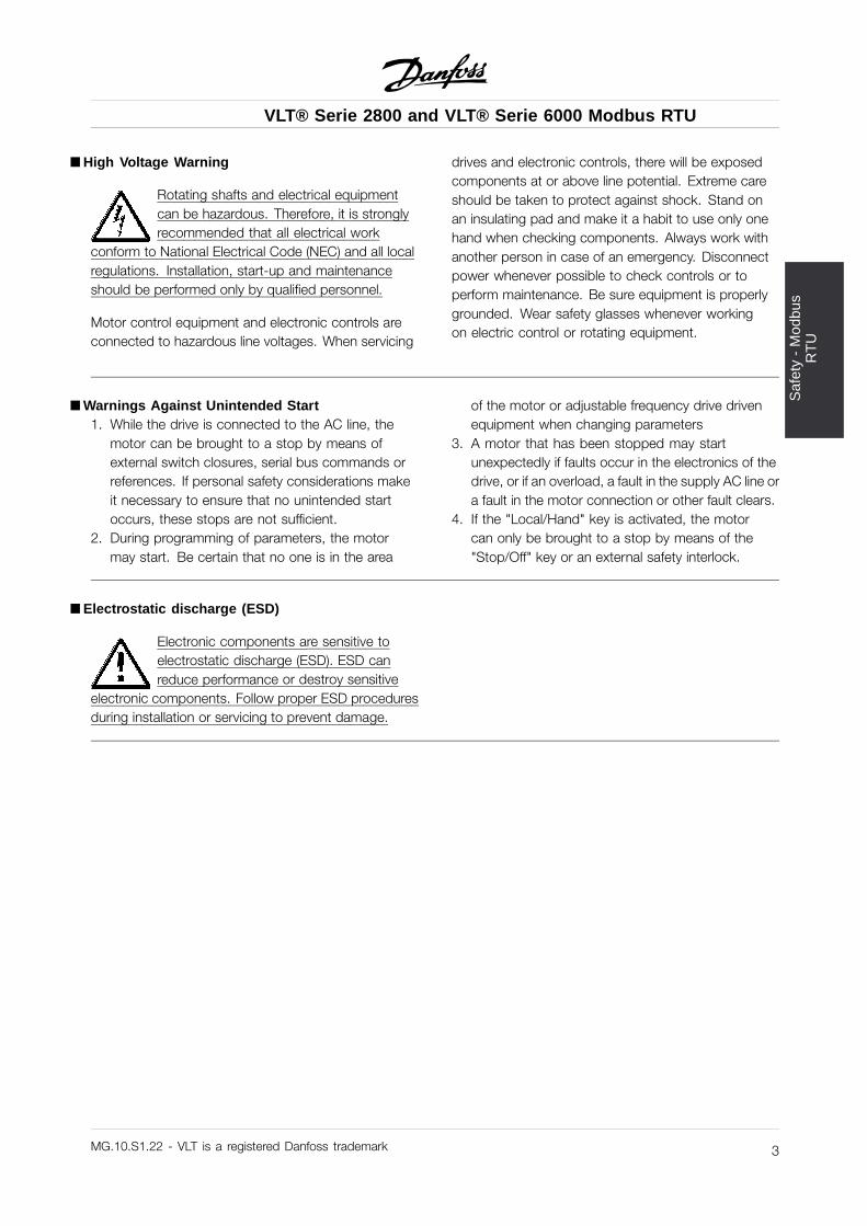
åHigh Voltage Warning
Rotating shafts and electrical equipmentcan be hazardous. Therefore, it is stronglyrecommended that all electrical work
conform to National Electrical Code (NEC) and all localregulations. Installation, start-up and maintenanceshould be performed only by qualified personnel.
Motor control equipment and electronic controls areconnected to hazardous line voltages. When servicing
drives and electronic controls, there will be exposedcomponents at or above line potential. Extreme careshould be taken to protect against shock. Stand onan insulating pad and make it a habit to use only onehand when checking components. Always work withanother person in case of an emergency. Disconnectpower whenever possible to check controls or toperform maintenance. Be sure equipment is properlygrounded. Wear safety glasses whenever workingon electric control or rotating equipment.
åWarnings Against Unintended Start1. While the drive is connected to the AC line, the
motor can be brought to a stop by means ofexternal switch closures, serial bus commands orreferences. If personal safety considerations makeit necessary to ensure that no unintended startoccurs, these stops are not sufficient.
2. During programming of parameters, the motormay start. Be certain that no one is in the area
of the motor or adjustable frequency drive drivenequipment when changing parameters
3. A motor that has been stopped may startunexpectedly if faults occur in the electronics of thedrive, or if an overload, a fault in the supply AC line ora fault in the motor connection or other fault clears.
4. If the "Local/Hand" key is activated, the motorcan only be brought to a stop by means of the"Stop/Off" key or an external safety interlock.
åElectrostatic discharge (ESD)
Electronic components are sensitive toelectrostatic discharge (ESD). ESD canreduce performance or destroy sensitive
electronic components. Follow proper ESD proceduresduring installation or servicing to prevent damage.
MG.10.S1.22 - VLT is a registered Danfoss trademark 3
VLT® Serie 2800 and VLT® Serie 6000 Modbus RTU
195NA139.10
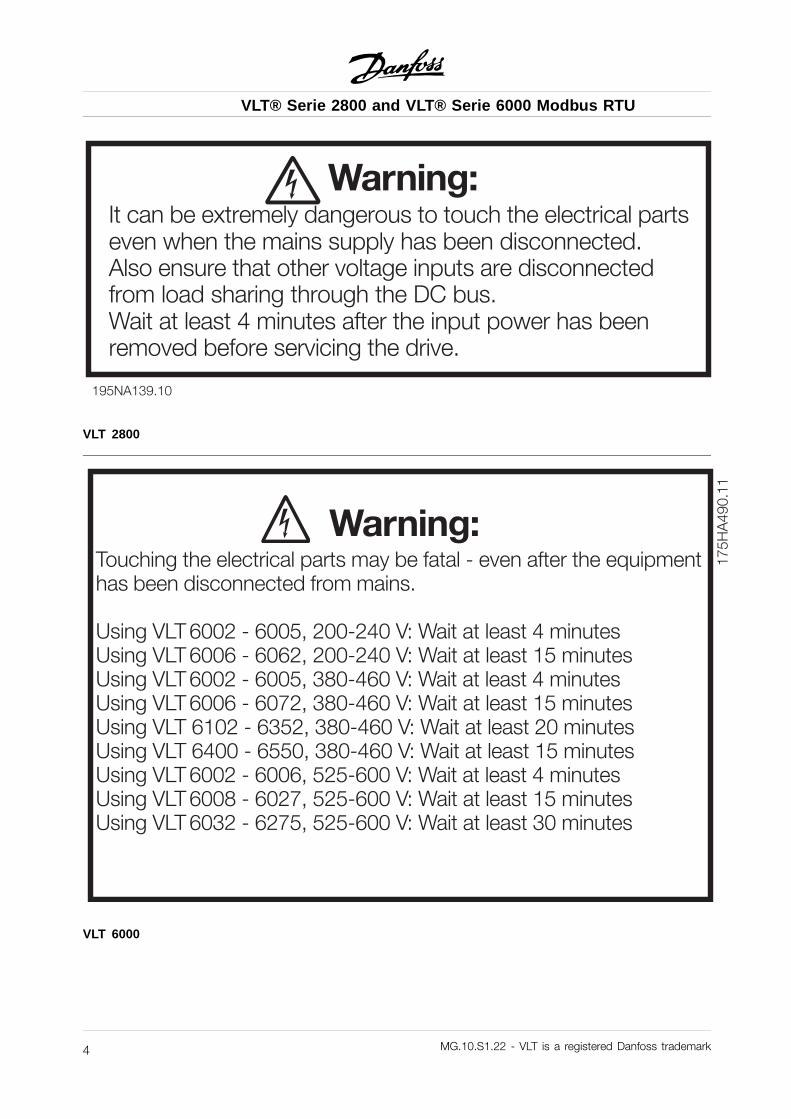
Warning:It can be extremely dangerous to touch the electrical partseven when the mains supply has been disconnected.Also ensure that other voltage inputs are disconnectedfrom load sharing through the DC bus.Wait at least 4 minutes after the input power has beenremoved before servicing the drive.
VLT 2800
175H
A49
0.11
Warning:Touching the electrical parts may be fatal - even after the equipmenthas been disconnected from mains.
Using VLT 6002 - 6005, 200-240 V: Wait at least 4 minutesUsing VLT 6006 - 6062, 200-240 V: Wait at least 15 minutesUsing VLT 6002 - 6005, 380-460 V: Wait at least 4 minutesUsing VLT 6006 - 6072, 380-460 V: Wait at least 15 minutesUsing VLT 6102 - 6352, 380-460 V: Wait at least 20 minutesUsing VLT 6400 - 6550, 380-460 V: Wait at least 15 minutesUsing VLT 6002 - 6006, 525-600 V: Wait at least 4 minutesUsing VLT 6008 - 6027, 525-600 V: Wait at least 15 minutesUsing VLT 6032 - 6275, 525-600 V: Wait at least 30 minutes
VLT 6000
MG.10.S1.22 - VLT is a registered Danfoss trademark4
VLT® Serie 2800 and VLT® Serie 6000 Modbus RTU
Ove
rvie
w
åOverview
å IntroductionThese operating instructions provide comprehensiveinstructions on the installation and set up of theModbus RTU for the VLT® 2800 and the VLT® 6000Adjustable Frequency Drive to communicateover a Modbus network.
For specific information on installation andoperation of the drive, refer to the VLT 2800Instruction Manual, MG.28.AX.YY / VLT 6000Instruction Manual, MG.60.AX.YY.
åAbout This ManualThese operating instructions are intended to be used forboth instruction and reference. It only briefly touches onthe basics of the Modbus protocol whenever necessaryto gain an understanding of the Modbus RTU.
These operating instructions are also intended toserve as a guideline when you specify and optimizeyour communication system. Even if you are anexperienced Modbus programmer, it is suggestedthat you read these operating instructions in itsentirety before you start programming since importantinformation can be found in all sections.
åAssumptionsThis Instruction Manual assumes that you have acontroller that supports the interfaces in this documentand that all the requirements stipulated in the controller,as well as the adjustable frequency drive, are strictlyobserved, along with all limitations therein.
åWhat You Should Already KnowThe Modbus RTU is designed to communicate with anycontroller that supports the interfaces defined in thisdocument. It is assumed that you have full knowledgeof the capabilities and limitations of the controller.
åModbus RTU OverviewModbus RTU (Remote Terminal Unit) protocol definesa message structure that controllers will recognize
and use, regardless of the type of physical networksover which they communicate. It describes theprocess a controller uses to request access to anotherdevice, how it will respond to requests from theother devices, and how errors will be detected andreported. It establishes a common format for thelayout and contents of message fields.
During communications on a Modbus RTU network,the protocol determines how each controller will knowits device address, recognize a message addressedto it, determine the kind of action to be taken, andextract any data or other information contained inthe message. If a reply is required, the controller willconstruct the reply message and send it.
Controllers communicate using a master-slavetechnique in which only one device (the master) caninitiate transactions (called queries). The other devices(slaves) respond by supplying the requested data to themaster, or by taking the action requested in the query.
The master can address individual slaves, or caninitiate a broadcast message to all slaves. Slavesreturn a message (called a response) to queries thatare addressed to them individually. Responses are notreturned to broadcast queries from the master.
The Modbus RTU protocol establishes the formatfor the master’s query by placing into it the device(or broadcast) address, a function code definingthe requested action, any data to be sent, and anerror-checking field. The slave’s response messageis also constructed using Modbus protocol. Itcontains fields confirming the action taken, any datato be returned, and an error-checking field. If anerror occurred in receipt of the message, or if theslave is unable to perform the requested action,the slave will construct an error message and sendit in response or a timeout will occur.
MG.10.S1.22 - VLT is a registered Danfoss trademark 5
VLT® Serie 2800 and VLT® Serie 6000 Modbus RTU
åVLT 2800 and VLT 6000 with Modbus RTUThe adjustable frequency drive communicates inModbus RTU format over an EIA-485 (formerlyRS-485) network. Modbus RTU allows access to thedrive’s Control Word and Bus Reference.
The Control Word allows the Modbus master to controlseveral important functions of the drive:• Start• Stop the drive in several ways:
Coast stopQuick stopDC Brake stopNormal (ramp) stop
• Reset after a fault trip• Run at a variety of preset speeds• Run in reverse• Change the active setup• Control the drive’s two built-in relays
The Bus Reference is commonly used for speed control.
It is also possible to access the parameters, readtheir values, and, where possible, write values tothem. This permits a range of control possibilities,including controlling the drive’s setpoint when itsinternal PID controller is used.
MG.10.S1.22 - VLT is a registered Danfoss trademark6
VLT® Serie 2800 and VLT® Serie 6000 Modbus RTU
Inst
alla
tion
and
Set
up
å Installation and Setup
Modbus RTU is a transmission protocol developed forprocess control systems. The Modbus standard doesnot specify the physical interface for the protocol i.e.a number of different interfaces can be chosen.The Modbus RTU protocol is based on the build-inRS-485 (EIA-485) interface.RS-485 is a two-wire bus-interface that allowsmulti-drop network topology i.e. nodes canbe connected as a bus, or via drop cablesfrom a common trunk line.A total number of 32 nodes can be connected toone Modbus RTU network segment, and a total of247 nodes in a network are supported.Network segments are divided with repeaters.Please note that each repeater counts for a nodein each segment it’s installed.Every node connected to the same network must havean unique nodes address, across all segments.
Every segment must be terminated in both ends, eitherwith the termination switches (switch 2 & 3) of the VLT6000 or with a biased termination resistor network.
For bus-cabling always use cable of screenedtwisted pair type (STP), and make sure to followgood common installation practice.Make sure the screen of the Modbus RTU cable mustalways be connected to ground at all nodes.
It is very important to have a low impedance groundconnection of the screen, also at high frequencies.This can be obtained by connecting a large surfaceof the screen to ground, for example by means ofa cable clamp or a conductive cable gland.Particularly in installation where there is longcable lengths, it can be necessary to applypotential equalizing cables to ensure same groundpotential throughout the network.To prevent impedance mismatch, always use cableof same type across the entire network.When connecting a motor to the frequency converter,make sure always to use screened motor cable.
Adress range:1 - 247
Baud Rate:300 - 9600 bps
Cable:Screened twisted pair (STP)Impedance: 120 Ohm
Cable length:Max. 1200 m (including drop lines)Max. 500 m station-to-station
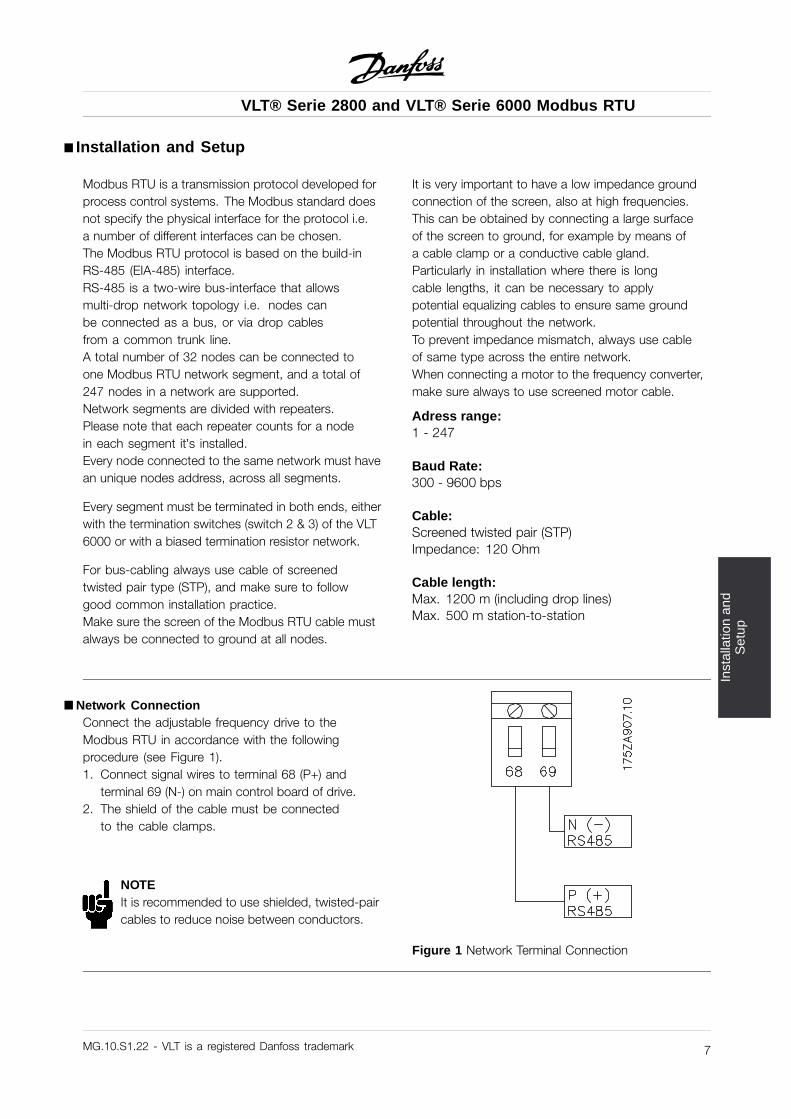
åNetwork ConnectionConnect the adjustable frequency drive to theModbus RTU in accordance with the followingprocedure (see Figure 1).1. Connect signal wires to terminal 68 (P+) and
terminal 69 (N-) on main control board of drive.2. The shield of the cable must be connected
to the cable clamps.
NOTEIt is recommended to use shielded, twisted-paircables to reduce noise between conductors.
Figure 1 Network Terminal Connection
MG.10.S1.22 - VLT is a registered Danfoss trademark 7
VLT® Serie 2800 and VLT® Serie 6000 Modbus RTU
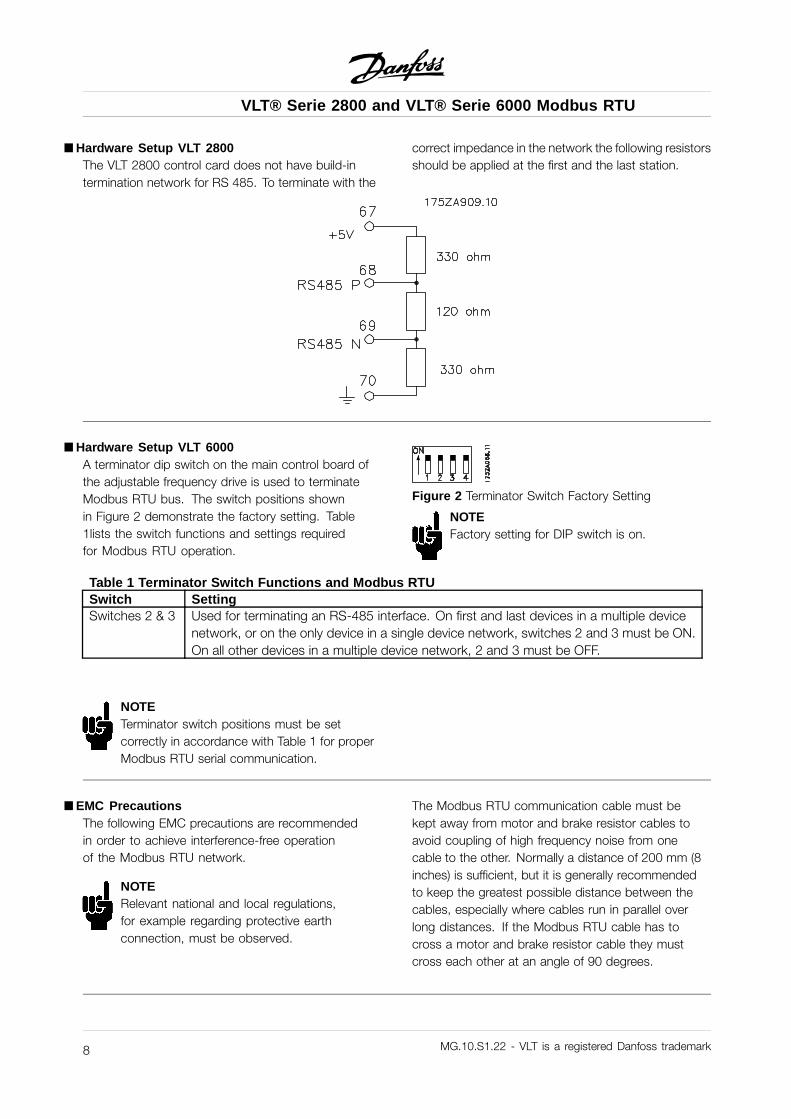
åHardware Setup VLT 2800The VLT 2800 control card does not have build-intermination network for RS 485. To terminate with the
correct impedance in the network the following resistorsshould be applied at the first and the last station.
åHardware Setup VLT 6000A terminator dip switch on the main control board ofthe adjustable frequency drive is used to terminateModbus RTU bus. The switch positions shownin Figure 2 demonstrate the factory setting. Table1lists the switch functions and settings requiredfor Modbus RTU operation.
Figure 2 Terminator Switch Factory Setting
NOTEFactory setting for DIP switch is on.
Table 1 Terminator Switch Functions and Modbus RTUSwitch SettingSwitches 2 & 3 Used for terminating an RS-485 interface. On first and last devices in a multiple device
network, or on the only device in a single device network, switches 2 and 3 must be ON.On all other devices in a multiple device network, 2 and 3 must be OFF.
NOTETerminator switch positions must be setcorrectly in accordance with Table 1 for properModbus RTU serial communication.
åEMC PrecautionsThe following EMC precautions are recommendedin order to achieve interference-free operationof the Modbus RTU network.
NOTERelevant national and local regulations,for example regarding protective earthconnection, must be observed.
The Modbus RTU communication cable must bekept away from motor and brake resistor cables toavoid coupling of high frequency noise from onecable to the other. Normally a distance of 200 mm (8inches) is sufficient, but it is generally recommendedto keep the greatest possible distance between thecables, especially where cables run in parallel overlong distances. If the Modbus RTU cable has tocross a motor and brake resistor cable they mustcross each other at an angle of 90 degrees.
MG.10.S1.22 - VLT is a registered Danfoss trademark8
VLT® Serie 2800 and VLT® Serie 6000 Modbus RTU
Mod
bus
RT
UP
rogr
amm
ing
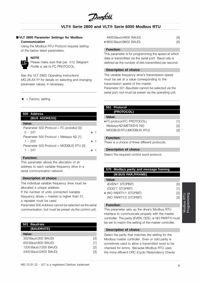
åVLT 2800 Parameter Settings for ModbusCommunicationUsing the Modbus RTU Protocol requires settingof the below listed parameters.
NOTEPlease make sure that par. 512 TelegramProfile is set to FC PROTOCOL.
See the VLT 2800 Operating InstructionsMG.28.AX.YY for details on selecting and changingparameter values, if necessary.
= Factory setting
500 Address(BUS ADDRESS)
Value:Parameter 500 Protocol = FC protolkol [0]0 - 247 j 1
Parameter 500 Protocol = Metasys N2 [1]1 - 255 j 1
Parameter 500 Protocol = MODBUS RTU [3]1 - 247 j 1
Function:This parameter allows the allocation of anaddress to each variable frequency drive in aserial communication network.
Description of choice:
The individual variable frequency drive must beallocated a unique address.If the number of units connected (variablefrequency drives + master) is higher than 31,a repeater must be used.Parameter 500 Address cannot be selected via the serialcommunication, but must be preset via the control unit.
501 Baudrate(BAUDRATE)
Value:300 Baud (300 BAUD) [0]600 Baud (600 BAUD) [1]1200 Baud (1200 BAUD) [2]2400 Baud (2400 BAUD) [3]
4800 Baud (4800 BAUD) [4]j9600 Baud (9600 BAUD) [5]
Function:This parameter is for programming the speed at whichdata is transmitted via the serial port. Baud rate isdefined as the number of bits transmitted per second.
Description of choice:
The variable frequency drive’s transmission speedmust be set at a value corresponding to thetransmission speed of the master.Parameter 501 Baudrate cannot be selected via theserial port, but must be preset via the operating unit.
561 Protocol(PROTOCOL)
Value:jFC protocol (FC PROTOCOL) [1]
Metasys N2 (METASYS N2) [2]MODBUS RTU (MODBUS RTU) [3]
Function:There is a choice of three different protocols.
Description of choice:
Select the required control word protocol.
570 Modbus parity and message framing
(M.BUS PAR./FRAME)
Value:(EVEN/1 STOPBIT) [0](ODD/1 STOPBIT) [1]
j (NO PARITY/1 STOPBIT) [2](NO PARITY/2 STOPBIT) [3]
Function:This parameter sets up the drive’s Modbus RTUinterface to communicate properly with the mastercontroller. The parity (EVEN, ODD, or NO PARITY) mustbe set to match the setting of the master controller.
Description of choice:
Select the parity that matches the setting for theModbus master controller. Even or odd parity issometimes used to allow a transmitted word to bechecked for errors. Because Modbus RTU usesthe more efficient CRC (Cyclic Redundancy Check)
MG.10.S1.22 - VLT is a registered Danfoss trademark 9
VLT® Serie 2800 and VLT® Serie 6000 Modbus RTU
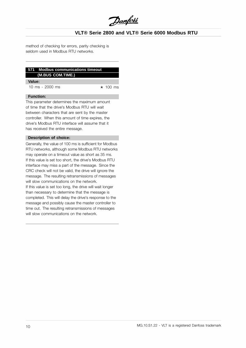
method of checking for errors, parity checking isseldom used in Modbus RTU networks.
571 Modbus communications timeout(M.BUS COM.TIME.)
Value:10 ms - 2000 ms j 100 ms
Function:This parameter determines the maximum amountof time that the drive’s Modbus RTU will waitbetween characters that are sent by the mastercontroller. When this amount of time expires, thedrive’s Modbus RTU interface will assume that ithas received the entire message.
Description of choice:
Generally, the value of 100 ms is sufficient for ModbusRTU networks, although some Modbus RTU networksmay operate on a timeout value as short as 35 ms.If this value is set too short, the drive’s Modbus RTUinterface may miss a part of the message. Since theCRC check will not be valid, the drive will ignore themessage. The resulting retransmissions of messageswill slow communications on the network.If this value is set too long, the drive will wait longerthan necessary to determine that the message iscompleted. This will delay the drive’s response to themessage and possibly cause the master controller totime out. The resulting retransmissions of messageswill slow communications on the network.
MG.10.S1.22 - VLT is a registered Danfoss trademark10
VLT® Serie 2800 and VLT® Serie 6000 Modbus RTU
Mod
bus
RT
UP
rogr
amm
ing
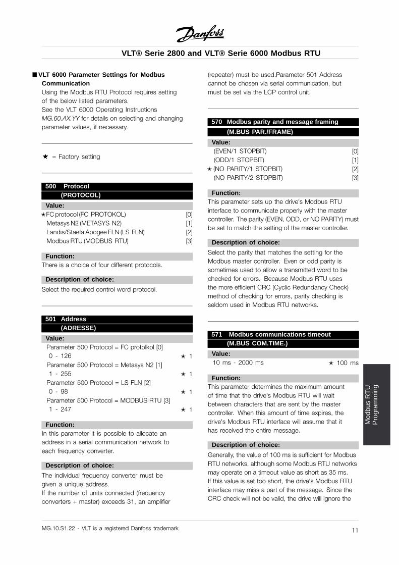
åVLT 6000 Parameter Settings for ModbusCommunicationUsing the Modbus RTU Protocol requires settingof the below listed parameters.See the VLT 6000 Operating InstructionsMG.60.AX.YY for details on selecting and changingparameter values, if necessary.
= Factory setting
500 Protocol(PROTOCOL)
Value:jFC protocol (FC PROTOKOL) [0]
Metasys N2 (METASYS N2) [1]Landis/Staefa Apogee FLN (LS FLN) [2]Modbus RTU (MODBUS RTU) [3]
Function:There is a choice of four different protocols.
Description of choice:
Select the required control word protocol.
501 Address(ADRESSE)
Value:Parameter 500 Protocol = FC protolkol [0]0 - 126 j 1
Parameter 500 Protocol = Metasys N2 [1]1 - 255 j 1
Parameter 500 Protocol = LS FLN [2]0 - 98 j 1
Parameter 500 Protocol = MODBUS RTU [3]1 - 247 j 1
Function:In this parameter it is possible to allocate anaddress in a serial communication network toeach frequency converter.
Description of choice:
The individual frequency converter must begiven a unique address.If the number of units connected (frequencyconverters + master) exceeds 31, an amplifier
(repeater) must be used.Parameter 501 Addresscannot be chosen via serial communication, butmust be set via the LCP control unit.
570 Modbus parity and message framing
(M.BUS PAR./FRAME)
Value:(EVEN/1 STOPBIT) [0](ODD/1 STOPBIT) [1]
j (NO PARITY/1 STOPBIT) [2](NO PARITY/2 STOPBIT) [3]
Function:This parameter sets up the drive’s Modbus RTUinterface to communicate properly with the mastercontroller. The parity (EVEN, ODD, or NO PARITY) mustbe set to match the setting of the master controller.
Description of choice:
Select the parity that matches the setting for theModbus master controller. Even or odd parity issometimes used to allow a transmitted word to bechecked for errors. Because Modbus RTU usesthe more efficient CRC (Cyclic Redundancy Check)method of checking for errors, parity checking isseldom used in Modbus RTU networks.
571 Modbus communications timeout(M.BUS COM.TIME.)
Value:10 ms - 2000 ms j 100 ms
Function:This parameter determines the maximum amountof time that the drive’s Modbus RTU will waitbetween characters that are sent by the mastercontroller. When this amount of time expires, thedrive’s Modbus RTU interface will assume that ithas received the entire message.
Description of choice:
Generally, the value of 100 ms is sufficient for ModbusRTU networks, although some Modbus RTU networksmay operate on a timeout value as short as 35 ms.If this value is set too short, the drive’s Modbus RTUinterface may miss a part of the message. Since theCRC check will not be valid, the drive will ignore the
MG.10.S1.22 - VLT is a registered Danfoss trademark 11
VLT® Serie 2800 and VLT® Serie 6000 Modbus RTU
message. The resulting retransmissions of messageswill slow communications on the network.If this value is set too long, the drive will wait longerthan necessary to determine that the message iscompleted. This will delay the drive’s response to themessage and possibly cause the master controller totime out. The resulting retransmissions of messageswill slow communications on the network.
MG.10.S1.22 - VLT is a registered Danfoss trademark12
VLT® Serie 2800 and VLT® Serie 6000 Modbus RTU
Net
wor
kC
onfig
urat
ion
åNetwork Configuration
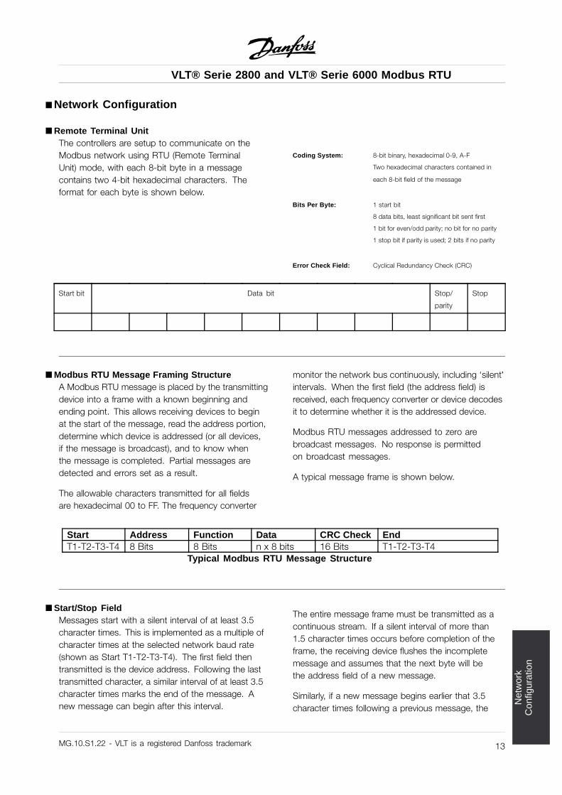
åRemote Terminal UnitThe controllers are setup to communicate on theModbus network using RTU (Remote TerminalUnit) mode, with each 8-bit byte in a messagecontains two 4-bit hexadecimal characters. Theformat for each byte is shown below.
Coding System: 8-bit binary, hexadecimal 0-9, A-F
Two hexadecimal characters contained in
each 8-bit field of the message
Bits Per Byte: 1 start bit
8 data bits, least significant bit sent first
1 bit for even/odd parity; no bit for no parity
1 stop bit if parity is used; 2 bits if no parity
Error Check Field: Cyclical Redundancy Check (CRC)
Start bit Data bit Stop/
parity
Stop
åModbus RTU Message Framing StructureA Modbus RTU message is placed by the transmittingdevice into a frame with a known beginning andending point. This allows receiving devices to beginat the start of the message, read the address portion,determine which device is addressed (or all devices,if the message is broadcast), and to know whenthe message is completed. Partial messages aredetected and errors set as a result.
The allowable characters transmitted for all fieldsare hexadecimal 00 to FF. The frequency converter
monitor the network bus continuously, including ‘silent’intervals. When the first field (the address field) isreceived, each frequency converter or device decodesit to determine whether it is the addressed device.
Modbus RTU messages addressed to zero arebroadcast messages. No response is permittedon broadcast messages.
A typical message frame is shown below.
Start Address Function Data CRC Check EndT1-T2-T3-T4 8 Bits 8 Bits n x 8 bits 16 Bits T1-T2-T3-T4
Typical Modbus RTU Message Structure
åStart/Stop FieldMessages start with a silent interval of at least 3.5character times. This is implemented as a multiple ofcharacter times at the selected network baud rate(shown as Start T1-T2-T3-T4). The first field thentransmitted is the device address. Following the lasttransmitted character, a similar interval of at least 3.5character times marks the end of the message. Anew message can begin after this interval.
The entire message frame must be transmitted as acontinuous stream. If a silent interval of more than1.5 character times occurs before completion of theframe, the receiving device flushes the incompletemessage and assumes that the next byte will bethe address field of a new message.
Similarly, if a new message begins earlier that 3.5character times following a previous message, the
MG.10.S1.22 - VLT is a registered Danfoss trademark 13
VLT® Serie 2800 and VLT® Serie 6000 Modbus RTU
receiving device will consider it a continuation of theprevious message. This will cause a timeout (no
response from the slave), since the value in the finalCRC field is not valid for the combined messages.
MG.10.S1.22 - VLT is a registered Danfoss trademark14
VLT® Serie 2800 and VLT® Serie 6000 Modbus RTU
Net
wor
kC
onfig
urat
ion
åAddress FieldThe address field of a message frame contains 8 bits.Valid slave device addresses are in the range of 0 –247 decimal. The individual slave devices are assignedaddresses in the range of 1 – 247. (0 is reserved forbroadcast mode, which all slaves recognize.) A masteraddresses a slave by placing the slave address in theaddress field of the message. When the slave sends itsresponse, it places its own address in this address fieldto let the master know which slave is responding.
å Function FieldThe function field of a message frame contains 8 bits.Valid codes are in the range of 1-FF. (See sectionModbus RTU Function Codes.) When a message issent from a master to a slave device, the function codefield tells the slave what kind of action to perform.
When the slave responds to the master, it usesthe function code field to indicate either a normal(error-free) response, or that some kind of erroroccurred (called an exception response). For a normalresponse, the slave simply echoes the original functioncode. For an exception response, the slave returnsa code that is equivalent to the original functioncode with its most-significant bit set to a logic 1. Inaddition, the slave places a unique code into thedata field of the response message. This tells themaster what kind of error occurred, or the reason forthe exception. See the chapter Exception Codes inthese operating instructions for definitions.
åData FieldThe data field is constructed using sets of twohexadecimal digits, in the range of 00 to FFhexadecimal. These are made from one RTU character.The data field of messages sent from a master to slavedevice contains additional information which the slavemust use to take the action defined by the functioncode. This can include items like coil or registeraddresses, the quantity of items to be handled, andthe count of actual data bytes in the field.
åCRC Check FieldMessages include an error-checking field that is basedon a cyclical redundancy check (CRC) method. The
CRC field checks the contents of the entire message. Itis applied regardless of any parity check method usedfor the individual characters of the message. The CRCvalue is calculated by the transmitting device, whichappends the CRC as the last field in the message. Thereceiving device recalculates a CRC during receipt ofthe message and compares the calculated value tothe actual value received in the CRC field. If the twovalues are not equal, a bus timeout results.
The error checking field contains a 16-bit binaryvalue implemented as two 8-bit bytes. When this isdone, the low-order byte of the field is appended first,followed by the high-order byte. The CRC high-orderbyte is the last byte sent in the message.
åCoil/Register AddressingAll data addresses in Modbus messages are referencedto zero. The first occurrence of a data item isaddressed as item number zero. For example:
The coil known as ‘coil 1’ in a programmable controlleris addressed as coil 0000 in the data addressfield of a Modbus message. Coil 127 decimal isaddressed as coil 007EHEX (126 decimal).
Holding register 40001 is addressed as register0000 in the data address field of the message.The function code field already specifies a ‘holdingregister’ operation. Therefore, the ‘4XXXX’ referenceis implicit. Holding register 40108 is addressedas register 006BHEX (107 decimal).
MG.10.S1.22 - VLT is a registered Danfoss trademark 15
VLT® Serie 2800 and VLT® Serie 6000 Modbus RTU
åParameter Handling
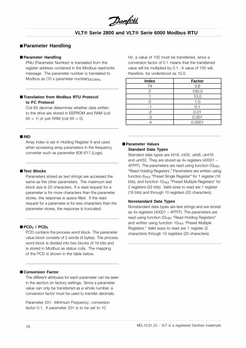
åParameter HandlingPNU (Parameter Number) is translated from theregister address contained in the Modbus read/writemessage. The parameter number is translated toModbus as (10 x parameter number)DECIMAL.
å Translation from Modbus RTU Protocolto FC ProtocolCoil 65 decimal determines whether data writtento the drive are stored in EEPROM and RAM (coil65 = 1) or just RAM (coil 65 = 0).
å INDArray index is set in Holding Register 9 and usedwhen accessing array parameters in the frequencyconverter such as parameter 606-617 (Logs).
å Text BlocksParameters stored as text strings are accessed thesame as the other parameters. The maximum textblock size is 20 characters. If a read request for aparameter is for more characters than the parameterstores, the response is space filled. If the readrequest for a parameter is for less characters than theparameter stores, the response is truncated.
åPCD1 / PCD2
PCD contains the process word block. The parametervalue block consists of 2 words (4 bytes). The processword block is divided into two blocks of 16 bits andis stored in Modbus as status coils. The mappingof the PCD is shown in the table below.
åConversion FactorThe different attributes for each parameter can be seenin the section on factory settings. Since a parametervalue can only be transferred as a whole number, aconversion factor must be used to transfer decimals.
Parameter 201: Minimum Frequency, conversionfactor 0.1. If parameter 201 is to be set to 10
Hz, a value of 100 must be transferred, since aconversion factor of 0.1 means that the transferredvalue will be multiplied by 0.1. A value of 100 will,therefore, be understood as 10.0.
Index Factor74 3.62 100.01 10.00 1.0-1 0.1-2 0.01-3 0.001-4 0.0001
åParameter ValuesStandard Data TypesStandard data types are int16, int32, uint8, uint16and uint32. They are stored as 4x registers (40001 –4FFFF). The parameters are read using function 03HEX
"Read Holding Registers." Parameters are written usingfunction 6HEX "Preset Single Register" for 1 register (16bits), and function 10HEX "Preset Multiple Registers" for2 registers (32 bits). Valid sizes to read are 1 register(16 bits) and through 10 registers (20 characters).
Nonstandard Data TypesNonstandard data types are text strings and are storedas 4x registers (40001 – 4FFFF). The parameters areread using function 03HEX "Read Holding Registers"and written using function 10HEX "Preset MultipleRegisters." Valid sizes to read are 1 register (2characters) through 10 registers (20 characters).
MG.10.S1.22 - VLT is a registered Danfoss trademark16
VLT® Serie 2800 and VLT® Serie 6000 Modbus RTU
Par
amet
erH
andl
ing
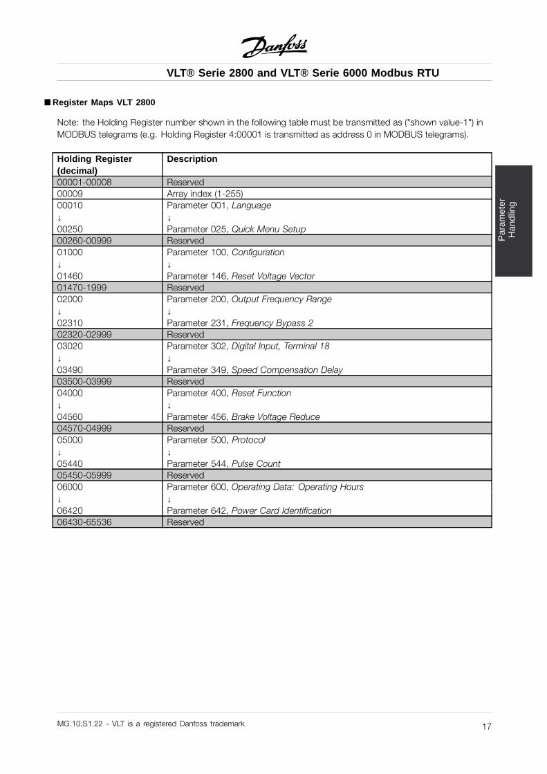
åRegister Maps VLT 2800
Note: the Holding Register number shown in the following table must be transmitted as ("shown value-1") inMODBUS telegrams (e.g. Holding Register 4:00001 is transmitted as address 0 in MODBUS telegrams).
Holding Register(decimal)
Description
00001-00008 Reserved00009 Array index (1-255)00010 Parameter 001, Language↓ ↓00250 Parameter 025, Quick Menu Setup00260-00999 Reserved01000 Parameter 100, Configuration↓ ↓01460 Parameter 146, Reset Voltage Vector01470-1999 Reserved02000 Parameter 200, Output Frequency Range↓ ↓02310 Parameter 231, Frequency Bypass 202320-02999 Reserved03020 Parameter 302, Digital Input, Terminal 18↓ ↓03490 Parameter 349, Speed Compensation Delay03500-03999 Reserved04000 Parameter 400, Reset Function↓ ↓04560 Parameter 456, Brake Voltage Reduce04570-04999 Reserved05000 Parameter 500, Protocol↓ ↓05440 Parameter 544, Pulse Count05450-05999 Reserved06000 Parameter 600, Operating Data: Operating Hours↓ ↓06420 Parameter 642, Power Card Identification06430-65536 Reserved
MG.10.S1.22 - VLT is a registered Danfoss trademark 17
VLT® Serie 2800 and VLT® Serie 6000 Modbus RTU
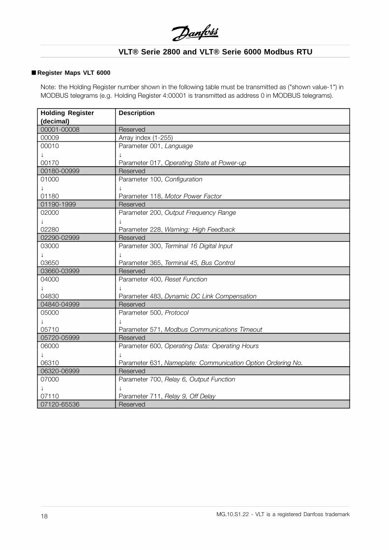
åRegister Maps VLT 6000
Note: the Holding Register number shown in the following table must be transmitted as ("shown value-1") inMODBUS telegrams (e.g. Holding Register 4:00001 is transmitted as address 0 in MODBUS telegrams).
Holding Register(decimal)
Description
00001-00008 Reserved00009 Array index (1-255)00010 Parameter 001, Language↓ ↓00170 Parameter 017, Operating State at Power-up00180-00999 Reserved01000 Parameter 100, Configuration↓ ↓01180 Parameter 118, Motor Power Factor01190-1999 Reserved02000 Parameter 200, Output Frequency Range↓ ↓02280 Parameter 228, Warning: High Feedback02290-02999 Reserved03000 Parameter 300, Terminal 16 Digital Input↓ ↓03650 Parameter 365, Terminal 45, Bus Control03660-03999 Reserved04000 Parameter 400, Reset Function↓ ↓04830 Parameter 483, Dynamic DC Link Compensation04840-04999 Reserved05000 Parameter 500, Protocol↓ ↓05710 Parameter 571, Modbus Communications Timeout05720-05999 Reserved06000 Parameter 600, Operating Data: Operating Hours↓ ↓06310 Parameter 631, Nameplate: Communication Option Ordering No.06320-06999 Reserved07000 Parameter 700, Relay 6, Output Function↓ ↓07110 Parameter 711, Relay 9, Off Delay07120-65536 Reserved
MG.10.S1.22 - VLT is a registered Danfoss trademark18
VLT® Serie 2800 and VLT® Serie 6000 Modbus RTU
Par
amet
erH
andl
ing
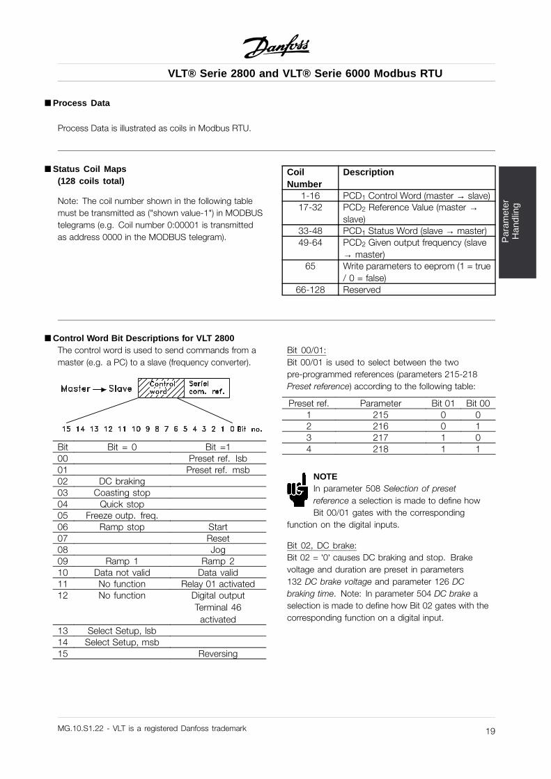
åProcess Data
Process Data is illustrated as coils in Modbus RTU.
åStatus Coil Maps(128 coils total)
Note: The coil number shown in the following tablemust be transmitted as ("shown value-1") in MODBUStelegrams (e.g. Coil number 0:00001 is transmittedas address 0000 in the MODBUS telegram).
CoilNumber
Description
1-16 PCD1 Control Word (master → slave)17-32 PCD2 Reference Value (master →
slave)33-48 PCD1 Status Word (slave → master)49-64 PCD2 Given output frequency (slave
→ master)65 Write parameters to eeprom (1 = true
/ 0 = false)66-128 Reserved
åControl Word Bit Descriptions for VLT 2800The control word is used to send commands from amaster (e.g. a PC) to a slave (frequency converter).
Bit Bit = 0 Bit =100 Preset ref. lsb01 Preset ref. msb02 DC braking03 Coasting stop04 Quick stop05 Freeze outp. freq.06 Ramp stop Start07 Reset08 Jog09 Ramp 1 Ramp 210 Data not valid Data valid11 No function Relay 01 activated12 No function Digital output
Terminal 46activated
13 Select Setup, lsb14 Select Setup, msb15 Reversing
Bit 00/01:Bit 00/01 is used to select between the twopre-programmed references (parameters 215-218Preset reference) according to the following table:
Preset ref. Parameter Bit 01 Bit 001 215 0 02 216 0 13 217 1 04 218 1 1
NOTEIn parameter 508 Selection of presetreference a selection is made to define howBit 00/01 gates with the corresponding
function on the digital inputs.
Bit 02, DC brake:Bit 02 = ’0’ causes DC braking and stop. Brakevoltage and duration are preset in parameters132 DC brake voltage and parameter 126 DCbraking time. Note: In parameter 504 DC brake aselection is made to define how Bit 02 gates with thecorresponding function on a digital input.
MG.10.S1.22 - VLT is a registered Danfoss trademark 19
VLT® Serie 2800 and VLT® Serie 6000 Modbus RTU
Bit 03, Coasting stop:Bit 03 = ’0’ causes the frequency converter toimmediately "let go" of the motor (the output transistorsare "shut off"), so that it coasts to a standstill.Bit 03 = ’1’ causes the frequency converter to be ablestart the motor if the other starting conditions havebeen fulfilled. Note: In parameter 502 Coasting stopa selection is made to define how Bit 03 gates withthe corresponding function on a digital input.
Bit 04, Quick stop:Bit 04 = ’0’ causes a stop, in which the motor’sspeed is ramped down to stop via parameter212 Quick stop ramp-down time.
Bit 05, Freeze output frequency:Bit 05 = ’0’ causes the present output frequency(in Hz) to freeze. The frozen output frequency cannow only be changed by means of the digital inputsprogrammed to Speed up and Speed down.
NOTEIf Freeze output is active, the frequencyconverter cannot be stopped via Bit 06 Startor via a digital input. The frequency converter
can only be stopped by the following:• Bit 03 Coasting stop• Bit 02 DC braking• Digital input programmed to DC braking, Coasting
stop or Reset and coasting stop.
Bit 06, Ramp stop/start:Bit 06 = ’0’ causes a stop, in which the motor’sspeed is ramped down to stop via the selectedramp down parameter.Bit 06 = ’1’ causes the frequency converter to be ableto start the motor, if the other starting conditions havebeen fulfilled. Note: In parameter 505 Start a selectionis made to define how Bit 06 Ramp stop/start gateswith the corresponding function on a digital input.
Bit 07, Reset:Bit 07 = ’0’ does not cause a reset.Bit 07 = ’1’ causes the reset of a trip. Reset isactivated on the signal’s leading edge, i.e. whenchanging from logic ’0’ to logic ’1’.
Bit 08, Jog:Bit 08 = ’1’ causes the output frequency to bedetermined by parameter 213 Jog frequency.
Bit 09, Selection of ramp 1/2:Bit 09 = "0" means that ramp 1 is active (parameters207/208). Bit 09 = "1" means that ramp 2(parameters 209/210) is active.
Bit 10, Data not valid/Data valid:Is used to tell the frequency converter whether thecontrol word is to be used or ignored. Bit 10 = ’0’causes the control word to be ignored, Bit 10 = ’1’causes the control word to be used. This functionis relevant, because the control word is alwayscontained in the telegram, regardless of which typeof telegram is used, i.e. it is possible to turn off thecontrol word if you do not wish to use it in connectionwith updating or reading parameters.
Bit 11, Relay 01:Bit 11 = "0" Relay not activated.Bit 11 = "1" Relay 01 activated, provided Controlword bit has been chosen in parameter 323.
Bit 12, Digital output, terminal 46:Bit 12 = "0" Digital output has not been activated.Bit 12 = "1" Digital output has been activated, providedControl word bit has been chosen in parameter 341.
Bit 13/14, Selection of Setup:Bits 13 and 14 are used to choose from the four menuSetups according to the following table:
Setup Bit 14 Bit 131 0 02 0 13 1 04 1 1
The function is only possible when Multi-Setups isselected in parameter 004 Active Setup .Note: I parameter 507 Selection of Setup a selectionis made to define how Bit 13/14 gates with thecorresponding function on the digital inputs.
Bit 15 Reversing:Bit 15 = ’0’ causes no reversing.Bit 15 = ’1’ causes reversing.Note: In the factory setting reversing is set todigital in parameter 506 Reversing. Bit 15 only
MG.10.S1.22 - VLT is a registered Danfoss trademark20
VLT® Serie 2800 and VLT® Serie 6000 Modbus RTU
Par
amet
erH
andl
ing
causes reversing when either Ser. communication, Logic or or Logic and is selected.
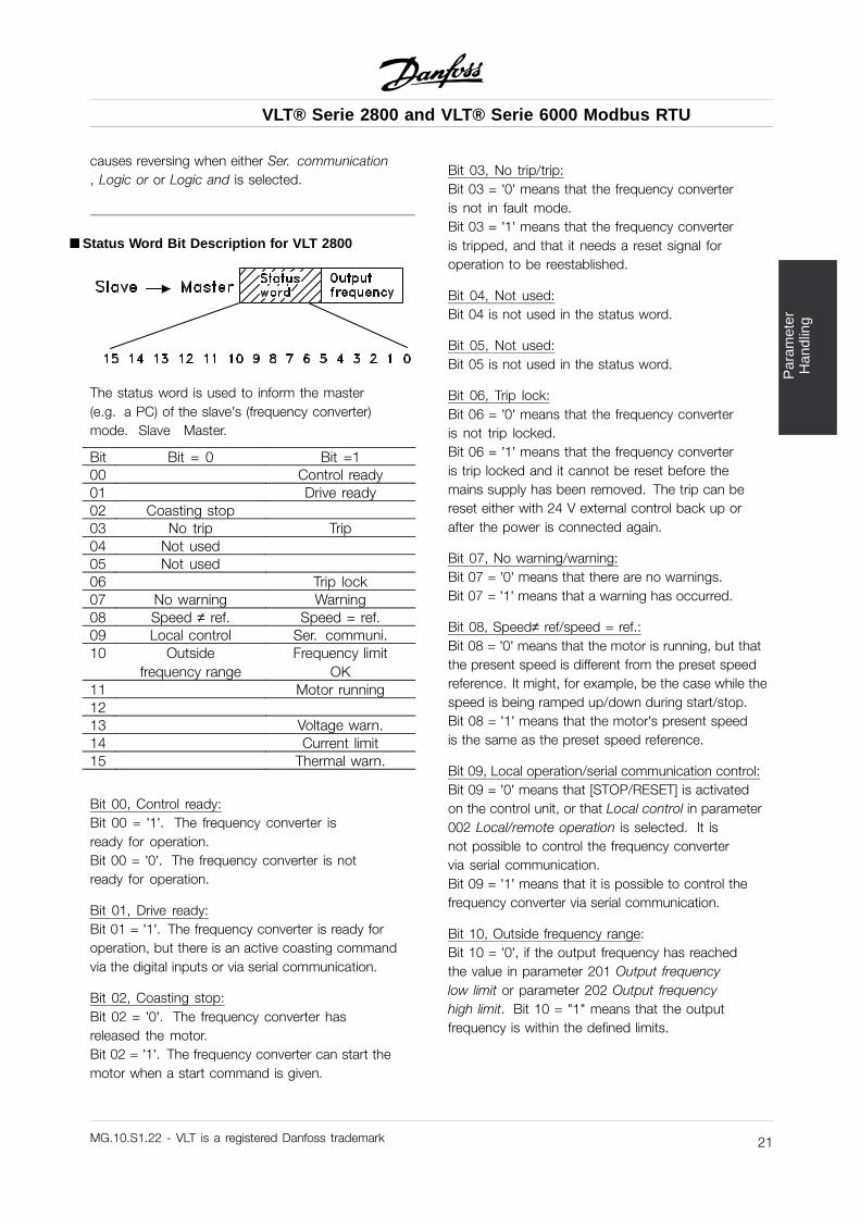
åStatus Word Bit Description for VLT 2800
The status word is used to inform the master(e.g. a PC) of the slave’s (frequency converter)mode. Slave Master.
Bit Bit = 0 Bit =100 Control ready01 Drive ready02 Coasting stop03 No trip Trip04 Not used05 Not used06 Trip lock07 No warning Warning08 Speed ≠ ref. Speed = ref.09 Local control Ser. communi.10 Outside
frequency rangeFrequency limit
OK11 Motor running1213 Voltage warn.14 Current limit15 Thermal warn.
Bit 00, Control ready:Bit 00 = ’1’. The frequency converter isready for operation.Bit 00 = ’0’. The frequency converter is notready for operation.
Bit 01, Drive ready:Bit 01 = ’1’. The frequency converter is ready foroperation, but there is an active coasting commandvia the digital inputs or via serial communication.
Bit 02, Coasting stop:Bit 02 = ’0’. The frequency converter hasreleased the motor.Bit 02 = ’1’. The frequency converter can start themotor when a start command is given.
Bit 03, No trip/trip:Bit 03 = ’0’ means that the frequency converteris not in fault mode.Bit 03 = ’1’ means that the frequency converteris tripped, and that it needs a reset signal foroperation to be reestablished.
Bit 04, Not used:Bit 04 is not used in the status word.
Bit 05, Not used:Bit 05 is not used in the status word.
Bit 06, Trip lock:Bit 06 = ’0’ means that the frequency converteris not trip locked.Bit 06 = ’1’ means that the frequency converteris trip locked and it cannot be reset before themains supply has been removed. The trip can bereset either with 24 V external control back up orafter the power is connected again.
Bit 07, No warning/warning:Bit 07 = ’0’ means that there are no warnings.Bit 07 = ’1’ means that a warning has occurred.
Bit 08, Speed≠ ref/speed = ref.:Bit 08 = ’0’ means that the motor is running, but thatthe present speed is different from the preset speedreference. It might, for example, be the case while thespeed is being ramped up/down during start/stop.Bit 08 = ’1’ means that the motor’s present speedis the same as the preset speed reference.
Bit 09, Local operation/serial communication control:Bit 09 = ’0’ means that [STOP/RESET] is activatedon the control unit, or that Local control in parameter002 Local/remote operation is selected. It isnot possible to control the frequency convertervia serial communication.Bit 09 = ’1’ means that it is possible to control thefrequency converter via serial communication.
Bit 10, Outside frequency range:Bit 10 = ’0’, if the output frequency has reachedthe value in parameter 201 Output frequencylow limit or parameter 202 Output frequencyhigh limit. Bit 10 = "1" means that the outputfrequency is within the defined limits.
MG.10.S1.22 - VLT is a registered Danfoss trademark 21
VLT® Serie 2800 and VLT® Serie 6000 Modbus RTU
Bit 11, Running/not running:Bit 11 = ’0’ means that the motor is not running.Bit 11 = ’1’ means that the frequency converterhas a start signal or that the output frequencyis greater than 0 Hz.
Bit 13, Voltage warning high/low:Bit 13 = ’0’ means that there are no voltage warnings.Bit 13 = ’1’ means that the DC voltage in the frequencyconverter’s intermediate circuit is too low or too high.
Bit 14, Current limit:Bit 14 = ’0’ means that the output current is less thanthe value in parameter 221 Current Limit ILIM.Bit 14 = ’1’ means that the output current is greater thanthe value in parameter 221 Current LimitILIM and that thefrequency converter will trip after a set period of time.
Bit 15, Thermal warning:Bit 15 = ’0’ means that there is no thermal warning.Bit 15 = ’1’ means that the temperature limit has beenexceeded in either the motor, frequency converter orfrom a thermistor that is connected to a digital input.
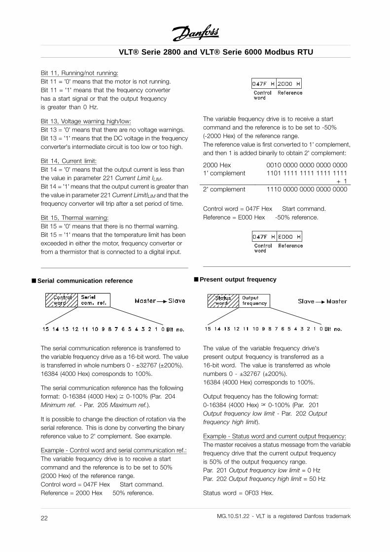
åSerial communication reference
The serial communication reference is transferred tothe variable frequency drive as a 16-bit word. The valueis transferred in whole numbers 0 - ±32767 (±200%).16384 (4000 Hex) corresponds to 100%.
The serial communication reference has the followingformat: 0-16384 (4000 Hex) 0-100% (Par. 204Minimum ref. - Par. 205 Maximum ref.).
It is possible to change the direction of rotation via theserial reference. This is done by converting the binaryreference value to 2’ complement. See example.
Example - Control word and serial communication ref.:The variable frequency drive is to receive a startcommand and the reference is to be set to 50%(2000 Hex) of the reference range.Control word = 047F Hex Start command.Reference = 2000 Hex 50% reference.
The variable frequency drive is to receive a startcommand and the reference is to be set to -50%(-2000 Hex) of the reference range.The reference value is first converted to 1’ complement,and then 1 is added binarily to obtain 2’ complement:
2000 Hex 0010 0000 0000 0000 00001’ complement 1101 1111 1111 1111 1111
+ 12’ complement 1110 0000 0000 0000 0000
Control word = 047F Hex Start command.Reference = E000 Hex -50% reference.
åPresent output frequency
The value of the variable frequency drive’spresent output frequency is transferred as a16-bit word. The value is transferred as wholenumbers 0 - ±32767 (±200%).16384 (4000 Hex) corresponds to 100%.
Output frequency has the following format:0-16384 (4000 Hex) 0-100% (Par. 201Output frequency low limit - Par. 202 Outputfrequency high limit).
Example - Status word and current output frequency:The master receives a status message from the variablefrequency drive that the current output frequencyis 50% of the output frequency range.Par. 201 Output frequency low limit = 0 HzPar. 202 Output frequency high limit = 50 Hz
Status word = 0F03 Hex.
MG.10.S1.22 - VLT is a registered Danfoss trademark22
VLT® Serie 2800 and VLT® Serie 6000 Modbus RTU
Par
amet
erH
andl
ing
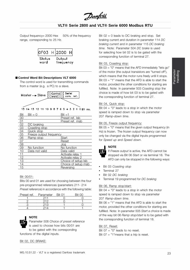
Output frequency= 2000 Hex 50% of the frequencyrange, corresponding to 25 Hz.
åControl Word Bit Descriptions VLT 6000The control word is used for transmitting commandsfrom a master (e.g. a PC) to a slave.
Bit Bit = 0 Bit =100 Preset ref. lsb01 Preset ref. msb02 DC braking03 Coasting stop04 Quick stop05 Freeze output frequency06 Ramp stop Start07 Reset08 Jog09 No function No function10 Data not valid Data valid11 Activate relay 112 Activate relay 213 Choice of setup lsb14 Choice of setup msb15 Reversing
Bit 00/01:Bits 00 and 01 are used for choosing between the fourpre-programmed references (parameters 211- 214Preset reference) in accordance with the following table:
Preset ref. Parameter Bit 01 Bit 001 211 0 02 212 0 13 213 1 04 214 1 1
NOTEParameter 508 Choice of preset referenceis used to choose how bits 00/01 areto be gated with the corresponding
functions of the digital inputs.
Bit 02, DC BRAKE:
Bit 02 = 0 leads to DC braking and stop. Setbraking current and duration in parameter 114 DCbraking current and in parameter 115 DC brakingtime. Note: Parameter 504 DC brake is usedfor selecting how bit 02 is to be gated with thecorresponding function of terminal 27.
Bit 03, Coasting stop:Bit 03 = "0" means that the AFD immediately "lets go"of the motor (the output transistors are "turned off"),which means that the motor runs freely until it stops.Bit 03 = "1" means that the AFD is able to start themotor, provided the other conditions for starting arefulfilled. Note: In parameter 503 Coasting stop thechoice is made of how bit 03 is to be gated withthe corresponding function of terminal 27.
Bit 04, Quick stop:Bit 04 = "0" leads to a stop in which the motorspeed is ramped down to stop via parameter207 Ramp-down time.
Bit 05, Freeze output frequency:Bit 05 = "0" means that the given output frequency (inHz) is frozen. The frozen output frequency can nowonly be changed via the digital inputs programmedfor Speed up and Speed down.
NOTEIf Freeze output is active, the AFD cannot bestopped via Bit 06 Start or via terminal 18. TheAFD can only be stopped in the following ways:
• Bit 03 Coasting stop• Terminal 27• Bit 02 DC braking• Terminal 19 programmed for DC braking
Bit 06, Ramp stop/start:Bit 04 = "0" leads to a stop in which the motorspeed is ramped down to stop via parameter207 Ramp-down time.Bit 06 = "1" means that the AFD is able to start themotor, provided the other conditions for starting arefulfilled. Note: In parameter 505 Start a choice is madeof the way bit 06 Ramp stop/start is to be gated withthe corresponding function of terminal 18.
Bit 07, Reset:Bit 07 = "0" leads to no reset.Bit 07 = "1"means that a trip is reset.
MG.10.S1.22 - VLT is a registered Danfoss trademark 23
VLT® Serie 2800 and VLT® Serie 6000 Modbus RTU
Reset is activated on the leading edge of the signal,i.e. at the change from logic ’0’ to logic ’1’.
Bit 08, Jog:Bit 08 = "1" means that the output frequency isdetermined by parameter 209 Jog frequency.
Bit 09, No function:Bit 09 has no function.
Bit 10, Data not valid/Data valid:Used for telling the AFD whether the control is to beused or ignored. Bit 10 = "0" means that the controlword is ignored. Bit 10 = "1" means that the controlword is used. This function is relevant because thecontrol word is always contained in the telegram,regardless of the type of telegram used, i.e. it is possibleto disconnect the control word if it is not to be used inconnection with updating or reading of parameters.
Bit 11, Relay 1:Bit 11 = "0": Relay 1 is not activated.Bit 11 = "1": Relay 1 is activated, providedControl word bits 11/12 has been selected inparameter 323 Relay outputs.
Bit 12, Relay 2:Bit 12 = "0": Relay 2 is not activated.Bit 12 = "1": Relay 2 is activated, providedControl word bits 11/12has been selected inparameter 326 Relay outputs.
NOTEIf the time-out period set in parameter 556Bus time interval function is exceeded, relays1 and 2 will lose their voltage if they have
been activated via serial communication.
Bits 13/14, Choice of Setup:Bits 13 and 14 are used to choose among the fourmenu Setups in accordance with the following table:
Setup Bit 14 Bit 131 0 02 0 13 1 04 1 1
This function is only possible if Multi-setups hasbeen selected in parameter 004.Note: In parameter 507 Choice of Setup a choice ismade of the way bits 13/14 are to be gated with thecorresponding function of the digital inputs.
Bit 15, No function/reversing:Bit 15 = "0" leads to no reversing.Bit 15 = "1" leads to reversing.
Please note that, in the factory setting, reversing hasbeen selected as digital in parameter 506 Reversing,which means that bit 15 only leads to reversing, ifbus, logic or orlogic and has been selected (however,logic and only together with terminal 19).
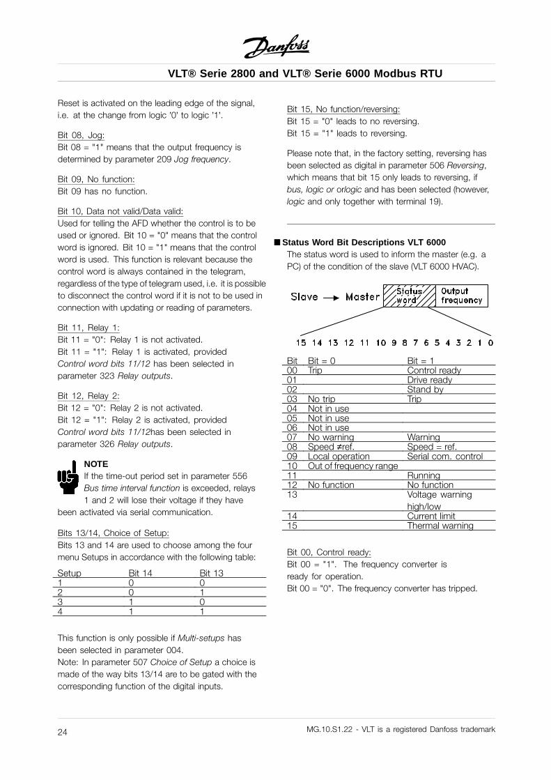
åStatus Word Bit Descriptions VLT 6000The status word is used to inform the master (e.g. aPC) of the condition of the slave (VLT 6000 HVAC).
Bit Bit = 0 Bit = 100 Trip Control ready01 Drive ready02 Stand by03 No trip Trip04 Not in use05 Not in use06 Not in use07 No warning Warning08 Speed ≠ref. Speed = ref.09 Local operation Serial com. control10 Out of frequency range11 Running12 No function No function13 Voltage warning
high/low14 Current limit15 Thermal warning
Bit 00, Control ready:Bit 00 = "1". The frequency converter isready for operation.Bit 00 = "0". The frequency converter has tripped.
MG.10.S1.22 - VLT is a registered Danfoss trademark24
VLT® Serie 2800 and VLT® Serie 6000 Modbus RTU
Par
amet
erH
andl
ing
Bit 01, Drive ready:Bit 01 = "1". The frequency converter is ready foroperation, but terminal 27 is a logic ’0’ and/or a coastingcommand has been received via serial communication.
Bit 02, Stand by:Bit 02 = "1". The frequency converter is able to startthe motor when a start command is given.
Bit 03, No trip/trip:Bit 03 = "0" means that the VLT 6000 HVAC is notin an error state. Bit 03 = "1" means that the VLT6000 HVAC has tripped and needs a reset signalin order for operation to be resumed.Bit 04, Not in use:Bit 04 is not used in the status word.
Bit 05, Not in use:Bit 05 is not used in the status word.
Bit 06, Trip lock:Bit 06: "1" means that there is a trip lock.
Bit 07, No warning/warning:Bit 07 = "0" means there is no warning.Bit 07 = "1" means a warning has occurred.
NOTEAll warnings are discribed in the OperationInstructions.
Bit 08, Speed ≠ref./speed = ref.:Bit 08 = "0" means that the motor is running, butthat the present speed is different from the presetspeed reference. This may be the case, i.a. whenthe speed is ramped up/down at start/stop.Bit 08 = "1" means that the present motor speedequals the preset speed reference.
Bit 09, Local operation/serial communication control:Bit 09 = "0" means that OFF/STOP has been activatedon the control unit, or that the VLT 6000 HVAC isin Hand mode. It is not possible to control the VLTfrequency converter via serial communication.Bit 09 = "1" means that it is possible to control thefrequency converter via serial communication.
Bit 10, Out of frequency range:Bit 10 = "0" if the output frequency has reachedthe value in parameter 201 Output frequencylow limit or parameter 202 Output frequency
high limit. Bit 10 = "1" means that the outputfrequency is within the limits stated.
Bit 11, Not running/running:Bit 11 = "0" means that the motor is not running.Bit 11 = "1" means that the VLT 6000 HVAC has a startsignal, or that the output frequency is greater than 0 Hz.
Bit 12, No function:Bit 12 has no function.
Bit 13, Voltage warning high/low:Bit 13 = "0" means that there is no voltage warning.Bit 13 = "1" means that the DC voltage of the VLT 6000HVAC intermediate circuit is too low or too high.See the voltage limits on page 160.
Bit 14, Current limit:Bit 14 = "0" means that the output current is smallerthan the value in parameter 215 Current limit ILIM.Bit 14 = "1" means that the output current is higherthan the value in parameter 215 Current limit ILIM andthe frequency converter will trip after the time set inparameter 412 Trip delay overcurrent, ILIM has passed.
Bit 15, Thermal warning:
Bit 15 = "0" means there is no thermal warning.Bit 15 = "1" means that the temperature limit has beenexceeded either in the motor, in the frequency converteror from a thermistor connected to an analogue input.
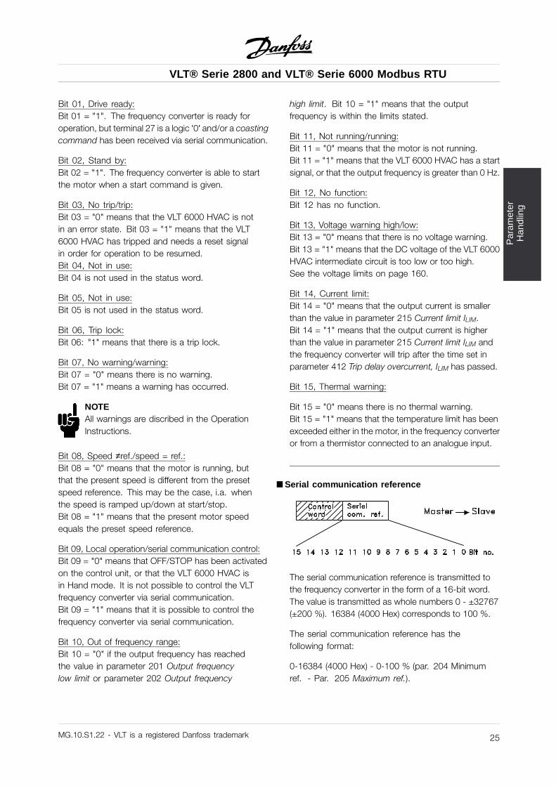
åSerial communication reference
The serial communication reference is transmitted tothe frequency converter in the form of a 16-bit word.The value is transmitted as whole numbers 0 - ±32767(±200 %). 16384 (4000 Hex) corresponds to 100 %.
The serial communication reference has thefollowing format:
0-16384 (4000 Hex) - 0-100 % (par. 204 Minimumref. - Par. 205 Maximum ref.).
MG.10.S1.22 - VLT is a registered Danfoss trademark 25
VLT® Serie 2800 and VLT® Serie 6000 Modbus RTU
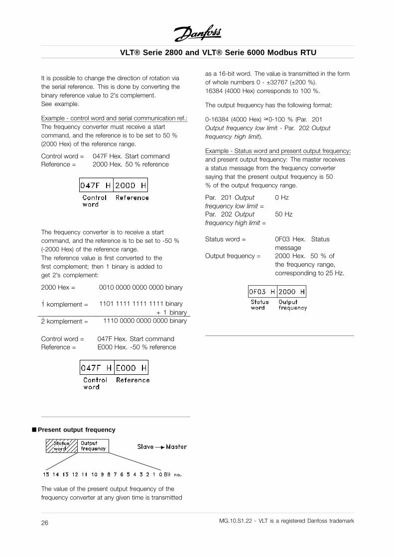
It is possible to change the direction of rotation viathe serial reference. This is done by converting thebinary reference value to 2’s complement.See example.
Example - control word and serial communication ref.:The frequency converter must receive a startcommand, and the reference is to be set to 50 %(2000 Hex) of the reference range.
Control word = 047F Hex. Start commandReference = 2000 Hex. 50 % reference
The frequency converter is to receive a startcommand, and the reference is to be set to -50 %(-2000 Hex) of the reference range.The reference value is first converted to thefirst complement; then 1 binary is added toget 2’s complement:
2000 Hex = 0010 0000 0000 0000 binary
1́ komplement = 1101 1111 1111 1111 binary+ 1 binary
2́ komplement = 1110 0000 0000 0000 binary
Control word = 047F Hex. Start commandReference = E000 Hex. -50 % reference
åPresent output frequency
The value of the present output frequency of thefrequency converter at any given time is transmitted
as a 16-bit word. The value is transmitted in the formof whole numbers 0 - ±32767 (±200 %).16384 (4000 Hex) corresponds to 100 %.
The output frequency has the following format:
0-16384 (4000 Hex) 0-100 % (Par. 201Output frequency low limit - Par. 202 Outputfrequency high limit).
Example - Status word and present output frequency:and present output frequency: The master receivesa status message from the frequency convertersaying that the present output frequency is 50% of the output frequency range.
Par. 201 Outputfrequency low limit =
0 Hz
Par. 202 Outputfrequency high limit =
50 Hz
Status word = 0F03 Hex. Statusmessage
Output frequency = 2000 Hex. 50 % ofthe frequency range,corresponding to 25 Hz.
MG.10.S1.22 - VLT is a registered Danfoss trademark26
VLT® Serie 2800 and VLT® Serie 6000 Modbus RTU
Sup
port
ed M
odbu
s R
TU
Fun
ctio
n C
odes
åSupported Modbus RTU Function CodesThis section describes the following functionssupported by the Modbus RTU.
Read Coil Status (01HEX) Read Holding Registers (03HEX)Force Single Coil (05HEX) Preset Single Register (06HEX)Force Multiple Coils (0FHEX) Preset Multiple Registers (10HEX)
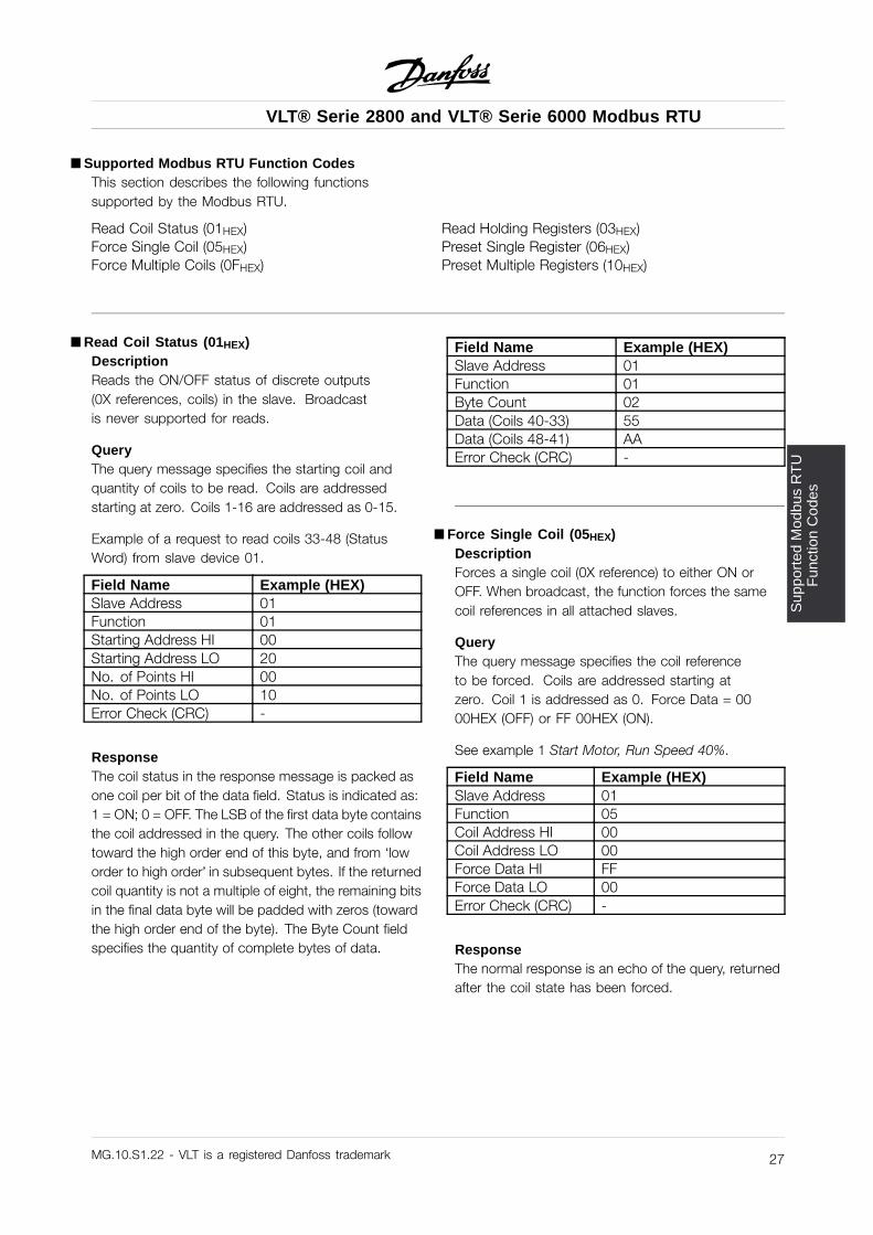
åRead Coil Status (01HEX)DescriptionReads the ON/OFF status of discrete outputs(0X references, coils) in the slave. Broadcastis never supported for reads.
QueryThe query message specifies the starting coil andquantity of coils to be read. Coils are addressedstarting at zero. Coils 1-16 are addressed as 0-15.
Example of a request to read coils 33-48 (StatusWord) from slave device 01.
Field Name Example (HEX)Slave Address 01Function 01Starting Address HI 00Starting Address LO 20No. of Points HI 00No. of Points LO 10Error Check (CRC) -
ResponseThe coil status in the response message is packed asone coil per bit of the data field. Status is indicated as:1 = ON; 0 = OFF. The LSB of the first data byte containsthe coil addressed in the query. The other coils followtoward the high order end of this byte, and from ‘loworder to high order’ in subsequent bytes. If the returnedcoil quantity is not a multiple of eight, the remaining bitsin the final data byte will be padded with zeros (towardthe high order end of the byte). The Byte Count fieldspecifies the quantity of complete bytes of data.
Field Name Example (HEX)Slave Address 01Function 01Byte Count 02Data (Coils 40-33) 55Data (Coils 48-41) AAError Check (CRC) -
å Force Single Coil (05HEX)DescriptionForces a single coil (0X reference) to either ON orOFF. When broadcast, the function forces the samecoil references in all attached slaves.
QueryThe query message specifies the coil referenceto be forced. Coils are addressed starting atzero. Coil 1 is addressed as 0. Force Data = 0000HEX (OFF) or FF 00HEX (ON).
See example 1 Start Motor, Run Speed 40%.
Field Name Example (HEX)Slave Address 01Function 05Coil Address HI 00Coil Address LO 00Force Data HI FFForce Data LO 00Error Check (CRC) -
ResponseThe normal response is an echo of the query, returnedafter the coil state has been forced.
MG.10.S1.22 - VLT is a registered Danfoss trademark 27
VLT® Serie 2800 and VLT® Serie 6000 Modbus RTU
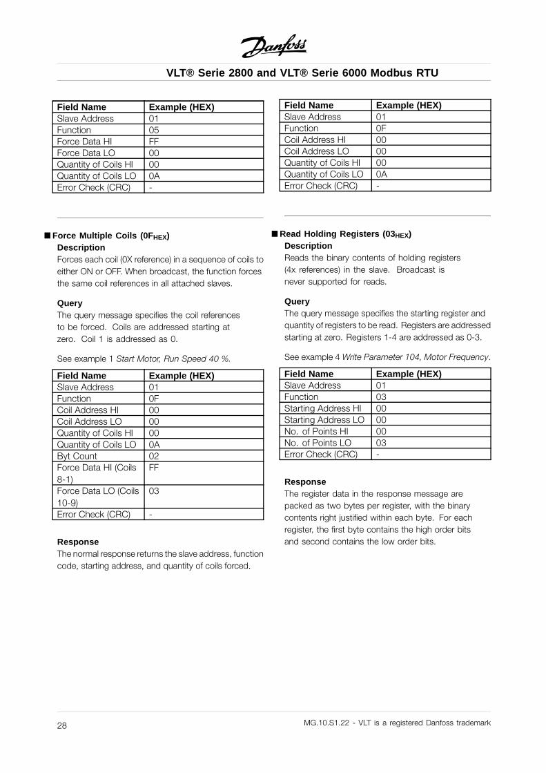
Field Name Example (HEX)Slave Address 01Function 05Force Data HI FFForce Data LO 00Quantity of Coils HI 00Quantity of Coils LO 0AError Check (CRC) -
å Force Multiple Coils (0FHEX)DescriptionForces each coil (0X reference) in a sequence of coils toeither ON or OFF. When broadcast, the function forcesthe same coil references in all attached slaves.
QueryThe query message specifies the coil referencesto be forced. Coils are addressed starting atzero. Coil 1 is addressed as 0.
See example 1 Start Motor, Run Speed 40 %.
Field Name Example (HEX)Slave Address 01Function 0FCoil Address HI 00Coil Address LO 00Quantity of Coils HI 00Quantity of Coils LO 0AByt Count 02Force Data HI (Coils8-1)
FF
Force Data LO (Coils10-9)
03
Error Check (CRC) -
ResponseThe normal response returns the slave address, functioncode, starting address, and quantity of coils forced.
Field Name Example (HEX)Slave Address 01Function 0FCoil Address HI 00Coil Address LO 00Quantity of Coils HI 00Quantity of Coils LO 0AError Check (CRC) -
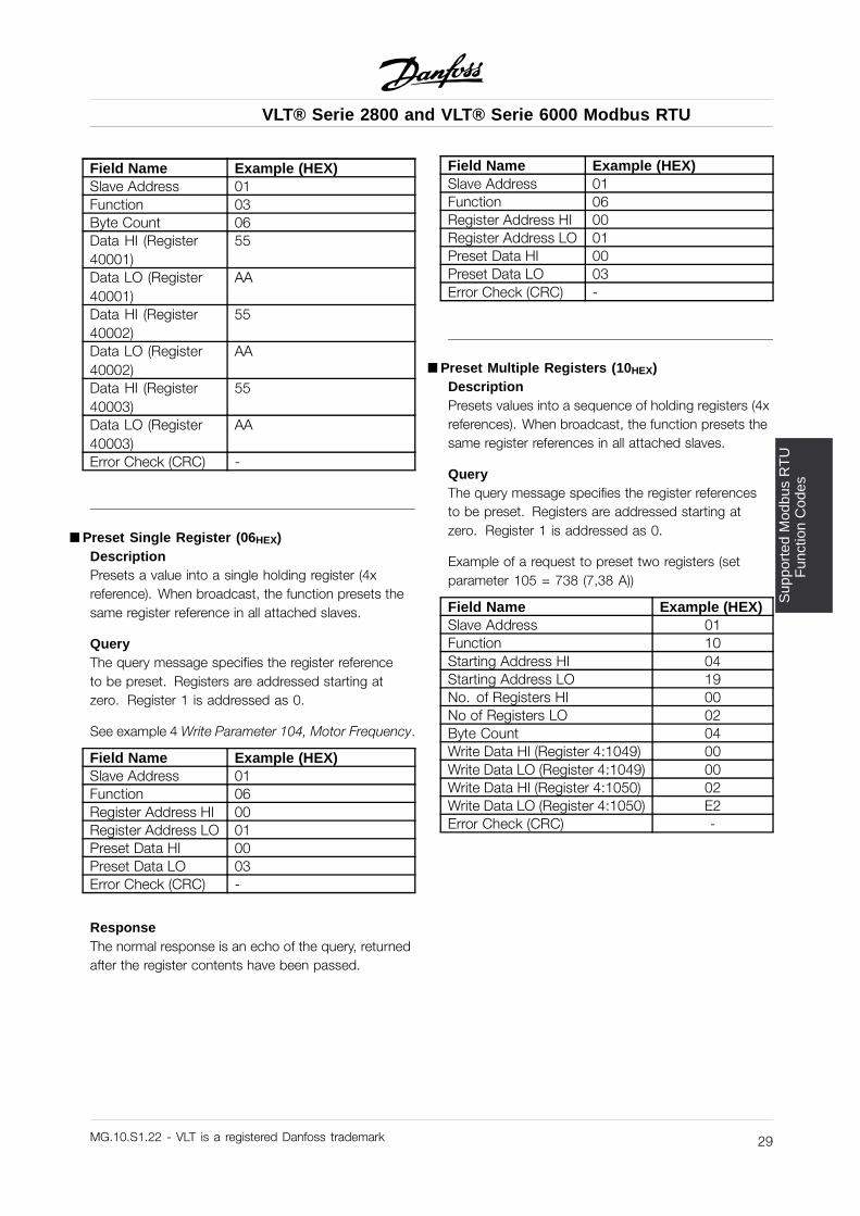
åRead Holding Registers (03HEX)DescriptionReads the binary contents of holding registers(4x references) in the slave. Broadcast isnever supported for reads.
QueryThe query message specifies the starting register andquantity of registers to be read. Registers are addressedstarting at zero. Registers 1-4 are addressed as 0-3.
See example 4 Write Parameter 104, Motor Frequency.
Field Name Example (HEX)Slave Address 01Function 03Starting Address HI 00Starting Address LO 00No. of Points HI 00No. of Points LO 03Error Check (CRC) -
ResponseThe register data in the response message arepacked as two bytes per register, with the binarycontents right justified within each byte. For eachregister, the first byte contains the high order bitsand second contains the low order bits.
MG.10.S1.22 - VLT is a registered Danfoss trademark28
VLT® Serie 2800 and VLT® Serie 6000 Modbus RTU
Sup
port
ed M
odbu
s R
TU
Fun
ctio
n C
odes
Field Name Example (HEX)Slave Address 01Function 03Byte Count 06Data HI (Register40001)
55
Data LO (Register40001)
AA
Data HI (Register40002)
55
Data LO (Register40002)
AA
Data HI (Register40003)
55
Data LO (Register40003)
AA
Error Check (CRC) -
åPreset Single Register (06HEX)DescriptionPresets a value into a single holding register (4xreference). When broadcast, the function presets thesame register reference in all attached slaves.
QueryThe query message specifies the register referenceto be preset. Registers are addressed starting atzero. Register 1 is addressed as 0.
See example 4 Write Parameter 104, Motor Frequency.
Field Name Example (HEX)Slave Address 01Function 06Register Address HI 00Register Address LO 01Preset Data HI 00Preset Data LO 03Error Check (CRC) -
ResponseThe normal response is an echo of the query, returnedafter the register contents have been passed.
Field Name Example (HEX)Slave Address 01Function 06Register Address HI 00Register Address LO 01Preset Data HI 00Preset Data LO 03Error Check (CRC) -
åPreset Multiple Registers (10HEX)DescriptionPresets values into a sequence of holding registers (4xreferences). When broadcast, the function presets thesame register references in all attached slaves.
QueryThe query message specifies the register referencesto be preset. Registers are addressed starting atzero. Register 1 is addressed as 0.
Example of a request to preset two registers (setparameter 105 = 738 (7,38 A))
Field Name Example (HEX)Slave Address 01Function 10Starting Address HI 04Starting Address LO 19No. of Registers HI 00No of Registers LO 02Byte Count 04Write Data HI (Register 4:1049) 00Write Data LO (Register 4:1049) 00Write Data HI (Register 4:1050) 02Write Data LO (Register 4:1050) E2Error Check (CRC) -
MG.10.S1.22 - VLT is a registered Danfoss trademark 29
VLT® Serie 2800 and VLT® Serie 6000 Modbus RTU
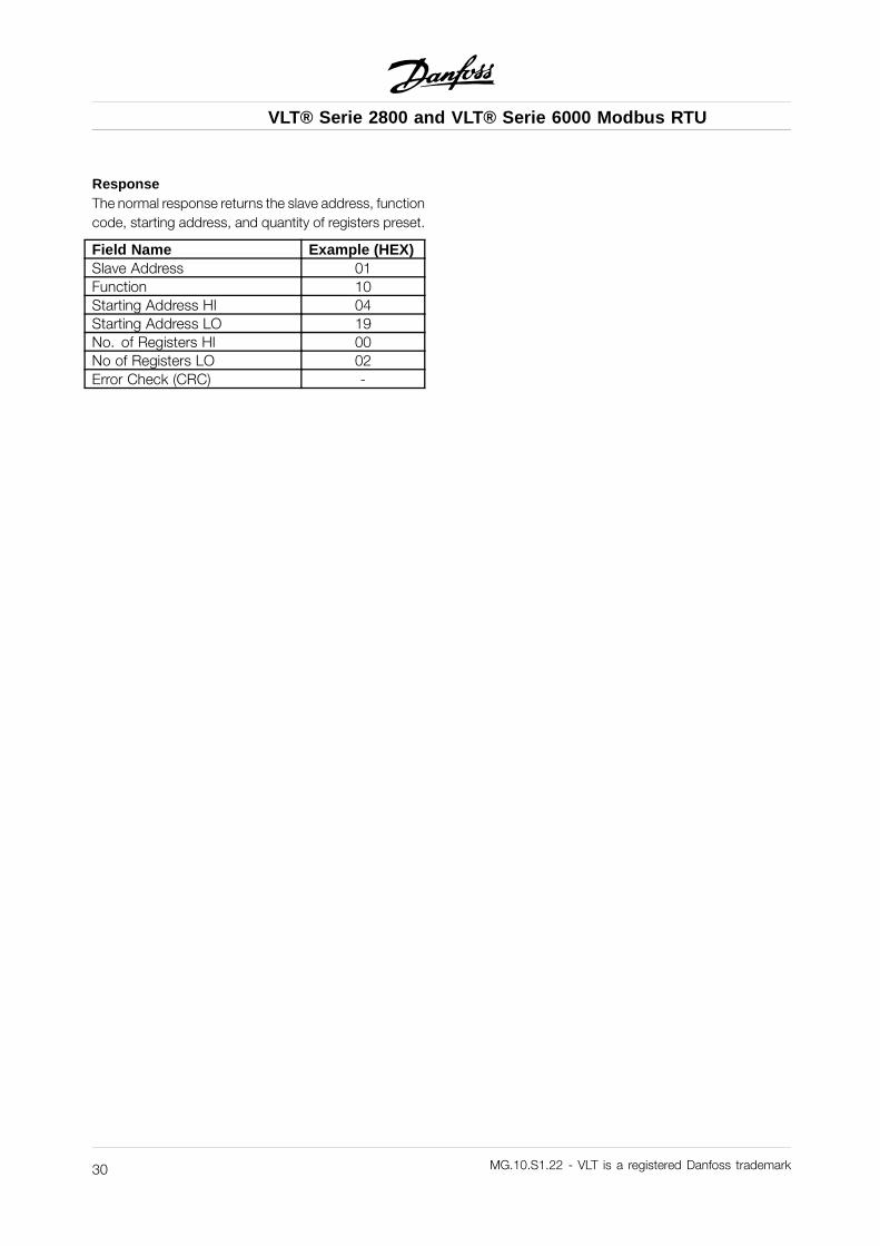
ResponseThe normal response returns the slave address, functioncode, starting address, and quantity of registers preset.
Field Name Example (HEX)Slave Address 01Function 10Starting Address HI 04Starting Address LO 19No. of Registers HI 00No of Registers LO 02Error Check (CRC) -
MG.10.S1.22 - VLT is a registered Danfoss trademark30
VLT® Serie 2800 and VLT® Serie 6000 Modbus RTU
Exc
eptio
nC
odes
åException Codes
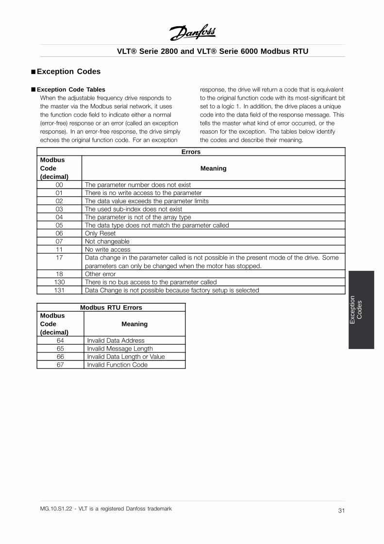
åException Code TablesWhen the adjustable frequency drive responds tothe master via the Modbus serial network, it usesthe function code field to indicate either a normal(error-free) response or an error (called an exceptionresponse). In an error-free response, the drive simplyechoes the original function code. For an exception
response, the drive will return a code that is equivalentto the original function code with its most-significant bitset to a logic 1. In addition, the drive places a uniquecode into the data field of the response message. Thistells the master what kind of error occurred, or thereason for the exception. The tables below identifythe codes and describe their meaning.
ErrorsModbusCode(decimal)
Meaning
00 The parameter number does not exist01 There is no write access to the parameter02 The data value exceeds the parameter limits03 The used sub-index does not exist04 The parameter is not of the array type05 The data type does not match the parameter called06 Only Reset07 Not changeable11 No write access17 Data change in the parameter called is not possible in the present mode of the drive. Some
parameters can only be changed when the motor has stopped.18 Other error130 There is no bus access to the parameter called131 Data Change is not possible because factory setup is selected
Modbus RTU ErrorsModbusCode(decimal)
Meaning
64 Invalid Data Address65 Invalid Message Length66 Invalid Data Length or Value67 Invalid Function Code
MG.10.S1.22 - VLT is a registered Danfoss trademark 31
VLT® Serie 2800 and VLT® Serie 6000 Modbus RTU
åAppendix A - Examples
The following examples illustrate differentModbus RTU commands.
In case of malfunction please refer to thesection Exception Codes.
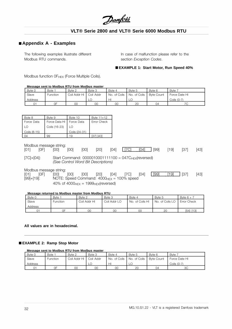
åEXAMPLE 1: Start Motor, Run Speed 40%
Modbus function 0FHEX (Force Multiple Coils).
Message sent to Modbus RTU from Modbus masterByte 0 Byte 1 Byte 2 Byte 3 Byte 4 Byte 5 Byte 6 Byte 7Slave
Address
Function Coil Addr HI Coil Addr
LO
No. of Coils
HI
No. of Coils
LO
Byte Count Force Date HI
Coils (0-7)01 0F 00 00 00 20 04 7C
Byte 8 Byte 9 Byte 10 Byte 11+12Force Data
LO
Coils (8-15)
Force Data HI
Coils (16-23)
Force Data
LO
Coils (24-31)
Error Check
04 99 19 [37] [43]
Modbus message string:[01] [0F] [00] [00] [00] [20] [04] [7C] [04] [99] [19] [37] [43]
[7C]+[04]: Start Command: 0000010001111100 = 047CHEX(reversed)(See Control Word Bit Descriptions)
Modbus message string:[01] [0F] [00] [00] [00] [20] [04] [7C] [04] [99] [19] [37] [43][99]+[19]: NOTE: Speed Command: 4000HEX = 100% speed
40% of 4000HEX = 1999HEX(reversed)
Message returned to Modbus master from Modbus RTUByte 0 Byte 1 Byte 2 Byte 3 Byte 4 Byte 5 Byte 6 + 7Slave
Address
Function Coil Addr HI Coil Addr LO No. of Coils HI No. of Coils LO Error Check
01 0F 00 00 00 20 [54] [13]
All values are in hexadecimal.
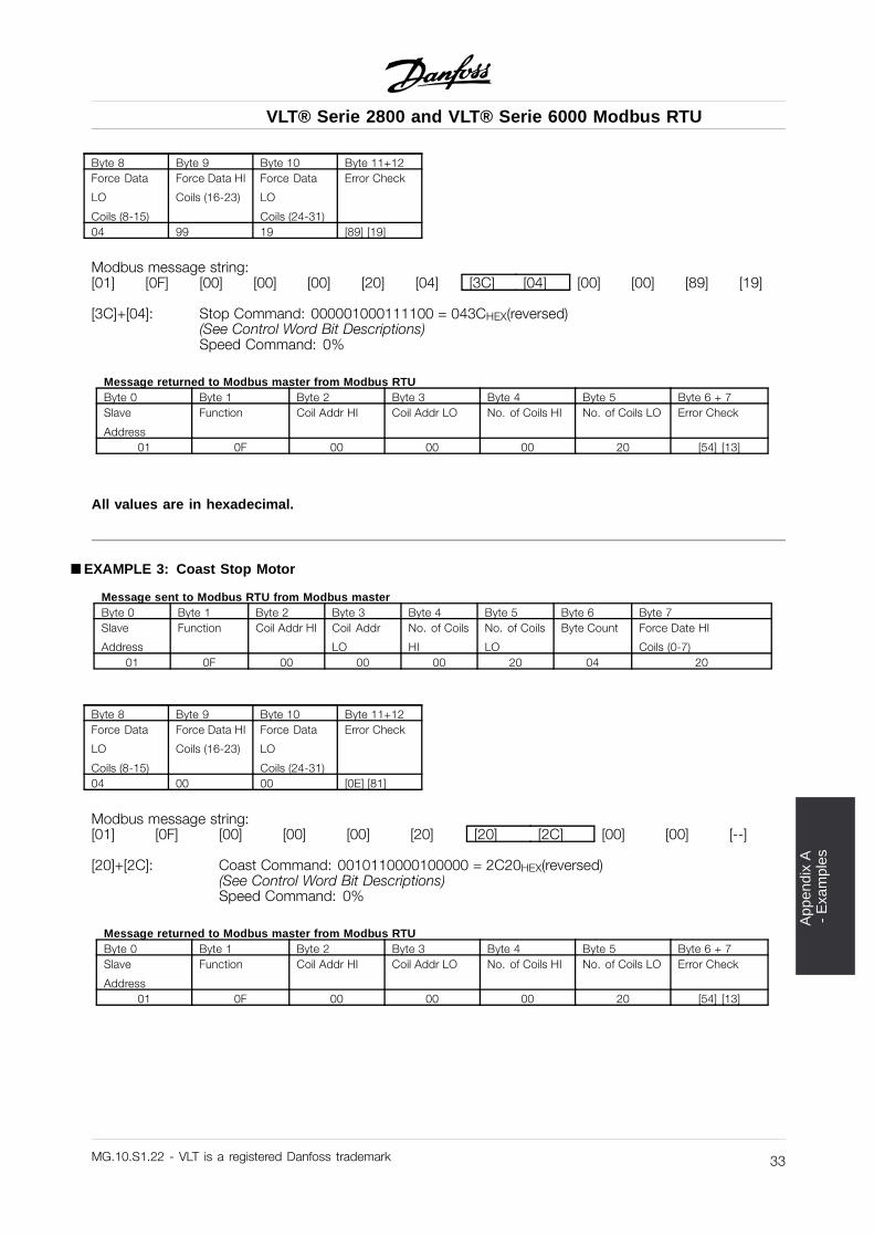
åEXAMPLE 2: Ramp Stop Motor
Message sent to Modbus RTU from Modbus masterByte 0 Byte 1 Byte 2 Byte 3 Byte 4 Byte 5 Byte 6 Byte 7Slave
Address
Function Coil Addr HI Coil Addr
LO
No. of Coils
HI
No. of Coils
LO
Byte Count Force Date HI
Coils (0-7)01 0F 00 00 00 20 04 3C
MG.10.S1.22 - VLT is a registered Danfoss trademark32
VLT® Serie 2800 and VLT® Serie 6000 Modbus RTU
App
endi
x A
-
Exa
mpl
es
Byte 8 Byte 9 Byte 10 Byte 11+12Force Data
LO
Coils (8-15)
Force Data HI
Coils (16-23)
Force Data
LO
Coils (24-31)
Error Check
04 99 19 [89] [19]
Modbus message string:[01] [0F] [00] [00] [00] [20] [04] [3C] [04] [00] [00] [89] [19]
[3C]+[04]: Stop Command: 000001000111100 = 043CHEX(reversed)(See Control Word Bit Descriptions)Speed Command: 0%
Message returned to Modbus master from Modbus RTUByte 0 Byte 1 Byte 2 Byte 3 Byte 4 Byte 5 Byte 6 + 7Slave
Address
Function Coil Addr HI Coil Addr LO No. of Coils HI No. of Coils LO Error Check
01 0F 00 00 00 20 [54] [13]
All values are in hexadecimal.
åEXAMPLE 3: Coast Stop Motor
Message sent to Modbus RTU from Modbus masterByte 0 Byte 1 Byte 2 Byte 3 Byte 4 Byte 5 Byte 6 Byte 7Slave
Address
Function Coil Addr HI Coil Addr
LO
No. of Coils
HI
No. of Coils
LO
Byte Count Force Date HI
Coils (0-7)01 0F 00 00 00 20 04 20
Byte 8 Byte 9 Byte 10 Byte 11+12Force Data
LO
Coils (8-15)
Force Data HI
Coils (16-23)
Force Data
LO
Coils (24-31)
Error Check
04 00 00 [0E] [81]
Modbus message string:[01] [0F] [00] [00] [00] [20] [20] [2C] [00] [00] [--]
[20]+[2C]: Coast Command: 0010110000100000 = 2C20HEX(reversed)(See Control Word Bit Descriptions)Speed Command: 0%
Message returned to Modbus master from Modbus RTUByte 0 Byte 1 Byte 2 Byte 3 Byte 4 Byte 5 Byte 6 + 7Slave
Address
Function Coil Addr HI Coil Addr LO No. of Coils HI No. of Coils LO Error Check
01 0F 00 00 00 20 [54] [13]
MG.10.S1.22 - VLT is a registered Danfoss trademark 33
VLT® Serie 2800 and VLT® Serie 6000 Modbus RTU
All values are in hexadecimal.
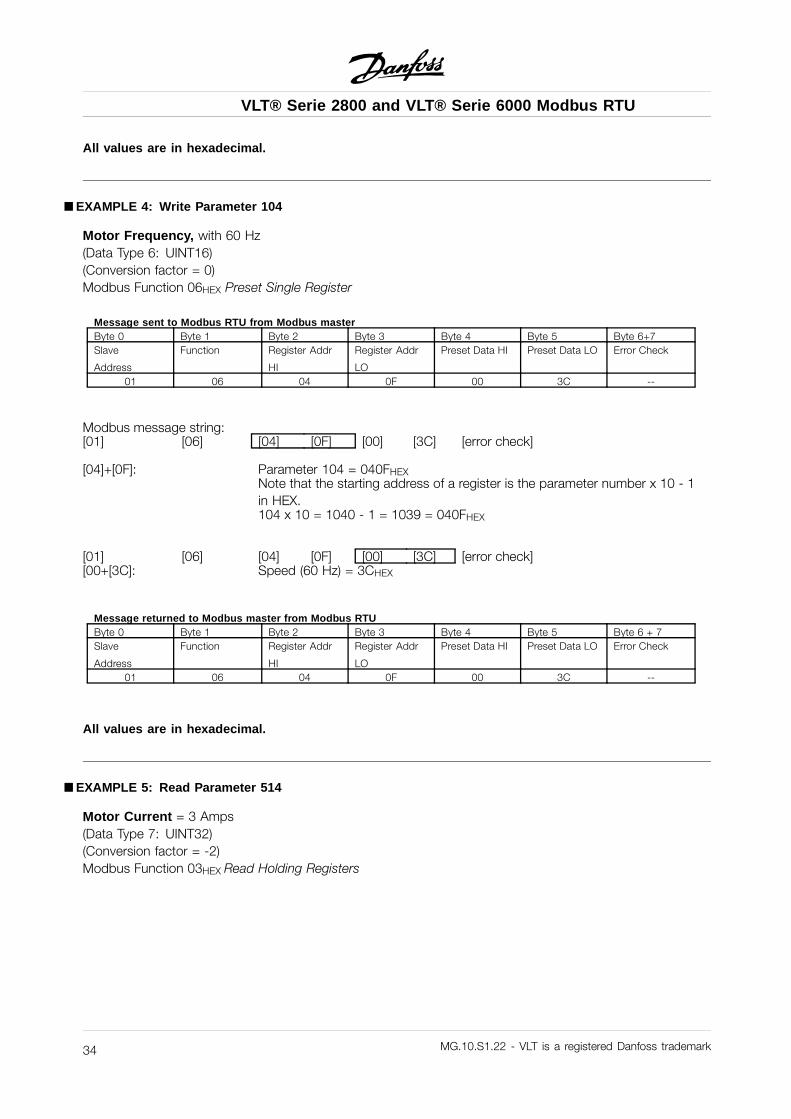
åEXAMPLE 4: Write Parameter 104
Motor Frequency, with 60 Hz(Data Type 6: UINT16)(Conversion factor = 0)Modbus Function 06HEX Preset Single Register
Message sent to Modbus RTU from Modbus masterByte 0 Byte 1 Byte 2 Byte 3 Byte 4 Byte 5 Byte 6+7Slave
Address
Function Register Addr
HI
Register Addr
LO
Preset Data HI Preset Data LO Error Check
01 06 04 0F 00 3C --
Modbus message string:[01] [06] [04] [0F] [00] [3C] [error check]
[04]+[0F]: Parameter 104 = 040FHEXNote that the starting address of a register is the parameter number x 10 - 1in HEX.104 x 10 = 1040 - 1 = 1039 = 040FHEX
[01] [06] [04] [0F] [00] [3C] [error check][00+[3C]: Speed (60 Hz) = 3CHEX
Message returned to Modbus master from Modbus RTUByte 0 Byte 1 Byte 2 Byte 3 Byte 4 Byte 5 Byte 6 + 7Slave
Address
Function Register Addr
HI
Register Addr
LO
Preset Data HI Preset Data LO Error Check
01 06 04 0F 00 3C --
All values are in hexadecimal.
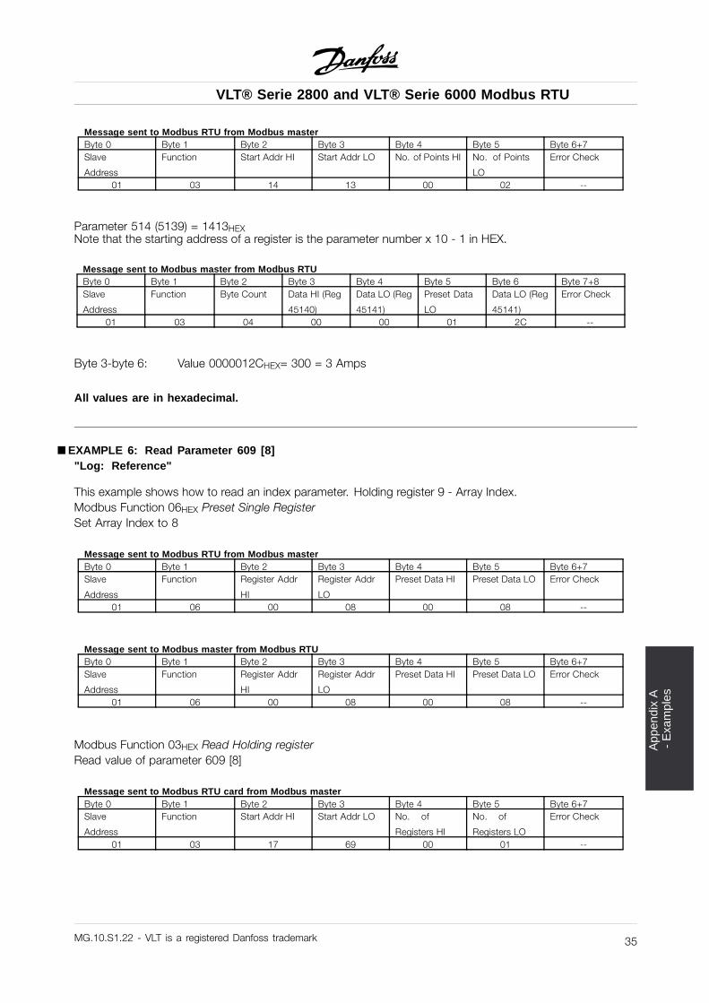
åEXAMPLE 5: Read Parameter 514
Motor Current = 3 Amps(Data Type 7: UINT32)(Conversion factor = -2)Modbus Function 03HEX Read Holding Registers
MG.10.S1.22 - VLT is a registered Danfoss trademark34
VLT® Serie 2800 and VLT® Serie 6000 Modbus RTU
App
endi
x A
-
Exa
mpl
es
Message sent to Modbus RTU from Modbus masterByte 0 Byte 1 Byte 2 Byte 3 Byte 4 Byte 5 Byte 6+7Slave
Address
Function Start Addr HI Start Addr LO No. of Points HI No. of Points
LO
Error Check
01 03 14 13 00 02 --
Parameter 514 (5139) = 1413HEXNote that the starting address of a register is the parameter number x 10 - 1 in HEX.
Message sent to Modbus master from Modbus RTUByte 0 Byte 1 Byte 2 Byte 3 Byte 4 Byte 5 Byte 6 Byte 7+8Slave
Address
Function Byte Count Data HI (Reg
45140)
Data LO (Reg
45141)
Preset Data
LO
Data LO (Reg
45141)
Error Check
01 03 04 00 00 01 2C --
Byte 3-byte 6: Value 0000012CHEX= 300 = 3 Amps
All values are in hexadecimal.
åEXAMPLE 6: Read Parameter 609 [8]"Log: Reference"
This example shows how to read an index parameter. Holding register 9 - Array Index.Modbus Function 06HEX Preset Single RegisterSet Array Index to 8
Message sent to Modbus RTU from Modbus masterByte 0 Byte 1 Byte 2 Byte 3 Byte 4 Byte 5 Byte 6+7Slave
Address
Function Register Addr
HI
Register Addr
LO
Preset Data HI Preset Data LO Error Check
01 06 00 08 00 08 --
Message sent to Modbus master from Modbus RTUByte 0 Byte 1 Byte 2 Byte 3 Byte 4 Byte 5 Byte 6+7Slave
Address
Function Register Addr
HI
Register Addr
LO
Preset Data HI Preset Data LO Error Check
01 06 00 08 00 08 --
Modbus Function 03HEX Read Holding registerRead value of parameter 609 [8]
Message sent to Modbus RTU card from Modbus masterByte 0 Byte 1 Byte 2 Byte 3 Byte 4 Byte 5 Byte 6+7Slave
Address
Function Start Addr HI Start Addr LO No. of
Registers HI
No. of
Registers LO
Error Check
01 03 17 69 00 01 --
MG.10.S1.22 - VLT is a registered Danfoss trademark 35
VLT® Serie 2800 and VLT® Serie 6000 Modbus RTU
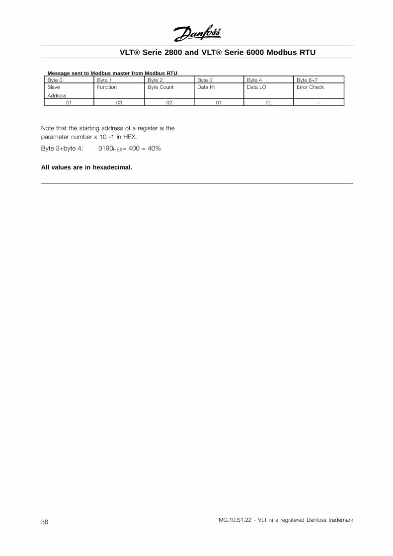
Message sent to Modbus master from Modbus RTUByte 0 Byte 1 Byte 2 Byte 3 Byte 4 Byte 6+7Slave
Address
Function Byte Count Data HI Data LO Error Check
01 03 02 01 90 --
Note that the starting address of a register is theparameter number x 10 -1 in HEX.
Byte 3+byte 4: 0190HEX= 400 = 40%
All values are in hexadecimal.
MG.10.S1.22 - VLT is a registered Danfoss trademark36