vlt® automationdrive for marine winch...
TRANSCRIPT

VLT® AutomationDrivefor marine winch applications
Application Paper
This Application Paper is meant to be a guideline for using Danfoss VLT® AutomationDrive in winch applications. The idea is to describe what to take into consideration for winch applications, and also to be an easy guideline for commissioning.
Application descriptionWinches are used onboard all ships for various operations.
Typical use is heave-up and let-out equipment, for example a
ship’s anchor, fishing trawls or hauling in mooring lines when
securing the ship to a pier. Winches come in a broad variety
of designs and sizes whether it is for towing or tugging,
anchor handling for positioning of oil rig anchors, sub sea
operations or oceanographic research. However the main
elements such as the drum, brakes, clutch, gear and electrical
motor have many similarities across the different designs.
Increased environmental awareness is becoming more and
more decisive for the type of equipment ship owners are
choosing for their vessels. A result of this is the increased
demand for electrical driven winches.
Most manufacturers of winches offer both hydraulic and
electric alternatives. Electric driven winches provide several
advantages such as; substantial energy saving (up to 30%),
no risk of hydraulic oil leaks, no piping, low operation
noise and reduced maintenance cost. Excellent speed and
tension control and advanced mechanical brake control that
ease mechanical stress on both gear and brakes are other
benefits.
This application note describes the five most common motor
configurations; single motor with and without encoder,
single/ dual drives and dual motors with and without
encoder, examples including installation diagram, all needed
parameters and typical settings.
www.vlt-marine.danfoss.com

2 Danfoss VLT Drives · DKDD.PM.301.A3.02
1
2
9
10
3
7
4
5
6
8
Here shown by the example of a combination winch.
1 Frequency converter2 Anchor chain3 Wire4 Pulley5 Manual holding brake
6 Clutch7 Encoder8 Electromechanical brake9 Motor
10 Gear box
Winch – main elements

3Danfoss VLT Drives · DKDD.PM.301.A3.02
Single motor without feedback
Typical applications:Anchor windlass
Capstan winches
Tugger winches
Fishing equipment winches
Mooring winches
Parameter set-up and wiring:see appendix 1.1 and 1.2
VVC+ Flux sensorless
Easy commissioning Robust - no encoder
Robust - no encoder High torque at low speed
Motor performance is normally OK with motor nameplate information Handles shock load better than VVC+
Can work with less accurate advanced motor data (factory settings) Starting torque higher than VVC+ mode
No adjustment of speed PID controller needed
Better regulation in the over synchronous range Embedded mechanical brake handling
Embedded mechanical brake handling
Embedded tension control feature allows rendering with calculated or feedback torque
Intertia compensated torque readout
Speed monitoring with load catch
Parameter setup see appendix 1.1 Parameter setup see appendix 1.2
Strength
VVC+ Flux open loop control
Torque control does not work
Cannot handle shock load as well as fl ux control
Cannot be used in application where rendering is expected *
Holding torque at low RPM is unsecure More accurate advanced motor data necessary than VVC+ (AMA values)
Start delay needed to magnetize the motor and open the brake relay Speed PID adjustment might be needed
Limited torque control range
Torque cannot shift from motoric to generatoric mode during running
Starting torque is dependent on motor temperature (weather condition)
Weaknesses
* Rendering is a winch feature for vessel applications such as mooring or subsea trenching. The winch is confi gured so that the winch rope will pull from the winch drum in the event that any external load becomes too great for the rated winch capacity thus preventing the winch from damage.

4 Danfoss VLT Drives · DKDD.PM.301.A3.02
Flux with motor feedback
Full holding torque at 0 RPM
Fast speed response (after temporary torque overload)
Accurate torque control
Possible to move from one quadrant to another thru 0 RPM
Possible to use tracking error function = supervision of speed
Better control of the electromechanical brake function
Embedded tension control feature allows rendering with calculated or feedback torque
Intertia compensated torque readout
Speed monitoring with load catch
Parameter setup see appendix 2.2
Strength
Weaknesses
Flux vector closed loop control
More accurate advance motor data necessary (AMA values)
Speed PID adjustment might be needed
Lack of voltage in the fi eld weakening range
Typical applications:Offshore winches - active heave compensation
Mooring winches - compensation for
high/low tidal water or loading/unloading
Mooring winches with tension sensors
Parameter set-up and wiring:see appendix 2.1 and 2.2
Single motor with feedback

5Danfoss VLT Drives · DKDD.PM.301.A3.02
U/f mode or VVC+ with open loop control
All motors in parallel connected to only one large frequency converter
Probably most economical solution for 2 motors
Multiple motors used due to limited space
Asynchronous motors with high slip provide natural load sharing capability
Share gear box load
Redundancy if one motor fail
Fairly simple set up and control (all motors are the same size = multiplying of motor current values)
U/f motor mode does not need advanced motor parameters
Embedded tension control feature allows rendering with calculated or feedback torque
Intertia compensated torque readout
Speed monitoring with load catch
Parameter setup see appendix 3.1
Strength
U/f mode or VVC+ with open loop control
No redundancy if the frequency converter fails
Practical useful only for motors with fairly high slip = mainly smaller motors (motors with equal torque curves are available at small extra cost)
High effi ciency motors with low slip do not provide good load sharing
No slip compensation in U/f mode
Weaknesses
Multiple motors and single drive without feedback
Typical applications:Anchor windlass
Capstan winches
Tugger winches
Fishing equipment winches
Mooring winches
Parameter set-up and wiring:see appendix 3.1

6 Danfoss VLT Drives · DKDD.PM.301.A3.02
Typical applications:Capstan winches
Tugger winches
Fishing equipment winches
Parameter set-up and wiring:see appendix 4.1 and 4.2
Multiple motors and multiple drives without feedback
Strength
VVC+ open loop control Flux vector open loop control
Simple set up by using negative slip compensation
Works even when one drive/motor fails
One frequency converter for each motor
Useful with limited space for one large motor
Larger asynchronous motors with small slip can load share with negative slip compensation
High effi cient motors with small slip can work with negative slip compensation
Redundancy if one motor/frequency converter fails
Fairly simple set up and control in VVC+ or fl ux sensorless mode (common speed reference signal for both frequency converters).
Parameter setup see appendix 4.1 Parameter setup see appendix 4.2
Weaknessess
VVC+ open loop control Flux vector open loop control
Can not be used where rendering is expected
The motors have to be equal
Speed is reduced with increasing load
All motors must have the same power size (and torque curve).
Start up and low RPM speed require careful parameter adjustment (possibility for regenerative mode if one system drives the other).

7Danfoss VLT Drives · DKDD.PM.301.A3.02
Strength
Flux vector closed loop control
Can be used in applications with rendering
Excellent electromechanical brake control
Normally the motors are equal in power size = equal load sharing with equal slip; but deviation can be compensated
Working in motoring as well as in regenerative mode
High torque available, also at 0 speed
Redundancy available, both electrical or mechanical, should one motor/frequency converter fail
Multiple drives will share the torque optimal
Easy programming, all drives have same programs
No communication needed between masters
Droop with speed trim possible
Embedded tension control feature allows rendering with calculated or feedback torque
Intertia compensated torque readout
Speed monitoring with load catch
Parameter setup see appendix 5.1
Only to be run in fl ux vector mode closed loop and with software SW xxx or higher with droop
Typical applications:Offshore winches - active heave compensation
Remote Operated Vehicle
Anchor handling tug winch
Deep sea winches
Parameter set-up and wiring:see appendix 5.1
Multiple motors and multiple drives with or without motor feedback (2)Droop concept

8 Danfoss VLT Drives · DKDD.PM.301.A3.02 Danfoss VLT Drives · DKDD.PM.301.A3.02
Appendix 1.1
Single motor without feedback VVC+ openloop control
Wiring
U 82V W 81
02
01
M
PE PE
L1 L2 L3 PE
12 (+24V)
19 (Start CCW)
18 (Start CW)
Speed ref.2.2 kOhm
Torque ref.2.2 kOhm
50 (+10 V)
53 (0-10 V)
54 (0-10 V)
55 (COM)
FC 302
CW stop CCW

9Danfoss VLT Drives · DKDD.PM.301.A3.02
Parameter set-up – Single motor without feedback VVC+ open loop control
Par. ID Parameter name Drive Comment ( * = factory settings)
1-00 Confi guration Mode Speed open loop *
1-01 Motor Control Principle VVC+ * (include V/A comp. and slip comp.)
1-03 Torque Characteristics Constant torque *
1-04 Overload Mode High Torque * (150-160% over current available)
1-06 Clockwise Direction Normal * (avoid using this parameter).
1-10 Motor Construction Asynchron * (no PM motor considered here)
1-201-26
Motor Data inserted Motor size = Drive size (150-160% over current available)
1-29 Automatic Motor Adaptation Use complete AMA For larger Drive use reduced AMA
1-301-37
Advanced motor data is calculated based on motor data
R1 = stator resistanceXh = main impedance.
R1 should also include cable resistance.Xh determine magnetizing current.
1-39 Motor Poles Automatic calculated Calculated based on par. 1-23 and 1-25.Never use synchron speed for par. 1-25.
1-501-52
Magnetizing current at low speed * Use factory settings.
1-601-61
Low Speed and High Speed Compensation (V/A comp.)
* Use factory Settings.
1-62 Slip Compensation 100% = Constant speed in open loop.* Use factory settings. But reduce % in case of unstable operation.
1-64 Resonance Dampening 100% = Normal damping.Resonance damping is based on motor slip. Par.1-23 and par. 1-25. Unstable operation: increase or reduce parameter
1-71 Start Delay 0.1 – 1.5 second. Time needed to magnetize the motor
1-72 Start Function VVC+/fl ux clockwiseVVC+ can ramp up, but not provide motor torque before magnetized.
1-74 Start Speed Use slip in RPMAfter start delay time can the motor provide 100 % nominal torque.
1-80 Function at Stop Coast *
1-81 Min. Speed for Function at Stop 2-3 RPM
1-90 Motor Thermal Protection ETR warning 1 ETR does not require external sensors.
2-10 Brake Function Resistor Brake.Most application require a brake resistor. Large resistors can be water cooled.
2-11 Brake resistor Use factory size. Give 160% generatoric torque
2-12 Brake power limit Use brake information. Average value for the resistor.
2-13 Brake Power Monitoring. Warning. Use as indication for overheating.
2-15 Brake check Warning. Indication for brake failure.
2-18 Brake Check Condition After Coast Situation Additional brake check.
2-20 Release Brake Current Use magnetizing current for the motorWhen the actual current is above the set current within the start delay time, then mechanical brake relay change state.
2-21 Activate Brake Speed Set RPM for closingDetermine physical closing time for the brake. Determine the ramp down time. Calculate the set RPM for closing the brake at 0 RPM.
2-23 Activate Brake Delay 0.1 – 0.5 secondActivate a holding torque, after the brake has closed. Taking care of time delay for worn brake lining.
Par. ID Parameter name Drive Comment ( * = factory settings)
3-40 Ramp 1 Type Linear* Other ramp types might be better, but can extend actual time.
3-41 Ramp 1. Ramp up time As neededRamp time = time from 0 RPM to synchronous speed. Too short time may activate current /torque warning.
3-42 Ramp 1. Ramp down time As neededRamp time = time from synchronous speed to 0 RPM. Too short time may activate current /torque warning.
4-10 Motor Speed Direction Both directions Winch normally need both directions
4-13 Motor Speed High Limit As needed Lower to max. needed (+ 2 x slip).
4-16 Torque Limit Motor Mode 160% * (suggestion: 15% higher than current limit)
4-17 Torque Limit Generator Mode 160% (suggestion: 15% higher than current limit)
4-18 Current limit Max. % % = Max. current for drive / nominal current for motor.
4-19 Max Output Frequency As needed Slightly higher than parameter 4-13.

10 Danfoss VLT Drives · DKDD.PM.301.A3.02
Par. ID Parameter name Drive Comment ( * = factory settings)
5-11 Terminal 19 Digital Input Start reversingDigital input normally provided by joystick with only one direction signal.
5-40 Function Relay Mechanical brake ctrl.Relay 1 is normally used for this function. Take care of contact burning.
5-41 On Delay, Relay 0.0 – 1.4 secondIf the magnetizing time of the motor is longer than the release time of the brake.
5-42 Off Delay, Relay 0.0 second * Normally not used.
6-00 Live Zero Timeout Time 1 second Use where 4-20 mA signal is present.
6-01 Live Zero Timeout Function Stop and trip. Function if reference is lost.
14-00 Switching pattern SFAVM* Normally best choice regarding performance and acoustic noise.
14-01 Switching Frequency* Switching frequency higher than factory settings might decrease thermal performance for the drive.
14-03 Overmodulation * give higher voltage for VVC+ in over synchronous range.
14-10 Mains Failure Ctrl. ramp down This setting is best choice, but might not work for VVC+.
14-11 Mains Voltage at Mains Fault. As needed Set to 10% below min. mains level.
14-12 Function at Mains Imbalance Warning.Factory setting is trip. A generator supply might activate this trip too often.
14-24 Trip Delay at Current Limit As neededRunning too long in current limit indicate something is overloaded.
14-25 Trip Delay at Torque Limit As neededRunning too long in torque limit indicate something is overloaded.
14-26 Trip Delay at Inverter Fault 0 second Too high voltage = brake faulty.
14-50 RFI Filter Off Factory setting is ON. For IT grids use OFF. For TN grids use ON.
14-90 Fault Level Off * Should not be used ; but fault condition can be changed.
Parameter set-up – Single motor without feedback VVC+ open loop control

11Danfoss VLT Drives · DKDD.PM.301.A3.02
Appendix 1.2
Single motor without feedback Flux vector open loop control
Wiring
U 82V W 81
02
01
M
PE PE
L1 L2 L3 PE
12 (+24V)
19 (Start CCW)
18 (Start CW)
Speed ref.2.2 kOhm
Torque ref.2.2 kOhm
50 (+10 V)
53 (0-10 V)
54 (0-10 V)
55 (COM)
FC 302
CW stop CCW

12 Danfoss VLT Drives · DKDD.PM.301.A3.02
Parameter set-up – Single motor without feedback Flux vector open loop control
Par. ID Parameter name Drive Comment ( * = factory settings)
1-00 Confi guration Mode Speed open loop *
1-01 Motor Control Principle Flux sensorless * (include slip comp.)
1-03 Torque Characteristics Constant torque *
1-04 Overload Mode High Torque * (150-160% over current available)
1-06 Clockwise Direction Normal * (avoid using this parameter).
1-10 Motor Construction Asynchron * (no PM motor considered here)
1-201-26
Motor Data inserted Motor size = Drive size (150-160% over current available)
1-29 Automatic Motor Adaptation Use complete AMA For larger Drive use reduced AMA
1-301-37
Advanced motor data is calculated based on motor data
R1 = stator resistanceXh = main impedance
R1 should also include cable resistanceXh determine magnetizing current
1-39 Motor Poles Automatic calculatedCalculated based on par. 1-23 and 1-25.Never use synchron speed for par. 1-25.
1-53 Model Shift Frequency * Use factory settings, or about 15% of nominal frequency.
1-54Voltage reduction in Field- weak-ening
0 Volt* Use factory Settings. Can be increased if voltage is missing in over synchronous range.
1-62 Slip Compensation !00% = Constant speed in open loop.* use factory settings. But reduce % in case of unstable operation.
1-64 Resonance Dampening 100% = Normal damping.Resonance damping is based on motor slip. Par.1-23 and par. 1-25. Unstable operation: increase or reduce parameter
1-66 Min. Current at Low Speed 100%* 100% = low current is = nominal current. Change if needed.
1-67 Load Type Active Load Enhance the performance at low RPM.
1-71 Start Delay 0.1 – 2.0 second.Time to indicate that current is present for the motor and above parameter 2-20
1-72 Start Function VVC+/fl ux clockwise Will calculate right current for output frequency.
1-74 Start Speed Use slip in RPM Can provide 100 % torque by star
1-80 Function at Stop Coast *
1-81 Min. Speed for Function at Stop 2-3 RPM
1-90 Motor Thermal Protection ETR warning 1 ETR does not require external sensors.
2-10 Brake Function Resistor Brake.Most application require a brake resistor. Large resistors can be water cooled.
2-11 Brake resistor Use factory size. Give 160% generatoric torque
2-12 Brake power limit Use brake information. Average value for the resistor.
2-13 Brake Power Monitoring. Warning. Use as indication for overheating.
2-15 Brake check Warning. Indication for brake failure.
2-18 Brake Check Condition After Coast Situation Additional brake check.
2-20 Release Brake Current Use magnetizing current for the motorWhen the actual current is above the set current within the start delay time, then mechanical brake relay change state.
2-21 Activate Brake Speed Set RPM for closingDetermine physical closing time for the brake. Determine the ramp down time. Calculate the set RPM for closing the brake at 0 RPM.
2-23 Activate Brake Delay 0.1 – 0.5 secondActivate a holding torque, after the brake has closed. Taking care of time delay for worn brake lining.
3-40 Ramp 1 Type Linear* Other ramp types might be better, but can extend actual time.
3-41 Ramp 1. Ramp up time As neededRamp time = time from 0 RPM to synchronous speed. Too short time may activate current /torque warning.
3-42 Ramp 1. Ramp down time As neededRamp time = time from synchronous speed to 0 RPM. Too short time may activate current /torque warning.
4-10 Motor Speed Direction Both directions Winch normally need both directions
4-13 Motor Speed High Limit As needed Lower to max. needed (+ 2 x slip).
4-16 Torque Limit Motor Mode 160% * (suggestion: 15% higher than current limit)
4-17 Torque Limit Generator Mode 160% (suggestion: 15% higher than current limit)
4-18 Current limit Max. % % = Max. current for drive / nominal current for motor.
4-19 Max Output Frequency As needed Slightly higher than parameter 4-13.
5-11 Terminal 19 Digital Input Start reversingDigital input normally provided by joystick with only one direction signal.

13Danfoss VLT Drives · DKDD.PM.301.A3.02
Par. ID Parameter name Drive Comment ( * = factory settings)
5-40 Function Relay Mechanical brake ctrl.Relay 1 is normally used for this function. Take care of contact burning.
5-41 On Delay, Relay 0.0 – 1.0 secondAdjust the brake to be open, when the drive start to ramp up.
5-42 Off Delay, Relay 0.0 second * Normally not used.
6-00 Live Zero Timeout Time 1 second Use where 4-20 mA signal is present.
6-01 Live Zero Timeout Function Stop and trip. Function if reference is lost.
6-15Terminal 53 High ref/(feedback) Value
As needed Reference for 20 mA or 10 Volt.
N.B. Set control card switch for I or V Current or voltage input See settings in parameter 16-61.
7-02 Speed PID Proportional Gain 0.015* Should be adjusted. Normally a higher gain is necessary; but take care of instability.
7-03 Speed PID Integral Time 200ms* factory setting is normally O.K. ; but could be reduced for better dynamic operation. Take care of instability.
7-04 Speed PID Diff erentiation Time Off * Normally not used. If set, take care of instability above 1 ms.
14-00 Switching pattern SFAVM* Normally best choice regarding performance and acoustic noise.
14-01 Switching Frequency* Switching frequency higher than factory settings might decrease thermal performance for the drive.
14-10 Mains Failure Ctrl. ramp down This setting is best choice
14-11 Mains Voltage at Mains Fault. As needed Set to 10% below min. mains level.
14-12 Function at Mains Imbalance Warning.Factory setting is trip. A generator supply might activate this trip too often.
14-24 Trip Delay at Current Limit As neededRunning too long in current limit indicate something is overloaded.
14-25 Trip Delay at Torque Limit As neededRunning too long in torque limit indicate something is overloaded.
14-26 Trip Delay at Inverter Fault 0 second Too high voltage = brake faulty.
14-50 RFI Filter Off Factory setting is ON. For IT grids use OFF. For TN grids use ON
14-90 Fault Level Off * Should not be used ; but fault condition can be changed.
Parameter set-up – Single motor without feedback Flux vector open loop control

14 Danfoss VLT Drives · DKDD.PM.301.A3.02
Appendix 2.1
Single motor with feedback VVC+ closedloop control
Wiring
MCB 102
U 82V W 81
02
01
M
PE PE
L1 L2 L3 PE
+
GND
A+
A-
B+
B-
Torque ref.2.2 kOhm
50 (+10 V)
53 (0-10 V)
54 (0-10 V)
55 (COM)
FC 302
Speed ref.2.2 kOhm
12 (24V)
18 (start cw)
19 (start ccw)

15Danfoss VLT Drives · DKDD.PM.301.A3.02
Par. ID Parameter name Drive Comment ( * = factory settings)
1-00 Confi guration Mode Speed closed loop
1-01 Motor Control Principle VVC+ * (include V/A comp.)
1-03 Torque Characteristics Constant torque *
1-02
1-04 Overload Mode High Torque * (150-160% over current available)
1-06 Clockwise Direction Normal * (avoid using this parameter).
1-10 Motor Construction Asynchron * (no PM motor considered here)
1-201-26
Motor Data inserted Motor size = Drive size (150-160% over current available)
1-29 Automatic Motor Adaptation Use complete AMA For larger Drive use reduced AMA
1-301-37
Advanced motor data is calculated based on motor data
R1 = stator resistanceXh = main impedance.
R1 should also include cable restistanceXh determine magnetizing current.
1-39 Motor Poles Automatic calculated Calculated based on par. 1-23 and 1-25.Never use synchron speed for par. 1-25.
1-501-52
Magnetizing current at low speed * Use factory settings.
1-601-61
Low Speed and High Speed Compensation (V/A comp.)
* Use factory Settings.
1-64 Resonance Dampening 100% = Normal damping.Resonance damping is based on motor slip. Par.1-23 and par. 1-25. Unstable operation: increase or reduce parameter
1-71 Start Delay 0.1 – 1.5 second. Time needed to magnetize the motor
1-72 Start Function VVC+/fl ux clockwiseVVC+ can ramp up, but not provide motor torque before magnetized.
1-74 Start Speed Use slip in RPMAfter start delay time can the motor provide 100 % nominal torque.
1-80 Function at Stop Coast *
1-81 Min. Speed for Function at Stop 2-3 RPM
1-90 Motor Thermal Protection ETR warning 1 ETR does not require external sensors.
2-10 Brake Function Resistor Brake.Most application require a brake resistor. Large resistors can be water cooled.
2-11 Brake resistor Use factory size. Give 160% generatoric torque
2-12 Brake power limit Use brake information. Average value for the resistor.
2-13 Brake Power Monitoring. Warning. Use as indication for overheating.
2-15 Brake check Warning. Indication for brake failure.
2-18 Brake Check Condition After Coast Situation Additional brake check.
2-20 Release Brake Current Use magnetizing current for the motorWhen the actual current is above the set current within the start delay time, then the mechanical brake relay change state.t
2-21 Activate Brake Speed Set RPM for closingDetermine physical closing time for the brake. Determine the ramp down time.Calculate the set RPM for closing the brake at 0 RPM.
2-23 Activate Brake Delay 0.1 – 0.5 secondActivate a holding torque, after the brake has closed. Taking care of time delay for worn brake lining.
3-40 Ramp 1 Type Linear* Other ramp types might be better, but can extend actual time.
3-41 Ramp 1. Ramp up time As neededRamp time = time from 0 RPM to synchronous speed. Too short time may activate current /torque warning.
3-42 Ramp 1. Ramp up time As neededRamp time = time from synchronous speed to 0 RPM. Too short time may activate current /torque warning.
4-10 Motor Speed Direction Both directions Winch normally need both directions
4-13 Motor Speed High Limit As needed Lower to max. needed (+ 2 x slip).
4-16 Torque Limit Motor Mode 160%* (suggestion: 15% higher than current limit). Give true limit also in over synchronous range.
4-17 Torque Limit Generator Mode 160% (Suggestion: 15% higher than current limit). Give true limit also in over synchronous range.
Parameter set-up – Single motor with feedback VVC+ closed loop control

16 Danfoss VLT Drives · DKDD.PM.301.A3.02
Par. ID Parameter name Drive Comment ( * = factory settings)
4-18 Current limit Max. % % = Max. current for drive / nominal current for motor.
4-19 Max Output Frequency As needed Slightly higher than parameter 4-13.
4-30 Motor Feedback Loss function Warning (switch to open loop)Suggestion is Warning. Alternative setting is Switch to open loop, when output frequency = diff erent from ref.
4-31 Motor Feedback Speed Error 300 RPM * This window is motor dependent.
4-32 Motor feedback Loss Timeout 1 second Factory setting of 0.05 second might be too fast.
4-34 Tracking Error Function Warning.
4-35 Tracking Error 100 RPM Factory setting of 10 RPM is too small window.
4-36 Tracking Error Timeout 1 second *
4-37 Tracking Error Ramping 100 RPM * Might be increased to 200 RPM if too sensitive.
4-38 Tracking Error Ramping Timeout. 5 second* Could be decreased to about 1 second for a faster detection.
5-11 Terminal 19 Digital Input Start reversingDigital input normally provided by joystick with only one direction signal.
5-40 Function Relay Mechanical brake ctrl.Relay 1 is normally used for this function. Take care of contact burning.
5-41 On Delay, Relay 0.0 – 1.4 secondIf the magnetizing of the motor is longer than the opening of the brake.
5-42 Off Delay, Relay 0.0 second * Normally not used.
5-70 Term 32/33 Pulses per revolution 1024* Many encoders are with 1024 pulses, use factory settings, otherwise adjust.
5-71 Term 32/33 Encoder Direction. Clockwise* If over current or tracking error is present at start, then encoder direction most likely is wrong, change settings.
6-00 Live Zero Timeout Time 1 second Use where 4-20 mA signal is present.
6-01 Live Zero Timeout Function Stop and trip. Function if reference is lost.
6-15Terminal 53 High ref/(feedback) Value
As needed Reference for 20 mA or 10 Volt.
N.B. Set control card switch for I or V Current or voltage input See settings in parameter 16-61.
7-00 Speed PID Feedback Source MCB 102 option* Use 5 V encoder with MCB 102, especially with long cable lenghts
7-02 Speed PID Proportional Gain 0.015 * Can be increased. Take care of instability
7-03 Speed PID integral Time 8 ms* Can be decreased for a faster response. Take care of instability.
7-04 Speed PID Diff erentiation Time 1 msFactory setting of 30ms is far too high.Use max. 1- 2 ms for faster response.
7-06 Speed PID Lowpass Filter Time 5 msAdjust to pulses per revolution of encoder. Higher pulses = lower ms.
7-08 Speed PID Feed Forward Factor 80%Feed forward only working for VVC+, give a much faster response. Take care with too high settings, can lead to instability (avoid over 80%).
14-00 Switching pattern SFAVM* Normally best choice regarding performance and acoustic noise.
14-01 Switching Frequency* Switching frequency higher than factory settings might decrease thermal performance for the drive.
14-03 Overmodulation * give higher voltage for VVC+ in over synchronous range.
14-10 Mains Failure Ctrl. ramp down This setting is best choice, but might not work for VVC+.
14-11 Mains Voltage at Mains Fault. As needed Set to 10% below min. mains level.
14-12 Function at Mains Imbalance Warning.Factory setting is trip. A generator supply might activate this trip too often.
14-24 Trip Delay at Current Limit As neededRunning too long in current limit indicate something is overloaded.
14-25 Trip Delay at Torque Limit As neededRunning too long in torque limit indicate something is overloaded.
14-26 Trip Delay at Inverter Fault 0 second Too high voltage = brake faulty.
14-50 RFI Filter Off Factory setting is ON, but this might increase the DC voltage especially in standby mode for IT mains. Use OFF.
14-55 Output fi lter No fi lter * Set parameter if output fi lter is used.
14-90 Fault Level Off * Should not be used ; but fault condition can be changed.
Parameter set-up – Single motor with feedback VVC+ closed loop control

17Danfoss VLT Drives · DKDD.PM.301.A3.02
Appendix 2.2
Single motor with feedback Flux vector closedloop control
Wiring
MCB 102
U 82V W 81
02
01
M
PE PE
L1 L2 L3 PE
+
GND
A+
A-
B+
B-
Torque ref.2.2 kOhm
50 (+10 V)
53 (0-10 V)
54 (0-10 V)
55 (COM)
FC 302
Speed ref.2.2 kOhm
12 (24V)
18 (start cw)
19 (start ccw)

18 Danfoss VLT Drives · DKDD.PM.301.A3.02
Par. ID Parameter name Drive Comment ( * = factory settings)
1-00 Confi guration Mode Speed closed loop
1-01 Motor Control Principle Flux w/ motor feedback
1-02 Flux Motor Feedback Source MCB 102 TTL 5V encoder used for MCB 102
1-03 Torque Characteristics Constant Power Work only for fl ux closed loop.
1-04 Overload Mode High Torque * (150-160% over current available)
1-06 Clockwise Direction Normal * (avoid using this parameter).
1-10 Motor Construction Asynchron * (no PM motor considered here)
1-201-26
Motor Data inserted Motor size = Drive size (150-160% over current available)
1-29 Automatic Motor Adaptation Use complete AMA For larger Drive use reduced AMA
1-301-37
Advanced motor data is calculated based on motor data
R1 = stator resistanceXh = main impedance
R1 should also include cable resistanceXh determine magnetizing current
1-39 Motor Poles Automatic calculatedCalculated based on par. 1-23 and 1-25Never use synchron speed for par. 1-25
1-53 Model Shift Frequency* Use factory setting. Otherwise use 15% of nominal motor frequency
1-54Voltage reduction in Fieldweaken-ing
0V* Use factory setting. In case of warning 62 try to reduce the voltage.
1-71 Start Delay 0 second * Disappear with settings in P1-72.
1-72 Start Function Hoist Mech. Brake Relay Special setting for fl ux closed loop.
1-76 Start Current 0.0 Amp. *No use in fl ux closed loop.
1-80 Function at Stop Coast *
1-81 Min. Speed for Function at Stop 2-3 RPM
1-90 Motor Thermal Protection ETR warning 1 ETR does not require external sensors.
2-10 Brake Function Resistor BrakeMost application requires a brake resistor. Large resistors can be water cooled.
2-11 Brake resistor Use factory size. Give 160% generatoric torque
2-12 Brake power limit Use brake information. Average value for the resistor.
2-13 Brake Power Monitoring. Warning. Use as indication for overheating.
2-15 Brake check Warning. Indication for brake failure.
2-18 Brake Check Condition After Coast Situation Additional brake check.
2-21 Activate Brake Speed Set RPM for closingDetermine physical closing time for the brake. Determine the ramp down time.Calculate the set RPM for closing the brake at 0 RPM.
2-23 Activate Brake Delay 0.1 – 0.5 secondActivate a holding torque, after the brake has closed. Taking care of time delay for worn brake lining.
2-24 Stop Delay 0 second. * delay time for closing the brake relay.
2-25 Brake Release Time 0.2 second* Set as needed. Time for the brake to open. Time for increased proportional gain boost.
2-26 Torque Ref 70%Set as needed. Torque applied against closed brake before brake release.
2-27 Torque Ramp Time 0.2 second * Ramp time for parameter 2-26.
2-28 Gain boost Factor 2.00Set as needed. Increased proportional gain during time for parameter 2-25.
3-40 Ramp 1 Type Linear* Other ramp types might be better, but can extend actual time.
3-41 Ramp 1. Ramp up time As neededRamp time = time from 0 RPM to synchronous speed. Too short time may activate current /torque warning.
3-42 Ramp 1. Ramp down time As neededRamp time = time from synchronous speed to 0 RPM. Too short time may activate current /torque warning.
4-10 Motor Speed Direction Both directions Winch normally need both directions
4-13 Motor Speed High Limit As needed Lower to max. needed (+ 2 x slip).
4-16 Torque Limit Motor Mode 160%* (suggestion: 15% higher than current limit). Goes down with fi eld weakening curve, when parameter 1-03 is set for constant power.
Parameter set-up – Single motor with feedback Flux vector closed loop control

19Danfoss VLT Drives · DKDD.PM.301.A3.02
Par. ID Parameter name Drive Comment ( * = factory settings)
4-17 Torque Limit Generator Mode 160%(suggestion: 15% higher than current limit). Goes down with fi eld weakening curve, when parameter 1-03 is set for constant power.
4-18 Current limit Max. % % = Max. current for drive / nominal current for motor.
4-19 Max Output Frequency As needed Slightly higher than parameter 4-13.
4-20 Torque Limit Factor Source Analog in 54Can be used to adjust parameter 4-16 and 4-17 by remote potentiometer.
4-30 Motor Feedback Loss function Warning Suggestion is Warning.
4-31 Motor Feedback Speed Error 300 RPM * This window is motor dependent.
4-32 Motor feedback Loss Timeout 1 second Factory setting of 0.05 second might be too fast.
4-34 Tracking Error Function Warning
4-35 Tracking Error 100 RPM Factory setting of 10 RPM is too small window.
4-36 Tracking Error Timeout 1 second *
4-37 Tracking Error Ramping 100 RPM * Might be increased to 200 RPM if too sensitive.
4-38 Tracking Error Ramping Timeout. 5 second* Could be decreased to about 1 second for a faster detection.
5-11 Terminal 19 Digital Input Start reversingDigital input normally provided by joystick with only one direction signal.
5-40 Function Relay Mechanical brake ctrl.Relay 1 is normally used for this function. Take care of contact burning.
5-41 On Delay, Relay 0.01 second * Use parameter 2-25 if needed.
5-42 Off Delay, Relay 0.01 second * Normally not used.
6-00 Live Zero Timeout Time 1 second Use where 4-20 mA signal is present.
6-01 Live Zero Timeout Function Stop and trip. Function if reference is lost.
6-15Terminal 53 High ref/(feedback) Value
As needed Reference for 20 mA or 10 Volt.
N.B. Set control card switch for I or V Current or voltage input See settings in parameter 16-61.
7-00 Speed PID Feedback Source MCB 102 option.* Use 5 V encoder with MCB 102, especially with long cable lengths.
7-02 Speed PID Proportional Gain 0.015 * Can be increased. Take care of instability
7-03 Speed PID integral Time 200 ms* Can be decreased for a faster response. Take care of instability.
7-04 Speed PID Diff erentiation Time 1 ms Use max. 1- 2 ms for faster response.
7-06 Speed PID Lowpass Filter Time 5 msAdjust to pulses per revolution of encoder. Higher pulses = lower ms.
14-00 Switching pattern SFAVM* Normally best choice regarding performance and acoustic noise.
14-01 Switching Frequency* Switching frequency higher than factory settings might decrease thermal performance for the drive.
14-10 Mains Failure Ctrl. ramp down This setting is best choice, but might not work for VVC+.
14-11 Mains Voltage at Mains Fault As needed Set to 10% below min. mains level
14-12 Function at Mains Imbalance Warning.Factory setting is trip. A generator supply might activate this trip too often
14-24 Trip Delay at Current Limit As neededRunning too long in current limit indicate something is overloaded.
14-25 Trip Delay at Torque Limit As neededRunning too long in torque limit indicate something is overloaded.
14-26 Trip Delay at Inverter Fault 0 second Too high voltage = brake faulty.
14-35 Stall Protection Enable *
14-50 RFI Filter Off Factory setting is ON. For IT grids use OFF. For TN grids use ON.
14-55 Output fi lter No fi lter * Set parameter if output fi lter is used.
14-90 Fault Level Off * Should not be used ; but fault condition can be changed.
17-10 Signal Type RS 422 (5 V TTL) * Factory setting for most used encoder.
17-11 Resolution (PPR) 1024 * Factory settings for most popular PPR. Change if needed.
Parameter set-up – Single motor with feedback Flux vector closed loop control

20 Danfoss VLT Drives · DKDD.PM.301.A3.02
Appendix 3.1
Multiple motors and single drive without feedback – Special motor mode and VVC+ with open loop control Wiring
Mecanical conection
U 82V W 81
02
01
M
PE PE
L1 L2 L3 PE
MPTC PTC
50 (+10 v)
54 (IO)
55 (COM)
Torque ref.2.2 kOhm
X30/11(AIN3)
X30/12 (AIN4)
X30/10 (GND2)
MCB 101
12 (24V)
18 (start cw)
19 (start ccw)
FC 302
Speed ref.2.2 kOhm

21Danfoss VLT Drives · DKDD.PM.301.A3.02
Par. ID Description Set-up Comment (* = factory settings)
1-00 Confi guration Mode Speed open loop *
1-01 Motor Control Principle VVC+ * (include V/A comp. and slip comp.)
1-03 Torque Characteristics Constant torque *
1-04 Overload Mode High Torque * (150-160% over current available)
1-06 Clockwise Direction Normal * (avoid using this parameter).
1-10 Motor Construction Asynchron * (no PM motor considered here)
1-201-26
Motor Data inserted Motor size = Drive size (150-160% over current available)
1-29 Automatic Motor Adaptation Use complete AMA For larger drive use reduced AMA
1-301-37
Advanced motor data is calculated based on motor data
R1 = stator restistanceXh = main impedance
R1 should also include cable resistanceXh determine magnetizing current.
1-39 Motor Poles Automatic calculated Calculated based on par. 1-23 and 1-25.Never use synchron speed for par. 1-25.
1-501-52
Magnetizing current at low speed * Use factory settings.
1-601-61
Low Speed and High Speed Compensation (V/A comp.)
* Use factory Settings.
1-62 Slip Compensation - 100%The higher the motor slip is, the better is the natural load sharing. – 100% for large motors with low slip is normally enough; otherwise increase neg. %.
1-64 Resonance Dampening 100% = Normal damping.Resonance damping is based on motor slip. Par.1-23 and par. 1-25. Unstable operation: increase or reduce parameter
1-71 Start Delay 0.1 – 1.5 second. Time needed to magnetize the motor
1-72 Start Function VVC+/fl ux clockwiseVVC+ can ramp up, but not provide motor torque before magnetized.
1-74 Start Speed Use slip in RPMAfter start delay time can the motor provide 100 % nominal torque.
1-80 Function at Stop Coast *
1-81 Min. Speed for Function at Stop 2-3 RPM
1-90 Motor Thermal Protection ETR warning 1 ETR does not require external sensors.
2-10 Brake Function Resistor Brake.Most application require a brake resistor. Large resistors can be water cooled.
2-11 Brake resistor Use factory size. Give 160% generatoric torque
2-12 Brake power limit Use brake information. Average value for the resistor.
2-13 Brake Power Monitoring. Warning. Use as indication for overheating.
2-15 Brake check Warning. Indication for brake failure.
2-18 Brake Check Condition After Coast Situation Additional brake check.
2-20 Release Brake Current Use magnetizing current for the motorWhen the actual current is above the set current within the start delay time, then mechanical brake relay change state.
2-21 Activate Brake Speed Set RPM for closingDetermine physical closing time for the brake. Determine the ramp down time. Calculate the set RPM for closing the brake at 0 RPM.
2-23 Activate Brake Delay 0.1 – 0.5 secondActivate a holding torque, after the brake has closed. Taking care of time delay for worn brake lining.
3-40 Ramp 1 Type Linear* Other ramp types might be better, but can extend actual time.
3-41 Ramp 1. Ramp up time As neededRamp time = time from 0 RPM to synchronous speed. Too short time may activate current /torque warning.
3-42 Ramp 1. Ramp down time As neededRamp time = time from synchronous speed to 0 RPM. Too short time may activate current /torque warning.
4-10 Motor Speed Direction Both directions Winch normally need both directions
4-11 Motor speed Low Limit 0 RPM * Normally no change needed.
4-13 Motor Speed High Limit As needed Lower to max. needed (+ 2 x slip).
4-16 Torque Limit Motor Mode 160% * (suggestion: 15% higher than current limit)
4-17 Torque Limit Generator Mode 160% (suggestion: 15% higher than current limit)
Parameter set-up – Multiple motors and single drive without feedbackSpecial motor mode and VVC+ with open loop control control

22 Danfoss VLT Drives · DKDD.PM.301.A3.02
Par. ID Description Set-up Comment (* = factory settings)
4-18 Current limit Max. % % = Max. current for drive / nominal current for motor.
4-19 Max Output Frequency As needed Slightly higher than parameter 4-13.
5-11 Terminal 19 Digital Input Start reversingDigital input normally provided by joystick with only one direction signal.
5-40 Function Relay Mechanical brake ctrl.Relay 1 is normally used for this function. Take care of contact burning.
5-41 On Delay, Relay 0.0 – 1.4 secondIf the magnetizing of the motor is longer than the opening of the brake.
5-42 Off Delay, Relay 0.0 second * Normally not used.
6-00 Live Zero Timeout Time 1 second Use where 4-20 mA signal is present.
6-01 Live Zero Timeout Function Stop and trip. Function if reference is lost.
6-15Terminal 53 High ref/(feedback) Value
As needed Reference for 20 mA or 10 Volt.
N.B. Set control card switch for I or V Current or voltage input See settings in parameter 16-61.
7-007-57
PID controller for closed loop regulation.
Not used for VVC+ open loop
14-00 Switching pattern SFAVM* Normally best choice regarding performance and acous-tic noise.
14-01 Switching Frequency* Switching frequency higher than factory settings might decrease thermal performance for the drive.
14-03 Overmodulation * give higher voltage for VVC+ in over synchronous range.
14-10 Mains Failure Controlled ramp down This setting is best choice; but might not work for VVC+.
14-11 Mains Voltage at Mains Fault. As needed Set to 10% below min. mains level.
14-12 Function at Mains Imbalance Warning.Factory setting is trip. A generator supply might activate this trip too often.
14-24 Trip Delay at Current Limit As neededRunning too long in current limit indicate something is overloaded.
14-25 Trip Delay at Torque Limit As neededRunning too long in torque limit indicate something is overloaded.
14-26 Trip Delay at Inverter Fault 0 second Too high voltage = brake faulty.
14-50 RFI Filter Off Factory setting is ON. For IT grids use OFF. For TN grids use ON.
14-90 Fault Level Off * Should not be used ; but fault condition can be changed.
Parameter set-up – Multiple motors and single drive without feedbackSpecial motor mode and VVC+ with open loop control
23Danfoss VLT Drives · DKDD.PM.301.A3.02
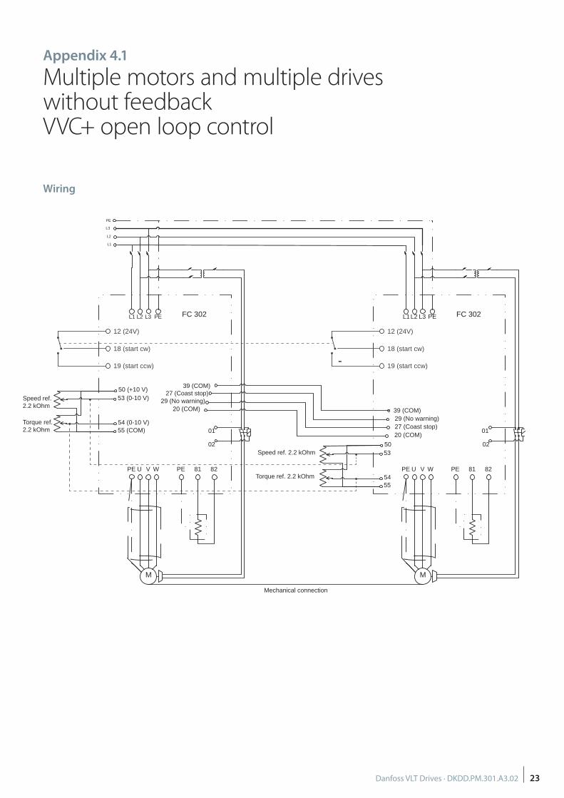
Appendix 4.1
Multiple motors and multiple drives without feedback VVC+ open loop control
Wiring
Speed ref. 2.2 kOhm
Torque ref.2.2 kOhm
Speed ref. 2.2 kOhm
Torque ref. 2.2 kOhm
50 (+10 V)53 (0-10 V)
54 (0-10 V)55 (COM)
50 53
54 55
U 82V W 81
02
01
M
PE PE
L1L2 L3 PE
U 82V W 81
02
01
M
PE PE
L1 L2 L3 PE
39 (COM)
29 (No warning)20 (COM)
20 (COM)
39 (COM)
27 (Coast stop)
27 (Coast stop)29 (No warning)
L3
L2
L1
PE
FC 302FC 302
Mechanical connection
12 (24V)
18 (start cw)
19 (start ccw)
12 (24V)
18 (start cw)
19 (start ccw)

24 Danfoss VLT Drives · DKDD.PM.301.A3.02
Parameter set-up – Multiple motors and multiple drives without feedbackVVC+ open loop control
Par. ID Description Set-up Comment (* = factory settings)
1-00 Confi guration Mode Speed open loop *
1-01 Motor Control Principle VVC+ * (include V/A comp. and slip comp.)
1-03 Torque Characteristics Constant torque *
1-04 Overload Mode High Torque * (150-160% over current available)
1-06 Clockwise Direction Normal * (avoid using this parameter).
1-10 Motor Construction Asynchron * (no PM motor considered here)
1-201-26
Motor Data inserted Motor size = Drive size (150-160% over current available)
1-29 Automatic Motor Adaptation Use complete AMA For larger drive use reduced AMA
1-301-37
Advanced motor data is calculated based on motor data
R1 = stator restistanceXh = main impedance.
R1 should also include cable resistanceXh determine magnetizing current.
1-39 Motor Poles Automatic calculated Calculated based on par. 1-23 and 1-25.Never use synchron speed for par. 1-25.
1-501-52
Magnetizing current at low speed * Use factory settings.
1-601-61
Low Speed and High Speed Compensation (V/A comp.)
* Use factory Settings.
1-62 Slip Compensation - 100%The higher the motor slip is, the better is the natural load sharing. – 100% for large motors with low slip is normally enough; otherwise increase neg. %.
1-64 Resonance Dampening 100% = Normal damping.Resonance damping is based on motor slip. Par.1-23 and par. 1-25. Unstable operation: increase or reduce parameter
1-71 Start Delay 0.1 – 1.5 second. Time needed to magnetize the motor
1-72 Start Function VVC+/fl ux clockwiseVVC+ can ramp up, but not provide motor torque before magnetized.
1-74 Start Speed Use slip in RPMAfter start delay time can the motor provide 100 % nominal torque.
1-80 Function at Stop Coast *
1-81 Min. Speed for Function at Stop 2-3 RPM
1-90 Motor Thermal Protection ETR warning 1 ETR does not require external sensors.
2-10 Brake Function Resistor Brake.Most application require a brake resistor. Large resistors can be water cooled.
2-11 Brake resistor Use factory size. Give 160% generatoric torque
2-12 Brake power limit Use brake information. Average value for the resistor.
2-13 Brake Power Monitoring. Warning. Use as indication for overheating.
2-15 Brake check Warning. Indication for brake failure.
2-18 Brake Check Condition After Coast Situation Additional brake check.
2-20 Release Brake Current Use magnetizing current for the motorWhen the actual current is above the set current within the start delay time, then mechanical brake relay change state.
2-21 Activate Brake Speed Set RPM for closingDetermine physical closing time for the brake. Determine the ramp down time.Calculate the set RPM for closing the brake at 0 RPM.
2-23 Activate Brake Delay 0.1 – 0.5 secondActivate a holding torque, after the brake has closed. Taking care of time delay for worn brake lining.
3-40 Ramp 1 Type Linear* Other ramp types might be better, but can extend actual time.
3-41 Ramp 1. Ramp up time As neededRamp time = time from 0 RPM to synchronous speed. Too short time may activate current /torque warning.
3-42 Ramp 1. Ramp down time As neededRamp time = time from synchronous speed to 0 RPM. Too short time may activate current /torque warning.
4-10 Motor Speed Direction Both directions Winch normally need both directions
4-11 Motor speed Low Limit 0 RPM * Normally no change needed.
4-13 Motor Speed High Limit As needed Lower to max. needed (+ 2 x slip).
4-16 Torque Limit Motor Mode 160% * (suggestion: 15% higher than current limit)

25Danfoss VLT Drives · DKDD.PM.301.A3.02
Par. ID Description Set-up Comment (* = factory settings)
4-17 Torque Limit Generator Mode 160% (suggestion: 15% higher than current limit)
4-18 Current limit Max. % % = Max. current for drive / nominal current for motor.
4-19 Max Output Frequency As needed Slightly higher than parameter 4-13.
4-304-39
Motor tracking error N.B. Do not work for open loop application.
5-11 Terminal 19 Digital Input Start reversingDigital input normally provided by joystick with only one direction signal.
5-40 Function Relay Mechanical brake ctrl.Relay 1 is normally used for this function. Take care of contact burning.
5-41 On Delay, Relay 0.0 – 1.4 secondIf the magnetizing of the motor is longer than the opening of the brake.
5-42 Off Delay, Relay 0.0 second * Normally not used.
6-00 Live Zero Timeout Time 1 second Use where 4-20 mA signal is present.
6-01 Live Zero Timeout Function Stop and trip. Function if reference is lost.
6-15Terminal 53 High ref/(feedback) Value
As needed Reference for 20 mA or 10 Volt.
N.B. Set control card switch for I or V Current or voltage input See settings in parameter 16-61.
7-007-57
PID controller for closed loop regulation.
Not used for VVC+ open loop
14-00 Switching pattern SFAVM* Normally best choice regarding performance and acous-tic noise.
14-01 Switching Frequency* Switching frequency higher than factory settings might decrease thermal performance for the drive.
14-03 Overmodulation * give higher voltage for VVC+ in over synchronous range.
14-10 Mains Failure Controlled ramp down This setting is best choice; but might not work for VVC+.
14-11 Mains Voltage at Mains Fault. As needed Set to 10% below min. mains level.
14-12 Function at Mains Imbalance Warning.Factory setting is trip. A generator supply might activate this trip too often.
14-24 Trip Delay at Current Limit As neededRunning too long in current limit indicate something is overloaded.
14-25 Trip Delay at Torque Limit As neededRunning too long in torque limit indicate something is overloaded.
14-26 Trip Delay at Inverter Fault 0 second Too high voltage = brake faulty.
14-50 RFI Filter Off Factory setting is ON. For IT grids use OFF. For TN grids use ON.
14-90 Fault Level Off * Should not be used ; but fault condition can be changed.
Parameter set-up – Multiple motors and multiple drives without feedbackVVC+ open loop control

26 Danfoss VLT Drives · DKDD.PM.301.A3.02
Appendix 4.2
Multiple motors and multiple drives without feedbackFlux vector open loop control
Wiring
Speed ref. 2.2 kOhm
Torque ref.2.2 kOhm
Speed ref. 2.2 kOhm
Torque ref. 2.2 kOhm
50 (+10 V)53 (0-10 V)
54 (0-10 V)55 (COM)
50 53
54 55
U 82V W 81
02
01
M
PE PE
L1L2 L3 PE
U 82V W 81
02
01
M
PE PE
L1 L2 L3 PE
39 (COM)
29 (No warning)20 (COM)
20 (COM)
39 (COM)
27 (Coast stop)
27 (Coast stop)29 (No warning)
L3
L2
L1
PE
FC 302FC 302
Mechanical connection
12 (24V)
18 (start cw)
19 (start ccw)
12 (24V)
18 (start cw)
19 (start ccw)

27Danfoss VLT Drives · DKDD.PM.301.A3.02
Parameter set-up – Multiple motors and multiple drives without feedbackFlux vector open loop control
Par. ID Description Set-up Comment (* = factory settings)
1-00 Confi guration Mode Speed open loop *
1-01 Motor Control Principle Flux sensorless *
1-03 Torque Characteristics Constant torque *
1-04 Overload Mode High Torque * (150-160% over current available)
1-06 Clockwise Direction Normal * (avoid using this parameter).
1-10 Motor Construction Asynchron * (no PM motor considered here)
1-201-26
Motor Data inserted Motor size = Drive size (150-160% over current available)
1-29 Automatic Motor Adaptation Use complete AMA For larger Drive use reduced AMA
1-301-37
Advanced motor data is calculated based on motor data
R1 = stator resistanceXh = main impedance.
R1 should also include cable resistanceXh determine magnetizing current.
1-39 Motor Poles Automatic calculated Calculated based on par. 1-23 and 1-25.Never use synchron speed for par. 1-25.
1-53 Model Shift Frequency * Use factory settings, or about 15% of nominal frequency.
1-54Voltage reduction in Field- weak-ening
0 Volt* Use factory Settings. Can be increased if voltage is missing in over synchronous range.
1-62 Slip Compensation - 100%The higher the motor slip is, the better is the natural load sharing. – 100% for large motors with low slip is normally enough; otherwise increase neg. %.
1-64 Resonance Dampening 100% = Normal damping.Resonance damping is based on motor slip. Par.1-23 and par. 1-25. Unstable operation: increase or reduce parameter
1-66 Min. Current at Low Speed 100%* 100% = low current is = nominal current. Change if needed.
1-67 Load Type Active Load Enhance the performance at low RPM.
1-71 Start Delay 0.1 – 0.2 second.Time to indicate that current is present for the motor and above parameter 2-20
1-72 Start Function VVC+/fl ux clockwise Will calculate right current for output frequency.
1-74 Start Speed Use slip in RPM Can provide 100 % torque by start
1-80 Function at Stop Coast *
1-81 Min. Speed for Function at Stop 2-3 RPM
1-90 Motor Thermal Protection ETR warning 1 ETR does not require external sensors.
2-10 Brake Function Resistor Brake.Most application requires a brake resistor. Large resistors can be water cooled.
2-11 Brake resistor Use factory size. Give 160% generatoric torque
2-12 Brake power limit Use brake information. Average value for the resistor.
2-13 Brake Power Monitoring. Warning. Use as indication for overheating.
2-15 Brake check Warning. Indication for brake failure.
2-18 Brake Check Condition After Coast Situation Additional brake check.
2-20 Release Brake Current Use magnetizing current for the motorWhen the actual current is above the set current within the start delay time, then mechanical brake relay change state.
2-21 Activate Brake Speed Set RPM for closingDetermine physical closing time for the brake. Determine the ramp down time.Calculate the set RPM for closing the brake at 0 RPM.
2-23 Activate Brake Delay 0.1 – 0.5 secondActivate a holding torque, after the brake has closed. Taking care of time delay for worn brake lining.
3-40 Ramp 1 Type Linear* Other ramp types might be better, but can extend actual time.
3-41 Ramp 1. Ramp up time As neededRamp time = time from 0 RPM to synchronous speed. Too short time may activate current /torque warning.
3-42 Ramp 1. Ramp down time As neededRamp time = time from synchronous speed to 0 RPM. Too short time may activate current /torque warning.
4-10 Motor Speed Direction Both directions Winch normally need both directions
4-11 Motor speed Low Limit 0 RPM * Normally no change needed.
4-13 Motor Speed High Limit As needed Lower to max. needed (+ 2 x slip).
4-16 Torque Limit Motor Mode 160% * (suggestion: 15% higher than current limit)
4-17 Torque Limit Generator Mode 160% (suggestion: 15% higher than current limit)
4-18 Current limit Max. % % = Max. current for drive / nominal current for motor.

28 Danfoss VLT Drives · DKDD.PM.301.A3.02
Par. ID Description Set-up Comment (* = factory settings)
4-19 Max Output Frequency As needed Slightly higher than parameter 4-13.
5-11 Terminal 19 Digital Input Start reversingDigital input normally provided by joystick with only one direction signal.
5-40 Function Relay Mechanical brake ctrl.Relay 1 is normally used for this function. Take care of contact burning.
5-41 On Delay, Relay 0.0 – 1.0 secondAdjust the brake to be open, when the drive start to ramp up.
5-42 Off Delay, Relay 0.0 second * Normally not used.
6-00 Live Zero Timeout Time 1 second Use where 4-20 mA signal is present.
6-01 Live Zero Timeout Function Stop and trip. Function if reference is lost.
6-15Terminal 53 High ref/(feedback) Value
As needed Reference for 20 mA or 10 Volt.
N.B. Set control card switch for I or V Current or voltage input See settings in parameter 16-61.
7-02 Speed PID Proportional Gain 0.015* Should be adjusted. Normally is a higher gain necessary; but take care of instability.
7-03 Speed PID Integral Time 200ms* factory setting is normally O.K. ; but could be reduced for better dynamic operation. Take care of instability.
7-04 Speed PID Diff erentiation Time Off * Normally not used. If set, take care of instability above1 ms.
14-00 Switching pattern SFAVM* Normally best choice regarding performance and acous-tic noise.
14-01 Switching Frequency* Switching frequency higher than factory settings might decrease thermal performance for the drive.
14-10 Mains Failure Ctrl. ramp down This setting is best choice.
14-11 Mains Voltage at Mains Fault. As needed Set to 10% below min. mains level.
14-12 Function at Mains Imbalance Warning.Factory setting is trip. A generator supply might activate this trip too often.
14-24 Trip Delay at Current Limit As neededRunning too long in current limit indicate something is overloaded.
14-25 Trip Delay at Torque Limit As neededRunning too long in torque limit indicate something is overloaded.
14-26 Trip Delay at Inverter Fault 0 second Too high voltage = brake faulty.
14-50 RFI Filter Off Factory setting is ON. For IT grids use OFF. For TN grids use ON
14-90 Fault Level Off * Should not be used ; but fault condition can be changed.
Parameter set-up – Multiple motors and multiple drives without feedbackFlux vector open loop control

29
Appendix 5.1
Multiple motors and multiple drives with feedback (2)Flux vector closed loop controlSpeed droop load sharing concept
WiringThe drawing shows the setup of two frequency converters, each driving a motor that are mechanically coupled on the same
shaft, “Common shaft motors”, either directly, or through a gear box.
Speed ref.2.2kOhm
Torque ref.2.2 kOhm
50 (+10 V)53 (0-10 V)
54 (0-10 V)55 (COM)
50 (+10 V)53 (0-10 V)
54 (0-10 V)55 (COM)
U 82V W 81
02
01
M
PE PE
L1L2 L3 PE
+GNDA+A-B+B-
U 82V W 81
02
01
M
PE PE
L1
12
18
19
12
18
19L2 L3 PE
+GNDA+A-B+B-
L3L2L1
PE
FC 302Master
FC 302Master
Mechanical connection
MCB 102MCB 102

30
Par. ID DescriptionMaster Drive 1Master Drive 2etc.
Comment (* = factory settings)
1-00 Confi guration Mode Speed closed loopAlternatively: Use speed open loop if there is no feedback. In that case ignore parameters 1-01; 1-02 and 17-XX
1-01 Motor Control Principle Flux w/ motor feedback
1-02 Flux Motor Feedback Source MCB 102 TTL 5V encoder used for MCB 102
1-03 Torque Characteristics Constant Power Work sonly for fl ux closed loop.
1-04 Overload Mode High Torque * (150-160% over current available)
1-06 Clockwise Direction Normal * (avoid using this parameter).
1-10 Motor Construction Asynchron * (no PM motor considered here)
1-201-26
Motor Data inserted Motor size = Drive size (150-160% over current available)
1-29 Automatic Motor Adaptation Use complete AMA For larger Drive use reduced AMA
1-301-37
Advanced motor data is calculated based on motor data
R1 = stator resistanceXh = main impedance.
R1 should also include cable resistanceXh determine magnetizing current.
1-39 Motor Poles Automatic calculated Calculated based on par. 1-23 and 1-25.Never use synchron speed for par. 1-25.
1-53 Model Shift Frequency. * Use factory setting. Otherwise use 15% of nominal motor frequency.
1-54Voltage reduction in Fieldweakening.
0V * Use factory setting. In case of warning 62 try to reduce the voltage.
1-62 Slip compensation -100%Only visible in software 6.84 and later for closed loop. Higher - settings give better load sharing, but less dynamic speed accuracy.
1-72 Start Function Hoist Mech. Brake Relay
1-80 Function at Stop Coast *
1-81Min. Speed for Function at Stop
1 RPM
1-90 Motor Thermal Protection ETR warning 1 ETR does not require external sensors.
2-10 Brake Function Resistor Brake.Most application requires a brake resistor. Large resistors can be water cooled.
2-11 Brake resistor Use factory size. Give 160% generatoric torque
2-12 Brake power limit Use brake information. Average value for the resistor.
2-13 Brake Power Monitoring. Warning. Use as indication for overheating.
2-15 Brake check Warning. Indication for brake failure.
2-18 Brake Check Condition After Coast Situation Additional brake check.
2-21 Activate Brake Speed Set RPM for closingDetermine physical closing time for the brake. Determine the ramp down time.Calculate the set RPM for closing the brake at 0 RPM.
2-23 Activate Brake Delay 0.1 – 0.5 secondActivate a holding torque, after the brake has closed. Taking care of time delay for worn brake lining.
2-24 Stop Delay 0 second. * delay time for closing the brake relay.
2-25 Brake Release Time 0.2 second.* Set as needed. Time for the brake to open. Time for increased proportional gain boost.
2-26 Torque Ref. 70% Set as needed. Torque applied against closed brake before brake release.
2-27 Torque Ramp Time 0.2 second * Ramp time for parameter 2-26.
2-28 Gain boost Factor 2.00Set as needed. Increased proportional gain during time for parameter 2-25.
3-00 Reference Range Min. - +Max.Master: Speed reference.Follower: Torque reference.
3-02 Minimum reference As neededMaster: Set min. speed ref.Follower: -(nominal motor torque x settings in par. 4-17).
3-03 Maximum Reference As neededMaster: Set max. speed ref.Follower: nominal motor torque x settings in par. 4-16.
3-40 Ramp 1 Type Linear * Other ramp types might be better, but can extend actual time.
3-41 Ramp 1. Ramp up time As neededRamp time = time from 0 RPM to synchronous speed. Too short time may activate current /torque warning.
Parameter set-up – Multiple motors and multiple drives with feedback (2)Flux vector closed loop control

31
Par. ID DescriptionMaster Drive 1Master Drive 2etc.
Comment (* = factory settings)
3-42 Ramp 1. Ramp down time As neededRamp time = time from synchronous speed to 0 RPM. Too short time may activate current /torque warning.
4-10 Motor Speed Direction Both directions Winch normally need both directions
4-11 Motor speed Low Limit 0 RPM * Normally no change needed.
4-13 Motor Speed High Limit As needed Lower to max. needed (+ 2 x slip).
4-16 Torque Limit Motor Mode 160%* (suggestion: 5% higher than current limit). Goes down with fi eld weakening curve, when parameter 1-03 is set for constant power.
4-17 Torque Limit Generator Mode 160%(suggestion: 5% higher than current limit). Goes down with fi eld weakening curve, when parameter 1-03 is set for constant power.
4-18 Current limit Max. % % = Max. current for drive / nominal current for motor.
4-19 Max Output Frequency As needed Slightly higher than parameter 4-13.
4-20 Torque Limit Factor Source Analog in 54 Can be used to adjust parameter 4-16 and 4-17 by remote potentiometer.
4-30Motor Feedback Loss function
Warning Suggestion is Warning.
4-31 Motor Feedback Speed Error 300 RPM * This window is motor dependent.
4-32. Motor feedback Loss Timeout 1 second Factory setting of 0.05 second might be too fast.
4-34 Tracking Error Function Warning.
4-35 Tracking Error 100 RPM Factory setting of 10 RPM is too small window.
4-36 Tracking Error Timeout 1 second *
4-37 Tracking Error Ramping 100 RPM * Might be increased to 200 RPM if too sensitive.
4-38Tracking Error Ramping Timeout.
5 second * Could be decreased to about 1 second for a faster detection.
5-02 Terminal 29 Mode Running/ no warning When digital terminal 29 is used as digital output
5-11 Terminal 19 Digital Input Start reversing Digital input normally provided by joystick with only one direction signal.
5-12 Terminal 27 Digital Input Stop inverse
5-40 Function Relay Mechanical brake ctrl. Relay 1 is normally used for this function. Take care of contact burning
5-41 On Delay, Relay 0.01 second * Use parameter 2-25 if needed.
5-42 Off Delay, Relay 0.01 second * Normally not used.
6-00 Live Zero Timeout Time 1 second Use where 4-20 mA signal is present.
6-01 Live Zero Timeout Function As needed Function if reference is lost.
6-15Terminal 53 High ref/(feedback) Value
Reference for 20 mA or 10 Volt.
6-22 Terminal 54 Low Current Use 4 mA because super-vision of signal is possible.
6-23 Terminal 54 High Current *
6-24Terminal 54 Low Ref/Feedb. Value
- (Nominal motor torque x settings in par. 4-17) = Param. 3-03 with minus sign.
6-25Terminal 54 High Ref/Feedb. value
Nominal motor torque x settings in par.4-16 = Par 3-03
N.B.Set control card switch for I or V
Current or voltage input See settings in parameter 16-61.
7-00 Speed PID Feedback Source MCB 102 option. * Use 5 V encoder with MCB 102, especially with long cable lengths.
7-02 Speed PID Proportional Gain 0.015 * Master: can be increased. Take care of instability.
7-03 Speed PID integral Time 200 ms * Master: can be decreased for a faster response. Take care of instability.
7-04Speed PID Diff erentiation Time
1 ms Master: Use max. 1- 2 ms for faster response.
7-06Speed PID Lowpass Filter Time
5 ms Adjust to pulses per revolution of encoder. Higher pulses = lower ms.
14-00 Switching pattern SFAVM * Normally best choice regarding performance and acoustic noise.
14-01 Switching Frequency* Switching frequency higher than factory settings might decrease thermal performance for the drive.
14-10 Mains Failure Ctrl. ramp down
14-11 Mains Voltage at Mains Fault. As needed Set to 10% below min. mains level.
Parameter set-up – Multiple motors and multiple drives with feedback (2)Flux vector closed loop control

32
Par. ID DescriptionMaster Drive 1Master Drive 2etc.
Comment (* = factory settings)
14-12 Function at Mains Imbalance Warning.Factory setting is trip. A generator supply might activate this trip too often.
14-24 Trip Delay at Current Limit As neededRunning too long in current limit indicate something is overloaded. (Suggestion: 1 second).
14-25 Trip Delay at Torque Limit As neededRunning too long in torque limit indicate something is overloaded. (Suggestion: 1 second).
14-26 Trip Delay at Inverter Fault 0 second Too high voltage = brake faulty.
14-35 Stall Protection Enable *
14-50 RFI Filter Off Factory setting is ON. For IT grids use OFF. For TN grids use ON.
14-90 Fault Level Off * Should not be used ; but fault condition can be changed.
17-10 Signal Type RS 422 (5 V TTL). * Factory setting for most used encoder.
17-11 Resolution (PPR) 1024 * Factory settings for most popular PPR. Change if needed.
17-60 Feedback direction Counter Clockwise* If over current or tracking error is present at start, then encoder direction most likely is wrong, change settings.
17-61 Feedback Signal Monitoring Warning
Parameter set-up – Multiple motors and multiple drives with feedback (2)Flux vector closed loop control

33
Notes

34

35Danfoss VLT Drives · DKDD.PM.301.A3.02

Danfoss products are everywhere on the ship– improving efficiency, safety and reliability
Working in the challenging world of the marine industry, you
demand a supplier who contributes to improving effi ciency,
safety and reliability while reducing total cost of ownership.
Danfoss is a single supplier who delivers on all these criteria
– and more. For over 30 years we have been building and
consolidating successful relationships with ship owner-
operators, shipyards, system integrators, OEMs, naval design
engineers and architects to make the marine industry safer
and more effi cient. Represented in all major marine hubs
with full marine certifi cation and global service, Danfoss is
committed to creating a sustainable, competitive future for
the marine industry.
Thrusters VLT® and VACON® drives
Pressure & temperature
sensors and controls
Firefi ghting systems
Hydraulic valves and motors
Engine room VLT® and VACON® drives
Pressure & temperature
sensors and controls
IXA emission sensors
Fluid controls
Firefi ghting systems
Hydraulic pumps, valves and motors
Cargo deckFirefi ghting systems
VLT® and VACON® drives
Pressure & temperature
sensors and controls
Hydraulic valves and motors
Winches VLT® and VACON® drives
Hydraulic valves, motors and
control systems
Utilities High pressure pumps
VLT® and VACON® drives
Pressure & temperature
sensors and controls
Fluid controls
Refrigeration controls
Firefi ghting systems
For further information please visit www.marine.danfoss.com
Accommodation Control valves for
air-conditioning
Firefi ghting systems
VLT® and VACON® drives
Floor-heating systems
DKDD.PM.301.A3.02 © Copyright Danfoss Drives | 2015-11
Danfoss VLT Drives, Ulsnaes 1, DK-6300 Graasten, Denmark, Tel. +45 74 88 22 22, Fax +45 74 65 25 80, www.danfoss.com/drives, E-mail: [email protected]