vlt® product catalogue · modbus rtu optional: lonworks (mca 108) bacnet (mca 109) devicenet (mca...
TRANSCRIPT

MAKING MODERN LIVING POSSIBLE
VLT® Product CatalogueDanfoss Drives

2
The leading provider of Drives
Two thousand employees headed from Graasten in Denmark develop, manu facture, sell and service elec-tronic motor controls in more than one hundred countries.
Manufacturing takes place in USA – Especially the high power products –and in Asia, but the major produc-tion takes place in the plants in Graasten, Denmark, where half of the staff are employed. Danfoss Bauer geared motors are manufactured in Esslingen, Germany.
The success of Danfoss is due to the strong combination of technology and application knowledge through-out the world combined with a highly sophisticated set-up of product development, supply chain, logistics and on-site presence anywhere on the globe.
Our customers are closely involved during every stage of design and development, specifying their needs in terms of features and user inter-face. Danfoss Drives dedicates itself to every step in every process until the customer has the drive in hand.
The developers at Danfoss Drives have fully adopted modular principles in development as well as design, pro-duction and confi guration.
Each function is developed in parallel on dedicated technology platforms and interfaces between the elements are carefully defi ned. This allows development to take place for each element in parallel, reducing time to market and ensuring that customers always enjoy the benefi ts of recently developed features.
This unique modular concept is also the basis for a highly automated quality manufacturing process, where Danfoss Drives takes responsibility for every element – starting with the essential semi conductor power modules. Power Modules are pro-duced in Danfoss Silicon Power in Schleswig, Germany. High quality standards and effi cient manufactur-ing facilities makes Danfoss Silicon Power modules in great demand within industries that provide highly automated power-applications like the automotive sector.
When it comes to quality, delivery and cooperation, Danfoss makes high demands on their suppliers – both from inside and outside of the group.
Due to an unsurpassed level of automation Danfoss can produce a customer confi gured drive from 1.6 million possible confi gurations in a manu facturing time of two hours. The unique string type code that fully defi nes the drive can easily be obtained throughout the world by use of the internet; it determines the confi guration of all elements of the drive, both electronics and hardware.
Once this unique confi guration is passed to the production depart-ments the manufacturing process can begin. Testing is carried out at all stages of the process and begins with optical checks of the PCBs to ensure that components are inserted correctly. Once the PCBs are fully assembled they all must pass an automatic in-circuit test. After assembly is complete all drives are tested under full load conditions.
During the drives manufacturing cycle the correct manual is being printed and made avaiable for packing. By the use of this process we ensure that not only the correct language but the very latest version of the manual is always produced and shipped with the correct drive. Just in time delivery is a reality.
Once the drive is shipped, one of more than 60 local Danfoss sales companies can ensure that the drive is correctly installed and commis-sioned. Once the equipment is commis sioned, the level of service the customer requires can be defi ned in an agreement with the customer according to his specifi c needs. At every step of the way, from develop-ment of new technologies and features, the mass production of highly customised products, to installation and service, Danfoss Drives has only the customer in mind.

3
Contents
The VLT ® HVAC Drive integrates and communi-cates seamlessly with all HVAC devices, mastered by Building Management Systems or as stand-alone unit.
VLT® AQUA Drive is the perfect match for pumps and blowers in modern water, waste water, district heating and irrigation applications.
The VLT® Automation-Drive represents a single drive concept to control the entire range of opera-tions from standard to servo on any machine or production line.
An extremely compact series of drives prepared for side-by-side mount-ing and developed specifically for the low power market.
The VLT® Micro Drive is a general purpose drive that can control AC motors up to 22 kW. It’s a small drive with maximum strength and reliability.
The VLT® Decentral FCD 300 is a complete frequency converter designed for decentral mounting.
VLT® HVAC Drive Page 4
VLT® AQUA Drive Page 7
VLT® AutomationDrive Page 10
VLT® 2800 Series Page 14
VLT® Micro Drive Page 16
VLT® Decentral FCD 300 Page 18
The VLT® FCM 300 Series is an integrated drive-motor solution which combines a VLT® frequency converter and a high standard quality motor in a single product.
The VLT® Soft Starter MCD 100 provides soft start features for low power applications 1.1 – 11 kW.
The MCD 200 is a com-pact and cost eff ective soft starter range for applications where direct-on-line starting is undesirable.
The MCD 500 is a total motor starter providing all the best in soft starter func tionality. It off ers the most advanced function-ality and protection of motor and application.
Connecting the AHF 005/010 harmonic fi lter in front of a Danfoss frequency converter is an easy and eff ective way to reduce harmonic distortion.
Sine-wave Filters provide a sinusoidal phase-to-phase motor voltage. Sine-wave Filters reduce motor insulation stress and switching acoustic noise from the motor.
dU/dt fi lters reduce the dU/dt values on the motor terminal phase-to-phase voltage – an issue that is important for short motor cables. The phase-to-phase voltage is still pulse shaped.
The Motion Control Tool MCT 10 is the perfect tool to man-age drive parameters in systems and handle all drive-related data.
DriveProTM is an effi cient productivity programme tailored to meet your specifi c needs. All the necessary VLT® Service facilities are at your disposal, which will minimize downtime and increase productivity at your factory.
VLT® DriveMotor FCM 300 Page 20
VLT® Soft Starter MCD 100 Page 22
VLT® Soft Starter MCD 200 Page 24
VLT® Soft Starter MCD 500 Page 26
VLT® Harmonic Filter Page 28
VLT® Sine-Wave Filter Page 30
VLT® dU/dt Filter Page 32
VLT® Motion Control Tool Page 34
VLT® Service – Your way Page 35
VLT® Set-up SoftwareVLT® Motion Control Tools
Release 2.3.1
© Danfoss A/S 2006-09 All trademarks in this material are property of the respective companies. All r
ights rese
rved.

4
VLT® HVAC Drive
The VLT® HVAC Drive series is available in a wide power range designed for all HVAC applica-tions. An advanced drive built on HVAC dedication.
The new VLT® HVAC Drive is the latest series of HVAC drives from Danfoss with built in intelligence.
The VLT® HVAC Drive has a vast number of functions developed to meet the diverse needs of the HVAC business. It is the perfect match for pumps, fans and compressors in modern buildings that are fi tted with increasingly sophisticated solutions.
Features Benefi t
All built in – low investment
• Modular product concept and a wide range of options
• Low initial investment – max. fl exibility, later upgrade possible
• Dedicated HVAC I/O functionality for temperature sensors etc.
• External convertion saved
• Decentral I/O control via serial communication • Reduced wiring costs. and external
controller I/O saved
• Wide range of HVAC protocols for BMS controller connectivity
• Less extra gateway solutions needed
• 4 x auto tuned PID’s • No external PID controller needed
• Smart Logic Controller • Often makes PLC unnessary
• Real Time Clock • Enables daily and weekly settings
• Integrated fan, pump and compressor functionality i.e.
• Saves external control and concersion equipment
• Fire Override Mode, Dry run Detection Constant Torque etc.
• Protect equipment and save energy
Save energy – less operation cost
• Automatic Energy Optimizer function, advanced version
• Saves 5-15% energy
• Advanced energy monitoring • Overview on energy consumption
• Energy saving functions i.e. fl ow compensation, sleepmode etc.
• Saves energy
Unequalled robustness – maximum uptime
• Robust single enclosure • Maintenance free
• Unique cooling concept with no ambient air fl ow over electronics
• Problem free operation in harsh environments
• Max ambient temp. 50˚ C without derating • No external cooling or over size necessary
User friendly – save commisioning and operating cost
• Awarded graphical display, 27 languages • Eff ective commissioning and operation
• USB plug and play connection • Easy to use PC software tools
• Global HVAC support organization • Local service – globally
Built in DC coils and RFI fi lters – no EMC concerns
• Integrated DC link harmonic fi lters • Small power cables. Meets EN 61000-3-12
• Integrated EMC fi lters • Meets EN 55011 Class B, A1 or A2
Product range3 x 380 – 480 V ...................1.1 – 1000 kW3 x 200 – 240 V ....................... 1.1 – 45 kW3 x 525 – 600 V ...................1.1 – 1000 kW3 x 525 – 690 V .................132 – 1200 kW
With 110% over load torque
Available enclosure ratings:IP 00: ...................................110 – 1000 kWIP 20: ......................................... 1.1 – 90 kWIP 21 (NEMA 1): .................1.1 – 1200 kWIP 54 (NEMA 12): .............110 – 1200 kWIP 55 (NEMA 12): .................... 1.1 – 90 kWIP 66 ........................................... 1.1 – 90 kW
Optional coating providing extra protection for aggressive environments.
The VLT® HVAC Drive family

5
Application optionsA wide range of integrated HVAC options can be fi tted in the drive:
General purpose I/O option (MCB 101): 3 digital inputs, 2 digital outputs, 1 analog current output, 2 analog voltage inputs.
Relay option (MCB 105): Adds 3 relay outputs
Analogue I/O option adds (MCB 109): 3 Pt1000/Ni1000 inputs, 3 analog voltage outputs
External 24 VDC supply option (MCB 107):24 VDC external supply can be con-nected to supply, control and option cards.
Battery back-up for Real Time Clock (MCB 109).
Brake chopper option:Connected to an external brake resis-tor, the built in brake chopper limits the load on the intermediate circuit in the case the motor acts as generator. Mains Disconnect Switch as a built in option
Power optionsA wide range of external power op-tions are available for VLT® HVAC Drive in critical networks or applications:
• Advanced harmonic fi lters: For critical demands on harmonic distortion
• dU/dt fi lters: For special demands on motor isolation protection
• Sine wave fi lters (LC fi lters): For noiseless motor
Mains supply (L1, L2, L3)
Supply voltage 200–240 V ±10%
Supply voltage 380–480 V ±10%
Supply voltage 525–600 V ±10%
Supply frequency 50/60 Hz
Displacement Power Factor (cos φ) near unity (> 0.98)
Switching on input supply L1, L2, L3 1–2 times/min.
Output data (U, V, W)
Output voltage 0–100% of supply voltage
Switching on output Unlimited
Ramp times 1–3600 sec.
Open/Closed loop 0–1000 Hz
Digital inputs
Programmable digital inputs 6*
Logic PNP or NPN
Voltage level 0–24 VDC
* 2 can be used as digital outputs
Pulse inputs
Programmable pulse inputs 2*
Voltage level 0–24 VDC (PNP positive logic)
Pulse input accuracy (0.1–110 kHz)
* Utilize some of the digital inputs
Analog input
Analog inputs 2
Modes Voltage or current
Voltage level 0 V to +10 V (scaleable)
Current level 0/4 to 20 mA (scaleable)
Analog output
Programmable analog outputs 1
Current range at analog output 0/4–20 mA
Relay outputs
Programmable relay outputs 2 (240 VAC, 2 A and 400 VAC, 2 A)
Fieldbus communication
Standard built-in:FC Protocol N2 MetasysFLN ApogeeModbus RTU
Optional:LonWorks (MCA 108)BACnet (MCA 109)DeviceNet (MCA 104)Profi bus (MCA 101)
Specifi cations
HVAC PC software tools• MCT 10 Ideal for commissioning and servicing the drive• VLT® Energy Box Comprehensive energy analysis tool, shows the drive payback time• MCT 31 Harmonics calculations tool
6
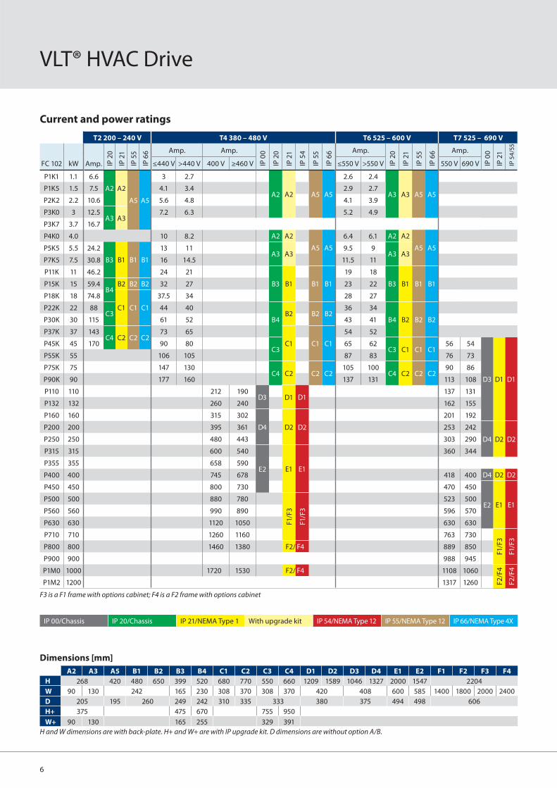
IP 00/Chassis IP 20/Chassis IP 21/NEMA Type 1 With upgrade kit IP 54/NEMA Type 12 IP 55/NEMA Type 12 IP 66/NEMA Type 4X
Current and power ratings
VLT® HVAC Drive
Dimensions [mm]
A2 A3 A5 B1 B2 B3 B4 C1 C2 C3 C4 D1 D2 D3 D4 E1 E2 F1 F2 F3 F4
H 268 420 480 650 399 520 680 770 550 660 1209 1589 1046 1327 2000 1547 2204
W 90 130 242 165 230 308 370 308 370 420 408 600 585 1400 1800 2000 2400
D 205 195 260 249 242 310 335 333 380 375 494 498 606
H+ 375 475 670 755 950
W+ 90 130 165 255 329 391
H and W dimensions are with back-plate. H+ and W+ are with IP upgrade kit. D dimensions are without option A/B.
T2 200 – 240 V T4 380 – 480 V T6 525 – 600 V T7 525 – 690 V
FC 102 kW Amp. IP 2
0
IP 2
1
IP 5
5
IP 6
6 Amp. Amp.
IP 0
0
IP 2
0
IP 2
1
IP 5
4
IP 5
5
IP 6
6 Amp.
IP 2
0
IP 2
1
IP 5
5
IP 6
6 Amp.
IP 0
0
IP 2
1
IP 5
4/5
5
≤440 V >440 V 400 V ≥460 V ≤550 V >550 V 550 V 690 V
P1K1 1.1 6.6
A2 A2
A5 A5
3 2.7
A2 A2 A5 A5
2.6 2.4
A3 A3 A5 A5P1K5 1.5 7.5 4.1 3.4 2.9 2.7
P2K2 2.2 10.6 5.6 4.8 4.1 3.9
P3K0 3 12.5A3 A3
7.2 6.3 5.2 4.9
P3K7 3.7 16.7
P4K0 4.0 10 8.2 A2 A2
A5 A5
6.4 6.1 A2 A2
A5 A5P5K5 5.5 24.2
B3 B1 B1 B1
13 11A3 A3
9.5 9A3 A3
P7K5 7.5 30.8 16 14.5 11.5 11
P11K 11 46.2 24 21
B3 B1 B1 B1
19 18
B3 B1 B1 B1P15K 15 59.4B4
B2 B2 B2 32 27 23 22
P18K 18 74.8
C1 C1 C1
37.5 34 28 27
P22K 22 88C3
44 40
B4B2 B2 B2
36 34
B4 B2 B2 B2P30K 30 115 61 52 43 41
P37K 37 143C4 C2 C2 C2
73 65
C1 C1 C1
54 52
P45K 45 170 90 80C3
65 62C3 C1 C1 C1
56 54
D3 D1 D1
P55K 55 106 105 87 83 76 73
P75K 75 147 130C4 C2 C2 C2
105 100C4 C2 C2 C2
90 86
P90K 90 177 160 137 131 113 108
P110 110 212 190D3 D1 D1
137 131
P132 132 260 240 162 155
P160 160 315 302
D4 D2 D2
201 192
P200 200 395 361 253 242
D4 D2 D2P250 250 480 443 303 290
P315 315 600 540
E2 E1 E1
360 344
P355 355 658 590
P400 400 745 678 418 400 D4 D2 D2
P450 450 800 730 470 450
E2 E1 E1P500 500 880 780
F1/F
3
F1/F
3
523 500
P560 560 990 890 596 570
P630 630 1120 1050 630 630
P710 710 1260 1160 763 730
F1/F
3
F1/F
3
P800 800 1460 1380 F2/ F4 889 850
P900 900 988 945
P1M0 1000 1720 1530 F2/ F4 1108 1060
F2
/F4
F2
/F4
P1M2 1200 1317 1260
F3 is a F1 frame with options cabinet; F4 is a F2 frame with options cabinet

7
VLT® AQUA Drive
Danfoss Drives’ unsurpassed experience in advanced drive technologies for water and wastewater applications makes VLT® AQUA Drive the perfect match for pumps and blowers in modern water, waste water and irrigation systems.
Features Benefi t
Dedicated features
• Dry run detection • Protects the pump
• Flow compensation function • Saves energy
• 2 step ramps (initial ramp) • Protects deep well pumps
• Pipe fi ll mode • Eliminates water hammering
• Built-in motor alternation feature • Duty-stand by operation, cost reduction
• Sleep Mode • Saves energy
• No/low fl ow detection • Protects the pump
• End of pump-curve detection • Protects the pump, leakage detection
• Pump cascade controller • Lower equipment cost
• Master/follower control • High performance pump systems
Energy saving Less operation cost
• VLT® effi ciency (98%) • Saves energy
• Automatic Energy Optimisation (AEO) • Saves 5–15% energy
• Sleep Mode function • Saves energy
Reliable Maximum uptime
• IP 20 – IP 66 enclosures • Outdoor mounting possible
• All power sizes available in IP 54/55 enclosures
• Broad usability
• Password protection • Reliable operation
• Mains disconnect switch • No need for external switch
• Optional, built-in RFI suppression • No need for external modules
• Built-in Smart Logic Controller • Often makes PLC omissible
• One Wire safe stop • Safe operation/less wiring
• Max. ambient temperature up to 50ºC without derating
• Reduced need for cooling
User-friendly Save initial and operation cost
• Award winning control panel (LCP) • Eff ective commissioning and operation
• One drive type for the full power range • Less learning required
• Intuitive user interface • Time saved
• Integrated Real Time Clock • Lower equipment cost
• Modular design • Enables fast installation of options
• Auto tuning of PI-controllers • Time saved
• Payback time indication • Less worries
The perfect match for:• Water supply• Wastewater treatment• District heating• Irrigation
Power range:1 x 200 – 240 V AC: .............. 1.1 – 22 kW1 x 380 – 480 V AC: ............... 7.5 – 37 kW 3 x 200 – 240 V AC: .............0.25 – 45 kW3 x 380 – 480 V AC: ........0.37 – 1000 kW3 x 525 – 690 V AC: ............11 – 1200 kW
The VLT® AQUA Drive family

8
Application optionsA wide range of integrated options can be fi tted in the drive:
General purpose I/O option (MCB 101)3 digital inputs, 2 digital outputs, 1 analog current output, 2 analog voltage inputs
Cascade Controller (MCO 101, 102)Upgrade the built-in cascade control-ler to operate more pumps and for master/follower pump control.
Relay & Analog I/O option (MCB 105, 109)Upgrade to advanced performance and control using the additional in/outputs.
Profi bus (MCA 101), DeviceNet (MCA 104) and EtherNet IP (MCA 121)Fieldbus options.
24 V DC supply option (MCB 107)Back-up option to keep the control system alive during mains loss.
Coated PCB availableFor harsh environments, according to levels in IEC61721–3–3, standard 3C2, optional 3C3.
Power optionsWe off er a wide range of external power options for use together with our drive in critical networks or ap-plications:
• Advanced Harmonic Filters: For applications where reducing harmonic distortion is critical.
• dU/dt fi lters: For providing motor isolation protection.
• Sine fi lters (LC fi lters): For noiseless motor.
Mains supply (L1, L2, L3)
Supply voltage200-240 V ±10%, 380-480 V ±10%, 525-600 V+/-10%, 525-690 V ±10%
Supply frequency 50/60 Hz
Displacement Power Factor (cos φ) near unity (> 0.98)
True power factor (λ) ≥ 0.9
Switching on input supply L1, L2, L3 1–2 times/min.
Output data (U, V,W)
Output voltage 0–100% of supply
Switching on output Unlimited
Ramp times 1–3600 sec.
Closed loop 0–132 Hz
Note: VLT® AQUA Drive can provide 110% current for 1 minute. Higher overload rating is achieved by oversizing the drive.
Digital inputs
Programmable digital inputs 6*
Logic PNP or NPN
Voltage level 0–24 VDC
* Two of the inputs can be used as digital outputs.
Analog inputs
Number of analog inputs 2
Modes Voltage or current
Voltage level -10 to +10 V (scaleable)
Current level 0/4 to 20 mA (scaleable)
Pulse inputs
Programmable pulse inputs 2
Voltage level 0–24 VDC (PNP positive logic)
Pulse input accuracy (0.1–110 kHz)
* Two of the digital inputs can be used for pulse inputs.
Analog output
Programmable analog outputs 1
Current range at analog output 0/4–20 mA
Relay outputs
Programmable relay outputs 2 (240 VAC, 2 A and 400 VAC, 2 A)
Fieldbus Communication
FC Protocol and Modbus RTU built in (DeviceNet, Profi bus and Ethernet IP Optional)
Ambient temperature
Up to max 55° C
AQUA PC software• MCT 10: Ideal for commissioning and
servicing the drive including guided programming of cascade controller, real time clock, smart logic control-ler and preventive maintenance.
• VLT® Energy Box: Comprehensive energy analysis tool, shows the drive payback time.
• MCT 31: Harmonics calculations tool.
Specifi cations
VLT® AQUA Drive

9
IP 00/Chassis IP 20/Chassis IP 21/NEMA Type 1 With upgrade kit IP 54/NEMA Type 12 IP 55/NEMA Type 12 IP 66/NEMA Type 4X
Current and power ratings
Dimensions [mm]
A2 A3 A5 B1 B2 B3 B4 C1 C2 C3 C4 D1 D2 D3 D4 E1 E2 F1 F2 F3 F4
H 268 420 480 650 399 520 680 770 550 660 1209 1589 1046 1327 2000 1547 2204
W 90 130 242 165 230 308 370 308 370 420 408 600 585 1400 1800 2000 2400
D 205 195 260 249 242 310 335 333 380 375 494 498 606
H+ 375 475 670 755 950
W+ 90 130 165 255 329 391
H and W dimensions are with back-plate. H+ and W+ are with IP upgrade kit. D dimensions are without option A/B.
T2 200 – 240 V T4 380 – 480 V T6 525 – 600 V T7 525 – 690 V
FC 202 kW Amp. IP 2
0
IP 2
1
IP 5
5
IP 6
6 Amp. Amp.
IP 0
0
IP 2
0
IP 2
1
IP 5
4
IP 5
5
IP 6
6 Amp.
IP 2
0
IP 2
1
IP 5
5
IP 6
6 Amp.
IP 0
0
IP 2
1
IP 5
4/5
5
≤440 V >440 V 400 V ≥460 V ≤550 V >550 V 550 V 690 V
PK25 0.25 1.8
A2 A2 A5 A5
PK37 0.37 2.4 1.3 1.2
A2 A2 A5 A5
PK55 0.55 3.5 1.8 1.6
PK75 0.75 4.6 2.4 2.1 1.8 1.7
A2 A2 A5 A5
P1K1 1.1 6.6 3 2.7 2.6 2.4
P1K5 1.5 7.5 4.1 3.4 2.9 2.7
P2K2 2.2 10.6 5.6 4.8 4.1 3.9
P3K0 3 12.5A3 A3
7.2 6.3 5.2 4.9
P3K7 3.7 16.7
P4K0 4.0 10 8.2 A2 A2
A5 A5
6.4 6.1 A2 A2
A5 A5P5K5 5.5 24.2
B3 B1 B1 B1
13 11A3 A3
9.5 9A3 A3
P7K5 7.5 30.8 16 14.5 11.5 11
P11K 11 46.2 24 21
B3 B1 B1 B1
19 18
B3 B1 B1 B1
14 13
B2 B2
P15K 15 59.4B4
B2 B2 B2 32 27 23 22 19 18
P18K 18 74.8
C1 C1 C1
37.5 34 28 27 23 22
P22K 22 88C3
44 40
B4B2 B2 B2
36 34
B4 B2 B2 B2
28 27
P30K 30 115 61 52 43 41 36 34
P37K 37 143C4 C2 C2 C2
73 65
C1 C1 C1
54 52 43 41
C2 C2
P45K 45 170 90 80C3
65 62C3 C1 C1 C1
54 52
P55K 55 106 105 87 83 65 62
P75K 75 147 130C4 C2 C2 C2
105 83C4 C2 C2 C2
87 83
P90K 90 212 160 137 131 105 100
P110 110 212 190D3 D1 D1
137 131
D3 D1 D1P132 132 260 240 162 155
P160 160 315 302
D4 D2 D2
201 192
P200 200 395 361 253 242
D4 D2 D2P250 250 480 443 303 290
P315 315 600 540
E2 E1 E1
360 344
P355 355 658 590
P400 400 745 678 418 400 D4 D2 D2
P450 450 800 730 470 450
E2 E1 E1P500 500 880 780
F1/F
3
F1/F
3
523 500
P560 560 990 890 596 570
P630 630 1120 1050 630 630
P710 710 1260 1160 763 730
F1/F
3
F1/F
3
P800 800 1460 1380 F2/ F4 889 850
P900 900 988 945
P1M0 1000 1720 1530 F2/ F4 1108 1060
F2
/F4
F2
/F4
P1M2 1200 1317 1260
F3 is a F1 frame with options cabinet; F4 is a F2 frame with options cabinet

10
VLT® AutomationDrive
The VLT® AutomationDrive is a single drive concept that covers the entire range of application, which is a major benefi t in commissioning, operating and maintaining the equipment.
The modular open-technology platform that VLT® AutomationDrive is built on makes it exceptionally adaptable and programmable. Its confi gurable, user-friendly interface supports local languages and letters.
Pluggable optionsThe drive solution can be adapted to any application due to the fl exible option structure. Numerous options are available and can be mounted and tested from factory or be plugged in later for change-over or upgrade.
Features Benefi t
Reliable Maximum uptime
• Ambient temperature 50° C without derating • Less need for cooling or oversizing
• Available in IP 20, 21, 55 and 66 enclosures • Suitable for harsh and wash down areas
• Resistant to wear and tear • Low lifetime cost
User-friendly Saves commissioning and operating cost
• Plug-and-Play technology • Easy upgrade and change over
• Awarded control panel • User-friendly
• Intuitive VLT® interface • Saves time
• Pluggable cage clamp connectors • Easy connection
• Exchangeable languages • User-friendly
Intelligent
• Intelligent warning systems • Warning before controlled stop
• Smart Logic Control • Reduces need for PLC capacity
• Advanced plug-in features • Easy commissioning
• Safe Stop• Safety cat. 3 (EN 954-1), PL d (ISO 13849-1),
Stop cat. 0 (EN 60204-1)
• STO: Safe Torque Off (IEC 61800-5-2)• SIL 2 (IEC 61508) SIL CL 2 (IEC62061)
• Intelligent heat management • Excess heat eff ectively removed
The VLT® AutomationDrive family
Adapts to the futureThe modular concept of VLT® AutomationDrive makes it highly adaptable – also to future features and options. Modularity off ers the benefi t of buying on a need-to-have basis without losing future possibilities.
Hot pluggable Control PanelThe Local Control Panel (LCP) can be plugged in directly or connected through a cable for remote commis-sioning. The LCP can be disconnected
during operation and replaced with a blind cover. Settings are easily trans- ferred via the LCP from one drive to another or from a PC to a drive with the VLT® Set-up Software MCT 10.
AwardedVLT® AutomationDrive has received the Frost & Sullivan award for innova-tion and the iF Design Award for its user-friendliness.
The perfect solution for:• Industrial automation• High dynamic applications• Safety installations
Power range0.25 – 37 kW ........................ (200 – 240 V)0.37 – 800 kW ...................... (380 – 500 V)0.75 – 75 kW ........................ (525 – 600 V)37 – 1200 MW ..................... (525 – 690 V)

11
OptionsThe following options are available:
Fieldbus options• MCA 101 Profi bus• MCA 104 DeviceNet• MCA 105 CanOpen• MCA 113 Profi bus VLT® 3000
protocol converter• MCA 114 Profi bus VLT® 5000
protocol converter• MCA 121 Ethernet IP
I/O and feedback options• MCA 101 General Purpose I/O• MCB 102 Encoder• MCB 103 Resolver• MCB 105 Relay• MCB 113 Extended Relay Card• MCB 107 24 V input option for
control voltage
Safety options• MCA 131 SafetyBUS p option with
Safe I/O• MCB 108 Safety PLC interface
(DC/DC converter)• MCB 112 ATEX-PTC Thermistor Card
Motion Control Options• MCO 305 Programmable Motion
Controller• MCO 350 Synchronizing Controller• MCO 351 Positioning Controller• MCO 352 Center Winder Controller
Power options• Brake resistors• Sine-Wave Filters• dU/dt Filters• Harmonic Filters (AHF)
Other accessories• IP 21/NEMA 1 Kit
(convert IP 20 to IP 21)• Sub-D9 Connector• Decoupling plate for fi eldbus cables• USB connection cable to PC• Panel Through option
Specifi cations
Mains supply (L1, L2, L3)
Supply voltage
200-240 V ±10%, FC 301: 380-480 V ±10%/FC 302: 380-500 V ±10%, 525-600 V ±10%,525-690 V ±10%
Supply frequency 50/60 Hz
True Power Factor (λ) 0.92 nominal at rated load
Displacement Power Factor (cosф) near unity (>0.98)
Switching on input supply L1, L2, L3 Maximum 2 times/min.
Output data (U, V, W)
Output voltage 0 – 100% of supply
Output frequency
FC 301: 0.2 – 1000 Hz (0.25 – 75 kW)FC 302: 0 – 1000 Hz (0.25–75 kW) 0 – 800 Hz (90 – 1000 kW) 0 – 300 Hz (Flux mode)
Switching on output Unlimited
Ramp times 0.01 – 3600 sec.
Note: 160% current can be provided for 1 minute. Higher overload rating is achieved by oversizing the drive.
Digital inputs
Programmable digital inputs FC 301: 4 (5) / FC 302: 4 (6)
Logic PNP or NPN
Voltage level 0 – 24 V DC
Note: One/two digital inputs can be programmed as digital output for FC 301/FC 302
Analogue inputs
Number of analogue inputs 2
Modes Voltage or current
Voltage levelFC 301: 0 to +10 VFC 302: -10 to +10 V (scaleable)
Current level 0/4 – 20 mA (scaleable)
Pulse/encoder inputs
Programmable pulse/encoder inputs FC 301: 1/FC 302: 2
Voltage level 0 – 24 V DC (PNP positive logic)
Digital output*
Programmable digital/pulse outputs FC 301: 1/FC 302: 2
Voltage level at digital/frequency output 0 – 24 V
Analogue output*
Programmable analogue outputs 1
Current range 0/4 – 20 mA
Relay outputs*
Programmable relay outputs FC 301: 1/FC 302: 2
Cable lengths
Max. motor cable lengths
FC 301: 50 m/FC 302: 150 m (screened/armoured)FC 301: 75 m/FC 302: 300 m (unscreened/unarmoured)
*More analogue and digital inputs/outputs can be added by options

12
VLT® AutomationDrive
IP 00/Chassis IP 20/Chassis IP 21/NEMA Type 1 With upgrade kit IP 54/NEMA Type 12 IP 55/NEMA Type 12 IP 66/NEMA Type 4X
Current and power ratings
T2 200 – 240 V T4/T5 380 – 480/500 V
FC 300
kW Amp.
IP 2
0
IP 2
1
IP 5
5
IP 6
6 Amp. HO Amp. NO
IP 0
0
IP 2
0
IP 2
1
IP 5
4
IP 5
5
IP 6
6
HO NO HO NO ≤440 V >440 V ≤440 V >440 V
PK25 0.25 1.8
A1*
/A2
A2
A5 A5
PK37 0.37 2.4 1.3 1.2 1.3 1.2
A1*
/A2
A5 A5
PK55 0.55 3.5 1.8 1.6 1.8 1.6
PK75 0.75 4.6 2.4 2.1 2.4 2.1
P1K1 1.1 6.6 3 2.7 3 2.7 A2
P1K5 1.5 7.5 4.1 3.4 4.1 3.4
A2P2K2 2.2 10.6 A2 5.6 4.8 5.6 4.8
P3K0 3 12.5A3 A3
7.2 6.3 7.2 6.3
P3K7 3.7 16.7
P4K0 4.0 10 8.2 10 8.2 A2 A2
A5 A5P5K5 5.5 7.5 24.2 30.8B3 B1 B1 B1
13 11 13 11A3 A3
P7K5 7.5 11 30.8 46.2 16 14.5 16 14.5
P11K 11 15 46.2 59.4B4
B2 B2 B2 24 21 32 27B3 B1 B1 B1
P15K 15 18 59.4 74.8
C1 C1 C1
32 27 37.5 34
P18K 18 22 74.8 88C3
37.5 34 44 40
B4B2 B2 B2
P22K 22 30 88 115 44 40 61 52
P30K 30 37 115 143C4 C2 C2 C2
61 52 73 65
C1 C1 C1P37K 37 45 143 170 73 65 90 80C3
P45K 45 55 90 80 106 105
P55K 55 75 106 105 147 130C4 C2 C2 C2
P75K 75 90 147 130 177 160
400 V ≥460 V 400 V ≥460 V
P90K 90 110 177 160 212 190D3 D1 D1
P110 110 132 212 190 260 240
P132 132 160 260 240 315 302
D4 D2 D2P160 160 200 315 302 395 361
P200 200 250 395 361 480 443
P250 250 315 480 443 600 540
E2 E1 E1P315 315 355 600 540 658 590
P355 355 400 658 590 745 678
P400 400 450 695 678 800 730
P450 450 500 800 730 880 780
F1/F
3
F1/F
3P500 500 560 880 780 990 890
P560 560 630 990 890 1120 1050
P630 630 710 1120 1050 1260 1160
P710 710 800 1260 1160 1460 1380
F2/F
4
F2/F
4
P800 800 900 1460 1380 1720 1530
P900 900 1000
P1M0 1000 1200
F3 is a F1 frame with options cabinet; F4 is a F2 frame with options cabinet

13
T6 525 – 600 V T7 525 – 690 V
FC 300
kW Amp. HO Amp. NO
IP2
0
IP21
IP5
5
IP6
6 Amp. HO Amp. NO
IP 0
0
IP21
IP
54
/55
HO NO ≤550 V >550 V ≤550 V >550 V 550 V 690 V 550 V 690 V
PK25 0.25
PK37 0.37
PK55 0.55
PK75 0.75 1.8 1.7
A3 A3 A5 A5
P1K1 1.1 2.6 2.4
P1K5 1.5 2.9 2.7
P2K2 2.2 4.1 3.9
P3K0 3 5.2 4.9
P3K7 3.7
P4K0 4.0 6.4 6.1
A3 A3 A5 A5P5K5 5.5 7.5 9.5 9
P7K5 7.5 11 11.5 11
P11K 11 15 19 18 23 22B3 B1 B1 B1
14 13 19 18
B2 B2P15K 15 18 23 22 28 27 19 18 23 22
P18K 18 22 28 27 36 34
B4B2 B2 B2
23 22 28 27
P22K 22 30 36 34 43 41 28 27 36 34
P30K 30 37 43 41 54 52
C1 C1 C1
36 34 43 41
C2 C2
P37K 37 45 54 52 65 62C3
43 41 54 52
P45K 45 55 65 62 87 83 54 52 65 62
P55K 55 75 87 83 105 100C4 C2 C2 C2
65 62 87 83
P75K 75 90 105 100 137 131 87 83 105 100
P90K 90 110 113 108 137 131
D3 D1 D1P110 110 132 137 131 162 155
P132 132 160 162 155 201 192
P160 160 200 201 192 253 242
D4 D2 D2P200 200 250 253 242 303 290
P250 250 315 303 290 360 344
P315 315 355 360 344 418 400
P355 355 400 395 380 470 450E2 E1 E1
P400 400 450 429 410 523 500
P450 450 500
P500 500 560 523 500 596 570E2 E1 E1
P560 560 630 596 570 630 630
P630 630 710 659 630 763 730
F1/F
3
F1/F
3
P710 710 800 763 630 730 850
P800 800 900 889 730 850 945
P900 900 1000 988 850 945 1060
F2
/F4
F2
/F4
P1M0 1000 1200 1108 945 1060 1260
Dimensions [mm]
A1 A2 A3 A5 B1 B2 B3 B4 C1 C2 C3 C4 D1 D2 D3 D4 E1 E2 F1 F2 F3 F4
H 200 268 420 480 650 399 520 680 770 550 660 1209 1589 1046 1327 2000 1547 2204
W 75 90 130 242 165 230 308 370 308 370 420 408 600 585 1400 1800 2000 2400
D 207 205 195 260 249 242 310 335 333 380 375 494 498 606
H+ 375 475 670 755 950
W+ 90 130 165 255 329 391
H and W dimensions are with back-plate. H+ and W+ are with IP upgrade kit. D dimensions are without option A/B.

14
VLT® 2800 Series
The VLT® 2800 series has been developed for the low power market. The drive is extremely compact and prepared for side-by-side mounting. The concept is modular with a power module and a control module.
The VLT® 2800 series is designed for
stable operation in industrial environ-
ments.
The perfect solution for: • Conveyors, centrifuges, dosing
pumps, compressors• Special applications like cutting
machines with constant speed, and packaging machines with a need for high precision.
Power range1/3 x 200 – 240 V ................0.37 – 3.7 kW 3 x 380 – 480 V ................. 0.55 – 18.5 kW
With 160% overload torque (normal overload)
Features Benefi ts
• Automatic Motor Tuning• Ensure optimal match between drive
and motor• Increasing performance
• PID-controller • Optimum process control
• Interrupt start/stop • High repeatability of positional accuracy
• Dry run detection • No need for specifi c detection equipment
• Fieldbus communication• Allows for control and surveillance of the
drives from a PC or a PLC• Profi bus and DeviceNet are available
Reliable Maximum up-time
• Built-in RFI fi lter• Compliance with the EMC standard
EN 55011 1A
• Enhanced sleep mode• Excellent control for shutting down the
pump at low fl ow
• Max. ambient temperature 45° C without derating
• No external cooling or oversizing necessary
User-friendly Save commissioning and operating cost
• Quick Menu • Easy to use
• Pipe Fill mode • Prevents water hammering
• Fieldbus communication• Allows for control and surveillance of
the drives from a PC or a PLC• Profi bus and DeviceNet are available

15
PC software tools• MCT 10
– Ideal for commissioning and servicing the drive
• MCT 31 – Harmonics calculations tool RFI fi lterThe RFI fi lter ensures that the frequency converter will not disrupt other electrical components that are connected to the mains and might cause operating disruption.
By fi tting an RFI 1B fi lter module between the mains supply and the VLT® 2800, the solution complies with the EMC norm EN 55011-1B.
Specifi cations
Mains supply (L1, L2, L3)
Supply voltage 200-240 V ±10%, 380-480 V ±10%
Supply frequency 50/60 Hz
Displacement Power Factor (cos φ) near unity (> 0.98)
Switching on input supply L1, L2, L3 1–2 times/min.
Output data (U, V, W)
Output voltage 0–100% of supply
Switching on output Unlimited
Ramp times 1–3600 sec.
Closed loop 0–132 Hz
Digital inputs
For start/stop, reset, thermistor, etc. 5
Logic PNP or NPN
Voltage level 0–24 VDC
Digital outputs
No. of digital outputs 1
Analog inputs
No. of analog inputs 2
Voltage level -10 to +10 V (scaleable)
Current level 0/4 to 20 mA (scaleable)
Pulse inputs
No. of pulse inputs 2
Voltage level 0-24 VDC (PNP positive logic)
Pulse input accuracy (0.1–110 kHz)
Analog outputs
Programmable analog outputs 1
Current range at analog output 0/4–20 mA
Relay outputs
No. of relay outputs 1
Fieldbus communication
RS485
Ambient temperature
50˚C
D
B
A C
Height
A B C D
A 200 267.5 267.5 505
a 191 257 257 490
Width
B 75 90 140 200
b 60 70 120 120
Depth
C 168 168 168 244
Power Input current
Mains TypePN,M
[kW]IINV
[A]IL,N
[A]
1 x
22
0-2
40
V
2803 0.37 2.2 5.9
2805 0.55 3.2 8.3
2807 0.75 4.2 10.6
2811 1.1 6.0 14.5
2815 1.5 6.8 15.2
2822* 2.2 9.6 22.0
2840* 3.7 16.0 31.0
3 x
20
0-2
40
V
2803 0.37 2.2 2.9
2805 0.55 3.2 4.0
2807 0.75 4.2 5.1
2811 1.1 6.0 7.0
2815 1.5 6.8 7.6
2822 2.2 9.6 8.8
2840 3.7 16.0 14.7
3 x
38
0-4
80
V
2805 0.55 1.7 1.6
2807 0.75 2.1 1.9
2811 1.1 3.0 2.6
2815 1.5 3.7 3.2
2822 2.2 5.2 4.7
2830 3.0 7.0 6.1
2840 4.0 9.1 8.1
2855 5.5 12 10.6
2875 7.5 16 14.9
2880 11.0 24 24.0
2881 15.0 32 32.0
2882 18.5 37.5 37.5
* Not available with RFI fi lter
Cabinet sizes [mm]

16
VLT® Micro Drive
The VLT® Micro Drive is a general purpose drive that can control AC motors up to 22 kW. It’s a small drive with maximum strength and reliability.
RoHS compliantThe VLT® Micro Drive is manufactured with respect for the environment, and it complies with the RoHS Directive.
The perfect match for:• Industrial appliances• HVAC applications• OEM
Power range:1 phase 200–240 V AC .....0.18–2.2 kW3 phase 200–240 V AC .....0.25–3.7 kW 3 phase 380–480 V AC ......0.37–22 kW
Features Benefi ts
User friendly
• Minimum commissioning • Saves time
• Mount – connect – go! • Minimum eff ort - minimum time
• Copy settings via local control panel • Easy programming of multiple drives
• Intuitive parameter structure • Minimal manual reading
• Complies with VLT® software • Saves commissioning time
• Self-protecting features • Lean operation
• Process PI-controller • No need for external controller
• Automatic Motor Adaptation (AMA) • Exploits motor’s full potential
• 150% motor torque up to 1 minute• Plenty of brake-away and acceleration torque
• Flying start (catch a spinning motor)• Doesn’t trip when started on a spinning (freewheeling) motor
• Electronic Thermal Relay (ETR) • Replaces external motor protection
• Precise stop function • Lean production – more up-time
• Smart Logic Controller • Often makes PLC unnecessary
• Built-in RFI fi lter • Saves cost and space
Energy saving Less operation cost
• Energy effi ciency 98% • Minimises heat loss
• Automatic Energy Optimisation (AEO) • Saves 5-15% energy in HVAC applications
Reliable Maximum uptime
• Earth fault protection • Protects the drive
• Over temperature protection • Protects the motor and drive
• Short circuit protection • Protects the drive
• Optimum heat dissipation • Longer lifetime
• High quality electronics • Low lifetime cost
• High quality capacitors • Tolerates uneven mains supply
• All drives full load tested from factory • High reliability
• Dust resistant • Optimised productivity
• Tight enclosure • Increased lifetime
• RoHS compliant • Protects the environment
• Designed for WEEE • Protects the environment

17
Coated PCB standardFor harsh environments.
Power optionsDanfoss Drives off ers a wide range of external power options for use together with our drives in critical networks or applications:
• Advanced Harmonic Filters: For applications where reducing
harmonic distortion is critical
PC software• MCT 10 – Ideal for commissioning and
servicing the drive including guided programming of cascade controller, real-time clock, smart logic controller and preventive maintenance.
• VLT Energy Box – Comprehensive energy analysis tool, shows the drive payback time.
• MCT 31 – Harmonics calculations tool.
Specifi cations
200 V 400 V
Power [kW]
Current [I-nom.]
1 ph. 3 ph.Current [I-nom.]
3 ph.
0.18 1.2 132F 0001
0.25 1.5 132F 0008
0.37 2.2 132F 0002 132F 0009 1.2 132F 0017
0.75 4.2 132F 0003 132F 0010 2.2 132F 0018
1.5 6.8 132F 0005 132F 0012 3.7 132F 0020
2.2 9.6 132F 0007 132F 0014 5.3 132F 0022
3.0 7.2 132F 0024
3.7 15.2 132F 0016
4.0
Micro drives from 1.5 kW and uphave built in brake chopper
9.0 132F 0026
5.5 12.0 132F 0028
7.5 15.5 132F 0030
11.0 23.0 132F 0058
15.0 31.0 132F 0059
18.5 37.0 132F 0060
22.0 43.0 132F 0061
Ordering numbers
[mm] M1 M2 M3 M4 M5
Height 150 176 239 292 335
Width 70 75 90 125 165
Depth 148 168 194 241 248
Cabinet sizes (mounting fl ange incl.)
+ 6 mm with potentiometer
Mains supply (L1, L2, L3)
Supply voltage1 x 200–240 V ±10%, 3 x 200–240 V ±10%3 x 380–480 V ±10%
Supply frequency 50/60 Hz
Displacement Power Factor (cos φ) near unity (> 0.98)
Switching on input supply L1, L2, L3 1–2 times/min.
Output data (U, V, W)
Output voltage 0–100% of supply voltage
Output frequency 0–200 Hz (VVC+ mode), 0–400 Hz (U/f mode)
Switching on output Unlimited
Ramp times 0.05–3600 sec
Digital inputs
Programmable inputs 5
Logic PNP or NPN
Voltage level 0–24 V
Pulse inputs
Programmable pulse inputs 1*
Voltage level 0–24 V DC (PNP positive logic)
Pulse input frequency 20–5000 Hz
* One of the digital inputs can be used for pulse inputs.
Analog input
Analog inputs 2
Modes 1 current/1 voltage or current
Voltage level 0 – 10 V (scaleable)
Current level 0/4–20 mA (scaleable)
Analog output
Programmable analog outputs 1
Current range at analog output 0/4–20 mA
Relay outputs
Programmable relay outputs 1 (240 VAC, 2 A)
Approvals
CE, C-tick, UL
Fieldbus communication
FC Protocol, Modbus RTU
VLT® Control panel LCP 11 .............................................................................Without potentiometer: 132B0100VLT® Control panel LCP 12 ....................................................................................With potentiometer: 132B0101
M3 M4 M5M2M1

18
VLT® Decentral FCD 300
The perfect solution for: • Material handling in Food &
Beverage and Industry• Installations in wash-down areas• Widely distributed applications
Power range 0.37 – 3.3 kW, 3 x 380 – 480 V EnclosureIP66/Type 4X (indoor)
The VLT® Decentral FCD 300 is a complete frequency converter designed for decentral mount-ing. It can be mounted on the machine or wall close to the motor, or directly on the motor.
The VLT® Decentral FCD 300 comes in very robust enclosure, with a special painting treatment to withstand harsh environments and typical cleaning agents used in wash-down areas. Its design off ers a smooth cleaning-friendly surface.
The decentral design reduces the need for central control panels and eliminates the need for space-con-suming motor control cabinets. The need for long screened motor cables is signifi cantly reduced.
Features Benefi ts
User-friendly Save commissioning and operating cost
• Adapts to any brand of motor and geared motor
• Easy and fl exible installation
• Designed for power and fi eldbus looping • Cable savings
• Visible LEDs • Easy status check
• Set-up and controlled through a remote control panel or fi eldbus communication and dedicated MCT 10 set-up software
• Easy commissioning
Reliable Maximum up-time
• Special surface treatment as protection against aggressive environments
• Easy cleaning; no dirt trap
• Twin part design (installation box and electronic part)
• Easy and fast service
• Integrated lockable service switch available
• Local disconnecting possible
• Full protection is off ered • Protects the motor and drive
Central Vs. Decentral concept Robust cleaning-friendly surface Hot pluggable LCP

19
Specifi cationsMains supply (L1, L2, L3)
Supply voltage 3 x 380/400/415/440/480 V ±10%
Supply frequency 50/60 Hz
Max. imbalance on supply voltage ±2.0% of rated supply voltage
Switching on input supply 2 times/min.
Power Factor (cos φ) 0.9 /1.0 at rated load
Output data (U, V, W)
Output voltage 0–100% of supply
Overload torque 160% for 60 sec.
Switching on output Unlimited
Ramp times 0.02 - 3600 sec.
Output frequency 0.2 - 132 Hz, 1 - 1000 Hz
Digital inputs
Programmable digital inputs 5
Voltage level 0–24 V DC (PNP positive logic)
Analog inputs
Analog inputs 2 (1 voltage, 1 current)
Voltage level/Current level 0– ±10 V DC / 0/4–20 mA (scaleables)
Pulse inputs
Programmable pulse inputs 2 (24 V DC)
Max. frequency 110 kHz (push-pull) / 5 kHz (open collector)
Analog output
Programmable analog output 1
Current range 0/4–20 mA
Digital output
Programmable digital/frequency output 1
Voltage/frequency level 24 V DC/10 kHz (max.)
Relay output
Programmable relay output 1
Max. terminal load 250 V AC, 2 A, 500 VA
Fieldbus communication
FC Protocol, Modbus RTU, Metasys N2 Built-in
Profi bus DP, DeviceNet, AS-interface Optional (integrated)
Externals
Vibration test 1.0 g (IEC 60068)
Max. relative humidity 95 % (IEC 60068-2-3)
Ambient temperature Max. 40˚C (24 hour average max. 35˚C)
Min. ambient temperature in full operation 0˚C
Min. ambient temperature at reduced performance
-10˚C
Approvals CE, UL, C-tick, ATEX*
* Contact Danfoss for details
Plug-and-driveThe bottom section contains main-tenance-free Cage Clamp connectors and looping facilities for power and fi eldbus cables. Once installed, commissioning and upgrading can be performed in no time by plugging in another control lid.
Flexible installationThe FCD 300 series facilitates internal power line and fi eldbus looping. Terminals for 4 mm2 power cables inside the enclosure allows connec-tion of up to 10+ units.
Available options• Service switch• Connector for control panel• M12 connectors for external sensors• Han 10E motor connector• Brake chopper and resistor• 24 V external back up of control and communication• External electromechanical brake
control and supply
VLT® Decentral FCD 303 305 307 311 315 322 330 335*
Output current(3 x 380 – 480 V)
IINV (60s) [A] 1.4 1.8 2.2 3.0 3.7 5.2 7.0 7.6
IMAX (60s) [A] 2.2 2.9 3.5 4.8 5.9 8.3 11.2 11.4
Output power (400 V) SINV [KVA] 1.0 1.2 1.5 2.0 2.6 3.6 4.8 5.3
Typical shaft outputPM,N [kW] 0.37 0.55 0.75 1.1 1.5 2.2 3.0 3.3
PM,N [HP] 0.5 0.75 1.0 1.5 2.0 3.0 4.0 5.0
Mechanical dimensionsH x W x D (mm)
Motor mounting 244 x 192 x 142 300 x 258 x 151
Stand alone 300 x 192 x 145 367 x 258 x 154
* tamb max. 35˚ C
Technical data

20
VLT® DriveMotor FCM 300
The perfect match for:• Air Handling Unit fan wheels• Pumps• Simple conveyors
Power range:0.55 – 7.5 kW, 3 x 380 – 480 V
Enclosure:IP55 (standard)IP65/IP66 (optional)
Motor type:2-pole4-pole
Mounting versions:B03 footB05 fl ange B35 foot + fl angeB14 faceB34 foot + face
Features Benefi ts
User-friendly Save commissioning and operating cost
• Motor and drive perfectly matched to each other
• Saves commissioning time
• No panel space required – the DriveMotor is placed on the machine
• Saves space
• Flexible mounting – foot/fl ange/face/foot-fl ange/foot-face
• Meets customer requirements
• Retrofi t without mechanical changes • Easy service
• Set-up and controlled through a remote control panel or fi eldbus communication and dedicated MCT 10 set-up software
• Easy commissioning
Reliable Maximum up-time
• Robust enclosure • Withstands harsh environments
• No power cable length limitation • Increased fl exibility
• Thermal protection • Total motor-inverter protection
• Straightforward EMC compliance• No problem with electromagnetic
interferences
The VLT® FCM 300 Series is an integrated drive-motor solution which combines a VLT® frequen-cy converter and a high stan-dard quality motor in a single product.
The frequency converter is attached in place of the motor terminal box and it is no higher than the standard terminal box nor wider or longer than the motor.
Incorporated to a high standard quality motor, the VLT® DriveMotor FCM 300 is also available in a multi-tude of variants, individualised to meet customer requirements.
On the motorThe VLT® electronic motor control together with the motor totally eliminates motor cables and thereby minimises EMC problems. Heat from the drive is dissipated together with the motor heat.
All-in-one DriveMotor solution Flexible motor mounting

21
Specifi cationsMains supply (L1, L2, L3)
Supply voltage 3 x 380/400/415/440/460/480V ±10%
Supply frequency 50/60 Hz
Power factor (cos φ) Max. 0.9/1.0 at rated load
Max. imbalance of supply voltage ±2% of rated supply voltage
Switching on supply input Once every 2 minutes
Control Characteristics (frequency converter)
Frequency range 0 – 132 Hz
Overload torque 160% for 60 sec.
Resolution on output frequency 0.1%
System response time 30 msec. ±10 msec.
Speed accuracy±15 RPM (open loop, CT mode, 4-pole motor 150 – 1500 RPM)
Digital inputs
Programmabel digital inputs 4
Voltage level 0 – 24 V DC (PNP positive logic)
Analog inputs
Analog inputs 2 (1 voltage, 1 current)
Voltage/current level 0 – 10 V DC / 0/4 – 20 mA (scaleables)
Pulse input
Programmable pulse input 1 (24 V DC)
Max. frequency 70 kHz (push-pull) / 8 kHz (open collector)
Analog/digital output
Programmable analog/digital output 1
Current/voltage range 0/4 – 20 mA / 24 V DC
Relay output
Programmable relay output 1
Max. terminal load 250 V AC, 2 A, 500 VA
Fieldbus communication
FC Protocol, Modbus RTU Built-in
Profi bus DP Optional (integrated)
Externals
Vibration test 1.0 g (IEC 60068)
Max. relative humidity 95% (IEC 60068-2-3)
Ambient temperature Max. 40˚ C (24 hour average max. 35˚ C)
Min. ambient temperature in full operation 0˚C
Min. ambient temperature at reduced performance
-10˚ C
FCM 305 307 311 315 322 330 340 355 375
Motor output
[HP] 0.75 1.0 1.5 2.0 3.0 4.0 5.0 7.5 10.0
[kW] 0.55 0.75 1.1 1.5 2.2 3.0 4.0 5.5 7.5
Motor torque
2-pole [Nm] 1) 1.8 2.4 3.5 4.8 7.0 9.5 12.6 17.5 24.0
4-pole [Nm] 2) 3.5 4.8 7.0 9.6 14.0 19.1 25.4 35.0 48.0
Frame size
[mm] 80 80 90 90 100 100 112 132 132
Input current [A] 380 V
2-pole 1.5 1.8 2.3 3.4 4.5 5.0 8.0 12.0 15.0
4-pole 1.4 1.7 2.5 3.3 4.7 6.4 8.0 11.0 15.5
Input current [A] 480 V
2-pole 1.2 1.4 1.8 2.7 3.6 4.0 6.3 9.5 11.9
4-pole 1.1 1.3 2.0 2.6 3.7 5.1 6.3 8.7 12.3
1) at 400 V, 3000 RPM, 2) at 400 V, 1500 RPM
Technical Data
Control panelA Local Control Panel is available foroperating, setup and diagnostics. The LCP can be handheld or mounted in a panel front (IP65).
Sleep ModeIn Sleep Mode the motor will stop in a no load situation. When the load returns, the frequency converter will restart the motor.
Also available:
Forced ventilation For constant operation at low speed without torque reduction.
Motor drain holesFor applications where formation of condensate water might occur.
Sensorless Pump Control – OEM version. Off ers precise pressure (head) control without using a pressure transmitter.

22
MCD 100 is a cost eff ective and extremely compact soft starter for AC motors.
A true “fit and forget” soft starter for DIN rail mount MCD 100 provides basic soft start and stop function.
• A robust semiconductor design – selection can be based on motor power which ensures easy
selection.• Can be used for an almost unlimited number of starts per hour without derating.• A universal control voltage (24-480 V AC/ V DC) – simplifi es selection and keeps stock at a minimum.• A “fi t and forget” contactor design – simplifi es installation and reduces required panel space.• Digitally controlled rotary switches – secures precise settings and simplifi es installation.• Ratings for heavy duty as standard – simplifi es installation and reduces the risk of breakdown
Timed voltage ramp• Micro Soft Start Controller for motors up to 11kW• Extremely robust SCR design with heavy ratings as standard• Unlimited number of starts per hour• Contactor style design for easy selection, installation and commissioning
The perfect match for:• Smaller compressors for example
scroll or reciprocating compressors in air-conditioning units.
• Conveyor systems• Pumps
Power range:MCD 100-001 ...................................1,5 kWMCD 100-007 ...................................7,5 kWMCD 100-011 ....................................11 kW
All sizes are rated for line voltage up to
600 V AC.
Features Benefi ts
• Small footprint and compact size • Saves panel space
• Selection can be based on motor power • Easy selection
• Universal control voltage• Simplifi es selection • Keeps stock at a minimum
• “Fit and forget” contactor design• Simplifi es installation • Reduces required panel space
Reliable Maximum up-time
• Robust semiconductor design • Reliable operation
• Almost unlimited number of starts per hour without derating
• Prevents unauthorized changes
• Max. ambient temperature 50˚C without derating
• No external cooling or oversizing necessary
User-friendly Save commissioning and operating cost
• Easy to install and use • Saves times
• Digitally controlled rotary switches• Secures precise settings and simplifi es installation
• Easy DIN rail mounting for sizes up to 30 kW • Saves time and space
Motor torque(Voltage)
100%
“Kick start”200 msec.of max. torque
Initial Torque up to85% of nominal torque
Time0%
Ramp-up time0,5-10 sec.
Ramp-down time0-10 sec.
VLT® Soft Starter MCD 100

23
ModelPower size
(kW)Rated current
(Amps)Dimensions
(mm) H x W x DApprovals
MCD100
1.53 A: 5-5:10(AC 53b)
102x22,5x124
UL, CSA, CE7.515 A: 8-3:100-3000(AC 53a)
110x45x128
1125 A: 6-5:100-480
(AC 53a)110x90x128
Specifi cationsMains supply (L1, L2, L3)
MCD 100 3 x 208 VAC ~ 600 VAC (+10% / -15%)
Supply frequency (at start) 45 Hz – 66 Hz
Control circuit (A1, A2)
MCD 100 24 – 480 VAC/VDC (-15% +10%)
Environmental
Degree of protection MCD 100 IP 20
Operating temperatures -5° C/+40° C (60° C with de-rating)
Pollution Degree Pollution Degree 3
EMC Emission
Equipment class (EMC) Class A
Conducted radio frequency emission
0.15 MHz – 0.5 MHz < 90 dB (μV)
0.5 MHz – 5 MHz < 76 dB (μV)
5 MHz – 30 MHz 80-60 dB (μV)
Radiated radio frequency emission
30 MHz – 230 MHz < 30 dB (μV/m)
230 MHz – 1000 MHz < 37 dB (μV/m)
This product has been designed for Class A equipment. Use of the product in domestic environments may cause radio interference, in wich case the user may be required to employ additional mitigation methods.
EMC Immunity
Electro static discharge 4 kV contact discharge, 8 kV air discharge
Radio-frequency electromagnetic fi eld
0.15 MHz – 1000 MHz 140 dB (μV)
Rated impulse withstand voltage (Fast transients 5/50 ns – Burst)
4 kV line to earth
Rated insulation voltage (Surges 1.2/50 μs – 8/20 μs)
4 kV line to earth, 2 kV line to line
Voltage dip and short time interruption
100 ms (at 40% nominal voltage)
Short Circuit
Rated short-circuit current MCD 100-001 Normal fuses: 25 A gL/gG
SCR I2t rating for semiconductor fuses 72 A2s
Rated short-circuit current MCD 100-007 Normal fuses: 50 A gL/gG
SCR I2t rating for semiconductor fuses 1800 A2s
Rated short-circuit current MCD 100-011 Normal fuses: 80 A gL/gG
SCR I2t rating for semiconductor fuses 6300 A2s
Heat Dissipation
MCD 100-001 Max. 4 watts
MCD 100-007 to MCD 100-011 2 watts/Ampere
Standards Approvals
UL/C-UL UL508
CE IEC 60947-4-2

24
Features Benefi ts
• Small footprint and compact size • Saves panel space
• Built-in bypass
• Minimises installation cost and eliminates power loss
• Reduces heat build up. Savings in compo-nents, cooling, wiring and labor
• Advanced accessoires • Allows enhanced functionality
• Advanced SCR Control Algorithms balances output waveform
• Allowing more starts per hour, accepting higher load
Reliable Maximum up-time
• Essential motor protections (MCD 202) • Reduces overall project investment
• Max. ambient temperature 50° C without derating
• No external cooling or oversizing necessary
User-friendly Save commissioning and operating cost
• Easy to install and use • Saves time
• Easy DIN rail mounting for sizes up to 30 kW • Saves time and space
VLT® Compact Starter MCD 200
The perfect match for:• Pumps• Fans• Compressors• Mixers• Conveyors
Power range:7.5–110 kW
VLT® Compact Starter MCD 200 from Danfoss includes two families of soft starters in the power range from 7.5–110 kW.
The series off er easy DIN rail mount-ing for sizes up to 30 kW, 2-wire or 3-wire start/stop control and excellent starting duty (4 x Ie for 6 seconds).
Heavy starting ratings at 4x Ie for 20 seconds.
Compatible with grounded delta power systems.
Ramp up
Initial current
Current limit
I
Ramp down
U
MCD 201 MCD 202MCD 202 provides enhanced soft start functionality and various motor protection features
Ramp up
Initial torque
Ramp down
U
M3~
M3~

25
Specifi cationsSoft Starter for motors up to 110 kW• Total motor starting solution• Start, stop and protection features• Local programming keypad and display
Optional:• Modules for serial communication.
– DeviceNet– Profibus– Modbus RTU
– USB• Remote operator kit• PC software• Pump application module
Remote operator kitRemote Operator and display with 4–20 mA analogue output propor-tional to motor current (MCD 202)Serial communication: Modbus RTU, AS-i, Profi bus and DeviceNet.PC-based MCD set-up software.
Power range (400 V)
7–30 kW 37–55 kW 75–110 kW
Height [mm] 190 200 225
Width [mm] 96 138 196
Depth [mm] 152 176 TBA
Cabinet sizes
Mains supply (l1, L2, L3)
Supply voltage3 x 200 VAC – 440 VAC or3 x 200 – 575 VAC
Supply frequency 45 – 66 Hz
Control voltage100 – 240 VAC380 – 440 VAC24 VDC/24 VAC
Control inputs
Control inputsStart, StopReset upsh button on the unit
Relay outputs
Relay outputs1 x main contactor1 x programmable* (Trip or Run)
Protections, MCD 201
Phase sequenceSupply faultShorted SCR
Protections, MCD 202
Motor thermistor inputMotor temperature – thermal modelPhase imbalancePhase sequenceExcess start timeSupply faultShorted SCR
LED indications
IndicationsReady/FaultRun
Ambient operating temperature
Ambient temperature -5 to 60˚C (above 40˚C without derating)
Standards approvals
Approvals CE, UL, C-UL, CCC, C-tick

26
VLT® Soft Starter MCD 500
Features Benefi ts
User friendly
• AAC Adaptive Acceleration Control• Automatically adapts to the best starting
and stopping profi le for the application
• Adjustable bus bars allow for both top and bottom entry (360-1600 A, 160-800 kW)
• Space saving, less cable cost and easy retrofi tting
• DC injection braking distributed evenly over three phases
• Less installation cost and less stress on the motor
• Inside Delta (6-wire connection)• Smaller soft starter can be selected
for the application
• Log Menus, 99 Events and Trip log provide information on events, trips and performance
• Eases analysis on the application
• Auto Reset • Less down time
• Jog (slow-speed operation) • Application fl exibility
• Second-order thermal model • Allows motors to be used to their
full potential without damage from overloading
• Internal bypass contactors (21 – 215 A, 7,5 – 110 kW)
• Save space and wiring compared to external bypass
• Very little heat dissipates when running. Eliminates costly external fans, wiring or bypass contactors
• Auto-start/stop clock • Application fl exibility
• Compact size – amongst the smallest in their class
• Saves space in cabinets and other application setups
• 4-line graphical display• Optimum programming approach and
setup for viewing operational status
• Multiple programming setup (Standard Menu, Extended Menu, Quick Set)
• Simplifi es the programming, but still holding to maximum fl exibility
• Multiple (8) languages • Serving the whole world
VLT® Soft Starter MCD 500 is a total motor starting solu-tion. Current transformers measure motor current and provide feedback for control-led motor ramp profi les.
AAC, the Adaptive Acceleration
Control automatically employs the
best starting and stopping profi le for
the application. Adaptive Accelera-
tion Control means, that for each start
and stop, the soft starter compares
and adapts the process to the chosen
profi le fi tting to the application.
The VLT® Soft Starter MCD 500 has a
four line graphical display and a logic
keypad making programming easy.
Advanced setup is possible displaying
operational status.
Three menu systems: Quick Menu,
Application Setup and Main Menu
provide optimum programming
approach.
The perfect solution, also for more
severe applications:
• Pumps
• Conveyors
• Fans
• Mixers
• Compressors
• Centrifuge
• Mill
• Saw
• And many more
Power range
21 – 1600 A, 7,5 – 800 kW
(1,2 MW inside Delta Connection)
Versions for 200 – 690 VAC

27
Specifi cations
Remote operation kit• Start/stop, reset• LED for start, run, trip• Trip codes• Current display• Motor temperature display• 4–20 mA output
DimensionsCurrent rating [A] Weight [kg] Hight [mm] Width [mm] Debth [mm]
21, 37, 43 and 53 4.2
295 150 18368 4.5
84, 89 and 105 4.9
131, 141, 195 and 215 14.9 438 275 250
245 23.9 460 390 279
360, 380 and 428 50.1689 430 302
595, 619, 790 and 927 53.1
1200, 1410 and 1600 120 856 585 364
p
Mains supply (L1, L2, L3)
MCD5-xxxx-T5 200 VAC ~ 525 VAC (± 10%)
MCD5-xxxx-T7380 VAC ~ 690 VAC (± 10%) (earthed star supply system only)
MCD5-xxxx-T7 380 VAC ~ 600 VAC (± 10%) (inside delta connection)
Supply frequency (during start) >45 Hz (50 Hz supply) or >55 Hz (60 Hz supply)
Supply frequency (during run) >48 Hz (50 Hz supply) or >58 Hz (60 Hz supply)
Electronics control voltage 230 VAC (+10%/-15%) or 400 VAC (+10%/-15%)
Control voltage (A4, A5, A6)
CV1 (A5, A6) 24 VAC/VDC (± 20%)
CV2 (A5, A6) 110~120 VAC (+10%/-15%)
CV2 (A4, A6) 220~240 VAC (+10%/-15%)
Mains frequency 50/60 Hz (± 10%)
Rated insulation voltage to earth 600 VAC
Rated impulse withstand voltage 4 kV
Form designationBypassed or continuous, semiconductor motor starter form 1
Short circuit capability
Coordination with semiconductor fuses Type 2
Coordination with HRC fuses Type 1
MCD5-0021B to MCD5-0105B Prospective current 10 kA
MCD5-0131B to MCD5-0245C Prospective current 18 kA
MCD5-0360C to MCD5-0927C Prospective current 85 kA
MCD5-1200C to MCD5-1600C Prospective current 100 kA
Electromagnetic capability (compliant with EU Directive 89/336/EEC)
EMC Emissions (Terminals 13 & 14)IEC 60947-4-2 Class B and Lloyds Marine No. 1 Specifi cation (up to MCD5-215B)
EMC Immunity IEC 60947-4-2
Outputs
Relay Outputs10A @ 250 VAC resistive, 5A @ 250 VAC AC15 pf 0.3
Programmable Outputs
Relay A (13, 14) Normally open
Relay B (21, 22, 24) Changeover
Relay C (33, 34) Normally open
Analog Output (07, 08) 0 – 20 mA or 4 – 20 mA ( selectable)
Maximum load 600 Ω (12 VDC @ 20 mA) (accuracy ± 5%)
24 VDC Output (16, 08) Maximum load 200 mA (accuracy ± 10%)
Environmental
Protection MCD5-0021B ~ MCD5-0105B IP 20 & NEMA, UL Indoor Type 1
Protection MCD5-0131B ~ MCD5-1600C IP 00, UL Indoor Open Type
Operating temperature -10° C to 60° C, above 40° C with derating
Storage temperature - 25° C to + 60° C
Operating Altitude 0 – 1000 m, above 1000 m with derating
Humidity 5% to 95% Relative Humidity
Pollution degree Pollution Degree 3
Heat Dissipation
During start 4.5 watts per ampere
Fully featured Soft Starter for motors up to 800 kW• Total motor starting solution• Advanced start, stop and protection
features• Adaptive Acceleration Control• Inside Delta connection• 4 line graphical display • Multiple programming setup menus
Optional:• Modules for serial communication: – DeviceNet
– Profibus– Modbus RTU
– USB• Remote operator kit• PC software
28
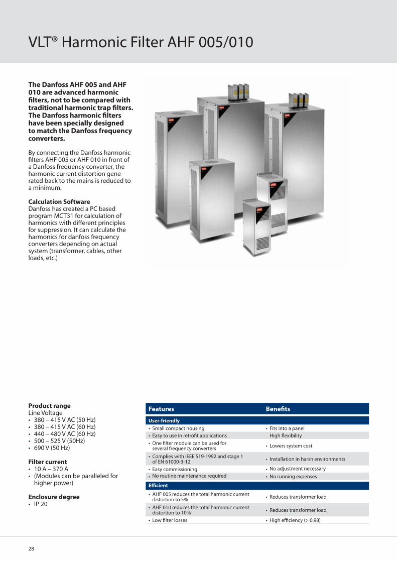
VLT® Harmonic Filter AHF 005/010
Product rangeLine Voltage • 380 – 415 V AC (50 Hz)• 380 – 415 V AC (60 Hz) • 440 – 480 V AC (60 Hz)• 500 – 525 V (50Hz) • 690 V (50 Hz)
Filter current• 10 A – 370 A • (Modules can be paralleled for
higher power)
Enclosure degree• IP 20
Features Benefi ts
User-friendly
• Small compact housing • Fits into a panel
• Easy to use in retrofi t applications High fl exibility
• One fi lter module can be used for several frequency converters
• Lowers system cost
• Complies with IEEE 519-1992 and stage 1 of EN 61000-3-12
• Installation in harsh environments
• Easy commissioning • No adjustment necessary
• No routine maintenance required • No running expenses
Effi cient
• AHF 005 reduces the total harmonic current distortion to 5%
• Reduces transformer load
• AHF 010 reduces the total harmonic current distortion to 10%
• Reduces transformer load
• Low fi lter losses • High effi ciency (> 0.98)
The Danfoss AHF 005 and AHF 010 are advanced harmonic fi lters, not to be compared with traditional harmonic trap fi lters. The Danfoss harmonic fi lters have been specially designed to match the Danfoss frequency converters.
By connecting the Danfoss harmonic fi lters AHF 005 or AHF 010 in front of a Danfoss frequency converter, the harmonic current distortion gene-rated back to the mains is reduced to a minimum.
Calculation SoftwareDanfoss has created a PC based program MCT31 for calculation of harmonics with diff erent principles for suppression. It can calculate the harmonics for danfoss frequency converters depending on actual system (transformer, cables, other loads, etc.)

29
Line voltage ±10%
Frequency +/- 5%
Overload current 160% for 60 s
Effi ciency 0.98
True power factor0.80 @ 50% load0.99 @ 100% load1.0 @ 150% load
Ambient temperature 5˚C – 40˚C without derating
Specifi cations
With AHF 005
With AHF 005
Current and Distortion Spectrum at Full Load
Without fi lter
380 V – 415 V
IAHF,NTypical motor AHF 005 AHF 010
kW HP 50 Hz 60 Hz 50 Hz 60 Hz10 A 4, 5.5 6 175G6600 130B2540 175G6622 130B254119 A 7.5 10, 15 175G6601 130B2460 175G6623 130B247226 A 11 20 175G6602 130B2461 175G6624 130B247335 A 15, 18.5 25, 30 175G6603 130B2462 175G6625 130B247443 A 22 40 175G6604 130B2463 175G6626 130B247572 A 30, 37 50, 60 175G6605 130B2464 175G6627 130B2476
101 A 45, 55 75 175G6606 130B2465 175G6628 130B2477144 A 7.5 100 175G6607 130B2466 175G6629 130B2478180 A 90 125 175G6608 130B2467 175G6630 130B2479217 A 110 150 175G6609 130B2468 175G6631 130B2480289 A 132, 160 200 175G6610 130B2469 175G6632 130B2481324 A 160 250 175G6611 130B2470 175G6633 130B2482370 A 200 300 175G6688 130B2471 175G6691 130B2483434 A 250 2 x 175G6609 2 x 175G6631
506 A 250 350175G6609 + 175G6610
130B2468 + 130B2469
175G6631 + 175G6632
130B2480 + 130B2481
578 A 315 450 2 x 175G6610 2 x 130B2469 2 x 175G6632 2 x 130B2481
613 A 350175G6610 + 175G6611
175G6632 + 175G6633
648 A 355 500 2 x 175G6611 2 x 130B2470 2 x 175G6633 2 x 130B2482
440 V – 480 V
IAHF,NTypical motor
used (HP)AHF 005 AHF 010
19 A 10, 15 175G6612 175G663426 A 20 175G6613 175G663535 A 25, 30 175G6614 175G663643 A 40 175G6615 175G663772 A 50, 60 175G6616 175G6638
101 A 75 175G6617 175G6639144 A 100, 125 175G6618 175G6640180 A 150 175G6619 175G6641217 A 200 175G6620 175G6642289 A 250 175G6621 175G6643324 A 300 175G6689 175G6692370 A 350 175G6690 175G6693506 A 450 175G6620 + 175G6621 175G6642 + 175G6643578 A 500 2 x 175G6621 2 x 175G6643
500 – 525 V
IAHF,NTypical motor
used (kW)AHF 005 AHF 010
10 A 4, 5.5 175G6644 175G665619 A 7.5, 11 175G6645 175G665726 A 15, 18.5 175G6646 175G665835 A 22 175G6647 175G665943 A 30 175G6648 175G666072 A 37, 45 175G6649 175G6661
101 A 55, 75 175G6650 175G6662144 A 90, 110 175G6651 175G6663180 A 132 175G6652 175G6664217 A 160 175G6653 175G6665289 A 200 175G6654 175G6666324 A 250 175G6655 175G6667434 A 315 2 x 175G6653 2 x 175G6665469 A 355 175G6652 + 175G6654 175G6664 + 175G6666578 A 400 2 x 175G6654 2 x 175G6666
690 V
IAHF,NTypical motor
used (kW)AHF 005 AHF 010
43 A 37, 45 130B2328 130B229372 A 55, 75 130B2330 130B2295
101 A 90 130B2331 130B2296144 A 110, 132 130B2333 130B2298180 A 160 130B2334 130B2299217 A 200 130B2335 130B2300289 A 250 130B2331 + 130B2333 130B2301324 A 315 130B2333 + 130B2334 130B2302370 A 400 130B2334 + 130B2335 130B2304
Ordering numbers
Typical without fi lter
With AHF 010
With AHF 010

30
VLT® Power Option Sine-Wave fi lter
The perfect solution for:• Applications with older motors• Aggressive environments• Applications with frequent braking• 690 V applications with general
purpose motors• Motor cable length above 150
metres
Range3 x 200 – 500 V, 2.5 – 1,200 A3 x 525 – 690 V, 13 – 1,320 A
EnclosuresIP00 and IP20 enclosure in the entire power range
Mounting• Side by side mount with the drive
up to 75 A• Filters wall mounted up to
75 A and fl oor mount above
Features Benefi ts
• Supplies the motor with a sinusoidal voltage waveform
• Prevents fl ashover in motor windings
• Eliminates over-voltages and voltage spikes caused by cable refl ections
• Protects the motor insulation againstpremature aging
• Reduces electromagnetic interference by eliminating pulse refl ection caused by current ringing in the motor cable. This allows the use of unshielded motor cables in some applica-tions.
• Trouble-free operation
• Eliminates acoustic noise in motor • Noiseless motor operation
• Reduces high frequent losses in motor • Prolongs service interval of motor
Sine-wave output fi lters are low-pass fi lters that suppress the switching frequency compo-nent from the drive and smooth out the phase-to-phase output voltage of the drive to become sinusoidal. This reduces the motor insulation stress and bearing currents.
By supplying the motor with a sinusoidal voltage waveform, the switching acoustic noise from the motor is also eliminated.
Thermal losses and bearing currentsThe sinusoidal voltage supply to the motor reduces hysteresis thermal losses in the motor. Since the motor insulation lifetime is dependent on the motor temperature, the sine-wave fi lter prolongs the lifetime of the motor.
The sinusoidal motor terminal voltage from the sine-wave fi lter furthermore has the advantage of suppressing any bearing currents in the motor. This reduces the risk of fl ash-over in the motor bearings and thereby also contributes to extended motor lifetime and increased service intervals.
Quality and DesignAll fi lters are designed and tested for operation with the VLT® Automation-Drive FC 302, VLT® AQUA Drive FC 202, and the VLT® HVAC Drive FC 102. They are rated for the nominal switching frequency of the VLT® FC series and therefore no derating of the drive is needed.
The enclosure is designed to match the look and quality of the VLT® FC-series drives.
Advantages• Compatible with all control
principles including fl ux and VVC+• Parallel fi lter installation is possible
for applications in the high power range

31
Voltage and current without fi lter
Currents Cabinet Dimensions
500 V[A]
690 V[A]
Height[mm]
Width[mm]
Depth[mm]
Wa
ll M
ou
nt
[IP
20
]
2.5-4.5 A1 181 75 205
8-10 A2 246 90 205
A3 246 120 205
17 A4 246 130 205
24 B1 260 150 260
38 13 B2 380 150 260
B3 285 170 260
48 B4 460 170 260
62-75 B5 540 170 260
Flo
or
Mo
un
t [
IP 2
1]
F1 463 610 440
115-180 28-115 F2 522 640 500
F3 522 670 500
F4 602 740 550
F5 602 770 550
260-480 165-260 F6 782 910 650
F7 856 1150 860
660-1200 303-940 F8 1152 1260 800
1320 F9 1302 1304 860
Connection diagram
Voltage rating 3 x 200 – 500 V and 3 x 525 – 690 V
Nominal current IN @ 50 Hz2.5 – 1200 A for higher power modules can be paralleled
Motor frequency0 – 60 Hz without derating100/120 Hz (up to 10 A) with derating
Ambient temperature -25° to 45°C without derating
Min. switching frequencyfmin 1,5 kHz – 5 kHzdepending on fi lter type
Max. switching frequency fmax 8 kHz
Overload capacity 160% for 60 sec every 10 min.
Enclosure degree IP00 and IP20
Approvals CE, UL
Specifi cations
Voltage and current with fi lter
VLT® Filter
M3~
96 U1 U2
L
97 V1 V2
L
98 W1 W2
L
C
C
PE C
Relative sound pressure measure-ments from the motor with and without sine-wave fi lter
No fi lter
With sine-wave fi lter

32
VLT® Power Options dU/dt fi lter
Features Benefi ts
• Reduces dU/dt stresses • Increases motor service interval
• Lowers the magnetic interference propagation on surrounding cables and equipment
• Trouble-free operation
• Low voltage drop makes dU/dt fi lters the ideal solution for highly dynamic applications with fl ux vector regulation
• Small size and cost compared to sine-wave fi lters
The perfect solution for: • Applications with short
motor cables (up to 150 m)• Applications with older motors• Aggressive environments• Applications with frequent braking
Range3 x 200 – 500 V, 24 – 2300 A 3 x 525 – 690 V, 28 – 1350 A
EnclosuresIP 00 and IP 20 enclosure in the entire power range.
Mounting• Side by side mounting with the
drive• Filters wall mounted up to 115 A
and fl oor mounted above that size
dU/dt fi lters reduce the dU/dt values on the motor terminal phase-to-phase voltage – an important issue for short motor cables.
dU/dt fi lters are diff erential-mode fi lters which reduce motor terminal phase-to-phase peak voltages spikes and reduce the rise time to a level that lowers the stress on the insula-tion of motor windings.
Compared to sine-wave fi lters, the dU/dt fi lters have a cut-off frequency above the switching frequency. They are smaller, weigh less and have a lower price compared to sine-wave fi lters. The voltage at the motor terminals is still PWM pulse shaped, but the rise time and Upeak are reduced.
Furthermore, because of the smaller inductance and capacitance, the dU/dt fi lters introduce a negligible reactance between inverter and motor and are therefore suitable for high dynamic applications.
Superior compared to output chokesOutput chokes cause undamped oscillations at the motor terminals which increase the risk of double pulsing and over-voltages higher than twice the DC link voltage.The dU/dt fi lters are low-pass L-C fi lters with a well defi ned cut-off
frequency. Therefore the ringing oscillations at the motor terminals are damped and there is a reduced risk of double pulsing and voltage peaks.
Quality and DesignAll dU/dt fi lters are designed and tested for operation with the VLT® AutomationDrive FC 302, VLT® AQUA Drive FC 202, and the VLT® HVAC Drive FC 102. They are designed to match the look and quality of the VLT® FC series drives.
Advantages• Compatible with all control prin-
ciples, including fl ux and WC+• Parallel fi lter installation is possible
for applications in the high power range

33
Currents Cabinet Dimensions
500 V[A]
690 V[A]
Height[mm]
Width[mm]
Depth[mm]
Wa
ll M
ou
nt
[IP
20
]
A1 181 75 205
A2 246 90 205
24 28 A3 246 120 205
A4 246 130 205
B1 260 150 260
B2 380 150 260
45-110 45-115 B3 285 170 260
B4 460 170 260
B5 540 170 260
Flo
or
Mo
un
t [
IP 2
1]
182-500 F1 463 610 440
F2 522 640 500
165-630 F3 522 670 500
750 F4 602 740 550
910 530 F5 602 770 550
F6 782 910 650
765-1350 F7 856 1150 860
1500-2300 F8 1152 1260 800
F9 1302 1304 860
dU/dt limit curves
Voltage rating 3 x 200 – 500 V and 3 x 525 – 690 V
Nominal current IN @ 50 Hz11 – 1200 Amp for higher power modules can be paralleled
Motor frequency0 – 60 Hz without derating100/120 Hz (up to 10 A) with derating
Ambient temperature -25° to 45° C without derating
Min. switching frequencyfmin 1,5 kHz – 4 kHzdepending on fi lter type
Max. switching frequency fmax 8 kHz
Mounting Side-by-side (up to 115 A)
Overload capacity 160% for 60 sec every 10 min.
Enclosure degree IP 00 and IP 20
Approvals CE, UL
Specifi cations
0.8
0.6
0.4
0.2
0
1.6
1.4
1.2
1.0
1.8
0.50 1.51 2.0 32.5
IEC60034-25 AIEC60034-25 A
IEC60034-17IEC60034-17
15 m50 m
150 m
15 m dU/dt fi lter
50 m dU/dt fi lter
150 m dU/dt fi lterUp
ea
k
V
tr us
The dU/dt value decreases with the motor cable length whereas the peak voltage increases. Therefore it is recommended to use sine-wave fi lters in installations with motor cable lengths above 150 m.
Voltage and current without fi lter
Voltage and current with fi lter

34
VLT® Motion Control Tool MCT 10
VLT® Set-up Software
VLT® Motion Control Tools
Release 2.3.1© Danfoss A/S 2006-09 All trademarks in this material are property of the respective companies. A
ll rights
rese
rved.VLT® Set-up Softw
VLT® Motion Control Too
Release 2.3.1©
Danfoff ss A/A S 2006-09 All trademarks in this material are property of the respecti
MAKING MODERN LIVING POSSIBLE
VLT® Set-up Software
VLT® Motion Control ToolsRelease 2.3.1
Setup software provides easy control of details as well as a general overview of drive systems, large or small. The tool handles all drives related data.
More effi cient service organization • Scope & logging: analyse problems easily• Read out alarms, warnings and fault log in one view.• Compare saved project with
on-line drive
More effi cient commissioning • Off -line commissioning off site• Save/send/mail projects anywhere• Easy fi eld-bus handling, multiple drives in project fi le. Enables service organization to be more effi cient
Basic:• Scope & Graph• Alarm history in saved projects• MCO305 support• Graphical Smart Logic Controller• Graphical Timebased Actions,
Preventive Maintenance and Basic Cascade Controller (FC102/FC202 only)
• Multiple fi eldbus support• VLT5000 to FC302 Drive Conversion
Wizard
Advanced:• No limitation in number of drives• Motor Database• Real Time Logging from drive• Sensorless pump control
Fieldbusses:• Profi Bus• RS485• USB• Ethernet-TSC
Features Benefi ts
• One PC tool for alle tasks • Save time
• “Explorer-like” view • Easy to use
• Option programming • Save time
• Online and offl ine commissioning • Save cost
• Scope & logging • Easy analyzing - less downtime
• Alarm history • Easy fault fi nding
• Multiple interfaces • Easy connection
• USB connection • Easy connection
Danfoss Drives A/S
E-Business
1. Download MCT 102. Download updates
Internet
Field-bus
Stand-alone
MCT 10 Set-up Software
Internet download http://www.danfoss.com/drives
System requirements• MS Windows® NT 4.0, 2000,
XP or Vista• Pentium III 350 MHz or better• 256 Mb RAM or better• 200 Mb free hard disk space• CD-ROM drive• VGA or XGA graphic adapter• Mouse

35
VLT® Service
VLT® DrivePro™ LifeCycle Service PackagesPlus, Premium and Supreme
VLT® DrivePro™ PlusThe Plus Package off ers a programof support to help customers realizeimprove drive availability andreliability.
Features• Preventative Maintenance• Standard Training• 24 hour Hotline• 24 hour response time• On-site service
VLT® DrivePro™ PremiumOur Premium Program provides acombination of basic and advancedservice and support resources aimedat extending the life of your drivesand ensure peak economic perfor-mance.
Features• Preventative Maintenance• Standard and scheduled training• 24 hour Hotline• 6 hour response time• On-site service, inc. labour & travel• Start-up• Extended warranty – Depot• Extended warranty – On-site• Environmental disposal
VLT® DrivePro™ SmartStepUpgrade and replace equipment proactively for total peace of mind
PLANNING
DESIGN
START-UP
OPERATIONDISPOSAL
UP-GRADE
VLT® DrivePro™ SupremeThe Supreme Package provides a fullscope of service to meet your opera-tional needs, help you achievebusiness critical KPI metrics and lastbut not least give you total peace ofmind.
Features• Preventative Maintenance• Customer-specifi c training• 24 hour Hotline
• 6 hour response time• On-site service, inc. labour & travel• Start-up• Extended warranty – Depot• Extended warranty – On-site• Environmental disposal• Analysis and surveys• Spare Parts/Drives• SmartStep• Stock Maintenance & Consignment• Stock
Upgrade sensibly
DrivePro™ SmartStep is a comprehen-
sive replacement and upgrade pro-
gram for customers to assure optimal
effi ciency and cost performance.
It’s an easy upgrade program for sub-
stantially reduced cost that’s backed
by professional service support.
DrivePro™ SmartStep advantages
• Customized service and upgrade
program
• Flexible replacement plan
• Fixed costs
Designed for success
• Minimize down-time costs
• Extend mean-time-to-repair
intervals
• Control your maintenance budget
• Avoid unexpected investments
in equipment
Available for application areas
such as:
• Food & Beverage
• HVAC
• CTM (chemical, textile, materials)
• Water and wastewater

Environmentally responsible
VLT® products are manufactured with respect for the safety and well-being of people and the environment.
All activities are planned and per-formed taking into account the individ-ual employee, the work environment and the external environment. Produc-tion takes place with a minimum of noise, smoke or other pollution and environmentally safe disposal of the products is prepared.
UN Global CompactDanfoss has signed the UN Global Compact on social and environmental responsibility and our companies act responsibly towards local societies.
EU Directives All factories are certifi ed according to ISO 14001 standard. All products fulfi l the EU Directives for General Product Safety and the Machinery directive. Danfoss Drives is, in all product series, implementing the EU Directive con-cerning Hazardous Substances in Elec-trical and Electrical Equipment (RoHS) and is designing all new product series according to the EU Directive on Waste Electrical and Electronic Equipment (WEEE).
Impact on energy savingsOne year’s energy savings from the annual production of VLT® drives will save the energy equivalent to the energy production from a power plant. Better process control at the same time improves product quality and reduces waste and wear on equipment.
What VLT® is all aboutDanfoss Drives is the world leader among dedicated drives providers
– and still gaining market share.
Dedicated to drives
Dedication has been a key word since
1968, when Danfoss introduced the
world’s fi rst mass produced variable
speed drive for AC motors – and
named it VLT®.
Twentyfi ve hundred employees
develop, manufacture, sell and service
drives and softstarters in more than
one hundred countries, focused only
on drives and soft starters.
Intelligent and innovative
Developers at Danfoss Drives have
fully adopted modular principles in
development as well as design,
production and confi guration.
Tomorrow’s features are developed in
parallel using dedicated technology
platforms. This allows the develop-
ment of all elements to take place in
parallel, at the same time reducing
time to market and ensuring that
customers always enjoy the benefi ts
of the latest features.
Rely on the experts
We take responsibility for every
element of our products. The fact that
we develop and produce our own
features, hardware, software, power
modules, printed circuit boards, and
accessories is your guarantee of
reliable products.
Local backup – globally
VLT® motor controllers are operating
in applications all over the world and
Danfoss Drives’ experts located in
more than 100 countries are ready to
support our customers with applica-
tion advice and service wherever they
may be.
Danfoss Drives experts don’t stop
until the customer’s drive challenges
are solved.
DKDD.PB.101.B1.02 VLT® is a trademark of Danfoss A/S Produced by SMC 2008.08
Melbourne: Tel. (03) 9703 5100, Fax. (03) 9703 5159 • Sydney: Tel. (02) 8845 1800, Fax. (02) 9638 6088 • Brisbane: Tel. (07) 3690 1899, Fax. (07) 3630 2122 • Adelaide: Tel. (08) 8150 7400, Fax. (08) 8443 8033Perth: Tel. (08) 9333 3800, Fax. (08) 9479 7200 • Auckland: Tel. (09) 270 2110, Fax. (09) 270 2112 • Christchurch: Tel. (03) 379 4365, Fax. (03) 379 4365www.danfoss.com/pacifi c • Email Australia: [email protected] • Email New Zealand: [email protected]
After Hours Service Support: Australia Tel. 1800 063 330 • New Zealand (Nth) Tel. 09 259 2519

DKDD.PB.101.B1.02 VLT® is a trademark of Danfoss A/S Produced by SMC 2008.12
Danfoss VLT® Drives, Capswood, Oxford Road, Denham, Bucks UB9 4LH, Tel. 0870 241 7100, Ireland freephone: 1 800 946332 • e-mail: [email protected] • www.danfoss.co.uk
Environmentally responsible
VLT® products are manufactured with respect for the safety and well-being of people and the environment.
All activities are planned and per-formed taking into account the individ-ual employee, the work environment and the external environment. Produc-tion takes place with a minimum of noise, smoke or other pollution and environmentally safe disposal of the products is pre-prepared.
UN Global CompactDanfoss has signed the UN Global Compact on social and environmental responsibility and our companies act responsibly towards local societies.
EU Directives All factories are certifi ed according to ISO 14001 standard. All products fulfi l the EU Directives for General Product Safety and the Machinery directive. Danfoss Drives is, in all product series, implementing the EU Directive con-cerning Hazardous Substances in Elec-trical and Electrical Equipment (RoHS) and is designing all new product series according to the EU Directive on Waste Electrical and Electronic Equipment (WEEE).
Impact on energy savingsOne year’s energy savings from our an-nual production of VLT® drives will save the energy equivalent to the energy production from a major power plant. Better process control at the same time improves product quality and reduces waste and wear on equipment.
What VLT® is all aboutDanfoss Drives is the world leader among dedicated drives providers
– and still gaining market share.
Dedicated to drives
Dedication has been a key word since
1968, when Danfoss introduced the
world’s fi rst mass produced variable
speed drive for AC motors – and
named it VLT®.
Twenty fi ve hundred employees
develop, manufacture, sell and service
drives and soft starters in more than
one hundred countries, focused only
on drives and soft starters.
Intelligent and innovative
Developers at Danfoss Drives have
fully adopted modular principles in
development as well as design,
production and confi guration.
Tomorrow’s features are developed in
parallel using dedicated technology
platforms. This allows the develop-
ment of all elements to take place in
parallel, at the same time reducing
time to market and ensuring that
customers always enjoy the benefi ts
of the latest features.
Rely on the experts
We take responsibility for every
element of our products. The fact that
we develop and produce our own
features, hardware, software, power
modules, printed circuit boards, and
accessories is your guarantee of
reliable products.
Local backup – globally
VLT® motor controllers are operating
in applications all over the world and
Danfoss Drives’ experts located in
more than 100 countries are ready to
support our customers with applica-
tion advice and service wherever they
may be.
Danfoss Drives experts don’t stop
until the customer’s drive challenges
are solved.