vlt - Приводная техника и ... · profibus manual mg.90.ax.yy ... mg.90.b3.02 - vlt...
TRANSCRIPT
Contents
Introduction 3
About this manual 3
Assumptions 3
What you should already know 3
Available literature 4
Supplied with the unit 4
Product and Environment 5
Network 5
User Profile 5
Interface to DeviceNet Network 5
Data Communication Interface 5
Overall Function 5
Control Card Self-test 5
Technical Data 6
Cable Lengths 6
Topology 6
Cable Specifications 7
Network Power Supply 7
Cable Cross Section 7
EMC Precautions 8
VLT Response Time 9
Electrical Installation 10
VLT 2800 Connection of the Cable Screen 10
VLT 2800 Earth Connection 10
VLT 2800 DeviceNet Connection 10
FCD 300 Electrical connection 11
User Interface 12
Quick Setup 12
Master-Slave configuration 13
Drive Profile 14
I/O Assembly Instances 14
Control Word and Status Word under Instance 20/70 14
Control Word and Status Word under Instance 21/71 15
Bus speed reference value, under Instance 20/70 and 21/71 16
Actual output speed, under Instance 20/70 and 21/71 16
Control Word and Status Word under Instance 100/150 and 101/151 16
Bus reference value 19
Actual output frequency 19
Process Data, PCD 20
DeviceNet object classes 21
Class Code 0x01 21
Class Code 0x02 21
VLT® 2800/FCD 300 DeviceNet
MG.90.B3.02 - VLT is a registered Danfoss trademark 1
Class Code 0x03 21
Class Code 0x04 21
Class Code 0x05 22
Class Code 0x28 24
Class Code 0x29 24
Class Code 0x2A 25
Danfoss Classes 26
DeviceNet Operation Mode 27
Bit Strobe 27
Polling 28
Change of State, COS 28
EDS Files 29
VLT 2800 US version with DeviceNet 29
VLT 2800 European version with DeviceNet 29
FCD 300 European version with DeviceNet 29
Programming 30
Special Attention 30
Warning and Alarm Messages 39
Warning and Alarm Messages 39
Abbreviations 40
Factory settings - VLT 2800 41
Factory settings - FCD 300 49
Additional control features for VLT 2800 56
VLT® 2800/FCD 300 DeviceNet
2 MG.90.B3.02 - VLT is a registered Danfoss trademark
IntroductionAbout this manual
This manual is intended to be used both as an instruc-tional and as a reference manual. It only briefly touch-es on the basics of the DeviceNet protocol. Wheneverit is necessary for gaining an understanding of the ACDrive Profile, please refer to the ODVA version 2.0.The manual is also intended to serve as a guidelinewhen you specify and optimize your communicationSYSTEM.
Even if you are an experienced DeviceNet program-mer, we suggest that you read this manual in its en-tirety before you start programming, since importantinformation can be found in all chapters.
Installation at high altitudesAt altitudes higher than 6,600 feet [2 km],please contact Danfoss Drives regardingPELV.
Assumptions
This manual assumes that you are using a DANFOSSVLT 2800 or FCD 300 unit with DeviceNet. It is alsoassumed that you are using a PLC or PC, as a master,that is equipped with a serial communication card sup-porting all the DeviceNet communication services re-quired by your application. Further more it is assumedthat all requirements stipulated in the DeviceNetstandard as well as those set up in the AC Drive Profileand those pertaining to the VLT Variable Speed Driveare strictly observed as well as all limitations thereinfully respected.
What you should already know
The DANFOSS DeviceNet is designed to communi-cate with any master abiding by the DeviceNet stand-ard. It is therefore assumed that you have fullknowledge of the PC or PLC you intend to use as amaster in your SYSTEM. Any questions pertaining tohardware or software produced by any other manu-facturer is beyond the scope of this manual and is ofno concern to DANFOSS.
If you have questions about how to set up master -master communication or communication to a non-Danfoss slave, the appropriate manuals should beconsulted.
VLT® 2800/FCD 300 DeviceNet
MG.90.B3.02 - VLT is a registered Danfoss trademark 3
Intr
oduc
tion
Available literature
Supplied with the unit
Below is a list of the literature available for VLT 2800 and FCD 300. It must be noted that there may be deviationsfrom one country to the next.
Supplied with the unit:Operating instructions MG.27.AX.YYQuick setup MG.28.AX.62Parameter list MG.28.DX.YY
Various literature:Design Guide for VLT 2800 MG.27.EX.YYData sheet for VLT 2800 MD.27.AX.YYDesign Guide for FCD 300 MG.04.AX.YYData sheet for FCD 300 MD.04.AX.YY
Instructions for VLT 2800:Assembly/disassembly MI.28.A1.02LCP remote-mounting kit MI.56.AX.51Filter instruction MI.28.B1.02
Communication with VLT 2800 and FCD 300:Profibus manual MG.90.AX.YYVLT 2800 DeviceNet manual MG.90.BX.YY
X = version number YY = language version
VLT® 2800/FCD 300 DeviceNet
4 MG.90.B3.02 - VLT is a registered Danfoss trademark
Product and Environment
DeviceNet is a distributed control network. The Devi-ceNet protocol is embedded in the control card and isa communication protocol conforming to the Open De-viceNet Vendor Association (ODVA) standard.
The control card allows DeviceNet compatible control-lers, sensors, and network management tools to con-trol, monitor, and supervise the VLT frequency con-verter. The control card is designed to the DeviceNetSystem Protocol for Vendors as a slave device.
Network
The VLT frequency converter will function as a slaveon the DeviceNet network. All addressing and linkingto nodes is done at installation time by a network man-ager tool. The network installer and the network man-agement master have a significant influence on howthe node functions on the network. A DeviceNet net-work can support up to 64 nodes.
User Profile
The end-user is a network manager programmer or acontroller who see the DeviceNet control card as atransparent bridge to the VLT frequency converter.Control and supervision of the VLT frequency convert-er will still be possible through the standard parameterset.
Interface to DeviceNet Network
The Interface connection to the DeviceNet network isimplemented through a CAN chip. Four different I/OAssembly is available in the VLT frequency converterDeviceNet interface, which can be configured by theuser. The I/O assembly can handle Polled mode, BitStrobe, Change of state (COS) and Cyclic. For explicitmessages, the interface has two Unconnected Mes-sages Manager (UCMM) available. This allows twonodes on the DeviceNet to directly access parametersin the VLT frequency converter without involving a pre-configured master.
Data Communication Interface
No direct data communication interface (e.g. via a se-rial port) other than the DeviceNet interface and theVLT frequency converter interface is considered.
LCP2 or Dialog can be used on the Sub D plug whileusing DeviceNet.
Overall Function
DeviceNet is a low-level network that standardizescommunications between industrial devices (sensors,limit switches) and high level devices (controllers). Thecommunication network can be peer to peer or master/slave. DeviceNet uses CAN technology for Media Ac-cess Control and Physical Signaling and it supports upto 64 nodes. DeviceNet also defines device profiles fordevices belonging to specific classes. For other devi-ces, a custom class must be defined in order to makeit DeviceNet compatible. This further enhances the in-terchangeability and interoperability of the network.Each node on the network has its own unique mediaaccess control identifier (MAC ID) to distinguish it onthe network.
Control Card Self-test
Please refer to parameter 620 in the Programmingchapter.
VLT® 2800/FCD 300 DeviceNet
MG.90.B3.02 - VLT is a registered Danfoss trademark 5
Intr
oduc
tion
Technical DataCable Lengths
Baud Rate Max. total cable length [m] Drop Length
Maximum Cumulative
125k baud 500 meters (1640 ft.)6 meters (20 ft.)
for one drop
156 meters (512 ft.)250k baud 250 meters (820 ft.) 78 meters (256 ft.)500k baud 100 meters (328 ft.) 39 meters (128 ft.)
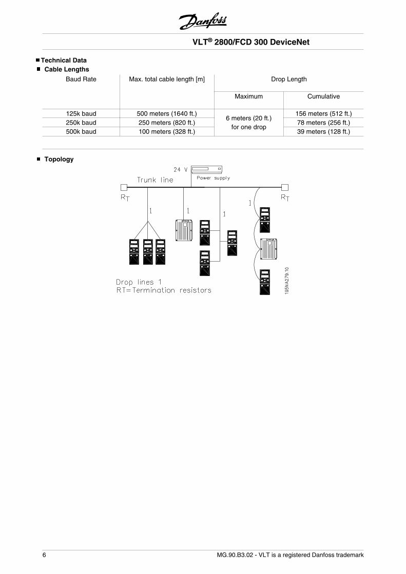
Topology
VLT® 2800/FCD 300 DeviceNet
6 MG.90.B3.02 - VLT is a registered Danfoss trademark
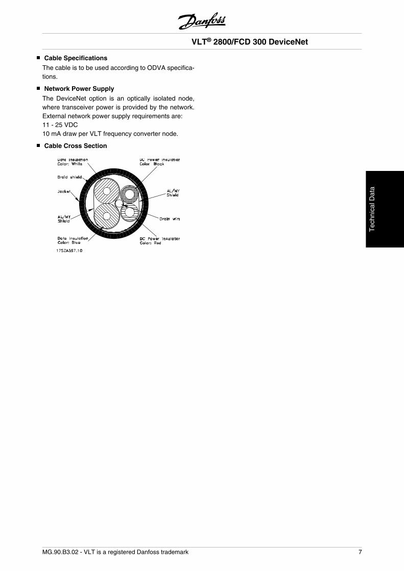
Cable Specifications
The cable is to be used according to ODVA specifica-tions.
Network Power Supply
The DeviceNet option is an optically isolated node,where transceiver power is provided by the network.External network power supply requirements are:11 - 25 VDC10 mA draw per VLT frequency converter node.
Cable Cross Section
VLT® 2800/FCD 300 DeviceNet
MG.90.B3.02 - VLT is a registered Danfoss trademark 7
Tec
hnic
al D
ata
EMC Precautions
The following EMC precautions are recommended toobtain interference free operation of the DeviceNetnetwork. Additional information on EMC can be foundin the FCD 300 and in the VLT 2800 Series OperatingInstructions and Design Guide.
NB!Relevant national and local regulations,for example regarding protective earthconnection, must be observed.
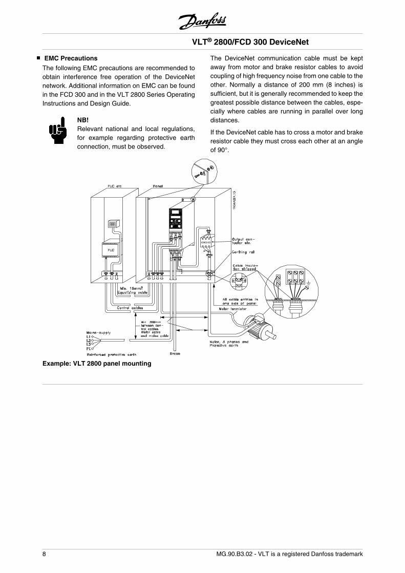
The DeviceNet communication cable must be keptaway from motor and brake resistor cables to avoidcoupling of high frequency noise from one cable to theother. Normally a distance of 200 mm (8 inches) issufficient, but it is generally recommended to keep thegreatest possible distance between the cables, espe-cially where cables are running in parallel over longdistances.
If the DeviceNet cable has to cross a motor and brakeresistor cable they must cross each other at an angleof 90°.
Example: VLT 2800 panel mounting
VLT® 2800/FCD 300 DeviceNet
8 MG.90.B3.02 - VLT is a registered Danfoss trademark
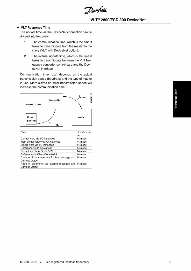
VLT Response Time
The update time via the DeviceNet connection can bedivided into two parts:
1. The communication time, which is the time ittakes to transmit data from the master to theslave (VLT with DeviceNet option).
2. The internal update time, which is the time ittakes to transmit data between the VLT fre-quency converter control card and the Devi-ceNet interface.
Communication time (tcom) depends on the actualtransmission speed (baudrate) and the type of masterin use. More slaves or lower transmission speed willincrease the communication time.
Data Update time,tint
Control word via I/O instances 14 msecMain actual value via I/O instances 44 msecStatus word via I/O instances 14 msecReference via I/O instances 44 msecControl via Class Code 0x29 14 msecReference via Class Code 0x2A 44 msecChange of parameter via Explicit message andDanfoss Object
94 msec
Read of parameter via Explicit message andDanfoss Object
14 msec
VLT® 2800/FCD 300 DeviceNet
MG.90.B3.02 - VLT is a registered Danfoss trademark 9
Tec
hnic
al D
ata
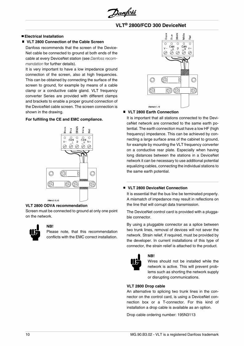
Electrical InstallationVLT 2800 Connection of the Cable Screen
Danfoss recommends that the screen of the Device-Net cable be connected to ground at both ends of thecable at every DeviceNet station (see Danfoss recom-mendation for further details).It is very important to have a low impedance groundconnection of the screen, also at high frequencies.This can be obtained by connecting the surface of thescreen to ground, for example by means of a cableclamp or a conductive cable gland. VLT frequencyconverter Series are provided with different clampsand brackets to enable a proper ground connection ofthe DeviceNet cable screen. The screen connection isshown in the drawing.
For fulfilling the CE and EMC compliance.
VLT 2800 ODVA recommendationScreen must be connected to ground at only one pointon the network.
NB!Please note, that this recommendationconflicts with the EMC correct installation.
VLT 2800 Earth Connection
It is important that all stations connected to the Devi-ceNet network are connected to the same earth po-tential. The earth connection must have a low HF (highfrequency) impedance. This can be achieved by con-necting a large surface area of the cabinet to ground,for example by mounting the VLT frequency converteron a conductive rear plate. Especially when havinglong distances between the stations in a DeviceNetnetwork it can be necessary to use additional potentialequalizing cables, connecting the individual stations tothe same earth potential.
VLT 2800 DeviceNet Connection
It is essential that the bus line be terminated properly.A mismatch of impedance may result in reflections onthe line that will corrupt data transmission.
The DeviceNet control card is provided with a plugga-ble connector.
By using a pluggable connector as a splice betweentwo trunk lines, removal of devices will not sever thenetwork. Strain relief, if required, must be provided bythe developer. In current installations of this type ofconnector, the strain relief is attached to the product.
NB!Wires should not be installed while thenetwork is active. This will prevent prob-lems such as shorting the network supplyor disrupting communications.
VLT 2800 Drop cableAn alternative to splicing two trunk lines in the con-nector on the control card, is using a DeviceNet con-nection box or a T-connector. For this kind ofinstallation a drop cable is available as an option.
Drop cable ordering number: 195N3113
VLT® 2800/FCD 300 DeviceNet
10 MG.90.B3.02 - VLT is a registered Danfoss trademark
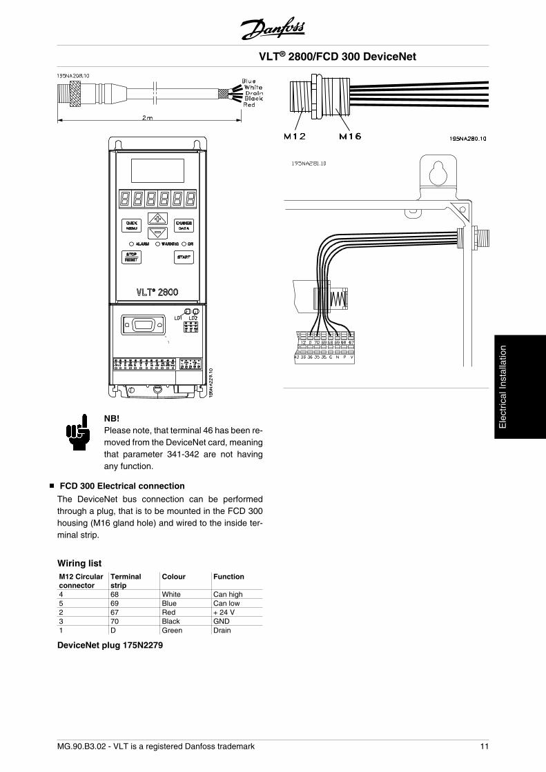
NB!Please note, that terminal 46 has been re-moved from the DeviceNet card, meaningthat parameter 341-342 are not havingany function.
FCD 300 Electrical connection
The DeviceNet bus connection can be performedthrough a plug, that is to be mounted in the FCD 300housing (M16 gland hole) and wired to the inside ter-minal strip.
Wiring listM12 Circularconnector
Terminalstrip
Colour Function
4 68 White Can high5 69 Blue Can low2 67 Red + 24 V3 70 Black GND1 D Green Drain
DeviceNet plug 175N2279
VLT® 2800/FCD 300 DeviceNet
MG.90.B3.02 - VLT is a registered Danfoss trademark 11
Ele
ctric
al In
stal
latio
n
User Interface
The DeviceNet control card contains two bi-color (green/red) LED's for each connector hookup port, to indicatethe state of the device and network, respectively.
Module LED:LD1 on VLT 2800 Dual colour (Green/Red)
Yellow FCD 300 STATUS LED when se-lected as DeviceNet in parameter 26
VLT status
OFF OFF Device is OFFGREEN YELLOW Device is operationalFlashing GREEN Flashing YELLOW Device is in standbyFlashing RED OFF Device detects a recoverable faultRED OFF Device detects an unrecoverable faultFlashing GREEN/RED Flashing YELLOW Device is self testing
NETWORK LED:VLT status LD2 on VLT 2800 Dual colour
(Green/Red)Green BUS LED on FCD 300 VLT status
Network is non-powered/not on-line
OFF OFF Network is non-powered/not on-line
Network is on-line but not con-nected
Flashing GREEN Flashing GREEN Network is on-line but not con-nected
Network is on-line and connec-ted
GREEN GREEN Network is on-line and connec-ted
Network has a connection time-out
Flashing RED OFF Network has a connection time-out
Network has a critical link failure RED OFF Network has a critical link failure
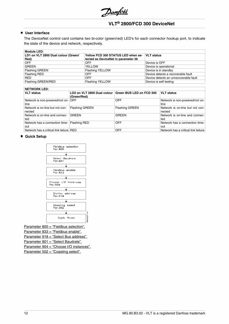
Quick Setup
Parameter 800 = “Fieldbus selection“.Parameter 833 = “Fieldbus enable”.Parameter 918 = “Select Bus address”.Parameter 801 = “Select Baudrate”.Parameter 904 = “Choose I/O instances”.Parameter 502 = “Coasting select”.
VLT® 2800/FCD 300 DeviceNet
12 MG.90.B3.02 - VLT is a registered Danfoss trademark
Master-Slave configurationSystem configuration
The SYSTEM configuration of a DeviceNet master anda VLT 2800/FCD 300 can be split up into two parts.
The first part is the setting of DeviceNet communica-tion related parameters. These are the baud rate andstation address/MAC ID.By VLT 2800/FCD 300 these parameters can be setby the LCP or access via a DeviceNet configurationtool. None of these parameters can be set by mechan-ical switches.After the baud rate and station address/MAC ID areset a connection to a DeviceNet DeviceNet configura-tion tool can be established.
The second and larger area of a SYSTEM configura-tion is the setting of application related parameters.EDS files are easy to create and it is strongly recom-mended to generate an EDS for each VLT 2800/FCD300. This can be done by uploading the EDS file fromeach drive by a DeviceNet configuration tool. In theVLT 2800/FCD 300 EDS file it is possible to configuredthe drive and read or write to parameters. The lan-guage of the EDS file is depending of the actual settingof parameter 001 Language.In parameter 838 EDS Data type it is possible to choosebetween two dataformat for uploading EDS files. Be-fore uploading the EDS file please check if the mastersupport Errata 1 or Errata 2.For Off-line configuration Danfoss can provide youwith english EDS files, see section EDS files for theEDS file name. Contact your local Danfoss supplier forthe EDS files.
Another important configuration parameter is the se-lection of communication mechanisms that enable anefficient and responsive I/O SYSTEM. By VLT 2800/FCD 300 it is possible to choose between the followingcommunication mechanisms:
• Poll I/O
• Bit Strobe I/O
• Change-of-state (COS) / Cyclic I/O
• Explicit Messaging
See DeviceNet Operation Mode in this manual for fur-ther information.
The last configuration parameter is the choice of In-stance type in parameter 904 PPO selection. Here is itpossible to select beween a Danfoss Specific profile(Instance 100/150 or 101/151) or a ODVA Specific ACDrive profile (Instance 20/70 or 21/71).
VLT® 2800/FCD 300 DeviceNet
MG.90.B3.02 - VLT is a registered Danfoss trademark 13
Mas
ter-
Sla
ve c
onfig
ura-
tion
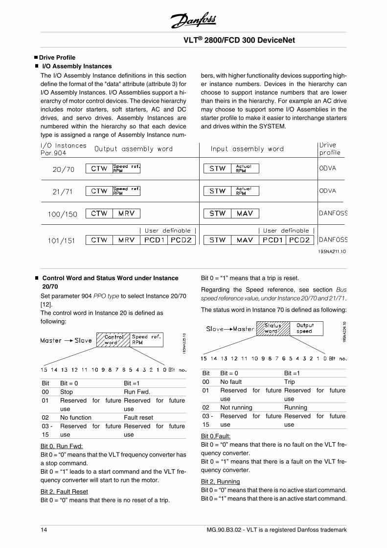
Drive ProfileI/O Assembly Instances
The I/O Assembly Instance definitions in this sectiondefine the format of the "data" attribute (attribute 3) forI/O Assembly Instances. I/O Assemblies support a hi-erarchy of motor control devices. The device hierarchyincludes motor starters, soft starters, AC and DCdrives, and servo drives. Assembly Instances arenumbered within the hierarchy so that each devicetype is assigned a range of Assembly Instance num-
bers, with higher functionality devices supporting high-er instance numbers. Devices in the hierarchy canchoose to support instance numbers that are lowerthan theirs in the hierarchy. For example an AC drivemay choose to support some I/O Assemblies in thestarter profile to make it easier to interchange startersand drives within the SYSTEM.
Control Word and Status Word under Instance20/70
Set parameter 904 PPO type to select Instance 20/70[12].The control word in Instance 20 is defined asfollowing:
Bit Bit = 0 Bit =100 Stop Run Fwd.01 Reserved for future
useReserved for futureuse
02 No function Fault reset03 -15
Reserved for futureuse
Reserved for futureuse
Bit 0, Run Fwd:Bit 0 = “0” means that the VLT frequency converter hasa stop command.Bit 0 = “1” leads to a start command and the VLT fre-quency converter will start to run the motor.
Bit 2, Fault ResetBit 0 = “0” means that there is no reset of a trip.
Bit 0 = “1” means that a trip is reset.
Regarding the Speed reference, see section Busspeed reference value, under Instance 20/70 and 21/71.
The status word in Instance 70 is defined as following:
Bit Bit = 0 Bit =100 No fault Trip01 Reserved for future
useReserved for futureuse
02 Not running Running03 -15
Reserved for futureuse
Reserved for futureuse
Bit 0,Fault:Bit 0 = “0” means that there is no fault on the VLT fre-quency converter.Bit 0 = “1” means that there is a fault on the VLT fre-quency converter.
Bit 2, RunningBit 0 = “0” means that there is no active start command.Bit 0 = “1” means that there is an active start command.
VLT® 2800/FCD 300 DeviceNet
14 MG.90.B3.02 - VLT is a registered Danfoss trademark
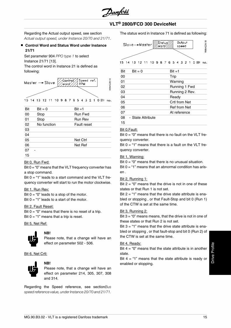
Regarding the Actual output speed, see sectionActual output speed, under Instance 20/70 and 21/71.
Control Word and Status Word under Instance21/71
Set parameter 904 PPO type 1 to selectInstance 21/71 [13].The control word in Instance 21 is defined asfollowing:
Bit Bit = 0 Bit =100 Stop Run Fwd01 Stop Run Rev02 No function Fault reset03 04 05 Net Ctrl06 Net Ref07 -15
Bit 0, Run Fwd:Bit 0 = “0” means that the VLT frequency converter hasa stop command.Bit 0 = “1” leads to a start command and the VLT fre-quency converter will start to run the motor clockwise.
Bit 1, Run Rev:Bit 0 = “0” leads to a stop of the motor.Bit 0 = “1” leads to a start of the motor.
Bit 2, Fault Reset:Bit 0 = “0” means that there is no reset of a trip.Bit 0 = “1” means that a trip is reset.
Bit 5, Net Ref:
NB!Please note, that a change will have aneffect on parameter 502 - 506.
Bit 6, Net Crtl:
NB!Please note, that a change will have aneffect on parameter 214, 305, 307, 308and 314.
Regarding the Speed reference, see sectionBusspeed reference value, under Instance 20/70 and 21/71.
The status word in Instance 71 is defined as following:
Bit Bit = 0 Bit =100 Trip01 Warning02 Running 1 Fwd03 Running 2 Rev.04 Ready05 Crtl from Net06 Ref from Net07 At reference08 -15
State Attribute
Bit 0,Fault:Bit 0 = “0” means that there is no fault on the VLT fre-quency converter.Bit 0 = “1” means that there is a fault on the VLT fre-quency converter.
Bit 1, Warning:Bit 0 = “0” means that there is no unusual situation.Bit 0 = “1” means that an abnormal condition has aris-en .
Bit 2, Running 1:Bit 2 = “0” means that the drive is not in one of thesestates or that Run 1 is not set.Bit 2 = “1” means that the drive state attribute is ena-bled or stopping , or that Fault-Stop and bit 0 (Run 1)of the CTW is set at the same time.
Bit 3, Running 2:Bit 3 = “0” means means, that the drive is not in one ofthese states or that Run 2 is not set.Bit 3 = “1” means that the drive state attribute is ena-bled or stopping , or that fault-stop and bit 0 (Run 2) ofthe CTW is set at the same time.
Bit 4, Ready:Bit 4 = “0” means that the state attribute is in anotherstate.Bit 4 = “1” means that the state attribute is ready orenabled or stopping.
VLT® 2800/FCD 300 DeviceNet
MG.90.B3.02 - VLT is a registered Danfoss trademark 15
Driv
e P
rofil
e
Bit 5, Control from net:Bit 5 = “0” means that the drive is controlled from thestandard inputs.Bit 5 = “1” means that Devicenet has the control (start,stop, reverse) of the drive.
Bit 6, Ref from Net:Bit 6 = “0” means that the reference comes from thedrive's inputs.Bit 6 = “1” means that the reference is coming fromDevicenet.
Bit 7, At reference:Bit 7 = “0” means that the motor is running, but that thepresent speed is different from the preset speed ref-erence, i.e. while the speed is being ramped up/downduring start/stop.Bit 7 = “1” means that the drive's speed equals the ref-erence.
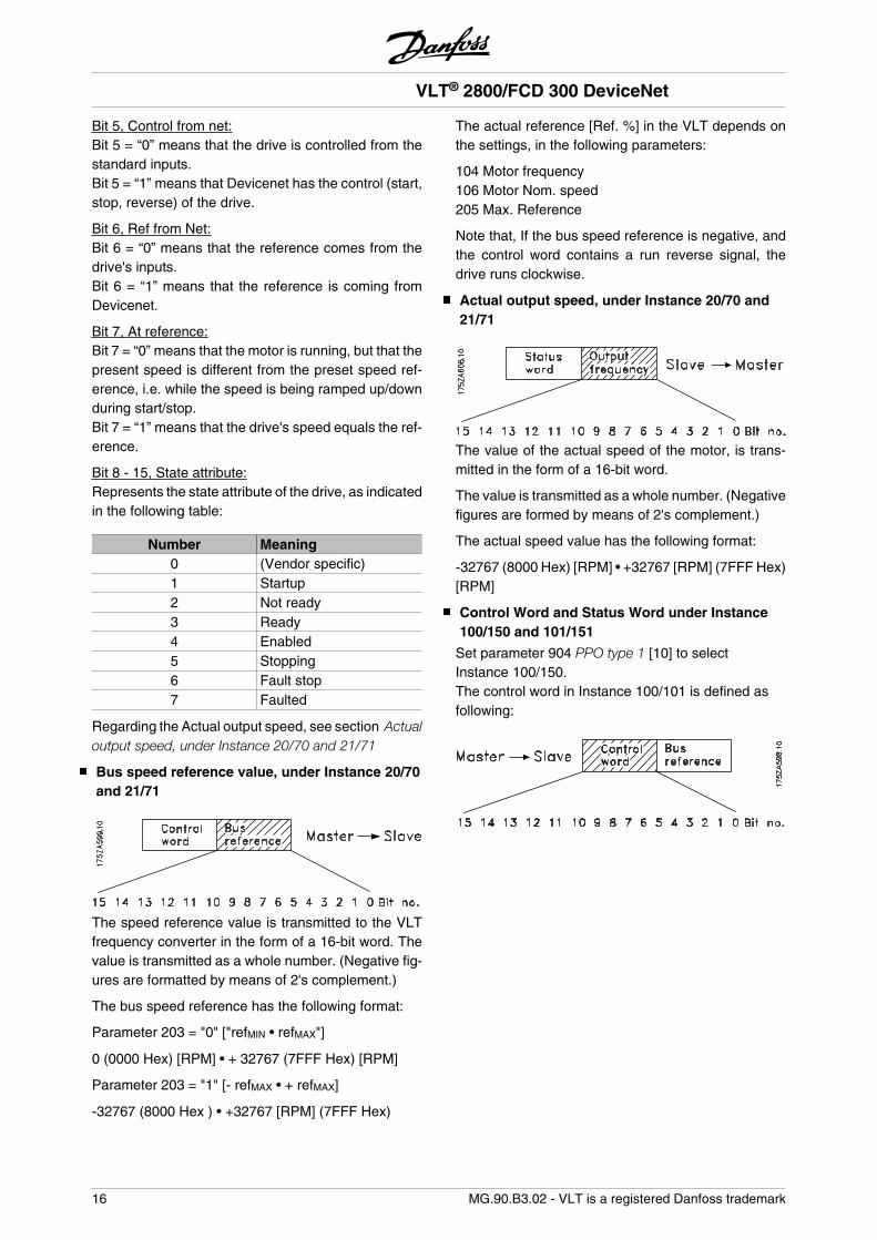
Bit 8 - 15, State attribute:Represents the state attribute of the drive, as indicatedin the following table:
Number Meaning0 (Vendor specific)1 Startup2 Not ready3 Ready4 Enabled5 Stopping6 Fault stop7 Faulted
Regarding the Actual output speed, see section Actualoutput speed, under Instance 20/70 and 21/71
Bus speed reference value, under Instance 20/70and 21/71
The speed reference value is transmitted to the VLTfrequency converter in the form of a 16-bit word. Thevalue is transmitted as a whole number. (Negative fig-ures are formatted by means of 2's complement.)
The bus speed reference has the following format:
Parameter 203 = "0" ["refMIN • refMAX"]
0 (0000 Hex) [RPM] • + 32767 (7FFF Hex) [RPM]
Parameter 203 = "1" [- refMAX • + refMAX]
-32767 (8000 Hex ) • +32767 [RPM] (7FFF Hex)
The actual reference [Ref. %] in the VLT depends onthe settings, in the following parameters:
104 Motor frequency106 Motor Nom. speed205 Max. Reference
Note that, If the bus speed reference is negative, andthe control word contains a run reverse signal, thedrive runs clockwise.
Actual output speed, under Instance 20/70 and21/71
The value of the actual speed of the motor, is trans-mitted in the form of a 16-bit word.
The value is transmitted as a whole number. (Negativefigures are formed by means of 2's complement.)
The actual speed value has the following format:
-32767 (8000 Hex) [RPM] • +32767 [RPM] (7FFF Hex)[RPM]
Control Word and Status Word under Instance100/150 and 101/151
Set parameter 904 PPO type 1 [10] to selectInstance 100/150.The control word in Instance 100/101 is defined asfollowing:
VLT® 2800/FCD 300 DeviceNet
16 MG.90.B3.02 - VLT is a registered Danfoss trademark
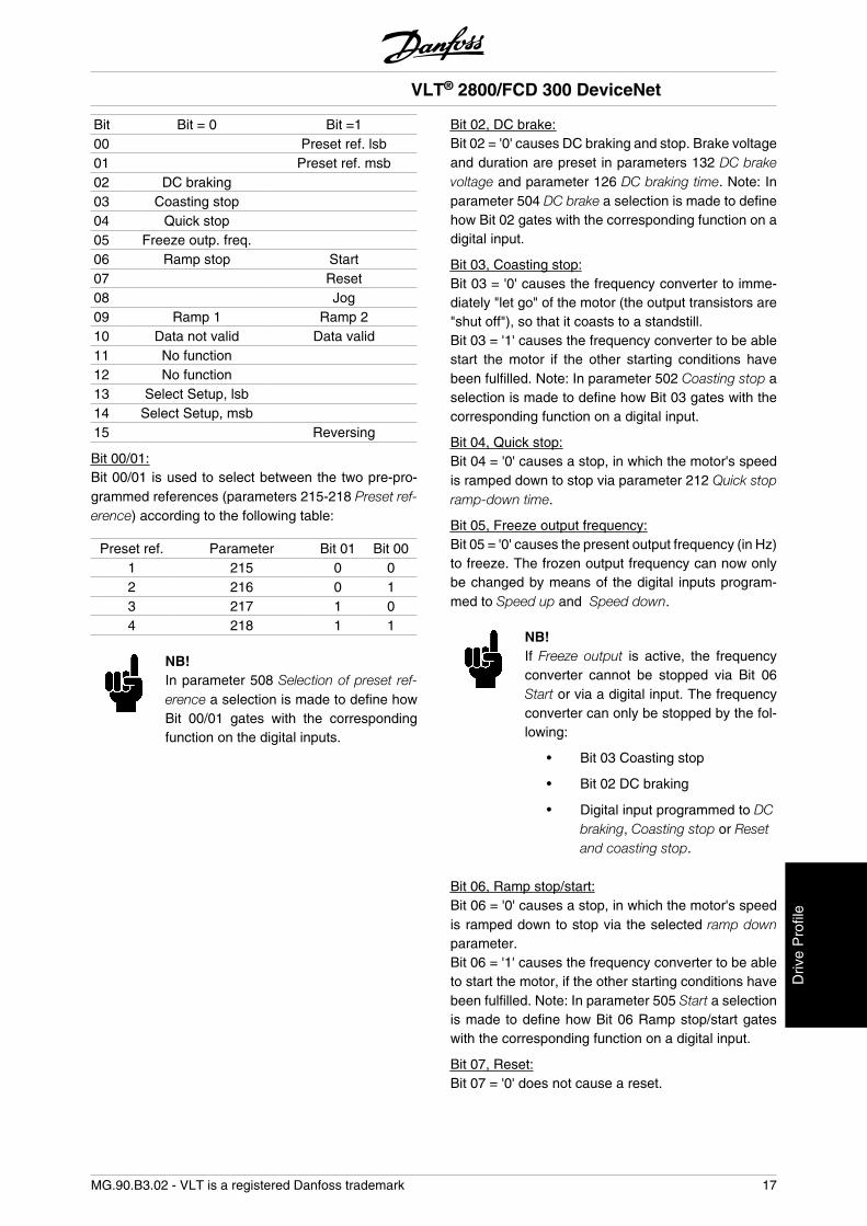
Bit Bit = 0 Bit =100 Preset ref. lsb01 Preset ref. msb02 DC braking 03 Coasting stop 04 Quick stop 05 Freeze outp. freq. 06 Ramp stop Start07 Reset08 Jog09 Ramp 1 Ramp 210 Data not valid Data valid11 No function 12 No function 13 Select Setup, lsb 14 Select Setup, msb 15 Reversing
Bit 00/01:Bit 00/01 is used to select between the two pre-pro-grammed references (parameters 215-218 Preset ref-erence) according to the following table:
Preset ref. Parameter Bit 01 Bit 001 215 0 02 216 0 13 217 1 04 218 1 1
NB!In parameter 508 Selection of preset ref-erence a selection is made to define howBit 00/01 gates with the correspondingfunction on the digital inputs.
Bit 02, DC brake:Bit 02 = '0' causes DC braking and stop. Brake voltageand duration are preset in parameters 132 DC brakevoltage and parameter 126 DC braking time. Note: Inparameter 504 DC brake a selection is made to definehow Bit 02 gates with the corresponding function on adigital input.
Bit 03, Coasting stop:Bit 03 = '0' causes the frequency converter to imme-diately "let go" of the motor (the output transistors are"shut off"), so that it coasts to a standstill.Bit 03 = '1' causes the frequency converter to be ablestart the motor if the other starting conditions havebeen fulfilled. Note: In parameter 502 Coasting stop aselection is made to define how Bit 03 gates with thecorresponding function on a digital input.
Bit 04, Quick stop:Bit 04 = '0' causes a stop, in which the motor's speedis ramped down to stop via parameter 212 Quick stopramp-down time.
Bit 05, Freeze output frequency:Bit 05 = '0' causes the present output frequency (in Hz)to freeze. The frozen output frequency can now onlybe changed by means of the digital inputs program-med to Speed up and Speed down.
NB!If Freeze output is active, the frequencyconverter cannot be stopped via Bit 06Start or via a digital input. The frequencyconverter can only be stopped by the fol-lowing:
• Bit 03 Coasting stop
• Bit 02 DC braking
• Digital input programmed to DCbraking, Coasting stop or Resetand coasting stop.
Bit 06, Ramp stop/start:Bit 06 = '0' causes a stop, in which the motor's speedis ramped down to stop via the selected ramp downparameter.Bit 06 = '1' causes the frequency converter to be ableto start the motor, if the other starting conditions havebeen fulfilled. Note: In parameter 505 Start a selectionis made to define how Bit 06 Ramp stop/start gateswith the corresponding function on a digital input.
Bit 07, Reset:Bit 07 = '0' does not cause a reset.
VLT® 2800/FCD 300 DeviceNet
MG.90.B3.02 - VLT is a registered Danfoss trademark 17
Driv
e P
rofil
e
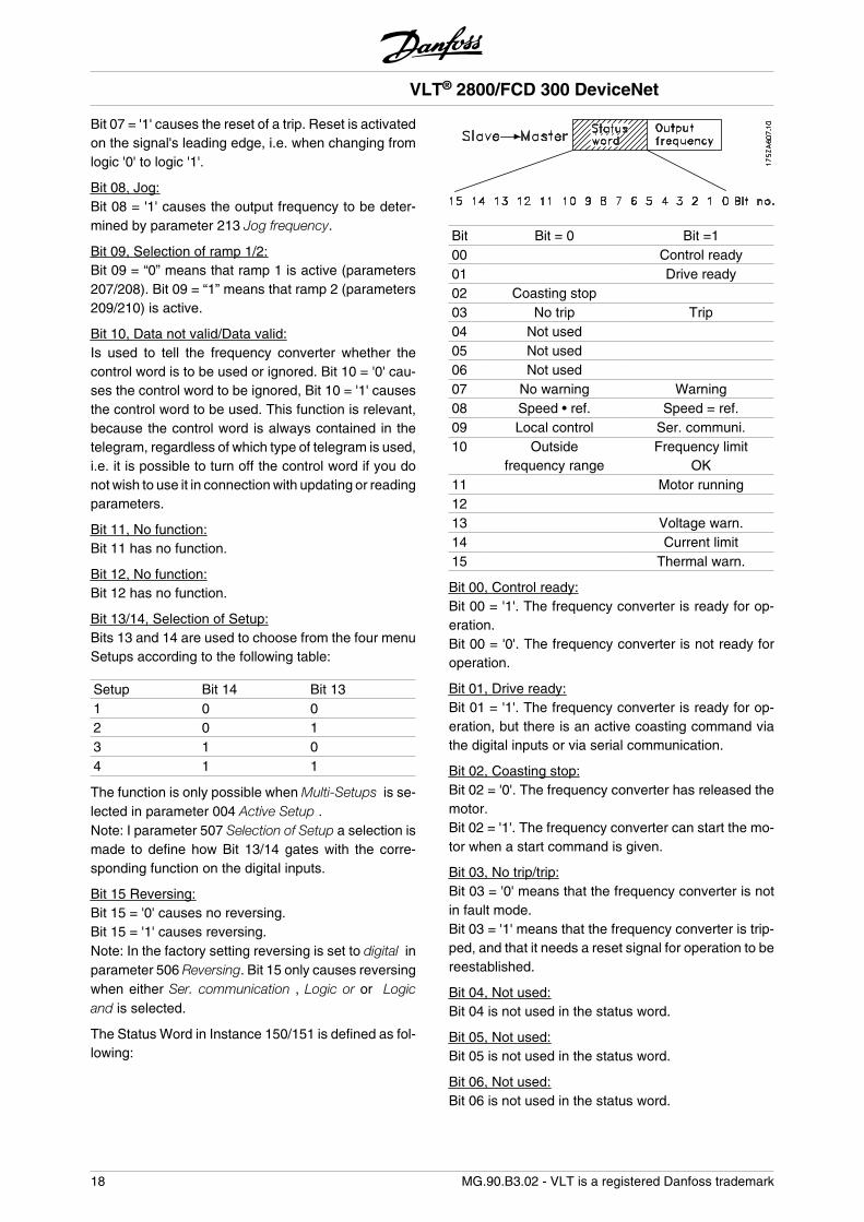
Bit 07 = '1' causes the reset of a trip. Reset is activatedon the signal's leading edge, i.e. when changing fromlogic '0' to logic '1'.
Bit 08, Jog:Bit 08 = '1' causes the output frequency to be deter-mined by parameter 213 Jog frequency.
Bit 09, Selection of ramp 1/2:Bit 09 = “0” means that ramp 1 is active (parameters207/208). Bit 09 = “1” means that ramp 2 (parameters209/210) is active.
Bit 10, Data not valid/Data valid:Is used to tell the frequency converter whether thecontrol word is to be used or ignored. Bit 10 = '0' cau-ses the control word to be ignored, Bit 10 = '1' causesthe control word to be used. This function is relevant,because the control word is always contained in thetelegram, regardless of which type of telegram is used,i.e. it is possible to turn off the control word if you donot wish to use it in connection with updating or readingparameters.
Bit 11, No function:Bit 11 has no function.
Bit 12, No function:Bit 12 has no function.
Bit 13/14, Selection of Setup:Bits 13 and 14 are used to choose from the four menuSetups according to the following table:
Setup Bit 14 Bit 131 0 02 0 13 1 04 1 1
The function is only possible when Multi-Setups is se-lected in parameter 004 Active Setup .Note: I parameter 507 Selection of Setup a selection ismade to define how Bit 13/14 gates with the corre-sponding function on the digital inputs.
Bit 15 Reversing:Bit 15 = '0' causes no reversing.Bit 15 = '1' causes reversing.Note: In the factory setting reversing is set to digital inparameter 506 Reversing. Bit 15 only causes reversingwhen either Ser. communication , Logic or or Logicand is selected.
The Status Word in Instance 150/151 is defined as fol-lowing:
Bit Bit = 0 Bit =100 Control ready01 Drive ready02 Coasting stop 03 No trip Trip04 Not used 05 Not used 06 Not used 07 No warning Warning08 Speed • ref. Speed = ref.09 Local control Ser. communi.10 Outside
frequency rangeFrequency limit
OK11 Motor running12 13 Voltage warn.14 Current limit15 Thermal warn.
Bit 00, Control ready:Bit 00 = '1'. The frequency converter is ready for op-eration.Bit 00 = '0'. The frequency converter is not ready foroperation.
Bit 01, Drive ready:Bit 01 = '1'. The frequency converter is ready for op-eration, but there is an active coasting command viathe digital inputs or via serial communication.
Bit 02, Coasting stop:Bit 02 = '0'. The frequency converter has released themotor.Bit 02 = '1'. The frequency converter can start the mo-tor when a start command is given.
Bit 03, No trip/trip:Bit 03 = '0' means that the frequency converter is notin fault mode.Bit 03 = '1' means that the frequency converter is trip-ped, and that it needs a reset signal for operation to bereestablished.
Bit 04, Not used:Bit 04 is not used in the status word.
Bit 05, Not used:Bit 05 is not used in the status word.
Bit 06, Not used:Bit 06 is not used in the status word.
VLT® 2800/FCD 300 DeviceNet
18 MG.90.B3.02 - VLT is a registered Danfoss trademark
Bit 07, No warning/warning:Bit 07 = '0' means that there are no warnings.Bit 07 = '1' means that a warning has occurred.
Bit 08, Speed• ref/speed = ref.:Bit 08 = '0' means that the motor is running, but thatthe present speed is different from the preset speedreference. It might, for example, be the case while thespeed is being ramped up/down during start/stop.Bit 08 = '1' means that the motor's present speed is thesame as the preset speed reference.
Bit 09, Local operation/serial communication control:Bit 09 = '0' means that [STOP/RESET] is activated onthe control unit, or that Local control in parameter 002Local/remote operation is selected. It is not possible tocontrol the frequency converter via serial communica-tion.Bit 09 = '1' means that it is possible to control the fre-quency converter via serial communication.
Bit 10, Outside frequency range:Bit 10 = '0', if the output frequency has reached thevalue in parameter 201 Output frequency low limit orparameter 202 Output frequency high limit. Bit 10 = "1"means that the output frequency is within the definedlimits.
Bit 11, Running/not running:Bit 11 = '0' means that the motor is not running.Bit 11 = '1' means that the frequency converter has astart signal or that the output frequency is greater than0 Hz.
Bit 13, Voltage warning high/low:Bit 13 = '0' means that there are no voltage warnings.Bit 13 = '1' means that the DC voltage in the frequencyconverter's intermediate circuit is too low or too high.
Bit 14, Current limit:Bit 14 = '0' means that the output current is less thanthe value in parameter 221 Current Limit ILIM .Bit 14 = '1' means that the output current is greater thanthe value in parameter 221 Current LimitILIM and thatthe frequency converter will trip after a set period oftime.
Bit 15, Thermal warning:Bit 15 = '0' means that there is no thermal warning.Bit 15 = '1' means that the temperature limit has beenexceeded in either the motor, frequency converter orfrom a thermistor that is connected to a digital input.
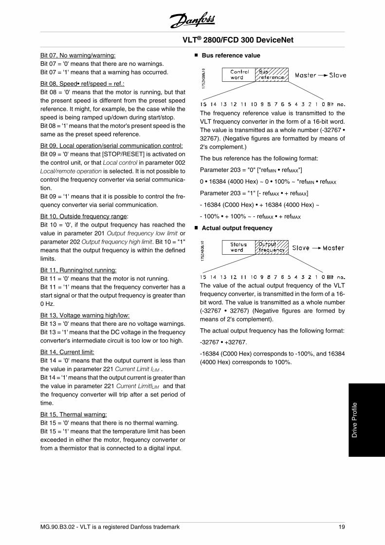
Bus reference value
The frequency reference value is transmitted to theVLT frequency converter in the form of a 16-bit word.The value is transmitted as a whole number (-32767 •32767). (Negative figures are formatted by means of2's complement.)
The bus reference has the following format:
Parameter 203 = "0" ["refMIN • refMAX"]
0 • 16384 (4000 Hex) ~ 0 • 100% ~ "refMIN • refMAX
Parameter 203 = "1" [- refMAX • + refMAX]
- 16384 (C000 Hex) • + 16384 (4000 Hex) ~
- 100% • + 100% ~ - refMAX • + refMAX
Actual output frequency
The value of the actual output frequency of the VLTfrequency converter, is transmitted in the form of a 16-bit word. The value is transmitted as a whole number(-32767 • 32767) (Negative figures are formed bymeans of 2's complement).
The actual output frequency has the following format:
-32767 • +32767.
-16384 (C000 Hex) corresponds to -100%, and 16384(4000 Hex) corresponds to 100%.
VLT® 2800/FCD 300 DeviceNet
MG.90.B3.02 - VLT is a registered Danfoss trademark 19
Driv
e P
rofil
e
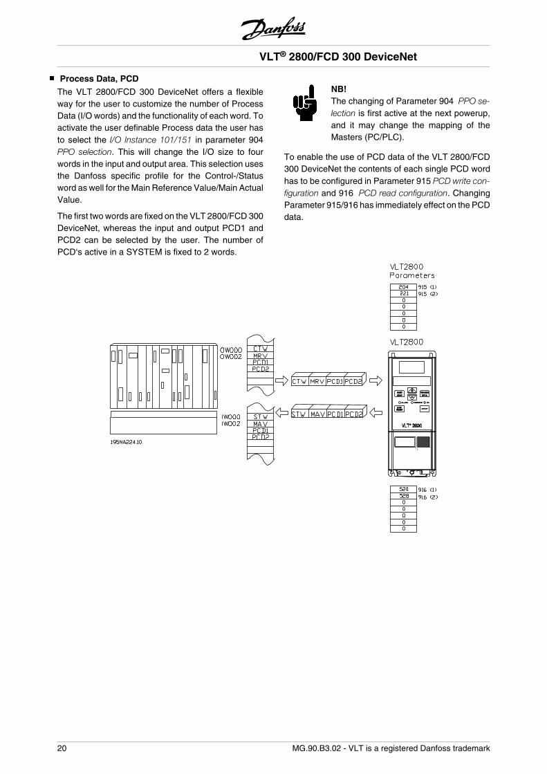
Process Data, PCD
The VLT 2800/FCD 300 DeviceNet offers a flexibleway for the user to customize the number of ProcessData (I/O words) and the functionality of each word. Toactivate the user definable Process data the user hasto select the I/O Instance 101/151 in parameter 904PPO selection. This will change the I/O size to fourwords in the input and output area. This selection usesthe Danfoss specific profile for the Control-/Statusword as well for the Main Reference Value/Main ActualValue.
The first two words are fixed on the VLT 2800/FCD 300DeviceNet, whereas the input and output PCD1 andPCD2 can be selected by the user. The number ofPCD‘s active in a SYSTEM is fixed to 2 words.
NB!The changing of Parameter 904 PPO se-lection is first active at the next powerup,and it may change the mapping of theMasters (PC/PLC).
To enable the use of PCD data of the VLT 2800/FCD300 DeviceNet the contents of each single PCD wordhas to be configured in Parameter 915 PCD write con-figuration and 916 PCD read configuration. ChangingParameter 915/916 has immediately effect on the PCDdata.
VLT® 2800/FCD 300 DeviceNet
20 MG.90.B3.02 - VLT is a registered Danfoss trademark
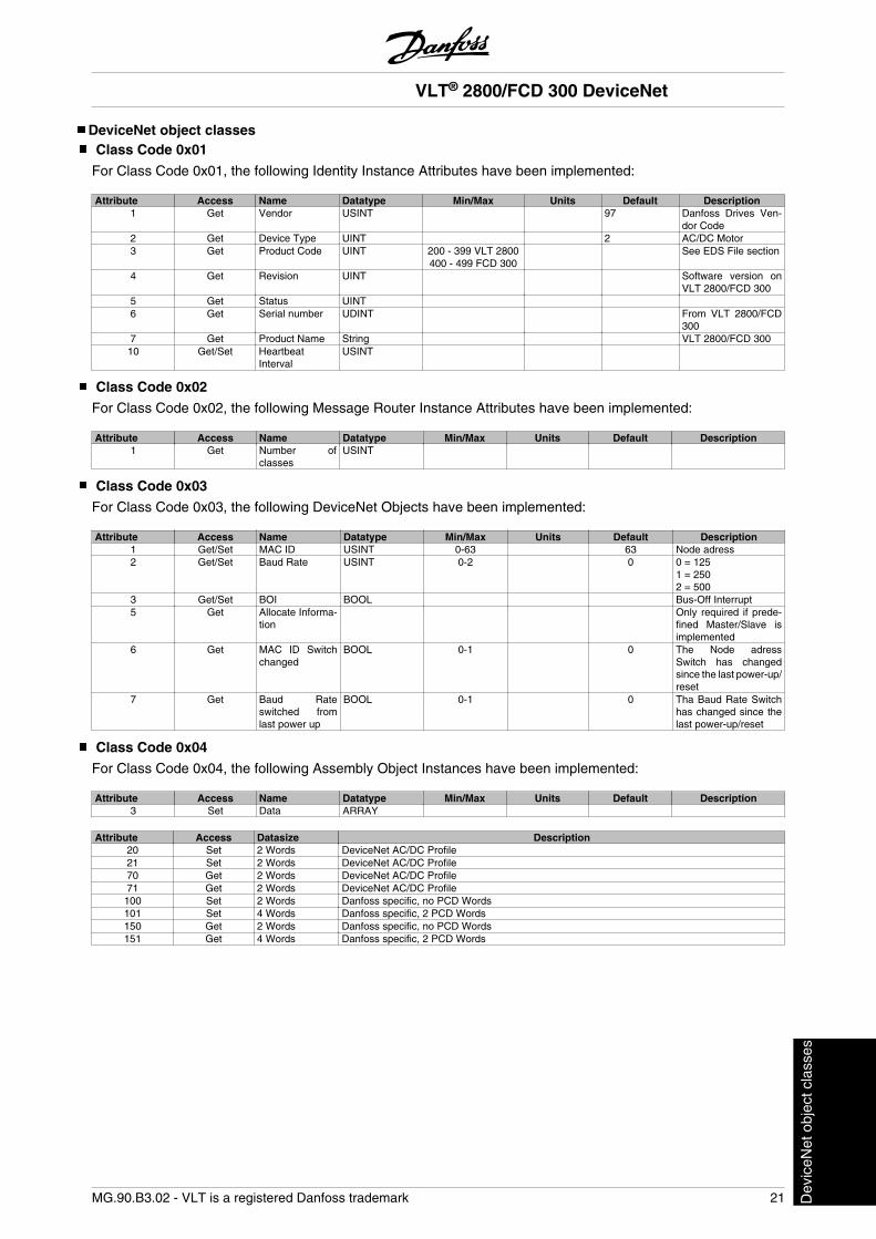
DeviceNet object classesClass Code 0x01
For Class Code 0x01, the following Identity Instance Attributes have been implemented:
Attribute Access Name Datatype Min/Max Units Default Description1 Get Vendor USINT 97 Danfoss Drives Ven-
dor Code2 Get Device Type UINT 2 AC/DC Motor3 Get Product Code UINT 200 - 399 VLT 2800
400 - 499 FCD 300 See EDS File section
4 Get Revision UINT Software version onVLT 2800/FCD 300
5 Get Status UINT 6 Get Serial number UDINT From VLT 2800/FCD
3007 Get Product Name String VLT 2800/FCD 30010 Get/Set Heartbeat
IntervalUSINT
Class Code 0x02
For Class Code 0x02, the following Message Router Instance Attributes have been implemented:
Attribute Access Name Datatype Min/Max Units Default Description1 Get Number of
classesUSINT
Class Code 0x03
For Class Code 0x03, the following DeviceNet Objects have been implemented:
Attribute Access Name Datatype Min/Max Units Default Description1 Get/Set MAC ID USINT 0-63 63 Node adress2 Get/Set Baud Rate USINT 0-2 0 0 = 125
1 = 2502 = 500
3 Get/Set BOI BOOL Bus-Off Interrupt5 Get Allocate Informa-
tion Only required if prede-
fined Master/Slave isimplemented
6 Get MAC ID Switchchanged
BOOL 0-1 0 The Node adressSwitch has changedsince the last power-up/reset
7 Get Baud Rateswitched fromlast power up
BOOL 0-1 0 Tha Baud Rate Switchhas changed since thelast power-up/reset
Class Code 0x04
For Class Code 0x04, the following Assembly Object Instances have been implemented:
Attribute Access Name Datatype Min/Max Units Default Description3 Set Data ARRAY
Attribute Access Datasize Description20 Set 2 Words DeviceNet AC/DC Profile21 Set 2 Words DeviceNet AC/DC Profile70 Get 2 Words DeviceNet AC/DC Profile71 Get 2 Words DeviceNet AC/DC Profile100 Set 2 Words Danfoss specific, no PCD Words101 Set 4 Words Danfoss specific, 2 PCD Words150 Get 2 Words Danfoss specific, no PCD Words151 Get 4 Words Danfoss specific, 2 PCD Words
VLT® 2800/FCD 300 DeviceNet
MG.90.B3.02 - VLT is a registered Danfoss trademark 21 Dev
iceN
et o
bjec
t cla
sses
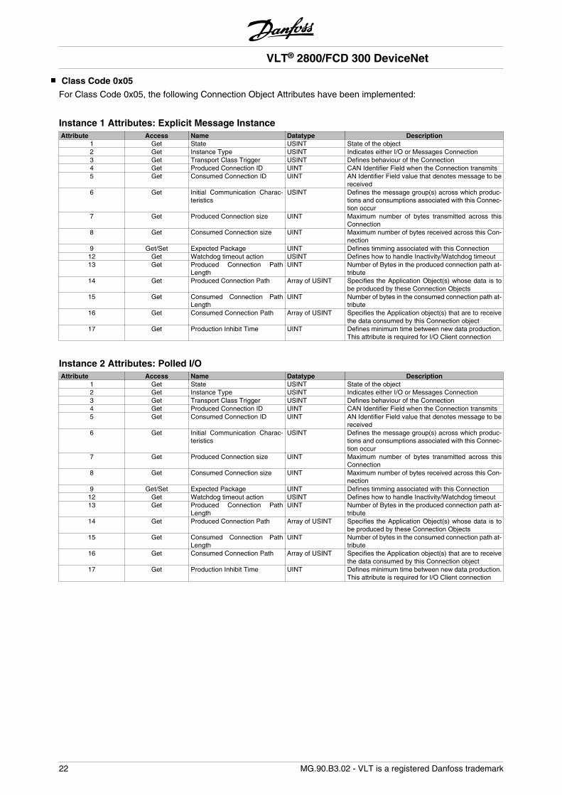
Class Code 0x05
For Class Code 0x05, the following Connection Object Attributes have been implemented:
Instance 1 Attributes: Explicit Message InstanceAttribute Access Name Datatype Description
1 Get State USINT State of the object2 Get Instance Type USINT Indicates either I/O or Messages Connection3 Get Transport Class Trigger USINT Defines behaviour of the Connection4 Get Produced Connection ID UINT CAN Identifier Field when the Connection transmits5 Get Consumed Connection ID UINT AN Identifier Field value that denotes message to be
received6 Get Initial Communication Charac-
teristicsUSINT Defines the message group(s) across which produc-
tions and consumptions associated with this Connec-tion occur
7 Get Produced Connection size UINT Maximum number of bytes transmitted across thisConnection
8 Get Consumed Connection size UINT Maximum number of bytes received across this Con-nection
9 Get/Set Expected Package UINT Defines timming associated with this Connection12 Get Watchdog timeout action USINT Defines how to handle Inactivity/Watchdog timeout13 Get Produced Connection Path
LengthUINT Number of Bytes in the produced connection path at-
tribute14 Get Produced Connection Path Array of USINT Specifies the Application Object(s) whose data is to
be produced by these Connection Objects15 Get Consumed Connection Path
LengthUINT Number of bytes in the consumed connection path at-
tribute16 Get Consumed Connection Path Array of USINT Specifies the Application object(s) that are to receive
the data consumed by this Connection object17 Get Production Inhibit Time UINT Defines minimum time between new data production.
This attribute is required for I/O Client connection
Instance 2 Attributes: Polled I/OAttribute Access Name Datatype Description
1 Get State USINT State of the object2 Get Instance Type USINT Indicates either I/O or Messages Connection3 Get Transport Class Trigger USINT Defines behaviour of the Connection4 Get Produced Connection ID UINT CAN Identifier Field when the Connection transmits5 Get Consumed Connection ID UINT AN Identifier Field value that denotes message to be
received6 Get Initial Communication Charac-
teristicsUSINT Defines the message group(s) across which produc-
tions and consumptions associated with this Connec-tion occur
7 Get Produced Connection size UINT Maximum number of bytes transmitted across thisConnection
8 Get Consumed Connection size UINT Maximum number of bytes received across this Con-nection
9 Get/Set Expected Package UINT Defines timming associated with this Connection12 Get Watchdog timeout action USINT Defines how to handle Inactivity/Watchdog timeout13 Get Produced Connection Path
LengthUINT Number of Bytes in the produced connection path at-
tribute14 Get Produced Connection Path Array of USINT Specifies the Application Object(s) whose data is to
be produced by these Connection Objects15 Get Consumed Connection Path
LengthUINT Number of bytes in the consumed connection path at-
tribute16 Get Consumed Connection Path Array of USINT Specifies the Application object(s) that are to receive
the data consumed by this Connection object17 Get Production Inhibit Time UINT Defines minimum time between new data production.
This attribute is required for I/O Client connection
VLT® 2800/FCD 300 DeviceNet
22 MG.90.B3.02 - VLT is a registered Danfoss trademark
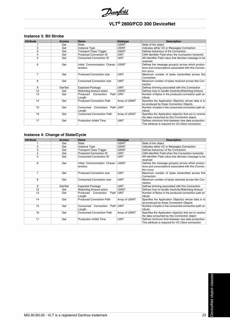
Instance 3: Bit StrobeAttribute Access Name Datatype Description
1 Get State USINT State of the object2 Get Instance Type USINT Indicates either I/O or Messages Connection3 Get Transport Class Trigger USINT Defines behaviour of the Connection4 Get Produced Connection ID UINT CAN Identifier Field when the Connection transmits5 Get Consumed Connection ID UiNT AN Identifier Field value that denotes message to be
received6 Get Initial Communication Charac-
teristicsUSINT Defines the message group(s) across which produc-
tions and consumptions associated with this Connec-tion occur
7 Get Produced Connection size UINT Maximum number of bytes transmitted across thisConnection
8 Get Consumed Connection size UINT Maximum number of bytes received across this Con-nection
9 Get/Set Expected Package UINT Defines timming associated with this Connection12 Get Watchdog timeout action USINT Defines how to handle Inactivity/Watchdog timeout13 Get Produced Connection Path
LengthUINT Number of Bytes in the produced connection path at-
tribute14 Get Produced Connection Path Array of USINT Specifies the Application Object(s) whose data is to
be produced by these Connection Objects15 Get Consumed Connection Path
LengthUINT Number of bytes in the consumed connection path at-
tribute16 Get Consumed Connection Path Array of USINT Specifies the Application object(s) that are to receive
the data consumed by this Connection object17 Get Production Inhibit Time UINT Defines minimum time between new data production.
This attribute is required for I/O Client connection
Instance 4: Change of State/CycleAttribute Access Name Datatype Description
1 Get State USINT State of the object2 Get Instance Type USINT Indicates either I/O or Messages Connection3 Get Transport Class Trigger USINT Defines behaviour of the Connection4 Get Produced Connection ID UINT CAN Identifier Field when the Connection transmits5 Get Consumed Connection ID UiNT AN Identifier Field value that denotes message to be
received6 Get Initial Communication Charac-
teristicsUSINT Defines the message group(s) across which produc-
tions and consumptions associated with this Connec-tion occur
7 Get Produced Connection size UINT Maximum number of bytes transmitted across thisConnection
8 Get Consumed Connection size UINT Maximum number of bytes received across this Con-nection
9 Get/Set Expected Package UINT Defines timming associated with this Connection12 Get Watchdog timeout action USINT Defines how to handle Inactivity/Watchdog timeout13 Get Produced Connection Path
LengthUINT Number of Bytes in the produced connection path at-
tribute14 Get Produced Connection Path Array of USINT Specifies the Application Object(s) whose data is to
be produced by these Connection Objects15 Get Consumed Connection Path
LengthUINT Number of bytes in the consumed connection path at-
tribute16 Get Consumed Connection Path Array of USINT Specifies the Application object(s) that are to receive
the data consumed by this Connection object17 Get Production Inhibit Time UINT Defines minimum time between new data production.
This attribute is required for I/O Client connection
VLT® 2800/FCD 300 DeviceNet
MG.90.B3.02 - VLT is a registered Danfoss trademark 23 Dev
iceN
et o
bjec
t cla
sses
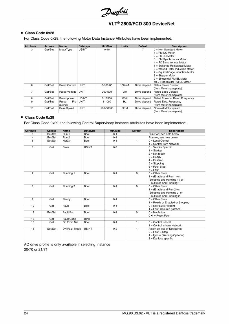
Class Code 0x28
For Class Code 0x28, the following Motor Data Instance Attributes have been implemented:
Attribute Access Name Datatype Min/Max Units Default Description3 Get/Set MotorType USINT 0-10 7 0 = Non Standard Motor
1 = PM DC Motor2 = FC DC Motor3 = PM Synchronous Motor4 = FC Synchronous Motor5 = Switched Reluctance Motor6 = Wound Rotor Induction Motor7 = Squirrel Cage Induction Motor8 = Stepper Motor9 = Sinusoidal PM BL Motor10 = Trapezoidal PM BL Motor
6 Get/Set Rated Current UNIT 0-100.00 100 mA Drive depend Rates Stator Current(from Motor nameplate)
7 Get/Set Rated Voltage UNIT 200-500 Volt Drive depend Rated Base Voltage(from Motor nameplate)
8 Get/Set Rated power UDINT 0-18500 Watt Drive depend Rated Power at Rated Frequency9 Get/Set Rated Fre-
quencyUNIT 1-1000 Hz Drive depend Rated Elec. Frequency
(from Motor nameplate)15 Get/Set Base Speed UNIT 100-60000 RPM Drive depend Nominal Motor speed
(from Motor nameplate)
Class Code 0x29
For Class Code 0x29, the following Control Supervisory Instance Attributes have been implemented:
Attribute Access Name Datatype Min/Max Default Description3 Get/Set Run 1 Bool 0-1 Run Fwd, see note below4 Get/Set Run 2 Bool 0-1 Run rev, see note below5 Get/Set NetCtrl Bool 0-1 1 0 = Local Control
1 = Control from Network6 Get State USINT 0-7 0 = Vendor Specific
1 = Startup2 = Not ready3 = Ready4 = Enabled5 = Stopping6 = Fault Stop7 = Fault
7 Get Running 1 Bool 0-1 0 0 = Other State1 = (Enable and Run 1) or(Stopping and Running 1 ) or(Fault stop and Running 1)
8 Get Running 2 Bool 0-1 0 0 = Other State1 = (Enable and Run 2) or(Stopping and Running 2) or(Fault stop and Running 2)
9 Get Ready Bool 0-1 0 = Other State1 = Ready or Enabled or Stopping
10 Get Fault Bool 0-1 0 = No Faults Present1 = Fault Occured (latched)
12 Get/Set Fault Rst Bool 0-1 0 0 = No Action0 •1 = Reset Fault
13 Get Fault Code UINT 15 Get Crt From Net Bool 0-1 1 0 = Control is local
1 = Control is from Network16 Get/Set DN Fault Mode USINT 0-2 1 Action on loss of DeviceNet
0 = Fault + Stop1 = Ignore (Warning Optional)2 = Danfoss specific
AC drive profile is only available if selecting Instance20/70 or 21/71
VLT® 2800/FCD 300 DeviceNet
24 MG.90.B3.02 - VLT is a registered Danfoss trademark
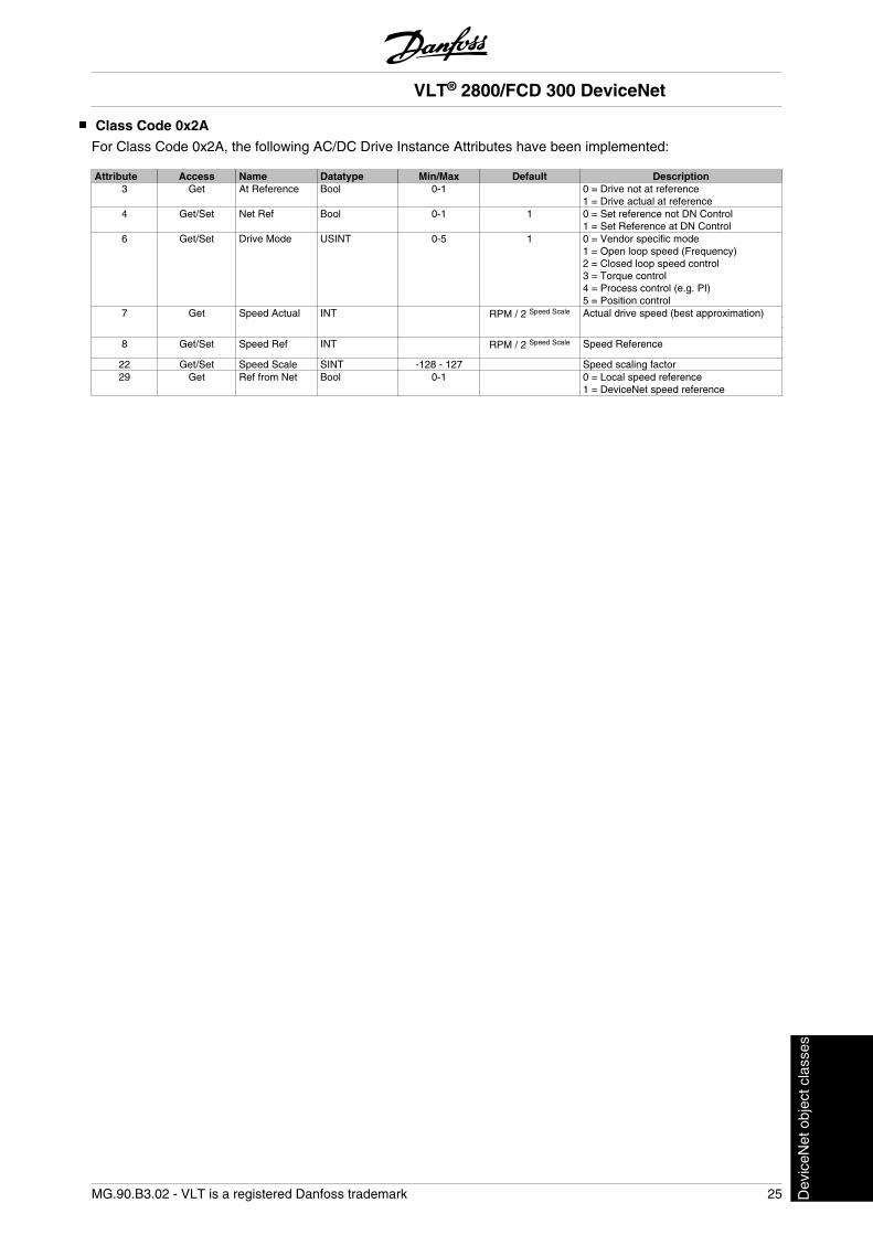
Class Code 0x2A
For Class Code 0x2A, the following AC/DC Drive Instance Attributes have been implemented:
Attribute Access Name Datatype Min/Max Default Description3 Get At Reference Bool 0-1 0 = Drive not at reference
1 = Drive actual at reference4 Get/Set Net Ref Bool 0-1 1 0 = Set reference not DN Control
1 = Set Reference at DN Control6 Get/Set Drive Mode USINT 0-5 1 0 = Vendor specific mode
1 = Open loop speed (Frequency)2 = Closed loop speed control3 = Torque control4 = Process control (e.g. PI)5 = Position control
7 Get Speed Actual INT RPM / 2 Speed Scale Actual drive speed (best approximation)
8 Get/Set Speed Ref INT RPM / 2 Speed Scale Speed Reference
22 Get/Set Speed Scale SINT -128 - 127 Speed scaling factor29 Get Ref from Net Bool 0-1 0 = Local speed reference
1 = DeviceNet speed reference
VLT® 2800/FCD 300 DeviceNet
MG.90.B3.02 - VLT is a registered Danfoss trademark 25 Dev
iceN
et o
bjec
t cla
sses
Danfoss Classes
Parameter 001 - 099 Class 100Parameter 101 - 199 Class 101Parameter 200 - 299 Class 102Parameter 300 - 399 Class 103Parameter 400 - 499 Class 104Parameter 500 - 599 Class 105Parameter 600 - 699 Class 106Parameter 700 - 799 Class 107Parameter 800 - 899 Class 108Parameter 900 - 999 Class 109Index Pointer Class 120
Instance Description:The Danfoss VLT 2800/FCD 300 DeviceNet only useInstance 1, so always leave this at the value of 1.
Attribute Description:The attributes for the VLT 2800/FCD 300 parameterare the last 2 (two) digits of the parameter + 100.
Example:The parameter 529 (Analog input, terminal 53) willhave the following:
Class 105Instance 1Attribute 129
Reading/writing to parameters with index:Parameters of type indexed (e.g. 915 & 916) needspecial handling since DeviceNet does not support in-dexed addressing.The way to handle this in the VLT 2800/FCD 300, is byusing the the Danfoss Class 120. which serves as anindex pointer. The pointer has to be set up before ev-ery read/write of an indexed parameter.
NB!If two masters are accessing this featureat the same ime, wrong data may occur.
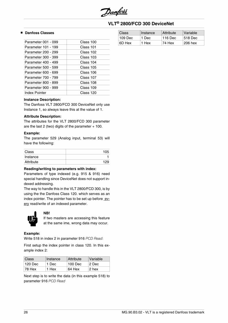
Example:Write 518 in index 2 in parameter 916 PCD Read:
First setup the index pointer in class 120. In this ex-ample index 2:
Class Instance Attribute Variable120 Dec 1 Dec 100 Dec 2 Dec78 Hex 1 Hex 64 Hex 2 hex
Next step is to write the data (in this example 518) toparameter 916 PCD Read
Class Instance Attribute Variable109 Dec 1 Dec 116 Dec 518 Dec6D Hex 1 Hex 74 Hex 206 hex
VLT® 2800/FCD 300 DeviceNet
26 MG.90.B3.02 - VLT is a registered Danfoss trademark
DeviceNet Operation ModeBit Strobe
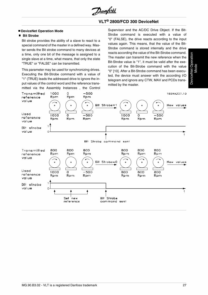
Bit strobe provides the ability of a slave to react to aspecial command of the master in a defined way. Mas-ter sends the Bit strobe command to many devices ata time, only one bit of the message is assigned to asingle slave at a time, what means, that only the state"TRUE" or "FALSE" can be transmitted.
This parameter may be used for synchronizing drives.Executing the Bit-Strobe command with a value of"1" (TRUE) leads the addressed drive to ignore the in-put values of the control word and the reference trans-mitted via the Assembly Instances , the Control
Supervisor and the AC/DC Drive Object. If the Bit-Strobe command is executed with a value of"0" (FALSE), the drive reacts according to the inputvalues again. This means, that the value of the Bit-Strobe command is stored internally and the drivereacts according the value of the Bit-Strobe command.The master can transmit the new reference when theBit-Strobe value is "1", it must be valid after the exe-cution of the Bit-Strobe command with the value"0" [10]. After a Bit-Strobe command has been execu-ted, the device must answer with the according I/Otelegram and ignore any CTW, MAV and PCDs trans-mitted by the master.
VLT® 2800/FCD 300 DeviceNet
MG.90.B3.02 - VLT is a registered Danfoss trademark 27
Dev
iceN
et O
pera
tion
Mod
e
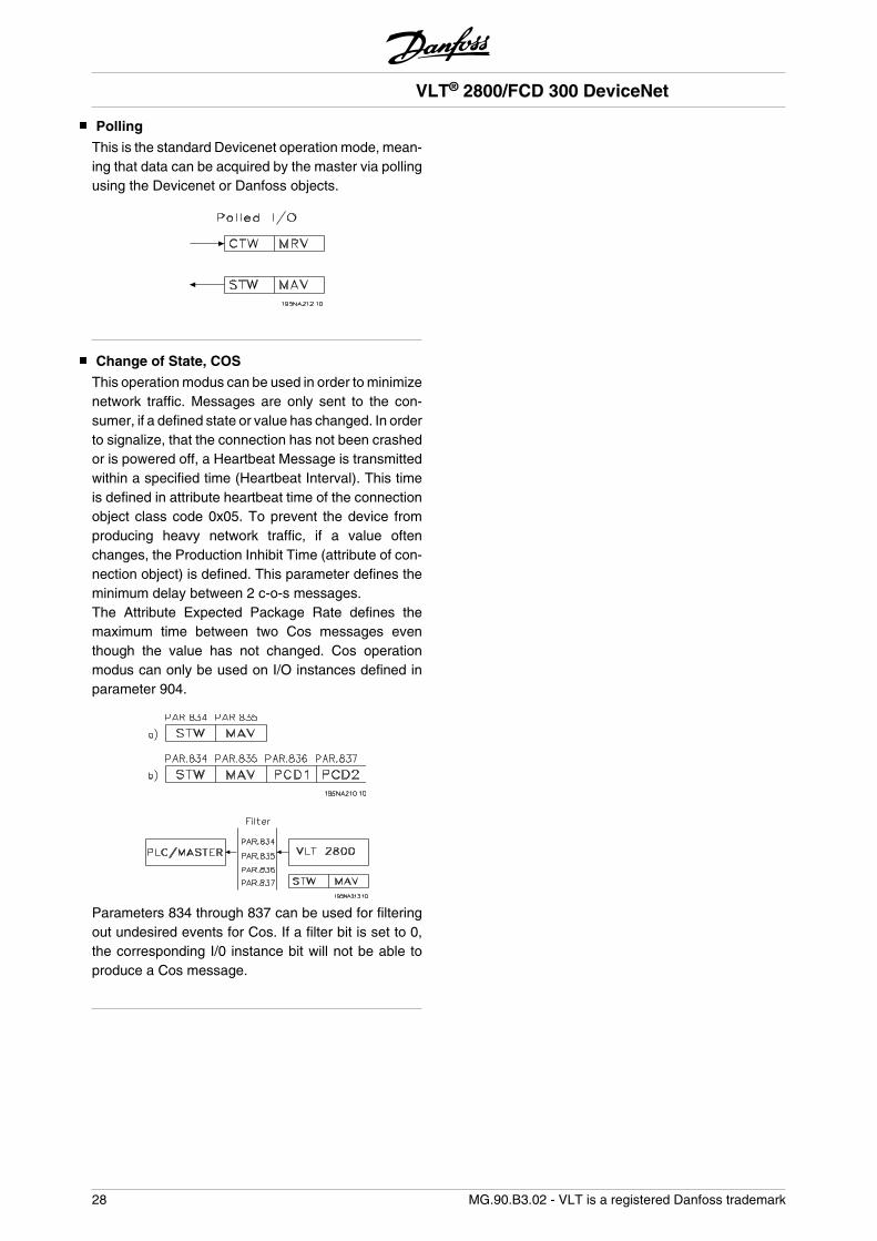
Polling
This is the standard Devicenet operation mode, mean-ing that data can be acquired by the master via pollingusing the Devicenet or Danfoss objects.
Change of State, COS
This operation modus can be used in order to minimizenetwork traffic. Messages are only sent to the con-sumer, if a defined state or value has changed. In orderto signalize, that the connection has not been crashedor is powered off, a Heartbeat Message is transmittedwithin a specified time (Heartbeat Interval). This timeis defined in attribute heartbeat time of the connectionobject class code 0x05. To prevent the device fromproducing heavy network traffic, if a value oftenchanges, the Production Inhibit Time (attribute of con-nection object) is defined. This parameter defines theminimum delay between 2 c-o-s messages.The Attribute Expected Package Rate defines themaximum time between two Cos messages eventhough the value has not changed. Cos operationmodus can only be used on I/O instances defined inparameter 904.
Parameters 834 through 837 can be used for filteringout undesired events for Cos. If a filter bit is set to 0,the corresponding I/0 instance bit will not be able toproduce a Cos message.
VLT® 2800/FCD 300 DeviceNet
28 MG.90.B3.02 - VLT is a registered Danfoss trademark
EDS FilesNote that the EDS files can be uploaded from the VLTfrequency converters via RS Networx. Before upload-ing the EDS file you must check the version of RSNetworx in Help and About RS Networx. RS Networxversion 3.11.00 supports the format Errata 2 and nochanges must be made to the VLT frequency convert-er. RS Networx version 3.00.00 supports Errata 1 andparameter 838 EDS Data type must be set to Errata 1and power must be re-cycle.
Start RS Networx and go online and the VLT 2800/FCD 300 will be shown as a grey box as unregistereddevice. Click on the VLT 2800/FCD 300 and go toTools and choose EDS Wizard. Click on next by theEDS wizard and choose Create an EDS file. RS Net-worx will now start to create an EDS file from the VLTfrequency converter.To upload EDS files please visitwww.DanfossDrives.com
VLT 2800 US version with DeviceNetProduct Code Drive Model Drive Rating
kW (HP)Voltage EDS File Name
232 VLT 2803 0.37 (0.50) 200 - 240 V 233 VLT 2805 0.55 (0.75) 200 - 240 V 234 VLT 2807 0.75 (1.00) 200 - 240 V 235 VLT 2811 1.10 (1.50) 200 - 240 V 236 VLT 2815 1.50 (2.00) 200 - 240 V 237 VLT 2822 2.20 (3.00) 200 - 240 V 238 VLT 2830 3.70 (5.00) 200 - 240 V 283 VLT 2805 0.55 (0.75) 380 - 480 V 284 VLT 2807 0.75 (1.00) 380 - 480 V 285 VLT 2811 1.10 (1.50) 380 - 480 V 286 VLT 2815 1.50 (2.00) 380 - 480 V 287 VLT 2822 2.20 (3.00) 380 - 480 V 288 VLT 2830 3.00 (4.00) 380 - 480 V 289 VLT 2840 4.00 (5.00) 380 - 480 V 290 VLT 2855 5.50 (7.50) 380 - 480 V 291 VLT 2875 7.50 (10.00) 380 - 480 V 292 VLT 2880 11.0 (15.00) 380 - 480 V 293 VLT 2881 15.0 (20.00) 380 - 480 V 294 VLT 2882 18.5 (25.00) 380 - 480 V
VLT 2800 European version with DeviceNetProduct Code Drive Model Drive Rating
kW (HPVoltage EDS File Name
332 VLT 2803 0.37 (0.50) 200 - 240 V 333 VLT 2805 0.55 (0.75) 200 - 240 V 334 VLT 2807 0.75 (1.00) 200 - 240 V 335 VLT 2811 1.10 (1.50) 200 - 240 V 336 VLT 2815 1.50 (2.00) 200 - 240 V 337 VLT 2822 2.20 (3.00) 200 - 240 V 338 VLT 2830 3.70 (5.00) 200 - 240 V 383 VLT 2805 0.55 (0.75) 380 - 480 V 384 VLT 2807 0.75 (1.00) 380 - 480 V 385 VLT 2811 1.10 (1.50) 380 - 480 V 386 VLT 2815 1.50 (2.00) 380 - 480 V 387 VLT 2822 2.20 (3.00) 380 - 480 V 388 VLT 2830 3.00 (4.00) 380 - 480 V 389 VLT 2840 4.00 (5.00) 380 - 480 V 390 VLT 2855 5.50 (7.50) 380 - 480 V 391 VLT 2875 7.50 (10.00) 380 - 480 V 392 VLT 2880 11.0 (15.00) 380 - 480 V 393 VLT 2881 15.0 (20.00) 380 - 480 V 394 VLT 2882 18.5 (25.00) 380 - 480 V
FCD 300 European version with DeviceNetProduct Code Drive Model Drive Rating
kW (HPVoltage EDS File Name
480 FCD 303 0.37 (0.50) 380 - 480 V 481 FCD 305 0.55 (0.75) 380 - 480 V 482 FCD 307 0.75 (1.00) 380 - 480 V 483 FCD 311 1.10 (1.50) 380 - 480 V 484 FCD 315 1.50 (2.00) 380 - 480 V 485 FCD 322 2.20 (3.00) 380 - 480 V 486 FCD 330 3.00 (4.00) 380 - 480 V
VLT® 2800/FCD 300 DeviceNet
MG.90.B3.02 - VLT is a registered Danfoss trademark 29
ED
S F
iles
Special Attention
NB!Please note, that terminal 46 has been re-moved from the VLT 2800 DeviceNetcard, meaning that parameter 341 - 342are not having any function.
• 002:
If operation site = Local, then control via DeviceNet isnot possible.
• 502-508:
Selection of how to gate DeviceNet control commandswith control commands on the digital inputs of the con-trol card.
• 515-538:
Data read out parameters that can be used to readvarious actual data from the VLT, as for example ac-tual status on the analog and digital inputs of thecontrol card thus using these as inputs to the master.
• 800 Protocol Select
Select DeviceNet in this parameter.• 801 Baud rate select
Selection of DeviceNet transmission speed.• 833 Fieldbus enable
Enable the DeviceNet communication. The defaultsetting is disable.
• 904 PPO selection
Selection of Instance type.• 918 Station address / MAC ID
Set the Station address / MAC ID in this parameter.
620 Operation Mode
(OPERATION MODE)
Value:
Normal operation (NORMAL OPERATION) [0]
Control card test (CONTROL CARD TEST) [2]
Initialize (INITIALIZE) [3]
Function:In addition to its normal function, this parameter canbe used to test the control card.There is also the opportunity to perform an initialisationat the factory setting for all parameters in all Setups,with the exception of parameters 500 Address, 501Baudrate, 600-605 Operating data and 615-617 Faultlog.
Description of choice:For FCD 300 connections see FCD 300 Design GuideMG.04.AX.YY par. 620.
Normal function [0] is used for normal operation of themotor.
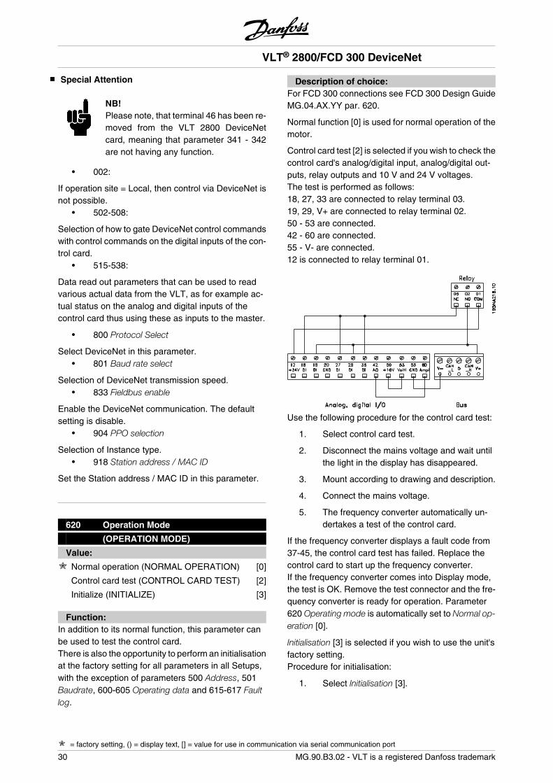
Control card test [2] is selected if you wish to check thecontrol card's analog/digital input, analog/digital out-puts, relay outputs and 10 V and 24 V voltages.The test is performed as follows:18, 27, 33 are connected to relay terminal 03.19, 29, V+ are connected to relay terminal 02.50 - 53 are connected.42 - 60 are connected.55 - V- are connected.12 is connected to relay terminal 01.
Use the following procedure for the control card test:
1. Select control card test.
2. Disconnect the mains voltage and wait untilthe light in the display has disappeared.
3. Mount according to drawing and description.
4. Connect the mains voltage.
5. The frequency converter automatically un-dertakes a test of the control card.
If the frequency converter displays a fault code from37-45, the control card test has failed. Replace thecontrol card to start up the frequency converter.If the frequency converter comes into Display mode,the test is OK. Remove the test connector and the fre-quency converter is ready for operation. Parameter620 Operating mode is automatically set to Normal op-eration [0].
Initialisation [3] is selected if you wish to use the unit'sfactory setting.Procedure for initialisation:
1. Select Initialisation [3].
VLT® 2800/FCD 300 DeviceNet
= factory setting, () = display text, [] = value for use in communication via serial communication port
30 MG.90.B3.02 - VLT is a registered Danfoss trademark
2. Disconnect the mains voltage and wait untilthe light in the display has disappeared.
3. Connect the mains voltage.
4. An initialisation is performed in all parame-ters in all Setups, with the exception of pa-rameters 500 Address, 501 Baudrate,600-605 Operating data, 615-617 Fault log,833 Fieldbus enable and 904 PPO selection.
800 Protocol Select
(Protocol Select)
Value:
DeviceNet (DeviceNet) [2]
Function:This parameter is read only.
801 Baud Rate Select
(Baud Rate Select)
Value:
125 kbps (125 kbps) [20]
250 kbps (250 kbps) [21]
500 kbps (500 kbps) [22]
Function:Selection of the DeviceNet transmission speed. It mustcorrespond to the transmission speed of the masterand the other DeviceNet nodes.
Description of choice:Select the baud rate.
NB!Note that a change of this parameter isfirst executed at next power up.
803 Bus time out
(bus time out)
Value:1 - 99 sec 1 sec
Function:If the VLT frequency converter doesn't receive a con-trol word for a period longer than the time set in this
parameter, the function selected in parameter 804 Re-sponse after bus errror will be activated.
Description of choice:Set the desired time.
Please note, that when the drive is running Cyclic orCOS mode, the Bus time out has to be set higher thanHeartbeat Rate. If not, the VLT will time out.
804 Bus time out function
(time out funct.)
Value:
OFF (off) [0]
Freeze output frequency (freeze output) [1]
Stop with auto restart (stop) [2]
Output = jog frequency (jogging) [3]
Output = max speed (max speed) [4]
Stop with trip (stop and trip) [5]
Select Setup 2 (select setup 2) [8]
Function:The timeout counter is activated at the first receipt ofa valid control word, i.e. bit 10 = OK.
Description of choice:The VLT remains in the timeout status until one of thefollowing four conditions occurs.
1. A valid control word (bit 10 = OK) is receivedand control via DeviceNet is resumed withthe current control word. If the timeout func-tion Stop with trip is selected a reset via bus,terminals or control panel is necessary.
2. Parameter 002 = Local operation => localcontrol through control panel is active.
3. Parameter 804 = Off => control via DeviceNetis resumed, with the control word used lastbeing taken.
805 Bit 10 function
(bit 10 function)
Function:This parameter is read only.
VLT® 2800/FCD 300 DeviceNet
= factory setting, () = display text, [] = value for use in communication via serial communication port
MG.90.B3.02 - VLT is a registered Danfoss trademark 31
Pro
gram
min
g
832 Bus Off Interrupt Behavior
(bus off int. beh)
Value:
Hold the device in bus-off state (HOLD CAN) [0]
Reset the device and continue communicating(RESET CAN) [1]
Function:This parameter defines the VLT 2800/FCD 300 be-havior if a bus-off interrupt is detected.
Description of choice:If this parameter is set to Hold the device in bus-offstate [0] and a bus-off event is detected, the VLT 2800/FCD 300 will go into reset/bus-off state.
If this parameter is set to Reset the device and continuecommunicating [1] and a bus-off event is detected theVLT 2800/FCD 300 will try to reset and re-initialise theCAN chip and to continue communication.
833 Fieldbus enable
(Fieldbus enable)
Value:
Disabled (disable) [0]
Enabled (enable) [1]
Function:This parameter allows to disable the communicationinterface.
Description of choice:Select Enable [1] to start the DeviceNet communica-tion.
If Disable [0] is selected no communication warning willappear, since the communication interface is disabled.
NB!Note that a change of this parameter isfirst executed at next power up.
834 Filter Mask for status word
(Cos Filter 1)
Value:0000 - FFFF Hex 0000 Hex
Function:When operating in COS (Change-Of-State) it is pos-sible to filter out bits in the status word that should notbe send if they changes.
Description of choice:Setup the filter mask for the status word.
NB!For further information, see the sectionChange of state, Cos.
835 Filter Mask for main actual value
(Cos Filter 2)
Value:0000 - FFFF Hex 0000 Hex
Function:When operating in COS (Change-Of-State) it is pos-sible to filter out bits in the Main actual value thatshould not be send if they changes.
Description of choice:Setup the filter mask for the Main actual value.
836 Filter Mask PCD 1
(Cos Filter 3)
Value:0000 - FFFF Hex 0000 Hex
Function:When operating in COS (Change-Of-State) it is pos-sible to filter out bits in PCD 1 that should not be sendif they changes.
Description of choice:Setup the filter mask for PCD 1.
837 Filter Mask PCD 2
(Cos Filter 4)
Value:0000 - FFFF Hex 0000 Hex
Function:When operating in COS (Change-Of-State) it is pos-sible to filter out bits in PCD 2 that should not be sendif they changes.
VLT® 2800/FCD 300 DeviceNet
= factory setting, () = display text, [] = value for use in communication via serial communication port
32 MG.90.B3.02 - VLT is a registered Danfoss trademark
Description of choice:Setup the filter mask for PCD 2.
838 EDS Data Types
(EDS Data Types)
Value:
Errata 1 (errata 1) [0]
Errata 2 (Errata 2) [1]
Function:In this parameter it is possible to select between twodata types when uploading an EDS file from the VLTfrequency converter. The current versions of the con-figuration tools like DeviceNet Manager and RS Net-worx can only handle data type Errata 1.
Description of choice:Select Errata 1 if DeviceNet Manager or RS Networxversion 3.00 is used.Select Errata 2 if DeviceNet Manager or RS Networxversion 3.11 or higher is used.
839 EDS Product code
(EDS Product code)
Value:
Power dependent [0]
Power independent [1]
Function:In this parameter it is possible to set the VLT 2800/FCD300 to one Product code.
Description of choice:Power dependent: The Product code in each powerrange is different as shown in the section EDS Files.Power independent: The Product code in each powerrange is the same and only one EDS file can be used.Note that by this choice the EDS file cannot be uploa-ded from the Drive. The Power independent EDS fileis available on www.danfoss.com/drives.
850 Readout Transmit Error Counter
(R.out.tr.err.co.)
Function:This parameter is a read out of the Transmit ErrorCounterof the CAN controller since the last power up.
851 Readout Receive Error Counter
(r.out.re.err.co.)
Function:This parameter is a read out of the Receive Error Coun-ter of the CAN controller since the last power up.
852 Readout Bus Off Counter
(r.out.bus.off.co)
Function:This parameter is a read out of the how many Bus Offevents there has been since the last power up.
860 Controlword
(Controlword)
Function:This parameter is a read out of the VLT frequencyControl word. This parameter can only be read viastandard bus or DeviceNet and is not available viaLCP.
861 Reference Value
(Reference Value)
Function:This parameter is a read out of the VLT frequency Re-fence value in the range 0 - 4000 Hex. This parametercan only be read via standard bus or DeviceNet and isnot available via LCP.
880 Statusword
(Statusword)
Function:This parameter is a read out of the VLT frequency Sta-tus word. This parameter can only be read via standardbus or DeviceNet and is not available via LCP.
881 Main Actual Value
(Main Actual Val.)
Function:This parameter is a read out of the VLT frequency MainActual Value in the range of 0 - 4000 Hex. This pa-
VLT® 2800/FCD 300 DeviceNet
= factory setting, () = display text, [] = value for use in communication via serial communication port
MG.90.B3.02 - VLT is a registered Danfoss trademark 33
Pro
gram
min
g
rameter can only be read via standard bus or Device-Net and is not available via LCP.
VLT® 2800/FCD 300 DeviceNet
34 MG.90.B3.02 - VLT is a registered Danfoss trademark
904 PPO selection
(ppo type select)
Value:
Instance 20/70 (INSTANCE 20/70) [10]
Instance 21/71 (INSTANCE 21/71) [11]
Instance 100/150 (Instance 100/150) [12]
Instance 101/151 (INSTANCE 101/151) [13]
Function:This parameter allows to select between four differentinstances for the data transmission.Instances 100/150 and 101/151 is a Danfoss specificinstance and instance 20/70 and 21/71 is a ODVAspecific AC Drive profile.See also Drive profile in this manual for further infor-mation.
NB!Note that a change of this parameter isfirst executed at next power up.
Description of choice:Instance 100/150 use 2 words - one word for the con-trol word and one word for the reference. See thecontrol word in Control word and Status word underinstance 100/150 in this manual.
Instance 101/151 use 4 words - one word for the con-trol word and one word for the reference. The last twowords (PCD1 and PCD2) are user definable where itis possible to read and write to parameters via I/Ocommunication. By using PCD to read data from pa-rameters in the VLT it will be must quicker update thanexplicit message.See the control word in Control word and Status wordunder instance 100/150 in this manual
Instance 20/70 use 2 words - one word for the controlword and one word for the reference. See the controlword in Control word and Status word under instance20/70 in this manual.
Instance 21/71 use 2 words - one word for the controlword and one word for the reference. See the controlword in Control word and Status word under instance21/71 in this manual.
NB!Note that AC Drive profile is only availableif selecting Instance 20/70 or 21/71.
915 PCD write configuration
(pcd config write)
Value:
Sub index 1 (PCD 1) [Parameter number]
Sub index 2 (PCD 2) [Parameter number]
Function:Different parameters can be assigned to PCD 1-2 ifinstance 101/151 is selected in parameter 904 PPOSelection. The values in PCD 1-2 will be written to theselected parameters in the form of data values.
Description of choice:The sequence of the subindixes corresponds to thesequence of the PCD in the PPO, i.e. subindex 1 =PCD 1, subindex 2 = PCD 2 etc. Each subindex maycontain the number of any VLT parameter.
Note that subindex 3 - 8 are having no function.
916 PCD read configuration
(pcd config read)
Value:
Sub index 1 (PCD 1) [Parameter number]
Sub index 2 (PCD 2) [Parameter number]
Function:Different parameters can be assigned to PCD 1-2 ifinstance 101/151 is selected in parameter 904 PPOSelection. The values in PCD 1-2 will be read from theselected parameters in the form of data values.
Description of choice:The sequence of subindices corresponds to the se-quence of the PCD in the PPO, i.e.subindex 1 = PCD1, subindex 2 = PCD 2 etc. Each subindex may containthe number of any VLT parameter.
Note that subindex 3 - 8 are having no function.
918 Station address/MAC ID
(station address)
Value:0 - 63 63
Function:Every station connected to the same DeviceNet net-work must have an unambiguous address.
VLT® 2800/FCD 300 DeviceNet
= factory setting, () = display text, [] = value for use in communication via serial communication port
MG.90.B3.02 - VLT is a registered Danfoss trademark 35
Pro
gram
min
g
Description of choice:Set a unique address for each VLT 2800/FCD 300 thatare connected to the same DeviceNet network.
NB!Note that a change of this parameter isfirst executed at next power up.
953 Warning messages
(warning param.)
Value:0 - FFFF Hex
Function:In this parameter it is possible to read out warningmessages via standard bus or DeviceNet. This pa-rameter is not available via LCP, but the warning mes-sage can be seen by choosing Com warning word asdisplay readout.A bit is assigned to every warning (see the followinglist).
Bit Status0 Bus not active (only if the bus has
been active for at least once sincelast power-up)
1 Explicit connection timeout2 I/O connection timeout3 Error Passive Receive4 Error Warning Receive5 CAN bus off6 I/O send error7 Initialisation error8 No bus supply9 Bus reset10 Error Passive Transmit11 Error warning Transmit12 Duplicate MAC ID Error13 RX queue overrun14 TX queue overrun15 CAN overrun
Bus not active: means, that no bus communication ispresent or that the slave is not allocated.
Explicit connection timeout: This bit is set, if an explicitconnection is timed out.
I/O connection timeout: This bit is set, if an I/O con-nection is timed out.
Error Passive Receive: This bit is set, if the CAN con-troller has reached it’s error passive state for the mes-sage receiver.
Error Warning Receive: This bit is set, if the CAN con-troller has reached it’s error warning state (more then96 receive errors) for the message receiver.
CAN bus off: This bit is set, if CAN bus has beenswitched off, because a receive or Transmission ErrorCounter exceed a value of 255 or a bus off interrupthas occurred.
I/O send error: This bit is set, if an I/O send error hasbeen detected.
Initialisation error: This bit is set, if the CAN controllerhas failed to initialize.
No bus supply: This bit is set, if the DN bus supply(normally 24 V) is not available. Only set, if DN optionis active, and not, if CanOpen is active.
Bus reset: This bit is set, if the DN communication hasbeen reset.
Error Passive Transmit: This bit is set, if the bus stateerror passive for the transmitter is reached. Please re-fer to chapter 5.8.
Error warning Transmit: This bit is set, if transmit errorcounter exceeds a value of 96, signalizing that the busmay be seriously damaged.
Duplicate MAC ID Error: This bit is set, if duplicateMAC ID has been detected.
RX queue overrun: This bit is set, if receive data bufferhas been overrun.
TX queue overrun: This bit is set, if transmit data bufferhas been overrun
CAN overrun: This bit is set, if CAN data buffer hasbeen overrun.
967 Control Word
(control word)
Value:16 bit binary code
Function:Parameter 967 is dedicated to sending a control wordto the VLT frequency converter when using explicitmessage. This parameter is not available via LCP.
968 Status Word
(status word)
Value:Read only (16 bit binary code)
VLT® 2800/FCD 300 DeviceNet
= factory setting, () = display text, [] = value for use in communication via serial communication port
36 MG.90.B3.02 - VLT is a registered Danfoss trademark
Function:Parameter 968 is dedicated to read the status wordfrom the VLT frequency converter when using explicitmessage. This parameter is not available via LCP.
970 Parameter setup selection
(edit setup select)
Value:
Factory setting [0]
Parameter setup 1 (setup 1) [1]
Parameter setup 2 (setup 2) [2]
Parameter setup 3 (setup 3) [3]
Parameter setup 4 (setup 4) [4]
Active set up (active setup) [5]
Function:Like parameter 005 (described in the product manualfor the VLT 2800 series).
Description of choice:It is only possible to write to the active set-up via De-viceNet in the VLT 2800/FCD 300. This means that itis not possible to run for instance in set-up 1 andchange data in set-up 2, 3 or 4.
971 Save date values
(store data value)
Value:
Not active (off) [0]
Save active setup (store active setup) [1]
Save edit setup (store edit setup) [2]
Save all setups (store all setups) [3]
Store always (store always) [4]
Function:Parameter values modified through DeviceNet are on-ly saved in RAM, i.e. the modifications are lost in theevent of a power failure. This parameter is used to ac-tivate a function by means of which all parametervalues are saved in EEPROM, preserving them evenin the case of a power failure.
Description of choice:
- Not active: The function is not active.
- Save active setup: All parameter setups of theactive setup are saved in EEPROM. The val-
ue returns to Not active after all parametervalues have been saved.
- Save edit setup: All parameter setups of thesetup being processed are saved in EE-PROM. The value returns to Not active afterall parameter values have been saved.
- Save all setups: All parameter setups in allsetups are saved in EEPROM. The value re-turns to Not active after all parameter valueshave been saved.
- Store always: Each parameter write requestwill automatically be stored in EEPROM.
NB!Please note that continous writing via ex-plicit message may damage the EE-PROM.
980–982 Defined parameters
(defined param.)
Value:Read only
Function:The three parameters contain a list of all parametersdefined in the VLT. Each of the three parameters canbe read as an array by means of a explicit message.
Each parameter contains up to 116 elements (param-eter numbers). The number of parameters that are inuse (980, 981 and 982) depends on the respective VLTconfiguration.
When a 0 is issued as a parameter number, the listends.
990–992 Modified parameters
(modifi. param.)
Value:Read only
Function:The three parameters contain a list of all parametersthat have been changed from the factory setting. Everyone of the three parameters can be read as an arraywith the help of the explicit read service. The subindi-ces begin with 1 and follow the sequence of the pa-rameter numbers. Each parameter contains up to 116elements (parameter numbers). The number of pa-
VLT® 2800/FCD 300 DeviceNet
= factory setting, () = display text, [] = value for use in communication via serial communication port
MG.90.B3.02 - VLT is a registered Danfoss trademark 37
Pro
gram
min
g
rameters that are in use (990, 991 and 992) dependson how many parameters have been modified in com-parison with the factory setting.
Pure read parameters (Read only), such as data out-put parameters, are not logged as modified even if theyare changing.
When a 0 is issued as a parameter number, the listends.
VLT® 2800/FCD 300 DeviceNet
38 MG.90.B3.02 - VLT is a registered Danfoss trademark
Warning and Alarm Messages
There is a clear distinction between alarms and warn-ings. In the case of an alarm, The VLT will enter a faultcondition. After the cause for the alarm has beencleared, the master will have to acknowledge the alarmmessage for the VLT to start operating again. A warn-ing on the other hand may come when a warningcondition appears, and disappear when conditions re-turn to normal without interfering with the process.
Warnings
Any warning within the VLT is represented by a singlebit within a warning word. A warning word is always anaction parameter. Bit status FALSE [0] means nowarning, while bit status TRUE [1] means warning. Toeach bit and each bit status there is a correspondingtext string. In addition to the warning word messagethe master will also be notified through a change of bit7 in the Status Word.
Alarms
Following an Alarm message the VLT will enter Faultcondition. Only after the fault has been alleviated andthe master has acknowledged the alarm message bysetting bit 3 in the Control Word, can the VLT resumeoperation. Any warning within the VLT is representedby a single bit within a warning word. A warning wordis always an action parameter. Bit status FALSE [0]means no fault, while bit status TRUE [1] means fault.To each bit and each bit status there is a correspond-ing text string.
VLT® 2800/FCD 300 DeviceNet
MG.90.B3.02 - VLT is a registered Danfoss trademark 39
Pro
gram
min
g
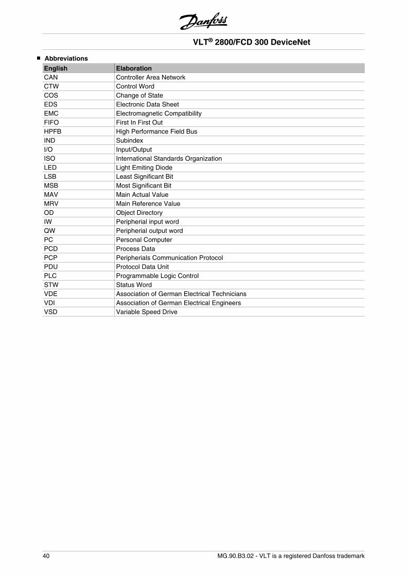
Abbreviations
English ElaborationCAN Controller Area NetworkCTW Control WordCOS Change of StateEDS Electronic Data SheetEMC Electromagnetic CompatibilityFIFO First In First OutHPFB High Performance Field BusIND SubindexI/O Input/OutputISO International Standards OrganizationLED Light Emiting DiodeLSB Least Significant BitMSB Most Significant BitMAV Main Actual ValueMRV Main Reference ValueOD Object DirectoryIW Peripherial input wordQW Peripherial output wordPC Personal ComputerPCD Process DataPCP Peripherials Communication ProtocolPDU Protocol Data UnitPLC Programmable Logic ControlSTW Status WordVDE Association of German Electrical TechniciansVDI Association of German Electrical EngineersVSD Variable Speed Drive
VLT® 2800/FCD 300 DeviceNet
40 MG.90.B3.02 - VLT is a registered Danfoss trademark
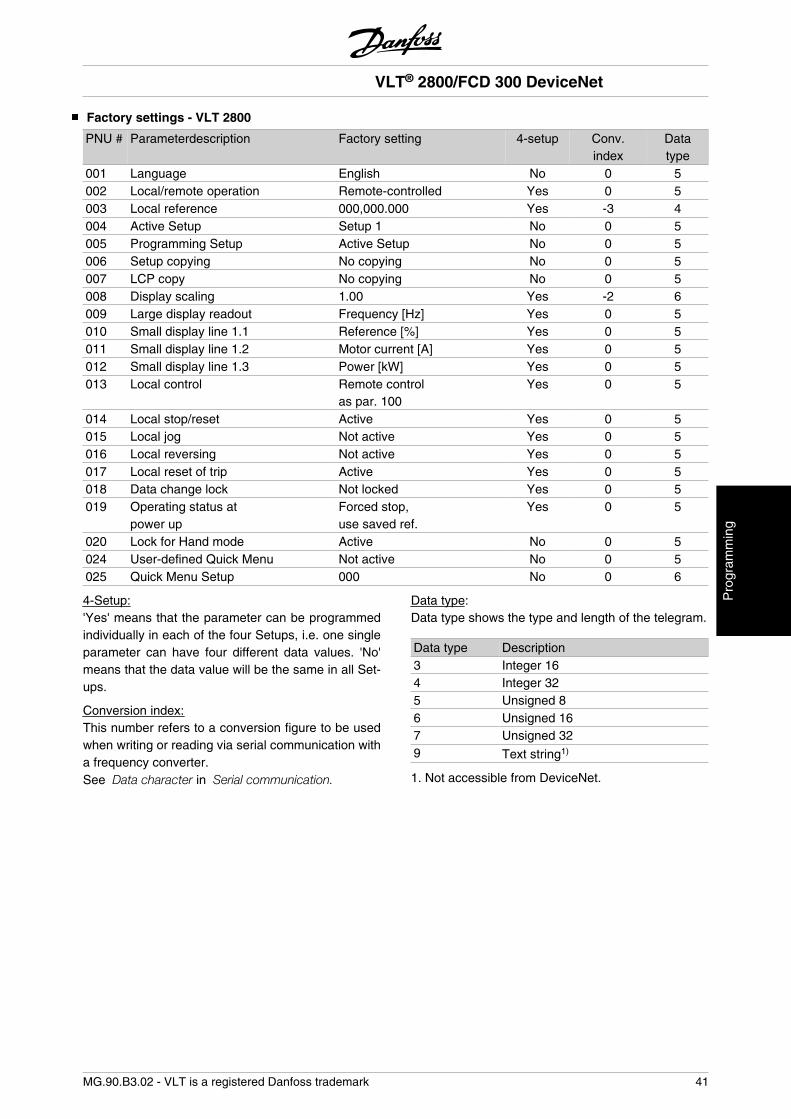
Factory settings - VLT 2800
PNU # Parameterdescription Factory setting 4-setup Conv.index
Datatype
001 Language English No 0 5002 Local/remote operation Remote-controlled Yes 0 5003 Local reference 000,000.000 Yes -3 4004 Active Setup Setup 1 No 0 5005 Programming Setup Active Setup No 0 5006 Setup copying No copying No 0 5007 LCP copy No copying No 0 5008 Display scaling 1.00 Yes -2 6009 Large display readout Frequency [Hz] Yes 0 5010 Small display line 1.1 Reference [%] Yes 0 5011 Small display line 1.2 Motor current [A] Yes 0 5012 Small display line 1.3 Power [kW] Yes 0 5013 Local control Remote control
as par. 100Yes 0 5
014 Local stop/reset Active Yes 0 5015 Local jog Not active Yes 0 5016 Local reversing Not active Yes 0 5017 Local reset of trip Active Yes 0 5018 Data change lock Not locked Yes 0 5019 Operating status at
power upForced stop,use saved ref.
Yes 0 5
020 Lock for Hand mode Active No 0 5024 User-defined Quick Menu Not active No 0 5025 Quick Menu Setup 000 No 0 6
4-Setup:'Yes' means that the parameter can be programmedindividually in each of the four Setups, i.e. one singleparameter can have four different data values. 'No'means that the data value will be the same in all Set-ups.
Conversion index:This number refers to a conversion figure to be usedwhen writing or reading via serial communication witha frequency converter.See Data character in Serial communication.
Data type:Data type shows the type and length of the telegram.
Data type Description3 Integer 164 Integer 325 Unsigned 86 Unsigned 167 Unsigned 329 Text string1)
1. Not accessible from DeviceNet.
VLT® 2800/FCD 300 DeviceNet
MG.90.B3.02 - VLT is a registered Danfoss trademark 41
Pro
gram
min
g
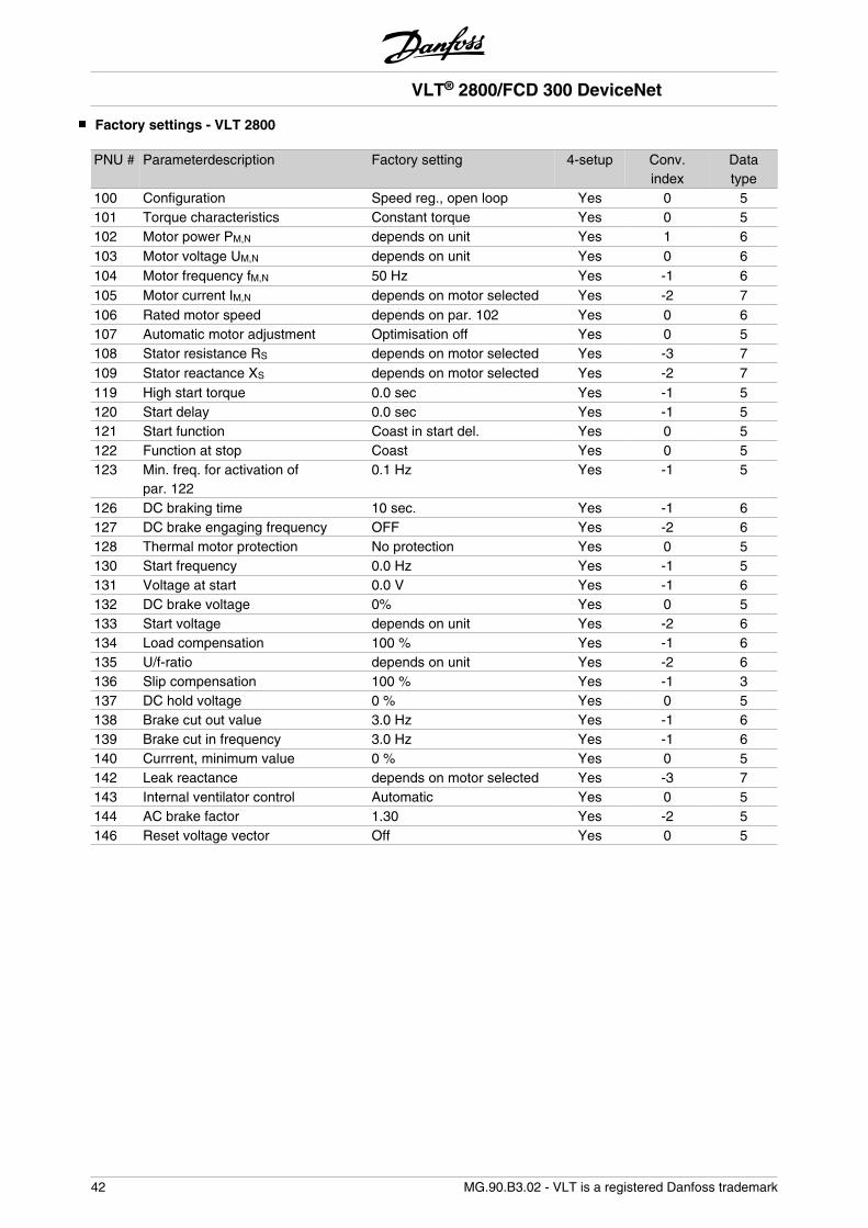
Factory settings - VLT 2800
PNU # Parameterdescription Factory setting 4-setup Conv.index
Datatype
100 Configuration Speed reg., open loop Yes 0 5101 Torque characteristics Constant torque Yes 0 5102 Motor power PM,N depends on unit Yes 1 6103 Motor voltage UM,N depends on unit Yes 0 6104 Motor frequency fM,N 50 Hz Yes -1 6105 Motor current IM,N depends on motor selected Yes -2 7106 Rated motor speed depends on par. 102 Yes 0 6107 Automatic motor adjustment Optimisation off Yes 0 5108 Stator resistance RS depends on motor selected Yes -3 7109 Stator reactance XS depends on motor selected Yes -2 7119 High start torque 0.0 sec Yes -1 5120 Start delay 0.0 sec Yes -1 5121 Start function Coast in start del. Yes 0 5122 Function at stop Coast Yes 0 5123 Min. freq. for activation of
par. 1220.1 Hz Yes -1 5
126 DC braking time 10 sec. Yes -1 6127 DC brake engaging frequency OFF Yes -2 6128 Thermal motor protection No protection Yes 0 5130 Start frequency 0.0 Hz Yes -1 5131 Voltage at start 0.0 V Yes -1 6132 DC brake voltage 0% Yes 0 5133 Start voltage depends on unit Yes -2 6134 Load compensation 100 % Yes -1 6135 U/f-ratio depends on unit Yes -2 6136 Slip compensation 100 % Yes -1 3137 DC hold voltage 0 % Yes 0 5138 Brake cut out value 3.0 Hz Yes -1 6139 Brake cut in frequency 3.0 Hz Yes -1 6140 Currrent, minimum value 0 % Yes 0 5142 Leak reactance depends on motor selected Yes -3 7143 Internal ventilator control Automatic Yes 0 5144 AC brake factor 1.30 Yes -2 5146 Reset voltage vector Off Yes 0 5
VLT® 2800/FCD 300 DeviceNet
42 MG.90.B3.02 - VLT is a registered Danfoss trademark
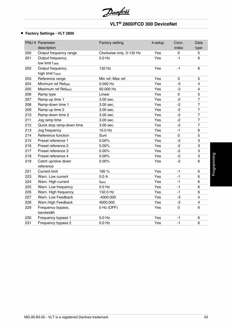
Factory Settings - VLT 2800
PNU # Parameterdescription
Factory setting 4-setup Conv.index
Datatype
200 Output frequency range Clockwise only, 0-132 Hz Yes 0 5201 Output frequency,
low limit f MIN
0.0 Hz Yes -1 6
202 Output frequency,high limit f MAX
132 Hz Yes -1 6
203 Reference range Min ref.-Max ref. Yes 0 5204 Minimum ref RefMIN 0.000 Hz Yes -3 4205 Maximum ref RefMAX 50.000 Hz Yes -3 4206 Ramp type Linear Yes 0 5207 Ramp-up time 1 3.00 sec. Yes -2 7208 Ramp-down time 1 3.00 sec. Yes -2 7209 Ramp-up time 2 3.00 sec. Yes -2 7210 Ramp-down time 2 3.00 sec. Yes -2 7211 Jog ramp time 3.00 sec. Yes -2 7212 Quick stop ramp-down time 3.00 sec. Yes -2 7213 Jog frequency 10.0 Hz Yes -1 6214 Reference function Sum Yes 0 5215 Preset reference 1 0.00% Yes -2 3216 Preset reference 2 0.00% Yes -2 3217 Preset reference 3 0.00% Yes -2 3218 Preset reference 4 0.00% Yes -2 3219 Catch up/slow down
reference0.00% Yes -2 6
221 Current limit 160 % Yes -1 6223 Warn. Low current 0.0 A Yes -1 6224 Warn. High current IMAX Yes -1 6225 Warn. Low frequency 0.0 Hz Yes -1 6226 Warn. High frequency 132.0 Hz Yes -1 6227 Warn. Low Feedback -4000.000 Yes -3 4228 Warn.High Feedback 4000.000 Yes -3 4229 Frequency bypass,
bandwidth0 Hz (OFF) Yes 0 6
230 Frequency bypass 1 0.0 Hz Yes -1 6231 Frequency bypass 2 0.0 Hz Yes -1 6
VLT® 2800/FCD 300 DeviceNet
MG.90.B3.02 - VLT is a registered Danfoss trademark 43
Pro
gram
min
g
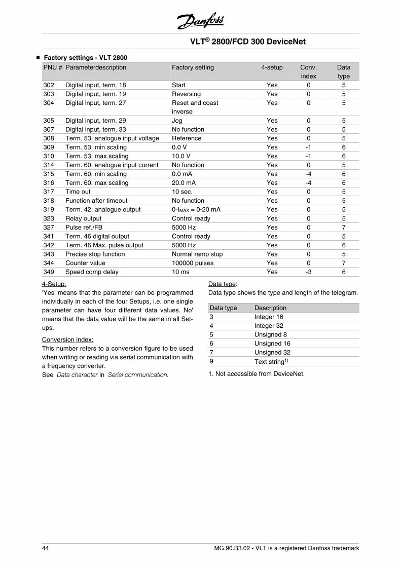
Factory settings - VLT 2800
PNU # Parameterdescription Factory setting 4-setup Conv.index
Datatype
302 Digital input, term. 18 Start Yes 0 5303 Digital input, term. 19 Reversing Yes 0 5304 Digital input, term. 27 Reset and coast
inverseYes 0 5
305 Digital input, term. 29 Jog Yes 0 5307 Digital input, term. 33 No function Yes 0 5308 Term. 53, analogue input voltage Reference Yes 0 5309 Term. 53, min scaling 0.0 V Yes -1 6310 Term. 53, max scaling 10.0 V Yes -1 6314 Term. 60, analogue input current No function Yes 0 5315 Term. 60, min scaling 0.0 mA Yes -4 6316 Term. 60, max scaling 20.0 mA Yes -4 6317 Time out 10 sec. Yes 0 5318 Function after timeout No function Yes 0 5319 Term. 42, analogue output 0-IMAX = 0-20 mA Yes 0 5323 Relay output Control ready Yes 0 5327 Pulse ref./FB 5000 Hz Yes 0 7341 Term. 46 digital output Control ready Yes 0 5342 Term. 46 Max. pulse output 5000 Hz Yes 0 6343 Precise stop function Normal ramp stop Yes 0 5344 Counter value 100000 pulses Yes 0 7349 Speed comp delay 10 ms Yes -3 6
4-Setup:'Yes' means that the parameter can be programmedindividually in each of the four Setups, i.e. one singleparameter can have four different data values. No'means that the data value will be the same in all Set-ups.
Conversion index:This number refers to a conversion figure to be usedwhen writing or reading via serial communication witha frequency converter.See Data character in Serial communication.
Data type:Data type shows the type and length of the telegram.
Data type Description3 Integer 164 Integer 325 Unsigned 86 Unsigned 167 Unsigned 329 Text string1)
1. Not accessible from DeviceNet.
VLT® 2800/FCD 300 DeviceNet
44 MG.90.B3.02 - VLT is a registered Danfoss trademark
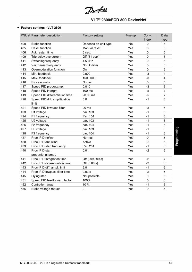
Factory settings - VLT 2800
PNU # Parameter description Factory setting 4-setup Conv.index
Datatype
400 Brake function Depends on unit type No 0 5405 Reset function Manual reset Yes 0 5406 Aut. restart time 5 sec. Yes 0 5409 Trip delay overcurrent Off (61 sec.) Yes 0 5411 Switching frequency 4.5 kHz Yes 0 6412 Var. carrier frequency No LC-filter Yes 0 5413 Overmodulation function On Yes 0 5414 Min. feedback 0.000 Yes -3 4415 Max. feedback 1500.000 Yes -3 4416 Process units No unit Yes 0 5417 Speed PID propor.ampl. 0.010 Yes -3 6418 Speed PID intergra. 100 ms Yes -5 7419 Speed PID differentiation time 20.00 ms Yes -5 7420 Speed PID diff. amplification
limit5.0 Yes -1 6
421 Speed PID lowpass filter 20 ms Yes -3 6423 U1 voltage par. 103 Yes -1 6424 F1 frequency Par. 104 Yes -1 6425 U2 voltage par. 103 Yes -1 6426 F2 frequency par. 104 Yes -1 6427 U3 voltage par. 103 Yes -1 6428 F3 frequency par. 104 Yes -1 6437 Proc. PID no/inv. Normal Yes 0 5438 Proc. PID anti wind. Active Yes 0 5439 Proc. PID start frequency Par. 201 Yes -1 6440 Proc. PID start
proportional ampl.0.01 Yes -2 6
441 Proc. PID integration time Off (9999.99 s) Yes -2 7442 Proc. PID differentiation time Off (0.00 s). Yes -2 6443 Proc. PID diff. ampl. limit 5.0 Yes -1 6444 Proc. PID lowpass filter time 0.02 s Yes -2 6445 Flying start Not possible Yes 0 5451 Speed PID feedforward factor 100% Yes 0 6452 Controller range 10 % Yes -1 6456 Brake voltage reduce 0 Yes 0 5
VLT® 2800/FCD 300 DeviceNet
MG.90.B3.02 - VLT is a registered Danfoss trademark 45
Pro
gram
min
g
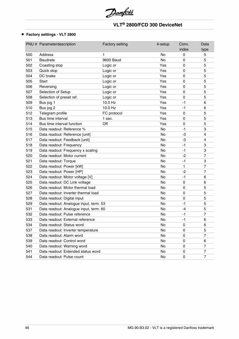
Factory settings - VLT 2800
PNU # Parameterdescription Factory setting 4-setup Conv.index
Datatype
500 Address 1 No 0 5501 Baudrate 9600 Baud No 0 5502 Coasting stop Logic or Yes 0 5503 Quick stop Logic or Yes 0 5504 DC brake Logic or Yes 0 5505 Start Logic or Yes 0 5506 Reversing Logic or Yes 0 5507 Selection of Setup Logic or Yes 0 5508 Selection of preset ref. Logic or Yes 0 5509 Bus jog 1 10.0 Hz Yes -1 6510 Bus jog 2 10.0 Hz Yes -1 6512 Telegram profile FC protocol Yes 0 5513 Bus time interval 1 sec. Yes 0 5514 Bus time interval function Off Yes 0 5515 Data readout: Reference % No -1 3516 Data readout: Reference [unit] No -3 4517 Data readout: Feedback [unit] No -3 4518 Data readout: Frequency No -1 3519 Data readout: Frequency x scaling No -1 3520 Data readout: Motor current No -2 7521 Data readout: Torque No -1 3522 Data readout: Power [kW] No 1 7523 Data readout: Power [HP] No -2 7524 Data readout: Motor voltage [V] No -1 6525 Data readout: DC Link voltage No 0 6526 Data readout: Motor thermal load No 0 5527 Data readout: Inverter thermal load No 0 5528 Data readout: Digital input No 0 5529 Data readout: Analogue input, term. 53 No -1 5531 Data readout: Analogue input, term. 60 No -4 5532 Data readout: Pulse reference No -1 7533 Data readout: External reference No -1 6534 Data readout: Status word No 0 6537 Data readout: Inverter temperature No 0 5538 Data readout: Alarm word No 0 7539 Data readout: Control word No 0 6540 Data readout: Warning word No 0 7541 Data readout: Extended status word No 0 7544 Data readout: Pulse count No 0 7
VLT® 2800/FCD 300 DeviceNet
46 MG.90.B3.02 - VLT is a registered Danfoss trademark
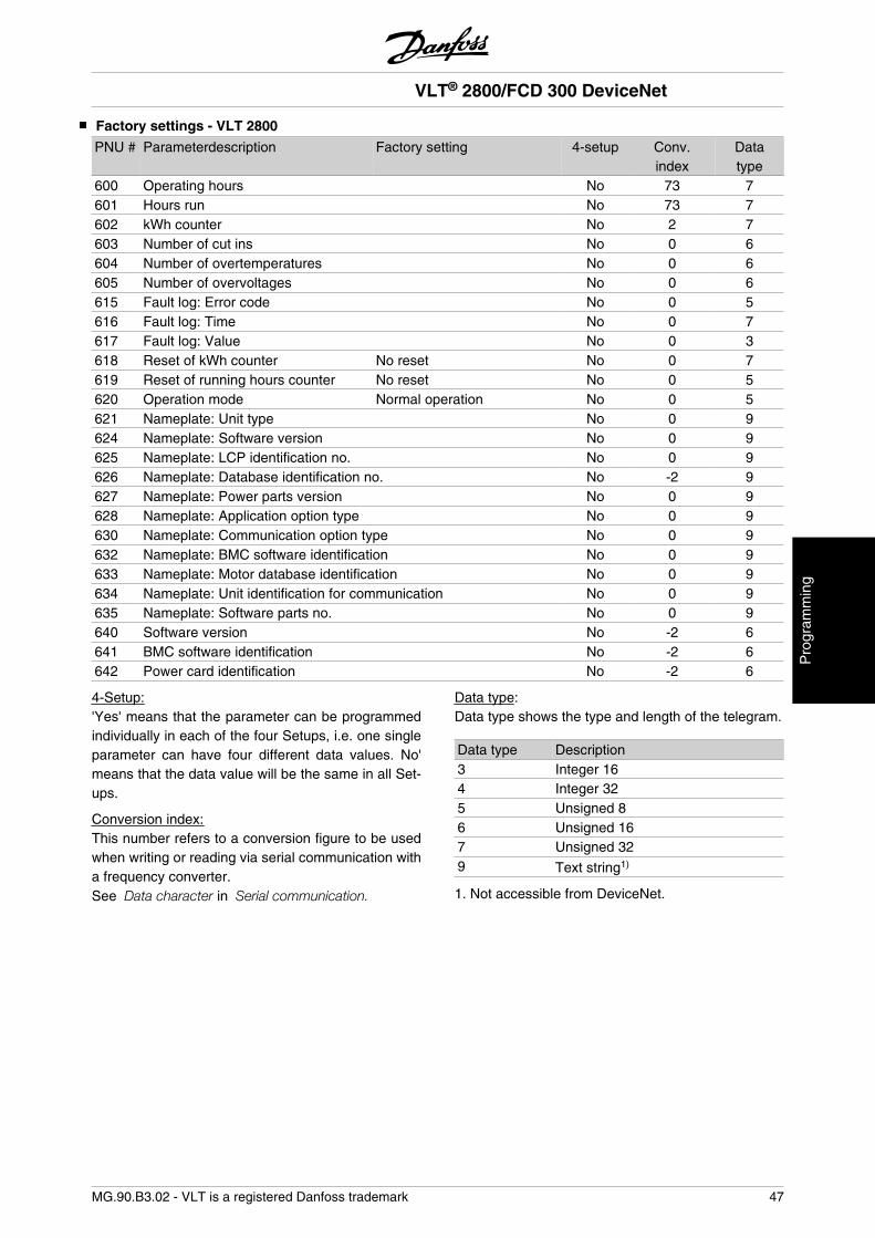
Factory settings - VLT 2800
PNU # Parameterdescription Factory setting 4-setup Conv.index
Datatype
600 Operating hours No 73 7601 Hours run No 73 7602 kWh counter No 2 7603 Number of cut ins No 0 6604 Number of overtemperatures No 0 6605 Number of overvoltages No 0 6615 Fault log: Error code No 0 5616 Fault log: Time No 0 7617 Fault log: Value No 0 3618 Reset of kWh counter No reset No 0 7619 Reset of running hours counter No reset No 0 5620 Operation mode Normal operation No 0 5621 Nameplate: Unit type No 0 9624 Nameplate: Software version No 0 9625 Nameplate: LCP identification no. No 0 9626 Nameplate: Database identification no. No -2 9627 Nameplate: Power parts version No 0 9628 Nameplate: Application option type No 0 9630 Nameplate: Communication option type No 0 9632 Nameplate: BMC software identification No 0 9633 Nameplate: Motor database identification No 0 9634 Nameplate: Unit identification for communication No 0 9635 Nameplate: Software parts no. No 0 9640 Software version No -2 6641 BMC software identification No -2 6642 Power card identification No -2 6
4-Setup:'Yes' means that the parameter can be programmedindividually in each of the four Setups, i.e. one singleparameter can have four different data values. No'means that the data value will be the same in all Set-ups.
Conversion index:This number refers to a conversion figure to be usedwhen writing or reading via serial communication witha frequency converter.See Data character in Serial communication.
Data type:Data type shows the type and length of the telegram.
Data type Description3 Integer 164 Integer 325 Unsigned 86 Unsigned 167 Unsigned 329 Text string1)
1. Not accessible from DeviceNet.
VLT® 2800/FCD 300 DeviceNet
MG.90.B3.02 - VLT is a registered Danfoss trademark 47
Pro
gram
min
g
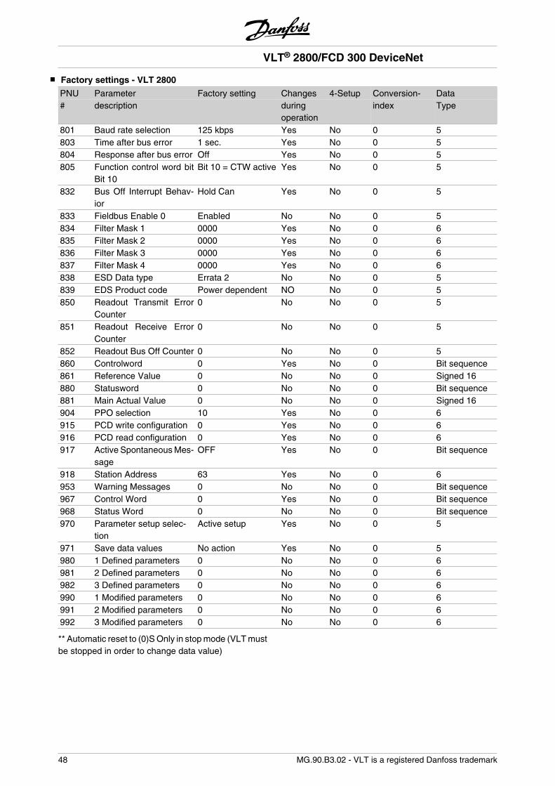
Factory settings - VLT 2800
PNU Parameter Factory setting Changes 4-Setup Conversion- Data# description during
operationindex Type
801 Baud rate selection 125 kbps Yes No 0 5803 Time after bus error 1 sec. Yes No 0 5804 Response after bus error Off Yes No 0 5805 Function control word bit
Bit 10Bit 10 = CTW active Yes No 0 5
832 Bus Off Interrupt Behav-ior
Hold Can Yes No 0 5
833 Fieldbus Enable 0 Enabled No No 0 5834 Filter Mask 1 0000 Yes No 0 6835 Filter Mask 2 0000 Yes No 0 6836 Filter Mask 3 0000 Yes No 0 6837 Filter Mask 4 0000 Yes No 0 6838 ESD Data type Errata 2 No No 0 5839 EDS Product code Power dependent NO No 0 5850 Readout Transmit Error
Counter0 No No 0 5
851 Readout Receive ErrorCounter
0 No No 0 5
852 Readout Bus Off Counter 0 No No 0 5860 Controlword 0 Yes No 0 Bit sequence861 Reference Value 0 No No 0 Signed 16880 Statusword 0 No No 0 Bit sequence881 Main Actual Value 0 No No 0 Signed 16904 PPO selection 10 Yes No 0 6915 PCD write configuration 0 Yes No 0 6916 PCD read configuration 0 Yes No 0 6917 Active Spontaneous Mes-
sageOFF Yes No 0 Bit sequence
918 Station Address 63 Yes No 0 6953 Warning Messages 0 No No 0 Bit sequence967 Control Word 0 Yes No 0 Bit sequence968 Status Word 0 No No 0 Bit sequence970 Parameter setup selec-
tionActive setup Yes No 0 5
971 Save data values No action Yes No 0 5980 1 Defined parameters 0 No No 0 6981 2 Defined parameters 0 No No 0 6982 3 Defined parameters 0 No No 0 6990 1 Modified parameters 0 No No 0 6991 2 Modified parameters 0 No No 0 6992 3 Modified parameters 0 No No 0 6
** Automatic reset to (0)S Only in stop mode (VLT mustbe stopped in order to change data value)
VLT® 2800/FCD 300 DeviceNet
48 MG.90.B3.02 - VLT is a registered Danfoss trademark
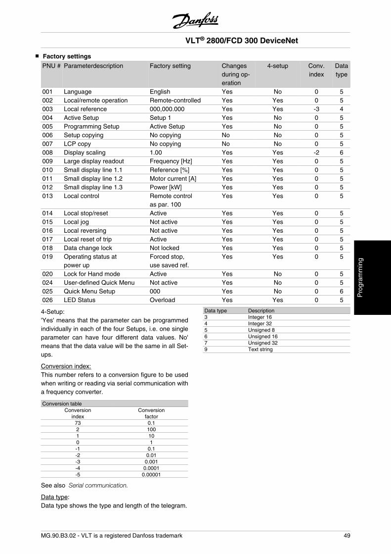
Factory settings
PNU # Parameterdescription Factory setting Changesduring op-eration
4-setup Conv.index
Datatype
001 Language English Yes No 0 5002 Local/remote operation Remote-controlled Yes Yes 0 5003 Local reference 000,000.000 Yes Yes -3 4004 Active Setup Setup 1 Yes No 0 5005 Programming Setup Active Setup Yes No 0 5006 Setup copying No copying No No 0 5007 LCP copy No copying No No 0 5008 Display scaling 1.00 Yes Yes -2 6009 Large display readout Frequency [Hz] Yes Yes 0 5010 Small display line 1.1 Reference [%] Yes Yes 0 5011 Small display line 1.2 Motor current [A] Yes Yes 0 5012 Small display line 1.3 Power [kW] Yes Yes 0 5013 Local control Remote control
as par. 100Yes Yes 0 5
014 Local stop/reset Active Yes Yes 0 5015 Local jog Not active Yes Yes 0 5016 Local reversing Not active Yes Yes 0 5017 Local reset of trip Active Yes Yes 0 5018 Data change lock Not locked Yes Yes 0 5019 Operating status at
power upForced stop,use saved ref.
Yes Yes 0 5
020 Lock for Hand mode Active Yes No 0 5024 User-defined Quick Menu Not active Yes No 0 5025 Quick Menu Setup 000 Yes No 0 6026 LED Status Overload Yes Yes 0 5
4-Setup:'Yes' means that the parameter can be programmedindividually in each of the four Setups, i.e. one singleparameter can have four different data values. No'means that the data value will be the same in all Set-ups.
Conversion index:This number refers to a conversion figure to be usedwhen writing or reading via serial communication witha frequency converter.
Conversion tableConversion
indexConversion
factor73 0.12 1001 100 1-1 0.1-2 0.01-3 0.001-4 0.0001-5 0.00001
See also Serial communication.
Data type:Data type shows the type and length of the telegram.
Data type Description3 Integer 164 Integer 325 Unsigned 86 Unsigned 167 Unsigned 329 Text string
VLT® 2800/FCD 300 DeviceNet
MG.90.B3.02 - VLT is a registered Danfoss trademark 49
Pro
gram
min
g
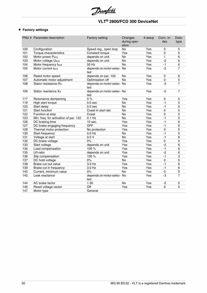
Factory settings
PNU # Parameter-description Factory setting Changesduring oper-ation
4-setup Conv. in-dex
Data-type
100 Configuration Speed reg., open loop No Yes 0 5101 Torque characteristics Constant torque Yes Yes 0 5102 Motor power PM,N depends on unit No Yes 1 6103 Motor voltage UM,N depends on unit No Yes -2 6104 Motor frequency fM,N 50 Hz No Yes -1 6105 Motor current IM,N depends on motor selec-
tedNo Yes -2 7
106 Rated motor speed depends on par. 102 No Yes 0 6107 Automatic motor adjustment Optimisation off No Yes 0 5108 Stator resistance RS depends on motor selec-
tedNo Yes -3 7
109 Stator reactance XS depends on motor selec-ted
No Yes -2 7
117 Resonance dampening 0 % Yes Yes 0 5119 High start torque 0.0 sec No Yes -1 5120 Start delay 0.0 sec No Yes -1 5121 Start function Coast in start del. No Yes 0 5122 Function at stop Coast No Yes 0 5123 Min. freq. for activation of par. 122 0.1 Hz No Yes -1 5126 DC braking time 10 sec. Yes Yes -1 6127 DC brake engaging frequency OFF Yes Yes -1 6128 Thermal motor protection No protection Yes Yes 0 5130 Start frequency 0.0 Hz No Yes -1 5131 Voltage at start 0.0 V No Yes -1 6132 DC brake voltage 0% Yes Yes 0 5133 Start voltage depends on unit Yes Yes -2 6134 Load compensation 100 % Yes Yes -1 6135 U/f-ratio depends on unit Yes Yes -2 6136 Slip compensation 100 % Yes Yes -1 3137 DC hold voltage 0% No Yes 0 5138 Brake cut out value 3.0 Hz Yes Yes -1 6139 Brake cut in frequency 3.0 Hz Yes Yes -1 6140 Current, minimum value 0% No Yes 0 5142 Leak reactance depends on motor selec-
tedNo Yes -3 7
144 AC brake factor 1.30 No Yes -2 5146 Reset voltage vector Off Yes Yes 0 5147 Motor type General
VLT® 2800/FCD 300 DeviceNet
50 MG.90.B3.02 - VLT is a registered Danfoss trademark
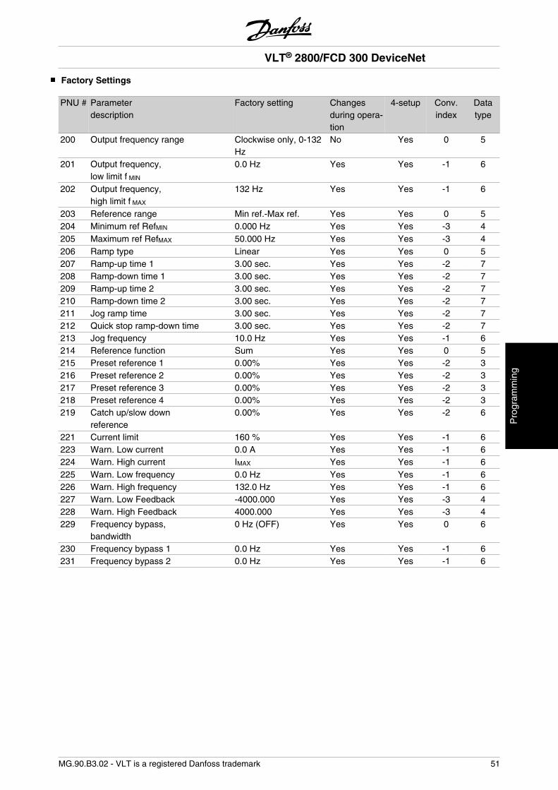
Factory Settings
PNU # Parameterdescription
Factory setting Changesduring opera-tion
4-setup Conv.index
Datatype
200 Output frequency range Clockwise only, 0-132Hz
No Yes 0 5
201 Output frequency,low limit f MIN
0.0 Hz Yes Yes -1 6
202 Output frequency,high limit f MAX
132 Hz Yes Yes -1 6
203 Reference range Min ref.-Max ref. Yes Yes 0 5204 Minimum ref RefMIN 0.000 Hz Yes Yes -3 4205 Maximum ref RefMAX 50.000 Hz Yes Yes -3 4206 Ramp type Linear Yes Yes 0 5207 Ramp-up time 1 3.00 sec. Yes Yes -2 7208 Ramp-down time 1 3.00 sec. Yes Yes -2 7209 Ramp-up time 2 3.00 sec. Yes Yes -2 7210 Ramp-down time 2 3.00 sec. Yes Yes -2 7211 Jog ramp time 3.00 sec. Yes Yes -2 7212 Quick stop ramp-down time 3.00 sec. Yes Yes -2 7213 Jog frequency 10.0 Hz Yes Yes -1 6214 Reference function Sum Yes Yes 0 5215 Preset reference 1 0.00% Yes Yes -2 3216 Preset reference 2 0.00% Yes Yes -2 3217 Preset reference 3 0.00% Yes Yes -2 3218 Preset reference 4 0.00% Yes Yes -2 3219 Catch up/slow down
reference0.00% Yes Yes -2 6
221 Current limit 160 % Yes Yes -1 6223 Warn. Low current 0.0 A Yes Yes -1 6224 Warn. High current IMAX Yes Yes -1 6225 Warn. Low frequency 0.0 Hz Yes Yes -1 6226 Warn. High frequency 132.0 Hz Yes Yes -1 6227 Warn. Low Feedback -4000.000 Yes Yes -3 4228 Warn. High Feedback 4000.000 Yes Yes -3 4229 Frequency bypass,
bandwidth0 Hz (OFF) Yes Yes 0 6
230 Frequency bypass 1 0.0 Hz Yes Yes -1 6231 Frequency bypass 2 0.0 Hz Yes Yes -1 6
VLT® 2800/FCD 300 DeviceNet
MG.90.B3.02 - VLT is a registered Danfoss trademark 51
Pro
gram
min
g
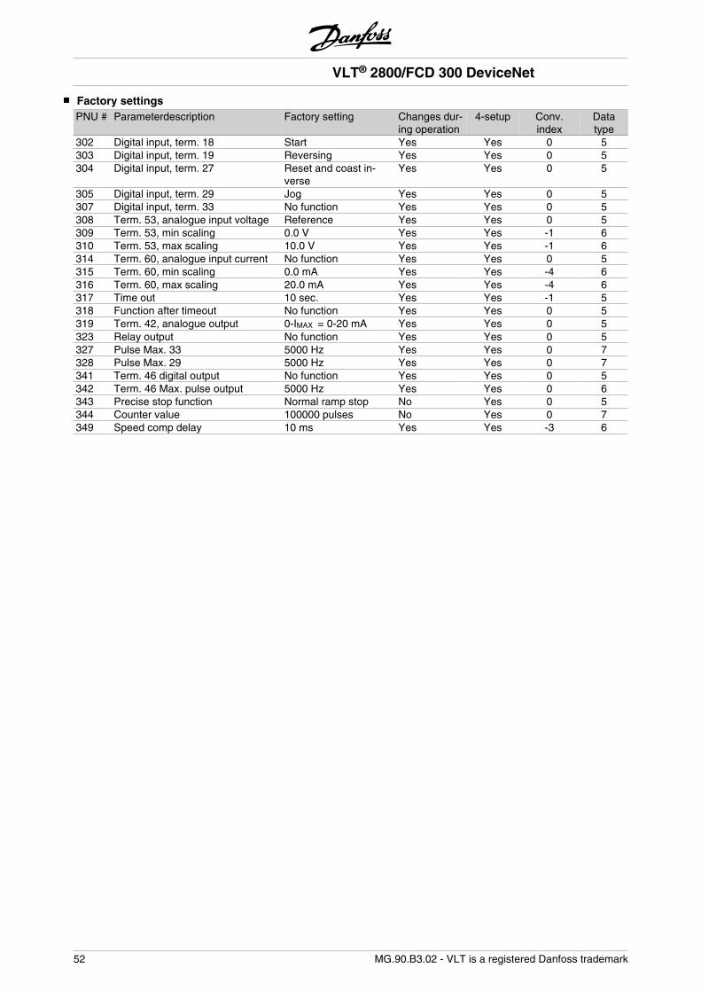
Factory settingsPNU # Parameterdescription Factory setting Changes dur-
ing operation4-setup Conv.
indexDatatype
302 Digital input, term. 18 Start Yes Yes 0 5303 Digital input, term. 19 Reversing Yes Yes 0 5304 Digital input, term. 27 Reset and coast in-
verseYes Yes 0 5
305 Digital input, term. 29 Jog Yes Yes 0 5307 Digital input, term. 33 No function Yes Yes 0 5308 Term. 53, analogue input voltage Reference Yes Yes 0 5309 Term. 53, min scaling 0.0 V Yes Yes -1 6310 Term. 53, max scaling 10.0 V Yes Yes -1 6314 Term. 60, analogue input current No function Yes Yes 0 5315 Term. 60, min scaling 0.0 mA Yes Yes -4 6316 Term. 60, max scaling 20.0 mA Yes Yes -4 6317 Time out 10 sec. Yes Yes -1 5318 Function after timeout No function Yes Yes 0 5319 Term. 42, analogue output 0-IMAX = 0-20 mA Yes Yes 0 5323 Relay output No function Yes Yes 0 5327 Pulse Max. 33 5000 Hz Yes Yes 0 7328 Pulse Max. 29 5000 Hz Yes Yes 0 7341 Term. 46 digital output No function Yes Yes 0 5342 Term. 46 Max. pulse output 5000 Hz Yes Yes 0 6343 Precise stop function Normal ramp stop No Yes 0 5344 Counter value 100000 pulses No Yes 0 7349 Speed comp delay 10 ms Yes Yes -3 6
VLT® 2800/FCD 300 DeviceNet
52 MG.90.B3.02 - VLT is a registered Danfoss trademark
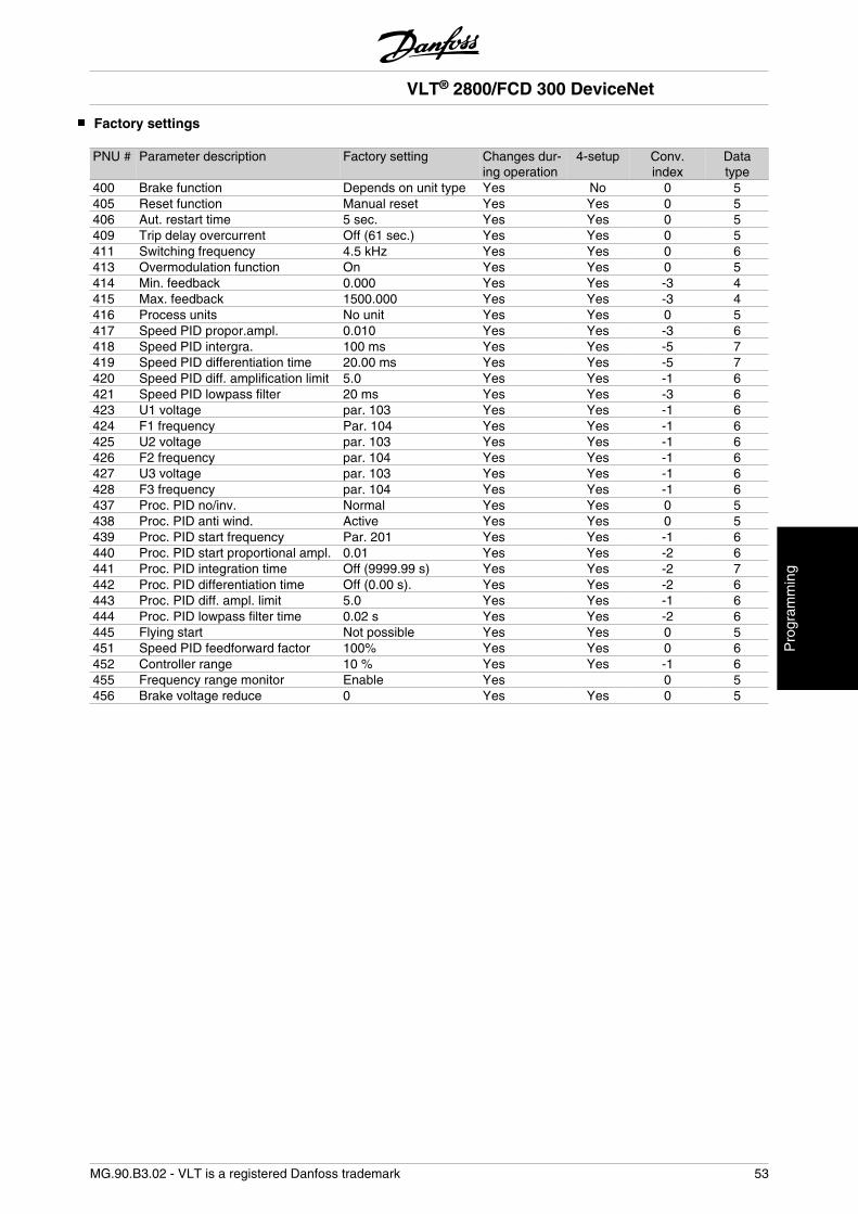
Factory settings
PNU # Parameter description Factory setting Changes dur-ing operation
4-setup Conv.index
Datatype
400 Brake function Depends on unit type Yes No 0 5405 Reset function Manual reset Yes Yes 0 5406 Aut. restart time 5 sec. Yes Yes 0 5409 Trip delay overcurrent Off (61 sec.) Yes Yes 0 5411 Switching frequency 4.5 kHz Yes Yes 0 6413 Overmodulation function On Yes Yes 0 5414 Min. feedback 0.000 Yes Yes -3 4415 Max. feedback 1500.000 Yes Yes -3 4416 Process units No unit Yes Yes 0 5417 Speed PID propor.ampl. 0.010 Yes Yes -3 6418 Speed PID intergra. 100 ms Yes Yes -5 7419 Speed PID differentiation time 20.00 ms Yes Yes -5 7420 Speed PID diff. amplification limit 5.0 Yes Yes -1 6421 Speed PID lowpass filter 20 ms Yes Yes -3 6423 U1 voltage par. 103 Yes Yes -1 6424 F1 frequency Par. 104 Yes Yes -1 6425 U2 voltage par. 103 Yes Yes -1 6426 F2 frequency par. 104 Yes Yes -1 6427 U3 voltage par. 103 Yes Yes -1 6428 F3 frequency par. 104 Yes Yes -1 6437 Proc. PID no/inv. Normal Yes Yes 0 5438 Proc. PID anti wind. Active Yes Yes 0 5439 Proc. PID start frequency Par. 201 Yes Yes -1 6440 Proc. PID start proportional ampl. 0.01 Yes Yes -2 6441 Proc. PID integration time Off (9999.99 s) Yes Yes -2 7442 Proc. PID differentiation time Off (0.00 s). Yes Yes -2 6443 Proc. PID diff. ampl. limit 5.0 Yes Yes -1 6444 Proc. PID lowpass filter time 0.02 s Yes Yes -2 6445 Flying start Not possible Yes Yes 0 5451 Speed PID feedforward factor 100% Yes Yes 0 6452 Controller range 10 % Yes Yes -1 6455 Frequency range monitor Enable Yes 0 5456 Brake voltage reduce 0 Yes Yes 0 5
VLT® 2800/FCD 300 DeviceNet
MG.90.B3.02 - VLT is a registered Danfoss trademark 53
Pro
gram
min
g
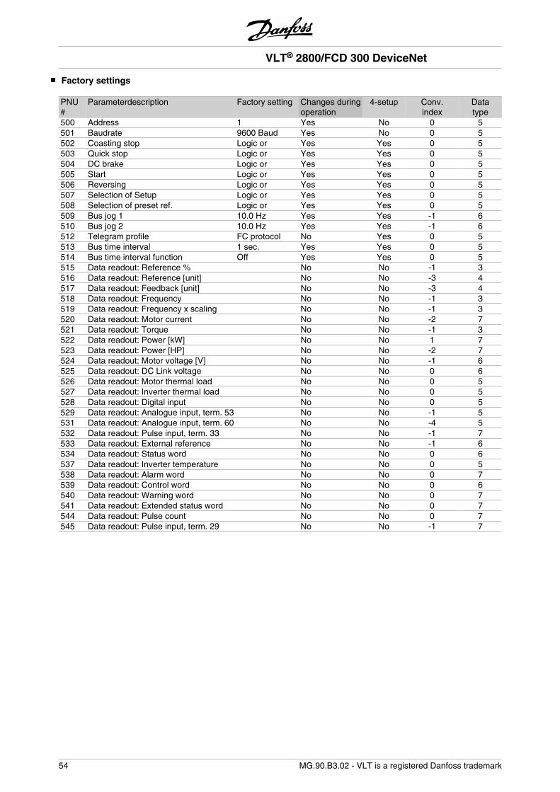
Factory settings
PNU#
Parameterdescription Factory setting Changes duringoperation
4-setup Conv.index
Datatype
500 Address 1 Yes No 0 5501 Baudrate 9600 Baud Yes No 0 5502 Coasting stop Logic or Yes Yes 0 5503 Quick stop Logic or Yes Yes 0 5504 DC brake Logic or Yes Yes 0 5505 Start Logic or Yes Yes 0 5506 Reversing Logic or Yes Yes 0 5507 Selection of Setup Logic or Yes Yes 0 5508 Selection of preset ref. Logic or Yes Yes 0 5509 Bus jog 1 10.0 Hz Yes Yes -1 6510 Bus jog 2 10.0 Hz Yes Yes -1 6512 Telegram profile FC protocol No Yes 0 5513 Bus time interval 1 sec. Yes Yes 0 5514 Bus time interval function Off Yes Yes 0 5515 Data readout: Reference % No No -1 3516 Data readout: Reference [unit] No No -3 4517 Data readout: Feedback [unit] No No -3 4518 Data readout: Frequency No No -1 3519 Data readout: Frequency x scaling No No -1 3520 Data readout: Motor current No No -2 7521 Data readout: Torque No No -1 3522 Data readout: Power [kW] No No 1 7523 Data readout: Power [HP] No No -2 7524 Data readout: Motor voltage [V] No No -1 6525 Data readout: DC Link voltage No No 0 6526 Data readout: Motor thermal load No No 0 5527 Data readout: Inverter thermal load No No 0 5528 Data readout: Digital input No No 0 5529 Data readout: Analogue input, term. 53 No No -1 5531 Data readout: Analogue input, term. 60 No No -4 5532 Data readout: Pulse input, term. 33 No No -1 7533 Data readout: External reference No No -1 6534 Data readout: Status word No No 0 6537 Data readout: Inverter temperature No No 0 5538 Data readout: Alarm word No No 0 7539 Data readout: Control word No No 0 6540 Data readout: Warning word No No 0 7541 Data readout: Extended status word No No 0 7544 Data readout: Pulse count No No 0 7545 Data readout: Pulse input, term. 29 No No -1 7
VLT® 2800/FCD 300 DeviceNet
54 MG.90.B3.02 - VLT is a registered Danfoss trademark
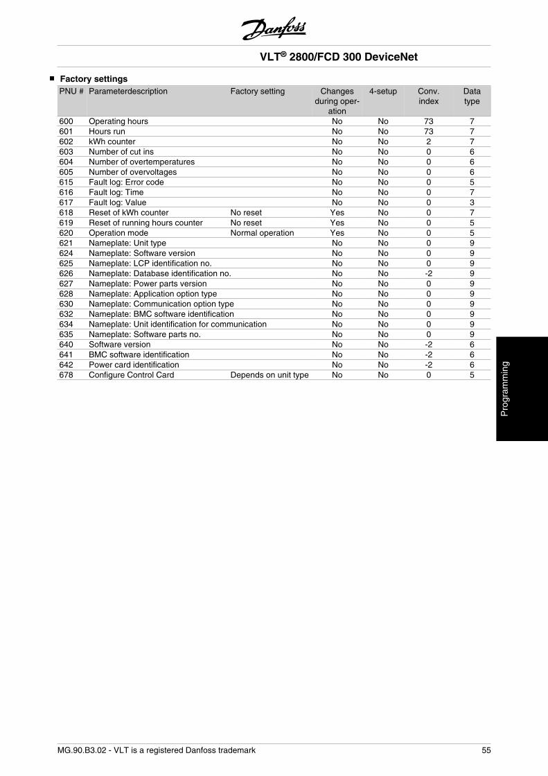
Factory settingsPNU # Parameterdescription Factory setting Changes
during oper-ation
4-setup Conv.index
Datatype
600 Operating hours No No 73 7601 Hours run No No 73 7602 kWh counter No No 2 7603 Number of cut ins No No 0 6604 Number of overtemperatures No No 0 6605 Number of overvoltages No No 0 6615 Fault log: Error code No No 0 5616 Fault log: Time No No 0 7617 Fault log: Value No No 0 3618 Reset of kWh counter No reset Yes No 0 7619 Reset of running hours counter No reset Yes No 0 5620 Operation mode Normal operation Yes No 0 5621 Nameplate: Unit type No No 0 9624 Nameplate: Software version No No 0 9625 Nameplate: LCP identification no. No No 0 9626 Nameplate: Database identification no. No No -2 9627 Nameplate: Power parts version No No 0 9628 Nameplate: Application option type No No 0 9630 Nameplate: Communication option type No No 0 9632 Nameplate: BMC software identification No No 0 9634 Nameplate: Unit identification for communication No No 0 9635 Nameplate: Software parts no. No No 0 9640 Software version No No -2 6641 BMC software identification No No -2 6642 Power card identification No No -2 6678 Configure Control Card Depends on unit type No No 0 5
VLT® 2800/FCD 300 DeviceNet
MG.90.B3.02 - VLT is a registered Danfoss trademark 55
Pro
gram
min
g
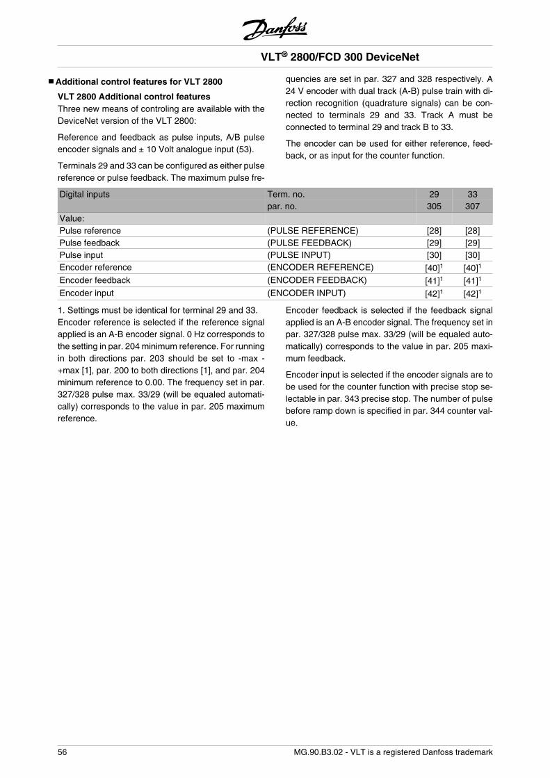
Additional control features for VLT 2800
VLT 2800 Additional control featuresThree new means of controling are available with theDeviceNet version of the VLT 2800:
Reference and feedback as pulse inputs, A/B pulseencoder signals and ± 10 Volt analogue input (53).
Terminals 29 and 33 can be configured as either pulsereference or pulse feedback. The maximum pulse fre-
quencies are set in par. 327 and 328 respectively. A24 V encoder with dual track (A-B) pulse train with di-rection recognition (quadrature signals) can be con-nected to terminals 29 and 33. Track A must beconnected to terminal 29 and track B to 33.
The encoder can be used for either reference, feed-back, or as input for the counter function.
Digital inputs Term. no. 29 33par. no. 305 307
Value:Pulse reference (PULSE REFERENCE) [28] [28]Pulse feedback (PULSE FEEDBACK) [29] [29]Pulse input (PULSE INPUT) [30] [30]Encoder reference (ENCODER REFERENCE) [40]1 [40]1
Encoder feedback (ENCODER FEEDBACK) [41]1 [41]1
Encoder input (ENCODER INPUT) [42]1 [42]1
1. Settings must be identical for terminal 29 and 33.Encoder reference is selected if the reference signalapplied is an A-B encoder signal. 0 Hz corresponds tothe setting in par. 204 minimum reference. For runningin both directions par. 203 should be set to -max -+max [1], par. 200 to both directions [1], and par. 204minimum reference to 0.00. The frequency set in par.327/328 pulse max. 33/29 (will be equaled automati-cally) corresponds to the value in par. 205 maximumreference.
Encoder feedback is selected if the feedback signalapplied is an A-B encoder signal. The frequency set inpar. 327/328 pulse max. 33/29 (will be equaled auto-matically) corresponds to the value in par. 205 maxi-mum feedback.
Encoder input is selected if the encoder signals are tobe used for the counter function with precise stop se-lectable in par. 343 precise stop. The number of pulsebefore ramp down is specified in par. 344 counter val-ue.
VLT® 2800/FCD 300 DeviceNet
56 MG.90.B3.02 - VLT is a registered Danfoss trademark
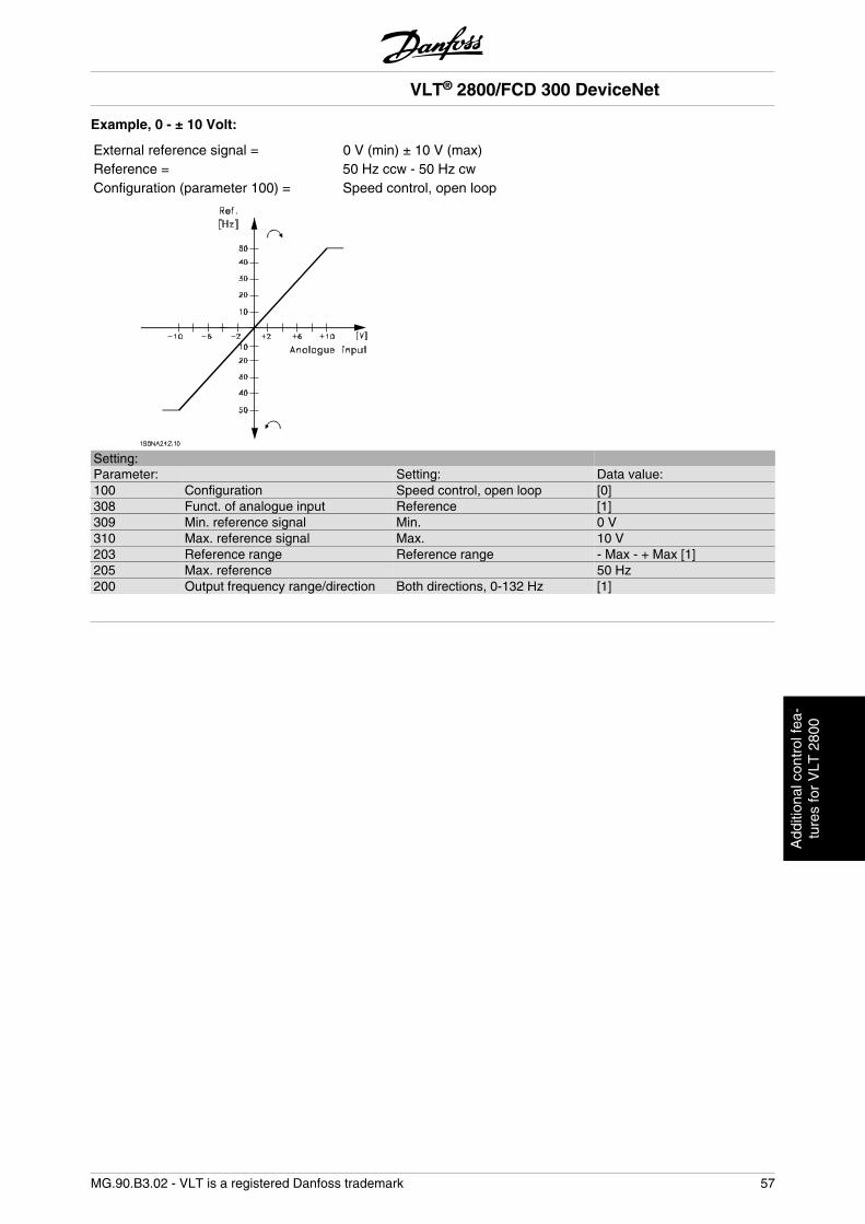
Example, 0 - ± 10 Volt:
External reference signal = 0 V (min) ± 10 V (max)Reference = 50 Hz ccw - 50 Hz cwConfiguration (parameter 100) = Speed control, open loop
Setting:Parameter: Setting: Data value:100 Configuration Speed control, open loop [0]308 Funct. of analogue input Reference [1]309 Min. reference signal Min. 0 V310 Max. reference signal Max. 10 V203 Reference range Reference range - Max - + Max [1]205 Max. reference 50 Hz200 Output frequency range/direction Both directions, 0-132 Hz [1]
VLT® 2800/FCD 300 DeviceNet
MG.90.B3.02 - VLT is a registered Danfoss trademark 57
Add
ition
al c
ontr
ol fe
a-tu
res
for
VLT
280
0
VLT® 2800/FCD 300 DeviceNet
58 MG.90.B3.02 - VLT is a registered Danfoss trademark