vmdc 3.0 design overview design principles - cisco.com · orchestration (figure 2-1). design...
TRANSCRIPT
Design Guide
C H A P T E R 2
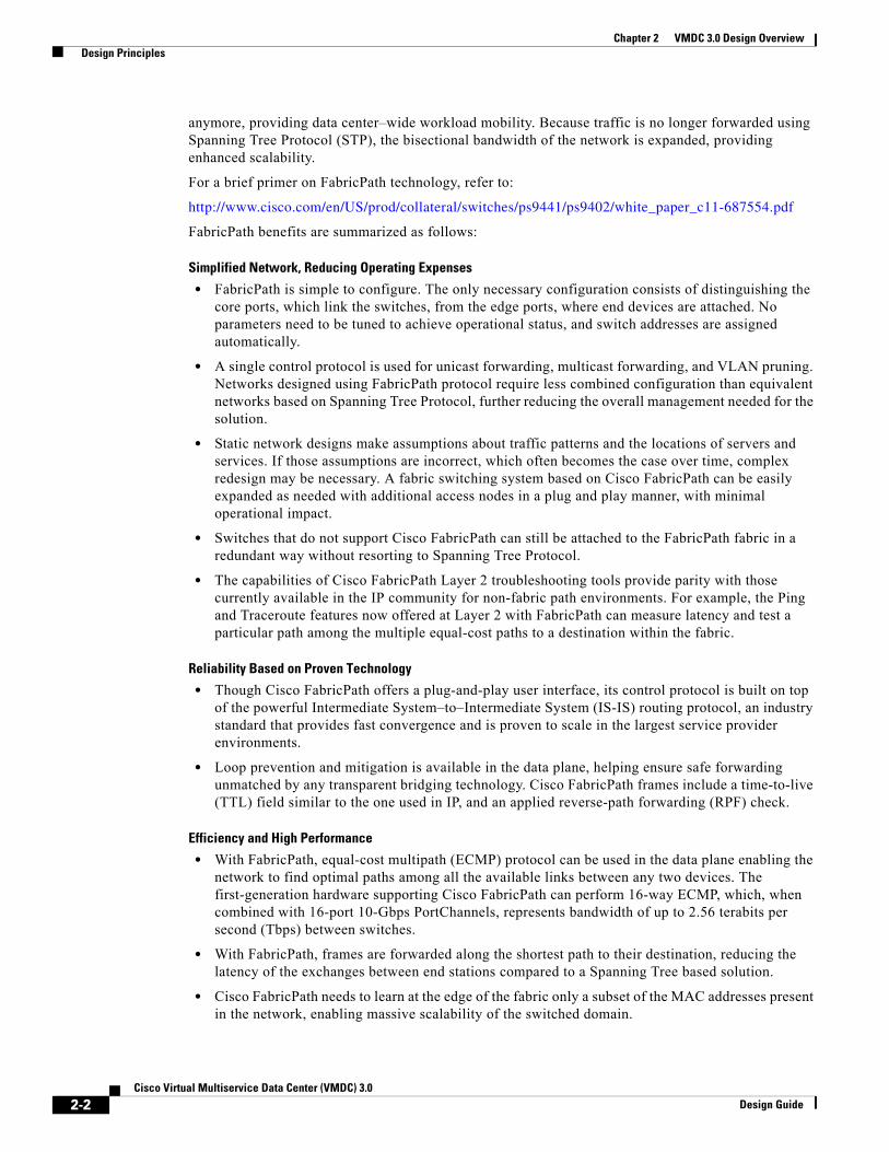
VMDC 3.0 Design OverviewThe Virtual Multiservice Data Center architecture is based on foundation principles of design in modularity, high availability, differentiated service support, secure multi-tenancy, and automated service orchestration (Figure 2-1).
Design PrinciplesDesign principles provide the benefits of streamlined turn-up of new services, maximized service availability, resource optimization, facilitated business compliance and support for self-service IT models, thus maximizing operational efficiency and allowing the private or public cloud provider to focus on their core business objectives.
Figure 2-1 VMDC Design Principles
VMDC 3.0 introduces FabricPath into data center designs because FabricPath allows for the creation of simple, scalable, and efficient Layer 2 domains that apply to many network scenarios. FabricPath brings the stability and scalability of routing to Layer 2. The switched domain does not have to be segmented
2-1Cisco Virtual Multiservice Data Center (VMDC) 3.0
Chapter 2 VMDC 3.0 Design Overview Design Principles
anymore, providing data center–wide workload mobility. Because traffic is no longer forwarded using Spanning Tree Protocol (STP), the bisectional bandwidth of the network is expanded, providing enhanced scalability.
For a brief primer on FabricPath technology, refer to:
http://www.cisco.com/en/US/prod/collateral/switches/ps9441/ps9402/white_paper_c11-687554.pdf
FabricPath benefits are summarized as follows:
Simplified Network, Reducing Operating Expenses
• FabricPath is simple to configure. The only necessary configuration consists of distinguishing the core ports, which link the switches, from the edge ports, where end devices are attached. No parameters need to be tuned to achieve operational status, and switch addresses are assigned automatically.
• A single control protocol is used for unicast forwarding, multicast forwarding, and VLAN pruning. Networks designed using FabricPath protocol require less combined configuration than equivalent networks based on Spanning Tree Protocol, further reducing the overall management needed for the solution.
• Static network designs make assumptions about traffic patterns and the locations of servers and services. If those assumptions are incorrect, which often becomes the case over time, complex redesign may be necessary. A fabric switching system based on Cisco FabricPath can be easily expanded as needed with additional access nodes in a plug and play manner, with minimal operational impact.
• Switches that do not support Cisco FabricPath can still be attached to the FabricPath fabric in a redundant way without resorting to Spanning Tree Protocol.
• The capabilities of Cisco FabricPath Layer 2 troubleshooting tools provide parity with those currently available in the IP community for non-fabric path environments. For example, the Ping and Traceroute features now offered at Layer 2 with FabricPath can measure latency and test a particular path among the multiple equal-cost paths to a destination within the fabric.
Reliability Based on Proven Technology
• Though Cisco FabricPath offers a plug-and-play user interface, its control protocol is built on top of the powerful Intermediate System–to–Intermediate System (IS-IS) routing protocol, an industry standard that provides fast convergence and is proven to scale in the largest service provider environments.
• Loop prevention and mitigation is available in the data plane, helping ensure safe forwarding unmatched by any transparent bridging technology. Cisco FabricPath frames include a time-to-live (TTL) field similar to the one used in IP, and an applied reverse-path forwarding (RPF) check.
Efficiency and High Performance
• With FabricPath, equal-cost multipath (ECMP) protocol can be used in the data plane enabling the network to find optimal paths among all the available links between any two devices. The first-generation hardware supporting Cisco FabricPath can perform 16-way ECMP, which, when combined with 16-port 10-Gbps PortChannels, represents bandwidth of up to 2.56 terabits per second (Tbps) between switches.
• With FabricPath, frames are forwarded along the shortest path to their destination, reducing the latency of the exchanges between end stations compared to a Spanning Tree based solution.
• Cisco FabricPath needs to learn at the edge of the fabric only a subset of the MAC addresses present in the network, enabling massive scalability of the switched domain.
2-2Cisco Virtual Multiservice Data Center (VMDC) 3.0
Design Guide
Chapter 2 VMDC 3.0 Design Overview Terminology
TerminologyFabricPath comprises two types of nodes: spine nodes and leaf nodes. A spine node is one that connects to other switches in the fabric and a leaf node is one that connects to servers. These terms are useful in greenfield scenarios but may be vague for migration situations, where one has built a hierarchical topology and is accustomed to using traditional terminology to describe functional roles. In this document, we expand our set of terms to correlate fabric path nodes and functional roles to hierarchical network terminology. These terms are:
• Aggregation-Edge—This is a FabricPath node that sits at the “edge” of the fabric, corresponding to the aggregation node in a hierarchical topology.
• Access-Edge—This is a Fabricpath node that sits at the edge of the fabric, corresponding to the access node in a hierarchical topology.
These nodes may perform Layer 2 and/or Layer 3 functions. Hence at times, we also refer to an Layer 3 spine or an Layer 3 edge node to clarify the location of Layer 2/Layer 3 boundaries and distinguish between nodes that are performing Layer 3 functions versus Layer 2-only functions.
FabricPath TopologiesFabricPath can be implemented in a variety of network designs, from full-mesh to ring topologies. The following sections discuss three DC design options based on FabricPath that were considered in VMDC 3.0 design and validation. These design options are:
• Typical Data Center Design—This model represents a starting point for FabricPath migration, where FabricPath is simply replaces older layer 2 resilience and loop avoidance technologies, such as vPC and Spanning Tree. This design assumes the existing hierarchical topology, featuring pairs of core, aggregation and/or access switching nodes, remains in place and that FabricPath provides Layer 2 multipathing.
• Switched Fabric Data Center Design—This model represents further horizontal expansion of the infrastructure to leverage improved resilience and bandwidth characterized by a CLOS-based architectural model.
• Extended Switched Fabric Data Center Design—This model assumes further expansion of the data center infrastructure fabric for inter-pod or inter-building communication.
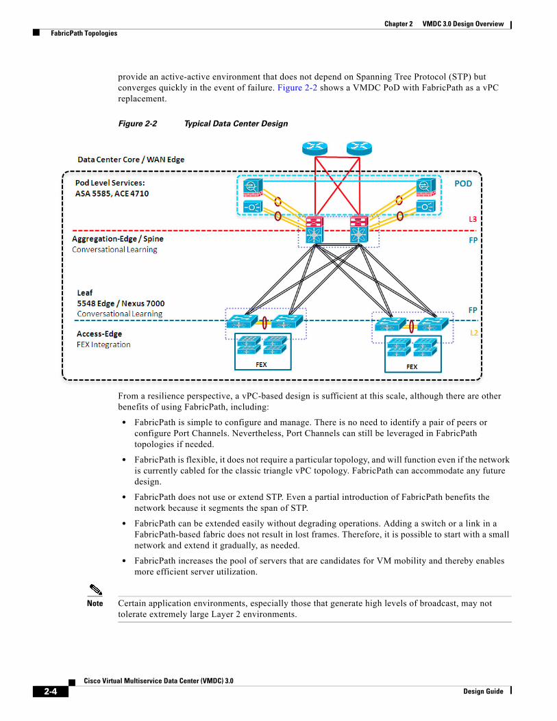
Typical Data CenterA Typical Data Center design is a 2-tier FabricPath design as depicted in Figure 2-2. All VMDC architectures are built around modular building blocks called PoDs. Each PoD uses a localized Services attachment model. Within a pod, Layer 2 switching is handled by Virtual Port Channels (vPC), which
2-3Cisco Virtual Multiservice Data Center (VMDC) 3.0
Design Guide
Chapter 2 VMDC 3.0 Design Overview FabricPath Topologies
provide an active-active environment that does not depend on Spanning Tree Protocol (STP) but converges quickly in the event of failure. Figure 2-2 shows a VMDC PoD with FabricPath as a vPC replacement.
Figure 2-2 Typical Data Center Design
From a resilience perspective, a vPC-based design is sufficient at this scale, although there are other benefits of using FabricPath, including:
• FabricPath is simple to configure and manage. There is no need to identify a pair of peers or configure Port Channels. Nevertheless, Port Channels can still be leveraged in FabricPath topologies if needed.
• FabricPath is flexible, it does not require a particular topology, and will function even if the network is currently cabled for the classic triangle vPC topology. FabricPath can accommodate any future design.
• FabricPath does not use or extend STP. Even a partial introduction of FabricPath benefits the network because it segments the span of STP.
• FabricPath can be extended easily without degrading operations. Adding a switch or a link in a FabricPath-based fabric does not result in lost frames. Therefore, it is possible to start with a small network and extend it gradually, as needed.
• FabricPath increases the pool of servers that are candidates for VM mobility and thereby enables more efficient server utilization.
Note Certain application environments, especially those that generate high levels of broadcast, may not tolerate extremely large Layer 2 environments.
2-4Cisco Virtual Multiservice Data Center (VMDC) 3.0
Design Guide
Chapter 2 VMDC 3.0 Design Overview FabricPath Topologies
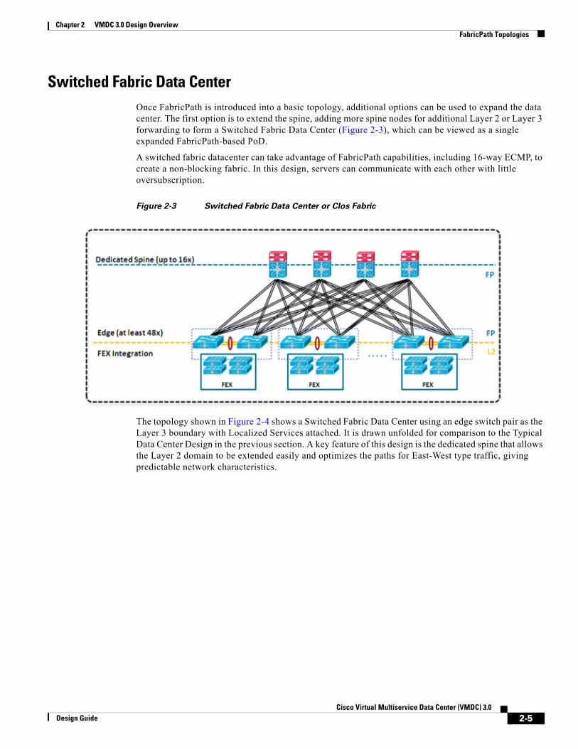
Switched Fabric Data CenterOnce FabricPath is introduced into a basic topology, additional options can be used to expand the data center. The first option is to extend the spine, adding more spine nodes for additional Layer 2 or Layer 3 forwarding to form a Switched Fabric Data Center (Figure 2-3), which can be viewed as a single expanded FabricPath-based PoD.
A switched fabric datacenter can take advantage of FabricPath capabilities, including 16-way ECMP, to create a non-blocking fabric. In this design, servers can communicate with each other with little oversubscription.
Figure 2-3 Switched Fabric Data Center or Clos Fabric
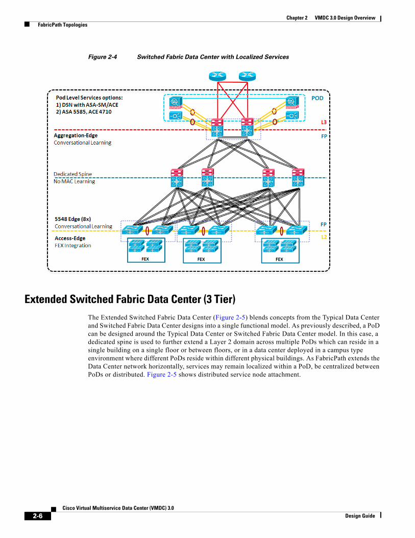
The topology shown in Figure 2-4 shows a Switched Fabric Data Center using an edge switch pair as the Layer 3 boundary with Localized Services attached. It is drawn unfolded for comparison to the Typical Data Center Design in the previous section. A key feature of this design is the dedicated spine that allows the Layer 2 domain to be extended easily and optimizes the paths for East-West type traffic, giving predictable network characteristics.
2-5Cisco Virtual Multiservice Data Center (VMDC) 3.0
Design Guide
Chapter 2 VMDC 3.0 Design Overview FabricPath Topologies
Figure 2-4 Switched Fabric Data Center with Localized Services
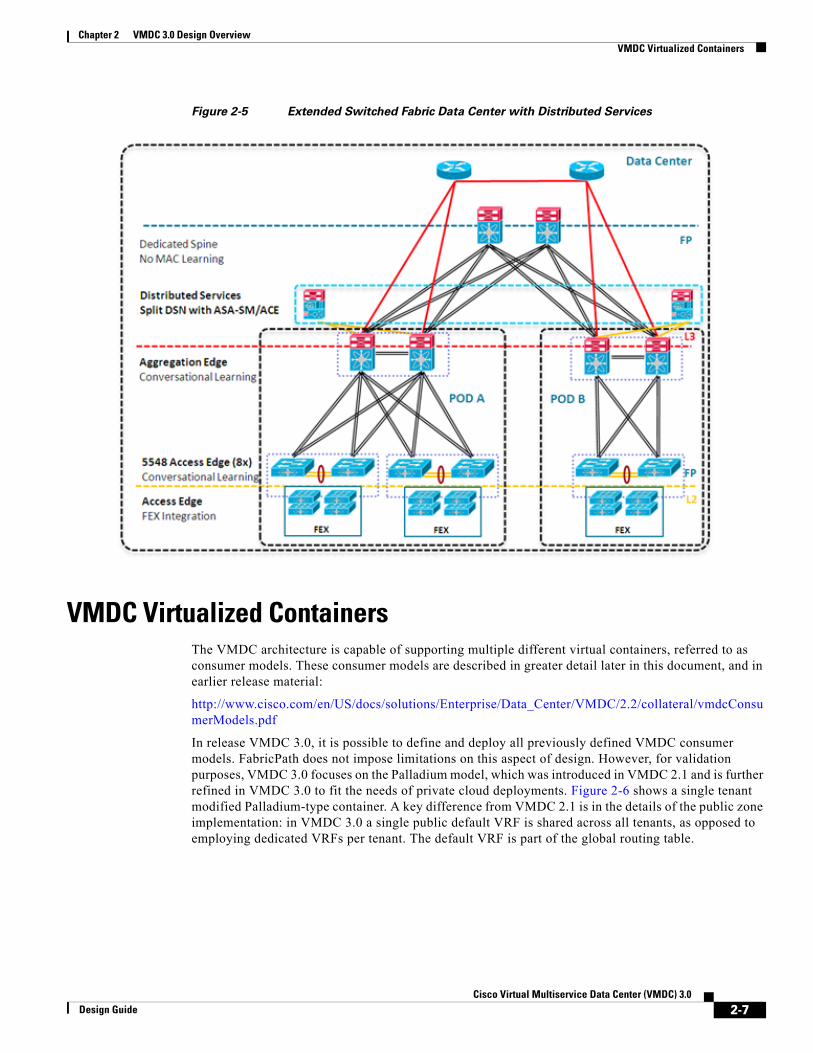
Extended Switched Fabric Data Center (3 Tier)The Extended Switched Fabric Data Center (Figure 2-5) blends concepts from the Typical Data Center and Switched Fabric Data Center designs into a single functional model. As previously described, a PoD can be designed around the Typical Data Center or Switched Fabric Data Center model. In this case, a dedicated spine is used to further extend a Layer 2 domain across multiple PoDs which can reside in a single building on a single floor or between floors, or in a data center deployed in a campus type environment where different PoDs reside within different physical buildings. As FabricPath extends the Data Center network horizontally, services may remain localized within a PoD, be centralized between PoDs or distributed. Figure 2-5 shows distributed service node attachment.
2-6Cisco Virtual Multiservice Data Center (VMDC) 3.0
Design Guide
Chapter 2 VMDC 3.0 Design Overview VMDC Virtualized Containers
Figure 2-5 Extended Switched Fabric Data Center with Distributed Services
VMDC Virtualized ContainersThe VMDC architecture is capable of supporting multiple different virtual containers, referred to as consumer models. These consumer models are described in greater detail later in this document, and in earlier release material:
http://www.cisco.com/en/US/docs/solutions/Enterprise/Data_Center/VMDC/2.2/collateral/vmdcConsumerModels.pdf
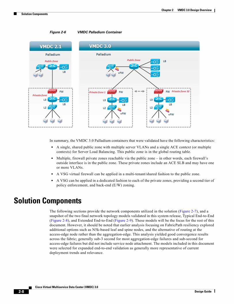
In release VMDC 3.0, it is possible to define and deploy all previously defined VMDC consumer models. FabricPath does not impose limitations on this aspect of design. However, for validation purposes, VMDC 3.0 focuses on the Palladium model, which was introduced in VMDC 2.1 and is further refined in VMDC 3.0 to fit the needs of private cloud deployments. Figure 2-6 shows a single tenant modified Palladium-type container. A key difference from VMDC 2.1 is in the details of the public zone implementation: in VMDC 3.0 a single public default VRF is shared across all tenants, as opposed to employing dedicated VRFs per tenant. The default VRF is part of the global routing table.
2-7Cisco Virtual Multiservice Data Center (VMDC) 3.0
Design Guide
Chapter 2 VMDC 3.0 Design Overview Solution Components
Figure 2-6 VMDC Palladium Container
In summary, the VMDC 3.0 Palladium containers that were validated have the following characteristics:
• A single, shared public zone with multiple server VLANs and a single ACE context (or multiple contexts) for Server Load Balancing. This public zone is in the global routing table.
• Multiple, firewall private zones reachable via the public zone – in other words, each firewall’s outside interface is in the public zone. These private zones include an ACE SLB and may have one or more VLANs.
• A VSG virtual firewall can be applied in a multi-tenant/shared fashion to the public zone.
• A VSG can be applied in a dedicated fashion to each of the private zones, providing a second tier of policy enforcement, and back-end (E/W) zoning.
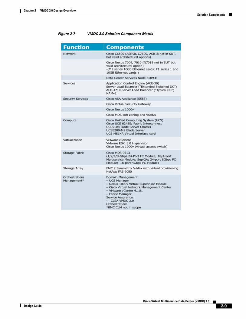
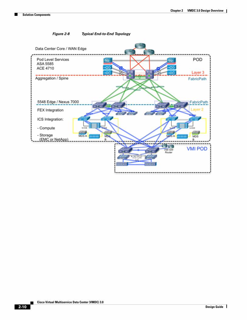
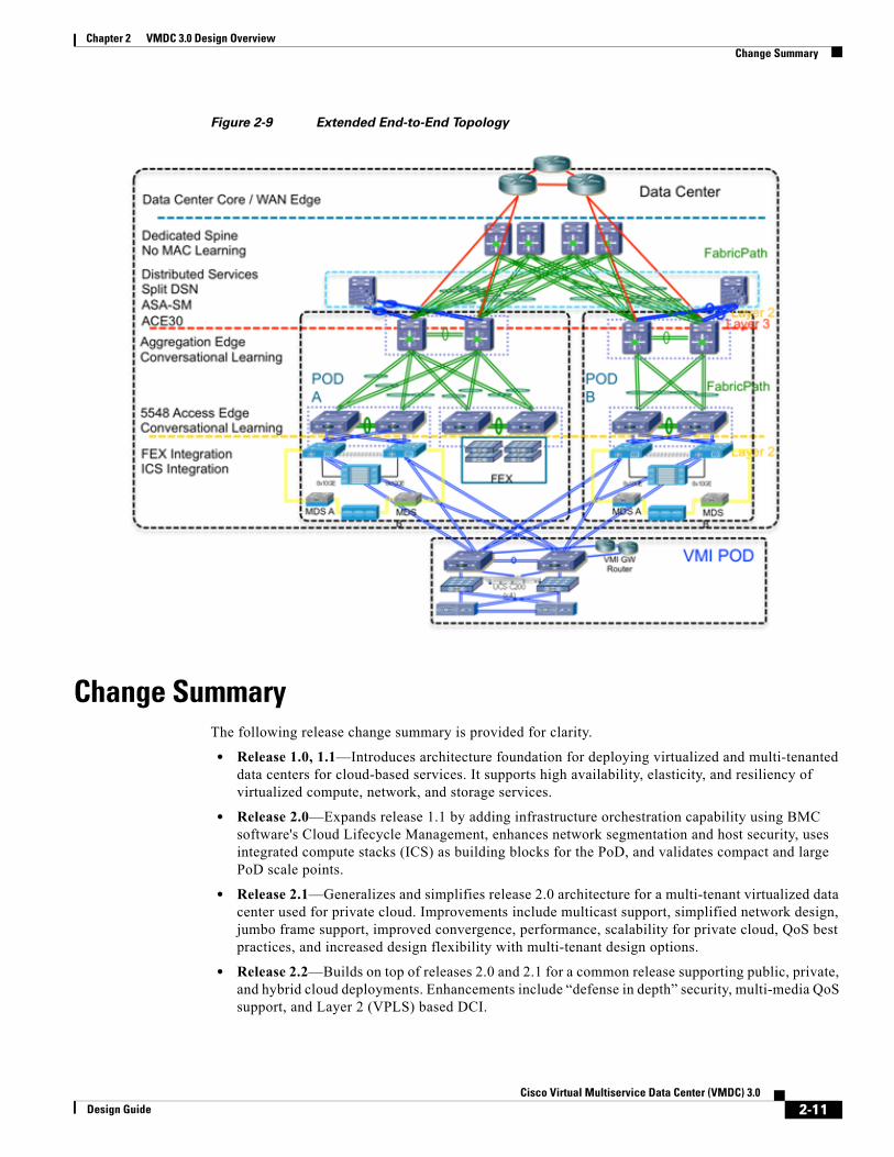
Solution ComponentsThe following sections provide the network components utilized in the solution (Figure 2-7), and a snapshot of the two final network topology models validated in this system release, Typical End-to-End (Figure 2-8), and Extended End-to-End (Figure 2-9). These models will be the focus for the rest of this document. However, it should be noted that earlier analysis focusing on FabricPath resiliency explored additional options such as N5k-based leaf and spine nodes, and the alternative of routing at the access-edge node rather than the aggregation-edge. This analysis yielded good convergence results across the fabric; generally sub-3 second for most aggregation-edge failures and sub-second for access-edge failures but did not include service node attachment. The models included in this document were selected for expanded end-to-end validation as generally more representative of current deployment trends and relevance.
2-8Cisco Virtual Multiservice Data Center (VMDC) 3.0
Design Guide
Chapter 2 VMDC 3.0 Design Overview Solution Components
Figure 2-7 VMDC 3.0 Solution Component Matrix
2-9Cisco Virtual Multiservice Data Center (VMDC) 3.0
Design Guide
Chapter 2 VMDC 3.0 Design Overview Solution Components
Figure 2-8 Typical End-to-End Topology
2-10Cisco Virtual Multiservice Data Center (VMDC) 3.0
Design Guide
Chapter 2 VMDC 3.0 Design Overview Change Summary
Figure 2-9 Extended End-to-End Topology
Change SummaryThe following release change summary is provided for clarity.
• Release 1.0, 1.1—Introduces architecture foundation for deploying virtualized and multi-tenanted data centers for cloud-based services. It supports high availability, elasticity, and resiliency of virtualized compute, network, and storage services.
• Release 2.0—Expands release 1.1 by adding infrastructure orchestration capability using BMC software's Cloud Lifecycle Management, enhances network segmentation and host security, uses integrated compute stacks (ICS) as building blocks for the PoD, and validates compact and large PoD scale points.
• Release 2.1—Generalizes and simplifies release 2.0 architecture for a multi-tenant virtualized data center used for private cloud. Improvements include multicast support, simplified network design, jumbo frame support, improved convergence, performance, scalability for private cloud, QoS best practices, and increased design flexibility with multi-tenant design options.
• Release 2.2—Builds on top of releases 2.0 and 2.1 for a common release supporting public, private, and hybrid cloud deployments. Enhancements include “defense in depth” security, multi-media QoS support, and Layer 2 (VPLS) based DCI.
2-11Cisco Virtual Multiservice Data Center (VMDC) 3.0
Design Guide
Chapter 2 VMDC 3.0 Design Overview Related Documents
Related DocumentsThe following documents are available for reference and consideration.
• Cisco Virtualized Multi-tenant Data Center Design and Implementation Guides, Releases 1.0-2.2
http://www.cisco.com/en/US/solutions/ns340/ns414/ns742/ns743/ns1050/landing_vmdc.html#~releases
• Design Considerations for Classical Ethernet Integration of the Cisco Nexus 7000 M1 and F1 Modules
http://www.cisco.com/en/US/docs/solutions/Enterprise/Data_Center/VMDC/2.6/vmdcm1f1wp.html
• Virtualized Multi-tenant Data Center New Technologies - VSG, Cisco Nexus 7000 F1 Line Cards, and Appliance-Based Services VPLS and EoMPLS Based DCI Solution with nV Edge and vPC
http://www.cisco.com/en/US/docs/solutions/Enterprise/Data_Center/VMDC/2.6/vmdctechwp.html
• Cisco VMDC 2.2 Design Guide
http://www.cisco.com/en/US/docs/solutions/Enterprise/Data_Center/VMDC/2.2/design_guide/vmdcDesign22.html
• Data Center Interconnect over MPLS, Ethernet or IP Transport documents
http://www.cisco.com/en/US/netsol/ns749/networking_solutions_sub_program_home.html
http://www.cisco.com/en/US/netsol/ns975/index.html
• Cloud Service Assurance for VMDC
http://www.cisco.com/en/US/solutions/ns340/ns414/ns742/dz_cloudservice.html
2-12Cisco Virtual Multiservice Data Center (VMDC) 3.0
Design Guide