vms operations, oh&s and maintenance manual operations and... · 4 data signs australia pt ltd...
TRANSCRIPT

V M S O P E R A T I O N S M A N U A L 1
DataSigns
VMS•123
DataSigns
VMS•1237. FORKLIFT POCKETSFor transportationvia truck.
1. SOLAR ARRAYPowered by the sun.Face due North.(Tilt/rotate option)
2. SIM CARDFit SIM card forremote monitoring andcontrol via WebVMS2.
3. ULTRA BRIGHT, WIDE-ANGLE LED’sWith auto-brightnessbased on ambientlight conditions.
5 BATTERY BANKCharged from Solar Array for 24/7continuous operation.
6. WIND-DOWN LEGSMounted on outriggerarms for stability.
8. BALLAST TANKSFill for additional weightfor greater stability inhigher wind conditions.
4. VMS CONTROL BOXLockable. Houses control panelto operate the Sign.
VMS Operations, OH&S and Maintenance Manual
If hiring this VMS, contact Hire Company for assistance.
DataSign-VMS Overview The diagram below shows the location of parts commonly referred to throughout this manual. While some parts change over time, the same concepts apply. Some parts are optional extras and may not be fitted to your Sign.

D A T A S I G N S A U S T R A L I A P T Y L T D2
1. Raise the lid of the VMS Control Box by sliding the concealed latch underneath the lid to the right. The HANDLE for the wind down leg and Jockey wheel is located under the lift up shelf.
2. Engage the park brake on the trailer coupling.
3. Lower the jockey wheel.
4. Unclip the tow coupling. Let the clip rest as shown.
5. Undo the trailer cable and store this under the shelf in the VMS Control box.
6. Undo the safety chain from the vehicle and wind the jockey wheel to allow the tow coupling to be free of the vehicle tow ball.
When arriving on site...
When positioning the Sign, ensure the solar panels will not be in shade during the course of the day. Check with the local council or road authority before placing the DataSign-VMS, depending on the road category.

V M S O P E R A T I O N S M A N U A L 3
7. Extend the 4 outrigger arms.
8. Lower the 4 Wind down legs. A drill adaptor bit for the wind down legs is also supplied in the plastic pouch under the shelf. To speed up this process a battery powered drill can be used.
9. Release the Mast brake.
10. LOOK UP AND CHECK AREA IS CLEAR.
11. Setting up for Operation: Raise the Sign Head using the Hoist Up Switch to clear the cradle and the control box open lid. Rotate the Sign head to face oncoming traffic as shown below and LOCK the mast brake again.
CAUTION: Failure to release the mast brake will cause damage to the mast brake or actuator.
CAUTION: If using a drill, slow it down to avoid kickback as it gets to the end.
Setting up the Solar Panels correctly. It is critical that the solar panels are set up correctly or the sign will not be able to charge the batteries sufficiently to maintain continuous operation. It is absolutely essential that the solar panels are angled up and facing North, especially in the Winter season.See illustration. Use a compass app which can be downloaded free from the App store to assist with the process to find where North actual is. SIGN HEAD
Face directly to oncoming traffic
Traffic flow
SOLAR ARRAYRotate and tilt to face true North

D A T A S I G N S A U S T R A L I A P T Y L T D4
12. If a Manual Solar Tilt/Rotate (STR) system is fitted, rotate and tilt the solar array to face true North (not necessarily the current sun position at the time) as per diagram below. Undo the lock using the handle.
13. Use either the handle or the drill adaptor bit to raise the solar panels
14. LOOK UP AND CHECK AREA IS CLEAR.
15. Release the Mast Brake and Raise the Sign Head to the desired height, normally this is fully raised position. Then lock the Sign Head into place with the Mast Brake again.
16. Feed the security chains through the wheels and fit the locks
17. Secure all other lock-points.
The Sign is set up.
Please read through the remainder of this document to familiarise yourself with this equipment.
• If ballast tanks are fitted, fill both of them with water.
• If ballast tanks are not fully filled, we recommend you do not raise the solar array.
E
W
N
SUMMER PATH OF SUN
WINTER PATH OF SUN
DUENORTH
Starting Up Press the SHOW MESSAGE switch on the VMS Control Panel. For VSLS Signs, the message will display “DRIVE SAFELY” It is updated from WebVMS or local controller after this.
Angle of solar array should be greatest during the winter season.
CAUTION: If using a drill, slow it down to avoid kickback as it gets to the end.
Search for “Correct Solar set-up” video on the Data Signs YouTube channel.

V M S O P E R A T I O N S M A N U A L 5
Starting Up Press the SHOW MESSAGE switch on the VMS Control Panel. For VSLS Signs, the message will display “DRIVE SAFELY” It is updated from WebVMS or local controller after this.
Retractable Drawbar The drawbar can be retracted to reduce the footprint on the ground when setup and to enhance the security of the Trailer.
Ensure the two front wind-down legs are lowered in the down position to prevent tipping whenever the drawbar is retracted.
1. Release the wheel brake. The jockey wheel should only just touch the ground so there is no upward pressure on the drawbar; you should be able to wobble the drawbar. This ensures the pin can move freely.
2. Lift the pin and move right to hold in up position, push the drawbar inwards until nearly all the way, then move pin handle back to the left and push the drawbar fully in, the pin will then drop into place again.
3. Slide lock-pin lever into bracket to hold and secure in place with a lock. To extend the drawbar again, follow the procedure above in reverse.
Search for the “Retractable Drawbar” video on the Data Signs YouTube channel.

D A T A S I G N S A U S T R A L I A P T Y L T D6
Sign Take-down and Safe Transport of the Sign It is crucial that the Sign is correctly taken down and hitched to the towing vehicle. If the Sign comes loose, serious injury or death may result. The correct take-down and hitching procedures are detailed below. Some steps may not apply to smaller model trailers. Trailers are not to be towed behind a truck with 4.5t GVM or higher without a suspension tow hitch/draw bar. Trailers are designed to be towed on bitumen roads.
1. Remove the security chains from through the wheels.
2. Undo the Mast Brake to lower the Sign Head. Lower Sign Head into transport cradle as shown.
3. Lower the Sign Head using the Hoist Down switch on the VMS Control Panel in the VMS Control box.
4. Shutting Down: The sign MUST be BLANK when towed. Blank the sign using the BLANK SIGN switch on the VMS Control Panel.
5. If a Manual Solar Tilt/Rotate (STR) system is fitted, rotate and lower the solar array back into park position. Undo the lock using the handle. Use either the handle or the drill adaptor bit. Make sure the transport pins on either side go into the holding cups when lowering and sit all the way down.
6. Retract the Wind down Legs up and slide in the outriggers on all four sides.
CAUTION: If using a drill, slow it down to avoid kickback as it gets to the end.

V M S O P E R A T I O N S M A N U A L 7
7. Pull the spring pin and rotate the wind-down legs upside down, ensuring the spring pin goes back in to lock the wind-down leg in the upwards position.
8. Use the Jockey wheel to lower the tow coupling onto the tow ball. Ensure the tow coupling fits snugly onto the tow ball of the towing vehicle. This is discussed further in this manual.
9. Do up the safety chain.
10. Wind up the jockey wheel and lift to slot into position. Make sure the jockey wheel does not move once in the towing position.
11. Ensure the Reversing lock on the tow coupling is released before travelling, as shown.
12. Release the hand brake if this is still engaged.
13. Plug the tow cable into the plug on the trailer and the towing vehicle. Check the trailer lights are functioning correctly.
14. Walk around the Sign to confirm that it is ready for transport and that no steps were missed. The Maximum recommended tow speed is 80 km/h.
Consider the Sign Height when towing. When towing the Sign, bridges and other low obstacles may be encountered. Towing Heights: DataSign-A, A5: 2160 mm, DataSign-B,B5,C,C5: 2550 mm.

D A T A S I G N S A U S T R A L I A P T Y L T D8
The Battery Charger is located under the shelf in the VMS Control box.The battery charger has an On/Off switch and a fuse located on the side. Normally this switch is left in the ON position.
1. Feed the cable through the slot on the side of the VMS Control box. This holds the cable in place when shelf and lid are closed.
2. To charge the batteries, plug the power cable into 240V Mains power.
3. It takes about 15 hours to fully charge the batteries from a minimum acceptable charge level.
Battery Charger As required by Australian Standards.
The solar regulator is situated in the VMS Control box, under the shelf.
If the solar regulator does not appear to be on, check the SOLAR fuse is operational. The SOLAR FUSE can be found on the left of the solar regulator.
The Amps will be high when the solar panel are facing towards the Sun, as the Battery charge level goes up the Amps will decrease.
If the screen is not showing the Amps, press the Page button on the left as shown, to get to this screen.
Keep pressing the Page button to Read Battery Voltage as well.
The Solar Regulator
If fitted, the radar unit is a small black box located on the top/right of the Sign head as indicated here with an orange circle.The radars are completely digital in signal processing and inherently accurate by design and require no calibration after they leave the suppliers’ factory.
Radar Unit, if fitted No Calibration Required.

V M S O P E R A T I O N S M A N U A L 9
The procedure below outlines how to fill and empty the ballast tanks with water, Each tank has approximately a 140 litre capacity thus adding some 280 KG of ballast. The two ballast tank filling caps are located towards the rear and front of the trailer.
1. Use the handle to lock and unlock the cap.
2. Turn and lift the handle to unlock.
3. Fill with water only.
4. To close the ballast tank cap, follow the instructions provided on the cap: PRESS – CLICK – LOCK.
5. Press cap down, click into place, and then lock. When the diamonds on the clear inner plastic and the outer black plastic are aligned, the cap is in lock position. The red indicator will be visible when the cap is securely locked.
6. To drain the water, first open the ballast tank caps. Then use the plugs located at the bottom of each tank. There are two plugs on the front ballast tank and three plugs on the rear ballast tank. Use a coin to undo the plugs to empty the water out of the ballast tanks. The plug has a holder so it won’t get lost as the water drains.
Ballast Tanks As required for Australian standards Wind rating.

D A T A S I G N S A U S T R A L I A P T Y L T D10
For trouble free operation of your DataSign-VMS, Data Signs offer scheduled servicing of your equipment. Please contact one of our
Service Centers to enquire about your servicing options.
Data Signs recommends a periodic service every 6 months.
The Signs are fitted with either a Fixed or Manual STR solar array.
The solar panels are used to charge a 12V battery array via a solar regulator. The battery array powers the Sign. The batteries are considered flat when they get below 10.5 V. Once the voltage on the batteries gets this low, the Sign will go into Battery Recharge mode and the display will blank.
If your batteries are low:
• Ensure the solar panels are kept clean and free of dust.• Check that Sign is positioned so the solar panels receive at least 6 hours of sunlight
per day. Otherwise, the batteries will eventually go flat.
Solar Array and Batteries
VMS Maintenance Guide

V M S O P E R A T I O N S M A N U A L 11
Tow Coupling Adjustment Adjust the tow coupling to fit snugly onto the tow ball of the towing vehicle to improve tow ride. In Australia, the tow coupling is designed to fit a 50mm ball. This adjustment is not completed during manufacture as each tow ball may be a slightly different diameter due to wear, or other factors. This is a guide only, please view the disclaimer at the end of the document. Additionally, ensure tow ball is at the correct height to tow the trailer.
1. Release the 19mm locking nut.
2. Undo the locking nut to give some leeway.
3. Using a flat-head screw driver on the slot on top of the pin, turn until tight, and then loosen very slightly. This will pull the coupling forward onto the tow ball and grip it.
4. Check that you can still unhook the coupling without too much effort, but maintaining a tight fit on the tow ball when attached.
5. Tighten the locking nut firmly.
6. Note: when towing, ensure the reverse-lock is not engaged. Push out of the way, as shown.

D A T A S I G N S A U S T R A L I A P T Y L T D12
Disconnect the power to the Sign for long-term storage (i.e. longer than a month), for long distance transport, or when working on the Sign. To disconnect the power follow the instructions below.
1. Open the VMS Control box.2. Lift the shelf to access the fuse board.3. To remove Sign power, pull out the SIGN
SUPPLY fuse.
To restore Sign power, insert the SIGN SUPPLY fuse. Push down to ensure it is properly fitted.
For access to the sign head, use the “T Tool” provided in the pouch under the control box lid
NOTE: The method to OPEN and CLOSE is to PUSH and ROTATE 1/4 TURN TO THE RIGHT.
The locking pin is spring loaded and will pop out when released.
Removing/Restoring Sign Power
Access to sign head
CAUTION: If working on the Sign for repair (i.e. welding) disconnect ALL fuses.
Notes for Undercover storage: Storage outside is recommended so batteries can maintain charge via the solar array. If storing the Sign undercover for a long-term (i.e over one month), unplug the SIGN SUPPLY fuse. Please be aware that the batteries will drain over time; therefore fitting a battery charger is recommended. Battery warranty is voided if batteries allowed to completely drain.
CAUTION: DO NOT ROTATE LEFT AT ANY TIME

V M S O P E R A T I O N S M A N U A L 13
The electric actuator is used to raise and lower the Sign Head. In the event of low voltage, defective batteries or actuator failure, the electric actuator can be manually lowered. The service tools for this maintenance function may be purchased from Data Signs. The M5 and M6 Hex tools bits must be 250mm in length.
Electric Actuator – Manual Hand Crank
1. The power supply MUST be disconnected during manual lowering operation, pull out the ALL the fuses found under the shelf in the VMS Control Box.
2. Release the Mast brake. Complete the following underneath the trailer chassis.
3. Remove the cover screw using the M5 HEX TOOL BIT from underneath the actuator. (keep it safe to put it back in again afterwards)
4. Insert the M6 HEX TOOL BIT in 10mm past the cover screw thread section and begin winding down the actuator SLOWLY! Otherwise there is a potential risk of electricity being generated as it winds and may damage the actuator.
5. Before lowering completely, make sure the Sign cradle is lined up as shown.
6. Stop winding when lowered to the base.
7. Once completed, lock Mast brake.8. Put back the cover screw using the M5 HEX TOOL BIT into the
actuator.9. Effect service to sign as necessary
CAUTION: Manually lowering too far will cause mechanical damage.
D A T A S I G N S A U S T R A L I A P T Y L T D14
Regularly check the tyre pressure. At the same time check tyre condition and that the wheel nuts are tight. Every 6 months—and after a few months of use have a qualified mechanic check the wheel bearings. Grease the wheel bearings every 12 months under normal operating conditions. More frequently for adverse/harsh road or operating conditions. Further, check after having travelled 1500 km.
Torque setting for wheel nuts: 65ibs.ft or 90Nm
The tyre pressures for each Sign model are detailed on the VIN plate. Ensure wheel nuts are tightened according to manufacturer specifications for this trailers’ tyre size. If unsure, contact your local mechanic. Tire pressure of 55 PSI is recommended.
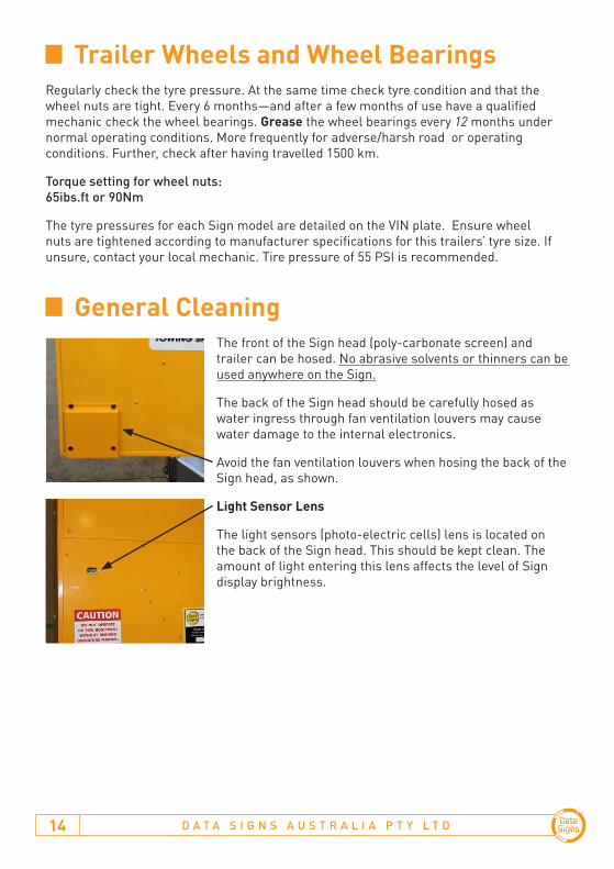
The front of the Sign head (poly-carbonate screen) and trailer can be hosed. No abrasive solvents or thinners can be used anywhere on the Sign.
The back of the Sign head should be carefully hosed as water ingress through fan ventilation louvers may cause water damage to the internal electronics.
Avoid the fan ventilation louvers when hosing the back of the Sign head, as shown.
Light Sensor Lens
The light sensors (photo-electric cells) lens is located on the back of the Sign head. This should be kept clean. The amount of light entering this lens affects the level of Sign display brightness.
Trailer Wheels and Wheel Bearings
General Cleaning

Programming Your Sign

D A T A S I G N S A U S T R A L I A P T Y L T D16
Data Signs WebVMS2™ Data Signs WebVMS2™ runs on all web-browsers (although it is optimized to work best on Google Chrome). It is best suited to run on a PC or Laptop with a good size screen. It can also work with various popular devices such as iPad, Samsung tablet, etc.
AppVMS™
A portable smart phone App, AppVMS™ is also available on the App Store or Google Play.
These web-based applications allow you to update your Sign with new messages, track the location of each Sign, check the battery voltage, schedule message changes, setup the radar and much more!
Go to www.webvms2.net.
To have your Sign activated on WebVMS2™, contact Data Signs.
WebVMS2™ Data Signs Web-based Sign Programming.
A correctly configured SIM card is required for all remote programming.

V M S O P E R A T I O N S M A N U A L 17
VMS Computer QuickStart Guide
VMS Computer
For this manual convention, Sign means Data Signs Variable Message Signs or VMS.
The VMS COMPUTER is a requirement as part of the Australian Standards AS4852.2-2009 Portable signs, to be fitted to your Sign. It is however purchased at customer discretion.
It is used to program, monitor and facilitate changing settings at the Sign.
D A T A S I G N S A U S T R A L I A P T Y L T D18
Start-up 19Creating a Message 20Creating a More Featured Message 22
Predefined Images 25Editing a Saved Message 28Show a previously Saved Message 30Delete Messages 30Show WebVMS™ Messages 31Resume WebVMS™ Message 31
Security Settings 32Change Login Pin 32Enable Login 32Change VMS Password 33Enable VMS Password Login 33
Advanced Feature Menu options 34If no response from Sign 34
Contents
V M S O P E R A T I O N S M A N U A L 19
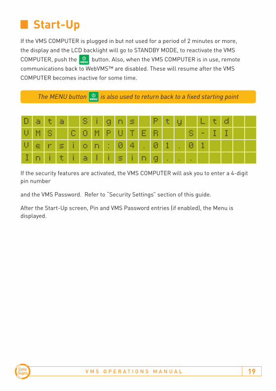
Start-Up If the VMS COMPUTER is plugged in but not used for a period of 2 minutes or more, the display and the LCD backlight will go to STANDBY MODE, to reactivate the VMS COMPUTER, push the button. Also, when the VMS COMPUTER is in use, remote communications back to WebVMS™ are disabled. These will resume after the VMS COMPUTER becomes inactive for some time.
D a t a
S i g n s P t y L t d
V M S C O M P U T E R S - I I
V e r s i o n : 0 4 . 0 1 . 0 1
I n i t i a l i s i n g . . .
If the security features are activated, the VMS COMPUTER will ask you to enter a 4-digit pin number
and the VMS Password. Refer to “Security Settings” section of this guide.
After the Start-Up screen, Pin and VMS Password entries (if enabled), the Menu is displayed.
The MENU button is also used to return back to a fixed starting point

D A T A S I G N S A U S T R A L I A P T Y L T D20
Important note:
Properly Formatted Message, using multiple frames.
Too difficult to read at approaching speed
The following is a step-by-step tutorial detailing how to use the VMS COMPUTER to create a message and show it on the Sign.
If Creating messages for Traffic Management use, it is recommended that you limit the message to only 3 lines of text high and 8 letters wide. This is to allow vehicles approaching at speed to be able to read and interpret the message easily. See example below of a properly formatted message as recommended by the Australian Standards AS4852.2-2009 for Portable Signs.
1. Navigate the Menu screen using the and keys to select the ‘Create New Message’ option. Once the asterisk is beside the ‘Create New Message’ option, push the button.
M E N U - P a g e - 1
* C r e a t e N e w M e s s a g e
S h o w S a v e d M e s s a g e
E d i t M e s s a g e
The message creation screen will appear as shown on the next page.
• The left side of the screen shows the number of lines used for the current frame.
• The middle of the screen is where the message text can be entered
• The right side of the screen shows the current frame that you are on and also the current frame display time.
Creating a Message

V M S O P E R A T I O N S M A N U A L 21
L 1 | | F 1
L 2 | | / 1
L 3 | |
| | T m 2
2. Enter text in this frame as shown below. To move up and down through the frame text, use the and keys. The cursor will move forwards or backwards, character by character.
L 1 | R O A D | F 1
L 2 | W O R K | / 1
L 3 | A H E A D |
| | T m 2
3. The creation of our first message is complete. Now we want to show the message on the Sign. Push the button. The ‘MESSAGE OPTIONS’ screen will appear. Select ‘Show Msg, No Save’ to show the message on your Sign.
M E S S A G E O P T I O N S -
S h o w M s g & S a v e
* S h o w M s g , N o
s a v e
S a v e M s g O n l y Your message should now be displaying on the Sign.

D A T A S I G N S A U S T R A L I A P T Y L T D22
The following is a step-by-step tutorial detailing how to create a more featured message to show on your Sign. Complete the following steps from the main MENU screen. If you are not on the main MENU screen, press the button.
1. Select the ‘Create New Message’ option and push the button
M E N U - P a g e - 1* C r e a t e N e w M e s s a g e
S h o w S a v e d M e s s a g e
E d i t M e s s a g e
2. The message creation screen will appear as shown below.
L 1 |
| F 1
L 2 |
| / 1
L 3 | |
|
| T m 2
3. Change to a 2 LINE message, by selecting the Button and then type “HELLO DRIVERS” as shown below.
L 1 | H E L L O
| F 1
L 2 | D R I V E R S | / 1
| |
|
| T m 2
4. You can add additional frames to your message. Pushing the button will create a new blank frame and the Frame# counter will increase, as highlighted.
L 1 |
| F 2
L 2 | | / 2
L 3 | |
|
| T m 2
Creating a More Featured Message

V M S O P E R A T I O N S M A N U A L 23
NOTE: To Left align the text, press the button twice. This applies for all line types
5. Type in the following text into the frame, “Roadwork Ahead”
• Press the button to switch to CAPITAL letters and vice versa to switch back to Lower case letters.
• Likewise, the button is used to select the symbols on the buttons 1 through to P in the top right hand corner on each button, for example press the key and then the button to select the ! symbol.
L 1 | R o a d | F 2
L 2 | W o r k | / 2
L 3 | A h e a d ! |
| | T m
• You can apply a different colour to each line on the frame. Use the button and then press the colour you want to use. Use the and keys first to select the line, then select the colour. If you select the top line only then the whole frame will be shown that colour.
• You can also change the amount of time (in seconds) that the current frame is to be displayed.
6. Type “Please Drive Safely”, and select the colours, Green, Yellow and White as shown.
L 1 g | P l e a s e | F 3
L 2 y | D r i v e | / 3
L 3 w | S a f e l y |
| | T m 5
7. Changing FRAME TIME: Push the button. The “Frame Time” screen is displayed. Enter a number from 1 to 9 to set how many seconds this frame will show on the Sign. Push the button to set the value and return to the message editing screen. For this example, enter 5 seconds. This is then shown, as highlighted above.

D A T A S I G N S A U S T R A L I A P T Y L T D24
F R A M E T I M E -
E n t e r D i s p l a y T i m e
f o r f r a m e : 5
( T h e n p r e s s E N T E R ) Note: The frame time for each frame is normally set to 2 Seconds
8. The FIRST, PREVIOUS, NEXT, and LAST buttons are used to move between frames. To go back to the LAST frame, push the button.
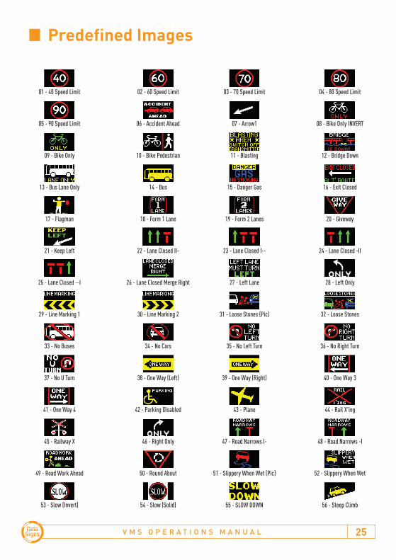
9. Adding an IMAGE: To add an image to the message, create a new frame by pressing the key and then push the button. The “Select Image” screen is displayed. For the purpose of this example, select 04 which is the ‘80 Speed Limit’ image. Or use the and keys, to select the desired image next to the asterisk. Push the button to select this image.
P R E D E F I N E D I M A G E S > 0 4
4 0 S p e e d L i m i t
6 0 S p e e d L i m i t
* 8 0 S p e e d L i m i t
I M G | 8 0 | F 4
# 4 | S p e e d | / 4
| L i m i t |
| | T m 2
V M S O P E R A T I O N S M A N U A L 25
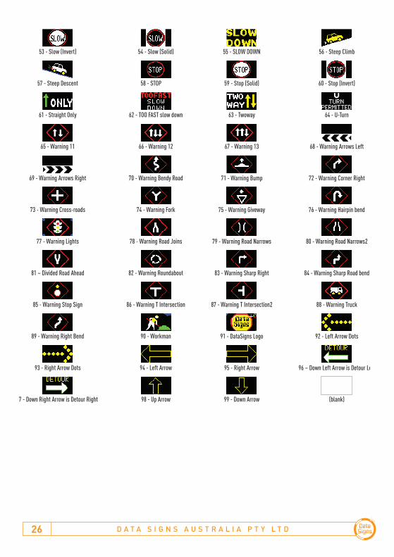
Predefined Images
01 - 40 Speed Limit
05 - 90 Speed Limit
09 - Bike Only
13 - Bus Lane Only
17 - Flagman
21 - Keep Left
25 - Lane Closed --I
29 - Line Marking 1
33 - No Buses
37 - No U Turn
41 - One Way 4
45 - Railway X
49 - Road Work Ahead
53 - Slow (Invert)
57 - Steep Descent
61 - Straight Only
65 - Warning 11
69 - Warning Arrows Right
73 - Warning Cross-roads
77 - Warning Lights
81 – Divided Road Ahead
85 - Warning Stop Sign
89 - Warning Right Bend
93 - Right Arrow Dots
97 - Down Right Arrow is Detour Right
02 - 60 Speed Limit
06 - Accident Ahead
10 - Bike Pedestrian
14 - Bus
18 - Form 1 Lane
22 - Lane Closed II-
26 - Lane Closed Merge Right
30 - Line Marking 2
34 - No Cars
38 - One Way (Left)
42 - Parking Disabled
46 - Right Only
50 - Round About
54 - Slow (Solid)
58 - STOP
62 - TOO FAST slow down
66 - Warning 12
70 - Warning Bendy Road
74 - Warning Fork
78 - Warning Road Joins
82 - Warning Roundabout
86 - Warning T Intersection
90 - Workman
94 - Left Arrow
98 - Up Arrow
03 - 70 Speed Limit
07 - Arrow1
11 - Blasting
15 - Danger Gas
19 - Form 2 Lanes
23 - Lane Closed I--
27 - Left Lane
31 - Loose Stones (Pic)
35 - No Left Turn
39 - One Way (Right)
43 - Plane
47 - Road Narrows I-
51 - Slippery When Wet (Pic)
55 - SLOW DOWN
59 - Stop (Solid)
63 - Twoway
67 - Warning 13
71 - Warning Bump
75 - Warning Giveway
79 - Warning Road Narrows
83 - Warning Sharp Right
87 - Warning T Intersection2
91 - DataSigns Logo
95 - Right Arrow
99 - Down Arrow
04 - 80 Speed Limit
08 - Bike Only INVERT
12 - Bridge Down
16 - Exit Closed
20 - Giveway
24 - Lane Closed -II
28 - Left Only
32 - Loose Stones
36 - No Right Turn
40 - One Way 3
44 - Rail X'ing
48 - Road Narrows -I
52 - Slippery When Wet
56 - Steep Climb
60 - Stop (Invert)
64 - U-Turn
68 - Warning Arrows Left
72 - Warning Corner Right
76 - Warning Hairpin bend
80 - Warning Road Narrows2
84 - Warning Sharp Road bend
88 - Warning Truck
92 - Left Arrow Dots
96 – Down Left Arrow is Detour Left
(blank)
D A T A S I G N S A U S T R A L I A P T Y L T D26
01 - 40 Speed Limit
05 - 90 Speed Limit
09 - Bike Only
13 - Bus Lane Only
17 - Flagman
21 - Keep Left
25 - Lane Closed --I
29 - Line Marking 1
33 - No Buses
37 - No U Turn
41 - One Way 4
45 - Railway X
49 - Road Work Ahead
53 - Slow (Invert)
57 - Steep Descent
61 - Straight Only
65 - Warning 11
69 - Warning Arrows Right
73 - Warning Cross-roads
77 - Warning Lights
81 – Divided Road Ahead
85 - Warning Stop Sign
89 - Warning Right Bend
93 - Right Arrow Dots
97 - Down Right Arrow is Detour Right
02 - 60 Speed Limit
06 - Accident Ahead
10 - Bike Pedestrian
14 - Bus
18 - Form 1 Lane
22 - Lane Closed II-
26 - Lane Closed Merge Right
30 - Line Marking 2
34 - No Cars
38 - One Way (Left)
42 - Parking Disabled
46 - Right Only
50 - Round About
54 - Slow (Solid)
58 - STOP
62 - TOO FAST slow down
66 - Warning 12
70 - Warning Bendy Road
74 - Warning Fork
78 - Warning Road Joins
82 - Warning Roundabout
86 - Warning T Intersection
90 - Workman
94 - Left Arrow
98 - Up Arrow
03 - 70 Speed Limit
07 - Arrow1
11 - Blasting
15 - Danger Gas
19 - Form 2 Lanes
23 - Lane Closed I--
27 - Left Lane
31 - Loose Stones (Pic)
35 - No Left Turn
39 - One Way (Right)
43 - Plane
47 - Road Narrows I-
51 - Slippery When Wet (Pic)
55 - SLOW DOWN
59 - Stop (Solid)
63 - Twoway
67 - Warning 13
71 - Warning Bump
75 - Warning Giveway
79 - Warning Road Narrows
83 - Warning Sharp Right
87 - Warning T Intersection2
91 - DataSigns Logo
95 - Right Arrow
99 - Down Arrow
04 - 80 Speed Limit
08 - Bike Only INVERT
12 - Bridge Down
16 - Exit Closed
20 - Giveway
24 - Lane Closed -II
28 - Left Only
32 - Loose Stones
36 - No Right Turn
40 - One Way 3
44 - Rail X'ing
48 - Road Narrows -I
52 - Slippery When Wet
56 - Steep Climb
60 - Stop (Invert)
64 - U-Turn
68 - Warning Arrows Left
72 - Warning Corner Right
76 - Warning Hairpin bend
80 - Warning Road Narrows2
84 - Warning Sharp Road bend
88 - Warning Truck
92 - Left Arrow Dots
96 – Down Left Arrow is Detour Left
(blank)

V M S O P E R A T I O N S M A N U A L 27
The creation of our message is finished. Now we want to save the message. Push the button. The ‘MESSAGE OPTIONS’ screen will appear. Select ‘Save Msg Only’ to save the message.
M E S S A G E O P T I O N S -
S h o w M s g & S a v e
S h o w M s g , N o s a v e
* S a v e M s g O n l y
10. In the ‘SAVE MESSAGE AS’ screen type “TESTMSG1” as the name of the message, then press the button.
S A V E M E S S A G E A S -
E n t e r n a m e f o r t h i s
M e s s a g e : T E S T M S G 1
( T h e n p r e s s E N T E R . )
A confirmation screen will inform you that the message has been saved.

D A T A S I G N S A U S T R A L I A P T Y L T D28
The following is an example of how to edit a message. Complete the following steps from the MENU screen.
1. Using the and keys, select the ‘Edit Message’ menu item.
M E N U - P a g e - 1
C r e a t e N e w M e s s a g e
S h o w S a v e d M e s s a g e
* E d i t M e s s a g e
2. The ‘SELECT MSG - 1/ ’ screen will appear. Select the message ‘TESTMSG1’.
S E L E C T M S G - 1 /
M S G 1
* T E S T M S G 1 M S G 2
3. The message that we created earlier is opened for editing.
L 1 | H E L L O
| F 1
L 2 | D R I V E R S | / 1
| |
|
| T m 2
Editing a Saved Message

V M S O P E R A T I O N S M A N U A L 29
4. Let’s changed the first frame text from “HELLO DRIVERS” to “Caution Ahead”. Simply overtype the HELLO with Caution. Use the key to move to the 2nd line and overtype DRIVERS with Ahead.
L 1 | C a u t i o n
| F 1
L 2 | A h e a d | / 1
| |
|
| T m 2
5. Now we want to save the edited message. Push the button. Select the ‘Save Msg Only’ option and push the button:
M E S S A G E O P T I O N S -
S h o w M s g & S a v e
S h o w M s g , N o s a v e
* S a v e M s g O n l y
A confirmation screen will inform you that the message has been saved.
D A T A S I G N S A U S T R A L I A P T Y L T D30
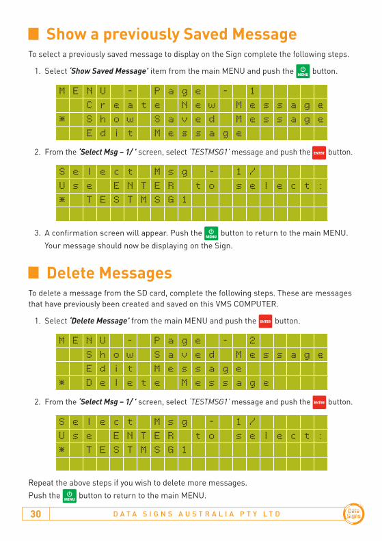
To select a previously saved message to display on the Sign complete the following steps.
1. Select ‘Show Saved Message’ item from the main MENU and push the button.
2. From the ‘Select Msg – 1/ ’ screen, select ‘TESTMSG1’ message and push the button.
3. A confirmation screen will appear. Push the button to return to the main MENU. Your message should now be displaying on the Sign.
S e l e c t M s g - 1 /
U s e E N T E R
t o s e l e c t :
* T E S T M S G 1
M E N U - P a g e - 1
C r e a t e N e w M e s s a g e
* S h o w S a v e d M e s s a g e
E d i t M e s s a g e
Show a previously Saved Message
To delete a message from the SD card, complete the following steps. These are messages that have previously been created and saved on this VMS COMPUTER.
1. Select ‘Delete Message’ from the main MENU and push the button.
2. From the ‘Select Msg – 1/ ’ screen, select ‘TESTMSG1’ message and push the button.
Repeat the above steps if you wish to delete more messages.Push the button to return to the main MENU.
M E N U - P a g e - 2
S h o w S a v e d M e s s a g e
E d i t M e s s a g e
* D e l e t e M e s s a g e
S e l e c t M s g - 1 /
U s e E N T E R
t o s e l e c t :
* T E S T M S G 1
Delete Messages

V M S O P E R A T I O N S M A N U A L 31
When this menu option is selected the Sign will display the last message sent from WebVMS™. Any message showing on the Sign from VMS COMPUTER will no longer be displayed.
Complete the following steps to resume the WebVMS™ message to display on the Sign.
1. Select the ‘Resume WebVMS MSG’ option from the MENU, then press .
The last WebVMS™ Message should now be displaying on the Sign.
This menu option lets you display messages created by WebVMS™ and previously sent to the Sign. Complete the following steps to run a WebVMS™ message on the Sign:
1. Select ‘Show WebVMS MSG’ option.
2. Select a WebVMS™ message to display on the Sign. Push the button to continue. A confirmation screen will appear and the WebVMS™ message should now be displayed on the Sign.
3. A confirmation screen will appear. Push the button to return to the main MENU. Your message should now be displaying on the Sign.
M E N U - P A G E
- 2
D e l e t e M e s s a g e
* S h o w W e b V M S M S G
R e s u m e W e b V M S
M S G
S e l e c t W e b V M S 0 1 /
M S G 1
* M S G 2
M S G 3
Show WebVMS™ Messages
M E N U - P A G E
- 2
S h o w
W e b V M S M S G
* R e s u m e W e b V M S M S G
Resume WebVMS™ Message

D A T A S I G N S A U S T R A L I A P T Y L T D32
This allows you to set the Security Settings between the VMS Computer and the Sign. A two-tier password scheme is provided for maximum security.
As a newly purchased unit, the pin is set to ‘0000’. If the pin is changed but you do not remember the new pin and it is entered incorrectly 5 times, the VMS COMPUTER will lock you out and display a challenge Code. Contact your Company’s WebVMS™ Administrator who can provide the code to reset the VMS Computer pin back to 0000.
Also, as a new purchased unit, the VMS Password is set to ‘123456’
V M S P A S S W O R D - 1 2 3 4 5 6
E n t e r p a s s w o r d f o r
t h i s s i g n :
( t h e n p r e s s
E N T E R )
If you have the incorrect VMS Password and you try to update the Sign you will be prompted to enter the correct password. The last saved VMS Password used by this VMS Computer is shown on the top line. You can simply push the button if this Password is correct, otherwise enter the Password first and then press .
Change Login PinYou can change the pin that you use to login to the VMS COMPUTER using the menu below.
V M S C O M P U T E R O P T N S -
* C h a n g e L o g i n P I N
Enable LoginIf the Login Pin is enabled, a 4-digit pin is required whenever the VMS COMPUTER starts up. This can be disabled using the Enable Login menu item if required.
Security Settings
Data Signs recommends leaving the Login Pin enabled for greater security and preventing unauthorised persons from putting messages onto your Sign.

V M S O P E R A T I O N S M A N U A L 33
Change VMS PasswordThis is the second-tier security password requirement for allowing messages to be sent to the Sign. If the VMS Password set on the VMS COMPUTER does not match the VMS Password on the Sign, then you will not be able to update messages.
To set the VMS Password on the VMS COMPUTER, complete the following steps:
1. Select the ‘Change VMS Pwd’ from the ‘VMS COMPUTER Optns’ menu.
2. Enter the VMS Password, (6 characters) for the Sign and then push the button.
V M S P A S S W O R D - 1 2 3 4 5 6
E n t e r p a s s w o r d f o r
t h i s s i g n :
( t h e n p r e s s
E N T E R )
If you have an incorrect VMS Password and you try to update the Sign you will be prompted to enter the correct password. The actual Sign ‘VMS Password’ can only be changed by your Company Administrator via WebVMS™.
Enable VMS Password Login
V M S C O M P U T E R O P T N S -
* V M S
P a s s w o r d E n t r y
If the VMS Password Entry is enabled, the VMS Password is required on Start-up.

D A T A S I G N S A U S T R A L I A P T Y L T D34
Below are more advanced menu items that are used for the VMS COMPUTER, these do not form part of the scope of this Quick Guide and additional information or ‘Training’ for this is available from Data Signs. Please contact Data Signs for more information.
M E N U - P a g e - 3
* V i e w S i g n S t a t u s
R a d a r s e n s i t v i t y
T i m e O f f s e t a d j
M E N U - P a g e - 4
* R a d a r O p t i o n s
T i m e r F u n c t i o n s
And via VMS ‘Computer Optns’ Menu;
S t a t u s B t n F u n c
S e t B r i g t n e s s L v l
• Ensure your Sign is switched on if you want to communicate from the VMS Computer to the Sign.
• WebVMS™ communication is currently in progress. Shown as Purple on the Status LED of your sign.
• Incorrect VMS Password. See Security Settings section.
• Ensure SD card is correctly inserted
Advanced Feature Menu options
If no response from Sign
© 2018 Data Signs Pty Ltd. All rights reserved | UNCONTROLLED WHEN PRINTED | MAN 0019A Issue 5 | Rev: 10-07-2018