vmware esx server · configuring for a lun 0 gatekeeper lun with symmetrix _____80 configuring emc...
TRANSCRIPT
SAN Configuration Guide
VMware ESX Server
V E R S I O N 2 . 5
VMware, Inc.
3145 Porter DrivePalo Alto, CA 94304www.vmware.com
Please note that you can always find the most up-to-date technical documentation on our Web site at http://www.vmware.com/support/.
The VMware Web site also provides the latest product updates.
Please note that you will always find the most up-to-date technical documentation on our Web site at http://www.vmware.com/support/. The VMwre Web site also provides the latest product updates.
Copyright © 1998-2005 VMware, Inc. All rights reserved. Protected by one or more of U.S. Patent Nos. 6,397,242,6,496,847, 6,704,925, 6,711,672, 6,725,289, 6,735,601, 6,785,886, 6,789,156 and 6,795,966; patents pending.VMware, the VMware “boxes” logo and design, Virtual SMP and VMotion are registered trademarks or trademarks of VMware, Inc. in the United States and/or other jurisdictions. Microsoft, Windows and Windows NT are registered trademarks of Microsoft Corporation. Linux is a registered trademark of Linus Torvalds. All other marks and names mentioned herein may be trademarks of their respective companies.Revision 20050502 Version: 2.5.1 Item: ESX-ENG-Q205-100
Table of Contents
3
Introduction ___________________________________________________7About This Manual _______________________________________________9
Intended Audience ____________________________________________9Document History _____________________________________________9Conventions __________________________________________________9Related Documentation _________________________________________9
VMware ESX Server Overview ___________________________________ 11System Architecture _____________________________________________12
Virtualization Capabilities _______________________________________12Service Console ______________________________________________15
Virtualization at a Glance _________________________________________18Software Compatibility ___________________________________________19
Storage Area Network Concepts _________________________________ 21Introducing SANs _______________________________________________22
SAN Components ____________________________________________22How a SAN Works ____________________________________________23
SAN Components _______________________________________________25Host Components ____________________________________________25Fabric Components ___________________________________________26Storage Components __________________________________________27
SAN Ports and Port Naming _______________________________________28Understanding Storage Arrays _____________________________________29
Storage Array Components _____________________________________29Accessing Storage Arrays _______________________________________30RAID _______________________________________________________31RAID Levels _________________________________________________32Applications of RAID Configurations ______________________________36
Performance Aspects of a SAN _____________________________________37Server Performance ___________________________________________37Storage Array Performance _____________________________________37
SAN Design Issues _______________________________________________39Application Requirements Analysis _______________________________39Mapping Requirements to Resources _____________________________39Designing for High Availability ___________________________________40
www.vmware.com4
Optimizing Backup ___________________________________________41Planning for Disaster Recovery ___________________________________41Designing Extensible SANs _____________________________________42Investigating SAN Interface Options ______________________________42
SAN Topologies ________________________________________________43High Availability Topology ______________________________________43Zoning _____________________________________________________44Fault Tolerance Topology _______________________________________45
SAN Installation Issues ___________________________________________47SAN Backup Considerations _______________________________________48Booting from a SAN _____________________________________________50Clustering _____________________________________________________51References for Information on SANs _________________________________52ESX Server Systems and Storage Area Networks _______________________53
Host Bus Adapters ____________________________________________53Storage Arrays _______________________________________________53Booting from the SAN _________________________________________54Clustering with ESX Server ______________________________________54Latest Information on SAN Support for ESX _________________________55Important Note ______________________________________________55
ESX Server SAN Requirements __________________________________ 57General ESX Server SAN Requirements _______________________________58ESX Server Boot from SAN Requirements _____________________________60
Hardware Requirements for Booting from SAN ______________________60SAN Configuration Requirements for Booting from SAN _______________60ESX Server Configuration Requirements for Booting from SAN __________61ESX Server SAN requirements for Booting from SAN __________________61
ESX Server MSCS Clustering Requirements ___________________________63
Setting Up HBAs for SAN with ESX Server _________________________ 65Configuring Your QLogic HBA BIOS _________________________________66Configuring the Emulex HBA BIOS __________________________________69
Setting Up SAN Storage Devices with ESX Server ___________________ 71Configuring IBM TotalStorage (FAStT) Storage Systems for Clustering _______73
Configuring the Hardware for SAN Failover with FAStT Storage Servers ___74Verifying the Storage Processor Port Configuration ___________________74Disabling AVT ________________________________________________75
5
Configuring Storage Processor Sense Data _________________________75Verifying Multipath Information __________________________________76Resetting Persistent Bindings ____________________________________77Configuring LUN Reset _________________________________________78
Configuring EMC Symmetrix Storage Systems _________________________80Configuring for a LUN 0 Gatekeeper LUN with Symmetrix ______________80
Configuring EMC CLARiiON Storage Systems __________________________82Configuring Dell/EMC Fibre Channel Storage Systems ___________________83Configuring HP StorageWorks Storage Systems ________________________84
Preparing Your SAN for Booting Your ESX Server System ____________ 87Preparing to Install for Boot From SAN _______________________________88Setting Up a Boot From SAN Path ___________________________________90
Setting Path Policies ___________________________________________90Setting Up /boot on /dev/sda ___________________________________90
Planning LUN Visibility for QLogic or Emulex HBAs ______________________93Adding a New LUN ___________________________________________93Scanning for Devices and LUNs __________________________________93Running cos-rescan.sh on Lowest Numbered HBA First _______________94Configuring LUN Reset _________________________________________94How LUNs Are Labeled ________________________________________95
Configuring VMFS Volumes on SANs ________________________________96Maximum Number of VMFS Volumes _____________________________96
Installing ESX Server on Storage Area Networks (SANs) _____________ 99Preparing to Install ESX Server with SAN _____________________________100Installation Options ____________________________________________101Changing VMkernel Configuration Options for SANs ___________________102
Detecting All LUNs ___________________________________________102Checking LUN Status _________________________________________103
Post-Boot ESX Server SAN Considerations _______________________ 105Reviewing LUN Status ___________________________________________106Failover Expectations ___________________________________________107Viewing Failover Paths Connections ________________________________108

www.vmware.com6
C H A P T E R 1
7
Introduction
The VMware ESX Server SAN Configuration Guide allows you to use your ESX Server system with a Storage Area Network (SAN). The manual includes configuration information and requirements for:
• Using ESX Server with a SAN:
This allows you to use shared external storage to enhance the manageability and availability of your ESX Server virtual machines.
• Enabling your ESX Server system to boot from a LUN on a SAN:
This allows your ESX Server system to run on a diskless server and greatly enhances support for common blade and rack mount configurations.
• Enabling virtual machine clustering with SAN:
This allows you to share storage between multiple ESX Server machines and provide failover services for the virtual machines in your clusters.
www.vmware.com8
VMware ESX Server SAN Configuration Guide
Background information for the use of ESX Server with a SAN is provided in:
• Chapter 2, "VMware ESX Server Overview" on page 11
• Chapter 3, "Storage Area Network Concepts" on page 21
Information about requirements is in:
• Chapter 4, "ESX Server SAN Requirements" on page 57
The following chapters discuss configuration of SAN components for use with ESX Server systems:
• Chapter 5, "Setting Up HBAs for SAN with ESX Server" on page 65
• Chapter 6, "Setting Up SAN Storage Devices with ESX Server" on page 71
• Chapter 7, "Preparing Your SAN for Booting Your ESX Server System" on page 87
The installation of ESX Server on a SAN is discussed in:
• Chapter 8, "Installing ESX Server on Storage Area Networks (SANs)" on page 99
Some considerations for the effective operation of ESX Server systems on a SAN once it has been installed and started are presented in:
• Chapter 9, "Post-Boot ESX Server SAN Considerations" on page 105
C H A P T E R 1 Introduction
9
About This ManualThis manual, the VMware ESX Server SAN Configuration Guide, describes the general requirements, architectural issues, configuration considerations, and steps required for using your ESX Server system with SAN devices.
Intended AudienceThis manual is intended for ESX Server system administrators and SAN administrators who wish to configure an ESX Server system for use in a SAN scenario.
This manual assumes you have a working knowledge of ESX Server, Fibre Channel host bus adapters (HBAs), logical unit number (LUN) mapping, and the SAN devices you intend to use with the ESX Server system.
Document HistoryThis manual is revised with each release of the product or when deemed necessary. A revised version can contain minor or major changes.
ConventionsThis manual uses the following conventions:
Related DocumentationSee the VMWare ESX Server Raw Device Mapping Guide for related information. See www.vmware.com/pdf/esx25_rawdevicemapping.pdf
Download an up-to-date VMware ESX Server SAN Compatibility List from the VMware Web site at //www.vmware.com/pdf/esx_SAN_guide.pdf.
Release Date Description
Release 2.5.1 May 2005 PDF on Web
First Release 2.5 December 2004 PDF on Web
Style Purpose
blue (online only) Cross references, links
Courier Commands, filenames, directories, paths, user input
Semi-Bold Interactive interface objects, keys, buttons
Bold Items of highlighted interest, terms
Italic Variables, parameters
italic Web addresses

www.vmware.com10
VMware ESX Server SAN Configuration Guide
C H A P T E R 2
11
VMware ESX Server Overview
Using VMware ESX Server effectively with storage area networks requires a working knowledge of ESX Server systems. This chapter presents an overview of the basic concepts behind ESX Server for SAN administrators not yet familiar with ESX server systems in the following sections:
• System Architecture on page 12
• Virtualization at a Glance on page 18
• Software Compatibility on page 19
For in-depth information on VMware ESX Server, see the latest ESX Server documentation, which is available on the VMware Web site at www.vmware.com/support/pubs/esx_pubs.html.
Additional technical information, covering such topics as hardware compatibility, is available at www.vmware.com/support/resources/esx_resources.html.

www.vmware.com12
VMware ESX Server SAN Configuration Guide
System ArchitectureThe ESX Server core architecture allows administrators to allocate hardware resources to multiple workloads in fully isolated environments called virtual machines.
An ESX Server system has the following key components:
• VMware virtualization layer — provides the idealized hardware environment and virtualization of underlying physical resources to the virtual machines. See Virtualization Capabilities on page 12.
• Service Console — gives access to the resource manager, which enables partitioning and guaranteed delivery of CPU, memory, network bandwidth, and disk bandwidth to each virtual machine. Also provides bootstrapping and other services to the ESX Server system. See Service Console on page 15.
• Hardware interface components—include device drivers, which enable hardware-specific service delivery while hiding hardware differences from other parts of the system.
Virtualization CapabilitiesThe VMware virtualization layer brings hardware virtualization to the standard Intel server platform and is common among VMware desktop and server products. This layer provides a consistent platform for development, testing, delivery, and support of application workloads.
Each virtual machine runs its own operating system (the guest operating system) and applications. Virtual machines can talk to each other only by way of networking mechanisms similar to those used to connect separate physical machines.
The VMware virtual machine offers complete hardware virtualization. The guest operating system and applications running on a virtual machine can never directly
C H A P T E R 2 VMware ESX Server Overview
13
determine which physical resources they are accessing (such as which CPU they are running on in a multiprocessor system, or which physical memory is mapped to their pages).
The virtualization layer provides an idealized physical machine that is isolated from other virtual machines on the system. It provides the virtual devices that map to shares of specific physical devices. These devices include virtualized CPU, memory, I/O buses, network interfaces, storage adapters and devices, human interface devices, BIOS, and others.
This isolation leads many users of VMware software to build internal firewalls or other network isolation environments, allowing some virtual machines to connect to the outside while others are connected only by way of virtual networks through other virtual machines.
The various types of virtualization provided by the ESX Server architecture are discussed in the following sections:
• CPU Virtualization on page 13
• Memory Virtualization on page 13
• Disk Virtualization on page 14
• Network Virtualization on page 14
• Private Virtual Ethernet Networks on page 14
CPU VirtualizationEach virtual machine appears to run on its own CPU (or a set of CPUs), fully isolated from other virtual machines. Registers, translation lookaside buffer, and other control structures are maintained separately for each virtual machine.
Most instructions are directly executed on the physical CPU, allowing compute-intensive workloads to run at near-native speed. Privileged instructions are performed safely by the patented and patent-pending technology in the virtualization layer.
Memory VirtualizationA contiguous memory space is visible to each virtual machine; however, the allocated physical memory may not be contiguous. Instead, noncontiguous physical pages are remapped and presented to each virtual machine. Some of the physical memory of a virtual machine may in fact be mapped to shared pages, or to pages that are unmapped or swapped out. ESX Server performs this virtual memory management without knowledge of the guest operating system and without interfering with its memory management subsystem.
www.vmware.com14
VMware ESX Server SAN Configuration Guide
Disk VirtualizationEach virtual disk appears as if it were a SCSI drive connected to a SCSI adapter. Whether the actual physical disk device is being accessed through SCSI, RAID, or Fibre Channel controllers is transparent to the guest operating system and to applications running on the virtual machine.
Support of disk devices in ESX Server is an example of the hardware independence provided for the virtual machines. Some or all of a physical disk device volume may be presented to a virtual machine as a virtual disk.
This abstraction makes virtual machines more robust and more transportable. The file that encapsulates a virtual disk is identical no matter what underlying controller or disk drive is used. There is no need to worry about the variety of potentially destabilizing drivers that may need to be installed on guest operating systems.
VMware ESX Server can be used especially effectively with storage area networks (SANs). Through Fibre Channel host bus adapters (HBAs), an ESX Server system can be connected to a SAN and see the disk arrays on the SAN in any manner deemed appropriate for the particular virtual machine.
The HBAs and storage devices that are supported by ESX Server systems are discussed in Chapter 4, "ESX Server SAN Requirements" on page 57 of this guide. In addition, Chapter 5, "Setting Up HBAs for SAN with ESX Server" on page 65 and Chapter 6, "Setting Up SAN Storage Devices with ESX Server" on page 71 provide information on configuring these SAN components.
Network VirtualizationYou may define up to four virtual network cards (VMnics) within each virtual machine. Each virtual network card has its own MAC address. Each card may also have its own IP address (or multiple addresses). Virtual network interfaces from multiple virtual machines may be connected to a virtual switch.
Each virtual switch may be configured as a purely virtual network with no connection to a physical LAN, or may be bridged to a physical LAN by way of one or more of the physical NICs on the host machine.
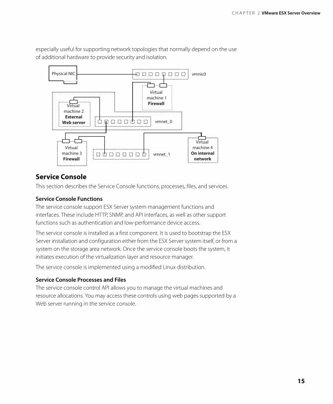
Private Virtual Ethernet Networks Private Virtual Ethernet Network (VMnet) connections can be used for high-speed networking between virtual machines, allowing private, cost-effective connections between virtual machines. The isolation inherent in their design makes them
C H A P T E R 2 VMware ESX Server Overview
15
especially useful for supporting network topologies that normally depend on the use of additional hardware to provide security and isolation.
Service ConsoleThis section describes the Service Console functions, processes, files, and services.
Service Console FunctionsThe service console support ESX Server system management functions and interfaces. These include HTTP, SNMP, and API interfaces, as well as other support functions such as authentication and low-performance device access.
The service console is installed as a first component. It is used to bootstrap the ESX Server installation and configuration either from the ESX Server system itself, or from a system on the storage area network. Once the service console boots the system, it initiates execution of the virtualization layer and resource manager.
The service console is implemented using a modified Linux distribution.
Service Console Processes and FilesThe service console control API allows you to manage the virtual machines and resource allocations. You may access these controls using web pages supported by a Web server running in the service console.
InternalNetwork Virtual
Machine
InternalNetwork Virtual
Machine
vmnic0NICPhysical NIC
vmnet_1
vmnet_0
Virtual machine 1Firewall Virtual
machine 2External
Web server
Virtual machine 3Firewall
Virtual machine 4
On internalnetwork
www.vmware.com16
VMware ESX Server SAN Configuration Guide
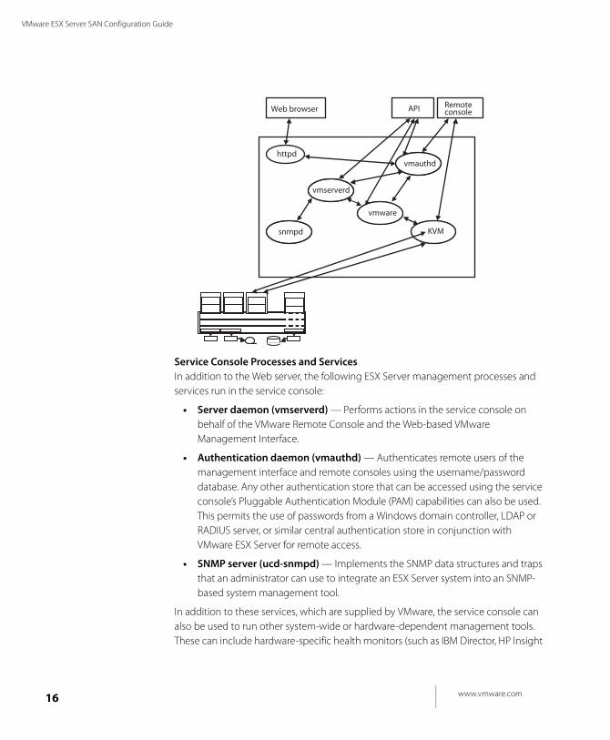
Service Console Processes and Services In addition to the Web server, the following ESX Server management processes and services run in the service console:
• Server daemon (vmserverd) — Performs actions in the service console on behalf of the VMware Remote Console and the Web-based VMware Management Interface.
• Authentication daemon (vmauthd) — Authenticates remote users of the management interface and remote consoles using the username/password database. Any other authentication store that can be accessed using the service console’s Pluggable Authentication Module (PAM) capabilities can also be used. This permits the use of passwords from a Windows domain controller, LDAP or RADIUS server, or similar central authentication store in conjunction with VMware ESX Server for remote access.
• SNMP server (ucd-snmpd) — Implements the SNMP data structures and traps that an administrator can use to integrate an ESX Server system into an SNMP-based system management tool.
In addition to these services, which are supplied by VMware, the service console can also be used to run other system-wide or hardware-dependent management tools. These can include hardware-specific health monitors (such as IBM Director, HP Insight
httpd
vmserverd
snmpd
vmauthd
API RemoteconsoleWeb browser
vmwarevmware
mksKVM
C H A P T E R 2 VMware ESX Server Overview
17
Manager, and others), full-system backup and disaster recovery software, and clustering and high availability products.
The server and virtual machine resources and configuration attributes that are available through the SNMP and HTTP interfaces are visible through a file system in the service console. Users logged on to the service console with sufficient permissions can examine or modify the files in this /proc/vmware name space or can use them as a point of integration for home-grown or commercial scripts and management tools.
www.vmware.com18
VMware ESX Server SAN Configuration Guide
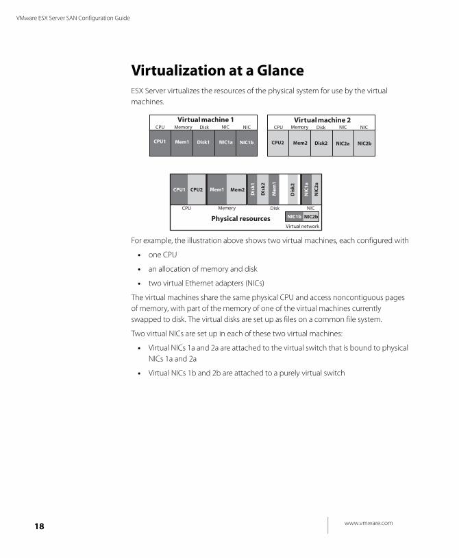
Virtualization at a GlanceESX Server virtualizes the resources of the physical system for use by the virtual machines.
For example, the illustration above shows two virtual machines, each configured with
• one CPU
• an allocation of memory and disk
• two virtual Ethernet adapters (NICs)
The virtual machines share the same physical CPU and access noncontiguous pages of memory, with part of the memory of one of the virtual machines currently swapped to disk. The virtual disks are set up as files on a common file system.
Two virtual NICs are set up in each of these two virtual machines:
• Virtual NICs 1a and 2a are attached to the virtual switch that is bound to physical NICs 1a and 2a
• Virtual NICs 1b and 2b are attached to a purely virtual switch
Virtual machine 1 Virtual machine 2
Memory Disk
Physical resources
NIC
Virtual network
Memory Memory DiskDisk NICNICNICNIC
CPU
CPU CPU
CPU1
CPU1
Mem1
Mem1
Mem
1
Disk1
Dis
k1
NIC1a
NIC
1a
NIC1b
NIC1b
CPU2
CPU2
Mem2
Mem2
Disk2
Dis
k2
Dis
k2
NIC2a
NIC
2a
NIC2b
NIC2b
C H A P T E R 2 VMware ESX Server Overview
19
Software CompatibilityIn the VMware ESX Server architecture, guest operating systems interact only with the standard x86-compatible virtual hardware presented by the virtualization layer. This allows VMware to support any x86-compatible operating system.
In practice VMware supports a subset of x86-compatible operating systems that are tested throughout the product development cycle. VMware documents the installation and operation of these guest operating systems and trains its technical personnel in their support.
Application compatibility is not an issue once operating system compatibility with the virtual hardware is established because applications interact only with their guest operating system, not with the underlying virtual hardware.

www.vmware.com20
VMware ESX Server SAN Configuration Guide
C H A P T E R 3
21
Storage Area Network Concepts
This chapter presents an overview of storage area network concepts in these sections:
• Introducing SANs on page 22
• SAN Components on page 25
• SAN Ports and Port Naming on page 28
• Understanding Storage Arrays on page 29
• Performance Aspects of a SAN on page 37
• SAN Design Issues on page 39
• SAN Topologies on page 43
• SAN Installation Issues on page 47
• SAN Backup Considerations on page 48
• Booting from a SAN on page 50
• Clustering on page 51
• References for Information on SANs on page 52
• ESX Server Systems and Storage Area Networks on page 53
www.vmware.com22
VMware ESX Server SAN Configuration Guide
Introducing SANsA storage area network (SAN) is a specialized high-speed network of storage devices and computer systems (also referred to as servers, hosts, or host servers). Currently, most SANs use the Fibre Channel protocol.
A storage area network presents shared pools of storage devices to multiple servers. Each server can access the storage as if it were directly attached to that server. The SAN makes it possible to move data between various storage devices, share data between multiple servers, and back up and restore data rapidly and efficiently. In addition, a properly configured SAN provides robust security, which facilitates both disaster recovery and business continuance.
Components of a SAN can be grouped closely together in a single room or connected over long distances. This makes SAN a feasible solution for businesses of any size: the SAN can grow easily with the business it supports.
SAN ComponentsIn its simplest form, a SAN is a number of servers attached to a storage array using a switch. The following components are involved:
• SAN Switches — Specialized switches called SAN switches are at the heart of the typical SAN. Switches provide capabilities to match the number of host SAN connections to the number of connections provided by the storage array. Switches also provide path redundancy in the event of a path failure from host server to switch or from storage array to switch.
• Fabric — When one or more SAN switches are connected, a fabric is created. The fabric is the actual network portion of the SAN. A special communications protocol called Fibre Channel (FC) is used to communicate over the entire network. Multiple fabrics may be interconnected in a single SAN, and even for a simple SAN it is not unusual to be composed of two fabrics for redundancy.
• Connections: HBA and Controllers — Host servers and storage systems are connected to the SAN fabric through ports in the fabric. A host connects to a fabric port through a Host Bus Adapter (HBA), and the storage devices connect to fabric ports through their controllers.
Each server may host numerous applications that require dedicated storage for applications processing. Servers need not be homogeneous within the SAN environment.
C H A P T E R 3 Storage Area Network Concepts
23
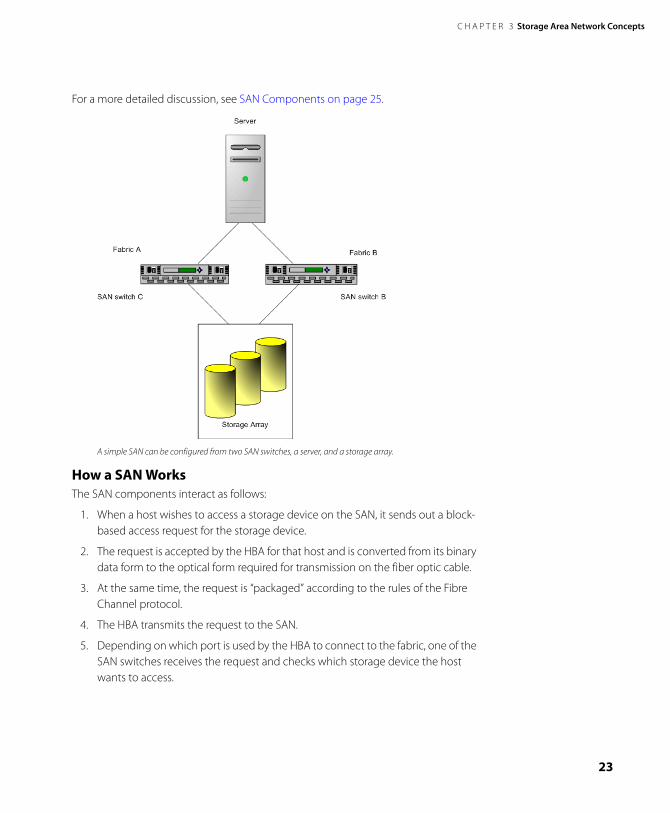
For a more detailed discussion, see SAN Components on page 25.
A simple SAN can be configured from two SAN switches, a server, and a storage array.
How a SAN WorksThe SAN components interact as follows:
1. When a host wishes to access a storage device on the SAN, it sends out a block-based access request for the storage device.
2. The request is accepted by the HBA for that host and is converted from its binary data form to the optical form required for transmission on the fiber optic cable.
3. At the same time, the request is “packaged” according to the rules of the Fibre Channel protocol.
4. The HBA transmits the request to the SAN.
5. Depending on which port is used by the HBA to connect to the fabric, one of the SAN switches receives the request and checks which storage device the host wants to access.
www.vmware.com24
VMware ESX Server SAN Configuration Guide
From the host perspective, this appears to be a specific disk, but it is actually just a logical device that corresponds to some physical device on the SAN. It is up to the switch to determine which physical device has been made available to the host for its targeted logical device.
6. Once the switch has determined the appropriate physical device, it passes the request to the appropriate storage device.
The remaining sections of this chapter provide additional details and information about the components of the SAN and how they interoperate. These sections also present general information on the different ways in which a SAN can be configured, and the considerations to be made when designing a SAN configuration.
C H A P T E R 3 Storage Area Network Concepts
25
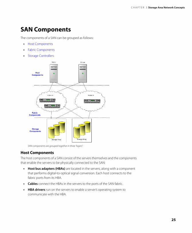
SAN ComponentsThe components of a SAN can be grouped as follows:
• Host Components
• Fabric Components
• Storage Controllers
SAN components are grouped together in three “layers”.
Host ComponentsThe host components of a SAN consist of the servers themselves and the components that enable the servers to be physically connected to the SAN:
• Host bus adapters (HBAs) are located in the servers, along with a component that performs digital-to-optical signal conversion. Each host connects to the fabric ports from its HBA.
• Cables connect the HBAs in the servers to the ports of the SAN fabric.
• HBA drivers run on the servers to enable a server’s operating system to communicate with the HBA.
www.vmware.com26
VMware ESX Server SAN Configuration Guide
Fabric ComponentsAll hosts connect to the storage devices on the SAN through the fabric of the SAN. The actual network portion of the SAN is formed by the fabric components.
The fabric components of the SAN can include any or all of the following:
• Data Routers
• SAN Hubs
• SAN Switches
• Cables
Data Routers Data routers provide intelligent bridges between the Fibre Channel devices in the SAN and the SCSI devices. Specifically, servers in the SAN can access SCSI disk or tape devices in the SAN through the data routers in the fabric layer.
SAN Hubs SAN hubs were used in early SANs and were the precursors to today’s SAN switches. A SAN hub connects Fibre Channel devices in a loop (called a Fibre Channel Arbitrated Loop, or FC-AL). Although some current SANs may still be based on fabrics formed by hubs, the most common use today for SAN hubs is for sharing tape devices, with SAN switches taking over the job of sharing disk arrays.
SAN Switches SAN switches are at the heart of most SANs. SAN Switches can connect both servers and storage devices, and thus provide the connection points for the fabric of the SAN.
• For smaller SANs, the standard SAN switches are called modular switches and can typically support 8 or 16 ports (though some 32-port modular switches are beginning to emerge). Sometimes modular switches are interconnected to create a fault-tolerant fabric.
• For larger SAN fabrics, director-class switches provide a larger port capacity (64 to 128 ports per switch) and built-in fault tolerance.
The type of SAN switch, its design features, and its port capacity all contribute its overall capacity, performance, and fault tolerance. The number of switches, types of switches, and manner in which the switches are interconnected define the topology of the fabric. See SAN Topologies on page 43 for a closer look at this topic.
Cables SAN cables are special fiber optic cables that are used to connect all of the fabric components. The type of SAN cable and the fiber optic signal determine the
C H A P T E R 3 Storage Area Network Concepts
27
maximum distances between SAN components, and contribute to the total bandwidth rating of the SAN.
Storage ComponentsThe storage components of the SAN are the disk storage arrays and the tape storage devices.
Storage arrays (groups of multiple disk devices) are the typical SAN disk storage device. They can vary greatly in design, capacity, performance, and other features.
Tape storage devices form the backbone of the SAN backup capabilities and processes.
• Smaller SANs may just use high-capacity tape drives. These tape drives vary in their transfer rates and storage capacities. A high-capacity tape drive may exist as a stand-alone drive, or it may be part of a tape library.
• A tape library consolidates one or more tape drives into a single enclosure. Tapes can be inserted and removed from the tape drives in the library automatically with a robotic arm. Many tape libraries offer very large storage capacities—sometimes into the petabyte (PB) range. Typically, large SANs, or SANs with critical backup requirements, configure one or more tape libraries into their SAN.
See Understanding Storage Arrays on page 29 for further discussion of disk storage devices in a SAN.
www.vmware.com28
VMware ESX Server SAN Configuration Guide
SAN Ports and Port NamingThe points of connection from devices to the various SAN components are called SAN ports. Fabric ports are the SAN ports that serve as connection points to the switches, hubs, or routers that comprise the fabric of the SAN. All ports in a SAN are Fibre Channel ports.
Each component in a SAN — each host, storage device, and fabric component (hub, router, or switch) — is called a node, and each node may have one or more ports defined for it.
Ports can be identified in a number of ways:
• Port_ID — Within the SAN, each port has a unique Port_ID that serves as the Fibre Channel address for the port. This enables routing of data through the SAN to that port.
• WWPN — A unique World Wide Port Name (WWPN) also identifies each port in a SAN. The WWPN is a globally unique identifier for the port that allows certain applications to access it from outside the SAN.
• PortType_PortMode—In another port naming convention, the port name consists of the type of port it is (that is, on which type of SAN component the port is physically located) and how the port is used (its logical operating mode). Using that convention, the port’s name can change as it goes in and out of use on the SAN.
For example, an unused port on a SAN Fibre Channel switch is initially referred to as a G_Port. If a host server is plugged into it, the port becomes a port into the fabric, so it becomes an F_Port. However, if the port is used instead to connect the switch to another switch (an inter-switch link), it becomes an E_Port.
In-depth information on SAN ports can be found at www.snia.org, the Web site of the Storage Networking Industry Association.
C H A P T E R 3 Storage Area Network Concepts
29
Understanding Storage ArraysThis section provides conceptual information on storage arrays by discussing the following sections:
• Storage Array Components
• Accessing Storage Arrays on page 30
• RAID on page 31
• RAID Levels on page 32
• Applications of RAID Configurations on page 36
Storage Array ComponentsA storage array, a key component of the SAN, consists of the following components, discussed in this section:
• Storage Controllers
• Control Systems
• Drives
Storage ControllersStorage controllers provide front-side host attachments to the storage devices from the servers, either directly or through a switch. Host servers need to have host bus adapters (HBAs) that conform to the protocol supported by the storage controller. In most cases, this is the Fibre Channel protocol.
Controllers also provide internal access to the drives, which are normally connected in loops. This back-end loop technology employed by the storage controller provides several benefits:
• High-speed access to the drives
• Ability to add more drives to the loop
• Redundant access to a single drive from multiple loops (when drives are dual-ported and attached to two loops)
Control SystemsControllers are managed by a built-in control system that accepts read and write requests from the host servers. The controllers process those requests to access data on the drives. The control system is also responsible for the setup, maintenance, and administration of user storage. The control system is usually accessible through either a graphical or command-line interface.
www.vmware.com30
VMware ESX Server SAN Configuration Guide
Storage Array Control systems provide the ability to define storage objects (LUNs) for host servers, change their operating characteristics (such as performance, capacity, and data protection levels), and expand the capacity of the storage array for improved operating characteristics.
DrivesMost storage arrays have disk drives of varying capacities and use one of three protocols:
• Small Computer System Interface (SCSI) — The SCSI standard was the first universal standard protocol for interfacing storage to servers through host bus adapters. Although it was originally intended for use with small computer systems, SCSI was quickly adopted and spread to meet most storage interface requirements.
The SCSI interface is still in use today, but for storage area networks the SCSI protocol is effectively embedded in Fibre Channel protocol.
• Fibre Channel (FC) — Fibre Channel (FC) is the storage interface protocol used for today’s SANs. FC was developed through an industry consortium as a protocol for transferring data between two ports on a serial I/O bus cable at high speeds. Fibre Channel supports point-to-point, arbitrated loop, and switched topologies, with the switched topology as the basis for current SANs.
• Serial ATA (SATA) — Serial ATA (SATA) is the updated version of the older ATA (or IDE) interface used for low-cost disk drives. Some storage array control systems allow the mixing of FC and SATA drive technologies, providing the ability to balance performance and cost objectives.
Accessing Storage ArraysStorage arrays rarely provide direct access to individual drives for host access. The storage array uses RAID technology to group a set of drives (see RAID on page 31). This results in high performance and higher levels of data protection.
Storage arrays may dynamically change the performance and data protection levels by changing the RAID levels underlying the logical LUNs presented to the host servers. Capacity expansion may also be available if the storage array control system has the ability to dynamically add new drives to the storage array.
Most storage arrays provide additional data protection and replication features such as snapshots, internal copies, and remote mirroring. Snapshots are point-in-time copies of a LUN. Snapshots are used as backup sources for the overall backup procedures defined for the storage array.
C H A P T E R 3 Storage Area Network Concepts
31
Internal copies allow data movement from one LUN to another for an additional copy for testing. Remote mirroring provides constant synchronization between LUNs on one storage array and a second, independent (usually remote) storage array.
LUNs Logical Unit Numbers (LUNs) were originally defined in the SCSI specifications to indicate a distinct addressable unit, (typically a disk drive). Today, the term LUN refers to a single unit of storage. Depending on the host system environment, this may also be known as a volume or a logical drive.
In simple systems that provide RAID capability, a RAID group is equivalent to a single LUN. A host server sees this LUN as a single simple storage unit that is available for access by the server.
In advanced storage arrays, RAID groups can have one or more LUNs created for access by one or more host servers. The ability to create more than one LUN from a single RAID group provides fine granularity to the storage creation process— you are not limited to the total capacity of the entire RAID group for a single LUN.
Performance TuningPerformance tuning of the storage array allows for:
• Adjustment of the cache policies for the various storage objects
• Ability to define and change the basic block size and stripe width for the optimization of I/O throughput from the host server application
• Balancing of storage objects across the available host-side channels and the back-end internal loops for optimal throughput and latency
RAIDThis section describes RAID terminology and control functions.
Introduction to RAIDRAID (Redundant Array of Independent Drives) was developed as a means to use small, independent drives to provide capacity, performance, and redundancy.
Using specialized algorithms, several drives are grouped together to provide common pooled storage. These RAID algorithms, commonly known as RAID levels, define the characteristics of the particular grouping. In general, the various RAID levels provide variations of three basic parameters:
• Capacity is simply the number of drives in the defined RAID group that contain user data. There are also one or more drives that contain overhead information
www.vmware.com32
VMware ESX Server SAN Configuration Guide
for the RAID controller, or are copies of other drive data, that do not count towards the total capacity.
• Performance varies with the RAID level of the drive group. This is a function of the number of simultaneous I/Os that can be processed by that RAID group. It is not always a function of the number of drives.
• Redundancy provides the ability to sustain one or more drive failures while still providing basic I/O functions to the RAID group. This is normally accomplished through the use of mirrored drives or parity information that is available to reconstruct data missing from a failed drive.
RAID Control FunctionsRAID control functions begin with LUN definitions for server access. LUNs are defined from RAID groups.
During the life of a LUN, the RAID control system may do any or all of the following:
• Expand the size of the LUN for additional capacity.
• Change the RAID-level for performance tuning.
• Move the LUN to another group to balance the load between groups.
The capacity of a RAID group is simply the total amount of storage provided by the designated number of drives in the RAID group, minus the overhead of the selected RAID level.
RAID LevelsThe most commonly used RAID levels are:
• RAID-0
• RAID-1
• RAID-5
• RAID0+1
• RAID1+0. (RAID 10)
Note: Additional RAID-levels are defined as extensions to these basic levels, but they vary from one implementation to the next and are not widely used.
C H A P T E R 3 Storage Area Network Concepts
33
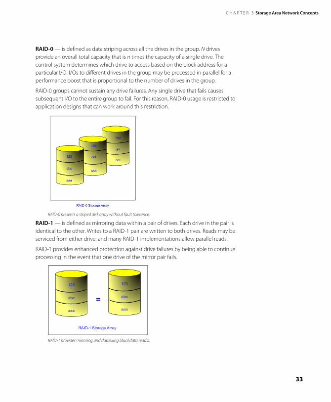
RAID-0 — is defined as data striping across all the drives in the group. N drives provide an overall total capacity that is n times the capacity of a single drive. The control system determines which drive to access based on the block address for a particular I/O. I/Os to different drives in the group may be processed in parallel for a performance boost that is proportional to the number of drives in the group.
RAID-0 groups cannot sustain any drive failures. Any single drive that fails causes subsequent I/O to the entire group to fail. For this reason, RAID-0 usage is restricted to application designs that can work around this restriction.
RAID-0 presents a striped disk array without fault tolerance.
RAID-1 — is defined as mirroring data within a pair of drives. Each drive in the pair is identical to the other. Writes to a RAID-1 pair are written to both drives. Reads may be serviced from either drive, and many RAID-1 implementations allow parallel reads.
RAID-1 provides enhanced protection against drive failures by being able to continue processing in the event that one drive of the mirror pair fails.
RAID-1 provides mirroring and duplexing (dual data reads).
www.vmware.com34
VMware ESX Server SAN Configuration Guide
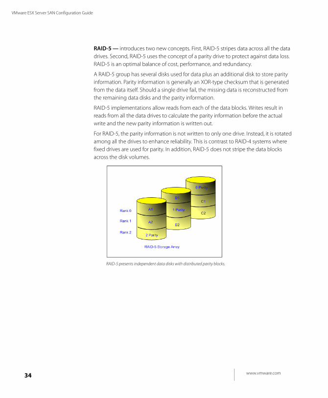
RAID-5 — introduces two new concepts. First, RAID-5 stripes data across all the data drives. Second, RAID-5 uses the concept of a parity drive to protect against data loss. RAID-5 is an optimal balance of cost, performance, and redundancy.
A RAID-5 group has several disks used for data plus an additional disk to store parity information. Parity information is generally an XOR-type checksum that is generated from the data itself. Should a single drive fail, the missing data is reconstructed from the remaining data disks and the parity information.
RAID-5 implementations allow reads from each of the data blocks. Writes result in reads from all the data drives to calculate the parity information before the actual write and the new parity information is written out.
For RAID-5, the parity information is not written to only one drive. Instead, it is rotated among all the drives to enhance reliability. This is contrast to RAID-4 systems where fixed drives are used for parity. In addition, RAID-5 does not stripe the data blocks across the disk volumes.
RAID-5 presents independent data disks with distributed parity blocks.

C H A P T E R 3 Storage Area Network Concepts
35
RAID-0+1— is an extension of RAID-0. It is defined as two groups of RAID-0 (striped) disks where each RAID-0 group mirrors the other.
Basic I/O processing to a RAID0+1 group allows two simultaneous I/O operations, one to each group. RAID0+1 groups can sustain only a single drive failure. The first drive failure causes a failure to the RAID-0 group to which the failed drive belongs. A second drive failure in the remaining RAID-0 group causes a total outage.
RAID 0+! provides high data transfer performance from its mirrored striped volumes.
RAID-1+ 0 — is an extension of RAID-1 (mirroring). A RAID1+0 group (also known as RAID-10) consists of multiple RAID-1 pairs (mirrors) to form an extended RAID-0 (striped) group. Basic I/O processing allows one I/O request per RAID-1 pair. Drive failures can occur per pair up to the maximum number of RAID-1 pairs.
RAID-10 provides very high reliability with high performance.

www.vmware.com36
VMware ESX Server SAN Configuration Guide
Applications of RAID ConfigurationsA storage array may contain several hundred drives that are grouped into multiple RAID groups. There may be one or more RAID-0, RAID-1, RAID-5, and RAID10 groups. RAID-0 and RAID-1 groups may be assigned to low capacity host server applications with varying redundancy requirements.
RAID-10 groups may have one or more LUNs defined for high-performance host server applications. For applications with fewer performance and redundancy requirements, RAID-5 LUNs are available.
At any time when requirements change, the RAID groups may be dynamically expanded to add more capacity to the RAID group and, in turn, each of the LUNs may also be expanded in capacity.
Note that dynamic LUN capacity expansion is only available to a host operating system if the operating system supports this feature.
RAID levels of groups may be changed to accommodate performance and redundancy requirements. For example, a RAID-5 group may change to a RAID-10 level to provide more performance and data protection.
While not all storage arrays provide this level of flexibility, those that do provide the tools to meet future performance and redundancy requirements.
C H A P T E R 3 Storage Area Network Concepts
37
Performance Aspects of a SANThe two major factors for optimizing a typical SAN environment are server performance and storage array performance. Although the SAN fabric components (particularly the SAN switches) do contribute to the overall performance of the SAN, they are minor contributors because of their low latencies relative to servers and storage arrays.
Server PerformanceEnsuring optimal server performance requires looking at a number of factors. Each server application must have access to its designated storage with:
• High I/O throughput (number of I/Os per second)
• Fast data movement (megabytes per second)
• Minimal latency (response times)
To achieve this:
1. Place storage objects (LUNs) on RAID groups that provide the necessary performance levels.
2. Make sure that each server has a sufficient number of HBAs to allow maximum performance throughput for all the applications hosted on the server for the peak period. I/Os spread across multiple HBAs provide higher throughput and less latency for each application.
3. To provide redundancy in the event of an HBA failure, make sure the server has a minimum of two HBAs.
HBA paths to the storage array are logical, so I/O requests initiating from any server application should be able to take any HBA path through the switch to the storage array. To optimize this aspect of the server performance, the host server and operating system need to have their I/O subsystem provide load balancing across all HBAs to allow the maximum performance for all application I/O.
Overall, each server in the SAN should be continually tuned for optimal access to storage.
Storage Array PerformanceFrom a server access viewpoint, storage array connections are the paths to the storage objects for all applications. In most storage arrays, each connection is
www.vmware.com38
VMware ESX Server SAN Configuration Guide
assigned to an internal controller and a single controller manages all I/O requests in-bound on a storage array path.
The goal of load balancing server I/O requests to the storage array is to ensure that all controllers and their associated host server paths provide the required I/O performance in terms of throughput (I/Os per second, megabytes per second, or response times).
• Static load balancing. SAN storage arrays that provide only static load balancing require continual design and tuning over time to ensure that I/Os are load balanced across all storage array paths. This requires planning to distribute the LUNs among all the controllers to provide optimal load balancing. Close monitoring indicates when it is necessary to manually re-balance the LUN distribution.
Tuning statically balanced storage arrays is a matter of monitoring the specific performance statistics (such as I/Os per second, blocks per second, response time, and so forth) and distributing the LUN workload to spread the workload across all the controllers.
• Dynamic load balancing. Many high-end storage arrays provide dynamic load balancing at their controller level. Storage arrays that provide dynamic load balancing are easier to optimize for performance. Each LUN or group of LUNs has a policy-based set of rules for performance. Setting storage performance policy for each LUN allows the storage array to self-tune to these requirements.
C H A P T E R 3 Storage Area Network Concepts
39
SAN Design IssuesDesigning an optimal SAN for multiple applications and servers involves a balance of the performance, reliability, and capacity attributes of the SAN. Each application demands resources and access to storage provided by the SAN. The switches and storage arrays of the SAN must provide timely and reliable access for all competing applications. Design involves a number of tasks discussed in this section:
• Application Requirements Analysis
• Mapping Requirements to Resources
• Designing for High Availability
• Optimizing Backup
• Planning for Disaster Recovery
• Designing Extensible SANs
• Investigating SAN Interface Options
Application Requirements AnalysisApplication requirements vary over peak periods for I/Os per second, as well as bandwidth in megabytes per second. It is necessary to maintain fast response times consistently for each application. The storage arrays need to accommodate all server requests and to tune their resources to serve all requests in a timely manner.
A properly designed SAN must provide sufficient resources to process all I/O requests from all applications. The first step in designing an optimal SAN is to determine the storage requirements for each application in terms of:
• I/O performance (I/Os per second)
• bandwidth (megabytes per second)
• capacity (number of LUNs, and capacity per LUN)
• redundancy level (RAID-level)
• response times (average time per I/O)
• overall processing priority
Mapping Requirements to ResourcesAs the next step in the SAN design, you must design the storage array. Doing so involves mapping all of the defined storage requirements to the resources of the storage array. You assign LUNs to RAID groups based on capacity and redundancy
www.vmware.com40
VMware ESX Server SAN Configuration Guide
requirements, where each underlying RAID group provides a specific level of I/O performance, capacity, and redundancy.
If the number of required LUNs exceeds the ability of a particular RAID group to provide I/O performance, capacity, and response times, you must define an additional RAID group for the next set of LUNs. The goal here is to provide sufficient RAID group resources to support the requirements of one set of LUNs.
Overall, the storage arrays need to distribute the RAID groups across all internal channels and access paths to provide load-balancing of all I/O requests to meet performance requirements of I/Os per second and response times.
Peak Period ActivityThe SAN design should be based on peak-period activity and should consider the nature of the I/O within each peak period. You may find that additional storage array resource capacity is required to accommodate instantaneous peaks.
For example, a peak period may occur during noontime processing, characterized by several peaking I/O sessions requiring two, or even four, times the average for the entire peak period. Without additional resources, any I/O demands that exceed the capacity of a storage array result response times.
Designing for High AvailabilityAnother design concern is high availability for the SAN. To support high availability, a number of requirements must be met.
• Provide redundant access paths from the server to the storage array. At least two HBAs from each server are necessary to provide an alternate access path from the server to the SAN switch.
• Design the SAN switch with at least two paths to the storage array. If there are separate access paths to each internal controller in the storage array, additional paths are required. This ensures an alternate access path to each controller in the event that a single storage controller access path fails.
• Set up access path switching. Within the storage array there should be a mechanism to switch access paths in the event of an individual controller failure. The LUNs owned or controller by one controller should be switched to an alternate controller if this failure occurs.
Whether there’s a failure of an HBA in the server, a controller in the storage array, or simply a path in between failures, the server I/O processor and the storage array should communicate this failure, and indicate the new alternate path to all
C H A P T E R 3 Storage Area Network Concepts
41
components of the SAN. This allows all components to re-route all subsequent I/Os through the new path.
Optimizing BackupBackup is an important part of an operational SAN. When there are numerous applications that require periodic backups, the SAN can optimize this process by providing dedicated backup servers to assist the backup process.
Normally each server is responsible for its own backup procedures; however, SAN technology allows servers to be dedicated to providing this backup service for all applications servers in the SAN. These dedicated backup servers offload the processing from the applications servers and also take advantage of storage-based features to speed up the backup process.
For example, a storage array-based replication feature called snapshot creates a point-in-time copy of a LUN, which allows the backup to quickly create this point-in-time copy and eliminate copying the LUN. This LUN snapshot occurs in minutes and reduces the online copy time down by hours and days. In parallel, the backup program uses this point-in-time LUN snapshot as a source for its backup processing and eliminates the slow access of backing up the original LUN.
The use of storage array-based replication features provides an optimal method of accessing all applications server data for backup and recovery of the SAN. This method also avoids the proprietary nature of heterogeneous applications and servers in terms of backup solutions. This single method works across all applications and servers in the SAN.
Planning for Disaster RecoveryAn important consideration for the SAN environment is recovering from planned or unplanned contingencies. Whether these are human errors or natural disasters, the SAN should provide tools and resources to recover from these occurrences.
If an application, database, or server fails for any reason, there is an immediate need to recover the failed component, recover the data, and restart the application. The SAN must provide access to the data from an alternate server to start the data recovery process. This may require access to archived data for complete recovery processing. In the event that this process fails, mirrored copies of the data provide an alternative disaster recovery plan.
www.vmware.com42
VMware ESX Server SAN Configuration Guide
Designing Extensible SANsApplications, servers, and storage arrays change over time. The ability of a SAN design to adapt to changing requirements is dependent on specific features in each constituent component. For example:
• Adding servers to the SAN requires that the SAN switches have sufficient port capacities for the multiple host server HBA connections.
• SAN switches may expand capacity by adding additional ports or by linking to a new SAN switch.
• Expansion of the storage array may involve adding capacity to the array, the RAID group, or a specific LUN.
• Storage arrays must be able to add new servers, LUNs, and RAID groups.
Investigating SAN Interface OptionsYou should investigate whether there is a single SAN interface for administration of all the SAN components. In addition, it should ideally be possible to automate the steps for the most common tasks, thus easing the administration of the SAN.
If there is no SAN interface, you can use native command interfaces for each of the SAN components. This, however, requires mastery of multiple interfaces and results in more administrative effort.
C H A P T E R 3 Storage Area Network Concepts
43
SAN TopologiesThe topology of the SAN is the logical layout of the SAN components. SAN topology defines which components connect to and communicate with each other, regardless of the actual physical location or attributes of the actual components.
The logical layout of components, and the manner in which the components communicate with each other, are specific to particular functionality of the SAN. The topology of the SAN is therefore named in terms of the intended functionality.
In this section, brief overviews are provided for the following common SAN topologies:
• High Availability Topology
• Zoning
• Fault Tolerance Topology
See References for Information on SANs on page 52 for links to sources for more information on SAN topologies.
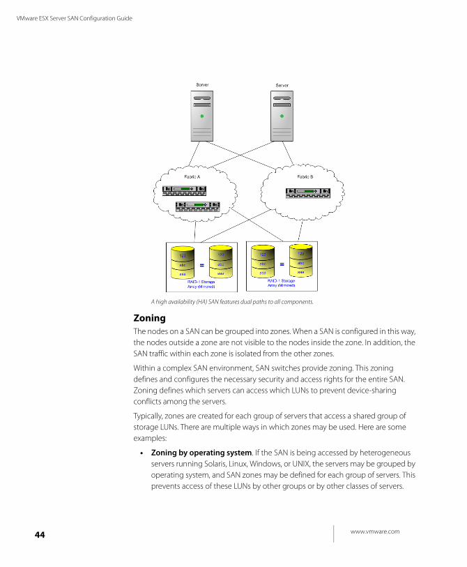
High Availability TopologyThe goal of a SAN designed for high availability is to function continuously, even if any of its individual components fail. High availability is achieved through the use of redundant components and paths from the host servers through the SAN switches to the storage arrays.
SANs that are designed for high availability may contain dual fabrics. Each server and storage array interfaces to two separate SAN switches that provide completely separate paths from the server to the storage array. Each server has at least one HBA connected to each SAN switch.
Operationally, the SAN may allow each fabric to share the I/O load or one fabric may be active and the other passive. In this second case, there is a switchover to the second fabric in the event that there is an I/O or a path failure in the first fabric.
High availability SANs offer fault resilience by being able to continue functioning after the failure of a component, path, device, or SAN switch. An added benefit of using a second SAN fabric is that maintenance of the SAN is easier: if necessary, the second fabric operates while the first fabric is being repaired.
www.vmware.com44
VMware ESX Server SAN Configuration Guide
A high availability (HA) SAN features dual paths to all components.
ZoningThe nodes on a SAN can be grouped into zones. When a SAN is configured in this way, the nodes outside a zone are not visible to the nodes inside the zone. In addition, the SAN traffic within each zone is isolated from the other zones.
Within a complex SAN environment, SAN switches provide zoning. This zoning defines and configures the necessary security and access rights for the entire SAN. Zoning defines which servers can access which LUNs to prevent device-sharing conflicts among the servers.
Typically, zones are created for each group of servers that access a shared group of storage LUNs. There are multiple ways in which zones may be used. Here are some examples:
• Zoning by operating system. If the SAN is being accessed by heterogeneous servers running Solaris, Linux, Windows, or UNIX, the servers may be grouped by operating system, and SAN zones may be defined for each group of servers. This prevents access of these LUNs by other groups or by other classes of servers.
C H A P T E R 3 Storage Area Network Concepts
45
• Backups. Another use of zones is to allow common server access for backups. SAN designs often have a backup server with tape services that require SAN-wide access to host servers individually for backup and recovery processes. These backup servers need to be able to access the servers they back up. A SAN zone may be defined for the backup server to access a particular host to perform a backup or recovery process when the backup server is ready to perform backup or recovery processes on that host.
• Security. Zoning also provides security. Zones defined for testing can be managed independently within the SAN and do not interfere with the activity going on in the production zones.
• Multiple Storage Arrays. Zones are also useful when there are multiple storage arrays. Through the use of separate zones, each storage array can be managed separately from the others, with no concern for access conflicts between servers.
Fault Tolerance TopologyThe ability for the entire SAN environment to sustain and recover from a failure is an essential design goal. This section discusses ways of making your SAN fault tolerant.
• Redundant SAN components. At the hardware level, redundant SAN components are required. This includes HBAs, SAN switches, and storage array access ports. In some cases, multiple storage arrays are part of a fault tolerant SAN design.
• Redundant I/O paths. From an operational viewpoint, I/O paths from the server to the storage array must also be redundant and dynamically switchable in the event that a failure occurs of a port, device, cable, or path.
• I/O Configuration. The key to providing fault tolerance is within the configuration of each server’s I/O system.
• With multiple HBAs, the I/O system can perform I/O operations across any of the HBAs to the assigned LUNs.
• In the event of a HBA, cable, or SAN switch port failure, the path is no longer available and an alternate path is required.
• If there is a failure in the primary path between the SAN switch and the storage array, then an alternate path at that level is required.
• In the event that a SAN switch fails, the entire path from server to storage array is disabled, so a second fabric with a complete alternate path is required.
www.vmware.com46
VMware ESX Server SAN Configuration Guide
• Mirroring. From a server application perspective, protection against LUN failure allows the application to sustain faults in its access of storage. This is often accomplished through the use of mirroring.
Mirroring designates a second non-addressable LUN that captures all writes to the primary LUN. With this technique, mirroring provides fault tolerance at the LUN level. LUN mirroring can be implemented at the server, SAN switch, or storage array level.
• Duplication of SAN environment. For extreme high availability requirements, SAN environments may be duplicated to provide disaster recovery on a site basis. This requires duplication of the SAN environment at different physical locations. The two resultant SAN environments may share operational workloads or the second SAN environment may be a failover-only site.
C H A P T E R 3 Storage Area Network Concepts
47
SAN Installation IssuesInstalling a SAN requires careful attention to details and an overall plan that addresses all the hardware, software, storage, and applications issues and interactions in the integration of all the pieces.
Overall, integrating all the component parts of the SAN requires meeting the supported hardware and software compatibility certifications by the various vendors.
The following list outlines the necessary certifications for each component:
• Applications (current version, patch list for this version)
• Database (patch list)
• Operating system (patch list)
• Volume manager (version, patch list)
• HBA (firmware version, driver version, patch list)
• HBA (fail-over driver patch list)
• Switch (firmware, OS driver/layer patch list)
• Storage (firmware, host personality firmware, patch list)
In addition, many of the SAN components require configuration settings to conform to the SAN design specifications.
During integration testing make sure you test all the operational processes for the SAN environment. These include normal production processing, failure mode testing, backup functions, and so forth.
Once testing is complete, establish a baseline of performance for each component as well as for the entire SAN. Each baseline provides a measurement metric for future changes and tuning.
Lastly, the SAN installation should be documented, and all operational procedures scripted and documented.
www.vmware.com48
VMware ESX Server SAN Configuration Guide
SAN Backup ConsiderationsWithin the SAN environment, backup processes have two goals. The first goal is to archive online data to offline media. This process is repeated periodically for all applications on a time schedule. The second goal is to provide access to offline data for recovery from a problem. For example, database recovery often requires retrieval of archived log files that are not currently online.
Configuration of a backup process depends on a number of factors:
• Identification of critical applications that require more frequent backup cycles within a given period of time.
• Resource availability for archiving data; usually, offline media access (tape)
• Impact on overall SAN environment
• Identification of peak traffic periods on the SAN (Backups scheduled during those peak periods may slow the applications and the backup process)
• Impact on storage performance while backing up
• Impact on other applications
• Time to schedule all backups within the data center
• Time it takes to back up an individual application
For a SAN, one goal is to design a recovery-time objective for each application. All too often, backups are scheduled to a time slot without regard to the time and resources necessary to re-provision the data. As each backup represents a recovery point, a secondary consideration is how long it takes to recover the data. If a scheduled backup stores so much data that recovery requires a considerable amount of time, the scheduled backup should be re-examined, and possibly be performed more frequently, so that less data is backed up and recovery of that data does not take too much time.
In other words, when you design recovery-time objectives you need to factor in the time it takes to recover from a data failure. If a particular application requires recovery within a certain time frame, then the backup process needs to provide a time schedule and specific data processing to meet this time factor. Fast recovery may require the use of recovery volumes that reside on online storage to minimize or eliminate the need to access slow, offline media for missing data components.
Optimal backup strategies may require using common backup solutions across the SAN. Earlier generations of applications focused on backup from within the
C H A P T E R 3 Storage Area Network Concepts
49
application. This created inefficiencies due to the heterogeneous nature of applications, databases, operating systems, and hardware platforms.
Common backup programs and the use of storage-based replication features provide a common approach to backups across all applications and platforms.
www.vmware.com50
VMware ESX Server SAN Configuration Guide
Booting from a SANSAN environments support booting off the SAN itself. For a system to boot from SAN:
1. The operating system is installed on one or more disks in the SAN (creating boot disks with the operating system image).
2. The host servers are informed where the boot disks are located.
3. When the host servers are started, they boot from the disks on the SAN.
Booting off a SAN provides numerous benefits, including:
• Easier maintenance of operating system patches, fixes, and upgrades for multiple servers — The operating system image needs to be maintained only on the boot disks in the SAN, yet can be made available to numerous application host servers.
• Greater reliability — If a server fails, it does not impact other host servers using the same operating system if those servers boot from the SAN.
• Easier disaster recovery — If the servers boot from the SAN, the boot disks can be replicated to a disaster recovery site.
• Easier backup processes: — The system boot disks in the SAN can be backed up as part of the overall SAN backup procedures.
• Improved management — Creation and management of operating system image is easier and more efficient. It is also easier to replace servers without major concern for its internal storage.
General requirements for booting off a SAN include:
• There must be support within the HBA, driver, software, operating system I/O, and switch protocol settings (zoning, fabric logins, etc) to allow SAN boots.
• When the HBA supports booting from the SAN, the server must have a special HBA driver for this function.
• The operating system must be able to configure booting off a SAN using pre-established HBA and SAN paths and settings.
• The storage array must accommodate operating systems requirements (for example, some operating systems require LUN 0 as the boot device).
• There must be multiple LUN 0 mappings for multiple server boots.
Note: If multiple servers boot from a SAN, the boot sequences from the servers must be staggered so that they do not all boot at the same time, which would cause a bottleneck and impact the overall SAN performance.
C H A P T E R 3 Storage Area Network Concepts
51
ClusteringServer clustering is a method of tying two or more servers together using a high-speed network connection so that the group of servers functions as a single, logical server. If one of the servers fails, then the other servers in the cluster continue operating, picking up the operations performed by the failed server.
Although clustering is not specifically a component of SANs, SANs are always employed to support server clustering. Specifically, in order for the group of servers in the cluster to function together, they need to share a common pool of storage and the SAN provides that capability.
Server clustering provides a highly available environment for applications that is highly scalable. Many vendors provide server clustering applications, including IBM, Sun, HP, Oracle, Microsoft, and Novell.
www.vmware.com52
VMware ESX Server SAN Configuration Guide
References for Information on SANsNumerous resources exist for information on storage area networks, from vendors and independent authors alike. The following resources are highly recommended:
• www.searchstorage.com
• www.snia.org
You should also familiarize yourself with the vendors (such as Emulex, QLogic, Brocade, Hewlett Packard, and many more), their product offerings, and the roles of these products in establishing a storage area network.
C H A P T E R 3 Storage Area Network Concepts
53
ESX Server Systems and Storage Area
NetworksVMware ESX Server can be used effectively with SANs, and generally can be used in any SAN configuration. There are some restrictions as to how certain SAN features are supported, as well as what specific equipment can be used as SAN components. The following subsections highlight some aspects of implementing a SAN solution with the ESX Server system. For more information, see Chapter 4, "ESX Server SAN Requirements" on page 57.
Host Bus AdaptersVMWare ESX Server supports Emulex and QLogic host bus adapters (and the HP OEM version of the QLogic adapters) for connection to switched-fabric SANs. When choosing an HBA for use with ESX Server systems, three critical factors need to be validated for full support:
• HBA model number
• HBA driver version
• HBA firmware version
You should always check the document referenced in Latest Information on SAN Support for ESX on page 55 to verify the necessary data for your HBAs.
To see how HBAs are set up with ESX Server systems, see Chapter 5, "Setting Up HBAs for SAN with ESX Server" on page 65 of this guide.
Storage ArraysVMware ESX Server supports a variety of storage arrays in various configurations. Not all storage devices can support all features and capabilities of ESX Server. Check http://www.vmware.com/pdf/esx_SAN_guide.pdf for the latest information regarding storage arrays planned for your SAN configuration
VMware tests ESX Server systems with storage arrays in the following configurations:
• Basic Connectivity —The ability for ESX Server to recognize and interoperate with the storage array. This configuration does not allow for multipathing or any type of failover.
• Multipathing — The ability for ESX Server to handle multiple paths to the same storage device.
www.vmware.com54
VMware ESX Server SAN Configuration Guide
• HBA Failover — In this configuration, the server is equipped with multiple HBAs connecting to one or more SAN switches — the server is robust to HBA and switch failure only.
• Storage Port Failover — In this configuration, the server is attached to multiple storage ports and is robust to storage port failures.
• Boot From SAN — In this configuration, the ESX Server boots from a LUN stored on the SAN rather than in the server itself.
To see how storage arrays are set up on SANs for ESX Server, see Chapter 6, "Setting Up SAN Storage Devices with ESX Server" on page 71 of this Guide.
Booting from the SANYou can configure your ESX Server machine to boot from a LUN on the SAN array, thereby eliminating the need for a local SCSI boot disk on the ESX Server.
When you have a SAN configured with your ESX Server machine, you have the option to configure one of the drives within the SAN to be the ESX Server boot disk. The storage devices must meet specific criteria in order to boot the ESX Server from the SAN, so that not all models of all storage arrays support this feature.
See ESX Server Boot from SAN Requirements on page 60 for more information, as well as the SAN support guide at http://www.vmware.com/pdf/esx_SAN_guide.pdf.
Chapter 7, "Preparing Your SAN for Booting Your ESX Server System" on page 87 provides information on configuring your SAN and ESX Server systems to utilize this feature.
Clustering with ESX ServerWith respect to ESX Server and SANs, clustering provides for load balancing of your clustered virtual machines, as well as failover support of your operating systems in virtual machines. Although clustering is generally defined between virtual machines, you can also define clustering between a virtual machine running on an ESX Server system and a physical Windows server.
Clustered virtual machines may reside on the same ESX Server system, or they may be distributed over multiple ESX Server systems. When you are using a SAN to support multiple ESX Server systems, the primary requirement is that all the clustered virtual machines be resident on VMFS (Virtual Machine File System) volumes within the SAN.
ESX Server 2.5 supports virtual machine clustering configurations with Microsoft Cluster Services (MSCS) on Windows 2000 and, for most SAN storage devices, Windows 2003. Cluster support is restricted to 2-node clusters for all configurations.
C H A P T E R 3 Storage Area Network Concepts
55
For more information on clustering of virtual machines on ESX Server, see:
• http://www.vmware.com/solutions/continuity/clustering.html
• http://www.vmware.com/support/esx25/doc/esx25admin_cluster_setup_esx.html
• ESX Server MSCS Clustering Requirements on page 63
• Latest Information on SAN Support for ESX on page 55
Latest Information on SAN Support for ESXVMware maintains a support guide that describes in detail the combinations of HBAs and storage devices currently tested by VMware and its storage partners.
This support guide is a live document that is updated frequently, with new certifications being added as they complete.
Before deploying ESX Server, please check the latest version of this document online at:
http://www.vmware.com/pdf/esx_SAN_guide.pdf
Important NoteVMware ESX Server has been tested and deployed in a variety of SAN environments. However, in practice, because every customer's device combination, topology, and configuration are unique, VMware recommends that you engage VMware professional services to install and configure the initial ESX Server installation in your SAN environment.

www.vmware.com56
VMware ESX Server SAN Configuration Guide
C H A P T E R 4
57
ESX Server SAN Requirements
This chapter presents important hardware and system requirements for enabling an ESX Server system to function with a storage area network (SAN). The chapter consists of the following sections:
• General ESX Server SAN Requirements on page 58
• ESX Server Boot from SAN Requirements on page 60
• ESX Server MSCS Clustering Requirements on page 63
www.vmware.com58
VMware ESX Server SAN Configuration Guide
General ESX Server SAN RequirementsLarge storage systems (also known as disk arrays) combine numerous disks into arrays for availability and performance. Typically, a collection of disks is grouped into a Redundant Array of Independent Disks (RAID) to protect the data by eliminating disk drives as a potential single point of failure.
Disk arrays carve the storage RAID set into logical units (LUNs) that are presented to the server in a manner similar to an independent single disk. Typically, LUNs are few in number, relatively large, and fixed in size. When you use SAN in conjunction with an ESX Server:
• You can create LUNs with the storage management application of your disk array.
• You can share LUNs between ESX Server machines to provide shared VMFS file systems.
• You can configure your ESX Server machine to boot from a LUN on the SAN array, thereby eliminating the need for a local SCSI disk.
ESX Server supports QLogic and Emulex host bus adapters, which allow an ESX Server machine to be connected to a SAN and use the LUNs on the SAN.
In preparation for configuring your SAN, and for setting up ESX Server to run with the SAN, be sure the following requirements are met:
• Supported SAN hardware: Download an up-to-date VMware ESX Server SAN Compatibility List from the VMware Web site at //www.vmware.com/pdf/esx_SAN_guide.pdf.
• VMFS volumes (accessibility modes): Any VMFS volume on a disk that is on a SAN can have VMFS accessibility set to public or shared:
• Public accessibility is the default accessibility mode and is generally recommended. It makes the VMFS volume available to multiple physical servers. For VMFS-2 volumes, public access is concurrent to multiple physical servers. For VMFS-1 volumes, public access is limited to a single server at a time.
• Shared accessibility is the required mode for VMFS volumes if you are using physical clusters without raw device mapping.
• VMFS volumes: Ensure that only one ESX Server system has access to the SAN while you are using the VMware Management Interface to format VMFS-2 volumes. After you have configured the VMFS volumes, make sure that all
C H A P T E R 4 ESX Server SAN Requirements
59
partitions on the shared disk are set for public or shared access so multiple ESX Servers have access.
• It is not recommended that you set up the dump partition on a SAN LUN. However, a dump partition is supported, as in the case of boot from SAN.
• Define persistent bindings (unless you are using raw disk mapping).
• Raw device mapping is recommended for any access to any raw disk from an ESX Server 2.5 or later machine.
If a raw disk is directly mapped to a physical disk drive on your SAN, the virtual machines in your ESX Server system directly access the data on this disk as a raw device (and not as a file on a VMFS volume).
www.vmware.com60
VMware ESX Server SAN Configuration Guide
ESX Server Boot from SAN RequirementsWhen you have a SAN configured with your ESX Server machine, you have the option to configure one of the drives within the SAN to be the ESX Server boot disk. This disk must meet certain criteria in order to boot the ESX Server system from the SAN.
In addition to the general configuration processes for SAN with ESX Server, the following tasks must be completed to enable ESX Server to boot from SAN:
• Ensure the configuration settings meet the basic boot from SAN requirements (lowest LUN, lowest target, primary path irrespective of active or passive configurations, and the boot path /dev/sda).
• Prepare the hardware elements, including the host bus adapter, network devices, and storage system.
Refer to the product documentation for each device.
• Configure your SAN devices.
Hardware Requirements for Booting from SANSee the SAN Compatibility Guide (//www.vmware.com/pdf/esx_SAN_guide.pdf ) for the most current list of:
• Host bus adapters
• Arrays with support for booting from SAN
• SAN firmware
SAN Configuration Requirements for Booting from SAN• ESX Server 2.5 or later.
• ESX Server installed with the bootfromsan or bootfromsan-text option. Refer to the VMware ESX Server Installation Guide at //www.vmware.com/support/pubs/.
• The HBA used for the boot LUN cannot be dedicated to the VMkernel; that is, the HBA must be configured as a shared device.
• If the storage array uses active-passive path configuration, the lowest-numbered path to the boot LUN must be the active path.
When you boot from an active-passive storage array, the storage processor whose world wide name (WWN) is specified in the BIOS configuration of the HBA must be active. If the storage processor is passive, the QLogic adapter cannot support the boot process.
C H A P T E R 4 ESX Server SAN Requirements
61
• Each boot LUN must be masked so that it can only be seen by its own ESX Server system. Each ESX Server machine must see its own boot LUN, but not the boot LUN of any other ESX Server machine.
• SAN connections must be through a switch fabric topology; boot from SAN does not support Direct Connect or Fibre Channel arbitrated loop connections.
• Raw device mapping (RDM) is not supported in conjunction with the boot from SAN feature. Also, MSCS failover using RDM is not supported in conjunction with the boot from SAN feature. However, cluster failover of ESX Server virtual machines using shared VMFS volumes is still supported.
• The HBA controlling the boot LUN must be a QLogic HBA; currently only the 23xx series is supported.
ESX Server Configuration Requirements for Booting from SAN• The HBA BIOS for your QLogic HBA Fibre Channel card must be enabled and
correctly configured to access the boot LUN.
• The booting logical unit number (LUN) must be visible from the lowest numbered HBA that has any visible LUNs.
• The boot LUN must be visible from the lowest numbered storage processor (attached to that HBA) that has any visible LUNs.
• The boot LUN must be the lowest numbered LUN attached to that storage processor (except for gatekeeper LUNs which are sometimes assigned LUN0).
• You must remove all internal SCSI drives. for all servers.
• HBA numbers can change automatically when you add and remove PCI adapters, or manually when you edit the /etc/vmware/devnames.conf file. The HBA must be set to the lowest PCI bus and slot number. This enables it to be detected very quickly since the drivers scan the HBAs in ascending PCI bus and slot numbers, regardless of the associated virtual machine HBA number.
• If you are running an IBM eServer BladeCenter and boot from SAN, you must disable IDE drives on the blades.
ESX Server SAN requirements for Booting from SAN• Sample devices, numbers, and choice
• Boot LUN redundancy
• Clustering/failover configuration
• Storage arrays
www.vmware.com62
VMware ESX Server SAN Configuration Guide
• LUNs, switches, or HBA to a boot from SAN configuration
• SCSI status data for virtual machines
• Multipathing (redundant and non-redundant) configurations
Redundant and non-redundant configurations are supported. In the redundant case, ESX Server collapses the redundant paths so only a single path to a LUN is presented to the user.
ESX Server with SAN features that are not supported in boot from SAN mode include:
• MSCS failover using RDM. Shared VMFS volumes are still supported
• Raw device mapping

C H A P T E R 4 ESX Server SAN Requirements
63
ESX Server MSCS Clustering
RequirementsClustering provides for failover support of your operating systems in virtual machines. When you use a SAN to support multiple ESX Server machines, the primary requirement is that all the clustered virtual machines must reside on local storage. Shared disk and quorum must be located on the SAN.
• If you are using Microsoft Clustering Services, you cannot boot your ESX Server machines from the SAN or use the raw device mapping feature.
• If you are using other clustering services that rely on access to the VMFS volume, the ESX Server boot from SAN option is still viable.
See to the Microsoft Clustering Services documentation and the VMware ESX Server Administration Guide (at //www.vmware.com/support/pubs/) for information on clustering ESX Server virtual machines.
Using ESX Server with MSCS clustering has the following requirements:
• ESX Server version 2.5
• Microsoft Clustering Service
• SAN devices and storage systems

www.vmware.com64
VMware ESX Server SAN Configuration Guide
C H A P T E R 5
65
Setting Up HBAs for SAN with ESX Server
This chapter discusses Host Bus Adapter (HBA) configuration. ESX Server supports QLogic and Emulex HBA devices.
The sections in this chapter are:
• Configuring Your QLogic HBA BIOS on page 66
• Configuring the Emulex HBA BIOS on page 69
Notes• Boot from SAN is supported with QLogic HBAs, but not with Emulex HBAs. See
Chapter 7, "Preparing Your SAN for Booting Your ESX Server System" on page 87 for information on booting the ESX Server from the SAN.
• SAN storage devices supported by ESX Server are described in Setting Up SAN Storage Devices with ESX Server on page 71.
• For the latest support information, see the ESX Server SAN Compatibility Guide at www.vmware.com/support/resources/esx_resources.html .

www.vmware.com66
VMware ESX Server SAN Configuration Guide
Configuring Your QLogic HBA BIOSClustering virtual machines between your ESX Server machines requires shared disks. If you intend to access shared disks on a SAN using a QLogic HBA, you must use particular values for some QLogic HBA configuration settings.
To verify the QLogic HBA settings:
1. Reboot your physical machine.
2. Enter the QLogic HBA configuration utility during bootup. Under Advanced Configuration Settings, ensure that:
• Enable Target Reset is set to Yes.
• Full LIP Login is set to Yes.
• Full LIP Reset is set to No.
Configuring the QLogic HBA BIOS to boot ESX Server from SAN includes a number of tasks discussed immediately below. They include:
• Enabling the HBA BIOS
• Enabling selectable boot
• Selecting the boot LUN
To configure your QLogic HBA BIOS:
1. If you are using an IBM BladeCenter, disconnect all your local disk drives from the server.
2. Enter the BIOS Fast!UTIL configuration utility.
a. Boot the server.
b. While booting the server, press Ctrl-Q.
3. If you have only one host bus adapter (HBA), the Fast!UTIL Options screen appears. Skip to step 5.
4. If you have more than one HBA, select the HBA manually as follows:
a. In the Select Host Adapter screen, use the arrow keys to position the cursor on the appropriate HBA.
b. Press Enter.
Note: If you are planning to use this HBA for booting your ESX Server from the SAN, select the lowest numbered HBA that has any LUNs visible.
5. In the Fast!UTIL Options screen, select Configuration Settings and press Enter.
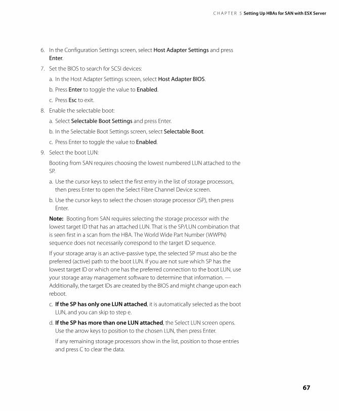
C H A P T E R 5 Setting Up HBAs for SAN with ESX Server
67
6. In the Configuration Settings screen, select Host Adapter Settings and press Enter.
7. Set the BIOS to search for SCSI devices:
a. In the Host Adapter Settings screen, select Host Adapter BIOS.
b. Press Enter to toggle the value to Enabled.
c. Press Esc to exit.
8. Enable the selectable boot:
a. Select Selectable Boot Settings and press Enter.
b. In the Selectable Boot Settings screen, select Selectable Boot.
c. Press Enter to toggle the value to Enabled.
9. Select the boot LUN:
Booting from SAN requires choosing the lowest numbered LUN attached to the SP.
a. Use the cursor keys to select the first entry in the list of storage processors, then press Enter to open the Select Fibre Channel Device screen.
b. Use the cursor keys to select the chosen storage processor (SP), then press Enter.
Note: Booting from SAN requires selecting the storage processor with the lowest target ID that has an attached LUN. That is the SP/LUN combination that is seen first in a scan from the HBA. The World Wide Part Number (WWPN) sequence does not necessarily correspond to the target ID sequence.
If your storage array is an active-passive type, the selected SP must also be the preferred (active) path to the boot LUN. If you are not sure which SP has the lowest target ID or which one has the preferred connection to the boot LUN, use your storage array management software to determine that information. — Additionally, the target IDs are created by the BIOS and might change upon each reboot.
c. If the SP has only one LUN attached, it is automatically selected as the boot LUN, and you can skip to step e.
d. If the SP has more than one LUN attached, the Select LUN screen opens. Use the arrow keys to position to the chosen LUN, then press Enter.
If any remaining storage processors show in the list, position to those entries and press C to clear the data.
www.vmware.com68
VMware ESX Server SAN Configuration Guide
e. Press Esc twice to exit, then press Enter to save the setting.
10. In your system BIOS setup, change the system boot sequence to boot from CD-ROM first . For example, on the IBM X-Series 345 server, do the following:
a. During your system power up, enter the system BIOS Configuration/Setup Utility.
b. Select Startup Options and press Enter.
c. Select Startup Sequence Options and press Enter.
d. Make the First Startup Device: [CD-ROM]
11. Proceed with the ESX Server installation steps. Select boot: bootfromsan or bootfromsan-text option.
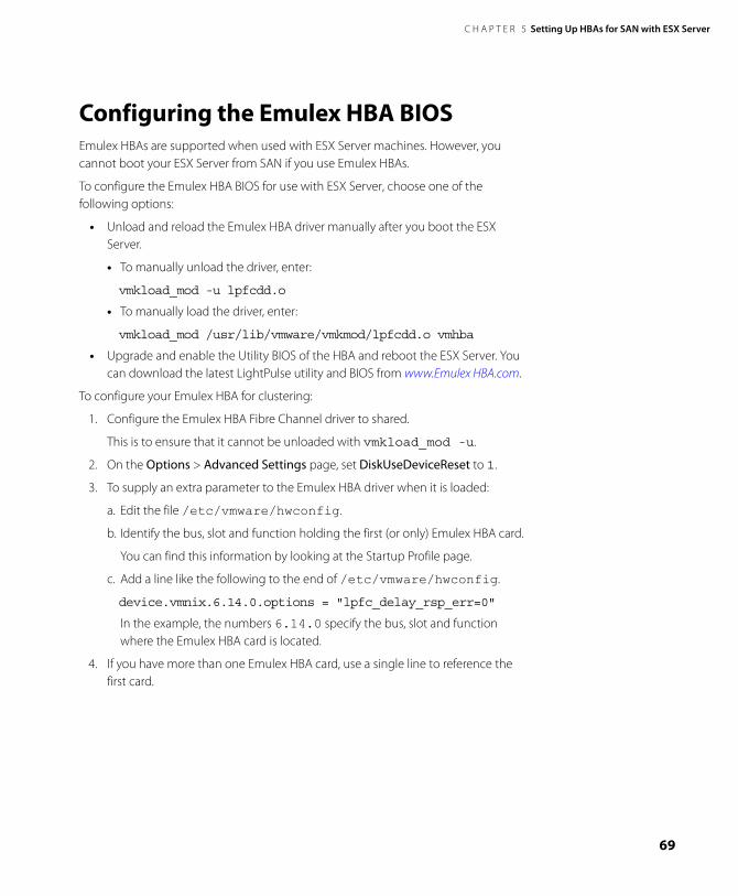
C H A P T E R 5 Setting Up HBAs for SAN with ESX Server
69
Configuring the Emulex HBA BIOS Emulex HBAs are supported when used with ESX Server machines. However, you cannot boot your ESX Server from SAN if you use Emulex HBAs.
To configure the Emulex HBA BIOS for use with ESX Server, choose one of the following options:
• Unload and reload the Emulex HBA driver manually after you boot the ESX Server.
• To manually unload the driver, enter:
vmkload_mod -u lpfcdd.o
• To manually load the driver, enter:
vmkload_mod /usr/lib/vmware/vmkmod/lpfcdd.o vmhba
• Upgrade and enable the Utility BIOS of the HBA and reboot the ESX Server. You can download the latest LightPulse utility and BIOS from www.Emulex HBA.com.
To configure your Emulex HBA for clustering:
1. Configure the Emulex HBA Fibre Channel driver to shared.
This is to ensure that it cannot be unloaded with vmkload_mod -u.
2. On the Options > Advanced Settings page, set DiskUseDeviceReset to 1.
3. To supply an extra parameter to the Emulex HBA driver when it is loaded:
a. Edit the file /etc/vmware/hwconfig.
b. Identify the bus, slot and function holding the first (or only) Emulex HBA card.
You can find this information by looking at the Startup Profile page.
c. Add a line like the following to the end of /etc/vmware/hwconfig.
device.vmnix.6.14.0.options = "lpfc_delay_rsp_err=0"
In the example, the numbers 6.14.0 specify the bus, slot and function where the Emulex HBA card is located.
4. If you have more than one Emulex HBA card, use a single line to reference the first card.

www.vmware.com70
VMware ESX Server SAN Configuration Guide
C H A P T E R 6
71
Setting Up SAN Storage Devices with ESX Server
This chapter describes the configuration required to use SAN storage devices with your ESX Server.
The supported storage devices are:
• IBM TotalStorage series (formerly FAStT) disk storage systems
• EMC Symmetrix networked storage systems
• EMC Clariion storage systems
• HP StorageWorks Smart Array storage array systems
Host Bus Adaptors (HBAs) that are supported for use with your ESX Server are described in Setting Up HBAs for SAN with ESX Server on page 65.
Refer to your ESX Server SAN Compatibility Guide at www.vmware.com/support/resources/esx_resources.html for the latest support information.
www.vmware.com72
VMware ESX Server SAN Configuration Guide
The sections in this chapter are:
• Configuring IBM TotalStorage (FAStT) Storage Systems for Clustering on page 73
• Configuring EMC Symmetrix Storage Systems on page 80
• Configuring EMC CLARiiON Storage Systems on page 82
• Configuring Dell/EMC Fibre Channel Storage Systems on page 83
• Configuring HP StorageWorks Storage Systems on page 84
C H A P T E R 6 Setting Up SAN Storage Devices with ESX Server
73
Configuring IBM TotalStorage (FAStT)
Storage Systems for ClusteringTo configure an IBM FAStT storage array to use clustering as well as multipathing with HBA and storage port failover on an ESX Server 2.1 or later machine, ensure the following requirements are met:
• Each ESX Server machine must have multiple paths to the LUN, using redundant HBAs, switches, and storage processors.
• The storage processors should have auto-volume transfer (AVT) disabled.
• The host type for the storage processors should be set to the Linux specifying parameter, LNXCL.
• The multipathing policy for the LUN should be set to Most Recently Used. (MRU). This is done by default. No action is required unless you have changed it to FIXED, in which case you need to return it to an MRU multipath policy.
• The HBAs should have persistent bindings specified.
• The VMkernel on each ESX Server machine should use LUN reset in place of bus reset.
Refer to the IBM Redbook, Implementing VMWare ESX Server with IBM TotalStorage FAStT at www.redbooks.ibm.com/redbooks/pdfs/sg246434.pdf.
In addition to normal configuration steps for your IBM TotalStorage storage system, perform the tasks described in the following sections:
• Configuring the Hardware for SAN Failover with FAStT Storage Servers
• Verifying the Storage Processor Port Configuration
• Disabling AVT
• Configuring Storage Processor Sense Data
• Verifying Multipath Information
• Resetting Persistent Bindings
• Configuring LUN Reset
• Configuring for a LUN 0 Gatekeeper LUN with Symmetrix
www.vmware.com74
VMware ESX Server SAN Configuration Guide
Configuring the Hardware for SAN Failover with FAStT Storage Servers To set up a highly available SAN failover configuration with FAStT storage models equipped with two storage processors, you need the following hardware components:
• Two Fibre Channel host bus adapters (HBAs), such as QLogic or Emulex, on each ESX Server machine. See Setting Up HBAs for SAN with ESX Server on page 65.
• Two fibre switches connecting the HBAs to the SAN. For example: SW1 and SW2.
• Two storage processors (SPs). For example: SPA and SPB.
Each storage processor must have at least two ports connected to the SAN.
Use the following connection settings for the ESX Server:
• Connect each HBA on each ESX Server machine to a separate switch. For example, connect HBA0 and HBA1 to SW1 and SW2, respectively.
• Connect SPA to a lower switch port number than SPB on SW1, to ensure that SPA is listed first. For example, connect SW1 to port 1 on SPA and port 2 on SPB.
• Connect SPA to a lower switch port number than SPB on SW2, to ensure that SPA is listed first. For example, connect SW2 to port 2 on SPA and to port 1 on SPB.
This configuration provides two paths from each HBA, so each element of the connection is able to fail over to a redundant path. The order of the paths in the above configuration provides HBA and switch failover without the need to trigger Auto-Volume Transfer (AVT). LUNs must be owned by the storage processor to which the preferred and active paths are connected (in the example configuration above, they should be owned by SPA). Only a storage processor failure triggers AVT on the FAStT Storage Server.
Note: The above examples assume that the switches are not connected through an Inter-Switch Link (ISL) in one fabric.
Verifying the Storage Processor Port ConfigurationTo view storage processors and related ports on the preferred path, log on to the ESX Server machine as root and enter the following command:
wwpn.pl -v
The output lists the World Wide Port Names (WWPNs) of HBAs on the ESX Server machine and storage processors on the FAStT.
Compare these to those listed in the FAStT profile.
C H A P T E R 6 Setting Up SAN Storage Devices with ESX Server
75
The target numbers and WWPNs must be identical as seen by each ESX Server machine connected to the same FAStT.
Disabling AVT To avoid the possibility of path thrashing, disable AVT (Auto Volume Transfer) on the SAN storage processors. If AVT is enabled, the two storage processors can alternately take ownership of the LUN from each other in certain situations, resulting in performance degradation. AVT is also known as ADT (Auto Disk Transfer).
ESX Server supports active/passive configurations. If you are using active/passive SAN configuration, disable the AVT to prevent path thrashing.
To disable AVT, set the host type to LNXCL in the FAStT Storage Manager for each host group containing HBAs for one or more ESX Server machines.
Note: You need to reboot the ESX Server machine after changing the AVT configuration.
Configuring Storage Processor Sense DataStorage processors can be configured to return either Unit Attention or Not Ready when quiescent. A FAStT storage processor that is running Windows as a guest operating system should return Not Ready sense data when quiescent. Returning Unit Attention might cause the Windows guest to crash during a failover.
To configure the storage processors to return Not Ready sense data, follow these steps:
1. Determine the index for the host type LNXCL by using the following commands in a shell window:
SMcli.exe <ip-addr-for-sp-A>
show hosttopology;
<EOF>
SMcli.exe <ip-addr-for-sp-B>
show hosttopology;
<EOF>
The following commands assume 13 is the index corresponding to LNXCL in the NVSRAM host type definitions. If your storage processors have LNXCL at a different index, substitute that index for 13 in the following commands.
2. Execute these commands for storage processor A to have it return Not Ready sense data:
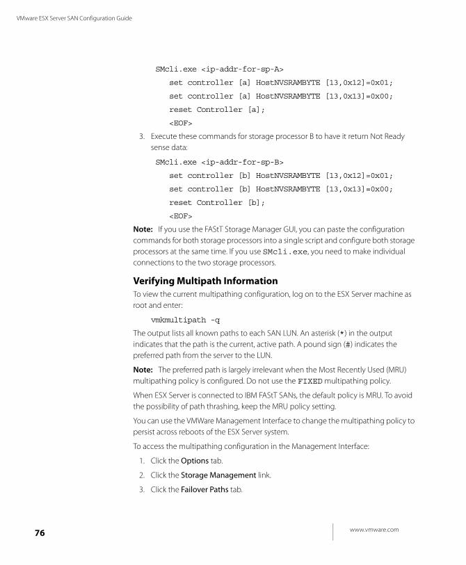
www.vmware.com76
VMware ESX Server SAN Configuration Guide
SMcli.exe <ip-addr-for-sp-A>
set controller [a] HostNVSRAMBYTE [13,0x12]=0x01;
set controller [a] HostNVSRAMBYTE [13,0x13]=0x00;
reset Controller [a];
<EOF>
3. Execute these commands for storage processor B to have it return Not Ready sense data:
SMcli.exe <ip-addr-for-sp-B>
set controller [b] HostNVSRAMBYTE [13,0x12]=0x01;
set controller [b] HostNVSRAMBYTE [13,0x13]=0x00;
reset Controller [b];
<EOF>
Note: If you use the FAStT Storage Manager GUI, you can paste the configuration commands for both storage processors into a single script and configure both storage processors at the same time. If you use SMcli.exe, you need to make individual connections to the two storage processors.
Verifying Multipath InformationTo view the current multipathing configuration, log on to the ESX Server machine as root and enter:
vmkmultipath -q
The output lists all known paths to each SAN LUN. An asterisk (*) in the output indicates that the path is the current, active path. A pound sign (#) indicates the preferred path from the server to the LUN.
Note: The preferred path is largely irrelevant when the Most Recently Used (MRU) multipathing policy is configured. Do not use the FIXED multipathing policy.
When ESX Server is connected to IBM FAStT SANs, the default policy is MRU. To avoid the possibility of path thrashing, keep the MRU policy setting.
You can use the VMWare Management Interface to change the multipathing policy to persist across reboots of the ESX Server system.
To access the multipathing configuration in the Management Interface:
1. Click the Options tab.
2. Click the Storage Management link.
3. Click the Failover Paths tab.
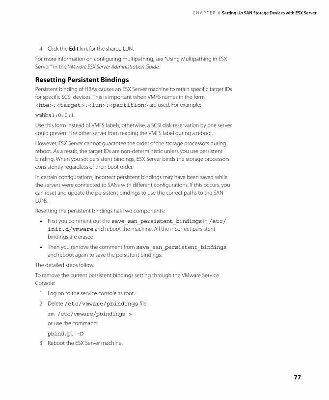
C H A P T E R 6 Setting Up SAN Storage Devices with ESX Server
77
4. Click the Edit link for the shared LUN.
For more information on configuring multipathing, see “Using Multipathing in ESX Server” in the VMware ESX Server Administration Guide.
Resetting Persistent Bindings Persistent binding of HBAs causes an ESX Server machine to retain specific target IDs for specific SCSI devices. This is important when VMFS names in the form <hba>:<target>:<lun>:<partition> are used. For example:
vmhba1:0:0:1
Use this form instead of VMFS labels; otherwise, a SCSI disk reservation by one server could prevent the other server from reading the VMFS label during a reboot.
However, ESX Server cannot guarantee the order of the storage processors during reboot. As a result, the target IDs are non-deterministic unless you use persistent binding. When you set persistent bindings, ESX Server binds the storage processors consistently regardless of their boot order.
In certain configurations, incorrect persistent bindings may have been saved while the servers were connected to SANs with different configurations. If this occurs, you can reset and update the persistent bindings to use the correct paths to the SAN LUNs.
Resetting the persistent bindings has two components:
• First you comment out the save_san_persistent_bindings in /etc/init.d/vmware and reboot the machine. All the incorrect persistent bindings are erased.
• Then you remove the comment from save_san_persistent_bindings and reboot again to save the persistent bindings.
The detailed steps follow.
To remove the current persistent bindings setting through the VMware Service Console:
1. Log on to the service console as root.
2. Delete /etc/vmware/pbindings file:
rm /etc/vmware/pbindings >
or use the command:
pbind.pl -D
3. Reboot the ESX Server machine.
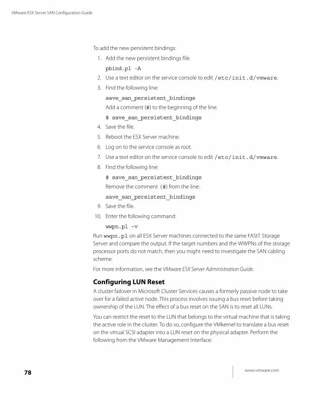
www.vmware.com78
VMware ESX Server SAN Configuration Guide
To add the new persistent bindings:
1. Add the new persistent bindings file.
pbind.pl -A
2. Use a text editor on the service console to edit /etc/init.d/vmware.
3. Find the following line:
save_san_persistent_bindings
Add a comment (#) to the beginning of the line:
# save_san_persistent_bindings
4. Save the file.
5. Reboot the ESX Server machine.
6. Log on to the service console as root.
7. Use a text editor on the service console to edit /etc/init.d/vmware.
8. Find the following line:
# save_san_persistent_bindings
Remove the comment (#) from the line:
save_san_persistent_bindings
9. Save the file.
10. Enter the following command:
wwpn.pl -v
Run wwpn.pl on all ESX Server machines connected to the same FAStT Storage Server and compare the output. If the target numbers and the WWPNs of the storage processor ports do not match, then you might need to investigate the SAN cabling scheme.
For more information, see the VMware ESX Server Administration Guide.
Configuring LUN Reset A cluster failover in Microsoft Cluster Services causes a formerly passive node to take over for a failed active node. This process involves issuing a bus reset before taking ownership of the LUN. The effect of a bus reset on the SAN is to reset all LUNs.
You can restrict the reset to the LUN that belongs to the virtual machine that is taking the active role in the cluster. To do so, configure the VMkernel to translate a bus reset on the virtual SCSI adapter into a LUN reset on the physical adapter. Perform the following from the VMware Management Interface:
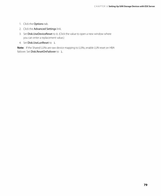
C H A P T E R 6 Setting Up SAN Storage Devices with ESX Server
79
1. Click the Options tab.
2. Click the Advanced Settings link.
3. Set Disk.UseDeviceReset to 0. (Click the value to open a new window where you can enter a replacement value.)
4. Set Disk.UseLunReset to 1.
Note: If the Shared LUNs are raw device mapping to LUNs, enable LUN reset on HBA failover. Set Disk.ResetOnFailover to 1.
www.vmware.com80
VMware ESX Server SAN Configuration Guide
Configuring EMC Symmetrix Storage
SystemsThe following settings are required on the Symmetrix networked storage system for ESX Server operations:
• Common serial number (C)
• Enable auto negotiation (EAN)
• Enable Fibrepath on this port (VCM)
• SCSI 3 (SC3)
• Unique world wide name (UWN)
See the EMC Symmetrix documentation for information on configuring your storage system.
Note: The EXS Server detects any LUNs less than 25 MB in capacity as management LUNs when connected to a fabric with the Symmetrix storage array. These are also known as pseudo or gatekeeper LUNs. These LUNs appear in the management interface and should not be used to hold data.
Configuring for a LUN 0 Gatekeeper LUN with SymmetrixSymmetrix uses LUN 0 as a gatekeeper LUN, which is marked as a pseudo-device. The ESX Server installer maps LUN 0 to /dev/sda. When the installer tries to configure the boot LUN, it is unable to use /dev/sda, so it uses /dev/sdb instead. A problem identifying the boot loader results.
There are two possible solutions to this problem.
• Changing the Gatekeeper LUN Number
• Changing the Boot Loader Configuration
Changing the Gatekeeper LUN Number To boot from SAN, ESX Server requires that the boot LUN be the lowest-numbered LUN in the storage array. If the gatekeeper LUN is LUN 0, it must be changed to a number higher than the boot LUN number. Current Fibre Channel adapters can boot only from LUN numbers up to 15, so your boot LUN number must be in the range 0 to 15. Renumber the gatekeeper LUN to 16 or higher, and it won't interfere with the boot LUN.
To renumber the LUN, either contact the vendor for assistance or consult your storage array management documentation.
C H A P T E R 6 Setting Up SAN Storage Devices with ESX Server
81
Changing the Boot Loader Configuration Another way to deal with the gatekeeper LUN is to specify in your boot configuration where to find the boot LUN. You can do so by editing the file /etc/lilo.conf.
Note: If you have already completed the installation and you are unable to boot the server, you should boot from a Linux rescue CD or mount the boot LUN from another server so you can make the following changes.
1. Back up the file /etc/lilo.conf.
2. Edit the file /etc/lilo.conf.
3. Find the line that says default=esx.
4. After the default line, insert these two lines:
disk=/dev/sdb
bios=0x80
Use a Tab at the beginning of the second line.
5. Exit the editor, saving changes.
6. Run lilo.
7. Reboot the server. This time, it should boot successfully from /dev/sdb.
www.vmware.com82
VMware ESX Server SAN Configuration Guide
Configuring EMC CLARiiON Storage
SystemsYour EMC CLARiiON storage systems work with ESX Server machines in SAN configurations. Basic configuration steps include:
1. Install and configure your storage device
2. Configure zoning at the switch level.
3. Create RAID groups.
4. Create and bind LUNs.
5. Register the servers connected to the SAN.
6. Create storage groups to contain the servers and LUNs.
Refer to your EMC documentation for information of configuring the storage systems.
C H A P T E R 6 Setting Up SAN Storage Devices with ESX Server
83
Configuring Dell/EMC Fibre Channel
Storage SystemsDell/EMC Fibre Channel storage systems work with ESX Server machines in SAN configurations. Basic configuration steps include:
1. Install and configure the storage device
2. Configure zoning at the switch level.
3. Create RAID groups.
4. Create and bind LUNs.
5. Register the servers connected to the SAN.
6. Create storage groups to contain the servers and LUNs.
Refer to your EMC and Dell documentation for information on configuring the storage systems.

www.vmware.com84
VMware ESX Server SAN Configuration Guide
Configuring HP StorageWorks Storage
SystemsTo use the HP StorageWorks MSA 1000 with ESX Server, you must configure the Fibre Channel connections between the SAN array and the ESX Server with the Profile Name set to Linux.
To set the Profile Name for a connection, follow these steps:
1. Create a static connection on the MSA 1000 using the MSA 1000 command line interface.
See the HP StorageWorks MSA 1000 documentation for information on installing and configuring the command line interface.
h18006.www1.hp.com/products/storageworks/msa1000/documentation.html
Note: You cannot create connection settings using the HP Array Configuration Utility.
2. Connect the MSA 1000 command-line interface to the MSA 1000.
3. Verify that the Fibre Channel network between the MSA 1000 and the ESX Server is working.
4. Start the command line interface. At the prompt, enter:
SHOW CONNECTIONS
The output displays a connection specification for each FC WWNN/WWPN attached to the MSA 1000:
Connection Name: <unknown>
Host WWNN = 20:02:00:a0:b8:0c:d5:56
Host WWPN = 20:03:00:a0:b8:0c:d5:57
Profile Name = Default
Unit Offset 0
Controller 1 Port 1 Status = Online
Controller 2 Port 1 Status = Online
5. Make sure the hosts WWNN and WWPN show the correct connection for each Fiber Channel adapter on the ESX Server machine.
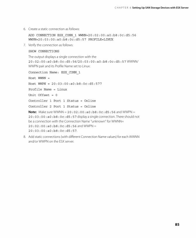
C H A P T E R 6 Setting Up SAN Storage Devices with ESX Server
85
6. Create a static connection as follows:
ADD CONNECTION ESX_CONN_1 WWNN=20:02:00:a0:b8:0c:d5:56 WWPN=20:03:00:a0:b8:0c:d5:57 PROFILE=LINUX
7. Verify the connection as follows:
SHOW CONNECTIONS
The output displays a single connection with the 20:02:00:a0:b8:0c:d5:56/20:03:00:a0:b8:0c:d5:57 WWNN/WWPN pair and its Profile Name set to Linux:
Connection Name: ESX_CONN_1
Host WWNN =
Host WWPN = 20:03:00:a0:b8:0c:d5:577
Profile Name = Linux
Unit Offset = 0
Controller 1 Port 1 Status = Online
Controller 2 Port 1 Status = Online
Note: Make sure WWNN = 20:02:00:a0:b8:0c:d5:56 and WWPN = 20:03:00:a0:b8:0c:d5:57 display a single connection. There should not be a connection with the Connection Name "unknown" for WWNN= 20:02:00:a0:b8:0c:d5:56 and WWPN = 20:03:00:a0:b8:0c:d5:57.
8. Add static connections (with different Connection Name values) for each WWNN and/or WWPN on the ESX server.

www.vmware.com86
VMware ESX Server SAN Configuration Guide
C H A P T E R 7
87
Preparing Your SAN for Booting Your ESX Server System
This chapter describes the tasks you need to perform before installing the ESX Server if you plan to have your ESX Server boot from a SAN disk.
Note: If you are not planning to have your ESX Server boot from a SAN, skip this chapter.
The chapter discusses the following topics:
• Preparing to Install for Boot From SAN on page 88
• Planning LUN Visibility for QLogic or Emulex HBAs on page 93
• Configuring VMFS Volumes on SANs on page 96
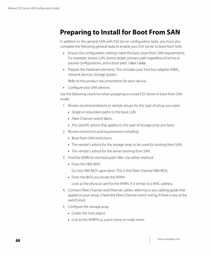
www.vmware.com88
VMware ESX Server SAN Configuration Guide
Preparing to Install for Boot From SANIn addition to the general SAN with ESX Server configuration tasks, you must also complete the following general tasks to enable your ESX Server to boot from SAN.
• Ensure the configuration settings meet the basic boot from SAN requirements. For example, lowest LUN, lowest target, primary path regardless of active or passive configurations, and a boot path /dev/sda.
• Prepare the hardware elements. This includes your host bus adapter (HBA), network devices, storage system.
Refer to the product documentation for each device.
• Configure your SAN devices.
Use the following check list when preparing to install ESX Server in boot from SAN mode:
1. Review recommendations or sample setups for the type of setup you want:
• Single or redundant paths to the boot LUN.
• Fibre Channel switch fabric.
• Any specific advice that applies to the type of storage array you have.
2. Review restrictions and requirements including:
• Boot-from-SAN restrictions.
• The vendor's advice for the storage array to be used for booting from SAN.
• The vendor's advice for the server booting from SAN.
3. Find the WWN for the boot path HBA. Use either method:
• From the HBA BIOS
Go into HBA BIOS upon boot. This is the Fibre Channel HBA BIOS.
• From the BIOS you locate the WWN
Look at the physical card for the WWN. It is similar to a MAC address.
4. Connect Fibre Channel and Ethernet cables, referring to any cabling guide that applies to your setup. Check the Fibre Channel switch wiring, if there is any at the switch level.
5. Configure the storage array.
• Create the host object.
• Link to the WWPN as a port name or node name.
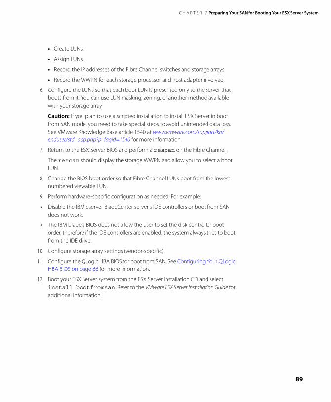
C H A P T E R 7 Preparing Your SAN for Booting Your ESX Server System
89
• Create LUNs.
• Assign LUNs.
• Record the IP addresses of the Fibre Channel switches and storage arrays.
• Record the WWPN for each storage processor and host adapter involved.
6. Configure the LUNs so that each boot LUN is presented only to the server that boots from it. You can use LUN masking, zoning, or another method available with your storage array
Caution: If you plan to use a scripted installation to install ESX Server in boot from SAN mode, you need to take special steps to avoid unintended data loss. See VMware Knowledge Base article 1540 at www.vmware.com/support/kb/enduser/std_adp.php?p_faqid=1540 for more information.
7. Return to the ESX Server BIOS and perform a rescan on the Fibre Channel.
The rescan should display the storage WWPN and allow you to select a boot LUN.
8. Change the BIOS boot order so that Fibre Channel LUNs boot from the lowest numbered viewable LUN.
9. Perform hardware-specific configuration as needed. For example:
• Disable the IBM eserver BladeCenter server's IDE controllers or boot from SAN does not work.
• The IBM blade's BIOS does not allow the user to set the disk controller boot order, therefore if the IDE controllers are enabled, the system always tries to boot from the IDE drive.
10. Configure storage array settings (vendor-specific).
11. Configure the QLogic HBA BIOS for boot from SAN. See Configuring Your QLogic HBA BIOS on page 66 for more information.
12. Boot your ESX Server system from the ESX Server installation CD and select install bootfromsan. Refer to the VMware ESX Server Installation Guide for additional information.
www.vmware.com90
VMware ESX Server SAN Configuration Guide
Setting Up a Boot From SAN PathYou must boot your ESX Server machine from the SAN boot path /dev/sda. This cannot be changed.
Setting Path PoliciesWhen setting paths, consider the following points:
• Ensure that the boot path always points to the active HBA. If you have multiple HBAs, some might be configured as active or passive. When a failover from an active to a passive HBA or from an active to an active HBA occurs during the boot sequence, the ESX Server boot fails.
• The QLogic BIOS uses a search list of paths (wwpn:lun) to locate a boot disk. If one of the wwpn:lun is associated with a passive path (as could be the case with CLARiiON or FAStT arrays) the BIOS stays with the passive path and does not locate an active path. If you are booting your ESX Server from a SAN, the boot fails while trying to access the passive path.
Setting Up /boot on /dev/sdaThe VMware Service Console requires that the boot partition be on /dev/sda. When you have two storage arrays connected to the ESX Server machine, the LUN with the lowest target number and the lowest LUN number maps to /dev/sda. That LUN must contain the boot partition.
Setup For Systems with Single Path to Each Storage ArrayIn the case of a system with a single path to each storage array, a path failure to the lowest numbered LUN makes the boot LUN inaccessible. In that case, the boot fails because the service console is unable to find a bootable disk.
You can supply a second path to the boot LUN to allow the system to boot in case of a path failure. In that case, you must make sure that the boot LUN is always on the lowest-numbered path.
Setup for Systems with Redundant Paths to Two Storage ArraysIn the case of a system with redundant paths to two storage arrays, the second path gives the server access to the boot LUN after the first path to the boot LUN fails. The server can access the boot sector on the correct LUN and read the boot loader. However, the second path uses a higher host bus adapter port number than the first path. The lowest numbered LUN after the path failure is on the second storage array, connected to the first host bus adapter port. That LUN is mapped to /dev/sda.
C H A P T E R 7 Preparing Your SAN for Booting Your ESX Server System
91
Since it is not the boot LUN, it does not contain the /boot partition, and the service console is unable to boot.
In order to boot via the second host bus adapter (HBA), you need to do the following:
• Disconnect all LUNs connected to the first host bus adapter. When only one HBA is connected, the boot LUN should be the lowest target number seen from that HBA (provided you have connected the cables that way).
• Configure the search sequence in the Fibre Channel BIOS to allow the service console to boot via the second path. Configure the first BIOS boot LUN by the world wide port name (WWPN) of the first path, and the second BIOS boot LUN by the WWPN of the second path. The LUN number is the same in both cases.
• After ESX Server boots, you can reconnect the first host bus adapter for redundant access to the second storage array.
For example, assuming SAN1 and SAN2 are storage arrays:
1. Assume you connect HBA0 to SAN1 and SAN2, where each has a single LUN.
2. Assume SAN1 is seen first because of the switch topology. In that case:
• The LUN on SAN1 is seen as target HBA0:1:0.
• The LUN on SAN2 is seen as target HBA0:2:0.
Because the LUN on SAN1 has the lowest target number, the service console maps it to /dev/sda, and it must be the boot LUN.
3. Now assume you connect HBA1 to SAN1 and SAN2.
4. Assume SAN1 is seen first on this path because of the switch topology.
• The LUN on SAN1 is seen as target HBA1:1:0.
• The LUN on SAN2 is seen as target HBA1:2:0.
5. Assume HBA0 loses its connection to SAN1 but keeps its connection to SAN2.
6. The target numbers change at the next reboot of the ESX Server machine (unless you have persistent bindings configured).
• The LUN on SAN1 is not seen, so the lowest target number (HBA0:1:0) now refers to the LUN on SAN2.
7. The service console maps the new HBA0:1:0 to /dev/sda, and tries to find the boot partition there. When the service console fails to find /boot, it is unable to boot.
8. If you now disconnect HBA0 from SAN2, HBA0 no longer has any targets available at boot time. The lowest target number available to the ESX Server

www.vmware.com92
VMware ESX Server SAN Configuration Guide
machine is now HBA1:1:0, which the service console maps to /dev/sda. When the service console looks for the boot partition in /dev/sda, it finds the boot partition via the path from HBA1, and the boot succeeds.
C H A P T E R 7 Preparing Your SAN for Booting Your ESX Server System
93
Planning LUN Visibility for QLogic or
Emulex HBAsThe following sections describe tasks you need to complete and settings you need to verify when you want your ESX Server to see the LUNs on your SAN.
Adding a New LUNNote: When you add a new LUN to your ESX Server installation that is configured to boot from SAN, ensure that the new LUN does not have a lower path number than the boot LUN.
Use your storage array management software to assign the new LUN a higher number than the boot LUN.
Scanning for Devices and LUNsWhenever a Fibre Channel driver is loaded, ESX Server scans for devices and LUNs on those devices. You can manually initiate a scan through the VMware Management Interface or you can use the cos-rescan.sh command (see Scanning from the Command Line below).
Consider rescanning devices or LUNs when you:
• add a new disk array to the SAN
• create new LUNs on a disk array.
• change the LUN masking on a disk array.
Note: If you are using multipathing with multiple Fibre Channel HBAs, then you should run scan all Fibre Channel HBAs starting with the lowest numbered HBA. If you see new LUNs with VMFS volumes after your rescan, you will see the appropriate subdirectories when you view the contents of the /vmfs directory.
Scanning from the Command LineScanning from the command line is a two-step process.
• First the system scans the SAN for presented LUNs.
• Then the system creates device nodes required to partition the available LUNS into VMFS volumes.
To scan from the command line:
1. To find the device number, type into the command line:
cat /proc/vmware/pci
www.vmware.com94
VMware ESX Server SAN Configuration Guide
This returns a list of output devices.
2. In the list, find the Emulex or QLogic Fibre Channel HBA (not supported for SCSI HBA). The format will be /vmhbaX, where X is a number.
3. Perform the scan by typing into the command line:
cos-rescan.sh vmhbaX
Where X is the number you found in step 2.
4. Repeat the above steps on each node.
Running cos-rescan.sh on Lowest Numbered HBA FirstWhen you add a LUN or restore a failed path to a LUN, you can run cos-rescan.sh to make the LUN available to the VMware Service Console without rebooting the system. The script scans for LUNs connected to that HBA. The steps are outlined in Scanning from the Command Line above.
If you run cos-rescan.sh on an HBA that is not the lowest numbered HBA that has a path to the LUN, cos-rescan.sh may not discover the canonical path. When you reboot the ESX Server machine, the new LUN no longer has the same path and the new path shows a different HBA.
If the system has more than one HBA with a path to the new or restored LUN, you need to run cos-rescan.sh for each HBA that has a path to the LUN. The first HBA on which you run cos-rescan.sh becomes the primary path to the LUN.
The canonical path always consists of the lowest-numbered HBA and target ID to access the LUN. If you run cos-rescan.sh on some other HBA first, the primary path is not the same as the canonical path — until the next reboot. When you reboot the system, all the paths are discovered, and the canonical path becomes the primary path.
For more information, refer to the Knowledge Base article, Unable to Recognize New SAN LUNs After Command Line Rescan at www.vmware.com/support/kb/enduser/std_adp.php?p_faqid=1352, which describes using cos-rescan.sh and vmkfstools -s to add a new LUN in a single-path configuration.
Note: With ESX Server 2.5 and later, you do not need to run vmkfstools -s separately. cos-rescan.sh includes a step to scan for new LUNs.
Configuring LUN Reset A failover in Microsoft Cluster Services causes a formerly passive node to take over for a failed active node. This process involves issuing a bus reset before taking ownership of the LUN. The effect of a bus reset on the SAN is to reset all LUNs accessed by the
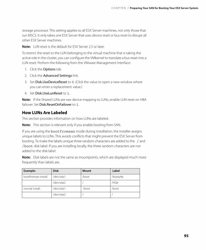
C H A P T E R 7 Preparing Your SAN for Booting Your ESX Server System
95
storage processor. This setting applies to all ESX Server machines, not only those that run MSCS. It only takes one ESX Server that uses device reset or bus reset to disrupt all other ESX Server machines.
Note: LUN reset is the default for ESX Server 2.5 or later.
To restrict the reset to the LUN belonging to the virtual machine that is taking the active role in the cluster, you can configure the VMkernel to translate a bus reset into a LUN reset. Perform the following from the VMware Management Interface:
1. Click the Options tab.
2. Click the Advanced Settings link.
3. Set Disk.UseDeviceReset to 0. (Click the value to open a new window where you can enter a replacement value.)
4. Set Disk.UseLunReset to 1.
Note: If the Shared LUNs are raw device mapping to LUNs, enable LUN reset on HBA failover. Set Disk.ResetOnFailover to 1.
How LUNs Are Labeled This section provides information on how LUNs are labeled.
Note: This section is relevant only if you enable booting from SAN.
If you are using the bootfromsan mode during installation, the installer assigns unique labels to LUNs. This avoids conflicts that might prevent the ESX Server from booting. To make the labels unique three random characters are added to the / and /boot disk label. If you are installing locally, the three random characters are not added to the disk label.
Note: Disk labels are not the same as mountpoints, which are displayed much more frequently than labels are.
Example: Disk Mount Label
bootfromsan install: /dev/sda1: /boot /booty4p
/dev/sda2: / /HQe
normal install: /dev/sda1: /boot /boot
/dev/sda2: / /
www.vmware.com96
VMware ESX Server SAN Configuration Guide
Configuring VMFS Volumes on SANsYou can use the VMware Management Interface to configure the SAN and format the VMFS-2 volumes. When you do so, make sure that only one ESX Server system has access to the SAN. After you have finished the configuration, make sure that all partitions on the physically shared SAN disk are set for public or shared access for access by multiple ESX Server systems.
Maximum Number of VMFS VolumesESX Server supports up to 128 LUNs. This includes both local volumes and LUNs visible on a SAN. If there is a large number of visible LUNs, the number could exceed the limit.
If there are more than 128 LUNs, you have the following options, discussed below:
• Using LUN Masking or Zoning
• Using the Disk.MaxLun Parameter
• Using the Disk.MaxLun Parameter with Multiple FC HBAs
Using LUN Masking or ZoningYou can use LUN masking or zoning to prevent the server from seeing LUNs it doesn't need to access. How you do this depends on the type of storage array and the management software used with it.
Using the Disk.MaxLun ParameterYou can reduce the number of visible LUNs by setting the Disk.MaxLUN VMKernel configuration parameter to a number smaller than 127. You can modify the parameter using the VMware Management Interface:
1. Click the Options tab, then the Advanced Settings link.
2. Scroll to the Disk.MaxLUN parameter.
3. Click the current value for update access.
If you have local disk volumes, reduce the number accordingly. For example, if you have two local LUNs and more than 126 LUNs on a SAN, you can limit visibility to 126 LUNs with this parameter: Disk.MaxLUN = 125
Using the Disk.MaxLun Parameter with Multiple FC HBAsThe Disk.MaxLUN parameter applies to each Fibre Channel host bus adapter (FC HBA), while the limit on LUNs applies to the entire server. If you have more than one FC HBA on the server, you need to divide by the number of FC HBAs so that the total number of LUNs visible from the server does not exceed 128.
C H A P T E R 7 Preparing Your SAN for Booting Your ESX Server System
97
To extend the example, suppose you have two FC HBAs instead of one. You need to set: Disk.MaxLUN = 62
The general formula is: ( (128 - #local_disks) / #FC_HBAs) - 1
Using Disk.MaxLUN makes sense when none of your FC HBAs needs to access the higher-numbered LUNs available on the SAN. If you require access to the higher-numbered LUNs, VMware recommends the use of LUN masking or zoning instead.
Note: Larger values of Disk.MaxLUN result in longer rescan times. Reducing the value can shorten the rescan time, which also allows the system to boot faster. The time to rescan LUNs depends on several factors, including the type of storage array and whether sparse LUN support is enabled.

www.vmware.com98
VMware ESX Server SAN Configuration Guide
C H A P T E R 8
99
Installing ESX Server on Storage Area Networks (SANs)
ESX Server supports installing and booting from Storage Area Networks (SANs), using either the graphical installer or the text-mode installer.
Before deploying ESX Server on Storage Area Networks (SANs), please check the latest version of the ESX Server SAN Compatibility Guide from the VMware Web site at www.vmware.com/pdf/esx_SAN_guide.pdf.
The sections in the chapter are:
• Preparing to Install ESX Server with SAN on page 100
• Installation Options on page 101
• Changing VMkernel Configuration Options for SANs on page 102
www.vmware.com100
VMware ESX Server SAN Configuration Guide
Preparing to Install ESX Server with SANThis section describes tasks required before you install your ESX Server.
If you are installing ESX Server without boot from SAN, be aware of the following:
• The ESX Server system must be installed on local storage with a SAN attached.
• VMware recommends that all Fibre Channel adapters are dedicated exclusively to the virtual machines. Even though these Fibre Channel adapters are dedicated to virtual machines, the LUNs on the SANs are visible to system management agents on the service console.
Caution: This version of ESX Server does not support MSCS clustering on IBM Shark storage servers. VMware recommends that online maintenance not be performed on the IBM Enterprise Storage Server when attached to ESX Server 2.5 with MSCS clustered Windows virtual machines.
If you are installing ESX Server for boot from SAN, perform these tasks:
1. If you are using IBM eserver BladeCenter servers, disconnect or disable all local IDE disks.
IBM server's IDE controllers must be disabled in order for boot from SAN to work. The IBM blade's BIOS does not allow the user to set the disk controller boot order, therefore if the IDE controllers are enabled, the system always tries to boot from the IDE drive.
2. Configure LUN masking on your SAN to ensure the following:
• Each ESX server has a dedicated LUN for the boot partition, which is not visible to other servers. This includes the /boot and the / partitions.
• /boot must be on /dev/sda.
• For configurations where more than one server is booting from the same SAN, you must ensure that all boot LUNs are configured with LUN numbers lower than any shared LUNs visible to multiple servers.
This means that typically, the boot LUN must be the lowest visible LUN. The exception is where ghost disks or gatekeeper disks use the lowest visible LUN.
3. Core dump and swap partitions can be put on the same LUN as the boot partition. Core dumps are stored in core dump partitions and swap files are stored in VMFS partitioned space.
C H A P T E R 8 Installing ESX Server on Storage Area Networks (SANs)
101
Installation OptionsThe installation options available from the ESX Server installation boot screen include:
• Press enter — proceeds with the standard ESX Server installation using a GUI interface.
• noapic — disables the apic mode.
• text — uses the text installation interface rather than the GUI.
• driver disk —prompts for the ESX Server driver disk. Used to install drivers for supported hardware for the current ESX Server release.
• bootfromsan — installs ESX Server on a Storage Area Network (SAN) using the standard graphical, mouse-based installation program.
• bootfromsan-text — installs ESX Server on a Storage Area Network (SAN) using a text-based interface.
Refer to your VMware ESX Server Installation Guide for installation information.
www.vmware.com102
VMware ESX Server SAN Configuration Guide
Changing VMkernel Configuration
Options for SANsIn order to use all storage devices on your SAN, after you have installed ESX Server, you can change some VMkernel configuration options.
To make these changes, complete the following steps.
1. Log on to the VMware Management Interface as root.
The Status Monitor page appears.
2. Click the Options tab.
3. Click Advanced Settings.
4. To change an option, click the current value, then enter the new value in the dialog box and click OK.
Detecting All LUNsBy default, the VMkernel scans for only LUN 0 to LUN 7 for every target. If you are using LUN numbers larger than 7 you must change the setting for the Disk.MaxLUN field from the default of 8 to the value that you need. For example, if LUN number 0 -15 are active, set this option to 15. This scans 0 - 15, a total of 16 LUNs. Currently, an ESX Server machine can see a maximum of 128 LUNs over all disk arrays on a SAN.
By default, the VMkernel is configured to support sparse LUNs — that is, a case where some LUNs in the range 0 to N-1are not present, but LUN N is present. If you do not need to use such a configuration, you can change the DiskSupportSparseLUN field to 0. This change decreases the time needed to scan for LUNs.
The DiskMaskLUNs configuration option allows the masking of specific LUNs on specific HBAs. Masked LUNs are not touched or accessible by the VMkernel, even during initial scanning. The DiskMaskLUNs option takes a string comprised of the adapter name, target ID and comma-separated range list of LUNs to mask. The format is as follows:
<adapter>:<target>:<comma_separated_LUN_range_list>;
For example, you want to mask LUNs 4, 12, and 54-65 on vmhba 1 target 5, and LUNs 3-12, 15, and 17-19 on vmhba 3 target 2. To accomplish this, set the DiskMaskLUNs option to the following:
"vmhba1:5:4,12,54-65;vmhba3:2:3-12,15,17-19;"
C H A P T E R 8 Installing ESX Server on Storage Area Networks (SANs)
103
Note: LUN 0 cannot be masked. Refer to your VMware Management Interface documentation for information on changing the settings using the DiskMaskLuns option.
The DiskMaskLUNs option subsumes the Disk.MaxLUN option for adapters that have a LUN mask. In other words, continuing the preceding example:
• There are four adapters, vmhba0, vmhba1, vmhba2, and vmhba3
• The Disk.MaxLUN option is set to 8.
In this example
• vmhba0 and vmhba2 only scan LUNs 0-7.
• vmhba1 and vmhba3 scan all LUNs that are not masked, up to LUN 255, or the maximum LUN setting reported by the adapter, whichever is less.
For administrative or security purposes, you can use LUN masking to prevent the server from seeing LUNs that it doesn’t need to access. Refer to your documentation on disk arrays for more information.
Checking LUN StatusYou can view LUNs using the VMware Management Interface or by viewing the output of ls /proc/vmware/scsi/<FC_SCSI_adapter>. If the output differs from what you expect, then check the following:
• Disk.MaxLUN — the maximum number of LUNs per vmhba that are scanned by ESX Server.
You can view and set this option through the VMware Management Interface (Options > Advanced Settings) or by viewing this setting through/proc/vmware/config/Disk/MaxLUN.
• DiskSupportSparseLUN — if this option is on, then ESX Server scans past any missing LUNs. If this option is off, ESX Server stops scanning for LUNs if any LUN is missing.
You can view and set this option through the VMware Management Interface (Options > Advanced Settings) or by viewing this setting through/proc/vmware/config/Disk/SupportSparseLUN.
• LUN masking — With LUN masking, each LUN is exclusively assigned and accessed by a specific list of connections. Be sure that LUN masking is implemented properly and that the LUNs are visible to the HBAs on ESX Server.

www.vmware.com104
VMware ESX Server SAN Configuration Guide
C H A P T E R 9
105
Post-Boot ESX Server SAN Considerations
After you have successfully configured and booted your ESX Server, consider setting and adjusting the following:
• Reviewing LUN Status on page 106
• Failover Expectations on page 107
• Viewing Failover Paths Connections on page 108
Note: When adding more LUNs or changing zoning in a boot from SAN configuration, ensure that the boot LUN is always the lowest visible LUN.
Note: When reconfiguring your Fibre Channel network, consider the impact on your running ESX Server machines.
www.vmware.com106
VMware ESX Server SAN Configuration Guide
Reviewing LUN StatusYou can view LUNs using the VMware Management Interface or by examining the output of vmkpcidivy -q vmhba-devs. If the output differs from what you expect, check the following:
• Zoning — Zoning limits access to specific storage devices, increases security, and decreases traffic over the network. If you use zoning, make sure that zoning on the SAN switch is set up properly and that all vmhba and the controllers of the disk array are in the same zone.
• LUN masking — Ensure that each ESX Server sees only required LUNs. Particularly, do not allow any ESX Server to see any boot LUN other than its own.
• Storage controller — If a disk array has more than one storage controller, make sure that the SAN switch has a connection to the controller that owns the LUNs you wish to access. On some disk arrays, only one controller is active and the other controller is passive until there is a failure. If you are connected to the wrong controller (the one with the passive path) you may not see the expected LUNs or you may see the LUNs, but may get errors when trying to access them.
For more information on using SANs with ESX Server, be sure to check the Knowledge Base on the VMware Web site at www.vmware.com/support/kb/enduser/std_alp.php.
Note: If you are using QLogic HBAs, do the following:
1. Clear the cache to remove pseudo LUNs.
2. Perform a SAN rescan using the following syntax:
[root@esx /]# "echo "scsi-qlascan" > /proc/scsi/qlaxxxx/y"
(xxxx is the model/driver number and y is the adapter number)
For example:
[root@esx /]# "echo "scsi-qlascan" > /proc/scsi/qla2300/0"
That command clears the cache from QLogic 2300 HBA #0.
C H A P T E R 9 Post-Boot ESX Server SAN Considerations
107
Failover ExpectationsWhen a SAN cable is pulled, I/O freezes for approximately 30-60 seconds, until the SAN driver determines that the link is down, and failover occurs. During that time, the virtual machines (with their virtual disks installed on a SAN) may appear unresponsive, and any operations on the /vmfs directory may appear to hang. After the failover occurs, I/O should resume normally.
In case of disastrous events that include multiple breakages, all connections to SAN devices might be lost. If all connections to the storage device are not working, the virtual machines begin to encounter I/O errors on their virtual SCSI disks. Operations in the /vmfs directory might eventually fail after reporting an I/O error.

www.vmware.com108
VMware ESX Server SAN Configuration Guide
Viewing Failover Paths Connections The Failover Paths page allows you to examine the current state of paths between your system and SAN LUNs. Multipathing support allows your system to maintain a constant connection between the server machine and the storage device in case of the failure of a host bus adapter (HBA), switch, storage controller, or Fibre Channel cable.
For each SAN Logical Unit Number (LUN), this page displays the available paths and the preferred path.
ESX Server does not perform I/O load balancing across paths. At any one time, only a single path is used to issue I/O to a given LUN. This path is known as the active path.
• If the path policy of a LUN is set to FIXED, ESX Server selects the path marked as preferred as the active path.
If the preferred path is disabled or unavailable, an alternate working path is used as the active path.
• If the path policy of a LUN is set to MRU, ESX Server selects an active path to the LUN that prevents path thrashing. The preferred path designation is not considered.
C H A P T E R 9 Post-Boot ESX Server SAN Considerations
109
From a SAN point of view, the term active means any path that is available for issuing I/O to a LUN. From an ESX Server point of view, the term active means the one and only path that ESX Server is using to issue I/O to a LUN.
For the command-line equivalent, use:
vmkmultipath -q
The failover paths show the adapter, the target, the LUN, and the SAN target for the LUN. Each SAN target is identified by its World Wide Port Name.
A symbol indicates the current status of each path:
— The path is active and data is being transferred successfully.
— The path is set to disabled and is available for activation.
— The path should be active, but the software cannot connect to the LUN through this path.
If you have configured a LUN to use a preferred path, that path is identified with the label Preferred after the SAN Target listing.
If a SAN array has both active and passive paths (such as the IBM FAStT or the EMC CLARiiON) a single active path to the LUN is marked by ESX Server as the currently active path. This means that ESX Server is using that path to issue I/O to the LUN. All other paths that are active or passive are indicated by the ESX Server as available (marked with an uncolored/empty triangle).

www.vmware.com110
VMware ESX Server SAN Configuration Guide

111
IndexA
adding a LUN 93
B
BIOSEmulex HBA 69QLogic HBA 66
boot from SAN 90preparing ESX Server 87
boot loader 81
boot partition 90
boot path 90configuring 90
C
checking LUN labels 95
checking LUN status 103
clusteringFAStT 73IBM TotalStorage 73
configuringboot loader 81boot path 90gatekeeper 80LUN reset 78, 94multipath information 76storage processor port 74storage processor sense data 75VMFS volumes 96VMkernel 102
D
Dell/EMC Fibre Channel 83
detecting LUNs 102
E
EMC CLARiiON 82
EMC Symmetrix 80
Emulexconfiguration for SAN 69
F
failoverFAStT storage 74path connections 108post boot 107
FAStT
configuring for clustering 73
G
gatekeeper 80changing LUN number 80
H
HBAEmulex 69QLogic 66rescanning 94
HP StorageWorks 83, 84
I
IBM TotalStorageconfiguring for clustering 73
installingoptions 101preparing for boot from SAN 88
L
LUNadding a new 93changing gatekeeper 80checking labels 95checking status 103detecting 102reset 78, 94review post boot status 106scanning for devices 93Symmetrix gatekeeper 80visibility 93
M
multipathviewing configuration 76
P
persistent bindings 77
planning LUN visibility 93
post bootfailover expectations 107failover path connections 108LUN status 106
Q
QLogicconfiguration for SAN 66
R
www.vmware.com112
rescanning 94
resetting persistent bindings 77
S
SANhardware failover 74preparing ESX Server 87preparing to install ESX Server 88
scanning for devices 93
storage processorconfiguring sense data 75port configuration 74
storage systemDell/EMC Fibre Channel 83EMC CLARiiON 82EMC Symmetrix 80HP Storage Works 83HP StorageWorks 84
V
VMFS volumes 96maximum number 96
VMkernel configuration 102