vo-540, ivo-540, tivo-540 series · 2017-03-14 · operator s manual lycoming vo-540, ivo-540,...
TRANSCRIPT

Operator�s Manual
Lycoming
VO-540, IVO-540,
TIVO-540 Series
Approved by FAA
2nd Edition Part No. 60297-17
652 Oliver StreetWilliamsport, PA. 17701 U.S.A.570/323-6181
May 2008
VO-540, IVO-540, TIVO-540 Series Operator�s Manual Lycoming Part Number: 60297-17
©2008 by Lycoming. All rights reserved.Lycoming and �Powered by Lycoming� are trademarks or registered trademarks of Lycoming.
All brand and product names referenced in this publication are trademarks or registeredtrademarks of their respective companies.
For additional information:
Mailing address:
Lycoming Engines652 Oliver StreetWilliamsport, PA 17701 U.S.A.
Phone:
Factory: 570-323-6181Sales Department: 570-327-7268Fax: 570-327-7101
Lycoming�s regular business hours are Monday through Friday from 8:00 AMthrough 5:00 PM Eastern Time (-5 GMT)
Visit us on the World Wide Web at:http://www.lycoming.com
LYCOMING OPERATOR�S MANUAL
ATTENTION
OWNERS, OPERATORS, AND MAINTENANCE PERSONNEL
This operator�s manual contains a description of the engine, its specifications, and detailed information onhow to operate and maintain it. Such maintenance procedures that may be required in conjunction withperiodic inspections are also included. This manual is intended for use by owners, pilots and maintenancepersonnel responsible for care of Lycoming powered aircraft. Modifications and repair procedures arecontained in Lycoming overhaul manuals; maintenance personnel should refer to these for such procedures.
SAFETY WARNING
Neglecting to follow the operating instructions and to carry out periodic maintenance procedures can resultin poor engine performance and power loss. Also, if power and speed limitations specified in this manualare exceeded, for any reason, damage to the engine and personal injury can happen. Consult your localFAA approved maintenance facility.
SERVICE BULLETINS, INSTRUCTIONS, AND LETTERS
Although the information contained in this manual is up-to-date at time of publication, users are urged tokeep abreast of later information through Lycoming Service Bulletins, Instructions and Service Letterswhich are available from all Lycoming distributors or from the factory by subscription. Consult the latestrevision of Service Letter No. L114 for subscription information.
SPECIAL NOTE
The illustrations, pictures and drawings shown in this publication are typical of the subject matter theyportray; in no instance are they to be interpreted as examples of any specific engine, equipment or partthereof.
iii
LYCOMING OPERATOR�S MANUAL
IMPORTANT SAFETY NOTICE
Proper service and repair is essential to increase the safe, reliable operation of all aircraft engines. Theservice procedures recommended by Lycoming are effective methods for performing service operations.Some of these service operations require the use of tools specially designed for the task. These special toolsmust be used when and as recommended.
It is important to note that most Lycoming publications contain various Warnings and Cautions whichmust be carefully read in order to minimize the risk of personal injury or the use of improper servicemethods that may damage the engine or render it unsafe.
It is also important to understand that these Warnings and Cautions are not all inclusive. Lycoming couldnot possibly know, evaluate or advise the service trade of all conceivable ways in which service might bedone or of the possible hazardous consequences that may be involved. Accordingly, anyone who uses aservice procedure must first satisfy themselves thoroughly that neither their safety nor aircraft safety will bejeopardized by the service procedure they select.
iv
LYCOMING OPERATOR�S MANUAL
TABLE OF CONTENTS
Page
SECTION 1 DESCRIPTION 1-1
SECTION 2 SPECIFICATIONS 2-1
SECTION 3 OPERATING INSTRUCTIONS 3-1
SECTION 4 PERIODIC INSPECTIONS 4-1
SECTION 5 MAINTENANCE PROCEDURES 5-1
SECTION 6 TROUBLE-SHOOTING 6-1
SECTION 7 INSTALLATION AND STORAGE 7-1
SECTION 8 TABLES 8-1
V
LYCOMING OPERATOR�S MANUAL
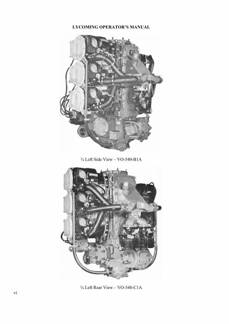
¾ Left Side View � VO-540-B1A
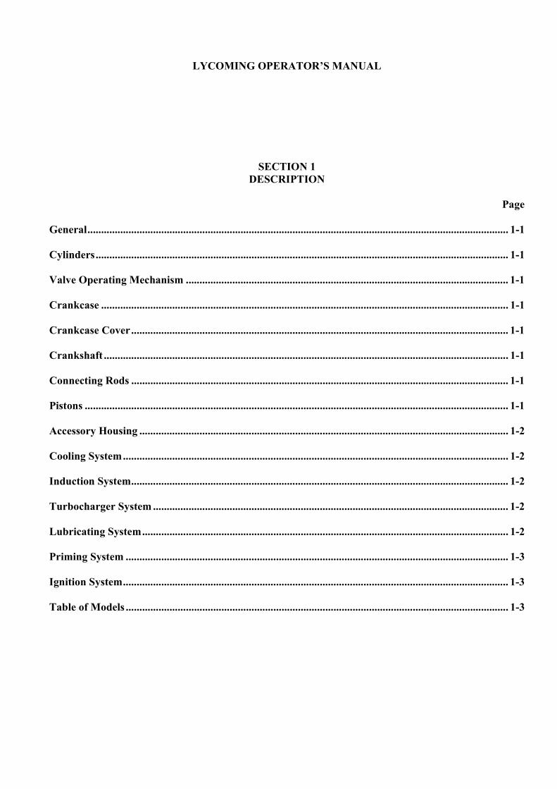
¾ Left Rear View � VO-540-C1A vi
LYCOMING OPERATOR�S MANUAL
SECTION 1DESCRIPTION
Page
General.......................................................................................................................................................... 1-1
Cylinders....................................................................................................................................................... 1-1
Valve Operating Mechanism ...................................................................................................................... 1-1
Crankcase ..................................................................................................................................................... 1-1
Crankcase Cover.......................................................................................................................................... 1-1
Crankshaft .................................................................................................................................................... 1-1
Connecting Rods .......................................................................................................................................... 1-1
Pistons ........................................................................................................................................................... 1-1
Accessory Housing ....................................................................................................................................... 1-2
Cooling System............................................................................................................................................. 1-2
Induction System.......................................................................................................................................... 1-2
Turbocharger System .................................................................................................................................. 1-2
Lubricating System...................................................................................................................................... 1-2
Priming System ............................................................................................................................................ 1-3
Ignition System............................................................................................................................................. 1-3
Table of Models ............................................................................................................................................ 1-3

This Page Intentionally Left Blank.
LYCOMING OPERATOR�S MANUAL SECTION 1 VO, IVO & TIVO-540 SERIES DESCRIPTION
SECTION 1
DESCRIPTION
Lycoming VO-540, IVO-540 and TIVO-540 series engines are six cylinder, horizontally opposed, drysump, air cooled models designed for installation in rotor driven aircraft.
In referring to the location of various engine components, the parts will be described in their relationshipto the engine as installed in the airframe. Thus the power take-off section is considered the top and theaccessory drive section the bottom. The section where the shroud tubes are located is the front and theopposite section the rear. References to the left and right side of the engine are made with the observerstanding at the rear and facing front. The cylinders are numbered from top to bottom; odd numberedcylinders on the left, even numbered cylinders on the right.
The direction of rotation of the crankshaft is clockwise viewed from the bottom of the engine. For allaccessory drives, the direction of rotation is determined when facing the drive pad.
Cylinders � The cylinders are of conventional air cooled construction with the two major parts, head andbarrel, screwed and shrunk together. The heads are made from an aluminum alloy casting with a fullymachined combustion chamber. Rocker shaft bearing supports are cast integral with the head along withhousings to form the rocker boxes for both valve rockers. The cylinder barrels, which are machined fromchrome nickel molybdenum steel forgings, have deep integral cooling fins and the inside of the barrels areground and honed to a specified finish.
Valve Operating Mechanism � A conventional type camshaft is located in front of and parallel to thecrankshaft. The camshaft actuates hydraulic tappets which operate the valves through push rods and valverockers. The valve rockers are supported on full floating steel shafts. The valve springs bear againsthardened steel seats and are retained on the valve stems by means of split keys.
Crankcase � The crankcase assembly consists of two reinforced aluminum alloy castings fastened togetherby means of studs, bolts and nuts. The mating surfaces of the two castings are joined without the use of agasket and the main bearing bores are machined for use of precision type main bearing inserts.
Crankcase Cover � The crankcase cover is made from a magnesium alloy casting and is fastened to the rearof the crankcase. An integral cast chamber incorporates a mounting pad for the carburetor or fuel injectorand serves as a center distributing zone for the fuel � air mixture on carbureted engines.
Crankshaft � The crankshaft is made from a chrome nickel molybdenum steel forging. All bearing journalsurfaces are nitrided.
Connecting Rods � The connecting rods are made in the form of �H� sections from alloy steel forgings. They have replaceable bearing inserts in the crankshaft ends and bronze bushings in the piston ends. Thebearing caps on the crankshaft ends are retained by means of two bolts and nuts through each cap.
Pistons � The pistons are machined from an aluminum alloy forging. The piston pin is of the full floatingtype with a plug located at each end. Depending on the cylinder assembly, pistons may be machined foreither three or five rings and employ half wedge rings. Consult the latest revision of Service Instruction No.1037 for proper piston and ring assemblies.
1-1
SECTION 1 LYCOMING OPERATOR�S MANUAL DESCRIPTION VO, IVO & TIVO-540 SERIES
Accessory Housing � The accessory housing and accessory housing cover are made from magnesium alloycastings and are fastened to the bottom of the crankcase. This assembly forms a housing for the oil pumpand the various accessory drives. A scavenge oil sump is fastened to the bottom of the accessory housing.
Cooling System � The engine is designed to be cooled by air pressure built up on one side of the cylinderand discharged, with an accompanying drop in pressure, through cylinder finning. This cooling air on rotor-driven aircraft is supplied by an external fan installed by the airframe manufacturer. Close fitting bafflesdirect the flow of air around the cylinder fins and the discharge air is exhausted to the atmosphere.
Induction System (Carbureted Engines) � These engines are equipped with either single or dual MA-6-AAcarburetors (see Table of Models for model application). This carburetor incorporates an automatic mixturecontrol and idle-cut-off. The fuel � air mixture, after passing from the carburetor to the center distributingzone is distributed to the cylinders through individual intake pipes.
Induction System (Fuel Injected Engines) � (See Table of Models for model application.) Either a BendixRS system or RSA system is used on subject engines.
The RS system operates by measuring the air flow through the throttle body of the servo valve regulatorcontrols, and uses this measurement to operate a servo valve within the control. The regulated pressureestablished by the servo valve is used to control the fuel distributor valve assembly, which then establishesfuel flow in proportion to air flow and fuel vaporization takes place at the individual intake port.
The RSA system is based on the principle of measuring air flow and using the air flow signal in a stemtype regulator to convert the air force into a fuel force. This fuel force (fuel pressure differential) whenapplied across the fuel metering section makes fuel flow proportional to air flow. Vaporization takes placeat individual intake ports.
Turbocharger System (TIVO-540) � A turbocharger is supplied as an integral part of the TIVO-540 model.The function of the turbocharger is to provide constant air density to the fuel injector inlet from sea level tocritical altitude. Regulating the amount of exhaust gas fed to the turbine wheel controls the output whichdetermines engine power. This factor is regulated by the control system which has two components, namelythe density controller and the exhaust bypass valve (waste gate). The position of the waste gate isdetermined by oil pressure acting on a piston which is connected to the butterfly valve by linkage.Increasing oil pressure on the piston closes the waste gate valve and increases power; decreasing oilpressure opens the valve and decreases power. The bleed oil required to activate the piston is controlled bythe density controller. The density controller action is automatic and modulating to continue and reverse theprocess as engine power, speed and altitude change.
Lubricating System � The dry sump, fuel pressure lubrication system is actuated by an impeller type oilpump enclosed within the accessory housing. This pump incorporates a pressure pump and a scavenge pumpdriven by a common drive shaft. The pressure pump draws oil from the externally mounted supply tank andforces it through drilled passages to the oil filter. From the filter the oil is directed through a check valve tothe oil pressure regulating valve. The check valve prevents gravity oil from draining into the crankcasewhen the engine is shut down and the oil pressure valve maintains the oil pressure within limits anddischarges excess oil back to the inlet side of the pump. After completing its passage through the engine theoil is conducted to the scavenge pump in the accessory housing and returned to the external tank.
1-2

LYCOMING OPERATOR�S MANUAL SECTION 1 VO, IVO & TIVO-540 SERIES DESCRIPTION
Priming System � Provision for a priming system is provided on all carbureted engines. Fuel injectedengines do not require a priming system.
Ignition System � Dual ignition is furnished by magnetos assembled on each side of the accessory housing.Consult Table of Models for model application.
TABLE OF MODELS
MODEL APPLICATION
Model* Left Right Carburetor Fuel InjectorVO-540-B1A, -B2AVO-540-B1B, -B1FVO-540-B1C, -B2CVO-540-B1D, -B2DVO-540-B1E, -B2EVO-540-B2GVO-540-B1B3VO-540-B1H3VO-540-C1A, -C2AVO-540-C1B, -C2BVO-540-C2CVO-540-C1C3IVO-540-A1ATIVO-540-A2A
S6LN-20S6LN-204S6LN-204S6LN-204S6LN-20S6LN-1209S6LN-204S6LN-1209S6LN-204S6LN-20S6LN-1209S6LN-204S6LN-204S6LN-204
S6RN-21S6RN-200S6RN-200S6RN-200S6RN-21S6RN-1208S6RN-200S6RN-1208S6RN-200S6RN-21S6RN-1208S6RN-200S6RN-200S6RN-200
MA-6AAMA-6AAMA-6AAMA-6AA(2)MA-6AA(2)MA-6AA(2)MA-6AAMA-6AAMA-6AA(2)MA-6AA(2)MA-6AA(2)MA-6AA(2)
RSA-10AD1RS-5BD2
* - Models with number 2 in suffix incorporate spring coupling drives. Models withnumber 3 in suffix incorporate counterweighted crankshaft.
1-3

This Page Intentionally Left Blank.
LYCOMING OPERATOR�S MANUAL
SECTION 2SPECIFICATIONS
Page
Specifications � VO-540-B Series ............................................................................................................... 2-1
Specifications � VO-540-C Series ............................................................................................................... 2-1
Specifications � IVO-540 Series.................................................................................................................. 2-2
Specifications � TIVO-540 Series ............................................................................................................... 2-2
Accessory Drives .......................................................................................................................................... 2-3
Detail Weights .............................................................................................................................................. 2-3

This Page Intentionally Left Blank.
LYCOMING OPERATOR�S MANUAL SECTION 2 VO, IVO & TIVO-540 SERIES SPECIFICATIONS
SECTION 2
SPECIFICATIONS
VO-540-B SERIES
FAA Type Certificate ....................................................................................................................................304Rated horsepower...........................................................................................................................................305Rated speed, RPM........................................................................................................................................3200Bore, inches.................................................................................................................................................5.125Stroke, inches..............................................................................................................................................4.375Displacement, cubic inches.........................................................................................................................541.5Compression ratio ....................................................................................................................................... 7.3:1Firing order .......................................................................................................................................1-4-5-2-3-6Spark occurs, degrees BTC..............................................................................................................................25Valve rocker clearance (hydraulic tappets collapsed) ......................................................................... .028-.080Crankshaft drive ratio .................................................................................................................................... 1:1Crankshaft rotation (viewed from bottom) .........................................................................................Clockwise
VO-540-C SERIES
FAA Type Certificate ....................................................................................................................................304Rated horsepower...........................................................................................................................................305Rated speed, RPM........................................................................................................................................3200Bore, inches.................................................................................................................................................5.125Stroke, inches..............................................................................................................................................4.375Displacement, cubic inches.........................................................................................................................541.5Compression ratio ....................................................................................................................................... 8.7:1Firing order .......................................................................................................................................1-4-5-2-3-6Spark occurs, degrees BTC..............................................................................................................................25Valve rocker clearance (hydraulic tappets collapsed) ......................................................................... .028-.080Crankshaft drive ratio .................................................................................................................................... 1:1Crankshaft rotation (viewed from bottom) .........................................................................................Clockwise
2-1
SECTION 2 LYCOMING OPERATOR�S MANUAL SPECIFICATIONS VO, IVO & TIVO-540 SERIES
SPECIFICATIONS
IVO-540 SERIES
FAA Type Certificate ..............................................................................................................................E11EARated horsepower...........................................................................................................................................305Rated speed, RPM........................................................................................................................................3200Bore, inches.................................................................................................................................................5.125Stroke, inches..............................................................................................................................................4.375Displacement, cubic inches.........................................................................................................................541.5Compression ratio ....................................................................................................................................... 8.7:1Firing order .......................................................................................................................................1-4-5-2-3-6Spark occurs, degrees BTC..............................................................................................................................25Valve rocker clearance (hydraulic tappets collapsed) ......................................................................... .028-.080Crankshaft drive ratio .................................................................................................................................... 1:1Crankshaft rotation (viewed from bottom) .........................................................................................Clockwise
TIVO-540 SERIES
FAA Type Certificate ................................................................................................................................. 1E14Rated horsepower...........................................................................................................................................315Rated speed, RPM........................................................................................................................................3200Bore, inches.................................................................................................................................................5.125Stroke, inches..............................................................................................................................................4.375Displacement, cubic inches.........................................................................................................................541.5Compression ratio ....................................................................................................................................... 7.3:1Firing order .......................................................................................................................................1-4-5-3-2-6Spark occurs, degrees BTC..............................................................................................................................25Valve rocker clearance (hydraulic tappets collapsed) ......................................................................... .028-.080Crankshaft drive ratio .................................................................................................................................... 1:1Crankshaft rotation (viewed from bottom) .........................................................................................Clockwise
2-2
LYCOMING OPERATOR�S MANUAL SECTION 2 VO, IVO & TIVO-540 SERIES SPECIFICATIONS
SPECIFICATIONS
Accessory Drives Drive Ratio Direction of Rotation
Starter, electricStarter, manual*GeneratorMagnetos S6LNMagnetos S6RNFuel pumpVacuum pumpHydraulic pumpTachometer
1.000:12.600:12.600:11.500:11.500:10.803:11.219:11.083:10.500:1
ClockwiseClockwiseClockwiseClockwise
CounterclockwiseCounterclockwise
ClockwiseClockwise
Counterclockwise
* - Inoperative as generator drive when hand crank is installed.
DETAIL WEIGHTS
1. STANDARD ENGINE, DRY WEIGHT
MODEL LBS.
VO-540-B1B.............................................................................................................................................429.00VO-540-B1A, -B1C, -B1F........................................................................................................................430.00VO-540-B2A, -B2C..................................................................................................................................433.00IVO-540-A1A...........................................................................................................................................435.00VO-540-B1D, -B1E ..................................................................................................................................439.00VO-540-C1A, -C2A..................................................................................................................................441.00VO-540-B2D, -B2E ..................................................................................................................................442.00VO-540-B2G.............................................................................................................................................443.00VO-540-C2A, -C2B, -B1B3 .....................................................................................................................444.00VO-540-C2C, -B1H3................................................................................................................................445.00VO-540-C1C3...........................................................................................................................................453.00
Above weight includes carburetor or fuel injector, magnetos, spark plugs, ignition harness, priming system(where applicable), and inter-cylinder baffles.
TIVO-540-A2A.........................................................................................................................................507.00
Above weight includes fuel injector, magnetos, spark plugs, ignition harness, turbocharger controls, oillines and baffles.
2-3

This Page Intentionally Left Blank.
LYCOMING OPERATOR�S MANUAL
SECTION 3OPERATING INSTRUCTIONS
Page
General.......................................................................................................................................................... 3-1
Prestarting Items of Maintenance .............................................................................................................. 3-1
Starting Procedures
Carbureted Engines .................................................................................................................................. 3-1
Fuel Injected Engines ............................................................................................................................... 3-2
Cold Weather Starting ................................................................................................................................ 3-2
Ground Running and Warm-Up................................................................................................................ 3-3
Checks Before Take-Off .............................................................................................................................. 3-3
Operation in Flight
Use of Carburetor Heat Control.............................................................................................................. 3-4
Fuel Mixture Leaning Procedure ............................................................................................................ 3-5
Engine Shut-Down ....................................................................................................................................... 3-5
Engine Flight Chart ..................................................................................................................................... 3-5
Operating Conditions .................................................................................................................................. 3-6
Performance Curves .................................................................................................................................... 3-8

This Page Intentionally Left Blank.
LYCOMING OPERATOR�S MANUAL SECTION 3 VO, IVO & TIVO-540 SERIES OPERATING INSTRUCTIONS
SECTION 3
OPERATING INSTRUCTIONS
1. GENERAL. Close adherence to these instructions will greatly contribute to long life, economy andsatisfactory operation of the engine.
NOTE
YOUR ATTENTION IS DIRECTED TO THE WARRANTIES THAT APPEAR IN THEFRONT OF THIS MANUAL REGARDING ENGINE SPEED, THE USE OF SPECIFIEDFUELS AND LUBRICANTS, REPAIRS AND ALTERATIONS. PERHAPS NO OTHER ITEMOF ENGINE OPERATION AND MAINTENANCE CONTRIBUTES QUITE SO MUCH TOSATISFACTORY PERFORMANCE AND LONG LIFE AS THE CONSTANT USE OFCORRECT GRADES OF FUEL AND OIL, CORRECT ENGINE TIMING, AND FLYINGTHE AIRCRAFT AT ALL TIMES WITHIN THE SPEED AND POWER RANGE SPECIFIEDFOR THE ENGINE. DO NOT FORGET THAT VIOLATION OF THE OPERATION ANDMAINTENANCE SPECIFICATIONS FOR YOUR ENGINE WILL NOT ONLY VOID YOURWARRANTY BUT WILL SHORTEN THE LIFE OF YOUR ENGINE AFTER ITS WARRANTYPERIOD HAS PASSED.
New engines have been carefully run-in by Lycoming and therefore no further break-in is necessaryinsofar as operation is concerned; however, new or newly overhauled engines should be operated using onlythe lubricating oils recommended in the latest revision of Service Instruction No. 1014.
NOTE
Cruising should be done at 65% to 75% power until a total of 50 hours has accumulated oroil consumption has stabilized. This is to insure proper seating of the piston rings and isapplicable to new engines, and engines in service following cylinder replacement or topoverhaul of one or more cylinders.
The minimum fuel octane rating is listed in the flight chart, Part 9 of this section. Under no circumstancesshould fuel of a lower octane rating or automotive fuel (regardless of octane rating) be used. Personnelshould be familiar with the latest revision of Service Instruction No. 1070.
2. PRESTARTING ITEMS OF MAINTENANCE. Before starting the aircraft engine for the first flight of theday, there are several items of maintenance inspection that should be performed. These are described inSection 4 under Daily Pre-Flight Inspection. They must be observed before the engine is started.
3. STARTING PROCEDURES (NORMAL).
a. Carbureted Engines.
(1) Perform pre-flight inspection.
(2) Carburetor heat �cold�.
(3) Turn fuel valve on.
3-1
SECTION 3 LYCOMING OPERATOR�S MANUAL OPERATING INSTRUCTIONS VO, IVO & TIVO-540 SERIES
(4) Place mixture control in �Full Rich�.
(5) Crack throttle to detent.
(6) Set magneto selector switch. Consult airframe manufacturer�s handbook for correct position.
(7) While cranking engine, prime just long enough to build fuel pressure to normal range.
(8) When engine starts, move magneto selector switch to �Both�.
(9) Set engine at fast idle, if oil pressure is not indicated within 30 seconds stop the engine anddetermine reason.
b. Fuel Injected Engines.
(1) Perform pre-flight inspection.
(2) Inlet heat �cold�.
(3) Turn fuel valve on.
(4) Turn on boost pump until a slight but steady flow is indicated.
(5) Move mixture control to idle cut-off.
(6) Crack throttle approximately 1/8 open.
(7) Set magneto selector switch. Consult airframe manufacturer�s handbook for correct position.
(8) Engage the starter switch.
(9) When engine starts, move the magneto selector switch to �Both�.
(10) Move mixture control slowly and steadily to �Full Rich�.
(11) Set engine at fast idle, if oil pressure is not indicated within 30 seconds, stop the engine anddetermine trouble.
WARNING
NEVER ATTEMPT TO HAND CRANK A HOT ENGINE. ALLOW THE ENGINE TO COOLFOR AT LEAST FIVE MINUTES BEFORE CRANKING.
4. COLD WEATHER STARTING. During cold weather it may be necessary to preheat the engine and oilbefore starting.
3-2
LYCOMING OPERATOR�S MANUAL SECTION 3 VO, IVO & TIVO-540 SERIES OPERATING INSTRUCTIONS
CAUTION
ENGINES EQUIPPED WITH PISTON OIL JETS � DURING EXTREME COLD WEATHER (-20°F AND BELOW) IT WILL BE NECESSARY TO PRE-HEAT THE ENGINE FOR ASUFFICIENT LENGTH OF TIME TO ALLOW THE HEAT TO PENETRATECRANKSHAFT AND LOOSEN CONGEALED OIL IN PASSAGES BETWEEN THE MAINBEARINGS AND CONNECTING ROD BEARINGS.
BECAUSE THE HEAT PENETRATES THE ALUMINUM CRANKCASE MORE RAPIDLYTHAN THE STEEL CRANKSHAFT, IT IS POSSIBLE FOR THE OIL TO CIRCULATEAROUND THE ANNULUS OF THE MAIN BEARING AND THROUGH THE PISTON OILJETS. THIS CIRCULATION, WHILE GIVING A SAFE READING ON THE OILTEMPERATURE AND OIL PRESSURE GAUGES, COULD OCCUR WITHOUTDISLODGING THE CONGEALED OIL IN THE CRANKSHAFT OIL PASSAGES,CAUSING OIL STARVATION TO THE CONNECTING ROD BEARINGS.
5. GROUND RUNNING AND WARM-UP.
a. Leave aircraft control in �Full Rich�.
b. Idle engine until oil pressure reaches 50 psi minimum. Consult airframe manufacturer�s handbook forrotor and engine speed.
c. Limit ground running to minimum time necessary to warm engine for take-off.
6. CHECKS BEFORE TAKE-OFF.
a. Check both oil temperature and oil pressure.
b. Set carburetor air heat control for �Full Heat� to check proper operation. Loss of RPM and manifoldpressure will result if heat control is working properly. Return heat control to �cold� position aftercheck.
c. With rotor angle at minimum pitch, increase RPM to 3200 and check magneto drop-off. Switch fromboth magnetos to one and note drop-off, return to both magnetos until engine regains speed and switchto the other magneto and note drop-off, then return to �both�. Drop-off should not exceed 200 RPMon either magneto and should be within 50 RPM of each other.
NOTE
Do not operate too long on one magneto, 2 to 3 seconds is sufficient and will minimize plugfouling.
3-3
SECTION 3 LYCOMING OPERATOR�S MANUAL OPERATING INSTRUCTIONS VO, IVO & TIVO-540 SERIES
a. Use of Carburetor Heat Control � Under certain moist atmospheric conditions, it is possible for ice toform in the induction system even in summer weather. This is due to the high air velocity through thecarburetor venturi and the absorption of heat from this air by evaporation of the fuel. The temperaturein the mixture chamber may drop 20°F to 70°F below the temperature of the incoming air. If this aircontains a large amount of moisture, the cooling process will cause precipitation in the form of ice.These ice formations generally begin in the vicinity of the butterfly throttle and will often build up tosuch an extent that engine operation is noticeably affected. This ice will obstruct the carburetorpassage resulting in a decreased flow of mixture and consequently a drop in manifold pressure andRPM. If not detected this condition will continue to such an extent that the reduced power will causecomplete engine stoppage.
To avoid this condition, all installations are equipped with a system for preheating the incoming airsupply to the carburetor. In this way, sufficient heat is added to replace the heat loss to vaporization offuel, and the mixture chamber temperatures cannot drop to the freezing point of water. This pre-heateris essentially a tube or jacket through which the exhaust pipe from one or more cylinders is passed,and the air flowing over these surfaces is raised to the required temperature before entering thecarburetor. Consistently high temperatures are to be avoided because of the danger of detonation,especially when operating at high power output. The application of excessive heat will produceexpansion of the charge with a resultant loss of density. Since power output depends upon the mass ofcharge induced into the cylinders, heating the mixture will involve a loss of power and a decidedvariation of the mixture. High charge temperatures favor both detonation and pre-ignition, both ofwhich are to be avoided if normal service life is to be expected from the engine. The following outlineis the proper method of utilizing the carburetor heat control:
The carburetor air heat control should be left in the cold position during normal flight operations.On damp, cloudy, foggy or hazy days, regardless of the outside air temperatures, keep a sharp lookoutfor loss of power. This loss of power will be shown by an unaccountable loss of manifold pressure andRPM. When this situation arises, apply full carburetor air heat. This will result in a slight additionaldrop in manifold pressure which is normal, and this drop will be regained as the ice is melted out ofthe induction system. When the ice has been melted from the induction system, the carburetor heatcontrol should be returned to the cold position. In those aircraft equipped with a carburetor airtemperature gauge, partial heat may be used to keep the mixture temperature above the freezing point(32°F).
WARNING
CAUTION MUST BE EXERCISED WHEN OPERATING WITH PARTIAL HEAT ONAIRCRAFT THAT DO NOT HAVE A CARBURETOR AIR TEMPERATURE GAUGE.MOISTURE IN CRYSTAL FORM THAT WOULD ORDINARILY PASS THROUGH THEINDUCTION SYSTEM, CAN BE RAISED IN TEMPERATURE BY USE OF PARTIAL HEATTO THE POINT WHERE THE CRYSTALS ARE MELTED INTO LIQUID FORM. THISMOISTURE IN TURN CAN FORM CARBURETOR ICE DUE TO THE TEMPERATUREDROP AS IT PASSES THROUGH THE VENTURI OF THE CARBURETOR. IT ISADVISABLE, THEREFORE, TO USE EITHER FULL HEAT OR NO HEAT IN AIRCRAFTTHAT ARE NOT EQUIPPED WITH A CARBURETOR AIR TEMPERATURE GAUGE.
b. See airframe manufacturer�s instructions for correct manifold pressure for various power settings.
3-4
LYCOMING OPERATOR�S MANUAL SECTION 3 VO, IVO & TIVO-540 SERIES OPERATING INSTRUCTIONS
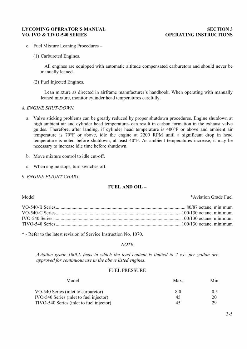
c. Fuel Mixture Leaning Procedures �
(1) Carbureted Engines.
All engines are equipped with automatic altitude compensated carburetors and should never bemanually leaned.
(2) Fuel Injected Engines.
Lean mixture as directed in airframe manufacturer�s handbook. When operating with manuallyleaned mixture, monitor cylinder head temperatures carefully.
8. ENGINE SHUT-DOWN.
a. Valve sticking problems can be greatly reduced by proper shutdown procedures. Engine shutdown athigh ambient air and cylinder head temperatures can result in carbon formation in the exhaust valveguides. Therefore, after landing, if cylinder head temperature is 400°F or above and ambient airtemperature is 70°F or above, idle the engine at 2200 RPM until a significant drop in headtemperature is noted before shutdown, at least 40°F. As ambient temperatures increase, it may benecessary to increase idle time before shutdown.
b. Move mixture control to idle cut-off.
c. When engine stops, turn switches off.
9. ENGINE FLIGHT CHART.
FUEL AND OIL �
Model *Aviation Grade Fuel
VO-540-B Series........................................................................................................... 80/87 octane, minimumVO-540-C Series....................................................................................................... 100/130 octane, minimumIVO-540 Series ......................................................................................................... 100/130 octane, minimumTIVO-540 Series....................................................................................................... 100/130 octane, minimum
* - Refer to the latest revision of Service Instruction No. 1070.
NOTE
Aviation grade 100LL fuels in which the lead content is limited to 2 c.c. per gallon areapproved for continuous use in the above listed engines.
FUEL PRESSURE
Model Max. Min.
VO-540 Series (inlet to carburetor) 8.0 0.5IVO-540 Series (inlet to fuel injector) 45 20TIVO-540 Series (inlet to fuel injector) 45 29
3-5
SECTION 3 LYCOMING OPERATOR�S MANUAL OPERATING INSTRUCTIONS VO, IVO & TIVO-540 SERIES
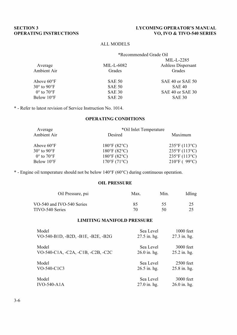
ALL MODELS
*Recommended Grade Oil
AverageAmbient Air
MIL-L-6082Grades
MIL-L-2285Ashless Dispersant
Grades
Above 60°F30° to 90°F
0° to 70°FBelow 10°F
SAE 50SAE 50SAE 30SAE 20
SAE 40 or SAE 50SAE 40
SAE 40 or SAE 30SAE 30
* - Refer to latest revision of Service Instruction No. 1014.
OPERATING CONDITIONS
Average *Oil Inlet TemperatureAmbient Air Desired Maximum
Above 60°F30° to 90°F
0° to 70°FBelow 10°F
180°F (82°C)180°F (82°C)180°F (82°C)170°F (71°C)
235°F (113°C)235°F (113°C)235°F (113°C)210°F ( 99°C)
* - Engine oil temperature should not be below 140°F (60°C) during continuous operation.
OIL PRESSURE
Oil Pressure, psi Max. Min. Idling
VO-540 and IVO-540 Series 85 55 25TIVO-540 Series 70 50 25
LIMITING MANIFOLD PRESSURE
Model Sea Level 1000 feetVO-540-B1D, -B2D, -B1E, -B2E, -B2G 27.5 in. hg. 27.3 in. hg.
Model Sea Level 3000 feetVO-540-C1A, -C2A, -C1B, -C2B, -C2C 26.0 in. hg. 25.2 in. hg.
Model Sea Level 2500 feetVO-540-C1C3 26.5 in. hg. 25.8 in. hg.
Model Sea Level 3000 feetIVO-540-A1A 27.0 in. hg. 26.0 in. hg.
3-6
LYCOMING OPERATOR�S MANUAL SECTION 3 VO, IVO & TIVO-540 SERIES OPERATING INSTRUCTIONS
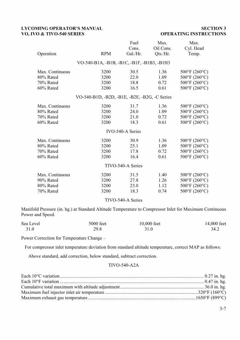
Operation RPM
FuelCons.
Gal./Hr.
Max.Oil Cons.Qts./Hr.
Max.Cyl. Head
Temp.
VO-540-B1A, -B1B, -B1C, -B1F, -B1B3, -B1H3
Max. Continuous 3200 30.5 1.36 500°F (260°C)80% Rated 3200 22.0 1.09 500°F (260°C)70% Rated 3200 18.8 0.72 500°F (260°C)60% Rated 3200 16.5 0.61 500°F (260°C)
VO-540-B1D, -B2D, -B1E, -B2E, -B2G, -C Series
Max. Continuous 3200 31.7 1.36 500°F (260°C)80% Rated 3200 24.0 1.09 500°F (260°C)70% Rated 3200 21.0 0.72 500°F (260°C)60% Rated 3200 18.3 0.61 500°F (260°C)
IVO-540-A Series
Max. Continuous 3200 30.9 1.36 500°F (260°C)80% Rated 3200 25.1 1.09 500°F (260°C)70% Rated 3200 17.8 0.72 500°F (260°C)60% Rated 3200 16.4 0.61 500°F (260°C)
TIVO-540-A Series
Max. Continuous 3200 31.5 1.40 500°F (260°C)90% Rated 3200 27.8 1.26 500°F (260°C)80% Rated 3200 23.0 1.12 500°F (260°C)70% Rated 3200 18.3 0.74 500°F (260°C)
TIVO-540-A Series
Manifold Pressure (in. hg.) at Standard Altitude Temperature to Compressor Inlet for Maximum ContinuousPower and Speed.
Sea Level 5000 feet 10,000 feet 14,000 feet31.0 29.8 31.0 34.2
Power Correction for Temperature Change �
For compressor inlet temperature deviation from standard altitude temperature, correct MAP as follows:
Above standard, add correction, below standard, subtract correction.
TIVO-540-A2A
Each 10°C variation .......................................................................................................................... 0.27 in. hg.Each 10°F variation .......................................................................................................................... 0.47 in. hg.Cumulative total maximum with altitude adjustment....................................................................... 36.0 in. hg.Maximum fuel injector inlet air temperature ...............................................................................320°F (160°C)Maximum exhaust gas temperature ...........................................................................................1650°F (899°C)
3-7
SECTION 3 LYCOMING OPERATOR�S MANUAL OPERATING INSTRUCTIONS VO, IVO & TIVO-540 SERIES
Figure 3-1. Fuel Consumption � VO-540-B1A, -B1B, -B1C, -B1F, -B1B3, -B1H3
3-8
LYCOMING OPERATOR�S MANUAL SECTION 3 VO, IVO & TIVO-540 SERIES OPERATING INSTRUCTIONS
Figure 3-2. Sea Level and Altitude Performance � VO-540-B1A, -B1B, -B1C, -B1F, -B1B3, -B1H3
3-9
SECTION 3 LYCOMING OPERATOR�S MANUAL OPERATING INSTRUCTIONS VO, IVO & TIVO-540 SERIES
Figure 3-3. Fuel Consumption � VO-540-B1D, -B2D, -B1E, -B2E, -B2G
3-10
LYCOMING OPERATOR�S MANUAL SECTION 3 VO, IVO & TIVO-540 SERIES OPERATING INSTRUCTIONS
Figure 3-4. Sea Level and Altitude Performance � VO-40-B1D, -B2D, -B1E, -B2E, -B1G
3-11
SECTION 3 LYCOMING OPERATOR�S MANUAL OPERATING INSTRUCTIONS VO, IVO & TIVO-540 SERIES
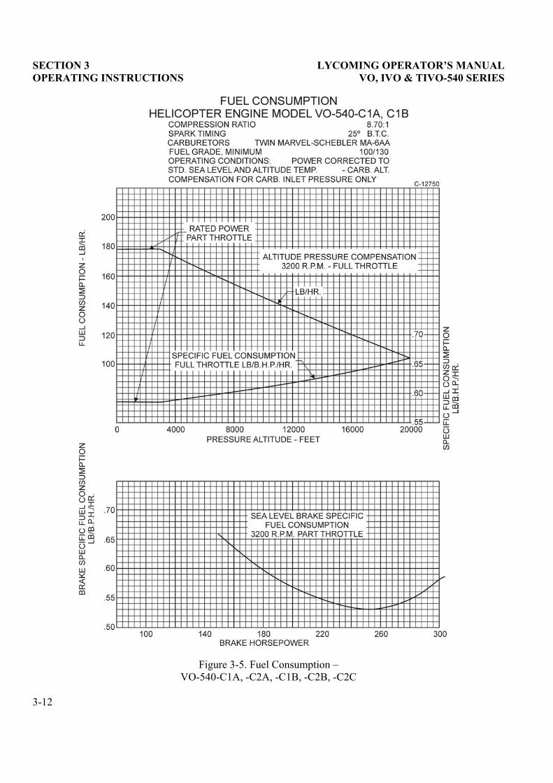
Figure 3-5. Fuel Consumption � VO-540-C1A, -C2A, -C1B, -C2B, -C2C
3-12
LYCOMING OPERATOR�S MANUAL SECTION 3 VO, IVO & TIVO-540 SERIES OPERATING INSTRUCTIONS
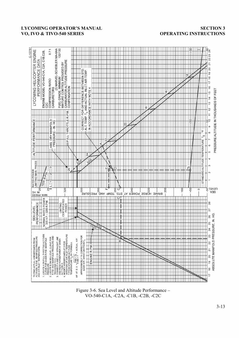
Figure 3-6. Sea Level and Altitude Performance � VO-540-C1A, -C2A, -C1B, -C2B, -C2C
3-13
SECTION 3 LYCOMING OPERATOR�S MANUAL OPERATING INSTRUCTIONS VO, IVO & TIVO-540 SERIES
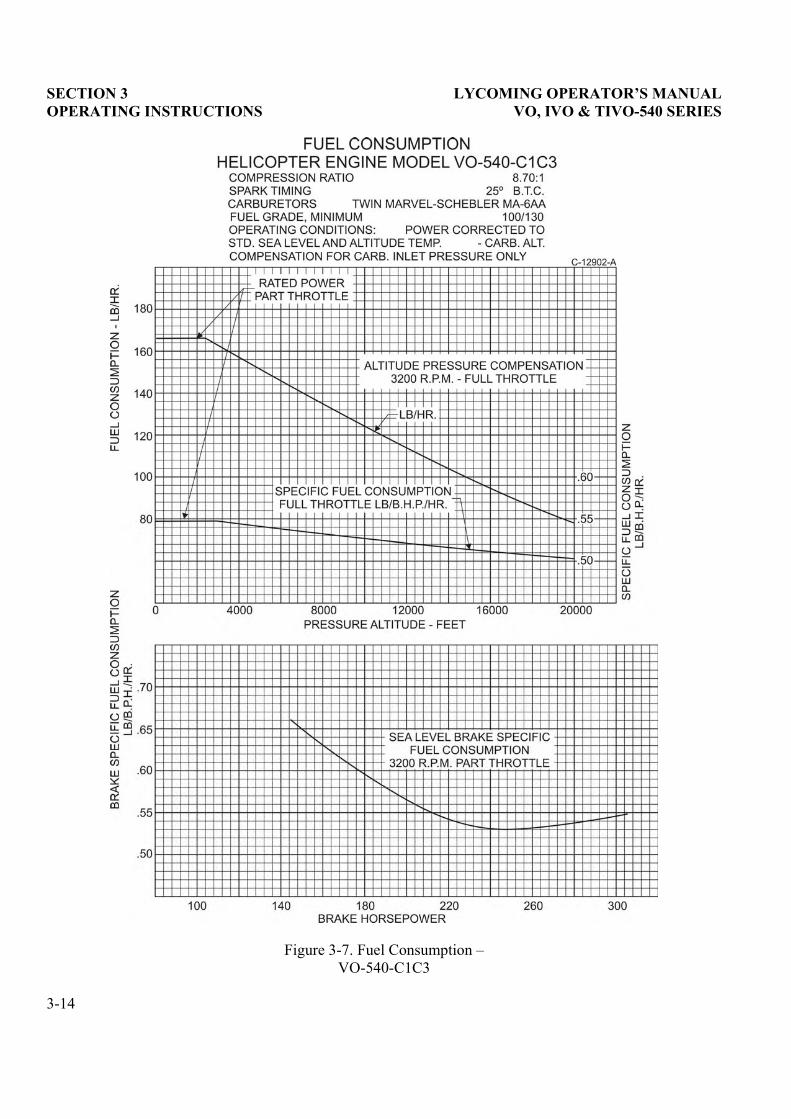
Figure 3-7. Fuel Consumption � VO-540-C1C3
3-14
LYCOMING OPERATOR’S MANUAL SECTION 3
VO, IVO & TIVO-540 SERIES OPERATING INSTRUCTIONS
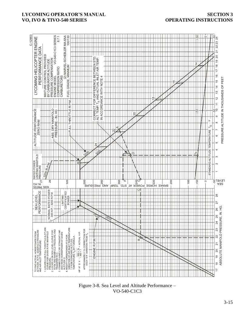
Figure 3-8. Sea Level and Altitude Performance –
VO-540-C1C3
3-15
SECTION 3 LYCOMING OPERATOR�S MANUAL OPERATING INSTRUCTIONS VO, IVO & TIVO-540 SERIES
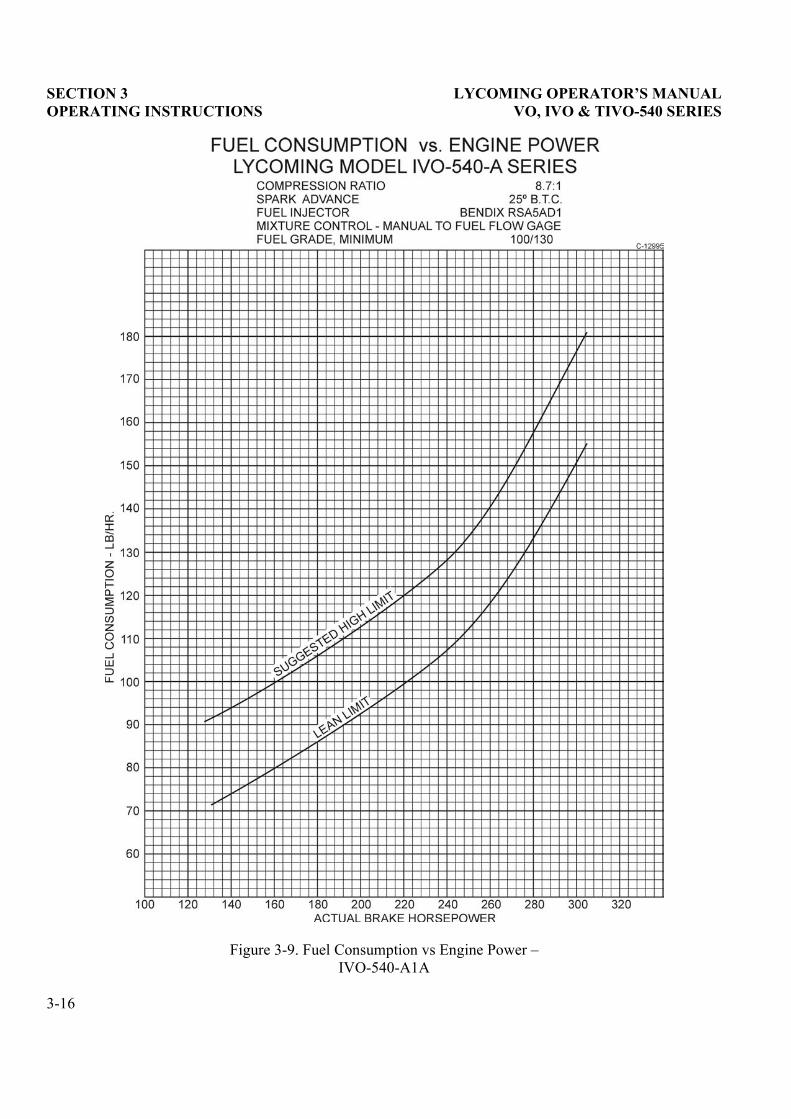
Figure 3-9. Fuel Consumption vs Engine Power � IVO-540-A1A
3-16
LYCOMING OPERATOR�S MANUAL SECTION 3 VO, IVO & TIVO-540 SERIES OPERATING INSTRUCTIONS
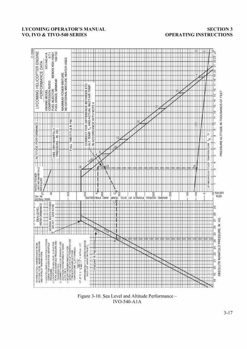
Figure 3-10. Sea Level and Altitude Performance � IVO-540-A1A
3-17
SECTION 3 LYCOMING OPERATOR�S MANUAL OPERATING INSTRUCTIONS VO, IVO & TIVO-540 SERIES
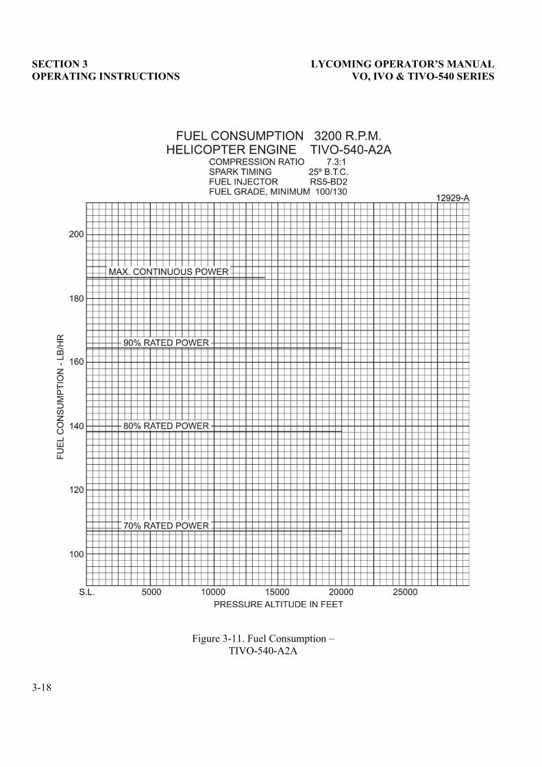
Figure 3-11. Fuel Consumption � TIVO-540-A2A
3-18
LYCOMING OPERATOR�S MANUAL SECTION 3 VO, IVO & TIVO-540 SERIES OPERATING INSTRUCTIONS
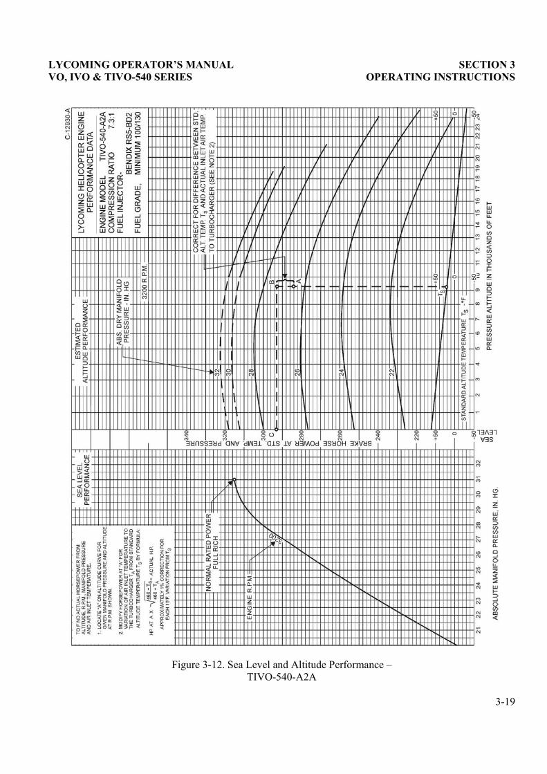
Figure 3-12. Sea Level and Altitude Performance � TIVO-540-A2A
3-19

This Page Intentionally Left Blank.
LYCOMING OPERATOR�S MANUAL
SECTION 4PERIODIC INSPECTIONS
Page
General.......................................................................................................................................................... 4-1
Daily Pre-Flight Inspection
Engine......................................................................................................................................................... 4-2
Turbocharger ............................................................................................................................................ 4-2
25-Hour Inspection
Engine......................................................................................................................................................... 4-2
50-Hour Inspection
Engine......................................................................................................................................................... 4-2
Turbocharger ............................................................................................................................................ 4-4
100-Hour Inspection
Engine......................................................................................................................................................... 4-4
Turbocharger ............................................................................................................................................ 4-4
400-Hour Inspection
Engine......................................................................................................................................................... 4-5
Non-Scheduled Inspection........................................................................................................................... 4-5

This Page Intentionally Left Blank.
LYCOMING OPERATOR�S MANUAL SECTION 4 VO, IVO & TIVO-540 SERIES PERIODIC INSPECTIONS
SECTION 4
PERIODIC INSPECTIONS
NOTE
Perhaps no other factor is quite so important to safety and durability of the aircraft and itscomponents as faithful and diligent attention to regular checks for minor troubles andprompt repair when they are found.
The operator should bear in mind that the items listed in the following pages do notconstitute a complete aircraft inspection, but are meant for the engine only. Consult theairframe manufacturer�s handbook for additional instructions.
Pre-Starting Inspection � The daily pre-flight inspection is a check of the aircraft prior to the first flight ofthe day. This inspection is to determine the general condition of the aircraft and engine.
The importance of proper pre-flight inspection cannot be over emphasized. Statistics prove severalhundred accidents occur yearly directly responsible to poor pre-flight.
Among the major causes of poor pre-flight inspection are lack of concentration, reluctance toacknowledge the need for a check list, and carelessness bred by familiarity and haste.
4-1
SECTION 4 LYCOMING OPERATOR�S MANUAL PERIODIC INSPECTIONS VO, IVO & TIVO-540 SERIES
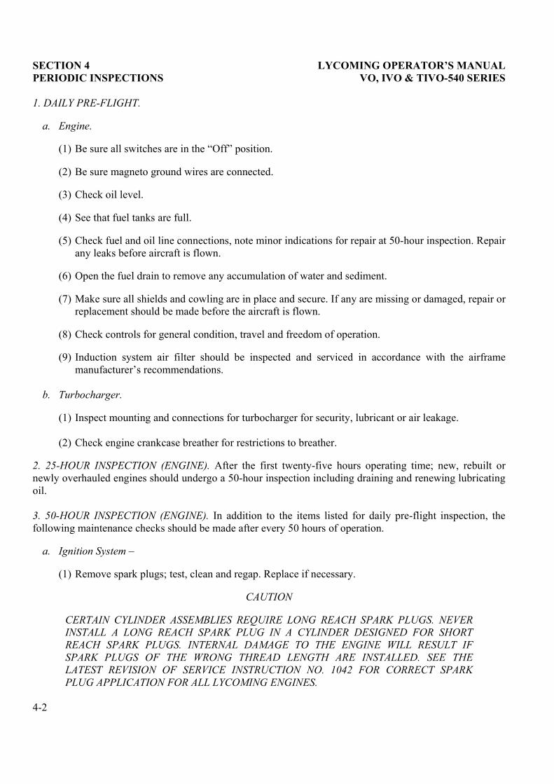
1. DAILY PRE-FLIGHT.
a. Engine.
(1) Be sure all switches are in the �Off� position.
(2) Be sure magneto ground wires are connected.
(3) Check oil level.
(4) See that fuel tanks are full.
(5) Check fuel and oil line connections, note minor indications for repair at 50-hour inspection. Repairany leaks before aircraft is flown.
(6) Open the fuel drain to remove any accumulation of water and sediment.
(7) Make sure all shields and cowling are in place and secure. If any are missing or damaged, repair orreplacement should be made before the aircraft is flown.
(8) Check controls for general condition, travel and freedom of operation.
(9) Induction system air filter should be inspected and serviced in accordance with the airframemanufacturer�s recommendations.
b. Turbocharger.
(1) Inspect mounting and connections for turbocharger for security, lubricant or air leakage.
(2) Check engine crankcase breather for restrictions to breather.
2. 25-HOUR INSPECTION (ENGINE). After the first twenty-five hours operating time; new, rebuilt ornewly overhauled engines should undergo a 50-hour inspection including draining and renewing lubricatingoil.
3. 50-HOUR INSPECTION (ENGINE). In addition to the items listed for daily pre-flight inspection, thefollowing maintenance checks should be made after every 50 hours of operation.
a. Ignition System �
(1) Remove spark plugs; test, clean and regap. Replace if necessary.
CAUTION
CERTAIN CYLINDER ASSEMBLIES REQUIRE LONG REACH SPARK PLUGS. NEVERINSTALL A LONG REACH SPARK PLUG IN A CYLINDER DESIGNED FOR SHORTREACH SPARK PLUGS. INTERNAL DAMAGE TO THE ENGINE WILL RESULT IFSPARK PLUGS OF THE WRONG THREAD LENGTH ARE INSTALLED. SEE THELATEST REVISION OF SERVICE INSTRUCTION NO. 1042 FOR CORRECT SPARKPLUG APPLICATION FOR ALL LYCOMING ENGINES.
4-2

LYCOMING OPERATOR�S MANUAL SECTION 4 VO, IVO & TIVO-540 SERIES PERIODIC INSPECTIONS
(2) Examine spark plug leads of cable and ceramics for corrosion and deposits. This condition isevidence of leaking spark plugs or improper cleaning of the spark plug walls or connector ends.Where this condition is found, clean the cable ends, spark plug walls and ceramics with a dry,clean cloth or a clean cloth moistened with methyl-ethyl ketone. All parts should be clean and drybefore reassembly.
(3) Check ignition harness for security of mounting clamps and be sure connections are tight at sparkplug and magneto terminals.
b. Fuel and Induction System �
(1) Check primer lines for leaks and security of clamps. Drain carburetor and clean carburetor fuelstrainer. Check mixture control and throttle linkage for travel, freedom of movement, security ofclamps and lubricate if necessary.
(2) Check carburetor air intake ducts for leaks, security, filter damage; evidence of dust or other solidmaterial in the ducts is indicative of inadequate filter care or damaged filter. Check vent lines forevidence of fuel or oil seepage; if present, fuel pump may require replacement.
c. Lubrication System �
(1) Check oil lines for leaks, particularly at connections; for security of anchorage and for wear due torubbing or vibration, for dents and cracks.
(2) Drain and refill external oil tanks of less than 15 quart capacity. Consult the latest revision ofService Instruction No. 1014 for recommended lubricating oil. Seasonal grades are listed inSection 5, 3. a. of this manual.
(3) Remove oil filter and clean thoroughly as described in Section 5, 3. c. of this manual. Notecarefully for presence of metal particles that are indicative of internal engine damage.
(4) If the engine is equipped with external oil filters, service in accordance with filter manufacturer�s instructions.
d. Exhaust System � Check attaching flanges at exhaust ports on cylinders for evidence of leakage. Ifthey are loose, they must be removed and machined flat before they are reassembled and tightened.Examine exhaust manifolds for general condition.
e. Cooling System �
(1) Check cowling and cylinder baffles for damage and secure anchorage. Any damaged or missingpart of the cooling system must be repaired or replaced before the aircraft resumes operation.
(2) Check cooling fan for nicks or cracks in blades.
f. Cylinders �
(1) Check rocker box covers for evidence of oil leaks. If found, replace gasket and tighten screws tospecified torque (50 in.-lbs.).
4-3

SECTION 4 LYCOMING OPERATOR�S MANUAL PERIODIC INSPECTIONS VO, IVO & TIVO-540 SERIES
(2) Check cylinders for evidence of excessive heat which is indicated by burned paint on the cylinder.This condition is indicative of internal damage to the cylinder and, if found, its cause must bedetermined and corrected before the aircraft resumes operation.
4. 50-HOUR INSPECTION (TURBOCHARGER).
a. All fluid lines and mounting brackets incorporated in the turbocharger system should be checked forleak tightness and any damage that could cause a restriction.
b. Check for accumulation of dirt or other interference with the linkage which might impair operation ofturbocharger. Clean or correct cause of interference.
c. The vent line from the actuator should be checked for oil leakage. Any constant oil leakage is causefor replacement of piston seal.
5. 100-HOUR INSPECTION (ENGINE). In addition to the items listed for daily pre-flight and 50-hourinspection, the following maintenance checks should be made after every one hundred hours of operation.
a. Electrical System � Check all wiring connected to the engine or accessories. Any shielded cables thatare damaged should be replaced. Replace clamps on loose wires and check terminals for security andcleanliness.
b. Magnetos � Check condition of breaker points. Check for excessive oil in the breaker compartment, iffound, wipe dry with a clean lintless cloth. The felt located at the breaker points should be lubricatedin accordance with the magneto manufacturer�s instructions. Check magneto timing. Timingprocedure is described in Section 5. 1. b. of this manual.
c. Engine Accessories � Engine mounted accessories such as pumps, temperature and pressure sensingunits should be checked for secure mounting, tight connections and terminals.
d. Cylinders � Check cylinders visually for cracked or broken fins.
e. Engine Mounts � Check engine mounting bolts and bushings for security and excessive wear. Replaceany bushings that are excessively worn.
f. Primer Nozzles � Disconnect primer nozzles from engine and check for equal fuel flow.
g. Fuel Injection Nozzles and Fuel Lines � Check for dye stains at connections (indicating leakage), andsecurity of lines and nozzles.
h. Lubrication System � Drain and refill external oil tanks of more than 15 quart capacity.
6. 100-HOUR INSPECTION (TURBOCHARGER).
a. Inspect all air ducting and connections in system for leaks. Make inspection with engine shut downand operating. Check at manifold connections to turbine inlet and at engine exhaust manifolds.
4-4
LYCOMING OPERATOR�S MANUAL SECTION 4 VO, IVO & TIVO-540 SERIES PERIODIC INSPECTIONS
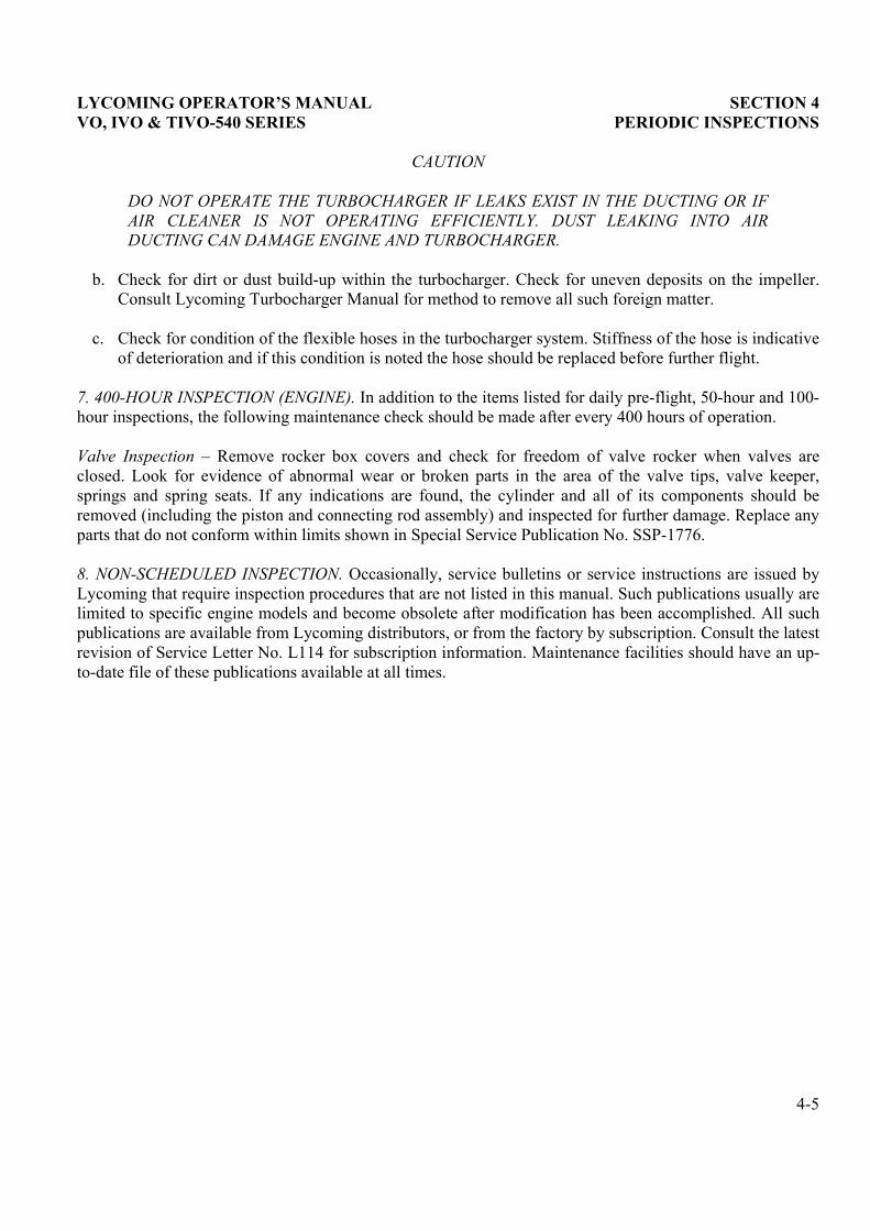
CAUTION
DO NOT OPERATE THE TURBOCHARGER IF LEAKS EXIST IN THE DUCTING OR IFAIR CLEANER IS NOT OPERATING EFFICIENTLY. DUST LEAKING INTO AIRDUCTING CAN DAMAGE ENGINE AND TURBOCHARGER.
b. Check for dirt or dust build-up within the turbocharger. Check for uneven deposits on the impeller.Consult Lycoming Turbocharger Manual for method to remove all such foreign matter.
c. Check for condition of the flexible hoses in the turbocharger system. Stiffness of the hose is indicativeof deterioration and if this condition is noted the hose should be replaced before further flight.
7. 400-HOUR INSPECTION (ENGINE). In addition to the items listed for daily pre-flight, 50-hour and 100-hour inspections, the following maintenance check should be made after every 400 hours of operation.
Valve Inspection � Remove rocker box covers and check for freedom of valve rocker when valves areclosed. Look for evidence of abnormal wear or broken parts in the area of the valve tips, valve keeper,springs and spring seats. If any indications are found, the cylinder and all of its components should beremoved (including the piston and connecting rod assembly) and inspected for further damage. Replace anyparts that do not conform within limits shown in Special Service Publication No. SSP-1776.
8. NON-SCHEDULED INSPECTION. Occasionally, service bulletins or service instructions are issued byLycoming that require inspection procedures that are not listed in this manual. Such publications usually arelimited to specific engine models and become obsolete after modification has been accomplished. All suchpublications are available from Lycoming distributors, or from the factory by subscription. Consult the latestrevision of Service Letter No. L114 for subscription information. Maintenance facilities should have an up-to-date file of these publications available at all times.
4-5

This Page Intentionally Left Blank.
LYCOMING OPERATOR�S MANUAL
SECTION 5MAINTENANCE PROCEDURES
Page
General.......................................................................................................................................................... 5-1
Ignition System
Ignition Harness and Wire Replacement................................................................................................ 5-1
Timing Magneto to Engine....................................................................................................................... 5-1
Generator or Alternator Output ............................................................................................................. 5-2
Fuel System
Repair of Fuel Leaks................................................................................................................................. 5-2
Carburetor Inlet Screen Assembly.......................................................................................................... 5-3
Fuel Grades and Limitations ................................................................................................................... 5-3
Air Intake Ducts and Filters .................................................................................................................... 5-3
Idle Speed and Mixture Adjustment ....................................................................................................... 5-3
Lubrication System
Oil Grades and Limitations...................................................................................................................... 5-4
Pre-Oiling Procedure................................................................................................................................ 5-4
Oil Filter..................................................................................................................................................... 5-4
Oil Pressure Relief Valve.......................................................................................................................... 5-5
Cylinders....................................................................................................................................................... 5-5
Turbocharger Control System
Exhaust Bypass Valve............................................................................................................................... 5-8
Density Controller..................................................................................................................................... 5-8

This Page Intentionally Left Blank.
LYCOMING OPERATOR�S MANUAL SECTION 5 VO, IVO & TIVO-540 SERIES MAINTENANCE PROCEDURES
SECTION 5
MAINTENANCE PROCEDURES
The procedure described in this section are provided to guide and instruct personnel in performing suchmaintenance operations that may be required in conjunction with the periodic inspections listed in precedingsection.
1. IGNITION SYSTEM.
a. Ignition Harness and Wire Replacement � In the event that an ignition harness or an individual lead isto be replaced, consult the wiring diagram to be sure harness is correctly installed. Mark location ofclamps and clips to be certain the replacement is fastened at the correct location.
b. Timing Magnetos to Engine � Although several combinations of magnetos are used on the subjectengines (see Table of Models for model application), the timing procedures in the followingparagraphs are the same for all magnetos. Either the impulse coupling or retard breaker magneto(whichever is applicable) is installed on the right side of the engine.
(1) Remove the timing inspection hole plug, located on the left side of the accessory housing adjacentto the magneto. Remove a spark plug from No. 1 cylinder and place a thumb over the spark plughole. Rotate the crankshaft in direction of normal rotation until the compression stroke is reached,this is indicated by a positive pressure inside the cylinder tending to push thumb off spark plughole. Look into timing hole and continue turning crankshaft until timing pin and timing mark onthe chamfered tooth of camshaft gear are in alignment. At this point, engine is at 25° BTC oncompression stroke of No. 1 cylinder and is ready for assembly of the magnetos.
NOTE
If the crankshaft is accidentally turned in the direction opposite normal rotation, repeat theabove procedure as accumulated backlash will make the final timing incorrect.
(2) Remove the inspection plugs from both magnetos and turn the drive shafts in direction of normalrotation until the first painted chamfered tooth on the distributor gear is aligned in the center of theinspection window. Being sure that the gear does not move from this position, install gaskets andmagnetos on the engine. Secure with washers and nuts; tighten only finger tight.
NOTE
In order to turn the shaft on an impulse coupling magneto, depress the pawl on the impulsecoupling with the finger.
(3) Using a battery powered timing light, attach the positive lead to a suitable terminal connected tothe ground terminal of the magneto and the negative lead to any unpainted portion of the engine.Rotate the magneto in its mounting flange to a point where the light comes on, then slowly turn itin the opposite direction until the light goes out. Bring the magneto back slowly until the light justcomes on and tighten nuts. Repeat this with the second magneto.
5-1
SECTION 5 LYCOMING OPERATOR�S MANUAL MAINTENANCE PROCEDURES VO, IVO & TIVO-540 SERIES
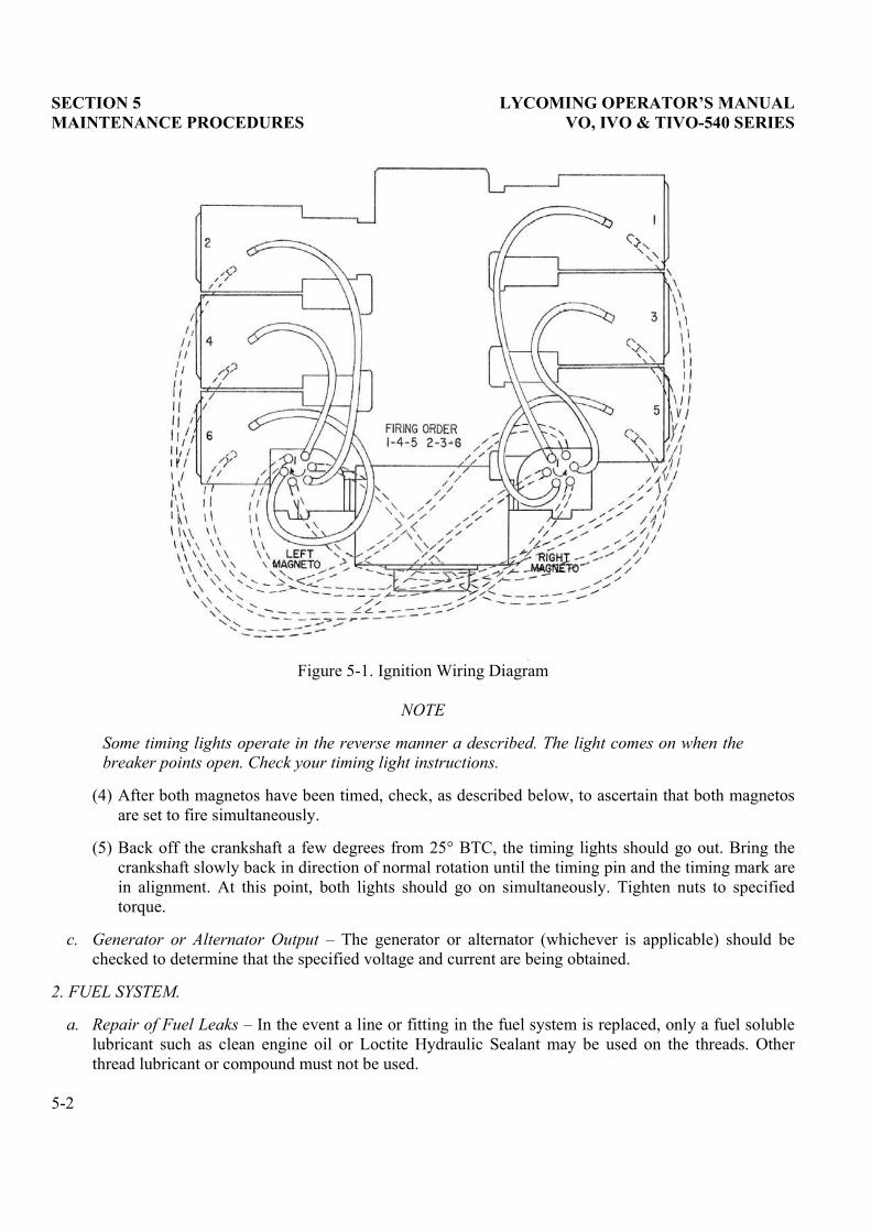
Figure 5-1. Ignition Wiring Diagram
NOTE
Some timing lights operate in the reverse manner a described. The light comes on when thebreaker points open. Check your timing light instructions.
(4) After both magnetos have been timed, check, as described below, to ascertain that both magnetosare set to fire simultaneously.
(5) Back off the crankshaft a few degrees from 25° BTC, the timing lights should go out. Bring thecrankshaft slowly back in direction of normal rotation until the timing pin and the timing mark arein alignment. At this point, both lights should go on simultaneously. Tighten nuts to specifiedtorque.
c. Generator or Alternator Output � The generator or alternator (whichever is applicable) should bechecked to determine that the specified voltage and current are being obtained.
2. FUEL SYSTEM.
a. Repair of Fuel Leaks � In the event a line or fitting in the fuel system is replaced, only a fuel solublelubricant such as clean engine oil or Loctite Hydraulic Sealant may be used on the threads. Otherthread lubricant or compound must not be used.
5-2
LYCOMING OPERATOR�S MANUAL SECTION 5 VO, IVO & TIVO-540 SERIES MAINTENANCE PROCEDURES
b. Carburetor Inlet Screen Assembly � To remove, straighten the bent tangs on the gasket and removethe assembly. Check the screen for distortion or openings in the strainer. Replace for either of theseconditions. Clean screen assembly in solvent and dry with compressed air. To install the screenassembly in the throttle body and tighten to 35-40 in.-lbs. torque. Make certain the notch in the gasketengages the projection on the throttle body. Bend two or more tabs of the gasket against acorresponding face of the inlet strainer assembly.
c. Fuel Grades and Limitations � The aviation grade fuel recommended for the subject engines is shownon page 3-5.
In the event that the specified fuel is not available at some locations, it is permissible to use higheroctane fuels. Fuel of a lower octane rating than specified is not to be used. Under no circumstancesshould automotive fuel be used (regardless of octane rating).
NOTE
It is recommended that personnel be familiar with the latest revision of Service InstructionNo. 1070 regarding specified fuel for Lycoming engines.
d. Air Intake Ducts and Filters � Check all air intake ducts for dirt and restrictions. Inspect and serviceair filters as instructed in the airframe manufacturer�s handbook.
e. Idle Speed and Mixture Adjustment �
(1) Warm up engine until oil and cylinder head temperatures are normal.
(2) Check magnetos. If the �mag-drop� is normal, proceed with the idle adjustment.
(3) Set throttle stop screw so that the engine idles at the airframe manufacturer�s recommended idling RPM. If the RPM changes appreciably after making idle mixture adjustment during thesucceeding steps, readjust the idle speed to the desired RPM
NOTE
The idle mixture must be adjusted with the boost pump on.
(4) When the idling speed has been stabilized, move the cockpit mixture control lever with a smooth,steady pull toward the �Idle Cut-Off� position and observe the tachometer for any change duringthe �leaning� process. Caution must be exercised to return the mixture control to the �Full Rich� position before the RPM can drop to a point where the engine cuts out. An increase of more than50 RPM while �leaning out� indicates an excessively rich idle mixture. An immediate decrease inRPM (if not preceded by a momentary increase) indicates the idle mixture is too lean.
If the above indicates that the idle adjustment is too rich or too lean, turn the idle mixtureadjustment in the direction required for correction, and check this new position by repeating theabove procedure. Make additional adjustments necessary until a check results in a momentarypick-up of approximately 50 RPM. Each time the adjustment is changed, the engine should be runup to a higher speed to clear the engine before proceeding with the RPM check. Make finaladjustment of the idle speed adjustment to obtain the desired idling RPM with closed throttle. Theabove method aims at a setting that will obtain maximum RPM with minimum manifold pressure.In case the setting does not remain stable, check the idle linkage; any looseness in this linkagewould cause erratic idling. In all cases, allowance should be made for the effect of weatherconditions and field altitude upon idling adjustment.
5-3
SECTION 5 LYCOMING OPERATOR�S MANUAL MAINTENANCE PROCEDURES VO, IVO & TIVO-540 SERIES
3. LUBRICATION SYSTEM.
a. Oil Grades and Limitations � Service the engines in accordance with the recommendations shown onpage 3-6.
It is recommended that the lubricating oil be changed as follows:
External tank � 10 to 15 quart capacity � Every 50 hours External tank � over 15 quart capacity � Every 100 hours
b. Pre-Oiling Procedure - Dry Sump Engines (Following installation or a prolonged period if idleness) -
(1) Fill the oil tank to proper level
(2) Disconnect the oil inlet connection at the oil pump and drain a sufficient amount of oil to eliminateany possible obstruction or air in the inlet passage.
(3) Reinstall oil inlet connection.
(4) Remove one spark plug from each cylinder.
(5) Put fuel and ignition switches in �off� position.
(6) Turn engine with starter until a minimum pressure of 20 lbs. is indicated on the gauge.
(7) Allow starter to cool and again engage starter for several ½ minute periods. Allow starter to coolafter each engagement.
NOTE
Lack of pressure build-up or rapid drop-off of pressure is an indication of air in the line. Toremedy this, repeat steps (2) and (3) and continue until pressure is indicated.
(8) Reinstall spark plugs.
NOTE
These steps are necessary in all dry sump engines to avert possible high speed bearingfailure during initial starts.
c. Oil Filter � Clean the engine oil filter as follows: Under normal conditions, washing the filterassembly with Varsol and compressed air will be sufficient. If the filter is heavily carboned, it may bedipped in a decarbonizing solution (usually heated). A great many decarbonizing agents are available,including such products as Gunk, Penetrol and many others. The loosened carbon can be washed awaywith Varsol and compressed air. The filter may also be cleaned by boiling in water and a commercialdetergent for a period of ten minutes, rinsed and dried with compressed air.
5-4
LYCOMING OPERATOR�S MANUAL SECTION 5 VO, IVO & TIVO-540 SERIES MAINTENANCE PROCEDURES
d. Oil Pressure Relief Valve � These engines are equipped with an adjustable oil pressure relief valveenabling oil pressure to be maintained within specified limits. If the pressure under normal operatingconditions should consistently be out of limits, adjust the valve as follows: With the enginethoroughly warmed up and running at a maximum of 2200 RPM, observe the reading on the oilpressure gauge. Stop the engine, remove the crown nut, loosen the locknut and turn the adjustingscrew in the direction required for correction. Screw in to increase pressure, out to decrease pressure.When the valve has been satisfactorily adjusted, tighten the locknut, install the crown nut andlockwire.
4. CYLINDERS. Although the complete procedure for disassembly and reassembly is given here, it isrecommended that, as a field operation, cylinder maintenance be confined to replacement of the entireassembly. Valve replacement should be undertaken only as an emergency measure.
a. Removal of Cylinder Assembly �
(1) Remove exhaust manifold.
(2) Remove rocker box drain tube, intake pipe, baffle and any clips that might interfere with theremoval of the cylinder.
(3) Disconnect ignition harness elbows from spark plugs and remove spark plugs.
(4) Remove rocker box cover and rotate crankshaft until piston is approximately at top center of thecompression stroke. This approximate position may be located by observing top of piston throughthe spark plug hole and also noting the valve action.
(5) Remove rocker shaft covers from cylinder head.
(6) Slide valve rocker shafts from cylinder head far enough so that the valve rockers and thrustwashers can be removed. Remove rotator cap from exhaust valve stem. The rocker shafts can beremoved when the cylinder is removed from the engine.
(7) Remove push rods by grasping ball end and pulling out of shroud tube. Turn shroud tube 90°either way, this releases detent from spring. Remove shroud tubes by first releasing them from theseal seat in the cylinder head and then withdrawing from the crankcase. Remove shroud tubesleeves and seals from outer end of shroud tube and seals from crankcase. Discard all seals. Placewashers, springs and sleeves in proper compartment of cleaning basket.
NOTE
Hydraulic tappets, push rods, rocker arms and valves must be assembled in the samelocation from which they were removed.
(8) Remove cylinder base hold down nuts and pull cylinder directly away from the crankcase. Becareful not to allow the piston to drop against the crankcase as the piston leaves the cylinder.
(9) Use the old cylinder base oil seal ring and criss-cross over the cylinder base studs and aroundconnecting rods to keep rod from striking crankcase.
5-5
SECTION 5 LYCOMING OPERATOR�S MANUAL MAINTENANCE PROCEDURES VO, IVO & TIVO-540 SERIES
NOTE
In the event that a spark plug heli-coil is to be replaced, it must be replaced with a .010oversize heli-coil.
b. Removal of Valves and Valve Springs from Cylinder � Place the cylinder over a block of wood to holdthe valves in a closed position. Compress the valve springs, using a valve spring compressor. Removethe split keys from the end of the valve stems. The valve springs and spring seats may now beremoved from the cylinder head. Hold the valve stems so that the valves will not fall out and removethe cylinder from the block. The valves can then be removed from the inside of the cylinder.
c. Removal of Piston from Connecting Rod � Remove the piston pin plugs and insert the piston pin pullerthrough the piston pin. Assemble the puller nut on the puller and proceed to remove the piston pin.
d. Removal of Hydraulic Tappet Plunger Assembly � It will be necessary to remove and bleed thehydraulic tappet plunger assembly so that the dry tappet clearance can be checked when the cylinderassembly is reinstalled. This is accomplished in the following manner:
(1) Remove the push rod socket by inserting the fore finger into the concave end of the socket andwithdrawing. The socket will usually stick to the finger firmly enough to be pulled out. If thesocket cannot be removed in this manner, it may be removed by grasping the edge of the socketwith a pair of needle nose pliers. However, care should be exercised to avoid scratching thesocket.
(2) To remove the hydraulic tappet plunger assembly, use the special Lycoming service tool. In theevent this tool is not available, the assembly may be removed by bending a hook in the end of apiece of wire. Insert the wire around the edge of the plunger assembly and turn the wire so that thehook engages the spring of the plunger assembly. Draw the assembly out of the tappet body bypulling gently.
CAUTION
NEVER USE A MAGNET TO REMOVE THE PLUNGER ASSEMBLY. MAGNETIZATIONOF THE ASSEMBLY MAY CAUSE THE BALL TO BECOME PERMANENTLY UNSEATED,CAUSING THE UNIT TO BE INOPERATIVE.
e. Assembly of Hydraulic Tappet Plunger Assembly � To assemble the unit, unseat the ball by inserting athin, clean bronze wire through the oil inlet hole. With the ball off its seat, insert the plunger and twistclockwise so that the spring catches.
f. Assembly of Valves in Cylinder � Prelubricate valve stems with Molytex Grease O or equivalent andinsert each valve in its respective guide.
(1) Place cylinder over a wood block so that the valves are held against the valve seats and assemblethe lower spring seat, auxiliary valve spring, and outer valve spring over the valve stem and guide.Place the upper spring seat on top of the springs.
NOTE
Place dampener end of the spring (close wound coils marked with dye or lacquer) toward thecylinder.
5-6
LYCOMING OPERATOR�S MANUAL SECTION 5 VO, IVO & TIVO-540 SERIES MAINTENANCE PROCEDURES
(2) Using a valve spring compressor, compress the valve springs and assemble the valve keys in thegroove around the upper end of the valve stem. Slowly release the pressure of the valve springcompressor and allow the upper spring seat to lock itself in place around the valve keys.
g. Assembly of Cylinder and Related Parts � Rotate crankshaft so that the connecting rod of the cylinderbeing assembled is at top center position with both tappets on the low side of the cam in a positionthat corresponds with both valves closed.
(1) Assemble piston with rings so that the cylinder number stamped on the piston pin boss is towardthe top of the engine. The piston pin should be a hand push fit. During assembly always use agenerous quantity of oil, both in the piston pin hole and on the piston pin.
(2) Assemble a piston pin plug at each end of the piston pin and place a new oil seal ring around thecylinder skirt. Coat piston and rings and the inside of the cylinder barrel generously with oil.
NOTE
Insert valve rocker shafts in cylinder head before assembling the cylinder.
(3) Using a piston ring compressor, assemble the cylinder over the piston so that the intake andexhaust ports are toward the rear of the engine. Push the cylinder all the way on, catching the ringcompressor as it is pushed off, and assemble the cylinder base hold down nuts. Before installingcylinder hold down nuts, lubricate crankcase thru-studs with any of the following lubricants orcombination of lubricants, 90% SAE 50W oil and 10% STP, Parker Thread Lube, 60% SAE 30Woil and 40% Parker Thread Lube.
NOTE
At any time a cylinder is replaced, it is necessary to retorque the thru-studs on the cylinderon the opposite side of the engine.
(a) Tighten the ½ inch cylinder base nuts to 300 in.-lbs. torque beginning with the upper left andproceeding clockwise.
(b) Tighten the ½ inch cylinder base nuts to 600 in.-lbs. in the exact sequence stated in (a).
(c) Tighten the inch cylinder base nuts to 300 in.-lbs., sequence is optional.
(d) During the final tightening procedure, bearing crush or crankshaft shift may have occurred,relieving the load on certain ½ inch nuts. Therefore, as a final check, repeat step (b) above todetermine if all ½ inch nuts are tightened to 600 in.-lbs. torque. Hold torque wrench on each ½inch nut for about five seconds. If the nut does not turn it may be presumed to be tightened tocorrect torque.
CAUTION
AFTER THE INSTALLATION OF THE CYLINDER IS COMPLETED, REMOVE ANYNICKS IN THE FINS BY BURRING OR FILING.
5-7
SECTION 5 LYCOMING OPERATOR�S MANUAL MAINTENANCE PROCEDURES VO, IVO & TIVO-540 SERIES
(4) Install each hydraulic tappet plunger assembly and socket in its respective position. Install springs,seals, sleeves and washers to each shroud tube and assemble in its respective position. Lockshroud tube in place by turning the tube ½ turn. This places the ears in the shroud tube in theindent position of the spring. Install the push rod in each shroud tube being certain the push rod isassembled in the same location from which it was removed.
(5) Assemble cap on end of exhaust valve stem and assemble each valve rocker in its respectiveposition by sliding the rocker shaft outward far enough to enable the rocker and thrust washer tobe placed between the bosses and then slide the rocker shaft in place to retain the assembly.Assemble the rocker shaft cover with gaskets. Tighten cover nuts to recommended torque (65 to85 in.-lbs.).
(6) Be sure that the piston is at top center of the compression stroke and that both valves are closed.Check clearance between the valve stem tip and the valve rocker. In order to check this clearance,place the thumb on the valve rocker directly over the push rod and push down so as to depress thehydraulic tappet plunger spring. While holding the spring depressed, the clearance should bebetween .028 and .080 inch. If clearance does not come within these limits, remove the push rodand install a longer or shorter push rod, as required to correct clearance.
NOTE
Inserting a longer push rod will decrease the clearance.
(7) Install intercylinder baffle, rocker box cover (tighten to 50 in.-lbs.), intake pipe, rocker box draintube and exhaust manifold.
5. TURBOCHARGER CONTROL SYSTEM (TIVO-540). The control system, consisting of the densitycontroller and the exhaust bypass valve (waste gate), automatically controls the output of the turbochargerover the broad engine altitude operating range. This control system prevents overboosting of the engine atlower altitudes and maintains the supply of air to the intake manifold to produce sea level power at altitude.Engine oil pressure supplies the fluid power to operate the control system. The supply pressure should be 60to 80 psig and have a flow capacity of 0.75 GPM.
a. Exhaust Bypass Valve (Waste Gate) � The waste gate is set to a predetermined setting as shown inFigure 5-2. This setting determines the critical altitude of the helicopter. The opening and closing ofthe valve during operation is controlled by oil pressure regulated by the density controller.
b. Density Controller � The density controller senses changes in compressor discharge air (deckpressure) and in turn regulates the bleed oil pressure which controls the action of the waste gate.
c. Density Controller Adjustment �
Take-off manifold pressure � 0.5 in. hg.
TIVO-540-A2A.......................................................................................................................... 31 in. hg.
For compressor inlet temperature deviation from standard altitude temperature, correct MAP asfollows: Above standard, add correction, below standard, subtract correction
5-8
LYCOMING OPERATOR�S MANUAL SECTION 5 VO, IVO & TIVO-540 SERIES MAINTENANCE PROCEDURES
Each 10°F variation................................................................................................................. 0.27 in. hg.Each 10°C variation ................................................................................................................ 0.47 in. hg.
The foregoing are flight conditions and the controls must be set as follows to obtain these settings.
(1) Install a 100 psi gauge to �Tee� at waste gate actuator.
(2) With the engine at 3200 RPM and collective set at low pitch, check inlet pressure setting. Thissetting should be within engine oil pressure limits.
(3) Increase engine power to a minimum 26 in. to 28 in. MAP for 5 to 10 minutes until the filter airand injector inlet air temperatures stabilize and recheck pressure. If tie down facilities are notavailable, operate the helicopter in stabilized flight.
(4) Check injector inlet air temperature and full throttle manifold pressure. Compare reading withcurve, Figure 5-3. Results must be within limits of curve. Example: With injector inlettemperature of 50°C (122°F), full throttle manifold pressure should be between 30.7 in. and 31.3in. hg. If it is found that the manifold pressure is not within limits, the density controller must bereset.
(5) To adjust the density controller breaker the lockwire and remove hex plug in end of controllerunit. Insert a screwdriver and turn counterclockwise to decrease and clockwise to increase the fullthrottle manifold pressure. The unit is very sensitive and must only be adjusted in smallincrements. 1/8 turn of the adjustment is equal to approximately 1 in. MAP.
NOTE
When adjusting the density controller a constant check must be made to the inlet gauge to seethat inlet pressure remains within specified limits.
d. Engine Ground Test Calibration for Density Controller � If conditions do not warrant using themethods described in the preceding paragraph, an approximate density control adjustment can bemade as follows:
(1) Install a 100 psi gauge to �Tee� at waste gate actuator inlet.
(2) Install a 100 psi gauge at actuator outlet.
(3) Start the engine and operate at 3200 RPM in flat pitch. The actuator pressure must fall within thelimits of the curve for the deck pressure developed by the turbine. For example, see Figure 5-4, ifthe deck pressure is 30 in. hg., and the supply pressure between 55 and 65, then the actuatorpressure must be between 24 and 28.5 psi on the outlet side of the actuator
(4) If the actuator pressure is not within limits the density controller must be adjusted as previouslydescribed.
NOTE
It must be remembered the above method is only an approximate setting.5-9

SECTION 5 LYCOMING OPERATOR�S MANUAL MAINTENANCE PROCEDURES VO, IVO & TIVO-540 SERIES
Figure 5-2. Exhaust Bypass Valve (Waste Gate) Open and Closed Settings
5-10
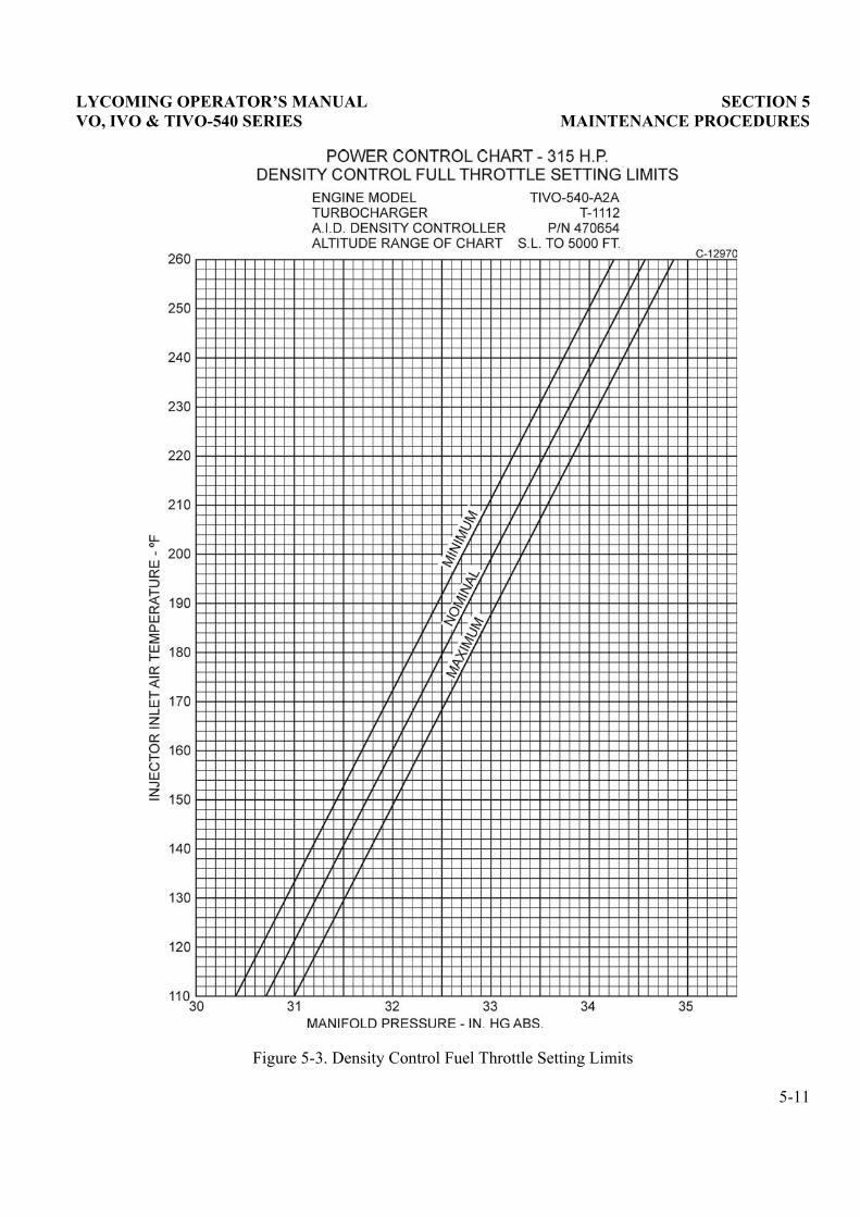
LYCOMING OPERATOR�S MANUAL SECTION 5 VO, IVO & TIVO-540 SERIES MAINTENANCE PROCEDURES
Figure 5-3. Density Control Fuel Throttle Setting Limits
5-11

SECTION 5 LYCOMING OPERATOR�S MANUAL MAINTENANCE PROCEDURES VO, IVO & TIVO-540 SERIES
Figure 5-4. Approximate Calibration Chart for Density Controller
5-12
LYCOMING OPERATOR�S MANUAL
SECTION 6TROUBLE-SHOOTING � ENGINE
Page
Failure of Engine to Start............................................................................................................................ 6-1
Failure of Engine to Idle Properly.............................................................................................................. 6-2
Failure of Engine to Develop Full Power................................................................................................... 6-2
Low Oil Pressure.......................................................................................................................................... 6-3
High Oil Temperature ................................................................................................................................. 6-3
Excessive Oil Consumption......................................................................................................................... 6-4
Cold Weather Difficulties............................................................................................................................ 6-4
Engine Does Not Stop .................................................................................................................................. 6-4
TROUBLE-SHOOTING � TURBOCHARGER
Engine Loses Power at Altitude.................................................................................................................. 6-5
Engine Surges ............................................................................................................................................... 6-5
High Deck Pressure...................................................................................................................................... 6-5
Low Deck Pressure ...................................................................................................................................... 6-6
Waste Gate Butterfly ................................................................................................................................... 6-6

This Page Intentionally Left Blank.

LYCOMING OPERATOR�S MANUAL SECTION 6 VO, IVO & TIVO-540 SERIES TROUBLE-SHOOTING
SECTION 6
TROUBLE-SHOOTING
Experience has proven that the best method of �trouble-shooting� is to decide on the various causes of a given trouble and then to eliminate causes one by one, beginning with the most probable. The followingcharts list some of the more common troubles, which may be encountered in maintaining engines andturbochargers, their probable causes and remedies.
1. TROUBLE-SHOOTING � ENGINE.
TROUBLE PROBABLE CAUSE REMEDY
Failure of Engine to Start Lack of fuel. Check fuel system for leaks. Fillfuel tank. Clean dirty lines,strainers or fuel valves.
Underpriming. Prime as directed in Section 3.
Overpriming. Leave ignition �off� and mixture control in �Idle Cut-Off�, open throttle and �unload� engine by cranking for a few seconds.
Incorrect throttle setting. Open throttle to one-fourth of itsrange.
Defective spark plugs. Clean and adjust or replace sparkplugs.
Defective ignition wire. Check with electric tester, andreplace any defective wires.
Defective battery. Replace with charged battery.
Improper operation of magnetobreaker.
Clean points. Check internaltiming of magnetos.
Lack of sufficient fuel flow. Disconnect fuel line at carburetoror fuel injector and check fuelflow.
Manual mixture control in �Idle-Cut-Off� (Carb.).
Check the linkage.
Water in carburetor or fuelinjector.
Drain carburetor or fuel injectorand fuel lines.
Internal failure. Check oil screens for metalparticles. If found, completeoverhaul of the engine may beindicated.
6-1
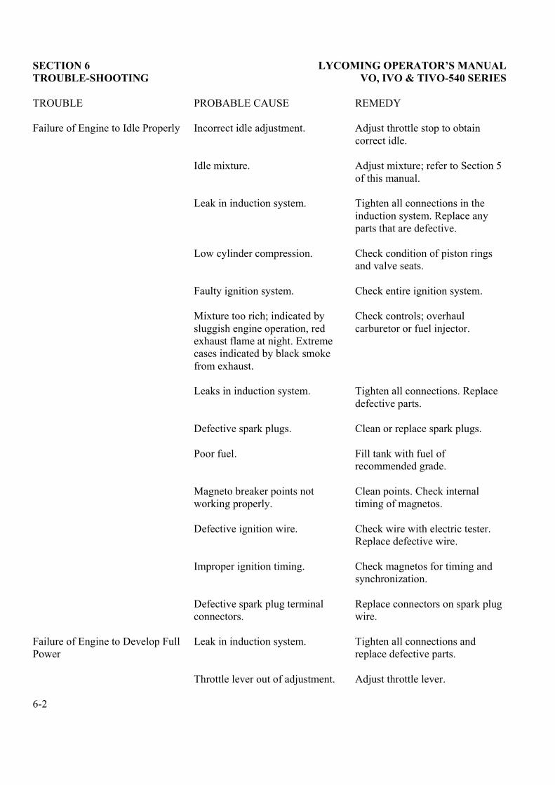
SECTION 6 LYCOMING OPERATOR�S MANUAL TROUBLE-SHOOTING VO, IVO & TIVO-540 SERIES
TROUBLE PROBABLE CAUSE REMEDY
Failure of Engine to Idle Properly Incorrect idle adjustment. Adjust throttle stop to obtaincorrect idle.
Idle mixture. Adjust mixture; refer to Section 5of this manual.
Leak in induction system. Tighten all connections in theinduction system. Replace anyparts that are defective.
Low cylinder compression. Check condition of piston ringsand valve seats.
Faulty ignition system. Check entire ignition system.
Mixture too rich; indicated bysluggish engine operation, redexhaust flame at night. Extremecases indicated by black smokefrom exhaust.
Check controls; overhaulcarburetor or fuel injector.
Leaks in induction system. Tighten all connections. Replacedefective parts.
Defective spark plugs. Clean or replace spark plugs.
Poor fuel. Fill tank with fuel ofrecommended grade.
Magneto breaker points notworking properly.
Clean points. Check internaltiming of magnetos.
Defective ignition wire. Check wire with electric tester.Replace defective wire.
Improper ignition timing. Check magnetos for timing andsynchronization.
Defective spark plug terminalconnectors.
Replace connectors on spark plugwire.
Failure of Engine to Develop FullPower
Leak in induction system. Tighten all connections andreplace defective parts.
Throttle lever out of adjustment. Adjust throttle lever.
6-2
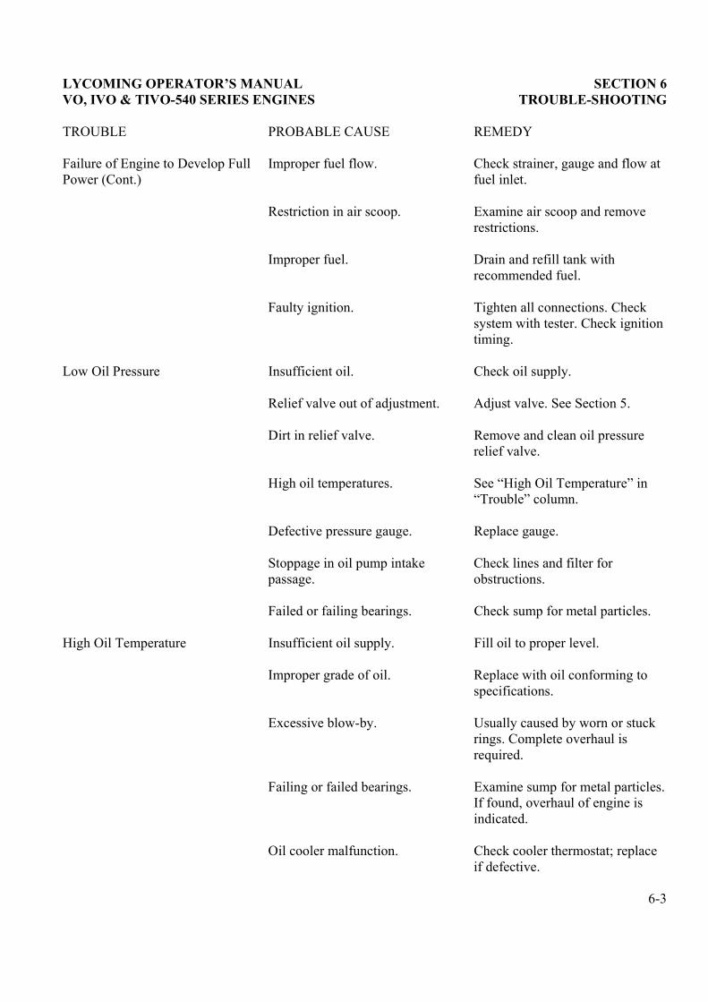
LYCOMING OPERATOR�S MANUAL SECTION 6 VO, IVO & TIVO-540 SERIES ENGINES TROUBLE-SHOOTING
TROUBLE PROBABLE CAUSE REMEDY
Failure of Engine to Develop FullPower (Cont.)
Improper fuel flow. Check strainer, gauge and flow atfuel inlet.
Restriction in air scoop. Examine air scoop and removerestrictions.
Improper fuel. Drain and refill tank withrecommended fuel.
Faulty ignition. Tighten all connections. Checksystem with tester. Check ignitiontiming.
Low Oil Pressure Insufficient oil. Check oil supply.
Relief valve out of adjustment. Adjust valve. See Section 5.
Dirt in relief valve. Remove and clean oil pressurerelief valve.
High oil temperatures. See �High Oil Temperature� in �Trouble� column.
Defective pressure gauge. Replace gauge.
Stoppage in oil pump intakepassage.
Check lines and filter forobstructions.
Failed or failing bearings. Check sump for metal particles.
High Oil Temperature Insufficient oil supply. Fill oil to proper level.
Improper grade of oil. Replace with oil conforming tospecifications.
Excessive blow-by. Usually caused by worn or stuckrings. Complete overhaul isrequired.
Failing or failed bearings. Examine sump for metal particles.If found, overhaul of engine isindicated.
Oil cooler malfunction. Check cooler thermostat; replaceif defective.
6-3
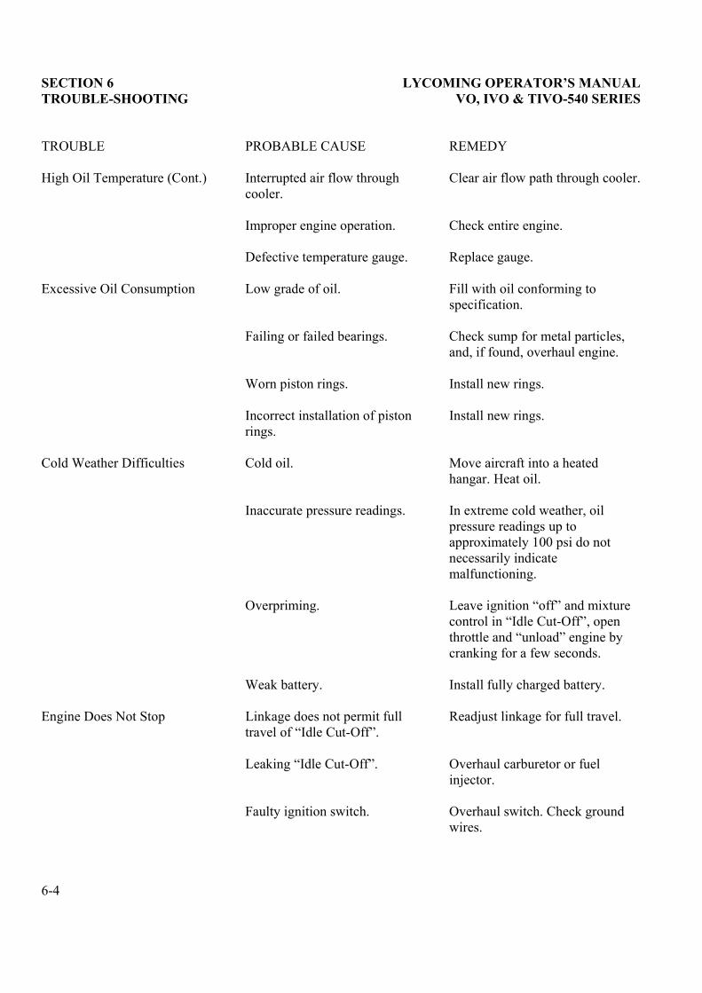
SECTION 6 LYCOMING OPERATOR�S MANUAL TROUBLE-SHOOTING VO, IVO & TIVO-540 SERIES
TROUBLE PROBABLE CAUSE REMEDY
High Oil Temperature (Cont.) Interrupted air flow throughcooler.
Clear air flow path through cooler.
Improper engine operation. Check entire engine.
Defective temperature gauge. Replace gauge.
Excessive Oil Consumption Low grade of oil. Fill with oil conforming tospecification.
Failing or failed bearings. Check sump for metal particles,and, if found, overhaul engine.
Worn piston rings. Install new rings.
Incorrect installation of pistonrings.
Install new rings.
Cold Weather Difficulties Cold oil. Move aircraft into a heatedhangar. Heat oil.
Inaccurate pressure readings. In extreme cold weather, oilpressure readings up toapproximately 100 psi do notnecessarily indicatemalfunctioning.
Overpriming. Leave ignition �off� and mixture control in �Idle Cut-Off�, open throttle and �unload� engine by cranking for a few seconds.
Weak battery. Install fully charged battery.
Engine Does Not Stop Linkage does not permit fulltravel of �Idle Cut-Off�.
Readjust linkage for full travel.
Leaking �Idle Cut-Off�. Overhaul carburetor or fuelinjector.
Faulty ignition switch. Overhaul switch. Check groundwires.
6-4
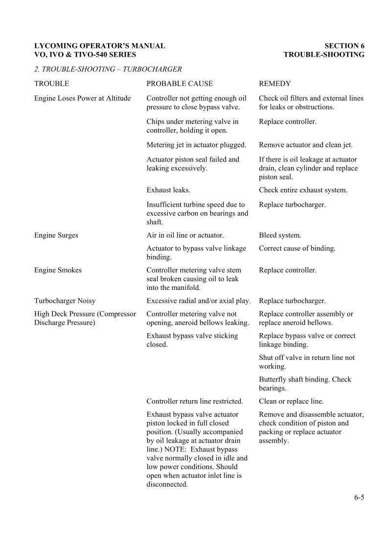
LYCOMING OPERATOR�S MANUAL SECTION 6 VO, IVO & TIVO-540 SERIES TROUBLE-SHOOTING
2. TROUBLE-SHOOTING � TURBOCHARGER
TROUBLE PROBABLE CAUSE REMEDY
Engine Loses Power at Altitude Controller not getting enough oilpressure to close bypass valve.
Check oil filters and external linesfor leaks or obstructions.
Chips under metering valve incontroller, holding it open.
Replace controller.
Metering jet in actuator plugged. Remove actuator and clean jet.
Actuator piston seal failed andleaking excessively.
If there is oil leakage at actuatordrain, clean cylinder and replacepiston seal.
Exhaust leaks. Check entire exhaust system.
Insufficient turbine speed due toexcessive carbon on bearings andshaft.
Replace turbocharger.
Engine Surges Air in oil line or actuator. Bleed system.
Actuator to bypass valve linkagebinding.
Correct cause of binding.
Engine Smokes Controller metering valve stemseal broken causing oil to leakinto the manifold.
Replace controller.
Turbocharger Noisy Excessive radial and/or axial play. Replace turbocharger.
High Deck Pressure (CompressorDischarge Pressure)
Controller metering valve notopening, aneroid bellows leaking.
Replace controller assembly orreplace aneroid bellows.
Exhaust bypass valve stickingclosed.
Replace bypass valve or correctlinkage binding.
Shut off valve in return line notworking.
Butterfly shaft binding. Checkbearings.
Controller return line restricted. Clean or replace line.
Exhaust bypass valve actuatorpiston locked in full closedposition. (Usually accompaniedby oil leakage at actuator drainline.) NOTE: Exhaust bypassvalve normally closed in idle andlow power conditions. Shouldopen when actuator inlet line isdisconnected.
Remove and disassemble actuator,check condition of piston andpacking or replace actuatorassembly.
6-5
SECTION 6 LYCOMING OPERATOR�S MANUAL TROUBLE-SHOOTING VO, IVO & TIVO-540 SERIES
TROUBLE PROBABLE CAUSE REMEDY
High Deck Pressure (CompressorDischarge Pressure) (Cont.)
Density controller malfunction. Replace controller.
Low Deck Pressure (CompressorDischarge Pressure)
Restriction in lines from actuatorto density controller, safety valveand reservoir.
Remove and clean lines.
Density controller is in need ofadjustment.
Adjust density controller to curve.
Inlet orifice to actuator clogged. Remove inlet line at actuator andclean orifice.
Density controller malfunction. Replace unit.
Exhaust bypass valve butterfly notclosing
1. Low pressure. Clogged orificein inlet to actuator.
2. Butterfly shaft binding. Checkbearings.
Turbocharger impeller binding,frozen or rubbing housing.
Check bearings. Replaceturbocharger.
Piston seal in actuator leaking.(Usually accompanied by oilleakage at drain line.)
Remove and replace actuator ordisassemble and replace packing.
Exhaust Bypass Valve ButterflyOpens when Engine is Shut Off
Exhaust bypass valve actuatorpiston locked in full openposition. (Usually accompaniedby oil leakage at actuator drainline.) NOTE: Exhaust bypassvalve normally closed in idle andlow power conditions. Shouldopen when actuator inlet line isdisconnected.
Remove and disassemble actuator,check condition and operation ofpiston and packing, or replaceactuator assembly.
6-6

LYCOMING OPERATOR�S MANUAL
SECTION 7INSTALLATION AND STORAGE
Page
Preparation for Installation
Engine......................................................................................................................................................... 7-1
Carburetors or Fuel Injectors.................................................................................................................. 7-1
Preparation for Storage
Preservation Run ...................................................................................................................................... 7-2
Fuel .......................................................................................................................................................... 7-2
Oil ............................................................................................................................................................ 7-2
Duration of Run ..................................................................................................................................... 7-2
Cylinders................................................................................................................................................... 7-2
Carburetors or Fuel Injectors.................................................................................................................. 7-3
Shipping Case ............................................................................................................................................ 7-3
Recommended Procedure for Re-Preservation......................................................................................... 7-3

This Page Intentionally Left Blank.

LYCOMING OPERATOR�S MANUAL SECTION 7 VO, IVO & TIVO-540 SERIES INSTALLATION AND STORAGE
SECTION 7
INSTALLATION AND STORAGE
1. PREPARATION OF ENGINE FOR INSTALLATION. Before installing an engine that has been preparedfor storage, remove all dehydrator plugs, bags of desiccant and preservative oil from the engine.Preservative oil can be removed by removing the bottom spark plugs and turning the crankshaft three orfour revolutions. The preservative oil will drain from the spark plug holes. Engine should be in a horizontalposition when this operation is performed. Draining will be facilitated if the engine is tilted from side to sideduring the above operation. Preservative oil that has accumulated in the sump can be drained by removingthe oil sump drain plug. Engines that have been stored in a cold place should be moved to an environment ofat least 70°F (21°C) for a period of 24 hours before preservative oil is drained from the cylinders. If this isnot possible, heat the cylinders with heat lamps before attempting to drain the engine.
Should any of the dehydrator plugs containing crystals of silica-gel or similar material, be broken duringtheir term of storage or upon their removal from the engine, that portion of the engine must be disassembledand thoroughly cleaned before using the engine. The oil strainer should be removed and cleaned in gasolineor some other hydrocarbon solvent. The fuel drain screen located in the fuel inlet of the carburetor shouldalso be removed and cleaned in a hydrocarbon solvent. The operator should note if any valves are sticking,and if they are, this condition can be eliminated by coating the valve stems generously with a mixture ofgasoline and lubricating oil.
After the oil sump has been drained, drain plug should be replaced, tightened and safety wired. Fill theexternal tank to proper level with lubricating oil. The crankshaft should again be turned several revolutionsto saturate the interior of the engine with clean oil. When installing plugs, make sure they are clean. If not,wash them in petroleum solvent. There will be a small amount of preservative oil remaining in the engine;however, this can cause no harm. After 25 hours of operation, the lubricating oil should be drained while theengine is hot. This will remove any residual preservative oil that may have been present.
CAUTION
DO NOT ROTATE THE CRANKSHAFT OF AN ENGINE CONTAINING PRESERVATIVEOIL BEFORE REMOVING THE SPARK PLUGS, BECAUSE IF THE CYLINDERSCONTAIN ANY APPRECIABLE AMOUNT OF THE MIXTURE, THE RESULTINGACTION, KNOWN AS HYDRAULICING WILL CAUSE DAMAGE TO THE ENGINE. ALSO,ANY CONTACT OF THE PRESERVATIVE OIL WITH PAINTED SURFACES SHOULD BEAVOIDED.
Inspection of Engine Mounting � If the helicopter is one from which an engine has been removed, make surethe engine mount is not bent or damaged by distortion or misalignment because if it is, abnormal stressescan be produced within the engine.
Attaching Engine to Mounts � See airframe manufacturer�s applicable publication for method of mountingengine.
Installation � Consult installation drawings for location of accessories, drives, oil and fuel line connections.
2. PREPARATION OF CARBURETORS AND FUEL INJECTORS FOR INSTALLATION.
Carburetor and fuel injectors that have been prepared for storage should undergo the following proceduresbefore being placed in service.
7-1
SECTION 7 LYCOMING OPERATOR�S MANUAL INSTALLATION AND STORAGE VO, IVO & TIVO-540 SERIES
Carburetor � Remove the fuel drain plug and drain preservative oil. Remove the fuel inlet strainer assemblyand clean in a hydrocarbon solvent. Reinstall the fuel drain plug and fuel inlet strainer assembly. Check allplugs before installing in airframe.
Fuel Injectors � Remove and clean the fuel inlet strainer assembly in a hydrocarbon solvent. Inject cleanfuel into the fuel inlet connection with the fuel outlets uncapped until clean fuel flows from the outlets. Donot exceed 15 psi inlet pressure. Reinstall fuel inlet strainer assembly and check all plugs before installing inairframe.
3. PREPARATION OF ENGINE FOR STORAGE. The following procedure is intended for application toinstalled engines which are being removed from the aircraft, and will provide protection from corrosion fora period of thirty or sixty days.
Preservative Run � Immediately prior to removal of the engine from the aircraft, the engine should be givena preservative run under the following conditions.
Fuel � Normal service fuel.
Oil � Drain regular oil and replace with preservative type lubricating oil (Socony�s �Avrex 901�, Esso�s �Rust Ban 626� or equivalent.
Duration of Run � Operate the engine for a period of four minutes, holding the engine speed to a maximumof 2200 RPM. All precautions pertaining to ground running should be carefully observed. Cylinder headtemperature should not be allowed to exceed 475°F, and magneto temperatures should not be allowed toexceed 180°F. Ignition harness temperatures should be held within the prescribed limits. At the completionof the preservative run, while the engine is warm, drain the preservative oil.
NOTE
Preservative oil drained from a single engine may be saved and returned to the stock tank,provided the mixture is replenished to the original quantity after the preservation of eachengine. Where the stock tank capacity is less than 10 gallons, the reuse of the mixture,although replenished, shall be limited to one engine for each two gallons capacity. Where thetank capacity is more than 10 gallons, the tank mixture shall be completely replaced at leastonce every 30 hours of operation time.
Cylinders (Engine in Horizontal Position) � Disconnect the ignition harness elbows from the spark plugsand remove the spark plugs. Starting with No. 1 cylinder, make certain the piston is at the bottom of thecompression stroke. Fill cylinder with preservative oil (use same oil specified for preservation run) androtate crankshaft until piston is at top center. Oil will spill out of the spark plug hole. In order to preserve thetop wall of the cylinder, it will be necessary to rock the engine, or blow compressed air with very lightpressure into the spark plug hole. Following the engine firing order, preserve the remaining cylinders in thesame manner. When all cylinders have been treated, then spray the exhaust port and exhaust valve of eachcylinder with the piston ¼ turn before top center on the exhaust stroke. When absolutely certain that nofurther need exists for turning the crankshaft, again spray each cylinder through the spark plug holes.Maintain spray nozzle temperature at 200°F to 220°F (93°C to 104°C) for all spraying operations.
7-2
LYCOMING OPERATOR�S MANUAL SECTION 7 VO, IVO & TIVO-540 SERIES INSTALLATION AND STORAGE
NOTE
All engine cylinders should be preserved in the above manner, especially the nitridehardened type cylinders which are more costly to manufacture and will require rebarreling ifrust and pitting are allowed to destroy the nitride layer on cylinder wall surfaces.
Installation of Seals and Plugs � Install cylinder dehydrator plugs (Lycoming P/N 40238 or equivalent) inspark plug holes. Install ignition cable protectors (Lycoming P/N 40239 or equivalent) over the spark plugterminal of each ignition cable and secure by attaching to the end of the dehydrator plug. Flush all accessorydrives for which all oil seals are provided with preservative oil before assembling the drive covers. Makesure that all other openings in the engine are properly sealed.
Exterior Surfaces � All exposed cadmium plated and machined surfaces should be coated with soft filmcorrosion-preventative compound (E.F. Houghton and Col., Cosmoline 1059 or equivalent).
4. PREPARATION OF CARBURETORS AND FUEL INJECTORS FOR STORAGE OR SHIPMENT.
Carburetors � Drain all residual gasoline and replace plugs. Lock the throttle in the closed position and packin a suitable container.
Fuel Injectors � Remove plugs and drain all fuel from the injector. If available, apply 10-15 psi air pressureto the fuel inlet until all fuel is discharged from the outlet.
Replace plugs and apply preservative oil (Specification MIL-0-6081, Grade 1010) through a 10 micronfilter at 13-15 psi to the fuel inlet until oil is discharged from the outlet. Replace inlet and outlet plugs andpack in a suitable container.
CAUTION
DO NOT EXCEED THE RECOMMENDED AIR PRESSURES AS INTERNAL DAMAGE TOTHE INJECTOR MAY RESULT.
Shipping Case � Upon completion of the above procedures, the engine should be secured in a suitableengine shipping container. The date of the preservation and the following legend should be legibly markedon the side of the container.
�On (date) this engine was preserved for 60 days short term storage with preservativeoil and cylinder dehydrator plugs. The dehydrator plugs shall be inspected on arrival atdestination or 30 days from the above date (whichever occurs sooner) to determine ifrenewal of the dehydrating agent is necessary.�
Recommended Procedure for Re-Preservation � The engine shall be examined every 30 days (or lessdepending on weather and locality). If any evidence of corrosion is present the affected area shall be cleanedfree of corrosion and the engine re-preserved.
Engines prepared by the above procedure are not adequately protected for extended periods of storage. Ifat the end of 60 days it is found that the engine must remain in storage for an additional period, the enginemust be re-preserved according to the foregoing procedure.
7-3
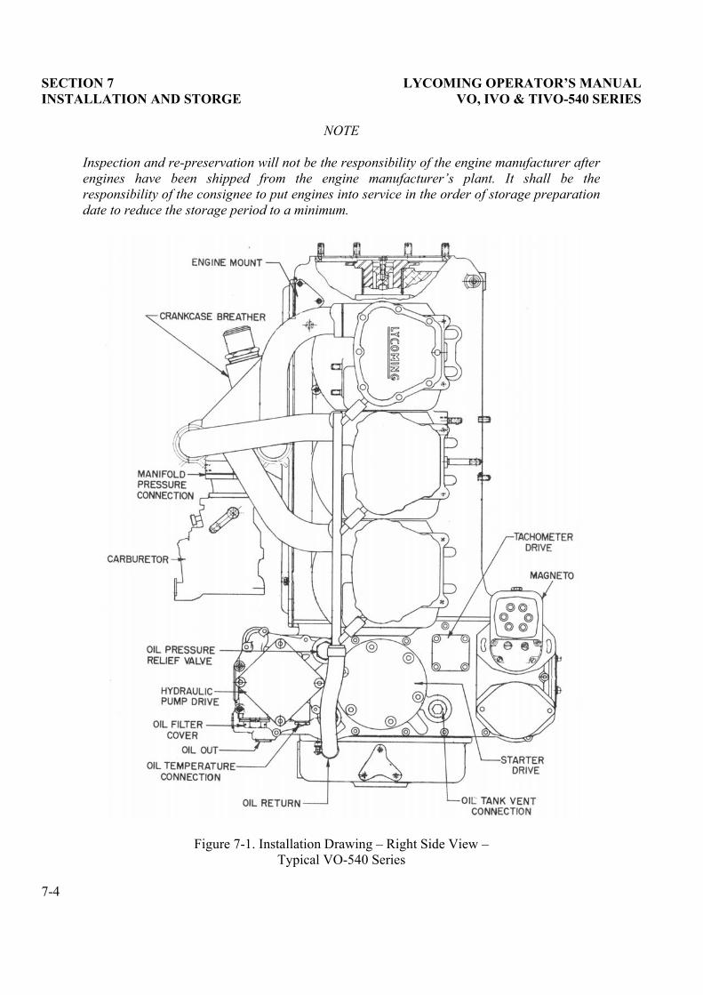
SECTION 7 LYCOMING OPERATOR�S MANUAL INSTALLATION AND STORGE VO, IVO & TIVO-540 SERIES
NOTE
Inspection and re-preservation will not be the responsibility of the engine manufacturer afterengines have been shipped from the engine manufacturer�s plant. It shall be the responsibility of the consignee to put engines into service in the order of storage preparationdate to reduce the storage period to a minimum.
Figure 7-1. Installation Drawing � Right Side View � Typical VO-540 Series
7-4
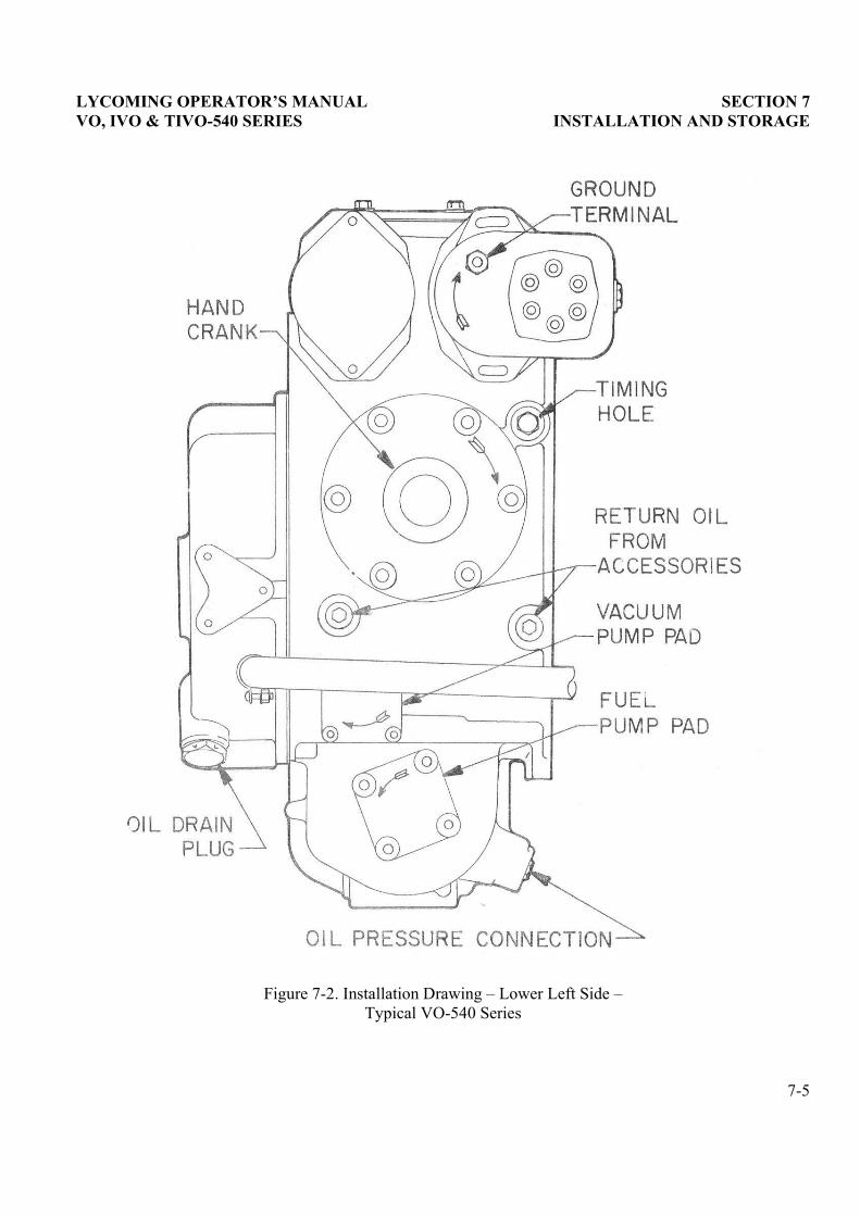
LYCOMING OPERATOR�S MANUAL SECTION 7 VO, IVO & TIVO-540 SERIES INSTALLATION AND STORAGE
Figure 7-2. Installation Drawing � Lower Left Side � Typical VO-540 Series
7-5

This Page Intentionally Left Blank.
LYCOMING OPERATOR�S MANUAL
SECTION 8TABLES
Page
Table of Limits ............................................................................................................................................. 8-1
Full Throttle HP at Altitude........................................................................................................................ 8-2
Table of Speed Equivalents ......................................................................................................................... 8-2
Centigrade � Fahrenheit Conversion ......................................................................................................... 8-3
Inch � Fraction Conversions ....................................................................................................................... 8-4

This Page Intentionally Left Blank.
LYCOMING OPERATOR�S MANUAL SECTION 8 VO, IVO & TIVO-540 SERIES TABLES
SECTION 8
TABLES
FOR TIGHTENING TORQUE RECOMMENDATIONS AND INFORMATION
CONCERNING TOLERANCES AND DIMENSIONS THAT MUST BE MAINTAINED
IN LYCOMING AIRCRAFT ENGINES, CONSULT LATEST REVISION OF SPECIAL
SERVICE PUBLICATION NO. SSP-1776.
CONSULT LATEST REVISION OF SERVICE INSTRUCTION NO. 1029 FOR
INFORMATION PERTINENT TO CORRECTLY INSTALLING CYLINDER
ASSEMBLY.
8-1

SECTION 8 LYCOMING OPERATOR�S MANUAL TABLES VO, IVO & TIVO-540 SERIES
FULL THROTTLE HP AT ALTITUDE(Normally Aspirated Engines)
AltitudeFt.
% S.L.H.P.
AltitudeFt.
% S.L.H.P.
AltitudeFt.
% S.L.H.P.
0 100 10,000 70.8 19,500 49.1500 98.5 11,000 68.3 20,000 48.0
1,000 96.8 12,000 65.8 20,500 47.62,000 93.6 13,000 63.4 21,000 46.02,500 92.0 14,000 61.0 21,500 45.23,000 90.5 15,000 58.7 22,000 44.04,000 87.5 16,000 56.5 22,500 43.35,000 84.6 17,000 54.3 23,000 42.26,000 81.7 17,500 53.1 23,500 41.47,000 78.9 18,000 52.1 24,000 40.38,000 76.2 18,500 51.4 24,500 39.59,000 73.5 19,000 50.0 25,000 38.5
TABLE OF SPEED EQUIVALENTS
Sec./Mi. M.P.H. Sec./Mi. M.P.H. Sec./Mi. M.P.H.
72.0 50 24.0 150 14.4 25060.0 60 22.5 160 13.8 26051.4 70 21.2 170 13.3 27045.0 80 20.0 180 12.8 28040.0 90 18.9 190 12.4 29036.0 100 18.0 200 12.0 30032.7 110 17.1 210 11.6 31030.0 120 16.4 220 11.2 32027.7 130 15.6 230 10.9 33025.7 140 15.0 240 10.6 340
8-2
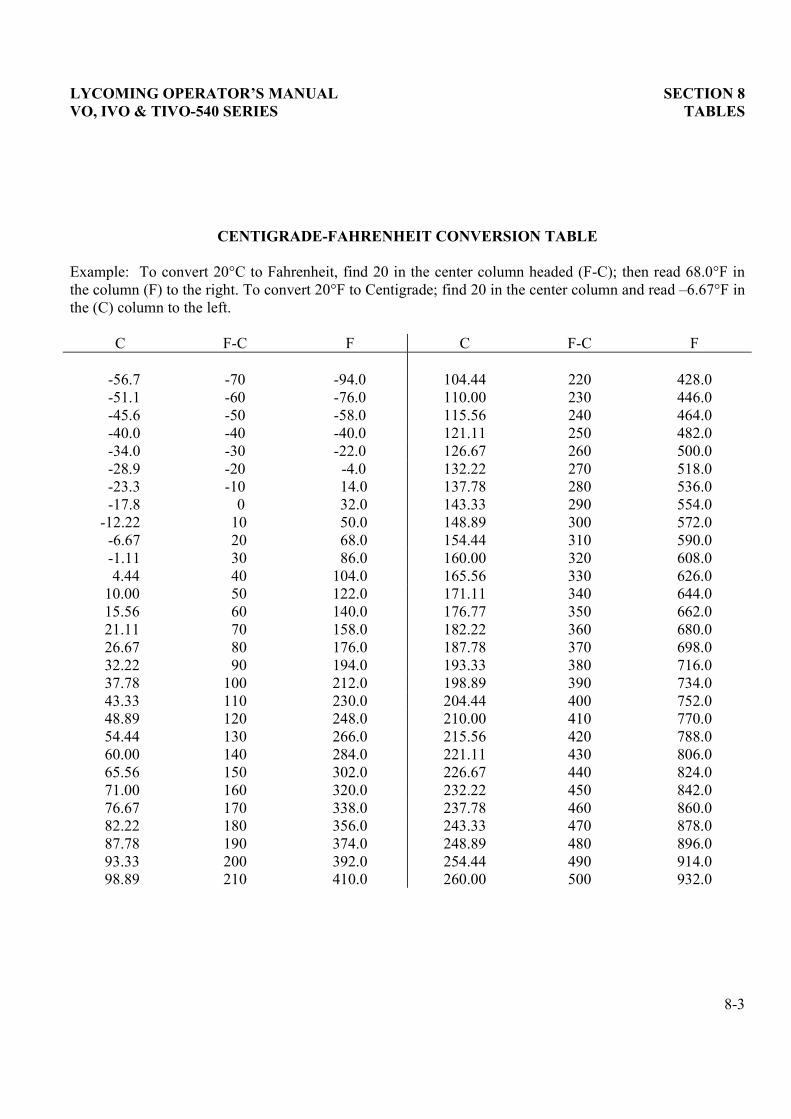
LYCOMING OPERATOR�S MANUAL SECTION 8 VO, IVO & TIVO-540 SERIES TABLES
CENTIGRADE-FAHRENHEIT CONVERSION TABLE
Example: To convert 20°C to Fahrenheit, find 20 in the center column headed (F-C); then read 68.0°F inthe column (F) to the right. To convert 20°F to Centigrade; find 20 in the center column and read �6.67°F in the (C) column to the left.
C F-C F C F-C F
-56.7 -70 -94.0 104.44 220 428.0-51.1 -60 -76.0 110.00 230 446.0-45.6 -50 -58.0 115.56 240 464.0-40.0 -40 -40.0 121.11 250 482.0-34.0 -30 -22.0 126.67 260 500.0-28.9 -20 -4.0 132.22 270 518.0-23.3 -10 14.0 137.78 280 536.0-17.8 0 32.0 143.33 290 554.0
-12.22 10 50.0 148.89 300 572.0-6.67 20 68.0 154.44 310 590.0-1.11 30 86.0 160.00 320 608.04.44 40 104.0 165.56 330 626.0
10.00 50 122.0 171.11 340 644.015.56 60 140.0 176.77 350 662.021.11 70 158.0 182.22 360 680.026.67 80 176.0 187.78 370 698.032.22 90 194.0 193.33 380 716.037.78 100 212.0 198.89 390 734.043.33 110 230.0 204.44 400 752.048.89 120 248.0 210.00 410 770.054.44 130 266.0 215.56 420 788.060.00 140 284.0 221.11 430 806.065.56 150 302.0 226.67 440 824.071.00 160 320.0 232.22 450 842.076.67 170 338.0 237.78 460 860.082.22 180 356.0 243.33 470 878.087.78 190 374.0 248.89 480 896.093.33 200 392.0 254.44 490 914.098.89 210 410.0 260.00 500 932.0
8-3
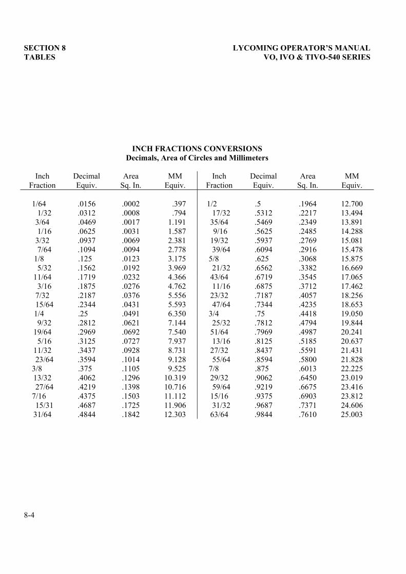
SECTION 8 LYCOMING OPERATOR�S MANUAL TABLES VO, IVO & TIVO-540 SERIES
INCH FRACTIONS CONVERSIONSDecimals, Area of Circles and Millimeters
InchFraction
DecimalEquiv.
AreaSq. In.
MMEquiv.
InchFraction
DecimalEquiv.
AreaSq. In.
MMEquiv.
1/64 .0156 .0002 .397 1/2 .5 .1964 12.7001/32 .0312 .0008 .794 17/32 .5312 .2217 13.494
3/64 .0469 .0017 1.191 35/64 .5469 .2349 13.8911/16 .0625 .0031 1.587 9/16 .5625 .2485 14.288
3/32 .0937 .0069 2.381 19/32 .5937 .2769 15.0817/64 .1094 .0094 2.778 39/64 .6094 .2916 15.478
1/8 .125 .0123 3.175 5/8 .625 .3068 15.8755/32 .1562 .0192 3.969 21/32 .6562 .3382 16.669
11/64 .1719 .0232 4.366 43/64 .6719 .3545 17.0653/16 .1875 .0276 4.762 11/16 .6875 .3712 17.462
7/32 .2187 .0376 5.556 23/32 .7187 .4057 18.25615/64 .2344 .0431 5.593 47/64 .7344 .4235 18.6531/4 .25 .0491 6.350 3/4 .75 .4418 19.0509/32 .2812 .0621 7.144 25/32 .7812 .4794 19.844
19/64 .2969 .0692 7.540 51/64 .7969 .4987 20.2415/16 .3125 .0727 7.937 13/16 .8125 .5185 20.637
11/32 .3437 .0928 8.731 27/32 .8437 .5591 21.43123/64 .3594 .1014 9.128 55/64 .8594 .5800 21.828
3/8 .375 .1105 9.525 7/8 .875 .6013 22.22513/32 .4062 .1296 10.319 29/32 .9062 .6450 23.01927/64 .4219 .1398 10.716 59/64 .9219 .6675 23.416
7/16 .4375 .1503 11.112 15/16 .9375 .6903 23.81215/31 .4687 .1725 11.906 31/32 .9687 .7371 24.606
31/64 .4844 .1842 12.303 63/64 .9844 .7610 25.003
8-4