voice processing system kx-tvm200 model no. kx … · thank you for purchasing a panasonic voice...
TRANSCRIPT

Document Version 2.0 2007/10
Getting StartedVoice Processing System
Model No. KX-TVM50KX-TVM200
Thank you for purchasing a Panasonic Voice Processing System. This manual shows you how to install andprogramme this product so that you can operate the basic features.For detailed information, refer to the Installation Manual.
KX-TVM50/KX-TVM200: Version 2.0
Table of Contents1 Before Installation ....................................................................................31.1 Unpacking .......................................................................................................................31.2 Names and Locations ....................................................................................................4
2 Installation ................................................................................................62.1 Installation Overview .....................................................................................................62.2 Removing the Cable Cover ............................................................................................72.3 Opening the Front Cover ...............................................................................................82.4 Removing the Dummy Cover Plates .............................................................................92.5 Installing Optional Cards in the KX-TVM50 ...............................................................102.6 Installing Port Cards in the KX-TVM200 .....................................................................132.7 Connecting the KX-TVM50 to the KX-TDA30 .............................................................162.8 Connecting the KX-TVM200 to the KX-TDA100 .........................................................172.9 Connecting the VPS to a PC or LAN ...........................................................................182.10 Frame Earth Connection ..............................................................................................192.11 Connecting the AC Adaptor ........................................................................................202.12 Securing the Cables .....................................................................................................222.13 Initialising the VPS During Installation ......................................................................242.14 Closing the Front Cover ..............................................................................................252.15 Attaching the Cable Cover ..........................................................................................262.16 Wall Mounting ...............................................................................................................272.16.1 Wall Mounting the VPS ..................................................................................................272.16.2 Wall Mounting the AC Adaptor .......................................................................................28
3 KX-TDA Series PBX Programming for DPT Programming .................323.1 Assignment of VM (DPT) Group ..................................................................................323.2 Assignment of VM (DPT) Extension Ports .................................................................33
4 Programming the VPS ...........................................................................344.1 Installing KX-TVM Maintenance Console ...................................................................344.2 Starting KX-TVM Maintenance Console .....................................................................364.3 Quick Setup ..................................................................................................................394.4 LAN Settings .................................................................................................................484.5 E-mail Integration Settings ..........................................................................................49
5 System Prompts Customisation ...........................................................515.1 System Prompts Customisation .................................................................................51
2 Getting Started Document Version 2.0 2007/10
1 Before Installation1.1 Unpacking
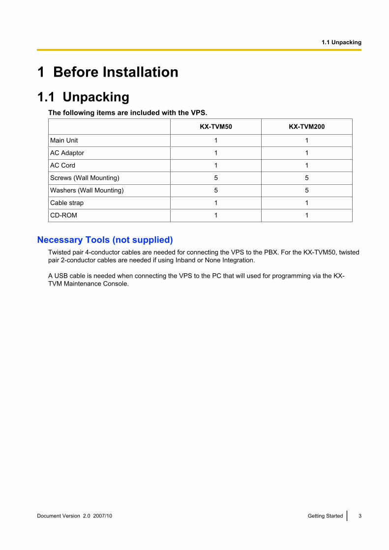
The following items are included with the VPS.
KX-TVM50 KX-TVM200
Main Unit 1 1
AC Adaptor 1 1
AC Cord 1 1
Screws (Wall Mounting) 5 5
Washers (Wall Mounting) 5 5
Cable strap 1 1
CD-ROM 1 1
Necessary Tools (not supplied)Twisted pair 4-conductor cables are needed for connecting the VPS to the PBX. For the KX-TVM50, twistedpair 2-conductor cables are needed if using Inband or None Integration.
A USB cable is needed when connecting the VPS to the PC that will used for programming via the KX-TVM Maintenance Console.
Document Version 2.0 2007/10 Getting Started 3
1.1 Unpacking
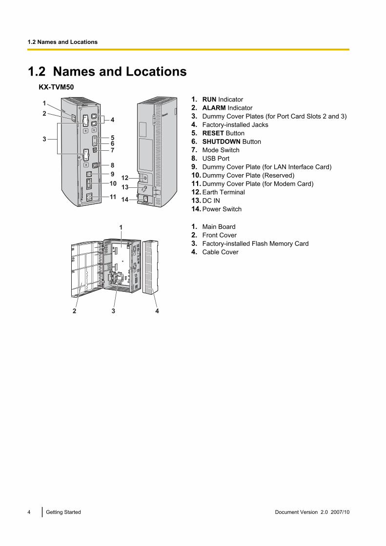
1.2 Names and LocationsKX-TVM50
56
4
8
9
10
11
7
13
12
14
3
2
11. RUN Indicator2. ALARM Indicator3. Dummy Cover Plates (for Port Card Slots 2 and 3)4. Factory-installed Jacks5. RESET Button6. SHUTDOWN Button7. Mode Switch8. USB Port9. Dummy Cover Plate (for LAN Interface Card)10. Dummy Cover Plate (Reserved)11. Dummy Cover Plate (for Modem Card)12. Earth Terminal13. DC IN14. Power Switch
1
32 4
1. Main Board2. Front Cover3. Factory-installed Flash Memory Card4. Cable Cover
4 Getting Started Document Version 2.0 2007/10
1.2 Names and Locations
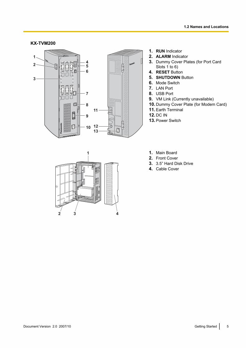
KX-TVM200
7
6
5
4
8
9
10 12
11
13
3
2
1
1. RUN Indicator2. ALARM Indicator3. Dummy Cover Plates (for Port Card
Slots 1 to 6)4. RESET Button5. SHUTDOWN Button6. Mode Switch7. LAN Port8. USB Port9. VM Link (Currently unavailable)10. Dummy Cover Plate (for Modem Card)11. Earth Terminal12. DC IN13. Power Switch
1
2 3 4
1. Main Board2. Front Cover3. 3.5” Hard Disk Drive4. Cable Cover
Document Version 2.0 2007/10 Getting Started 5
1.2 Names and Locations

2 Installation2.1 Installation Overview
The following is an overview of the steps needed to prepare the VPS hardware for use. Refer to the InstallationManual when installing optional cards or hardware.
CAUTIONThe information below is only intended as an overview of the installation process. When installing the VPS,refer to the information provided in this document or to the Installation Manual for detailed instructions.
1. Remove the cable cover.2. KX-TVM200 only: Install the port cards.3. Connect the VPS to the appropriate extension ports of the PBX.4. Connect the VPS to the PC to be used for programming.5. Connect the VPS to earth.6. Connect the AC adaptor to the VPS and to the power outlet.7. Secure the cables.8. Initialise the VPS.9. Attach the cable cover.10. Wall mount the VPS and AC adaptor.
6 Getting Started Document Version 2.0 2007/10
2.1 Installation Overview
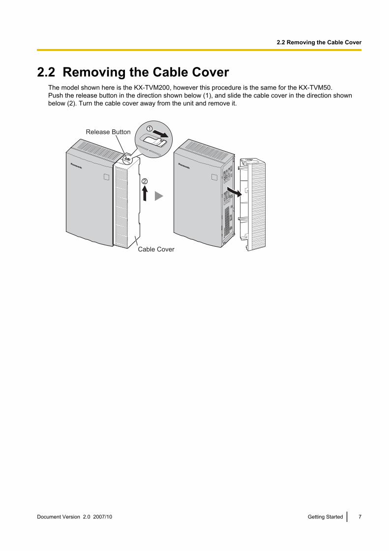
2.2 Removing the Cable CoverThe model shown here is the KX-TVM200, however this procedure is the same for the KX-TVM50.Push the release button in the direction shown below (1), and slide the cable cover in the direction shownbelow (2). Turn the cable cover away from the unit and remove it.
1Release Button
Cable Cover
Document Version 2.0 2007/10 Getting Started 7
2.2 Removing the Cable Cover

2.3 Opening the Front CoverThe model shown here is the KX-TVM200, however this procedure is the same for the KX-TVM50.For KX-TVM50:This procedure is not necessary if you do not plan on installing optional cards in the KX-TVM50.1. Remove the 3 screws.
Screw
2. While holding both tabs located on the sides of the front cover, swing the cover open as shown.
3. To remove the front cover completely during installation, hold the front cover open at a 45° angle, then liftthe cover away from the unit as shown.
8 Getting Started Document Version 2.0 2007/10
2.3 Opening the Front Cover
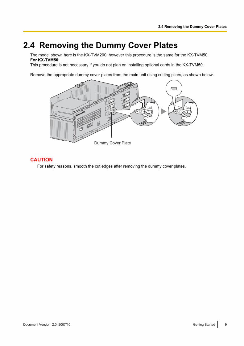
2.4 Removing the Dummy Cover PlatesThe model shown here is the KX-TVM200, however this procedure is the same for the KX-TVM50.For KX-TVM50:This procedure is not necessary if you do not plan on installing optional cards in the KX-TVM50.
Remove the appropriate dummy cover plates from the main unit using cutting pliers, as shown below.
Dummy Cover Plate
CAUTIONFor safety reasons, smooth the cut edges after removing the dummy cover plates.
Document Version 2.0 2007/10 Getting Started 9
2.4 Removing the Dummy Cover Plates
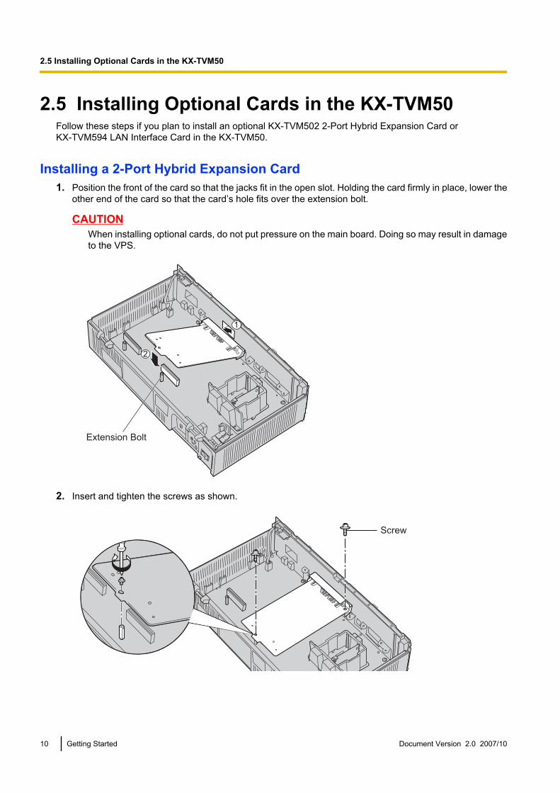
2.5 Installing Optional Cards in the KX-TVM50Follow these steps if you plan to install an optional KX-TVM502 2-Port Hybrid Expansion Card orKX-TVM594 LAN Interface Card in the KX-TVM50.
Installing a 2-Port Hybrid Expansion Card1. Position the front of the card so that the jacks fit in the open slot. Holding the card firmly in place, lower the
other end of the card so that the card’s hole fits over the extension bolt.
CAUTIONWhen installing optional cards, do not put pressure on the main board. Doing so may result in damageto the VPS.
2
1
Extension Bolt
2. Insert and tighten the screws as shown.
Screw
10 Getting Started Document Version 2.0 2007/10
2.5 Installing Optional Cards in the KX-TVM50

NoteThe KX-TVM502 operates at SELV.
Installing the LAN Interface Card1. Insert the card between the guide rails and slide it down as shown.2. Secure the latch by flipping it toward the centre of the card and slightly pressing down on it.
CAUTIONWhen installing optional cards, do not put pressure on the main board. Doing so may result in damageto the VPS.
Document Version 2.0 2007/10 Getting Started 11
2.5 Installing Optional Cards in the KX-TVM50
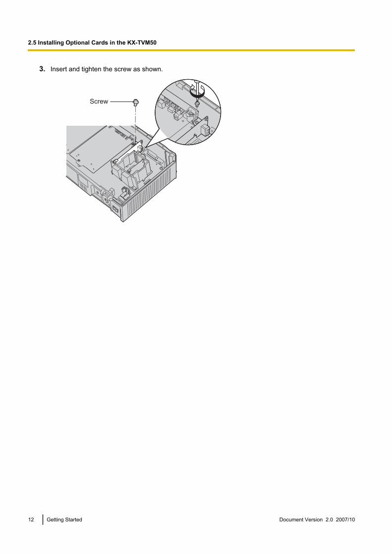
3. Insert and tighten the screw as shown.
Screw
12 Getting Started Document Version 2.0 2007/10
2.5 Installing Optional Cards in the KX-TVM50
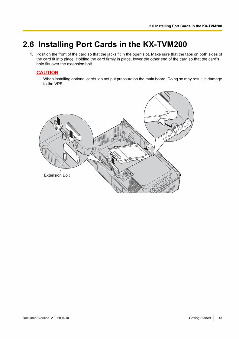
2.6 Installing Port Cards in the KX-TVM2001. Position the front of the card so that the jacks fit in the open slot. Make sure that the tabs on both sides of
the card fit into place. Holding the card firmly in place, lower the other end of the card so that the card’shole fits over the extension bolt.
CAUTIONWhen installing optional cards, do not put pressure on the main board. Doing so may result in damageto the VPS.
Extension Bolt
1
2
Document Version 2.0 2007/10 Getting Started 13
2.6 Installing Port Cards in the KX-TVM200
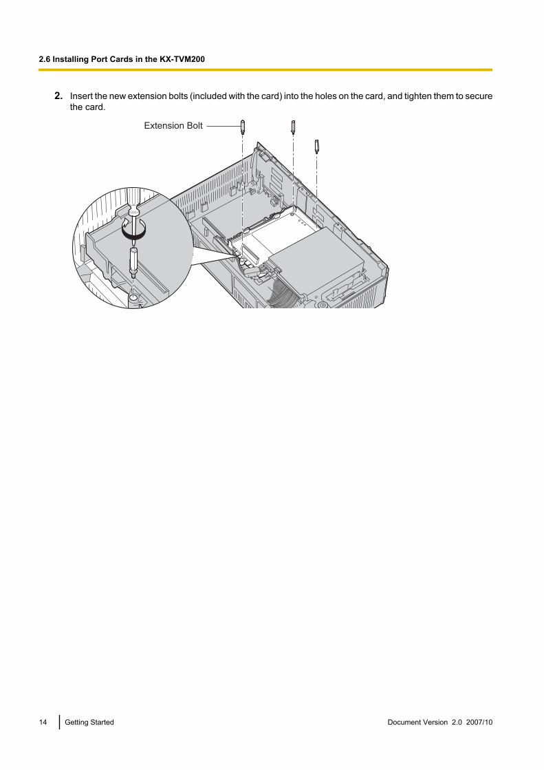
2. Insert the new extension bolts (included with the card) into the holes on the card, and tighten them to securethe card.
Extension Bolt
14 Getting Started Document Version 2.0 2007/10
2.6 Installing Port Cards in the KX-TVM200
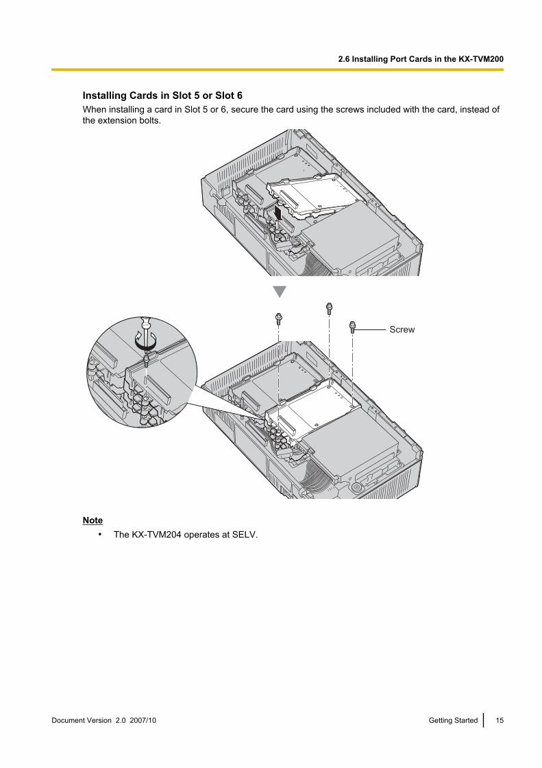
Installing Cards in Slot 5 or Slot 6When installing a card in Slot 5 or 6, secure the card using the screws included with the card, instead ofthe extension bolts.
Screw
Note• The KX-TVM204 operates at SELV.
Document Version 2.0 2007/10 Getting Started 15
2.6 Installing Port Cards in the KX-TVM200

2.7 Connecting the KX-TVM50 to the KX-TDA30Note
• 4-conductor cables must be used in order to use DPT Integration.• For DPT Integration, jack 1 must be connected to the lowest numbered port of the Voice Mail group
assigned through PBX programming.
Connection Example (Factory-installed Jacks, DPT Integration Mode)
PBX (KX-TDA30)
Slot 1
Port 2
Port 1
Port 4
Port 3
Port 2
Port 1
KX-TVM50
Assigned as VM (DPT) ports
Jack 1
Jack 2
Factory- installed Jacks
DLC4 Card
01
02
03
01
02
03
Jack 2
Jack 1
16 Getting Started Document Version 2.0 2007/10
2.7 Connecting the KX-TVM50 to the KX-TDA30

2.8 Connecting the KX-TVM200 to the KX-TDA100Note
• 4-conductor cables must be used in order to use DPT Integration.• For DPT Integration, the lowest numbered jack of the VPS must be connected to the lowest numbered
port of the Voice Mail group assigned through PBX programming.
Connection Example (KX-TVM204 ´ 6, DPT Integration Mode)
PBX (KX-TDA100)
Slot 1
Port 4
Port 3
Port 2
Port 1
Port 4
Port 3
Port 2
Port 1
Port 8
Port 7
Port 6
Port 5
Port 12
Port 11
Port 10
Port 9
Port 16
Port 15
Port 14
Port 13
KX-TVM200
Assigned as VM (DPT) ports
Jack 1
Jack 2
KX-TVM204
Slot 3
Port 10
Port 11
Port 12
Port 9 Jack 5
Jack 6
KX-TVM204
Slot 5
Port 18
Port 17
Port 19Port 20
Port 21
Port 22
Port 23Port 24
Jack 10
Jack 9
KX-TVM204
Slot 6
Jack 12
Jack 11
KX-TVM204
Slot 4
Port 14
Port 13
Port 15
Port 16
Jack 7
Jack 8
KX-TVM204
Slot 2
Port 8Port 7
Port 6Port 5 Jack 3
Jack 4
KX-TVM204
DLC16 Card
To KX-TVM200
12
11
10
9
8
7
6
5
4
3
2
101
02
03
04
05
06
01
02
03
04
05
06
Jack
Jack 12
Jack 8
Jack 4
Jack 3
Jack 7
Jack 2
Jack 1
Jack 11
Jack 10
Jack 9
Jack 6
Jack 5
Document Version 2.0 2007/10 Getting Started 17
2.8 Connecting the KX-TVM200 to the KX-TDA100
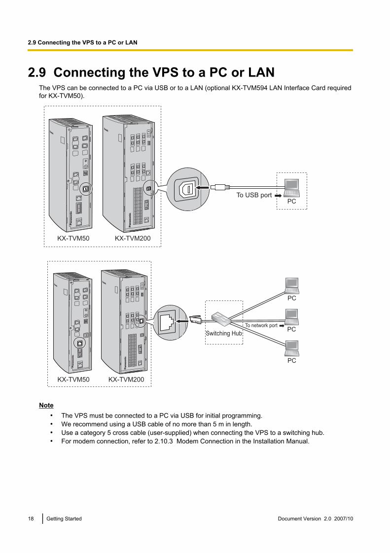
2.9 Connecting the VPS to a PC or LANThe VPS can be connected to a PC via USB or to a LAN (optional KX-TVM594 LAN Interface Card requiredfor KX-TVM50).
PCTo USB port
KX-TVM200KX-TVM50
To network port
Switching Hub
PC
PC
PC
KX-TVM200KX-TVM50
Note• The VPS must be connected to a PC via USB for initial programming.• We recommend using a USB cable of no more than 5 m in length.• Use a category 5 cross cable (user-supplied) when connecting the VPS to a switching hub.• For modem connection, refer to 2.10.3 Modem Connection in the Installation Manual.
18 Getting Started Document Version 2.0 2007/10
2.9 Connecting the VPS to a PC or LAN
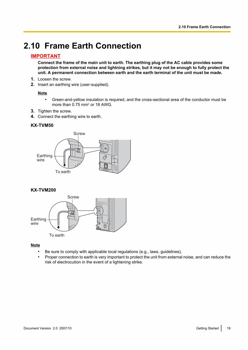
2.10 Frame Earth ConnectionIMPORTANT
Connect the frame of the main unit to earth. The earthing plug of the AC cable provides someprotection from external noise and lightning strikes, but it may not be enough to fully protect theunit. A permanent connection between earth and the earth terminal of the unit must be made.
1. Loosen the screw.2. Insert an earthing wire (user-supplied).
Note• Green-and-yellow insulation is required, and the cross-sectional area of the conductor must be
more than 0.75 mm2 or 18 AWG.3. Tighten the screw.4. Connect the earthing wire to earth.
KX-TVM50
Screw
Earthingwire
To earth
KX-TVM200Screw
Earthing wire
To earth
Note• Be sure to comply with applicable local regulations (e.g., laws, guidelines).• Proper connection to earth is very important to protect the unit from external noise, and can reduce the
risk of electrocution in the event of a lightening strike.
Document Version 2.0 2007/10 Getting Started 19
2.10 Frame Earth Connection
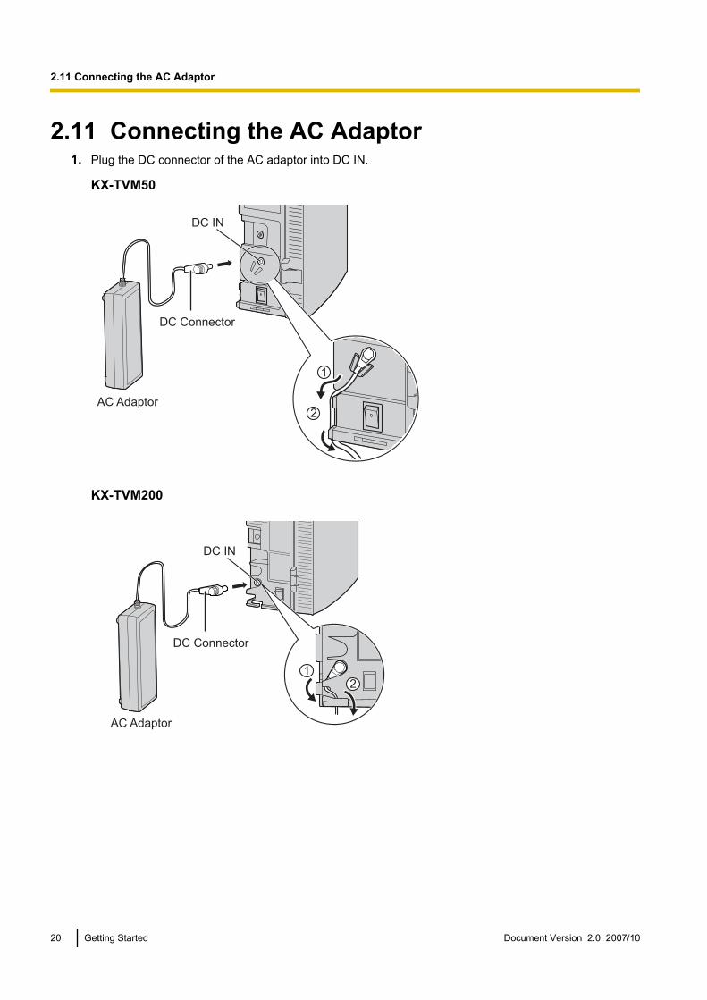
2.11 Connecting the AC Adaptor1. Plug the DC connector of the AC adaptor into DC IN.
KX-TVM50
AC Adaptor
DC Connector
DC IN
2
1
KX-TVM200
AC Adaptor
DC Connector
DC IN
21
20 Getting Started Document Version 2.0 2007/10
2.11 Connecting the AC Adaptor

2. Confirm that the VPS power switch is in the “OFF” position, then plug the AC cord into the AC adaptor,then plug the other end into an AC outlet.
AC Adaptor
AC Cord
To AC outlet
IMPORTANTKX-TVM50: Use only the included Panasonic AC adaptor, part number PSLP1322.KX-TVM200: Use only the included Panasonic AC adaptor, part number PSLP1244 or PSLP1434,or the KX-A236 Additional AC Adaptor.
Document Version 2.0 2007/10 Getting Started 21
2.11 Connecting the AC Adaptor
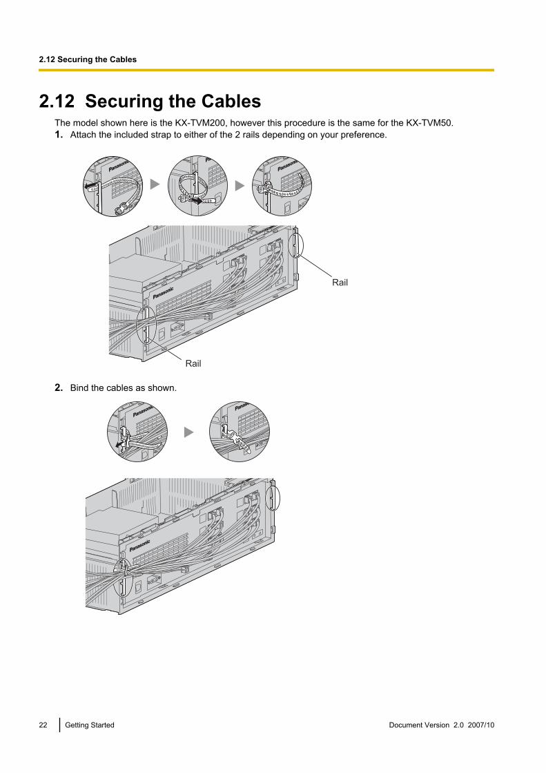
2.12 Securing the CablesThe model shown here is the KX-TVM200, however this procedure is the same for the KX-TVM50.1. Attach the included strap to either of the 2 rails depending on your preference.
Rail
Rail
2. Bind the cables as shown.
22 Getting Started Document Version 2.0 2007/10
2.12 Securing the Cables
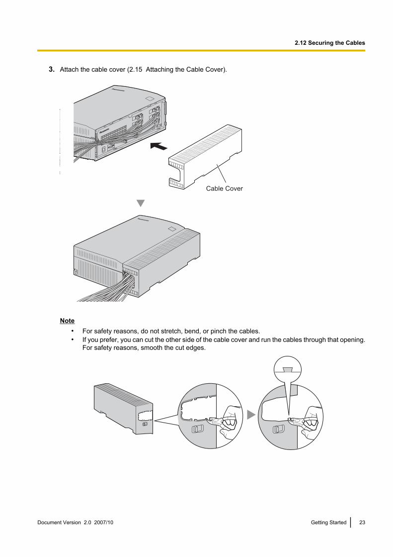
3. Attach the cable cover (2.15 Attaching the Cable Cover).
Cable Cover
Note• For safety reasons, do not stretch, bend, or pinch the cables.• If you prefer, you can cut the other side of the cable cover and run the cables through that opening.
For safety reasons, smooth the cut edges.
Document Version 2.0 2007/10 Getting Started 23
2.12 Securing the Cables
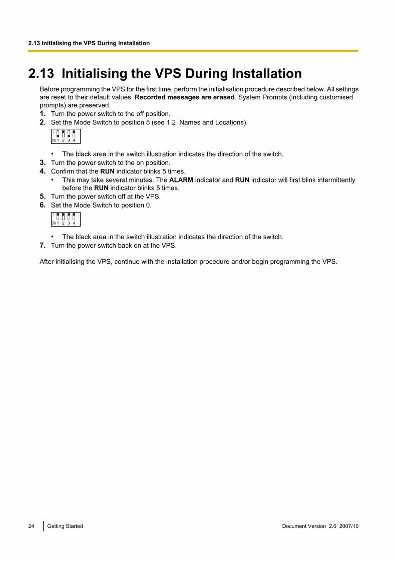
2.13 Initialising the VPS During InstallationBefore programming the VPS for the first time, perform the initialisation procedure described below. All settingsare reset to their default values. Recorded messages are erased. System Prompts (including customisedprompts) are preserved.1. Turn the power switch to the off position.2. Set the Mode Switch to position 5 (see 1.2 Names and Locations).
• The black area in the switch illustration indicates the direction of the switch.3. Turn the power switch to the on position.4. Confirm that the RUN indicator blinks 5 times.
• This may take several minutes. The ALARM indicator and RUN indicator will first blink intermittentlybefore the RUN indicator blinks 5 times.
5. Turn the power switch off at the VPS.6. Set the Mode Switch to position 0.
• The black area in the switch illustration indicates the direction of the switch.7. Turn the power switch back on at the VPS.
After initialising the VPS, continue with the installation procedure and/or begin programming the VPS.
24 Getting Started Document Version 2.0 2007/10
2.13 Initialising the VPS During Installation
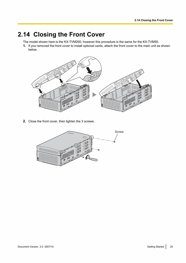
2.14 Closing the Front CoverThe model shown here is the KX-TVM200, however this procedure is the same for the KX-TVM50.1. If you removed the front cover to install optional cards, attach the front cover to the main unit as shown
below.
2. Close the front cover, then tighten the 3 screws.
Screw
Document Version 2.0 2007/10 Getting Started 25
2.14 Closing the Front Cover
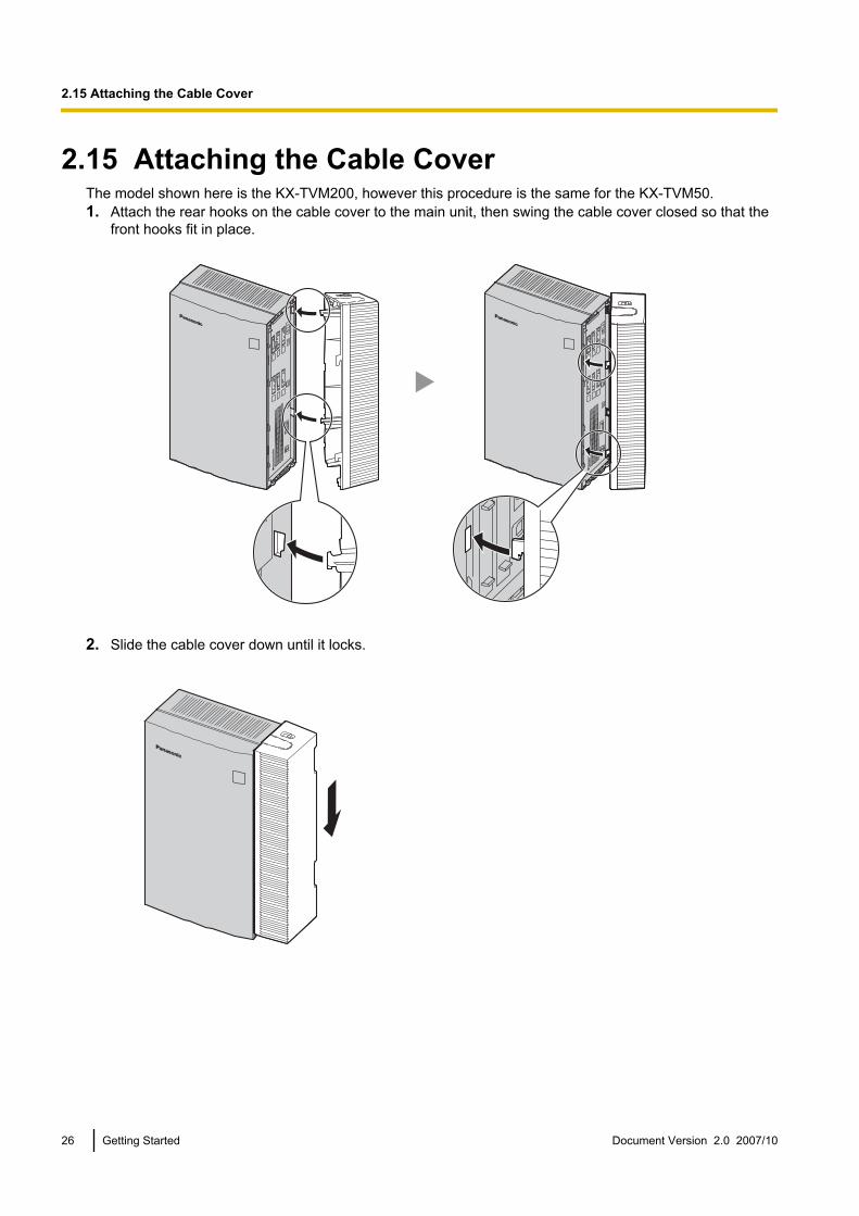
2.15 Attaching the Cable CoverThe model shown here is the KX-TVM200, however this procedure is the same for the KX-TVM50.1. Attach the rear hooks on the cable cover to the main unit, then swing the cable cover closed so that the
front hooks fit in place.
2. Slide the cable cover down until it locks.
26 Getting Started Document Version 2.0 2007/10
2.15 Attaching the Cable Cover

2.16 Wall Mounting2.16.1 Wall Mounting the VPSMounting on a Wooden Wall
1. Place the appropriate wall mounting template (found on the last 2 pages of this manual) on the wall to markthe locations where the 3 screws need to be placed.
2. Install the screws and washers (included) in the wall.
Washer
Drive the screwto this position.
Note• Drive the screws into the wall until each screw head is the same distance from the wall.• Install the screws perpendicular to the wall.
3. Mount the unit as shown.
Note• Do not block the openings of the unit. Allow space of at least 20 cm above and 10 cm on the sides
of the unit.• Make sure that the wall behind the unit is flat and free of obstructions so that the openings on the
back of the unit will not be blocked.• Be careful not to drop the unit.
Mounting on a Concrete or Mortar WallCAUTION
When driving the mounting screws into the wall, be careful to avoid touching any metalwork (metal/wirelaths, etc.), conduits, or electrical cables buried in the wall.
Document Version 2.0 2007/10 Getting Started 27
2.16.1 Wall Mounting the VPS
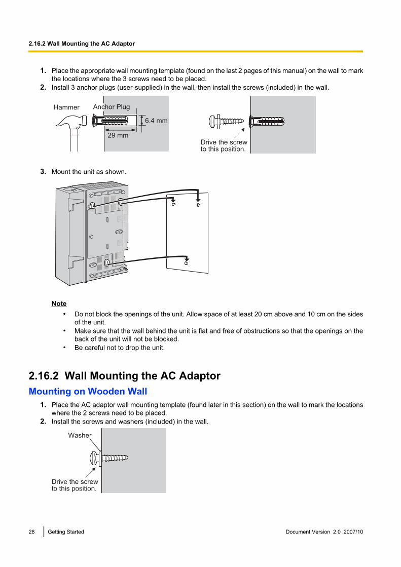
1. Place the appropriate wall mounting template (found on the last 2 pages of this manual) on the wall to markthe locations where the 3 screws need to be placed.
2. Install 3 anchor plugs (user-supplied) in the wall, then install the screws (included) in the wall.
Hammer
29 mm
Anchor Plug
6.4 mm
Drive the screwto this position.
3. Mount the unit as shown.
Note• Do not block the openings of the unit. Allow space of at least 20 cm above and 10 cm on the sides
of the unit.• Make sure that the wall behind the unit is flat and free of obstructions so that the openings on the
back of the unit will not be blocked.• Be careful not to drop the unit.
2.16.2 Wall Mounting the AC AdaptorMounting on Wooden Wall
1. Place the AC adaptor wall mounting template (found later in this section) on the wall to mark the locationswhere the 2 screws need to be placed.
2. Install the screws and washers (included) in the wall.
Washer
Drive the screwto this position.
28 Getting Started Document Version 2.0 2007/10
2.16.2 Wall Mounting the AC Adaptor

Note• Drive the screws into the wall until each screw head is the same distance from the wall.• Install the screws perpendicular to the wall.
3. Mount the AC adaptor as shown.
Mounting on Concrete or Mortar WallCAUTION
When driving the mounting screws into the wall, be careful to avoid touching any metalwork (metal/wirelaths, etc.), conduits, or electrical cables buried in the wall.
1. Place the AC adaptor wall mounting template (found later in this section) on the wall to mark the locationswhere the 2 screws need to be placed.
2. Install 2 anchor plugs (user-supplied) in the wall, then install the screws (included) in the wall.
Hammer
29 mm
Anchor Plug
6.4 mm
Drive the screwto this position.
Document Version 2.0 2007/10 Getting Started 29
2.16.2 Wall Mounting the AC Adaptor
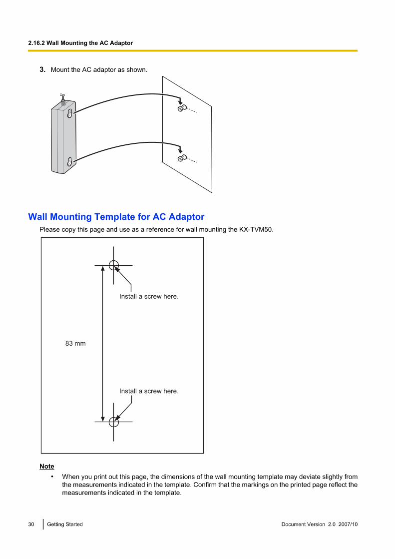
3. Mount the AC adaptor as shown.
Wall Mounting Template for AC AdaptorPlease copy this page and use as a reference for wall mounting the KX-TVM50.
83 mm
Install a screw here.
Install a screw here.
Note• When you print out this page, the dimensions of the wall mounting template may deviate slightly from
the measurements indicated in the template. Confirm that the markings on the printed page reflect themeasurements indicated in the template.
30 Getting Started Document Version 2.0 2007/10
2.16.2 Wall Mounting the AC Adaptor

Please copy this page and use as a reference for wall mounting the KX-TVM200.
Install a screw here.
Install a screw here.
110 mm
Note• When you print out this page, the dimensions of the wall mounting template may deviate slightly from
the measurements indicated in the template. Confirm that the markings on the printed page reflect themeasurements indicated in the template.
Document Version 2.0 2007/10 Getting Started 31
2.16.2 Wall Mounting the AC Adaptor
3 KX-TDA Series PBX Programming for DPTProgramming3.1 Assignment of VM (DPT) Group
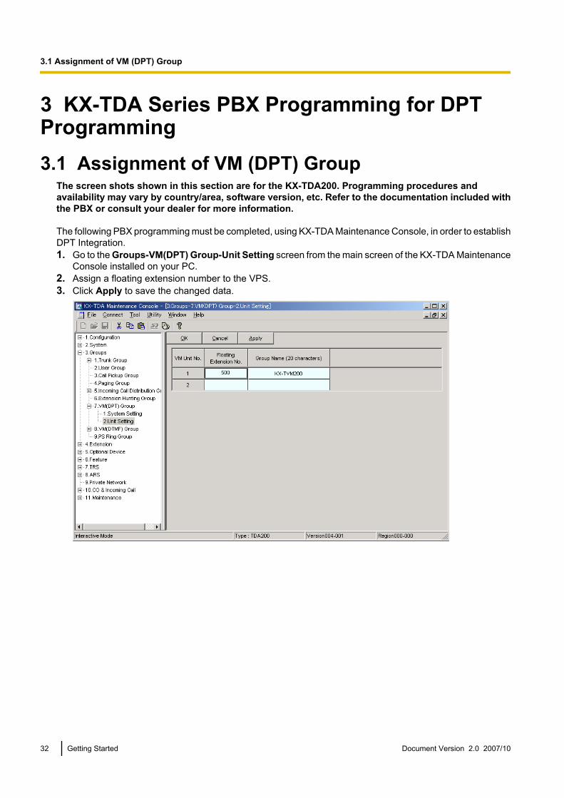
The screen shots shown in this section are for the KX-TDA200. Programming procedures andavailability may vary by country/area, software version, etc. Refer to the documentation included withthe PBX or consult your dealer for more information.
The following PBX programming must be completed, using KX-TDA Maintenance Console, in order to establishDPT Integration.1. Go to the Groups-VM(DPT) Group-Unit Setting screen from the main screen of the KX-TDA Maintenance
Console installed on your PC.2. Assign a floating extension number to the VPS.3. Click Apply to save the changed data.
32 Getting Started Document Version 2.0 2007/10
3.1 Assignment of VM (DPT) Group
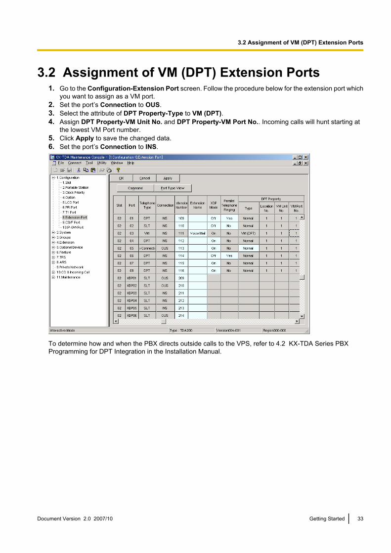
3.2 Assignment of VM (DPT) Extension Ports1. Go to the Configuration-Extension Port screen. Follow the procedure below for the extension port which
you want to assign as a VM port.2. Set the port’s Connection to OUS.3. Select the attribute of DPT Property-Type to VM (DPT).4. Assign DPT Property-VM Unit No. and DPT Property-VM Port No.. Incoming calls will hunt starting at
the lowest VM Port number.5. Click Apply to save the changed data.6. Set the port’s Connection to INS.
To determine how and when the PBX directs outside calls to the VPS, refer to 4.2 KX-TDA Series PBXProgramming for DPT Integration in the Installation Manual.
Document Version 2.0 2007/10 Getting Started 33
3.2 Assignment of VM (DPT) Extension Ports
4 Programming the VPS4.1 Installing KX-TVM Maintenance ConsoleSystem Requirements
Required Operating SystemMicrosoft® Windows® 2000, Windows XP Professional Service Pack 2, or Windows Vista® Business Edition
Minimum Hardware Requirements for Windows 2000, Windows XPCPU: 1.2 GHz Intel® Pentium® microprocessorHDD: 20 MB of available hard disk spaceRAM: 256 MB of available RAM
Minimum Hardware Requirements for Windows VistaCPU: 1.8 GHz Intel Pentium microprocessorHDD: 40 MB of available hard disk spaceRAM: 1 GB of available RAM
Password SecurityTo maintain system security, a password is required to perform system programming. We recommendchanging the default password the first time you access the VPS via KX-TVM Maintenance Console. Thedefault password can be changed by running the Quick Setup utility (see 4.3 Quick Setup) or by selectingSystem Security®Administrator®Password.
Warning to the Administrator regarding the system password1. To avoid unauthorized access to VPS settings, which could result in fraudulent dialling, do not disclose the
password.2. Please inform the customer of the importance of the password and the possible dangers if it becomes
known to others.3. Please change the password periodically.4. To prevent unauthorized access, we strongly recommend selecting a long and random password.5. If the system password is forgotten, you have to reset the VPS to its factory defaults and reprogram it.
Note• A Programmer Code, if set, is required to start KX-TVM Maintenance Console. You can set or delete
the Programmer Code by selecting Utility®Programmer Code. If no code is set, the KX-TVM Maintenance Console can be started and used, but a password is required to connect to the VPSand change VPS settings.
Installing KX-TVM Maintenance Console1. Copy the KX-TVM Maintenance Console setup file to a local drive on the PC. (Its icon
is shown here, on the left.)2. Double-click the setup file to run the installer.3. Follow the on-screen instructions provided by the installation wizard.4. Click Yes when prompted to copy the USB drivers, specify a location, then click OK.5. Click OK after the drivers have been copied to the local drive.6. Click Finish.
34 Getting Started Document Version 2.0 2007/10
4.1 Installing KX-TVM Maintenance Console

Note• To install or uninstall the software on a PC running Windows 2000 Professional or Windows XP
Professional, you must be logged in as a user that is in either the “Administrators” or “Power Users”group.
• When the VPS is first connected to the PC via USB, a wizard should appear and ask you to select theappropriate USB driver. Browse for and select the KX-TVM USB driver, which is copied to the localdrive during installation.
Document Version 2.0 2007/10 Getting Started 35
4.1 Installing KX-TVM Maintenance Console

4.2 Starting KX-TVM Maintenance ConsoleThe instructions listed below explain how to start KX-TVM Maintenance Console. These instructions are forwhen connecting to the VPS via USB.
Note• The screenshots shown here are for reference only, and may differ from the screens displayed on your
PC.• KX-TVM Maintenance Console uses English as the default language. See step 4 to change the
language.1. Click the KX-TVM Maintenance Console shortcut icon.
2. Select the appropriate VPS model and click OK.
3. The Set Default Parameters window is displayed the first time you start KX-TVM Maintenance Console.Select the TVM Type, PBX Type, and Integration Mode. Change the default parameters listed in the windowif necessary, then click OK.
Note• If you have already used KX-TVM Maintenance Console to change the Programmer Code, the
Enter Programmer Code dialogue box is displayed. Enter the previously set Programmer Code,then click OK.
36 Getting Started Document Version 2.0 2007/10
4.2 Starting KX-TVM Maintenance Console
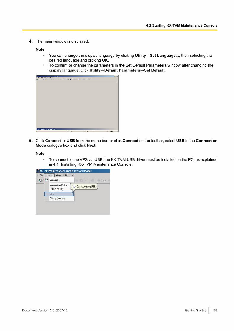
4. The main window is displayed.
Note• You can change the display language by clicking Utility®Set Language..., then selecting the
desired language and clicking OK.• To confirm or change the parameters in the Set Default Parameters window after changing the
display language, click Utility®Default Parameters®Set Default.
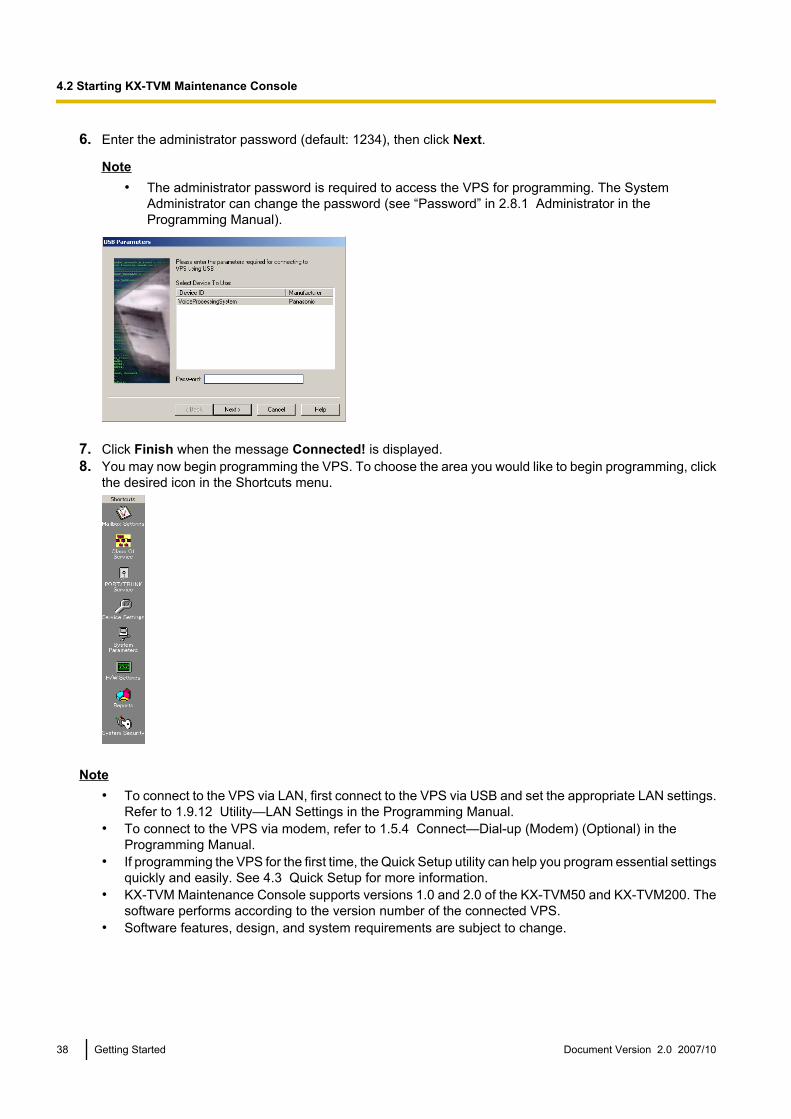
5. Click Connect ® USB from the menu bar, or click Connect on the toolbar, select USB in the ConnectionMode dialogue box and click Next.
Note• To connect to the VPS via USB, the KX-TVM USB driver must be installed on the PC, as explained
in 4.1 Installing KX-TVM Maintenance Console.
Document Version 2.0 2007/10 Getting Started 37
4.2 Starting KX-TVM Maintenance Console
6. Enter the administrator password (default: 1234), then click Next.
Note• The administrator password is required to access the VPS for programming. The System
Administrator can change the password (see “Password” in 2.8.1 Administrator in theProgramming Manual).
7. Click Finish when the message Connected! is displayed.8. You may now begin programming the VPS. To choose the area you would like to begin programming, click
the desired icon in the Shortcuts menu.
Note• To connect to the VPS via LAN, first connect to the VPS via USB and set the appropriate LAN settings.
Refer to 1.9.12 Utility—LAN Settings in the Programming Manual.• To connect to the VPS via modem, refer to 1.5.4 Connect—Dial-up (Modem) (Optional) in the
Programming Manual.• If programming the VPS for the first time, the Quick Setup utility can help you program essential settings
quickly and easily. See 4.3 Quick Setup for more information.• KX-TVM Maintenance Console supports versions 1.0 and 2.0 of the KX-TVM50 and KX-TVM200. The
software performs according to the version number of the connected VPS.• Software features, design, and system requirements are subject to change.
38 Getting Started Document Version 2.0 2007/10
4.2 Starting KX-TVM Maintenance Console

4.3 Quick SetupStarting Quick Setup
1. Start KX-TVM Maintenance Console and connect to the VPS (refer to 4.2 Starting KX-TVM MaintenanceConsole).
2. Click Utility ® Quick Setup... in the menu bar.
3. Click OK when the message is displayed.
Document Version 2.0 2007/10 Getting Started 39
4.3 Quick Setup
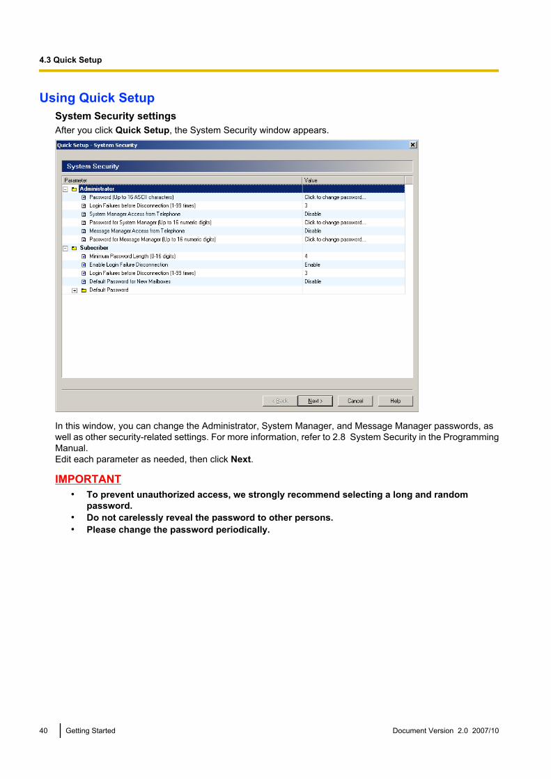
Using Quick SetupSystem Security settingsAfter you click Quick Setup, the System Security window appears.
In this window, you can change the Administrator, System Manager, and Message Manager passwords, aswell as other security-related settings. For more information, refer to 2.8 System Security in the ProgrammingManual.Edit each parameter as needed, then click Next.
IMPORTANT• To prevent unauthorized access, we strongly recommend selecting a long and random
password.• Do not carelessly reveal the password to other persons.• Please change the password periodically.
40 Getting Started Document Version 2.0 2007/10
4.3 Quick Setup
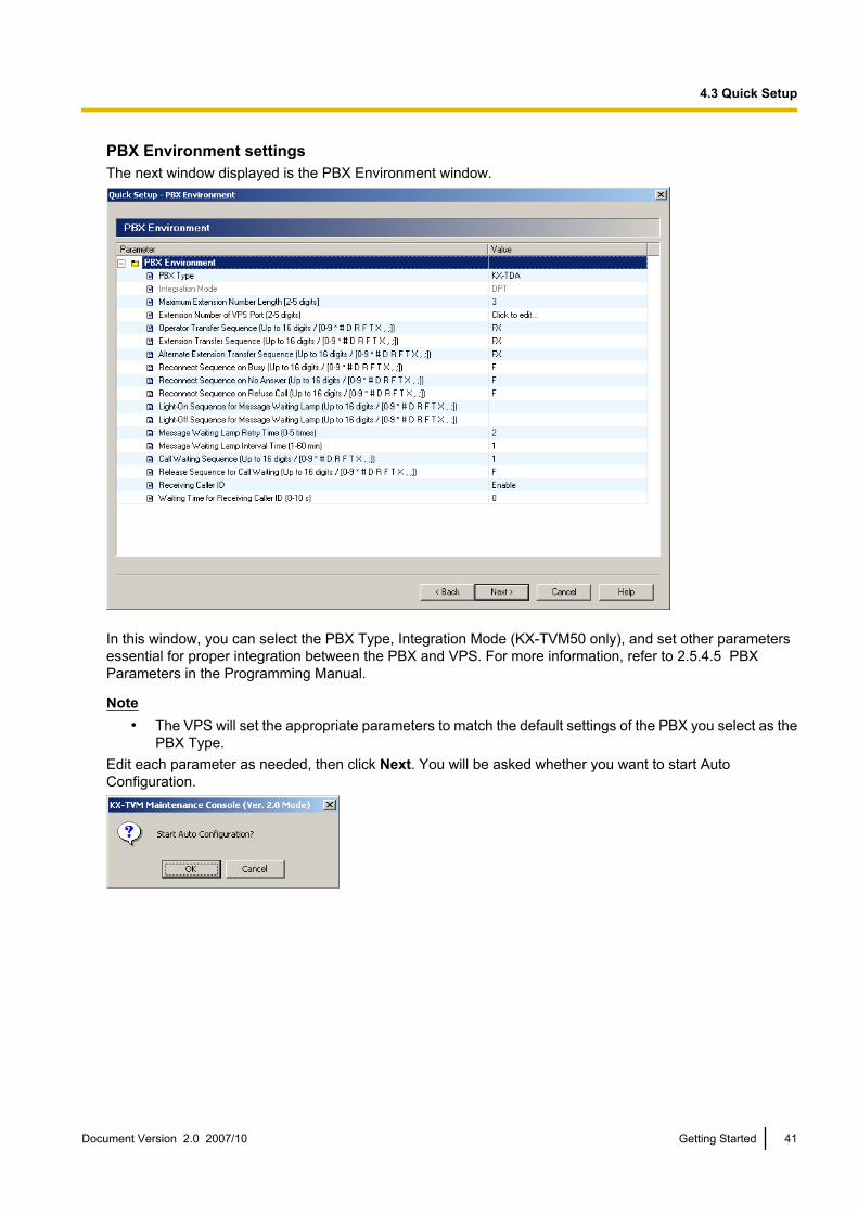
PBX Environment settingsThe next window displayed is the PBX Environment window.
In this window, you can select the PBX Type, Integration Mode (KX-TVM50 only), and set other parametersessential for proper integration between the PBX and VPS. For more information, refer to 2.5.4.5 PBXParameters in the Programming Manual.
Note• The VPS will set the appropriate parameters to match the default settings of the PBX you select as the
PBX Type.Edit each parameter as needed, then click Next. You will be asked whether you want to start AutoConfiguration.
Document Version 2.0 2007/10 Getting Started 41
4.3 Quick Setup

Click OK to start Auto Configuration.
Click Next when the button becomes available.
Create mailboxesThe next window displayed is the Select Extensions window. Extension data retrieved from the PBX isdisplayed.
Select the extensions for which you would like to create mailboxes, then click Next.
Note• Mailboxes will be created during Auto Configuration. The number of digits used for mailbox numbers
is 2 to 5 digits, depending on PBX programming.The Message Manager mailbox (General Delivery Mailbox) number will be 98, 998, 9998, or 99998.The System Manager mailbox number will be 99, 999, 9999, or 99999.If both 3-digit and 4-digit extension numbers are used by the PBX, the VPS will use 4-digit mailboxnumbers. When creating mailbox numbers for 3-digit extensions, a “0” will be added to the end of eachmailbox number.
42 Getting Started Document Version 2.0 2007/10
4.3 Quick Setup

Example of 3-digit extension numbers converted to 4-digit mailbox numbers:
Extension Numbers Mailbox Numbers
201 2010
202 2020
203 2030
2000 2000
2001 2001
2002 2002
• It is possible to program the VPS to allow mailbox numbers of mixed length.
Example of mixed length mailbox numbers:
Extension Numbers Mailbox Numbers
201 201
202 202
203 203
2000 2000
2001 2001
2002 2002
In order to allow mailbox numbers of mixed length, you must enter a special command using theCommands dialogue in the KX-TVM Maintenance Console. For more information, refer to6.1.3 Changing the Mailbox No. Length Mode in the Installation Manual.
Document Version 2.0 2007/10 Getting Started 43
4.3 Quick Setup

Mailbox settingsThe next window displayed is the Mailbox Edit window.
Edit, delete, or add mailboxes as needed, then click Next. For more information, refer to 2.1.3 MailboxParameters in the Programming Manual.
Note• The Mailbox Edit window allows you to set basic mailbox parameters only. Detailed mailbox settings
can be made after Quick Setup has finished, by clicking the Mailbox Settings icon under Shortcuts.
44 Getting Started Document Version 2.0 2007/10
4.3 Quick Setup
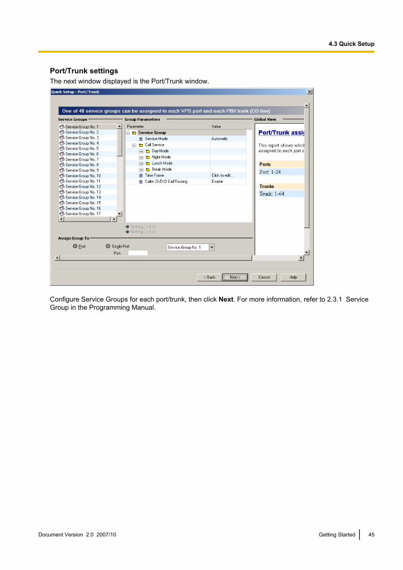
Port/Trunk settingsThe next window displayed is the Port/Trunk window.
Configure Service Groups for each port/trunk, then click Next. For more information, refer to 2.3.1 ServiceGroup in the Programming Manual.
Document Version 2.0 2007/10 Getting Started 45
4.3 Quick Setup
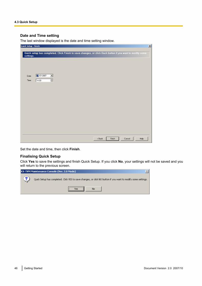
Date and Time settingThe last window displayed is the date and time setting window.
Set the date and time, then click Finish.
Finalising Quick SetupClick Yes to save the settings and finish Quick Setup. If you click No, your settings will not be saved and youwill return to the previous screen.
46 Getting Started Document Version 2.0 2007/10
4.3 Quick Setup

If you clicked Yes, the following screen is displayed as your settings are saved.
When Quick Setup is completed, the following screen will be displayed.
Note• If the VPS is connected to a KX-TD500, restart the VPS to bring the VPS online.
Document Version 2.0 2007/10 Getting Started 47
4.3 Quick Setup
4.4 LAN SettingsTo program the VPS over a LAN connection or to use E-mail Integration features, the VPS must first beconnected to the LAN and programmed accordingly.
Programming the VPS for LAN access1. Connect the PC to the VPS via USB (refer to 2.9 Connecting the VPS to a PC or LAN).2. Start KX-TVM Maintenance Console and connect to the VPS via USB (refer to 4.2 Starting KX-
TVM Maintenance Console).3. Click Utility in the menu bar.4. Select LAN Settings.5. Select “Obtain an IP address automatically”, or select “Use the following IP address:” and specify the IP
address, subnet mask, and default gateway.6. Select “Obtain DNS server address automatically“, or select “Use the following DNS server addresses:”
and specify the preferred and alternate DNS server addresses.7. To change the port number used for accessing the VPS over the LAN, click Advanced Settings, specify
the port number, then click OK, otherwise click OK to close the LAN Settings dialogue box.
Note• The port number setting is used for both LAN and modem connections to the VPS.• Consult the LAN administrator for the appropriate settings.• The VPS must be restarted after these settings are changed in order for them to take effect.
Accessing the VPS over the LAN1. Start KX-TVM Maintenance Console.2. From the Connect menu, select LAN (TCP/IP).3. Enter the IP address, port number, and password used to connect to the VPS.4. Click Next, then click Finish when the connection is completed.
48 Getting Started Document Version 2.0 2007/10
4.4 LAN Settings
4.5 E-mail Integration SettingsThe VPS can be programmed to send text and voice messages (as file attachments) to subscribers when theyhave new messages. The following settings must be made in order for the VPS to use E-mail Integrationfeatures. Consult the LAN administrator for the appropriate settings.
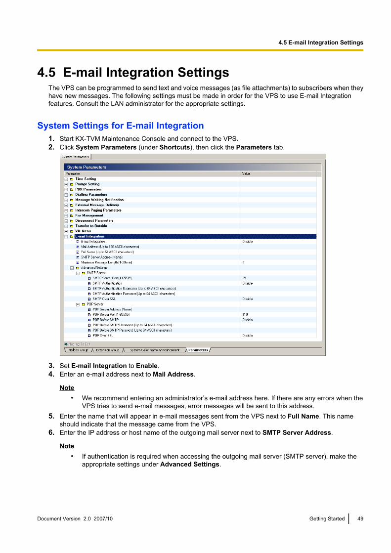
System Settings for E-mail Integration1. Start KX-TVM Maintenance Console and connect to the VPS.2. Click System Parameters (under Shortcuts), then click the Parameters tab.
3. Set E-mail Integration to Enable.4. Enter an e-mail address next to Mail Address.
Note• We recommend entering an administrator’s e-mail address here. If there are any errors when the
VPS tries to send e-mail messages, error messages will be sent to this address.5. Enter the name that will appear in e-mail messages sent from the VPS next to Full Name. This name
should indicate that the message came from the VPS.6. Enter the IP address or host name of the outgoing mail server next to SMTP Server Address.
Note• If authentication is required when accessing the outgoing mail server (SMTP server), make the
appropriate settings under Advanced Settings.
Document Version 2.0 2007/10 Getting Started 49
4.5 E-mail Integration Settings
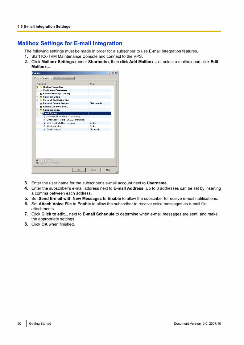
Mailbox Settings for E-mail IntegrationThe following settings must be made in order for a subscriber to use E-mail Integration features.1. Start KX-TVM Maintenance Console and connect to the VPS.2. Click Mailbox Settings (under Shortcuts), then click Add Mailbox... or select a mailbox and click Edit
Mailbox....
3. Enter the user name for the subscriber’s e-mail account next to Username.4. Enter the subscriber’s e-mail address next to E-mail Address. Up to 3 addresses can be set by inserting
a comma between each address.5. Set Send E-mail with New Messages to Enable to allow the subscriber to receive e-mail notifications.6. Set Attach Voice File to Enable to allow the subscriber to receive voice messages as e-mail file
attachments.7. Click Click to edit... next to E-mail Schedule to determine when e-mail messages are sent, and make
the appropriate settings.8. Click OK when finished.
50 Getting Started Document Version 2.0 2007/10
4.5 E-mail Integration Settings

5 System Prompts Customisation5.1 System Prompts Customisation
System prompts can be customised using KX-TVM Maintenance Console and an extension telephoneconnected to the PBX.
Note• The subscriber designated as the Message Manager can also customise system prompts using just
his or her extension telephone. For more information, refer to the “Message Manager’s Guide” in theManager’s Manual.
The System Prompts Customization screen is used to view, play, add, or delete system prompts. The SystemAdministrator can also check the prompt number and text for these prompts. The following categories of systemprompts can be customized from the System Prompts Customization screen:a. System Guidanceb. Custom Service Menusc. Company Greetingsd. Others
– Company Name– Language Select Menu– Hold Announce Menu– Mailbox Group List Label– Extension Group List Label– System Caller ID Name
Follow the steps to customise system prompts:1. Start KX-TVM Maintenance Console and connect to the VPS.2. Click Utility in the menu bar.3. Select System Prompts Customization.4. Select a tab in the System Prompts Customization dialogue box.
[Deleting Prompts]The System Administrator is able to delete the specific system prompt or the installed language used for systemprompts.
To delete a specific system prompt:1. Select the desired prompt number.2. Click Delete.3. Click OK.To delete an installed language for system prompts:1. Select the desired language, Guidance No.2. Click Delete.3. Click OK.
[Recording System Prompts]1. Select the desired system prompt to record, and click Play/Record.2. Select “Record from extension” or “Import from recorded file”.
When “Record from extension” is selected1. Specify the extension number of the telephone used for recording, then click Connect.2. When the specified extension rings, go off-hook.
Document Version 2.0 2007/10 Getting Started 51
5.1 System Prompts Customisation
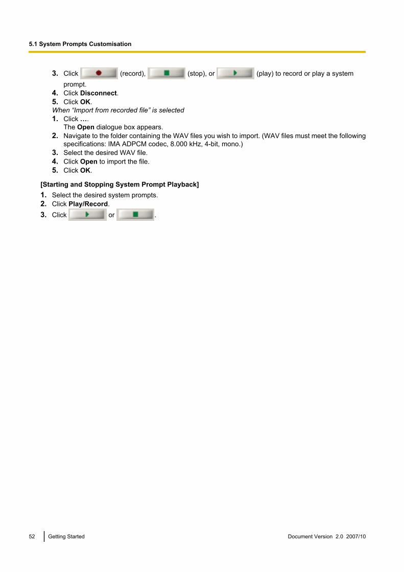
3. Click (record), (stop), or (play) to record or play a systemprompt.
4. Click Disconnect.5. Click OK.When “Import from recorded file” is selected1. Click ….
The Open dialogue box appears.2. Navigate to the folder containing the WAV files you wish to import. (WAV files must meet the following
specifications: IMA ADPCM codec, 8.000 kHz, 4-bit, mono.)3. Select the desired WAV file.4. Click Open to import the file.5. Click OK.
[Starting and Stopping System Prompt Playback]1. Select the desired system prompts.2. Click Play/Record.3. Click or .
52 Getting Started Document Version 2.0 2007/10
5.1 System Prompts Customisation
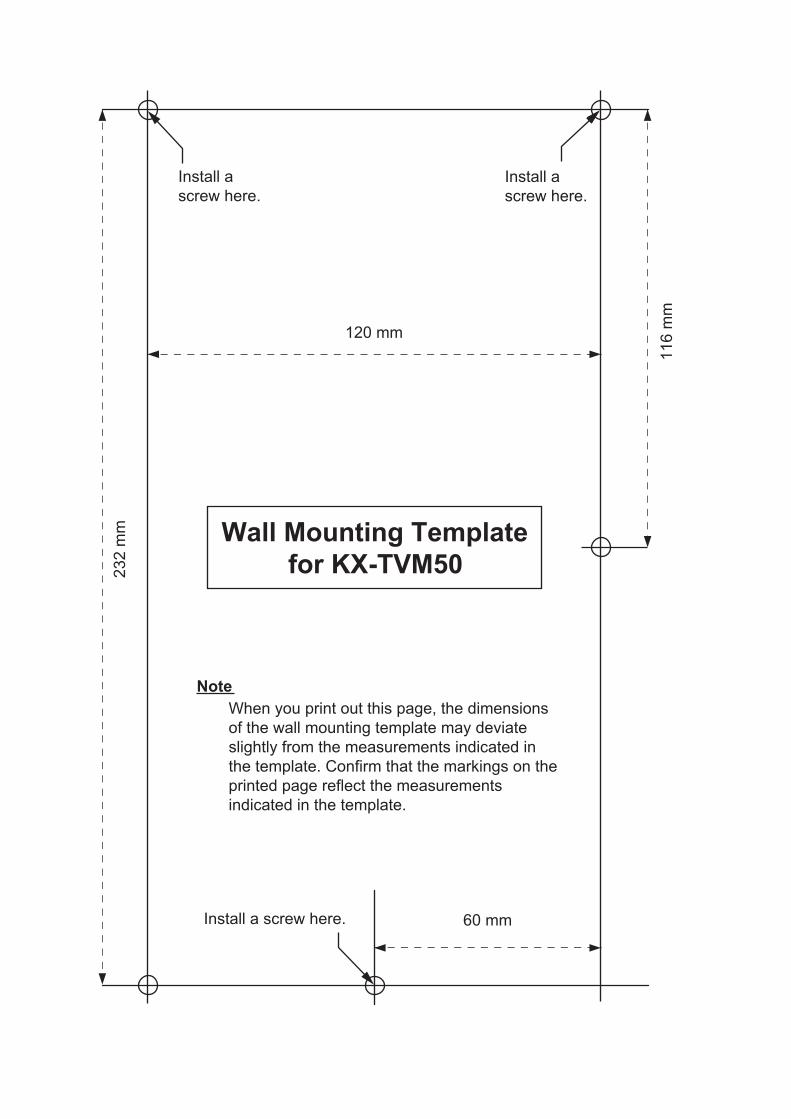
232 m
m
60 mm
120 mm
116 m
m
Install a screw here.
Install a
screw here.
Install a
screw here.
Note
Wall Mounting Template
for KX-TVM50
When you print out this page, the dimensions
of the wall mounting template may deviate
slightly from the measurements indicated in
the template. Confirm that the markings on the
printed page reflect the measurements
indicated in the template.
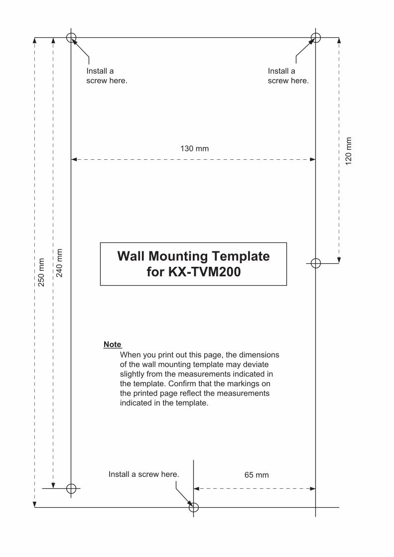
250 m
m
240 m
m
65 mm
130 mm
120 m
m
Install a screw here.
Install a
screw here.
Install a
screw here.
Note
Wall Mounting Template
for KX-TVM200
When you print out this page, the dimensions
of the wall mounting template may deviate
slightly from the measurements indicated in
the template. Confirm that the markings on
the printed page reflect the measurements
indicated in the template.

Document Version 2.0 2007/10 Getting Started 55
Notes

Trademarks• Microsoft, Windows, and Windows Vista are either registered trademarks or trademarks of Microsoft
Corporation in the United States and/or other countries.• Intel and Pentium are trademarks or registered trademarks of Intel Corporation or its subsidiaries in the United
States and other countries.• All other trademarks identified herein are the property of their respective owners.• Screen shots reprinted with permission from Microsoft Corporation.
Panasonic Communications Co., Ltd. declares that the KX-TVM50E/KX-TVM200E and KX-TVM50NE/KX-TVM200NE are in compliance with the essential requirements and other relevant provisions of Radio &Telecommunications Terminal Equipment (R&TTE) Directive 1999/5/EC.Declarations of Conformity for the relevant Panasonic products described in this manual are available for downloadby visiting:
http://doc.panasonic.de
Contact to Authorised Representative:Panasonic Testing CentrePanasonic Marketing Europe GmbHWinsbergring 15, 22525 Hamburg, Germany
Panasonic Communications Co., Ltd.1-62, 4-chome, Minoshima, Hakata-ku, Fukuoka 812-8531, Japan
Copyright:This material is copyrighted by Panasonic Communications Co., Ltd., and may be reproduced for internal use only.All other reproduction, in whole or in part, is prohibited without the written consent of Panasonic CommunicationsCo., Ltd.
© 2005 Panasonic Communications Co., Ltd. All Rights Reserved.
PSQX3225WA KK0205HF3107