vol.11, no.2, pp.229–245, june 2017 doi 10.1007/s40069 … · im et al. (2013) tested five...
TRANSCRIPT
Experimental Cyclic Behavior of Precast Hybrid Beam-ColumnConnections with Welded Components
Sadik Can Girgin*, Ibrahim Serkan Misir, and Serap Kahraman
(Received January 10, 2016, Accepted January 31, 2017, Published online May 22, 2017)
Abstract: Post-earthquake observations revealed that seismic performance of beam-column connections in precast concrete
structures affect the overall response extensively. Seismic design of precast reinforced concrete structures requires improved beam-
column connections to transfer reversed load effects between structural elements. In Turkey, hybrid beam-column connections with
welded components have been applied extensively in precast concrete industry for decades. Beam bottom longitudinal rebars are
welded to beam end plates while top longitudinal rebars are placed to designated gaps in joint panels before casting of topping
concrete in this type of connections. The paper presents the major findings of an experimental test programme including one
monolithic and five precast hybrid half scale specimens representing interior beam-column connections of a moment frame of high
ductility level. The required welding area between beam bottom longitudinal rebars and beam-end plates were calculated based on
welding coefficients considered as a test parameter. It is observed that the maximum strain developed in the beam bottom flexural
reinforcement plays an important role in the overall behavior of the connections. Two additional specimens which include
unbonded lengths on the longitudinal rebars to reduce that strain demands were also tested. Strength, stiffness and energy
dissipation characteristics of test specimens were investigated with respect to test variables. Seismic performances of test speci-
mens were evaluated by obtaining damage indices.
Keywords: beam-column connections, precast concrete, welding, unbonded length, damage index.
1. Introduction
One-story precast concrete structures constitute a signifi-cant part of industrial buildings in earthquake-prone regionsin Turkey. Post-earthquake observations revealed that beam-column connections are widely influence the overall seismicresponse of precast concrete structures (Saatcioglu et al.2001; Ozden and Meydanli 2003; Senel and Palanci 2013).It is still a challenging subject to develop precast concretebeam-column connections emulating the seismic perfor-mance of monolithic systems to maintain advantages ofprecast construction process for multi-story buildings.In the literature, joint is defined as the intersection of beam
and column elements while connection is the region whereprecast elements connectedwith a technique (welding, boltingetc.) during construction. Moment-resisting beam-columnconnections can be categorized mainly as emulative (wet) anddry connections (e.g. ACI 550.2R 2013). In addition, emula-tive and mechanical components can be assembled to consti-tute hybrid beam-column connections (Negro and Toniolo2012) which are commonly used in Turkey.
In emulative connections, continuity of reinforcing bars isprovided by a coupling connector or splicing throughout thedesignated gaps in precast beam and column elements at aprecast construction facility. Precast beams are firstly sup-ported on columns’ cover concrete and then the toppingconcrete is poured on site to fill the gaps in the column andthe top of the beam (Park and Bull 1986; Chen et al. 2012).Im et al. (2013) tested five interior precast beam- columnconnections with U-shaped beam shells. Main test parame-ters were seating length of beam to joint, steel angle forcover concrete and installation of headed rebars. It wasconcluded that increase in effective depth of beam-columnconnection can be obtained by decreasing the seating lengthand the beam shell thickness.Dry beam-column connections are achieved by connecting
the precast elements with post-tensioning, welding orembedded rods. Chang et al. (2013) presented experimentalresults of two full-scale interior beam-column connectionswith embedded ductile rods within the joint region. Main testparameters were the use of high strength concrete, post-tensioning and high performance reinforcing steel. Theywere concluded that specimens sustained large drifts withoutany strength degradation. Experimental studies on post-ten-sioned connections showed that increase in mild reinforce-ment ratio results in improved ductility and energydissipation capacities. However, in some cases prematurebuckling and rupture of mild reinforcement may occurbefore reaching the drift ratios that the connection can
Department of Civil Engineering, Dokuz Eylul
University, 35160 Buca-Izmir, Turkey.
*Corresponding Author; E-mail: [email protected]
Copyright � The Author(s) 2017. This article is an open
access publication
International Journal of Concrete Structures and MaterialsVol.11, No.2, pp.229–245, June 2017DOI 10.1007/s40069-017-0190-yISSN 1976-0485 / eISSN 2234-1315
229

sustain (Cheok et al. 1993; Priestley et al. 1999; ACI T1.22003; Ertas et al. 2006). It is proposed that, unbonding ofreinforcing bars over a length of precast beam and columnelements in a sleeve can reduce the strain demands andprevent rupture which leads significant degradation instrength (Cheok et al. 1996; Pampanin et al. 2001; Belleriet al. 2012). However, unbonded length should be selectedproperly to ensure yielding of reinforcing bars without pre-mature rupture (Cheok et al. 1993).In the third category, hybrid (emulative-welded) connec-
tions are widely used in residential and industrial framestructures where negative moment continuity is madethrough cast-in-place connection while positive momentcontinuity is satisfied through welding. Figure 1 shows afabrication process of a precast structure by applying hybridconnections with the stages from precast facility to site.First, beam longitudinal and transverse rebars are welded tobeam end plates and the remaining rebars in beam elementsare installed (Fig. 1a, b). At the meantime, precast columnswith corbels of hybrid connections are prepared and a gap isdeliberately left at the top of the joint before casting ofconcrete to fill with topping concrete (Fig. 1c). After trans-portation and installation of precast beam, column, and slabelements, continuity between these elements are provided bypouring topping concrete in each floor level (Fig. 1d).Seismic behavior of precast connections is required to be
proved by experimental or numerical studies in terms ofequivalent strength and ductility reflecting the monolithicbehavior as specified in seismic codes (TEC 2007; ACI 3182011). There has been a great deal of research by means of
experimental and numerical studies on reinforced concretebeam-column joints (Ronagh and Baji 2014; Kim andHyunhoon 2015; Kassem 2015; Rashidian et al. 2016; Limet al. 2016). However, there are a limited number ofexperimental studies on the behavior of hybrid (emulative-welded) connections in the literature. Ertas et al. (2006)tested half-scaled one exterior beam-column connectionwhere the first diagonal crack near the connection wasreported at 2.2% drift ratio and the beam bottom rebarsruptured at the first cycle of 3.5% drift ratio. Yuksel et al.(2015) tested five half-scaled exterior hybrid connectionsincluding a slab which are subjected to monotonic and cyclicdrifts applied at the beam tip. Monotonic and cyclic tests onfirst three specimens showed that strength degradationoccurs due to rupture of welded longitudinal rebars andtransverse rebars at the connection. Improved specimensshowed an increased energy dissipation capacity while theobserved in-cycle degradation was about 50% at a drift ratioof 3%. During the tests, increase in strain demands of beamwelded rebars played an important role for overall behaviorsof the connections.Experimental studies on welded ASTM A615 type rein-
forcing bars (ASTM 1992) revealed that welding processcauses heat-affected zone on reinforcements following anembrittlement on the material which is undesirable for aductile seismic design (Rodriguez and Rodriguez 2006;Rodrıguez and Torres-Matos 2013). This kind of rebarsshowed a decreased tensile strain capacity in the vicinity ofthe welded region. However, welding is still a common usedtechnique in connecting the steel parts of structural elements
Fig. 1 A precast structure under construction with hybrid beam-column connections. aWelding of longitudinal beam bottom rebarsto beam end plate. b Installation of flexural and shear reinforcement for a precast beam. c Installation of flexural and shearreinforcements to constitute the precast column and corbels. d Assembling precast beam and column elements on site.
230 | International Journal of Concrete Structures and Materials (Vol.11, No.2, June 2017)

in precast industry. As shown in the latter sections in thisstudy that, rebars with low carbon content (e.g. B420C gradesteel) defined in TS708 code (2010) could show a sufficientductile behavior under tensile forces after a welding process.An experimental research program was carried out to
improve the cyclic behavior of hybrid (emulative-welded)beam-column connections. In this study, half scale onemonolithic and five precast specimens representing interiorbeam-column connections were tested under reversed cyclicloading. Strength, stiffness and energy dissipation capacitiesof test specimens were investigated with respect to weldingcoefficient and unbonded length as the main test variables.Moreover, damage indices were also obtained to comparethe seismic performance of these test specimens.
2. Experimental Study
2.1 Material TestsWeldability and hence the mechanical properties of a
reinforcement after welding depend on the chemical com-position of the material defined as carbon content (C) andcarbon equivalent (CE) ratios (Atakoy 2014; TS 708 2010;ASTM A706M 2013). Therefore, appropriate type of lon-gitudinal rebars which is compatible with the upper limitsspecified by the TS 708 code (2010) (C: 0.22%, CE: 0.50%)were installed to beam and column sections except onespecimen. The rebars were also satisfying the carbon contentand CE allowable limits (C: 0.30%, CE: 0.55%) given inASTM A706M (2013) for Grade 60 rebars which has similarmechanical characteristics.In order to characterize the tensile behavior of the rebars
welded to steel plate representing the rebar-plate connectionsubassembly in the test specimens, tensile test was per-formed on 18 mm diameter reinforcing bars welded from
both sides to PL plate (St 37 steel) as shown in Fig. 2a.Appropriate electrodes (E42 type) were used to weld rebarsto plate providing filler metal requirements due to TS ENISO 2560 (2013). Figure 2b shows the specimen duringtesting while average strains in rebar were determined byusing optical sensors focused on two points located at thevicinity of the plate.Rebar rupture occurred within the unwelded part of the
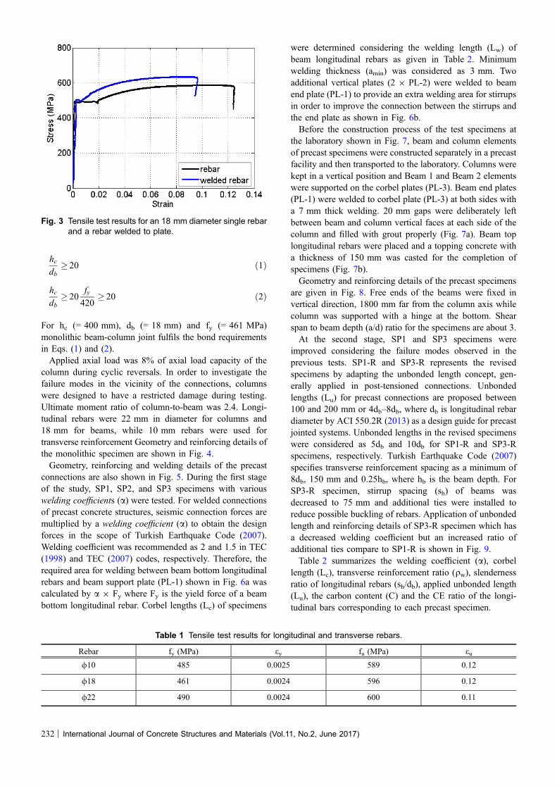
rebar specimen at 9.5% strain with a clear necked regionverifying a ductile behavior under tension as shown inFig. 2c. A tensile test was also performed on single rebar(not welded to plate) where tensile strain at rupture isdetermined as 12%. While interpreting the decrease in ten-sion strain in the case of welded rebar, potential stressconcentrations near the plate and heat-affected zones shouldbe keep in mind. Besides, it is concluded that using propertype of reinforcement didn’t lead to a brittle failure. Thestress–strain curves gathered from the tensile tests for singleand welded rebars are shown in Fig. 3.Tensile test results of longitudinal and transverse rebars
are given in Table 1. Average cylindrical concrete com-pressive strength (fcm) for the monolithic specimen, for beamand column precast elements, and the topping concrete were37, 42, and 35 MPa at the test days.
2.2 Test SpecimensHalf scale test specimens were designed in accordance with
Turkish Earthquake Code (TEC 2007) and ACI 352R (2002)requirements representing an interior connection betweeninflection points of beam and column elements of a four-storyprecast building with moment frames of high ductility level.For interior beam-column joints, bond requirements arespecified by ACI 318 (2011) (Eq. 1) and ACI 352R (2002)(Eq. 2) for column depth-to-beam rebar diameter ratio (hc/db)which are given in the following equations.
Fig. 2 a Schematic view of welded rebar-plate specimen, b specimen during tensile test, and c rupture of rebar with a clear neckedregion.
International Journal of Concrete Structures and Materials (Vol.11, No.2, June 2017) | 231
hcdb
� 20 ð1Þ
hcdb
� 20fy420
� 20 ð2Þ
For hc (= 400 mm), db (= 18 mm) and fy (= 461 MPa)monolithic beam-column joint fulfils the bond requirementsin Eqs. (1) and (2).Applied axial load was 8% of axial load capacity of the
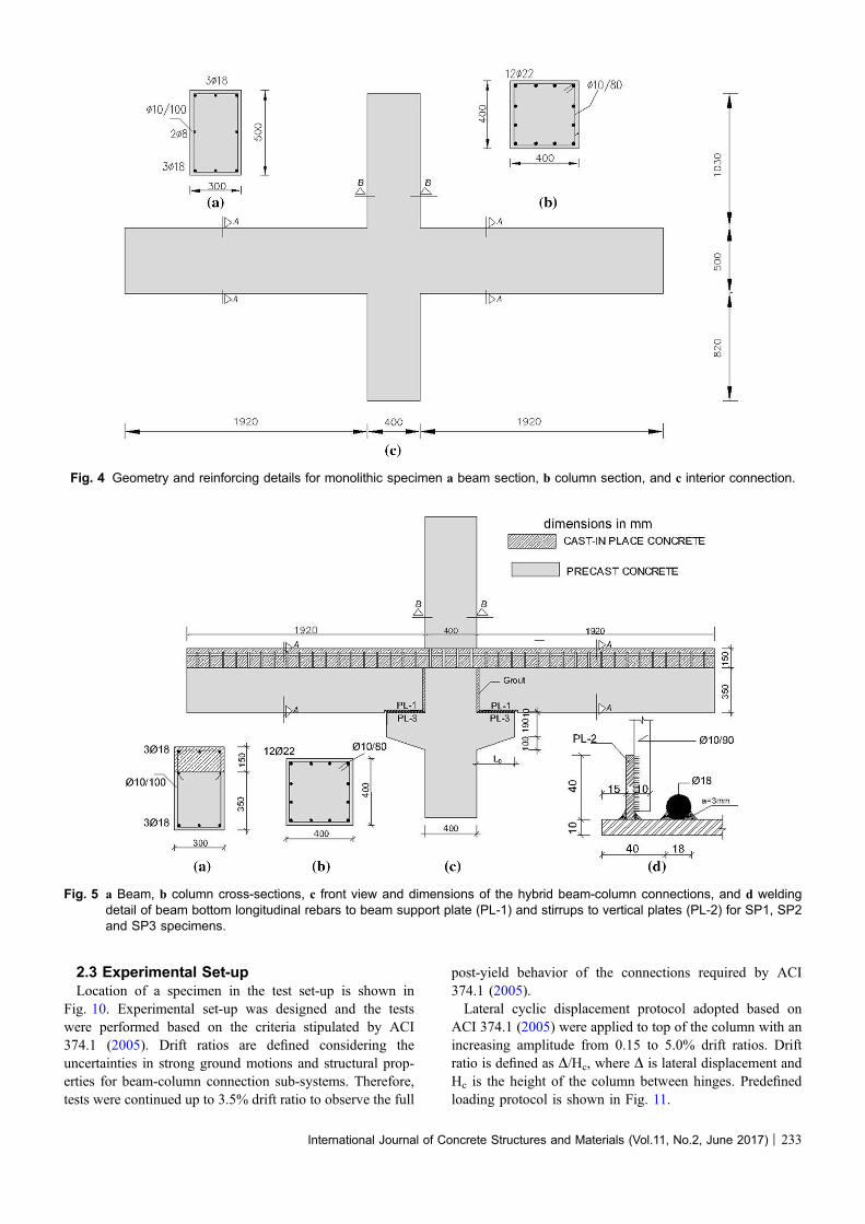
column during cyclic reversals. In order to investigate thefailure modes in the vicinity of the connections, columnswere designed to have a restricted damage during testing.Ultimate moment ratio of column-to-beam was 2.4. Longi-tudinal rebars were 22 mm in diameter for columns and18 mm for beams, while 10 mm rebars were used fortransverse reinforcement Geometry and reinforcing details ofthe monolithic specimen are shown in Fig. 4.Geometry, reinforcing and welding details of the precast
connections are also shown in Fig. 5. During the first stageof the study, SP1, SP2, and SP3 specimens with variouswelding coefficients (a) were tested. For welded connectionsof precast concrete structures, seismic connection forces aremultiplied by a welding coefficient (a) to obtain the designforces in the scope of Turkish Earthquake Code (2007).Welding coefficient was recommended as 2 and 1.5 in TEC(1998) and TEC (2007) codes, respectively. Therefore, therequired area for welding between beam bottom longitudinalrebars and beam support plate (PL-1) shown in Fig. 6a wascalculated by a 9 Fy where Fy is the yield force of a beambottom longitudinal rebar. Corbel lengths (Lc) of specimens
were determined considering the welding length (Lw) ofbeam longitudinal rebars as given in Table 2. Minimumwelding thickness (amin) was considered as 3 mm. Twoadditional vertical plates (2 9 PL-2) were welded to beamend plate (PL-1) to provide an extra welding area for stirrupsin order to improve the connection between the stirrups andthe end plate as shown in Fig. 6b.Before the construction process of the test specimens at
the laboratory shown in Fig. 7, beam and column elementsof precast specimens were constructed separately in a precastfacility and then transported to the laboratory. Columns werekept in a vertical position and Beam 1 and Beam 2 elementswere supported on the corbel plates (PL-3). Beam end plates(PL-1) were welded to corbel plate (PL-3) at both sides witha 7 mm thick welding. 20 mm gaps were deliberately leftbetween beam and column vertical faces at each side of thecolumn and filled with grout properly (Fig. 7a). Beam toplongitudinal rebars were placed and a topping concrete witha thickness of 150 mm was casted for the completion ofspecimens (Fig. 7b).Geometry and reinforcing details of the precast specimens
are given in Fig. 8. Free ends of the beams were fixed invertical direction, 1800 mm far from the column axis whilecolumn was supported with a hinge at the bottom. Shearspan to beam depth (a/d) ratio for the specimens are about 3.At the second stage, SP1 and SP3 specimens were
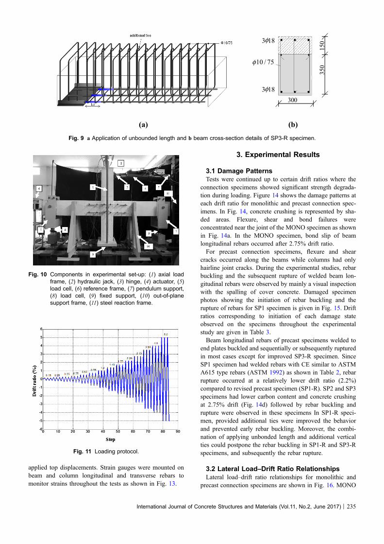
improved considering the failure modes observed in theprevious tests. SP1-R and SP3-R represents the revisedspecimens by adapting the unbonded length concept, gen-erally applied in post-tensioned connections. Unbondedlengths (Lu) for precast connections are proposed between100 and 200 mm or 4db–8db, where db is longitudinal rebardiameter by ACI 550.2R (2013) as a design guide for precastjointed systems. Unbonded lengths in the revised specimenswere considered as 5db and 10db for SP1-R and SP3-Rspecimens, respectively. Turkish Earthquake Code (2007)specifies transverse reinforcement spacing as a minimum of8db, 150 mm and 0.25hb, where hb is the beam depth. ForSP3-R specimen, stirrup spacing (sh) of beams wasdecreased to 75 mm and additional ties were installed toreduce possible buckling of rebars. Application of unbondedlength and reinforcing details of SP3-R specimen which hasa decreased welding coefficient but an increased ratio ofadditional ties compare to SP1-R is shown in Fig. 9.Table 2 summarizes the welding coefficient (a), corbel
length (Lc), transverse reinforcement ratio (qw), slendernessratio of longitudinal rebars (sh/db), applied unbonded length(Lu), the carbon content (C) and the CE ratio of the longi-tudinal bars corresponding to each precast specimen.
Fig. 3 Tensile test results for an 18 mm diameter single rebarand a rebar welded to plate.
Table 1 Tensile test results for longitudinal and transverse rebars.
Rebar fy (MPa) ey fu (MPa) eu
/10 485 0.0025 589 0.12
/18 461 0.0024 596 0.12
/22 490 0.0024 600 0.11
232 | International Journal of Concrete Structures and Materials (Vol.11, No.2, June 2017)
2.3 Experimental Set-upLocation of a specimen in the test set-up is shown in
Fig. 10. Experimental set-up was designed and the testswere performed based on the criteria stipulated by ACI374.1 (2005). Drift ratios are defined considering theuncertainties in strong ground motions and structural prop-erties for beam-column connection sub-systems. Therefore,tests were continued up to 3.5% drift ratio to observe the full
post-yield behavior of the connections required by ACI374.1 (2005).Lateral cyclic displacement protocol adopted based on
ACI 374.1 (2005) were applied to top of the column with anincreasing amplitude from 0.15 to 5.0% drift ratios. Driftratio is defined as D/Hc, where D is lateral displacement andHc is the height of the column between hinges. Predefinedloading protocol is shown in Fig. 11.
Fig. 4 Geometry and reinforcing details for monolithic specimen a beam section, b column section, and c interior connection.
Fig. 5 a Beam, b column cross-sections, c front view and dimensions of the hybrid beam-column connections, and d weldingdetail of beam bottom longitudinal rebars to beam support plate (PL-1) and stirrups to vertical plates (PL-2) for SP1, SP2and SP3 specimens.
International Journal of Concrete Structures and Materials (Vol.11, No.2, June 2017) | 233

In order to monitor deformations, 12 linear variable dis-placement transducers (LVDT) were installed by 300 mmspacing in vertical and horizontal directions. Installation of
LVDT’s are shown in Fig. 12a for MONO, SP1-R, SP3; andin Fig. 12b for SP1, SP2, SP3-R specimens. Also, two stringpots were installed at the top of the column to monitor the
Fig. 6 a Perspective view of beam longitudinal rebars welded to beam support plate (PL-1) and b stirrups welded to additionalvertical plates (2 9 PL-2).
Fig. 7 a Installation process of precast beam-column connection specimens and b casting of topping concrete.
Fig. 8 Geometry and reinforcing details of precast specimens, a beam cross section, b column cross section, and c corbel details.
Table 2 Main test parameters and properties of precast concrete interior connections.
Specimen a Lc (mm) Lw (mm) qw (%) sh/db Lu (mm) C (%) CE (%)
SP1 2.0 450 340 0.52 5.6 N.A. 0.31 0.49
SP2 1.5 350 250 0.52 5.6 N.A 0.19 0.35
SP3 1.2 300 200 0.52 5.6 N.A 0.196 0.37
SP1-R 2.0 450 340 0.52 5.6 5 db 0.19 0.35
SP3-R 1.2 300 200 1.0 4.2 10 db 0.196 0.34
234 | International Journal of Concrete Structures and Materials (Vol.11, No.2, June 2017)
applied top displacements. Strain gauges were mounted onbeam and column longitudinal and transverse rebars tomonitor strains throughout the tests as shown in Fig. 13.
3. Experimental Results
3.1 Damage PatternsTests were continued up to certain drift ratios where the
connection specimens showed significant strength degrada-tion during loading. Figure 14 shows the damage patterns ateach drift ratio for monolithic and precast connection spec-imens. In Fig. 14, concrete crushing is represented by sha-ded areas. Flexure, shear and bond failures wereconcentrated near the joint of the MONO specimen as shownin Fig. 14a. In the MONO specimen, bond slip of beamlongitudinal rebars occurred after 2.75% drift ratio.For precast connection specimens, flexure and shear
cracks occurred along the beams while columns had onlyhairline joint cracks. During the experimental studies, rebarbuckling and the subsequent rupture of welded beam lon-gitudinal rebars were observed by mainly a visual inspectionwith the spalling of cover concrete. Damaged specimenphotos showing the initiation of rebar buckling and therupture of rebars for SP1 specimen is given in Fig. 15. Driftratios corresponding to initiation of each damage stateobserved on the specimens throughout the experimentalstudy are given in Table 3.Beam longitudinal rebars of precast specimens welded to
end plates buckled and sequentially or subsequently rupturedin most cases except for improved SP3-R specimen. SinceSP1 specimen had welded rebars with CE similar to ASTMA615 type rebars (ASTM 1992) as shown in Table 2, rebarrupture occurred at a relatively lower drift ratio (2.2%)compared to revised precast specimen (SP1-R). SP2 and SP3specimens had lower carbon content and concrete crushingat 2.75% drift (Fig. 14d) followed by rebar buckling andrupture were observed in these specimens In SP1-R speci-men, provided additional ties were improved the behaviorand prevented early rebar buckling. Moreover, the combi-nation of applying unbonded length and additional verticalties could postpone the rebar buckling in SP1-R and SP3-Rspecimens, and subsequently the rebar rupture.
3.2 Lateral Load–Drift Ratio RelationshipsLateral load–drift ratio relationships for monolithic and
precast connection specimens are shown in Fig. 16. MONO
3 18
3 18
10 / 75
300
350
150
(b)(a)
φ
φ
φ
Fig. 9 a Application of unbounded length and b beam cross-section details of SP3-R specimen.
Fig. 10 Components in experimental set-up: (1) axial loadframe, (2) hydraulic jack, (3) hinge, (4) actuator, (5)load cell, (6) reference frame, (7) pendulum support,(8) load cell, (9) fixed support, (10) out-of-planesupport frame, (11) steel reaction frame.
Fig. 11 Loading protocol.
International Journal of Concrete Structures and Materials (Vol.11, No.2, June 2017) | 235

specimen attained the maximum strength at 1.75% driftratio. Severe pinching in load–drift relation was observeddue to bond slip of beam longitudinal rebars at 2.75% driftratio as seen in Fig. 16a where bond requirements weresatisfied given by the codes (ACI 352 2002; ACI 318 2011).As the embedment length (equals to column depth) of beamreinforcing bars within the beam-column joint decreases,rebar slip will increase and result in a more pinched hys-teretic plot (Moehle 2014). For precast connections, beambottom longitudinal rebars were welded and only top rebarshave continuity throughout the joint. Embedment lengths oftop rebars could be increased from column depth (hc) to alength with the sum of column depth and corbel lengths(hc ? Lc) which led to an increased energy dissipationcapacity.In SP1 specimen, maximum strength was attained at 2.2%
drift ratio in the pull and push directions as shown inFig. 16b. 40% degradation in strength for SP1 specimen wasobserved due to premature failure of beam welded longitu-dinal rebars. SP2 and SP3 specimens showed similar
behavior and maximum strengths were attained at 2.2% driftratio as shown in Fig. 16c, d.In SP1-R specimen, tests were performed up to 5% and
3.5% drift ratios in push and pull directions as shown inFig. 16e, respectively. SP1-R specimen showed a moreductile behavior compare to SP1 specimen. However, shearfailures after 3.5% drift ratio led severe pinching as can beseen in load–drift relationship. SP3-R specimen attainedmaximum strength at 2.2% drift ratio and first degradation instrength was observed at the second cycle of 3.5 drift ratio asshown in Fig. 16f.
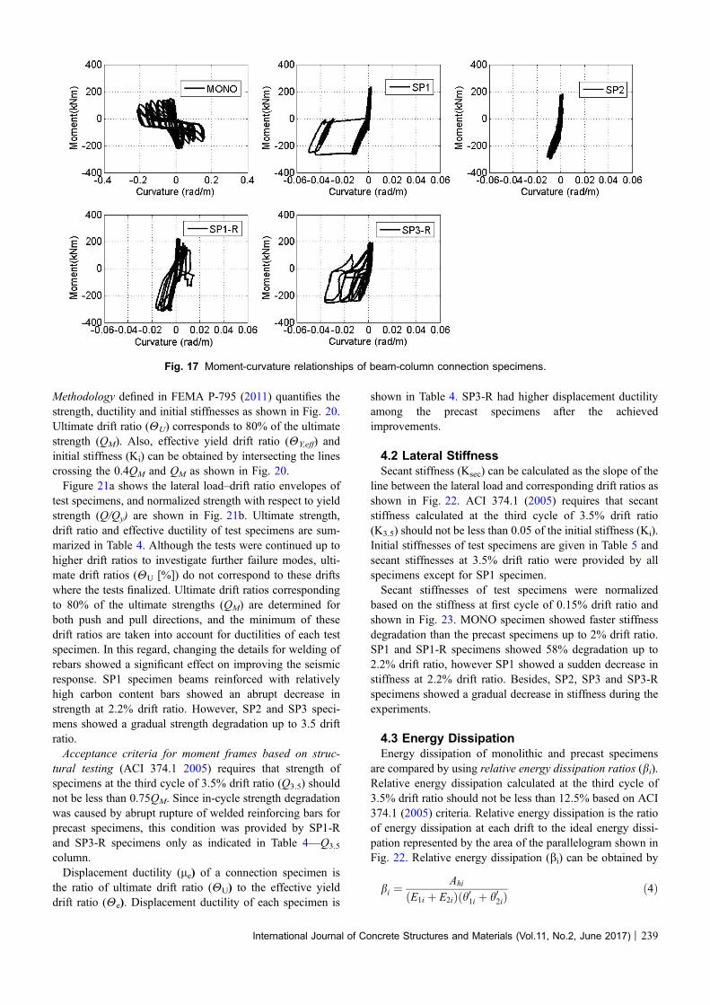
3.3 Local ResponseBeam curvatures, strain in reinforcing bars and shear
deformations were determined for each specimen based onexperimental measurements to obtain local response quan-tities. Beam curvatures in connection specimens were cal-culated based on the data taken from LVDTs (1 and 2)mounted on the connection region which includes beam endsand the joint panel as shown in Fig. 12b. For all specimens,
Fig. 12 Installation of LVDTs for a MONO, SP1-R, SP3 and b SP1, SP2, and SP3-R specimens.
Fig. 13 Installation of strain gauges on beams and column reinforcing bars (units in mm).
236 | International Journal of Concrete Structures and Materials (Vol.11, No.2, June 2017)

Fig. 14 Damage patterns of test specimens at each drift ratio and the end of test. a MONO, b SP1, c SP1-R, d SP3, and e SP3-R.
Fig. 15 a Initiation of rebar buckling at the left beam (Beam 1) and b the rupture of rebars at the right beam (Beam 2) for SP1specimen at 2.2% top drift.
International Journal of Concrete Structures and Materials (Vol.11, No.2, June 2017) | 237

moments were determined for Beam 1 element (Fig. 7a) atthe joint face using the data taken from load cell which isembedded in the pendulum support. Figure 17 showsmoment–curvature relationships for beams of beam-columnconnection specimens.Measured strains of beam and column longitudinal rebars
of all specimens are shown in Fig. 18 where strain gaugelocations are given in Fig. 13. Large plastic strains in thebeam longitudinal rebars were developed in the vicinity ofthe welded connections as shown in Fig. 18a–e. Drift ratiosat which the strain gauge capacities exceeded the strain limitof the gauges are also noted in the figures. In SP1-R andSP3-R specimens, application of unbonded length could beable to increase the number of strain cycles of welded lon-gitudinal rebars as well as plastic deformation capacities. Onthe other hand, column longitudinal rebars remained nearlyelastic during the tests as shown in Fig. 18f–i.Shear deformations of beams (Ds) in the vicinity of con-
nections of SP1, SP2 and SP3-R specimens were calculated
based on the measurements using D1 and D2 transducersshown in Fig. 12b. Shear deformations are calculated as,
Ds ¼ðD2� D1Þ2 sin h
ð3Þ
where h is the inclination angle of diagonal LVDT’s (45�)with respect to horizontal axis with Fig. 19 shows beamshear force–shear deformation relationships. In SP3-Rspecimen which has additional vertical ties and more fre-quent transverse reinforcement, shear deformations in beamelements could be reduced reasonably.
4. Evaluation of Experimental Results
4.1 Lateral Strength and DuctilityLateral load–drift ratio envelopes of test specimens were
obtained by combining the maximum lateral loads corre-sponding to each drift ratio. Component Equivalency
Fig. 16 Lateral load–drift ratio relationships for monolithic and precast connection specimens.
Table 3 Drift ratios corresponding to initiation of each observed damage state.
Specimen Flexural crack (%) Shear crack (%) Diagonal cracks injoint panel (%)
Concrete spalling(%)
Rebar buckling Rebar rupture
MONO 0.25 1.0 1.4 2.75 N.A. N.A.
SP1 0.25 0.5 1.75 2.2 2.2% (2nd cycle) 2.2% (2nd cycle)
SP2 0.35 0.75 1.4 2.2 2.75% 3.5% (2nd cycle)
SP3 0.25 0.75 1.4 2.2 2.75% 3.5% (1st cycle)
SP1-R 0.25 0.75 1.4 2.75 3.5% (1st cycle) 3.5% (3rd cycle)
SP3-R 0.35 1.0 1.4 2.75 N.A. 3.5% (3rd cycle)
238 | International Journal of Concrete Structures and Materials (Vol.11, No.2, June 2017)
Methodology defined in FEMA P-795 (2011) quantifies thestrength, ductility and initial stiffnesses as shown in Fig. 20.Ultimate drift ratio (HU) corresponds to 80% of the ultimatestrength (QM). Also, effective yield drift ratio (HY,eff) andinitial stiffness (Ki) can be obtained by intersecting the linescrossing the 0.4QM and QM as shown in Fig. 20.Figure 21a shows the lateral load–drift ratio envelopes of
test specimens, and normalized strength with respect to yieldstrength (Q/Qy) are shown in Fig. 21b. Ultimate strength,drift ratio and effective ductility of test specimens are sum-marized in Table 4. Although the tests were continued up tohigher drift ratios to investigate further failure modes, ulti-mate drift ratios (HU [%]) do not correspond to these driftswhere the tests finalized. Ultimate drift ratios correspondingto 80% of the ultimate strengths (QM) are determined forboth push and pull directions, and the minimum of thesedrift ratios are taken into account for ductilities of each testspecimen. In this regard, changing the details for welding ofrebars showed a significant effect on improving the seismicresponse. SP1 specimen beams reinforced with relativelyhigh carbon content bars showed an abrupt decrease instrength at 2.2% drift ratio. However, SP2 and SP3 speci-mens showed a gradual strength degradation up to 3.5 driftratio.Acceptance criteria for moment frames based on struc-
tural testing (ACI 374.1 2005) requires that strength ofspecimens at the third cycle of 3.5% drift ratio (Q3.5) shouldnot be less than 0.75QM. Since in-cycle strength degradationwas caused by abrupt rupture of welded reinforcing bars forprecast specimens, this condition was provided by SP1-Rand SP3-R specimens only as indicated in Table 4—Q3.5
column.Displacement ductility (le) of a connection specimen is
the ratio of ultimate drift ratio (HU) to the effective yielddrift ratio (He). Displacement ductility of each specimen is
shown in Table 4. SP3-R had higher displacement ductilityamong the precast specimens after the achievedimprovements.
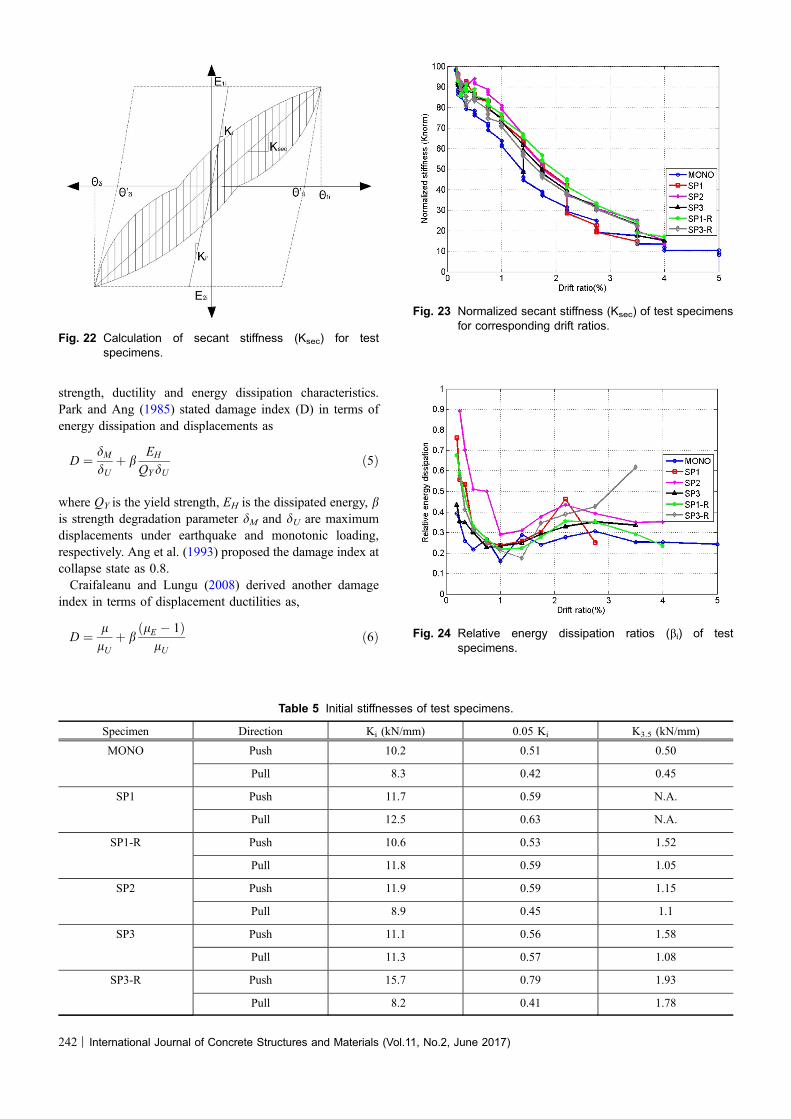
4.2 Lateral StiffnessSecant stiffness (Ksec) can be calculated as the slope of the
line between the lateral load and corresponding drift ratios asshown in Fig. 22. ACI 374.1 (2005) requires that secantstiffness calculated at the third cycle of 3.5% drift ratio(K3.5) should not be less than 0.05 of the initial stiffness (Ki).Initial stiffnesses of test specimens are given in Table 5 andsecant stiffnesses at 3.5% drift ratio were provided by allspecimens except for SP1 specimen.Secant stiffnesses of test specimens were normalized
based on the stiffness at first cycle of 0.15% drift ratio andshown in Fig. 23. MONO specimen showed faster stiffnessdegradation than the precast specimens up to 2% drift ratio.SP1 and SP1-R specimens showed 58% degradation up to2.2% drift ratio, however SP1 showed a sudden decrease instiffness at 2.2% drift ratio. Besides, SP2, SP3 and SP3-Rspecimens showed a gradual decrease in stiffness during theexperiments.
4.3 Energy DissipationEnergy dissipation of monolithic and precast specimens
are compared by using relative energy dissipation ratios (bi).Relative energy dissipation calculated at the third cycle of3.5% drift ratio should not be less than 12.5% based on ACI374.1 (2005) criteria. Relative energy dissipation is the ratioof energy dissipation at each drift to the ideal energy dissi-pation represented by the area of the parallelogram shown inFig. 22. Relative energy dissipation (bi) can be obtained by
bi ¼Ahi
ðE1i þ E2iÞðh01i þ h02iÞð4Þ
Fig. 17 Moment-curvature relationships of beam-column connection specimens.
International Journal of Concrete Structures and Materials (Vol.11, No.2, June 2017) | 239
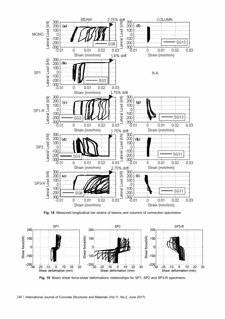
Fig. 18 Measured longitudinal bar strains of beams and columns of connection specimens.
Fig. 19 Beam shear force-shear deformations relationships for SP1, SP2 and SP3-R specimens.
240 | International Journal of Concrete Structures and Materials (Vol.11, No.2, June 2017)

where Ah,i is the area of the closed loop of ith drift ratio, E1i
and E2i are the strengths and h1i and h2i are inelastic driftratios in both loading directions.Figure 24 shows the relative energy dissipation relation-
ship of test specimens corresponding to third cycle of eachdrift ratio. bi values showed a decrease up to 1% drift ratioinherently because of the minor cracks in the test specimens.However, yielding of reinforcement and other failuremechanisms caused an increase in the ratios. All specimensfulfilled the relative energy dissipation criteria mentionedabove.
4.4 Damage IndexDamage index enables seismic evaluation of existing
reinforced concrete buildings subjected to earthquakes.Damage indices of test specimens were calculated based on
Fig. 20 Quantification of strength and ductility of testspecimens.
Fig. 21 a Lateral load–drift ratio envelopes of test specimens and b normalized envelopes of test specimens.
Table 4 Lateral strength and ductility of test specimens.
Specimen Direction QM (kN) 0.75 QM (kN) Q3.5 (kN) HY,eff (%) HU (%) le
MONO Push 189.3 142.0 175.5 0.8 4.0 5.0
Pull 183.8 137.9 144.8 0.96 3.5 3.7
SP1 Push 231.6 173.7 140.3 0.86 3.3 3.8
Pull 287.8 215.9 N.A. 1.0 2.5 2.5
SP1-R Push 263.2 197.4 210.6 1.1 5.0 4.5
Pull 256.9 192.7 130.6 0.96 3.5 3.6
SP2 Push 249.5 187.1 179.1 0.91 3.7 4.1
Pull 237.5 178.1 161.7 1.16 3.9 3.4
SP3 Push 231.2 173.4 168 0.9 3.9 4.3
Pull 235.8 176.9 154.5 0.9 3.7 4.1
SP3-R Push 225.7 169.3 125.7 0.7 3.5 5.1
Pull 228.2 171.1 173.2 1.0 3.5 3.5
International Journal of Concrete Structures and Materials (Vol.11, No.2, June 2017) | 241
strength, ductility and energy dissipation characteristics.Park and Ang (1985) stated damage index (D) in terms ofenergy dissipation and displacements as
D ¼ dMdU
þ bEH
QYdUð5Þ
where QY is the yield strength, EH is the dissipated energy, bis strength degradation parameter dM and dU are maximumdisplacements under earthquake and monotonic loading,respectively. Ang et al. (1993) proposed the damage index atcollapse state as 0.8.Craifaleanu and Lungu (2008) derived another damage
index in terms of displacement ductilities as,
D ¼ llU
þ bðlE � 1Þ
lUð6Þ
Fig. 22 Calculation of secant stiffness (Ksec) for testspecimens.
Table 5 Initial stiffnesses of test specimens.
Specimen Direction Ki (kN/mm) 0.05 Ki K3.5 (kN/mm)
MONO Push 10.2 0.51 0.50
Pull 8.3 0.42 0.45
SP1 Push 11.7 0.59 N.A.
Pull 12.5 0.63 N.A.
SP1-R Push 10.6 0.53 1.52
Pull 11.8 0.59 1.05
SP2 Push 11.9 0.59 1.15
Pull 8.9 0.45 1.1
SP3 Push 11.1 0.56 1.58
Pull 11.3 0.57 1.08
SP3-R Push 15.7 0.79 1.93
Pull 8.2 0.41 1.78
Fig. 23 Normalized secant stiffness (Ksec) of test specimensfor corresponding drift ratios.
Fig. 24 Relative energy dissipation ratios (bi) of testspecimens.
242 | International Journal of Concrete Structures and Materials (Vol.11, No.2, June 2017)
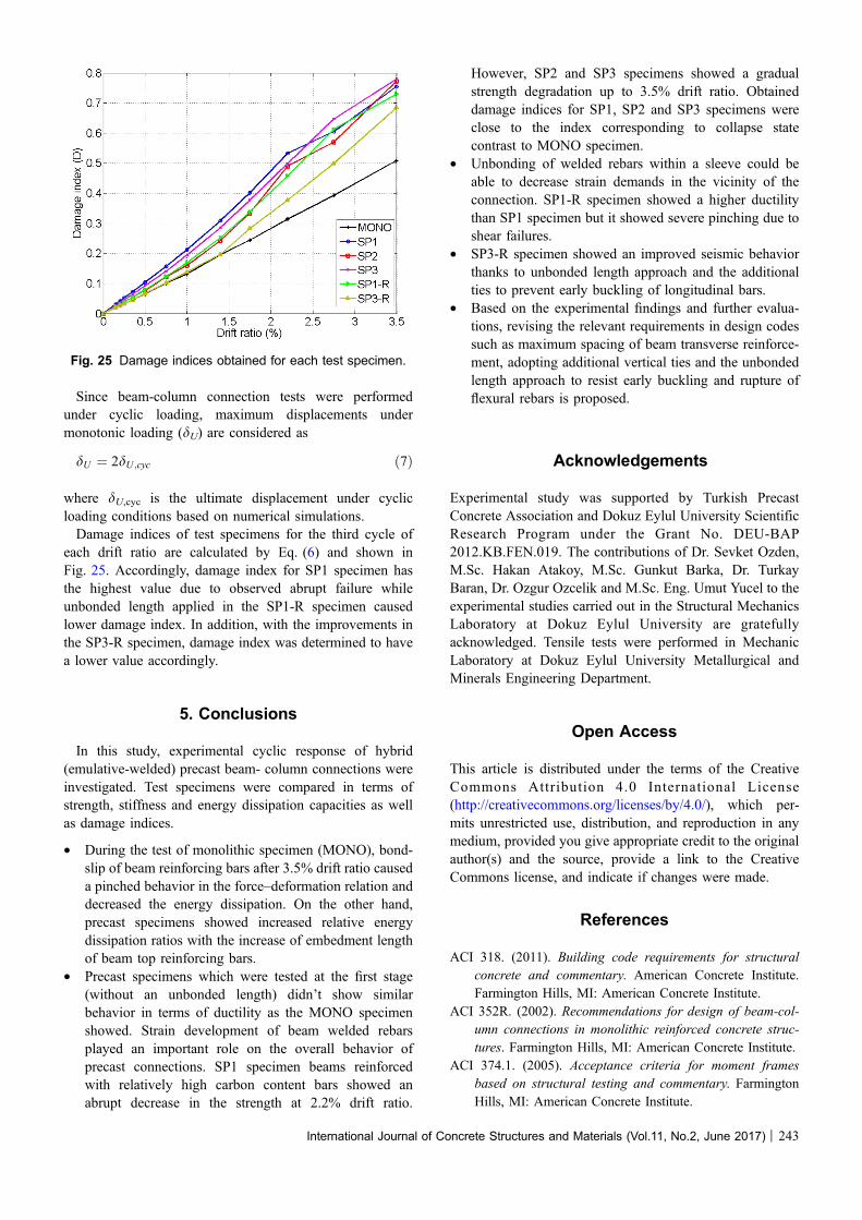
Since beam-column connection tests were performedunder cyclic loading, maximum displacements undermonotonic loading (dU) are considered as
dU ¼ 2dU ;cyc ð7Þ
where dU,cyc is the ultimate displacement under cyclicloading conditions based on numerical simulations.Damage indices of test specimens for the third cycle of
each drift ratio are calculated by Eq. (6) and shown inFig. 25. Accordingly, damage index for SP1 specimen hasthe highest value due to observed abrupt failure whileunbonded length applied in the SP1-R specimen causedlower damage index. In addition, with the improvements inthe SP3-R specimen, damage index was determined to havea lower value accordingly.
5. Conclusions
In this study, experimental cyclic response of hybrid(emulative-welded) precast beam- column connections wereinvestigated. Test specimens were compared in terms ofstrength, stiffness and energy dissipation capacities as wellas damage indices.
• During the test of monolithic specimen (MONO), bond-slip of beam reinforcing bars after 3.5% drift ratio causeda pinched behavior in the force–deformation relation anddecreased the energy dissipation. On the other hand,precast specimens showed increased relative energydissipation ratios with the increase of embedment lengthof beam top reinforcing bars.
• Precast specimens which were tested at the first stage(without an unbonded length) didn’t show similarbehavior in terms of ductility as the MONO specimenshowed. Strain development of beam welded rebarsplayed an important role on the overall behavior ofprecast connections. SP1 specimen beams reinforcedwith relatively high carbon content bars showed anabrupt decrease in the strength at 2.2% drift ratio.
However, SP2 and SP3 specimens showed a gradualstrength degradation up to 3.5% drift ratio. Obtaineddamage indices for SP1, SP2 and SP3 specimens wereclose to the index corresponding to collapse statecontrast to MONO specimen.
• Unbonding of welded rebars within a sleeve could beable to decrease strain demands in the vicinity of theconnection. SP1-R specimen showed a higher ductilitythan SP1 specimen but it showed severe pinching due toshear failures.
• SP3-R specimen showed an improved seismic behaviorthanks to unbonded length approach and the additionalties to prevent early buckling of longitudinal bars.
• Based on the experimental findings and further evalua-tions, revising the relevant requirements in design codessuch as maximum spacing of beam transverse reinforce-ment, adopting additional vertical ties and the unbondedlength approach to resist early buckling and rupture offlexural rebars is proposed.
Acknowledgements
Experimental study was supported by Turkish PrecastConcrete Association and Dokuz Eylul University ScientificResearch Program under the Grant No. DEU-BAP2012.KB.FEN.019. The contributions of Dr. Sevket Ozden,M.Sc. Hakan Atakoy, M.Sc. Gunkut Barka, Dr. TurkayBaran, Dr. Ozgur Ozcelik and M.Sc. Eng. Umut Yucel to theexperimental studies carried out in the Structural MechanicsLaboratory at Dokuz Eylul University are gratefullyacknowledged. Tensile tests were performed in MechanicLaboratory at Dokuz Eylul University Metallurgical andMinerals Engineering Department.
Open Access
This article is distributed under the terms of the CreativeCommons Attribution 4.0 International License(http://creativecommons.org/licenses/by/4.0/), which per-mits unrestricted use, distribution, and reproduction in anymedium, provided you give appropriate credit to the originalauthor(s) and the source, provide a link to the CreativeCommons license, and indicate if changes were made.
References
ACI 318. (2011). Building code requirements for structural
concrete and commentary. American Concrete Institute.
Farmington Hills, MI: American Concrete Institute.
ACI 352R. (2002). Recommendations for design of beam-col-
umn connections in monolithic reinforced concrete struc-
tures. Farmington Hills, MI: American Concrete Institute.
ACI 374.1. (2005). Acceptance criteria for moment frames
based on structural testing and commentary. Farmington
Hills, MI: American Concrete Institute.
Fig. 25 Damage indices obtained for each test specimen.
International Journal of Concrete Structures and Materials (Vol.11, No.2, June 2017) | 243
ACI 550.2R. (2013). Design guide for connections in precast
jointed systems. Farmington Hills, MI: American Concrete
Institute.
ACI ITG/T1.2. (2003). Special hybrid moment frames com-
posed of discretely jointed precast and post-tensioned
concrete member and commentary. Farmington Hills, MI:
American Concrete Institute.
Ang, A. H. S., Kim, W. J., & Kim, S. B. (1993). Damage
estimation of existing bridge structures. In Structural
engineering in natural hazards mitigation: Proceedings of
ASCE structures congress, Irvine CA (Vol. 2,
pp. 1137–1142).
ASTM A615/A 615M. (1992). Deformed and plain billet-steel
bars for concrete reinforcement. West Conshohocken, PA:
ASTM International.
ASTM A706M. (2013). Standard specification for low-alloy
steel deformed and plain bars for concrete reinforcement.
West Conshohocken, PA: ASTM International.
Atakoy, H. (2014). Review on weldability of reinforcing steel,
and design criterion for reinforced concrete applications.
Precast Concrete Journal, 110, 5–9. (in Turkish).
Belleri, A., & Riva, P. (2012). Seismic performance and retrofit
of precast concrete grouted sleeve connections. PCI Jour-
nal, 57(1), 97–109.
Chang, B., Hutchinson, T., Wang, X., & Englekirk, R. (2013).
Experimental seismic performance of beam-column sub-
assemblies using ductile embeds. Journal of Structural
Engineering, 139(9), 1555–1566.
Chen, S., Yan, W., & Gao, J. (2012). Experimental investigation
on the seismic performance of large-scale interior beam-
column joints with composite slab. Advances in Structural
Engineering, 15(7), 1227–1237.
Cheok, G. S., Stone, W. C., & Lew, H. S. (1993). Performance of
1/3-scale model precast concrete beam-column connections
subjected to cyclic inelastic loads. Report No. 3, NISTIR
5246, National Institute of Standard and Technology.
Cheok, G. S., Stone, W. C., & Nakaki, S. D. (1996). Simplified
design procedure for hybrid precast concrete connections.
NISTIR 5765, National Institute of Standard and
Technology.
Craifaleanu, I-G., & Lungu, D. (2008). An assessment of
damage potential and of building performance demands for
Romanian Vrancea earthquakes. In 14th World Conference
on Earthquake Engineering, Beijing, China.
Ertas, O., Ozden, S., & Ozturan, S. (2006). Ductile connections
in precast concrete moment resisting frames. PCI Journal,
51(3), 66–76.
FEMA P-795. (2011). Quantification of building seismic per-
formance factors: Component equivalency methodology.
Washington, DC: Federal Emergency Management Agency.
Im, H., Park, H., & Eom, T. (2013). Cyclic loading test for
reinforced-concrete emulated beam-column connection of
precast concrete moment frame. ACI Structural Journal,
110(1), 115–125.
Kassem, W. (2015). Strength prediction of corbels using strut-
and-tie model analysis. International Journal of Concrete
Structures and Materials, 9(2), 255–266.
Kim, J., & Hyunhoon, C. (2015). Monotonic loading tests of
RC beam-column subassemblage strengthened to prevent
progressive collapse. International Journal of Concrete
Structures and Materials, 9(4), 401–413.
Lim, K., Shin, H., Kim, D., Yoon, Y., & Lee, J. (2016).
Numerical assessment of reinforcing details in beam-col-
umn joints on blast resistance. International Journal of
Concrete Structures and Materials, 10(3), 87–96.
Moehle, J. (2014). Seismic design of reinforced concrete
buildings. New York: McGraw Hill Professional.
Negro, P., & Toniolo. G. (2012). Design guidelines for con-
nections of precast structures under seismic actions. Report
EUR 25377 EN, European Commission.
Ozden, S., & Meydanli, H. (2003). Seismic response of precast
industrial buildings during 1999 Kocaeli earthquake. SE-
40EEE, Skopje earthquake 40 years of European earth-
quake engineering, Skopje, Macedonia.
Pampanin, S., Priestley, M. J., & Sritharan, S. (2001). Analyt-
ical modeling of the seismic behaviour of precast concrete
frames designed with ductile connections. Journal of
Earthquake Engineering, 5(3), 239–367.
Park, R., & Ang, A. H. S. (1985). Mechanistic seismic damage
model for reinforced concrete. Journal of Structural
Engineering, 111(4), 722–739.
Park, R., & Bull, D. K. (1986). Seismic resistance of frames
incorporating precast prestressed concrete beam shells. PCI
Journal, 31(4), 54–93.
Priestley, M. J. N., Sritharan, S., Conley, J. R., & Pampanin, S.
(1999). Preliminary results and conclusions from the
PRESSS five-story precast concrete test building. PCI
Journal, 44(6), 42–67.
Rashidian, O., Abbasnia, R., Ahmadi, R., & Nav, F. M. (2016).
Progressive collapse of exterior reinforced concrete beam–
column sub-assemblages: Considering the effects of a
transverse frame. International Journal of Concrete Struc-
tures and Materials, 10(4), 479–497.
Rodriguez, M. E., & Rodriguez, A. (2006). Welding of rein-
forcing bars should be avoided in reinforced concrete
structures in seismic zones in Mexico. Revista de Inge-
nieria Sismica, Sociedad Mexicana de Ingenieria Sismica,
75, 69–95. (in Spanish).
Rodrıguez, Mario. E., & Torres-Matos, Miguel. (2013). Seismic
behavior of a type of welded precast concrete beam-column
connection. PCI Journal, 58(3), 81–94.
Ronagh, H. R., & Baji, H. (2014). On the FE modeling of FRP-
retrofitted beam–column subassemblies. International
Journal of Concrete Structures and Materials, 8(2),
141–155.
Saatcioglu, M., Mitchell, D., Tinawi, R., Gardner, N. J., Gillies,
A. G., Ghobarah, A., et al. (2001). The August 17, 1999
Kocaeli (Turkey) earthquake-damage to structures. Cana-
dian Journal of Civil Engineering, 28(4), 715–737.
Senel, S., & Palanci, M. (2013). Structural aspects and seismic
performance of 1-story precast buildings in Turkey. Journal
of Performance of Constructed Facilities, 27(4), 437–449.
TS EN ISO 2560. (2013). Welding consumables - Covered
electrodes for manual metal arc welding of non-alloy and
244 | International Journal of Concrete Structures and Materials (Vol.11, No.2, June 2017)
fine grain steels - Classification. Ankara: Turkish Standards
Institution.
TS 708. (2010). Steel for the reinforcement of concrete—Re-
inforcing steel. Ankara: Turkısh Standards Institution.
Turkish Earthquake Code (TEC). (1998). Specifications for
structures built in disaster areas. Ankara: Ministry of
Public Works and Settlement.
Turkish Earthquake Code (TEC). (2007). Specifications for
buildings constructed in disaster areas. Ankara: Ministry
of Public Works and Settlement.
Yuksel, E., Karadogan, H. F., Bal, I. E., Ilki, A., Bal, A., & Inci,
P. (2015). Seismic behavior of two exterior beam-column
connections made of normal-strength concrete developed for
precast construction. Engineering Structures, 99, 157–172.
International Journal of Concrete Structures and Materials (Vol.11, No.2, June 2017) | 245