volt-pac variable autotransformer product features · automatic voltage regulators ... • single...
TRANSCRIPT

Table of ContentsPRODUCT OVERVIEW ................................................................................ 1
GENERAL PERFORMANCE INFORMATION ............................................... 2
MANUAL, SINGLE-PHASE UNITS ............................................................... 4
MANUAL, THREE-PHASE UNITS ................................................................ 5
MOTORIZED, SINGLE-PHASE UNITS ......................................................... 6
MOTORIZED, THREE-PHASE UNITS .......................................................... 7
TERMINAL ARRANGEMENTS, CONNECTIONS AND WIRING ..................... 8
TERMINAL COVER KITS / MOTOR OPERATING TIMES ............................ 9
AUTOMATIC VOLTAGE REGULATORS ......................................................... 10
CONTROLLER ............................................................................................. 12
DIMENSIONS .............................................................................................. 13
CALL US FOR MORE INFORMATION ATVOICE 440-238-2550 FAX 440-238-0660.
E-mail: [email protected]
CROSS REFERENCE TO MOST POPULAR COMPETITORS PRODUCTS
OCATS ROIREPUS RELHCSEW
B-1221050101
C0112
UC611
1A29T99A29T99A29T9
020101510251
U612U621U622
31A29T982A29T903A29T9
0105020501060206
--------------------
UD6511UD6521----------UD6921
U641U642
94A29T915A29T905A29T925A29T983A29T904A29T9
• 99% Efficiency.• + 1% Output accuracy.• No distortion or harmonics.• Single & 3 phase, 120-480V models.• 1.5 Through 500 KVA sizes.• Analog or digital control.• Single or three line control.• Insensitive to Load power factor.
• Single and poly phase models.• Manual and motor driven models.• Programmable digital control option.• Open or enclosed construction.• 99% Efficiency.• 2.5 to 300 Amp capacity.• 120, 240 & 480V models.• Formerly manufactured by GE.
WARRANTY: All Weschler In-struments products are warrantedagainst material defects and work-manship for a period of one (1) yearfrom date of manufacture.
OPTIONS AND FEATURES MAYVARY BETWEEN MODELS, CON-TACT FACTORY FOR SPECIFICS.IN A CONSTANT EFFORT TO IM-PROVE OUR PRODUCTS, SPECI-FICATIONS MAY CHANGE FROMTHOSE PUBLISHED.
Product FeaturesVoltage Regulators Variable Transformers
Volt-Pac Variable Autotransformer

1
The Volt-Pac variable transformer pro-vides continuously adjustable voltage overa range of zero to either 100% or 117% ofthe line voltage. Its operation is simple andefficient, and is based on autotransformeraction.
The Volt-Pac coils are precision woundon a toroidally-shaped core. One face ofthe winding is properly smoothed and goldplated to provide a low resistance and longwearing track for the carbon brush. This plat-ing process has been developed to pro-vide efficient mating of brush and brush trackfor improved reliability of operation undersevere operating conditions. Operating lifehas been substantially improved as a re-sult. The core consists of strip-wound sili-con steel for low electrical losses. The coilis insulated from the core by means of amolded phenolic form.
To aid in heat dissipation a thermal radia-tor is mounted to, but electrically insulatedfrom the shaft. This thermal radiator alsoserves as a brush holder.
DESCRIPTIONManual and motor-operated Volt-Pac
models are listed in this publication. Manualunits provide fingertip voltage control whenthe Volt-Pac is easily accessible; use themotor-operated type for remote and auto-matic control or for large power ratings in-convenient to operate by hand. Roundingout the complete Volt-Pac line, automaticVolt-Pac models can be furnished to pro-vide closely regulated output voltages.
Manual and motorized Volt-Pacs can befurnished in either uncased or cased con-struction. Cased 50, 60 and 75 frame singleand multi-coil units are supplied with termi-nals exposed. Terminial enclosure kits listedon page 9 may be purchased separately.Cased 85 and 95 frame units are suppliedfully enclosed in a NEMA 1 rated enclo-sure. The general configuration of Volt-Pacmodels will vary depending upon the num-ber of cores and how they are stacked to-gether to achieve different ratings.
UL-recognized insulation systems havebeen used throughout. In addition, UL com-ponent listings are applicable to many ofthe models identified on the followingpages.
NO WAVEFORM DISTORTIONVolt-Pac variable transformers provide an
output voltage waveform that is a precisereproduction of the applied input waveform.
1 - New unique plating process on brushtracks results in long life operation. Thisultra reliable feature is now furnishedon all models.
2 - Output voltage selector.3 - Standard steel shaft is easy to replace
or modify.4 - Aluminum radiator dissipates heat, pro-
tects brush track.5 - Self-lubricating nylon bearings for
smooth, reliable rotation.
6 - Cast-aluminum base for maximum heatdissipation provides easy surface orback-of-panel mounting.
7 - Insulation between core-and-coil andmetallic base.
8 - Precision bank-wound coils.9 - Spring-loaded solid-carbon brush.10- Dial plate fits on shaft and provides ref-
erence for voltage selection.11- Corrosion-resistant parts used throughout.
MILLION OPERATION TEST PROVIDESRELIABILITY
With a minimum of moving parts, Volt-Pacvariable transformers are virtually mainte-nance-free. At the point of critical contact,where the carbon brush travels on the coilsurface, extra reliability is built in to assurelong-life operation.
Starting with precision wound coils(wound under constant tension) a smoothsurface is provided for the brush track. Criti-cal tolerances are maintained during thisprocess, a 0.001 in. error results in a reject!On the track area, epoxy cement is added.The coil is then oven-cured. Results are,each length of wire is immobilized, lockedfirmly in position to provide rigid perma-nence and electrical reliability.
Then the brush track is smoothed to a gem-like finish on a lapping machine. This lap-ping process exposes the surface of each
copper conductor to a prescribed depth, re-sulting in a uniformly flat, polished area onwhich the carbon brush travels.
The polished surface is thoroughlycleaned prior to plating to assure maximum"take" of the gold alloy plating process. Goldalloy is used to provide a low resistance,nonoxidizing surface which prevents over-heating and associated burnout problems.
Over this durable, ultra-smooth surface,rides a spring-loaded, grain-oriented solidcarbon brush. The contact between surfacesis so precise that laboratory tests show overone-million operations result in brush wearof less than 0.01 in.
When you specify Volt-Pac variable trans-formers, you're getting precision equipmentdesigned for maximum life with minimummaintenance.
APPLICATIONVolt-Pacs are presently at work onmany electronic and electricalapplications including:
• Power supplies• Laboratory instruments• Test equipment• Speed control devices• Computer peripheral equipment• Welding controls• High-voltage precipitators• Variable speed devices for large machinery• Electroplating• High-voltage electronic tube circuits
Cut-a-way view of 60-frame Volt-Pacvariable transformer.
PRODUCT OVERVIEW
1
2
3
4
5
6
7
8
9
10
Many other types of voltage control devices(such as phase-control semiconductors andsaturable reactors) introduce distortion ofthe voltage waveform. For detailed appli-
Volt-Pac Variable Autotransformer
cation information regarding waveform char-acteristics and Volt-Pac transformers, seethe "waveform distortion" discussion onpage 2.
2
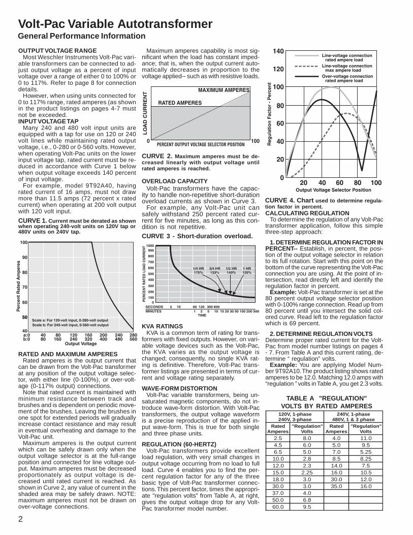
CURVE 4. Chart used to determine regula-tion factor in percent.
CURVE 3 - Short-duration overload.
RATED AND MAXIMUM AMPERESRated amperes is the output current that
can be drawn from the Volt-Pac transformerat any position of the output voltage selec-tor, with either line (0-100%), or over-volt-age (0-117% output) connections.
Note that rated current is maintained withminimum resistance between track andbrushes and is dependent on periodic move-ment of the brushes. Leaving the brushes inone spot for extended periods will graduallyincrease contact resistance and may resultin eventual overheating and damage to theVolt-Pac unit.
Maximum amperes is the output currentwhich can be safely drawn only when theoutput voltage selector is at the full-rangeposition and connected for line voltage out-put. Maximum amperes must be decreasedproportionately as output voltage is de-creased until rated current is reached. Asshown in Curve 2, any value of current in theshaded area may be safely drawn. NOTE:maximum amperes must not be drawn onover-voltage connections.
CURVE 2. Maximum amperes must be de-creased linearly with output voltage untilrated amperes is reached.
KVA RATINGSKVA is a common term of rating for trans-
formers with fixed outputs. However, on vari-able voltage devices such as the Volt-Pac,the KVA varies as the output voltage ischanged; consequently, no single KVA rat-ing is definitive. Therefore, Volt-Pac trans-former listings are presented in terms of cur-rent and voltage rating separately.
WAVE-FORM DISTORTIONVolt-Pac variable transformers, being un-
saturated magnetic components, do not in-troduce wave-form distortion. With Volt-Pactransformers, the output voltage waveformis a precise reproduction of the applied in-put wave-form. This is true for both singleand three phase units.
REGULATION (60-HERTZ)Volt-Pac transformers provide excellent
load regulation, with very small changes inoutput voltage occurring from no load to fullload. Curve 4 enables you to find the per-cent regulation factor for any of the threebasic type of Volt-Pac transformer connec-tions. This percent factor, times the appropri-ate "regulation volts” from Table A, at right,gives the output voltage drop for any Volt-Pac transformer model number.
CALCULATING REGULATIONTo determine the regulation of any Volt-Pac
transformer application, follow this simplethree-step approach:
1. DETERMINE REGULATION FACTOR INPERCENT-- Establish, in percent, the posi-tion of the output voltage selector in relationto its full rotation. Start with this point on thebottom of the curve representing the Volt-Pacconnection you are using. At the point of in-tersection, read directly left and identify theregulation factor in percent.
Example: Volt-Pac transformer is set at the80 percent output voltage selector positionwith 0-100% range connection. Read up from80 percent until you intersect the solid col-ored curve. Read left to the regulation factorwhich is 69 percent.
2. DETERMINE REGULATION VOLTSDetermine proper rated current for the Volt-Pac from model number listings on pages 4- 7. From Table A and this current rating, de-termine “ regulation” volts.
Example: You are applying Model Num-ber 9T92A10. The product listing shows ratedamperes to be 12.0. Matching 12.0 amps with“regulation ” volts in Table A, you get 2.3 volts.
TABLE A "REGULATION"VOLTS BY RATED AMPERES
esahp-1,V021esahp-3,V042
esahp-1,V042esahp3&1,V084
detaRserepmA
"noitalugeR"stloV
detaRserepmA
"noitalugeR"stloV
5.2 0.8 0.4 0.115.4 0.6 0.5 5.95.6 0.5 0.7 52.50.01 8.2 5.8 52.80.21 3.2 0.41 5.70.51 52.2 0.61 5.010.81 0.3 0.03 0.210.03 0.3 0.53 0.610.73 0.40.05 8.60.06 5.9
CURVE 1. Current must be derated as shownwhen operating 240-volt units on 120V tap or480V units on 240V tap.
OVERLOAD CAPACITYVolt-Pac transformers have the capac-
ity to handle non-repetitive short-durationoverload currents as shown in Curve 3.
For example, any Volt-Pac unit cansafely withstand 250 percent rated cur-rent for five minutes, as long as this con-dition is not repetitive.
OUTPUT VOLTAGE RANGEMost Weschler Instruments Volt-Pac vari-
able transformers can be connected to ad-just output voltage as a percent of inputvoltage over a range of either 0 to 100% or0 to 117%. Refer to page 8 for connectiondetails.
However, when using units connected for0 to 117% range, rated amperes (as shownin the product listings on pages 4-7 mustnot be exceeded.INPUT VOLTAGE TAP
Many 240 and 480 volt input units areequipped with a tap for use on 120 or 240volt lines while maintaining rated outputvoltage, i.e., 0-280 or 0-560 volts. However,when operating Volt-Pac units on the lowerinput voltage tap, rated current must be re-duced in accordance with Curve 1 belowwhen output voltage exceeds 140 percentof input voltage.
For example, model 9T92A40, havingrated current of 16 amps, must not drawmore than 11.5 amps (72 percent x ratedcurrent) when operating at 200 volt outputwith 120 volt input.
Maximum amperes capability is most sig-nificant when the load has constant imped-ance; that is, when the output current auto-matically decreases in proportion to thevoltage applied-- such as with resistive loads.
General Performance InformationVolt-Pac Variable Autotransformer
the advantage of providing output voltagewhich varies linearly in proportion to theangle of rotation of the output voltage selec-tor. Because of the large number of incre-ments of output voltage selection, the outputvoltage is virtually stepless.
HIGH EFFICIENCYVolt-Pac variable transformers have low
electrical losses under all load conditions.Efficiency is 98.5 percent when the outputvoltage selector is at full rotation. This effi-ciency remains high, even at greatly reducedload voltage. The efficiency curve (CURVE6) is typical for all Volt-Pac transformer rat-ings, including 240 and 480-volt ratings.
3
TABLE A NOTES:On model numbers having rated amps
greater than shown on chart, convert to chartvalues as follows :
120 VOLT, 1-PHASE—divide rated ampsby number of cores.
240 VOLT, 3-PHASE—divide rated ampsby 1/3 the number of cores.
240 VOLT, 1-PHASE—divide rated ampsby number of cores.
480 VOLT, 1-PHASE—divide rated ampsby 1/2 number of cores.
480 VOLT, 3-PHASE—divide rated ampsby 1/3 number of cores.
Chart for ambients above 40 0 C, Volt-Pac vari-able transformers should be derated in ac-cordance with this curve.
AMBIENT TEMPERATUREVolt-Pac transformer models are designed
for continuous operation in ambients of –200Cto 400C, at full rated load. When operatedabove 400C, units must be derated in accor-dance with Curve 5. For example, when oper-ating model 9T92A5 in a 60 C ambient, ratedamperes would be: 87% X 4.5 = 3.92. Maxi-mum amperes would be: 87% X 5.8 = 5.05.
POWER FACTORLoad power factor has very little effect on
the operation of a Volt-Pac transformer in therange from 0.5 lagging to 0.5 leading. Likeany transformer, the Volt-Pac reflects the loadpower factor to the line with very little change.Only for very light loads, possibly under 10%,will the lagging power factor of the Volt-Pacbecome significant.
SERIES AND PARALLEL CONNECTIONSSingle-phase Volt-Pac transformers are not
suitable for series or parallel connection inthe field because of the problems associatedwith field-adaption of single-phase units forcommon shaft operation. ( Common shaft op-eration is required to prevent unbalancedloads and circulating currents. )Even factorymodels, with common shaft operations, andparallel connected coils, are provided withintercoil reactors to minimize circulating cur-rents.
OPTIONSFUSES-You may wish to fuse the brush lead
(lead No. 3) of your Volt-Pac transformer forthe maximum current rating applicable to yourmodel. This is good practice and protects theVolt-Pac unit against unforeseen overloads.
TAPS-Fixed-voltage taps can be providedat specific voltage levels depending on framesize and rated voltage. Such taps may requirederating of the variable power output of theVolt-Pac unit to stay within the total powerrating of the unit.
SHAFT MODIFICATIONS -The shaft pro-vided with each model accommodates theVolt-Pac transformer's voltage selector knobwhen mounted on panels not exceeding thethickness shown in dimension data. Modifi-cation to the shaft, either in length or end-diameter, is available for both manual andmotor-operated units.
MECHANICAL STOPS (MANUAL UNITSONLY)-Mechanical stops are special addi-tional clamps which can be provided to con-fine the angle of rotation of the voltage se-lector to a portion of the total travel. Theadditional mechanical stops establish a mini-mum output voltage above zero, and a maxi-mum output voltage below rated.
POSITIONING POTENTIOMETER-A preci-sion potentiometer can be mounted on anextended shaft of the Volt-Pac unit and canbe used to reflect a signal proportional to theangle of rotation of the output voltage selec-tor. Such a potentiometer is normally used inthe bridge circuit of a controller.
LIMIT SWITCHES-All Weschler motor-op-erated Volt-Pac transformers have a limitswitch at each end of the winding to preventover-travel of the voltage selector. ManualVolt-Pac units have mechanical stops to pro-vide the same function. All Volt-Pac transform-ers can be provided with additional limitswitches to actuate other control circuitry atpredetermined positions (or specified lengthsof travel) of the output voltage selector.
FREQUENCYWith the exceptions noted in the Model
Number listings on pages 4-7, all Volt-Pacvariable transformers are designed for op-eration at 50/60 Hz. They may be operatedat higher frequencies, without derating, how-ever regulation becomes poorer. Units listedfor 240-volt operation may be applied on120-volt, 25-Hz. supplies at listed currentratings using 240-volt line connections.
LINEAR OUTPUT VOLTAGECompared with other adjustable voltage
control devices, Volt-Pac transformers have
3. MULTIPLY REGULATION VOLTS BYPERCENT FACTOR. The 2.3 volts in Step 2,multiplied by the “ regulation ” factor of 69percent from Step 1, indicates a 1.6 volt dropin output voltage when output currentchanges from zero to full load at the speci-fied 80% selector position.
CURVE 5
THREE-PHASE CONNECTIONSVolt-Pac transformers rated for three-phase
circuits are suitable for connection to eitherdelta or wye connected incoming powersources or loads. These three-phase mod-els consist of multiples of two or three single-phase units electrically connected in wye oropen delta. Wye connected units have aneutral connection accessible. A commonshaft rotates the output voltage selector ofall the component core and coils in unison.Wye connected Volt-Pac transformers canbe used to feed 3-wire, 3-phase balancedloads. However, the common connection (or"neutral") of the Volt-Pac unit must not beused. This also applies if the system input is3-wire, 3-phase (delta) with midpoint con-nection in one of the phases.
With a three phase, 4-wire system input,the system neutral should be solidly con-nected to the common or "neutral" point ofthe Volt-Pac unit. This will prevent neutralshift and possible damage or failure of theunit. Full-range voltage control cannot beobtained from a three-phase Volt-Pac unitconsisting of three single-phase units con-nected in closed delta. Outside the factory, itis not practical to convert multiple single-phase models to balanced three-phase ap-plications because of associated mechani-cal problems.
CURVE 6 Volt-Pac units.Typical efficiency curve.
General Performance InformationVolt-Pac Variable Autotransformer

4
1. When over voltage connection is used, rated current should not be exceeded.2. When using extended tap connections, operation is for 60-hertz only.3. Output at overvoltage connection is 0-110% of input voltage.4. When operated with this input voltage, rated current must be reduced in accordance with Curve 1, page 2, when output voltage exceeds 140% of input voltage.5. 60 hertz only.
6. For line-voltage connection only, no overvoltage connection provided.7. Shipped connected for 0-100% of input voltage.8. Shipped connected for 0-117% of input voltage.9. Component listed by UL, uncased units only. Add suffix AIM to model No.10. Order 1 terminal enclosure kit per core to convert this model to
enclosed terminals.
egatloVeniL)%001-0(
roegatloVrevO
)%711-0(noitcennoC 1
serepmAdetaR
egatloVeniL)%001-0(noitcennoC
ylnOserepmA.xaMtnatsnoCroF(
)sdaoLecnadepmI
fo.oN&seroCemarF
eziS
DESACNUSLEDOM
DESACSLEDOM
setoNtooF
ENILTUOSNOISNEMID
.xorppA.bL.tWteN
.oNledoM .oNledoMdesacnU
eeS.oN.giF41,31segap
desaCeeS.oN.giF71-31segap
desacnU desaC
)NOITCENNOCEGATLOVREVO(TLOV041-0)NOITCENNOCEGATLOVENIL(TLOV021-0TUPTUO:TUPNITLOV021
5.25.60.01
2.30.85.11
03-105-106-1
1A29T97A29T99A29T9
-----------------2G7A29T92G9A29T9
9,301,9,3,2
01,9
134
134
22/17
01
----------2/18
11
0.210.510.810.03
5.410.917.120.43
06-157-157-158-1
01A29T972A29T982A29T973A29T9
2G01A29T92G72A29T92G82A29T92G73A29T9
01,9,6,501,201,201,2
4556
4556
01515103
11717133
0.430.050.060.86
0.730.550.060.47
58-159-159-158-2
83A29T994A29T905A29T914A29T9
2G83A29T94G94A29T94G05A29T92G14A29T9
01,2--------------------
2
6778
6A63A63
8
03850676
33375737
0.0010.0210.0510.0020.0520.0030.063
0.0110.0210.5610.0220.5720.0330.063
59-259-259-359-459-559-659-6
35A29T945A29T955A29T965A29T975A29T985A29T995A29T9
4G35A29T94G45A29T94G55A29T94G65A29T94G75A29T94G85A29T94G95A29T9
----------------------------------------
9--------------------
991111111111
B63B63C63C63E63E63E63
041541002562523093204
202812562533593014534
)NOITCENNOCEGATLOVREVO(TLOV082-0)NOITCENNOCEGATLOVENIL(TLOV042-0TUPTUO:TUPNITLOV042TLOV082-0TUPTUO:TUPNITLOV-021RO )4etoN(
0.40.50.75.8
0.58.61.010.11
06-106-157-157-1
31A29T941A29T992A29T903A29T9
2G31A29T92G41A29T92G92A29T92G03A29T9
01,901,9,6
01,201,2
4455
4455
01015151
11117171
0.210.410.610.03
5.410.410.610.33
06-258-158-159-1
32A29T993A29T904A29T915A29T9
2G32A29T92G93A29T92G04A29T94G15A29T9
01,6,501,201,2
----------
31667
3166A63
22030385
2/132333337
0.530.060.090.0210.0510.0810.012
0.530.660.990.2310.5610.8910.012
59-159-259-359-459-559-659-6
25A29T906A29T926A29T936A29T946A29T956A29T966A29T9
4G25A29T94G06A29T94G26A29T94G36A29T94G46A29T94G56A29T94G66A29T9
----------------------------------------------------------------------
791111111111
A63B63C63D63E63E63E63
06041002562523093204
57202562533093064574
)NOITCENNOCEGATLOVREVO(TLOV065-0)NOITCENNOCEGATLOVENIL(TLOV084-0TUPTUO:TUPNITLOV084TLOV065-0TUPTUO:TUPNITLOV-042RO )4etoN(
0.40.50.75.8
0.58.61.010.11
06-206-257-257-2
71A29T981A29T913A29T923A29T9
2G71A29T92G81A29T92G13A29T92G23A29T9
2622
31314141
31314141
22222323
2/1322/132
5353
0.410.610.030.530.06
0.410.610.330.530.66
58-258-259-259-259-4
24A29T934A29T976A29T986A29T996A29T9
2G24A29T92G34A29T94G76A29T94G86A29T94G96A29T9
22
------------------------------
889911
88B63B63D63
7676041541562
3737202812533
0.070.090.501
0.070.990.501
59-459-659-6
07A29T917A29T927A29T9
4G07A29T94G17A29T94G27A29T9
------------------------------
111111
D63E63E63
872093314
043064574
The manual Volt-Pac transformer is oneof three types of Volt-Pac variable trans-formers offered by Weschler Instruments.It is a device to provide continuously ad-justable voltage to an electrical load from afixed line voltage. It's operation is simpleand is based on autotransformer action.
For information about motor-operated Volt-Pac units, see pages 6-7.
MANUAL, SINGLE-PHASEVolt-Pac Variable Autotransformer

5
egatloVeniL)%001-0(
roegatloVrevO
)%711-0(noitcennoC 1
serepmAdetaR
egatloVeniL)%001-0(noitcennoC
ylnOserepmA.xaMtnatsnoCroF(
)sdaoLecnadepmI
fo.oN&seroCemarF
eziS
DESACNUSLEDOM
DESACSLEDOM
setoNtooF
ENILTUOSNOISNEMID
.xorppA.bL.tWteN
.oNledoM .oNledoM
desacnU.oN.giFsegapeeS
51,41,31
desaC.oN.giFsegapeeS
71-31
desacnU desaC
)NOITCENNOCEGATLOVENIL(TLOV042-0TUPTUO:TUPNIENILOTENILTLOV042)NOITCENNOCEYW()NOITCENNOCEGATLOVREVO(TLOV082-0
5.60.01
0.85.11
05-306-3
91A29T912A29T9
2G91A29T92G12A29T9
01,5,301,2
7131
7131
5233
7253
0.210.510.810.03
5.410.917.120.43
06-357-357-358-3
22A29T933A29T943A29T944A29T9
2G22A29T92G33A29T92G43A29T92G44A29T9
01,6,501,201,201,2
31414101
31414101
338484001
532525011
0.430.050.060.86
0.730.550.060.47
58-359-359-358-6
54A29T947A29T957A29T984A29T9
2G54A29T94G47A29T94G57A29T94G84A29T9
01,2222
01111121
01C63C6321
001012012091
011562562012
0.0010.021
0.0110.021
59-659-6
87A29T997A29T9
4G87A29T94G97A29T9
--------------------
1111
E63E63
093314
064574
)NOITCENNOCEGATLOVENIL(TLOV084-0TUPTUO:TUPNIENILOTENILTLOV084STLOV065-0TUPTUO:TUPNITLOV-042RO)NOITCENNOCEYW()NOITCENNOCEGATLOVREVO(TLOV065-0 )4etoN(
0.40.50.75.8
0.58.61.010.11
06-306-357-357-3
52A29T962A29T953A29T963A29T9
2G52A29T92G62A29T92G53A29T92G63A29T9
01,201,6,5
01,201,2
31314141
31314141
33338484
53532525
0.410.610.03
0.410.610.33
58-358-359-3
64A29T974A29T967A29T9
2G64A29T92G74A29T94G67A29T9
01,201,2
2
010111
0101C63
001001012
011011562
0.530.060.07
0.530.660.07
59-359-659-6
77A29T908A29T918A29T9
4G77A29T94G08A29T94G18A29T9
----------2
----------
111111
C63E63E63
112093314
562064574
)NOITCENNOCEGATLOVENIL(STLOV042-0TUPTUO:TUPNIENILOTENILTLOV042)NOITCENNOCATLEDNEPO()NOITCENNOCEGATLOVREVO(TLOV082-0
0.40.50.75.8
0.58.61.010.11
06-206-257-257-2
71A29T981A29T913A29T923A29T9
2G71A29T92G81A29T92G13A29T92G23A29T9
01,201,601,201,2
31314141
31314141
22222323
2/1322/132
5353
0.410.610.030.53
0.410.610.330.53
58-258-259-259-2
24A29T934A29T976A29T986A29T9
2G24A29T92G34A29T94G76A29T94G86A29T9
01,201,2
--------------------
8899
88B63B63
7676041541
3737202012
0.060.070.090.501
0.660.070.990.501
59-459-459-659-6
96A29T907A29T917A29T927A29T9
4G96A29T94G07A29T94G17A29T94G27A29T9
------------------------------
11111111
D63D63E63E63
562872093314
533043064574
UL LISTINGAll manual, single-phase, uncased, 30, 40, 50 and 60 frame sizes have
component listing as noted.
MANUAL, THREE-PHASE
Terminal Enclosure Kits see page 9
1. When over voltage connection is used, rated current should not be exceeded.2. When using extended tap connections, operation is for 60-hertz only.3. Output at overvoltage connection is 0-110% of input voltage.4. When operated with this input voltage, rated current must be reduced in accordance with Curve 1, page 2, when output voltage exceeds 140% of input voltage.5. 60 hertz only.
6. For line-voltage connection only, no overvoltage connection provided.7. Shipped connected for 0-100% of input voltage.8. Shipped connected for 0-117% of input voltage.9. Component listed by UL, uncased units only. Add suffix AIM to model No.10. Order 1 terminal enclosure kit per core to convert this model to
enclosed terminals.
Volt-Pac Variable Autotransformer
Weschler Instruments 440-238-2550 . Fax 440-238-0660 . E-mail: [email protected] . www.weschler.com

6
egatloVeniL)%001-0(
roegatloVrevO
)%711-0(noitcennoC 1
serepmAdetaR
egatloVeniL)%001-0(noitcennoC
ylnOserepmA.xaMtnatsnoCroF(
ecnadepmI)sdaoL
fo.oN&seroCemarF
eziS
DESACNUSLEDOM
DESACSLEDOM
tooFsetoN
ENILTUOSNOISNEMED
.xorppA.bL.tWteN
.oNledoMrof9.gPeeS(gnitarepOrotoM
)semiT
.oNledoMrof9.gPeeS(gnitarepOrotoM
)semiT
desacnU.giFeeSsegaP.oN
61-51
desaC.giFeeSsegaP.oN
1-51 7
desacnU desaC
)NOITCENNOCEGATLOVREVO(TLOV041-0)NOITCENNOCEGATLOVENIL(TLOV021-0TUPTUO:TUPNITLOV021
5.60.01
0.85.11
05-106-1
15G7C29T915G9C29T9
45G7C29T945G9C29T9
01,3,201
1222
1222
3141
4161
0.210.510.810.03
5.410.917.120.43
06-157-157-158-1
15G01C29T915G72C29T915G82C29T915G73D29T9
45G01C29T945G72C29T945G82C29T945G73D29T9
01,6,501,201,2
2
22323242
223333F63
41121294
61030378
0.430.050.060.86
0.730.550.060.47
58-159-159-158-2
15G83D29T915G94D29T915G05D29T915G14D29T9
45G83D29T945G94D29T945G05D29T945G14D29T9
2--------------------
2
42525262
F63K63K63G63
94787858
78511721341
0.0010.0210.0510.0020.0520.0030.063
0.0110.0210.5610.0220.5720.0330.063
59-259-259-359-459-559-659-6
15G35D29T915G45D29T915G55D29T915G65D29T915G75D29T915G85D29T915G95D29T9
45G35D29T945G45D29T945G55D29T945G65D29T945G75D29T945G85D29T945G95D29T9
----------------------------------------------------------------------
72728282828282
L63L63L63M63M63M63M63
051051042003063024024
522522513504564525525
)NOITCENNOCEGATLOVREVO(TLOV082-0)NOITCENNOCEGATLOVENIL(TLOV042-0TUPTUO:TUPNITLOV042TLOV082-0TUPTUO:TUPNITLOV-021RO )4etoN(
0.40.50.75.8
0.58.61.010.11
06-106-157-157-1
15G31C29T915G41C29T915G92C29T915G03C29T9
45G31C29T945G41C29T945G92C29T945G03C29T9
0101,6
0101,2
22223232
22223232
41411212
61610303
0.210.410.610.03
5.410.410.610.33
06-258-158-159-1
14G32C29T915G93D29T915G04D29T915G15D29T9
45G32C29T945G93D29T945G04D29T945G15D29T9
01,6,522
----------
92424252
92F63F63K63
82949478
927878511
0.530.060.090.0210.0510.0810.012
0.530.660.990.2310.5610.8910.012
59-159-259-359-459-559-659-6
15G25D29T915G06D29T915G26D29T915G36D29T915G46D29T915G56D29T915G66D29T9
45G25D29T945G06D29T945G26D29T945G36D29T945G46D29T945G56D29T945G66D29T9
----------------------------------------------------------------------
52728282828282
K63L63L63M63M63M63M63
78051042003063024024
511522513504564525525
)NOITCENNOCEGATLOVREVO(TLOV065-0)NOITCENNOCEGATLOVENIL(TLOV084-0TUPTUO:TUPNITLOV084TLOV065-0TUPTUO:TUPNITLOV-042RO )4etoN(
0.40.50.75.8
0.58.61.010.11
06-206-257-257-2
15G71C29T915G81C29T915G13C29T915G23C29T9
45G71C29T945G81C29T945G13C29T945G23C29T9
0101,601,201,2
92920303
92920303
82828383
92920505
0.410.610.030.530.06
0.410.610.330.530.66
58-258-259-259-259-4
15G24D29T915G34D29T915G76D29T915G86D29T915G96D29T9
45G24D29T945G34D29T945G76D29T945G86D29T945G96D29T9
22
------------------------------
6262727282
G63G63L63L63M63
5858051051003
231231522522504
0.070.090.5010.021
0.070.990.5010.231
59-459-659-659-8
15G07D29T915G17D29T915G27D29T915G37D29T9
45G07D29T945G17D29T945G27D29T945G37D29T9
----------------------------------------
82828282
M63M63M63N63
003024024045
504525525576
MOTOR-OPERATED, SINGLE-PHASE
Weschler Instruments motor-operated Volt-Pac units differ from manual types primarily inthe means used to rotate the shaft to vary out-put voltage. A self-synchronous motor is usedto position the output voltage selector. The mo-tor is reversible by means of a SPDT switch (not supplied ) and operates on 120-volt, 50/60 hertz circuits.
Typical methods for controlling Weschler In-struments motor-operated Volt-Pacs include:
(1) Manual raise-lower switch—can consistof either momentary-contact push-button orlever-type toggle switch.
(2) Relays and contactors—control the raise-lower power to the motor as a result of low-level signals from external circuitry. Example:photoelectric cells or thermostat signals canprovide the input.
(3) Process control instrumentation—forclosed-loop, precise control, more sophisti-cated circuitry can be used to provide theraise-lower switching for the motor.
If you require motor operating times other thanthe 26 seconds, you drop the -G51 or -G54suffix in the Volt-Pac model listing and replace itwith a suffix from the table on page 9.
1. When over voltage connection is used, rated current should not be exceeded.2. When using extended tap connections, operation is for 60-hertz only.3. Output at overvoltage connection is 0-110% of input voltage.4. When operated with this input voltage, rated current must be reduced in accordance with Curve 1, page 2, when output voltage exceeds 140% of input voltage.5. 60 hertz only.
6. For line-voltage connection only, no overvoltage connection provided.7. Shipped connected for 0-100% of input voltage.8. Shipped connected for 0-117% of input voltage.9. Component listed by UL, uncased units only. Add suffix AIM to model No.10. Order 1 terminal enclosure kit per core to convert this model to
enclosed terminals.
Volt-Pac Variable Autotransformer
7
egatloVeniL)%001-0(
roegatloVrevO
)%711-0(noitcennoC 1
serepmAdetaR
egatloVeniL)%001-0(noitcennoC
ylnOserepmA.xaMtnatsnoCroF(
ecnadepmI)sdaoL
fo.oN&seroCemarF
eziS
DESACNUSLEDOM
DESACSLEDOM
tooFsetoN
ENILTUOSNOISNEMED
.xorppA.bL.tWteN
.oNledoMrof9.gPeeS(gnitarepOrotoM
)semiT
.oNledoMrof9.gPeeS(gnitarepOrotoM
)semiT
desacnU.giFeeSsegaP.oN
71-51
desaC.giFeeSsegaP.oN
71-51desacnU desaC
)NOITCENNOCEYW()NOITCENNOCEGATLOVREVO(TLOV082-0)NOITCENNOCEGATLOVENIL(TLOV042-0TUPTUO:TUPNITLOV042
5.60.01
0.85.11
05-306-3
15G91C29T915G12C29T9
45G91C29T945G12C29T9
01,5,301,2
5392
5392
0383
2314
0.210.510.810.03
5.410.917.120.43
06-357-357-358-3
15G22C29T915G33C29T915G43C29T915G44D29T9
45G22C29T945G33C29T945G43C29T945G44D29T9
01,6,501,201,2
2
92030313
920303H63
835555511
140707271
0.430.050.060.86
0.730.550.060.47
58-359-359-358-6
15G54D29T915G47D29T915G57D29T915G84D29T9
45G54D29T945G47D29T945G57D29T945G84D29T9
2222
13828243
H63L63L63J63
911042042522
271513513003
0.0010.0210.0510.0810.002
0.0110.0210.5610.0810.002
59-659-659-959-959-21
15G87D29T915G97D29T915G28D29T915G38D29T916G004D29T9
45G87D29T945G97D29T945G28D29T945G38D29T946G004D29T9
2----------
2----------
7
82828282
----------
M63M63N63N63P63
024024006006018
525525537537589
0.0020.0520.0520.0030.003
0.0020.0520.0520.0030.003
59-2159-5159-5159-8159-81
17G004D29T916G104D29T917G104D29T916G204D29T917G204D29T9
47G004D29T946G104D29T947G104D29T946G204D29T947G204D29T9
87878
--------------------------------------------------
P63P63P63P63P63
0180001000100210021
5890811081100410041)NOITCENNOCEYW()NOITCENNOCEGATLOVREVO(TLOV065-0)NOITCENNOCEGATLOVENIL(TLOV084-0TUPTUO:TUPNITLOV084
TLOV065-0TUPTUO:TUPNITLOV042RO )4etoN(0.40.50.75.8
0.58.61.010.11
06-306-357-357-3
15G52C29T915G62C29T915G53C29T915G63C29T9
45G52C29T945G62C29T945G53C29T945G63C29T9
01,201,6,5
01,201,2
92920303
92920303
83835555
14148787
0.410.610.030.530.06
0.410.610.330.530.66
58-358-359-359-359-6
15G64D29T915G74D29T915G67D29T915G77D29T915G08D29T9
45G64D29T945G74D29T945G67D29T945G77D29T945G08D29T9
22222
1313828282
H63H63L63L63M63
511511042042024
271271513513525
0.070.090.5010.0210.0210.051
0.070.990.5010.0210.0210.051
59-659-959-959-2159-2159-51
15G18D29T915G48D29T915G58D29T916G014C29T917G014C29T916G114C29T9
45G18D29T945G48D29T945G58D29T946G014C29T947G014C29T946G114C29T9
222787
828282
---------------------------
M63N63N63P63P63P63
0240060060180180001
5255375375895890811
0.0510.0810.0810.012
0.0510.0810.0810.012
59-5159-8159-8159-12
17G114C29T916G214C29T917G214C29T916G314C29T9
47G114C29T946G214C29T947G214C29T946G314C29T9
8787
------------------------------------
P63P63P63P63
0001002100210041
0811004100410061
0.0120.0420.042
0.0120.0420.042
59-1259-4259-42
17G314C29T916G414C29T917G414C29T9
47G314C29T946G414C29T947G414C29T9
878
---------------------------
P63P63P63
004100510051
006100710071
)NOITCENNOCEGATLOVENIL(TLOV042-0TUPTUO:TUPNITLOV042)NOITCENNOCATLEDNEPO()NOITCENNOCEGATLOVREVO(TLOV-082-0
0.40.50.75.8
0.58.61.010.11
06-206-257-257-2
15G71C29T915G81C29T915G13C29T915G23C29T9
45G71C29T945G81C29T945G13C29T945G23C29T9
0101,601,201,2
92920303
92920303
82828383
2/1822/182
0505
0.410.610.030.530.06
0.410.610.330.530.66
58-258-259-259-259-4
15G24D29T915G34D29T915G76D29T915G86D29T915G96D29T9
45G24D29T945G34D29T945G76D29T945G86D29T945G96D29T9
22
------------------------------
6262727282
G63G63L63L63M63
5858051051003
231231522522504
0.070.090.5010.021
0.070.990.5010.231
59-459-659-659-8
15G07D29T915G17D29T915G27D29T915G37D29T9
45G07D29T945G17D29T945G27D29T945G37D29T9
----------------------------------------
82828282
M63M63M63N63
003024024045
504525525576
MOTOR-OPERATED, THREE-PHASE
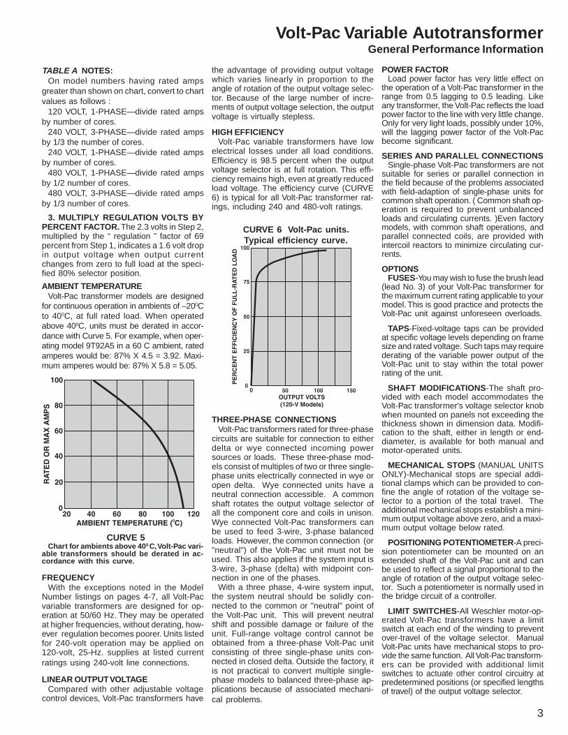
MOTOR OPERATING TIMEMotor operating time refers to the number of
seconds for the motor to traverse its full rangein one direction. In the motor-operated listing,most Volt-Pac model numbers are standard26-second motor operating time.
If you require motor operating times other thanthe 26 seconds, you drop the -G51 or -G54suffix in the Volt-Pac model listing and replace itwith a suffix from the table on page 9.
1. When over voltage connection is used, rated current should not be exceeded.2. When using extended tap connections, operation is for 60-hertz only.3. Output at overvoltage connection is 0-110% of input voltage.4. When operated with this input voltage, rated current must be reduced in accordance with Curve 1, page 2, when output voltage exceeds 140% of input voltage.5. 60 hertz only.
6. For line-voltage connection only, no overvoltage connection provided.7. Shipped connected for 0-100% of input voltage.8. Shipped connected for 0-117% of input voltage.9. Component listed by UL, uncased units only. Add suffix AIM to model No.10. Order 1 terminal enclosure kit per core to convert this model to
enclosed terminals.
Volt-Pac Variable Autotransformer
Weschler Instruments 440-238-2550 . Fax 440-238-0660 . E-mail: [email protected] . www.weschler.com

8
TERMINAL ARRANGEMENTSWeschler Instruments Volt-Pac trans-
former terminal boards are constructedand imprinted to facilitate connection toline and load. Most terminal boards aredesigned for ring or spade terminals and1/4" female quick-connect terminals. Thetable at right illustrates typical terminalconnections for many common ratings.Specific terminal details are shown withthe outline diagrams on pages 13-17.
CONNECTIONS FOR COMMONLY USED RATINGS
TERMINAL ARRANGEMENTS, CONNECTIONS AND WIRING
OPTIONS AND FEATURES MAY VARY BE-TWEEN MODELS, CONTACT FACTORY FORSPECIFICS. IN A CONSTANT EFFORT TO IM-PROVE OUR PRODUCTS, SPECIFICATIONSMAY CHANGE FROM THOSE PUBLISHED.
NOTES FOR CONNECTIONSNOTE 1.Connection diagrams for single-phase rat-ings using more than two cores, and for three-phase (wye) ratings using more than threecores, may be obtained by contacting yourWeschler Instrument sales representative.
NOTE 2.Ratings which have no tap connection uti-lize a three-terminal arrangement NOTshown in the adjacent connection diagrams.
NOTE 3.Three-phase unit is shipped with knob onthe end of unit opposite the base and withjumpers connecting terminals 1-1-1, (clock-wise rotation will raise voltage). If knob ismoved to the other end, remove jumpersfrom 1-1-1, and connect terminals 4-4-4 (thiswill maintain clockwise rotation to raise volt-age).
WIRING DIAGRAMSBelow are wiring diagrams for twobasic types of Volt-Pac variable
transformer connections.
Volt-Pac Variable Autotransformer
smargaiDlanimreT noitcennoC
desUslanimreT
gnitnuoMecafruSesiwkcolC(
nobonK)noitatoRetisoppOdnE
esaB
lenap-fo-kcaBgnitnuoMesiwkcolC(
nobonK)noitatoRdnEesaB
EMARF03,TUPTUOTLOV-231/021-0,TUPNITLOV-021,EROC-ELGNIS,ESAHP-ELGNIS
tupnItuptuO
V021V021-0
2-13-1
tupnItuptuO
V021V231-0
4-13-1
)EMARF03TPECXE(,TUPTUOTLOV-041/021-0,TUPNITLOV-021,EROC-ELGNIS,ESAHP-ELGNIS
tupnItuptuO
V021V021-0
4-13-1
1-43-4
tupnItuptuO
V021V041-0
2-13-1
5-43-4
,TUPNITLOV-042ROTLOV-021,EROC-ELGNIS,ESAHP-ELGNIS TUPTUOTLOV-082/042-0
tupnItuptuO
V021V082-0
6-13-1
7-43-4
tupnItuptuO
V042V042-0
4-13-1
1-43-4
tupnItuptuO
V042V082-0
2-13-1
5-43-4
TUPTUOTLOV-065/084-0,TUPNITLOV-084RO-042,EROC-OWT,ESAHP-ELGNIS
tupnItuptuOrepmuJ
V042V065-0
6-63-31-1
7-73-34-4
tupnItuptuOrepmuJ
V084V084-0
4-43-31-1
1-13-34-4
tupnItuptuOrepmuJ
V084V065-0
2-23-31-1
5-53-34-4
TUPTUOTLOV-082/042-0,TUPNITLOV-042,EROC-EERHT,)EYW(ESAHP-EEHRT
tupnItuptuOrepmuJ
V042V042-0
4-4-43-3-31-1-1
1-1-13-3-34-4-4
tupnItuptuOrepmuJ
V042V082-0
2-2-23-3-31-1-1
5-5-53-3-34-4-4
TUPTUOTLOV-065/084-0,TUPNITLOV-084RO-042,EROC-EERHT,)EYW(ESAHP-EERHT
tupnItuptuOrepmuJ
V042V065-0
6-6-63-3-31-1-1
7-7-73-3-34-4-4
tupnItuptuOrepmuJ
V084V084-0
4-4-43-3-31-1-1
1-1-13-3-34-4-4
tupnItuptuOrepmuJ
V084V065-0
2-2-23-3-31-1-1
5-5-53-3-34-4-4
TUPTUOTLOV-041/021-0,TUPNITLOV-042RO-021,EROC-OWT,)ATLEDNEPO(ESAHP-EERHTTUPTUOTLOV082./042-0,TUPNITLOV-042DNA
tupnItuptuOrepmuJ
V021V021-0
4-1-43-1-3
1-1
1-4-13-4-3
4-4
tupnItuptuOrepmuJ
V021V041-0
2-1-23-1-3
1-1
5-4-53-4-3
4-4
tupnItuptuOrepmuJ
V042V042-0
4-1-43-1-3
1-1
1-4-13-4-3
4-4
tupnItuptuOrepmuJ
V042V082-0
2-1-23-1-3
1-1
5-4-53-4-3
4-4

9
Motor operating time refers to the number of seconds for the motor to traverse its full range in one direction. In the motoroperated listing, most Volt-Pac model numbers are for standard 26.2 second motor operating time. If you require motor operat-ing time other than the 26.2, you must drop the G51 or G54 suffix in the Volt-Pac model listing and replace it with a suffix fromthe table below.
).ceS(noitarepOfoemiT .oNxiffuSddA ).ceS(noitarepOfoemiT .oNxiffuSddA
ztreh06 ztreh05 desacnU desaC ztreh06 ztreh05 desacnU desaC
*seziSemarF57dna06,05,04,03llAroF seziSemarF59dna58llAroF
4.4 3.5 12G 42G 7.3 4.4 12G 42G
1.31 7.51 14G 44G 7.8 4.01 13G 43G
2.62 4.13 15G 45G 2.81 8.12 14G 44G
6.45 6.56 16G 46G 2.62 4.13 15G 45G
6.45 5.56 16G 46G
SUFFIX TABLE
MOTOR OPERATING TIME
TERMINAL ENCLOSURE KITSWhen Volt-Pac models with enclosed ter-
minals are required, modification kits canbe purchased economically to convert ex-posed-terminal models to enclosed ones.A different terminal kit is available foreach Volt-Pac frame size. The frame sizeand number of cores for each Volt-Pacunit is listed in the third column of the
roFemarF
eziSrebmuNledoMredrO
03
05
06
57
58
elbaliavastikon
309Y81T9
2G309Y81T9
3G309Y81T9
4G309Y81T9
---------------
ylnotiK
ylnotiK
ylnotiK
ylnotiK
TERMINAL ENCLOSURE KIT
tables on pages 4-7. Always order a quan-tity of kits corresponding to the numberof cores. For example, when an enclosedversion of Volt-Pac Model 9T92A41G2 isdesired, order one (1) Volt-Pac Model No.9T92A41G2 and two (2) kits, Model No.9T18Y903G4. See dimensions below.
Note: Refer to pages 13-15 for detailed dimensions of cased models with exposed terminals. When proper Fig. No. from pages13-15 has been located, the diagrams and table below will provide overall dimensions for cased units with enclosed terminals.
.oN.giF.sgPmorF
51-31
emarF&eziSfo.oNseroC
sehcnInisnoisnemiD
A A1
3456
1-051-061-571-58
----------------------------------------
8/568/56
821
8012131
2-583-586-582-06
8/3214/1218/711
4/17
----------------------------------------
3141417171
3-062-573-572-053-05
4/178/588/584/174/17
--------------------------------------------------
DIMENSIONS - CASED MODELS with TERMINAL ENCLOSURE KIT
CONTROLKNOB
TERNINALENCLOSURE KIT
TOP VIEW
Volt-Pac Variable Autotransformer
Weschler Instruments 440-238-2550 . Fax 440-238-0660 . E-mail: [email protected] . www.weschler.com
10
Volt-Pac Automatic Voltage Regulator
SNOITACILPPA
:tsacdaorB eliboMdna,soidutS,srevieceR,srettimsnarTstinunoitcudorp
lairtsudnI : ,gnitaeHecnatsiseR,smetsySgnitalP,rotoMegraL,sehctulCdnasdioneloScitengaM,looTenihcaMtnempiuqEtseT,tnempiuqEnoitubirtsiD,sredleW
seilppuSrewoP
eniraM : rewoPerohSdnadraobpihSlaicremmoCdnaetavirPgninoitidnoC
laicremmoC : ecnasiuNSPU,srellihC,slortnoCrotavelE,gnithgiLsgnidliuBesiRhgiH,noitneverPpirT
lacideM : tnempiuqEnacSTAC,IRM,yaR-X
cinortcelE : snoitacinummoceleT,sretupmoC,radaR
SERUTAEF
%1±ycaruccAegatloVtuptuOtnellecxE ngiseDecnadepmIwoL
lacipyTycneiciffE%99 yticapaCdaolrevOhgiH
scinomraHronoitrotsiDmrofevaWoN ecnanetniaMwoL
rotcaFrewoPdaoLoTevitisneStoN 02- 0 04+ot 0 egnaRerutarepmeTgnitarepOtneibmAC
noitcerroCegatloVtsaF daoLotrewoPtpurretnItoNlliWnoitalugeRfossoL
egatloVtuptuOelbatsujdA segnahCycneuqerFotevitisnesnI
hctiwSrewoL-esiaRlaunaM )egnaRgnitarepOZH36-74(
tupnIworraNdnaediW elbatceleSegnaRegatloV
detnuoMkcaRrotenibaC sledoMesahP-eerhTdnaelgniS
erusolcnEfoorP-pirDdetalitneVroodnI elbaliavAsledoMdetaRAVK005ot5.1
dedulcnIretemtloVtuptuO tiucriClortnoCdesuF
ytnarraWraeY-enO
SNOITPO
lortnoClatigiD sretemmA
segnaRtupnIdetfihS stcatnoCmralAegnaRegatloVtupnI
reteMycneuqerF
rebmuNgolataC)sehcnI(snoisnemiD
A B C
011,901,401,301,201,1010C29T9 4/302 61/1191 8/59
111,5010D29T9 8/702 22 8/131
211,6010D29T9 2/122 22 2/132
3OG511,30G4110C29T9 61/142 8/771 4/351
121,511,4110C29T9 4/352 61/591 8/561
6110D29T9 4/312 4/181 02
861,551,031,521,7110D29T9 52 2/102 03
821,721,321,2210C29T9 4/151 8/361 72
071,921,421D29T9 02 91 03
671,451D29T9 2/113 2/122 2/156
761D29T9 2/133 2/102 2/127
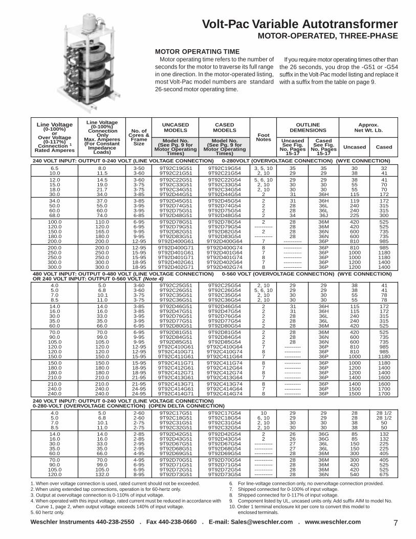
Almost every aspectof our lives is affectedwhen electric powerbecomes unstable.Dependence on qualitypower increases whilepower problemsbecome morepredominate.Generation capacityand the distributionsystem have not keptpace with increaseddemand for electricity.Competition forcesequipmentmanufacturers to pushcomponent limits,making them moresensitive to voltagefluctuations. Manyelectrical loads nowcreate voltageimbalances due to nonsinusoidal currentdraw. Power companycorrections for lowvoltage in one arearesult in high voltagein another. Poor powerquality is a silent killercausing unexplainedequipment glitches andpremature failures,increasing downtimeand cost. Surveysshow voltage sagsrepresent 87% of shortterm powerdisturbances. VoltPacVoltage Regulatorssolve voltageregulation problems byproviding ±1% orbetter output voltageregulation over theirbroad input range.Proven techniquescombined with highquality componentsprovide highly reliable,99% efficient units withgenerous ratings andhigh momentaryoverload capacity.

11
Volt-Pac Automatic Voltage Regulator
Weschler Instruments 440-238-2550 . Fax 440-238-0660 . E-mail: [email protected] . www.weschler.com

12
DIMENSIONS
VoltPac Full Range Regulator / Controller
Applications Features
Electric Motor testing Quality control labs Microprocessor controller Regulation to +/- .5 voltsPlating rectifier systems Voltage regulators High visibility LED display Up to 3 control channelsCompressor testing Lamp & ballast testing Non volatile memory Std RS-232 com. PortIndustrial processes Power Supplies True RMS sensing Adjustable deadbandAppliance testing Telecom equipment testing Autoranging to 600 volts Automatic regulation
Specifications Options
Input signal 0 – 600 ACV Auto ranging RS – 422 CommunicationsController Power 120 VAC 50 or 60 HZ @ 5 watts max RS – 485 CommunicationsControl outputs Solid state relay 3 A 120 voltAccuracy +/- 0.4 VACResponse time less than 0.1 secCommunications 9600 Baud,8 bits, No parity, 1 stop bitMotor speed High or LowControl modes single line, independent phase or bypassDeadband 0 – 99.9 voltsPulse adjust 0 – 99 volts
The VoltPac 9T92PVC2 Full Range Regulator Controller is an intelligent microprocessorbased unit. It regulates the output / load voltage of a motor operated variable voltagetransformer to a user programmed value. These flexible units allow for operator definitionof set point, dead-band, operating mode, frequency, and motor speed. Parameters areinput through the keypad or serial 232, 422 or 485 ASCII communications port. The 5 digit7 segment LED display provides local indication of output voltage and programmed set-tings. All parameters are also available through the serial port allowing for remote moni-toring and control of the unit. Keypad lockout, and auto / manual control capability allowapplication flexibility. The unit may be configured for one, two or three control channels foruse on single and polyphase systems with single line or independent phase control. Themotor pulsing feature allows for fine adjustment of the output without overshoot.
For Use With Any Synchronous MotorDriven Variable Autotransformer
Mounting Schematic
Volt-Pac Variable Autotransformer
noitarugifnoCrebmuNledoM
ledoM noitarugifnoC
-2CVP29T9
slennahC snoitacinummoC
1 232SRA
2 224SRB
3 584SRC
2CVP29T9 -

Fig. 1 Frame 30 - 1 core
Fig. 6 Frame 85 - 1 core
Fig. 3 Frame 50 - 1 core
Fig. 2 Frame 40 - 1 core
Fig. 4 Frame 60 - 1 core
Fig. 5 Frame 75 - 1 core
Fig. 7 Frame 95 - 1 core
Fig. 8 Frame 85 - 2 core
DIMENSIONS for Manual, Single and Three-Phase
13
DIMENSIONSVolt-Pac Variable Autotransformer
Weschler Instruments 440-238-2550 . Fax 440-238-0660 . E-mail: [email protected] . www.weschler.com

14
Fig. 9 Frame 95 - 2 core
Fig. 14 Frame 75 - 2, 3 cores
Fig. 11 Frame 95 - 3, 4, 5, 6 cores
Fig. 10 Frame 85 - 3 core
Fig. 12 Frame 85 - 6 core
Fig. 13 Frame 60 - 2, 3 cores
Fig. 15 Frame 30 - 2, 3 cores
Fig. 16 Frame 40 - 2, 3 cores
DIMENSIONS for Manual, Single and Three-Phase (Continued)
Volt-Pac Variable Autotransformer

15
Fig. 18 Terminal DetailsFig. 17 Frame 50 - 2, 3 cores
DIMENSIONS for Manual, Single and Three-Phase (Continued)
Fig. 19 Frame 30 - 1 core Fig. 21 Frame 50 - 1 core
Fig. 20 Frame 40 - 1 core Fig. 22 Frame 60 - 1 core
DIMENSIONS for Motor operated, single and three phase
DIMENSIONSVolt-Pac Variable Autotransformer
Weschler Instruments 440-238-2550 . Fax 440-238-0660 . E-mail: [email protected] . www.weschler.com
Terminal Detail A is applicable only to 75-frame Volt-Pac transformers,
Detail B applies only to Frame-85 and 95.

16
DIMENSIONS
Fig. 23 Frame 75 - 1 core
Fig. 28 Frame 95 - 3, 4, 5, 6, 8, 9 core
Fig. 25 Frame 95 - 1 core
Fig. 24 Frame 85 - 1 core
Fig. 26 Frame 85 - 2 core
Fig. 27 Frame 95 - 2 core
Fig. 29 Frame 60 - 2, 3 cores
Fig. 30 Frame 75 - 2, 3 cores
MOTOR OPERATED, SINGLE AND THREE-PHASE (CONTINUED)
Volt-Pac Variable Autotransformer

noisnemiDecnerefeR
sehcninisnoisnemiD
htdiW htpeD thgieHA63B63C63D63
00.6100.1200.1200.12
00.7105.7105.7105.71
05.852.7100.3200.23
E63F63G63H63
00.1200.6100.6100.61
05.7105.7105.7105.71
00.4400.3205.0305.53
J63K63L63M63N63P63
00.6100.5100.1200.1200.1200.25
05.7100.7105.7105.7105.7100.02
05.8400.3200.4300.2500.0700.25
Fig. 31 Frame 85 - 3 cores
Fig. 35 Frame 50 - 2, 3 cores
Fig. 33 Frame 40 - 2, 3, cores
Fig. 32 Frame 30 - 2, 3 cores
Fig. 34 Frame 85 - 6 cores
Fig. 36 Cased unit dimensions
MOTOR OPERATED, SINGLE AND THREE-PHASE (CONTINUED)
DIMENSIONS
17
Volt-Pac Variable Autotransformer
Weschler Instruments 440-238-2550 . Fax 440-238-0660 . E-mail: [email protected] . www.weschler.com