voltec battery design and manufacturing · 2015-02-16 · voltec battery design and manufacturing...
TRANSCRIPT
EVS28KINTEX, Korea, May 3-6, 2015
Voltec Battery Design and
Manufacturing
Milind GandhiGeneral Motors Korea
Introduction
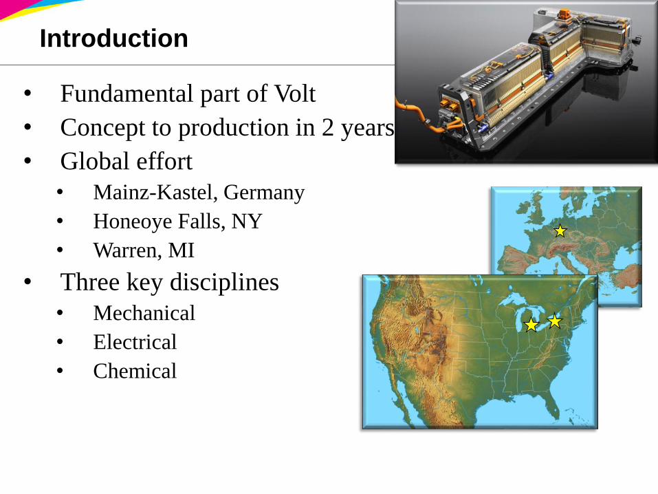
• Fundamental part of Volt
• Concept to production in 2 years
• Global effort
• Mainz-Kastel, Germany
• Honeoye Falls, NY
• Warren, MI
• Three key disciplines
• Mechanical
• Electrical
• Chemical
Organization
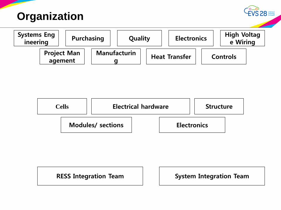
Systems Engineering
Project Management
Purchasing
Manufacturing
Quality
Heat Transfer
Electronics
Controls
High Voltage Wiring
Cells
Modules/ sections
Electrical hardware
Electronics
Structure
RESS Integration Team System Integration Team
Organization
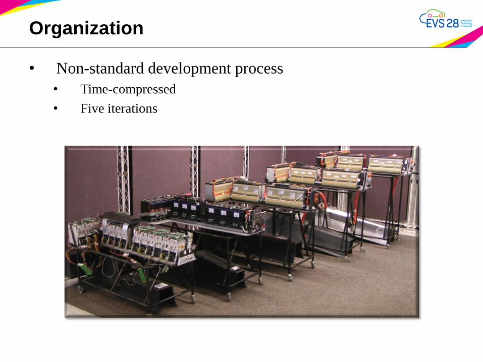
• Non-standard development process
• Time-compressed
• Five iterations
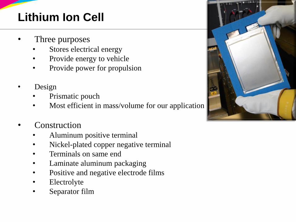
Lithium Ion Cell
• Three purposes• Stores electrical energy
• Provide energy to vehicle
• Provide power for propulsion
• Design
• Prismatic pouch
• Most efficient in mass/volume for our application
• Construction• Aluminum positive terminal
• Nickel-plated copper negative terminal
• Terminals on same end
• Laminate aluminum packaging
• Positive and negative electrode films
• Electrolyte
• Separator film
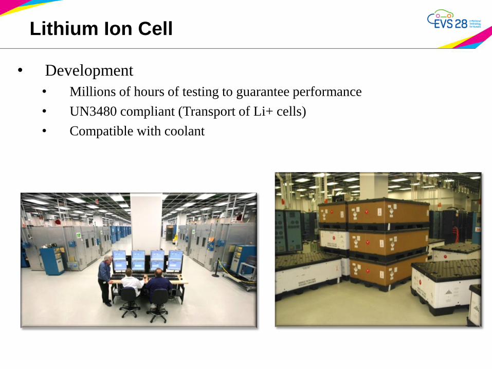
Lithium Ion Cell
• Development
• Millions of hours of testing to guarantee performance
• UN3480 compliant (Transport of Li+ cells)
• Compatible with coolant
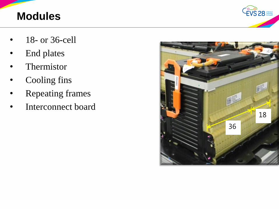
Modules
• 18- or 36-cell
• End plates
• Thermistor
• Cooling fins
• Repeating frames
• Interconnect board
36
18
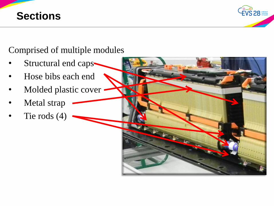
Sections
Comprised of multiple modules
• Structural end caps
• Hose bibs each end
• Molded plastic cover
• Metal strap
• Tie rods (4)
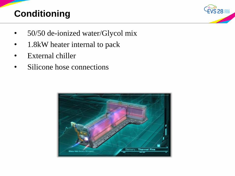
Conditioning
• 50/50 de-ionized water/Glycol mix
• 1.8kW heater internal to pack
• External chiller
• Silicone hose connections
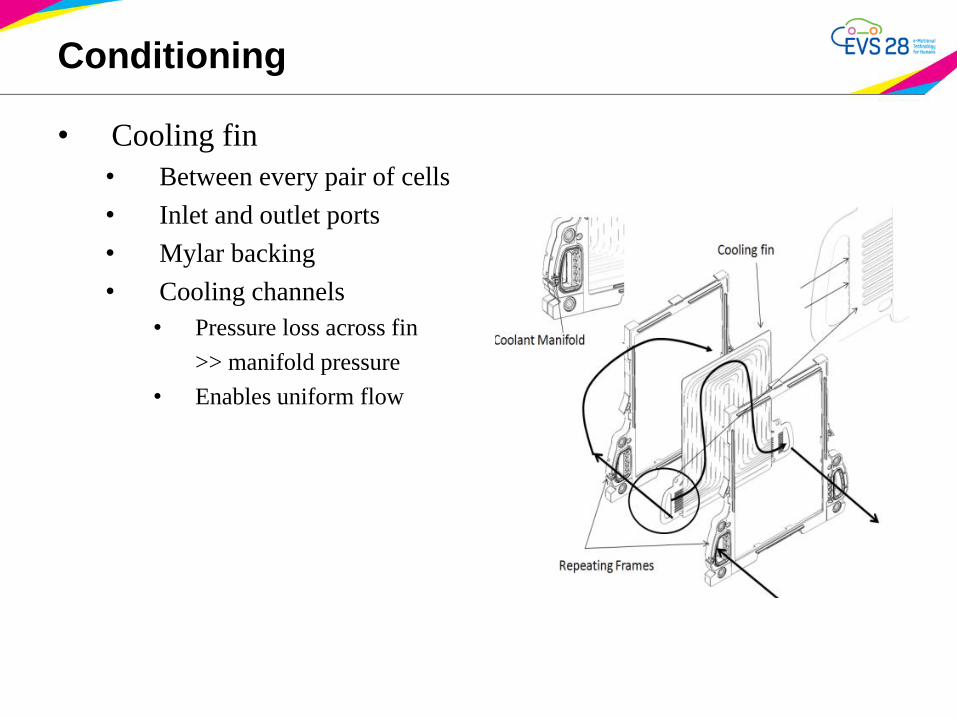
Conditioning
• Cooling fin
• Between every pair of cells
• Inlet and outlet ports
• Mylar backing
• Cooling channels
• Pressure loss across fin
>> manifold pressure
• Enables uniform flow
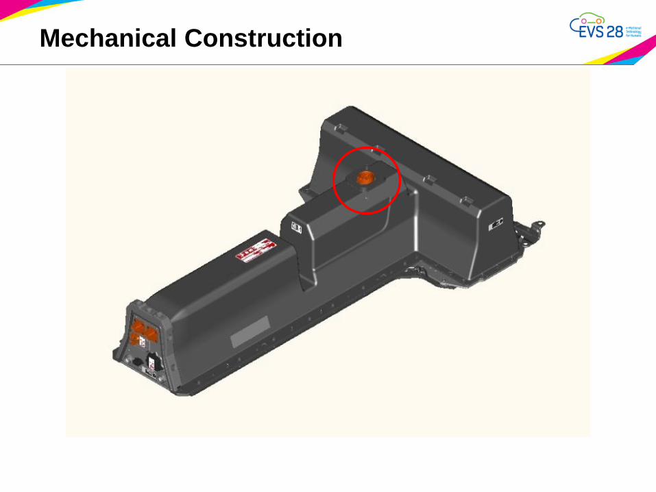
Mechanical Construction
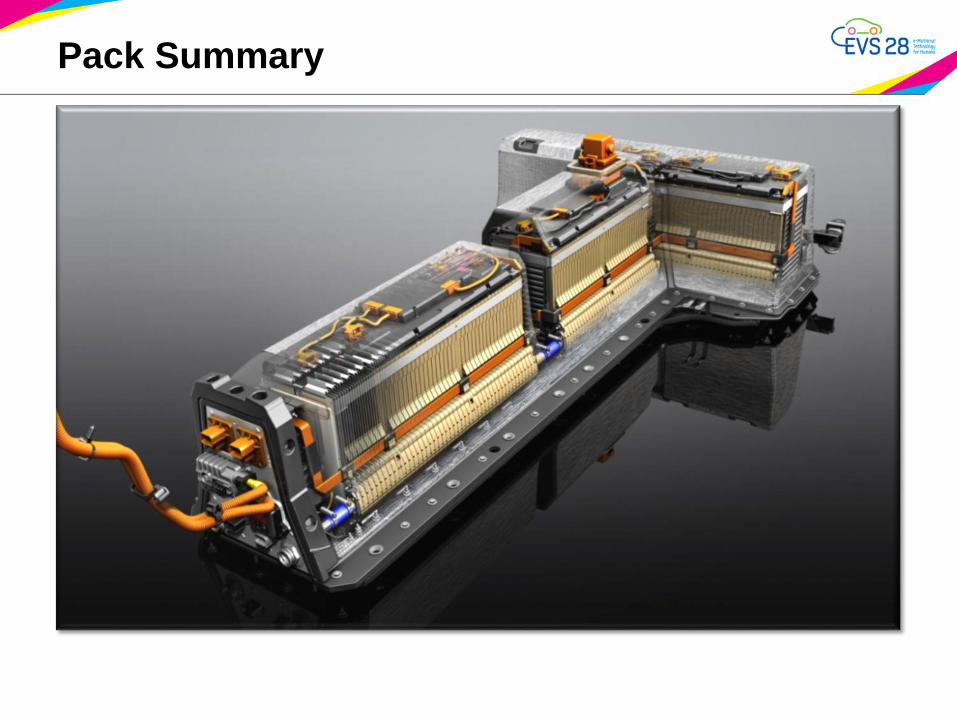
Pack Summary
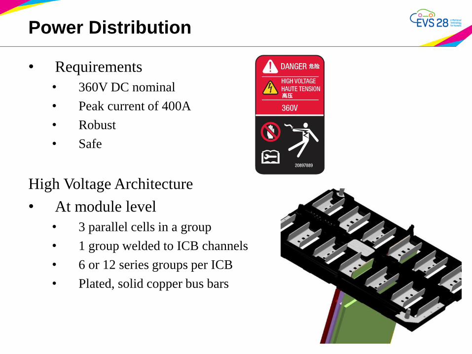
Power Distribution
• Requirements
• 360V DC nominal
• Peak current of 400A
• Robust
• Safe
High Voltage Architecture
• At module level
• 3 parallel cells in a group
• 1 group welded to ICB channels
• 6 or 12 series groups per ICB
• Plated, solid copper bus bars
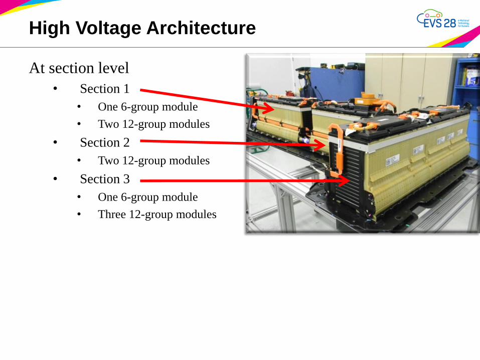
High Voltage Architecture
At section level
• Section 1
• One 6-group module
• Two 12-group modules
• Section 2
• Two 12-group modules
• Section 3
• One 6-group module
• Three 12-group modules
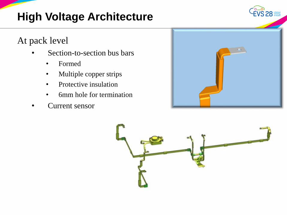
High Voltage Architecture
At pack level
• Section-to-section bus bars
• Formed
• Multiple copper strips
• Protective insulation
• 6mm hole for termination
• Current sensor
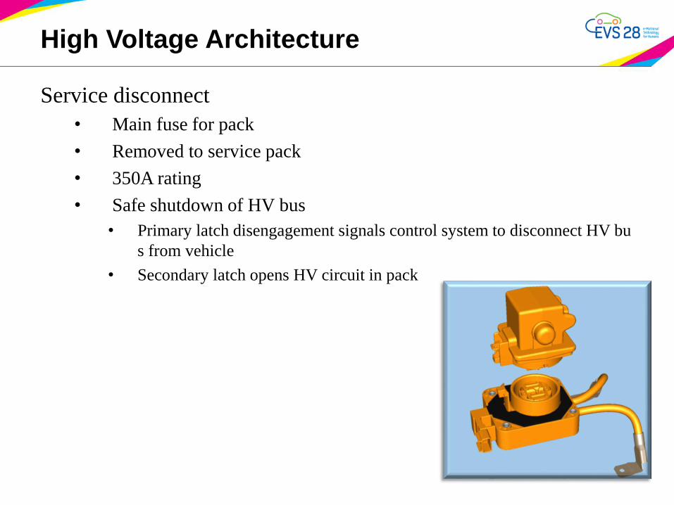
Service disconnect
• Main fuse for pack
• Removed to service pack
• 350A rating
• Safe shutdown of HV bus
• Primary latch disengagement signals control system to disconnect HV bu
s from vehicle
• Secondary latch opens HV circuit in pack
High Voltage Architecture
High Voltage Architecture
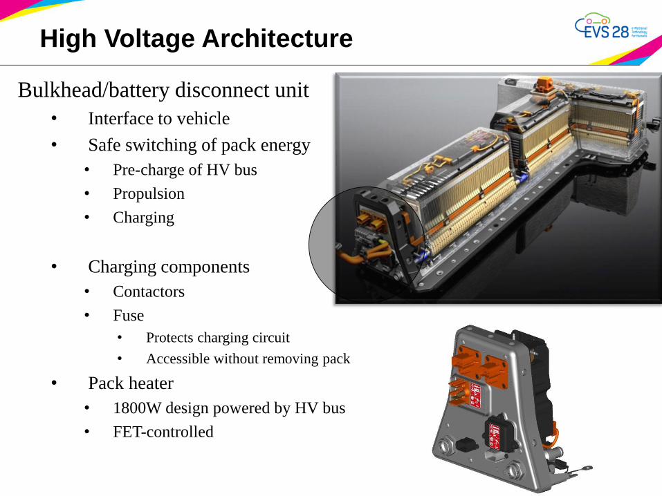
Bulkhead/battery disconnect unit
• Interface to vehicle
• Safe switching of pack energy
• Pre-charge of HV bus
• Propulsion
• Charging
• Charging components
• Contactors
• Fuse
• Protects charging circuit
• Accessible without removing pack
• Pack heater
• 1800W design powered by HV bus
• FET-controlled
Low Voltage Architecture
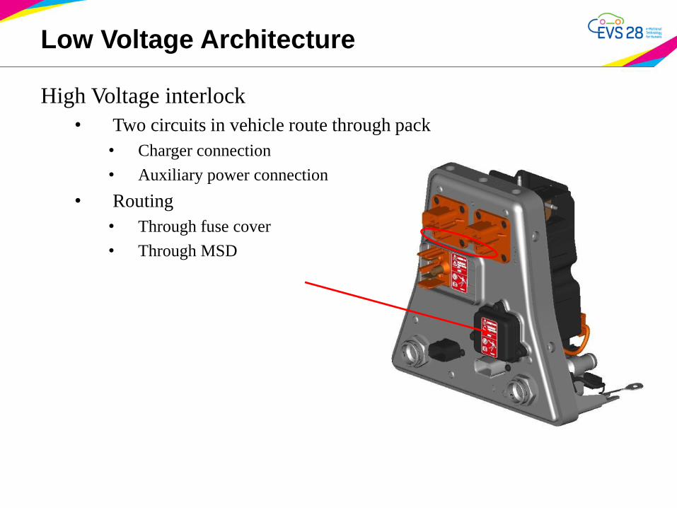
High Voltage interlock
• Two circuits in vehicle route through pack
• Charger connection
• Auxiliary power connection
• Routing
• Through fuse cover
• Through MSD
Low Voltage Architecture
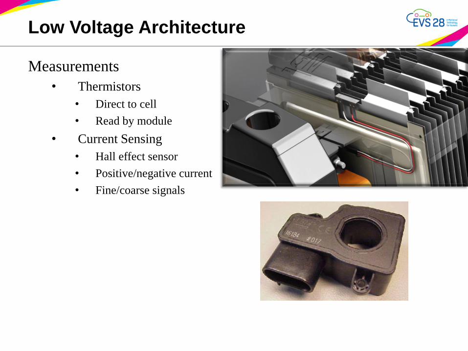
Measurements
• Thermistors
• Direct to cell
• Read by module
• Current Sensing
• Hall effect sensor
• Positive/negative current
• Fine/coarse signals
Electronics
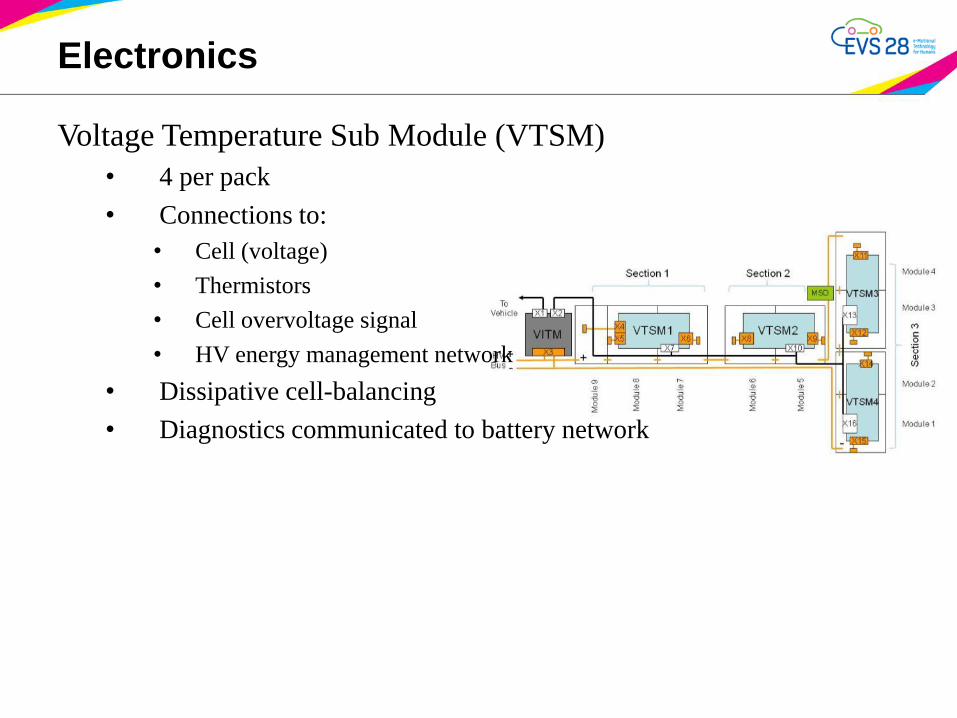
Voltage Temperature Sub Module (VTSM)
• 4 per pack
• Connections to:
• Cell (voltage)
• Thermistors
• Cell overvoltage signal
• HV energy management network
• Dissipative cell-balancing
• Diagnostics communicated to battery network
Electronics
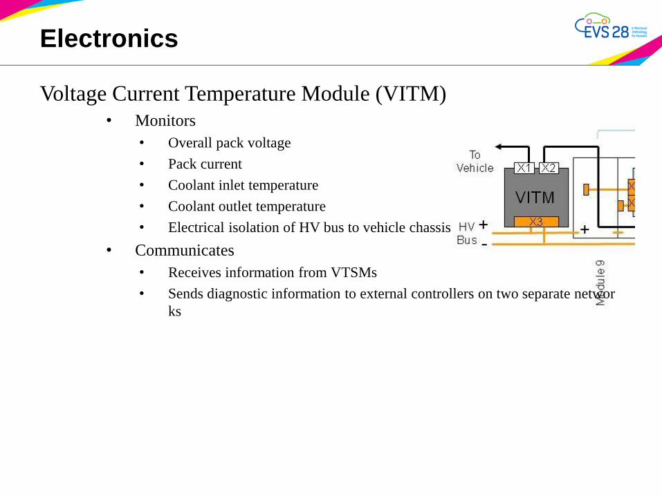
Voltage Current Temperature Module (VITM)
• Monitors
• Overall pack voltage
• Pack current
• Coolant inlet temperature
• Coolant outlet temperature
• Electrical isolation of HV bus to vehicle chassis
• Communicates
• Receives information from VTSMs
• Sends diagnostic information to external controllers on two separate networ
ks
Manufacturing Systems
Requires balance of speed and precision
• Upstream processes require high speeds
• Relatively low volume of packs
Manufacturing Systems
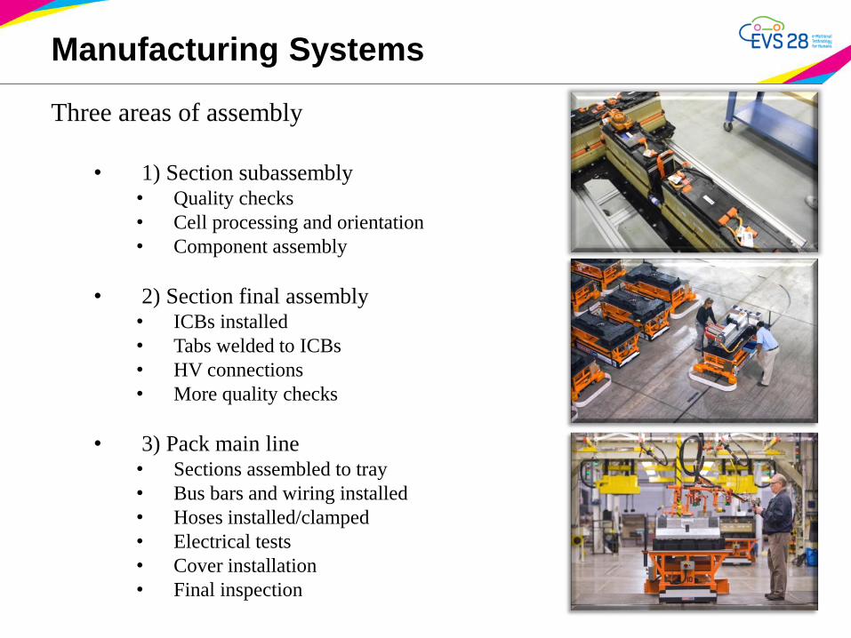
Three areas of assembly
• 1) Section subassembly• Quality checks
• Cell processing and orientation
• Component assembly
• 2) Section final assembly• ICBs installed
• Tabs welded to ICBs
• HV connections
• More quality checks
• 3) Pack main line• Sections assembled to tray
• Bus bars and wiring installed
• Hoses installed/clamped
• Electrical tests
• Cover installation
• Final inspection
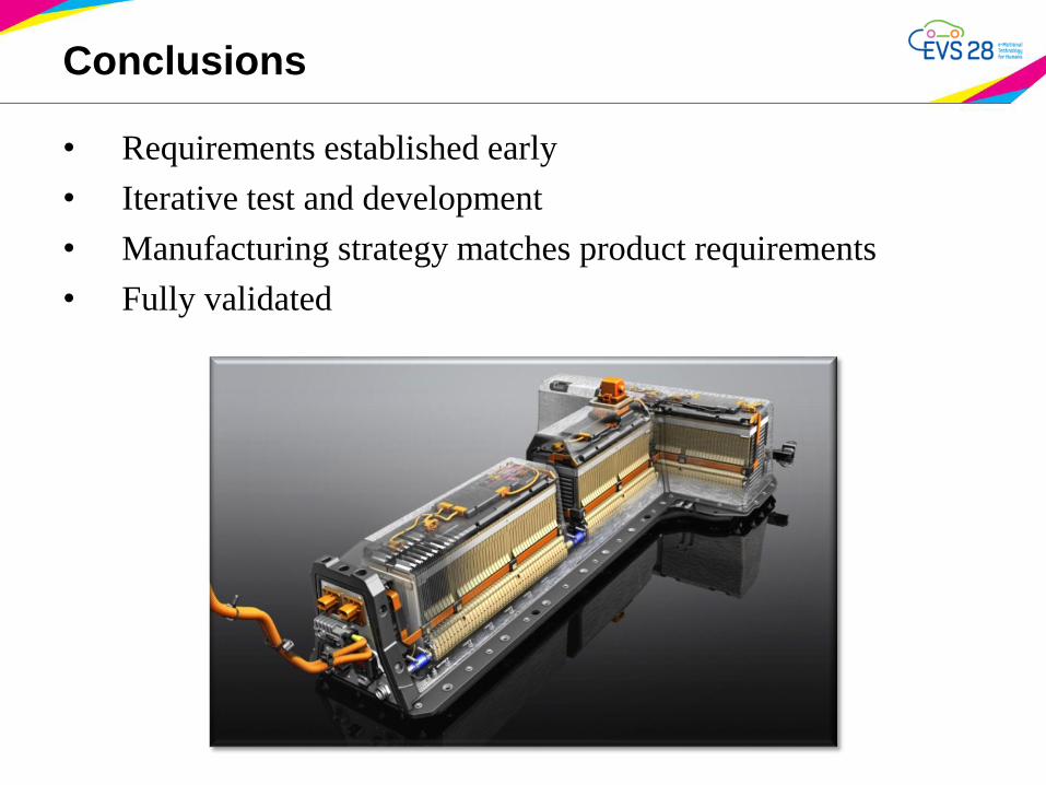
Conclusions
• Requirements established early
• Iterative test and development
• Manufacturing strategy matches product requirements
• Fully validated