volume 11 tab 2 - farnell · volume 11—vehicle and commercial controls ca08100013e—december...
TRANSCRIPT

Volume 11—Vehicle and Commercial Controls CA08100013E—December 2015 www.eaton.com V11-T2-1
2
2
2
2
2
2
2
2
2
2
2
2
2
2
2
2
2
2
2
2
2
2
2
2
2
2
2
2
2
2
Rockers
NGR
SVR
Rockette
EURO SR
ESPORT
2.1 Introduction
Product Selection Guide . . . . . . . . . . . . . . . . . . . . . . . . . . . . . . . . . . . . V11-T2-3
2.2 NGR
Product Description . . . . . . . . . . . . . . . . . . . . . . . . . . . . . . . . . . . . . . . V11-T2-8
Catalog Number Selection . . . . . . . . . . . . . . . . . . . . . . . . . . . . . . . . . . V11-T2-10
2.3 SVR
Product Description . . . . . . . . . . . . . . . . . . . . . . . . . . . . . . . . . . . . . . . V11-T2-32
Catalog Number Selection . . . . . . . . . . . . . . . . . . . . . . . . . . . . . . . . . . V11-T2-34
2.4 Dual Motion Safety Switch
Product Description . . . . . . . . . . . . . . . . . . . . . . . . . . . . . . . . . . . . . . . V11-T2-43
Catalog Number Selection . . . . . . . . . . . . . . . . . . . . . . . . . . . . . . . . . . V11-T2-44
2.5 1500/2500
Product Description . . . . . . . . . . . . . . . . . . . . . . . . . . . . . . . . . . . . . . . V11-T2-45
Catalog Number Selection . . . . . . . . . . . . . . . . . . . . . . . . . . . . . . . . . . V11-T2-46
2.6 1600/2600
Product Description . . . . . . . . . . . . . . . . . . . . . . . . . . . . . . . . . . . . . . . V11-T2-49
Catalog Number Selection . . . . . . . . . . . . . . . . . . . . . . . . . . . . . . . . . . V11-T2-50
2.7 Rockette
Product Description . . . . . . . . . . . . . . . . . . . . . . . . . . . . . . . . . . . . . . . V11-T2-56
Catalog Number Selection . . . . . . . . . . . . . . . . . . . . . . . . . . . . . . . . . . V11-T2-57
2.8 8006/8007—EURO SR
Product Description . . . . . . . . . . . . . . . . . . . . . . . . . . . . . . . . . . . . . . . V11-T2-64
Catalog Number Selection . . . . . . . . . . . . . . . . . . . . . . . . . . . . . . . . . . V11-T2-65
2.9 8004/8005—Euro Full Size
Product Description . . . . . . . . . . . . . . . . . . . . . . . . . . . . . . . . . . . . . . . V11-T2-67
Catalog Number Selection . . . . . . . . . . . . . . . . . . . . . . . . . . . . . . . . . . V11-T2-68
2.10 X Series
Product Description . . . . . . . . . . . . . . . . . . . . . . . . . . . . . . . . . . . . . . . V11-T2-70
Catalog Number Selection . . . . . . . . . . . . . . . . . . . . . . . . . . . . . . . . . . V11-T2-71
X Series Symbols Library . . . . . . . . . . . . . . . . . . . . . . . . . . . . . . . . . . . V11-T2-72
2.11 8064/8065 ESPORT
Product Description . . . . . . . . . . . . . . . . . . . . . . . . . . . . . . . . . . . . . . . V11-T2-74
Catalog Number Selection . . . . . . . . . . . . . . . . . . . . . . . . . . . . . . . . . . V11-T2-75
Icon/Legend Selection . . . . . . . . . . . . . . . . . . . . . . . . . . . . . . . . . . . . . V11-T2-76
2.12 Accessories
Dimensions . . . . . . . . . . . . . . . . . . . . . . . . . . . . . . . . . . . . . . . . . . . . . V11-T2-78
2.13 Technical Data
Rocker, Toggle and Pushbuttons . . . . . . . . . . . . . . . . . . . . . . . . . . . . . V11-T2-80
Rocker Switch Circuit Diagrams . . . . . . . . . . . . . . . . . . . . . . . . . . . . . . V11-T2-81
2.14 Symbol Library
NGR, SVR, E31, E32 and E33 eSM Symbols . . . . . . . . . . . . . . . . . . . . V11-T2-82
NGR Only Symbols . . . . . . . . . . . . . . . . . . . . . . . . . . . . . . . . . . . . . . . V11-T2-87
SVR, E31, E32 and E33 eSM Symbols . . . . . . . . . . . . . . . . . . . . . . . . V11-T2-97

V11-T2-2 Volume 11—Vehicle and Commercial Controls CA08100013E—December 2015 www.eaton.com
2
2
2
2
2
2
2
2
2
2
2
2
2
2
2
2
2
2
2
2
2
2
2
2
2
2
2
2
2
2
2.1 Rockers
Introduction
Rocker Switch Products ContentsDescription
Rocker Selection Guide . . . . . . . . . . . . . . . . . . . . . V11-T2-3
NGR Rocker Switches . . . . . . . . . . . . . . . . . . . . . . V11-T2-8
SVR—Sealed Vehicle Rockers . . . . . . . . . . . . . . . . V11-T2-32
Dual Motion Safety Switches. . . . . . . . . . . . . . . . . V11-T2-43
1500/2500—Midsize AC Rated . . . . . . . . . . . . . . . V11-T2-45
1600/2600—Midsize AC Only . . . . . . . . . . . . . . . . V11-T2-49
Rockette—General Purpose AC Rated . . . . . . . . . . V11-T2-56
8006/8007—EURO SR. . . . . . . . . . . . . . . . . . . . . . V11-T2-64
8004/8005—Euro Full Size . . . . . . . . . . . . . . . . . . . V11-T2-67
X Series Rockers . . . . . . . . . . . . . . . . . . . . . . . . . . V11-T2-70
8064/8065—ESPORT. . . . . . . . . . . . . . . . . . . . . . . V11-T2-74
Accessories . . . . . . . . . . . . . . . . . . . . . . . . . . . . . . V11-T2-78
Technical Data . . . . . . . . . . . . . . . . . . . . . . . . . . . . V11-T2-80
Symbols Library . . . . . . . . . . . . . . . . . . . . . . . . . . . V11-T2-82

Volume 11—Vehicle and Commercial Controls CA08100013E—December 2015 www.eaton.com V11-T2-3
2
2
2
2
2
2
2
2
2
2
2
2
2
2
2
2
2
2
2
2
2
2
2
2
2
2
2
2
2
2
2.1Rockers
Introduction
Rocker Selection GuideSee Technical Data and Dimensions for more details.
Rocker Switches—Illuminated and Non-Illuminated
NGR SVR
Features
Ratings 15A at 125 Vac, 10A at 250 Vac; 15A at 28 Vdc (14 Vdc rating)
12A at either 12 or 24 Vdc
Certifications RoHS, UL® Approvable RoHS, UL Approvable
Panel Opening Rectangular Octagonal
Single- and two-pole length Single-pole width Two-pole width
1.734 in (44.04 ± 0.13 mm)0.867 in (22.02 ± 0.13 mm)0.867 in (22.02 ± 0.13 mm)
0.830 in (21.10 mm); 0.680 in (17.30 mm)1.450 in (36.80 mm); 1.190 in (30.20 mm)1.450 in (36.80 mm); 1.190 in (30.20 mm)
Seal Top (internal) Bottom (internal) Panel
✔ —✔
✔ ✔ ✔
Actuator Rocker without bezel Rocker with bezel Paddle Snap-in lens Locking Label
—✔ ✔ ✔ ✔ ✔
✔ ✔ ✔ ✔ ——
Decorative Laser-etch Pad-print
✔ ✔
✔ ✔
Poles Single Double Four
✔ ✔ —
✔ ✔ —
Termination Spade Solder Screw Weld lugs
✔ ———
✔ ———
Illumination Incandescent 6 Vdc Incandescent 12 Vdc Incandescent 14 Vdc Incandescent 18 Vdc Incandescent 24 Vdc Incandescent 28 Vdc Neon 110V Neon 125V Neon 250V 14V LED 28V LED
——✔ ✔ —✔ ———✔ ✔
—————————✔ ✔
Catalog Number Selection Page V11-T2-10 Page V11-T2-34
Technical Data Page V11-T2-16 Page V11-T2-36
Circuit Diagrams Page V11-T2-17 Page V11-T2-37
Dimensions Page V11-T2-30 Page V11-T2-38
Icon/Legend Symbols Library Page V11-T2-82 Page V11-T2-82

V11-T2-4 Volume 11—Vehicle and Commercial Controls CA08100013E—December 2015 www.eaton.com
2
2
2
2
2
2
2
2
2
2
2
2
2
2
2
2
2
2
2
2
2
2
2
2
2
2
2
2
2
2
2.1 Rockers
Introduction
See Technical Data and Dimensions for more details.
Rocker Switches—Illuminated and Non-Illuminated, continued
Dual Motion Safety Switch 1500/2500
Features
Ratings 10A at 250 Vac, 15A at 125 Vac, 3/4 hp at 250 Vac
Up to 22A at 125 Vac, 16A at 250 Vac
Certifications UL, CSA®, RoHS UL, CSA, ENEC, RoHS
Panel Opening Octagonal Rectangular
Single- and two-pole length Single-pole width Two-pole width
1.450 in (36.80 mm); 1.190 in (30.20 mm)0.830 in (21.10 mm); 0.680 in (17.20 mm)N/A
1.075 in (27.30 ± 0.10 mm)0.483 in (12.27 ± 0.07 mm)0.876 in (22.25 ± 0.10 mm)
Seal Top (internal) Bottom (internal) Panel
———
———
Actuator Rocker without bezel Rocker with bezel Paddle Snap-in lens Locking Label
—✔ ✔ ———
—✔ ✔ ———
Decorative Laser-etch Pad-print
—✔
—✔
Poles Single Double Four
✔ ——
✔ ✔ —
Termination
Spade Solder Screw Weld lugs
✔ ✔ ✔ —
✔ ✔ ——
Illumination Incandescent 6 Vdc Incandescent 12 Vdc Incandescent 14 Vdc Incandescent 18 Vdc Incandescent 24 Vdc Incandescent 28 Vdc Neon 110V Neon 125V Neon 250V 14V LED 28V LED
———————————
✔ ✔ ——✔ ——✔ ✔ ——
Catalog Number Selection Page V11-T2-44 Page V11-T2-46
Technical Data — Page V11-T2-48
Circuit Diagrams — Page V11-T2-80
Dimensions Page V11-T2-44 Page V11-T2-48
Icon/Legend Symbols Library — Page V11-T2-55

Volume 11—Vehicle and Commercial Controls CA08100013E—December 2015 www.eaton.com V11-T2-5
2
2
2
2
2
2
2
2
2
2
2
2
2
2
2
2
2
2
2
2
2
2
2
2
2
2
2
2
2
2
2.1Rockers
Introduction
See Technical Data and Dimensions for more details.
Rocker Switches—Illuminated and Non-Illuminated, continued
1600/2600 Rockette
Features
Ratings Up to 22A at 125 Vac, 16A at 250 Vac Up to 15A at 125 Vac, 10A at 250 Vac, 3/4 hp at 250 Vac
Certifications UL, CSA, ENEC, RoHS UL, CSA, RoHS
Panel Opening Rectangular Octagonal
Single- and two-pole length Single-pole width Two-pole width
1.075 in (27.30 ± 0.10 mm)0.483 in (12.27 ± 0.07 mm)0.876 in (22.25 ± 0.10 mm)
1.450 in (36.83 mm); 1.190 in (30.23 mm)0.830 in (21.80 mm); 0.680 in (17.27 mm)0.830 in (21.80 mm); 0.680 in (17.27 mm)
Seal Top (internal) Bottom (internal) Panel
———
✔ ——
Actuator Rocker without bezel Rocker with bezel Paddle Snap-in lens Locking Label
—✔ ✔ ———
—✔ ————
Decorative Laser-etch Pad-print
—✔
—✔
Poles Single Double Four
✔ ✔ —
—✔ ✔
Termination
Spade Solder Screw Weld lugs
✔ ✔ ——
✔ ✔ ✔ —
Illumination Incandescent 6 Vdc Incandescent 12 Vdc Incandescent 14 Vdc Incandescent 18 Vdc Incandescent 24 Vdc Incandescent 28 Vdc Neon 110V Neon 125V Neon 250V 14V LED 28V LED
✔ ✔ ——✔ ——————
——✔ ——✔ ✔ ————
Catalog Number Selection Page V11-T2-50 Page V11-T2-57
Technical Data Page V11-T2-54 Page V11-T2-60
Circuit Diagrams Page V11-T2-80 Page V11-T2-80
Dimensions Page V11-T2-54 Page V11-T2-60
Icon/Legend Symbols Library Page V11-T2-55 —

V11-T2-6 Volume 11—Vehicle and Commercial Controls CA08100013E—December 2015 www.eaton.com
2
2
2
2
2
2
2
2
2
2
2
2
2
2
2
2
2
2
2
2
2
2
2
2
2
2
2
2
2
2
2.1 Rockers
Introduction
See Technical Data and Dimensions for more details.
Rocker Switches—Illuminated and Non-Illuminated, continued
8006/8007 8004/8005
Features
Ratings 10A at 250 Vac, 15A at 125 Vac, 3/4 hp at 250 Vac, recommended up to 15A at 28 Vdc
10A at 250 Vac, 15A at 125 Vac, 3/4 hp at 250 Vac, recommended up to 15A at 28 Vdc
Certifications UL(CUR), RoHS UL(CUR), RoHS
Panel Opening Octagonal Rectangular
Single- and two-pole length Single-pole width Two-pole width
1.450 in (36.85 mm); 1.190 in (30.23 mm)0.830 in (21.08 mm); 0.680 in (17.27 mm)0.830 in (21.08 mm); 0.680 in (17.27 mm)
1.734 in (44.04 ± 0.13 mm)0.867 in (22.02 ± 0.13 mm)0.867 in (22.02 ± 0.13 mm)
Seal Top (internal) Bottom (internal) Panel
✔ ——
✔ ——
Actuator Rocker without bezel Rocker with bezel Paddle Snap-in lens Locking Label
—✔ ✔ ✔ ——
—✔ —✔ —✔
Decorative Laser-etch Pad-print
—✔
—✔
Poles Single Double Four
✔ ✔ —
✔ ✔ —
Termination
Spade Solder Screw Weld lugs
✔ ✔ ✔ —
✔ ✔ ✔ —
Illumination Incandescent 6 Vdc Incandescent 12 Vdc Incandescent 14 Vdc Incandescent 18 Vdc Incandescent 24 Vdc Incandescent 28 Vdc Neon 110V Neon 125V Neon 250V 14V LED 28V LED
——✔ ✔ —✔ —✔ ✔ ——
——✔ ✔ —✔ —✔ ✔ ——
Catalog Number Selection Page V11-T2-65 Page V11-T2-68
Technical Data Page V11-T2-66 Page V11-T2-69
Circuit Diagrams Page V11-T2-80 Page V11-T2-80
Dimensions Page V11-T2-66 Page V11-T2-69
Icon/Legend Symbols Library — —

Volume 11—Vehicle and Commercial Controls CA08100013E—December 2015 www.eaton.com V11-T2-7
2
2
2
2
2
2
2
2
2
2
2
2
2
2
2
2
2
2
2
2
2
2
2
2
2
2
2
2
2
2
2.1Rockers
Introduction
See Technical Data and Dimensions for more details.
Rocker Switches—Illuminated and Non-Illuminated, continued
X Series 8064/8065
Features
Ratings 16A 125V, 10A 277V, 3/4 hp 277V Recommended 21A 14 Vdc or 10A 28 Vdc
10A at 250 Vac, 15A at 125 Vac, 3/4 hp at 250 Vac, recommended up to 15A at 28 Vdc
Certifications UL(CUR); RoHS, T85 UL(CUR); RoHS
Panel Opening Rectangular Rectangular
Single- and two-pole length Single-pole width Two-pole width
1.46 in (37.00 ± 0.1 mm)0.83 in (21.20 ± 0.1 mm)0.83 in (21.20 ± 0.1 mm)
1.734 in (44.04 ± 0.13 mm)0.867 in (22.02 ± 0.13 mm)0.867 in (22.02 ± 0.13 mm)
Seal
Top (internal) Bottom (internal) Panel
✔ ——
———
Actuator
Rocker without bezel Rocker with bezel Paddle Snap-in lens Locking Label
—✔ ————
—✔ ✔ ——✔
Decorative
Laser-etch Pad-print
✔ —
—✔
Poles
Single Double Four
✔ ✔ —
✔ ✔ —
Termination
Spade Solder Screw Weld lugs
✔ ✔ ✔ —
✔ ———
Illumination
Incandescent 6 Vdc Incandescent 12 Vdc Incandescent 14 Vdc Incandescent 18 Vdc Incandescent 24 Vdc Incandescent 28 Vdc Neon 110V Neon 125V Neon 250V 14V LED 28V LED 125V LED 277V LED
—————————✔✔✔ ✔
—————————✔ ✔ ——
Catalog Number Selection Page V11-T2-71 Page V11-T2-75
Technical Data Page V11-T2-72 Page V11-T2-76
Circuit Diagrams Page V11-T2-72 (Light Diagrams) Page V11-T2-80
Dimensions Page V11-T2-73 Page V11-T2-77
Icon/Legend Symbols Library Page V11-T2-72 Page V11-T2-76

V11-T2-8 Volume 11—Vehicle and Commercial Controls CA08100013E—December 2015 www.eaton.com
2
2
2
2
2
2
2
2
2
2
2
2
2
2
2
2
2
2
2
2
2
2
2
2
2
2
2
2
2
2
2.2 Rockers
NGR Rocker Switches
NGR Rocker Switches ContentsDescription Page
NGR Rocker SwitchesSwitch Base . . . . . . . . . . . . . . . . . . . . . . . . . . . V11-T2-10
Rocker Buttons/Actuators . . . . . . . . . . . . . . . . V11-T2-11
Lens Selection . . . . . . . . . . . . . . . . . . . . . . . . . V11-T2-13
NGR Complete Indicators and Indicator Caps . V11-T2-14
NGR Indicator Base and Indicator Caps . . . . . . V11-T2-15
Technical Data and Specifications . . . . . . . . . . V11-T2-16
Standard Circuit Diagrams . . . . . . . . . . . . . . . . V11-T2-17
Dimensions . . . . . . . . . . . . . . . . . . . . . . . . . . . V11-T2-30
Product DescriptionEaton presents its NGR Rocker Switches. This field-proven line of full-sized rocker switches, initially developed for the heavy truck industry, is now found in a variety of vehicle-related applications.
The NGR offers both European styling and ergonomic design while still providing the solid durability that you have come to expect from Eaton switches.
Illuminated and non-illuminated versions with either incandescent bulbs or LEDs are available in either dependent or independent circuits and in a variety of popular switching circuits.
The NGR also offers a variety of rocker buttons and indicators with laser-etched or pad-printed icons, insertable lenses and adhesive-backed labels.
Features● Sealing Standard switch provides splash and dust resistance to IP42. The sealed version is sealed to IP67 when supplied with panel seal.
● Rocker The standard actuator for the NGR is a clean, European-styled, two-face rocker made of high-quality thermoplastic material. The rocker is replaceable and snaps on and off the switch. Both the rocker and the bezel are supplied with an aesthetically pleasing matte finish. Different colors are also available, but black is standard. Rockers can be ordered separately.
● Lighting Each switch is capable of accommodating two incandescent light bulbs or LEDs for lighting purposes. A lamp or LED can be located at either end of the switch and oriented to be circuit dependent or independent. The incandescent bulbs are front replaceable. Two lamp or LED voltages, 14 Vdc and 28 Vdc, are standard. For additional voltages or colors, consult your local Eaton Sales Representative.
Standards and Certifications● Approvable under stringent
UL and CSA standards● For information, contact
your local Eaton Sales Representative
● RoHS Compliant 1
Note1 Visit www.eaton.com/vcbu for
the most up-to-date list of verified part numbers.

Volume 11—Vehicle and Commercial Controls CA08100013E—December 2015 www.eaton.com V11-T2-9
2
2
2
2
2
2
2
2
2
2
2
2
2
2
2
2
2
2
2
2
2
2
2
2
2
2
2
2
2
2
2.2Rockers
NGR Rocker Switches
Options ● Circuits
● 1PST, 1PDT, 2PST and 2PDT
● Maintained and momentary action
● Common lamp ground jumper for dual lamp units
● Multiple LEDs for daylight readability
● Additional colors of rockers, mounting bezels and lenses are available
● Special circuits● Special ratings● Pad-printed legends on
lens, rocker and bezel● Special lamps and lamp
voltages● Dry circuit capabilities● Custom back-lit legends
available● Reversing jumpers
(internal)
● Gang mounting system, see Page V11-T2-79
● Locking rocker with locking feature in UP and/or DOWN positions
● Indicators with laser-etched or insertable lenses, or adhesive labels
● IP67 rated sealed switch● Polarized lock-on
connectors, seePage V11-T2-78● 28-5637-2 for Packard
terminals● 28-5940 for AMP
terminals
● Panel plug 17-21543● Replacement bulb catalog
number ● 14V: 28-5901● 28V: 28-5909
For more information on additional options, contact your local Eaton Sales Representative.
Legends Two legend areas are provided on the ends of each rocker of sufficient size to accommodate two lines consisting of four Helvetica Narrow 12-point characters. Legends may be non-illuminated or illuminated. The NGR offers three styles of illuminated legends.
Single-piece back-lit—Back-lighting is a high-quality automotive/truck industry technique. The legend can appear daylight white or dead-front when non-illuminated but, depending on the back-lit color chosen, will change color when illuminated. Examples of standard back-lit legends are found on Pages V11-T2-82 to V11-T2-96.
Snap-in lenses—This rocker will have either one or two snap-in lenses in the legend areas. Legends are typically pad-printed on the lens in black or white. Snap-in lenses are available in six standard colors and can be ordered separately.
Label rocker—This rocker has a one-piece adhesive-backed label inserted into a recessed area on the face of the button. Legends can be done in several colors and be illuminated or non-illuminated. Contact your local Eaton Sales Representative for suggested sources.
Flexible Ordering SystemYou can order assembled switches or the switch base and actuator separately.
Use the final code in the switch base catalog number, Page V11-T2-10, to denote assembly instructions.

V11-T2-10 Volume 11—Vehicle and Commercial Controls CA08100013E—December 2015 www.eaton.com
2
2
2
2
2
2
2
2
2
2
2
2
2
2
2
2
2
2
2
2
2
2
2
2
2
2
2
2
2
2
2.2 Rockers
NGR Rocker Switches
Switch Base
To order rocker and switch base assembled, contact your local Eaton Sales Representative. To order rocker buttons, see Page V11-T2-11. To order lenses, see Page V11-T2-13. To order indicator caps, see Page V11-T2-15. For a complete indicator, see Page V11-T2-14.
Catalog Number Selection How To Order—Switch Base
Notes1 Circuits show lighting options available. See Pages V11-T2-17 to V11-T2-29. 2 Locks in DOWN position.3 Locks in UP and DOWN positions.4 Locks in UP position.5 Switch contact construction plating—
N = Standard: Recommended for use on loads up to 12 amps at 14 Vdc.T = High Rated: Recommended for use on loads greater than 12 amps at 14 Vdc.G = Gold: Recommended for use on dry circuit/low level switching.
6 Replaceable.7 Replaceable/wedge base LED.8 PCB version LED.
Rocker and Paddle Frame
Full Palm Guard Panel Seal and Internal Seal
To determine complete catalog number, start with the appropriate base prefix and add the appropriate code letters and/or numbers.
N G R 1 5 0 1 4 B N A 0 NSwitch Series
(Unsealed)NGR = Switch base
Circuit 1
1501 = CircuitSee Pages V11-T2-17 to V11-T2-29.
Frame Style1 = Rocker and paddle
frame2 = Palm guard (top)3 = Palm guard (bottom)4 = Full palm guard
(top/bottom)S = Panel seal and
internal sealG = Locking rocker 2
D = Locking rocker 3
F = Locking rocker 4
T = Internal seal
“A” LampType and Color
0 = No lampA = 14 Vdc incand./clear 6
B = 24 Vdc incand./clear 6
C = 28V LED/red 8
D = 28V LED/green 8
E = 28V LED/amber 8
R = 14V LED/redG = 14V LED/greenY = 14V LED/amberK = 28V LED/red 7
L = 28V LED/green 7
T = 28V LED/amber 7
W = 28V LED/white 7
X = 28V LED/blue 7
H = 14V LED/high intensity redJ = 14V LED/high intensity greenP = 14V LED/high intensity amber
M = 14V LED/high intensity blue
Example:
Switch Contact Plating 5
N = StandardT = High ratedG = Gold
Rocker Assembled
N = No
Frame Color
B = Black
“B” LampType and Color
0 = No lampA = 14 Vdc incand./clear 6
B = 24 Vdc incand./clear 6
C = 28V LED/red 8
D = 28V LED/green 8
E = 28V LED/amber 8
R = 14V LED/redG = 14V LED/greenY = 14V LED/amberK = 28V LED/red 7
L = 28V LED/green 7
T = 28V LED/amber 7
W = 28V LED/white 7
X = 28V LED/blue 7
H = 14V LED/high intensity redJ = 14V LED/high intensity greenP = 14V LED/high intensity amber
M = 14V LED/high intensity blue

Volume 11—Vehicle and Commercial Controls CA08100013E—December 2015 www.eaton.com V11-T2-11
2
2
2
2
2
2
2
2
2
2
2
2
2
2
2
2
2
2
2
2
2
2
2
2
2
2
2
2
2
2
2.2Rockers
NGR Rocker Switches
Rocker Buttons/Actuators
Catalog Number SelectionHow To Order—Rocker Buttons/Actuators
Notes1 Decorative rocker only.2 Two-face rocker only.
Two-Face Rocker, No Lens
Decorative Rocker, Back-Lit
Decorative Paddle, Back-Lit
Two-Face Rocker, Snap-In Lens
Locking Rocker
Label Rocker
Icon “A” Lighted Color or Lens Color
A = RedB = GreenC = AmberE = BlueF = WhiteG = Clear0 = Non-lighted or no lens
Icon “A” OrientationA = Standard orientationB = 90° clockwise C = 180° clockwiseD = 270° clockwise 0 = No icon; no orientation
Icon “A” CodeAF = UnlockSee Symbols Library on Pages V11-T2-82 to V11-T2-96.
Icon “A” Color0 = No icon; no color1 = Daylight white 12 = Deadfront 13 = White 24 = Black 25 = Lens hole (no lens)
Icon/Lens/Hole LocationA = “A” onlyB = “B” onlyC = “A” and “B”D = No icon/lens/hole
To determine complete catalog number, start with the appropriate button type and add the appropriate code letters and/or numbers.
3 C A F A 1 B A E C 4 A 3
Rocker Button Type1 = Two-face, no lens rocker2 = Two-face, snap-in lens rocker3 = Decorative rocker, back-lit4 = Decorative paddle, back-lit5 = Locking rocker6 = Label rocker
Example:
Indicator Stripe Location
1 = “A” Position2 = “B” Position3 = “A” and “B” Positions0 = No stripe
Icon “B” Lighted Color or Lens Color
A = RedB = GreenC = AmberE = BlueF = WhiteG = Clear0 = Non-lighted or no lens
Icon “B” OrientationA = Standard orientationB = 90° clockwise C = 180° clockwiseD = 270° clockwise 0 = No icon; no orientation
Icon “B” CodeAE = LockSee Symbols Library on Pages V11-T2-82 to V11-T2-96.
Icon “B” Color0 = No icon; no color1 = Daylight white 12 = Deadfront 13 = White 24 = Black 25 = Lens hole (no lens)

V11-T2-12 Volume 11—Vehicle and Commercial Controls CA08100013E—December 2015 www.eaton.com
2
2
2
2
2
2
2
2
2
2
2
2
2
2
2
2
2
2
2
2
2
2
2
2
2
2
2
2
2
2
2.2 Rockers
NGR Rocker Switches
Icon Location Examples Location A
Location B
Location C
Icon Orientation Examples Orientation A
Orientation B
Orientation C
Orientation D
Rocker with Icon in “A” Position (Code A)
Rocker with Icon in “B” Position (Code B)
Rocker with Icon in “C” Position (Code C)
Rocker with Standard Orientation (Code A)
Rocker with Icon at 90° Clockwise (Code B)
Rocker with Icon at 180° Clockwise (Code C)
Rocker with Icon at 270° Clockwise (Code D)

Volume 11—Vehicle and Commercial Controls CA08100013E—December 2015 www.eaton.com V11-T2-13
2
2
2
2
2
2
2
2
2
2
2
2
2
2
2
2
2
2
2
2
2
2
2
2
2
2
2
2
2
2
2.2Rockers
NGR Rocker Switches
Lens Selection For NGR Rocker Type “2” and Indicator Type “2CAP” only.
Catalog Number Selection How To Order—Translucent Lenses 12
How To Order—Transparent Lenses 12
Notes1 When ordering a lens with an icon for the code B (bottom) position, specify code C orientation. 2 Standard lens type.3 Non-standard lens type.4 Standard pad print for white and clear lens is black.
Translucent Lens Transparent Lens
To determine complete catalog number, start with the appropriate base prefix and add the appropriate code letters and/or numbers.
2 8 - 5 8 6 3 - 2 A F ABase
Catalog Number28-5863-2 28-586328-5863-328-5863-928-5863-8
Example:
Orientation Style CodeA = Standard orientationB = Rotated 90° clockwise C = Inverted 180°D = Rotated 270° clockwise
Icon CodeAF = UnlockSee Symbols Library on Pages V11-T2-82 to V11-T2-96.
LensColor
RedGreenAmberBlueWhite 4
To determine complete catalog number, start with the appropriate base prefix and add the appropriate code letters and/or numbers.
2 8 - 5 8 6 3 - 5 A F ABase
Catalog Number28-5863-5 28-5863-428-5863-628-5863-1028-5863-7
Example:
Orientation Style CodeA = Standard orientationB = Rotated 90° clockwise C = Inverted 180°D = Rotated 270° clockwise
Icon CodeAF = UnlockSee Symbols Library on Pages V11-T2-82 to V11-T2-96.
LensColor
RedGreenAmberBlueClear 4

V11-T2-14 Volume 11—Vehicle and Commercial Controls CA08100013E—December 2015 www.eaton.com
2
2
2
2
2
2
2
2
2
2
2
2
2
2
2
2
2
2
2
2
2
2
2
2
2
2
2
2
2
2
2.2 Rockers
NGR Rocker Switches
NGR Complete Indicators and Indicator CapsTo order rocker buttons, see Page V11-T2-11. To order lenses, see Page V11-T2-13.
Catalog Number SelectionHow To Order—Complete Indicator
Notes1 Decorative rocker only.2 Two-face rocker only.
Complete Indicator and Indicator Cap Assembled
Icon “A” Lighted Color or Lens Color
A = RedB = GreenC = AmberE = BlueF = WhiteG = Clear0 = Non-lighted or no lens
Lamp/LED Type and ColorA = 14 Vdc incand./clearB = 28 Vdc incand./clear0 = No lamp/LEDR = 14V LED/redG = 14V LED/greenY = 14V LED/amberK = 28V LED/redL = 28V LED/greenT = 28V LED/amberH = 14V LED/high intensity redJ = 14V LED/high intensity greenP = 14V LED/high intensity amber
M = 14V LED/high intensity blue
To determine complete catalog number, start with the appropriate indicator type and add the appropriate code letters and/or numbers.
2 N C A A R 1 B A B A 0 A
Indicator Type2N = Two-face, snap-in lens3N = Laser-etched6N = Label
Example:
Icon “A” CodeAA = HornSee Symbols Library on PagesV11-T2-82 to V11-T2-96.
Icon “A” Color0 = No icon; no color1 = Daylight white 12 = Deadfront 13 = White 24 = Black 25 = Lens hole (no lens)
Icon/Lens/Hole LocationA = “A” icon onlyB = “B” icon onlyC = “A” and “B” iconsD = No icon/lens/hole
Icon “B” Lighted Color or Lens Color
A = RedB = GreenC = AmberE = BlueF = WhiteG = Clear0 = Non-lighted or no lens
Lamp/LED Type and ColorA = 14 Vdc incand./clearB = 28 Vdc incand./clear0 = No lamp/LEDR = 14V LED/redG = 14V LED/greenY = 14V LED/amberK = 28V LED/redL = 28V LED/greenT = 28V LED/amberH = 14V LED/high intensity redJ = 14V LED/high intensity greenP = 14V LED/high intensity amber
M = 14V LED/high intensity blue
Icon “B” CodeAB = BatterySee Symbols Library on PagesV11-T2-82 to V11-T2-96.
Icon “B” Color0 = No icon; no color1 = Daylight white 12 = Deadfront 13 = White 24 = Black 25 = Lens hole (no lens)

Volume 11—Vehicle and Commercial Controls CA08100013E—December 2015 www.eaton.com V11-T2-15
2
2
2
2
2
2
2
2
2
2
2
2
2
2
2
2
2
2
2
2
2
2
2
2
2
2
2
2
2
2
2.2Rockers
NGR Rocker Switches
NGR Indicator Base and Indicator CapsTo order rocker buttons, see Page V11-T2-11. To order lenses, see Page V11-T2-13. To order complete indicator, see Page V11-T2-14.
Catalog Number SelectionHow To Order—Indicator Base
How To Order—Indicator Cap
Notes1 Decorative rocker only.2 Two-face rocker only.
Indicator Base Indicator Cap
To determine complete catalog number, start with the appropriate base prefix and add the appropriate code letters and/or numbers.
N G R I N D A 0 N
Switch Series (Unsealed) NGRIND = Indicator base
“A” Lamp Type and Color
0 = No lampA = 14 Vdc incand./clearB = 24 Vdc incand./clearR = 14V LED/redG = 14V LED/greenY = 14V LED/amberK = 28V LED/redL = 28V LED/greenT = 28V LED/amberX = 28V LED/blueH = 14V LED/high intensity redJ = 14V LED/high intensity greenP = 14V LED/high intensity amber
M = 14V LED/high intensity blue
Example:
Rocker Assembled
N = No
“B” Lamp Type and Color
0 = No lampA = 14 Vdc incand./clearB = 24 Vdc incand./clearR = 14V LED/redG = 14V LED/greenY = 14V LED/amberK = 28V LED/redL = 28V LED/greenT = 28V LED/amberX = 28V LED/blueH = 14V LED/high intensity redJ = 14V LED/high intensity greenP = 14V LED/high intensity amber
M = 14V LED/high intensity blue
2 C A P C A B 1 B A H 0 A
Icon/Lens/Hole LocationA = “A” icon onlyB = “B” icon onlyC = “A” and “B” iconsD = No icon/lens/hole
To determine complete catalog number, start with the appropriate indicator type and add the appropriate code letters and/or numbers.
Indicator Type2CAP = Two-face,
snap-in lens3CAP = Decorative/
laser-etched6CAP = Label
Example:
Icon “A” CodeAB = BatterySee Symbols Library on PagesV11-T2-82 to V11-T2-96.
Icon “A” Color0 = No icon; no color1 = Daylight white 12 = Deadfront 13 = White 24 = Black 25 = Lens hole (no lens)
Icon “B” CodeAH = FuelSee Symbols Library on PagesV11-T2-82 to V11-T2-96.
Icon “B” Color0 = No icon; no color1 = Daylight white 12 = Deadfront 13 = White 24 = Black 25 = Lens hole (no lens)
Icon “B” Lighted Color or Lens Color
A = RedB = GreenC = Amber
E = BlueF = WhiteG = Clear
0 = Non-lighted or no lens
Icon “A” Lighted Color or Lens Color
A = RedB = GreenC = Amber
E = BlueF = WhiteG = Clear
0 = Non-lighted or no lens

V11-T2-16 Volume 11—Vehicle and Commercial Controls CA08100013E—December 2015 www.eaton.com
2
2
2
2
2
2
2
2
2
2
2
2
2
2
2
2
2
2
2
2
2
2
2
2
2
2
2
2
2
2
2.2 Rockers
NGR Rocker Switches
Technical Data and Specifications
NGR Rocker Switches
Notes1 For information, contact your local Eaton Sales Representative. 2 Best results obtained between 0.060 and 0.118 in (1.5 and 3.0 mm). 3 On sealed versions, recommended panel thickness between 0.079 and 0.118 in (2.0 and 3.0 mm).
Description Specification
Ratings 1 15A at 125 Vac, 10A at 250 Vac15A at 28 Vdc (14 Vdc rating)Approvable under stringent UL and CSA standards
Contact mechanism Slow-make/slow-break contact mechanismButt action contact mechanism designed specifically for use on AC and low voltage DC applications
Contact material— Standard construction
Movable—copper alloy with silver alloy contact face buttonStationary—silver-plated copper alloy with silver alloy contact face button
Mechanical life 250,000 operations, minimum
Electrical life 200,000 operations, minimum
Terminal type Standard 0.25 in (6.35 mm) spade, silver-plated copper alloy
Base material High-grade thermoplastic molding material
Dielectric 1000V rms, minimum
Mounting means Snap-in mounting with plastic bezel
Mounting hole Rectangular panel cutout 1.734 x 0.867 in (44 x 22 mm)
Panel thickness 0.040 to 0.156 in (1.0 to 4.0 mm) 2 3
IP rating Standard IP42; sealed option IP67
Operating temperature range
–40° to 185°F (–40° to 85°C)

Volume 11—Vehicle and Commercial Controls CA08100013E—December 2015 www.eaton.com V11-T2-17
2
2
2
2
2
2
2
2
2
2
2
2
2
2
2
2
2
2
2
2
2
2
2
2
2
2
2
2
2
2
2.2Rockers
NGR Rocker Switches
Standard Circuit DiagramsSingle-Pole Two-Pole
Circuit with Rocker In …
Circuit No.Schematic(Shown in UP Position)
DOWN Position
CENTER Position
UP Position
1001 OFF NONE ON
— — 2B-3
1501 OFF NONE ON
— — 2B-3-9
1502 OFF NONE ON
— — 2B-3-10
1503 OFF NONE ON
— — 2B-3
1504 OFF NONE ON
— — 2B-3
1505 OFF NONE ON
— — 2B-3-9
1506 OFF NONE ON
— — 2B-3-10
1507 OFF NONE ON
— — 2B-3-9-10
1508 OFF NONE ON
— — 2B-3
109
4
8
5B
613
2B
7
109
4
8
5B
613
2B
7
5B
10
461
8
2B
9
3
7
10
461
8
5B
9
3
7
2B
10
4
8
5B
61
9
3
2B
7
4
10
5B
1 63
9
2B
87
9
3
7
2B 5B
61
10
4
8
2B
7 8
5B
3
9
4
10
1 6
4
10
5B
1 6
8
3
9
2B
7
Circuit with Rocker In …
Circuit No.Schematic(Shown in UP Position)
DOWN Position
CENTER Position
UP Position
2001 OFF NONE ON
— — 2B-35B-6
2501 OFF NONE ON
— — 2B-3-95B-6
2502 OFF NONE ON
— — 2B-3-105B-6
2503 OFF NONE ON
— — 2B-35B-6
2504 OFF NONE ON
— — 2B-35B-6
2505 OFF NONE ON
— — 2B-3-95B-6
2506 OFF NONE ON
— — 2B-3-105B-6
2507 OFF NONE ON
— — 2B-3-9-15B-6
2508 OFF NONE ON
— — 2B-35B-6
10
5B
4
8
6
9
2B
13
7
10
46
5B
8
1
9
3
2B
7
13
9 10
46
2B
7 8
5B
109
5B
46
8
2B
13
7
109
5B
4
8
6
2B
13
7
10
461
9
3
5B
8
2B
7
10
461
9
3
5B
8
2B
7
2B 5B
10
46
9
13
87
7 8
10
5B
46
9
2B
13

V11-T2-18 Volume 11—Vehicle and Commercial Controls CA08100013E—December 2015 www.eaton.com
2
2
2
2
2
2
2
2
2
2
2
2
2
2
2
2
2
2
2
2
2
2
2
2
2
2
2
2
2
2
2.2 Rockers
NGR Rocker Switches
Single-Pole Two-Pole
Circuit with Rocker In …
Circuit No.Schematic(Shown in UP Position)
DOWN Position
CENTER Position
UP Position
1002 OFF NONE MOM. ON
— — 2B-3
1521 OFF NONE MOM. ON
— — 2B-3-9
1522 OFF NONE MOM. ON
— — 2B-3-10
1523 OFF NONE MOM. ON
— — 2B-3
1524 OFF NONE MOM. ON
— — 2B-3
1525 OFF NONE MOM. ON
— — 2B-3-9
1526 OFF NONE MOM. ON
— — 2B-3-10
1528 OFF NONE MOM. ON
— — 2B-3
10
5B
4
8
6
9
2B
13
7
10
46
5B
8
1
9
3
2B
7
10
46
5B
8
1
9
3
2B
7
109
5B
46
8
2B
13
7
109
5B
4
8
6
2B
13
7
10
461
9
3
5B
8
2B
7
10
461
9
3
5B
8
2B
7
7 8
10
5B
46
9
2B
13
Circuit with Rocker In …
Circuit No.Schematic(Shown in UP Position)
DOWN Position
CENTER Position
UP Position
2002 OFF NONE MOM. ON
— — 2B-35B-6
2521 OFF NONE MOM. ON
— — 2B-3-95B-6
2522 OFF NONE MOM. ON
— — 2B-3-105B-6
2523 OFF NONE MOM. ON
— — 2B-35B-6
2524 OFF NONE MOM. ON
— — 2B-35B-6
2525 OFF NONE MOM. ON
— — 2B-3-95B-6
2526 OFF NONE MOM. ON
— — 2B-3-105B-6
2528 OFF NONE MOM. ON
— — 2B-35B-6
5B
10
4
8
2B
61
9
3
7
5B
10
4
8
2B
61
9
3
7
5B
10
4
8
2B
61
9
3
7
109
5B
4
8
2B
613
7
5B
10
4
8
9
2B
613
7
10
461
9
3
5B
8
2B
7
5B
10
4
8
61
9
3
2B
7
5B
8
10
4
7
2B
61
9
3

Volume 11—Vehicle and Commercial Controls CA08100013E—December 2015 www.eaton.com V11-T2-19
2
2
2
2
2
2
2
2
2
2
2
2
2
2
2
2
2
2
2
2
2
2
2
2
2
2
2
2
2
2
2.2Rockers
NGR Rocker Switches
Single-Pole Two-Pole
Circuit with Rocker In …
Circuit No.Schematic(Shown in UP Position)
DOWN Position
CENTER Position
UP Position
1003 ON NONE ON
2B-1 — 2B-3
1541 ON NONE ON
2B-1 — 2B-3-9
1542 ON NONE ON
2B-1 — 2B-3-10
1543 ON NONE ON
2B-1 — 2B-3
1544 ON NONE ON
2B-1 — 2B-3
1545 ON NONE ON
2B-1 — 2B-3-9
1546 ON NONE ON
2B-1 — 2B-3-10
1547 ON NONE ON
2B-1-10 — 2B-3-9
1548 ON NONE ON
2B-1 — 2B-3
9
7
10
13
2B
6 4
5B
8
10
5B
4
8
2B
1 63
9
7
4
10
1 63
8
5B2B
9
7
2B 5B
10
41 63
8
9
7
4
10
8
5B
3 1 6
2B
9
7
10
4
8
5B
613
2B
9
7
3 1 6 4
10
8
5B2B
9
7
10
41 63
8
5B2B
9
7
8
10
4
5B
61
2B
3
7
9
Circuit with Rocker In …
Circuit No.Schematic(Shown in UP Position)
DOWN Position
CENTER Position
UP Position
2003 ON NONE ON
2B-15B-4
— 2B-35B-6
2541 ON NONE ON
2B-15B-4
— 2B-3-95B-6
2542 ON NONE ON
2B-15B-4
— 2B-3-105B-6
2543 ON NONE ON
2B-15B-4
— 2B-35B-6
2544 ON NONE ON
2B-15B-4
— 2B-35B-6
2545 ON NONE ON
2B-15B-4
— 2B-3-95B-6
2546 ON NONE ON
2B-15B-4
— 2B-3-105B-6
2547 ON NONE ON
2B-1-105B-4
— 2B-3-95B-6
2548 ON NONE ON
2B-15B-4
— 2B-35B-6
109
7
2B
3 1 6 4
5B
8
10
5B
46
8
9
2B
13
7
4
10
613
9
5B
8
2B
7
5B
10
46
8
2B
9
13
7
5B
8
4
10
611
2B
7
3
9
9 10
46
5B
8
13
2B
7
6 4
10
5B
8
3 1
9
2B
7
10
46
5B
8
9
13
2B
7
8
10
5B
46
7
9
2B
13

V11-T2-20 Volume 11—Vehicle and Commercial Controls CA08100013E—December 2015 www.eaton.com
2
2
2
2
2
2
2
2
2
2
2
2
2
2
2
2
2
2
2
2
2
2
2
2
2
2
2
2
2
2
2.2 Rockers
NGR Rocker Switches
Single-Pole Two-Pole
Circuit with Rocker In …
Circuit No.Schematic(Shown in UP Position)
DOWN Position
CENTER Position
UP Position
1004 ON OFF ON
2B-1 — 2B-3
1561 ON OFF ON
2B-1 — 2B-3-9
1562 ON OFF ON
2B-1 — 2B-3-10
1563 ON OFF ON
2B-1 — 2B-3
1564 ON OFF ON
2B-1 — 2B-3
1565 ON OFF ON
2B-1 — 2B-3-9
1566 ON OFF ON
2B-1 — 2B-3-10
1567 ON OFF ON
2B-1-10 — 2B-3-9
1568 ON OFF ON
2B-1 — 2B-3
5B
4
10
8
2B
613
9
7
4
10
8
5B
613
2B
9
7
10
4
8
5B
61
2B
3
9
7
5B2B
4
10
613
8
9
7
4
10
613
8
5B2B
9
7
10
4
8
5B
1 6
2B
3
9
7
4
10
5B
8
61
2B
3
9
7
4
10
8
5B
613
2B
9
7
10
4
8
5B
1 63
2B
9
7
Circuit with Rocker In …
Circuit No.Schematic(Shown in UP Position)
DOWN Position
CENTER Position
UP Position
2004 ON OFF ON
2B-15B-4
— 2B-35B-6
2561 ON OFF ON
2B-15B-4
— 2B-3-95B-6
2562 ON OFF ON
2B-15B-4
— 2B-3-105B-6
2563 ON OFF ON
2B-15B-4
— 2B-35B-6
2564 ON OFF ON
2B-15B-4
— 2B-35B-6
2565 ON OFF ON
2B-15B-4
— 2B-3-95B-6
2566 ON OFF ON
2B-15B-4
— 2B-3-105B-6
2567 ON OFF ON
2B-1-105B-4
— 2B-3-95B-6
2568 ON OFF ON
2B-15B-4
— 2B-35B-6
5B
10
46
8
2B
1
9
3
7
4
10
6
5B
8
13
9
2B
7
10
5B
8
46
9
2B
1
7
3
2B 5B
4
10
613
9
87
10
46
5B
8
1
9
3
2B
7
10
5B
8
46
9
2B
1
7
3
5B
10
46
8
2B
1
9
3
7
4
10
6
5B
8
13
9
2B
7
10
5B
4
8
6
9
2B
13
7

Volume 11—Vehicle and Commercial Controls CA08100013E—December 2015 www.eaton.com V11-T2-21
2
2
2
2
2
2
2
2
2
2
2
2
2
2
2
2
2
2
2
2
2
2
2
2
2
2
2
2
2
2
2.2Rockers
NGR Rocker Switches
Single-Pole Two-Pole
Circuit with Rocker In …
Circuit No.Schematic(Shown in UP Position)
DOWN Position
CENTER Position
UP Position
1005 MOM. ON OFF MOM. ON
2B-1 — 2B-3
1581 MOM. ON OFF MOM. ON
2B-1 — 2B-3-9
1582 MOM. ON OFF MOM. ON
2B-1 — 2B-3-10
1583 MOM. ON OFF MOM. ON
2B-1 — 2B-3
1584 MOM. ON OFF MOM. ON
2B-1 — 2B-3
1585 MOM. ON OFF MOM. ON
2B-1 — 2B-3-9
1586 MOM. ON OFF MOM. ON
2B-1 — 2B-3-10
1587 MOM. ON OFF MOM. ON
2B-1-10 — 2B-3-9
1588 MOM. ON OFF MOM. ON
2B-1 — 2B-3
6
10
8
4
5B
1
2B
3
9
7
6
8
10
4
5B
7
13
2B
9
6
10
413
9
8
5B2B
7
6 4
10
8
5B
3
9
1
2B
7
9 10
6
8
4
5B
13
2B
7
6
10
4
8
5B
13
2B
9
7
6 4
10
8
5B
13
2B
9
7
6
10
8
4
5B
13
2B
9
7
6
10
4
8
5B
13
9
2B
7
Circuit with Rocker In …
Circuit No.Schematic(Shown in UP Position)
DOWN Position
CENTER Position
UP Position
2005 MOM. ON OFF MOM. ON
2B-15B-4
— 2B-35B-6
2581 MOM. ON OFF MOM. ON
2B-15B-4
— 2B-3-95B-6
2582 MOM. ON OFF MOM. ON
2B-15B-4
— 2B-3-105B-6
2583 MOM. ON OFF MOM. ON
2B-15B-4
— 2B-35B-6
2584 MOM. ON OFF MOM. ON
2B-15B-4
— 2B-35B-6
2585 MOM. ON OFF MOM. ON
2B-15B-4
— 2B-3-95B-6
2586 MOM. ON OFF MOM. ON
2B-15B-4
— 2B-3-105B-6
2587 MOM. ON OFF MOM. ON
2B-1-105B-4
— 2B-3-95B-6
2588 MOM. ON OFF MOM. ON
2B-15B-4
— 2B-35B-6
10
4
8
5B
6
9
2B
13
7
7 8
4
10
5B
6
2B
13
9
10
461
9
3
8
5B2B
7
3 4
109
8
5B
6
2B
1
7
9 10
8
4
5B
6
7
2B
13
10
46
8
5B
1
9
3
2B
7
46
10
8
5B
13
9
2B
7
10
4
8
5B
6
9
2B
13
7
10
461
9
3
8
5B2B
7
V11-T2-22 Volume 11—Vehicle and Commercial Controls CA08100013E—December 2015 www.eaton.com
2
2
2
2
2
2
2
2
2
2
2
2
2
2
2
2
2
2
2
2
2
2
2
2
2
2
2
2
2
2
2.2 Rockers
NGR Rocker Switches
Single-Pole Two-Pole
Circuit with Rocker In …
Circuit No.Schematic(Shown in UP Position)
DOWN Position
CENTER Position
UP Position
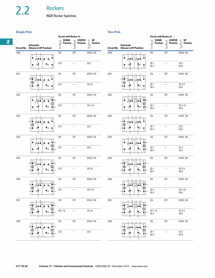
1006 ON OFF MOM. ON
2B-1 — 2B-3
1601 ON OFF MOM. ON
2B-1 — 2B-3-9
1602 ON OFF MOM. ON
2B-1 — 2B-3-10
1603 ON OFF MOM. ON
2B-1 — 2B-3
1604 ON OFF MOM. ON
2B-1 — 2B-3
1605 ON OFF MOM. ON
2B-1 — 2B-3-9
1606 ON OFF MOM. ON
2B-1 — 2B-3-10
1607 ON OFF MOM. ON
2B-1-10 — 2B-3-9
1608 ON OFF MOM. ON
2B-1 — 2B-3
10
4
8
5B
1 63
2B
9
7
8
4
10
5B
1 6
2B
3
7
9
4
10
1 63
9
8
5B2B
7
3 4
10
8
5B
1 6
2B
9
7
10
8
4
5B
1 6
2B
3
9
7
4
10
8
5B
613
2B
9
7
4
10
8
5B
3 1 6
2B
9
7
10
4
8
5B
1 6
2B
3
9
7
4
10
613
8
5B2B
9
7
Circuit with Rocker In …
Circuit No.Schematic(Shown in UP Position)
DOWN Position
CENTER Position
UP Position
2006 ON OFF MOM. ON
2B-15B-4
— 2B-35B-6
2601 ON OFF MOM. ON
2B-15B-4
— 2B-3-95B-6
2602 ON OFF MOM. ON
2B-15B-4
— 2B-3-105B-6
2603 ON OFF MOM. ON
2B-15B-4
— 2B-35B-6
2604 ON OFF MOM. ON
2B-15B-4
— 2B-35B-6
2605 ON OFF MOM. ON
2B-15B-4
— 2B-3-95B-6
2606 ON OFF MOM. ON
2B-15B-4
— 2B-3-105B-6
2607 ON OFF MOM. ON
2B-1-105B-4
— 2B-3-95B-6
2608 ON OFF MOM. ON
2B-15B-4
— 2B-35B-6
10
5B
8
46
9
2B
1
7
3
8
5B
10
46
7
2B
1
9
3
4
10
613
9
5B
8
2B
7
4
10
5B
8
63
9
2B
1
7
10
8
5B
46
9
7
2B
13
4
10
6
5B
8
13
9
2B
7
6 4
10
5B
8
3 1
9
2B
7
10
5B
8
46
9
2B
1
7
3
4
10
6
5B
8
13
9
2B
7

Volume 11—Vehicle and Commercial Controls CA08100013E—December 2015 www.eaton.com V11-T2-23
2
2
2
2
2
2
2
2
2
2
2
2
2
2
2
2
2
2
2
2
2
2
2
2
2
2
2
2
2
2
2.2Rockers
NGR Rocker Switches
Single-Pole Two-Pole
Circuit with Rocker In …
Circuit No.Schematic(Shown in UP Position)
DOWN Position
CENTER Position
UP Position
1007 ON NONE MOM ON
2B-1 — 2B-3
1621 ON NONE MOM ON
2B-1 — 2B-3-9
1622 ON NONE MOM ON
2B-1 — 2B-3-10
1623 ON NONE MOM ON
2B-1 — 2B-3
1624 ON NONE MOM ON
2B-1 — 2B-3
1625 ON NONE MOM ON
2B-1 — 2B-3-9
1626 ON NONE MOM ON
2B-1 — 2B-3-10
1627 ON NONE MOM ON
2B-1-10 — 2B-3-9
1628 ON NONE MOM ON
2B-1 — 2B-3
13 46
7 8
9 10
2B 5B
13 46
7 8
9 10
2B 5B
13 46
7 8
9 10
2B5B
13 46
7 8
9 10
2B 5B
13 46
7 8
9 10
2B 5B
13 46
7 8
9 10
2B 5B
13 46
7 8
9 10
2B 5B
13 46
7 8
9
2B 5B
13 46
7 8
9 10
2B 5B
Circuit with Rocker In …
Circuit No.Schematic(Shown in UP Position)
DOWN Position
CENTER Position
UP Position
2007 ON NONE MOM ON
2B-15B-4
— 2B-35B-6
2621 ON NONE MOM ON
2B-15B-4
— 2B-3-95B-6
2622 ON NONE MOM ON
2B-15B-4
— 2B-3-105B-6
2623 ON NONE MOM ON
2B-15B-4
— 2B-35B-6
2624 ON NONE MOM ON
2B-15B-4
— 2B-35B-6
2625 ON NONE MOM ON
2B-15B-4
— 2B-3-95B-6
2626 ON NONE MOM ON
2B-15B-4
— 2B-3-105B-6
2627 ON NONE MOM ON
2B-1-105B-4
— 2B-3-95B-6
2628 ON NONE MOM ON
2B-15B-4
— 2B-35B-6
13 46
7 8
9 10
2B 5B
13 46
7 8
9 10
2B 5B
13 46
7 8
9 10
2B 5B
13 46
7 8
9 10
2B 5B
13 46
7 8
9 10
2B 5B
13 46
7 8
9 10
2B 5B
13 46
7 8
9 10
2B 5B
13 46
7 8
9 10
2B 5B
13 46
7 8
9 10
2B 5B

V11-T2-24 Volume 11—Vehicle and Commercial Controls CA08100013E—December 2015 www.eaton.com
2
2
2
2
2
2
2
2
2
2
2
2
2
2
2
2
2
2
2
2
2
2
2
2
2
2
2
2
2
2
2.2 Rockers
NGR Rocker Switches
Single-Pole Two-Pole
Circuit with Rocker In …
Circuit No.Schematic(Shown in UP Position)
DOWN Position
CENTER Position
UP Position
3003 OFF ON ON
2A-1 2A-2B 2B-3
3541 OFF ON ON
2A-1 2A-2B 2B-3-9
3542 OFF ON ON
2A-1 2A-2B 2B-3-10
3543 OFF ON ON
2A-1 2A-2B 2B-3
3544 OFF ON ON
2A-1 2A-2B 2B-3
3545 OFF ON ON
2A-1 2A-2B 2B-3-9
3546 OFF ON ON
2A-1 2A-2B 2B-3-10
3547 OFF ON ON
2A-1-10 2A-2B 2B-3-9
3548 OFF ON ON
2A-1 2A-2B 2B-3
10
4
5A 8
61
2B
3
9
7 5B
2A
2A
5B7
9
3
2B
1 6
85A
4
10
2A
5B7
9
3
2B
1 6
85A
4
10
2A
5B7
9
3
2B
1 6
85A
4
10
2A
5B7
9
3
2B
1 6
85A
4
10
2A
5B7
9
3
2B
1 6
85A
4
10
2A
5B7
9
3
2B
1 6
85A
4
10
2A
5B7
9
3
2B
1 6
85A
4
10
2A
5B7
9
3
2B
1 6
85A
4
10
Circuit with Rocker In …
Circuit No.Schematic(Shown in UP Position)
DOWN Position
CENTER Position
UP Position
3004 OFF ON ON
2A-15A-4
2A-2B5A-5B
2B-35B-6
3561 OFF ON ON
2A-15A-4
2A-2B5A-5B
2B-3-95B-6
3562 OFF ON ON
2A-15A-4
2A-2B5A-5B
2B-3-105B-6
3563 OFF ON ON
2A-15A-4
2A-2B5A-5B
2B-35B-6
3564 OFF ON ON
2A-15A-4
2A-2B5A-5B
2B-35B-6
3565 OFF ON ON
2A-15A-4
2A-2B5A-5B
2B-3-95B-6
3566 OFF ON ON
2A-15A-4
2A-2B5A-5B
2B-3-105B-6
3567 OFF ON ON
2A-1-105A-4
2A-2B5A-5B
2B-3-95B-6
3568 OFF ON ON
2A-15A-4
2A-2B5A-5B
2B-35B-6
2A
7
9
3
2B
1 6
8
4
10
5B
5A
10
4
8
61
2B
3
9
7
2A 5A
5B
10
4
8
61
2B
3
9
7
2A 5A
5B
10
4
8
61
2B
3
9
7
2A 5A
5B
10
4
8
61
2B
3
9
7
2A 5A
5B
10
4
8
61
2B
3
9
7
2A 5A
5B
10
4
8
61
2B
3
9
7
2A 5A
5B
10
4
8
61
2B
3
9
7
2A 5A
5B
10
4
8
61
2B
3
9
7
2A 5A
5B

Volume 11—Vehicle and Commercial Controls CA08100013E—December 2015 www.eaton.com V11-T2-25
2
2
2
2
2
2
2
2
2
2
2
2
2
2
2
2
2
2
2
2
2
2
2
2
2
2
2
2
2
2
2.2Rockers
NGR Rocker Switches
Single-Pole Two-Pole
Circuit with Rocker In …
Circuit No.Schematic(Shown in UP Position)
DOWN Position
CENTER Position
UP Position
5001 ON NONE OFF
2B-1 — —
5501 ON NONE OFF
2B-1-9 — —
5502 ON NONE OFF
2B-1-10 — —
5503 ON NONE OFF
2B-1 — —
5504 ON NONE OFF
2B-1 — —
5505 ON NONE OFF
2B-1-9 — —
5506 ON NONE OFF
2B-1-10 — —
5507 ON NONE OFF
2B-1-9-10 — —
5508 ON NONE OFF
2B-1 — —
5B
7
9
2B
3 1 6
8
4
10
5B
7
9
2B
3 1 6
8
4
10
5B
7
3
2B
1 6
9
8
4
10
5B
7
2B
9
3 1 6
8
4
10
5B
7
9
2B
3 1 6
8
4
10
5B
7
9
2B
3 61
8
10
4
5B
7
9
1 6
2B
3
8
4
10
3
2B
61
9
7
10
4
8
5B
5B
7
2B
9
3 61
8
10
4
Circuit with Rocker In …
Circuit No.Schematic(Shown in UP Position)
DOWN Position
CENTER Position
UP Position
5510 ON NONE OFF
2B-15B-4
— —
5511 ON NONE OFF
2B-1-95B-4
— —
5512 ON NONE OFF
2B-1-105B-4
— —
5513 ON NONE OFF
2B-15B-4
— —
5514 ON NONE OFF
2B-15B-4
— —
5515 ON NONE OFF
2B-1-95B-4
— —
5516 ON NONE OFF
2B-1-105B-4
— —
5517 ON NONE OFF
2B-1-9-105B-4
— —
5518 ON NONE OFF
2B-15B-4
— —
2B
7 8
5B
3
9 10
461
87
3
2B
9 10
461
5B
9
2B
3
7
10
4
8
61
5B
3
9
2B
7
10
4
8
61
5B
3
2B
7
4
8
61
5B
9 10
2B
7 8
5B
3
9
4
10
1 6
87
3
2B
9 10
461
5B
7
9
2B
3
5B
8
4
10
1 6
3
9
2B
7
4
10
8
1 6
5B

V11-T2-26 Volume 11—Vehicle and Commercial Controls CA08100013E—December 2015 www.eaton.com
2
2
2
2
2
2
2
2
2
2
2
2
2
2
2
2
2
2
2
2
2
2
2
2
2
2
2
2
2
2
2.2 Rockers
NGR Rocker Switches
Single-Pole
Circuit with Rocker In …
Circuit No.Schematic(Shown in UP Position)
DOWN Position
CENTER Position
UP Position
5002 MOM. ON NONE OFF
2B-1 — —
5521 MOM. ON NONE OFF
2B-1-9 — —
5522 MOM. ON NONE OFF
2B-1-10 — —
5523 MOM. ON NONE OFF
2B-1 — —
5524 MOM. ON NONE OFF
2B-1 — —
5525 MOM. ON NONE OFF
2B-1-9 — —
5526 MOM. ON NONE OFF
2B-1-10 — —
5528 MOM. ON NONE OFF
2B-1 — —
2B
7
9
3
5B
1 6 4
8
10
7
9
3
2B 5B
1 6 4
8
10
7
3
2B 5B
1 6 4
8
9 10
7
2B 5B
8
9
3 1 6 4
10
3
7
2B
9
4
5B
1 6
10
8
2B
7
9
3
5B
1 6 4
8
10
7
9
3
2B 5B
1 6 4
8
10
7
2B 5B
8
9
3 1 6 4
10
Circuit with Rocker In …
Circuit No.Schematic(Shown in UP Position)
DOWN Position
CENTER Position
UP Position
5003 ON ON OFF
2A-1 2A-2B 2B-3
5541 ON ON OFF
2A-1 2A-2B 2B-3-9
5542 ON ON OFF
2A-1 2A-2B 2B-3-10
5543 ON ON OFF
2A-1 2A-2B 2B-3
5544 ON ON OFF
2A-1 2A-2B 2B-3
5545 ON ON OFF
2A-1 2A-2B 2B-3-9
5546 ON ON OFF
2A-1 2A-2B 2B-3-10
5547 ON ON OFF
2A-1-10 2A-2B 2B-3-9
5548 ON ON OFF
2A-1 2A-2B 2B-3
5A
9
7
61
5B2B
3
2A
10
4
8
5A7
9
5B
1 63
2B
2A
8
4
10
5A
9
7
1 6
5B
3
2B
2A
4
10
8
5A7
1 6
5B
3
2B
2A
9
4
8
10
5A7 5B2B
9
1 63
2A
8
4
10
5A7
9
5B
1 63
2B
2A
8
4
10
5A7
9
5B
1 63
2B
2A
8
4
10
5A
9
7
1 6
5B
3
2B
2A
4
10
8
5A
9
7
1 6
5B
3
2B
2A
4
10
8

Volume 11—Vehicle and Commercial Controls CA08100013E—December 2015 www.eaton.com V11-T2-27
2
2
2
2
2
2
2
2
2
2
2
2
2
2
2
2
2
2
2
2
2
2
2
2
2
2
2
2
2
2
2.2Rockers
NGR Rocker Switches
Two-Pole
Circuit with Rocker In …
Circuit No.Schematic(Shown in UP Position)
DOWN Position
CENTER Position
UP Position
3001 ON ON ON
5B-4-2B-1 5B-4-2B-3 2B-35B-6
3501 ON ON ON
5B-4-2B-1 5B-4-2B-3-9 2B-3-95B-6
3502 ON ON ON
5B-4-2B-1 5B-4-2B-3-10 2B-3-105B-6
3503 ON ON ON
5B-4-2B-1 5B-4-2B-3 2B-35B-6
3504 ON ON ON
5B-4-2B-1 5B-4-2B-3 2B-35B-6
3505 ON ON ON
5B-4-2B-1 5B-4-2B-3 2B-35B-6
3506 ON ON ON
5B-4-2B-1 5B-4-2B-3 2B-35B-6
3507 ON ON ON
5B-4-2B-1 5B-4-2B-3-9 2B-3-95B-6
3508 ON ON ON
5B-4-2B-1 5B-4-2B-3 2B-35B-6
9
7
4
2B
3 1 6
5B
10
8
7
2B
8
5B
9
1 63
10
4
7
9
1 6
2B
3
8
10
5B
4
7
43
2B 5B
61
8
9 10
9
7
43
2B 5B
61
10
8
10
8
5B
4613
2B
7
9
10
8
5B
461
2B
3
7
9
1 63 4
2B 5B
10
87
9
9
7
43
2B 5B
61
10
8
Circuit with Rocker In …
Circuit No.Schematic(Shown in UP Position)
DOWN Position
CENTER Position
UP Position
3002 OFF 1–ON 2–ON
2B-15B-4
2B-35B-4
2B-35B-6
3521 OFF 1–ON 2–ON
2B-15B-4
2B-3-95B-4
2B-3-95B-6
3522 OFF 1–ON 2–ON
2B-15B-4
2B-3-105B-4
2B-3-105B-6
3523 OFF 1–ON 2–ON
2B-15B-4
2B-35B-4
2B-35B-6
3524 OFF 1–ON 2–ON
2B-15B-4
2B-35B-4
2B-35B-6
3525 OFF 1–ON 2–ON
2B-15B-4
2B-3-95B-4
2B-3-95B-6
3526 OFF 1–ON 2–ON
2B-15B-4
2B-3-105B-4
2B-3-105B-6
3527 OFF 1–ON 2–ON
2B-1-105B-4
2B-3-95B-4
2B-3-95B-6
3528 OFF 1–ON 2–ON
2B-15B-4
2B-35B-4
2B-35B-6
3 1
9
2B
7
4
10
6
5B
8
2B 5B
3 461
8
10
7
9
2B
7
9
3
8
4
5B
61
10
2B
3 1
9
7
4
5B
10
6
8
13
2B
9
7
4
10
6
5B
8
9
3
7
2B
61 4
5B
8
10
2B
7
13
9
5B
8
10
46
9
3
7
2B
6 4
10
8
5B
1
3 1
2B
9
7
4
10
6
5B
8

V11-T2-28 Volume 11—Vehicle and Commercial Controls CA08100013E—December 2015 www.eaton.com
2
2
2
2
2
2
2
2
2
2
2
2
2
2
2
2
2
2
2
2
2
2
2
2
2
2
2
2
2
2
2.2 Rockers
NGR Rocker Switches
Two-Pole
Circuit with Rocker In …
Circuit No.Schematic(Shown in UP Position)
DOWN Position
CENTER Position
UP Position
3005 MOM. ON ON MOM. ON
2B-15B-4
2B-15B-6
2B-35B-6
3581 MOM. ON ON MOM. ON
2B-15B-4
2B-15B-6
2B-3-95B-6
3582 MOM. ON ON MOM. ON
2B-15B-4
2B-15B-6
2B-3-105B-6
3583 MOM. ON ON MOM. ON
2B-15B-4
2B-15B-6
2B-35B-6
3584 MOM. ON ON MOM. ON
2B-15B-4
2B-15B-6
2B-35B-6
3585 MOM. ON ON MOM. ON
2B-15B-4
2B-15B-6
2B-3-95B-6
3586 MOM. ON ON MOM. ON
2B-15B-4
2B-15B-6
2B-3-105B-6
3587 MOM. ON ON MOM. ON
2B-1-105B-4
2B-1-105B-6
2B-3-95B-6
3588 MOM. ON ON MOM. ON
2B-15B-4
2B-15B-6
2B-35B-6
1
2B
3
7
9
8
5B
4
10
6
13
2B
9
7
6
10
4
5B
8
1
9
3
2B
7
10
6 4
5B
8
3 1 6 4
2B
7 8
5B
9 10
1
2B
7
3
9
8
5B
10
46
13
2B
9
7
6
10
4
5B
8
13
2B
7
9
6
10
4
5B
8
13
2B
9
7
6 4
5B
10
8
1
2B
3
7 8
4
5B
6
9 10
Circuit with Rocker In …
Circuit No.Schematic(Shown in UP Position)
DOWN Position
CENTER Position
UP Position
4001 NONE ON MOM. ON
2B-15B-4
2B-15B-4
2B-35B-6
4501 NONE ON MOM. ON
2B-15B-4
2B-15B-4
2B-3-95B-6
4502 NONE ON MOM. ON
2B-15B-4
2B-15B-4
2B-3-105B-6
4503 NONE ON MOM. ON
2B-15B-4
2B-15B-4
2B-35B-6
4504 NONE ON MOM. ON
2B-15B-4
2B-15B-4
2B-35B-6
4505 NONE ON MOM. ON
2B-15B-4
2B-15B-4
2B-3-95B-6
4506 NONE ON MOM. ON
2B-15B-4
2B-15B-4
2B-3-105B-6
4507 NONE ON MOM. ON
2B-1-105B-4
2B-1-105B-4
2B-3-95B-6
4508 NONE ON MOM. ON
2B-15B-4
2B-15B-4
2B-35B-6
87
2B
9
5B
41
10
63
9
7
3 61
2B
10
4
5B
8
9
7
3 61
2B
10
4
5B
8
7
9
8
10
2B
3 1 6 4
5B
7
9
8
10
2B
1 4
5B
63
9
7
3 61
2B
10
4
5B
8
3 61
2B
10
4
5B
87
9
3 61
2B
4
5B
9
7
10
8
7 8
9 10
2B
1 4
5B
63

Volume 11—Vehicle and Commercial Controls CA08100013E—December 2015 www.eaton.com V11-T2-29
2
2
2
2
2
2
2
2
2
2
2
2
2
2
2
2
2
2
2
2
2
2
2
2
2
2
2
2
2
2
2.2Rockers
NGR Rocker Switches
Two-Pole
Circuit with Rocker In …
Circuit No.Schematic(Shown in UP Position)
DOWN Position
CENTER Position
UP Position
5004 ON ON OFF
2A-15A-4
2A-2B5A-5B
2B-35B-6
5561 ON ON OFF
2A-15A-4
2A-2B5A-5B
2B-3-95B-6
5562 ON ON OFF
2A-15A-4
2A-2B5A-5B
2B-3-105B-6
5563 ON ON OFF
2A-15A-4
2A-2B5A-5B
2B-35B-6
5564 ON ON OFF
2A-15A-4
2A-2B5A-5B
2B-35B-6
5565 ON ON OFF
2A-15A-4
2A-2B5A-5B
2B-3-95B-6
5566 ON ON OFF
2A-15A-4
2A-2B5A-5B
2B-3-105B-6
5567 ON ON OFF
2A-1-105A-4
2A-2B5A-5B
2B-3-95B-6
5568 ON ON OFF
2A-15A-4
2A-2B5A-5B
2B-35B-6
2B
3
9
7
5A
5B
10
4
8
61
2A
7
9
3
2B 5B
5A2A
1 6
8
4
10
7
9
3
2B 5B
5A2A
1 6
8
4
10
7
3
2B 5B
5A2A
1 6
8
4
9 10
7
2B 5B
8
9
3
5A2A
1 6 4
10
7
9
3
2B 5B
5A2A
1 6
8
4
10
7
9
3
2B 5B
5A2A
1 6
8
4
10
7
9
3
2B 5B
5A2A
1 6
8
4
10
7
3
2B 5B
5A2A
1 6
8
4
9 10
Circuit with Rocker In …
Circuit No.Schematic(Shown in UP Position)
DOWN Position
CENTER Position
UP Position
5005 2–ON 1–ON OFF
2B-15B-4
2B-35B-4
2B-35B-6
5581 2–ON 1–ON OFF
2B-15B-4
2B-3-95B-4
2B-3-95B-6
5582 2–ON 1–ON OFF
2B-15B-4
2B-3-105B-4
2B-3-105B-6
5583 2–ON 1–ON OFF
2B-15B-4
2B-35B-4
2B-35B-6
5584 2–ON 1–ON OFF
2B-15B-4
2B-35B-4
2B-35B-6
5585 2–ON 1–ON OFF
2B-15B-4
2B-3-95B-4
2B-3-95B-6
5586 2–ON 1–ON OFF
2B-15B-4
2B-3-105B-4
2B-3-105B-6
5587 2–ON 1–ON OFF
2B-1-105B-4
2B-3-95B-4
2B-3-95B-6
5588 2–ON 1–ON OFF
2B-15B-4
2B-35B-4
2B-3-95B-6
6001 ON NONE ON
2A-2B-5A-5B-10-1-4-3
— 3-6-1
7
2B
9
3
8
5B
6
10
41
7
3
2B
9
8
1 6 4
5B
10
7
2B 5B
8
3
9 10
1 6 4
7
9
3
2B
8
6
10
5B
41
7
9
2B
3
8
5B
6
10
41
2B
7
3
9 10
8
5B
41 6
3
7
2B
9
6 4
8
5B
1
10
2B
7
5B
8
3
9
1
10
46
7
9
2B
3
8
5B
6
10
41
7 2B2A3 1
96 4 5B5A
8
10

V11-T2-30 Volume 11—Vehicle and Commercial Controls CA08100013E—December 2015 www.eaton.com
2
2
2
2
2
2
2
2
2
2
2
2
2
2
2
2
2
2
2
2
2
2
2
2
2
2
2
2
2
2
2.2 Rockers
NGR Rocker Switches
DimensionsApproximate Dimensions in Inches (mm)
Switch Base with Rocker Button
0.523 ± 0.005
(13.28 ± 0.13)
0.257 ± 0.005
(6.53 ± 0.13)
1.800 Max.
(45.42 Max.)
0.667 ± 0.005
(16.94 ± 0.13)
0.401 ± 0.005
(10.19 ± 0.13)
41
79
8
2B
2A
USA
3
10
5B
5A 6
0.855 ± 0.010
(21.72 ± 0.25)
0.462 ± 0.005
(11.73 ± 0.13)
0.100 ± 0.005
(2.54 ± 0.13)
1.970 ± 0.010
(50.04 ± 0.25)
1.024 ± .010
(26.01 ± 0.25)
C
BA
0.867 ± 0.005
(22.02 ± 0.13)
1.734 ± 0.005
(44.04 ± 0.13) Panel Opening
Panel Thickness:
0.039 to 0.157 in
(1.00 to 4.00) mm
(Best results
obtained between
0.059 and 0.118 in
[1.50 and 3.00 mm])
0.054 ± 0.005
(1.37 ± 0.13)
0.500 ± 0.010
(12.70 ± 0.25)
AR
EA
“B
”
LE
GE
ND
On Indicator “A” On Indicator “B”
7 4 5A 5B 6 8
1032B2A19
0.250 ± 0.005
(6.35 ± 0.13)
0.408 ± 0.010
(10.36 ± 0.25)
0.345 ± 0.010
(8.76 ± 0.25)
1.970 ± 0.010
(50.04 ± 0.25)
1.024 ± 0.010
(26.01 ± 0.25)
0.500 Max.
(12.70 Max.)
0.320 Max.
(8.13 Max.)
0.500 Max.
(12.70 Max.)
ROADLAMP
Orientation
Examples of “Standard”
Orientation of Icons
0.144 ± 0.005
(3.66 ± 0.13)
Terminals
8 and 10
Terminals
7 and 9
Decorative
Rocker
SIL Rocker
(Snap-In Lens)
AR
EA
“A
”
LE
GE
ND
AR
EA
“B
”
LE
GE
ND
AR
EA
“A
”
LE
GE
ND
0.320 Max.
(8.13 Max.)
0.0305/0.032
(0.775/0.813)

Volume 11—Vehicle and Commercial Controls CA08100013E—December 2015 www.eaton.com V11-T2-31
2
2
2
2
2
2
2
2
2
2
2
2
2
2
2
2
2
2
2
2
2
2
2
2
2
2
2
2
2
2
2.2Rockers
NGR Rocker Switches
Approximate Dimensions in Inches (mm)
Locking Rocker
Indicator
Sealed Rocker
Label Rocker
AB
C
LE
GE
ND
0.345 ± 0.010
(8.76 ± 0.25)
AR
EA
“B
”
0.245 ± 0.005
(6.22 ± 0.13)
0.320 ± 0.005 Max.
(8.13 ± 0.13 Max.)
1.970 ± 0.010
(50.04 ± 0.25)
1.024 ± 0.010
(26.0 ± 0.25)0.500 ± 0.005 Max.
(12.70 ± 0.13 Max.)
1.800 Max.
(45.42 Max.)
0.100 ± 0.005
(2.54 ± 0.13)
0.408 ± 0.010
(10.36 ± 0.25)
1.970 ± 0.010
(50.04 ± 0.25)
1.800 Max.
(45.42 Max.)
0.100 ± 0.005
(2.54 ± 0.13)
1.024 ± 0.010
(26.01 ± 0.25)
0.095 ± 0.005
(2.42 ± 0.13)
0.500 Max.
(12.70 Max.)
0.320 Max.
(8.13 Max.)
0.408 ± 0.010
(10.36 ± 0.25)
LE
GE
ND
AR
EA
“A
”
LE
GE
ND
AR
EA
“B
”
0.0305/0.032
(0.775/0.813)
C
AB
1.450 ± 0.040
(36.83 ± 1.02)
0.060 ± 0.010
(1.52 ± 0.25)
Panel Seal
1.970 ± 0.010
(50.04 ± 0.25)
1.024 ± 0.010
(26.01 ± 0.25)
0.500 Max.
(12.70 Max.)
0.320 Max.
(8.13 Max.)
0.408 ± 0.010
(10.36 ± 0.25)
0.345 ± 0.010
(8.76 ± 0.25)
0.420 ± 0.005
(10.67 ± 0.13)
LE
GE
ND
AR
EA
“A
”
LE
GE
ND
AR
EA
“B
”
12° ± 1°
0.580 ± 0.008
(14.73 ± 0.020)
1.128 ± 0.010
(28.65 ± 0.25)
0.020 ± 0.005
(5.08 ± 0.13)
R0.060 ± 0.005
(R1.52 ± 0.13)
0.470 ± 0.010
(11.94 ± 0.25)
0.375 ± 0.010
(9.53 ± 0.25)
Surface Length Along Bottom
Note: Graphics window may be on both ends or either end of part.
Dimensions shown are typical.
Rotated 12° CCW
Graphics Window

V11-T2-32 Volume 11—Vehicle and Commercial Controls CA08100013E—December 2015 www.eaton.com
2
2
2
2
2
2
2
2
2
2
2
2
2
2
2
2
2
2
2
2
2
2
2
2
2
2
2
2
2
2
2.3 Rockers
SVR—Sealed Vehicle Rockers
SVR—Sealed Vehicle Rocker ContentsDescription Page
SVR—Sealed Vehicle Rockers Above-Panel Rocker Switch . . . . . . . . . . . . . . . V11-T2-34
Below-Panel Rocker Switch . . . . . . . . . . . . . . . V11-T2-35
Technical Data and Specifications . . . . . . . . . . V11-T2-36
Circuit Diagrams . . . . . . . . . . . . . . . . . . . . . . . . V11-T2-37
Dimensions . . . . . . . . . . . . . . . . . . . . . . . . . . . V11-T2-38
Product DescriptionThe Sealed Vehicle Rocker (SVR) switch from Eaton’s electrical business now offers an above panel actuator style in addition to the below panel and paddle actuators. Designed to meet the severe environmental requirements of the construction and agricultural vehicle markets, the SVR is sealed at the front and back of the switch and meets the rigorous sealing requirements of IP68.
The small switch footprint minimizes the space taken on switch panels. SVR switches are assembled into panels by pressing the switch through the top of the panel and are held in place by retention tabs molded into the body of the switch; mounting hardware or special tools are not necessary.
The SVR is offered in single- and two-pole switch circuits, with two- and three-position momentary and maintained circuits available. Switch and illumination circuits are terminated with 0.11 in (2.8 mm) tin-plated copper alloy spade terminals. The SVR connector can be loaded with the appropriate terminals and/or wire seals to accomplish sealing at the back end of the switch.
FeaturesYou can order assembled switches or the switch base and actuator separately.
Use the final code in the switch base catalog number, Pages V11-T2-34 andV11-T2-35, to denote assembly instructions.
Actuator The SVR switch family includes three styles of actuators: above panel, below panel and paddle.
Switch performance and specifications are the same for all actuator styles. Black is standard, but other colors are also available. Matte finish is standard on all actuator styles, matching the finish on the bezels and all other visible SVR switch features and accessories.
Actuator Styles● Above panel rocker button
offers new styling and a larger surface area. Eaton can offer assistance with unique designs of above panel actuators for applications where differentiation is desired
● Below panel rocker button is the same two-faced European styling that has been offered for SVR since its initial release. Indicator style matches the below panel rocker button style
● Paddle actuator allows toggle-type actuation of the SVR switch
Standards and Certifications● Approvable under stringent
UL and CSA standards● For information, contact
your local Eaton Sales Representative
● RoHS Compliant 1
Note1 Visit www.eaton.com/vcbu for
the most up-to-date list of verified part numbers.

Volume 11—Vehicle and Commercial Controls CA08100013E—December 2015 www.eaton.com V11-T2-33
2
2
2
2
2
2
2
2
2
2
2
2
2
2
2
2
2
2
2
2
2
2
2
2
2
2
2
2
2
2
2.3Rockers
SVR—Sealed Vehicle Rockers
IlluminationLong life LEDs provide backlighting illumination for the SVR switch. Backlighting can be either independent of or dependent on the switch circuits, or a combination of both. Standard LED color is amber, with red, green and blue also available. LED protection circuitry is available to protect the LED from overvoltage and reverse voltage conditions.
Contact your local Eaton Sales Representative for more specific information about standard and custom circuit options.
Backlighting● Each switch can
accommodate up to two LEDs that can be connected to be either circuit dependent or independent
● Standard LED color is amber, with red, green and blue also available. Long life (100,000 hours) LEDs are standard
● Standard LED voltages are 12 and 24 Vdc
● The below panel rocker button style includes a single-piece back-lit actuator with laser-etched icons in either daylight white or deadfront styles. Without illumination, the icon is either daylight white or deadfront, but will change to the color of the chosen light source when illuminated
Snap-in Lenses● Above and below panel
rocker buttons are available with or without one or two translucent lenses. Five standard lens colors are available: white, red, green, blue and amber
Icons● Icon areas are provided
on each end of the rocker button. Icons may be illuminated or non-illuminated and are pad-printed in a contrasting color either directly on the rocker button or the lens
Mounting MeansSnap-in mounting using four flexible plastic retainers integral with switch frame.
CircuitsThe SVR switch is capable of single- or two-pole configurations with two- or three-position maintained, momentary or a combination of actuations.
The addition of jumpers between switch terminals expands the circuit possibilities.
Contact your local Eaton Sales Representative for more specific information about SVR standard and custom circuit options.
Standard Circuit Options● ON–NONE–ON● ON–OFF–ON● ON*–OFF–ON*● ON*–OFF–ON● ON–ON–ON● ON*–NONE–ON● ON*–ON–ON*● ON*–ON–ON
Note: * = Momentary. See Electrical Circuit Diagrams on Page V11-T2-37.
SealingSVR design includes a sealed contact chamber with dust and water resistance to IP68. The harness connection can also be sealed by using AMP wire seals Catalog Number 828905-1 (14–16 gauge) or 828904-1 (18–20 gauge) to seal the wires to the connector. For an application where a connector cavity is not being used, it can be sealed with AMP sealing plug Catalog Number 828922-1.
The above panel version may also be sealed to the panel using panel seal Catalog Number 32-2245.
Options● Additional colors of
actuators, mounting bezels and lenses
● Special circuits● Special ratings● Pad printing on the below
panel switch bezel● Low current capabilities● Custom back-lit icons● Gang-mount system
including end bezel Catalog Number 17-22146 and center bezel 17-22152
● Palm Guard (below panel switch only) at either or both ends of the switch frame
● Indicators with insertable lenses
● Polarized lock-on connector Catalog Number 25-13936
● Panel plug with connector retention feature Catalog Number 17-22145
● Non-illuminated below panel paddle actuator
Note: Contact your local Eaton Sales Representative for additional information on options.

V11-T2-34 Volume 11—Vehicle and Commercial Controls CA08100013E—December 2015 www.eaton.com
2
2
2
2
2
2
2
2
2
2
2
2
2
2
2
2
2
2
2
2
2
2
2
2
2
2
2
2
2
2
2.3 Rockers
SVR—Sealed Vehicle Rockers
Above-Panel Rocker Switch
Catalog Number SelectionHow To Order—Above-Panel SVR Switch
Notes1 Gold plated.2 Two-pole only. See Electrical Circuit Diagrams on Page V11-T2-37 and Illumination Circuit Diagrams on Page V11-T2-38.3 For red rocker, only actuator style options A, C and F are available.
Lens Color (Bottom/Right)X = NoneR = RedG = Green
B = BlueA = Amber
W = WhiteDecorative Icon Color
X = No icon1 = Daylight white2 = Deadfront
Icon (Bottom/Right)XX = NoneAV = HazardSee Symbols Library on Pages V11-T2-82 to V11-T2-86 and V11-T2-97 to V11-T2-104.
To determine complete catalog number, start with the appropriate switch series and add the appropriate code letters and/or numbers.
S A C M 2 X D G A T R A V X X
Switch Series
S = SVR
LED (Top/Left)1st Digit
X = None14V Standard
J = RedK = GreenL = Amber (standard for lensed rockers)
M = BlueN = White (standard for decorative rockers)
14V Over/Reverse Voltage Protection1 = Red2 = Green3 = Amber (standard)7 = Blue
28V StandardE = RedF = GreenG = Amber (standard for lensed rockers)H = BlueP = White (standard for decorative rockers)
28V Over/Reverse Voltage Protection4 = Red5 = Green6 = Amber (standard)8 = Blue
Example:
KEY: * = Momentary, (I) = Independent, (D) = Dependent.
Switch Circuits/Illumination Circuits
1st Digit (Circuit)2nd Digit (Illumination)
Single-Pole Illumination
A = ON–NONE–ONC = ON–NONE–ON 1D = ON–OFF–ONE = ON–OFF–ON 1F = ON*–OFF–ON*G = ON*–OFF–ON* 1H = ON*–OFF–ONJ = ON*–OFF–ON 1K = ON–ON–ON 2L = ON–ON–ON 12
M = ON*–NONE–ONP = ON*–NONE–ON 1R = ON*–ON–ON* 2S = ON*–ON–ON* 12
T = ON*–ON–ONU = ON*–ON–ON 1
A = NoneC = Top/left (D)D = Bottom/right (D)E = Top/left (I)F = Bottom/right (I)G = Top/left (D)/bottom/right (I)H = Top/left (I)/bottom/right (D)J = Top/left (D)/bottom/right (D)K = Top/left (I)/bottom/right (I)
Two-Pole IlluminationR = NoneS = Top/left (D)T = Bottom/right (D)U = Top/left (I)V = Bottom/right (I)
W = Top/left (D)/bottom/right (I)Y = Top/left (I)/bottom/right (D)3 = Top/left (D)/bottom/right (D)4 = Top/left (I)/bottom/right (I)
LED Wavelengths: Red = ~630 NmAmber = ~592 NmGreen = ~526 NmBlue = ~472 Nm
White LED Coordinates: White = 0.31 x 0.31
LED (Bottom/Right)2nd Digit
X = NoneSame codes available as 1st digit.
Lens Color (Top/Left)X = NoneR = RedG = Green
B = BlueA = Amber
W = WhiteDecorative Icon Color
X = No icon1 = Daylight white
Icon (Top/Left)XX = NoneAT = Work light
See Symbols Library on Pages V11-T2-82 to V11-T2-86 and V11-T2-97 to V11-T2-104.
Special Feature
X = NoneFor Eaton use only.
Frame
M = Standard
Actuator StyleA = Decorative rockerC = No lensD = Top/left lens onlyE = Bottom/right lens onlyF = Top/left and
Bottom/right lenses
Rocker Color
X = BlackR = Red 3

Volume 11—Vehicle and Commercial Controls CA08100013E—December 2015 www.eaton.com V11-T2-35
2
2
2
2
2
2
2
2
2
2
2
2
2
2
2
2
2
2
2
2
2
2
2
2
2
2
2
2
2
2
2.3Rockers
SVR—Sealed Vehicle Rockers
Below-Panel Rocker Switch
Catalog Number SelectionHow To Order—Below-Panel Rocker Switch
Notes1 Gold plated.2 Two-pole only. See Electrical Circuit Diagrams on Page V11-T2-37 and Illumination Circuit Diagrams on Page V11-T2-38.
KEY: * = Momentary, (I) = Independent, (D) = Dependent.
Switch Circuits/Illumination Circuits
1st Digit (Circuit)2nd Digit (Illumination)
Single-Pole Illumination
A = ON–NONE–ONC = ON–NONE–ON 1D = ON–OFF–ONE = ON–OFF–ON 1F = ON*–OFF–ON*G = ON*–OFF–ON* 1H = ON*–OFF–ONJ = ON*–OFF–ON 1K = ON–ON–ON 2L = ON–ON–ON 12
M = ON*–NONE–ONP = ON*–NONE–ON 1R = ON*–ON–ON* 2S = ON*–ON–ON* 12
T = ON*–ON–ONU = ON*–ON–ON 1
A = NoneC = Top/left (D)D = Bottom/right (D)E = Top/left (I)F = Bottom/right (I)G = Top/left (D)/bottom/right (I)H = Top/left (I)/bottom/right (D)J = Top/left (D)/bottom/right (D)K = Top/left (I)/bottom/right (I)
Two-Pole IlluminationR = NoneS = Top/left (D)T = Bottom/right (D)U = Top/left (I)V = Bottom/right (I)
W = Top/left (D)/bottom/right (I)Y = Top/left (I)/bottom/right (D)3 = Top/left (D)/bottom/right (D)4 = Top/left (I)/bottom/right (I)
1st and 2nd Digit IndicatorsNE = 7–9 IlluminationNF = 8–10 IlluminationNK = Dual IlluminationN9 = Dual Illumination with 8–9 jumper Lens Color (Bottom/Right)
X = NoneR = RedG = Green
B = BlueA = Amber
W = WhiteDecorative Icon Color
1 = Daylight white2 = Deadfront
To determine complete catalog number, start with the appropriate switch series and add the appropriate code letters and/or numbers.
S A C S 2 X 3 G A T R A C X X
Switch Series
S = SVR
LED (Top/Left)1st Digit
X = None14V Standard
J = RedK = GreenL = Amber (standard)
M = Blue14V Over/Reverse Voltage Protection
1 = Red2 = Green3 = Amber (standard)7 = Blue
28V StandardE = RedF = GreenG = Amber (standard)H = Blue
28V Over/Reverse Voltage Protection4 = Red5 = Green6 = Amber (standard)8 = Blue
Example:
LED Wavelengths: Red = ~630 NmAmber = ~592 NmGreen = ~526 NmBlue = ~472 Nm
LED (Bottom/Right)2nd Digit
X = NoneSame codes available as 1st digit.
Lens Color (Top/Left)X = NoneR = RedG = Green
B = BlueA = Amber
W = WhiteDecorative Icon Color
1 = Daylight white2 = Deadfront
Icon (Top/Left)XX = NoneAT = Work light
See Symbols Library on Pages V11-T2-82 to V11-T2-86 and V11-T2-97 to V11-T2-104.
Special FeatureX = None
For Eaton use only.
Icon (Bottom/Right)XX = NoneAC = FastSee Symbols Library on Pages V11-T2-82 to V11-T2-86 and V11-T2-97 to V11-T2-104.
FrameS = Standard—Below panelT = Palm Guard—Top/leftB = Palm Guard—Bottom/rightF = Palm Guard—Full
Actuator Style1 = No lens2 = Top/left lens only3 = Bottom/right lens only4 = Top/left and bottom/right lenses5 = Paddle—No lens6 = Indicator—Top/left lens7 = Indicator—Bottom/right lens8 = Indicator—Top/left and Bottom/
right lens9 = Indicator—No lensA = Decorative rocker
Special Feature
X = NoneFor Eaton use only.
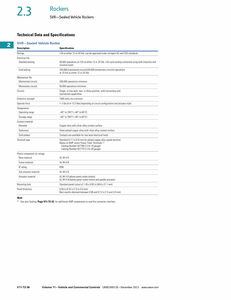
V11-T2-36 Volume 11—Vehicle and Commercial Controls CA08100013E—December 2015 www.eaton.com
2
2
2
2
2
2
2
2
2
2
2
2
2
2
2
2
2
2
2
2
2
2
2
2
2
2
2
2
2
2
2.3 Rockers
SVR—Sealed Vehicle Rockers
Technical Data and Specifications
SVR—Sealed Vehicle Rocker
Note1 See also Sealing, Page V11-T2-33, for additional AMP components to seal the connector interface.
Description Specification
Ratings 12A at either 12 or 24 Vdc, can be approved under stringent UL and CSA standards
Electrical life
Standard plating 50,000 operations at 12A at either 12 or 24 Vdc. Life cycle testing conducted using both inductive and resistive loads
Gold plating 250,000 (maintained circuits)/50,000 (momentary circuits) operations at 10 mA at either 12 or 24 Vdc
Mechanical life
Maintained circuits 250,000 operations minimum
Momentary circuits 50,000 operations minimum
Circuits Single- or two-pole, two- or three-position, with momentary and maintained capabilities
Dielectric strength 1500 volts rms minimum
Operate force 1–3 lbs (4.4–13.2 Nm) depending on circuit configuration and actuator style
Temperature
Operating range –40° to 185°F (–40° to 85°C)
Storage range –40° to 185°F (–40° to 85°C)
Contact material
Movable Copper alloy with silver alloy contact surface
Stationary Silver-plated copper alloy with silver alloy contact surface
Gold-plated Contacts are available for low level electrical loads
Terminal type Standard 0.11 in (2.8 mm) tin-plated copper alloy spade terminalMates to AMP Junior Power Timer Terminals 1 Catalog Number 927766-3 (14–16 gauge) Catalog Number 927770-3 (18–20 gauge)
Plastic component UL ratings
Base material UL 94 V-O
Frame material UL 94 H-B
IP rating IP68
Sub-actuator material UL 94 V-O
Actuator material UL 94 V-0 (above panel rocker button)UL 94 H-B (below panel rocker button and paddle actuator)
Mounting hole Standard panel cutout of 1.45 x 0.83 in (36.8 x 21.1 mm)
Panel thickness 0.04 to 0.16 in (1.0 to 4.0 mm)Best results obtained between 0.06 and 0.12 in (1.5 and 3.0 mm)

Volume 11—Vehicle and Commercial Controls CA08100013E—December 2015 www.eaton.com V11-T2-37
2
2
2
2
2
2
2
2
2
2
2
2
2
2
2
2
2
2
2
2
2
2
2
2
2
2
2
2
2
2
2.3Rockers
SVR—Sealed Vehicle Rockers
Circuit DiagramsSwitch Circuit Schematics
Code
Single-Pole Schematic(Shown in Top/left Actuated Position)
TOP/LEFTActuated
CENTER BOTTOM/RIGHTActuated
AC (Gold)
ON NONE ON
2–3 — 2–1
DE (Gold)
ON OFF ON
2–3 — 2–1
FG (Gold)
MOM. ON OFF MOM. ON
2–3 — 2–1
HJ (Gold)
MOM. ON OFF ON
2–3 — 2–1
KL (Gold)
Two-pole only
MP (Gold)
MOM. ON NONE ON
2–3 — 2–1
RS (Gold)
Two-pole only
TU (Gold)
MOM. ON ON ON
2–3 2–1 2–1
108
9
164
5
72 3
108
9
16
45
72 3
97
2 3
16
410
5
8
972 3
164
5
108
972
3
1
64
5
108
972 3
1
64
5
108
Code
Two-Pole Schematic(Shown in Top/left Actuated Position)
TOP/LEFTActuated
CENTER BOTTOM/RIGHTActuated
AC (Gold)
ON NONE ON
2–35–6
——
2–15–4
DE (Gold)
ON OFF ON
2–35–6
——
2–15–4
FG (Gold)
MOM. ON OFF MOM. ON
2–35–6
——
2–15–4
HJ (Gold)
MOM. ON OFF ON
2–35–6
——
2–15–4
KL (Gold)
ON ON ON
2–35–6
5–4–2–3 5–4–2–1
MP (Gold)
MOM. ON NONE ON
2–35–6
——
2–15–4
RS (Gold)
MOM. ON ON MOM. ON
2–35–6
5–4–2–3 5–4–2–1
TU (Gold)
MOM. ON ON ON
2–35–6
2–15–4
2–15–4
3
8 10
16
45
27 9
16
48
5
10
37
2
9
16
45
8 10
32
7 9
6
45
8 10
3
1
7
2
9
932
7
16
5 4108
8 10
3
16
4
2
5
7 9
932
7
16
5 4108
16
45
8 10
37
2
9

V11-T2-38 Volume 11—Vehicle and Commercial Controls CA08100013E—December 2015 www.eaton.com
2
2
2
2
2
2
2
2
2
2
2
2
2
2
2
2
2
2
2
2
2
2
2
2
2
2
2
2
2
2
2.3 Rockers
SVR—Sealed Vehicle Rockers
Illumination Schematics
Note1 LED for terminals 7–9 is at
top/left side of switch.LED for terminals 8–10 is at bottom/right of switch.
Single- PoleCode
Two-PoleCode Schematic 1
A R None
C S
D T
E U
F V
G W
H Y
J 3
K 4
IlluminationCode Schematic 1
9
7 93
+
8 10
+
9+7
8 10
3
+7 9
8 10
8 +10
9+7
+739
10+8
93
+7
8 10+
8
+7
+10
931
8
7+
10+
9
8
+7
+10
9
DimensionsAbove-Panel RockerApproximate Dimensions in Inches (mm)
Above-Panel (Pad-Printed) Rocker Switch
Above-Panel Decorative (Laser-Etched) Rocker Switch
0.807 ± 0.010
(20.50 ± 0.25)
1.870 ± 0.010
(47.50 ± 0.25)
0.945 ± 0.010
(24.00 ± 0.25)
1.418 ± 0.010
(36.00 ± 0.25)
0.052 ± 0.010
(1.32 ± 0.25)
1.400 ± 0.010
(35.60 ± 0.25)
1.299 ± 0.010
(33.00 ± 0.25)0.810 ± 0.010
(20.60 ± 0.25)
0.400 ± 0.010
(10.16 ± 0.25)
0.300 ± 0.010
(7.62 ± 0.25)
ICONAREAB/R
ICONAREA
T/L
Bottom/Right
Actuated
Center
Top/Left
Actuated
1.477 ± 0.010(44.00 ± 0.25)
1.400 ± 0.010(35.60 ± 0.25)
0.810 ± 0.010(20.60 ± 0.25)
0.600(15.24)
1.873 (47.53)
0.940(23.87)
Note: Icon area is the same as Above-Panel (Pad-Printed) Rocker Switch shown above.

Volume 11—Vehicle and Commercial Controls CA08100013E—December 2015 www.eaton.com V11-T2-39
2
2
2
2
2
2
2
2
2
2
2
2
2
2
2
2
2
2
2
2
2
2
2
2
2
2
2
2
2
2
2.3Rockers
SVR—Sealed Vehicle Rockers
Above-Panel RockerApproximate Dimensions in Inches (mm)
Panel Seal Gasket (Above Only) Panel Opening (Above and Below)
R0.060 ± 0.010
(R1.52 ± 0.25)
0.680 ± 0.010
(17.27 ± 0.25)
0.812 ± 0.010
(20.62 ± 0.25)
0.950 ± 0.010
(24.13 ± 0.25)
1.700 ± 0.010
(43.18 ± 0.25)
1.190 ± 0.010
(30.23 ± 0.25)
1.450 ± 0.010
(36.83 ± 0.25)
1.190
(30.20)
1.450
(36.80)
0.680
(17.30)
0.830
(21.10)
Catalog Number 32-2245
Note: Recommended panel thickness 0.039–0.157 in (1.00–4.00 mm). Best results obtained between 0.059 and 0.118 in (1.50 and 3.00 mm).

V11-T2-40 Volume 11—Vehicle and Commercial Controls CA08100013E—December 2015 www.eaton.com
2
2
2
2
2
2
2
2
2
2
2
2
2
2
2
2
2
2
2
2
2
2
2
2
2
2
2
2
2
2
2.3 Rockers
SVR—Sealed Vehicle Rockers
Below-Panel RockerApproximate Dimensions in Inches (mm)
Below-Panel Rocker Switch with Actuator
Panel Actuator (Below-Panel Only) Panel Guard (Below-Panel Only)
ICONAREA
T/L
ICONAREAB/R
0.980 ± 0.010
(25.00 ± 0.25)
1.400 ± 0.010
(35.60 ± 0.25)
Bottom/Right
Actuated
Top/Left ActuatedCenter
1.730 ± 0.010
(44.00 ± 0.25)
1.610 ± 0.010
(40.89 ± 0.25)
0.810 ± 0.010
(20.60 ± 0.25)
0.100 ± 0.010
(2.60 ± 0.25)
0.446 ± 0.010
(11.40 ± 0.25)
0.270 ± 0.005
(6.90 ± 0.13)
0.390 ± 0.005
(9.90 ± 0.13)
1.730 ± 0.010
(44.00 ± 0.25)
1.054 ± 0.010
(26.78 ± 0.25)
1.400 ± 0.010
(35.60 ± 0.25)
0.551 ± 0.010
(14.00 ± 0.25)
1.730 ± 0.010
(44.00 ± 0.25)
0.810 ± 0.010
(20.60 ± 0.25)
0.102 ± 0.010
(2.60 ± 0.25)
0.940 ± 0.010
(23.88 ± 0.25)

Volume 11—Vehicle and Commercial Controls CA08100013E—December 2015 www.eaton.com V11-T2-41
2
2
2
2
2
2
2
2
2
2
2
2
2
2
2
2
2
2
2
2
2
2
2
2
2
2
2
2
2
2
2.3Rockers
SVR—Sealed Vehicle Rockers
Below-Panel RockerApproximate Dimensions in Inches (mm)
Indicator (Below-Panel Only)
ICONAREA
T/L
ICONAREAB/R
1.400 ± 0.010
(35.60 ± 0.25)
0.100 ± 0.010
(2.60 ± 0.25)
1.730 ± 0.010
(44.00 ± 0.25)
1.730 ± 0.010
(44.00 ± 0.25)
0.810 ± 0.010
(20.60 ± 0.25)
0.980 ± 0.010
(25.00 ± 0.25)
0.270 ± 0.005
(6.90 ± 0.13)
0.390 ± 0.005
(9.90 ± 0.13)

V11-T2-42 Volume 11—Vehicle and Commercial Controls CA08100013E—December 2015 www.eaton.com
2
2
2
2
2
2
2
2
2
2
2
2
2
2
2
2
2
2
2
2
2
2
2
2
2
2
2
2
2
2
2.3 Rockers
SVR—Sealed Vehicle Rockers
AccessoriesApproximate Dimensions in Inches (mm)
Gang Mount System
Panel Plug Connector
1.020 ± 0.010
(25.96 ± 0.25)
2.020 ± 0.010
(51.37 ± 0.25)
1.530 ± 0.010
(38.90 ± 0.25)
0.820 ± 0.005
(20.88 ± 0.13)
1.450 ± 0.005
(36.80 ± 0.13)
1.770 ± 0.010
(44.88 ± 0.25)
2.050 ± 0.010
(52.00 ± 0.25)
0.640 ± 0.010
(16.36 ± 0.25)
0.150 ± 0.010
(3.75 ± 0.25)
1.070 ± 0.010
(27.10 ± 0.25)
0.540 ± 0.010
(13.64 ± 0.25)
1.000 ± 0.010
(25.51 ± 0.25)
1.545 ± 0.010
(39.24 ± 0.25)
3.000 ± 0.010
(76.20 ± 0.25)
1.976 ± 0.010
(50.20 ± 0.25)
1.545 ± 0.010
(39.24 ± 0.25)Panel Opening
for 2-End Bezel
Panel Opening
for 2-End and 1
Center Bezel
2 End Bezels 2 End Bezels and 1 Center Bezel
2-End Bezel 2 Ends and 1 Center Bezel
End Bezel Catalog Number 17-22146 Center Bezel Catalog Number 17-22152
1.730 ± 0.010
(43.95 ± 0.25)
0.100 ± 0.010
(2.55 ± 0.25)
0.980 ± 0.010
(25.00 ± 0.25)
1.400 ± 0.010
(35.56 ± 0.25)
0.810 ± 0.010
(20.57 ± 0.25)
1.730 ± 0.010
(44.00 ± 0.25)
0.660 ± 0.010
(16.80 ± 0.25)
1.310 ± 0.010
(33.40 ± 0.25)
1.240 ± 0.010
(31.50 ± 0.25)
0.330 ± 0.010
(8.40 ± 0.25)
1.020 ± 0.010
(26.00 ± 0.25)
0.580 ± 0.010
(14.75 ± 0.25)
Catalog Number 17-22145 Catalog Number 25-13936
AMP Terminal Catalog Numbers:927766-3 (14–16 gauge)927770-3 (18–20 gauge)
AMP Wire Seal Catalog Numbers: 828905-1 (14–16 gauge) 828904-1 (18–20 gauge)
AMP Sealing Plug Catalog Number:828922-1

Volume 11—Vehicle and Commercial Controls CA08100013E—December 2015 www.eaton.com V11-T2-43
2
2
2
2
2
2
2
2
2
2
2
2
2
2
2
2
2
2
2
2
2
2
2
2
2
2
2
2
2
2
2.4Rockers
Dual Motion Safety Switches
Dual Motion Safety Switch ContentsDescription Page
Dual Motion Safety Switches Catalog Number Selection . . . . . . . . . . . . . . . V11-T2-44
Dimensions . . . . . . . . . . . . . . . . . . . . . . . . . . . V11-T2-44
Product DescriptionEaton's Vehicle Control business offers these new dual motion safety switches to prevent accidental actuation and protect operator personnel and equipment.
These rockers are available in two standard circuit options: OFF (locked)—None—ON and ON (locked)—None—ON. The locked safety feature requires two motions from the operator to place the actuator in the unlocked position. In the locked position, the operator must apply pressure on the actuator forward and an additional force in an upward motion for the switch to be moved to the unlocked position. Once in the unlocked position, the switch can easily be moved back into the locked position.
Application Description● Farming equipment● Fire trucks and safety
vehicles● Lawn and garden
equipment● Large transportation buses● Industrial and commercial
equipment
Features and BenefitsDual motion safety switches are recommended up to 15A at 28 Vdc. An added benefit is its IP54 seal level. They can be used in tough environments where there may be exposure to small dust particles or water splashing against the enclosure from any direction. For available higher ratings or additional customizable circuits, please contact your local Eaton Sales Representative.
OptionsThere are many options to choose when building the right switch for your application. Termination types to choose from include screw type, solder lug and 0.250-inch spade terminals. Actuators are available in four standard colors with an appealing matte finish. Choose from black, red, white or yellow. Eaton also offers standard and customizable legend pad printing options on top of the actuator. There is even an option for arrows to be pad printed on the sides of the rocker to indicate the correct forward motion.
For added convenience, the bezel is designed to allow an easy snap-in switch mount into various panel thicknesses. The actuators even have ergonomic grooves to help provide the operator a firm grip when moving the actuator.
Standards and Certifications● UL/CSA Recognition at
15A, 125 Vac; 10A, 250 Vac; 3/4 hp, 250 Vac
● RoHS Compliant 1
Note1 Visit www.eaton.com/vcbu for
the most up-to-date list of verified part numbers.

V11-T2-44 Volume 11—Vehicle and Commercial Controls CA08100013E—December 2015 www.eaton.com
2
2
2
2
2
2
2
2
2
2
2
2
2
2
2
2
2
2
2
2
2
2
2
2
2
2
2
2
2
2
2.4 Rockers
Dual Motion Safety Switches
Catalog Number Selection
Available Switch Pad Prints
Prints 2
DimensionsApproximate Dimensions in Inches (mm)
Dual Motion Safety Switch
Notes1 Black pad print color for white and yellow rockers. White pad print color for red and black rockers.2 Contact your local Eaton Sales Representative for more available pad print options.
Top Pad Print 1
XX = NoneAA = PTOAB = Creeper engageAC = RetarderAD = Windrower ON/OFFAE = Rotary lock pin cylinder
8179K21Z T 51 AA A Y
Termination Type 50 = Screw type51 = Solder lug52 = Quick connect
(0.250 in spade)
Polesand Throws Circuit with Rocker In …
BasePart Number
2PST2PDT
Position A OFF (lock)ON (lock)
Center Position NoneNone
Position B ONON
8179K21Z 8179K22Z
Rocker ColorY = BlackT = Red
M = WhiteE = Yellow
Icon OrientationA = StandardB = 90° clockwiseC = 180° clockwiseD = 270° counterclockwiseX = None
Side Arrow Pad Prints
X = NoneY = Both sides
Rotary LockPin Cylinder
WindrowerON/OFF
RetarderCreeper EngagePTO
0.410 ± 0.010
(10.40 ± 0.25)
1
0.825
(20.90)
0.800 ± 0.010
(20.30 ± 0.25)
0.170
(4.32)
0.957
(24.40)
0.648
(16.50)
1.844
(46.8)
A
B
Push rocker in direction of arrow
to actuate from “A” to “B” position.
“A” position = locked,
“B” position = unlocked.
1.155
(29.30)
1.548
(39.30)
0.250 (6.35)
(0.032 [0.80] Thick)
“A” ± 0.03
0.096 (2.40)
0.102
(2.60)
1.427
(36.20)23
45
6
12
3
PADPRINTICON
0.669
(0.17)
Pad Print Arrows on Side of Rocker
0.276
(0.07)0.830 (21.10)
0.680 (17.20)
1.190 (30.20) 1.450 (36.80)
Recommended Panel Opening
Thickness 0.040 to 0.140 (1.01 to 3.55)
Best Results Obtained from
0.080 to 0.125 (2.03 to 3.17)

Volume 11—Vehicle and Commercial Controls CA08100013E—December 2015 www.eaton.com V11-T2-45
2
2
2
2
2
2
2
2
2
2
2
2
2
2
2
2
2
2
2
2
2
2
2
2
2
2
2
2
2
2
2.5Rockers
1500/2500—Midsize AC Rated
1500/2500 Series ContentsDescription Page
1500/2500—Midsize AC RatedMidsize Non-Illuminated and Illuminated . . . . V11-T2-46
Hi-Lite Rocker with High Inrush . . . . . . . . . . . V11-T2-47
Technical Data and Specifications . . . . . . . . . . V11-T2-48
Dimensions . . . . . . . . . . . . . . . . . . . . . . . . . . . V11-T2-48
Product DescriptionEaton’s 1500/2500 series rocker switch offers a designer touch that will enhance any product line.
Ideal applications include appliances, electronic instrumentation, data processing, communications and medical and office equipment. Custom legends are available on the switch actuator and bezel.
OptionsHigh Inrush OptionThe 1500H/2500H is designed to handle high inrush currents up to 100A peak inrush for 10 milliseconds.
Hi-Lite Rocker with High Inrush OptionThis two-color rocker version brightly indicates the ON position. This version spares the expense of more costly illuminated switches and is available with the high inrush option.
Standards and CertificationsNote: See Catalog Number Selection for more detail.
International Approvals● UL Recognized● CSA Certified● ENEC● RoHS Compliant 1
Note1 Visit www.eaton.com/vcbu for
the most up-to-date list of verified part numbers.
ENEC

V11-T2-46 Volume 11—Vehicle and Commercial Controls CA08100013E—December 2015 www.eaton.com
2
2
2
2
2
2
2
2
2
2
2
2
2
2
2
2
2
2
2
2
2
2
2
2
2
2
2
2
2
2
2.5 Rockers
1500/2500—Midsize AC Rated
Midsize Non-Illuminated and IlluminatedTo determine complete catalog number, start with the appropriate base circuit number and add the appropriate code letters and/or numbers.
Catalog Number SelectionHow To Order—Midsize Non-Illuminated
How To Order—Midsize Illuminated
Notes1 1500 Type—Lever depressed toward terminal #3. 2500 Type—Lever depressed toward terminals #13 and #26.2 #1500—#1507 switches are supplied in 1500 type base. #2500—#2507 switches are supplied in 2500 type base.3 See Circuit Diagrams on Page V11-T2-80.4 6V, 12V filament lamps are not UL, CSA, or ENEC.
1 5 0 0
Rating
Poles and Throw
Circuit with Rocker in …
Base Circuit Number 2
Circuit Number 3
UP Position
CENTER Position
DOWN 1 Position
UL/CSA: 15A 125 Vac, 10A 250 Vac, 10A 28 Vdc, 8A 14VT; ENEC: 10(4)A 250V
1PSTONMOM. ONON
NONENONENONE
OFFOFFMOM. OFF
150015011505
134
1PDT ONON
NONENONE
ONMOM. ON
15021503
57
UL/CSA:15A 125 Vac, 10A 250 Vac, 10A 28 Vdc, 8A 14VT; ENEC: 10(2)A 250V
1PDT ON OFF ON 1504 6
UL/CSA:10A 125 Vac, 10A 250 Vac, 10A 28Vdc, 8A 14VT; ENEC: 10(2)A 250V
1PDT MOM. ONMOM. ON
OFFOFF
MOM. ONON
15061507
98
UL/CSA:15A 125 Vac, 10A 250 Vac, 10A 28 Vdc, 8A 14VT; ENEC: 10(4)A 250V
2PSTONMOM. ONON
NONENONENONE
OFFOFFMOM. OFF
250025012505
101112
2PDT ONON
NONENONE
ONMOM. ON
25022503
1315
UL/CSA:15A 125 Vac, 10A 250 Vac, 10A 28 Vdc, 8A 14VT; ENEC: 10(2)A 250V
2PDT ON OFF ON 2504 14
UL/CSA:10A 125 Vac, 10A 250 Vac, 10A 28 Vdc, 8A 14VT; ENEC: 10(2)A 250V
2PDT MOM. ONMOM. ON
OFFOFF
MOM. ONON
25062507
1716
Example:
Base and Bezel Color1 = Black2 = White3 = Red
Code letters and/or numbers.Add to base circuit number.
Rocker Color1 = Black2 = White3 = Red
Note: B style terminal not offered for 1506 Series.
Terminal TypeE = 6.3 mm tabs/0.25 in
quick connect B = Solder lugs
Legend Type (Optional)038 = ON/OFFSee Most Popular Legends table on Page V11-T2-55.
2 1 E 0 3 8
2 5 0 0
Rating
Poles and Throw
Circuit with Rocker in …
Base Circuit Number
Circuit Number 3
UP Position
CENTER Position
DOWN 1 Position
UL/CSA:15A 125 Vac, 10A 250 Vac, 10A 28Vdc, 8A 14VT; ENEC: 10(4)A 250V
1PST ONMOM. ON
NONENONE
OFFOFF
15001501
1821
2PST ONMOM. ON
NONENONE
OFFOFF
25002501
2830
Example:
Lens/Rocker ColorA = AmberG = GreenR = Red
W = White (clear)
Code letters and/or numbers.Add to base circuit number.
Lamp Voltage0 = No lamp1 = 125V neon2 = 250V neon4 = 6V filament 45 = 12V filament 4
Terminal TypeE = 6.3 mm tabs/0.25 in
quick connect B = Solder lugs
Legend Type (Optional)
725 = ON/OFFSee Most Popular Legends table on Page V11-T2-55.
G 2 2 E 7 2 5
Base and Bezel Color1 = Black2 = White3 = Red

Volume 11—Vehicle and Commercial Controls CA08100013E—December 2015 www.eaton.com V11-T2-47
2
2
2
2
2
2
2
2
2
2
2
2
2
2
2
2
2
2
2
2
2
2
2
2
2
2
2
2
2
2
2.5Rockers
1500/2500—Midsize AC Rated
Hi-Lite Rocker with High InrushTo determine complete catalog number, start with the appropriate base circuit number and add the appropriate code letters and/or numbers.
Catalog Number SelectionHow To Order—Hi-Lite Rocker with High Inrush Option
How To Order—High Inrush, Non-Illuminated
How To Order—High Inrush Illuminated
Notes1 1500 Type—Lever depressed toward terminal #2. 1500H Type—Lever depressed toward terminal #3.
2500H Type—Lever depressed toward terminals #13 and #26.2 High inrush capabilities available only on basic catalog numbers beginning with 1500H. 3 See Circuit Diagrams on Page V11-T2-80. 4 Standard rating only.5 6V, 12V filament lamps are not UL, CSA, or ENEC.
1 5 0 0 H
Rating
Poles and Throw
Circuit with Rocker in …
Base Circuit Number
Circuit Number 3
UP Pos.
CENTER Position
DOWN 1 Position
UL/CSA:15A 125 Vac, 10A 250 Vac, 10A 28 Vdc, 8A 14VT; ENEC: 10(4)A 250V
1PST ONMOM. ON
NONENONE
OFFOFF
1500 _ 1501 _
13
UL/CSA: 22A 125 Vac, 16A 250 Vac, 6A 125 VacL, 10A 14VT, 1 hp 125-250Vac; ENEC: 16(4)A 250V
1PST ON NONE OFF 1500H 2 1
Example:
Base and Bezel Color1 = Black2 = White3 = Red
Code letters and/or numbers.Add to Base Circuit Number.
Rocker Color1 = Black2 = White3 = Red
Terminal TypeE = 6.3 mm tabs/0.25 in
quick connect B = Solder lugs 4
Legend Type (Optional)
038 = ON/OFFSee Most Popular Legends table on Page V11-T2-55.
1 2 4 E 0 3 8
Hi-Lite Color1 = Black2 = White4 = Green
5 = Gray6 = Red7 = Yellow
1 5 0 0 H
Rating
Poles and Throw
Circuit with Rocker in …
Base Circuit Number
Circuit Number 3
UPPos.
CENTER Position
DOWN 1 Position
UL/CSA:22A 125 Vac, 16A 250 Vac, 6A 125 VacL, 10A 14VT, 1 hp 125-250 Vac; ENEC: 16(4)A 250V
1PST ON NONE OFF 1500H 1
2PST ON NONE OFF 2500H 10
Example:
Base and Bezel Color1 = Black2 = White3 = Red
Code letters and/or numbers.Add to Base Circuit Number.
Rocker Color1 = Black2 = White3 = Red
Terminal Type
E = 6.3 mm tabs/0.25 in quick connect
Legend Type (Optional)
038 = ON/OFFSee Most Popular Legends table on Page V11-T2-55.
1 2 E 0 3 8
2 5 0 0 H
Rating
Poles and Throw
Circuit with Rocker in …
Base Circuit Number
Circuit Number 3
UPPos.
CENTER Position
DOWN 1 Position
UL/CSA: 22A 125 Vac, 16A 250 Vac, 6A 125 VacL, 10A 14VT, 1 hp 125–250 Vac; ENEC: 16(4)A 250V
1PST ON NONE OFF 1500H 18
2PST ON NONE OFF 2500H 28
Example:
Lens/Rocker ColorA = AmberG = GreenR = Red
W = White (clear)
Code letters and/or numbers.Add to Base Circuit Number.
Lamp Voltage0 = No lamp1 = 125V neon2 = 250V neon
4 = 6V filament 55 = 12V filament 5
Terminal TypeE = 6.3 mm tabs/
0.25 in quick connect
Legend Type (Optional)
725 = ON/OFFSee Most Popular Legends table on Page V11-T2-55.
G 2 2 E 7 2 5
Base and Bezel Color
1 = Black2 = White3 = Red

V11-T2-48 Volume 11—Vehicle and Commercial Controls CA08100013E—December 2015 www.eaton.com
2
2
2
2
2
2
2
2
2
2
2
2
2
2
2
2
2
2
2
2
2
2
2
2
2
2
2
2
2
2
2.5 Rockers
1500/2500—Midsize AC Rated
Technical Data and Specifications
1500/2500—Midsize AC Rated
DimensionsApproximate Dimensions in Inches (mm)
1500/1500H Type Base
2500/2500H Type Base
Description Specification Description Specification
Ratings See selection tables on Pages V11-T2-46 and V11-T2-47. Mechanical life 50,000 cycles minimum
Seal level IP40 Insulation resistance 50M ohms minimum
Circuits Dielectric withstand 1000V rms minimum
Standard 1PST, 1PDT, 2PST, 2PDT, maintained and momentary Terminal types
High inrush option 1PST, 2PST, maintained Standard 6.3 mm Tabs/0.250 in Quick Connect
Hi-lite option 1PST, maintained Optional Solder lug
Contact mechanism Termination material
Standard Slow-make/slow-break butt contact Common (center) Copper fine silver-plated
High inrush option Slow-make/slow-break butt contact with mechanical break End Copper
Make—High inrush option 100A peak inrush at 250 Vac for 10 ms for 10,000 cycles minimum Lamp Brass
Break—High inrush option 16A, 250 Vac for 10,000 cycles minimum Mounting See dimensions below
Contact material Silver inlay over copper Operating temperature range
32° to 185°F (0° to 85°C)
Contact resistance 10M ohms max. at 1A, 4 Vdc
1.248
(31.70)
Max.
Code “B” Alternative Solder Lug Only
0.024 ± 0.004
(0.60 ± 0.10)
Panel Opening
Panel Thickness: 0.031–0.118 (0.75–3.00)
0.756
(19.20)
Nom.
0.595 (15.11)
Max.
Matte Finish BezelMatte Finish Rocker(Non-Illuminated)Translucent Rocker(Illuminated)
Hole
Ø0.098 (Ø2.50)
Nom.
Combination
Quick Connect/
Solder Lug
Code “E”
0.249 ± 0.001
(6.325 ± 0.03) Wide
0.032 ± 0.001
(0.815 ± 0.02) Thick
0.287 (7.30)
Max.
1.070
(27.18)
Max.
Hole
Ø0.106 (Ø2.70)
Nom.
0.422 ± 0.003
(10.73 ± 0.08)
0.042 ± 0.002
(2.05 ± 0.05)
0.982 ± 0.010
(24.95 ± 0.30)
0.888 ± 0.002
(22.55 ± 0.05)
0.474 ± 0.002
(12.05 ± 0.05) 0.483 ± 0.003
(12.27 ± 0.07)
1.075 ± 0.004
(27.30 ± 0.10)
0.909 ± 0.017
(23.09 ± 0.44)
0.380 ± 0.002.0.003
(9.62 ± 0.07/0.08) 0.351 ± 0.010/0.011
(8.90 ± 0.25/0.26)
Matte Finish Bezel
Matte Finish Rocker
(Non-Illuminated)
Translucent Rocker
(Illuminated)
Panel Opening
Panel Thickness:
0.030–0.118 (0.75–3.00)
Code “B” Alternative
Solder Lug Only
0.422 ± 0.003
(10.73 ± 0.08)
0.042 ± 0.002
(2.05 ± 0.05)
0.982 ± 0.011
(24.95 ± 0.30)
0.888 ± 0.002
(22.55 ± 0.05)
1.026 ± 0.002
(26.05 ± 0.05)
0.658 ± 0.004
(16.712 ± 0.14)
0.868 ± 0.002
(22.05 ± 0.05)
0.876 ± 0.004
(22.25 ± 0.10)
1.075 ± 0.004
(27.30 ± 0.10)
0.909 ± 0.017
(23.09 ± 0.44)
0.756
(19.20)
Nom.
0.327 (8.31)
Nom.
0.351 ± 0.010/0.011
(8.90 ± 0.25/0.26)
0.024 ± 0.004
(0.60 ± 0.10)
1.248
(31.70)
Max.
0.287 (7.30)
Max.
1.070 (27.18)
Max.
Hole
Ø0.106 (Ø2.70)
Nom.
Hole
Ø0.098 (Ø2.50)
Nom.
1.028 (26.11)
Max.
0.380 ± 0.002/0.003
(9.62 ± 0.07/0.08)
Combination
Quick Connect/
Solder Lug
Code “E”
0.249 ± 0.001
(6.325 ± 0.03) Wide
0.032 ± 0.001
(0.815 ± 0.02) Thick

Volume 11—Vehicle and Commercial Controls CA08100013E—December 2015 www.eaton.com V11-T2-49
2
2
2
2
2
2
2
2
2
2
2
2
2
2
2
2
2
2
2
2
2
2
2
2
2
2
2
2
2
2
2.6Rockers
1600/2600—Midsize AC Only
1600/2600 Series ContentsDescription Page
1600/2600—Midsize AC OnlyNon-Illuminated Rocker . . . . . . . . . . . . . . . . . . V11-T2-50
Illuminated Rocker . . . . . . . . . . . . . . . . . . . . . . V11-T2-51
Splashguard . . . . . . . . . . . . . . . . . . . . . . . . . . . V11-T2-52
High Inrush Rockers . . . . . . . . . . . . . . . . . . . . . V11-T2-53
Technical Data and Specifications . . . . . . . . . . V11-T2-54
Dimensions . . . . . . . . . . . . . . . . . . . . . . . . . . . V11-T2-54
Accessories . . . . . . . . . . . . . . . . . . . . . . . . . . . V11-T2-55
Legends . . . . . . . . . . . . . . . . . . . . . . . . . . . . . V11-T2-55
Product DescriptionEaton’s 1600/2600 series of midsize snap-in rocker and paddle switches have worldwide approvals at up to 16A, 250 Vac. One switch can be used for both domestic and foreign markets.
Ideal applications include appliances, electronic instrumentation, data processing, communications, medical equipment, office equipment and many more. A wide circuit variety is offered in a choice of standard and custom colors for illuminated and non-illuminated versions. Custom legends are available on the switch lever and bezel. High inrush and splashguard are also available.
OptionsHigh Inrush OptionThe 1600H/2600H is designed to handle high inrush currents up to 100A peak inrush for 10 milliseconds.
Splashguard OptionThis version features a uniquely designed seal that resists moisture and water, making it ideally suited for marine, RV and food processing applications. The oversized nylon lever with smooth, matte finish features a convenient thumb depression to ensure effortless touch control. Two-pole switches feature both a thumb depression and a convex curve. See Page V11-T2-52.
Standards and CertificationsNote: See Catalog Number Selection for more detail.
International Approvals● UL Recognized● CSA Certified 1
● ENEC● RoHS Compliant 2
Notes1 Splashguard option is cRU marked only.2 Visit www.eaton.com/vcbu for
the most up-to-date list of verified part numbers.
ENEC

V11-T2-50 Volume 11—Vehicle and Commercial Controls CA08100013E—December 2015 www.eaton.com
2
2
2
2
2
2
2
2
2
2
2
2
2
2
2
2
2
2
2
2
2
2
2
2
2
2
2
2
2
2
2.6 Rockers
1600/2600—Midsize AC Only
Non-Illuminated RockerTo determine complete catalog number, start with the appropriate base circuit number and add the appropriate code letters and/or numbers.
Catalog Number SelectionHow To Order—Non-Illuminated Rocker
Notes1 Paddles are UL, CSA only.2 1600 Type—Lever depressed toward terminal #3.
2600 Type—Lever depressed toward terminals #13 and #26.3 See Circuit Diagrams on Page V11-T2-80. 4 To order the standard, add a “dash” to the catalog number. Example: 1600–11E.
1 6 0 0
Rating
Poles and Throw
Circuit with Rocker in … Base Circuit Number
Circuit Number 3
UP Position
CENTER Position
DOWN 2 Position
Rocker Paddle 1
UL/CSA: 16A 125–250 Vac, 10A 28 Vdc, 8A 14VT; ENEC: 16(4)A 250V
1PSTONMOM. ONON
NONENONENONE
OFFOFFMOM. OFF
160016011605
P1600P1601P1605
134
1PDT ONON
NONENONE
ONMOM. ON
16021603
P1602P1603
57
UL/CSA: 16A 125–250 Vac, 10A 28 Vdc, 8A 14VT; ENEC: 10(2)A 250V
1PDT ON OFF ON 1604 P1604 6
UL/CSA: 10A 125–250 Vac, 10A 28 Vdc, 8A 14VT; ENEC: 10(2)A 250V
1PDT MOM. ONMOM. ON
OFFOFF
MOM. ONON
16061607
P1606P1607
98
UL/CSA: 16A 125–250 Vac, 10A 28 Vdc, 8A 14VT; ENEC: 16(4)A 250V
2PSTONMOM. ONON
NONENONENONE
OFFOFFMOM. OFF
260026012605
P2600P2601P2605
101112
2PDT ONON
NONENONE
ONMOM. ON
26022603
P2602P2603
1315
UL/CSA: 16A 125–250 Vac, 10A 28 Vdc, 8A 14VT; ENEC: 10(2)A 250V
2PDT ON OFF ON 2604 P2604 14
UL/CSA: 10A 125–250 Vac, 10A 28 Vdc, 8A 14VT; ENEC: 10(2)A 250V
2PDT MOM. ONMOM. ON
OFFOFF
MOM. ONON
26062607
P2606P2607
1716
Example:
Finish 4
Blank = StandardM = Matte
Code letters and/or numbers.Add to base circuit number.
Terminal TypeE = 6.3 mm tabs/0.25 in
quick connect B = Solder lugs
Legend Type (Optional)038 = ON/OFFSee Most PopularLegends table on Page V11-T2-55.
M 2 1 E 0 3 8
Base and Bezel Color
1 = Black2 = White3 = Red
Rocker/Paddle Color
1 = Black2 = White3 = Red

Volume 11—Vehicle and Commercial Controls CA08100013E—December 2015 www.eaton.com V11-T2-51
2
2
2
2
2
2
2
2
2
2
2
2
2
2
2
2
2
2
2
2
2
2
2
2
2
2
2
2
2
2
2.6Rockers
1600/2600—Midsize AC Only
Illuminated RockerTo determine complete catalog number, start with the appropriate base circuit number and add the appropriate code letters and/or numbers.
Catalog Number SelectionHow To Order—Illuminated Rocker
Notes1 1600 Type—Lever depressed toward terminal #3.
2600 Type—Lever depressed toward terminals #13 and #26.2 #1600—#1609 switches are supplied in 1600 type base.
#1620—#1627 switches are supplied in 2600 type base. (Must have an “X” code.)#2600—#2605 switches are supplied in 2600 type base.
3 See Circuit Diagrams on Page V11-T2-80.4 All independent lamps for IP switches to be assembled from terminal positions #24 and #26.5 6V, 12V filament lamps are not UL, CSA, or ENEC.
1 6 2 1 X
Rating
Poles and Throw
Circuit with Rocker in …
Base Circuit Number 2
Circuit Number 3
UP Position
CENTER Position
DOWN 1 Position
UL/CSA: 16A 125–250 Vac, 10A 28 Vdc, 8A 14VT; ENEC: 16(4)A 250V
1PST
ONMOM. ONONMOM. ONON
NONENONENONENONENONE
OFFOFFOFFOFFMOM. OFF
160016011620X1621X1625X
1821204
4
1PDT ONON
NONENONE
ONMOM. ON
1622X1623X
4
4
UL/CSA: 16A 125–250 Vac, 10A 28 Vdc, 8A 14VT; ENEC: 10(2)A 250V
1PDT ON OFF ON 1624X 4
UL/CSA: 10A 125–250 Vac, 10A 28 Vdc, 8A 14VT; ENEC: 10(2)A 250V
1PDT MOM. ONMOM. ON
OFFOFF
MOM. ONON
1626X1627X
4
4
UL/CSA: 16A 125–250 Vac, 10A 28 Vdc, 8A 14VT; ENEC: 16(4)A 250V
2PSTONMOM. ONON
NONENONENONE
OFFOFFMOM. OFF
260026012605
283031
— — Indicator — — 1609 32
Example:
Lens/Rocker ColorA = AmberG = GreenR = Red
W = White (clear)
Code letters and/or numbers.Add to base circuit number.
Lamp Voltage0 = No lamp1 = 125V neon2 = 250V neon4 = 6V filament 5
5 = 12V filament 5
Terminal TypeE = 6.3 mm tabs/0.25 in
quick connect B = Solder lugs
Legend Type (Optional)038 = ON/OFFSee Most Popular Legends table on Page V11-T2-55.
W 5 3 E 0 3 8
Base and Bezel Color1 = Black2 = White3 = Red
X = Independent lamp

V11-T2-52 Volume 11—Vehicle and Commercial Controls CA08100013E—December 2015 www.eaton.com
2
2
2
2
2
2
2
2
2
2
2
2
2
2
2
2
2
2
2
2
2
2
2
2
2
2
2
2
2
2
2.6 Rockers
1600/2600—Midsize AC Only
Splashguard To determine complete catalog number, start with the appropriate base circuit number and add the appropriate code letters and/or numbers.
Catalog Number SelectionHow To Order—Splashguard 1
DimensionsApproximate Dimensions in Inches (mm)
Splashguard
Notes1 Splashguard is CUR marked, but does not have ENEC approval. 2 All circuits also recommended 10A, 28 Vdc. 3 See Circuit Diagrams on Page V11-T2-80.
B1600
Rating 2
Poles and Throw
Circuit with Rocker in …
Base Circuit Number
Circuit Number 3
UP Position
CENTER Position
DOWN Position
16A, 125 Vac10A, 250 Vac
1PST NONENONE
OFFOFF
ONMOM. ON
B1600B1601
12
1PDT NONEON
ONOFF
ONON
B1602B1604
56
10A, 125 Vac10A, 250 Vac 1PDT MOM. ON
MOM. ONOFFOFF
MOM. ONON
B1606B1607
98
16A, 125 Vac10A, 250 Vac 2PST NONE
NONEOFFOFF
ONMOM. ON
B2600B2601
1011
16A, 125 Vac10A, 250 Vac 2PDT NONE
ONONOFF
ONON
B2602B2604
1314
10A, 125 Vac10A, 250 Vac 2PDT MOM. ON
MOM. ONOFFOFF
MOM. ONON
B2606B2607
1716
Example:
Base Color
1 = Black
Code letters and/or numbers.Add to base circuit number.
Rocker Color1 = Black2 = White3 = Red4 = Green5 = Gray
1 2 E
Terminal Type
E = 6.3 mm tabs/0.25 in quick connect
Single-Pole Two-Pole
17°
Panel Opening Panel Opening
1.000
(25.40)
1.800
(45.72)
Ø 0.560
(14.22) (2)
1.070
(27.18)
0.758 ± 0.005
(19.26 ± 0.14)
0.888 ± 0.001
(22.05 ± 0.05)
0.81 + 0.02/–0.01
(0.032) Thick
0.249
(6.32 + 0.03/–0.02)
Wide
0.424 + 0.003/–0.004
(10.75 + 0.11/–0.10)
0.500
(12.70)
1.026 ± 0.001
(26.05 ± 0.05)
Hole
Ø 0.106 nom.
(2.70)
0.474 ± 0.001
(12.05 ± 0.05)
Hole
Ø 0.106 nom.
(2.70)
0.868 ± 0.001
(22.05 ± 0.05)
Panel
Thickness
0.030–0.118
(0.75–3.00)
Panel
Thickness
0.030–0.118
(0.75–3.00)
0.876 ± 0.003
(22.25 ± 0.10)
1.075 ± 0.003
(27.30 ± 0.10)1.075 ± 0.003
(27.30 ± 0.10)
0.483 ± 0.002
(12.27 ± 0.007)

Volume 11—Vehicle and Commercial Controls CA08100013E—December 2015 www.eaton.com V11-T2-53
2
2
2
2
2
2
2
2
2
2
2
2
2
2
2
2
2
2
2
2
2
2
2
2
2
2
2
2
2
2
2.6Rockers
1600/2600—Midsize AC Only
High Inrush RockersTo determine complete catalog number, start with the appropriate base circuit number and add the appropriate code letters and/or numbers.
Catalog Number SelectionHow To Order—Non-Illuminated High Inrush Rockers
How To Order—Illuminated High Inrush Rockers
Notes1 UL, CSA: 1 hp at 125V or 250 Vac; 6A, 125 Vac (L) rating; 10A, 14 Vdc.
Marked on request only.2 1600H Type—Rocker depressed toward terminal #2.
2600H Type—Rocker depressed toward terminals #13 and #26.3 1620H switch is supplied in 2600H base.4 No code required.5 See Circuit Diagrams on Page V11-T2-80. 6 1620H switch is supplied in 2600H type base. (Must have “X” code.)7 1600H Type—Rocker depressed toward terminal #3.
1620H Type—Rocker depressed toward terminals #13 and #26. 2600H Type—Rocker depressed toward terminals #13 and #26.
8 6V, 12V, 24V filament lamps are not UL, CSA, or ENEC.
1 6 0 0 H
Rating
Poles and Throw
Circuit with Rocker in …
Base Circuit Number
Circuit Number 5
UP Position
CENTER Position
DOWN 2 Position
UL/CSA: 122A 125 Vac, 16A 250 Vac, 6A 125 VacL, 10A 14VT, 1 hp 125–250 Vac; ENEC: 16(4)A 250V
1PST ONON
NONENONE
OFFOFF
1600H1620H 3
12
2PST ON NONE OFF 2600H 10
Example: M 2 1 E 0 3 8
Finish 4
Blank = StandardM = Matte
Code letters and/or numbers.Add to base circuit number.
Terminal Type
E = 6.3 mm tabs/0.25 in quick connect
Legend Type (Optional)038 = ON/OFFSee Most Popular Legends table on Page V11-T2-55.
Base and Bezel Color
1 = Black2 = White3 = Red
Rocker Color1 = Black2 = White3 = Red
1 6 0 0 H
Rating
Poles and Throw
Circuit with Rocker in …
Base Circuit Number
Circuit Number 5
UP Position
CENTER Position
DOWN 2 Position
UL/CSA: 122A 125 Vac, 16A 250 Vac, 6A 125 VacL, 10A 14VT, 1 hp 125–250 Vac; ENEC: 16(4)A 250V
1PST ONON
NONENONE
OFFOFF
1600H1620HX 6
1819
2PST ON NONE OFF 2600H 28
— — Indicator Indicator — 1609 32
Example:
Lens/Rocker ColorA = AmberG = GreenR = Red
W = White (clear)
Code letters and/or numbers.Add to base circuit number.
Lamp Voltage0 = No lamp1 = 125V neon2 = 250V neon4 = 6V filament 85 = 12V filament 86 = 24V filament 8
Terminal Type
E = 6.3 mm tabs/0.25 in quick connect
Legend Type (Optional)
038 = ON/OFFSee Most Popular Legends table on Page V11-T2-55.
R 2 1 E 0 3 8
Base and Bezel Color1 = Black2 = White3 = Red

V11-T2-54 Volume 11—Vehicle and Commercial Controls CA08100013E—December 2015 www.eaton.com
2
2
2
2
2
2
2
2
2
2
2
2
2
2
2
2
2
2
2
2
2
2
2
2
2
2
2
2
2
2
2.6 Rockers
1600/2600—Midsize AC Only
Technical Data and Specifications 1600/2600—Midsize AC Rated
DimensionsApproximate Dimensions in Inches (mm)
1600/1600H Type Base
2600/2600H Type Base
Description Specification Description Specification
Ratings See selection tables on Pages V11-T2-50 to V11-T2-53. Insulation resistance 100M ohms minimum
Circuits Dielectric withstand 1000V rms minimum
Standard 1PST, 1PDT, 2PST, 2PDT maintained and momentary Terminal types
High inrush option 1PST, 2PST maintained Standard 6.3 mm tabs/0.250 in quick connect
Contact mechanism Optional Solder lug
Standard Slow-make/slow-break butt contact Termination material
High inrush option Slow-make/slow-break butt contact with mechanical break Common (center) Copper fine silver-plated
Make—High inrush option 100A, 250 Vac for 10 ms for 10,000 cycles min. End Copper
Break—High inrush option 16A, 250 Vac for 10,000 cycles min. Lamp Brass
Contact material Silver inlay over copper Mounting See dimensions below
Contact resistance 10M ohms max. at 1A, 4 Vdc Operating temperature range 32° to 185°F (0° to 85°C)
Mechanical life 50,000 cycles minimum
0.024 ± 0.004
(0.60 ± 0.10)
0.287 (7.30)
Max.
Combination Quick
Connect/Solder Lug
Code “E”
0.249 ± 0.001
(6.33 ± 0.03) Wide
0.032 ± 0.001
(0.82 ± 0.02) Thick
0.982 ± 0.010
(24.95 ± 0.30)
0.042 ± 0.002
(2.05 ± 0.05)
0.422 ± 0.004
(10.73 ± 0.08)
0.279 ± 0.004
(7.10 ± 0.10)
0.909 ± 0.017
(23.09 ± 0.44)
0.351 ± 0.010/0.11
(8.90 ± 0.25/0.26)
0.756 (19.20) Nom.
Code “B” Alternative Solder Lug Only
0.380 ± 0.002/0.003
(9.62 ± 0.07/0.08)
1.070
(27.18)
Max.0.483 ± 0.003
(12.27 ± 0.07)
0.888 ± 0.002
(22.55 ± 0.05)
1.075 ± 0.004
(27.30 ± 0.10)
0.474 ± 0.002
(12.05 ± 0.05)
Hole
Ø0.106 (Ø2.70) Nom.
Panel Thickness
0.030–0.118
(0.75–3.00)
Panel Opening
36°
18°
Hole
Ø0.098 (Ø2.50) Nom.
1.197 (30.40)
Max.
Hole
Ø0.098 (Ø2.50) Nom.
0.024 ± 0.004
(0.60 ± 0.10)
1.023 ± 0.004
(26.00 ± 0.10)
Combination Quick
Connect/Solder Lug
Code “E”
0.249 ± 0.001
(6.33 ± 0.03) Wide
(0.032 ± 0.001
(0.82 ± 0.02) Thick
0.982 ± 0.010
(24.95 ± 0.30)0.042 ± 0.002
(2.05 ± 0.05)0.622 ± 0.007
(15.80 ± 0.20)
1.082 ± 0.004
(26.10 ± 0.10)
Hole
Ø0.106 (Ø2.70) Nom.
0.636 ± 0.030
(16.17 ± 0.755)
0.866 + 0.004/–0.008
(22.00 + 0.10/–0.20)
0.327 (8.31)
Nom.
Panel Thickness
0.030–0.118
(0.75–3.00)
Panel OpeningCode “B” Alternative Solder Lug Only
0.422 ± 0.004
(10.73 ± 0.08)
0.888 ± 0.002
(22.55 ± 0.05)
1.075 ± 0.004
(27.30 ± 0.10)
0.909 ± 0.017
(23.09 ± 0.44)
0.279 ± 0.004 (7.10 ± 0.10)
1.070 (27.18) Max.
0.756 (19.20)
Nom.
0.351 ± 0.010/0.11
(8.90 ± 0.25/0.26)
0.380 ± 0.002/0.003
(9.62 ± 0.07/0.08)
0.876 ± 0.004
(22.25 ± 0.10)
0.287 (7.30)
Max.
36˚
18˚
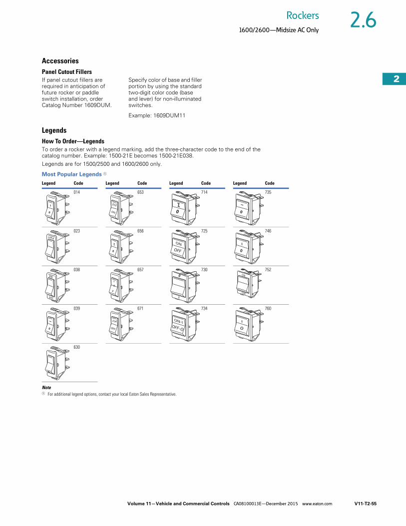
Volume 11—Vehicle and Commercial Controls CA08100013E—December 2015 www.eaton.com V11-T2-55
2
2
2
2
2
2
2
2
2
2
2
2
2
2
2
2
2
2
2
2
2
2
2
2
2
2
2
2
2
2
2.6Rockers
1600/2600—Midsize AC Only
AccessoriesPanel Cutout FillersIf panel cutout fillers are required in anticipation of future rocker or paddle switch installation, order Catalog Number 1609DUM.
Specify color of base and filler portion by using the standard two-digit color code (base and lever) for non-illuminated switches.
Example: 1609DUM11
LegendsHow To Order—LegendsTo order a rocker with a legend marking, add the three-character code to the end of the catalog number. Example: 1500-21E becomes 1500-21E038. Legends are for 1500/2500 and 1600/2600 only.
Most Popular Legends 1
Note1 For additional legend options, contact your local Eaton Sales Representative.
Legend Code Legend Code Legend Code Legend Code
014 653 714 735
023 656 725 746
038 657 730 752
039 671 734 760
630
I
0
OFF
ON
I
0 0
P OW ER
I
0
O F F
O N
I
0
OFF
ON
0

V11-T2-56 Volume 11—Vehicle and Commercial Controls CA08100013E—December 2015 www.eaton.com
2
2
2
2
2
2
2
2
2
2
2
2
2
2
2
2
2
2
2
2
2
2
2
2
2
2
2
2
2
2
2.7 Rockers
Rockette—General Purpose AC Rated
Rockette Series ContentsDescription Page
Rockette—General Purpose AC RatedStandard Rockette Switches . . . . . . . . . . . . . . . V11-T2-57
Sealed Rockette Switches. . . . . . . . . . . . . . . . . V11-T2-58
8058 Series Sealed Rockette Switches. . . . . . . V11-T2-59
Technical Data and Specifications . . . . . . . . . . V11-T2-60
Dimensions . . . . . . . . . . . . . . . . . . . . . . . . . . . V11-T2-60
Product DescriptionThese rocker switches offer the widest selection of features available, providing the design flexibility needed to fill the requirements of a variety of applications. They are available in two versions: standard and sealed.
The Sealed Rockette features a silicone rubber seal that protects contacts and mechanisms. All switches resist contaminants such as sand, dust and moisture with both a base-to-frame seal and an actuator seal. Non-illuminated and illuminated versions are available. For Sealed Rockette selection, see table on Page V11-T2-58.
Features and Benefits● Voltages
● 110 Vac neon● 14 Vdc and 28 Vdc
On the illuminated version, the lamp is wired to operate in conjunction with the switch on single-throw circuit; on double-throw circuits, the lamp is independent of the switch
● MountingFlush (two screws), sub-panel and snap-in mounting
● Snap-in MountingConvenient front panel or sub-panel snap-in mounting
Available in single- and two-pole non-illuminated or in single-pole illuminated Rockette switches. Contact your local Eaton Sales Representative for three- and four-pole circuits
Unless otherwise noted, all switches with snap-in mounting are UL Recognized and CSA Certified
Options
Standard and Sealed● Additional colors of rockers
and bezels are available● Hot stamped or pad
printed legends on rocker and bezel
● Paddle actuators● Single rocker operator on
two- and three-pole circuits● Dry circuits capabilities● Special ratings● Reversing jumpers● Dead back cover (two-pole
base) with wire leads● Special circuits● Printed circuit terminals
and other terminal types● Metal snap-in bezels● Foam dust seal
Sealed Only● Special voltage bulbs● Industry standard
connector available● Two-pole illuminated circuit
Standards and Certifications● UL Recognized● CSA Certified ● RoHS Compliant 1
Note1 Visit www.eaton.com/vcbu for
the most up-to-date list of verified part numbers.

Volume 11—Vehicle and Commercial Controls CA08100013E—December 2015 www.eaton.com V11-T2-57
2
2
2
2
2
2
2
2
2
2
2
2
2
2
2
2
2
2
2
2
2
2
2
2
2
2
2
2
2
2
2.7Rockers
Rockette—General Purpose AC Rated
Standard Rockette Switches To determine complete catalog number, start with the appropriate base circuit number and add the appropriate code letters and/or numbers.
Catalog Number SelectionHow To Order—Standard Rockette Switches
Notes1 These switches also have marked rating of 7A at 277 Vac and 3/4 hp at 277 Vac.2 Add code letters and numbers for mounting frame, rocker style and color and terminal construction.3 Also rated 2A, 277 Vac; 2.5A, L125 Vac.4 See Circuit Diagrams on Page V11-T2-80.5 See Frame Styles on Page V11-T2-61.6 See Rocker Styles on Page V11-T2-63.7 Cannot be used with snap-in mounting bezel.8 Recommended for use with snap-in mounting.
Rocker/Paddle Style 6
All Except 8130K20, 8140K20, 8140K21, 8140K22
6 = 2-pole7 = 2-pole
20 = 2-pole 7
37 = 2-pole 8
8130K20, 8140K20, 8140K21, 8140K2214 = 4-pole
8 1 3 2 K 2 1
Rating
Poles and Throw
Circuit with Rocker in …
Base Circuit Number 2
Circuit Number 4
UP Position
CENTER Position
DOWN Position
6A, 125 Vac3A, 250 Vac
2PST ON NONE OFF 8132K21 3 C
2PDT
ONONMOM. ONMOM. ON
OFFNONEOFFOFF
ONONMOM. ONON
8132K20 3
8132K22 3
8138K208138K30
D
15A, 125 Vac 10A, 250 Vac 3/4 hp, 250 Vac
2PST ONMOM. ON
NONENONE
OFFOFF
8142K218147K21 C
2PDT
ONONMOM. ONMOM. ON
OFFNONEOFFOFF
ONONMOM. ONON
8142K208142K228148K208148K30
D
1000W, 125 Vac10A, 250 Vac 2PST ON NONE OFF 8150K21 C
20A, 250 Vac2PST ON NONE OFF 8155K21 C
2PDT ONON
OFFNONE
ONON
8155K208155K22 D
6A, 125 Vac 3A, 250 Vac 4PDT ON OFF ON 8130K20 3 F
15A, 125 Vac 10A, 250 Vac 13/4 hp, 250 Vac
4PST ON NONE OFF 8140K21 E
4PDT ONON
OFFNONE
ONON
8140K208140K22 F
Example:
Mounting Frame 5
All Except 8130K20, 8140K20, 8140K21, 8140K22
E = Mounting, 2-poleF = Mounting, 2-poleG = Mounting, 2-pole
W = Snap-inX = Snap-inY = Snap-inZ = Snap-in
8130K20, 8140K20, 8140K21, 8140K22
H = Mounting, 4-pole
Code letters and/or numbers.Add to base circuit number.
Terminal Type50 = Screw51 = Solder lugs52 = 0.250 in spade
E 6 T 5 0
Rocker/Paddle ColorM = WhiteT = RedV = Black

V11-T2-58 Volume 11—Vehicle and Commercial Controls CA08100013E—December 2015 www.eaton.com
2
2
2
2
2
2
2
2
2
2
2
2
2
2
2
2
2
2
2
2
2
2
2
2
2
2
2
2
2
2
2.7 Rockers
Rockette—General Purpose AC Rated
Sealed Rockette Switches To determine complete catalog number, start with the appropriate base circuit number and add the appropriate code letters and/or numbers.
Catalog Number SelectionHow To Order—Sealed Rockette Switches, Non-Illuminated
How To Order—Sealed Rockette Switches, Illuminated
Notes1 See Circuit Diagrams on Page V11-T2-80.2 See Frame Styles on Page V11-T2-61.3 See Rocker Styles on Page V11-T2-63.
Rocker Style 3
1 = Two-face serrated2 = Three-face smooth7 = Concave
8 0 5 5 K 2 3
Rating
Poles and Throw
Circuit with Rocker in … Base Circuit Number
Circuit Number1
UP Position
CENTER Position
DOWN Position
Terminal Type
0.250 inSpade
SolderLugs Screw
15A, 125 Vac 10A, 250 Vac 3/4 hp, 250 Vac
1PST ON NONE OFF 8055K23 8055K24 8055K25 A
1PDT
ONONMOM. ONMOM. ON
OFFNONEOFFOFF
ONONONMOM. ON
8055K208055K268055K298055K32
8055K218055K278055K308055K33
8055K228055K288055K318055K34
B
15A, 125 Vac 10A, 250 Vac 3/4 hp, 250 Vac
2PST ON NONE OFF 8055K43 8055K44 8055K45 C
2PDT
ONONMOM. ONMOM. ON
OFFNONEOFFOFF
ONONONMOM. ON
8055K408055K468055K498055K52
8055K418055K478055K508055K53
8055K428055K488055K518055K54
D
Example:
Mounting Frame 2
E = StandardF = StandardL = StandardX = Snap-in
W = Snap-inZ = Snap-in
Code letters and/or numbers.Add to base circuit number.
E 2 V
Rocker Color
M = WhiteV = Black
Rocker Color
M = WhiteV = Black
Rocker Style 3
3 = Serrated w/1 lens5 = Smooth w/1 lens8 = Concave w/1 lens
8 0 5 7 K 2 3
Rating
Poles and Throw
Circuit with Rocker in … Base Circuit Number
Circuit Number1
UP Position
CENTER Position
DOWN Position
Terminal Type
0.250 inSpade
SolderLugs Screw
15A, 125 Vac 10A, 250 Vac
1PST ON NONE OFF 8057K23 8057K24 8057K25 G1PDT MOM. ON OFF ON 8057K29 8057K30 8057K31 H
Example:
Mounting Frame 2
E = StandardF = StandardL = StandardX = Snap-in
W = Snap-inZ = Snap-in
Code letters and/or numbers.Add to base circuit number.
Lens Color1 = Clear2 = Red4 = Amber5 = Blue
E 1 5 V 1
Bulb Voltage1 = Neon 110V3 = 14 Vdc filament4 = 28 Vdc filament

Volume 11—Vehicle and Commercial Controls CA08100013E—December 2015 www.eaton.com V11-T2-59
2
2
2
2
2
2
2
2
2
2
2
2
2
2
2
2
2
2
2
2
2
2
2
2
2
2
2
2
2
2
2.7Rockers
Rockette—General Purpose AC Rated
8058 Series Sealed Rockette SwitchesTo determine complete catalog number, start with the appropriate base circuit number and add the appropriate code letters and/or numbers.
Catalog Number SelectionHow To Order—Sealed Rockette Switches, Non-Illuminated
Notes1 Supplied with terminal screws, (Cat. No. 11-8616), unassembled. 2 See Circuit Diagrams on Page V11-T2-80.3 See Frame Styles on Page V11-T2-61.4 See Rocker Styles on Page V11-T2-63.
Rocker Style 4
1 = Two-face serrated2 = Three-face smooth7 = Concave
8 0 5 8 K 2 8
Rating
Poles and Throw
Circuit with Rocker in … Base Circuit Number
Circuit Number2
UP Position
CENTER Position
DOWN Position
Terminal Type
0.250 inSpade
SolderLugs
Screw 1
30A, 125 Vac 25A, 250 Vac 3/4 hp, 125 Vac2 hp, 250 Vac
1PST ON NONE OFF N/A N/A 8058K10 A
1PDT ON OFF ON N/A N/A 8058K22 B
1PDT ON NONE ON N/A N/A 8058K28 B
1PDT MOM ON OFF ON N/A N/A 8058K31 B
1PDT MOM ON OFF MOM ON N/A N/A 8058K34 B
Example:
Mounting Frame 3
E = Standard ears up with two tapped holes
F = Standard flat with two holesX = Metal snap-inZ = Standard plastic snap-in
W = Contour plastic snap-inL = Standard ears up with
two holes
Code letters and/or numbers.Add to base circuit number.
Z 7 V
Rocker ColorM = WhiteT = RedV = Black
8058K22E7V 8058K10X7T 8058K28Z7V
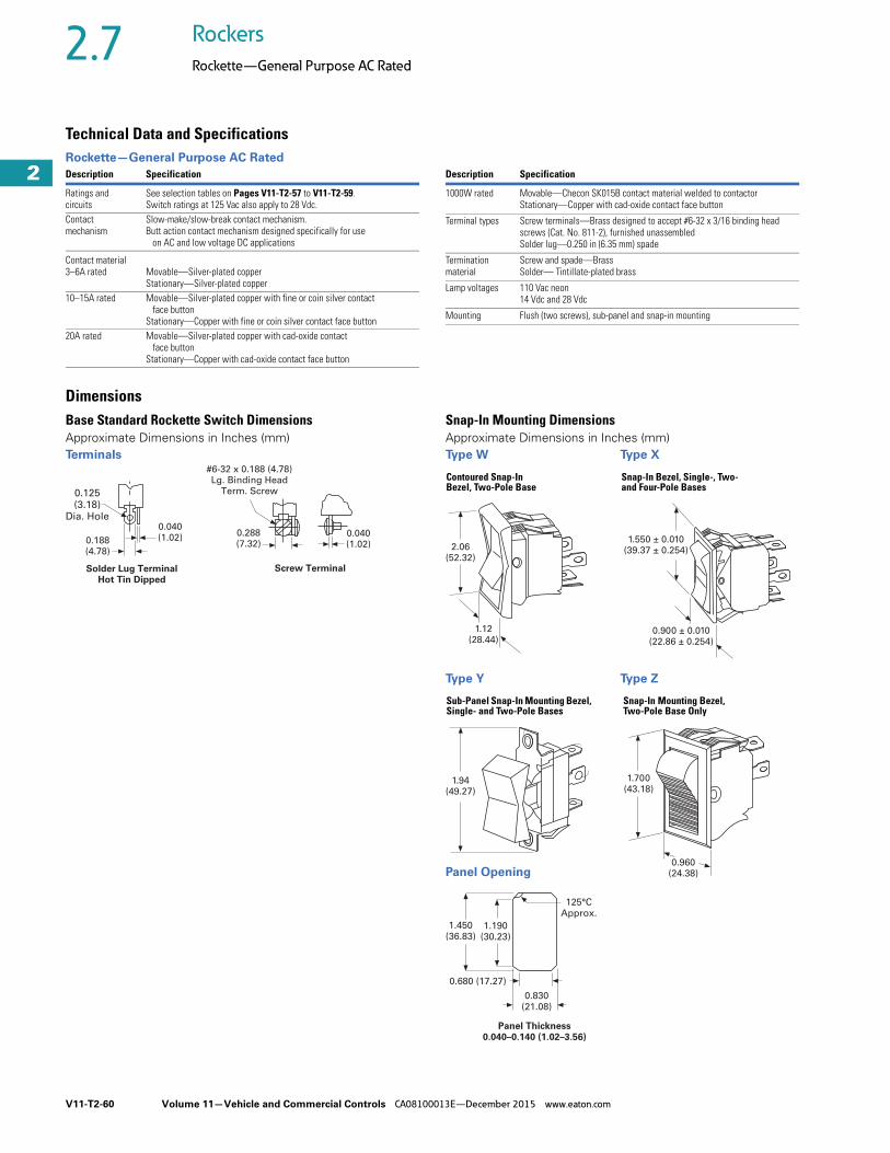
V11-T2-60 Volume 11—Vehicle and Commercial Controls CA08100013E—December 2015 www.eaton.com
2
2
2
2
2
2
2
2
2
2
2
2
2
2
2
2
2
2
2
2
2
2
2
2
2
2
2
2
2
2
2.7 Rockers
Rockette—General Purpose AC Rated
Technical Data and Specifications Rockette—General Purpose AC Rated
DimensionsBase Standard Rockette Switch DimensionsApproximate Dimensions in Inches (mm)Terminals
Snap-In Mounting DimensionsApproximate Dimensions in Inches (mm)Type W Type X
Type Y Type Z
Description Specification
Ratings and circuits
See selection tables on Pages V11-T2-57 to V11-T2-59.Switch ratings at 125 Vac also apply to 28 Vdc.
Contact mechanism
Slow-make/slow-break contact mechanism.Butt action contact mechanism designed specifically for use on AC and low voltage DC applications
Contact material3–6A rated Movable—Silver-plated copper
Stationary—Silver-plated copper10–15A rated Movable—Silver-plated copper with fine or coin silver contact
face buttonStationary—Copper with fine or coin silver contact face button
20A rated Movable—Silver-plated copper with cad-oxide contact face button
Stationary—Copper with cad-oxide contact face button
Description Specification
1000W rated Movable—Checon SK015B contact material welded to contactorStationary—Copper with cad-oxide contact face button
Terminal types Screw terminals—Brass designed to accept #6-32 x 3/16 binding head screws (Cat. No. 811-2), furnished unassembledSolder lug—0.250 in (6.35 mm) spade
Termination material
Screw and spade—BrassSolder— Tintillate-plated brass
Lamp voltages 110 Vac neon14 Vdc and 28 Vdc
Mounting Flush (two screws), sub-panel and snap-in mounting
0.125(3.18)
Dia. Hole
0.188
(4.78)
Solder Lug Terminal
Hot Tin Dipped
Screw Terminal
0.040
(1.02)
#6-32 x 0.188 (4.78)
Lg. Binding Head
Term. Screw
0.288
(7.32)0.040
(1.02) 2.06
(52.32)
1.12
(28.44)
1.550 ± 0.010
(39.37 ± 0.254)
0.900 ± 0.010
(22.86 ± 0.254)
Contoured Snap-In Bezel, Two-Pole Base
Snap-In Bezel, Single-, Two- and Four-Pole Bases
1.94
(49.27)
1.700
(43.18)
0.960
(24.38)
Sub-Panel Snap-In Mounting Bezel, Single- and Two-Pole Bases
Snap-In Mounting Bezel, Two-Pole Base Only
125°C
Approx.
0.680 (17.27)
1.450
(36.83)1.190
(30.23)
0.830
(21.08)
Panel Thickness
0.040–0.140 (1.02–3.56)
Panel Opening

Volume 11—Vehicle and Commercial Controls CA08100013E—December 2015 www.eaton.com V11-T2-61
2
2
2
2
2
2
2
2
2
2
2
2
2
2
2
2
2
2
2
2
2
2
2
2
2
2
2
2
2
2
2.7Rockers
Rockette—General Purpose AC Rated
Frame Types and Rocker/Paddle Styles for Standing Switches—Non-Illuminated DimensionsApproximate Dimensions in Inches (mm)
Two-Pole Mounting Frame Types
Two-Pole Rocker Styles
Four-Pole Mounting Frame Type Four-Pole Rocker Styles
Reference Dimension “CC”—Top of Frame to Bottom of Terminal
Rocker Style
Dimension in Inches (mm)
Rocker Style
Dimension in Inches (mm)Mounting Frame Type Mounting Frame TypeTwo-Pole Four-Pole
Type E Type F Type GRecommended Panel Opening Type H
Recommended Panel Opening
6 0.08 (2.03) 0.42 (10.67) 0.42 (10.67) 0.69 x 1.25 (17.53 x 31.75) 14 0.08 (2.03) 1.34 x 1.25 (34.04 x 31.75)
7 0.08 (2.03) 0.42 (10.67) 0.42 (10.67) 0.69 x 1.25 (17.53 x 31.75)
20 N/A 0.42 (10.67) 0.42 (10.67) N/A
37 N/A N/A N/A N/A
1.940 (49.28)
0.380
(9.65)
CC
1.620
(41.15)
#6-32 Tap 2 Holes
2.500 (63.50)
0.380
(9.65)
CC
2.250
(57.15)
0.150 (3.81) Dia. 2 Holes
2.120 (53.85)
0.380
(9.65)
CC
1.750
(44.45)
0.150 (3.81) Dia. 2 Holes
17.5° 0.200 (5.08)
0.100 (2.54)
0.380 ± 0.030
(9.65 ± 0.76)
0.850 ± 0.030
(21.59 ± 0.76)
0.640 ± 0.254
(16.26 ± 6.45)
Mounting Type
Recommended with This Style
Type E Type F Style 37 with Type X
Type G
0.650
(16.51)
R 0.610 (R 15.49)
CC
0.650
(16.51)
CC
R 0.610 (R 15.49)
0.880
(22.35)
0.660
(16.76)
17.5°
0.100
(2.54)
0.830
(21.08)
R 0.100
(R 2.54)
CC
Style 6 Style 7 Style 20
1.940 (49.28)
0.580
(14.73)
CC
1.620
(41.15)
#6-32
Tap 2 Holes
R 0.610
(R 15.49)
1.300
(33.02)CC
Type H Style 14

V11-T2-62 Volume 11—Vehicle and Commercial Controls CA08100013E—December 2015 www.eaton.com
2
2
2
2
2
2
2
2
2
2
2
2
2
2
2
2
2
2
2
2
2
2
2
2
2
2
2
2
2
2
2.7 Rockers
Rockette—General Purpose AC Rated
Base Sealed Rockette Switch DimensionsApproximate Dimensions in Inches (mm)
Sealed Two-Pole—Mounting Frame Type E—Rocker Style 1 Terminals
Sealed Two-Pole—Mounting Frame Type F—Rocker Style 1 Panel Opening
Snap-in Mounting Frame DimensionsApproximate Dimensions in Inches (mm)Sealed Two-Pole Switch—Mounting Frame Type W—Rocker Stye 7 Terminals
0.094 (2.39)
Max.
0.812
(20.62)
0.062
(1.57)
0.032
(0.81)
1.330
(33.83)
0.250 (6.35)
17.5˚
R 0.610 (R 15.49)
0.648 (16.46)
0.750
(19.05)
6-32 Tap
1.620 (41.15)
1.940 (49.28)
0.031 (0.79) Ref.
0.380 (9.65)
0.380 (9.65)
Quick
Connect
Term.
0.080
(2.03)
BB
AA
0.188
(4.78)0.040
(1.02)
#6-32 x 0.188 (4.78) Lg.
Binding Head
Term. Screws
Solder Lug Terminal
Hot Tin Dipped
Screw Terminal
0.288
(7.32)0.040
(1.02)
0.125 (3.18)
Dia. Hole
0.094
(2.39)
Max.
0.812
(20.62)
0.062
(1.57)
0.032
(0.81) Ref. 1.330 (33.83)
0.250
(6.35)
17.5˚
R 0.610
(R 15.49)0.648
(16.48)
0.750
(19.05)
2 Mtg. Holes
0.172 (4.37) Dia.
2.250 (57.15)
2.500 (63.50)
35˚
0.453
(11.51)
0.294
(7.47)
0.031/0.033
(0.79/0.84)
0.032
(0.81)
BB
AA
R 1.135
(R 28.83)
0.722
(18.34)1.450
(36.83)
1.190
(30.23)
125°C
Approx.
0.830
(21.80)
0.680
(17.27)
Panel Thickness
0.040–0.140 (1.02–3.56)
0.125 (3.18)
Dia. Hole
0.188
(4.78)
0.040
(1.02)
#6-32 x 0.188 (4.78) Lg.
Binding Head
Term. Screws
Solder Lug Terminal
Hot Tin Dipped
Screw Terminal
0.288
(7.32)
0.040
(1.02)
0.280
(7.11)
0.390
(9.91)
0.960
(24.38)
1.620 (41.15)
0.250
(6.35)
0.648
(16.46)
0.750
(19.05)
2.020 (51.31)
1.090
(27.69)
35˚0.126
(3.20)
0.031 (0.79) Ref.0.031
(0.79)
BB
AA
1.062 (26.97)
0.260 (6.60)
1.550 ± 0.010
(39.37 ± 0.254)
0.900 ± 0.010
(22.86 ± 0.254)
Snap-In Bezel
1.700
(43.18)
0.960
(24.38)
Snap-In Mounting Bezel
Type X Type Z Reference Dimensions “AA” and “BB” in Inches (mm) 1
Notes1 Dimension “AA”—Top of frame to bottom of terminal; “BB”—from bottom of base to bottom of terminal.2 #8-32 x 1/4 Phillips screw.
TerminalType
Dimension “AA” (Two-Pole) Dimension “BB”
E Frame F Frame L Frame W Frame X Frame Z Frame All Frames
Screw 1.39 (35.33) 1.05 (26.62) 1.39 (35.33) 1.37 (34.82) 1.39 (35.34) 1.37 (34.82) 0.30 (7.62)
Solder lug 1.36 (34.57) 1.02 (25.86) 1.36 (34.57) 1.34 (34.06) 1.36 (34.51) 1.34 (34.06) 0.27 (6.86)
0.250 in spade 1.53 (38.89) 1.19 (30.18) 1.53 (38.89) 1.51 (38.38) 1.53 (38.89) 1.51 (38.38) 0.44 (11.18)
8058 Screw 2 1.509 (38.33) 1.145 (29.08) 1.509 (38.33) 1.808 (45.92) 1.627 (41.33) 1.528 (38.81) 0.460 (11.68)
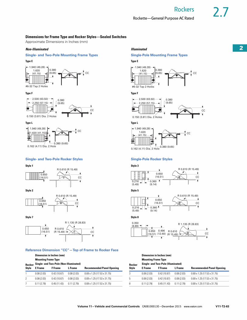
Volume 11—Vehicle and Commercial Controls CA08100013E—December 2015 www.eaton.com V11-T2-63
2
2
2
2
2
2
2
2
2
2
2
2
2
2
2
2
2
2
2
2
2
2
2
2
2
2
2
2
2
2
2.7Rockers
Rockette—General Purpose AC Rated
Dimensions for Frame Type and Rocker Styles—Sealed SwitchesApproximate Dimensions in Inches (mm)
Non-Illuminated
Single- and Two-Pole Mounting Frame Types
Single- and Two-Pole Rocker Styles
Illuminated
Single-Pole Mounting Frame Types
Single-Pole Rocker Styles
Reference Dimension “CC”—Top of Frame to Rocker Face
0.380
(9.65) CC1.620
(41.15)
#6-32 Tap 2 Holes
1.940 (49.28)
0.380
(9.65)
0.150 (3.81) Dia. 2 Holes
CC
2.500 (63.50)
2.250 (57.15)
0.162 (4.11) Dia. 2 Hole
1.940 (49.28)
0.380 (9.65)
1.620 (41.15)CC
Type E
Type F
Type L
0.650
(16.51) CC
R 0.610 (R 15.49)
0.650
(16.51) CC
R 0.610 (R 15.49)
R 1.135 (R 28.83)
R 0.610
(R 15.49) CC
0.650
(16.51)
Style 1
Style 2
Style 7
0.380
(9.65) CC1.620
(41.15)
#6-32 Tap 2 Holes
1.940 (49.28)
0.380
(9.65)
0.150 (3.81) Dia. 2 Holes
CC
2.500 (63.50)
2.250 (57.15)
0.162 (4.11) Dia. 2 Hole
1.940 (49.28)
0.380 (9.65)
1.620
(41.15)CC
Type E
Type F
Type L
0.650
(16.51)
0.360
(9.14)
0.216
(5.49)
CC
R 0.610 (R 15.49)
0.650
(16.51)
0.360
(9.14)
0.216
(5.49)
R 0.610 (R 15.49)
CC
0.650
(16.51)
0.496
(12.60)
0.350
(8.89)
CC
R 1.135 (R 28.83)
R 0.610
(R 15.49)
Style 3
Style 5
Style 8
Rocker Style
Dimension in Inches (mm)
Rocker Style
Dimension in Inches (mm)Mounting Frame Type Mounting Frame TypeSingle- and Two-Pole (Non-Illuminated) Single- and Two-Pole (Illuminated)E Frame F Frame L Frame Recommended Panel Opening E Frame F Frame L Frame Recommended Panel Opening
1 0.08 (2.03) 0.42 (10.67) 0.08 (2.03) 0.69 x 1.25 (17.53 x 31.75) 3 0.08 (2.03) 0.42 (10.67) 0.08 (2.03) 0.69 x 1.25 (17.53 x 31.75)
2 0.08 (2.03) 0.42 (10.67) 0.08 (2.03) 0.69 x 1.25 (17.53 x 31.75) 5 0.08 (2.03) 0.42 (10.67) 0.08 (2.03) 0.69 x 1.25 (17.53 x 31.75)
7 0.11 (2.79) 0.45 (11.43) 0.11 (2.79) 0.69 x 1.25 (17.53 x 31.75) 8 0.11 (2.79) 0.45 (11.43) 0.11 (2.79) 0.69 x 1.25 (17.53 x 31.75)

V11-T2-64 Volume 11—Vehicle and Commercial Controls CA08100013E—December 2015 www.eaton.com
2
2
2
2
2
2
2
2
2
2
2
2
2
2
2
2
2
2
2
2
2
2
2
2
2
2
2
2
2
2
2.8 Rockers
8006/8007—EURO SR
8006/8007 Series ContentsDescription Page
8006/8007—EURO SRCatalog Number Selection . . . . . . . . . . . . . . . . V11-T2-65
Technical Data and Specifications . . . . . . . . . . V11-T2-66
Dimensions . . . . . . . . . . . . . . . . . . . . . . . . . . . V11-T2-66
Product DescriptionField-proven in America’s roughest off-road applications, the standard size EURO SR is one tough and reliable rocker switch. Available with the complete range of rugged single- and two-pole, illuminated or non-illuminated circuits.
The EURO SR Series offers snap-in mounting and can be provided with a durable silicone seal that resists dust and moisture.
All EURO SR switches are molded in an aesthetically pleasing matte finish and operate with a crisp tactile feel, allowing for easy actuation.
The EURO SR will accept loads up to 15A. Terminal numbers are stamped on base for easy identification.
Features and Benefits● Contact MechanismSlow-make/slow-break contact mechanism. Butt action contact mechanism designed specifically for use on AC and low voltage DC applications.
● Rocker MaterialThermoplastic rocker actuators. Different colors are available. Rocker and bezel are a high-grade nylon supplied with matte finish.
● LampsFive lamp voltages—14 Vdc, 18 Vdc, 28 Vdc, 125 Vac neon and 250 Vac neon—are offered as standard. For additional lamp voltages, please contact your local Eaton Sales Representative.
● Mounting MeansSnap-in mounting with plastic bezel.
● SealAvailable in sealed and non-sealed versions. Sealed devices are furnished with silicone rubber seal, providing moisture and dust resistance with an IP67 rating.
Options● Additional colors of rockers
and bezels are available● Special circuits● Special ratings● Pad-printed legends on
rocker and bezel● Special voltage bulbs● Dry circuit capabilities● Foam dust seal● Reversing jumpers● Printed circuit terminals
and other terminal types● Wire leads● Dead back cover● Palm guard● Industry standard
connector: 28-3426● EURO SR panel plug:
53-3318For information on optional features, contact your local Eaton Sales Representative.
Lens Options● Lens Part Numbers
(if ordered separately)Green . . . . . . . . . . 28-5415Amber . . . . . . . .28-5415-2Red. . . . . . . . . . .28-5415-3Blue . . . . . . . . . .28-5415-4White . . . . . . . . .28-5415-5
Standards and Certifications● UL Recognized and
recognized component for Canada File E2702
● RoHS Compliant 1
Note1 Visit www.eaton.com/vcbu for
the most up-to-date list of verified part numbers.

Volume 11—Vehicle and Commercial Controls CA08100013E—December 2015 www.eaton.com V11-T2-65
2
2
2
2
2
2
2
2
2
2
2
2
2
2
2
2
2
2
2
2
2
2
2
2
2
2
2
2
2
2
2.8Rockers
8006/8007—EURO SR
EURO SR Standard Size Euro-Style Rocker SwitchesTo determine complete catalog number, start with the appropriate base circuit number and add the appropriate code letters and/or numbers.
Catalog Number SelectionHow To Order—EURO SR, Non-Illuminated
How To Order—EURO SR, Illuminated
Notes1 Momentary contact.2 3A at 250 Vac, 6A at 125 Vac.3 1/4 hp at 125–250 Vac.4 All double-throw circuits, both 1PDT and 2PDT, provided with two lamps and two lenses (Rocker Style 4). When lamp is wired independent of circuit for 1PDT switches, device is supplied with lamp
centered in open-pole of base.5 Not standard with lamp wired independent of circuit. All 2PDT switches must be dependent on circuit and use Rocker Style 4.6 Not provided standard for double-throw circuits, both 1PDT and 2PDT. Must use Rocker Style 4 for all double-throw switches.7 Available on single-pole versions only.8 14 Vdc, 18 Vdc and 28 Vdc bulbs are not UL, CSA when bulb is wired dependent to switch circuit.
Rocker Style
1 = Two-face
8 0 0 6 K 2 3
Rating
Poles and Throw
Circuit with Rocker in … Terminal TypeUP Position
CENTER Position
DOWN Position
0.250 in Spade
Solder Lugs Screw
10A, 250 Vac15A, 125 Vac15A, 28 Vdc
1PST 2-32-3 1
NONE OFF 8006K238006K35
8006K248006K36
8006K258006K37
1PDT
2-32-32-3 12-3 1
OFFNONEOFFOFF
2-12-12-12-1 1
8006K208006K268006K298006K32
8006K218006K278006K308006K33
8006K228006K288006K318006K34
2PST 2-3, 5-62-3, 5-6 1
NONE OFF 8006K438006K55
8006K448006K56
8006K458006K57
2PDT
2-3, 5-62-3, 5-62-3, 5-6 12-3, 5-6 1
OFFNONEOFFOFF
2-1, 5-42-1, 5-42-1, 5-42-1, 5-4 1
8006K408006K468006K498006K52
8006K418006K478006K508006K53
8006K428006K488006K518006K54
2PDT 2 2-3, 5-6 5-6 OFF 8006K58 8006K59 8006K602PDT 3 5-6 5-3 5-1 8006K61 8006K62 8006K63
Example:
Mounting FrameColor /Style
N = Black/standardT = Black/top half
palm guardB = Black/bottom half
palm guard
Code letters and/or numbers.Add to base circuit number.
Seal Option
1 = Non-sealed2 = Sealed
N 1 T 1
Rocker ColorM = WhiteT = RedV = Black
Rocker Style 3 = Two-face
w/1 lens 6
4 = Two-facew/2 lenses 4
8 0 0 7 K 2 3
Rating
Poles and Throw
Circuit with Rocker in … Terminal TypeUP Position
CENTER Position
DOWN Position
0.250 in Spade
Solder Lugs Screw
10A, 250 Vac15A, 125 Vac15A, 28 Vdc
1PST OFFNONE
NONEOFF
2-12-11
8007K238007K35
8007K248007K36
8007K258007K37
1PDT 4
2-32-32-3 12-3 1
OFFNONEOFFOFF
2-12-12-12-1 1
8007K208007K268007K298007K32
8007K218007K278007K308007K33
8007K228007K288007K318007K34
2PST OFF2-3, 5-6 1
NONEOFF
2-1, 5-4NONE
8007K438007K55
8007K448007K56
8007K458007K57
2PDT 45
2-3, 5-62-1, 5-42-3, 5-6 12-3, 5-6 1
OFFNONEOFFOFF
2-1, 5-42-3, 5-62-1, 5-42-1, 5-4 1
8007K408007K468007K498007K52
8007K418007K478007K508007K53
8007K428007K488007K518007K54
Example:
Code letters and/or numbers.Add to base circuit number.
Seal Option
1 = Non-sealed2 = Sealed
N 4 1 3 T 2 1
Rocker ColorM = WhiteT = RedV = Black
Bulb Voltage1 = 125V neon 7
2 = 250V neon 7
3 = 14 Vdc 8
4 = 28 Vdc 8
7 = 18 Vdc 8
Lamp Wiring 1 = Dependent 2 = Independent
Lens Color1 = White2 = Red3 = Green4 = Amber5 = No lens6 = Blue7 = Clear
Mounting FrameColor /Style
N = Black/standardT = Black/top half
palm guardB = Black/bottom
half palm guard

V11-T2-66 Volume 11—Vehicle and Commercial Controls CA08100013E—December 2015 www.eaton.com
2
2
2
2
2
2
2
2
2
2
2
2
2
2
2
2
2
2
2
2
2
2
2
2
2
2
2
2
2
2
2.8 Rockers
8006/8007—EURO SR
Technical Data and Specifications 8006/8007—EURO SR
DimensionsApproximate Dimensions in Inches (mm)
Non-Illuminated Illuminated
Palm Guard
Description Specification
Ratings 15A at 125 Vac10A at 250 Vac3/4 hp at 250 Vac(hp rating does not apply to lighted switches) Switch ratings at 125 Vac also apply to 28 Vdc
Circuits 1PST, 1PDT, 2PST and 2PDTMaintained and momentary action
Mechanical life Maintained—100,000 operations, minimumMomentary—25,000 operations, minimum
Electrical life 25,000 operations minimum at full loadTerminal types Standard 0.250 in (6.35 mm)
Spade—BrassScrew—Brass (terminal screws provided unassembled) Solder—Tintillate-plated brass
Base material Thermoset molding materialRocker material Thermoplastic rocker actuators Dielectric 1000V rms, minimum Seal level IP67 (with optional seal)Mounting means Snap-in mounting with plastic bezel Operating temperature –40° to 185°F (–40° to 85°C)
Panel Opening
Reference Only
Thickness:
0.040 to 0.140 (1.02 to 3.56)
Best Results Obtained from:
0.080 to 0.125 (2.03 to 3.18)
0.680 (17.27)
0.830
(21.08)
1.450
(36.85)
1.190
(30.23)
R 0.156 ± 0.010
(R 3.96 ± 0.25)
1.705 ± 0.011
(43.31 ± 0.31)
0.957 ± 0.012
(24.31 ± 0.30)
0.250 ± 0.004
(6.35 ± 0.08)
0.030 (0.813) Thick 0.440 ± 0.005
(11.18 ± 0.13)
0.389 ± 0.041
(9.88 ± 1.06)
0.096 ± 0.010
(2.44 ± 0.25)
1.082 ± 0.012
(27.48 ± 0.30)
1.427 + 0.020/– 0.012
(36.25 + 0.51/– 0.38)
0.820 ± 0.005
(20.83 ± 0.13)
1 2 3
4 5 6
R 0.156 ± 0.010
(R 3.96 ± 0.25)
1.705 ± 0.011
(43.31 ± 0.31)
0.957 ± 0.012
(24.31 ± 0.30)
1.705 ±0.012(43.31 ±0.30)
R 0.156 ±0.005(3.97 ±0.13)
1.220 ±0.012(30.99 ±0.30)
0.389 ±0.040
(9.88 ±1.02)
0.096 ±0.010(2.44 ±0.25)

Volume 11—Vehicle and Commercial Controls CA08100013E—December 2015 www.eaton.com V11-T2-67
2
2
2
2
2
2
2
2
2
2
2
2
2
2
2
2
2
2
2
2
2
2
2
2
2
2
2
2
2
2
2.9Rockers
8004/8005—Euro Full Size
8004/8005–Euro Full Size ContentsDescription Page
8004/8005—Euro Full SizeCatalog Number Selection . . . . . . . . . . . . . . . . V11-T2-68
Technical Data and Specifications . . . . . . . . . . V11-T2-69
Dimensions . . . . . . . . . . . . . . . . . . . . . . . . . . . V11-T2-69
Product DescriptionEaton’s 8004 and 8005 Euro-Look Series features matte finish European styling and snap-in mounting. These durable switches, field-tested in the most demanding truck and marine applications, are available with a variety of standard actuator options. Options include concave, two-face, illuminated, non-illuminated and the recessed feature, which allows placement of your label on the face of our rocker. All switches in this rugged lineup can be fitted with a silicone rubber seal to provide moisture and dust-resistance. Additionally, these switches can be gang-mounted into a single panel opening. Panel blanks are also available.
Features and Benefits● Contact MechanismSlow-make/slow-break contact mechanism. Butt action contact mechanism designed specifically for use on AC and low voltage DC applications.
● Rocker MaterialCustom styled, multi-colored thermoplastic rocker actuators. The rocker and bezel are supplied with a matte finish.
● LampsFive lamp voltages—14 Vdc, 18 Vdc, 28 Vdc, 125 Vac neon and 250 Vac neon—are offered as standard. For additional lamp voltages, please contact your local Eaton Sales Representative.
● Mounting MeansSnap-in mounting with plastic bezel.
● SealAvailable in sealed and non-sealed versions. Sealed devices are furnished with a silicone rubber seal providing moisture and dust resistance with an IP54 rating.
Options● Additional colors of rockers
and mounting bezels are available
● Special circuits● Special ratings● Gold contacts● Dry circuit capabilities● Pad-printed legends on
rocker and bezel● Special lamp voltages● Foam dust seal● Reversing jumpers● Printed circuit terminals
and other terminal types● Dead back cover (two-pole
base) with wire leads● Matching indicators● Industry standard
connector: 28-3426● Full size Euro-Look gang
mounting systems● Full size Euro-Look panel
plugs: 17-19544-2For information on optional features, contact your local Eaton Sales Representative.
Lens Options● Lens Part Numbers
(if ordered separately)8005 Two-FaceGreen . . . . . . . . . 28-3425Amber . . . . . . . . 28-3425-2Red . . . . . . . . . . 28-3425-3Blue. . . . . . . . . . 28-3425-4White . . . . . . . . 28-3425-5
8005 ConcaveRed . . . . . . . . . . . 28-5148Green . . . . . . . . 28-5148-2Amber . . . . . . . . 28-5148-3Blue. . . . . . . . . . 28-5148-4Clear . . . . . . . . . 28-5148-5
Standards and Certifications● UL Recognized and
recognized component for Canada File E2702
● RoHS Compliant 1
Note1 Visit www.eaton.com/vcbu for
the most up-to-date list of verified part numbers.

V11-T2-68 Volume 11—Vehicle and Commercial Controls CA08100013E—December 2015 www.eaton.com
2
2
2
2
2
2
2
2
2
2
2
2
2
2
2
2
2
2
2
2
2
2
2
2
2
2
2
2
2
2
2.9 Rockers
8004/8005—Euro Full Size
Full Size, Euro-Look Rocker SwitchesTo determine complete catalog number, start with the appropriate base circuit number and add the appropriate code letters and/or numbers.
Catalog Number SelectionHow To Order—Full Size Euro, Non-Illuminated
How To Order—Full Size Euro, Illuminated
Notes1 Momentary contact.2 3A at 250 Vac, 5A at 125 Vac.3 1/4 hp at 125–250 Vac.4 All double-throw circuits, both 1PDT and 2PDT, provided with two lamps and two lenses (Rocker Style 4). When lamp is wired independent of circuit for 1PDT switches, device is supplied with lamp
centered in open-pole of base.5 Not standard available with lamp wired independent of circuit. All 2PDT switches must be dependent on circuit and use Rocker Style 4, 5 or 9.6 Not provided standard for double-throw circuits, both 1PDT and 2PDT. Must use Rocker Style 4, 5 or 9 for all double-throw switches.7 Available on single-pole versions only.8 14 Vdc and 28 Vdc bulbs are not UL, CSA when bulb is wired dependent to switch circuit.
Rocker Style 0 = Recessed1 = Two-face6 = Paddle7 = Concave
8 0 0 4 K 2 3
Rating
Poles and Throw
Circuit with Rocker in … Terminal TypeUP Position
CENTER Position
DOWN Position
0.250 in Spade
Solder Lugs Screw
10A, 250 Vac15A, 125 Vac15A, 28 Vdc
1PST 2-32-3 1 NONE OFF 8004K23
8004K358004K248004K36
8004K258004K37
1PDT
2-32-32-3 12-3 1
OFFNONEOFFOFF
2-12-12-12-1 1
8004K208004K268004K298004K32
8004K218004K278004K308004K33
8004K228004K288004K318004K34
2PST 2-3, 5-62-3, 5-6 1 NONE OFF 8004K43
8004K558004K448004K56
8004K458004K57
2PDT
2-3, 5-62-3, 5-62-3, 5-6 12-3, 5-6 1
OFFNONEOFFOFF
2-1, 5-42-1, 5-42-1, 5-42-1, 5-4 1
8004K408004K468004K498004K52
8004K418004K478004K508004K53
8004K428004K488004K518004K54
2PDT 2 2-3, 5-6 5-6 OFF 8004K58 8004K59 8004K602PDT 3 5-6 5-3 5-1 8004K61 8004K62 8004K63
Example:
Mounting Frame Color
N = BlackM = WhiteT = RedG = Gray
Code letters and/or numbers.Add to base circuit number.
Seal Option
1 = Non-sealed2 = Sealed
N 1 T 1
Rocker ColorM = WhiteT = RedV = BlackG = Gray
Rocker Style 2 = Recessed
w/1 lens 6
3 = Two-face w/1 lens 6
4 = Two-facew/2 lenses 4
5 = Recessedw/2 lenses 4
8 = Concavew/1 lens 6
9 = Concavew/2 lenses 4
8 0 0 5 K 2 3
Rating
Poles and Throw
Circuit with Rocker in … Terminal TypeUP Position
CENTER Position
DOWN Position
0.250 in Spade
Solder Lugs Screw
10A, 250 Vac15A, 125 Vac15A, 28 Vdc
1PST OFFNONE
NONEOFF
2-12-1 1
8005K238005K35
8005K248005K36
8005K258005K37
1PDT 4
2-32-32-3 12-3 1
OFFNONEOFFOFF
2-12-12-12-1 1
8005K208005K268005K298005K32
8005K218005K278005K308005K33
8005K228005K288005K318005K34
2PST OFF2-3, 5-6 1
NONEOFF
2-1, 5-4NONE
8005K438005K55
8005K448005K56
8005K458005K57
2PDT 45
2-3, 5-62-1, 5-42-3, 5-6 12-3, 5-6 1
OFFNONEOFFOFF
2-1, 5-42-3, 5-62-1, 5-42-1, 5-4 1
8005K408005K468005K498005K52
8005K418005K478005K508005K53
8005K428005K488005K518005K54
Example:
Mounting Frame Color
N = BlackM = WhiteT = RedG = Gray
Code letters and/or numbers.Add to base circuit number.
Seal Option
1 = Non-sealed2 = Sealed
N 4 1 3 T 2 1
Rocker ColorM = WhiteT = RedV = BlackG = Gray
Bulb Voltage1 = 125V neon 7
2 = 250V neon 7
3 = 14 Vdc 8
4 = 28 Vdc 8
7 = 18 Vdc 8
Lamp Wiring 1 = Dependent 2 = Independent
Lens Color2 = Red3 = Green4 = Amber5 = No lens6 = Blue

Volume 11—Vehicle and Commercial Controls CA08100013E—December 2015 www.eaton.com V11-T2-69
2
2
2
2
2
2
2
2
2
2
2
2
2
2
2
2
2
2
2
2
2
2
2
2
2
2
2
2
2
2
2.9Rockers
8004/8005—Euro Full Size
Technical Data and Specifications 8004/8005—Euro Full Size
DimensionsApproximate Dimensions in Inches (mm)
Non-Illuminated Illuminated
Description Specification
Ratings 15A at 125 Vac; 10A at 250 Vac; 3/4 hp at 250 Vac(hp rating does not apply to lighted switches) Switch ratings at 125 Vac also apply to 28 Vdc
Circuits 1PST, 1PDT, 2PST and 2PDT; Maintained and momentary actionContact material Movable—Silver-plated copper with fine or coin silver contact face button
Stationary—Copper with fine or coin silver contact face buttonMechanical life Maintained—100,000 operations, minimum
Momentary—25,000 operations, minimumElectrical life 25,000 operations minimum at full loadTerminal types Standard 0.250 in (6.35 mm) spade—Brass
Screw—Brass #6-32 x 3/16 (terminal screws provided unassembled) Solder—Tintillate-plated brass; tintillate spade terminals
Base material Thermoset molding materialDielectric 1000V rms, minimum Seal level IP54 (with optional seal)Mounting means Snap-in mounting with plastic bezel
1.734 ± 0.005
(44.04 ± 0.13)
0.867 ± 0.005
(22.02 ± 0.13)
R 0.004 ± 0.005
(R 0.125 ± 0.13)
0.519 ± 0.005
(13.18 ± 0.13)
1.087 ± 0.005
(27.61 ± 0.13)
Surface Length Along
Bottom of Recess:
1.122 ± 0.012 (28.50 ± 0.31)
1.970 ± 0.010
(50.04 ± 0.25)
1.440 ± 0.010
(36.58 ± 0.25)
0.689 ± 0.010
(17.50 ± 0.25)
0.395 ± 0.029
(10.03 ± 0.76)
0.440 ± 0.010
(11.18 ± 0.25)1.602 ± 0.029
(40.69 ± 0.76)
0.687 ± 0.015
(17.45 ± 0.38)
0.328 ± 0.015
(8.33 ± 0.38)
R 0.156 (R 3.96) Typ.
1 2 3
4 5 6
0.090 ± 0.005
(2.29 ± 0.13)
0.080 (2.03)
0.031 (0.79)
R 0.060 (R 1.52)
0.250 ± 0.032 (6.35 ± 0.81)
0.001 (0.032) Thick
Panel Opening
Reference Only
Thickness:
0.030 to 0.190 (0.76 to 4.83)
Best Results Obtained From:
0.080 to 0.130 (2.03 to 3.30)
1.024 ± 0.010
(26.01 ± 0.25)

V11-T2-70 Volume 11—Vehicle and Commercial Controls CA08100013E—December 2015 www.eaton.com
2
2
2
2
2
2
2
2
2
2
2
2
2
2
2
2
2
2
2
2
2
2
2
2
2
2
2
2
2
2
2.10 Rockers
X Series Rockers
X Series Rockers—XR ContentsDescription Page
X Series RockersCatalog Number Selection . . . . . . . . . . . . . . . . V11-T2-71
X Series Symbols Library . . . . . . . . . . . . . . . . . V11-T2-72
Technical Data and Specifications . . . . . . . . . . V11-T2-72
Light Diagrams . . . . . . . . . . . . . . . . . . . . . . . . . V11-T2-72
Dimensions . . . . . . . . . . . . . . . . . . . . . . . . . . . V11-T2-73
Product DescriptionThe Electrical Sector is pleased to offer X Series Rockers for use in outdoor applications to meet almost every market need.
These sleek style rockers are molded in a unique smooth matte finish. The bezel is also unique with a more modern rounded-rectangular design with an oval shaped rocker. X Series Rockers are available in single- and double-pole with various circuit options, LED illumination, and laser etching.● Frames and actuator colors
are black● Switches provided with
0.025 spade quick connect terminals
Application DescriptionMarket Applications● Agriculture● Bus ● Commercial● Marine● Specialty Vehicle● Truck
Features and Benefits● SealStandard IP56 Sealing per IES 60529.
● IlluminationStandard LED voltages offered include 14 Vdc and 125 Vac.
● MaterialFrames are nylon and actuators are nylon with glass fiber with both meeting UL flame: 94HB. Terminals are silver plated brass.
● Mounting MeansEasy snap-in mounting with plastic bezel.
● LabelEaton part number etched on switch for easy inventory management.
Options● Panel plug: 53-3318● Industry standard
connector: 28-3426● For information on optional
features, contact your local Eaton Sales Representative.
Standards and Certifications● UL Recognized and
recognized component for Canada File E2702
● T85● RoHS Compliant
Product Selection Guide
Seal
Top ✔
Bottom —
Panel —
Actuator
Rocker without bezel —
Rocker with bezel ✔
Paddle —
Snap-in lens —
Locking —
Label —
Decorative
Laser-etch ✔
Pad-print —
Poles
Single ✔
Double ✔
Four —
Termination
Spade ✔
Solder —
Screw —
Weld lugs —
Illumination
Incandescent 6 Vdc — Neon 110V —
Incandescent 12 Vdc — Neon 125V —
Incandescent 14 Vdc — Neon 250V —
Incandescent 18 Vdc — 14 Vdc LED ✔
Incandescent 24 Vdc — 28 Vdc LED —
Incandescent 28 Vdc — 125 Vac LED ✔
277 Vac LED —

Volume 11—Vehicle and Commercial Controls CA08100013E—December 2015 www.eaton.com V11-T2-71
2
2
2
2
2
2
2
2
2
2
2
2
2
2
2
2
2
2
2
2
2
2
2
2
2
2
2
2
2
2
2.10Rockers
X Series Rockers
X Series Rockers
Catalog Number SelectionStandard rating 16A 125V, 10A 277V, 3/4 hp 277VAlso recommended for use in applications up to 21A 14 VdcIP56 per IES 60529
Product Selection
X Series Rockers
Notes1 Available in AC applications only.2 Double-pole not available illuminated; it is available laser etched.3 See Circuit Diagrams on Page V11-T2-72.4 See Symbols Library on Page V11-T2-72.
Lamp Voltage
Switch Function
Light Circuit 3
Lens Color T. 1-4 T. 3-6
Switch Markings Catalog Number
None SPST OFF-ON X = None None None Int’l ON/OFF 4 XRXAXXXNV1CU
SPST OFF-ON X = None None None ON/OFF 4 XRXAXXXNV1DB
14 Vdc LED SPST OFF-ON E = None Amber None XR1AEX4NV1XX
SPST OFF-ON E = None Green None XR1AEX3NV1XX
SPST OFF-ON E = None Red None XR1AEX2NV1XX
SPDT ON-ON G = Amber Amber None XR1CG44NV1XX
SPDT ON-ON G = Green Green None XR1CG33NV1XX
SPDT ON-OFF-ON G = Amber Amber None XR1BG44NV1XX
SPDT ON-OFF-ON G = Green Green None XR1BG33NV1XX
SPDT (ON)-OFF-(ON) G = Amber Amber None XR1EG44NV1XX
SPDT (ON)-OFF-(ON) G = Green Green None XR1EG33NV1XX
None DPST OFF-ON 2 X = None None None Int’l ON/OFF 4 XRXMXXXNV1CU
DPST OFF-ON 2 X = None None None ON/OFF 4 XRXMXXXNV1DB
DPST OFF-ON X = None None None None XRXMXXXNV1XX
DPST ON-ON X = None None None None XRXNXXXNV1XX
125 Vac LED 1 SPST OFF-ON E = None Amber None XR3AEX4NV1XX
SPST OFF-ON E = None Green None XR3AEX3NV1XX
SPST OFF-ON E = None Red None XR3AEX2NV1XX
SPDT ON-ON G = Amber Amber None XR3CG44NV1XX
SPDT ON-ON G = Green Green None XR3CG33NV1XX
SPDT ON-OFF-ON G = Amber Amber None XR3BG44NV1XX
SPDT ON-OFF-ON G = Green Green None XR3BG33NV1XX
SPDT (ON)-OFF-(ON) G = Amber Amber None XR3EG44NV1XX
SPDT (ON)-OFF-(ON) G = Green Green None XR3EG33NV1XX
XR Series Rocker
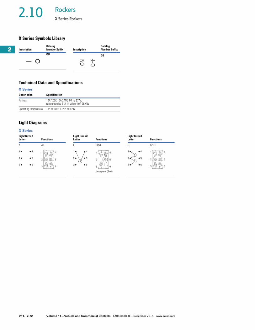
V11-T2-72 Volume 11—Vehicle and Commercial Controls CA08100013E—December 2015 www.eaton.com
2
2
2
2
2
2
2
2
2
2
2
2
2
2
2
2
2
2
2
2
2
2
2
2
2
2
2
2
2
2
2.10 Rockers
X Series Rockers
X Series Symbols Library
Technical Data and Specifications X Series
Light Diagrams
X Series
InscriptionCatalog Number Suffix
CU
InscriptionCatalog Number Suffix
DB
Description Specification
Ratings 16A 125V, 10A 277V, 3/4 hp 277V; recommended 21A 14 Vdc or 10A 28 Vdc
Operating temperature –4° to 176°F (–20° to 80°C)
Light Circuit Letter Functions
Light Circuit Letter Functions
Light Circuit Letter Functions
X All E SPST G SPDT
1
2
3
4
5
6
1
2
3
4
5
6
1
2
2
3
4
5
6
1
2
3
4
5
Jumpers (3–4)
6
1
1
2
2
3
4
5
6
1
2
3
4
5
6

Volume 11—Vehicle and Commercial Controls CA08100013E—December 2015 www.eaton.com V11-T2-73
2
2
2
2
2
2
2
2
2
2
2
2
2
2
2
2
2
2
2
2
2
2
2
2
2
2
2
2
2
2
2.10Rockers
X Series Rockers
DimensionsApproximate Dimensions in Inches (mm)
Mounting Hole
X Series
Dimensions
Thickness0.03–0.12 (0.75–3.0)
X0.83 +0.01 (21.2 +0.1)
Y1.46 + 0.01 (37.0 +0.1)
X
Y
LED 1 LED 2
1.81 (46.0)
0.98(25.0)
ON ONOFF
0.32(8.0)
1.11(28.2)
0.09(2.2)
0.25(6.4)
1.43 (36.2)
0.81(20.7)0.44
(11.2)
0.03(0.8)
0.81(20.7)

V11-T2-74 Volume 11—Vehicle and Commercial Controls CA08100013E—December 2015 www.eaton.com
2
2
2
2
2
2
2
2
2
2
2
2
2
2
2
2
2
2
2
2
2
2
2
2
2
2
2
2
2
2
2.11 Rockers
8064/8065—ESPORT
8064/8065 Series ContentsDescription Page
8064/8065—ESPORT Catalog Number Selection . . . . . . . . . . . . . . . . V11-T2-75
Technical Data and Specifications . . . . . . . . . . V11-T2-76
Icon/Legend Selection . . . . . . . . . . . . . . . . . . . V11-T2-76
Dimensions . . . . . . . . . . . . . . . . . . . . . . . . . . . V11-T2-77
Product DescriptionThe ergonomically designed ESPORT Series comes with a large, independent LED-illuminated indicator window that clearly identifies the switch’s labeled function—your label or ours. The switch can be ordered with an LED illuminated actuator, as well. All ESPORT switches are molded in a clean matte finish and operate with a definite tactile feel. Actuation of the switch feels crisp. Also, ESPORT switches will accept loads up to15A. Due to the LED’s long life, lamp replacement should not be necessary.
Tested in America’s toughest truck applications, the ESPORT switch is reliable and durable and is available with a full range of rugged single- and two-pole circuits. It has an optional polarized lock-on connector. Spade switch terminals are tin-plated for long storage life.
Features and Benefits● Contact MechanismSlow-make/slow-break contact mechanism. Butt action contact mechanism designed specifically for use on AC and low voltage DC applications.
● Rocker MaterialThermoplastic rocker actuators. Different colors are available. The rocker and the bezel are a high-grade nylon and are supplied with an aesthetically pleasing matte finish.
● LampsDurable, long-life LED illumination; 14 Vdc is standard. Integral indicator is illuminated by two independent green, yellow or red LEDs while the actuator is lighted using one dependent LED. For additional LED voltages and/or colors, contact your local Eaton Sales Representative.
● Mounting MeansSnap-in mounting with plastic bezel.
● LensesAll switches can be ordered with either a frosted clear lens (Cat. No. 28-5555) or a translucent white lens (Cat. No. 28-5555-2). The clear lens will allow the maximum amount of diffused light to flow through your label or one of ours. The white lens is shipped unassembled to facilitate the addition of your engraved or pad-printed legend.
● LabelsThe lens area of the integral indicator will accept a label 0.750 x 0.450 and 0.010 in (19.05 x 11.43 x 0.25 mm) thick. Our selection of standard labels with white legends on black poly-carbonate background can be found on Page V11-T2-76.
Options● Additional colors of rockers
and mounting bezels are available
● Special circuits● Special ratings● Dry circuit capabilities● Pad-printed legends on
lens, rocker and bezel● Special indicator legend
labels● Special LEDs and LED
voltages● Special actuators● Reversing jumpers● Solder terminals and other
terminal types● Wire leads● Polarized lock-on
connector: 28-5558● Full-size Euro-Look panel
plugs: 17-19544-2For information on optional features, contact your local Eaton Sales Representative.
Standards and Certifications● UL Recognized and
recognized component for Canada: File 2702
● RoHS Compliant 1
Note1 Visit www.eaton.com/vcbu for
the most up-to-date list of verified part numbers.

Volume 11—Vehicle and Commercial Controls CA08100013E—December 2015 www.eaton.com V11-T2-75
2
2
2
2
2
2
2
2
2
2
2
2
2
2
2
2
2
2
2
2
2
2
2
2
2
2
2
2
2
2
2.11Rockers
8064/8065—ESPORT
ESPORT Full-Size Rocker SwitchesTo determine complete catalog number, start with the appropriate base circuit number and add the appropriate code letters and/or numbers.
Catalog Number SelectionHow To Order—ESPORT, Non-Illuminated
How To Order—ESPORT, Illuminated
Notes1 Momentary contact.2 White lenses are furnished unassembled.
Rocker ColorB = Black
W = WhiteR = RedG = Gray
Rocker Style S = 1 in paddleL = 1.5 in paddleB = Rocker
8 0 6 4 K 1 0
Rating
Poles and Throw
Circuit with Rocker in …
Base Circuit Number
UP Position
CENTER Position
DOWN Position
15A, 125 Vac15A, 28 Vdc
1PST 5-6OFF
NONENONE
OFF5-4
8064K108064K11
1PDT
2-32-32-3 12-3 1
OFFNONEOFFOFF
2-12-12-12-1 1
8064K148064K128064K178064K16
2PST 2-3, 5-6OFF
NONENONE
OFF2-1, 5-4 1
8064K208064K21
2PDT
2-3, 5-62-3, 5-62-3, 5-6 12-3, 5-6 1
OFFNONEOFFOFF
2-1, 5-42-1, 5-42-1, 5-42-1, 5-4
8064K248064K228064K278064K26
Example:
Rocker LED Color
Z = None
Code letters and/or numbers.Add to base circuit number.
L R Z 1 W 2
Indicator LED Color
R = RedY = YellowG = Green
LED Voltage1 = 14 Vdc2 = 28 Vdc Lens Color
1 = Clear 2 = White 2
Rocker ColorB = Black
W = WhiteR = RedG = Gray
Rocker Style
B = RockerS = 1 in paddle
8 0 6 5 K 1 0
Rating
Poles and Throw
Circuit with Rocker in …
Base Circuit Number
UP Position
CENTER Position
DOWN Position
15A, 125 Vac15A, 28 Vdc 1PST 5-6 NONE OFF 8065K10
Example:
Rocker LED Color
R = RedY = YellowG = Green
Code letters and/or numbers.Add to base circuit number.
S R Y 1 W 2
Indicator LED Color
R = RedY = YellowG = Green
LED Voltage1 = 14 Vdc2 = 28 Vdc
Lens Color1 = Clear 2 = White 2

V11-T2-76 Volume 11—Vehicle and Commercial Controls CA08100013E—December 2015 www.eaton.com
2
2
2
2
2
2
2
2
2
2
2
2
2
2
2
2
2
2
2
2
2
2
2
2
2
2
2
2
2
2
2.11 Rockers
8064/8065—ESPORT
Technical Data and Specifications 8064/8065—ESPORT
Icon/Legend Selection ● All labels below come with adhesive backing● Label legends are distinct and easily readable when illuminated from behind● Additional labels are available upon request. Contact your local Eaton Sales Representative
Icons and Legends
Note1 Ordering Code: If a standard label is required, add the Ordering Code to the end of ESPORT Switch part number preceded
by a dash. Example: To order 8065K10BYR1B1 with the 0684 Fog Lights label, the part number will be 8065K10BYR1B1-0684.
Description Specification
Ratings 15A at 125 Vac; 10A at 250 Vac; 3/4 hp at 250 VacSwitch ratings at 125 Vac also apply to 28 Vdc
Circuits 1PST, 1PDT, 2PST and 2PDTMaintained and momentary action
Contact material Movable—Silver-plated copper with silver contact face buttonStationary—Copper with silver contact face button
Mechanical life Maintained—100,000 operations, minimumMomentary—25,000 operations, minimum
Terminal types Switch—Standard 0.250 in (6.35 mm) spade, tintillate-plated brass Integral indicator—0.110 x 0.032 in (2.79 x 0.813 mm) spade, tintillate-plated brass
Base material Thermoset molding materialDielectric 1000V rms, minimum Mounting means Snap-in mounting with plastic bezel
Legend StyleOrdering Code 1 Icon Description
Ordering Code 1
DomeLight
Helvetica Narrow0.135 in (3.43 mm) highWhite translucent lettersOpaque black background
0055 Windshield Wiper SAE Specification No. J1362-0086White graphic on a black background
0057WorkLight 0056
TV/VCR 0065
Fridge 0066 Windshield Washer SAE Specification No. J1362-0087White graphic on a black background
0986CruiseON/OFF 0067
BrakeSelect 0068
BrakeON/OFF 0069 Master Lighting Switch
SAE Specification No. J1362-5012White graphic on a black background
0687FanOverride 0071
Cruise Set 0681
EngineBrake 0682 Fog Lights
SAE Specification No. J1362-0633White graphic on a black background
0684LeftWindow 0683
PowerMirror 0688 Clearance/Position Light
SAE Specification No. J1362-0456White graphics on a black background
0686RightWindow 0689

Volume 11—Vehicle and Commercial Controls CA08100013E—December 2015 www.eaton.com V11-T2-77
2
2
2
2
2
2
2
2
2
2
2
2
2
2
2
2
2
2
2
2
2
2
2
2
2
2
2
2
2
2
2.11Rockers
8064/8065—ESPORT
DimensionsApproximate Dimensions in Inches (mm)
Non-Illuminated and Illuminated
US
A
6 5 4 -8
3 2 1 +7
US
A
R 0.156 ± 0.127
(R 3.96 ± 3.23)
Location of LED
when Illuminated
See Detail A for
Label Dimensions
0.110 (2.79)
0.004 (0.11) Thick 0.250 (6.35)
0.010 (0.25) Thick
Panel
Opening
2 PDT—Non-Illuminated
Bottom View
Label Dimensions
Detail A
-8 4 5 6
0.030 ± 0.010
(0.76 ± 0.25)
1.598 ± 0.030
(40.59 ± 0.76)
0.100 ± 0.010
(2.54 ± 0.25)
1.734 ± 0.005
(44.04 ± 0.13)
0.750 ± 0.008
(19.05 ± 0.20)
0.450 ± 0.006
(11.43 ± 0.15)
0.867 ± 0.005
(22.02 ± 0.13)
0.434 ± 0.029
(11.02 ± 0.76)
1.064 ± 0.012
(27.03 ± 0.31)
1.970 ± 0.012
(50.04 ± 0.31)
Panel Opening
Reference Only
Thickness:
0.060 to 0.150 (1.52 to 3.81)
1 PST—Illuminated
Bottom View
1.598 ± 0.029
(40.59 ± 0.76)
6 5 4 -8
3 2 1 +7

V11-T2-78 Volume 11—Vehicle and Commercial Controls CA08100013E—December 2015 www.eaton.com
2
2
2
2
2
2
2
2
2
2
2
2
2
2
2
2
2
2
2
2
2
2
2
2
2
2
2
2
2
2
2.12 Rockers
Accessories
Dimensions for NGR, EURO SR, Full Size Euro-Look and ESPORT Rocker Accessories Approximate Dimensions in Inches (mm)
NGR Connector Euro/SR and Full Size Euro-Look Connector
ESPORT Connector
7 4 5A
5B 6 8
0.962 ± 0.029
(24.38 ± 0.76) 1.815 ± 0.059
(45.97 ± 1.52)
1.877 ± 0.059
(47.50 ± 1.52)
NGR Connector Catalog Number
28-5637-2 accepts Packard
12015870 Metri-Pack terminals
or AMP compatible connector
28-5940 accepts AMP
terminals 42100-2.
1.335 ± 0.005
(33.78 ± 0.13)
0.954 ± 0.005
(24.13 ± 0.13)
2.180 (55.37)
0.910
(23.11)
0.812
(20.62)
0.812
(20.62)
0.698
(17.73)
1.400
(35.56)
1.255
(31.88)
0.976
(24.79)
1.400
(35.56)
Euro-Look and EURO/SR
Connector Catalog Number
28-3426 accepts Packard
12015870 Metri-Pack
terminals.
3
2
1
7
6
5
4
8
Retaining hinge functions to keep parts intact
through shipment and handling. Fracture
of the hinges does not affect form, fit or function
of the connector and its terminal retention
features.
Dimension Applies at
Base of Snap Leg
1.697 ± 0.020
(43.10 ± 0.51)
0.910 ± 0.020
(23.11 ± 0.51)1.392 ± 0.014
(35.36 ± 0.38)
2.180 ± 0.020
(55.37 ± 0.51)
1.701 ± 0.020
(43.21 ± 0.51)
ESPORT Connector
Catalog Number 28-5558
Locations 1, 2, 3, 4, 5 and 6 accept
Packard 12015870 Metri-Pack terminals.
Locations 7 and 8 accept Packard
12034046 Metri-Pack terminals.

Volume 11—Vehicle and Commercial Controls CA08100013E—December 2015 www.eaton.com V11-T2-79
2
2
2
2
2
2
2
2
2
2
2
2
2
2
2
2
2
2
2
2
2
2
2
2
2
2
2
2
2
2
2.12Rockers
Accessories
Approximate Dimensions in Inches (mm)
Gang Mounting System
NGR, Euro-Look and ESPORT Panel Plugs EURO SR Panel Plugs
1.030
(26.16)
2.026 + 0.010
(51.46 + 0.25/– 0.000)
3.056 + 0.010
(77.62 + 0.51/– 0.000)
2.060 (52.32)
1.897
(48.18)
R 0.125
(R 3.18)0.867
(22.02)
1.734
(44.02)
2.000
(50.8)
2.280
(57.91)
End
Bezel
R 0.187 (R 4.75)
R 0.165 (R 4.19) 0.661
(16.79)
0.150
(3.81)
1.200
(30.48)
0.494
(12.55)1.009
(25.63)
(2) End Bezels
Panel Opening
for 2 End Bezels
(2) End Bezels and (1) Center Bezel
Panel Opening—Reference Only
Thickness: 0.039 to 0.078 to 0.118
(1.00 to 2.00 to 3.00)
Dimensions: 2.026 + 0.254/−0.00 (51.46 + 0.254/–0.000)
Plus Number of Center Bezels Times 1.03
Tolerence: +0.254/−0.000 (+ 0.254/–0.000) for Each
Center Bezel up to a Maximum of + 0.0002 (+ 0.050)
1.900 ± 0.020
(48.26 + 0.51/– 0.00)
1.900 ± 0.020
(48.26 + 0.51/– 0.00)
Bezel Catalog Numbers
End Center
NGR 17-21160 17-21159
Euro-Look 17-19264 17-19263
A
C
B
E
D
1.380
(35.05)
1.530
(38.86)
0.847
(21.51)
Bottom
View1.024
(26.01)
1.970
(50.04)
1.734 + 0.005/– 0.000
(44.04 + 0.13/– 0.00)
Panel Opening
Reference Only
Thickness: 0.030 to 0.190
(0.76 to 4.83)
Panel plug Catalog Number
17-19544-2 for Use with
Euro-Look and ESPORT.
NGR panel plug Catalog
Number 17-21543.
Part will also fit Eaton
gang mounting boxes.
Catalog Numbers
17-19263 and
17-192640.867 + 0.005/– 0.000
(22.02 + 0.13/– 0.00)
Euro-LookESPORT NGR
A 0.080 (2.03) 0.100 (2.54)
B R 0.060 (R 1.52) R 0.080 (R 2.03)
C 0.340 (8.64) 0.335 (8.51)
D 0.530 (13.46) 0.550 (13.97)
E R 0.156 (R 3.96) R 0.250 (R 6.35)
1.255 + 0.009/ –0.001
(31.88 +0.25/ –0.03)
Top
View
R 0.156
(R 3.96)
0.985 ± 0.007
(25.02 ± 0.20)
1.735 ± 0.012
(44.07 ± 0.31)
0.130 ± 0.010
(3.30 ± 0.25)
1.427 ± 0.005
(36.25 ± 0.13)
1.450
(36.83)
0.680
(16.66)0.830
(21.08)
0.820 ± 0.005
(20.83 ± 0.13)
1.190
(30.23)
Panel
Opening
Panel Plug Catalog Number 53-3318
For Use with EURO/SR
Panel Opening—Reference Only
Thickness:
0.040 to 0.140 (1.01 to 3.55)
Best Results Obtained From:
0.080 to 0.125 (2.03 to 3.17)
0.650 +0.010/ –0.001
(16.51 +0.25/ –0.02)

V11-T2-80 Volume 11—Vehicle and Commercial Controls CA08100013E—December 2015 www.eaton.com
2
2
2
2
2
2
2
2
2
2
2
2
2
2
2
2
2
2
2
2
2
2
2
2
2
2
2
2
2
2
2.13 Rockers
Technical Data
Terminal Identification When specified on order, switches will have the terminals identified as shown in the illustration at right. Terminal markings will be ink-stamped on the side of the switch case and unused terminal positions will not be identified.
All views are rear of switch with keyway or at down as applicable. Terminal numbers 2, 2 and 5 and 5 and 8 are considered inboard terminals for single-, two- and four-pole switches respectively. All others are considered outboard.
“Three Independent” ON-ON-ON Circuit DiagramFor switch modified with “Three Independent” ON-ON-ON special circuit. External jumpers are required. User to connect wiring per instructions given below.
ON-ON-ON Special Circuit
Circuit DiagramsRocker Circuit Diagrams
LegendsRocker Switch Legend
See next page for Midsize Switch Circuit Diagrams. See Page V11-T2-17 for NGR Circuit Diagrams.
Notes1 Poles 11 and 12 may be eliminated for three-pole devices.2 Poles 10, 11 and 12 may be eliminated for three-pole devices.3 Dependent lamp.4 Independent lamp.5 Two circuit—indicates a special type of double-throw switch in which the two circuits being
controlled may be independent of each other.6 For 206 Series, an additional lamp is available.7 Available in 1PDT or 2PDT.
Connection Points Single-Pole
Connect common to terminals 2
Connect circuit “A” to terminals 6
Connect circuit “B” to terminals 4
Connect circuit “C” to terminals 1
Circuit with Lever in …
3 ON Independent
No. of Poles
UP Position
CENTER Position (Maintained)
DOWN Position (Keyway)
1 PDT 1
Circuit A Circuit B Circuit C
1
2
3
1
2
3
4
5
6
1
2
3
4
5
6
7
8
9
10
11
12
Single-Pole
Two-Pole
Four-Pole
1 2 3
4 5 6
1 2 3
4 5 6
1 2 3
4 5 6
Circuit Letter Schematic Circuit Letter Schematic
A1PST
I2 Circuit 5
B1PDT
J1PST
C2PST
K1PDT
D2PDT
L2PST
E 4PST 1
M2PST
F4PDT 2
N 6
2PDT
G 3
1PSTP1PDT
H 4
1PDTQ 7
2 Circuit
Legend Rocker Switch Type
Contact terminal—will make contact with switch lever
Isolated terminal—does not make contact with lever
Center terminal and switch lever
Bulb
Momentary contact
Denotes mechanical contact portion
3
2
3 6
1 4
23
1
3
2
6
5
23
156
4 4
31
2
3
2
6
5
9
8
12
11
1 3
2 4
2
3
1
5
6
4
8
9
7
11
12
10
3
24
6
3
24
6
BA
C
C
NCNOGH
NONC

Volume 11—Vehicle and Commercial Controls CA08100013E—December 2015 www.eaton.com V11-T2-81
2
2
2
2
2
2
2
2
2
2
2
2
2
2
2
2
2
2
2
2
2
2
2
2
2
2
2
2
2
2
2.13Rockers
Technical Data
Midsize Switch Circuit Diagrams 1
Non-Illuminated Illuminated
Notes1 Terminal numbers 1, 2 and 3 denote single-pole base.
Terminal numbers 11, 12, 113, 24, 25 and 26 denote two-pole base.2 Single-pole in two-pole base with lamp independently wired.3 Two-pole—independently wired lamp.
Circuit Number(Circuit Designator)
Circuit with Rocker In …
Schematic
DOWNPosition
CENTERPosition
UPPosition
11PST
OFF NONE ON
21PST
OFF NONE ON
31PST
OFF NONE MOM. ON
41PST
OFF NONE ON
51PDT
ON NONE ON
61PDT
ON OFF ON
71PDT
MOM. ON NONE ON
81PDT
ON OFF MOM. ON
91PDT
MOM. ON OFF MOM. ON
102PST
OFF NONE ON
112PST
OFF NONE MOM. ON
122PST
MOM. OFF NONE ON
132PDT
ON NONE ON
142PDT
ON OFF ON
152PDT
MOM. ON NONE ON
162PDT
ON OFF MOM. ON
172PDT
MOM. ON OFF MOM. ON
1
2
11
12
1
2
1
2
1
2 3
1
3 2
1
3 2
1
3 2
1
23
11 24
12 25
11 24
12 25
11 24
12 25
11 24
12 31 6252
11 24
13 26 2512
11 24
13 26 2512
11 24
21 526231
11 24
13 12 26 25
Circuit Number(Circuit Designator)
Circuit with Rocker In …
Schematic
DOWNPosition
CENTERPosition
UPPosition
181PST
OFF NONE ON
191PST
OFF NONE ON
201PST 2
OFF NONE ON
211PST
OFF NONE MOM. ON
221PDT
MOM. OFF NONE ON
231PDT
ON NONE ON
241PDT
ON OFF ON
251PDT
MOM. ON NONE ON
261PDT
ON OFF ON
272PST
ON OFF ON
282PST
ON NONE ON
292PST 3
ON NONE ON
302PDT
MOM. ON NONE MOM. ON
312PDT
ON NONE ON
32Indicator
— — —
1 2
3
11 2412
1125 26
12
1 2
3
11 13
12
24 13
25 26
24
26 25
13
24
26 25
13
26
24
25
13
26
24
25
13
12 25
2411
1113 26
12
24
25
2411
2512
12 25
2411
3 2

V11-T2-82 Volume 11—Vehicle and Commercial Controls CA08100013E—December 2015 www.eaton.com
2
2
2
2
2
2
2
2
2
2
2
2
2
2
2
2
2
2
2
2
2
2
2
2
2
2
2
2
2
2
2.14 Rockers
Symbols Library
NGR, SVR, E31, E32 and E33 eSM Symbols 1 2
1 Additional icons are available. Contact your local Eaton Sales Representative. 2 SAE Specification No. J1362.
InscriptionCatalog Number Suffix
AA
AB
AC
AD
AE
AF
AG
AH
AJ
AK
AL
AM
AN
AP
InscriptionCatalog Number Suffix
AQ
AR
AS
AT
AU
AV
AW
AX
AY
BA
BB
BC
BD
BE
InscriptionCatalog Number Suffix
BF
BG
BH
BI
BJ
BK
BL
BM
BN
BP
BQ
BR
BS
BT
InscriptionCatalog Number Suffix
BU
BV
BW
BX
BY
BZ
CA
CB
CC
CD
CE
CF
CG
CH

Volume 11—Vehicle and Commercial Controls CA08100013E—December 2015 www.eaton.com V11-T2-83
2
2
2
2
2
2
2
2
2
2
2
2
2
2
2
2
2
2
2
2
2
2
2
2
2
2
2
2
2
2
2.14Rockers
Symbols Library
NGR, SVR, E31, E32 and E33 eSM Symbols 1 2
1 Additional icons are available. Contact your local Eaton Sales Representative. 2 SAE Specification No. J1362.
InscriptionCatalog Number Suffix
CI
CJ
CK
CL
CM
CN
CP
CQ
CR
CS
CT
CU
CV
CW
InscriptionCatalog Number Suffix
CX
CY
DA
DB
DC
DD
DE
DF
DG
DH
DJ
DK
DL
DM
InscriptionCatalog Number Suffix
DN
DP
DQ
DR
DS
DT
DU
DV
DW
DX
DY
DZ
EA
EB
InscriptionCatalog Number Suffix
EC
ED
EE
EF
EG
EH
EI
EJ
EK
EL
EM
EN
EO
EP
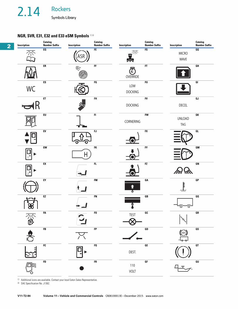
V11-T2-84 Volume 11—Vehicle and Commercial Controls CA08100013E—December 2015 www.eaton.com
2
2
2
2
2
2
2
2
2
2
2
2
2
2
2
2
2
2
2
2
2
2
2
2
2
2
2
2
2
2
2.14 Rockers
Symbols Library
NGR, SVR, E31, E32 and E33 eSM Symbols 1 2
1 Additional icons are available. Contact your local Eaton Sales Representative. 2 SAE Specification No. J1362.
InscriptionCatalog Number Suffix
EQ
ER
ES
ET
EU
EV
EW
EX
EY
EZ
FA
FB
FC
FD
1
InscriptionCatalog Number Suffix
FE
FF
FG
FH
FI
FJ
FK
FL
FM
FN
FO
FP
FQ
FR
InscriptionCatalog Number Suffix
FS
FT
FU
FV
FW
FX
FY
FZ
GA
GB
GC
GD
GE
GF
InscriptionCatalog Number Suffix
GG
GH
GI
GJ
GK
GL
GM
GN
GP
GQ
GR
GS
GT
GU

Volume 11—Vehicle and Commercial Controls CA08100013E—December 2015 www.eaton.com V11-T2-85
2
2
2
2
2
2
2
2
2
2
2
2
2
2
2
2
2
2
2
2
2
2
2
2
2
2
2
2
2
2
2.14Rockers
Symbols Library
NGR, SVR, E31, E32 and E33 eSM Symbols 1 2
1 Additional icons are available. Contact your local Eaton Sales Representative. 2 SAE Specification No. J1362.
InscriptionCatalog Number Suffix
GV
GW
GY
HA
HB
HC
HD
HE
HF
HG
HH
HJ
HK
HL
PASILLO
LUZ
InscriptionCatalog Number Suffix
HM
HN
HP
HQ
HR
HS
HT
HU
HV
HW
HY
JA
JB
JC
InscriptionCatalog Number Suffix
JD
JE
JF
JG
JH
JJ
JK
JL
JM
JN
JP
JQ
JR
JS
InscriptionCatalog Number Suffix
JT
JU
JV
JW
JX
JY
JZ
KA
KB
KC
KD
KE
KF
KG
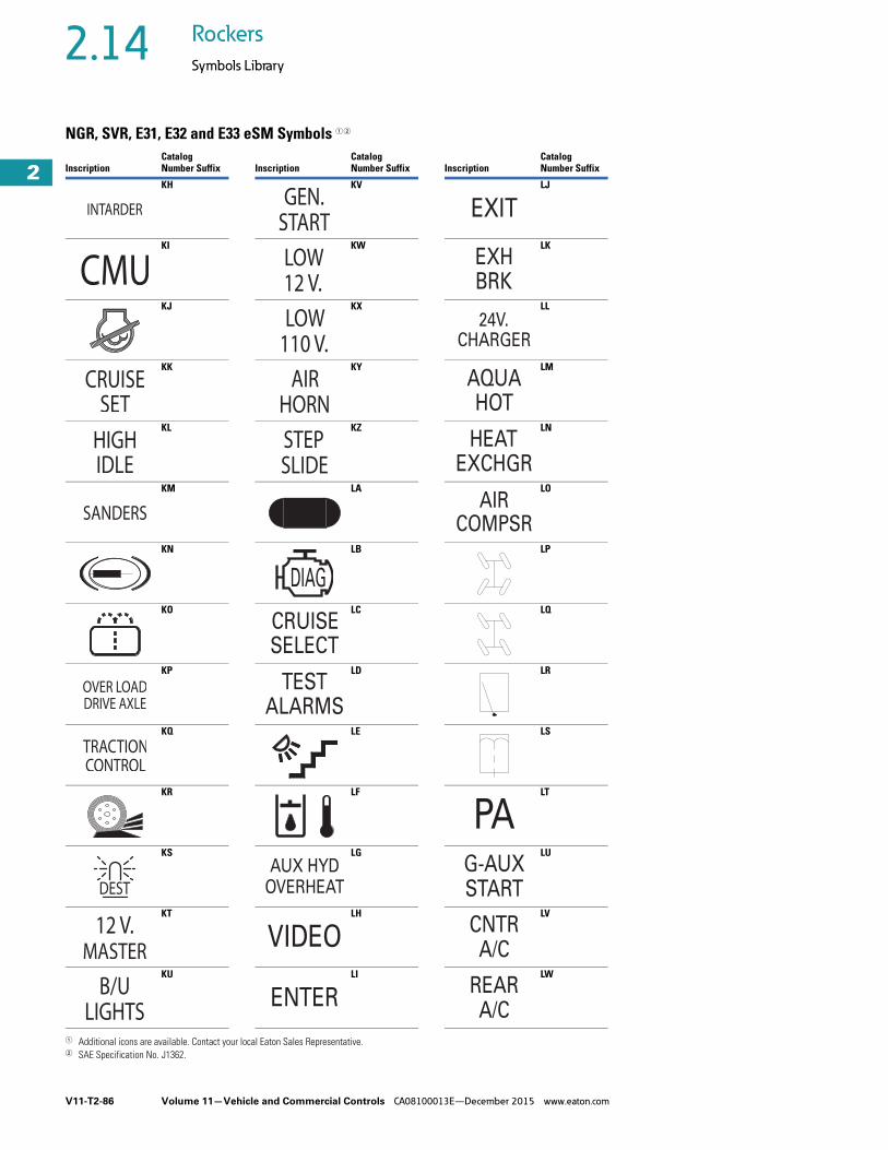
V11-T2-86 Volume 11—Vehicle and Commercial Controls CA08100013E—December 2015 www.eaton.com
2
2
2
2
2
2
2
2
2
2
2
2
2
2
2
2
2
2
2
2
2
2
2
2
2
2
2
2
2
2
2.14 Rockers
Symbols Library
NGR, SVR, E31, E32 and E33 eSM Symbols 1 2
1 Additional icons are available. Contact your local Eaton Sales Representative. 2 SAE Specification No. J1362.
InscriptionCatalog Number Suffix
KH
KI
KJ
KK
KL
KM
KN
KO
KP
KQ
KR
KS
KT
KU
InscriptionCatalog Number Suffix
KV
KW
KX
KY
KZ
LA
LB
LC
LD
LE
LF
LG
LH
LI
DIAG
CRUISESELECT
TESTALARMS
OVERHEATAUX HYD
VIDEO
ENTER
InscriptionCatalog Number Suffix
LJ
LK
LL
LM
LN
LO
LP
LQ
LR
LS
LT
LU
LV
LW
EXIT
BRKEXH
24V.CHARGER
AQUAHOT
HEATEXCHGR
AIRCOMPSR
PAG-AUXSTART
A/CCNTR
REARA/C

Volume 11—Vehicle and Commercial Controls CA08100013E—December 2015 www.eaton.com V11-T2-87
2
2
2
2
2
2
2
2
2
2
2
2
2
2
2
2
2
2
2
2
2
2
2
2
2
2
2
2
2
2
2.14Rockers
Symbols Library
NGR Only Symbols 1 2
1 Additional icons are available. Contact your local Eaton Sales Representative. 2 SAE Specification No. J1362.
InscriptionCatalog Number Suffix
LX
LY
LZ
MA
MB
MC
MD
ME
MF
MG
MH
MI
MJ
MK
DIAG
CODE
LIGHT
POSITION
MASTERWARN
UPPERWARN
LOWERWARN
COMPTLIGHTS
WORKLIGHTS
FASTIDLE
MIRRORHEAT
GENPTO
WIGWAG
SIRENBRAKE
LEFTSCENE
InscriptionCatalog Number Suffix
ML
MM
MN
MO
MP
MS
MT
MU
MV
MW
MX
MY
MZ
NA
InscriptionCatalog Number Suffix
NB
NC
ND
NE
NF
NG
NH
NI
NJ
NK
NL
NM
NN
NO
InscriptionCatalog Number Suffix
NP
NQ
NR
NS
NT
NU
NV
NW
NX
NY
NZ
PA
PB
PC

V11-T2-88 Volume 11—Vehicle and Commercial Controls CA08100013E—December 2015 www.eaton.com
2
2
2
2
2
2
2
2
2
2
2
2
2
2
2
2
2
2
2
2
2
2
2
2
2
2
2
2
2
2
2.14 Rockers
Symbols Library
NGR Only Symbols 1 2
1 Additional icons are available. Contact your local Eaton Sales Representative. 2 SAE Specification No. J1362.
InscriptionCatalog Number Suffix
PD
PE
PF
PG
PH
PI
PJ
PK
PL
PM
PN
PP
PQ
PR
InscriptionCatalog Number Suffix
PS
PT
PU
PV
PW
PX
PY
PZ
RA
RB
RC
RD
RE
RF
AXLE
OVER
DRIVELOAD
InscriptionCatalog Number Suffix
RG
RH
RI
RJ
RK
RL
RM
RN
RP
RQ
RS
RT
RU
RV
ENGINECHECK
CODEABS
InscriptionCatalog Number Suffix
RW
RX
RY
RZ
SA
SB
SC
SD
SE
SF
SG
SH
SJ
SK
D
H

Volume 11—Vehicle and Commercial Controls CA08100013E—December 2015 www.eaton.com V11-T2-89
2
2
2
2
2
2
2
2
2
2
2
2
2
2
2
2
2
2
2
2
2
2
2
2
2
2
2
2
2
2
2.14Rockers
Symbols Library
NGR Only Symbols 1 2
1 Additional icons are available. Contact your local Eaton Sales Representative. 2 SAE Specification No. J1362.
InscriptionCatalog Number Suffix
SL
SM
SN
SP
SQ
SR
SS
ST
SU
SV
SW
SX
SY
SZ
Mode
InscriptionCatalog Number Suffix
TA
TB
TC
TD
TE
TF
TG
TH
TJ
TK
TL
TM
TN
TP
InscriptionCatalog Number Suffix
TQ
TR
TS
TT
TU
TV
TW
TX
TY
TZ
UA
UB
UC
UD
InscriptionCatalog Number Suffix
UE
UF
UG
UH
UK
UL
UM
UN
UP
UR
US
UT
UU
UV

V11-T2-90 Volume 11—Vehicle and Commercial Controls CA08100013E—December 2015 www.eaton.com
2
2
2
2
2
2
2
2
2
2
2
2
2
2
2
2
2
2
2
2
2
2
2
2
2
2
2
2
2
2
2.14 Rockers
Symbols Library
NGR Only Symbols 1 2
1 Additional icons are available. Contact your local Eaton Sales Representative. 2 SAE Specification No. J1362.
InscriptionCatalog Number Suffix
UW
UX
UY
UZ
VA
VB
VC
VD
VE
VF
VG
VH
VK
VL
InscriptionCatalog Number Suffix
VM
VN
VP
VR
VS
VT
VU
VV
VW
VX
VY
VZ
WA
WB
InscriptionCatalog Number Suffix
WC
WD
WE
WF
WG
WH
WJ
WK
WL
WM
WN
WP
WR
WS
InscriptionCatalog Number Suffix
WT
WU
WV
WW
WX
WY
WZ
XA
XB
XC
XD
XE
XF
XG

Volume 11—Vehicle and Commercial Controls CA08100013E—December 2015 www.eaton.com V11-T2-91
2
2
2
2
2
2
2
2
2
2
2
2
2
2
2
2
2
2
2
2
2
2
2
2
2
2
2
2
2
2
2.14Rockers
Symbols Library
NGR Only Symbols 1 2
1 Additional icons are available. Contact your local Eaton Sales Representative. 2 SAE Specification No. J1362.
InscriptionCatalog Number Suffix
XH
XJ
XK
XL
XM
XN
XP
XR
XS
XT
XU
XV
XW
XX
InscriptionCatalog Number Suffix
XY
XZ
YA
YB
YC
YD
YE
YF
YG
YH
YJ
YK
YL
YM
InscriptionCatalog Number Suffix
YN
YP
YQ
YR
YS
YT
YU
YV
YW
YX
YY
YZ
ZA
ZB
InscriptionCatalog Number Suffix
ZC
ZD
ZE
ZF
ZG
ZH
ZJ
ZK
ZL
ZM
ZN
ZP
ZR
ZS

V11-T2-92 Volume 11—Vehicle and Commercial Controls CA08100013E—December 2015 www.eaton.com
2
2
2
2
2
2
2
2
2
2
2
2
2
2
2
2
2
2
2
2
2
2
2
2
2
2
2
2
2
2
2.14 Rockers
Symbols Library
NGR Only Symbols 1 2
1 Additional icons are available. Contact your local Eaton Sales Representative. 2 SAE Specification No. J1362.
InscriptionCatalog Number Suffix
ZT
ZU
ZV
ZW
ZX
ZY
ZZ
A1
B1
C1
D1
E1
F1
G1
InscriptionCatalog Number Suffix
H1
J1
K1
L1
M1
N1
P1
R1
S1
T1
U1
V1
W1
X1
InscriptionCatalog Number Suffix
Y1
Z1
A2
B2
C2
D2
E2
F2
G2
H2
J2
K2
L2
M2
InscriptionCatalog Number Suffix
N2
P2
R2
S2
T2
U2
V2
W2
X2
Y2
Z2
A3
B3
C3

Volume 11—Vehicle and Commercial Controls CA08100013E—December 2015 www.eaton.com V11-T2-93
2
2
2
2
2
2
2
2
2
2
2
2
2
2
2
2
2
2
2
2
2
2
2
2
2
2
2
2
2
2
2.14Rockers
Symbols Library
NGR Only Symbols 1 2
1 Additional icons are available. Contact your local Eaton Sales Representative. 2 SAE Specification No. J1362.
InscriptionCatalog Number Suffix
D3
E3
F3
G3
H3
J3
K3
L3
M3
N3
P3
Q3
R3
S3
InscriptionCatalog Number Suffix
T3
U3
V3
W3
X3
Y3
Z3
A4
B4
C4
D4
E4
F4
G4
InscriptionCatalog Number Suffix
H4
J4
K4
L4
M4
N4
P4
R4
S4
T4
U4
V4
W4
X4
InscriptionCatalog Number Suffix
Y4
Z4
A5
B5
C5
D5
E5
F5
G5
H5
J5
K5
L5
M5

V11-T2-94 Volume 11—Vehicle and Commercial Controls CA08100013E—December 2015 www.eaton.com
2
2
2
2
2
2
2
2
2
2
2
2
2
2
2
2
2
2
2
2
2
2
2
2
2
2
2
2
2
2
2.14 Rockers
Symbols Library
NGR Only Symbols 1 2
1 Additional icons are available. Contact your local Eaton Sales Representative. 2 SAE Specification No. J1362.
InscriptionCatalog Number Suffix
N5
P5
Q5
R5
S5
T5
U5
V5
W5
X5
Y5
Z5
A6
B6
InscriptionCatalog Number Suffix
C6
D6D6
E6
F6
G6
H6
J6
K6
L6
M6
N6
P6
Q6
R6
InscriptionCatalog Number Suffix
S6
T6
U6
V6
W6
X6
Y6
Z6
A7
B7
C7
D7
E7
F7
InscriptionCatalog Number Suffix
G7
H7
J7
K7
L7
M7
N7
P7
Q7
R7
S7
T7
U7
V7

Volume 11—Vehicle and Commercial Controls CA08100013E—December 2015 www.eaton.com V11-T2-95
2
2
2
2
2
2
2
2
2
2
2
2
2
2
2
2
2
2
2
2
2
2
2
2
2
2
2
2
2
2
2.14Rockers
Symbols Library
NGR Only Symbols 1 2
1 Additional icons are available. Contact your local Eaton Sales Representative. 2 SAE Specification No. J1362.
InscriptionCatalog Number Suffix
W7
X7
Y7
Z7
A8
B8
C8
D8
E8
F8
G8
H8
J8
K8
InscriptionCatalog Number Suffix
L8
M8
N8
P8
Q8
R8
S8
T8
U8
V8
W8
X8
Y8
Z8
InscriptionCatalog Number Suffix
A9
B9
C9
D9
E9
F9
G9
H9
J9
K9
L9
M9
N9
P9
InscriptionCatalog Number Suffix
Q9
R9
S9
T9
U9
V9
W9
X9
Y9
Z9
1A
1B
1C
1D

V11-T2-96 Volume 11—Vehicle and Commercial Controls CA08100013E—December 2015 www.eaton.com
2
2
2
2
2
2
2
2
2
2
2
2
2
2
2
2
2
2
2
2
2
2
2
2
2
2
2
2
2
2
2.14 Rockers
Symbols Library
NGR Only Symbols 1 2
1 Additional icons are available. Contact your local Eaton Sales Representative. 2 SAE Specification No. J1362.
InscriptionCatalog Number Suffix
1E
1F
1G
1H
1J
1K
InscriptionCatalog Number Suffix
1L
1M
1N
1P
1Q
1R
InscriptionCatalog Number Suffix
1S
1T
1U
1V
1W
1X
InscriptionCatalog Number Suffix
1Y
1Z
2A
2B
2C

Volume 11—Vehicle and Commercial Controls CA08100013E—December 2015 www.eaton.com V11-T2-97
2
2
2
2
2
2
2
2
2
2
2
2
2
2
2
2
2
2
2
2
2
2
2
2
2
2
2
2
2
2
2.14Rockers
Symbols Library
SVR, E31, E32 and E33 eSM Symbols 1 2
1 Additional icons are available. Contact your local Eaton Sales Representative. 2 SAE Specification No. J1362.
InscriptionCatalog Number Suffix
LX
LY
MA
MB
MC
MD
ME
MF
MG
MH
MI
MJ
MK
ML
2
HIRPM
LOWRPM
TEST
P
RSM/ACC
InscriptionCatalog Number Suffix
MM
MN
MP
MQ
MR
MS
MT
MU
MV
MW
MX
MY
MZ
NA
SET/CST
SHDN
OVRD
EXHST
BRK
P
InscriptionCatalog Number Suffix
NB
NC
ND
NE
NF
NG
NH
NJ
NK
NL
NM
NN
NP
NQ
FNAUX
WARN
LOADOVER
InscriptionCatalog Number Suffix
NR
NS
NT
NU
NV
NW
NX
NY
NZ
O3
PA
PB
PC
PD

V11-T2-98 Volume 11—Vehicle and Commercial Controls CA08100013E—December 2015 www.eaton.com
2
2
2
2
2
2
2
2
2
2
2
2
2
2
2
2
2
2
2
2
2
2
2
2
2
2
2
2
2
2
2.14 Rockers
Symbols Library
SVR, E31, E32 and E33 eSM Symbols 1 2
1 Additional icons are available. Contact your local Eaton Sales Representative. 2 SAE Specification No. J1362.
InscriptionCatalog Number Suffix
PE
PF
PG
PH
PI
PJ
PK
PL
PM
PN
PP
PQ
PR
PS
AUTO
AUTO
n/min
n/min
InscriptionCatalog Number Suffix
PT
PU
PV
PW
PX
PY
PZ
QA
QB
QC
QD
QE
QF
QG
AUTO
AUTO
AUTO
InscriptionCatalog Number Suffix
QH
QJ
QK
QL
QM
QN
QP
QR
QS
QT
QU
QV
QW
InscriptionCatalog Number Suffix
QX
QY
QZ
RA
RB
RC
RD
RE
RF
RG
RH
RJ
RK
RL
ACCELSET
DECELRESUME
CTIS
WINCH
CRANE
MODEAUTO
MANMODE

Volume 11—Vehicle and Commercial Controls CA08100013E—December 2015 www.eaton.com V11-T2-99
2
2
2
2
2
2
2
2
2
2
2
2
2
2
2
2
2
2
2
2
2
2
2
2
2
2
2
2
2
2
2.14Rockers
Symbols Library
SVR, E31, E32 and E33 eSM Symbols 1 2
1 Additional icons are available. Contact your local Eaton Sales Representative. 2 SAE Specification No. J1362.
InscriptionCatalog Number Suffix
RM
RN
RP
RQ
RR
RS
RT
RU
RV
RW
RX
RY
RZ
SA
InscriptionCatalog Number Suffix
SB
SC
SD
SE
SF
SG
SH
SJ
SK
SL
SM
SN
SP
SQ
ENGDIAG
InscriptionCatalog Number Suffix
SR
SS
ST
SU
SV
SW
SX
SY
SZ
TA
TB
TC
TD
TE
InscriptionCatalog Number Suffix
TF
TG
TH
TJ
TK
TL
TM
TN
TP
TQ
TR
TS
TT
TU
RPMCTRL
ALARMCHEM

V11-T2-100 Volume 11—Vehicle and Commercial Controls CA08100013E—December 2015 www.eaton.com
2
2
2
2
2
2
2
2
2
2
2
2
2
2
2
2
2
2
2
2
2
2
2
2
2
2
2
2
2
2
2.14 Rockers
Symbols Library
SVR, E31, E32 and E33 eSM Symbols 1 2
1 Additional icons are available. Contact your local Eaton Sales Representative. 2 SAE Specification No. J1362.
InscriptionCatalog Number Suffix
TV
TW
TX
TY
TZ
UA
UB
UC
UD
UE
UF
UG
UH
UJ
InscriptionCatalog Number Suffix
UK
UL
UM
UN
UP
UQ
UR
US
UT
UU
UV
UW
UX
UY
P
F
LH
RH
InscriptionCatalog Number Suffix
UZ
VA
VB
VC
VD
VE
VF
VG
VH
VJ
VK
VL
VM
VN
InscriptionCatalog Number Suffix
VP
VQ
VR
VS
VT
VU
VV
VW
VX
VY
VZ
WA
WB
WC
FAU
LTO
K
AUTO

Volume 11—Vehicle and Commercial Controls CA08100013E—December 2015 www.eaton.com V11-T2-101
2
2
2
2
2
2
2
2
2
2
2
2
2
2
2
2
2
2
2
2
2
2
2
2
2
2
2
2
2
2
2.14Rockers
Symbols Library
SVR, E31, E32 and E33 eSM Symbols 1 2
1 Additional icons are available. Contact your local Eaton Sales Representative. 2 SAE Specification No. J1362.
InscriptionCatalog Number Suffix
WD
WE
WF
WG
WH
WJ
WK
WL
WM
WN
WP
WQ
WR
WS
InscriptionCatalog Number Suffix
WT
WU
WV
WX
WY
WZ
XA
XB
XC
XD
XE
XF
XG
XH
InscriptionCatalog Number Suffix
XJ
XL
XM
XN
XP
XQ
XR
XS
XT
XU
XV
XW
XY
XZ
InscriptionCatalog Number Suffix
YA
YB
YC
YD
YE
YF
YG
YH
YJ
YK
YL
YM
YN
YP
SET/RES

V11-T2-102 Volume 11—Vehicle and Commercial Controls CA08100013E—December 2015 www.eaton.com
2
2
2
2
2
2
2
2
2
2
2
2
2
2
2
2
2
2
2
2
2
2
2
2
2
2
2
2
2
2
2.14 Rockers
Symbols Library
SVR, E31, E32 and E33 eSM Symbols 1 2
1 Additional icons are available. Contact your local Eaton Sales Representative. 2 SAE Specification No. J1362.
InscriptionCatalog Number Suffix
YQ
YR
YS
YT
YU
YV
YW
YX
YY
YZ
ZA
ZB
ZC
ZD
InscriptionCatalog Number Suffix
ZE
ZF
ZG
ZH
ZJ
ZK
ZL
ZM
ZN
ZP
ZR
ZS
ZT
ZU
InscriptionCatalog Number Suffix
ZV
ZW
ZX
ZY
ZZ
A1
B1
C1
D1
E1
F1
G1
H1
J1
RPM
RPM
InscriptionCatalog Number Suffix
K1
L1
M1
N1
P1
R1
S1
T1
U1
V1
W1
X1
Y1
Z1

Volume 11—Vehicle and Commercial Controls CA08100013E—December 2015 www.eaton.com V11-T2-103
2
2
2
2
2
2
2
2
2
2
2
2
2
2
2
2
2
2
2
2
2
2
2
2
2
2
2
2
2
2
2.14Rockers
Symbols Library
SVR, E31, E32 and E33 eSM Symbols 1 2
1 Additional icons are available. Contact your local Eaton Sales Representative. 2 SAE Specification No. J1362.
InscriptionCatalog Number Suffix
A2
B2
C2
D2
E2
F2
G2
H2
J2
K2
L2
M2
N2
P2
InscriptionCatalog Number Suffix
R2
S2
T2
U2
V2
W2
X2
Y2
Z2
A3
B3
C3
D3
F3
InscriptionCatalog Number Suffix
G3
H3
I3
J3
K3
L3
M3
N3
O3
P3
Q3
R3
S3
T3
InscriptionCatalog Number Suffix
U3
V3
W3
X3
Y3
Z3
A4
B4
C4
D4
E4
F4
G4
H4

V11-T2-104 Volume 11—Vehicle and Commercial Controls CA08100013E—December 2015 www.eaton.com
2
2
2
2
2
2
2
2
2
2
2
2
2
2
2
2
2
2
2
2
2
2
2
2
2
2
2
2
2
2
2.14 Rockers
Symbols Library
SVR, E31, E32 and E33 eSM Symbols 1 2
1 Additional icons are available. Contact your local Eaton Sales Representative. 2 SAE Specification No. J1362.
InscriptionCatalog Number Suffix
I4
J4
K4
L4
M4
N4
O4
InscriptionCatalog Number Suffix
P4
Q4
R4
S4
T4
U4
InscriptionCatalog Number Suffix
V4
W4
X4
Y4
Z4
A5
InscriptionCatalog Number Suffix
B5
C5
D5
X5
X6
X7