volume 2 aerial videography - irdhorizon.documentation.ird.fr/exl-doc/pleins_textes/doc34... ·...
TRANSCRIPT

VOLUME 2
AERIAL VIDEOGRAPHY
Principles and implementation
Marc Souris
Institut de Recherche pour le Developpement
UNHCR-IRD
October 1999
97/TF/ KEN/ LS/ 450(a$

Foreword
TIùs document outlines the principles of acquiring aerial data using digital videography. It describesthe implementation of this method, the preparation of a flight for images acquisition and the integrationof the aerial mosaic in a geograplùcal information system (SAVANE). An executive summary gives aquick look of the method and results. A detailed technical guideIine describes aIl the operations. Theexample highIighted throughout this document is on the refugee camps of Kenya, in which this methodof acquiring images has been used to come up with a precise cartography of the camps.
Amal Videography - UNHCR-IRD(ex-Orslom), 1999
2

Acknowledgements
Yvette Stevens - UNHCR Representative, Nairobi - KenyaAlan Peters - UNHCR, Director CEW A, Ceneva - SwitzeriandDaniel Tshitungi - UNHCR, Deputy, Nairobi - KenyaSajaad Malik - UNHCR, Planning Officer, Nairobi - KenyaJavier Lopez CifL/entes - UNHCR, Senior Programme Officer, Nairobi - KenyaCollin Asare - UNHCR, Head of Sub Office, Dadaab - KenyaSaber Azam - UNHCR, Head of Sub Office, Kakuma - KenyaYuji Kimura - UNHCR, Environment Unit, Ceneva - SwitzerlandJean- Yves Bouchardy - UNHCR, Environment UTÙt, Ceneva - SwitzeriandMoshood Olatokunbo - UNHCR, Desk Officer for Kenya, Ceneva - SwitzeriandReinier Thiadel1s - UNHCR, Senior Agricultural Planning Officer, Ceneva - Switzeriand
Ail the UNHCR staff in Dadaab and Kakuma (Kenya), for the reception in the camps and the logis ticsplaced at our disposaI (authorisations, cars, drivers, and escorts).
For the technical aspects of this study :
Sylvain Bonvallot (geophysical, !RD Centre Ile-de-France), for his advisement on positioning by CPSFor our applications of positioning, we could use the CPS of the !RD geophysics department,
Luc Cambrezy (geography, IRD), person in charge for the !RD of the program on the refugees. LucCambrezy took part directly in the tests of catch of sight, the development of the flights, and the catch ofsight on the refugee camps of Kenya. He carried out the aerial mosaics for the camps of Ho, Dagahaleyand Hagadera,
Damien Chaminade (CSN, Nairobi), for his assistance at the time of the catch of point crs in Kenya andfor its participation in the mosaic process,
Jean Cheneau (IRD, Centre [Je-de-France), for the construction of the fixing of the camera,Jean-Louis Janeau (soil sciences, !RD, Quito), who took part in the first tests of embarked video camera
in Qui to (Ecuador),Gad N Kamau (chief pilot, Nairobi) of the airline company (2 Boskovic Air Ltd Charter.), for its availa
bility and its high competence,Bernard Lortie (cartography and remote sensing, IRD, Centre Ile-de-France), for his councils and his
assistance (taken of sight, geometrical correction of the images),Envan Moreau (audio-visual, IRD, Centre Ile-de-France), as weil as the audio-visual workshop, for its
advice, the assistance practises workshop and the loan of audio-visual material (camera and accessories),Pierre Peltre, person in charge of the Applied Cartography Laboratory of the IRD, for its support, its
councils, and practical assistance of the laboratory of cartography,Laurence Quinn;-Bourgeois (Applied Cartography Laboratory) for her support in various edition pro
cesses.Dominique Remy (data processing, !RD, Centre lle-de-France), for his participation in the development
of the Savane system.
Amal Vldeograpl,y - UNHCR-IRD(ex-OrslolJ/), 1999
3

Contents
Executive Summary 5Aerial Videography and cartography of the Refugee camps in Kenya 5
Technical Guideline 7Generalities 7
Light air remote sensing : many applications 7Aerial Videography : general principles 7Actual methods of acquiring remote sensing images in the visible spectrum 8Aerial videography : principles and techniques 9Materials and software required implementing aerial videography IlCost evaluation 11Perspectives 12
Planning an Aerial Videography Exercise 13Defuùtion of Objectives of the Survey : Territory, Resolution, Accuracy 13Infrastructure 16Authority and Weather conditions 16Preparation of the equipment on the spot 16
Preparation for Filming 18Aerial navigation 18Preparing a flight plan 18Examples 21
Aerial Filming : Flying over 27Types of light aircraft : Characteristics 27Preparing the equipment 27Checking the Camera 29During the Flight 29Monitoring the flight 30
Taking Geographie Positions on the field by differential GPS 34Objectives 34Geodesy and Cartography 34GPS background 34Differential Positioning using GPS 35The equipment 36Example: Taking the points in the field 36
Capture of fixed images 40The Principle of the Digital videography 40The m.iniDV format. 40Capture of fixed images 40
Adjustment, Correction and Mosaic 43Distortions and Adjusbnents 43Re-sampling 44The AdJusting Exercise 44Introduction of the mosaic in a GIS 46
Using a Geographical Information System 52Geographical Information System background 52Mosaics management 52Digitization on the Mosaic 52
Bibliography 54
4

Executive Summary
Aerial Videography and cartography of the Refugee camps in Kenya
The method of air data acquisition trough numerical videography suggested in this document makespossible to obtain aerial images with a possible resolution (i.e. size of a pixel, element of image) variablefrom 3 meters to 0.2 meters. It is located thus between the resolution of the current civil satellites of observation most powerful and traditional aerial photography. The developed method aims answeringconstraints often met in the developing countries, to minimise the deadlines, the costs and the infrastructure necessary to the catch of air sight.
The light air remote sensing meets many technical needs: basic cartography, cartography of soil usingon a large scale, thematic cartography, sampling, updating, etc. Many disciplines are concemed by thesetechniques: one can quote hydrology (irrigation and water stock management), environment and naturalresources management, rural development, urban development, land tenure ...
The principles of the method presented in this document are the following : after having prepared adetailed flight plan (2), the overflight by light plane with a numerical video camera and directed towardsthe ground in a roughly orthogonal way (3) makes it possible to have a video film covering wished surface, by parallel traces with a certain overlap between traces (4). From numerical video film, one can extract directly digital images and download them on a computer. The user has the choice of the images to capture : he must oruy ensure himself of the correct overlap between the images and their best horizontality.
Mer downloading the images on a computer (6), it is necessary to find points of geographical reference to locate, readjust and rectify the images in order to eliminate the deformations due to the catch fromsight (optical deformations, horizontality, altitude). One associates position of a point in the capturedimage and real geographical position to create points of landmark. The real geographical position can begiven directly by GPS on the ground (5), or on an already readjusted and positioned photograph, on achart, etc. Lastly, thanks to the landmarks, the captured images are rectified (i.e. put in geographicalconformity), readjusted (i.e. positioned in space), then joined (7) (i.e. integrated in a whole of images) toconstitute a geo-referred mosaic (8). This mosaic is integrated in a geographical information system, whichmakes it possible in its tum to use the mosaic as a basic map for later work (9) (digitisation, representation, thematic cartography, etc.).
The method described above was used to carry out the cartography of the refugee camps in Kenya(Kakuma, Dadaab), within the framework of the research agreement on the refugees being the subject ofa convention between the UNlfCR and the IRD (ex-OR5TOM).
Many difficulties were joined together on this site: difficult access (the camps are far away from thegreat agglomerations), unstable weather conditions (El Nilio consequencies), lack of cartography to largeand average scale, logistical difficulties, security concem, etc. Nevertheless, the method of catch of sightwas effective in spite of these difficult conditions: we thus could carry out geo-referenced mosaics of thefour refugee camps of Kenya: Kakuma, lio, Dagahaley, Hagadera. The method as well as the results obtained are presented in the second part of this document.
Aerial Videography - UNHCR-TRD(ex-Orstom), 1999
5

Flight plan GPS survey (4)
DOWTÙoading the pictures (6)
Global mosaic (8)
6
Hagadera's flight plan (2)
Field GPS survey (5)
«Mosaiquing» (7)
Digitisa lion on the screen (9)
Aerial Videography - UNHCR-IRD(er-Orstom), 1999

Technical Guideline
Chapter 1
Generalities
From aerial photography to satellite images, many are the methods to obtain earth images troughremote sensing techniques. The method of aerial images acquisition trough numerical videography suggested in this document makes possible to obtain aerial images with a possible resolution (i.e. size of apixel, element of image) variable from 3 meters to 0.2 meters. Il is located thus between the resolution ofthe current civil satellites of observation most powerfui and traditional aerial photography. The developed method aims answering constraints often met in the developing countries, to minimise the deadlines,the costs and the infrastructure necessary to the catch of air sight.
1bis development of this method of acquisition falls under methodological research of GeographicalInformation Systems (GIS) : it is comprised of development of methods and software for the setting up,«mosaiquing» and integrated management and processing of the images data in a GIS (SAVANE). In thisguide, aIl stages of methodology, acquisition of images to their integration in a geographical informationsystem are explained.
1bis method of acquiring images was used in Kenya, under the IRDjUNHCR co-operation programme on refugees. 1bis guide gives a detailed description of the example, which al50 puts together severaldifficulties in implementation (accessibility, security, infrastructure, and climate.).
Light air remote sensing : many applications
The light remote sensing methods relates to all the techniques a.i.nting at obtaining air images of theEarth by air trough accessible tool5 easy to carry on. Il completes thetraditional air photography and satellite images.
The light air remote sensing meets many technical needs : basic cartography, cartography of soil usingon a large scale, thematic cartography, sampling, updating, etc. Many disciplines are concerned by thesetechniques: one can quote hydrology (irrigation and water stock management), environment and nal:uralresources management, rural development, urban development, land tenure ...
To achieve a light air remote-sensing programme, one needs an apparatus of catch of sight (camera)and a mean of transport of this apparatus. Among the means of transport, one can quote : light singleengine airerait, helicopters, UlM, drones (planes without pilots), balloons, airships and Montgolfiers. Theapparatuses of catches of sight form two groups: on the one hand traditional optical cameras, on the otherhand numerical captors. The method presented in this document - the aerial videography - uses a numerical video camera embarked on a light aircrait or an ULM.
Aerial Videography: General Principles
The general principle of aerial videography is as follows :
After preparing a precise flight plan, flying using a low airplane with a digital camera, directedtowards the ground in an approximately orthogonal manner enables one to have a video film covering thedesired area in parallel tracks with an overlap between the tracks. The user chooses which images todownload: he must only be sure of the images overlap and ensure proper seating on the airplane.
After the (optional) printing of the images on paper, it is necessary to identify points of geographicalreference to confine, correct and set up and thus exclude deformations during shooting (as a result poor
Amal Videography - UNHCR-IRD(ex-Orstom), 1999
7

seating position on the flight or optical deformations). The position of a point in a captured image and thereal geographical position are associated to create the landmark points. The real geographical position canbe determined directly by the GPS on the ground or from photography already mounted and positioned,on a map, etc. Finally, using the landmark points, the captured images are set up (that is, put in geographical conformity), mounted (that is, positioned in space) and then integrated into the entire images toconstitute a geo-referenced mosaic.
We will first situate this method within the general context of the methods of acquiring images invisible spectrum.
Actual methods of acquiring remote sensing images in the visible spectrum
Today (1999), it does exist many performing methods of acquiring images on the Barth using civilremote sensing techniques in the visible spectrw:n. By order of resolution (height of pixel, element ofimage), they are :
• Satellites with Low Resolution (height of highest pixel up to 500 meters)• Satellites with Medium Resolution (height of pixel between 500 and 50 meters)• Satellites with High resolution (height of pixel between 50 and 5 meters)• Satellite with very high resolution (height of lower pixel- to 5 meters)• Aerial videography (height of lowest pixel 3 meters)• Aerial Photography
Aerial videography enables one to obtain resolutions varying between 3 and 0.2 meters. Satellites withlow and medium resolution do not fail in this field of operation. Civil satellite images in high resolutionhave a resolution that can attain 2 meters, but the most current images are those of the SPOT satellite (10meters in panchromatic mode, 20 meters in multi-spectral mode). The cost is between 0.3 USD/km2 forLandsat (one image cover 34000 km2) and 0.6 USD/km2 for Spot (an imagecover about 3600 km2). Othersatellites with high resolution (between 5 and 1 meter) will definitely be introduced in the years to come(2000-2005), and could thus make obsolete the technique of acquisition trough numerical videography ;UIÙess the flexibility of the method, the speed of obtaining of the result and the increase in resolution ofthe video sensors do not continue to make it competitive.
Of ail the methods of acquisition, classical aerial photography remains the best as pertains to resolution : a scanned aerial photograph enables one to have a resolution much lower than a meter. On thecontrary, cost is an important factor (from 50 $/km2 for a 1000 km2 survey) and implementing an aerialphotography campaign cails for the use of heavy means. Since the principal criteria is the resolution andthat there already exists a recent aerial photography cover, it is preferable to buy and then scan the photographs than take an aerial view again using another method. Often, the colour is missed out: most ofthe aerial photographs are in black and white.
Thus, aerial videography enables the classical aerial photography and us to ensure the continuity ofthe resolutions between the high-resolution satellite images. We can develop a comparative matrix of thediverse methods using various criteria:
resolution availability (ost meleorology Duration
Satellite from 30 m Ioepends of the satellite From sorne days to0.3 à 0.6 USD/km2 No c10udsto 2m ~d rneteorological sorne rnonths
onditions
Videographyfrom 30 m lMust he rnanaged: light No clouds Wlder Sorne daysto 0.2m ~craft, video-camera, 5 à 20 USD/km2
the flight plan~PS leveJ
Aerial Ioassical aerial No clouds Wlderphotographs Up to 0.1 m 10 à 50 UDS/km2 From sorne days
IPhotograph the flight plan to sorne weekstechniques level
Aerin/ ViJleography - UNHCR-IRD(ex-Orstom), 1999
8

1. Landsat TM (30 meters resolution)
3. Panchromatic SPOT (10 meters resolution)
2. SPOT XS (20 meters resolution)
4. Videography (1 meter resolution)
Fig 1: Examples of images from the same area with different resolutions: Satellite Landsat (30 meters), SPOT Multi-specrral (20 meters), SPOT panchromatic (10 meters), videography (1 meter).
Aerial Videography : Principles and Techniques
Aerial videography uses many techniques whose principles are worth Wlderstanding : geodesy andcartography, accurate aerial navigation, digital videography, positioning by differential GPS, correctionand re-sampling of images, mosaiquing and geographical information systems.
Geodesy and CartographyTo represent a point on the Earth, a simple mathematical surface, which is close ta the real shape of the
earth is used. This surface has the shape of a revolution ellipsoid and enables to represent the position ofa point using spherical co-ordinates : longitude, latitude, altitude in relation to the surface of the ellipsoid.Practically, several sizes and positions of the ellipsoids are used : it is necessary to be careful with the parameters used (the datum).
Aerial Videography - UNHCR-IRD(ex-Orstom), 1999
9

To represent a piece of this curvilinear surface on a fiat surface, we use cartographic projection exercise, which deforms the curvilinear surface and projects it on a two-dimension plan.
Aerial NavigationTo ensure proper covering of the area to be represented on the map, it is necessary to inform the pilot
of the light aircraft, the total number of parameters in order to enable him undertake an accurate navigation. A flight plan should be made using geographical co-ordinates of entry and exit points of the tracks(navigation is then done by GPS following an orthonomy, lines of the shortest curvilinear distance between two points of the same altitude), or using an entry point and a cape (navigation is then done by compass according to a loxodromy provided that the vertical stability of the aircraft is taken into account).
The Principle of Videography and the miniDV Digital FormatA video film is made up of consecutive images (frames) at the rate of 50 (PAL, SECAM) or 60 (NTSC)
images per second. Each frame corresponds to the scarming of one line out of two on the screen, which intum enables one to have a full image every 1/25th (PAL, SECAM), or 1/30th (NTSC) of a second and tomake sure that there is a better result of the motion (it is said that the images are intertwined, with bothodd and even frames). The miniDV digital video format is made up of 720*576 pixels for each frame.
Acquiring a Fixed ImageAn image can be captured from two consecutive frames of the video film, in order to obtain a fixed
image. Using digital coding of the signal and DV format resolution, the fixed images are of excellent quality and cannot be obtained when using a video camera, which has almost the same format as the Hi8.
If the speed of the object to be filmed in relation to the video camera is high, two consecutive frames(distance of 1/50th or 1/60th of a second) will show big differences and the fixed image will be constituted from one of the two frames only due to a minor interpolation between the lines.
The Principle of Differential GPSThe GPS system (Global Positioning System) is a system of global positioning using satellite, enabling
one to calculate the position of any point whatsoever on the Earth, in the three dimensions.Simultaneously, the GPS system enables the aircraft to have an aceuracy of 100 metres, the measurementsbeing obscured by several factors: error on the orbital parameters of the satellite, errors on the satellitedock, errors of propagation of signals due to weather conditions and to the satellite positions, error fromthe radio dock, errors of reception due to reflections of the signal, voluntary degradation of the signal bythe Deparbnent of Defence of USA (who manage the system).
To locate one's position with an accuracy corresponding to the resolution of the image, it is necessaryto take the measurements with relative accuracy among all the points less than a meter. This accuracy canbe obtained using the differential GPS.
Adjusting and re-sampling of imagesIn determining the correspondence between the points of the image and the points localised geogra
phically (using landrnarks), one can calculate the modifications to put on the image to make it coneur withthe geographical reality following a given geographical projection. With two landmarks, a rotation can becarried out followed by a translation. With three landmark points, a polynomial distortion of 1degree canbe carried out. With severallandrnark points, a local adjusting can be done by covering 1-degree distortion in each triangle emerging from triangulation between the landmark points.
Re-sampling enables one to modify the resolution in the arranged image by choosing the pixels to takeinto account in the original image in order to calculate the value of an arranged pixel in the target image.
Mosaïquing and Geographical Information SystemsFrom the rectified images, integrating the pixels of the adjusted images into one whole can constitute
one big image. The structure of a mosaic is more complex than that of a simple image because mosaic doesnot necessarily have the shape of a rectangle. Mosaics are managed by geographical information systems.These systems enable one to manage other types of geographical data (polygons,lines, points) and to compare among them these different data types.
Amal Videography - UNHCR-lRD(ex-Orslom), 1999
10

Materials and software required implementing aerial videography
Materials required :• Digital video camera that can capture fixed images on a computer (SONY type DCR-VX1000E with
a DVBK2000E target for capturing image on a computer)• A waterproof battery 12V7VAH (minimum), a battery charger 12V and a special12V cable for the
camera• Special mounting that enables to set the camera vertically outside the aircraft with device for adjus
ting the seating and inclination• An adjustment instrument for the focal distance (for cameras with different focal distance that does
not show the actual focal distance)• Altematively, a small12 V control monitor equipped with a video input• Two GPS enabling differential measurements for relative positioning of less than a meter (MAGEL
LAN PROMARK X CM type)• Two professional antennae with a tripod for the GPS• A computer to charge the measurements from the GPS (an exercise to he undertaken every hall day)
to doWIÙoad images from the camera, to rectify, resample, mosaic them and use the mosaic
Required SoftwareSoftware for acquiring fixed images (supplied with the camera or capture card),Software for calculating differential positions for GPS points (supplied with GPS),Software for preparing a flight, to rectify the images and to mosaic them,Geographical information system that works with mosaic or a large volume of images.
The SAVANE geographical information system was used for all the exercises presented in this document.
Cost evaluation
To evaluate the total cost of the aerial videography exercise, we will need to aggregate an estimatedcost of the materials and software, the costs of infrastructure (hiring an aircraft), manpower costs (basingon the expertise rate of the Institute) and overall transport costs.
Material and SoftwareFilming: 4,200 $ (camera), 700 $ (capture), control monitor (170 $), other equipment's (170 $)Differential GPS : two units (20,000 $), two antennae (2,500 $), tripod (340 $)Lap Top: 4,200 $Software: depends on the GIS used (2,000 $ for the SAVANE system)The total estimated cost for the purchase of material and software is 33,000 $. Expecting depreciation
in costs within three years, at the rate of 4 exercises by year, depreciation per exercise can he estimated at1,700 $ (the same is al50 expected of GPS and Computer on other exercises). Without the GPS, depreciation falls below 800 $.
Preliminary maps and DataMaps, satellite images or aerial photographs (a Panchro SPOT scene costs between 1,000 and 2,800 $).
FilmingCost of fieldwork for a few days by an engineer (170 $/ day).Hiring an aircraft with a pilot (hetween 170 and 670 $/hour).
Countryside CPS ExerciseCost of a field exercise for several days by an engineer or technician (170 $/day).
Capture and sampling of ImagesThis depends on the numher of images (about 30 images/ day per operator) (lKF/ day).This cost of fuis exercise therefore varies between 3,300 and 17,000 $ to wruch transport costs must he added.
Aerial Videography - UNHCR-IRD(ex-Orstam), 1999
11

Perspectives
Digital photography is undergoing rapid change, and especially with increase of cheap high-resolutionvideo cameras (1999, cameras with a resolution higher than 1.3 MegaPixels for an image with a resolutionof 1600*1200). If the principles remain valid, the camera can he adequately replaced by a high resolutionfilming equipment that enables the capture and storage of digital images in a magnetic form within a shorttime, at a rate compatible to the needs of aerial filming (almost one image per second). This tedmologywould enable one to make filming much easier and to increase the resolution tremendously.
Amal Videography - UNHCR-IRD(ex-Orstam), 1999
12

Chapter 2
Planing an Aerial Videography Exercise
Like in the case of aerial photography, it is important to draw an advance plan of ail the steps ta beundertaken in an aeria1 videography exercise. This plan entails :
• definition of objectives (area to he covered, required resolution)• Available infrastructure for filming and extraction of landmark points (accessibility, secu.rity, road
ground, available aerial transport)• VVeatherforecast• Flying rights for the area to be covered• Preparing the material on the spot• Cost evaluation for the entire expected exercise (flight, extraction of points using GPS, existing maps,
sampling, GIS)
Definition of Objectives of the Survey : Territory, Resolution, and Accuracy
The area to be covered must be accurately defined. Basic existing maps must he used in this definition.If the area to be covered is not on the map, a geographical description is important: GPS points, singleelements, etc. A satellite image, even with a medium resolution is useful in the preparatory phase.
The required resolution must he defined at this stage of the project. The result of aeria1 videography isa digital image, made up of pixels (elements of the image). The resolution is equiva1ent to the relativeaccuracy of the pixels in the image. Giving a resolution is thus giving a size to a pixel (if a resolution isone meter, then this means the pixel is one meter big).
The resolution is fixed depending on the minimum size of the objects which must be visible in theimage (if it is estimated that four pixels will be required in each dimension to recognise a car in an image,and that the car measures at least 4 metres long, then a resolution is required to see the car in the image).To fix the resolution, one must evaluate the accuracy by identifying the objects, which must he visible inthe image by their real size, as weil as the number of pixels required to represent them adequately.
Absolute accuracy corresponds to the accuracy of the geographicallocation of each pixel (in the geographical projection used). This absolute accuracy must equally be eva1uated at this stage, because planning of the exercise of extracting landmark points, sampling and inserting depends on it).
A fixed image captured from a video film has a resolution of 720 over 576 pixels (MiniDV format).Setting the resolution gives the real size of the image projected. VVhile bearing in mind that an overlap hetween the images is important (around 20 % of the area), an estimate can be made of the number of imagesnecessary for this mosaic in relation to the area to he covered and the required resolution.
The number of images to process must he compatible to the stocking capacity, processing, and rectifying possibilities of the project. Generally, a project should try not to go beyond sorne hundreds ofimages.
Example: Kakuma
Thanks to the aerial photographs taken in 1993, rnosaiquing using reference points from the ground,the area to be covered in order to represent this refugee camp in Northem Kenya on a map and its immediate surroundings can easily be eva1uated (see Fig.1) : the area to overfly is 10 km by 4, totalling 49 km.VVe hope to use a new mosaic with a resolution of 1.5 rneters. With this kind of resolution, every imagecaptured from video film is 1100 by 775 meters. Thus, without overlap, we need a 10 track images and 6tracks. VVith an overlap of 20 %, we need 12 track images and 8 tracks, totalling 96 images.
Amal Videography - UNHCR-IRD(ex-Orstom), 1999
13

Fig. 2 : Kakuma refugee camp: mosaic ofaerial photographs (1993)
Aerial Videography - UNHCR-IRD(ex-Orstom), 1999
14

Fig 3: Spot Image (coloured composition, 20 m resolution) of the Dadaab area
Example: Ifo, Dagahaley, Hagadera
We are using a SPOT satellite image after general correction using some landmark points extractedfrom the field by GPS (the diHerence in altitude does not exceed a few meters), enable us to know thegeneral configuration of the area (Fig. 3). We need images with a high resolution (0.8 meters).
Aerial Videography - UNHCR-IRD(ex-Orslom), 1999
15

Infrastructure
A light aircraft is required for filming. This aircraft must meet several requirements :
• Be locally available• AIlow for fixing the camera, and generally removing one lateral door• AIlow for a flight at the required altitude as required by the flight plan (this altitude varies between
800 m and 3,000 meters above sea level)• Have instruments on board that enable the flight plan to be followed with the expected accuracy• Have hiring costs that fall within the project budget
Different Cessna aircraft's meet these requirements (partictÙarly, high wings enable one to fix thecamera without problerns).
Piloting the aircraft is no doubt the most risky aspect of aerial videography. Aerial navigation must bevery accurate to ensure proper overlap between the tracks. (We will look at piloting in more detail laterwhen discussing preparation of the flight and filming).
To ensure absolute accuracy of the pixels and the exact location of images, it is important to know thegeographical location of the points in the images. In situations where the existent maps do not indicatethis location, one must go to the field with GPS to extract the geographical co-ordinates. In this case, accessibility on the ground must he possible: need for vehicles, problems of accessibility and security must beevaluated. These requirements deterrnine the total accuracy required and the expanse of the area to becovered. We shall discuss this in more detail in the chapter on extraction of points by GPS).
Authority and Weather Conditions
Many flights require special permission to fly. Sorne are prohibited. Aerial filming is sometimes areserve of the rnilitary. AIl restrictions and administrative mIes must he assessed before undertaking aflight exercise.
It is imperative to know the weather conditions. They must also conform to the flight plan drawn,because it is not advisable to fly above clouds. Turbulence directly affects the seating of the aircraft andthe quality of average verticality of the images. Lateral wind also has a big influence, forcing the aircraftto move sideways in order to conforrn to the flight plan : the images are systematically taken at a horizontal angle that corresponds to the bend of the aircraft.
Intense vertical sunlight often creates "hot spots" in the images. Despite this, sunlight improves thecontrast and the sharpness of the video images. It is thus better to undertake a flight exercise on a clearand sunlit day. On the other hand, avoid unsystematic and consecutive exposure to the sun, which willlead to sharp differences in the contrast and brightness of the images.
Preparation of the equipment on the spot
In order to film using a digital video camera, it is necessary to have:
• A digital video camera that can capture fixed images on the computer (we use a SONY DCRVX1000E camera equipped with a DVBK 1000E card )
• A UV filter for the camera• Cassette recorders (note that actual filming time should be doubled in this case - one hOUT cassettes
are recommended to avoid changing the cassette during the flight)• A charger (12 V) for connection to the camera (cigarette lighter type)• A 12V 7VAH dry battery (minimum) and a special 12V connection cable for the camera• Special mounting that enables to set the camera vertically outside the aircraft with adjustable device
for setting and inclination• An adjustment instrument for the focal distance (for cameras with different focal distance that does
not show the actual focal distance)
Amal Videography - UNHCR-IRD(ex-Orstom), 1999
16

• Altematively, a small12 V control monitor equipped with a video input, a cable to connect the output of the video camera onto the input of the video monitor, a 12V connection cable for the monitor, a 12V3VAH battery (minimum)
• A 21V battery charger• A voltmeter• Necessary tools for fixing: spanners, screwdrivers• Adhesive tape, scissors, insulation tape for electric cables. Large rubber band (tube type)
If a high-resolution camera taking only fixed images is used, it is necessary to have a laptop, with rCMCIA type of connection in order to capture images within actual time.
Fig. 4 : required equipment on the spot
Amal Videography - UNHCR-IRD(ex-Orstom), 1999
17

Chapter TInee
Preparation for Filming
Aerial Navigation
Accurate aerial navigation is a difficult task. In order to be able to prepare a flight plan and follow it tothe requirements set, and exploit the technical capacity of the aircraft, the pilot must have good experience in this domain. If the flight plan must be accurate and well followed, it is to avoid missing out any uncovered zones in the area to be represented on the map. From previous research, a slight gap/ difference hetween the flight and the flight plan can engender non-jointed tracks, thus rendering the exercise incompIete.
Generally, the flight must follow regular and parallel tracks to he able to caver the entire territory tohe overflown (it would he hetter to plan the tracks with constant direction). A lateral overlap of the tracksshould also be done to undertake a successive mosaic of the images. The tracks must thus be defined withas much accuraey as possible.
In order to follow the tracks, the pilot can use sophisticated navigation equipment (GPS and automatic pilot) or fly using landmarks on the ground. The first method is obviously more inappropriate than thesecond one, but requires equipment, which is not readily available on light aircraft's.
Automatic Pilot and GPS: the pilot inserts in the aircraft's GPS the points which the plane must overfly (generally, the entries and extraction of points). The pilot must them prepare a flight plan so that theautomatic pilot of the aircraft can follow the tracks (entry in the track must take into account the generalcap of the track).
Flight on site: the pilot must follow the tracks (en tries, exits, cap) basing on the landmarks on theground (roads, buildings, etc). This type of navigation can he difficult or even impossible if the landmarksare hardly visible, the altitude is very high, visibility of the ground poor, the drift large, etc.
Preparing a flight Plan
Whatever method of navigation one chooses to use, it is imperative to have an accurate flight plan.This plan should inc1ude the altitude, the method (flight by view or GPS), entry and exit points of thetracks, speed, adequate time etc.
df'l : width of camera CCO captor
L : size of track on the groundF : focal lengthf : Distance of focal plan on the groundd : Distance of camera CCD on the ground
AltitudeChoosing the altitude to fly the airplane depends heavily on three factors: the resolution of the capture
of the camera; the required resolution of the images and the focal distance of the camera (See the Tables).This choice must however he guided by several otherfactors, among them, the weather conditions (fewclouds, littie turbulence), excellent focal distance (nottoo short to reduce the angle of the bright rays on theedge of the images) and the required resolution.When navigation is done on sight, altitude shouldnot he very high (below 2,000 m above sea level).
L
f=I*(d/L)/ (1+IjL) d=L(f/l) + f L=(1/ f)*d - 1
Aerial ViJ1eography - UNHCR-TRD(ex-Orstom), 1999
18

0,5 0,6 0,7 0,8 0,9 1,1 1,245505560657073768083
455 546 637 728 819 910 1001 1092501 601 701 802 902 1002 1102 1202565 678 791 904 1017 1130 1243 1356615 738 861 984 1107 1230 1353 1476674 809 944 1079 1214 1349 1483 1618689 827 964 1102 1240 1378 1515 1653744 893 1042 1191 1340 1489 1637 1786789 947 1105 1263 1421 1579 1737 1895845 1014 1183 1352 1522 1691 1860 2029893 1071 1250 1428 1607 1785 1964 2143
1,3 1,4 1,5 1,6 1,7 1,8 1,9 2
45505560657073768083
1183 1274 1365 1456 1547 1637 1728 18191303 1403 1503 1603 1703 1804 1904 20041470 1583 1696 1809 1922 2035 2148 22611599 1722 1845 1968 2091 2214 2337 24601753 1888 2023 2158 2292 2427 2562 26971791 1929 2067 2204 2342 2480 2618 27551935 2084 2233 2382 2531 2680 2828 29772052 2210 2368 2526 2684 2842 3000 31582198 2367 2536 2705 2874 3043 3212 33812321 2500 2678 2857 3035 3214 3392 3571
Table J : The altitude of the jlzght (in meters) in relation ta the resolution (in meters) and the focal distance (in mm), for theminiD V format (size of the capture 768 pixels)
In the tables, we consider l = 36 mm in order to obtain a focal distance that corresponds to a photographie format of 24 x 36. The real size of the CCO capture of the video camera is much smaller.
Aerin/ Videograp!ly - UNHCR-/RD(ex-Orstonz), 1999
19

1000 1100 1200 1300 1400 1500 1600 170045505560657073768083
1,10 1,21 1,32 1,43 1,54 1,65 1,76 1,871,00 1,10 1,20 1,30 1,40 1,50 1,60 1,700,88 0,97 1,06 1,15 1,24 1,33 1,42 1,500,81 0,89 0,98 1,06 1,14 1,22 1,30 1,380,74 0,82 0,89 0,96 1,04 1,11 1,19 1,260,73 0,80 0,87 0,94 1,02 1,09 1,16 1,230,671 0,74 0,81 0,87 0,94 1,01 1,07 1,140,63 0,70 0,76 0,82 0,89 0,95 1,01 1,080,59 0,65 0,71 0,77 0,83 0,89 0,95 1,010,56 0,62 0,67 0,73 0,78 0,84 0,90 0,95
1800 1900 2000 2100 2200 2300 2400 250045505560657073768083
1,98 2,09 2,20 2,31 2,42 2,53 2,64 2,751,80 1,90 2,00 2,10 2,20 2,30 2,40 2,501,59 1,68 1,77 1,86 1,95 2,03 2,12 2,211,46 1,54 1,63 1,71 1,79 1,87 1,95 2,031,33 1,41 1,48 1,56 1,63 1,71 1,78 1,851,31 1,38 1,45 1,52 1,60 1,67 1,74 1,811,21 1,28 1,34 1,41 1,48 1,55 1,61 1,681,14 1,20 1,27 1,33 1,39 1,46 1,52 1,581,06 1,12 1,18 1,24 1,30 1,36 1,42 1,481,01 1,06 1,12 1,18 1,23 1,29 1,34 1,40
2600 2700 2800 2900 300045505560657073768083
2,86 2,97 3,08 3,19 3,302,59 2,69 2,79 2,89 2,992,30 2,39 2,48 2,57 2,652,11 2,20 2,28 2,36 2,441,93 2,00 2,08 2,15 2,221,89 1,96 2,03 2,10 2,181,75 1,81 1,88 1,95 2,021,65 1,71 1,77 1,84 1,901,54 1,60 1,66 1,72 1,771,46 1,51 1,57 1,62 1,68
Table 2: resolution (in meters) in relatIon ta aitltude (in meters) and the focal distance l/sed (in mm), for the rHlniDV format
(size of the caphlre 768 pixels)
mètres feet mètres feet1000 30491100 33541200 36591300 39631400 42681500 45731600 48781700 51831800 54881900 57932000 6098
Table 3· Conversion of meters to feet (1 foot = 0.32806 meters)
20
2100 64022200 67072300 70122400 73172500 76222600 79272700 82322800 85372900 88413000 91433100 9451
Aerial Videograpl1y - UNHCR-IRD(ex-Orstol1l), 1999

Entry and Exit of TracksWhen the pilot flies using GPS and automatic Pilot, it is necessary to indicate accurately the entries and
exits of tracks, with the parameters of the ellipsoids and the geographical projection system used by theseinstruments. The pilot should thus anticipate quite big bends so that the aircraIt can follow the track in arectilinear way. The flight plan is made following a geographical projection. A rectilinear track in the projection plan does not generally conform to the rectilinear trajectory in space. It is important to measurethese differences (since the automatic pilot follows the shortest route), or to give the intermediary pointsthat the flight must overfly. The cap is generally not constant.
If the pilot wants to navigate in constant caps, from the point of entry of the track (that is, following aloxodromy), the entry and exit points of the tracks and the trajectories must be carefully calculated : loxodromies are only straight in certain geographical projections. Entering the landmark points on the GPS ofthe aircraft requires sorne time (about two hours for a one-hour flight). This work must be done on theground before the flight and must be anticipated in the preparation of the flight.
Since the flight plan is made using Cartesian co-ordinates in the projection stage, these co-ordinatesmust be translated into geographical co-ordinates n the system used by the aircraft's GPS (longitude, latitude, WGS 84). Special attention must be paid to the parameters used in fuis translation: ellipsoid of theprojection, ellipsoid of the GPS, parameters of the geographical projection (a difference in the ellipsoid orin the Datum can lead to differences ranging within some hundreds of meters).
The SAVAMER module of the SAVANE Geographical Information System enables one to automatically know the flight plan (from the co-ordinates of the central track), the size of the tracks and the covering required. It also allows drawing the flight plan on an already existing map in the data bank.
SpeedThe speed of the aircraIt greatly influences filnting since the aircraft moves during the opeIÙng of the
shutter of the camera (The closing up is not mechanical : it corresponds to the time taken to capture thesignal). A plane cruising at 120km/hour makes 33,3333 m per second, which is about 3-cm/1000 s, whichis low compared to the general accuracy required. On the other hand, the flight will move 0,66 m every1/S0th of a second: the distance flown between two consecutive frameworks of the video film in not negligible. It is thus better to fly at low speed to improve the capture of fixed images, especially if the fixedimage is obtained by interpolation between two consecutive frameworks. The choice of the speed to flythus depends on the capacity of the flight and the time required to over-fly an area supposed to be covered.
The tirne of the flightThis must be chosen based on sunshine conditions: at most, shades falling within and turbulence cau
sed by heat must be avoided. A flight can thus best be done in the mid moming.
Examples
The following examples are picked from flights undertaken by UNHCR in the refugee camps of Kenya.The objective of fuis survey is two pronged : it is environmental in the case of Dadaab (to evaluate theimpact of refugee camps on the natural environment), and cartographic in the case of the other camps (Ifo,Dagahaley, Hagadera, Kakuma) for a population evaluation using visuallandmarks in the camps. At theregionallevel, an accuracy of 2 meters is required. For accura te cartography of the camps and visuallandmarks (huts) and infrastruchue (blocks), an accuracy less than a meter is required. We have thereforemade two flight plans for the two objectives. AIl the flight-plans have been calculated with the Savamersoftware.
1. Flight plan uuer Ifo and Dagahaley with a 2 meter resolution
We want to cover the entire area between the two refugee camps. The result must have a resolution oftwo meters. We drew a flight plan in which we defined on the satellite image the parallel tracks 18,000 mlong and 1,500 m wide, with a lateral cover of 500 m between the tracks. The tracks are oblique (angle of
Amal Videography- UNHCR-IRD(ex-Orstom), 1999
21

156 (based on the geographical north). The WGS 84 ellipsoid was used, and the UTM projection (primemeridian 390 east). The central track has a maximum number of co-orclinates between (642000, 100250000)and (647400, 10008600).
Cap 3360 + magnetic deviation (to the north-west) or 156°+magnetic deviation (to the south-east) 9
tracks of 1,500 m of width, 18 km of length, overlapping of 30 % between the tracks (500 m)
N° point Longitude (deg min) Latitude (deg min) X (UTM) Y (UTM)
1 40 0 14.5131 e 00 12.8898 D 638200 237492 40 0 17.4246 e 0 0 3.9883 fi 643600 73493 400 17.9357 e 0 0 4.1580 D 644550 76614 40 0 15.0252 e 00 13.0585 fi 639150 240615 40 0 15.5372 e 00 13.2282 D 640100 243746 40 0 18.4477 e 00 4.3277 D 645500 79747 40 0 18.9597 e 0 0 4.4974 fi 646450 82878 40 0 16.0493 e 00 133979 D 641050 246879 400 16.5613 e 00 13.5676 fi 642000 2500010 400 19.4717 e 00 4.6672 fi 647400 860011 400 19.9838 e 00 4.8369 fi 648349 891212 400 17.0734 e 00 13.7373 D 642949 2531213 40 0 17.5854 e 00 13.9069 D 643899 2562514 40 0 20.4958 e 0 0 5.0066 fi 649299 922515 400 21.0078 e 0 0 5.1763 D 650249 953816 400 18.0974 e 00 14.0766 fi 644849 2593817 400 18.6095 e 00 14.2463 D 645799 2625118 400 21.5198 e 0 0 5.3460 fi 651199 9851
Aerial Videography - UNHCR-IRD(er-Orstom), 1999
22

Fig. 5 : regional jlight plan IFO-DAGAHALEY2. Flight plans over [FO, HAGADERA, DAGAHALEY 1 meter resolution
One wishes to cover each camp to obtain a resolution lowers than the meter. Each track covers 600 m,with a lateral overlap between the tracks of 200 meters. The ellipsoid used is WGS 84, projection UTM(central meridian 39° east).
IFü: Nine 5.5 km length tracks for 600 m in width, 200 m of overlapping, central track: (649200,12300
N) to (643700,12300 N) (UTM)
N° point Longitude (deg min) Latitude (deg min) X (UTM) Y (UTM)1 400 20.4422 e 00 7.5434 n 649200 139002 400 17.4773 e 00 7.5435 n 643700 139003 400 17.4773 e 00 7.3265 n 643700 135004 400 20.4422 e 00 7.3263 n 649200 135005 400 20.4421 e 00 7.1092 n 649200 131006 400 17.4773 e 00 7.1094 n 643700 131007 400 17.4773 e 00 6.8923 n 643700 127008 400 20.4421 e 00 6.8922 n 649200 127009 400 20.4421 e 00 6.6751 n 649200 1230010 400 17.4773 e 00 6.6752 n 643700 1230011 400 17.4773 e 00 6.4581 n 643700 1190012 400 20.4421 e 00 6.4580 n 649200 1190013 400 20.4421 e 00 6.2409 n 649200 1150014 400 17.4773 e 00 6.2411 n 643700 1150015 400 17.4773 e 00 6.0240 n 643700 1110016 400 20.4421 e 00 6.0239 n 649200 1110017 400 20.4421 e 00 5.8068 n 649200 1070018 400 17.4772 e 00 5.8069 n 643700 10700
Fig. 6 : IFO's jlight plan
Aerial Videography - UNHCR-IRD(ex-Orstom), 1999
23

HAGADERA : Nine 6.5 km length tracks for 600 ID in width, 200 ID of lateral overlapping, centraltrack : (649300,100 n) to (655800,100 n)
N° point Longitude (deg min) Latitude (deg min) X (UTM) y (UTM)1 40° 20.4959 e 0° 0.8140 s 649300 99985002 40° 23.9997 e 0° 0.8140 s 655800 99985003 40° 23.9997 e 0° 0.5969 s 655800 99989004 40° 20.4959 e 0° 0.5970 s 649300 99989005 40° 20.4959 e 0° 0.3799 s 649300 99993006 40° 23.9997 e 0° 0.3799 s 655800 99993007 40° 23.9997 e 0° 0.1628 s 655800 99997008 40° 20.4959 e 0° 0.1628 s 649300 99997009 40° 20.4959 e 0° 0.0543 n 649300 10010 40° 23.9997 e 0° 0.0543 n 655800 10011 40° 23.9997 e 0° 0.2713 n 655800 50012 40° 20.4959 e 0° 0.2713 n 649300 50013 40° 20.4959 e 0° 0.4884 n 649300 90014 40° 23.9997 e 0° 0.4884 n 655800 90015 40° 23.9997 e 0° 0.7055 n 655800 130016 40° 20.4959 e 0° 0.7055 n 649300 130017 40° 20.4959 e 0° 0.9226 n 649300 170018 40° 23.9997 e 0° 0.9225 n 655800 1700
Fig.? : HAGADERA 's jlight plan
Aerial Vùieography - UNHCR-IRD(ex-Orstom), 1999
24

DAGAHALEY : Nine 4.8 km length tracks for 600 ID in width, 200 ID of overlapping, central track :(641000,21200 n) to (645800,21200 n)
N° point Longitude (deg min) Latitude (deg min) X (UTM) Y (UTM)1 400 16.0220 e 00 10.6370 n 641000 196002 400 18.6095 e 00 10.6368 n 645800 196003 400 18.6096 e 00 10.8539 n 645800 200004 400 16.0220 e 00 10.8541 n 641000 20000
5 400 16.0220 e 00 11.0712 n 641000 204006 400 18.6096 e 00 11.0710 n 645800 204007 400 18.6096 e 00 11.2881 n 645800 208008 400 16.0221 e 00 11.2883 n 641000 208009 400 16.0221 e 00 11.5053 n 641000 2120010 400 18.6096 e 00 11.5052 n 645800 21200
11 400 18.6096 e 00 11.7222 n 645800 21600
12 400 16.0221 e 00 11.7224 n 641000 2160013 400 16.0221 e 00 11.9395 n 641000 2200014 400 18.6096 e 00 11.9393 n 645800 2200015 400 18.6097 e 00 12.1564 n 645800 2240016 400 16.0221 e 00 12.1566 n 641000 2240017 400 16.0221 e 00 12.3737 n 641000 2280018 400 18.6097 e 00 12.3735 n 645800 22800
Fig. 8 : DAGAHALEY's jlight plan
Aerial Videography - UNHCR-IRD(ex-Orstom), 1999
25

3. Kakuma's jlight plan for a 1.2 meter resolution
One wishes to coyer the camp to obtain a resolution of 1,2 meter. The ellipsoid used is WGS 84, projection UTM (meridian exchange 33° is).
KAKUMA : Twelve 1000 m width tracks, 10 km length with a 50% overlap (500 m) Cap 0°+ magneticdeviation (to the north) et 180 ° + magnetic deviation (to the south), central track : (704500,409000 n) to(704500,419000 n)
N° point Longitude (d m) Latitude (d m) X(UTM) Y(UTM)1 34° 48.8568 e 3° 41.9062 n 701500 4090002 34° 48.8680 e 3° 47.3317 n 701500 4190003 34° 49.1381 e 3° 47.3311 n 702000 4190004 34° 49.U69 e 3° 41.9057 n 702000 4090005 34° 49.3969 e 3° 41.9051 n 702500 4090006 34° 49.4081 e 3° 47.3305 n 702500 4190007 34° 49.6782 e 3° 47.3300 n 703000 4190008 34° 49.6669 e 3° 41.9046 n 703000 4090009 34° 49.9369 e 3° 41.9040 n 703500 40900010 34° 49.9482 e 3° 47.3294 n 703500 41900011 34° 50.2183 e 3° 47.3288 n 704000 41900012 34° 50.2070 e 3° 41.9035 n 704000 40900013 34° 50.4770 e 3° 41.9029 n 704500 40900014 34° 50.4883 e 3° 47.3282 n 704500 41900015 34° 50.7584 e 3° 47.3277 n 705000 41900016 34° 50.7470 e 3° 41.9023 n 705000 40900017 34° 51.0170 e 3° 41.9018 n 705500 40900018 34° 51.0284 e 3° 47.3271 n 705500 41900019 34° 51.2985 e 3° 47.3265 n 706000 41900020 34° 51.2870 e 3° 41.9012 n 706000 40900021 34° 51.5571 e 3° 41.9006 n 706500 40900022 34° 51.5685 e 3° 47.3259 n 706500 41900023 34° 51.8386 e 3° 47.3253 n 707000 41900024 34° 51.8271 e 3° 41.9001 n 707000 4090002S 34° 52.0971 e 3° 41.8995 n 707500 40900026 34° 52.1086 e 3° 47.3247 n 707500 419000
Fig. 9 : Kakuma's jlight plan
Aerial Videography - UNHCR-IRD(ex-Orstom), 1999
26

Chapter 4
Aerial Filming : Flying over
Types of light aircraft's : Characteristics
Every light aircraft, which can be equipped with a camera, is suitable. With the equipment, which ispresently in use, it is necessary to remove one door in order to fix the camera outside the aircraft and therefore have an easy sight of the ground (high wing). CESSNA aircraft's meet these conditions. The mounting requires the seat slides and it is perpendicularly fixed to the longitudinal axis of the aircraft enablingthe camera to pass out of the plane. This rustic style of mounting is supposed to be adapted to most of theaircraft's available in the aero-club.
Our move is guided by simplicity : as far as the flights are concerned, it is necessary to accommodateoneself to the local conditions and to the flight availability. Our efforts are made in this way : we want tomake the mounting of the camera very simple (fixation with a sucker, mounting on universal joint, fixation under the aircraft without removing a door).
The aircraft used in Kenya is a Caravan CESSNA, turbo propelled, 16 seats and equipped with manynavigation extras. The rear lower half door has been easily removed and replaced by a deflector made forthat purpose (the pilot and his co-pilot are in charge of that exercise).
Fig. 10 : CESSNA Caravan aireraft from BOSCOVIC Air Charter company
Preparing the equipment
Before flying over, the following equipment should be brought on the tarmac:
• The video camera and its accessories : a UV filter, cassettes, screws for fixing, an internal charged batte-ry, an external microphone, a white surface to balance the blanks,
• A 12 V camera charger ( lighter type) together with its connection cable• A 12V 7VAH battery (minimum) which should he dry, charged, with its connection cable to the charger• Fixation of the aircraft camera equipped with nuts and tools for its fixation (spanners, screw drivers,
square)• An adjustment instrument for the focal distance (for cameras with different focal distance that does not
show the actual focal distance).• A small12 V monitor (optional) with a video connection, a cable cormecting the output of the video
camera and the input of the monitor, a 12 V cable for the monitor, a 12 V 3VAH (minimum) charged battery• An adhesive tape, sdssors, plastic safety bindings for electric wires. Large rubher tapes (tube type)• A GPS to monitor the recording of the flying over• Oothes, which are compatible with the meteorological conditions of a flight with an open door, ear
plugs.
Aerial Videography - UNHCR-IRD(ex-Orstam), 1999
27

The camera can be connected to its internaI battery but such kind of batteries short live (less than anhour) and they are sensitive to cold (cold significantly reduces the duration of battery charging). To copewith problems related to connection duration, we found it preferable to connect an external 12V cameraenabling many hour lasting autonomy.
It is useful to have a monitor during the flight in order to make sure everything goes right (it is impossible to look in the viewfinder of the camera during the flight).
Preparing the aireraftThe lateral door should be removed and be replaced with a deflector who avoids contact with the
camera wind and too much turbulence in the cockpit. This exercise can be simple (two pins) or complex(piano hinge) depending on the aircraft type.
Fig. 11 : preparing the plane (lateral door, defieetor)
Fixing the cameraThe camera-fixing device is fixed itself on the floor of the plane with appropriate nuts. To adjust the
position, we use a square in order to make it perpendicular to the longitudinal axis of the planeThis fixation also enables to connect the 12V battery and its subsequent connection to the camera. All
the mobile components and ail the connections should done with the adhesive tape.
Fig. 12 : fixing the camera on the plane
The camera is mounted to its stand with an appropriate screw and sorne plastic fasteners (which canonly be used once)
The camera should be connected to its power supply, the external microphone and to the monitor.
Aerial Videography - UNHCR-IRD(ex-Orstom), 1999
28

GPSon boardTo record the position of the plane during the flight, it is necessary to have two receiving sets/ which will
enable the GPS mobile differential positioning (see following pages). One of the GPS should he mOWlted at aknown place/ the other GPS will he put on board at a place enabling good visibility of the sky in order to mal<esure there is good reception of the satellites. One only has ta start the GPS reception at the heginning of theflight.
Checking the camera
We have established a checklist of the necessary exercises to he done to adjust and check the camerajust hefore the flight.
Adjusting the blanksThis exercise should be done just hefore the flight in order to be assured of the quality of the colours
and their contrasts. It is therefore necessary to have a big blank sheet of paper which will preferably stuckon a carton paper (most often, there is wind on the tarmac).
The blanks should he adjusted before adjusting the focal distance, and if possible before mOWlting thecamera to its stand.
Standardising the zoomIt is necessary to adjust the camera zoom factor to the focal distance done for that flight. The camera
we used (SONY DCR-VX1000E) does not have any indication of the used focal distance, which can rangefrom 40 mm to 400 mm (equivalent to 24*36). We have to set the zoom with an adjustment equipment weset for that purpose and which can only he used before mounting the camera on its stand. To do withoutthat adjustment (a delicate but important exercise), it is necessary to have a flight plan with the shortestfocal distance.
Obturation speed and priority speedln order to have clear raster, the obturation speed should he high. If the camera has an automatic mode
(speed and diaphragm), the speed remains too poOf. It is therefore necessary to set the speed by settingthe camera in the manual or semi-automatic modes (priority speed). During our flights, we set the obturation speed at 1/1000s. The camera we used could not obstruct both the speed and the diaphragm.
Focussing on infinityFocussing on infinity enables to avoid problems related to auto-focus and the corresponding loss of
energy.
Battery, cassetteChecking connection, switching on. Checking the presence of a cassette in the camera. Checking the
registration on the ground (la seconds). Checking the microphone. The presence of an external batterydoes not mean that the internal battery is no longer necessary, the latter should be fully charged.
Positioning and orienting the cameraJust before the flight, it is necessary to check and adjust the position of the camera using the standards
set for the set for that purpose.
During the flight
During the flight, it is useful to have two technicians, the first to deal with the camera, the other to dealwith monitoring the course of the flight plan and to communicate with the pilots. As the door is open, theworking conditions are precarious : noise, wind, cold, and turbulence, which mal<e the intervention possibilities very limited.
The camera teclmician plays a limited role as far as the monitoring of the camera is concerned. Hismain concern will he to mal<e sure the camera stand is properly adjusted, to turn on the camera at thebeginning of filming and to tum it off at the end (in order to save the effective time of filming)/ to makesure the camera is working properly (battery, tape).
Aerial Videography - UNHCR-IRD(ex-Orstom), 1999
29

The flight monitoring technician deals with the overall mOIÙtoring of the flight and the communicationwith the pilot. When the pilot has to follow a flight plan, it is necessary to check the progress of the flightin order to repeat the tracks, which were not properly followed. If the pilot is visually flying, the flightmonitoring technician will permanently be in touch with the pilot to indicate the progress of the flight visà-vis the objectives set.
Monitoring the flight
By taking a GPS on board, one can record the position (in 3D) of the plane during the flight time inorder to compare it with the flight plan once the flight is over. In order to get enough precision, one mustuse the GPS mobile differential techniques or have radio access to the GPS data of a fixed and recognisedstation.
Fig. 13 : Dadaab flight plan GPS suroey
Example : the follaw-up of the HAGADERA Camp by the GPS mobile differential
We had two GPS MAGELLAN PROMARK X-CM. One GPS was set on the tarmac and the other oneput on board in the cockpit dashboard. The GPS was equipped with a professional antennae while the oneon board had onIy its original one. Both GPS record the points in mobile differential mode, at the rate ofone point per second during the entire flight. The position of the fixed GPS had been caIcuIated earlierusing fixed differential measurements (see next chapter).
Amal Videography - UNHCR-IRD(ex-Orstom), 1999
30

Mer the flight, the two files were downloaded from the laptop and processed using the MSTAR programme for CPS thus enabling us to obtain a positions file indicating the detaiIs of every point (in thethree dimensions), the capturing moment, the validity of the point (PDOP). The points were then visualised with the SAYAMER module of the SAYANE system, then integrated into the database. We were thusable to compare the flight with the flight plan earlier drawn and ensure that the flight was going on asplanned : the gaps between the flight and the flight plan were 50 meters maximum, despite a strong lateral wind. The inflows and outflows of the tracks were more precise: the average gap could not go beyondsorne meters.
This experience equally enabled us to verify the precision of the CPS in mobile differential mode. Thisaccuracy is excellent: the uncertainty is less than 20 cm.
Fig. 14 : Hagadera flight plan GPS survey
Fig. 15 : Comparison between the flight plan and the effective survey
Amal Videography - UNHCR-IRD(ex-Orstom), 1999
31

DGPS Precision
Dadaab's airstrip (1 cm = 100 m)
Positions recorded before the take off (1 cm = 1 m)
.',..... ;...
Details of the positions recorded before the take off (1 cm = 10 cm)
Amal Videography - UNHCR-IRD(ex-Orstom), 1999
32

':11.\1 le 21 l.l:; J,D
1I~""~~, •..-A.1.lelR..
Fig. 16: Flight altitude and PDGP variation during Hagadera's survey
Aerial Videography - UNHCR-IRD(ex-Orstom), 1999
33

Chapter 5
Taking positions on the field by differential GPS
Objectives
Images will be extracted from the video film. These images do not ref1ect the reality (movement of theflight, optical distortion, refraction, etc.) : they have to be straightened to conform to the geometry of thereal surface. These should also be positioned by locating them on the surface of the globe. These two exercises are what are called " straightening". To make this straightening, one must have the reference pointson the ground, whose real position is known (in longitude-latitude) and their placement in the image.These couple of points are called the landmark. In case of unavailability of aerial photographs or mapsprecise enough to create these couples of points, it is necessary to go to the field preferably with printedimages in order to point out the position of the visible objects both as seen in the images and on theground. The number of points to be picked out depends on the estimated deformation of images, but themore the landmark points available, the easier the straightening of the images.
Thanks to the satellite of the GPS system, it is now possible to pick out the positions of points on theearth's surface with more precision. This chapter describes this exercise.
Geodesy and Cartography
To express the position of a point on the Earth, a simple mathematical surface which best looks like thereal shape of the earth is used. This surface has the shape of a revolution ellipsoid and enables to expressthe position of a point thanks to the spherical points: longitude, latitude, and altitude in relation to thesurface of the ellipsoid. Practically, several shapes and positions of ellipsoid are used : it is necessary topay attention to the parameters of the ellipsoid (the datum) when picking out points using GPS, sincethese points are expressed in relation to this ellipsoid.
In order to have the co-ordinates in the same referential in the world, a universal ellipsoid has beendefined by the Oepartment of Oefence of the United States (000) : it is a WGS 84 (World Geodesic System1984 : with (a big side) = 6378137 m, e2 (square eccentricity) = 0.006694377999013). Generally, it is thedefault ellipsoid used by the GPS receivers. We can however transform the co-ordinates from an ellipsoidto another, but one should be acquainted with the parameters of the positions related to both the ellipsoids in question (for most ellipsoids, these parameters are available in relation to WGS 84). The co-ordinates of the same point expressed in both two different data can vary from severai seconds of arcs (manytens of meters after projection). The Globe program (SAVANE System) enables the transformation of data.
In order to represent a piece of the surface of the Earth on an even surface, a cartographic projectionexercise is used. This one deforrns the curvilinear surface and projects it in two dimensions on the evensurface in an orthonormallandmark whose unit is still the meter : the co-ordinates X and Y in this markerare called co-ordinates of the projection. This exercise also uses the parameters of the ellipsoid whose references are the sphere co-ordinates expressed in longitude, latitude, and altitude. Finally, in order to reduce the obtained surface from the one of the sheet of paper or from the screen of a computer, the dividedplane co-ordinates as obtained with a reduction factor (the scale). Nevertheless, the co-ordinates indicated on the map will always be the co-ordinates of projection, before the scale is set, or the spherical coordinates of the corresponding point of the ellipsoid.
GPS background
The GPS system (Global Positioning System) is a world navigation and positioning system using a constellationof 24 satellites. lts study, ftmding ad maintenance is totally done by the Pentagon.
The GPS satellites are 24. They work on round orbits at a distance of 20,200 km from the earth ; fuis distance corresponds ta a rotation period of 12 hours. The GPS receivers enable ta capture and ta process the satellite signais.
Amal Videography - UNHCR-IRD(ex-Orstam), 1999
34

The availability of the system depends on the observable number of satellites during the measurementand on their geometrical positioning which influences the quality of the result.
In case of directions for use whereby the CPS receiver supplies the co-ordinates instantly and in anautonomous way (absolute mode), the CPS enables the supply of the positioning of about 100 m. Thatvery modest accuracy is the result of many factors:
• Errors of the space segment: error on the orbit parameters of satellites (20 m), error of the very dockof the satellite as compared to the CPS time (sorne meters).
• Error of propagation: the CPS signal is propagated from the satellite to the anterma of the radio. Itgoes through the whole earth atmosphere and it undergoes the influence of different lays. The ionosphere delays the signal depending on the solar activities and the geographic situation (the error ranges between 0 and 50 m). The troposphere influences the propagation of the signal through the refraction phenomena. 11ùs error is highly sensitive to the low rising of the satellite (error ranging between 2 and 5 m).
• Error of multi-path : the CPS signal can undergo a reflection which makes the already made opticpath long when it cornes doser to the surface which is near the radio antenna. That effect is known asmulti-paths. To get rid of it, one must keep the anterma far from any dose metallic surface and it shouldbe equipped with a mass plan, which absorbs the signals reflected by the ground.
• Error due to accuracy of the radio dock: this error is more important than the one caused by thesatellite dock since the quality of the dock is directly linked to the cost of the receiver (approximately30m).
• Voluntary degradation of the DoD (50 to 100 m). 11ùs degradation should end by the year 2002.
As the accuracy in locating the absolute CPS is most of the time not enough (and this is our case here),it is possible to get round the problem and to make a relative localisation of a point by establishing its relationship to a known reference : two CPS receivers will have two simultaneous measurements on the samesatellites in order to determine the difference of the co-ordinates between two stations: this is called differential CPS. To calculate the co-ordinates it is necessary to do the post-processing exercise after takingfrom the computer the measurements, which were recorded by both receivers.
Differential Posifioning using GPS
11ùs is relative positioning as related to a reference station located near a known point. Iwo receiversare necessary in order to have simultaneous measurements, one will be located at a point to be determined, and the other will be put at the reference station. The principle of differential consists in removingthe systematic errors correlated between the reference station and the mobile station. In this case theassessment of errors will be minimised :
• The error of the satellite dock will cancel itself during the processing of simultaneous observations• Errors due to the orbit are going to be residual or insignificant;• Error of ionospheric propagation will also be decreased, especially if there is a major difference bet
ween meteorological conditions for each receiver (attention should be paid to significant differences ofaltitude),
• Conversely, multi-path errors go on increasing,• The error due to the dock of the receiver will be the same as the one due to the absolute positioning,
but using the methods of double difference can reduce it.
The accuracy of relative positioning varies between approximately 0.1 and 5 m, and essentiallydepends on the quality of the receivers and on the number of the measurements done on the point to bemeasured.
In case of post-processed CPS differential, the reference station will be equipped with a memoryenabling to record the measurements acrueved so far. These measurements will be collected afterwards bya user through a computer directly connected to it or through a modem. The mobile station also recordsthe measurements related to each point. The software dealing with post-processing enables to process themeasurements and to calculate the positions of the points with a reasonable accuracy. The more the number of measurements increases, the better will be the accuracy. It is necessary to have at least a hundredor so of measurements to enable the differential calculation.
Aerial Videography - UNHCR-IRD(ex-Orstom), 1999
35

If the position of the fixed station is not knOWIl, it can be detennined either by calculating the averageof a many measurements or by differential calculation using the reception data from a knOWIl station.
The equipment
We have two receivers Magellan ProMark X-CM type. They enable a centimetre accuracy in differential mode, by phase measurements. The receivers are equipped with small movable antennae, the latterhave been replaced with autonomous antennae having a mass plan wruch enables to minimise the doublepaths. These antennae are self-connected by using a deck of six AA Batteries. The antennae are connectedto the GPS with cables of sorne meters long. We also have a tripod of geodesy for one antenna.
The receivers are connected either to a deck of six AA batteries, to a 12 V external continuous connection (plug of a lighter size), or to a 220 V alternative connection.
Fig. 17 : GPS MJlgellan Promark X-CM with his antenna
Example: Taking the points in the field
The main point in Dadaab : the water tank of the UNHCR compound. This position was obtained withan average of four-hour measurement (standard deviation 30 cm).
Longitude: 40° 18' 38.63 eLatitude: 0° 3' 1.18 nAltitude: 131 mAlI the other points have a precision of about 30-cm compared to the base.
Amal Videography - UNHCR-IRD(ex-Orstom), 1999
36

GPS lioellipsoid WGS 84, UTM zone 7 east.
N° point Longitude (deg min sec) Latitude (deg min sec) X (UTM) Y (UTM)1 40° 18' 27.6714 e 0° 6' 7.6431 n 645525.26 11290.632 40° 18' 26.1742 e 0° 6' 27.0582 n 645478.94 11886.883 40° 18' 52.7683 e 0° 6' 30.2658 n 646301.17 11985.434 40° 19' 8.7038 e 0° 7' 0.1941 n 646793.82 12904.575 40° 19' 24.4021 e 0° 6' 33.0717 n 647279.21 12071.646 40° 19' 5.9935 e 0° 6' 21.3744 n 646710.07 11712.387 40° 18' 36.6978 e 0° 7' 7.4634 n 645804.25 13127.778 40° 18' 22.1578 e 0° 7' 5.9514 n 645354.71 13081.329 40° 18' 25.7425 e 0° 6' 13.7186 n 645465.61 11477.2110 40° 18' 27.4598 e 0° 6' 13.8981 n 645518.71 11482.73
Aerial Videography - UNHCR-IRD(ex-Orstom), 1999
37
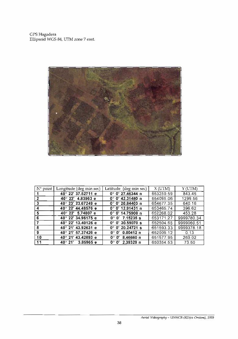
GPS HagaderaEllipsoid WGS 84, UTM zone 7 east.
N° point Longitude (deg min sec) Latitude (deg min sec) X(UTM) y (UTM)1 40° 22' 37.52711 e 0° 0' 27.46344 n 653250.59 843.452 40° 23' 4.83963 e 0° 0' 42.31480 n 654095.06 1299.563 40° 23' 23.67249 e 0° 0' 20.84403 n 654677.35 640.164 40° 22' 44.48576 e 0° 0' 12.91431 n 653465.74 396.625 40° 22' 5.74807 e 0° 0' 14.75908 n 652268.02 453.286 40° 22' 34.96175 e 0° 0' 7.15235 s 653171.27 9999780.347 40° 22' 13.40126 e 0° 0' 30.59070 s 652504.65 9999060.518 40° 21' 43.92631 e 0° 0' 20.24721 s 651593.33 9999378.189 40° 21' 57.37426 e 0° 0' 0.00412 n 652009.12 0.1310 40° 21' 43.42893 e 0° O' 8.46660 n 651577.95 260.0211 40° 21' 3.85965 e 0° 0' 2.39329 n 650354.53 73.50
Aerial Videography - UNHCR-IRD(ex-Orstom), 1999
38

GPS DagahaleyEllipsoid WGS 84, UTM zone 7 east
N° point LonRitude (deg min sec) Latitude (deg min sec) X (UTM) Y (UTM)1 40° 17' 53.28873 0° 11' 21.13002 644461.67 20918.002 40° 17' 39.30619 0° 11' 12.79209 644029.38 20661.903 40° 17' 21.02936 0° 10' 51.44641 643464.36 20006.324 40° 17' 6.83882 0° 11' 3.11361 643025.60 20364.605 40° 16' 38.78768 0° 11' 25.77771 642158.28 21060.566 40° 16' 58.40260 0° 11' 41.12036 642764.68 21531.797 40° 17' 7.24282 0° 12' 9.97049 643037.93 22417.818 40° 17' 29.64553 0° 11' 52.66090 643730.61 21886.289 40° 17' 25.47761 0° 11' 31.71123 643601.79 21242.8910 40° 17' 53.69498 0° 11' 37.61586 644474.19 21424.2911 40° 17' 55.45202 0° 11' 23.22025 644528.55 20982.2012 40° 18' 1.96056 0° 11' 28.33349 644729.76 21139.24
Amal Videography - UNHCR-IRD(ex-Orstom), 1999
39
Chapter 6
Capture of fixed images
The.principle of the digital videography
The numerical videography makes it possible to obtain 50 (pal/Secam) or 60 (NTSC) images a second,the video signal corresponding to each image being coded in numerical form. Numerical coding makes itpossible to preserve intact the quality of the video signal, contrary to analogical coding. It also makes itpossible to recover in numerical form each image without loss of quality.
The images recorded by a video camera are called "frames", for when one visualises a video on a cathode ray tube, one sequentially displays the frames by interlacing them : first frame on the even Unes, secondframe on the odd Unes, third frame on the even Unes, etc. One thus obtains the illusion of 25 (pal/Secam)or 30 (NTSC) images a second, with a vertical resolution twice higher than the resolution of each frame,while ensuring a perfect fluidity of an image to another when the movement is important: the video privileges the quality of the movement to the quality of the image.
The miniDVfonnat
The majority of the general public using numerical video camera uses the miniDV format. InPal/Secam, it corresponds to a size of 768*550 pixels (720*560 in NfTSC) for each screen. The cassettes available last one hour or thirty-minute.
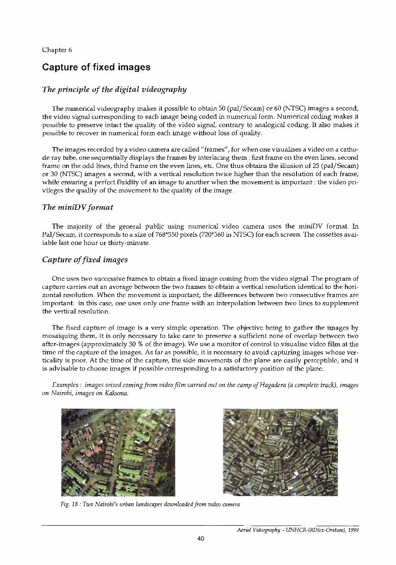
Capture offixed images
One uses two successive frames to obtain a fixed image coming from the video signal. The program ofcapture carries out an average between the two frames to obtain a vertical resolution identical to the horizontal resolution. When the movement is important, the differences between two consecutive frames areimportant: in this case, one uses only one frame with an interpolation between two Unes to supplementthe vertical resolution.
The fixed capture of image is a very simple operation. The objective being to gather the images bymosaïquing them, it is only necessary to take care to preserve a sufficient zone of overlap between twoafter-images (approximately 30 % of the image). We use a monitor of control to visualise video film at thetime of the capture of the images. As far as possible, it is necessary to avoid capturing images whose verticality is poor. At the time of the capture, the side movements of the plane are easily perceptible, and itis advisable to choose images if possible corresponding to a satisfactory position of the plane.
Examples: images seized coming from video film carried out on the camp ofHagadera (a complete track), imageson Nairobi, images on Kakuma.
Fig. 18: Two Nairobi's urban landscapes downloaded from video camera
Aeriil/ Videography - UNHCR-IRD(ex-Orstom), 1999
40

Fig. 19: Images dawnloaded from Ktùcuma's survey
Aerial Videography - UNHCR-IRD(ex-Orstom), 1999
41

Fig. 20 : Images downloaded from Hagadera's suruey (central track)
42
Aerial Videogrlrphy - UNHCR-IRD(ex-Orstom), 1999

Chapter 7
Adjustment, correction and mosaic
The images captured from videotaping do not have geo-reference : they have sorne global or local dis-tortions and therefore must be corrected in order to better be conform to the geographical realities and tobe used in a geographical information system. In this chapter, we are going to describe aIl the operations,which are necessary to achieve a geo-referenced image in the overaD area, covered by the aerial video-filming exercise.
Distortions and adjustments
The images captured from videotaping do not correspond to the geographical realities. They have global and local distortions; they are not positioned in the space; they do not correspond to selected geographical projection (UTM, Mercator, Lambert ... ). Many types of distortions happen :
• Distortions due to the passage of rays of light and the optics of the video camera;• Distortions due to the positioning of the video camera: horizontally and altitude;• Distortions due to the area relief;• Mathematical distortions to adjust to a given geographical projection.
Distortions due to the camera optic can be modelled by using a focal adjustment instrument.Nevertheless, these distortions depend on the focal distance. The optic camera we have been using presents only very few distortions, even when the focal distance is short. Note that for this camera, the shortest focal distance represents an equivalent of 24*36 of about 40 mm which remains a quite long focal inthe realm of aerial photography.
The distortions due to the passage of rays of light cannot be modeIled because they depend upon theweather conditions. Those distortions are meaningless in case of these fIight altitudes.
The most important distortions are due to the positioning of the camera as compared to the vertical.These distortions are of two types: horizontality and altitude. The video camera foIlows the movementsof the plane since it is mounted on its stand. Such a mounting enables only to approximately adjust theazimuth. Assuming that the filmed area is fiat, the rectangular image obtained at the moment of filmingcorresponds indeed to a trapezium on the growld. TIùs is a polynomial distortion whose degree is 1 andthe coefficients may be obtained by knowing the equation of the plan of the camera. As the position of thecamera is not known at the time the filming is done, the equation of the plan as related to the plan of theprojection can be calculated thanks to four landmarks. The polynomial distortion also corrects the differences between the actual altitude of the camera and the theoretical altitude of the fIight plan.
The distortion due to the relief should, if possible, be taken into account. In fact, the previous distortion does not take into account the altitude of the points in the image: the points are projected in the planas if they were ail at the zero altitude, whereas the projection must foIlow the vertical but not a ray of lightfrom an altitude assumed to be the point. In order to take into account that distortion, it is necessary toknow the relief in aD points and therefore have a digital model of the field.
The image fiImed by the camera corresponds to the curvilinear surface of the ground, whereas theresuIt should be given in a plan by using a geographical projection from positions expressed on the ellipsoid of reference. That mathematical distortion is known, that is the geographical projection.
The correction of the image will therefore attempt to remove aD those distortions in order to have angeo-referenced image in a plan of projection and corresponding as better is possible to the geographic reality.
As altitude is in general not known, we will use to simplify a polynomial of degree one deformation,global or local, to simulate the projective deformation.
Amal Videography - UNHCR-IRD(ex-Orstom), 1999
43

Re-sampling
Correction is done together with re-sampling : the pixels in the original images do not necessarily havethe same size as the pixels in the final stage images. actually, the pixels never have the same size since theyare altered by a series of correction exercises. Therefore the process goes the other way round: the size andthe position of the pixel in the final image is determined, then the calculation of its (radiometric) value isdone by trying to find the corresponding pixel(s) in the original image, after aU the reversed distortions.Therefore, the re-sampling exercise consists in choosing the size of the pixel in the final image and in choosing the function in calculating the value of the radiometry from the corresponding pixel in the originalimage (very close to bilinear function, bi-cubic function, etc). This exercise is essential : it enables to passfrom an estimated value to a fixed value regarding the pixel in a given projection.
In fact, the resolution of an image corresponds to the size of its pixels and to the objects which can bedefined and noticed in the image together with that pixel size (for example, with a one meter pixel, onecan notice cars). The accuracy of an image corresponds to the absolute accuracy of localisation. Even if theimage does not have any geo-reference, it has an estimated resolution, which is also evaluated most of thetime in meter per size of a pixel.
The adjusting exercise
The adjusting methods are numerous : they essentially depend upon the type of distortion where theimage to be straightened is related, to the possibilities of the filming of the landmark points, to the availability of a digital model in the field.
One can use:
• a translation: in this case, the image is already in conformity with the geographical projection, thesize of the pixel is known, the translation is used only to locate the image but does not carry out any transformation on the pixels. Only one point of reference is necessary to carry out a translation.
• a translation and a rotation: it is the simplest transformation, to use if the image is geographicallycorrect but must undergo a translation and a rotation to be in conformity with the reference mark of projection. The distances in the image are not modified. Two landmarks are necessary to carry out this transformation.
• a similarity : it is a translation and a rotation foUowed by a homothety (put on the scale). The similarity is to be used when, to be put in conformity with a geographical projection, the image must undergo a translation, a rotation, then a scaling. The scaling is identical on the whole of the image, the deformation is identical whatever the direction (it is a isometry). Two landmarks are necessary for this transformation.
• a polynomial deformation of degree 1 : this deformation is identical to the similarity, except that thescaling is not identical some is the direction. Three landmarks are necessary to carry out this transformation.
• a projective deformation (or homography) : it is a classical projection of a plan on a plan starting froma point. It is the natural deformation obtained on a photograph, when the ground photographed corresponds to a plan. This transformation must be combined with a deformation taking into account altitude,if not the scale obtained is not correct. Four points are necessary to fix the coefficients of titis transformation, which amounts gauging the position of the camera compared to the plan of projection.
• A deformation by triangulation: this deformation combines a first global transformation (rotation,similarity, polynomial of degree 1, homography), with a local deformation of degree 1 in each triangleresulting from a triangulation starting from the seized points of land-marks. This transformation is mosteffective when one does not have a digital model of ground making it possible to know altitude in eachpoint. Indeed it established a model of polynomial deformation of degree in each triangle. The deformation corresponds to a space division in plane facets, and if network of points of landmark is dense and
Amal Videography - UNHCR-IRD(ex-Orstom), 1999
44

Fig. 21 : Geometrical images correction and mosaic (Hagadera)
45Amal Videography - UNHCR-IRD(ex-Orslom), 1999

homogeneous (and ail the denser that the differences in altitude are large), the rectification makes it possible to directly obtain an image in conformity with selected geographical projection. This type of deformation also makes it possible to ensure a perfect joint between various images: once a rectified image, itis enough to seize points of landmarks between the rectified image and the image to readjust to make coincide the two images. The initial transformation makes it possible to fix the image coarsely to be rectified :it must correspond as weIl as possible to the type of deformation to which this image is subjected. Thepolynomial rectification of degree 1 or by homography (if one knows the altitude of the points of landmarks) is often most adequate.
The deformations of the images taken by videography come primarily from the (1ack of) horizontalityof the plane and the relief. The optical deformations are negligible, just like the deformations due to thetransport of the luminous rays. The best rectification is thus carried out thanks to a polynomial transformation of degree 1, or a projective transformation (if one knows the altitude of the points of land-marks),followed by a transformation by triangulation. If the network of point of landmarks is sufficiently dense,ail the deformations are corrected and the rectified image is geographicaily correct (the local scales areexact). The principal difficulty thus lies in the availability of this network of points of land-marks, pointswhich can be obtained either starting from an existing cartography, or starting from images satellite (butwith a less precision, and provided that the satellite image is itseIf correctly rectified and geo-referenced),or starting from points GPS taken directly on the ground.
Introduction of the mosaic in a GIS
Once rectified, an image can he integrated in a unit so as to constitu te a orthophotoplan. This operation is called " mosaïquing ". The mosaic thus made up is geo-referenced and is managed and used in ageograplùcal information system. The many images coming from the videography disappear to leaveroom to only one image directly managed by the information system. The geographical information system SAVANNA was used for aIl the operations of rectification and mosaïquing presented in this document.
Fig. 22 : Three rejugee camps mosaicsoverlapped on the Spot panchromaticimage
Aerial Videography - UNHCR-IRD(ex-Orstom), 1999
46

Kakuma camp
47
Amal Videography - UNHCR-IRD(ex-Orstom), 1999

Fig. 23 : Kakuma camp mosaic de/ails (resolution 1,2 m)
Aerial Videography - UNHCR-IRD(ex-Orstom), 1999
48

Dagahaley camp
Fig. 24 : Dagahaley camp mosaic de/ails (reso/ution = 1 m)
49
Amal Videography - UNHCR-IRD(ex-Orstom), 1999

Hagadera camp
Fig. 25 : Hagadera camp mosaic (resolution = 1 m)
Aerial Videography - UNHCR-IRD(ex-Orstom), 1999
50

Ifo camp
Fig. 26 : 1fo camp mosaic details (resolution = 1 m)
51Amal Videography - UNHCR-fRD(er-Orstom), 1999

Chapter 8
Using mosaic in a geographical information system
Geographical Information Systems background
The geographical information systems are data management systems with two or three dimensions(x,y,z). They make it possible to manage and process the localisation in the space of the preserved objects,which model reality. These objects are zones, lines, points, or pixels of images. Each object is described by" attributes " : the objects described by the same attributes are gathered in collections (or layers). Thesecollections are connected with the relations of a classical relational data base management system.
AlI the geographical data present in a GIS can he compared the ones with the others by using their localisation in space, to analyse and process them or chart them. It is thus very important to manage this localisation in space weIl, and to control all the aspects of them : precision, validity, space of reference, etc. Ifthe recovery of the video images is weil carried out, the mosaic answers these criteria and can he used ina GIS and can he put in relation with other localised objects.
Mosaics management
Among the objects managed by a GIS, the mosaics of images often hoId a place separately. In theSAVANNA system, these objects are integrated in the base of data as weIl as the other types of geographical data. The mosaics can thus be used without particular effort. Once integrated in the base of data,the system takes care with all the management of these mosaics, which often represent great volumes ofinformation.
Digitization on the mosaic
Once integrated in the data base, a mosaic can be used as reference to seize other objects : one candirectly digitize these objects on a screen of computer by using the mosaic like a reference.
Aerial Videography - UNHCR-TRD(ex-Orslom), 1999
52
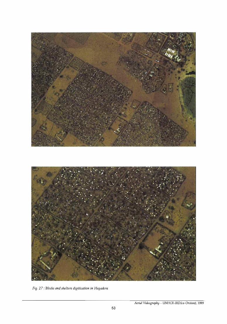
- "... ·...
;., ., \ .'
1
""
:t .
. • , - -,
•.
-,, ,"
, -
,. .-
.' .
. · ,.
,•
, ..........' ..
'.,
.,- ....
.. •
~ , ,.
,
' , ."
. , . , ,,
~~ ...
~ .;
..
,
'!.'
.. •
,
.. "
j
"
.'
,
..
1
~
, ,
,d
..., .p.
.
.
,.1
..~
..
'.
~
..
"
. C
.'.
. .-
..
;
..:
~
.,.
..
,."
# "'1
.,
:
..., •
~
.'
. "
• ·~
--. ·"
.... ....
. <{-.- .j ·
", " '-.
•
. J~
. ,1
.- ,
.. ..
"
.:..~
-.'
.' ~
.
. ,
.
.-~ ~.
•"
t •
. .. , •1
. ~.
....
.. 1
. ..'
Fig. 27 : Blacks and shelters digitizatian in Hagadera
Aeriill Videograplry - UNHCR-IRD(ex-Orstom), 1999
53

Bibliography
Generalities
Sciences géométriques et télédétection, L. Lliboutry, Masson, 1992Géométrie projective, J.c. Sidler, Intereditions, 1993Vision par Ordinateur, Outils fondamentaux, Radu Horaud, Olivier Monga, Hermes, 1995
GPS
Le Grs et ses applications, Leica, 1995Magellan Promark X-CM, Operation ManualLes principes du Grs, Hermes
GIS
GIS, a Computer Perspective, M.F. WorBoys, Taylor&Francis, 1995SGBD Géographiques, Spécificités, M. Scholl and ail, Thomson Publishing, 1996Savamer, Manuel d'utilisation, Marc Souris, 1999Savane, Manuel d'utilisation, Marc Souris, 1998
Aerial Videography - UNHCR-IRD(ex-Orstam), 1999
54