volumetric light-shaping polymer-dispersed liquid crystal
TRANSCRIPT

Volumetric light-shaping polymer-dispersed liquid crystal films for mini-LEDbacklightsZiqian He, Kun Yin, En-Lin Hsiang and Shin-Tson Wu
College of Optics and Photonics, University of Central Florida, Orlando, FL, USA
ABSTRACTVolumetric light-shaping polymer-dispersed liquid crystal (PDLC) films for mini-LED backlit liquidcrystal displays (LCDs) are proposed and experimentally demonstrated. With proper materialengineering and good vertical alignment of liquid crystals, passive PDLC films with angle-selective scattering properties can be achieved. Such films only respond to angles rather thanspatial locations. By directly adhering the PDLC films onto a LED, angular intensity distribution oflight can be tailored from Lambertian-like to batwing-like. Further simulation shows that byengineering the angular distribution, a fewer number of LEDs or equivalently a shorter light-spreading distance should be required to maintain good uniformity. Such a PDLC film would findwidespread applications in emerging mini-LED backlit LCDs and shed light on designing otherlight-shaping films in the future.
ARTICLE HISTORYReceived 9 December 2019Accepted 24 February 2020
KEYWORDSPolymer-dispersed liquidcrystals; volumetric diffusers;angle-dependent scattering;mini-LED backlights
1. Introduction
To fulfil the urgent need on high dynamic range, mini-LED (light emitting diode) backlit liquid crystal displays(LCDs) are emerging [1,2]. With locally dimmable LEDzones, a contrast ratio higher than 106:1 and visualperformance similar to self-emissive displays such asorganic LEDs (OLEDs) can be achieved [3,4].However, the use of thousands or more of mini LEDswill increase the cost substantially because the masstransfer yield and defect mapping and repair speed ofmini-LED chips still need improvement. Moreover, thedirect backlight is still too thick for smartphones [5].Increasing the number of LEDs can effectively reducethe backlight thickness but with an even higher cost.Another method is to tailor the angular distribution oflight so that the light emitted from mini-LEDs can
spread out faster in a shorter propagation distance,where sophisticated surface microstructures are usuallyneeded [6,7].
In this paper, we demonstrate a new volumetric light-shaping polymer-dispersed liquid crystal (PDLC) film formini-LED backlit LCDs. By choosing proper refractiveindices of liquid crystals (LC) and polymer, and providingsufficiently strong anchoring to the LC droplets along thevertical direction, a passive PDLC film with angle-selective scattering properties can be realised. Sucha PDLC film can effectively scatter the normally incidentlight and increase the transmittance of light at a range ofoblique incident angles, and they only respond to light atdifferent angles but not at different spatial locations.Adhering such films directly onto LEDs, the angularintensity distribution of light can be tailored from
CONTACT Shin-Tson Wu [email protected]
LIQUID CRYSTALS2020, VOL. 47, NO. 10, 1458–1463https://doi.org/10.1080/02678292.2020.1735546
© 2020 Informa UK Limited, trading as Taylor & Francis Group

Lambertian-like to batwing-like. Further simulationshows that by engineering the angular distribution oflight, a much fewer number of LEDs is required to main-tain high uniformity at a fixed propagating distance.
2. Working principles
In a traditional scattering-type PDLC, the LC moleculesform micron-sized droplets dispersed in the polymermatrix by phase separation [8]. Within each droplet,the LCs are aligned in a certain direction to minimisethe free energy. However, the aligned directions arerandom among different droplets, which will causelight scattering macroscopically. If the ordinary refrac-tive index of LCs (no) matches the refractive index of thepolymer (np), the PDLC cell can be switched transparentwhen a sufficient voltage is applied to align all thedroplets along the vertical direction (assuming the hostLC has a positive dielectric anisotropy) [9–11]. Selectivescattering will be observed in such a PDLC in the vol-tage-on state, where the normal incidence shows hightransmittance and the scattering becomes stronger asthe incident angle increases [12,13]. This selective-scattering property can be utilised to outcouple thewaveguiding mode in OLEDs. Previously, somewhataligned passive PDLC films were achieved by curingthe PDLC precursors with a reactive mesogen andunder a high voltage [14].
Aligning LC droplets in vertical direction is highlydesirable in our case. However, the refractive index ofthe polymer is selected to be different from the ordinaryrefractive index of LCs (np ≠ no) but matches the effec-tive refractive index of the employed LC at some obliqueincident angle α (np = neff), where neff can be calculatedusing no, ne (the extraordinary refractive index of theLC), and α as [15]:
neff ¼ noneffiffiffiffiffiffiffiffiffiffiffiffiffiffiffiffiffiffiffiffiffiffiffiffiffiffiffiffiffiffiffiffiffiffiffiffin2ecos
2αþ n2osin2α
q (1)
As shown in Figure 1, due to the refractive index mis-match, the normally incident light (along z direction) isscattered independent of polarisations. At an obliqueincidence, the film is polarisation dependent. Ideally, thep-polarised light sees np of the polymer and neff of the LCdroplets (Figure 1(a)). As the incident angle increases, therefractive index mismatch and thus scattering decreasesfirst, reaches the minimum value at α, and then increasesagain. On the other hand, the s-polarised light sees np ofthe polymer and no of the LC droplets no matter at whatincident angle (Figure 1(b)). Therefore, it is even morescattered at oblique incidence due to the increased opticalpath length inside the polymer matrix. This principleapplies to not only the xz plane but also the yz plane. Ifthe alignment of LC droplets is not good enough, the lossof angular selectivity from s-polarised light will offset thegain from p-polarised light. Consequently, realising good
Figure 1. (Colour online) Schematic illustration of the working principles when (a) p-polarised and (b) s-polarised light rays areincident on the proposed PDLC film.
LIQUID CRYSTALS 1459
vertical alignment of LC droplets for such passive films iscrucial.
It is worth mentioning that 3M has experimentallydemonstrated a different angle-dependent birefringentdiffuser using polymer beads-in-polymer systems wherethe polymer beads are isotropic, and the polymer matrixis anisotropic [16]. By stretching the composites at anelevated temperature, the optical axis of the polymermatrix can be aligned along the stretching direction(e.g. x-axis) while the polymer beads remain isotropic.This composite film can achieve angle-selective scatter-ing, but only in the xz plane. Moreover, the angularselectivity realised in the experiment is somewhatweak. Therefore, it still needs improvement in order tobe employed in the mini-LED backlight system.
3. Experimental and simulation results
Our initial attempt is to fabricate a thick (~50 μm) filmsimilar to that reported in [14]. After sweeping thematerial composition (weight ratio of LCs, reactivemesogens and prepolymers) and the fabrication condi-tion (applied electric field, UV light irradiance and cur-ing time duration), we successfully fabricated partiallyaligned PDLC samples. Specifically, a 50-μm LC cellwithout surface alignment was filled with a precursormixture containing 49.92% ZLI 1844 (Merck; birefrin-gence Δn = 0.18), 2.97% RM 257 (reactive mesogen) and47.11% NOA 60 (prepolymer with np = 1.56). In thepresence of a 4 V/μm electric field, the cell was exposedunder UV light with an irradiance of 5 mW/cm2 for 40min. To characterise its selective scattering properties,the passive PDLC was fixed on a rotation stage and set tothe centre of a glass cylindrical container filled with anindex matching oil. The incident light (from a 450-nmlaser diode) was perpendicular to the PDLC at the initialstate, and the incident angle could then be adjusted byrotating the PDLC. The transmittance is normalised tothe case where the PDLC is absent and the collection
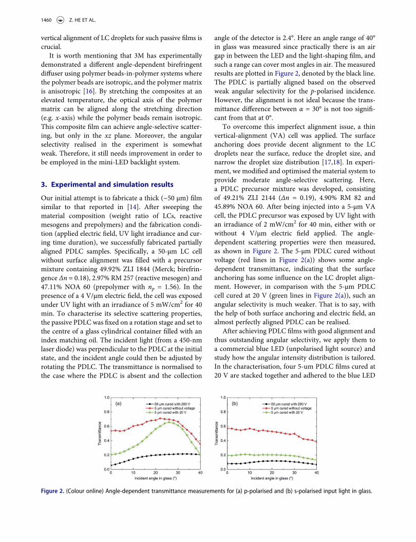
angle of the detector is 2.4°. Here an angle range of 40°in glass was measured since practically there is an airgap in between the LED and the light-shaping film, andsuch a range can cover most angles in air. The measuredresults are plotted in Figure 2, denoted by the black line.The PDLC is partially aligned based on the observedweak angular selectivity for the p-polarised incidence.However, the alignment is not ideal because the trans-mittance difference between α = 30° is not too signifi-cant from that at 0°.
To overcome this imperfect alignment issue, a thinvertical-alignment (VA) cell was applied. The surfaceanchoring does provide decent alignment to the LCdroplets near the surface, reduce the droplet size, andnarrow the droplet size distribution [17,18]. In experi-ment, we modified and optimised the material system toprovide moderate angle-selective scattering. Here,a PDLC precursor mixture was developed, consistingof 49.21% ZLI 2144 (Δn = 0.19), 4.90% RM 82 and45.89% NOA 60. After being injected into a 5-μm VAcell, the PDLC precursor was exposed by UV light withan irradiance of 2 mW/cm2 for 40 min, either with orwithout 4 V/μm electric field applied. The angle-dependent scattering properties were then measured,as shown in Figure 2. The 5-μm PDLC cured withoutvoltage (red lines in Figure 2(a)) shows some angle-dependent transmittance, indicating that the surfaceanchoring has some influence on the LC droplet align-ment. However, in comparison with the 5-μm PDLCcell cured at 20 V (green lines in Figure 2(a)), such anangular selectivity is much weaker. That is to say, withthe help of both surface anchoring and electric field, analmost perfectly aligned PDLC can be realised.
After achieving PDLC films with good alignment andthus outstanding angular selectivity, we apply them toa commercial blue LED (unpolarised light source) andstudy how the angular intensity distribution is tailored.In the characterisation, four 5-um PDLC films cured at20 V are stacked together and adhered to the blue LED
Figure 2. (Colour online) Angle-dependent transmittance measurements for (a) p-polarised and (b) s-polarised input light in glass.
1460 Z. HE ET AL.

directly. Here, four films are utilised to increase thecontrast of angle-selective scattering. As Figure 3shows, the angular intensity distribution of the LEDwithout PDLC films is already quite broad with a peakat the normal view. After the PDLC films are applied,the angular intensity distribution of the LED becomesbatwing-like, with a peak at about 40° in air and theintensity at normal view is about 77% of that at 40°. Formini-LED backlights, a batwing-like angular distribu-tion can spread the light out much faster thana Lambertian-like angular distribution. Therefore, theintroduction of the light-shaping films into the back-light system should effectively decrease the backlightthickness or/and reduce the number of mini-LEDs.
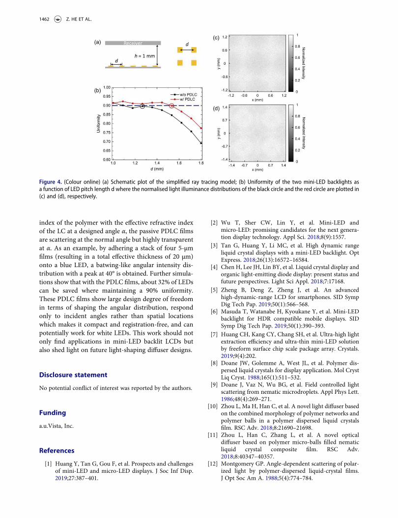
To show how this angular distribution change influ-ences the mini-LED backlight system, a simplified ray-tracing simulation model in LightTools is established.As demonstrated in Figure 4(a), mini-LEDs with a sizeof 200 × 200 μm2 are arranged in a square lattice witha lattice constant (pitch) of d, and a receiver is placed1 mm away from the mini-LED backplane. By assigningthe angular intensity distributions illustrated in Figure 3to the LEDs, light uniformity at the receiver plane can beobtained, which is calculated by:
uniformity ¼ 1� Imax � Imin
Imax þ Imin(2)
where Imax and Imin denote the maximum and mini-mum illuminances at the receiver plane, respectively.The simulated uniformity as a function of d for thetwo angular intensity distributions is depicted inFigure 4(b). If we set a target uniformity of 90%, thenthe largest pitches for the LED without PDLC, and theLED with PDLC are about 1.26 mm and 1.53 mm,respectively. These two cases are circled in Figure 4(b),and the corresponding normalised illuminance distribu-tions are plotted in Figure 4(c) (without PDLC) andFigure 4(d) (with PDLC). The illuminance distributionplots have a dimension of 2d × 2d, which encloses fourmini-LEDs. By utilising the PDLC films, about 32%
(= 1-(1.26/1.53)2) of the mini-LEDs can be saved toachieve the same uniformity.
It should be pointed out that our simulation model issimplified for proving concept. In real cases, brightnessenhancement films (BEFs) and/or other films will still berequired to narrow the angular distribution of light anddepolarise the light before entering the LCmodule so thatthe light intensity distribution after passing through thepolariser of the LCmodule remains uniform. Back reflec-tors are also useful for recycling the reflected light fromPDLC [19]. Nevertheless, since the effective thickness ofthe PDLC films is only about 20 μm, applying thesePDLC films to the existing mini-LED backlight systemhelps to reduce the number of LEDs and/or the backlightthickness. Another aspect is that for a white backlight,a separate colour-conversion layer is indispensable if onlyblue LEDs are employed. But fortunately, the PDLC filmsare intrinsically broadband. Consequently, they arehighly promising to be directly applied to white LEDs.
The optical properties of the PDLC films can also betailored according to different requirements. For exam-ple, the angle of maximum transmittance can be tunedby engineering the refractive indices of the employed LCand polymer as long as np matches neff at α. The scatter-ing strength can also be adjusted by controlling theindex mismatch between np and no and/or the totalthickness of the PDLC film. The large variability ensuresthe potential of almost arbitrary tailoring the angulardistribution of LEDs. More importantly, with good spa-tial uniformity, such a PDLC film only responds todifferent angles rather than spatial locations.Therefore, these films can be placed in close vicinity tothe LEDs without registration issue so that the backlightunit can be very compact.
4. Conclusion
In conclusion, volumetric light-shaping PDLC films formini-LED backlit LCDs are proposed and experimen-tally demonstrated. By vertically aligning the LC dro-plets in the polymer matrix and matching the refractive
Figure 3. (Colour online) Measured angular intensity distribution of a commercial LED without (black) and with (red) PDLC films.
LIQUID CRYSTALS 1461
index of the polymer with the effective refractive indexof the LC at a designed angle α, the passive PDLC filmsare scattering at the normal angle but highly transparentat α. As an example, by adhering a stack of four 5-μmfilms (resulting in a total effective thickness of 20 μm)onto a blue LED, a batwing-like angular intensity dis-tribution with a peak at 40° is obtained. Further simula-tions show that with the PDLC films, about 32% of LEDscan be saved where maintaining a 90% uniformity.These PDLC films show large design degree of freedomin terms of shaping the angular distribution, respondonly to incident angles rather than spatial locationswhich makes it compact and registration-free, and canpotentially work for white LEDs. This work should notonly find applications in mini-LED backlit LCDs butalso shed light on future light-shaping diffuser designs.
Disclosure statement
No potential conflict of interest was reported by the authors.
Funding
a.u.Vista, Inc.
References
[1] Huang Y, Tan G, Gou F, et al. Prospects and challengesof mini-LED and micro-LED displays. J Soc Inf Disp.2019;27:387–401.
[2] Wu T, Sher CW, Lin Y, et al. Mini-LED andmicro-LED: promising candidates for the next genera-tion display technology. Appl Sci. 2018;8(9):1557.
[3] Tan G, Huang Y, Li MC, et al. High dynamic rangeliquid crystal displays with a mini-LED backlight. OptExpress. 2018;26(13):16572–16584.
[4] Chen H, Lee JH, Lin BY, et al. Liquid crystal display andorganic light-emitting diode display: present status andfuture perspectives. Light Sci Appl. 2018;7:17168.
[5] Zheng B, Deng Z, Zheng J, et al. An advancedhigh-dynamic-range LCD for smartphones. SID SympDig Tech Pap. 2019;50(1):566–568.
[6] Masuda T, Watanabe H, Kyoukane Y, et al. Mini-LEDbacklight for HDR compatible mobile displays. SIDSymp Dig Tech Pap. 2019;50(1):390–393.
[7] Huang CH, Kang CY, Chang SH, et al. Ultra-high lightextraction efficiency and ultra-thin mini-LED solutionby freeform surface chip scale package array. Crystals.2019;9(4):202.
[8] Doane JW, Golemme A, West JL, et al. Polymer dis-persed liquid crystals for display application. Mol CrystLiq Cryst. 1988;165(1):511–532.
[9] Doane J, Vaz N, Wu BG, et al. Field controlled lightscattering from nematic microdroplets. Appl Phys Lett.1986;48(4):269–271.
[10] Zhou L, Ma H, Han C, et al. A novel light diffuser basedon the combined morphology of polymer networks andpolymer balls in a polymer dispersed liquid crystalsfilm. RSC Adv. 2018;8:21690–21698.
[11] Zhou L, Han C, Zhang L, et al. A novel opticaldiffuser based on polymer micro-balls filled nematicliquid crystal composite film. RSC Adv.2018;8:40347–40357.
[12] Montgomery GP. Angle-dependent scattering of polar-ized light by polymer-dispersed liquid-crystal films.J Opt Soc Am A. 1988;5(4):774–784.
Figure 4. (Colour online) (a) Schematic plot of the simplified ray tracing model; (b) Uniformity of the two mini-LED backlights asa function of LED pitch length d where the normalised light illuminance distributions of the black circle and the red circle are plotted in(c) and (d), respectively.
1462 Z. HE ET AL.

[13] Vaz NA, Smith GW,Montgomery GP. A light control filmcomposed of liquid crystal droplets dispersed in a UV-curable polymer. Mol Cryst Liq Cryst. 1987;146(1):1–15.
[14] Jiang J, McGrawG, Ma R, et al. Selective scattering polymerdispersed liquid crystalfilm for light enhancement of organiclight emitting diode. Opt Express. 2017;25(4):3327–3335.
[15] Yeh P, Gu C. Optics of liquid crystal displays.New York: John Wiley & Sons; 1999.
[16] O’Neill MB, Stover CA, Weber MF, inventor; 3M inno-vative properties Co., assignee. Direct-lit backlight withangle-dependent birefringent diffuser. United Statespatent US8,007,118. 2011 Aug 30.
[17] Lin YH, Ren H, Wu ST. High contrast polymer-dispersed liquid crystal in a 90° twisted cell. Appl PhysLett. 2004;84(20):4083–4085.
[18] Lin YH, Ren HW, Wu YH, et al. Pinning effect onthe phase separation dynamics of thinpolymer-dispersed liquid crystals. Opt Express.2005;13(2):468–474.
[19] Kim B, Kim J, OhmWS, et al. Eliminating hotspots in amulti-chip LED array direct backlight system with opti-mal patterned reflectors for uniform illuminance andminimal system thickness. Opt Express. 2010;18(6):8595–8604.
LIQUID CRYSTALS 1463