voluntary safety recall campaign 2002 – 2006 · pdf filemake sure to use new module...
TRANSCRIPT
1/22
Reference: Date:
NTB17-055 July 19, 2017
VOLUNTARY SAFETY RECALL CAMPAIGN 2002 – 2006 SENTRA; FRONT PASSENGER AIR BAG INFLATOR
CAMPAIGN ID #: PM683
NHTSA #: 15V-287
APPLIED VEHICLES: 2002 – 2006 Sentra (B15)
Check Service COMM to confirm campaign eligibility.
INTRODUCTION
Nissan is conducting this voluntary safety recall campaign on certain specific 2002 – 2006 Sentra vehicles to replace the front passenger air bag inflator. This service will be performed at no charge to the customer for parts or labor.
Takata has issued return packaging, shipping labels, documents, and directions that must be used and followed in order to properly carry out this campaign. Takata’s documentation is attached and is part of this bulletin. IDENTIFICATION NUMBER
Nissan has assigned identification number PM683 to this campaign. This number must appear on all communication and documentation of any nature dealing with this campaign. DEALER RESPONSIBILITY
It is the dealer’s responsibility to check Service COMM for the campaign status on each vehicle falling within the range of this voluntary safety recall campaign which for any reason enters the service department. This includes vehicles purchased from private parties or presented by transient (tourist) owners and vehicles in a dealer’s inventory. Federal law requires that new vehicles in dealer inventory which are the subject of a safety recall must be corrected prior to sale. Failure to do so can result in civil penalties by the National Highway Traffic Safety Administration. While federal law applies only to new vehicles, Nissan strongly encourages dealers to correct any used vehicles in their inventory before they are retailed.
Nissan Bulletins are intended for use by qualified technicians, not 'do-it-yourselfers'. Qualified technicians are properly trained individuals who have the equipment, tools, safety instruction, and know-how to do a job properly and safely. NOTE: If you believe that a described condition may apply to a particular vehicle, DO NOT assume that it does. See your Nissan dealer to determine if this applies to your vehicle.

2/22 NTB17-055
REQUIRED SPECIAL TOOL (J-51315)
Figure A
Air bag module support
Support bracket
Bolts and nuts for attachment

3/22 NTB17-055
REQUIRED SPECIAL TOOLS continued Quick Scan Tool (J-52352)
Each retailer has been shipped one Quick Scan Tool (J-52352).
Additional tools can be obtained from Tech•Mate at 1-800-662-2001.
Figure B

4/22 NTB17-055
SERVICE PROCEDURE
IMPORTANT: Follow all cautions, warnings, and notes in the Electronic Service Manual (ESM) when working on or near a Supplemental Restraint System (SRS), such as an air bag.
CAUTION: Handle interior trim carefully to avoid damage. Work with clean hands and clean tools to avoid dirt and stains. Use protective covers as needed.
1. Write down the radio settings.
Presets 1 2 3 4 5 6
AM
FM 1
FM 2
SAT 1
SAT 2
Bass Treble Balance Fade Speed Sen. Vol.
2. Turn the ignition OFF.
3. Disconnect both battery cables, negative cable first.
4. Wait at least 3 minutes.
5. Register the new inflator serial number as follows.
The new inflator is listed in the Parts Information.
Figure 1
a. Attach the quick scan tool (J-52352) to your CONSULT PC USB port.

5/22 NTB17-055
b. On the left side of the ASIST main menu, select Tech Support Info, then Inventory Vehicle Actions.
Figure 2
c. Select CLICK HERE (Air Bag to VIN Registration).
Figure 3
Tech Support Info
Inventory Vehicle Actions
Select CLICK HERE

6/22 NTB17-055
Figure 4
VIN will automatically populate (see Figure 5).
If needed, VIN can be entered manually.
Figure 5
d. Use the quick scan tool to scan the bar code (VIN) on the B-pillar label.
Wipe any dirt/debris from bar code before scanning.
NOTE:
Some labels may not scan quickly.
Hold the scan tool approximately 6 inches away from the label.
Hold the trigger down until the
label is read (this may take several seconds).
Step f; see next page. (Select submit after both fields are populated).

7/22 NTB17-055
Figure 6
f. Select Submit on the ASIST screen (see Figure 5 on the previous page).
6. Remove the passenger air bag module (module) from the vehicle.
Refer to the RS section in the appropriate Service Manual for module removal.
IMPORTANT: For Sentra, there is an inspection that needs to be performed during the module removal. See page 9.
7. Set the module in a clean working area.
NOTE: Do not set the module with cover facing down.
e. Use the quick scan tool to scan the bar code (serial number) on the new inflator shipping box.
The serial number will automatically populate (see Figure5 on previous page).
NOTE: If needed, the serial number can be entered manually.
Serial number
Shipping box
xxxxxxxxxxxxx

8/22 NTB17-055
8. Securely mount the air bag module support (support) in a vice (see Figure 7).
Figure 7
WARNING: Work from behind and to the sides of the support.
9. Replace the module inflator:
Sentra; page 10
10. Reinstall the module into the vehicle in reverse order of removal.
Make sure to use new module mounting bolts included with the new inflator.
11. Connect both battery cables – positive cable first. 12. Reset the clock and the radio settings. 13. Turn the ignition ON and observe the air bag warning light:
Light should illuminate for 7 seconds and then go out.
NOTE: If the Air Bag Warning light does not operate as described above there may be an issue not covered by this campaign. Refer to ASIST and the appropriate Service Manual for additional diagnostic and repair information.
14. Return the removed (old / non-deployed) inflator in the box that the new inflator came
in.
Follow the return instructions provided by Takata.
Return instructions provided by Takata are attached to this bulletin on page 22.
Air bag module support (J-51315)

9/22 NTB17-055
SENTRA Inflator Inspection INSPECTION: During module removal, inspect the inflator to confirm it needs to be replaced. 1. When the glove box is removed, look up into the dash (see Figure SA) and locate the right
side of the module inflator. If the inflator has a nut on the end, do not replace.
Reassemble the vehicle and submit a claim for “inspect air bag inflator”. If the inflator does not have a nut on the end, continue with inflator replacement.
Figure SA
Replace Inflators with no nut require replacement.
DO NOT Replace If there is a nut on the end of the inflator, do not replace.
Lo
ok
in h
ere

10/22 NTB17-055
Inflator Removal
WARNING: Wear safety glasses while performing inflator replacement.
Figure S1
Figure S2
1. Set the module on a clean working area. 2. Disconnect the harness clip from the
module frame.
3. Attach the support bracket to the module frame.
Use bolts supplied with the air bag
module support. Tighten the bolts holding the support
bracket to the module frame.
Leave the L brackets on each end slightly loose to allow for positioning of the module in the support.
Harness clip
Module frame
L bracket
Support bracket

11/22 NTB17-055
WARNING: Work from behind and to the sides of the support.
Figure S3
Figure S4
4. Mount the module in the support.
Use bolts and nuts supplied with the support.
5. Make sure the module is centered in the support.
NOTE: Centering the module in the support will allow access to the inflator securing nuts through the slots in the support.
6. Tighten all of the mounting bolts and
nuts that hold the module to the support.
Support
Nuts
12/22 NTB17-055
Figure S5
Figure S6
Figure S7
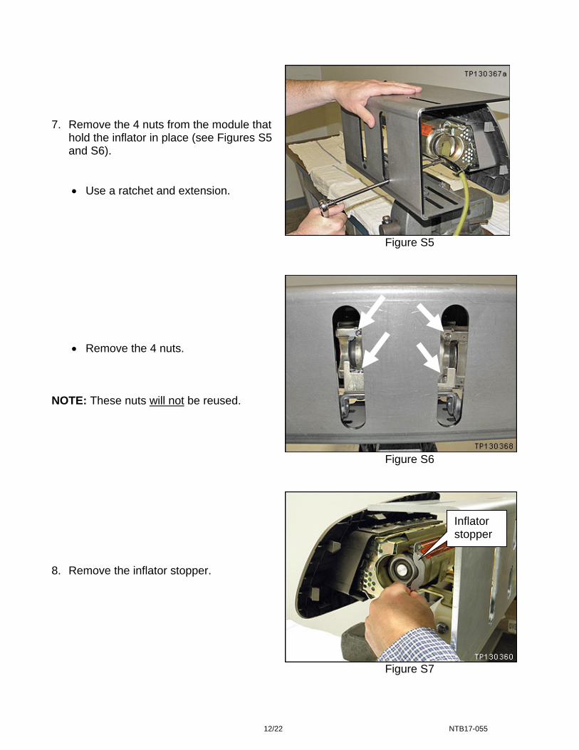
7. Remove the 4 nuts from the module that
hold the inflator in place (see Figures S5 and S6).
Use a ratchet and extension.
Remove the 4 nuts. NOTE: These nuts will not be reused. 8. Remove the inflator stopper.
Inflator stopper
13/22 NTB17-055
Figure S8
Inflator Stopper Bracket Removal
Figure S9
Figure S10
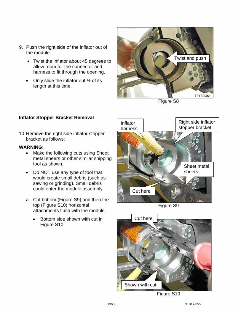
9. Push the right side of the inflator out of the module.
Twist the inflator about 45 degrees to allow room for the connector and harness to fit through the opening.
Only slide the inflator out ½ of its length at this time.
Twist and push
Sheet metal sheers
Right side inflator stopper bracket
Cut here
10. Remove the right side inflator stopper bracket as follows:
WARNING: Make the following cuts using Sheet
metal sheers or other similar snipping tool as shown.
Do NOT use any type of tool that would create small debris (such as sawing or grinding). Small debris could enter the module assembly.
a. Cut bottom (Figure S9) and then the
top (Figure S10) horizontal attachments flush with the module.
Bottom side shown with cut in Figure S10.
Cut here
Shown with cut
Inflator harness

14/22 NTB17-055
Figure S11
Figure S12
Figure S13
11. Slide the detached right side inflator
stopper bracket down the harness. 12. With two cuts, remove a piece of the right
side inflator stopper bracket large enough to pass the harness through (Figure S12).
13. Remove right side inflator stopper
bracket from harness.
15/22 NTB17-055
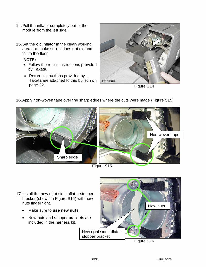
Figure S14
16. Apply non-woven tape over the sharp edges where the cuts were made (Figure S15).
Figure S15
Figure S16
14. Pull the inflator completely out of the module from the left side.
15. Set the old inflator in the clean working
area and make sure it does not roll and fall to the floor.
NOTE: Follow the return instructions provided
by Takata.
Return instructions provided by Takata are attached to this bulletin on page 22.
Non-woven tape
New nuts
17. Install the new right side inflator stopper
bracket (shown in Figure S16) with new nuts finger tight.
Make sure to use new nuts.
New nuts and stopper brackets are included in the harness kit.
New right side inflator stopper bracket
Sharp edge
Non-woven tape

16/22 NTB17-055
Reassemble Air Bag Module 18. Remove the new inflator from the box.
Figure S17
Figure S18
19. Slide the new inflator into the module
from the left side.
20. Make sure the inflator is positioned
correctly, as shown.
The flat side of the inflator end (on the right side) must face the flat side of the inflator stopper bracket.
Flat side of inflator end
Flat side of inflator stopper bracket

17/22 NTB17-055
21. Install the left side inflator stopper and 2 inflator securing nuts finger tight (see Figure S19).
Make sure to use new nuts. New nuts are included with the new inflator.
22. Make sure the inflator is pushed all the way into its housing (see Figure S19). 23. Make sure there is no gap between the inflator stoppers and the inflator (see Figure S19).
Figure S19
No gap between stopper and inflator No gap between stopper and inflator
Left side inflator stopper
Right side inflator stopper

18/22 NTB17-055
Figure S20
Figure S21
Figure S22
24. Tighten and torque the 4 inflator securing nuts.
Torque nuts to:
3.4 N•m (0.35 kg-m, 30 in-lb).
Torque nuts in the order shown.
1
42
3
25. Attach the new harness to the inflator.
NOTE: Once the harness is connected it cannot be removed.
Remove the dust proof sticker
covering the end of the inflator.
A new harness is included with the new inflator.
Refer to Figures S21, S22, and S23.
T shape
Inflator end Inflator connector
Make sure the T shape at the inflator end aligns with the T shape of the connector.

19/22 NTB17-055
Make sure the inflator connector is fully engaged / seated (see Figure S23).
Figure S23 26. Remove the module assembly from the support and set it in the clean working area.
Figure S24
Less than 2 mm - OK
More than 2 mm - NG
27. Remove the support bracket from the
module.
Support bracket

20/22 NTB17-055
Figure S25
NOTE:
Make sure to return the removed (old / non-deployed) inflator in the box that the new inflator came in.
Follow the return instructions provided by Takata.
Return instructions provided by Takata are attached to this bulletin on page 22.
28. Attach the harness clip to the module
frame.
Harness clip
Module frame

21/22 NTB17-055
PARTS INFORMATION
DESCRIPTION PART # QUANTITY
Inflator and Harness Kit (Includes harness, module mounting bolts, inflator securing nuts, 2 inflator
stoppers, and non-woven tape)
98561-4Z60B 1
NOTE:
Make sure to return the removed (old / non-deployed) inflator in the box that the new inflator came in.
Follow the return instructions provided by Takata.
Return instructions supplied by Takata are attached to this bulletin on page 22. CLAIMS INFORMATION
NOTE: Use the VIN and Service Comm to determine the correct campaign identification number for a given vehicle. The correct number must appear on all communication and documentation of any nature dealing with this campaign.
Submit a “CM” line claim using the following claims coding:
CAMPAIGN (“CM”) I.D. DESCRIPTION OP CODE FRT
PM683 Sentra – Inspect Inflator, OK.
Do not replacePM6831 0.4 hrs.
CAMPAIGN (“CM”) I.D. DESCRIPTION OP CODE FRT
PM683 Sentra – Remove and replace front passenger air bag inflator
PM6830 0.7 hrs.

22/22 NTB17-055
Takata Document