volvo diesel engine tad941ge - mototech · workshop manual volvo diesel engine tad941ge 7745012 –...
TRANSCRIPT
Workshop manual
VVOOLLVVOO
DDiieesseell eennggiinnee
TTAADD994411GGEE
7745012 – 7745022 - 7746032
33525070201_1_1

Workshop Manual
Group 20 Technical Data
TAD940GE, TAD941GETAD940VE, TAD941VE, TAD942VE, TAD943VE
I
1(0)
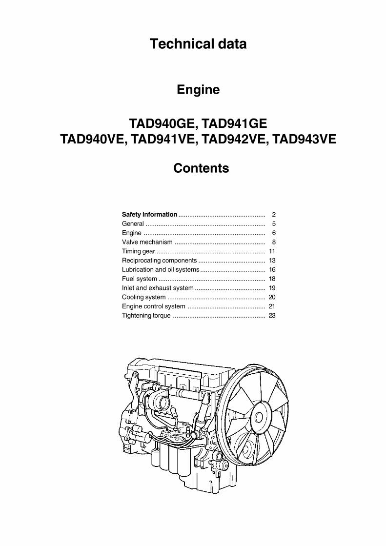
Technical data
Engine
TAD940GE, TAD941GETAD940VE, TAD941VE, TAD942VE, TAD943VE
Contents
Safety information ................................................ 2General .................................................................. 5Engine ................................................................... 6Valve mechanism .................................................. 8Timing gear ............................................................ 11Reciprocating components ..................................... 13Lubrication and oil systems.................................... 16Fuel system ........................................................... 18Inlet and exhaust system ....................................... 19Cooling system ...................................................... 20Engine control system ........................................... 21Tightening torque ................................................... 23
Group 20
Safety information
This workshop manual contains technical data, de-scriptions and repair instructions for the Volvo Pentaproducts or product versions noted in the table of con-tents. Make sure that you use the correct workshopliterature.
ImportantThe following special warning signs are used in theworkshop manual and on the product.
WARNING! Warns for the risk of personal injury,major damage to product or property, or seriousmalfunctions if the instruction is ignored.
IMPORTANT! Is used to call attention to thingswhich could cause damage or malfunctions toproduct or property.
NOTE! Is used to call attention to important informa-tion, to facilitate work processes or operation.
To give you a perspective on the risks which alwaysneed to be observed and precautions which alwayshave to be taken, we have noted them below.
Make it impossible to start the engine by cuttingsystem current with the main switch(es) andlock it (them) in the off position before startingservice work. Fix a warning sign by the controlstation.
All service work should normally be done on astationary engine. Some work, such as adjust-ments, need the engine to be running, however.Going close to a running engine is a safety risk.Remember that loose clothes, long hair etc. cancatch on rotating components and cause severeinjury.If work is done adjacent to a running engine, acareless movement or a dropped tool can leadto personal injury in the worst case. Take careto avoid contact with hot surfaces (exhaustpipes, turbocharger, charge air pipe, starterheater etc.) and hot fluids in pipes and hoses inan engine which is running or has just beenstopped. Reinstall all protective parts removedduring service operations before starting the en-gine.
Read the available safety information, ”General in-formation” and ”Repair instructions” in the work-shop manual before you start to do any servicework.
Check that the warning or information labels onthe product are always clearly visible. Replacelabels which have been damaged or paintedover.
Never start the engine without installing the aircleaner (ACL) filter. The rotating compressor tur-bine in the turbocharger can cause severe inju-ry. Foreign objects entering the intake ducts canalso cause mechanical damage.
Never use start spray or similar products as astarting aid. They may cause an explosion inthe inlet manifold. Danger of personal injury.
Only start the engine in a well- ventilated area.When operated in a confined space, exhaustfumes and crankcase gases must be ventilatedfrom the engine bay or workshop area.
Avoid opening the coolant filling cap when theengine is hot. Steam or hot coolant can sprayout and the system pressure will be lost. Whenneeded, open the filler cap slowly and releasethe pressure in the system. Be extremely care-ful if a tap, plug or coolant hose has to be re-moved from a hot engine. It is difficult to antici-pate in which direction steam or hot coolant canspray out.
Hot oil can cause burns. Avoid skin contact withhot oil. Ensure that the lubrication system is notunder pressure before carrying out any work.Never start or operate the engine with the oil fill-er cap removed, otherwise oil could be ejected.
General instructionsGroup 20
Stop the engine before carrying out operationson the engine cooling system.
Always use protective glasses or goggles whencarrying out work where there is a risk of splin-ters, grinding sparks, acid splashes or whereother chemicals are used. Your eyes are ex-tremely sensitive, injury could cause blindness!
Avoid getting oil on your skin! Repeated expo-sure to oil or exposure over a long period can re-sult in the skin becoming dry. Irritation, drynessand eczema and other skin problems can thenoccur. Used oil is more dangerous than fresh oilfrom a health aspect. Use protective gloves andavoid oil soaked clothes and shop rags. Washregularly, especially before eating. There arespecial skin creams which counteract drying outof the skin and make it easier to clean off dirtafter work is completed.
Most chemicals intended for the product (e.g.engine and transmission oils, glycol, petrol (gas-oline) and diesel oil) or chemicals for workshopuse (e.g. degreasers, paints and solvents) arehazardous. Read the instructions on the productpackaging with care! Always follow the safetyprecautions for the product (for example use ofprotective mask, glasses, gloves etc.). Makesure that other personnel are not exposed tohazardous chemicals, for example in the air. En-sure good ventilation in the work place. Followthe instructions provided when disposing ofused or leftover chemicals.
Exercise extreme care when leak detecting onthe fuel system and testing the fuel injector noz-zles. Use eye protection. The jet from a fuel in-jector is under very high pressure, and has con-siderable penetration ability; fuel can force itsway deep into body tissues and cause seriousdamage. Danger of blood poisoning (septice-mia).
WARNING! The delivery pipes must under nocircumstances be bent. Damaged pipes must bereplaced.
All fuels, and many chemicals, are flammable.Do not allow naked flame or sparks in the vicini-ty. Certain thinners and hydrogen from batteriescan be extremely flammable and explosivewhen mixed with air in the right proportions. NoSmoking! Ensure that the work area is well ven-tilated and take the necessary safety precau-tions before starting welding or grinding work. Al-ways ensure that there are fire extinguishers athand when work is being carried out.
Make sure that oil and fuel soaked rags, andused fuel and oil filters are stored in a safeplace. Rags soaked in oil can spontaneously ig-nite under certain circumstances. Used fuel andoil filters are polluting waste and must be hand-ed to an approved waste management facilityfor destruction, together with used lubrication oil,contaminated fuel, paint residue, solvents, de-greasers and wash residue.
Batteries must never be exposed to openflames or electric sparks. Do not smoke closeto the batteries. The batteries generate hydro-gen gas when charged, which forms an explo-sive gas when mixed with air. This gas is easilyignited and highly volatile. A spark, which canbe formed if the batteries are wrongly connect-ed, is enough to make a battery explode andcause damage. Do not shift the connectionswhen attempting to start the engine (spark risk)and do not lean over any of the batteries.
Never mix up the battery positive and negativepoles when the batteries are installed. Incorrectinstallation can result in serious damage to theelectrical equipment. Refer to the wiring dia-gram.
Always use protective goggles when chargingand handling the batteries. Battery electrolytecontains sulfuric acid, which is highly corrosive.Should the battery electrolyte come into contactwith unprotected skin wash off immediately us-ing plenty of water and soap. If you get batteryacid in your eyes, flush it off at once with a gen-erous amount of water, and get medical assis-tance at once.
General instructions
4
Group 20
Turn the engine off and turn off the power at themain switch(es) before carrying out work on theelectrical system.
The clutch must be adjusted with the engineshut off.
The existing lugs on the engine should be usedfor lifting. Always check that the lifting devisesare in good condition and that they have the cor-rect capacity for the lift (the weight of the engineplus the reversing gear and extra equipment).The engine should be lifted with a customized oradjustable lifting boom for safe handling and toavoid damaging components on top of the en-gine. All chains or cables must be parallel toeach other and should be as square as possibleto the top of the engine.If other equipment connected to the engine hasaltered its center of gravity, special lifting devis-es may be needed to obtain the correct balanceand safe handling.Never do any work on an engine which justhangs from a liftingdevise.
Never work alone when heavy components areto be dismantled, even when safe lifting devisessuch as lockable blocks & tackle are used.When using a lifting devise, two people are usu-ally required to do the work, one to take care ofthe lifting device and another to ensure thatcomponents are lifted clear and not damagedduring the lifting operations.Always make sure that there is enough spacefor disassembly where you are working, with norisk for personal or material damage.
WARNING! Components in the electrical andfuel systems on Volvo Penta products havebeen designed to minimize the risks of explo-sion and fire. The engine must not be operatedin environments with adjacent explosive media.
Only use the fuels recommended by Volvo Pen-ta. Refer to the Instruction Book. Use of fuelsthat are of a lower quality can damage the en-gine. In a diesel engine, poor fuel can cause thecontrol rod to bind and the engine will over- rev,entailing a strong risk of personal injury and ma-chinery damage. Poor fuel can also lead tohigher maintenance costs.
Remember the following when washing with ahigh pressure washer: Never aim the water jet atair filters, seals, rubber hoses or electrical com-ponents. Never use a high pressure washer forengine cleaning.
The injectors can leak fuel when the engine isstationary, if the tank is higher than the engineand the fuel pressure is positive.
5
Group 20
General information
Certified enginesThe manufacturer certifies that both new engines andthose in use, which are certified for national or region-al legislation, comply with the environmental require-ments. Each product must correspond with the unitused for certification. The following requirements forservice and spare parts must be complied with, forVolvo Penta as a manufacturer to be responsible forensuring that engines in use comply with the stipulat-ed environmental requirements:
• Maintenance and service intervals recommendedby Volvo Penta must be complied with.
• Only Volvo Penta Original Spare Parts intendedfor the certified engine version may be used
• Service related to injection pumps and injectorsmust always be done by an authorized Volvo Pen-ta workshop.
• The engine must not be converted or modified inany way, except for the accessories and servicekits which Volvo Penta has approved for the en-gine.
• Installation changes to the exhaust pipe and theengine bay air inlet ducts (ventilation ducts) mustnot be done without further discussion, since thiscould affect exhaust emissions.
• No seals may be broken by unauthorized person-nel.
The general advice in the instruction book about oper-ation, care and maintenance applies.
IMPORTANT! When spare parts are needed,use only Volvo Penta Original Spares.
Use of non-original spareparts means that ABVolvo Penta can no longer be responsible forguaranteeing that the engine complies with thecertified version.
Any damage, injury and/or costs which arise dueto the use of non-original Volvo Penta spares forthe product in question will not be compensatedby Volvo Penta.
About the workshop manualThis workshop manual contains technical data for theTAD940GE, TAD941GE, TAD940VE, TAD941VE,TAD942VE and TAD943VE engines.
The Workshop Manual, Technical Data, contains allthe references from the workshop manuals to repairinstructions for the TAD940GE, TAD941GE,TAD940VE, TAD941VE, TAD942VE and TAD943VEseries.
The Workshop Manual is produced primarily for theuse of Volvo Penta workshops and service techni-cians. For this reason the manual presupposes a cer-tain basic knowledge and that the user can carry outthe mechanical/electrical work described to a generalstandard of engineering competence.
Volvo Penta constantly improves its products, so wereserve the right to make modifications without priornotification. All information in this manual is based onproduct data which was available up to the date onwhich the manual was printed. Any material changesintroduced into the product or service methods afterthis date are notified by means of Service Bulletins.
Spare partsSpare parts for electrical and fuel systems are subjectto various national safety requirements. Volvo PentaOriginal Spares comply with these requirements. Nodamage whatever, occasioned by use of non-originalVolvo Penta spares for the product, will be compen-sated by the warranty offered by Volvo Penta.
6
Group 20
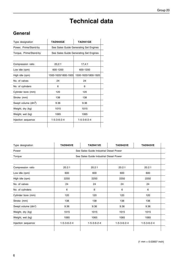
Type designation TAD940VE TAD941VE TAD942VE TAD943VE
Power See Sales Guide Industrial Diesel Power
Torque See Sales Guide Industrial Diesel Power
Compression ratio 20.2:1 20.2:1 20.2:1 20.2:1
Low idle (rpm) 600 600 600 600
High idle (rpm) 2250 2250 2250 2250
No. of valves 24 24 24 24
No. of cylinders 6 6 6 6
Cylinder bore (mm) 120 120 120 120
Stroke (mm) 138 138 138 138
Swept volume (dm3) 9.36 9.36 9.36 9.36
Weight, dry (kg) 1015 1015 1015 1015
Weight, wet (kg) 1065 1065 1065 1065
Injection sequence 1-5-3-6-2-4 1-5-3-6-2-4 1-5-3-6-2-4 1-5-3-6-2-4
Technical data
General
Type designation TAD940GE TAD941GE
Power, Prime/Stand-by See Sales Guide Generating Set Engines
Torque, Prime/Stand-by See Sales Guide Generating Set Engines
Compression ratio 20,2:1 17,4:1
Low idle (rpm) 600-1200 600-1200
High idle (rpm) 1500-1620/1800-1920 1500-1620/1800-1920
No. of valves 24 24
No. of cylinders 6 6
Cylinder bore (mm) 120 120
Stroke (mm) 138 138
Swept volume (dm3) 9.36 9.36
Weight, dry (kg) 1015 1015
Weight, wet (kg) 1065 1065
Injection sequence 1-5-3-6-2-4 1-5-3-6-2-4
(1 mm = 0.03937 inch)
Technical data
7
Group 20
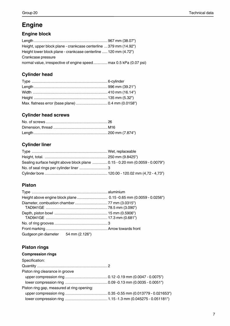
EngineEngine blockLength .................................................................... 967 mm (38.07")Height, upper block plane - crankcase centerline ... 379 mm (14.92")Height lower block plane - crankcase centerline ..... 120 mm (4.72")Crankcase pressurenormal value, irrespective of engine speed............. max 0.5 kPa (0.07 psi)
Cylinder headType ...................................................................... 6-cylinderLength .................................................................... 996 mm (39.21")Width ..................................................................... 410 mm (16.14")Height .................................................................... 135 mm (5.32")Max. flatness error (base plane) ............................. 0.4 mm (0.0158")
Cylinder head screwsNo. of screws ......................................................... 26Dimension, thread ..................................................M16Length .................................................................... 200 mm (7.874")
Cylinder linerType ...................................................................... Wet, replaceableHeight, total. .......................................................... 250 mm (9.8425")Sealing surface height above block plane .............. 0.15 - 0.20 mm (0.0059 - 0.0079")No. of seal rings per cylinder liner .......................... 3Cylinder bore .......................................................... 120.00 - 120.02 mm (4,72 - 4,73”)
PistonType ...................................................................... aluminiumHeight above engine block plane ............................ 0.15 -0.65 mm (0.0059 - 0.0256")Diameter, combustion chamber .............................. 77 mm (3.0315")
TAD941GE ......................................................... 78.5 mm (3.090”)Depth, piston bowl ................................................. 15 mm (0.5906")
TAD941GE ......................................................... 17.3 mm (0.681”)No. of ring grooves ................................................. 3Front marking .........................................................Arrow towards frontGudgeon pin diameter 54 mm (2.126")
Piston ringsCompression rings
Specification:Quantity ................................................................. 2Piston ring clearance in groove
upper compression ring ....................................... 0.12 -0.19 mm (0.0047 - 0.0075")lower compression ring ....................................... 0.09 -0.13 mm (0.0035 - 0.0051")
Piston ring gap, measured at ring opening:upper compression ring ....................................... 0.35 -0.55 mm (0.013779 - 0.021653")lower compression ring ....................................... 1.15 -1.3 mm (0.045275 - 0.051181")
Technical data
8
Group 20
Oil scraper ring:Quantity ................................................................. 1Width, including spring ........................................... 4.3 mm (0.011811")Piston ring clearance in groove, ............................. 0.05 -0.10 mm (0.001968 - 0.003937")Piston ring gap, measured at ring opening .............. 0.35 -0.75 mm (0.013779 - 0.029527")
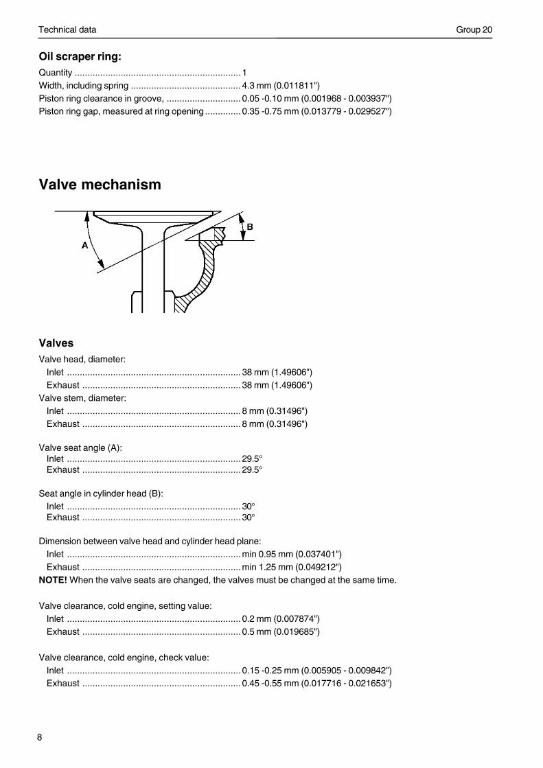
Valve mechanism
ValvesValve head, diameter:
Inlet .................................................................... 38 mm (1.49606")Exhaust .............................................................. 38 mm (1.49606")
Valve stem, diameter:Inlet .................................................................... 8 mm (0.31496")Exhaust .............................................................. 8 mm (0.31496")
Valve seat angle (A):Inlet .................................................................... 29.5°Exhaust .............................................................. 29.5°
Seat angle in cylinder head (B):Inlet .................................................................... 30°Exhaust .............................................................. 30°
Dimension between valve head and cylinder head plane:Inlet ....................................................................min 0.95 mm (0.037401")Exhaust ..............................................................min 1.25 mm (0.049212")
NOTE! When the valve seats are changed, the valves must be changed at the same time.
Valve clearance, cold engine, setting value:Inlet .................................................................... 0.2 mm (0.007874")Exhaust .............................................................. 0.5 mm (0.019685")
Valve clearance, cold engine, check value:Inlet .................................................................... 0.15 -0.25 mm (0.005905 - 0.009842")Exhaust .............................................................. 0.45 -0.55 mm (0.017716 - 0.021653")
Technical data
9
Group 20
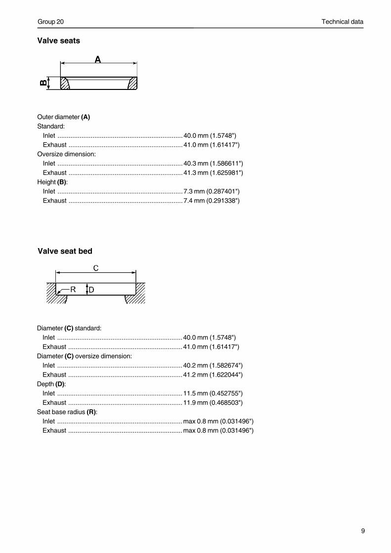
Valve seats
Outer diameter (A)Standard:
Inlet .................................................................... 40.0 mm (1.5748")Exhaust .............................................................. 41.0 mm (1.61417")
Oversize dimension:Inlet .................................................................... 40.3 mm (1.586611")Exhaust .............................................................. 41.3 mm (1.625981")
Height (B):Inlet .................................................................... 7.3 mm (0.287401")Exhaust .............................................................. 7.4 mm (0.291338")
Valve seat bed
Diameter (C) standard:Inlet ....................................................................40.0 mm (1.5748")Exhaust ..............................................................41.0 mm (1.61417")
Diameter (C) oversize dimension:Inlet ....................................................................40.2 mm (1.582674")Exhaust ..............................................................41.2 mm (1.622044")
Depth (D):Inlet ....................................................................11.5 mm (0.452755")Exhaust ..............................................................11.9 mm (0.468503")
Seat base radius (R):Inlet ....................................................................max 0.8 mm (0.031496")Exhaust ..............................................................max 0.8 mm (0.031496")
Technical data
10
Group 20
Valve guidesLength:
Inlet .................................................................... 83.4 mm (3.283458")Exhaust .............................................................. 83.4 mm (3.283458")
Inner diameter:Inlet .................................................................... 8 mm (0.31496")Exhaust .............................................................. 8 mm (0.31496")
Height above cylinder head spring plane:Inlet .................................................................... 24.5±0.5 mm (0.964564 ± 0.019685")Exhaust .............................................................. 16.5±0.5 mm (0.6496043 ± 0.019685")
Clearance, valve stem - guide:1Inlet ....................................................................max 0.2 mm (0.007874")Exhaust ..............................................................max 0.2 mm (0.007874")
1 The dimensions have been calculated for the method of measurement described in the workshop manual (group 21).
Rocker armsBearing clearance ..................................................max 0.08 mm
Valve springsInletOuter valve springs:
Unloaded length .................................................. 73.8 mm (2.905506")With 590 N (132.6 lbf) loading ............................. 58.4 mm (2.299208")With 1150 N (258.5 lbf) loading ........................... 45.3 mmCoilbound length, max......................................... 39.5 mm (1.555115")
Inner valve spring:Unloaded length .................................................. 70.5 mm (2.775585")With 243 N (54.6 lbf) loading ............................... 54.4 mm (2.141728")With 447 N (100.4 lbf) loading ............................. 41.3 mm (1.625981")Coilbound length, max......................................... 36.5 mm (1.437005")
ExhaustOuter valve springs:
Unloaded length .................................................. 73.8 mm (2.905506")With 590 N (132.6 lbf) loading ............................. 58.4 mm (2.299208")With 1150 N (258.5 lbf) loading ........................... 45.3 mm (1.783461")Coilbound length, max......................................... 39.5 mm (1.555115")
Inner valve spring:Unloaded length .................................................. 70.5 mm (2.775585")With 243 N (54.6 lbf) loading ............................... 54.4 mm (2.141728")With 447 N (100.4 lbf) loading ............................. 41.3 mm (1.625981")Coilbound length, max......................................... 36.5 mm (1.437005")
Technical data
11
Group 20
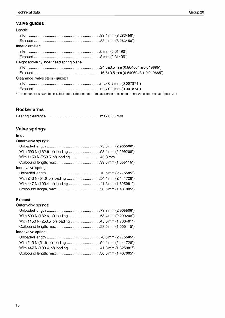
Timing gearTiming gear wheels
No. of teeth:1. Drive gear, crankshaft .......................................... 54
2. Idler wheel, double, outer ...................................... 72
Idler wheel, double, inner ...................................... 56
3. Idler wheel, adjustable .......................................... 73
4. Drive gear, camshaft ............................................ 84
5. Idler wheel, servo pump........................................ 37
6. Drive wheel, steering servo and fuel feed pump .... 31
7. Drive wheel, air compressor ................................. 42
8. Drive wheel, lubricating oil pump .......................... 23
Gear backlashmin ..................................................................... 0.05 mm (0.001968")max ....................................................................0.17 mm (0.006692")
Shaft stub for idler wheel, diameter ........................ 100 mm (3.937")Bushing for idler wheel, diameter ............................ 100 mm (3.937")Radial clearance for idler wheel ..............................max 0.05 mm (0.001968")
Technical data
12
Group 20
CamshaftCheck camshaft setting, cold engine and valve clearance =0.Inlet valve for cylinder 1 at flywheel position 6 ATDC must be open 1.3±0.3 mm (0.05118±0.0118").During the check, you must turn the timing gear in the correct direction (clockwise seenfrom the front), to take up all gear flank clearance.
Drive ...................................................................... gear wheelNo of bearings ........................................................ 7Diameter, bearing journals, standard ...................... 69.97 -70.00 mm (22.754718 - .7559")NOTE! Only check values, not for machining.
Diameter, bearing journals, undersize dimension0.25 .................................................................... 69.72 -69.78 mm (2.744876 - 2.747238")0.50 .................................................................... 69.47 -69.53 mm (2.735033 - 2.737396")0.75 .................................................................... 69.22 -69.28 mm (2.725191 - 2.727553")
Max. end float ........................................................ 0.24 mm (0.009448")Max permissible ovality (with new bearings) ........... 0.05 mm (0.001968")Bearing, max. permissible wear on diameter .......... 0.05 mm (0.001968")Valve lift:
inlet ..................................................................... 13 mm (0.51181")outlet (EPG) ........................................................ 12 mm (0.47244")
Permissible wear between base circleand max. lift ....................................................... max 0.1 mm (0.003937")
Unit injector, stroke ................................................ 13 mm (0.51181")
Camshaft bearingsCamshaft bearing thickness, standard ................... 1.92 mm (0.075590")Oversize dimension:
0.25 .................................................................... 2.04 mm (0.080314")0.50 .................................................................... 2.17 mm (0.085432")0.75 .................................................................... 2.29 mm (0.090157")
Technical data
13
Group 20
Reciprocating components
Crankshaft
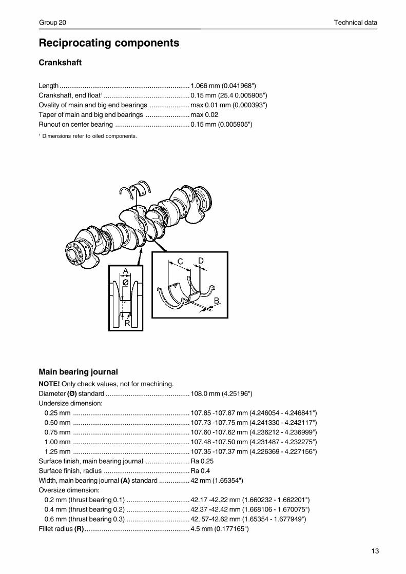
Length .................................................................... 1.066 mm (0.041968")Crankshaft, end float1 ............................................. 0.15 mm (25.4 0.005905")Ovality of main and big end bearings .....................max 0.01 mm (0.000393")Taper of main and big end bearings .......................max 0.02Runout on center bearing ....................................... 0.15 mm (0.005905")1 Dimensions refer to oiled components.
Main bearing journalNOTE! Only check values, not for machining.Diameter (Ø) standard ............................................ 108.0 mm (4.25196")Undersize dimension:
0.25 mm ............................................................. 107.85 -107.87 mm (4.246054 - 4.246841")0.50 mm ............................................................. 107.73 -107.75 mm (4.241330 - 4.242117")0.75 mm ............................................................. 107.60 -107.62 mm (4.236212 - 4.236999")1.00 mm ............................................................. 107.48 -107.50 mm (4.231487 - 4.232275")1.25 mm ............................................................. 107.35 -107.37 mm (4.226369 - 4.227156")
Surface finish, main bearing journal .......................Ra 0.25Surface finish, radius .............................................Ra 0.4Width, main bearing journal (A) standard ................ 42 mm (1.65354")Oversize dimension:
0.2 mm (thrust bearing 0.1) ................................. 42.17 -42.22 mm (1.660232 - 1.662201")0.4 mm (thrust bearing 0.2) ................................. 42.37 -42.42 mm (1.668106 - 1.670075")0.6 mm (thrust bearing 0.3) ................................. 42, 57-42.62 mm (1.65354 - 1.677949")
Fillet radius (R) ....................................................... 4.5 mm (0.177165")
Technical data
14
Group 20
Thrust washers (thrust bearing)Width (B) standard ................................................. 3.2 mm (0.125984")Oversize dimension:
0.1 mm ............................................................... 3.2 -3.3 mm (0.125984 - 0.129921")0.2 mm ............................................................... 3.3 -3.4 mm (0.129921 - 0.133858")0.3 mm ............................................................... 3.4 -3.5 mm (0.133858 - 0.137795")
Main bearing shellsOuter diameter (C) ................................................. 113 mm (4.44881")Thickness (D) standard .......................................... 2.5 mm (0.098425")Oversize dimension:
0.25 mm ............................................................. 2.6 -2.7 mm (0.102362 - 0.106299")0.50 mm ............................................................. 2.7 -2.8 mm (0.106299 - 0.110236")0.75 mm ............................................................. 2.8 -2.9 mm (0.110236 - 0.114173")1.00 mm ............................................................. 2.9 -3.0 mm (0.114173 - 0.11811")1.25 mm ............................................................. 3.1-3.2 mm (0.122047 - 0.125984")
Radial clearance, main bearings .............................max 0.11 mm (0.004330")
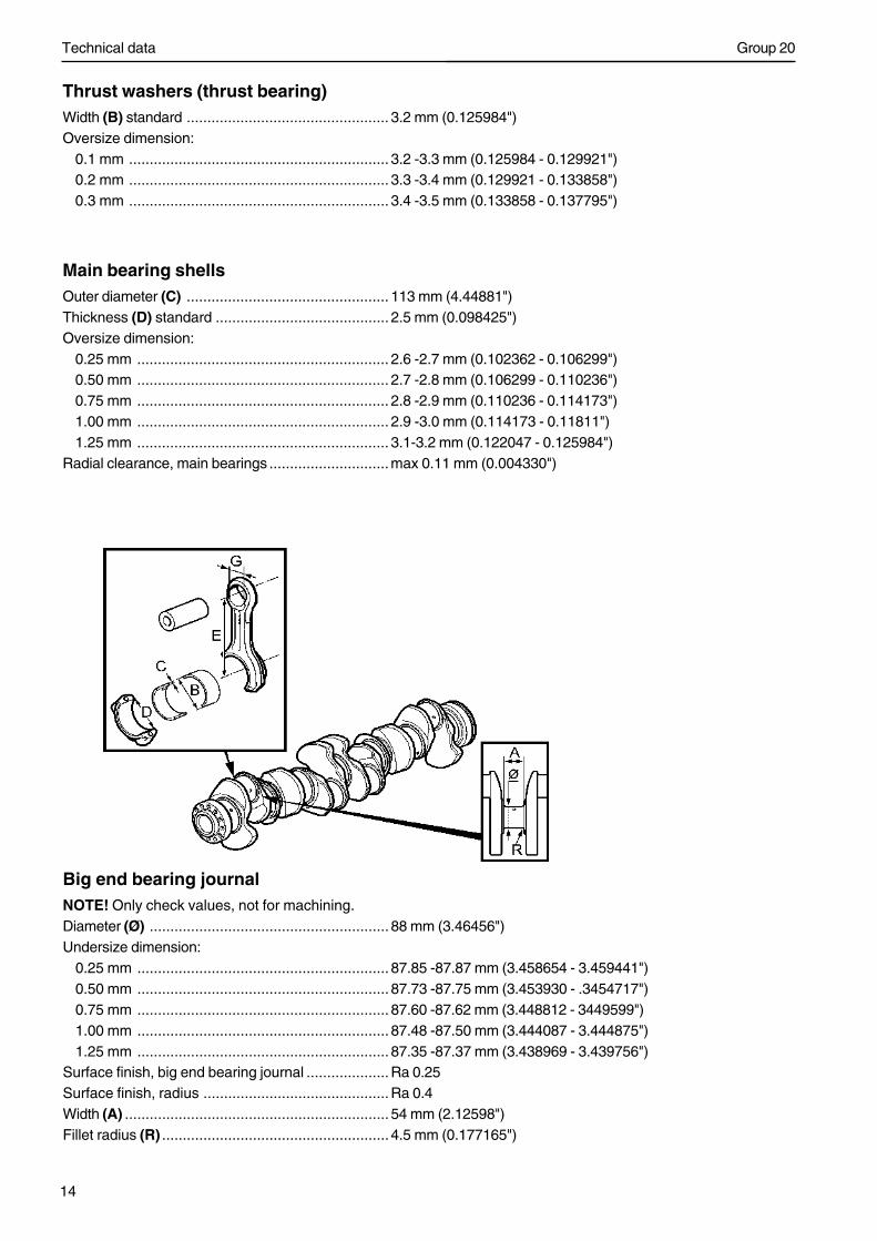
Big end bearing journalNOTE! Only check values, not for machining.Diameter (Ø) .......................................................... 88 mm (3.46456")Undersize dimension:
0.25 mm ............................................................. 87.85 -87.87 mm (3.458654 - 3.459441")0.50 mm ............................................................. 87.73 -87.75 mm (3.453930 - .3454717")0.75 mm ............................................................. 87.60 -87.62 mm (3.448812 - 3449599")1.00 mm ............................................................. 87.48 -87.50 mm (3.444087 - 3.444875")1.25 mm ............................................................. 87.35 -87.37 mm (3.438969 - 3.439756")
Surface finish, big end bearing journal ....................Ra 0.25Surface finish, radius .............................................Ra 0.4Width (A) ................................................................ 54 mm (2.12598")Fillet radius (R) ....................................................... 4.5 mm (0.177165")
Technical data
15
Group 20
Big end journal shellsOuter diameter (B) ................................................. 93 mm (3.66141")Thickness (C) standard .......................................... 2.4 mm (0.094488")Oversize dimension:
0.25 mm ............................................................. 2.5 -2.6 mm (0.098425 - 0.102362")0.50 mm ............................................................. 2.6 -2.7 mm (0.102362 - 0.106299")0.75 mm ............................................................. 2.7 -2.8 mm (0.106299 - 0.110236")1.00 mm ............................................................. 2.8 -2.9 mm (0.110236 - 0.114173")1.25 mm ............................................................. 3.0 -3.1 mm (0.11811 - 0.122047")
Diameter, bearing shell seat (D) ............................. 92.85 mm (3.655504")
Con rodsLength, center - center (E) ..................................... 225 mm (8.85825")Small end bushing, internal diameter (G) ................ 54 mm (2.12598")End float, con rod - crankshaft1: .............................max 0.35 mm (0.013779")Big end bearing, radial clearance 1: .......................max 0.10 mm (0.003937")Straightness, max. deviation on 100 mm (3.937")measured length .................................................... 0.06 mm (0.002362")Twist, max. deviation on 100 mm (3.937")measured length .................................................... 0.15 mm (0.005905")1 Dimensions refer to oiled components.
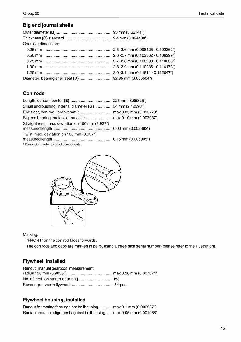
Marking:”FRONT” on the con rod faces forwards.The con rods and caps are marked in pairs, using a three digit serial number (please refer to the illustration).
Flywheel, installedRunout (manual gearbox), measurementradius 150 mm (5.9055") . ......................................max 0.20 mm (0.007874")No. of teeth on starter gear ring .............................. 153Sensor grooves in flywheel .................................... 54 pcs.
Flywheel housing, installedRunout for mating face against bellhousing. ...........max 0.1 mm (0.003937")Radial runout for alignment against bellhousing. .....max 0.05 mm (0.001968")
Technical data
16
Group 20
Lubrication oil systems
OilOil change volume, including filters ........................35 liter (9.2 US gallon)
Oil pressureOperating speed (above 1100 rpm) ......................... 300 -550 kPa (43.5-79.7 psi)Low idle ..................................................................min 270 kPa (39.1 psi)
Oil temperatureCold engine, engine stopped .................................. ambient temperatureHot engine, engine running
(coolant temperature 75-95 C) (167-203°F) .......... 90-115 C (194-239°F)
Lubricating oil pumpType ...................................................................... Gear drivenNo. of teeth, drive wheel ........................................ 23
Oil filterFull flow filter .......................................................... 2Turbo filter (By-pass filter) ...................................... 1
Technical data
17
Group 20
Oil valves
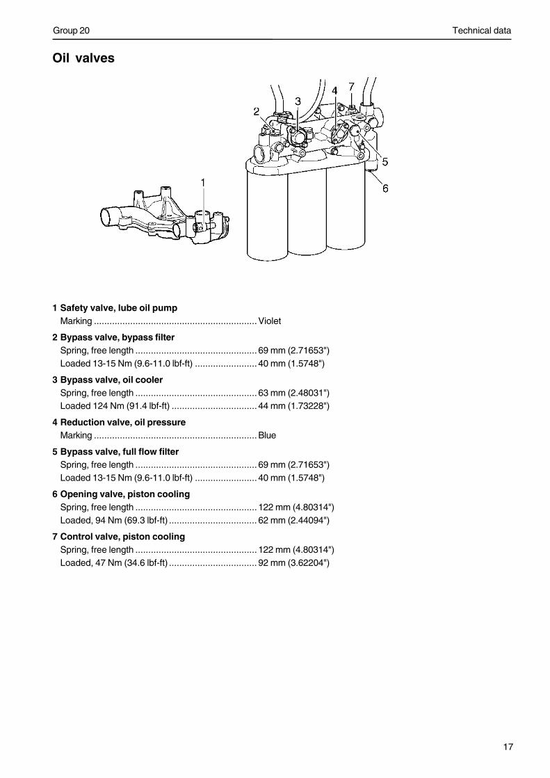
1 Safety valve, lube oil pumpMarking ...............................................................Violet
2 Bypass valve, bypass filterSpring, free length ............................................... 69 mm (2.71653")Loaded 13-15 Nm (9.6-11.0 lbf-ft) ........................ 40 mm (1.5748")
3 Bypass valve, oil coolerSpring, free length ............................................... 63 mm (2.48031")Loaded 124 Nm (91.4 lbf-ft) ................................. 44 mm (1.73228")
4 Reduction valve, oil pressureMarking ...............................................................Blue
5 Bypass valve, full flow filterSpring, free length ............................................... 69 mm (2.71653")Loaded 13-15 Nm (9.6-11.0 lbf-ft) ........................ 40 mm (1.5748")
6 Opening valve, piston coolingSpring, free length ............................................... 122 mm (4.80314")Loaded, 94 Nm (69.3 lbf-ft) .................................. 62 mm (2.44094")
7 Control valve, piston coolingSpring, free length ............................................... 122 mm (4.80314")Loaded, 47 Nm (34.6 lbf-ft) .................................. 92 mm (3.62204")
Technical data
18
Group 20
Fuel system
Feed pumpFeed pressure at:
600 r/min ............................................................. min 400 kPa (58.0 psi)1200 r/min ...........................................................min 400 kPa (58.0 psi)full load ...............................................................min 400 kPa (58.0 psi)
By-pass valveOpening pressure ................................................... 400 -550 kPa (58.0-79.7 psi)
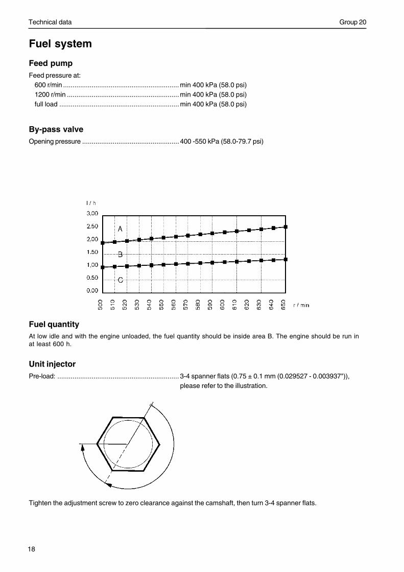
Fuel quantityAt low idle and with the engine unloaded, the fuel quantity should be inside area B. The engine should be run inat least 600 h.
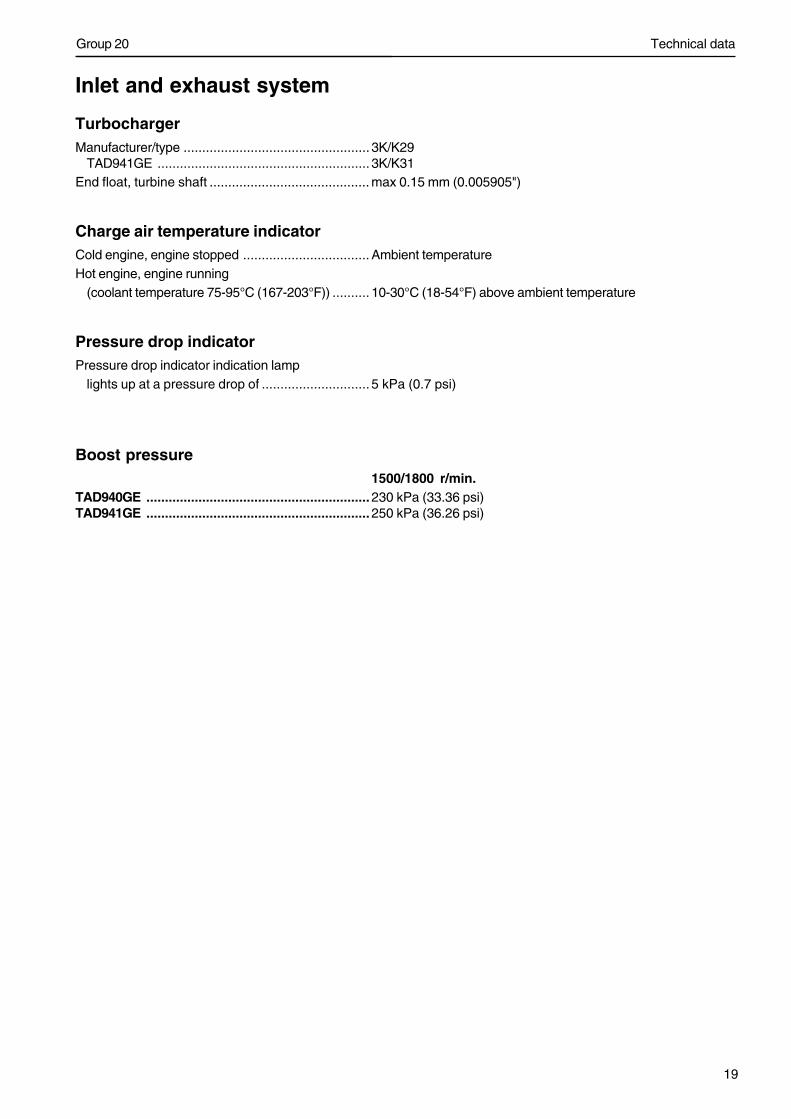
Unit injectorPre-load: ................................................................ 3-4 spanner flats (0.75 ± 0.1 mm (0.029527 - 0.003937")),
please refer to the illustration.
Tighten the adjustment screw to zero clearance against the camshaft, then turn 3-4 spanner flats.
Technical data
19
Group 20
Inlet and exhaust system
TurbochargerManufacturer/type .................................................. 3K/K29
TAD941GE ......................................................... 3K/K31End float, turbine shaft ........................................... max 0.15 mm (0.005905")
Charge air temperature indicatorCold engine, engine stopped .................................. Ambient temperatureHot engine, engine running
(coolant temperature 75-95°C (167-203°F)) .......... 10-30°C (18-54°F) above ambient temperature
Pressure drop indicatorPressure drop indicator indication lamp
lights up at a pressure drop of ............................. 5 kPa (0.7 psi)
Boost pressure1500/1800 r/min.
TAD940GE ............................................................230 kPa (33.36 psi)TAD941GE ............................................................250 kPa (36.26 psi)
Technical data
20
Group 20
Cooling system
GeneralPressure cap opens at ........................................... 75 kPa (10.8 psi)
ThermostatQuantity ................................................................. 1Opening temperature .............................................. 82°C (180°F)Fully open .............................................................. 92°C (198°F)
CoolantType ...................................................................... Volvo OriginalConsists of ............................................................Glycol and corrosion-inhibiting additivesColor ...................................................................... GreenMix with .................................................................Tap water
Corrosion inhibitor
Only used when anti-freeze is not needed.Type ...................................................................... Volvo OriginalMix with .................................................................Tap waterNOTE! The corrosion inhibitor must not be mixed with other types of coolants or corrosion inhibitors, since thiscan have adverse effects.
Technical data
21
Group 20
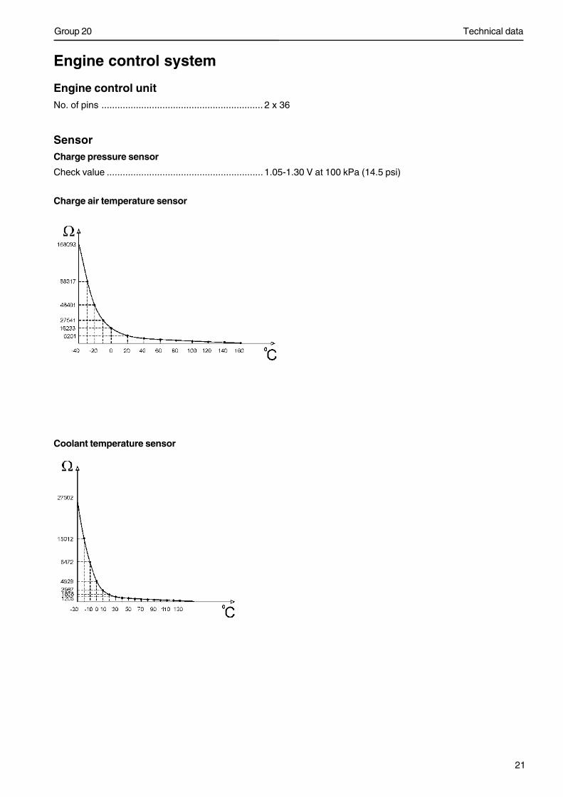
Engine control system
Engine control unitNo. of pins ............................................................. 2 x 36
SensorCharge pressure sensor
Check value ........................................................... 1.05-1.30 V at 100 kPa (14.5 psi)
Charge air temperature sensor
Coolant temperature sensor
Technical data
22
Group 20
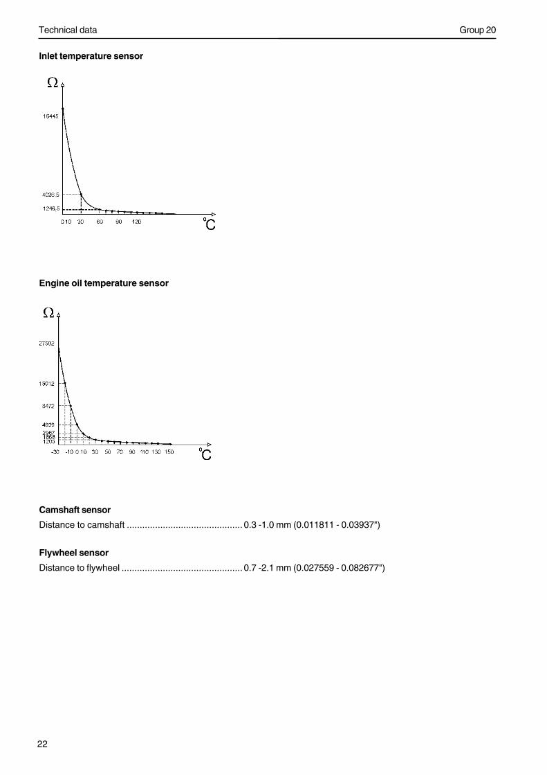
Inlet temperature sensor
Engine oil temperature sensor
Camshaft sensor
Distance to camshaft ............................................. 0.3 -1.0 mm (0.011811 - 0.03937")
Flywheel sensor
Distance to flywheel ............................................... 0.7 -2.1 mm (0.027559 - 0.082677")

Technical data
23
Group 20
Tightening torque
General tightening torque NmM6 standard screw 8.8 ........................................... 10 ±1.5 (±1.1 lbf-ft)M8 standard screw 8.8 ........................................... 25 ±4 (18.5±2.9 lbf-ft)M10 standard screw 8.8 ......................................... 50±8 (36.9±5.9 lbf-ft)M12 standard screw 8.8 ......................................... 85 ±15 (62.7±11.0 lbf-ft)M14 standard screw 8.8 ......................................... 140 ±25 (103±18.4 lbf-ft)M16 standard screw 8.8 ......................................... 220 ±35 (162±25.8 lbf-ft)
Only torqued screws can be re-installed.Torque and angle tightened / plastic limit tightened screws:
8.8 ...................................................................... should not be re-installed10.9 .................................................................... can be re-installed12.9 .................................................................... can be re-installed
IMPORTANT! Check screws which are to be re-installed. Damaged screws, with marks of seizure etc. under theheads, must be scrapped.
Tightening torque group 21: Engine bodyFront engine mounting, engine block ...................... 275 ±45 Nm (202±33lbf-ft)Front engine mounting, front engine pad................. 150 ±30 Nm (111±22 lbf-ft)Main bearing caps
Stage 1 ............................................................... 150 ±20 Nm (111±15 lbf-ft)Stage 2 ............................................................... 120° ±5° angle tightening
Big end bearing capStage 1 ............................................................... 20 ±3 Nm (15±2 lbf-ft)Stage 2 ............................................................... 35 ±3 Nm (26±2 lbf-ft)Stage 3 ............................................................... 90° ±5° angle tightening
Stiffening frame ..................................................... 48 ±8 Nm (35±6 lbf-ft)NOTE! Tighten the screws in sequence, from the center and outwards.
Technical data
24
Group 20
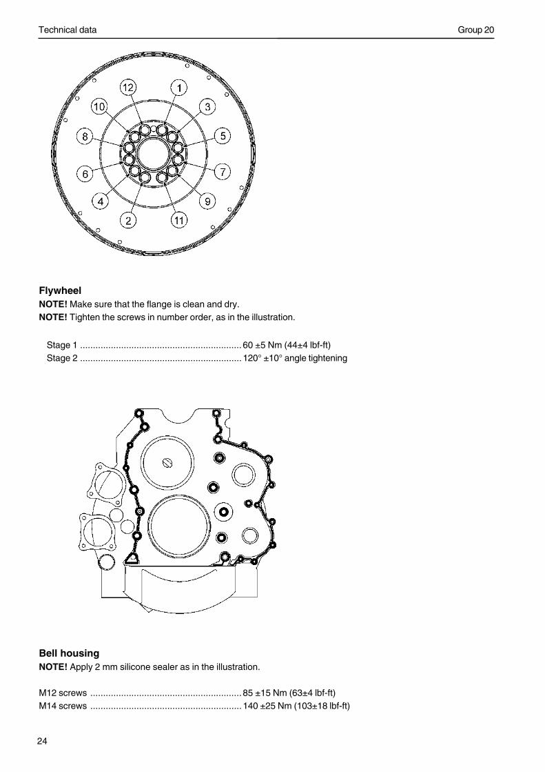
FlywheelNOTE! Make sure that the flange is clean and dry.NOTE! Tighten the screws in number order, as in the illustration.
Stage 1 ............................................................... 60 ±5 Nm (44±4 lbf-ft)Stage 2 ............................................................... 120° ±10° angle tightening
Bell housingNOTE! Apply 2 mm silicone sealer as in the illustration.
M12 screws ........................................................... 85 ±15 Nm (63±4 lbf-ft)M14 screws ........................................................... 140 ±25 Nm (103±18 lbf-ft)
Technical data
25
Group 20
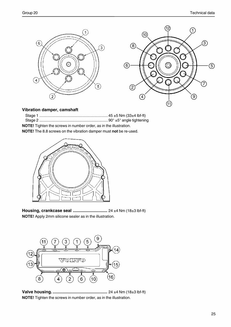
Vibration damper, camshaftStage 1 ............................................................... 45 ±5 Nm (33±4 lbf-ft)Stage 2 ............................................................... 90° ±5° angle tightening
NOTE! Tighten the screws in number order, as in the illustration.NOTE! The 8.8 screws on the vibration damper must not be re-used.
Housing, crankcase seal ............................. 24 ±4 Nm (18±3 lbf-ft)
NOTE! Apply 2mm silicone sealer as in the illustration.
Valve housing. .............................................. 24 ±4 Nm (18±3 lbf-ft)
NOTE! Tighten the screws in number order, as in the illustration.
3
1
4
2
56
7
8
10
9
12
11
Technical data
26
Group 20
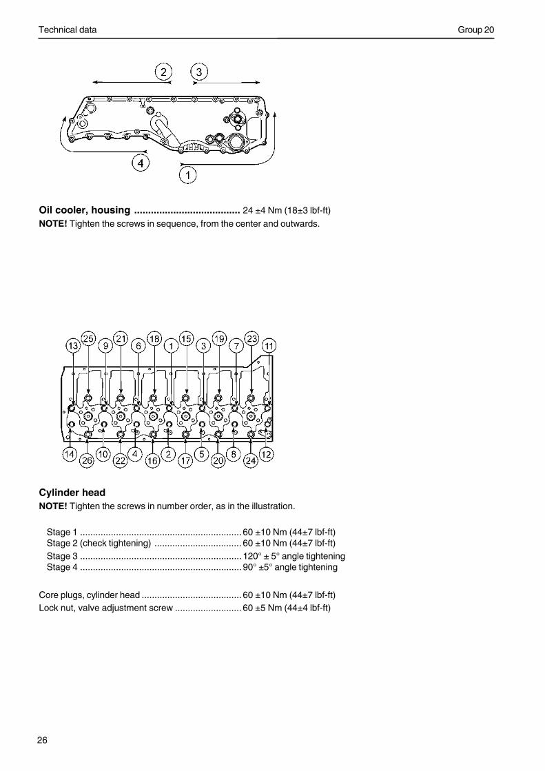
Oil cooler, housing ...................................... 24 ±4 Nm (18±3 lbf-ft)
NOTE! Tighten the screws in sequence, from the center and outwards.
Cylinder headNOTE! Tighten the screws in number order, as in the illustration.
Stage 1 ............................................................... 60 ±10 Nm (44±7 lbf-ft)Stage 2 (check tightening) .................................. 60 ±10 Nm (44±7 lbf-ft)Stage 3 ............................................................... 120° ± 5° angle tighteningStage 4 ............................................................... 90° ±5° angle tightening
Core plugs, cylinder head ....................................... 60 ±10 Nm (44±7 lbf-ft)Lock nut, valve adjustment screw .......................... 60 ±5 Nm (44±4 lbf-ft)
Technical data
27
Group 20
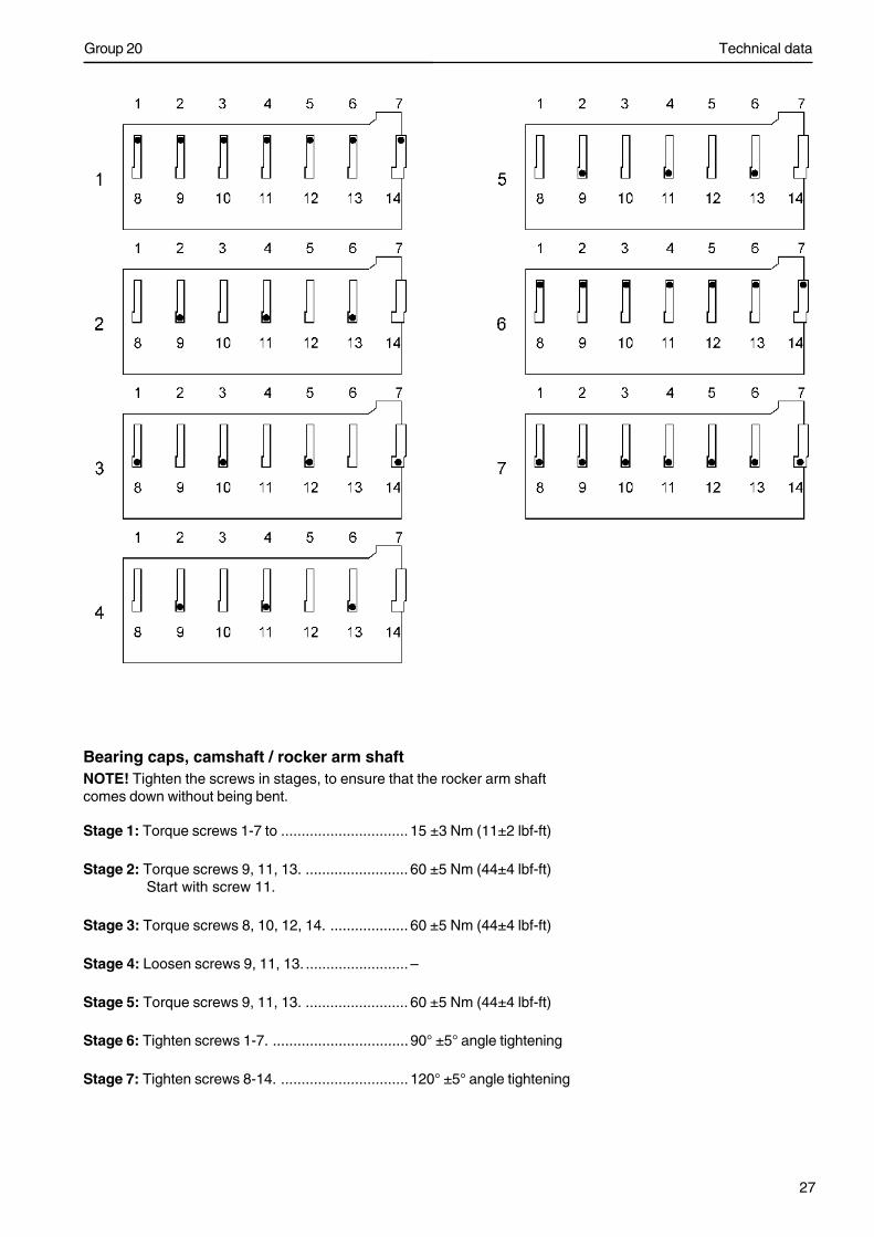
Bearing caps, camshaft / rocker arm shaftNOTE! Tighten the screws in stages, to ensure that the rocker arm shaftcomes down without being bent.
Stage 1: Torque screws 1-7 to ............................... 15 ±3 Nm (11±2 lbf-ft)
Stage 2: Torque screws 9, 11, 13. ......................... 60 ±5 Nm (44±4 lbf-ft) Start with screw 11.
Stage 3: Torque screws 8, 10, 12, 14. ................... 60 ±5 Nm (44±4 lbf-ft)
Stage 4: Loosen screws 9, 11, 13. ......................... –
Stage 5: Torque screws 9, 11, 13. ......................... 60 ±5 Nm (44±4 lbf-ft)
Stage 6: Tighten screws 1-7. ................................. 90° ±5° angle tightening
Stage 7: Tighten screws 8-14. ............................... 120° ±5° angle tightening
Technical data
28
Group 20
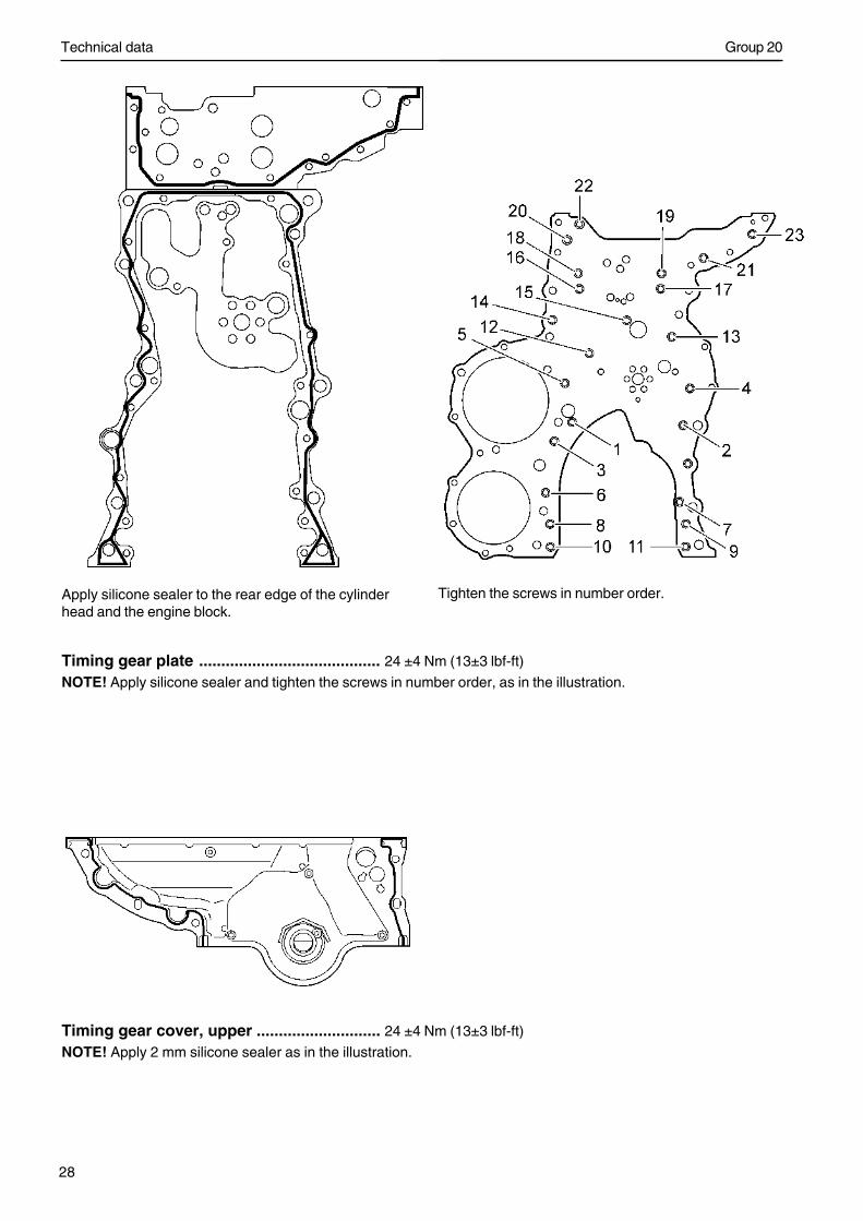
Timing gear plate ......................................... 24 ±4 Nm (13±3 lbf-ft)
NOTE! Apply silicone sealer and tighten the screws in number order, as in the illustration.
Tighten the screws in number order.Apply silicone sealer to the rear edge of the cylinderhead and the engine block.
Timing gear cover, upper ............................ 24 ±4 Nm (13±3 lbf-ft)
NOTE! Apply 2 mm silicone sealer as in the illustration.
Technical data
29
Group 20
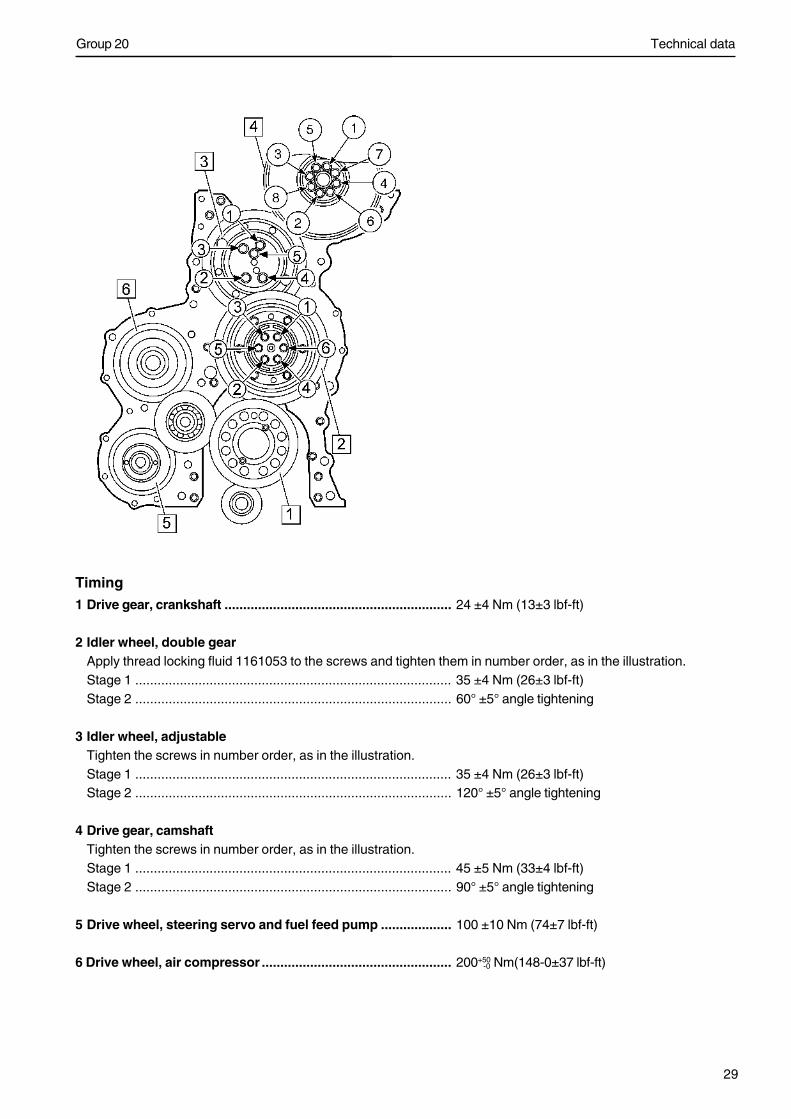
Timing1 Drive gear, crankshaft ............................................................. 24 ±4 Nm (13±3 lbf-ft)
2 Idler wheel, double gearApply thread locking fluid 1161053 to the screws and tighten them in number order, as in the illustration.Stage 1 ..................................................................................... 35 ±4 Nm (26±3 lbf-ft)Stage 2 ..................................................................................... 60° ±5° angle tightening
3 Idler wheel, adjustableTighten the screws in number order, as in the illustration.Stage 1 ..................................................................................... 35 ±4 Nm (26±3 lbf-ft)Stage 2 ..................................................................................... 120° ±5° angle tightening
4 Drive gear, camshaftTighten the screws in number order, as in the illustration.Stage 1 ..................................................................................... 45 ±5 Nm (33±4 lbf-ft)Stage 2 ..................................................................................... 90° ±5° angle tightening
5 Drive wheel, steering servo and fuel feed pump ................... 100 ±10 Nm (74±7 lbf-ft)
6 Drive wheel, air compressor ................................................... 200+50 Nm(148-0±37 lbf-ft)-0
Technical data
30
Group 20
Tightening torque group 22: Lubricating systemOil sump ................................................................ 24 ±4 Nm (18±3 lbf-ft)NOTE! Tighten the screws in sequence, from the center and outwards.
Drain plug, oil sump ............................................... 60 ±5 Nm (44±4 lbf-ft)Bracket, oil pump/main bearing caps ..................... 24 ±4 Nm (13±3 lbf-ft)Oil strainer, retaining screws .................................. 24 ±4 Nm (18±3 lbf-ft)Oil cooler, retaining screws .................................... 27 ±4 Nm (18±3 lbf-ft)
Tightening torque group 23: Fuel systemFeed pump - steering servo pump .......................... 24 ±4 Nm (18±3 lbf-ft)Fixing yoke, unit injector (new copper sleeve)First tightening
Stage 1 ............................................................... 20 ±5 Nm (15±4 lbf-ft)Stage 2 ............................................................... 180° ±5° angle tightening
Loosen the fastening yoke screw before doing the second tightening.Second tightening
Stage 1 ............................................................... 20 ±5 Nm (15±4 lbf-ft)Stage 2 ............................................................... 60° ±5° angle tightening
Fixing yoke, unit injector (re-used copper sleeve)Stage 1 ............................................................... 20 ±5 Nm (14±3 lbf-ft)Stage 2 ............................................................... 60° ±5° angle tightening
Locknut for rocker adjuster screw, unit injectorStage 1 ............................................................... tighten until contactStage 2 .............................................................. 45° ±5° angle tightening
Locknut, valve adjustmentStage 1 ............................................................... tighten until contactStage 2 ............................................................... 60° ±5° angle tightening
Hollow screw M16 x 1.5 ......................................... 50 ±8 NmHollow screw M10 x 1 ............................................ 25 ±4 Nm
Group 20
Tightening tourqe group 25, Intake and exhaust system
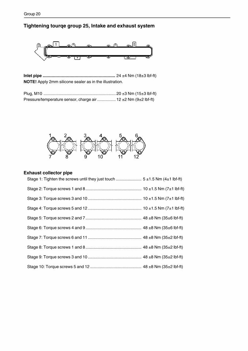
Inlet pipe ......................................................... 24 ±4 Nm (18±3 lbf-ft)
NOTE! Apply 2mm silicone sealer as in the illustration.
Plug, M10 .............................................................. 20 ±3 Nm (15±3 lbf-ft)Pressure/temperature sensor, charge air ................ 12 ±2 Nm (9±2 lbf-ft)
Exhaust collector pipeStage 1: Tighten the screws until they just touch ...................... 5 ±1.5 Nm (4±1 lbf-ft)
Stage 2: Torque screws 1 and 8 ................................................ 10 ±1.5 Nm (7±1 lbf-ft)
Stage 3: Torque screws 3 and 10 .............................................. 10 ±1.5 Nm (7±1 lbf-ft)
Stage 4: Torque screws 5 and 12 .............................................. 10 ±1.5 Nm (7±1 lbf-ft)
Stage 5: Torque screws 2 and 7 ................................................ 48 ±8 Nm (35±6 lbf-ft)
Stage 6: Torque screws 4 and 9 ................................................ 48 ±8 Nm (35±6 lbf-ft)
Stage 7: Torque screws 6 and 11 .............................................. 48 ±8 Nm (35±2 lbf-ft)
Stage 8: Torque screws 1 and 8 ................................................ 48 ±8 Nm (35±2 lbf-ft)
Stage 9: Torque screws 3 and 10 .............................................. 48 ±8 Nm (35±2 lbf-ft)
Stage 10: Torque screws 5 and 12 ............................................ 48 ±8 Nm (35±2 lbf-ft)

32

Report form
Do you have any complaints or other comments about this manual.Please make a copy of this page, write your comments down and sendthem to us. The address is at the bottom. We would prefer you to write inEnglish or Swedish.
From: ......................................................................
................................................................................
................................................................................
................................................................................
Refers to publication: ................................................................................................................................
Publication No.: .................................. Date of issue: ................................................................................
Proposal/motivation: .................................................................................................................................
.................................................................................................................................................................
.................................................................................................................................................................
.................................................................................................................................................................
.................................................................................................................................................................
.................................................................................................................................................................
.................................................................................................................................................................
.................................................................................................................................................................
.................................................................................................................................................................
Date: ..................................................................................
Signed: ..............................................................................
AB Volvo PentaTechnical Information
Dept. 42200SE-405 08 Göteborg
Sweden

7745
012
Eng
lish
06–
2005

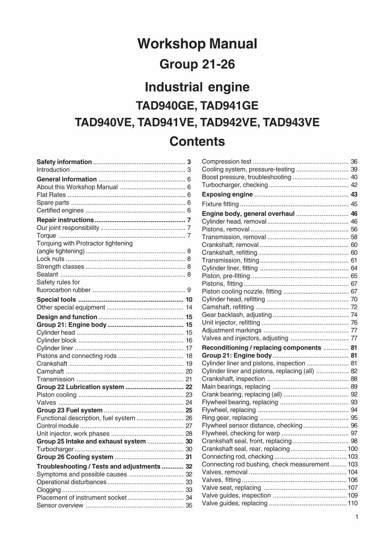
Workshop Manual
Group 21-26
TAD940GE, TAD941GETAD940VE, TAD941VE TAD942VE, TAD943VE
I
4(0)

1
Workshop ManualGroup 21-26
Contents
Industrial engineTAD940GE, TAD941GE
TAD940VE, TAD941VE, TAD942VE, TAD943VE
Safety information ................................................... 3Introduction ............................................................... 3
General information ................................................ 6About this Workshop Manual .................................... 6Flat Rates ................................................................. 6Spare parts ............................................................... 6Certified engines ....................................................... 6
Repair instructions.................................................. 7Our joint responsibility ............................................... 7Torque ...................................................................... 7Torquing with Protractor tightening(angle tightening) ....................................................... 8Lock nuts .................................................................. 8Strength classes ....................................................... 8Sealant ..................................................................... 8Safety rules forfluorocarbon rubber ................................................... 9
Special tools .......................................................... 10Other special equipment .......................................... 14
Design and function ............................................... 15Group 21: Engine body.......................................... 15Cylinder head ........................................................... 15Cylinder block .......................................................... 16Cylinder liner ............................................................ 17Pistons and connecting rods .................................... 18Crankshaft ............................................................... 19Camshaft ................................................................. 20Transmission ........................................................... 21Group 22 Lubrication system ................................ 22Piston cooling .......................................................... 23Valves ..................................................................... 24Group 23 Fuel system ............................................ 25Functional description, fuel system .......................... 26Control module ......................................................... 27Unit injector, work phases ........................................ 28Group 25 Intake and exhaust system .................... 30Turbocharger ............................................................ 30Group 26 Cooling system ...................................... 31Troubleshooting / Tests and adjustments ............ 32Symptoms and possible causes .............................. 32Operational disturbances .......................................... 33Clogging ................................................................... 33Placement of instrument socket ............................... 34Sensor overview ...................................................... 35
Compression test ..................................................... 36Cooling system, pressure-testing ............................. 39Boost pressure, troubleshooting ............................... 40Turbocharger, checking ............................................ 42
Exposing engine .................................................... 43
Fixture fitting ............................................................ 45
Engine body, general overhaul ............................. 46Cylinder head, removal ............................................. 46Pistons, removal ...................................................... 56Transmission, removal ............................................. 58Crankshaft, removal ................................................. 60Crankshaft, refitting .................................................. 60Transmission, fitting................................................. 61Cylinder liner, fitting ................................................. 64Piston, pre-fitting ...................................................... 65Pistons, fitting .......................................................... 67Piston cooling nozzle, fitting .................................... 67Cylinder head, refitting ............................................. 70Camshaft, refitting ................................................... 72Gear backlash, adjusting .......................................... 74Unit injector, refitting ................................................ 76Adjustment markings ............................................... 77Valves and injectors, adjusting ................................ 77
Reconditioning / replacing components .............. 81Group 21: Engine body .......................................... 81Cylinder liner and pistons, inspection ....................... 81Cylinder liner and pistons, replacing (all) .................. 82Crankshaft, inspection ............................................. 88Main bearings, replacing .......................................... 89Crank bearing, replacing (all) .................................... 92Flywheel bearing, replacing ...................................... 93Flywheel, replacing .................................................. 94Ring gear, replacing ................................................. 95Flywheel sensor distance, checking ......................... 96Flywheel, checking for warp ..................................... 97Crankshaft seal, front, replacing ............................... 98Crankshaft seal, rear, replacing ...............................100Connecting rod, checking ........................................103Connecting rod bushing, check measurement .........103Valves, removal ......................................................104Valves, fitting ..........................................................106Valve seat, replacing ..............................................107Valve guides, inspection .........................................109Valve guides, replacing ...........................................110
2
Valve stem seals, replacing ....................................111Valve seat, grinding ................................................113Valves, grinding ......................................................114Cylinder head, pressure testing ...............................115Copper sleeve for unit injector, replacing .................118Camshaft, checking for wear ...................................122Camshaft bearing housing, replacing .......................123Camshaft sensor distance ......................................124Transmission, replacing ..........................................125Group 22: Lubrication system ..............................131When working with chemicals,fuel and lubricating oil .............................................131Overview, control valves .........................................131Pressure reduction valve, replacing ........................132Bypass valve, oil filter, replacing.............................132Oil pressure safety valve, replacing ........................133Piston cooling valves, replacing ..............................133Bypass valve, oil filter, full flow, replacing ...............134Engine oil and oil filters, replacing ...........................135Oil pressure sensor, checking .................................136Oil filters, checking .................................................136Pressure reduction valve, checking ........................137Oil pump, checking .................................................138Oil pump, replacing .................................................139Oil cooler ................................................................141Oil cooler, leakage test ...........................................143Bypass valve oil cooler, replacing ...........................144Group 23: Fuel system ..........................................145Control module, replacing ........................................145Fuel filters, replacing ...............................................147Primary fuel filter, change .......................................148Fuel feed pump, replacing .......................................149Electric pump, replacing ..........................................150Unit injector, replacing .............................................152Venting the fuel system ..........................................155Group 25: Inlet / exhaust systems .......................156Turbo, replacing ......................................................156Group 26: Cooling system ....................................158Cooling system, draining .........................................158Cooling system, cleaning ........................................159Cooling system, pressure-testing ............................160Cooling system, filling .............................................161Coolant pump, replacing ..........................................162Thermostat, functional check ..................................163Thermostat, replacing .............................................163Coolant filter, changing............................................164Alternator belt/ Drive belt, checking ........................165Drive belt, changing ................................................165Alternator belts, changing .......................................166
Safety information
3
Safety information
IntroductionThis Workshop Manual contains descriptions and ins-tructions for the repair of the Volvo Penta products orproduct versions. Check that you have the correctWorkshop Manual for your engine.
Before starting work on the engine, read these sa-fety precautions with care as well as ”General in-formation” and ”Service procedures”.
ImportantIn this book and on the product you will find the follo-wing special warning symbols.
WARNING! Possible danger of personal injury,extensive damage to property or serious mecha-nical malfunction if the instructions are not follo-wed.
IMPORTANT! Used to draw your attention to so-mething that can cause damage or malfunctionson a product or damage to property.
NOTE:Used to draw your attention to important infor-mation that will facilitate the work or operation inprogress.
Below is a summary of the risks involved and safetyprecautions you should always observe or carry out whenoperating or servicing the engine.
Immobilize the engine by turning off the powersupply to the engine at the main switch(switches) and lock it (them) turned off beforestarting work. Set up a warning notice at the en-gine control point.
As a general rule all service operations must becarried out with the engine stopped. However,some work, for examplecertain adjustments require that the engine isrunning when they are carried out. Approachingan engine which is operating is a safety hazard.Loose clothing or long hair can fasten in rotatingparts and cause serious personal injury.
If working in proximity of an engine which isoperating, careless movements or a droppedtool can result in personal injury.Take care to avoid contact with hot surfaces(exhaust pipes, Turbocharger (TC), air intakepipe, starter heater etc.) and hot liquids in linesand hoses on an engine which is running orwhich has just been stopped. Reinstall all pro-tective parts removed during service operationsbefore starting the engine.
Check that the warning or information labels onthe product are always clearly visible. Replacelabels which have been damaged or paintedover.
Never start the engine without installing the aircleaner (ACL) filter. The rotating compressor inthe Turbo can cause serious personal injury.Foreign objects entering the intake ducts canalso cause mechanical damage.
Never use start spray products or similar whenstarting the engine. They may cause an explosi-on in the inlet manifold. Danger of personal inju-ry.
Only start the engine in a well- ventilated area.If operating the engine in an enclosed area en-sure that there is exhaust ventilation leading outof the engine compartment or workshop area.
Avoid opening the coolant filler cap when theengine is hot. Steam or hot coolant can sprayout and the system pressure will be lost. Whenneeded, open the filler cap slowly and releasethe pressure in the system. Be very careful if acock or plug or engine coolant line must beremoved when the engine is hot. It is difficult toanticipate in which direction steam or hot coo-lant can spray out.
Hot oil can cause burns. Avoid getting hot oil onthe skin. Ensure that the lubrication system isnot under pressure before carrying out anywork. Never start or operate the engine with theoil filler cap removed, otherwise oil could beejected.
Stop the engine before carrying out operationson the engine cooling system.
Safety information
4
Always use protective glasses or goggles whencarrying out work where there is a risk of splint-ers, grinding sparks, acid splashes or where oth-er chemicals are used. The eyes are extremelysensitive. An injury could result in blindness!
Avoid getting oil on the skin! Repeated exposureto oil or exposure over a long period can resultin the skin becoming dry. Irritation, dryness andeczema and other skin problems can then oc-cur. Used oil is more dangerous than fresh oilfrom a health aspect. Use protective gloves andavoid oil soaked clothes and shop rags. Washregularly, especially before eating. There arespecial skin creams which counteract drying outof the skin and make it easier to clean off dirtafter work is completed.
Many chemicals used on the product (such asengine and transmission oils, glycol, gasolineand diesel oil), or chemicals used in the work-shop (such as degreasers, paint and solvents)are hazardous to health. Read the instructionson the product packaging with care! Always fol-low the safety precautions for the product (forexample use of protective mask, glasses, glo-ves etc.). Make sure that other personnel arenot exposed to hazardous chemicals, for ex-ample in the air. Ensure good ventilation in thework place. Follow the instructions providedwhen disposing of used or leftover chemicals.
Exercise extreme care when leak detecting onthe fuel system and testing the fuel injectornozzles. Use eye protection. The jet from a fuelinjector nozzle is under extremely high pressureand has great penetrative energy, so the fuelcan penetrate deep into the body tissue andcause serious personal injury. Danger of bloodpoisoning.
WARNING! The delivery pipes must under nocircumstances be bent. Damaged pipes shouldbe replaced.
All fuels and many chemical substances areflammable. Do not allow naked flame or sparksin the vicinity. Certain thinner products and hy-drogen from batteries can be extremely flamma-ble and explosive when mixed with air in theright proportions. No Smoking! Ensure that thework area is well ventilated and take the neces-sary safety precautions before starting weldingor grinding work. Always ensure that there arefire extinguishers at hand when work is beingcarried out.
Ensure that rags soaked in oil or fuel and usedfuel or oil filters are stored safely. Rags soakedin oil can spontaneously ignite under certain cir-cumstances. Used fuel and oil filters are envi-ronmentally dangerous waste and must be de-posited at an approved site for destruction to-gether with used oil, contaminated fuel, leftover paint, solvents, degreasers and wastefrom washing parts.
Never expose a battery to naked flame or elec-trical sparks. Never smoke close to the batte-ries. The batteries give off hydrogen gas duringcharging which when mixed with air can form anexplosive gas - oxyhydrogen. This gas is easilyignited and highly volatile. Incorrect connectionof the battery can cause a single spark which issufficient to cause an explosion with resultingdamage. Do not shift the connections when at-tempting to start the engine (spark risk) and donot lean over any of the batteries.
Always ensure that the Plus (positive) and Mi-nus (negative) battery cables are correctly in-stalled on the corresponding terminal posts onthe batteries. Incorrect installation can result inserious damage to the electrical equipment. Re-fer to the wiring diagram.
Always use protective goggles when chargingand handling the batteries. Battery electrolytecontains sulfuric acid which is highly corrosive.Should the battery electrolyte come into con-tact with unprotected skin wash off immediatelyusing plenty of water and soap. If battery acidcomes in contact with the eyes, immediatelyflush with plenty of water and obtain medicalassistance at once.
Turn the engine off and turn off the power at themain switch(es) before carrying out work on theelectrical system.
Clutch adjustments must be carried out with theengine stopped.
Safety information
5
WARNING! The components in the electricalsystem and in the fuel system on Volvo Pentaproducts are designed and manufactured to mi-nimize the risk of fire and explosion. The enginemust not be run in areas where there are explo-sive materials.
Always use the fuels recommended by VolvoPenta. Refer to the Instruction Book. Use of fu-els that are of a lower quality can damage theengine. On a diesel engine poor quality fuel cancause the control rod to seize and the engine tooverrev with resulting risk of damage to the eng-ine and personal injury. Poor fuel quality canalso lead to higher maintenance costs.
Remember the following when washing with ahigh pressure washer: Never direct the water jetat seals, rubber hoses, electrical components orthe radiator. Never use the high pressure featurewhen cleaning an engine.
Use the lifting eyes fitted on the engine whenlifting the drive unit. Always check that thelifting equipment used is in good condition andhas the load capacity to lift the engine (engineweight including gearbox, if fitted, and any extraequipment installed). Use an adjustable liftingbeam or lifting beam specifically for the engineto raise the engine to ensure safe handling andto avoid damaging engine parts installed on thetop of the engine. All chains and cables shouldrun parallel to each other and as perpendicularas possible in relation to the top of the engine. Ifextra equipment is installed on the engine whichalters its center of gravity a special lifting deviceis required to obtain the correct balance for safehandling.
Never carry out work on an engine suspendedon a hoist.
Never work alone when removing heavy enginecomponents, even when using lifting devicessuch as locking tackle lifts. When using a liftingdevice two people are usually required to do thework, one to take care of the lifting device andanother to ensure that components are lifted cle-ar and not damaged during the lifting operations.
Always check before starting work if there isenough room to carry out removal work withoutrisking personal injury or damage to the engineor parts.
© 2004 AB VOLVO PENTAWe reserve the right to make changes.
Printed on environmentally-friendly paper.
General information
6
General information
About this Workshop ManualThis Workshop Manual contains descriptionsand instructions for the repair of standard engine ver-sion TAD940GE, TAD941GE, TAD940VE, TAD941VE,TAD942VE and TAD943VE.
The Engine Designation and Engine Numbers can befound on the product plate.Please always include both the engine designation andthe engine number in all correspondence.
The Workshop Manual is produced primarily for the useof Volvo Penta workshops and service technicians. Forthis reason the manual presupposes a certain basicknowledge and that the user can carry out the mechan-ical/electrical work described to a general standard ofengineering competence.
AB Volvo Penta products are under a continual processof development and we therefore reserve all rights re-garding changes and modifications. All the informationin this manual is based on product specifications avail-able at the time the book was published. Any essentialchanges or modifications of the product or revised ser-vice methods introduced after the date of publicationwill be provided in the form of Service Bulletins.
Flat RatesOperation numbers that show in instruction headingsrefer to Volvo Penta Flat Rates”
Spare partsSpare parts for the electrical and fuel systems are sub-ject to various national safety requirements. Volvo PentaOriginal Spare Parts meet these specifications. Any typeof damage which is the result of using spare parts thatare not original Volvo Penta parts for the product in ques-tion will not be covered under any warranty or guaranteeprovided by AB Volvo Penta.
Certified enginesManufacturer warrants that both new and currently oper-ating engines that are certified to national and regionalenvironmental regulations meet environmental require-ments. The product must correspond to the engine thatwas approved during certification. In order that VolvoPenta, as manufacturer, will be able to warrant that en-gines in operation meet environmental requirements, thefollowing requirements for service and spare parts mustbe met:
Service and maintenance intervals recommendedby Volvo Penta must be followed.
Only Volvo Penta Original Spare Parts intended forthe certified engine version may be used.
Service work that covers injection pumps, pumpsettings, and injectors must always be carried outby an authorized Volvo Penta workshop.
The engine must not be altered or modified in anyway, except for accessories and service kitsdeveloped by Volvo Penta for that engine.
No modifications to the exhaust pipes and engineroom air intake pipes are allowed.
Any seals on the engine may not be broken by un-authorized persons.
IMPORTANT! When spare parts are required,use only Volvo Penta original parts.
Use of non-original parts will result in AB VolvoPenta being unable to warrant that the enginecorresponds to the certificated engine version.
Any type of damages or costs which are the resultof using spare parts that are not original Volvo Pentaparts for the product in question will not be paid forby AB Volvo Penta.
Repair instructions
7
Repair instructions
Our joint responsibilityEvery engine consists of many systems andcomponents that work together. If one componentdeviates from the technical specifications this canhave dramatic consequences on the environmentalimpact of the engine even if it is otherwise in goodrunning order. It is therefore critical that the stated weartolerances are observed, that systems which can beadjusted are correctly set up and that only Volvo PentaOriginal Parts are used on the engine. The stated servi-ce intervals in the Maintenance Schedule must befollowed.
Some systems, such as the components in the fuelsystem, require special expertise and special testingequipment for service and maintenance. Somecomponents are factory sealed for environmental andproduct specific reasons. Under no circumstancesattempt to service or repair a sealed component unlessthe service technician carrying out the work isauthorized to do so.
Bear in mind that most chemical products, incorrectlyused, are hazardous to the environment. Volvo Pentarecommends the use of bio-degradable degreasingagents for all cleaning of engine components unlessotherwise stated in the Workshop Manual. Pay specialattention to make sure that oils and washing residueetc are handled correctly for destruction, and do notunintentionally end up in nature.
TorqueCorrect torque for critical joints which must be tighte-ned using a torque wrench are listed under ”TechnicalData - Torque” and stated in the method descriptions inthe Workshop Manual. All torque data apply to cleanedthreads, bolt heads and mating surfaces. Torque datastated apply to lightly oiled or dry threads. Wheregrease, locking or sealing agents are required forscrewed joints this is stated in both the operationdescription and in ”torque”. Where no torque is statedfor a joint use the general torque shown in the followingtable. The torques stated are a guide and the joint doesnot have to be tightened using a torque wrench.
Dimension TorqueNm Ibf ft
M5 ................................................. 6 4.4M6 ................................................. 10 7.4M8 ................................................. 25 18.4M10 ............................................... 50 36.9M12 ............................................... 85 62.3M14 ............................................... 140 103.3M16 ............................................... 220 162.3
The working methods described in the Workshop Ma-nual apply to work carried out in a workshop. The engi-ne has been removed and is installed in an engine fix-ture. Unless otherwise stated reconditioning work whichcan be carried out with the engine in place follows thesame working method.
Warning symbols used in this Workshop Manual (forfull explanation of the symbols refer to the section;”Safety Precautions”
WARNING!
IMPORTANT!
NOTE:
are not in any way comprehensive since it is impos-sible to predict every circumstance under which servi-ce work or repairs may be carried out. AB Volvo Pentacan only indicate the risks considered likely to occuras a result of incorrect working methods in a wellequipped workshop using working methods and toolstested by AB Volvo Penta.
All operations described in the Workshop Manual forwhich there are Volvo Penta Special Tools availableassume that these tools are used when carrying outthe repair. Volvo Penta Special Tools have been speci-fically developed to ensure as safe and rational workingmethods as possible. It is therefore the responsibilityof anyone using other tools or other working methodsthan we recommend to determine that there is no riskof personal injury or mechanical damage or malfunctionas a result.
In some cases special safety precautions and user ins-tructions may be required in order to use the tools andchemicals mentioned in the Workshop Manual. Alwaysfollow these precautions. There are no specific instruc-tions given in the Workshop Manual.
By following these basic recommendations and usingcommon sense it is possible to avoid most of the risksinvolved in the work. A clean work place and a cleanengine will eliminate many risks of personal injury andengine malfunction.
Especially when working on the fuel system, enginelubrication system, air intake system, turbochargerunit, bearing seals and seals, it is extremely importantto avoid dirt or foreign objects entering the parts or sys-tems, since this can result in reduced service life ormalfunctions.
Repair instructions
8
Torquing with Protractor tight-ening (angle tightening)When torquing with protractor (angle tightening), thefastener is tightened to a predetermined torque andthen turned a predetermined angle. Example: a 90°protractor tightening means that the joint is tightened afurther 1/4 turn in one operation after the stated torquehas been applied.
SealantA number of sealants and locking liquids are used onthe engines. The agents have varying properties andare used for different types of jointing strengths, opera-ting temperature ranges, resistance to oil and otherchemicals and for the different materials and gap sizesin the engines.
To ensure service work is correctly carried out it is im-portant that the correct sealant and locking fluid type isused on the joint where the agents are required.
In this Volvo Penta Workshop Manual the user will findthat each section where these agents are applied inproduction states which type was used on the engine.
During service operations, use the same agent or analternative from a different manufacturer.
Make sure that mating surfaces are dry and free fromoil, grease, paint and anti-corrosion agent before apply-ing sealant or locking fluid.
always follow the manufacturer’s instructions for useregarding temperature range, curing time and any otherinstructions for the product
Two different basic types of agent are used on the eng-ine and these are:
RTV agent (Room temperature vulcanizing). Used forgaskets, sealing gasket joints or coating gaskets. RTVis visible when a part has been disassembled; old RTVmust be removed before resealing the joint.
The following RTV agents are mentioned in the Work-shop Manual: Loctite® 574, Permatex® No. 3, Perma-tex® No 77. Old sealant can be removed using denatu-red alcohol in all cases.
Anaerobic agents. These agents cure in an absence ofair. They are used when two solid parts, for examplecast components, are installed face-to-face without agasket. They are also commonly used to secure plugs,threads in stud bolts, cocks, oil pressure switches etc.The cured material is glass-like and it is therefore colo-red to make it visible. Cured anaerobic agents are ex-tremely resistant to solvents and the old agent cannotbe removed. When reinstalling the part, degrease it ca-refully and then apply new sealant.
The following anaerobic agents are mentioned in theWorkshop Manual: Loctite® 572 (white), Loctite® 241(blue).
NOTE: Loctite® is a registered trademark of Loctite Corporation,Permatex® is a registered trademark of the Permatex Corporation.
Lock nutsDo not re-use lock nuts that have been removed duringdisassembly operations as these have reduced servicelife when re-used. For lock nuts with a plastic insertsuch as Nylok® the torque stated in the table is redu-ced if the Nylok® nut has the same head height as astandard hexagonal nut without plastic insert. Reducethe torque by 25% for bolt size 8 mm (0,3150 “) or lar-ger. Where Nylok® nuts are higher, where the metallicthread is of the same height as a standard hexagonalnut, the torques given in the as shown in table apply.
Strength classesBolts and nuts are divided up into different classes ofstrength; the class is indicated by the number on thebolt head. A higher number indicates a material withgreater strength. It is therefore important that boltsremoved during the disassembly of a bolted joint mustbe reinstalled in their original position when assemblingthe joint. If a bolt must be replaced check in the spareparts catalogue to make sure the correct bolt is used.
Repair instructions
9
Safety rules forfluorocarbon rubberFluorocarbon rubber is a common material in seal ringsfor shafts, and in O-rings, for example.
When fluorocarbon rubber is subjected to high tempe-ratures (above 300°C (572°F)), hydrofluoric acid canbe formed, which is highly corrosive. Contact with theskin can result in severe chemical burns. Splashes inyour eyes can result in severe chemical burns. If youbreathe in the fumes, your lungs can be permanentlydamaged.
WARNING! Be very careful when working onengines which have been exposed to high tempe-ratures, e.g. overheating during a seizure or fire.Seals must never be cut with an oxy-acetylenetorch, or be burned up afterwards in an uncontrol-led manner.
Always use gloves made of chloroprene rubber (glo-ves for handling chemicals) and protective goggles.
Handle the removed seal in the same way as corro-sive acid. All residue, including ash, can be highlycorrosive. Never use compressed air to blow anyth-ing clean.
Put the rest in a plastic jar which is sealed and pro-vided with a warning label. Wash the gloves underrunning water before removing them.
The following seals are probably made from fluorocar-bon rubber:
Seal rings for the crankshaft, camshaft, intermediateshafts.
O-rings, regardless of where they are installed. O-ringsfor cylinder liner sealing are almost always made fromfluorocarbon rubber.
Note that seals which have not been subjected tohigh temperature can be handled normally.
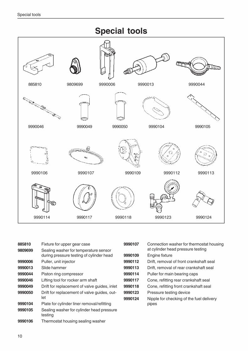
Special tools
10
9990114 9990117 9990118 9990123 9990124
885810 Fixture for upper gear case
9809699 Sealing washer for temperature sensorduring pressure testing of cylinder head
9990006 Puller, unit injector
9990013 Slide hammer
9990044 Piston ring compressor
9990046 Lifting tool for rocker arm shaft
9990049 Drift for replacement of valve guides, inlet
9990050 Drift for replacement of valve guides, out-let
9990104 Plate for cylinder liner removal/refitting
9990105 Sealing washer for cylinder head pressuretesting
9990106 Thermostat housing sealing washer
9990107 Connection washer for thermostat housingat cylinder head pressure testing
9990109 Engine fixture
9990112 Drift, removal of front crankshaft seal
9990113 Drift, removal of rear crankshaft seal
9990114 Puller for main bearing caps
9990117 Cone, refitting rear crankshaft seal
9990118 Cone, refitting front crankshaft seal
9990123 Pressure testing device
9990124 Nipple for checking of the fuel deliverypipes
Special tools
885810 9809699 9990006 9990013 9990044
9990046 9990049 9990050 9990104 9990105
9990106 9990107 9990109 9990112 9990113
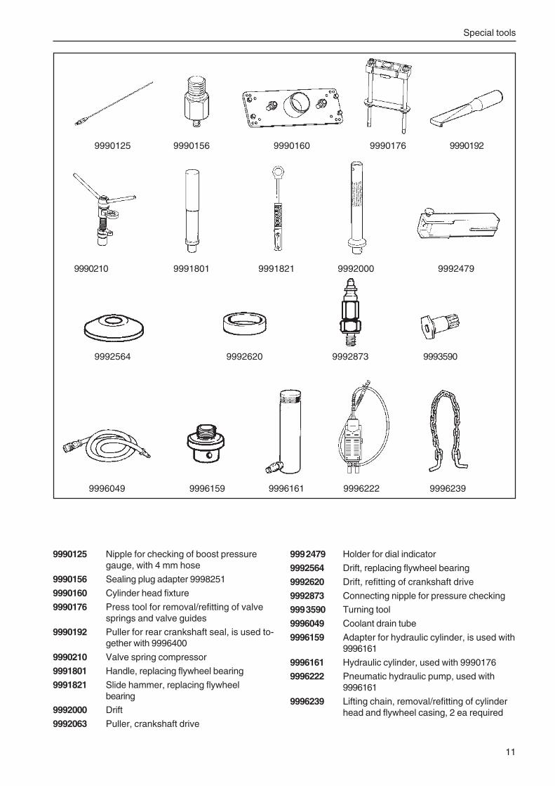
Special tools
11
9990125 9990156 9990160 9990176 9990192
9990210 9991801 9991821 9992000 9992479
9990125 Nipple for checking of boost pressuregauge, with 4 mm hose
9990156 Sealing plug adapter 9998251
9990160 Cylinder head fixture
9990176 Press tool for removal/refitting of valvesprings and valve guides
9990192 Puller for rear crankshaft seal, is used to-gether with 9996400
9990210 Valve spring compressor
9991801 Handle, replacing flywheel bearing
9991821 Slide hammer, replacing flywheelbearing
9992000 Drift
9992063 Puller, crankshaft drive
9992479 Holder for dial indicator
9992564 Drift, replacing flywheel bearing
9992620 Drift, refitting of crankshaft drive
9992873 Connecting nipple for pressure checking
9993590 Turning tool
9996049 Coolant drain tube
9996159 Adapter for hydraulic cylinder, is used with9996161
9996161 Hydraulic cylinder, used with 9990176
9996222 Pneumatic hydraulic pump, used with9996161
9996239 Lifting chain, removal/refitting of cylinderhead and flywheel casing, 2 ea required
9992564 9992620 9992873 9993590
9996049 9996159 9996161 9996222 9996239
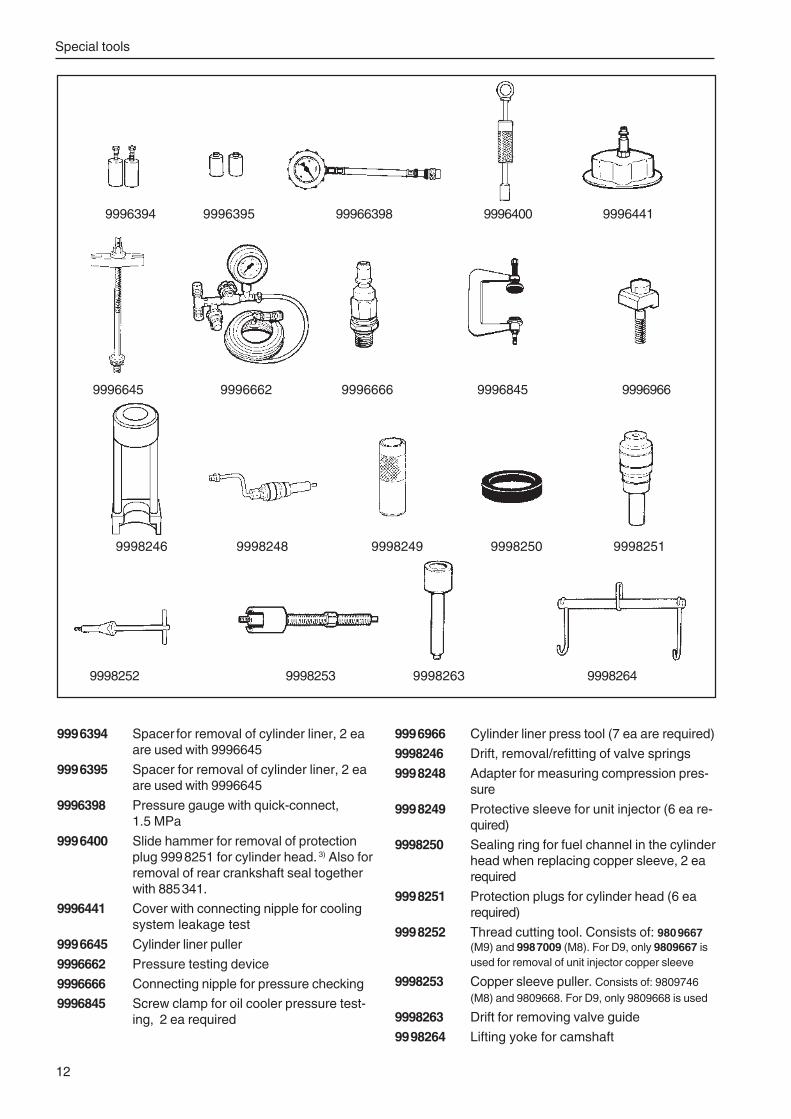
Special tools
12
9996394 Spacer for removal of cylinder liner, 2 eaare used with 9996645
9996395 Spacer for removal of cylinder liner, 2 eaare used with 9996645
9996398 Pressure gauge with quick-connect,1.5 MPa
9996400 Slide hammer for removal of protectionplug 9998251 for cylinder head. 3) Also forremoval of rear crankshaft seal togetherwith 885341.
9996441 Cover with connecting nipple for coolingsystem leakage test
9996645 Cylinder liner puller
9996662 Pressure testing device
9996666 Connecting nipple for pressure checking
9996845 Screw clamp for oil cooler pressure test-ing, 2 ea required
9996966 Cylinder liner press tool (7 ea are required)
9998246 Drift, removal/refitting of valve springs
9998248 Adapter for measuring compression pres-sure
9998249 Protective sleeve for unit injector (6 ea re-quired)
9998250 Sealing ring for fuel channel in the cylinderhead when replacing copper sleeve, 2 earequired
9998251 Protection plugs for cylinder head (6 earequired)
9998252 Thread cutting tool. Consists of: 9809667(M9) and 9987009 (M8). For D9, only 9809667 isused for removal of unit injector copper sleeve
9998253 Copper sleeve puller. Consists of: 9809746(M8) and 9809668. For D9, only 9809668 is used
9998263 Drift for removing valve guide
9998264 Lifting yoke for camshaft
9996394 9996395 99966398 9996400 9996441
9996645 9996662 9996666 9996845 9996966
9998246 9998248 9998249 9998250 9998251
9998252 9998253 9998263 9998264
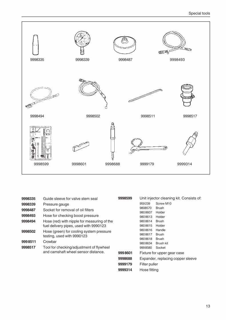
Special tools
13
9998335 Guide sleeve for valve stem seal
9998339 Pressure gauge
9998487 Socket for removal of oil filters
9998493 Hose for checking boost pressure
9998494 Hose (red) with nipple for measuring of thefuel delivery pipes, used with 9990123
9998502 Hose (green) for cooling system pressuretesting, used with 9990123
9998511 Crowbar
9998517 Tool for checking/adjustment of flywheeland camshaft wheel sensor distance.
9998599 Unit injector cleaning kit. Consists of:959239 Screw M109808570 Brush9808607 Holder9808613 Holder9808614 Brush9808615 Holder9808616 Handle9808617 Brush9808618 Brush9808634 Brush kit9998580 Socket
9998601 Fixture for upper gear case
9998688 Expander, replacing copper sleeve
9999179 Filter puller
9999314 Hose fitting
9998335 9998339 9998487 9998493
9998494 9998502 9998511 9998517
9998599 9998601 9998688 9999179 9999314
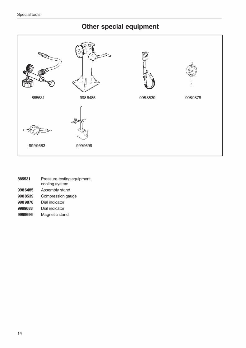
Special tools
14
Other special equipment
885531 Pressure-testing equipment,cooling system
9986485 Assembly stand
9988539 Compression gauge
9989876 Dial indicator
9999683 Dial indicator
9999696 Magnetic stand
885531 9986485 9988539 9989876
9999683 9999696
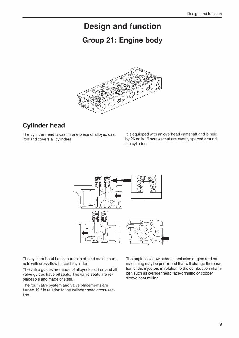
Design and function
15
The cylinder head has separate inlet- and outlet chan-nels with cross-flow for each cylinder.
The valve guides are made of alloyed cast iron and allvalve guides have oil seals. The valve seats are re-placeable and made of steel.
The four valve system and valve placements areturned 12 ° in relation to the cylinder head cross-sec-tion.
Cylinder headThe cylinder head is cast in one piece of alloyed castiron and covers all cylinders
Design and function
Group 21: Engine body
It is equipped with an overhead camshaft and is heldby 26 ea M16 screws that are evenly spaced aroundthe cylinder.
The engine is a low exhaust emission engine and nomachining may be performed that will change the posi-tion of the injectors in relation to the combustion cham-ber, such as cylinder head face-grinding or coppersleeve seat milling.
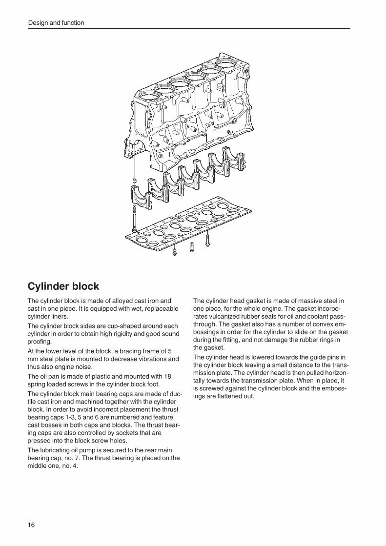
Design and function
16
Cylinder blockThe cylinder block is made of alloyed cast iron andcast in one piece. It is equipped with wet, replaceablecylinder liners.
The cylinder block sides are cup-shaped around eachcylinder in order to obtain high rigidity and good soundproofing.
At the lower level of the block, a bracing frame of 5mm steel plate is mounted to decrease vibrations andthus also engine noise.
The oil pan is made of plastic and mounted with 18spring loaded screws in the cylinder block foot.
The cylinder block main bearing caps are made of duc-tile cast iron and machined together with the cylinderblock. In order to avoid incorrect placement the thrustbearing caps 1-3, 5 and 6 are numbered and featurecast bosses in both caps and blocks. The thrust bear-ing caps are also controlled by sockets that arepressed into the block screw holes.
The lubricating oil pump is secured to the rear mainbearing cap, no. 7. The thrust bearing is placed on themiddle one, no. 4.
The cylinder head gasket is made of massive steel inone piece, for the whole engine. The gasket incorpo-rates vulcanized rubber seals for oil and coolant pass-through. The gasket also has a number of convex em-bossings in order for the cylinder to slide on the gasketduring the fitting, and not damage the rubber rings inthe gasket.
The cylinder head is lowered towards the guide pins inthe cylinder block leaving a small distance to the trans-mission plate. The cylinder head is then pulled horizon-tally towards the transmission plate. When in place, itis screwed against the cylinder block and the emboss-ings are flattened out.
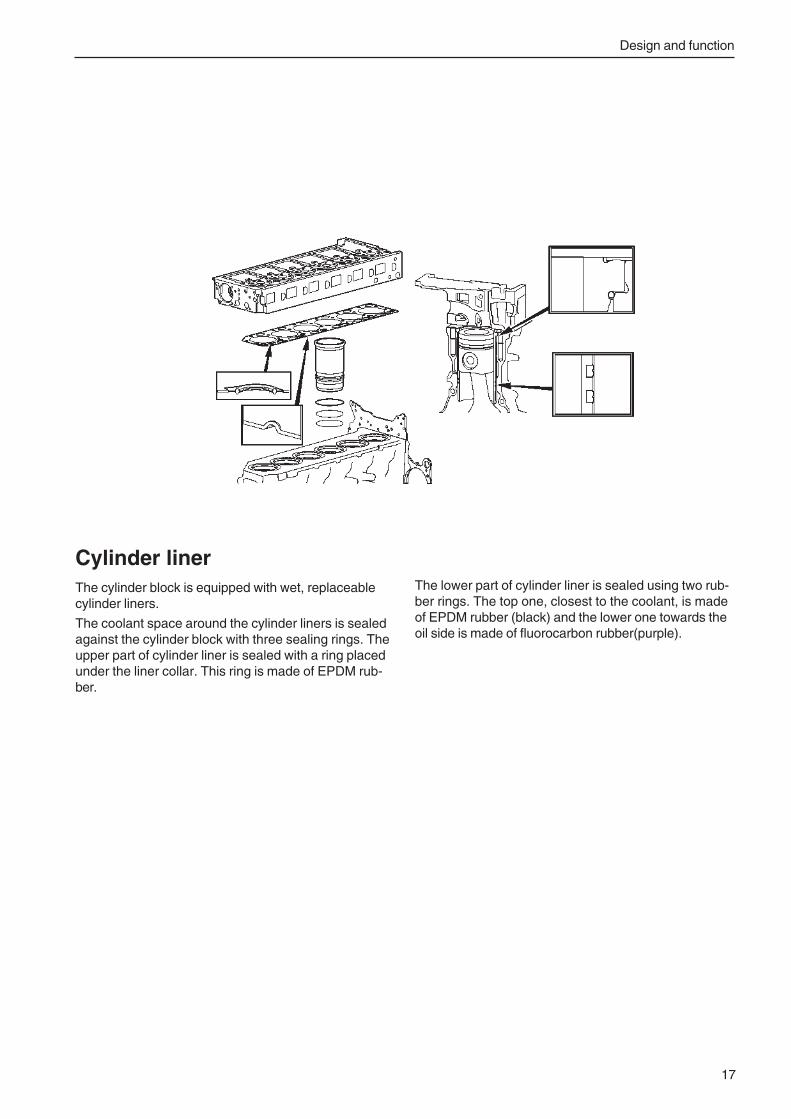
Design and function
17
Cylinder linerThe cylinder block is equipped with wet, replaceablecylinder liners.
The coolant space around the cylinder liners is sealedagainst the cylinder block with three sealing rings. Theupper part of cylinder liner is sealed with a ring placedunder the liner collar. This ring is made of EPDM rub-ber.
The lower part of cylinder liner is sealed using two rub-ber rings. The top one, closest to the coolant, is madeof EPDM rubber (black) and the lower one towards theoil side is made of fluorocarbon rubber(purple).
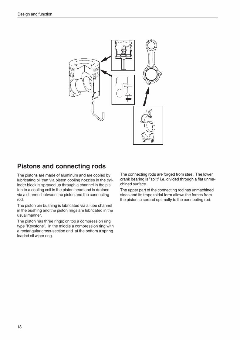
Design and function
18
Pistons and connecting rodsThe pistons are made of aluminum and are cooled bylubricating oil that via piston cooling nozzles in the cyl-inder block is sprayed up through a channel in the pis-ton to a cooling coil in the piston head and is drainedvia a channel between the piston and the connectingrod.
The piston pin bushing is lubricated via a lube channelin the bushing and the piston rings are lubricated in theusual manner.
The piston has three rings; on top a compression ringtype ”Keystone”, in the middle a compression ring witha rectangular cross-section and at the bottom a springloaded oil wiper ring.
The connecting rods are forged from steel. The lowercrank bearing is ”split” i.e. divided through a flat unma-chined surface.
The upper part of the connecting rod has unmachinedsides and its trapezoidal form allows the forces fromthe piston to spread optimally to the connecting rod.
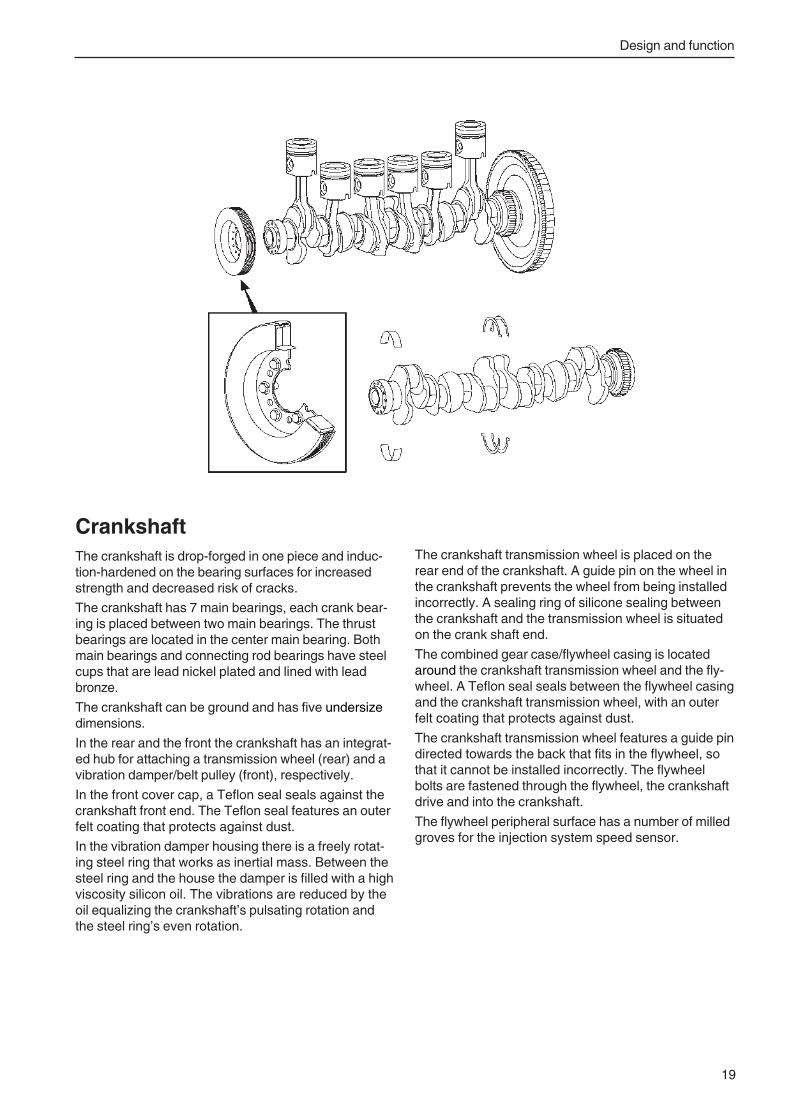
Design and function
19
CrankshaftThe crankshaft is drop-forged in one piece and induc-tion-hardened on the bearing surfaces for increasedstrength and decreased risk of cracks.
The crankshaft has 7 main bearings, each crank bear-ing is placed between two main bearings. The thrustbearings are located in the center main bearing. Bothmain bearings and connecting rod bearings have steelcups that are lead nickel plated and lined with leadbronze.
The crankshaft can be ground and has five undersizedimensions.
In the rear and the front the crankshaft has an integrat-ed hub for attaching a transmission wheel (rear) and avibration damper/belt pulley (front), respectively.
In the front cover cap, a Teflon seal seals against thecrankshaft front end. The Teflon seal features an outerfelt coating that protects against dust.
In the vibration damper housing there is a freely rotat-ing steel ring that works as inertial mass. Between thesteel ring and the house the damper is filled with a highviscosity silicon oil. The vibrations are reduced by theoil equalizing the crankshaft’s pulsating rotation andthe steel ring’s even rotation.
The crankshaft transmission wheel is placed on therear end of the crankshaft. A guide pin on the wheel inthe crankshaft prevents the wheel from being installedincorrectly. A sealing ring of silicone sealing betweenthe crankshaft and the transmission wheel is situatedon the crank shaft end.
The combined gear case/flywheel casing is locatedaround the crankshaft transmission wheel and the fly-wheel. A Teflon seal seals between the flywheel casingand the crankshaft transmission wheel, with an outerfelt coating that protects against dust.
The crankshaft transmission wheel features a guide pindirected towards the back that fits in the flywheel, sothat it cannot be installed incorrectly. The flywheelbolts are fastened through the flywheel, the crankshaftdrive and into the crankshaft.
The flywheel peripheral surface has a number of milledgroves for the injection system speed sensor.
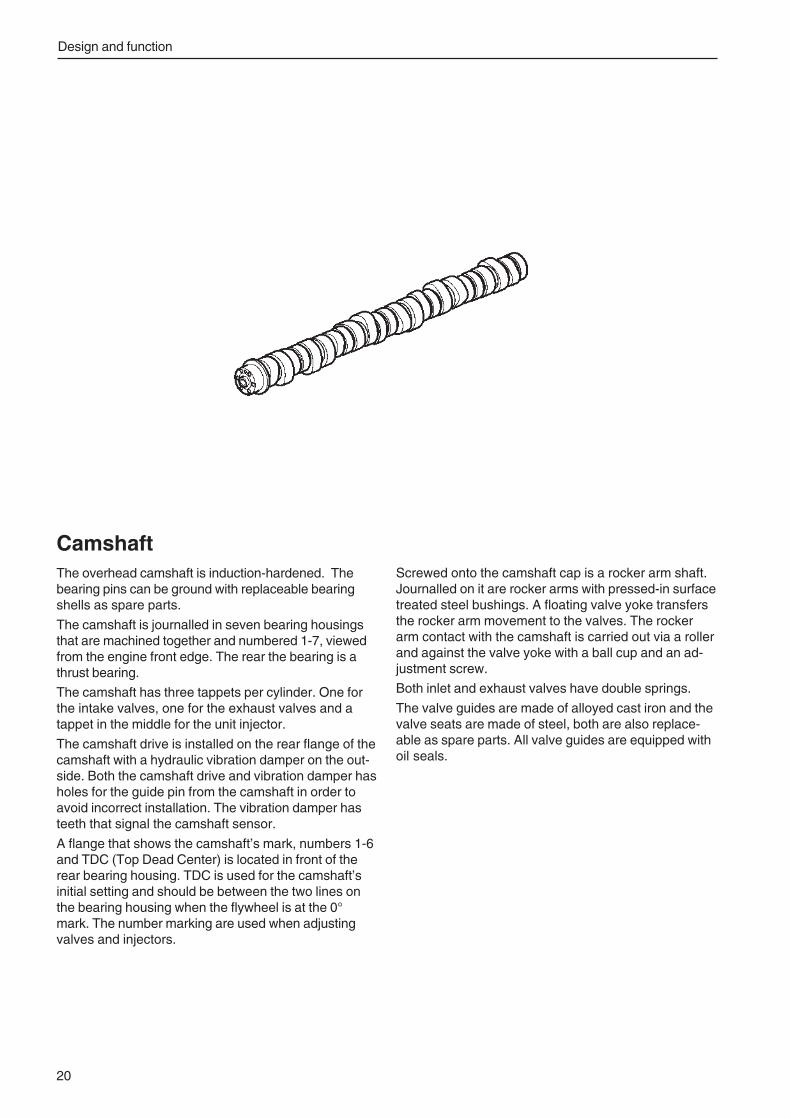
Design and function
20
CamshaftThe overhead camshaft is induction-hardened. Thebearing pins can be ground with replaceable bearingshells as spare parts.
The camshaft is journalled in seven bearing housingsthat are machined together and numbered 1-7, viewedfrom the engine front edge. The rear the bearing is athrust bearing.
The camshaft has three tappets per cylinder. One forthe intake valves, one for the exhaust valves and atappet in the middle for the unit injector.
The camshaft drive is installed on the rear flange of thecamshaft with a hydraulic vibration damper on the out-side. Both the camshaft drive and vibration damper hasholes for the guide pin from the camshaft in order toavoid incorrect installation. The vibration damper hasteeth that signal the camshaft sensor.
A flange that shows the camshaft’s mark, numbers 1-6and TDC (Top Dead Center) is located in front of therear bearing housing. TDC is used for the camshaft’sinitial setting and should be between the two lines onthe bearing housing when the flywheel is at the 0°mark. The number marking are used when adjustingvalves and injectors.
Screwed onto the camshaft cap is a rocker arm shaft.Journalled on it are rocker arms with pressed-in surfacetreated steel bushings. A floating valve yoke transfersthe rocker arm movement to the valves. The rockerarm contact with the camshaft is carried out via a rollerand against the valve yoke with a ball cup and an ad-justment screw.
Both inlet and exhaust valves have double springs.
The valve guides are made of alloyed cast iron and thevalve seats are made of steel, both are also replace-able as spare parts. All valve guides are equipped withoil seals.
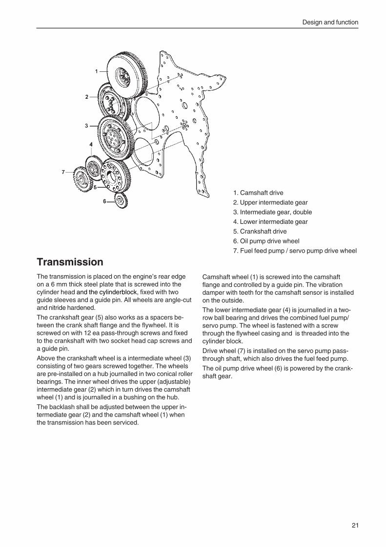
Design and function
21
TransmissionThe transmission is placed on the engine’s rear edgeon a 6 mm thick steel plate that is screwed into thecylinder head and the cylinderblock, fixed with twoguide sleeves and a guide pin. All wheels are angle-cutand nitride hardened.
The crankshaft gear (5) also works as a spacers be-tween the crank shaft flange and the flywheel. It isscrewed on with 12 ea pass-through screws and fixedto the crankshaft with two socket head cap screws anda guide pin.
Above the crankshaft wheel is a intermediate wheel (3)consisting of two gears screwed together. The wheelsare pre-installed on a hub journalled in two conical rollerbearings. The inner wheel drives the upper (adjustable)intermediate gear (2) which in turn drives the camshaftwheel (1) and is journalled in a bushing on the hub.
The backlash shall be adjusted between the upper in-termediate gear (2) and the camshaft wheel (1) whenthe transmission has been serviced.
1. Camshaft drive
2. Upper intermediate gear
3. Intermediate gear, double
4. Lower intermediate gear
5. Crankshaft drive
6. Oil pump drive wheel
7. Fuel feed pump / servo pump drive wheel
Camshaft wheel (1) is screwed into the camshaftflange and controlled by a guide pin. The vibrationdamper with teeth for the camshaft sensor is installedon the outside.
The lower intermediate gear (4) is journalled in a two-row ball bearing and drives the combined fuel pump/servo pump. The wheel is fastened with a screwthrough the flywheel casing and is threaded into thecylinder block.
Drive wheel (7) is installed on the servo pump pass-through shaft, which also drives the fuel feed pump.
The oil pump drive wheel (6) is powered by the crank-shaft gear.
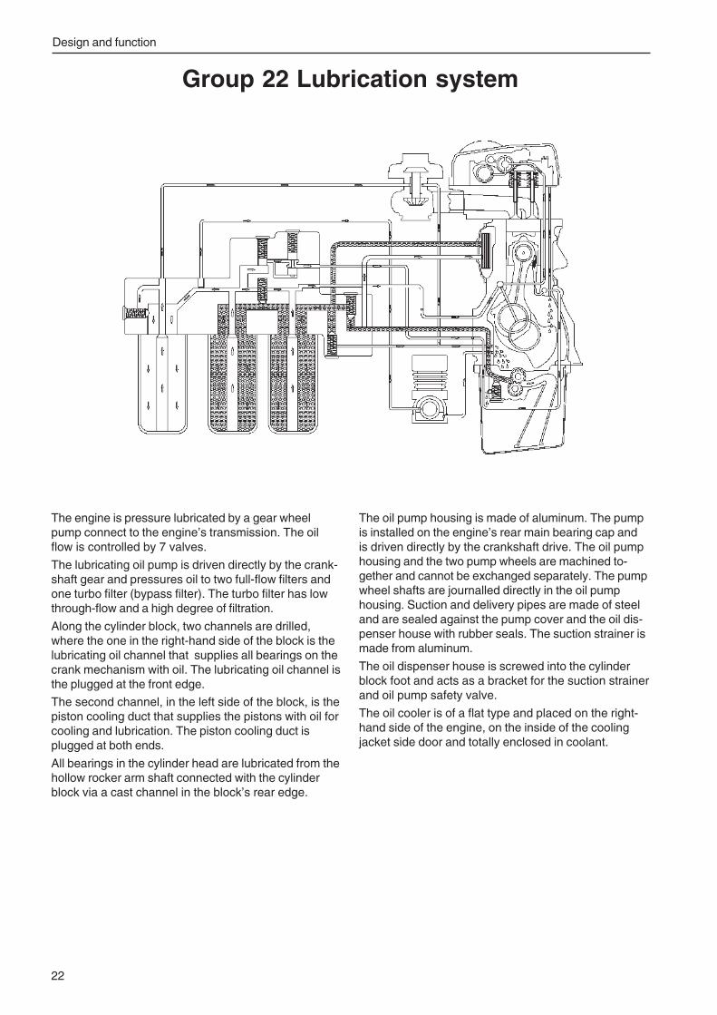
Design and function
22
Group 22 Lubrication system
The engine is pressure lubricated by a gear wheelpump connect to the engine’s transmission. The oilflow is controlled by 7 valves.
The lubricating oil pump is driven directly by the crank-shaft gear and pressures oil to two full-flow filters andone turbo filter (bypass filter). The turbo filter has lowthrough-flow and a high degree of filtration.
Along the cylinder block, two channels are drilled,where the one in the right-hand side of the block is thelubricating oil channel that supplies all bearings on thecrank mechanism with oil. The lubricating oil channel isthe plugged at the front edge.
The second channel, in the left side of the block, is thepiston cooling duct that supplies the pistons with oil forcooling and lubrication. The piston cooling duct isplugged at both ends.
All bearings in the cylinder head are lubricated from thehollow rocker arm shaft connected with the cylinderblock via a cast channel in the block’s rear edge.
The oil pump housing is made of aluminum. The pumpis installed on the engine’s rear main bearing cap andis driven directly by the crankshaft drive. The oil pumphousing and the two pump wheels are machined to-gether and cannot be exchanged separately. The pumpwheel shafts are journalled directly in the oil pumphousing. Suction and delivery pipes are made of steeland are sealed against the pump cover and the oil dis-penser house with rubber seals. The suction strainer ismade from aluminum.
The oil dispenser house is screwed into the cylinderblock foot and acts as a bracket for the suction strainerand oil pump safety valve.
The oil cooler is of a flat type and placed on the right-hand side of the engine, on the inside of the coolingjacket side door and totally enclosed in coolant.
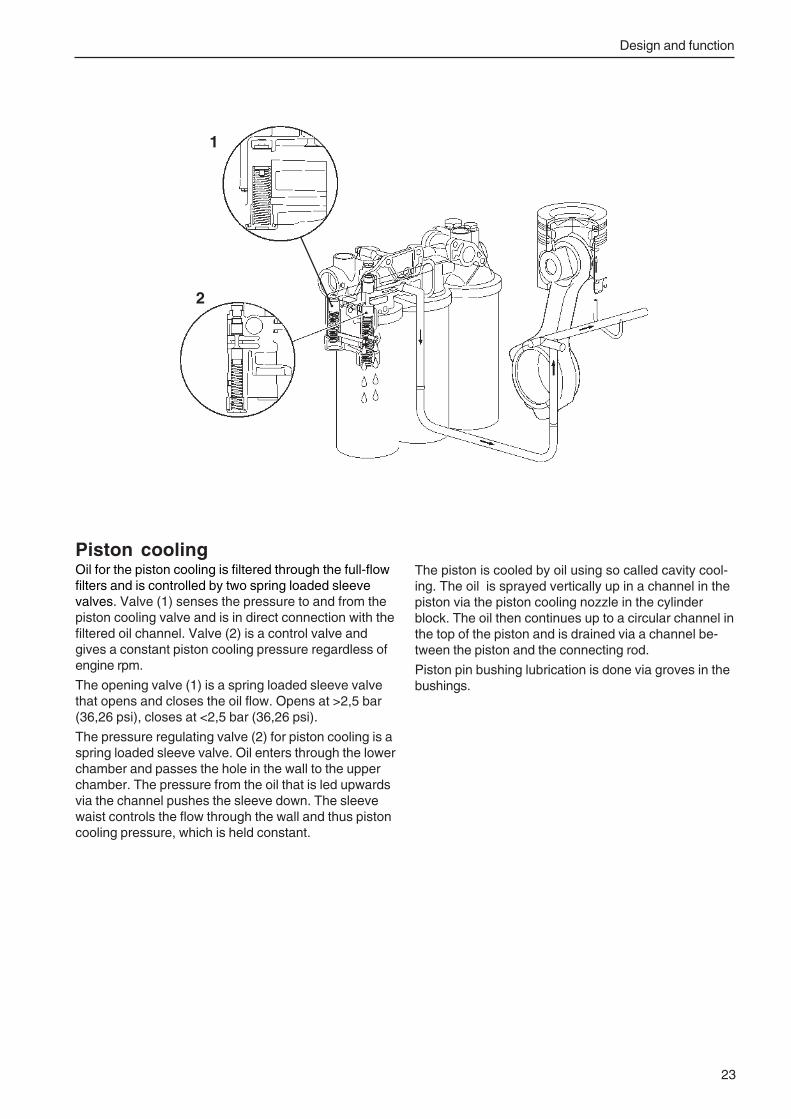
Design and function
23
Piston coolingOil for the piston cooling is filtered through the full-flowfilters and is controlled by two spring loaded sleevevalves. Valve (1) senses the pressure to and from thepiston cooling valve and is in direct connection with thefiltered oil channel. Valve (2) is a control valve andgives a constant piston cooling pressure regardless ofengine rpm.
The opening valve (1) is a spring loaded sleeve valvethat opens and closes the oil flow. Opens at >2,5 bar(36,26 psi), closes at <2,5 bar (36,26 psi).
The pressure regulating valve (2) for piston cooling is aspring loaded sleeve valve. Oil enters through the lowerchamber and passes the hole in the wall to the upperchamber. The pressure from the oil that is led upwardsvia the channel pushes the sleeve down. The sleevewaist controls the flow through the wall and thus pistoncooling pressure, which is held constant.
The piston is cooled by oil using so called cavity cool-ing. The oil is sprayed vertically up in a channel in thepiston via the piston cooling nozzle in the cylinderblock. The oil then continues up to a circular channel inthe top of the piston and is drained via a channel be-tween the piston and the connecting rod.
Piston pin bushing lubrication is done via groves in thebushings.
1
2
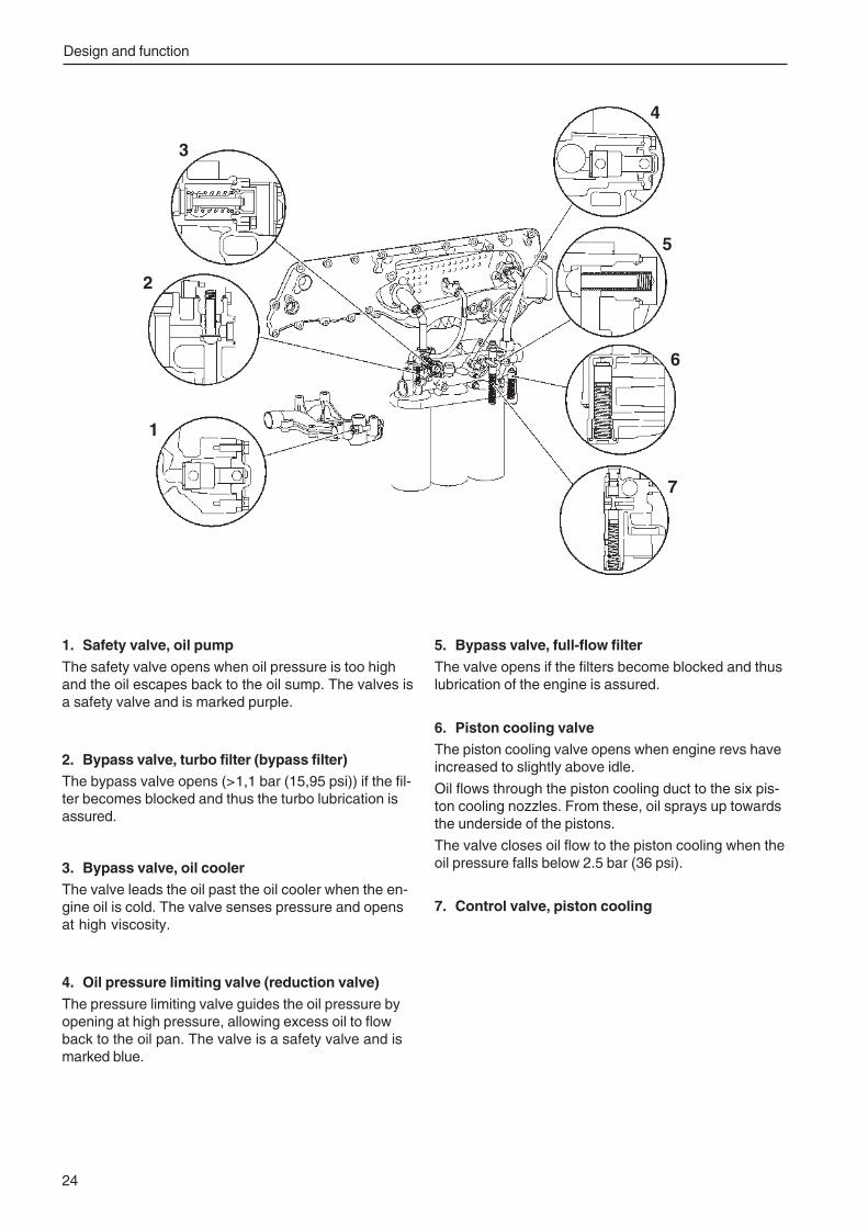
Design and function
24
1. Safety valve, oil pump
The safety valve opens when oil pressure is too highand the oil escapes back to the oil sump. The valves isa safety valve and is marked purple.
2. Bypass valve, turbo filter (bypass filter)The bypass valve opens (>1,1 bar (15,95 psi)) if the fil-ter becomes blocked and thus the turbo lubrication isassured.
3. Bypass valve, oil coolerThe valve leads the oil past the oil cooler when the en-gine oil is cold. The valve senses pressure and opensat high viscosity.
4. Oil pressure limiting valve (reduction valve)
The pressure limiting valve guides the oil pressure byopening at high pressure, allowing excess oil to flowback to the oil pan. The valve is a safety valve and ismarked blue.
5. Bypass valve, full-flow filter
The valve opens if the filters become blocked and thuslubrication of the engine is assured.
6. Piston cooling valveThe piston cooling valve opens when engine revs haveincreased to slightly above idle.
Oil flows through the piston cooling duct to the six pis-ton cooling nozzles. From these, oil sprays up towardsthe underside of the pistons.
The valve closes oil flow to the piston cooling when theoil pressure falls below 2.5 bar (36 psi).
7. Control valve, piston cooling
1
2
3
4
5
6
7
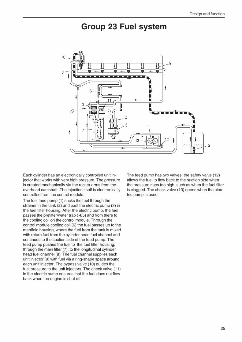
Design and function
25
Each cylinder has an electronically controlled unit in-jector that works with very high pressure. The pressureis created mechanically via the rocker arms from theoverhead camshaft. The injection itself is electronicallycontrolled from the control module.
The fuel feed pump (1) sucks the fuel through thestrainer in the tank (2) and past the electric pump (3) inthe fuel filter housing. After the electric pump, the fuelpasses the prefilter/water trap ( 4/5) and from there tothe cooling coil on the control module. Through thecontrol module cooling coil (6) the fuel passes up to themanifold housing, where the fuel from the tank is mixedwith return fuel from the cylinder head fuel channel andcontinues to the suction side of the feed pump. Thefeed pump pushes the fuel to the fuel filter housing,through the main filter (7), to the longitudinal cylinderhead fuel channel (8). The fuel channel supplies eachunit injector (9) with fuel via a ring-shape space aroundeach unit injector. The bypass valve (10) guides thefuel pressure to the unit injectors. The check valve (11)in the electric pump ensures that the fuel does not flowback when the engine is shut off.
Group 23 Fuel system
The feed pump has two valves; the safety valve (12)allows the fuel to flow back to the suction side whenthe pressure rises too high, such as when the fuel filteris clogged. The check valve (13) opens when the elec-tric pump is used.
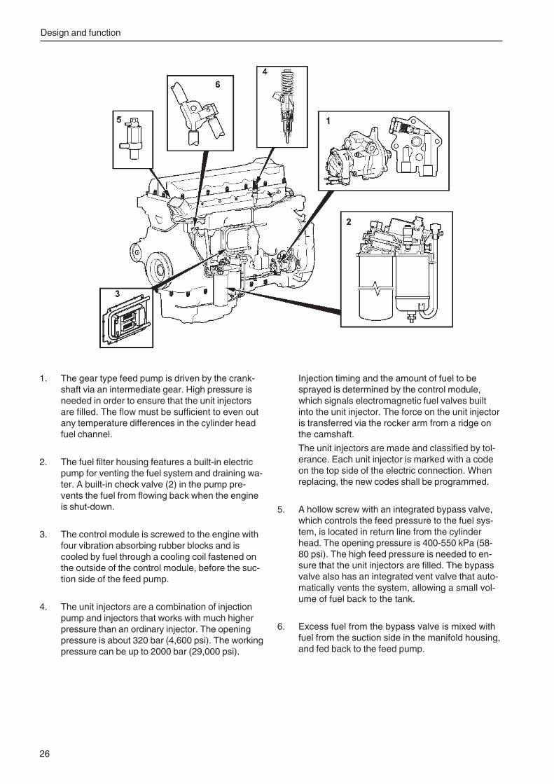
Design and function
26
1. The gear type feed pump is driven by the crank-shaft via an intermediate gear. High pressure isneeded in order to ensure that the unit injectorsare filled. The flow must be sufficient to even outany temperature differences in the cylinder headfuel channel.
2. The fuel filter housing features a built-in electricpump for venting the fuel system and draining wa-ter. A built-in check valve (2) in the pump pre-vents the fuel from flowing back when the engineis shut-down.
3. The control module is screwed to the engine withfour vibration absorbing rubber blocks and iscooled by fuel through a cooling coil fastened onthe outside of the control module, before the suc-tion side of the feed pump.
4. The unit injectors are a combination of injectionpump and injectors that works with much higherpressure than an ordinary injector. The openingpressure is about 320 bar (4,600 psi). The workingpressure can be up to 2000 bar (29,000 psi).
Injection timing and the amount of fuel to besprayed is determined by the control module,which signals electromagnetic fuel valves builtinto the unit injector. The force on the unit injectoris transferred via the rocker arm from a ridge onthe camshaft.
The unit injectors are made and classified by tol-erance. Each unit injector is marked with a codeon the top side of the electric connection. Whenreplacing, the new codes shall be programmed.
5. A hollow screw with an integrated bypass valve,which controls the feed pressure to the fuel sys-tem, is located in return line from the cylinderhead. The opening pressure is 400-550 kPa (58-80 psi). The high feed pressure is needed to en-sure that the unit injectors are filled. The bypassvalve also has an integrated vent valve that auto-matically vents the system, allowing a small vol-ume of fuel back to the tank.
6. Excess fuel from the bypass valve is mixed withfuel from the suction side in the manifold housing,and fed back to the feed pump.
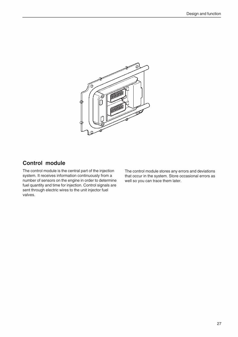
Design and function
27
Control moduleThe control module is the central part of the injectionsystem. It receives information continuously from anumber of sensors on the engine in order to determinefuel quantity and time for injection. Control signals aresent through electric wires to the unit injector fuelvalves.
The control module stores any errors and deviationsthat occur in the system. Store occasional errors aswell so you can trace them later.
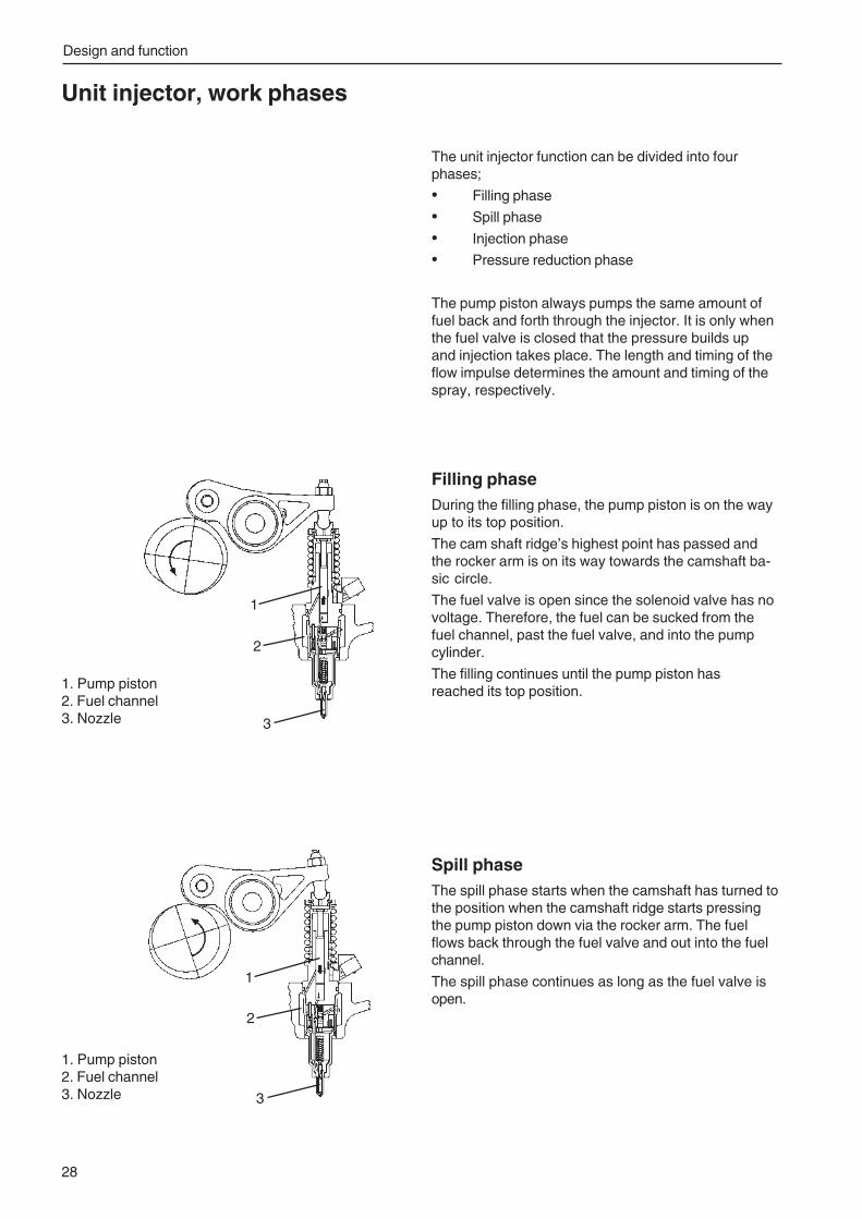
Design and function
28
Spill phaseThe spill phase starts when the camshaft has turned tothe position when the camshaft ridge starts pressingthe pump piston down via the rocker arm. The fuelflows back through the fuel valve and out into the fuelchannel.
The spill phase continues as long as the fuel valve isopen.
Unit injector, work phases
The unit injector function can be divided into fourphases;
• Filling phase
• Spill phase
• Injection phase
• Pressure reduction phase
The pump piston always pumps the same amount offuel back and forth through the injector. It is only whenthe fuel valve is closed that the pressure builds upand injection takes place. The length and timing of theflow impulse determines the amount and timing of thespray, respectively.
Filling phaseDuring the filling phase, the pump piston is on the wayup to its top position.
The cam shaft ridge’s highest point has passed andthe rocker arm is on its way towards the camshaft ba-sic circle.
The fuel valve is open since the solenoid valve has novoltage. Therefore, the fuel can be sucked from thefuel channel, past the fuel valve, and into the pumpcylinder.
The filling continues until the pump piston hasreached its top position.
1
2
3
1. Pump piston2. Fuel channel3. Nozzle
1
2
3
1. Pump piston2. Fuel channel3. Nozzle
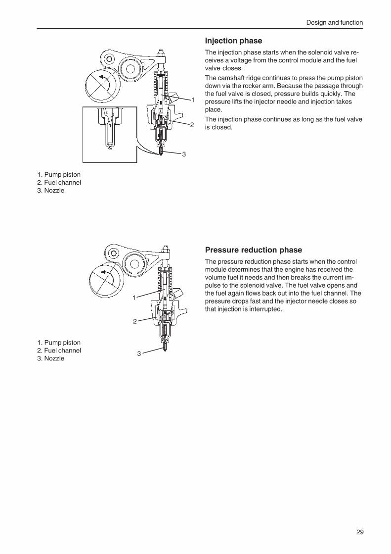
Design and function
29
Injection phaseThe injection phase starts when the solenoid valve re-ceives a voltage from the control module and the fuelvalve closes.
The camshaft ridge continues to press the pump pistondown via the rocker arm. Because the passage throughthe fuel valve is closed, pressure builds quickly. Thepressure lifts the injector needle and injection takesplace.
The injection phase continues as long as the fuel valveis closed.
Pressure reduction phaseThe pressure reduction phase starts when the controlmodule determines that the engine has received thevolume fuel it needs and then breaks the current im-pulse to the solenoid valve. The fuel valve opens andthe fuel again flows back out into the fuel channel. Thepressure drops fast and the injector needle closes sothat injection is interrupted.
1. Pump piston2. Fuel channel3. Nozzle
1
2
3
1. Pump piston2. Fuel channel3. Nozzle
3
1
2
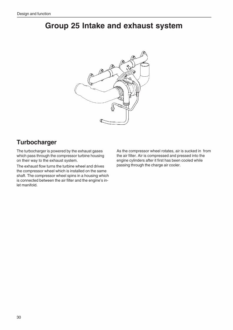
Design and function
30
Group 25 Intake and exhaust system
TurbochargerThe turbocharger is powered by the exhaust gaseswhich pass through the compressor turbine housingon their way to the exhaust system.
The exhaust flow turns the turbine wheel and drivesthe compressor wheel which is installed on the sameshaft. The compressor wheel spins in a housing whichis connected between the air filter and the engine’s in-let manifold.
As the compressor wheel rotates, air is sucked in fromthe air filter. Air is compressed and pressed into theengine cylinders after it first has been cooled whilepassing through the charge air cooler.
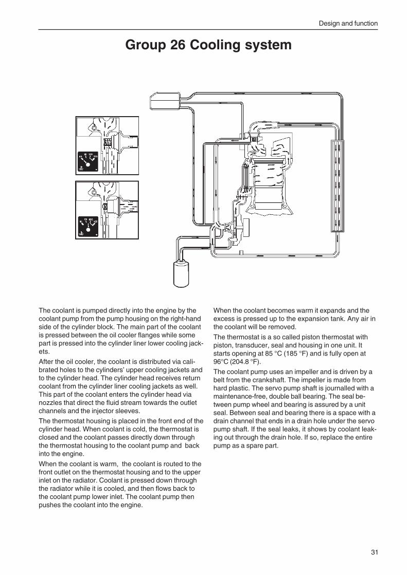
Design and function
31
The coolant is pumped directly into the engine by thecoolant pump from the pump housing on the right-handside of the cylinder block. The main part of the coolantis pressed between the oil cooler flanges while somepart is pressed into the cylinder liner lower cooling jack-ets.
After the oil cooler, the coolant is distributed via cali-brated holes to the cylinders’ upper cooling jackets andto the cylinder head. The cylinder head receives returncoolant from the cylinder liner cooling jackets as well.This part of the coolant enters the cylinder head vianozzles that direct the fluid stream towards the outletchannels and the injector sleeves.
The thermostat housing is placed in the front end of thecylinder head. When coolant is cold, the thermostat isclosed and the coolant passes directly down throughthe thermostat housing to the coolant pump and backinto the engine.
When the coolant is warm, the coolant is routed to thefront outlet on the thermostat housing and to the upperinlet on the radiator. Coolant is pressed down throughthe radiator while it is cooled, and then flows back tothe coolant pump lower inlet. The coolant pump thenpushes the coolant into the engine.
Group 26 Cooling system
When the coolant becomes warm it expands and theexcess is pressed up to the expansion tank. Any air inthe coolant will be removed.
The thermostat is a so called piston thermostat withpiston, transducer, seal and housing in one unit. Itstarts opening at 85 °C (185 °F) and is fully open at96°C (204.8 °F).
The coolant pump uses an impeller and is driven by abelt from the crankshaft. The impeller is made fromhard plastic. The servo pump shaft is journalled with amaintenance-free, double ball bearing. The seal be-tween pump wheel and bearing is assured by a unitseal. Between seal and bearing there is a space with adrain channel that ends in a drain hole under the servopump shaft. If the seal leaks, it shows by coolant leak-ing out through the drain hole. If so, replace the entirepump as a spare part.
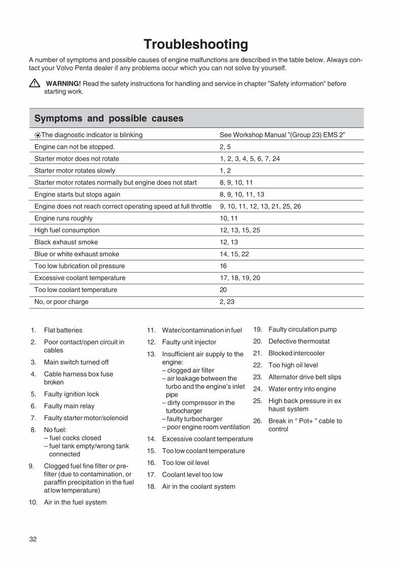
32
TroubleshootingA number of symptoms and possible causes of engine malfunctions are described in the table below. Always con-tact your Volvo Penta dealer if any problems occur which you can not solve by yourself.
WARNING! Read the safety instructions for handling and service in chapter ”Safety information” beforestarting work.
Symptoms and possible causes
The diagnostic indicator is blinking See Workshop Manual ”(Group 23) EMS 2”
Engine can not be stopped. 2, 5
Starter motor does not rotate 1, 2, 3, 4, 5, 6, 7, 24
Starter motor rotates slowly 1, 2
Starter motor rotates normally but engine does not start 8, 9, 10, 11
Engine starts but stops again 8, 9, 10, 11, 13
Engine does not reach correct operating speed at full throttle 9, 10, 11, 12, 13, 21, 25, 26
Engine runs roughly 10, 11
High fuel consumption 12, 13, 15, 25
Black exhaust smoke 12, 13
Blue or white exhaust smoke 14, 15, 22
Too low lubrication oil pressure 16
Excessive coolant temperature 17, 18, 19, 20
Too low coolant temperature 20
No, or poor charge 2, 23
1. Flat batteries
2. Poor contact/open circuit incables
3. Main switch turned off
4. Cable harness box fusebroken
5. Faulty ignition lock
6. Faulty main relay
7. Faulty starter motor/solenoid
8. No fuel:– fuel cocks closed– fuel tank empty/wrong tank
connected
9. Clogged fuel fine filter or pre-filter (due to contamination, orparaffin precipitation in the fuelat low temperature)
10. Air in the fuel system
11. Water/contamination in fuel
12. Faulty unit injector
13. Insufficient air supply to theengine:– clogged air filter– air leakage between the
turbo and the engine’s inletpipe
– dirty compressor in theturbocharger
– faulty turbocharger– poor engine room ventilation
14. Excessive coolant temperature
15. Too low coolant temperature
16. Too low oil level
17. Coolant level too low
18. Air in the coolant system
19. Faulty circulation pump
20. Defective thermostat
21. Blocked intercooler
22. Too high oil level
23. Alternator drive belt slips
24. Water entry into engine
25. High back pressure in exhaust system
26. Break in “ Pot+ ” cable tocontrol
Troubleshooting / Tests and adjustments
33
Operational disturbancesFor additional information and more troubleshootinghelp, see “Coolant temperature, troubleshooting”. Incase of an operational disturbance, check the followingpoints first:
• Check that the coolant level is within markings onthe expansion tank (at about 20 °C (68 °F)). If thelevel is too low in the expansion tank, add coolantand start the engine. If the coolant disappears,there is internal or external leakage.
• Check that the coolant is not contaminated. If thecoolant is contaminated, this signifies internalleakage (oil) or that the cooling system has block-age (deposits). A clogged cooling system iscaused by one or more of the following factors:
• Coolant change has not been done as scheduled.
• Incorrect mix of coolant and water.
• Contaminated water has been used.
CloggingHigh coolant temperature is most often due to internalor external clogging of the cooling system or a combi-nation of both. If the cooling system is clogged, it mustbe cleaned. See “Radiator, outside cleaning” and “Cool-ing system, flushing”
• External dirt: Check that the cooler and/or thecharge air cooler are not clogged.
Check for external or internal leakage in the cool-ing system.
• Inner contamination: Check that the cooler and/or the charge air cooler are not clogged. If youcannot see the light through at least one third, thecooler should be removed and cleaned.
• External and internal leakage in the coolingsystem: Check for leakage in the system.
• Coolant circulation: Check that the coolant cir-culates by allowing the engine to run at a highrpm. Check that the coolant circulates in the ex-pansion tank too. This may be a clue if there issomething wrong with the cooling system.
• Thermostat: Check the thermostat function. Drainenough coolant that the thermostat can be re-moved. Check the thermostat, see “Thermostat,testing”
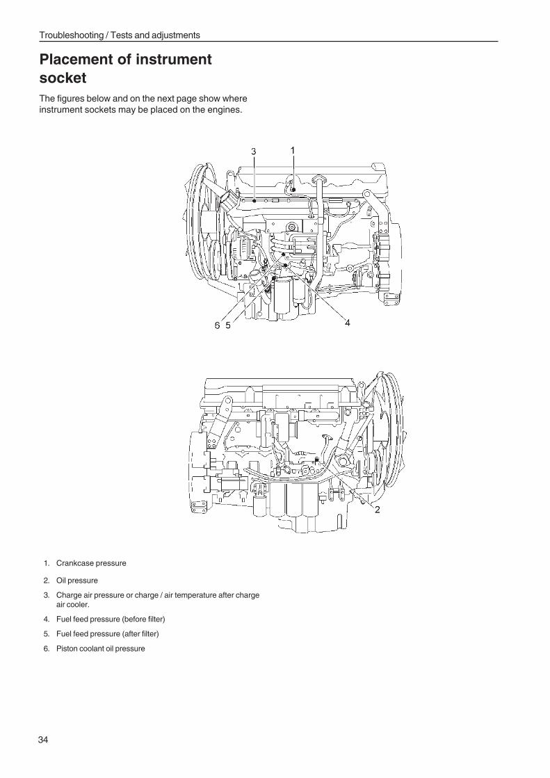
Troubleshooting / Tests and adjustments
34
Placement of instrumentsocketThe figures below and on the next page show whereinstrument sockets may be placed on the engines.
1. Crankcase pressure
2. Oil pressure
3. Charge air pressure or charge / air temperature after chargeair cooler.
4. Fuel feed pressure (before filter)
5. Fuel feed pressure (after filter)
6. Piston coolant oil pressure
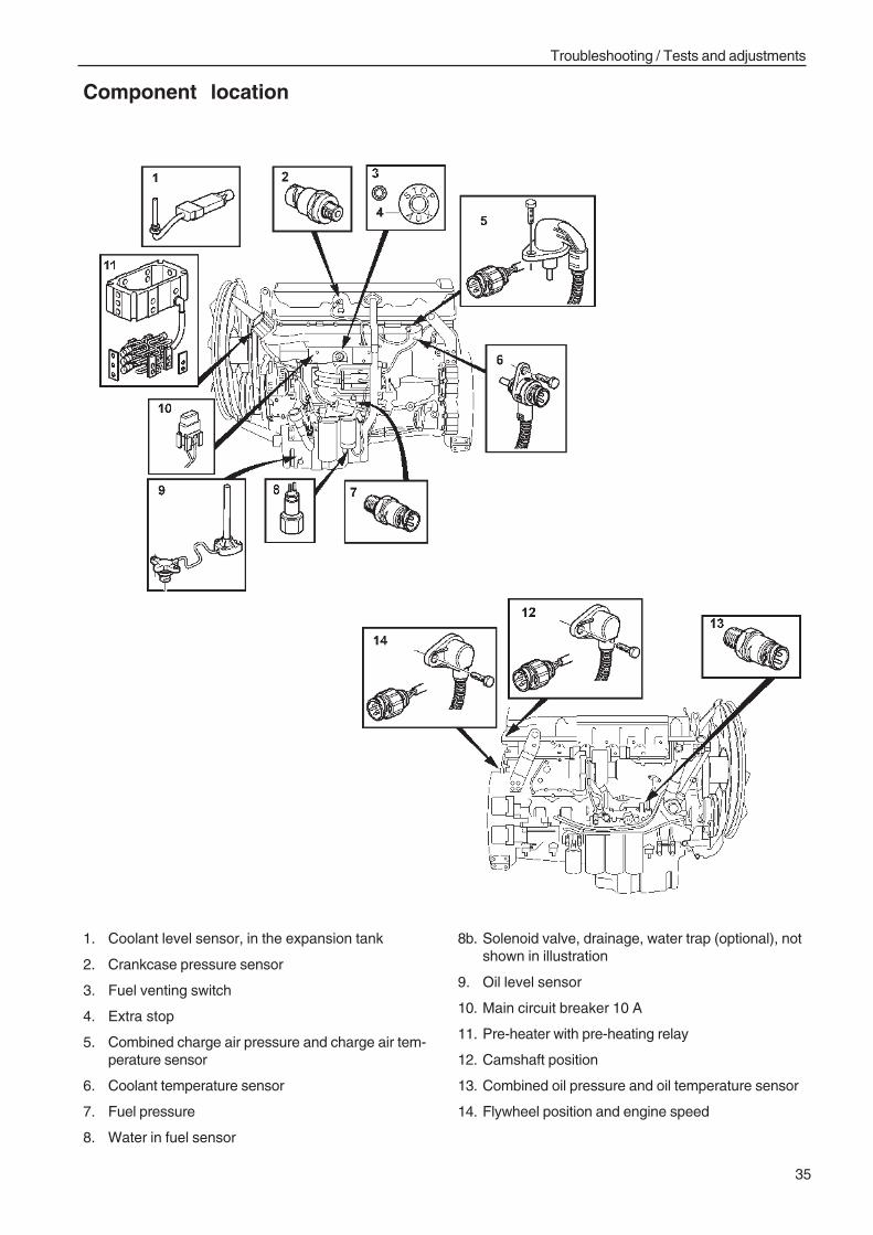
Troubleshooting / Tests and adjustments
35
Component location
1. Coolant level sensor, in the expansion tank
2. Crankcase pressure sensor
3. Fuel venting switch
4. Extra stop
5. Combined charge air pressure and charge air tem-perature sensor
6. Coolant temperature sensor
7. Fuel pressure
8. Water in fuel sensor
8b. Solenoid valve, drainage, water trap (optional), notshown in illustration
9. Oil level sensor
10. Main circuit breaker 10 A
11. Pre-heater with pre-heating relay
12. Camshaft position
13. Combined oil pressure and oil temperature sensor
14. Flywheel position and engine speed
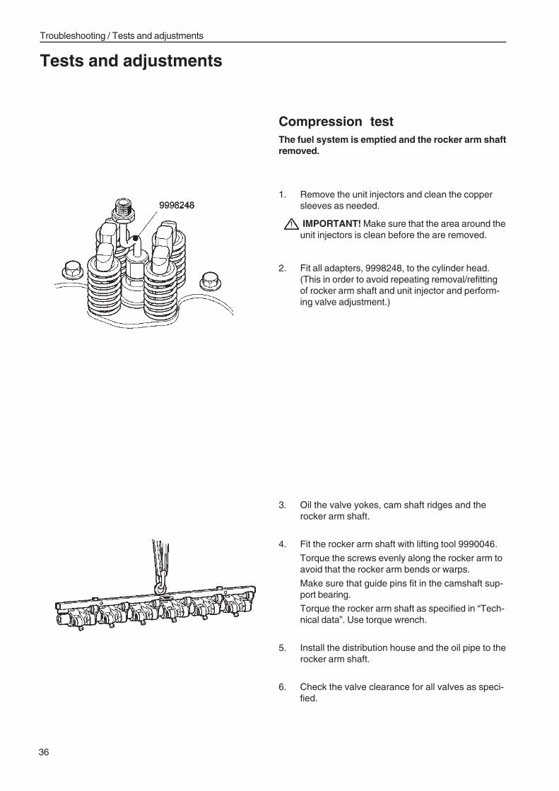
Troubleshooting / Tests and adjustments
36
Compression testThe fuel system is emptied and the rocker arm shaftremoved.
1. Remove the unit injectors and clean the coppersleeves as needed.
IMPORTANT! Make sure that the area around theunit injectors is clean before the are removed.
2. Fit all adapters, 9998248, to the cylinder head.(This in order to avoid repeating removal/refittingof rocker arm shaft and unit injector and perform-ing valve adjustment.)
3. Oil the valve yokes, cam shaft ridges and therocker arm shaft.
4. Fit the rocker arm shaft with lifting tool 9990046.
Torque the screws evenly along the rocker arm toavoid that the rocker arm bends or warps.
Make sure that guide pins fit in the camshaft sup-port bearing.
Torque the rocker arm shaft as specified in “Tech-nical data”. Use torque wrench.
5. Install the distribution house and the oil pipe to therocker arm shaft.
6. Check the valve clearance for all valves as speci-fied.
Tests and adjustments
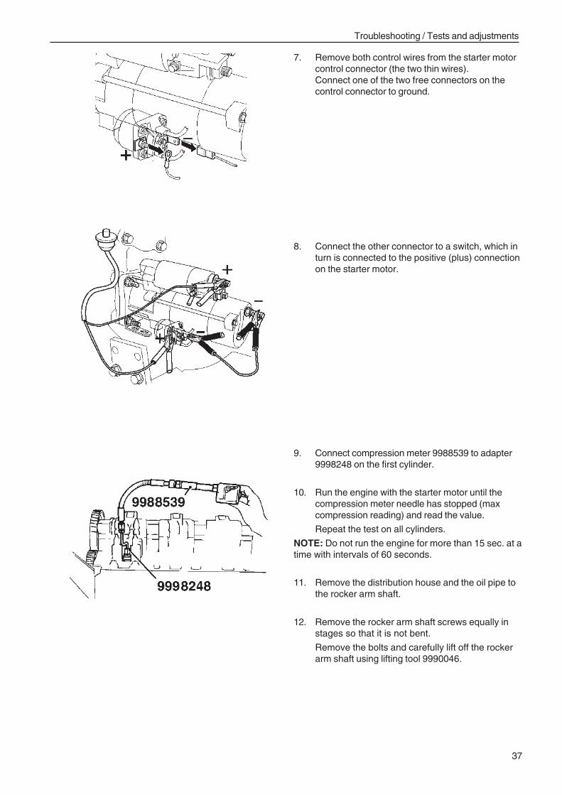
Troubleshooting / Tests and adjustments
37
7. Remove both control wires from the starter motorcontrol connector (the two thin wires).Connect one of the two free connectors on thecontrol connector to ground.
8. Connect the other connector to a switch, which inturn is connected to the positive (plus) connectionon the starter motor.
9. Connect compression meter 9988539 to adapter9998248 on the first cylinder.
10. Run the engine with the starter motor until thecompression meter needle has stopped (maxcompression reading) and read the value.
Repeat the test on all cylinders.
NOTE: Do not run the engine for more than 15 sec. at atime with intervals of 60 seconds.
11. Remove the distribution house and the oil pipe tothe rocker arm shaft.
12. Remove the rocker arm shaft screws equally instages so that it is not bent.
Remove the bolts and carefully lift off the rockerarm shaft using lifting tool 9990046.
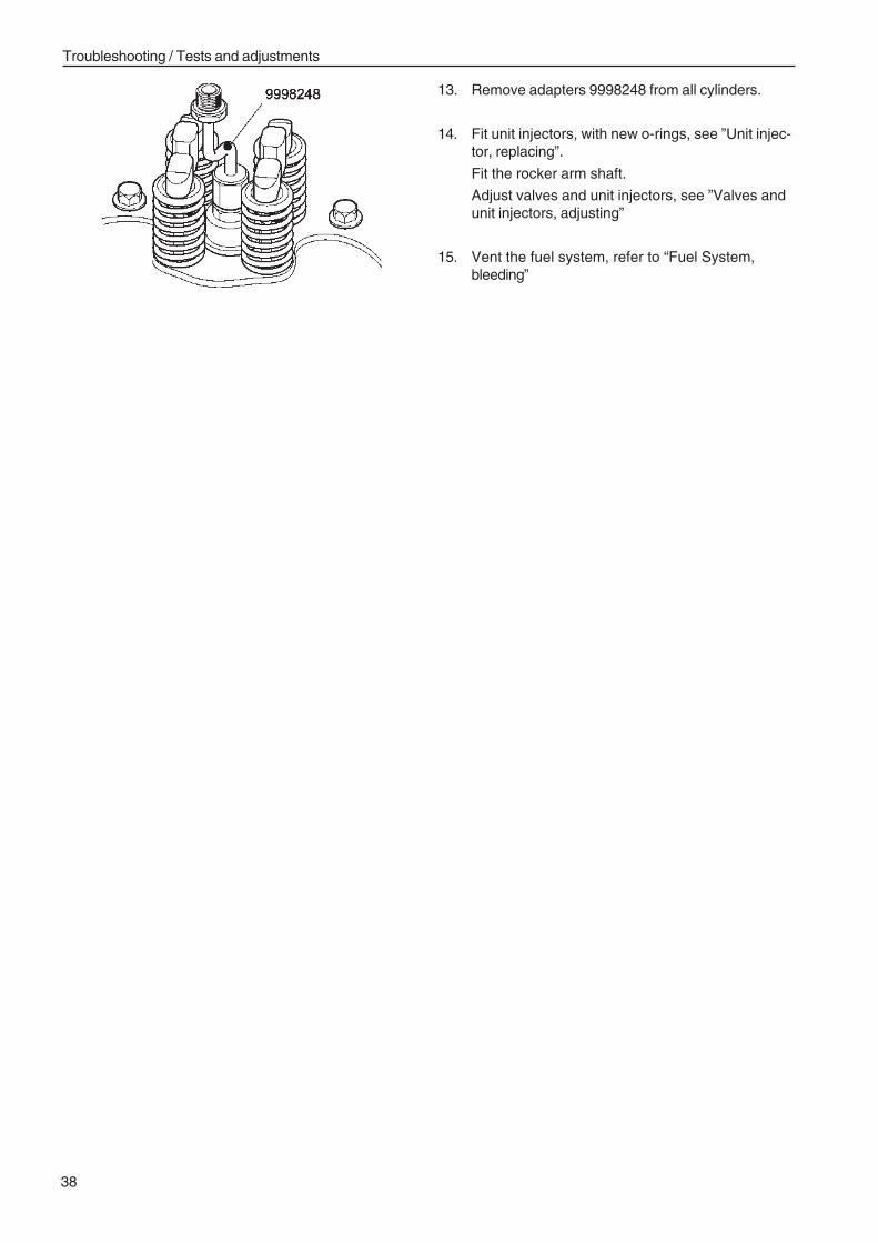
Troubleshooting / Tests and adjustments
38
13. Remove adapters 9998248 from all cylinders.
14. Fit unit injectors, with new o-rings, see ”Unit injec-tor, replacing”.
Fit the rocker arm shaft.
Adjust valves and unit injectors, see ”Valves andunit injectors, adjusting”
15. Vent the fuel system, refer to “Fuel System,bleeding”
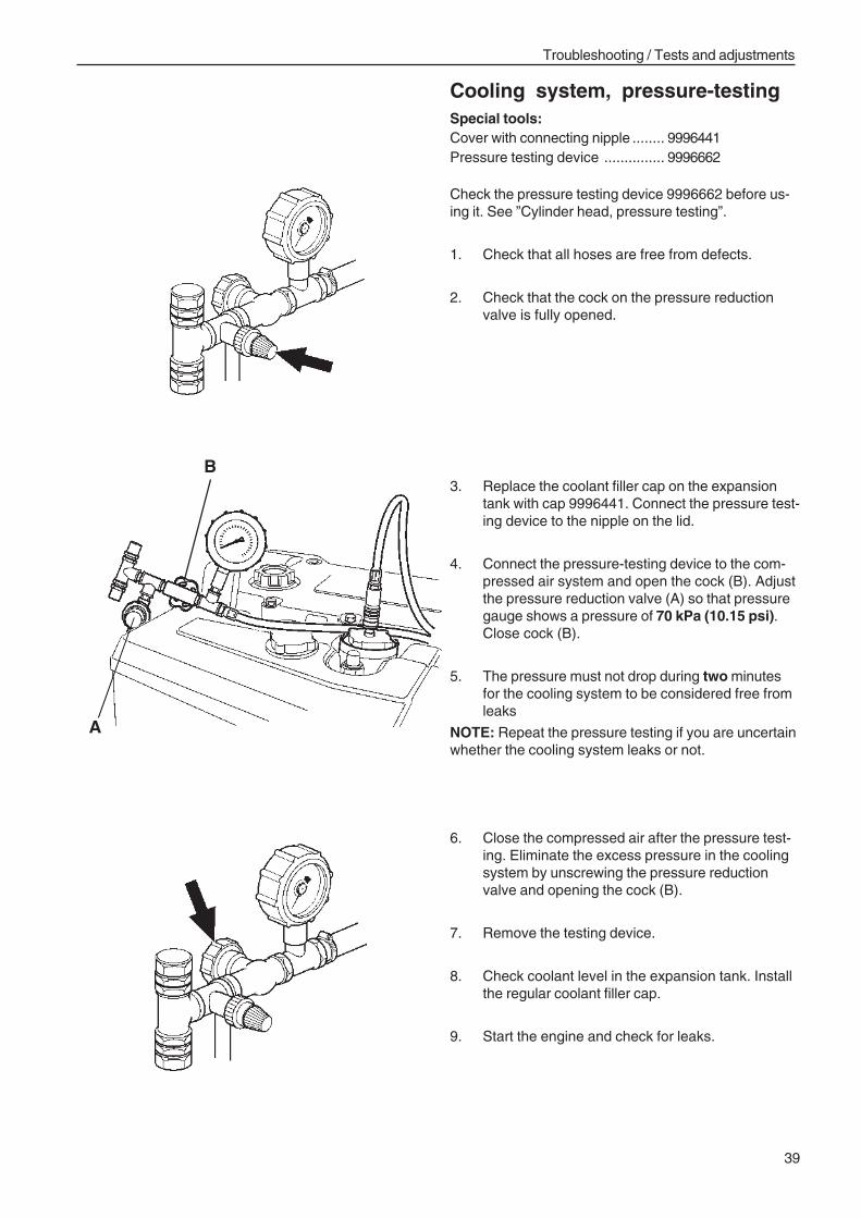
Troubleshooting / Tests and adjustments
39
Cooling system, pressure-testingSpecial tools:Cover with connecting nipple ........ 9996441Pressure testing device ............... 9996662
Check the pressure testing device 9996662 before us-ing it. See ”Cylinder head, pressure testing”.
1. Check that all hoses are free from defects.
2. Check that the cock on the pressure reductionvalve is fully opened.
3. Replace the coolant filler cap on the expansiontank with cap 9996441. Connect the pressure test-ing device to the nipple on the lid.
4. Connect the pressure-testing device to the com-pressed air system and open the cock (B). Adjustthe pressure reduction valve (A) so that pressuregauge shows a pressure of 70 kPa (10.15 psi).Close cock (B).
5. The pressure must not drop during two minutesfor the cooling system to be considered free fromleaks
NOTE: Repeat the pressure testing if you are uncertainwhether the cooling system leaks or not.
6. Close the compressed air after the pressure test-ing. Eliminate the excess pressure in the coolingsystem by unscrewing the pressure reductionvalve and opening the cock (B).
7. Remove the testing device.
8. Check coolant level in the expansion tank. Installthe regular coolant filler cap.
9. Start the engine and check for leaks.
B
A
Troubleshooting / Tests and adjustments
40
Boost pressure, troubleshooting
Boost pressure, checkSpecial tools:Connecting nipple ......................... 9996666Hose ............................................ 9998493Pressure gauge ............................ 9998339
1. Connect the nipple with hose and pressuregauge to the measurement outlet on the inletmanifold , see "Location of measurement outlet".
2. Compare the pressure with the value that can beread off from the VODIA tool, see "Workshopmanual, EMS 2"If the two values differ, the pressure sensor isfaulty and must be replaced.
Pressure drop indicator,checking
25605-31. Check that the air filter is clean and that there
are no obstructions for the intake air.
2. Remove the pressure drop indicator from the airfilter housing
3. Check the pressure drop indicator by sucking airuntil the dial indicator shows red. Reset the fuseby pressing the yellow top.
4. When the air filter is clogged, for example, andvacuum is created, the pressure drop indicatorshows red. Replace dial indicator if it does notwork as in point 3, above.
5. Install the pressure drop indicator on the air filterhousing
Troubleshooting / Tests and adjustments
41
Exhaust system, checking1. Check that the exhaust system is Penta original.
2. Check if exhaust system has been rebuilt, isbent or has damage that prevents the exhaustfrom getting out.If the exhaust system is not a Penta original,has been rebuilt or damaged, the exhaust backpressure may be too high, which leads to lessengine output.
3. If you suspect that the exhaust back pressure istoo high the pressure should be checked, see“Exhaust back pressure, measurement
Charge air cooler, checking
26515-61. Check the charge air cooler for damaged cells or
connections.If it is damaged, replace the charge air cooler.
2. Check the charge air cooler and radiator for ex-ternal clogging.In case of clogging, clean per “Radiator, outsidecleaning”.
Inlet pipe, checking
25614-61. Check that the intake manifolds are clean and
undamaged inside. Squeezed, damaged or dirtyinlet pipes may cause the boost pressure to be-come lower.
Troubleshooting / Tests and adjustments
42
Air intake pipe, checking
26514-61. Check the charge air pipes for visible cracks and
external damage.
2. Check for oil in charge air pipes. If the pipes hasdamage or leakage in sealing rings at connec-tions, the boost pressure will be too low and theengine’s output deteriorates.If the pipes are contaminated by oil inside, thispoints to oil leakage at the turbo’s turbine shaftseal. In that case, replace the turbo complete.
NOTE: If there is oil in charge air pipes and charge airhoses, the charge air cooler and all pipes and hoses inthe charge air system should be very thoroughlycleaned inside, before the engine is started.
Turbocharger, checking
25515-61. Check that the turbo unit item number is
matches the engine version. The wrong turbounit for the engine version may provide chargingpressure that is too low and thus reduce theengine’s output.
2. Check that turbo unit has the correct compressorhousing. If the wrong compressor housing is in-stalled on the turbo, the compressor wheel mayhave been damaged or have too big clearancebetween wheel and housing. In both cases theboost pressure becomes too low.
3. Remove the intake manifold from the turbo-charger.
4. Check the turbo for damage on compressorwheel and for big axial play on the turbine wheelshaft.
5. In case of damage to compressor wheel and ex-cessive axial play, the turbo should be replacedcomplete.
6. Remove exhaust pipe (muffler) from the turboand check the turbine wheel.
7. Check the turbine wheel for damage. If the tur-bine wheel has been damaged, replace the entireturbo.
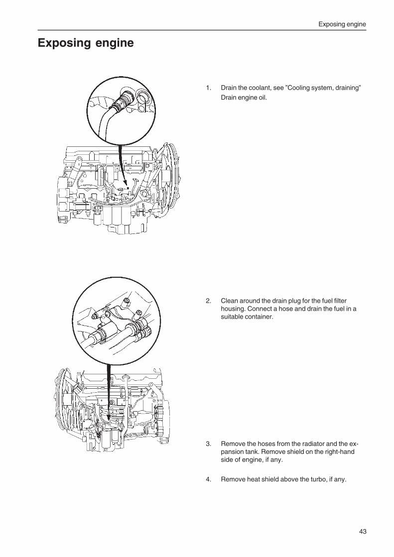
Exposing engine
43
Exposing engine
1. Drain the coolant, see ”Cooling system, draining”
Drain engine oil.
2. Clean around the drain plug for the fuel filterhousing. Connect a hose and drain the fuel in asuitable container.
3. Remove the hoses from the radiator and the ex-pansion tank. Remove shield on the right-handside of engine, if any.
4. Remove heat shield above the turbo, if any.
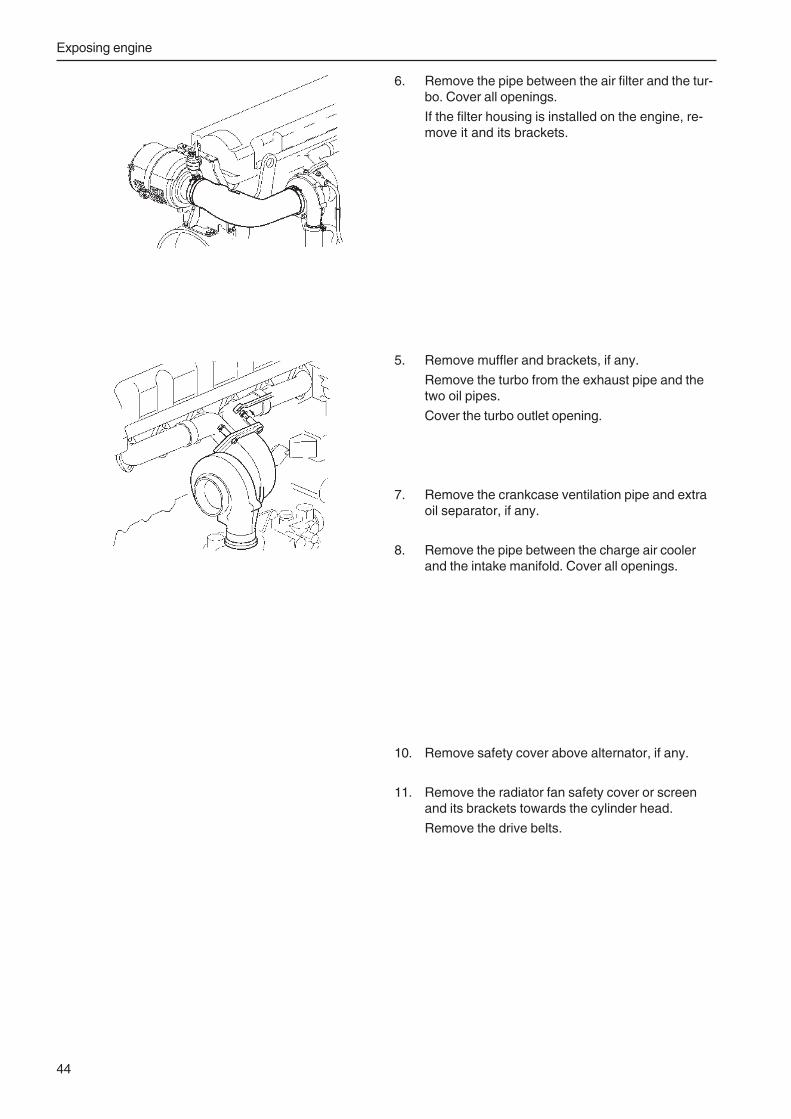
Exposing engine
44
6. Remove the pipe between the air filter and the tur-bo. Cover all openings.
If the filter housing is installed on the engine, re-move it and its brackets.
5. Remove muffler and brackets, if any.
Remove the turbo from the exhaust pipe and thetwo oil pipes.
Cover the turbo outlet opening.
7. Remove the crankcase ventilation pipe and extraoil separator, if any.
8. Remove the pipe between the charge air coolerand the intake manifold. Cover all openings.
10. Remove safety cover above alternator, if any.
11. Remove the radiator fan safety cover or screenand its brackets towards the cylinder head.
Remove the drive belts.

Fixture fitting
45
Fixture fitting
1. Remove cable harness and fuel lines to the con-trol module. Cover all openings.
Remove the control module.
2. Remove fuel and electrical connections. Lift thefuel filter bracket together with the filters.
Cover all fuel connections.
4. Install fixture 9990109 with 6 screws.
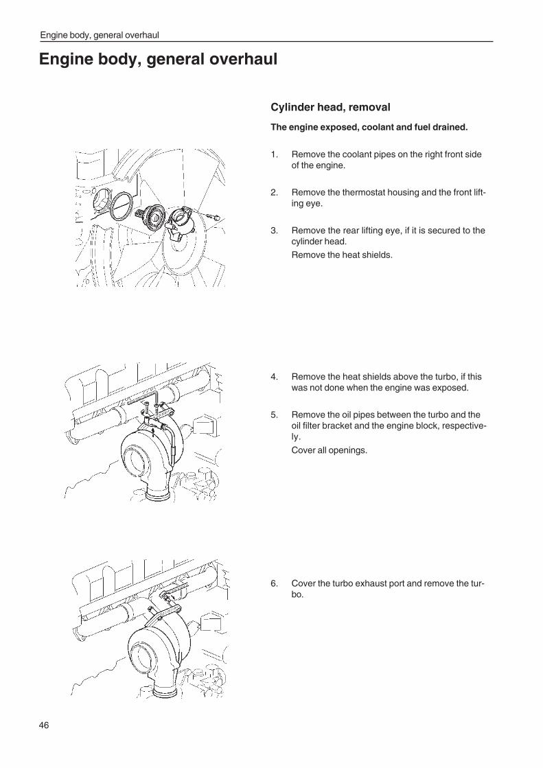
Engine body, general overhaul
46
6. Cover the turbo exhaust port and remove the tur-bo.
Cylinder head, removal
The engine exposed, coolant and fuel drained.
1. Remove the coolant pipes on the right front sideof the engine.
2. Remove the thermostat housing and the front lift-ing eye.
3. Remove the rear lifting eye, if it is secured to thecylinder head.
Remove the heat shields.
4. Remove the heat shields above the turbo, if thiswas not done when the engine was exposed.
5. Remove the oil pipes between the turbo and theoil filter bracket and the engine block, respective-ly.
Cover all openings.
Engine body, general overhaul
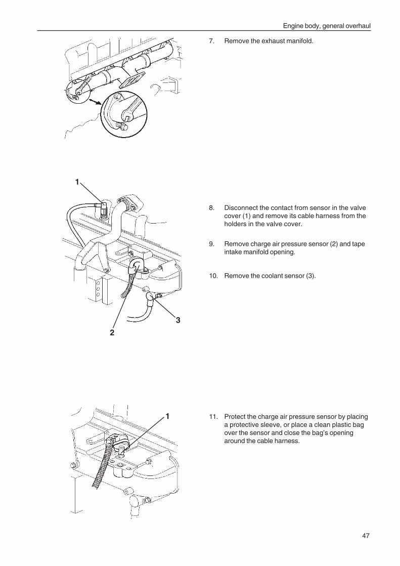
Engine body, general overhaul
47
8. Disconnect the contact from sensor in the valvecover (1) and remove its cable harness from theholders in the valve cover.
9. Remove charge air pressure sensor (2) and tapeintake manifold opening.
10. Remove the coolant sensor (3).
7. Remove the exhaust manifold.
11. Protect the charge air pressure sensor by placinga protective sleeve, or place a clean plastic bagover the sensor and close the bag’s openingaround the cable harness.
1
2
3
1
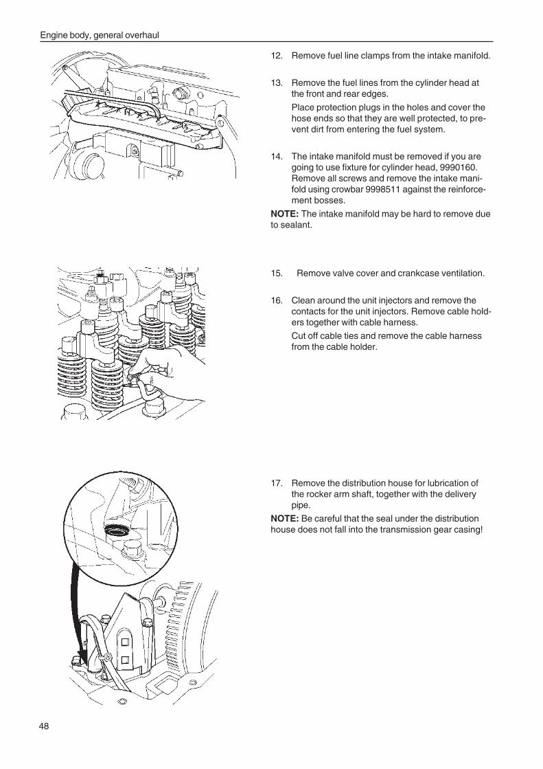
Engine body, general overhaul
48
12. Remove fuel line clamps from the intake manifold.
13. Remove the fuel lines from the cylinder head atthe front and rear edges.
Place protection plugs in the holes and cover thehose ends so that they are well protected, to pre-vent dirt from entering the fuel system.
14. The intake manifold must be removed if you aregoing to use fixture for cylinder head, 9990160.Remove all screws and remove the intake mani-fold using crowbar 9998511 against the reinforce-ment bosses.
NOTE: The intake manifold may be hard to remove dueto sealant.
15. Remove valve cover and crankcase ventilation.
16. Clean around the unit injectors and remove thecontacts for the unit injectors. Remove cable hold-ers together with cable harness.
Cut off cable ties and remove the cable harnessfrom the cable holder.
17. Remove the distribution house for lubrication ofthe rocker arm shaft, together with the deliverypipe.
NOTE: Be careful that the seal under the distributionhouse does not fall into the transmission gear casing!
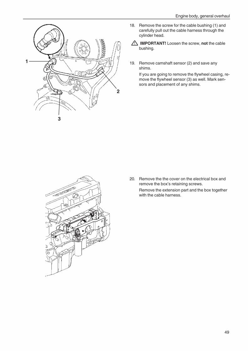
Engine body, general overhaul
49
18. Remove the screw for the cable bushing (1) andcarefully pull out the cable harness through thecylinder head.
IMPORTANT! Loosen the screw, not the cablebushing.
19. Remove camshaft sensor (2) and save anyshims.
If you are going to remove the flywheel casing, re-move the flywheel sensor (3) as well. Mark sen-sors and placement of any shims.
20. Remove the the cover on the electrical box andremove the box’s retaining screws.
Remove the extension part and the box togetherwith the cable harness.
1
2
3
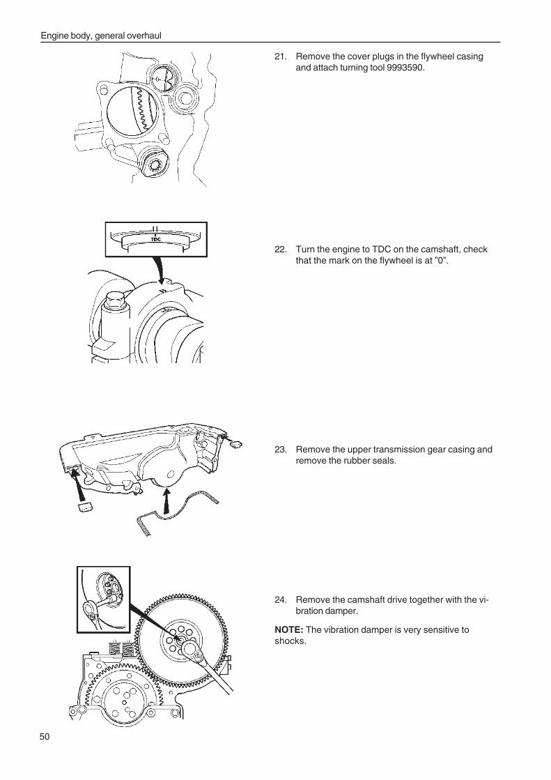
Engine body, general overhaul
50
24. Remove the camshaft drive together with the vi-bration damper.
NOTE: The vibration damper is very sensitive toshocks.
21. Remove the cover plugs in the flywheel casingand attach turning tool 9993590.
22. Turn the engine to TDC on the camshaft, checkthat the mark on the flywheel is at ”0”.
23. Remove the upper transmission gear casing andremove the rubber seals.
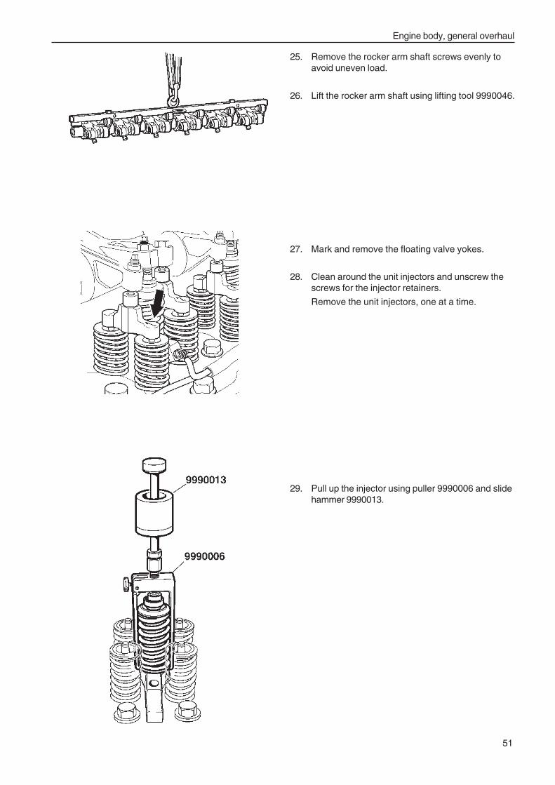
Engine body, general overhaul
51
25. Remove the rocker arm shaft screws evenly toavoid uneven load.
26. Lift the rocker arm shaft using lifting tool 9990046.
27. Mark and remove the floating valve yokes.
28. Clean around the unit injectors and unscrew thescrews for the injector retainers.
Remove the unit injectors, one at a time.
29. Pull up the injector using puller 9990006 and slidehammer 9990013.
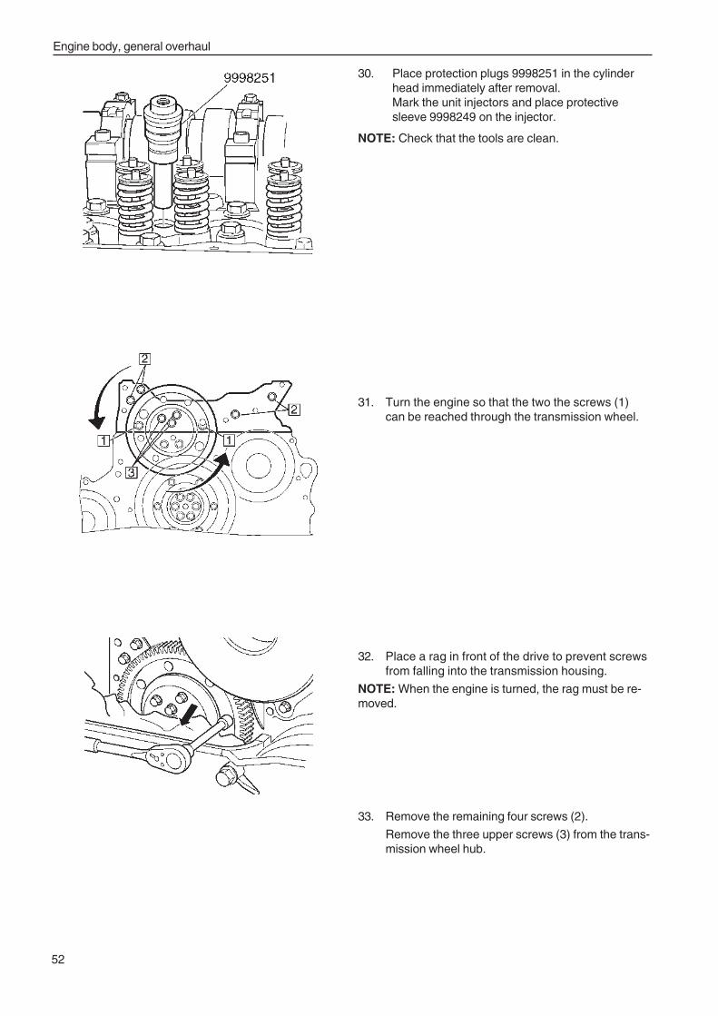
Engine body, general overhaul
52
30. Place protection plugs 9998251 in the cylinderhead immediately after removal.Mark the unit injectors and place protectivesleeve 9998249 on the injector.
NOTE: Check that the tools are clean.
31. Turn the engine so that the two the screws (1)can be reached through the transmission wheel.
32. Place a rag in front of the drive to prevent screwsfrom falling into the transmission housing.
NOTE: When the engine is turned, the rag must be re-moved.
33. Remove the remaining four screws (2).
Remove the three upper screws (3) from the trans-mission wheel hub.
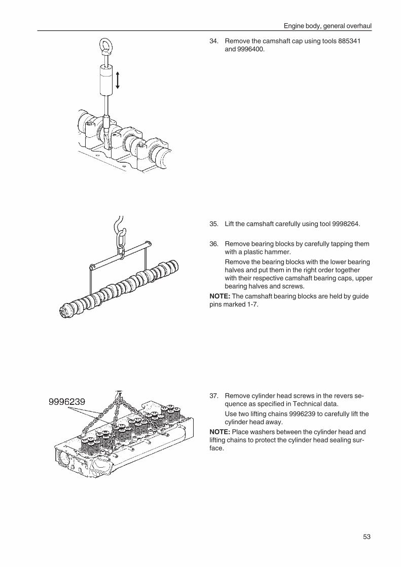
Engine body, general overhaul
53
37. Remove cylinder head screws in the revers se-quence as specified in Technical data.
Use two lifting chains 9996239 to carefully lift thecylinder head away.
NOTE: Place washers between the cylinder head andlifting chains to protect the cylinder head sealing sur-face.
34. Remove the camshaft cap using tools 885341and 9996400.
35. Lift the camshaft carefully using tool 9998264.
36. Remove bearing blocks by carefully tapping themwith a plastic hammer.
Remove the bearing blocks with the lower bearinghalves and put them in the right order togetherwith their respective camshaft bearing caps, upperbearing halves and screws.
NOTE: The camshaft bearing blocks are held by guidepins marked 1-7.
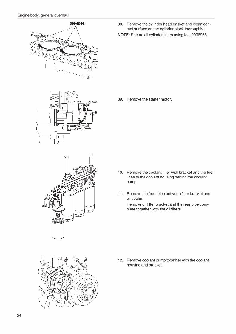
Engine body, general overhaul
54
38. Remove the cylinder head gasket and clean con-tact surface on the cylinder block thoroughly.
NOTE: Secure all cylinder liners using tool 9996966.
39. Remove the starter motor.
40. Remove the coolant filter with bracket and the fuellines to the coolant housing behind the coolantpump.
41. Remove the front pipe between filter bracket andoil cooler.
Remove oil filter bracket and the rear pipe com-plete together with the oil filters.
42. Remove coolant pump together with the coolanthousing and bracket.
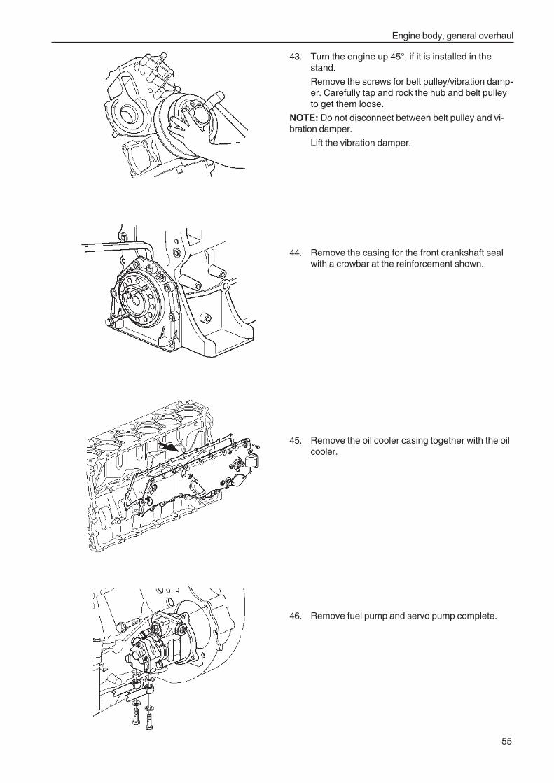
Engine body, general overhaul
55
43. Turn the engine up 45°, if it is installed in thestand.
Remove the screws for belt pulley/vibration damp-er. Carefully tap and rock the hub and belt pulleyto get them loose.
NOTE: Do not disconnect between belt pulley and vi-bration damper.
Lift the vibration damper.
44. Remove the casing for the front crankshaft sealwith a crowbar at the reinforcement shown.
45. Remove the oil cooler casing together with the oilcooler.
46. Remove fuel pump and servo pump complete.
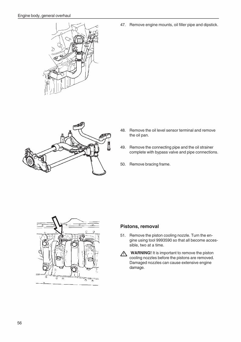
Engine body, general overhaul
56
47. Remove engine mounts, oil filler pipe and dipstick.
48. Remove the oil level sensor terminal and removethe oil pan.
49. Remove the connecting pipe and the oil strainercomplete with bypass valve and pipe connections.
50. Remove bracing frame.
Pistons, removal
51. Remove the piston cooling nozzle. Turn the en-gine using tool 9993590 so that all become acces-sible, two at a time.
WARNING! It is important to remove the pistoncooling nozzles before the pistons are removed.Damaged nozzles can cause extensive enginedamage.
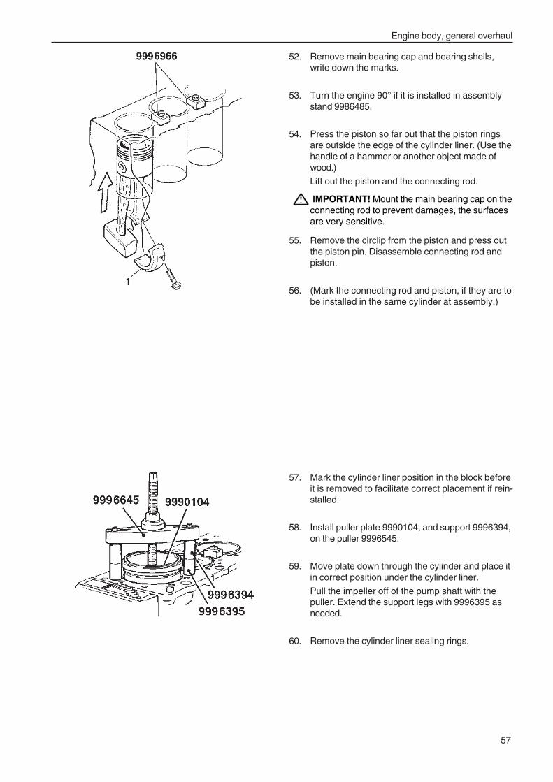
Engine body, general overhaul
57
52. Remove main bearing cap and bearing shells,write down the marks.
53. Turn the engine 90° if it is installed in assemblystand 9986485.
54. Press the piston so far out that the piston ringsare outside the edge of the cylinder liner. (Use thehandle of a hammer or another object made ofwood.)
Lift out the piston and the connecting rod.
IMPORTANT! Mount the main bearing cap on theconnecting rod to prevent damages, the surfacesare very sensitive.
55. Remove the circlip from the piston and press outthe piston pin. Disassemble connecting rod andpiston.
56. (Mark the connecting rod and piston, if they are tobe installed in the same cylinder at assembly.)
57. Mark the cylinder liner position in the block beforeit is removed to facilitate correct placement if rein-stalled.
58. Install puller plate 9990104, and support 9996394,on the puller 9996545.
59. Move plate down through the cylinder and place itin correct position under the cylinder liner.
Pull the impeller off of the pump shaft with thepuller. Extend the support legs with 9996395 asneeded.
60. Remove the cylinder liner sealing rings.
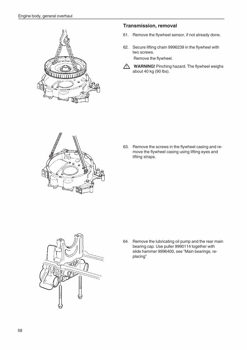
Engine body, general overhaul
58
Transmission, removal
61. Remove the flywheel sensor, if not already done.
62. Secure lifting chain 9996239 in the flywheel withtwo screws.
Remove the flywheel.
WARNING! Pinching hazard. The flywheel weighsabout 40 kg (90 lbs).
63. Remove the screws in the flywheel casing and re-move the flywheel casing using lifting eyes andlifting straps.
64. Remove the lubricating oil pump and the rear mainbearing cap. Use puller 9990114 together withslide hammer 9996400, see ”Main bearings, re-placing”
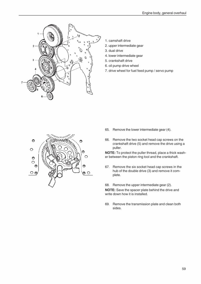
Engine body, general overhaul
59
1. camshaft drive
2. upper intermediate gear
3. dual drive
4. lower intermediate gear
5. crankshaft drive
6. oil pump drive wheel
7. drive wheel for fuel feed pump / servo pump
65. Remove the lower intermediate gear (4).
66. Remove the two socket head cap screws on thecrankshaft drive (5) and remove the drive using apuller.
NOTE: To protect the puller thread, place a thick wash-er between the piston ring tool and the crankshaft.
67. Remove the six socket head cap screws in thehub of the double drive (3) and remove it com-plete.
68. Remove the upper intermediate gear (2).
NOTE: Save the spacer plate behind the drive andwrite down how it is installed.
69. Remove the transmission plate and clean bothsides.
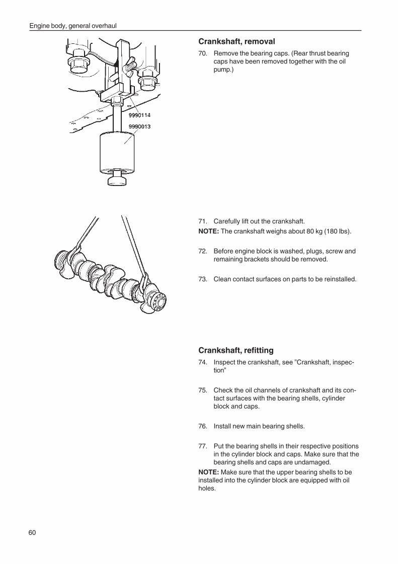
Engine body, general overhaul
60
Crankshaft, removal70. Remove the bearing caps. (Rear thrust bearing
caps have been removed together with the oilpump.)
71. Carefully lift out the crankshaft.
NOTE: The crankshaft weighs about 80 kg (180 lbs).
72. Before engine block is washed, plugs, screw andremaining brackets should be removed.
73. Clean contact surfaces on parts to be reinstalled.
Crankshaft, refitting74. Inspect the crankshaft, see ”Crankshaft, inspec-
tion”
75. Check the oil channels of crankshaft and its con-tact surfaces with the bearing shells, cylinderblock and caps.
76. Install new main bearing shells.
77. Put the bearing shells in their respective positionsin the cylinder block and caps. Make sure that thebearing shells and caps are undamaged.
NOTE: Make sure that the upper bearing shells to beinstalled into the cylinder block are equipped with oilholes.
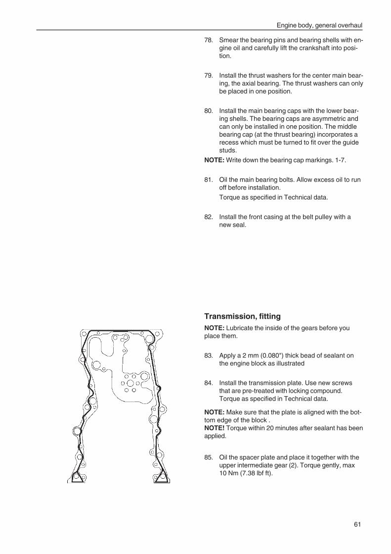
Engine body, general overhaul
61
Transmission, fittingNOTE: Lubricate the inside of the gears before youplace them.
83. Apply a 2 mm (0.080") thick bead of sealant onthe engine block as illustrated
84. Install the transmission plate. Use new screwsthat are pre-treated with locking compound.Torque as specified in Technical data.
NOTE: Make sure that the plate is aligned with the bot-tom edge of the block .NOTE! Torque within 20 minutes after sealant has beenapplied.
85. Oil the spacer plate and place it together with theupper intermediate gear (2). Torque gently, max10 Nm (7.38 lbf ft).
78. Smear the bearing pins and bearing shells with en-gine oil and carefully lift the crankshaft into posi-tion.
79. Install the thrust washers for the center main bear-ing, the axial bearing. The thrust washers can onlybe placed in one position.
80. Install the main bearing caps with the lower bear-ing shells. The bearing caps are asymmetric andcan only be installed in one position. The middlebearing cap (at the thrust bearing) incorporates arecess which must be turned to fit over the guidestuds.
NOTE: Write down the bearing cap markings. 1-7.
81. Oil the main bearing bolts. Allow excess oil to runoff before installation.
Torque as specified in Technical data.
82. Install the front casing at the belt pulley with anew seal.
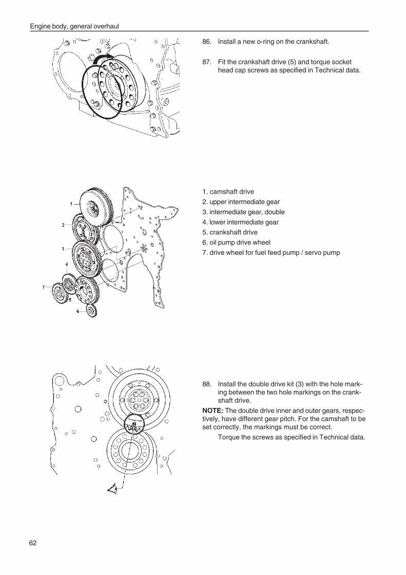
Engine body, general overhaul
62
86. Install a new o-ring on the crankshaft.
87. Fit the crankshaft drive (5) and torque sockethead cap screws as specified in Technical data.
1. camshaft drive
2. upper intermediate gear
3. intermediate gear, double
4. lower intermediate gear
5. crankshaft drive
6. oil pump drive wheel
7. drive wheel for fuel feed pump / servo pump
88. Install the double drive kit (3) with the hole mark-ing between the two hole markings on the crank-shaft drive.
NOTE: The double drive inner and outer gears, respec-tively, have different gear pitch. For the camshaft to beset correctly, the markings must be correct.
Torque the screws as specified in Technical data.
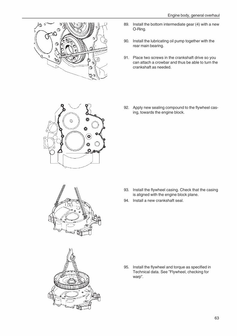
Engine body, general overhaul
63
89. Install the bottom intermediate gear (4) with a newO-Ring.
90. Install the lubricating oil pump together with therear main bearing.
91. Place two screws in the crankshaft drive so youcan attach a crowbar and thus be able to turn thecrankshaft as needed.
92. Apply new sealing compound to the flywheel cas-ing, towards the engine block.
93. Install the flywheel casing. Check that the casingis aligned with the engine block plane.
94. Install a new crankshaft seal.
95. Install the flywheel and torque as specified inTechnical data. See ”Flywheel, checking forwarp”.
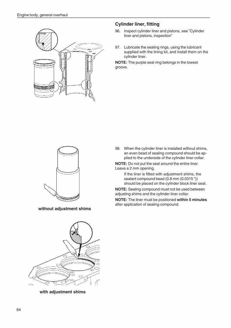
Engine body, general overhaul
64
Cylinder liner, fitting96. Inspect cylinder liner and pistons, see ”Cylinder
liner and pistons, inspection”
97. Lubricate the sealing rings, using the lubricantsupplied with the lining kit, and install them on thecylinder liner.
NOTE: The purple seal ring belongs in the lowestgroove.
98. When the cylinder liner is installed without shims,an even bead of sealing compound should be ap-plied to the underside of the cylinder liner collar.
NOTE: Do not put the seal around the entire liner.Leave a 2 mm opening.
If the liner is fitted with adjustment shims, thesealant compound bead (0.8 mm (0.0315 “))should be placed on the cylinder block liner seat.
NOTE: Sealing compound must not be used betweenadjusting shims and the cylinder liner collar.
NOTE: The liner must be positioned within 5 minutesafter application of sealing compound.
without adjustment shims
with adjustment shims
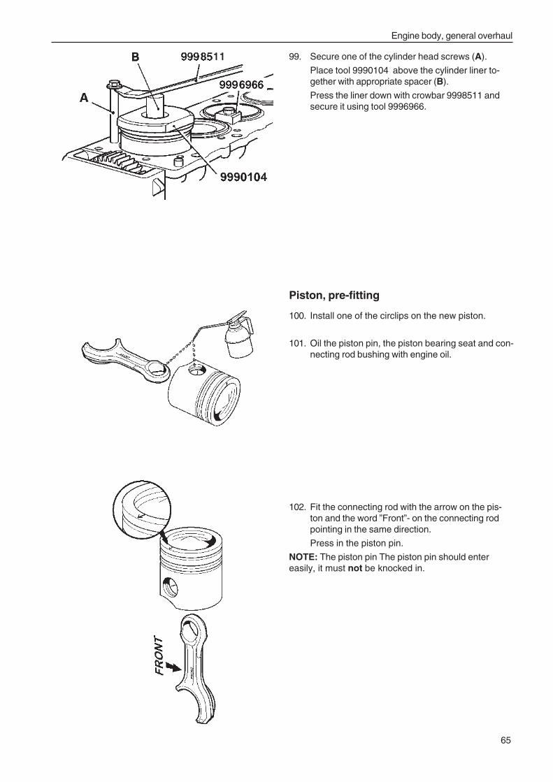
Engine body, general overhaul
65
Piston, pre-fitting
100. Install one of the circlips on the new piston.
101. Oil the piston pin, the piston bearing seat and con-necting rod bushing with engine oil.
102. Fit the connecting rod with the arrow on the pis-ton and the word ”Front”- on the connecting rodpointing in the same direction.
Press in the piston pin.
NOTE: The piston pin The piston pin should entereasily, it must not be knocked in.
99. Secure one of the cylinder head screws (A).
Place tool 9990104 above the cylinder liner to-gether with appropriate spacer (B).
Press the liner down with crowbar 9998511 andsecure it using tool 9996966.
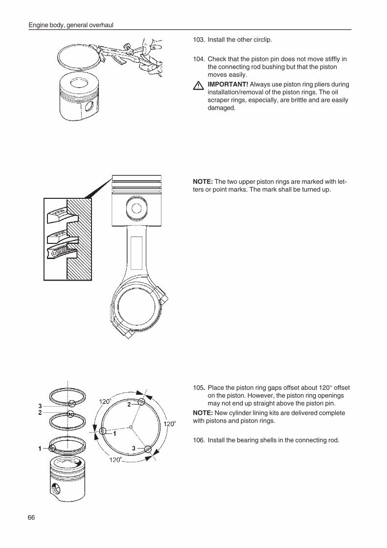
Engine body, general overhaul
66
NOTE: The two upper piston rings are marked with let-ters or point marks. The mark shall be turned up.
105. Place the piston ring gaps offset about 120° offseton the piston. However, the piston ring openingsmay not end up straight above the piston pin.
NOTE: New cylinder lining kits are delivered completewith pistons and piston rings.
106. Install the bearing shells in the connecting rod.
103. Install the other circlip.
104. Check that the piston pin does not move stiffly inthe connecting rod bushing but that the pistonmoves easily.
IMPORTANT! Always use piston ring pliers duringinstallation/removal of the piston rings. The oilscraper rings, especially, are brittle and are easilydamaged.
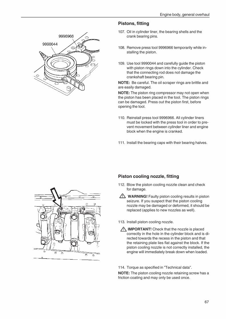
Engine body, general overhaul
67
Pistons, fitting
107. Oil in cylinder liner, the bearing shells and thecrank bearing pins.
108. Remove press tool 9996966 temporarily while in-stalling the piston.
109. Use tool 9990044 and carefully guide the pistonwith piston rings down into the cylinder. Checkthat the connecting rod does not damage thecrankshaft bearing pin.
NOTE: Be careful. The oil scraper rings are brittle andare easily damaged.
NOTE: The piston ring compressor may not open whenthe piston has been placed in the tool. The piston ringscan be damaged. Press out the piston first, beforeopening the tool.
110. Reinstall press tool 9996966. All cylinder linersmust be locked with the press tool in order to pre-vent movement between cylinder liner and engineblock when the engine is cranked.
111. Install the bearing caps with their bearing halves.
Piston cooling nozzle, fitting
112. Blow the piston cooling nozzle clean and checkfor damage.
WARNING! Faulty piston cooling results in pistonseizure. If you suspect that the piston coolingnozzle may be damaged or deformed, it should bereplaced (applies to new nozzles as well).
113. Install piston cooling nozzle.
IMPORTANT! Check that the nozzle is placedcorrectly in the hole in the cylinder block and is di-rected towards the recess in the piston and thatthe retaining plate lies flat against the block. If thepiston cooling nozzle is not correctly installed, theengine will immediately break down when loaded.
114. Torque as specified in ”Technical data”.
NOTE: The piston cooling nozzle retaining screw has afriction coating and may only be used once.
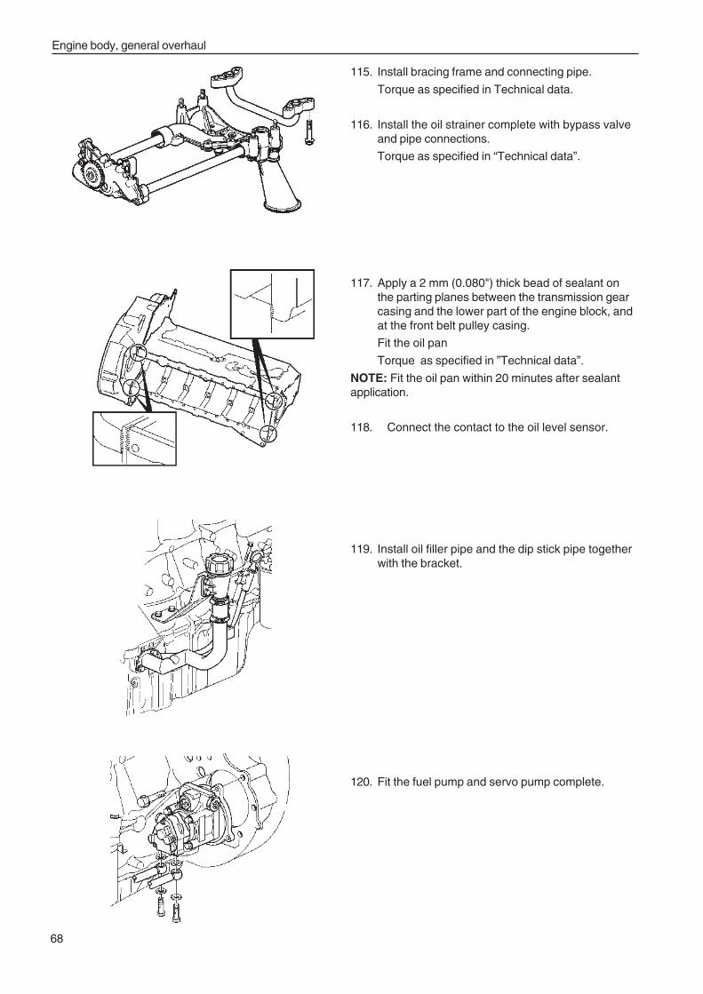
Engine body, general overhaul
68
115. Install bracing frame and connecting pipe.
Torque as specified in Technical data.
116. Install the oil strainer complete with bypass valveand pipe connections.
Torque as specified in “Technical data”.
117. Apply a 2 mm (0.080") thick bead of sealant onthe parting planes between the transmission gearcasing and the lower part of the engine block, andat the front belt pulley casing.
Fit the oil pan
Torque as specified in ”Technical data”.
NOTE: Fit the oil pan within 20 minutes after sealantapplication.
118. Connect the contact to the oil level sensor.
119. Install oil filler pipe and the dip stick pipe togetherwith the bracket.
120. Fit the fuel pump and servo pump complete.
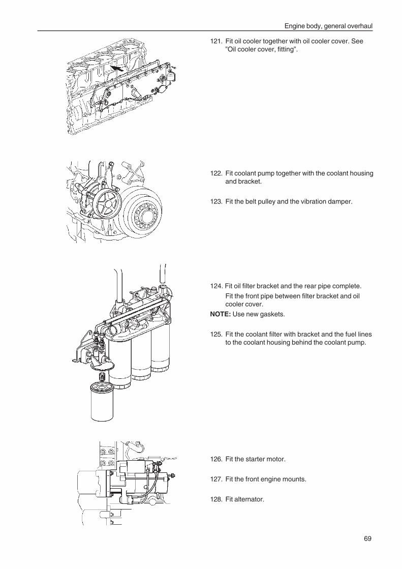
Engine body, general overhaul
69
121. Fit oil cooler together with oil cooler cover. See”Oil cooler cover, fitting”.
122. Fit coolant pump together with the coolant housingand bracket.
123. Fit the belt pulley and the vibration damper.
124. Fit oil filter bracket and the rear pipe complete.
Fit the front pipe between filter bracket and oilcooler cover.
NOTE: Use new gaskets.
125. Fit the coolant filter with bracket and the fuel linesto the coolant housing behind the coolant pump.
126. Fit the starter motor.
127. Fit the front engine mounts.
128. Fit alternator.
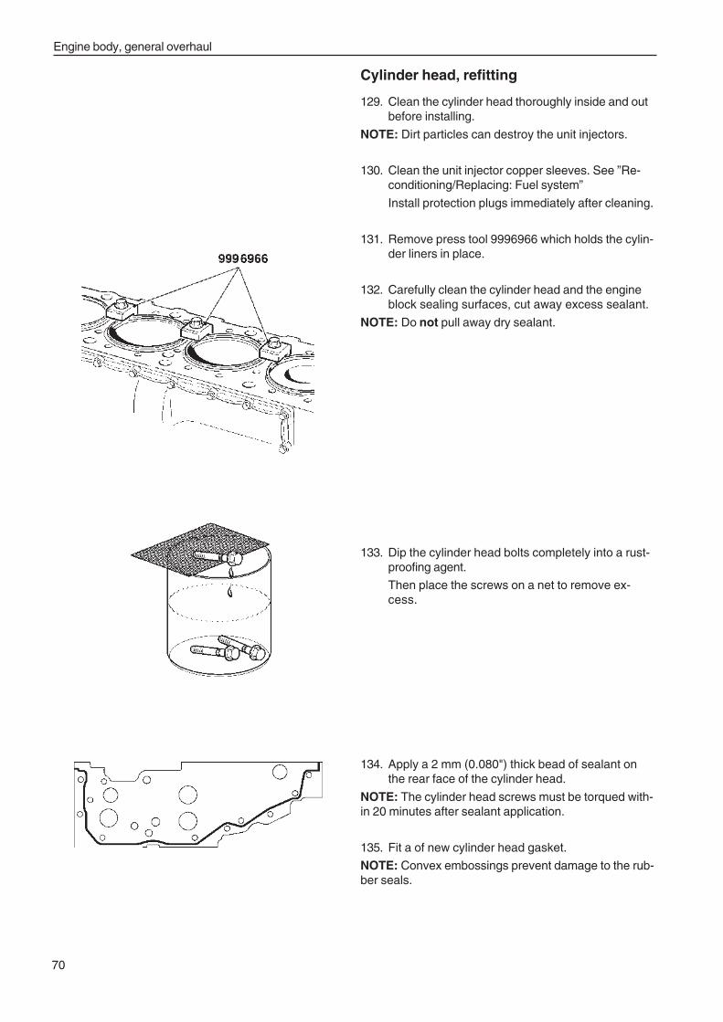
Engine body, general overhaul
70
Cylinder head, refitting
129. Clean the cylinder head thoroughly inside and outbefore installing.
NOTE: Dirt particles can destroy the unit injectors.
130. Clean the unit injector copper sleeves. See ”Re-conditioning/Replacing: Fuel system”
Install protection plugs immediately after cleaning.
131. Remove press tool 9996966 which holds the cylin-der liners in place.
132. Carefully clean the cylinder head and the engineblock sealing surfaces, cut away excess sealant.
NOTE: Do not pull away dry sealant.
133. Dip the cylinder head bolts completely into a rust-proofing agent.
Then place the screws on a net to remove ex-cess.
134. Apply a 2 mm (0.080") thick bead of sealant onthe rear face of the cylinder head.
NOTE: The cylinder head screws must be torqued with-in 20 minutes after sealant application.
135. Fit a of new cylinder head gasket.
NOTE: Convex embossings prevent damage to the rub-ber seals.
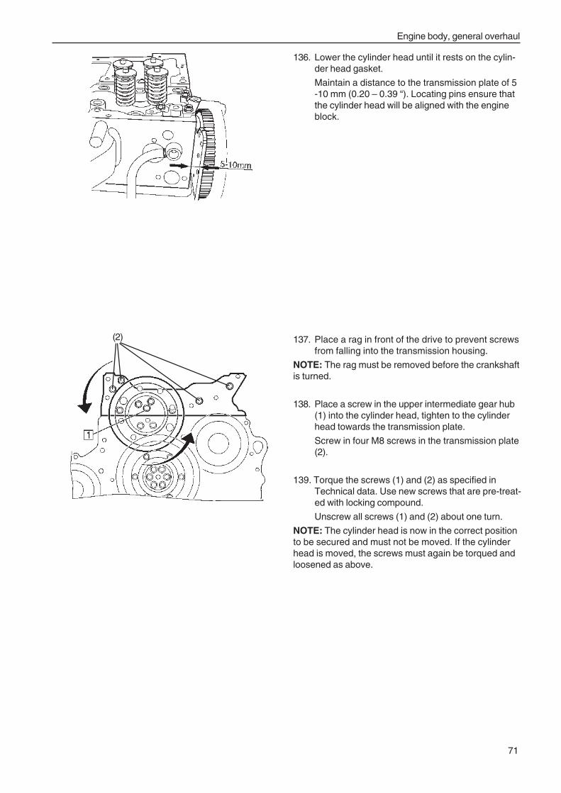
Engine body, general overhaul
71
136. Lower the cylinder head until it rests on the cylin-der head gasket.
Maintain a distance to the transmission plate of 5-10 mm (0.20 – 0.39 “). Locating pins ensure thatthe cylinder head will be aligned with the engineblock.
137. Place a rag in front of the drive to prevent screwsfrom falling into the transmission housing.
NOTE: The rag must be removed before the crankshaftis turned.
138. Place a screw in the upper intermediate gear hub(1) into the cylinder head, tighten to the cylinderhead towards the transmission plate.
Screw in four M8 screws in the transmission plate(2).
139. Torque the screws (1) and (2) as specified inTechnical data. Use new screws that are pre-treat-ed with locking compound.
Unscrew all screws (1) and (2) about one turn.
NOTE: The cylinder head is now in the correct positionto be secured and must not be moved. If the cylinderhead is moved, the screws must again be torqued andloosened as above.
(2)
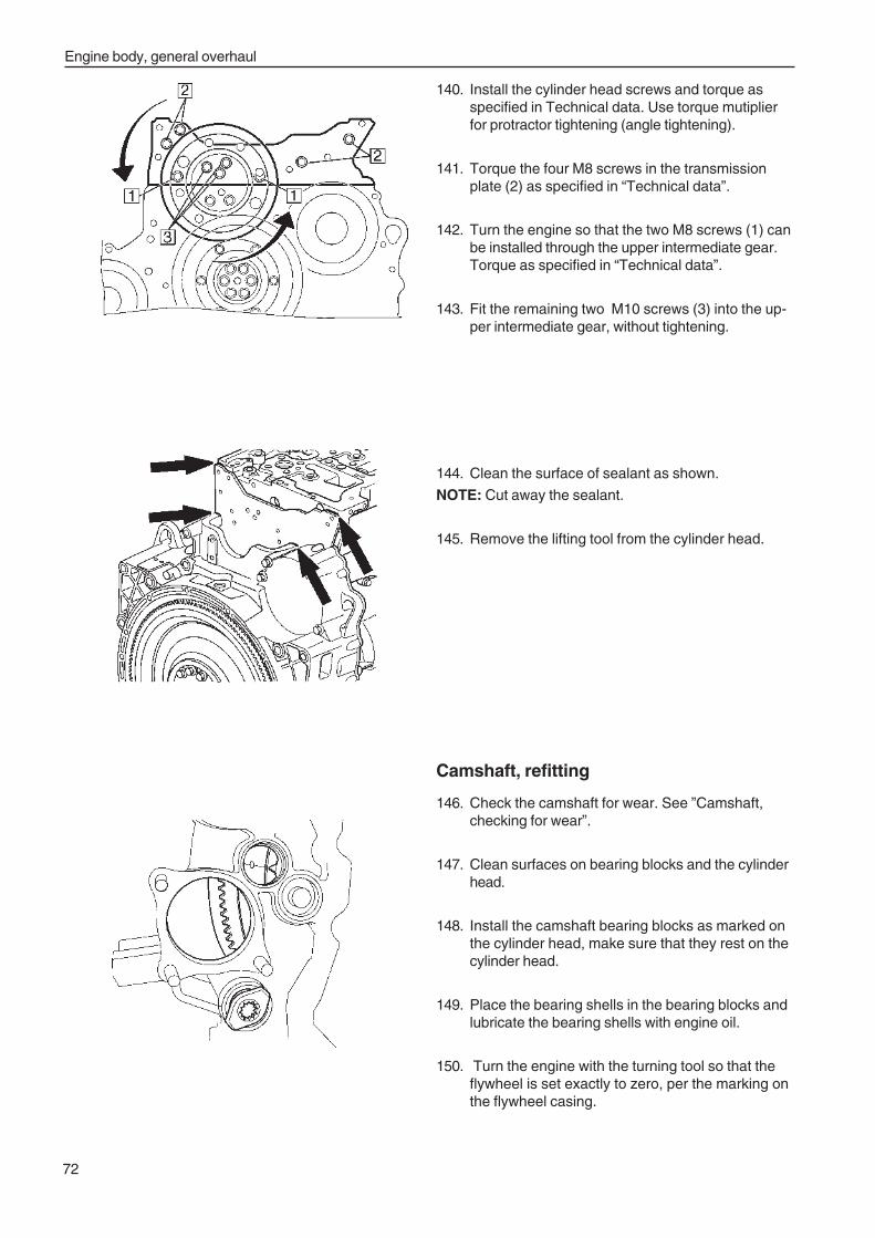
Engine body, general overhaul
72
140. Install the cylinder head screws and torque asspecified in Technical data. Use torque mutiplierfor protractor tightening (angle tightening).
141. Torque the four M8 screws in the transmissionplate (2) as specified in “Technical data”.
142. Turn the engine so that the two M8 screws (1) canbe installed through the upper intermediate gear.Torque as specified in “Technical data”.
143. Fit the remaining two M10 screws (3) into the up-per intermediate gear, without tightening.
144. Clean the surface of sealant as shown.
NOTE: Cut away the sealant.
145. Remove the lifting tool from the cylinder head.
Camshaft, refitting
146. Check the camshaft for wear. See ”Camshaft,checking for wear”.
147. Clean surfaces on bearing blocks and the cylinderhead.
148. Install the camshaft bearing blocks as marked onthe cylinder head, make sure that they rest on thecylinder head.
149. Place the bearing shells in the bearing blocks andlubricate the bearing shells with engine oil.
150. Turn the engine with the turning tool so that theflywheel is set exactly to zero, per the marking onthe flywheel casing.
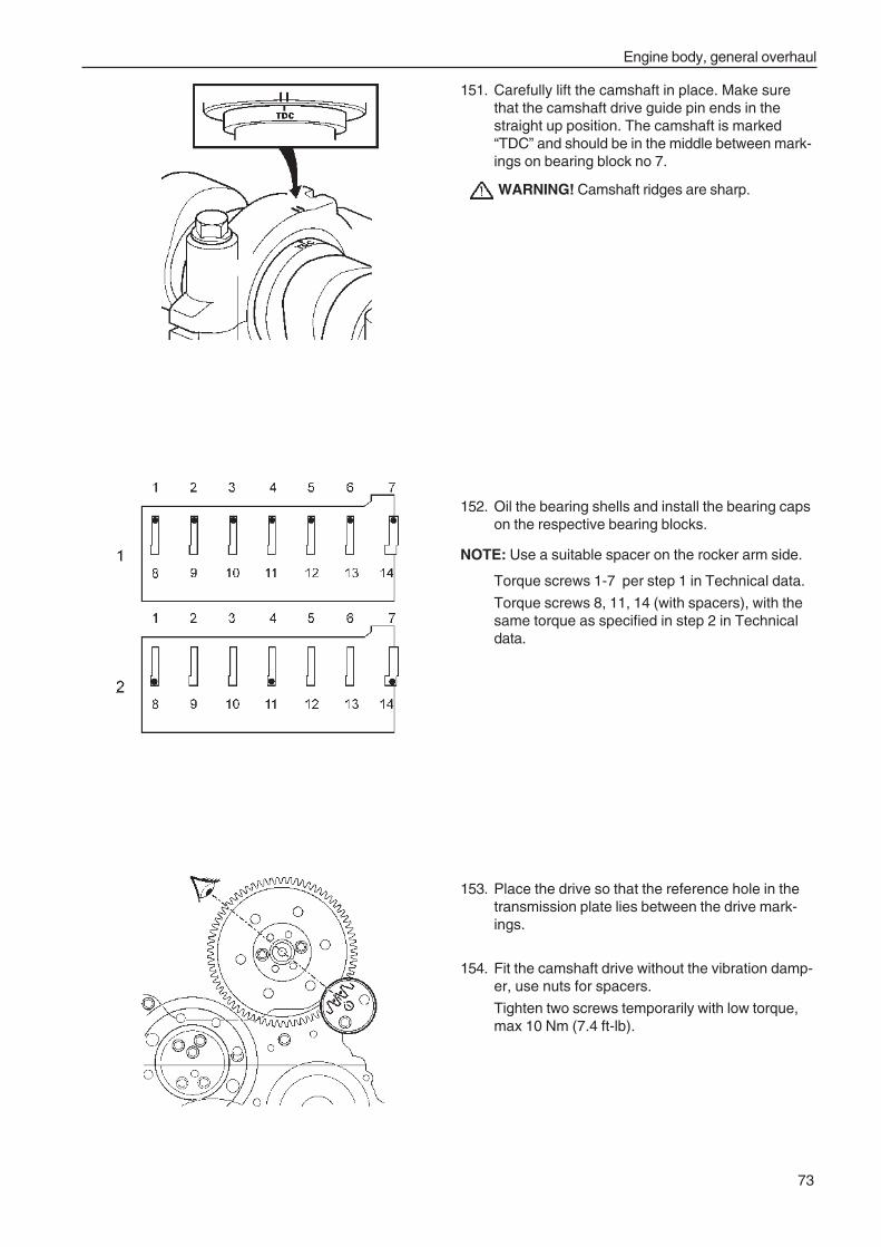
Engine body, general overhaul
73
153. Place the drive so that the reference hole in thetransmission plate lies between the drive mark-ings.
154. Fit the camshaft drive without the vibration damp-er, use nuts for spacers.
Tighten two screws temporarily with low torque,max 10 Nm (7.4 ft-lb).
151. Carefully lift the camshaft in place. Make surethat the camshaft drive guide pin ends in thestraight up position. The camshaft is marked“TDC” and should be in the middle between mark-ings on bearing block no 7.
WARNING! Camshaft ridges are sharp.
152. Oil the bearing shells and install the bearing capson the respective bearing blocks.
NOTE: Use a suitable spacer on the rocker arm side.
Torque screws 1-7 per step 1 in Technical data.
Torque screws 8, 11, 14 (with spacers), with thesame torque as specified in step 2 in Technicaldata.
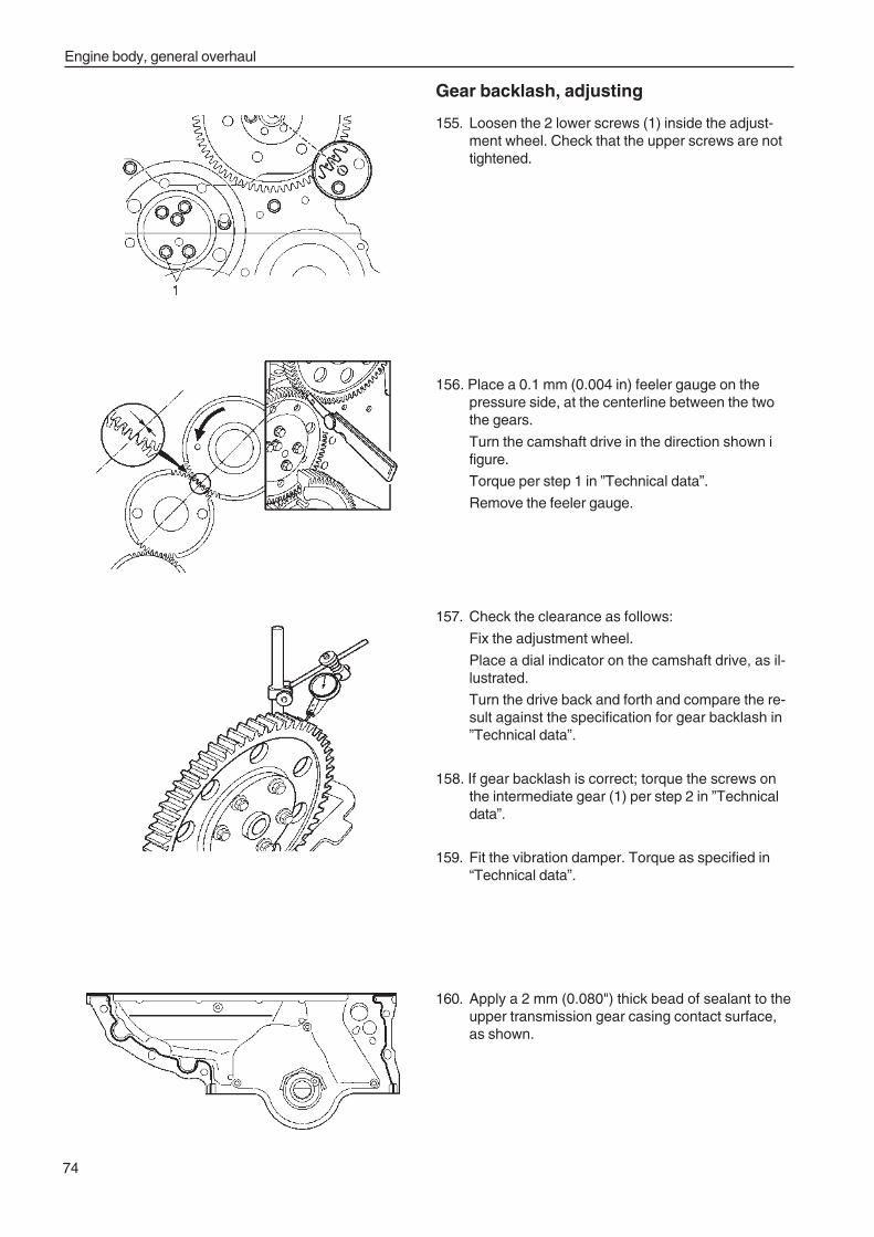
Engine body, general overhaul
74
Gear backlash, adjusting
155. Loosen the 2 lower screws (1) inside the adjust-ment wheel. Check that the upper screws are nottightened.
156. Place a 0.1 mm (0.004 in) feeler gauge on thepressure side, at the centerline between the twothe gears.
Turn the camshaft drive in the direction shown ifigure.
Torque per step 1 in ”Technical data”.
Remove the feeler gauge.
157. Check the clearance as follows:
Fix the adjustment wheel.
Place a dial indicator on the camshaft drive, as il-lustrated.
Turn the drive back and forth and compare the re-sult against the specification for gear backlash in”Technical data”.
158. If gear backlash is correct; torque the screws onthe intermediate gear (1) per step 2 in ”Technicaldata”.
159. Fit the vibration damper. Torque as specified in“Technical data”.
160. Apply a 2 mm (0.080") thick bead of sealant to theupper transmission gear casing contact surface,as shown.
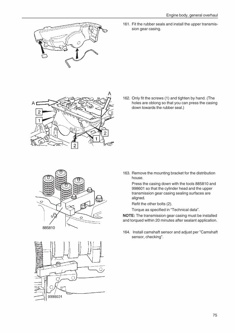
Engine body, general overhaul
75
161. Fit the rubber seals and install the upper transmis-sion gear casing.
162. Only fit the screws (1) and tighten by hand. (Theholes are oblong so that you can press the casingdown towards the rubber seal.)
163. Remove the mounting bracket for the distributionhouse.
Press the casing down with the tools 885810 and998601 so that the cylinder head and the uppertransmission gear casing sealing surfaces arealigned.
Refit the other bolts (2).
Torque as specified in “Technical data”.
NOTE: The transmission gear casing must be installedand torqued within 20 minutes after sealant application.
164. Install camshaft sensor and adjust per ”Camshaftsensor, checking”.
885810
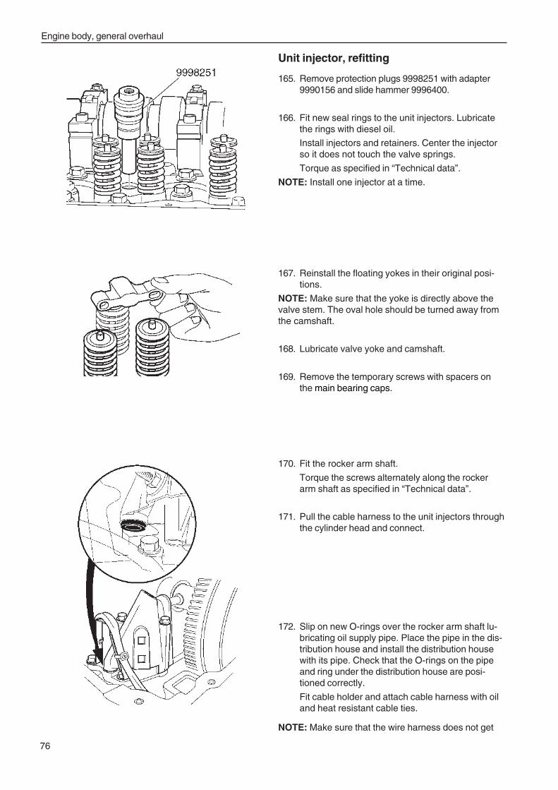
Engine body, general overhaul
76
Unit injector, refitting
165. Remove protection plugs 9998251 with adapter9990156 and slide hammer 9996400.
166. Fit new seal rings to the unit injectors. Lubricatethe rings with diesel oil.
Install injectors and retainers. Center the injectorso it does not touch the valve springs.
Torque as specified in “Technical data”.
NOTE: Install one injector at a time.
167. Reinstall the floating yokes in their original posi-tions.
NOTE: Make sure that the yoke is directly above thevalve stem. The oval hole should be turned away fromthe camshaft.
168. Lubricate valve yoke and camshaft.
169. Remove the temporary screws with spacers onthe main bearing caps.
170. Fit the rocker arm shaft.
Torque the screws alternately along the rockerarm shaft as specified in “Technical data”.
171. Pull the cable harness to the unit injectors throughthe cylinder head and connect.
172. Slip on new O-rings over the rocker arm shaft lu-bricating oil supply pipe. Place the pipe in the dis-tribution house and install the distribution housewith its pipe. Check that the O-rings on the pipeand ring under the distribution house are posi-tioned correctly.
Fit cable holder and attach cable harness with oiland heat resistant cable ties.
NOTE: Make sure that the wire harness does not get
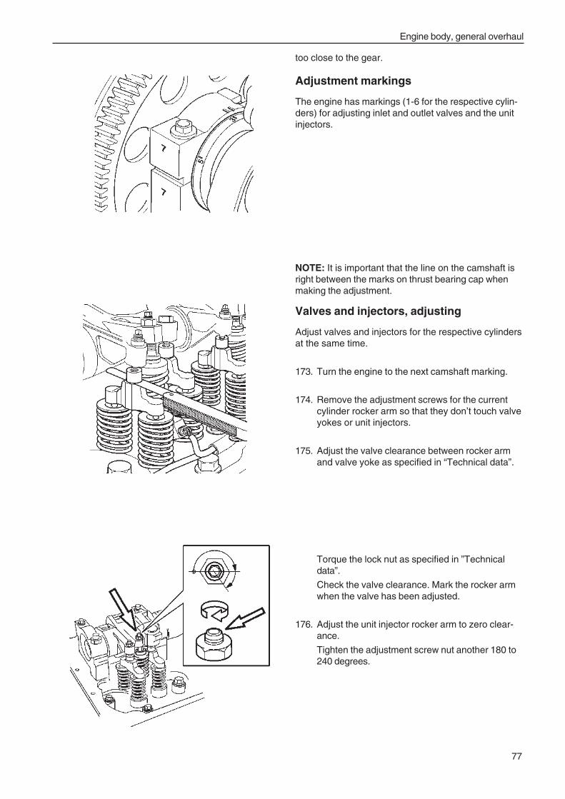
Engine body, general overhaul
77
Torque the lock nut as specified in ”Technicaldata”.
Check the valve clearance. Mark the rocker armwhen the valve has been adjusted.
176. Adjust the unit injector rocker arm to zero clear-ance.
Tighten the adjustment screw nut another 180 to240 degrees.
too close to the gear.
Adjustment markings
The engine has markings (1-6 for the respective cylin-ders) for adjusting inlet and outlet valves and the unitinjectors.
NOTE: It is important that the line on the camshaft isright between the marks on thrust bearing cap whenmaking the adjustment.
Valves and injectors, adjusting
Adjust valves and injectors for the respective cylindersat the same time.
173. Turn the engine to the next camshaft marking.
174. Remove the adjustment screws for the currentcylinder rocker arm so that they don’t touch valveyokes or unit injectors.
175. Adjust the valve clearance between rocker armand valve yoke as specified in “Technical data”.
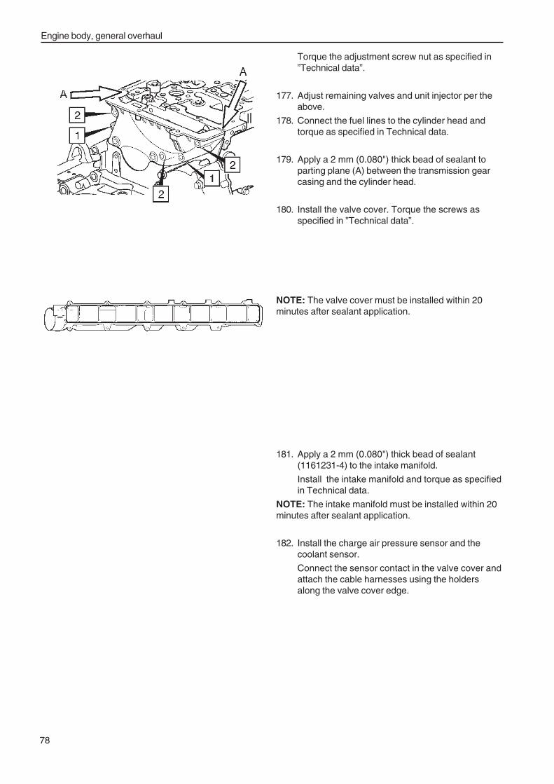
Engine body, general overhaul
78
Torque the adjustment screw nut as specified in”Technical data”.
177. Adjust remaining valves and unit injector per theabove.
178. Connect the fuel lines to the cylinder head andtorque as specified in Technical data.
179. Apply a 2 mm (0.080") thick bead of sealant toparting plane (A) between the transmission gearcasing and the cylinder head.
180. Install the valve cover. Torque the screws asspecified in ”Technical data”.
NOTE: The valve cover must be installed within 20minutes after sealant application.
181. Apply a 2 mm (0.080") thick bead of sealant(1161231-4) to the intake manifold.
Install the intake manifold and torque as specifiedin Technical data.
NOTE: The intake manifold must be installed within 20minutes after sealant application.
182. Install the charge air pressure sensor and thecoolant sensor.
Connect the sensor contact in the valve cover andattach the cable harnesses using the holdersalong the valve cover edge.
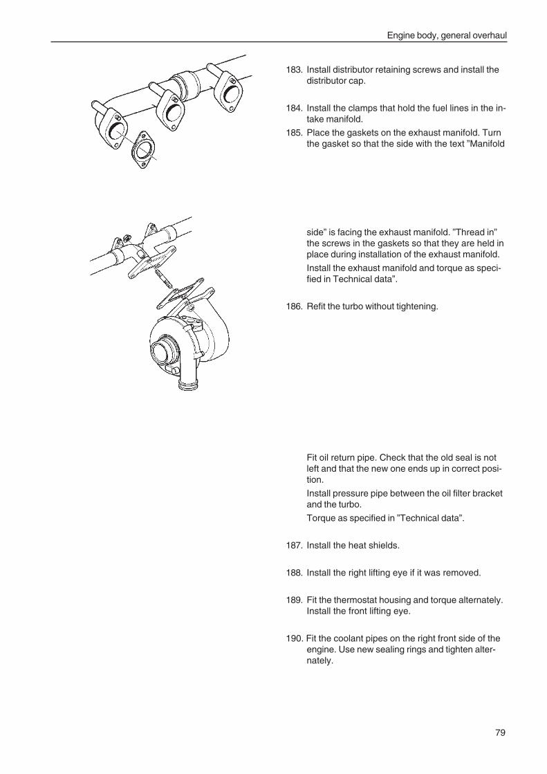
Engine body, general overhaul
79
183. Install distributor retaining screws and install thedistributor cap.
184. Install the clamps that hold the fuel lines in the in-take manifold.
185. Place the gaskets on the exhaust manifold. Turnthe gasket so that the side with the text ”Manifold
side” is facing the exhaust manifold. ”Thread in”the screws in the gaskets so that they are held inplace during installation of the exhaust manifold.
Install the exhaust manifold and torque as speci-fied in Technical data”.
186. Refit the turbo without tightening.
Fit oil return pipe. Check that the old seal is notleft and that the new one ends up in correct posi-tion.
Install pressure pipe between the oil filter bracketand the turbo.
Torque as specified in ”Technical data”.
187. Install the heat shields.
188. Install the right lifting eye if it was removed.
189. Fit the thermostat housing and torque alternately.Install the front lifting eye.
190. Fit the coolant pipes on the right front side of theengine. Use new sealing rings and tighten alter-nately.
Engine body, general overhaul
80
191. Remove fixture and replace the parts that were re-moved.
192. Install the drive belts, fan, alternator and tension-ing devices.
193. Install brackets for radiator fan safety cover orscreen. Install the shields.
194. Install safety cover above alternator
195. Install the pipe between charge air cooler and inletpipe.
196. Install the crankcase ventilation pipe and any ex-tra oil separator.
197. Place a new insert in the air filter housing and in-stall it with brackets and the pipe between the airfilter housing and the turbo.
198. Install the pipe between the turbo and the chargeair cooler.
199. Install muffler with brackets. Connect the exhaustpipe to the turbo.
200. Install heat shield above the turbo, if any.
201. Install belt shield on the right-hand side of engine,if any. Install the hoses to expansion tank and ra-diator.
202. Replace oil filter. Add engine oil, see “Engine oil,replacing”.
203. Replace coolant filter. Top up with coolant, see“Coolant, filling”.
204. Replace fuel filter. Vent the fuel system, see “FuelSystem, bleeding”.
205. Start the engine and let it run until it reaches nor-mal operating temperature. Let it idle another 5-10minutes. When the idle is even, the cylinder bal-
ancing system has set the correct amount of fuelfor the unit injectors.
NOTE: Do not connect any power consuming device(such as power outlet) while cylinder balancing is un-derway.
Check that there is no fuel leakage.
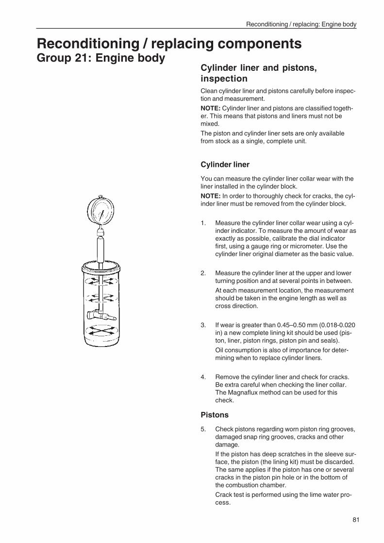
81
Reconditioning / replacing: Engine body
Reconditioning / replacing componentsGroup 21: Engine body
Cylinder liner and pistons,inspectionClean cylinder liner and pistons carefully before inspec-tion and measurement.
NOTE: Cylinder liner and pistons are classified togeth-er. This means that pistons and liners must not bemixed.
The piston and cylinder liner sets are only availablefrom stock as a single, complete unit.
Cylinder liner
You can measure the cylinder liner collar wear with theliner installed in the cylinder block.
NOTE: In order to thoroughly check for cracks, the cyl-inder liner must be removed from the cylinder block.
1. Measure the cylinder liner collar wear using a cyl-inder indicator. To measure the amount of wear asexactly as possible, calibrate the dial indicatorfirst, using a gauge ring or micrometer. Use thecylinder liner original diameter as the basic value.
2. Measure the cylinder liner at the upper and lowerturning position and at several points in between.
At each measurement location, the measurementshould be taken in the engine length as well ascross direction.
3. If wear is greater than 0.45–0.50 mm (0.018-0.020in) a new complete lining kit should be used (pis-ton, liner, piston rings, piston pin and seals).
Oil consumption is also of importance for deter-mining when to replace cylinder liners.
4. Remove the cylinder liner and check for cracks.Be extra careful when checking the liner collar.The Magnaflux method can be used for thischeck.
Pistons
5. Check pistons regarding worn piston ring grooves,damaged snap ring grooves, cracks and otherdamage.
If the piston has deep scratches in the sleeve sur-face, the piston (the lining kit) must be discarded.The same applies if the piston has one or severalcracks in the piston pin hole or in the bottom ofthe combustion chamber.
Crack test is performed using the lime water pro-cess.
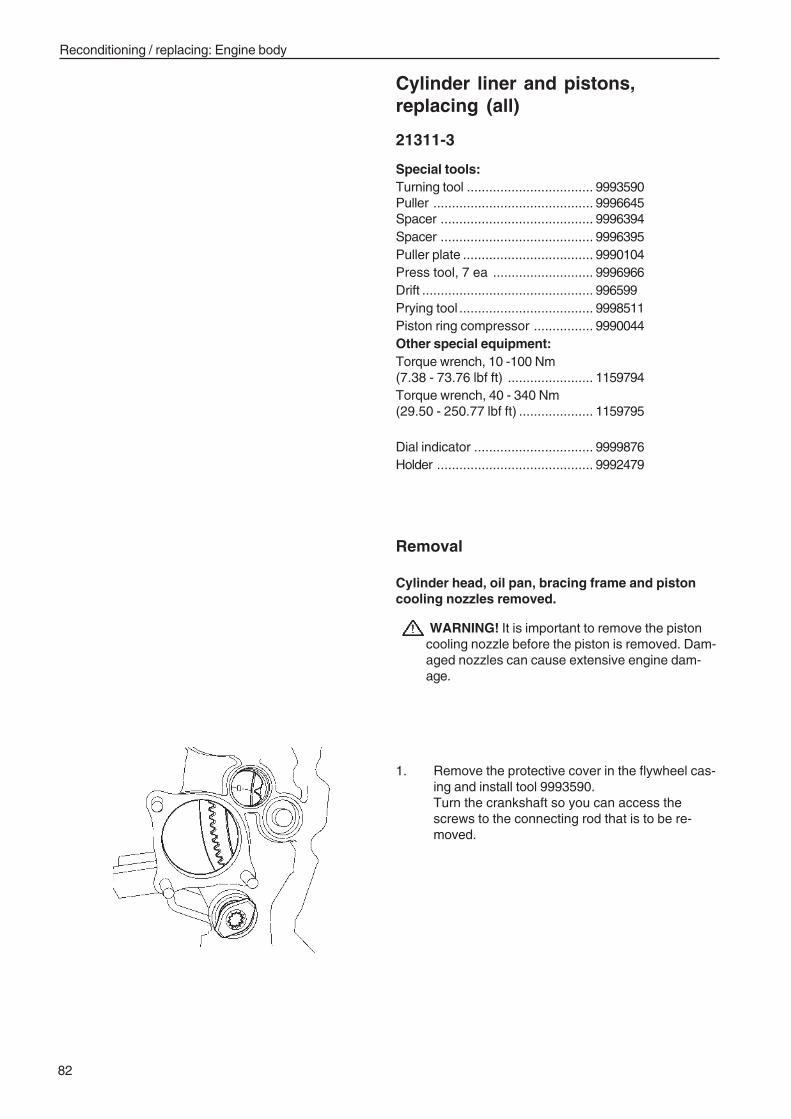
82
Reconditioning / replacing: Engine body
Cylinder liner and pistons,replacing (all)
21311-3
Special tools:Turning tool .................................. 9993590Puller ........................................... 9996645Spacer ......................................... 9996394Spacer ......................................... 9996395Puller plate ................................... 9990104Press tool, 7 ea ........................... 9996966Drift .............................................. 996599Prying tool .................................... 9998511Piston ring compressor ................ 9990044Other special equipment:Torque wrench, 10 -100 Nm(7.38 - 73.76 lbf ft) ....................... 1159794Torque wrench, 40 - 340 Nm(29.50 - 250.77 lbf ft) .................... 1159795
Dial indicator ................................ 9999876Holder .......................................... 9992479
Removal
Cylinder head, oil pan, bracing frame and pistoncooling nozzles removed.
WARNING! It is important to remove the pistoncooling nozzle before the piston is removed. Dam-aged nozzles can cause extensive engine dam-age.
1. Remove the protective cover in the flywheel cas-ing and install tool 9993590.Turn the crankshaft so you can access thescrews to the connecting rod that is to be re-moved.
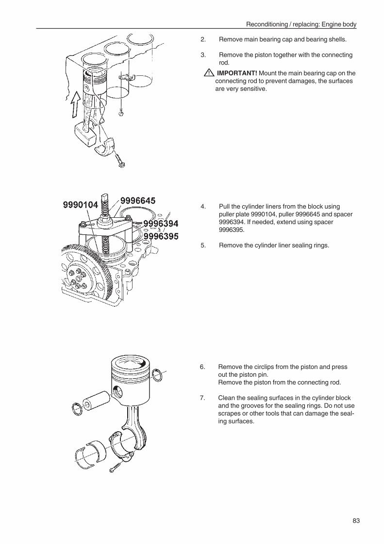
83
Reconditioning / replacing: Engine body
2. Remove main bearing cap and bearing shells.
3. Remove the piston together with the connectingrod.
IMPORTANT! Mount the main bearing cap on theconnecting rod to prevent damages, the surfacesare very sensitive.
4. Pull the cylinder liners from the block usingpuller plate 9990104, puller 9996645 and spacer9996394. If needed, extend using spacer9996395.
5. Remove the cylinder liner sealing rings.
6. Remove the circlips from the piston and pressout the piston pin.Remove the piston from the connecting rod.
7. Clean the sealing surfaces in the cylinder blockand the grooves for the sealing rings. Do not usescrapes or other tools that can damage the seal-ing surfaces.
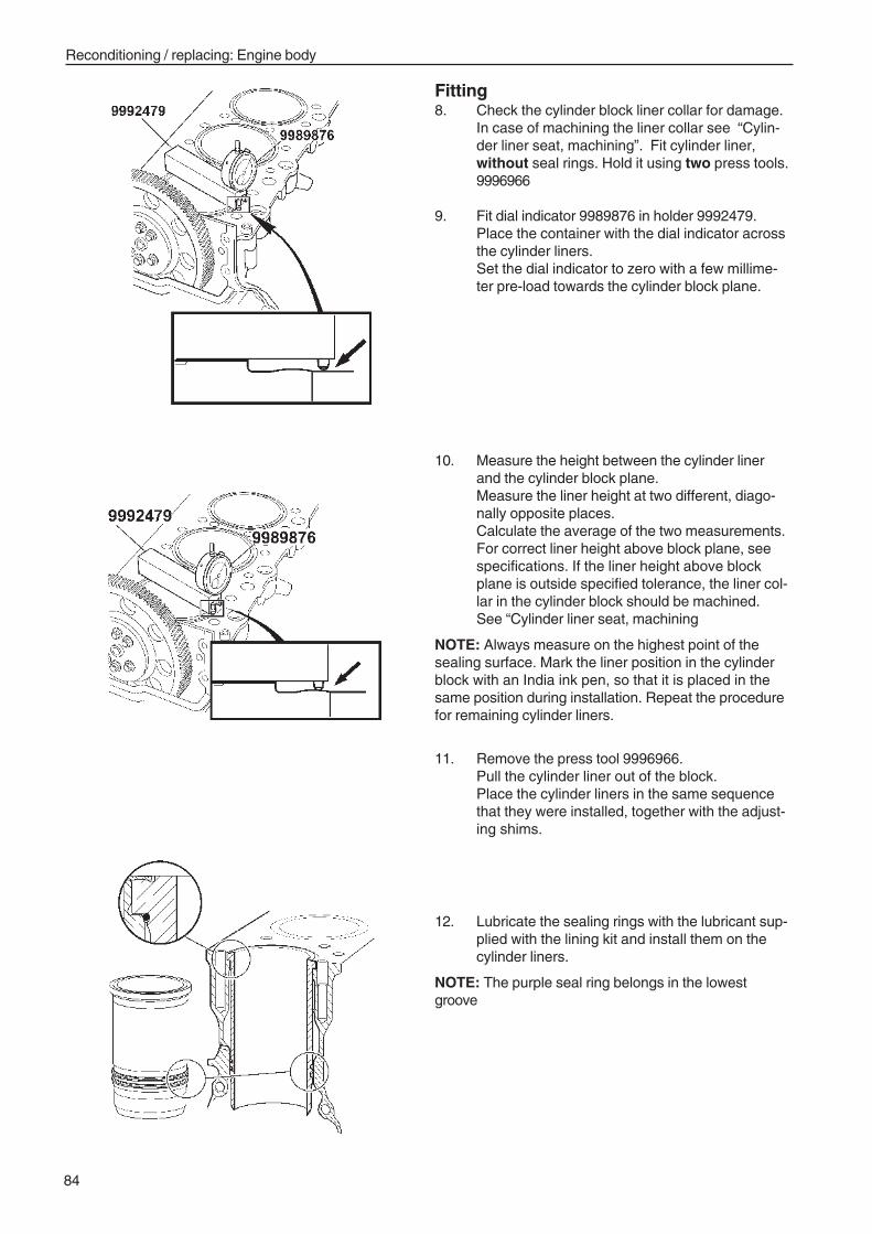
84
Reconditioning / replacing: Engine body
Fitting8. Check the cylinder block liner collar for damage.
In case of machining the liner collar see “Cylin-der liner seat, machining”. Fit cylinder liner,without seal rings. Hold it using two press tools.9996966
9. Fit dial indicator 9989876 in holder 9992479.Place the container with the dial indicator acrossthe cylinder liners.Set the dial indicator to zero with a few millime-ter pre-load towards the cylinder block plane.
10. Measure the height between the cylinder linerand the cylinder block plane.Measure the liner height at two different, diago-nally opposite places.Calculate the average of the two measurements.For correct liner height above block plane, seespecifications. If the liner height above blockplane is outside specified tolerance, the liner col-lar in the cylinder block should be machined.See “Cylinder liner seat, machining
NOTE: Always measure on the highest point of thesealing surface. Mark the liner position in the cylinderblock with an India ink pen, so that it is placed in thesame position during installation. Repeat the procedurefor remaining cylinder liners.
11. Remove the press tool 9996966.Pull the cylinder liner out of the block.Place the cylinder liners in the same sequencethat they were installed, together with the adjust-ing shims.
12. Lubricate the sealing rings with the lubricant sup-plied with the lining kit and install them on thecylinder liners.
NOTE: The purple seal ring belongs in the lowestgroove
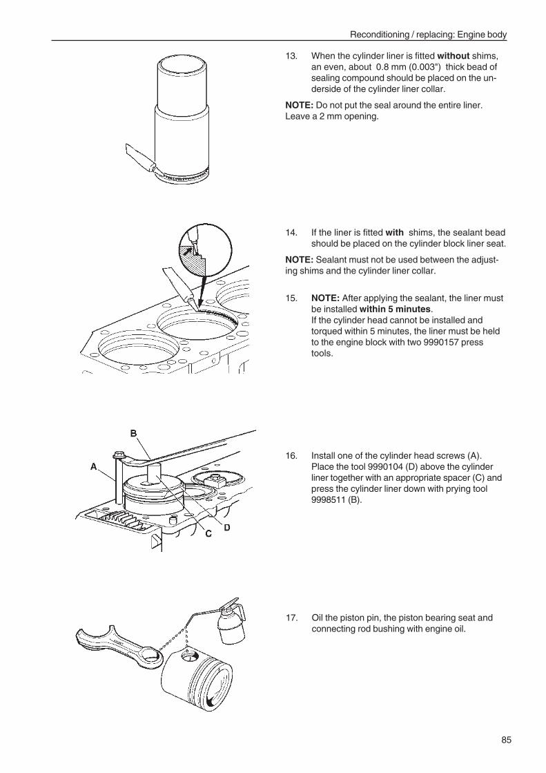
85
Reconditioning / replacing: Engine body
16. Install one of the cylinder head screws (A).Place the tool 9990104 (D) above the cylinderliner together with an appropriate spacer (C) andpress the cylinder liner down with prying tool9998511 (B).
13. When the cylinder liner is fitted without shims,an even, about 0.8 mm (0.003") thick bead ofsealing compound should be placed on the un-derside of the cylinder liner collar.
NOTE: Do not put the seal around the entire liner.Leave a 2 mm opening.
14. If the liner is fitted with shims, the sealant beadshould be placed on the cylinder block liner seat.
NOTE: Sealant must not be used between the adjust-ing shims and the cylinder liner collar.
15. NOTE: After applying the sealant, the liner mustbe installed within 5 minutes.If the cylinder head cannot be installed andtorqued within 5 minutes, the liner must be heldto the engine block with two 9990157 presstools.
17. Oil the piston pin, the piston bearing seat andconnecting rod bushing with engine oil.
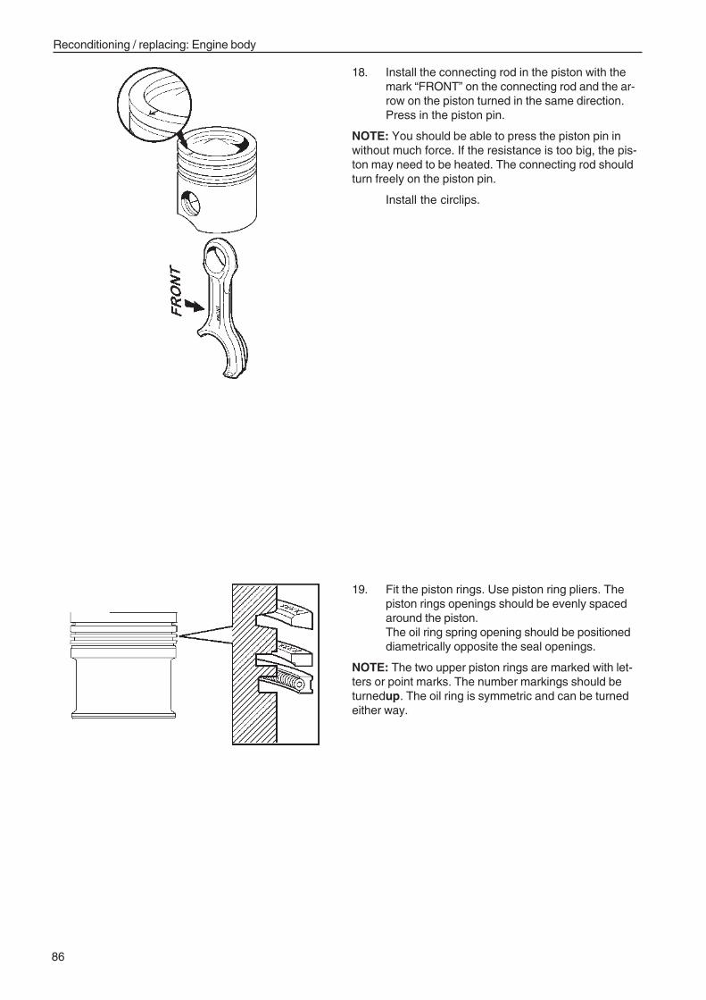
86
Reconditioning / replacing: Engine body
18. Install the connecting rod in the piston with themark “FRONT” on the connecting rod and the ar-row on the piston turned in the same direction.Press in the piston pin.
NOTE: You should be able to press the piston pin inwithout much force. If the resistance is too big, the pis-ton may need to be heated. The connecting rod shouldturn freely on the piston pin.
Install the circlips.
19. Fit the piston rings. Use piston ring pliers. Thepiston rings openings should be evenly spacedaround the piston.The oil ring spring opening should be positioneddiametrically opposite the seal openings.
NOTE: The two upper piston rings are marked with let-ters or point marks. The number markings should beturnedup. The oil ring is symmetric and can be turnedeither way.
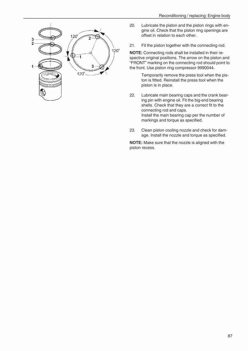
87
Reconditioning / replacing: Engine body
20. Lubricate the piston and the piston rings with en-gine oil. Check that the piston ring openings areoffset in relation to each other.
21. Fit the piston together with the connecting rod.
NOTE: Connecting rods shall be installed in their re-spective original positions. The arrow on the piston and“FRONT” marking on the connecting rod should point tothe front. Use piston ring compressor 9990044.
Temporarily remove the press tool when the pis-ton is fitted. Reinstall the press tool when thepiston is in place.
22. Lubricate main bearing caps and the crank bear-ing pin with engine oil. Fit the big-end bearingshells. Check that they are a correct fit to theconnecting rod and caps.Install the main bearing cap per the number ofmarkings and torque as specified.
23. Clean piston cooling nozzle and check for dam-age. Install the nozzle and torque as specified.
NOTE: Make sure that the nozzle is aligned with thepiston recess.
88
Reconditioning / replacing: Engine body
Crankshaft, inspectionThe crankshaft has been induction-hardened.
Inspect the crankshaft thoroughly to avoid unnecessaryreconditioning.
To determine reconditioning requirements, the followingapplies:
1. Thoroughly clean the crankshaft.
Measure the bearing journals for out-of roundness,wear and taper. See ”Technical data”.
2. Investigate whether surface damage occurs onthe bearing races. If the surface layer is damaged,the shaft should be reground.
3. The crankshaft should be placed on either a pairof V-blocks, under 1st and 7th main bearing jour-nals. Alternatively, hold the crankshaft betweenstocks.
4. Measure crankshaft alignment (throw) on the 4thmain bearing.
Max. allowed values, see ”Technical data”.
NOTE: Straightening of the crankshaft is not allowed.
4. Check for cracks before and after any grinding. Tocheck, use a magnetic powder test, i.e. fluores-cent powder which can be seen under ultravioletlight.
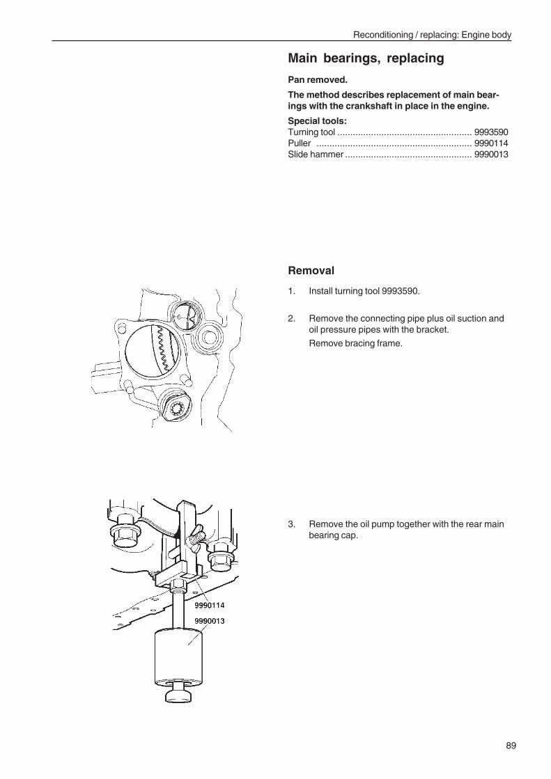
89
Reconditioning / replacing: Engine body
Main bearings, replacing
Pan removed.
The method describes replacement of main bear-ings with the crankshaft in place in the engine.
Special tools:Turning tool .................................................... 9993590Puller ............................................................ 9990114Slide hammer ................................................. 9990013
3. Remove the oil pump together with the rear mainbearing cap.
Removal
1. Install turning tool 9993590.
2. Remove the connecting pipe plus oil suction andoil pressure pipes with the bracket.
Remove bracing frame.
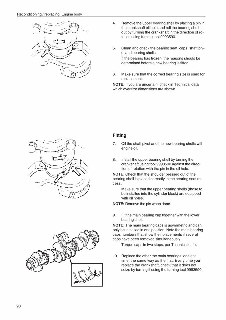
90
Reconditioning / replacing: Engine body
4. Remove the upper bearing shell by placing a pin inthe crankshaft oil hole and roll the bearing shellout by turning the crankshaft in the direction of ro-tation using turning tool 9993590.
5. Clean and check the bearing seat, caps, shaft piv-ot and bearing shells.
If the bearing has frozen, the reasons should bedetermined before a new bearing is fitted.
6. Make sure that the correct bearing size is used forreplacement.
NOTE: If you are uncertain, check in Technical datawhich oversize dimensions are shown.
Fitting
7. Oil the shaft pivot and the new bearing shells withengine oil.
8. Install the upper bearing shell by turning thecrankshaft using tool 9993590 against the direc-tion of rotation with the pin in the oil hole.
NOTE: Check that the shoulder pressed out of thebearing shell is placed correctly in the bearing seat re-cess.
Make sure that the upper bearing shells (those tobe installed into the cylinder block) are equippedwith oil holes.
NOTE: Remove the pin when done.
9. Fit the main bearing cap together with the lowerbearing shell.
NOTE: The main bearing caps is asymmetric and canonly be installed in one position. Note the main bearingcaps numbers that show their placements if severalcaps have been removed simultaneously.
Torque caps in two steps, per Technical data.
10. Replace the other the main bearings, one at atime, the same way as the first. Every time youreplace the crankshaft, check that it does notseize by turning it using the turning tool 9993590.
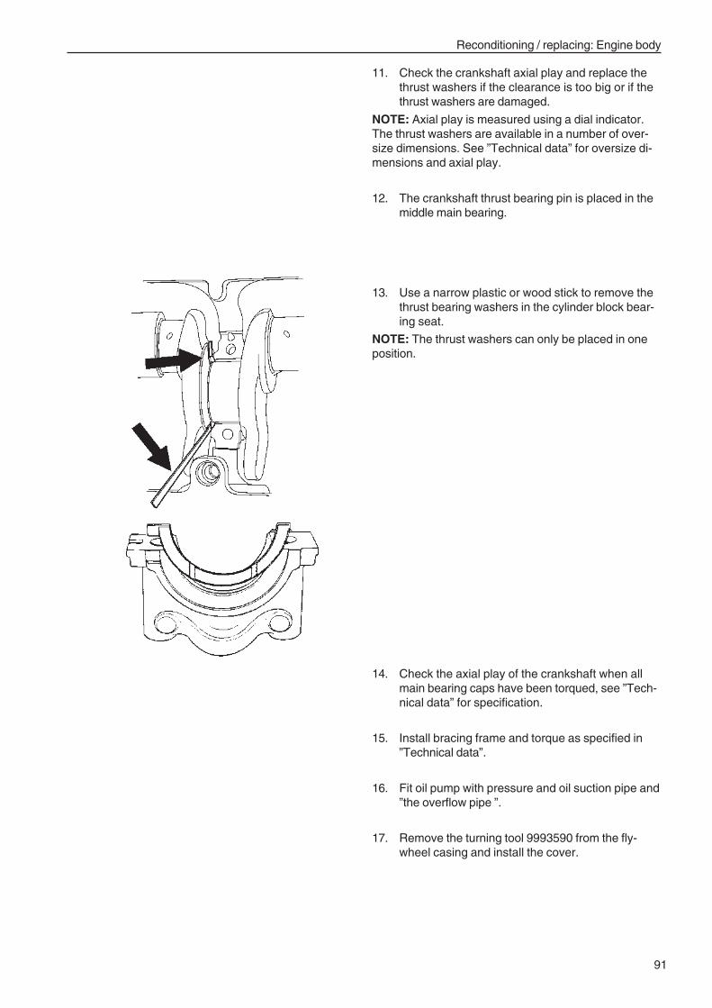
91
Reconditioning / replacing: Engine body
11. Check the crankshaft axial play and replace thethrust washers if the clearance is too big or if thethrust washers are damaged.
NOTE: Axial play is measured using a dial indicator.The thrust washers are available in a number of over-size dimensions. See ”Technical data” for oversize di-mensions and axial play.
12. The crankshaft thrust bearing pin is placed in themiddle main bearing.
13. Use a narrow plastic or wood stick to remove thethrust bearing washers in the cylinder block bear-ing seat.
NOTE: The thrust washers can only be placed in oneposition.
14. Check the axial play of the crankshaft when allmain bearing caps have been torqued, see ”Tech-nical data” for specification.
15. Install bracing frame and torque as specified in”Technical data”.
16. Fit oil pump with pressure and oil suction pipe and”the overflow pipe ”.
17. Remove the turning tool 9993590 from the fly-wheel casing and install the cover.
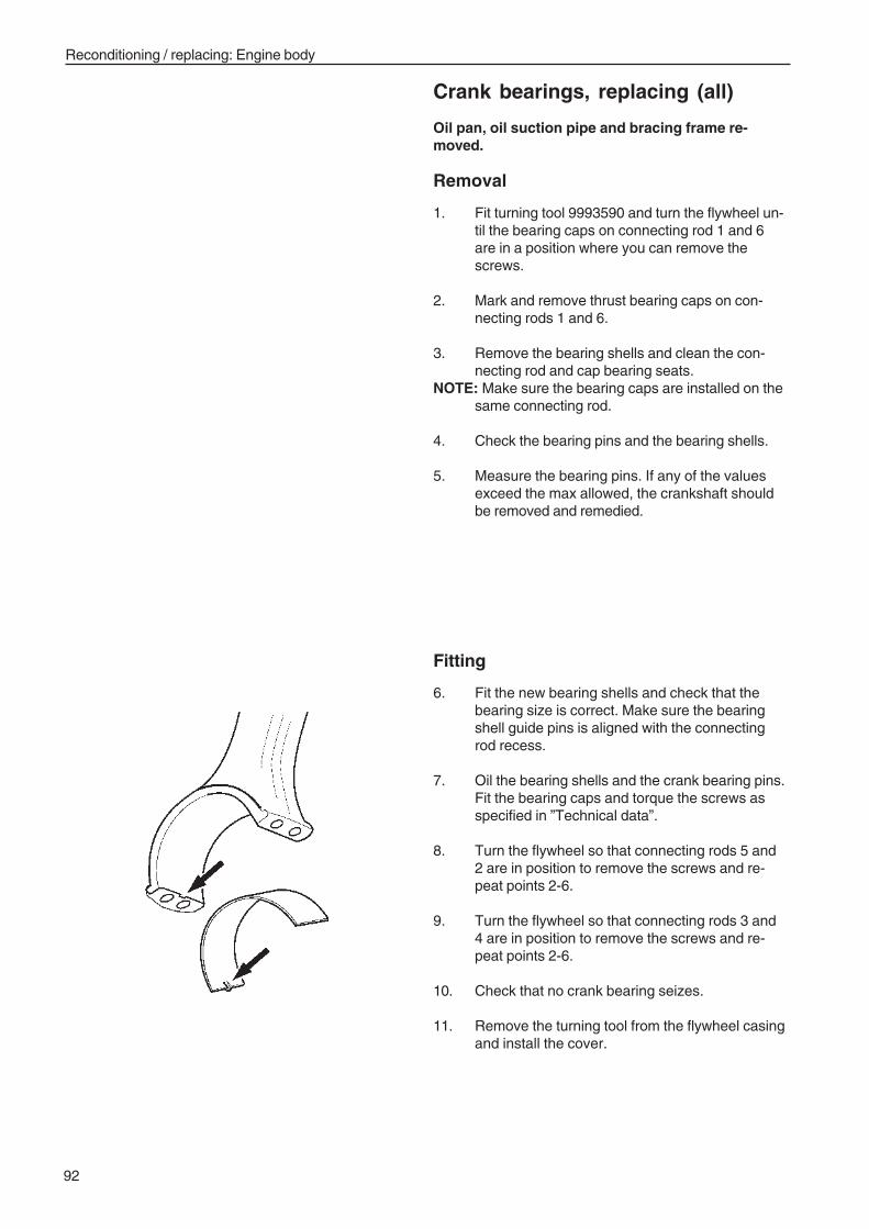
92
Reconditioning / replacing: Engine body
Crank bearings, replacing (all)
Oil pan, oil suction pipe and bracing frame re-moved.
Removal
1. Fit turning tool 9993590 and turn the flywheel un-til the bearing caps on connecting rod 1 and 6are in a position where you can remove thescrews.
2. Mark and remove thrust bearing caps on con-necting rods 1 and 6.
3. Remove the bearing shells and clean the con-necting rod and cap bearing seats.
NOTE: Make sure the bearing caps are installed on thesame connecting rod.
4. Check the bearing pins and the bearing shells.
5. Measure the bearing pins. If any of the valuesexceed the max allowed, the crankshaft shouldbe removed and remedied.
Fitting
6. Fit the new bearing shells and check that thebearing size is correct. Make sure the bearingshell guide pins is aligned with the connectingrod recess.
7. Oil the bearing shells and the crank bearing pins.Fit the bearing caps and torque the screws asspecified in ”Technical data”.
8. Turn the flywheel so that connecting rods 5 and2 are in position to remove the screws and re-peat points 2-6.
9. Turn the flywheel so that connecting rods 3 and4 are in position to remove the screws and re-peat points 2-6.
10. Check that no crank bearing seizes.
11. Remove the turning tool from the flywheel casingand install the cover.
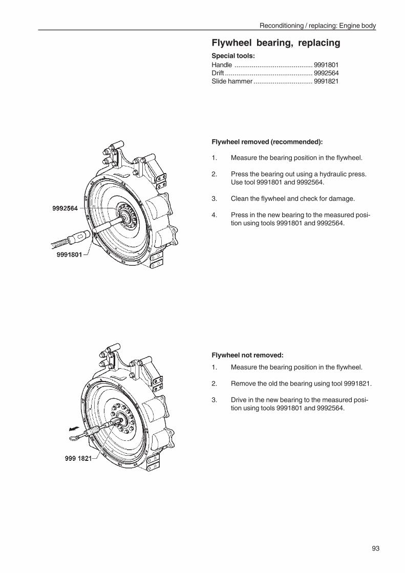
93
Reconditioning / replacing: Engine body
Flywheel bearing, replacingSpecial tools:Handle ......................................... 9991801Drift .............................................. 9992564Slide hammer ............................... 9991821
Flywheel removed (recommended):
1. Measure the bearing position in the flywheel.
2. Press the bearing out using a hydraulic press.Use tool 9991801 and 9992564.
3. Clean the flywheel and check for damage.
4. Press in the new bearing to the measured posi-tion using tools 9991801 and 9992564.
Flywheel not removed:
1. Measure the bearing position in the flywheel.
2. Remove the old the bearing using tool 9991821.
3. Drive in the new bearing to the measured posi-tion using tools 9991801 and 9992564.
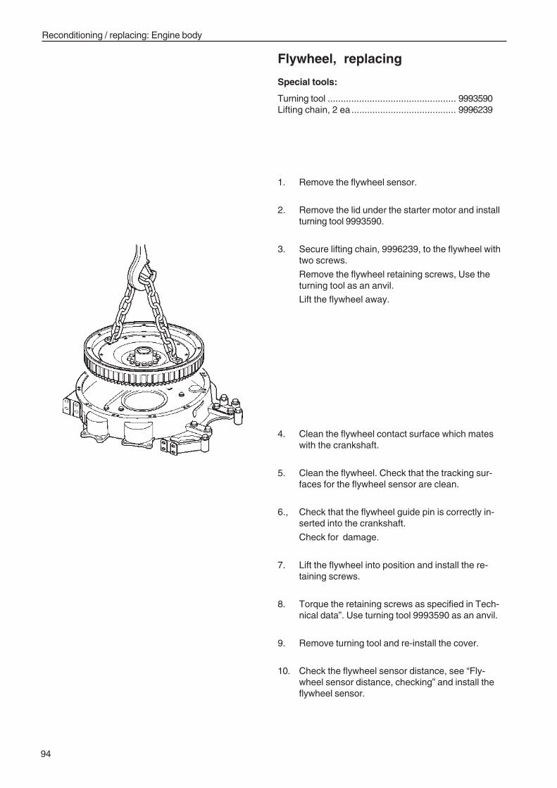
94
Reconditioning / replacing: Engine body
Flywheel, replacing
Special tools:
Turning tool ................................................. 9993590Lifting chain, 2 ea ........................................ 9996239
1. Remove the flywheel sensor.
2. Remove the lid under the starter motor and installturning tool 9993590.
3. Secure lifting chain, 9996239, to the flywheel withtwo screws.
Remove the flywheel retaining screws, Use theturning tool as an anvil.
Lift the flywheel away.
4. Clean the flywheel contact surface which mateswith the crankshaft.
5. Clean the flywheel. Check that the tracking sur-faces for the flywheel sensor are clean.
6., Check that the flywheel guide pin is correctly in-serted into the crankshaft.
Check for damage.
7. Lift the flywheel into position and install the re-taining screws.
8. Torque the retaining screws as specified in Tech-nical data”. Use turning tool 9993590 as an anvil.
9. Remove turning tool and re-install the cover.
10. Check the flywheel sensor distance, see “Fly-wheel sensor distance, checking” and install theflywheel sensor.
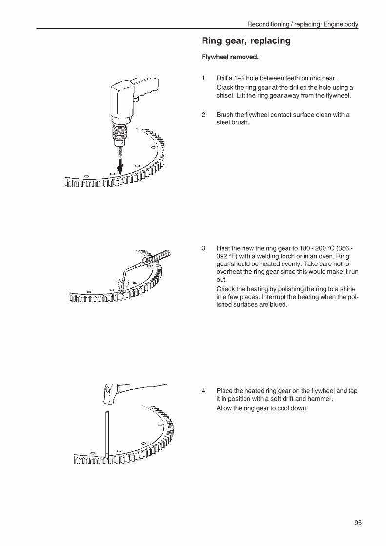
95
Reconditioning / replacing: Engine body
Ring gear, replacing
Flywheel removed.
1. Drill a 1–2 hole between teeth on ring gear.
Crack the ring gear at the drilled the hole using achisel. Lift the ring gear away from the flywheel.
2. Brush the flywheel contact surface clean with asteel brush.
3. Heat the new the ring gear to 180 - 200 °C (356 -392 °F) with a welding torch or in an oven. Ringgear should be heated evenly. Take care not tooverheat the ring gear since this would make it runout.
Check the heating by polishing the ring to a shinein a few places. Interrupt the heating when the pol-ished surfaces are blued.
4. Place the heated ring gear on the flywheel and tapit in position with a soft drift and hammer.
Allow the ring gear to cool down.
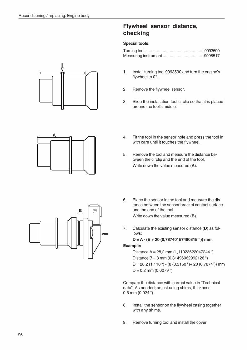
96
Reconditioning / replacing: Engine body
Flywheel sensor distance,checking
Special tools:
Turning tool .................................................. 9993590Measuring instrument .................................. 9998517
4. Fit the tool in the sensor hole and press the tool inwith care until it touches the flywheel.
5. Remove the tool and measure the distance be-tween the circlip and the end of the tool.
Write down the value measured (A).
6. Place the sensor in the tool and measure the dis-tance between the sensor bracket contact surfaceand the end of the tool.
Write down the value measured (B).
7. Calculate the existing sensor distance (D) as fol-lows:
D = A - (B + 20 (0,78740157480315 “)) mm.
Example:
Distance A = 28,2 mm (1,11023622047244 “)
Distance B = 8 mm (0,31496062992126 “)
D = 28,2 (1,110 “) - (8 (0,3150 ")+ 20 (0,7874”)) mm
D = 0,2 mm (0,0079 ”)
Compare the distance with correct value in ”Technicaldata”. As needed; adjust using shims, thickness0.6 mm (0.024 “).
8. Install the sensor on the flywheel casing togetherwith any shims.
9. Remove turning tool and install the cover.
1. Install turning tool 9993590 and turn the engine’sflywheel to 0°.
2. Remove the flywheel sensor.
3. Slide the installation tool circlip so that it is placedaround the tool’s middle.
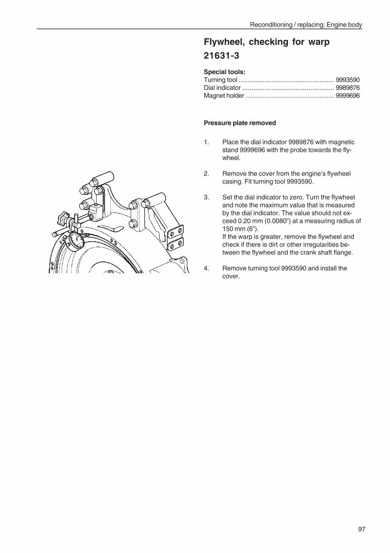
97
Reconditioning / replacing: Engine body
Flywheel, checking for warp
21631-3
Special tools:Turning tool .................................................... 9993590Dial indicator .................................................. 9989876Magnet holder ................................................ 9999696
Pressure plate removed
1. Place the dial indicator 9989876 with magneticstand 9999696 with the probe towards the fly-wheel.
2. Remove the cover from the engine’s flywheelcasing. Fit turning tool 9993590.
3. Set the dial indicator to zero. Turn the flywheeland note the maximum value that is measuredby the dial indicator. The value should not ex-ceed 0.20 mm (0.0080”) at a measuring radius of150 mm (6”).If the warp is greater, remove the flywheel andcheck if there is dirt or other irregularities be-tween the flywheel and the crank shaft flange.
4. Remove turning tool 9993590 and install thecover.
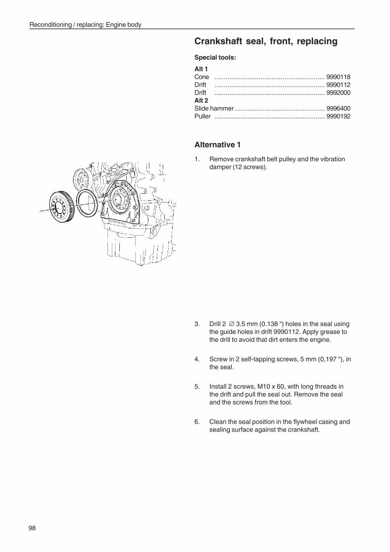
98
Reconditioning / replacing: Engine body
Crankshaft seal, front, replacing
Special tools:
Alt 1Cone ............................................................ 9990118Drift ............................................................ 9990112Drift ............................................................ 9992000Alt 2Slide hammer ................................................. 9996400Puller ............................................................ 9990192
Alternative 1
1. Remove crankshaft belt pulley and the vibrationdamper (12 screws).
3. Drill 2 ∅ 3.5 mm (0.138 “) holes in the seal usingthe guide holes in drift 9990112. Apply grease tothe drill to avoid that dirt enters the engine.
4. Screw in 2 self-tapping screws, 5 mm (0,197 “), inthe seal.
5. Install 2 screws, M10 x 60, with long threads inthe drift and pull the seal out. Remove the sealand the screws from the tool.
6. Clean the seal position in the flywheel casing andsealing surface against the crankshaft.
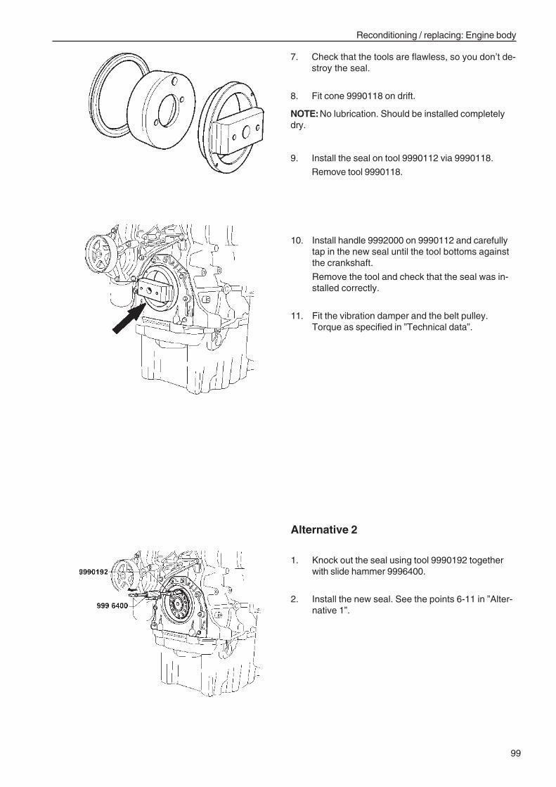
99
Reconditioning / replacing: Engine body
7. Check that the tools are flawless, so you don’t de-stroy the seal.
8. Fit cone 9990118 on drift.
NOTE:No lubrication. Should be installed completelydry.
9. Install the seal on tool 9990112 via 9990118.
Remove tool 9990118.
10. Install handle 9992000 on 9990112 and carefullytap in the new seal until the tool bottoms againstthe crankshaft.
Remove the tool and check that the seal was in-stalled correctly.
11. Fit the vibration damper and the belt pulley.Torque as specified in ”Technical data”.
Alternative 2
1. Knock out the seal using tool 9990192 togetherwith slide hammer 9996400.
2. Install the new seal. See the points 6-11 in ”Alter-native 1”.
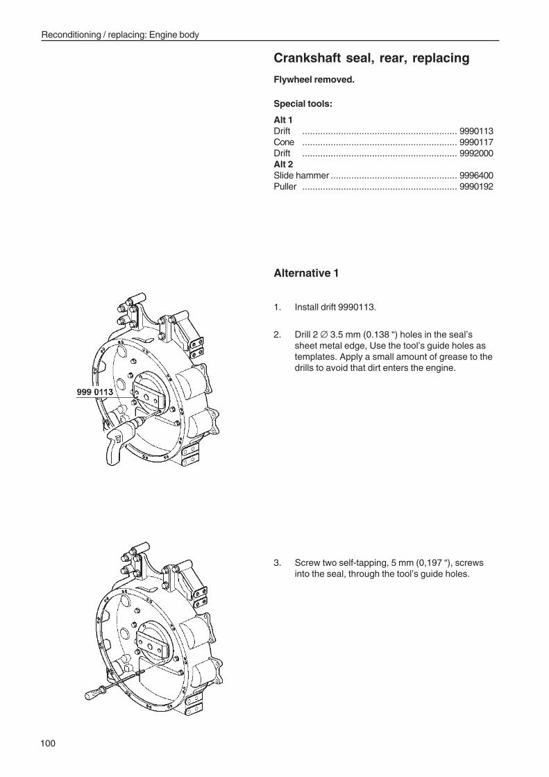
100
Reconditioning / replacing: Engine body
Crankshaft seal, rear, replacing
Flywheel removed.
Special tools:
Alt 1Drift ............................................................ 9990113Cone ............................................................ 9990117Drift ............................................................ 9992000Alt 2Slide hammer ................................................. 9996400Puller ............................................................ 9990192
Alternative 1
1. Install drift 9990113.
2. Drill 2 ∅ 3.5 mm (0.138 “) holes in the seal’ssheet metal edge, Use the tool’s guide holes astemplates. Apply a small amount of grease to thedrills to avoid that dirt enters the engine.
3. Screw two self-tapping, 5 mm (0,197 “), screwsinto the seal, through the tool’s guide holes.
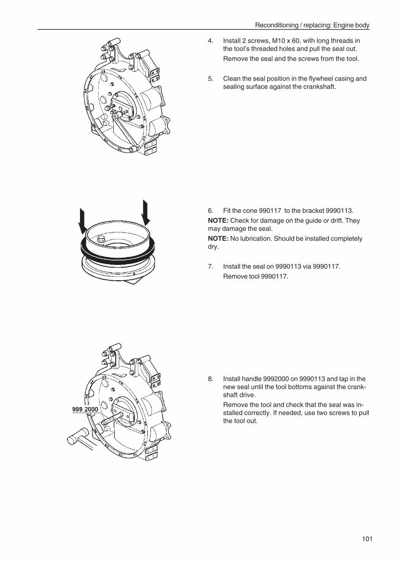
101
Reconditioning / replacing: Engine body
6. Fit the cone 990117 to the bracket 9990113.
NOTE: Check for damage on the guide or drift. Theymay damage the seal.
NOTE: No lubrication. Should be installed completelydry.
7. Install the seal on 9990113 via 9990117.
Remove tool 9990117.
4. Install 2 screws, M10 x 60, with long threads inthe tool’s threaded holes and pull the seal out.
Remove the seal and the screws from the tool.
5. Clean the seal position in the flywheel casing andsealing surface against the crankshaft.
8. Install handle 9992000 on 9990113 and tap in thenew seal until the tool bottoms against the crank-shaft drive.
Remove the tool and check that the seal was in-stalled correctly. If needed, use two screws to pullthe tool out.
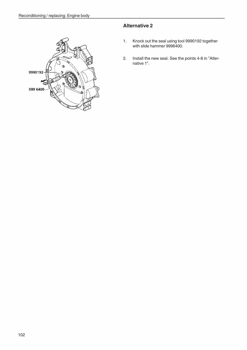
102
Reconditioning / replacing: Engine body
Alternative 2
1. Knock out the seal using tool 9990192 togetherwith slide hammer 9996400.
2. Install the new seal. See the points 4-8 in ”Alter-native 1”.
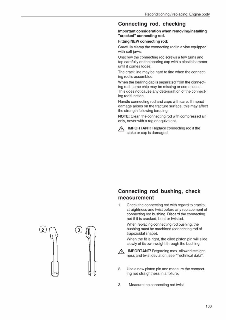
103
Reconditioning / replacing: Engine body
Connecting rod, checkingImportant consideration when removing/installing”cracked” connecting rod.Fitting NEW connecting rod:
Carefully clamp the connecting rod in a vise equippedwith soft jaws.
Unscrew the connecting rod screws a few turns andtap carefully on the bearing cap with a plastic hammeruntil it comes loose.
The crack line may be hard to find when the connect-ing rod is assembled.
When the bearing cap is separated from the connect-ing rod, some chip may be missing or come loose.This does not cause any deterioration of the connect-ing rod function.
Handle connecting rod and caps with care. If impactdamage arises on the fracture surface, this may affectthe strength following torquing.
NOTE: Clean the connecting rod with compressed aironly, never with a rag or equivalent.
IMPORTANT! Replace connecting rod if thestake or cap is damaged.
Connecting rod bushing, checkmeasurement1. Check the connecting rod with regard to cracks,
straightness and twist before any replacement ofconnecting rod bushing. Discard the connectingrod if it is cracked, bent or twisted.
When replacing connecting rod bushing, thebushing must be machined (connecting rod oftrapezoidal shape).
When the fit is right, the oiled piston pin will slideslowly of its own weight through the bushing.
IMPORTANT! Regarding max. allowed straight-ness and twist deviation, see ”Technical data”.
2. Use a new piston pin and measure the connect-ing rod straightness in a fixture.
3. Measure the connecting rod twist.
2 3
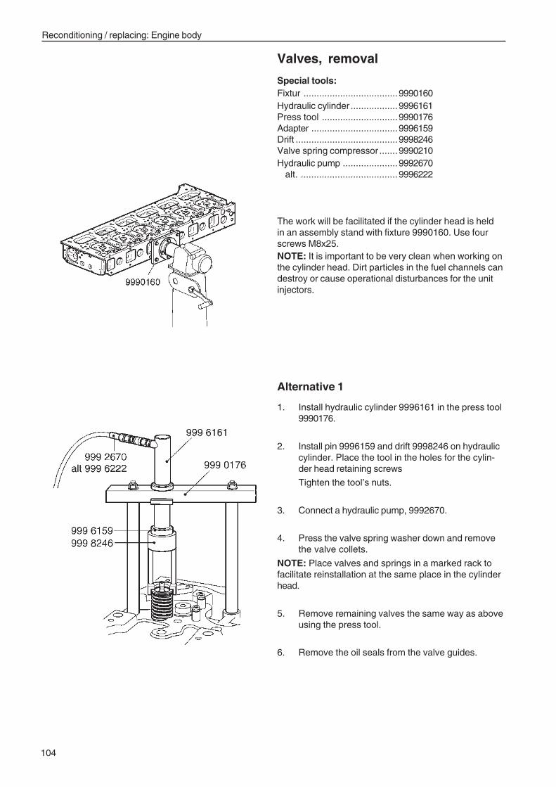
104
Reconditioning / replacing: Engine body
Valves, removal
Special tools:Fixtur ....................................9990160Hydraulic cylinder ..................9996161Press tool .............................9990176Adapter .................................9996159Drift .......................................9998246Valve spring compressor .......9990210Hydraulic pump .....................9992670
alt. .....................................9996222
The work will be facilitated if the cylinder head is heldin an assembly stand with fixture 9990160. Use fourscrews M8x25.NOTE: It is important to be very clean when working onthe cylinder head. Dirt particles in the fuel channels candestroy or cause operational disturbances for the unitinjectors.
Alternative 1
1. Install hydraulic cylinder 9996161 in the press tool9990176.
2. Install pin 9996159 and drift 9998246 on hydrauliccylinder. Place the tool in the holes for the cylin-der head retaining screws
Tighten the tool’s nuts.
3. Connect a hydraulic pump, 9992670.
4. Press the valve spring washer down and removethe valve collets.
NOTE: Place valves and springs in a marked rack tofacilitate reinstallation at the same place in the cylinderhead.
5. Remove remaining valves the same way as aboveusing the press tool.
6. Remove the oil seals from the valve guides.
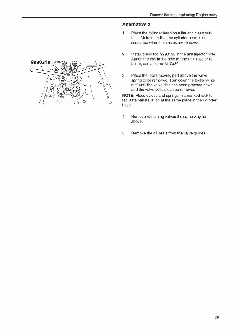
105
Reconditioning / replacing: Engine body
Alternative 2
1. Place the cylinder head on a flat and clean sur-face. Make sure that the cylinder head is notscratched when the valves are removed.
2. Install press tool 9990120 in the unit injector hole.Attach the tool in the hole for the unit injector re-tainer, use a screw M10x30.
3. Place the tool’s moving part above the valvespring to be removed. Turn down the tool’s ”wing-nut” until the valve disc has been pressed downand the valve collets can be removed.
NOTE: Place valves and springs in a marked rack tofacilitate reinstallation at the same place in the cylinderhead.
4. Remove remaining valves the same way asabove.
5 Remove the oil seals from the valve guides.
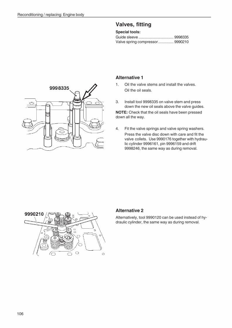
106
Reconditioning / replacing: Engine body
Valves, fittingSpecial tools:Guide sleeve ................................ 9998335Valve spring compressor .............. 9990210
Alternative 2Alternatively, tool 9990120 can be used instead of hy-draulic cylinder, the same way as during removal.
Alternative 11. Oil the valve stems and install the valves.
Oil the oil seals.
3. Install tool 9998335 on valve stem and pressdown the new oil seals above the valve guides.
NOTE: Check that the oil seals have been presseddown all the way.
4. Fit the valve springs and valve spring washers.
Press the valve disc down with care and fit thevalve collets. Use 9990176 together with hydrau-lic cylinder 9996161, pin 9996159 and drift9998246, the same way as during removal.
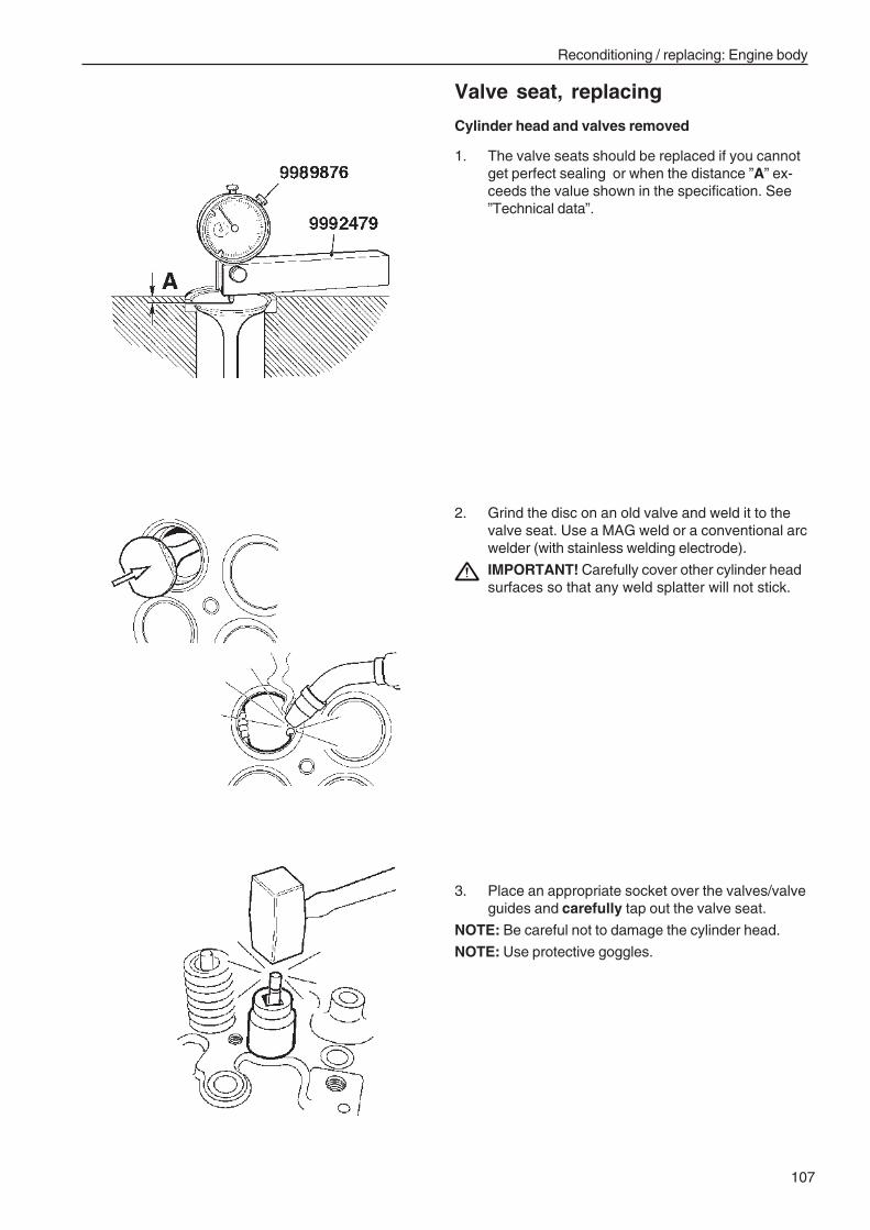
107
Reconditioning / replacing: Engine body
Valve seat, replacing
Cylinder head and valves removed
1. The valve seats should be replaced if you cannotget perfect sealing or when the distance ”A” ex-ceeds the value shown in the specification. See”Technical data”.
2. Grind the disc on an old valve and weld it to thevalve seat. Use a MAG weld or a conventional arcwelder (with stainless welding electrode).
IMPORTANT! Carefully cover other cylinder headsurfaces so that any weld splatter will not stick.
3. Place an appropriate socket over the valves/valveguides and carefully tap out the valve seat.
NOTE: Be careful not to damage the cylinder head.
NOTE: Use protective goggles.
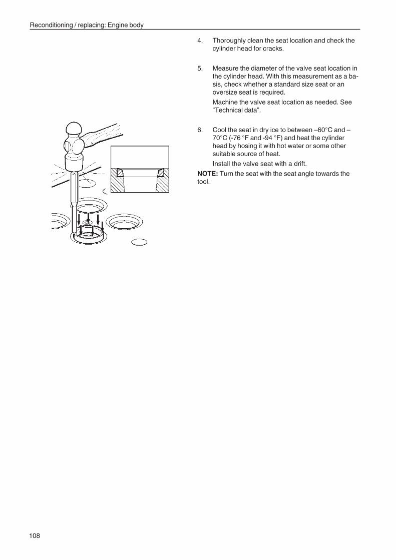
108
Reconditioning / replacing: Engine body
4. Thoroughly clean the seat location and check thecylinder head for cracks.
5. Measure the diameter of the valve seat location inthe cylinder head. With this measurement as a ba-sis, check whether a standard size seat or anoversize seat is required.
Machine the valve seat location as needed. See”Technical data”.
6. Cool the seat in dry ice to between –60°C and –70°C (-76 °F and -94 °F) and heat the cylinderhead by hosing it with hot water or some othersuitable source of heat.
Install the valve seat with a drift.
NOTE: Turn the seat with the seat angle towards thetool.
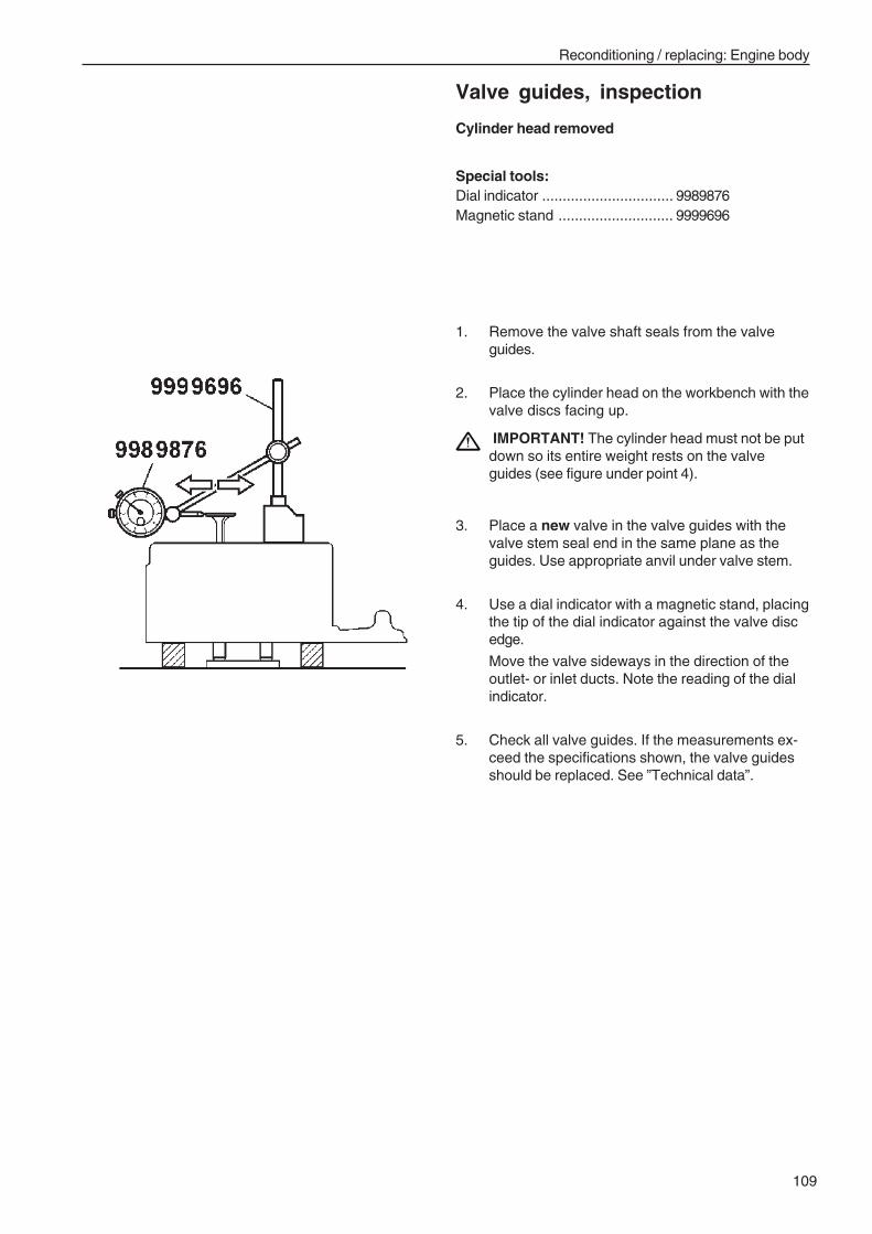
109
Reconditioning / replacing: Engine body
Valve guides, inspection
Cylinder head removed
Special tools:Dial indicator ................................ 9989876Magnetic stand ............................ 9999696
1. Remove the valve shaft seals from the valveguides.
2. Place the cylinder head on the workbench with thevalve discs facing up.
IMPORTANT! The cylinder head must not be putdown so its entire weight rests on the valveguides (see figure under point 4).
3. Place a new valve in the valve guides with thevalve stem seal end in the same plane as theguides. Use appropriate anvil under valve stem.
4. Use a dial indicator with a magnetic stand, placingthe tip of the dial indicator against the valve discedge.
Move the valve sideways in the direction of theoutlet- or inlet ducts. Note the reading of the dialindicator.
5. Check all valve guides. If the measurements ex-ceed the specifications shown, the valve guidesshould be replaced. See ”Technical data”.
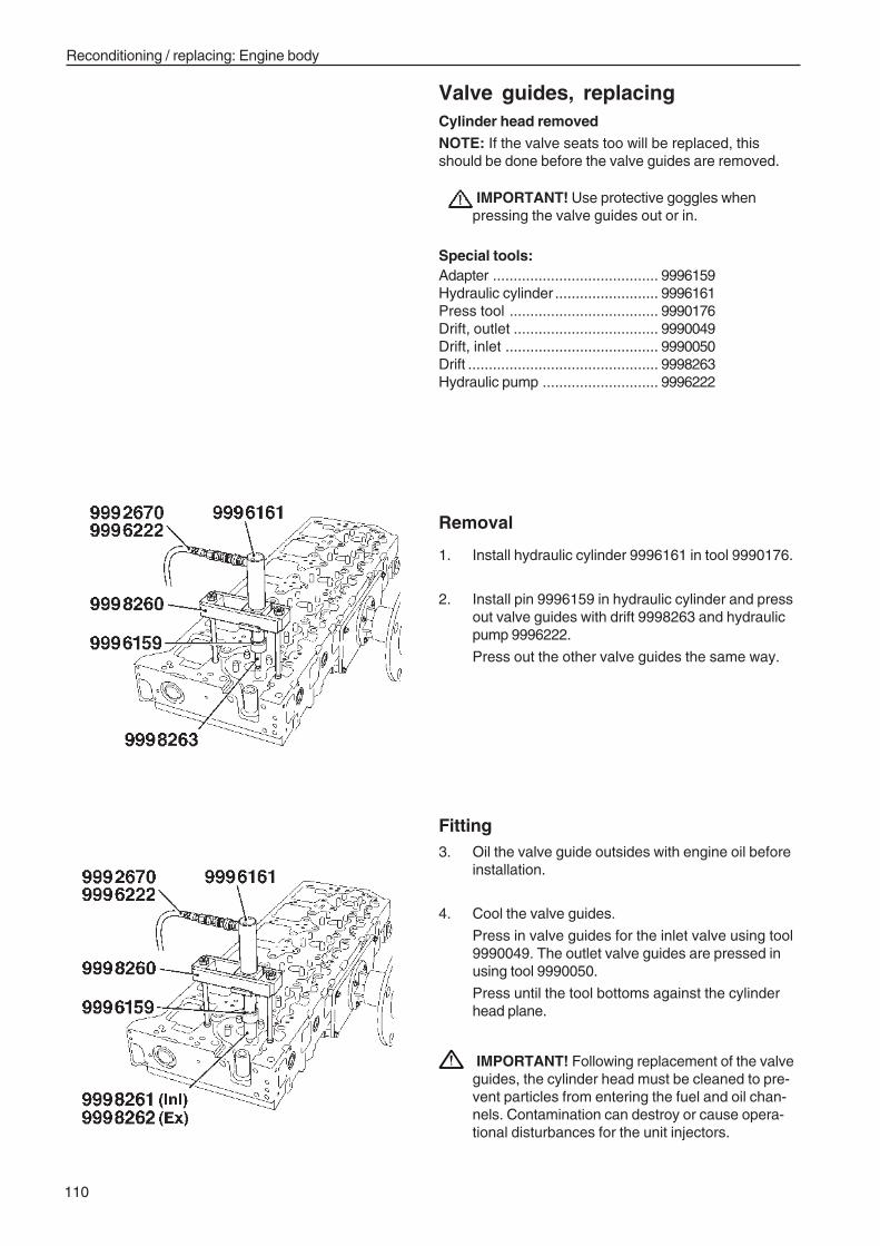
110
Reconditioning / replacing: Engine body
Valve guides, replacingCylinder head removedNOTE: If the valve seats too will be replaced, thisshould be done before the valve guides are removed.
IMPORTANT! Use protective goggles whenpressing the valve guides out or in.
Special tools:Adapter ........................................ 9996159Hydraulic cylinder ......................... 9996161Press tool .................................... 9990176Drift, outlet ................................... 9990049Drift, inlet ..................................... 9990050Drift .............................................. 9998263Hydraulic pump ............................ 9996222
Removal
1. Install hydraulic cylinder 9996161 in tool 9990176.
2. Install pin 9996159 in hydraulic cylinder and pressout valve guides with drift 9998263 and hydraulicpump 9996222.
Press out the other valve guides the same way.
Fitting3. Oil the valve guide outsides with engine oil before
installation.
4. Cool the valve guides.
Press in valve guides for the inlet valve using tool9990049. The outlet valve guides are pressed inusing tool 9990050.
Press until the tool bottoms against the cylinderhead plane.
IMPORTANT! Following replacement of the valveguides, the cylinder head must be cleaned to pre-vent particles from entering the fuel and oil chan-nels. Contamination can destroy or cause opera-tional disturbances for the unit injectors.
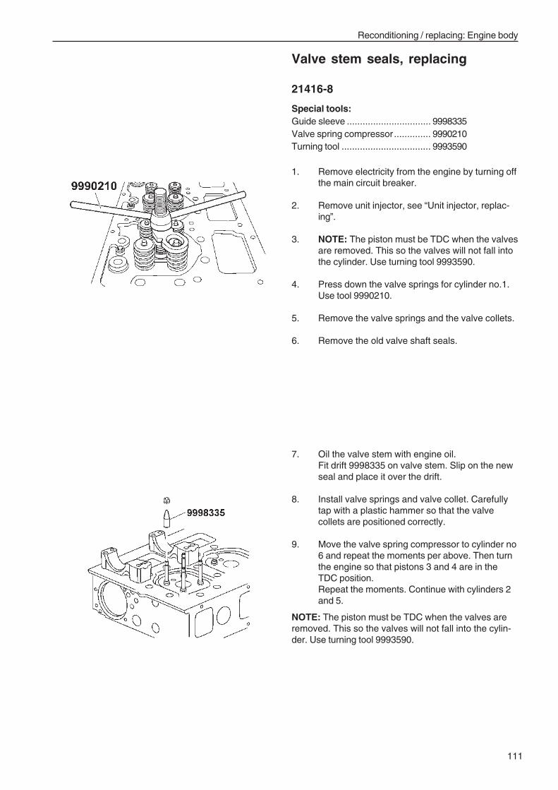
111
Reconditioning / replacing: Engine body
Valve stem seals, replacing
21416-8
Special tools:Guide sleeve ................................ 9998335Valve spring compressor .............. 9990210Turning tool .................................. 9993590
1. Remove electricity from the engine by turning offthe main circuit breaker.
2. Remove unit injector, see “Unit injector, replac-ing”.
3. NOTE: The piston must be TDC when the valvesare removed. This so the valves will not fall intothe cylinder. Use turning tool 9993590.
4. Press down the valve springs for cylinder no.1.Use tool 9990210.
5. Remove the valve springs and the valve collets.
6. Remove the old valve shaft seals.
7. Oil the valve stem with engine oil.Fit drift 9998335 on valve stem. Slip on the newseal and place it over the drift.
8. Install valve springs and valve collet. Carefullytap with a plastic hammer so that the valvecollets are positioned correctly.
9. Move the valve spring compressor to cylinder no6 and repeat the moments per above. Then turnthe engine so that pistons 3 and 4 are in theTDC position.Repeat the moments. Continue with cylinders 2and 5.
NOTE: The piston must be TDC when the valves areremoved. This so the valves will not fall into the cylin-der. Use turning tool 9993590.
112
Reconditioning / replacing: Engine body
10. Install unit injector, see “Unit injector, replacing”.
11. Adjust valves and unit injectors, see “Valves andunit injectors, adjusting”.
12. Bleed the fuel system. Check for function andleakage.
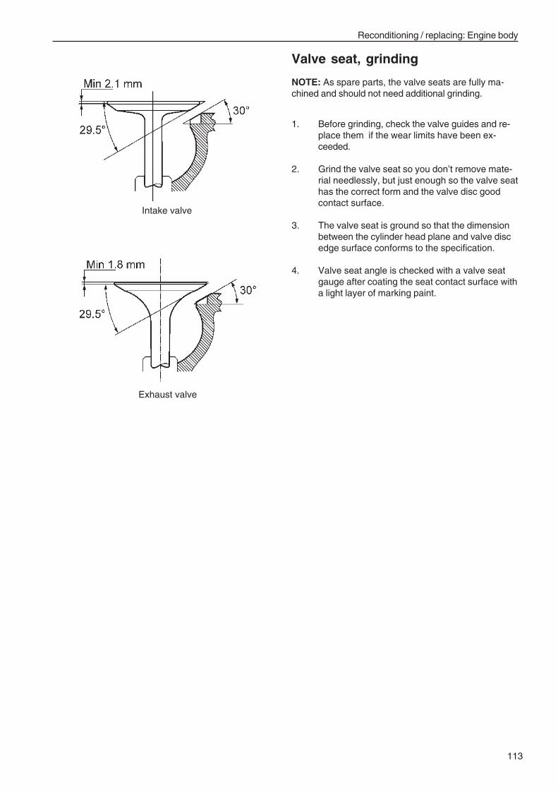
113
Reconditioning / replacing: Engine body
Valve seat, grinding
NOTE: As spare parts, the valve seats are fully ma-chined and should not need additional grinding.
1. Before grinding, check the valve guides and re-place them if the wear limits have been ex-ceeded.
2. Grind the valve seat so you don’t remove mate-rial needlessly, but just enough so the valve seathas the correct form and the valve disc goodcontact surface.
3. The valve seat is ground so that the dimensionbetween the cylinder head plane and valve discedge surface conforms to the specification.
4. Valve seat angle is checked with a valve seatgauge after coating the seat contact surface witha light layer of marking paint.
Intake valve
Exhaust valve
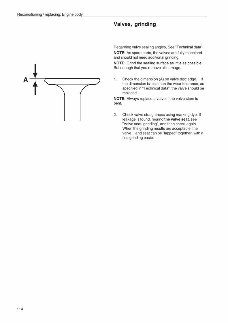
114
Reconditioning / replacing: Engine body
Valves, grinding
A
Regarding valve sealing angles, See ”Technical data”.
NOTE: As spare parts, the valves are fully machinedand should not need additional grinding.
NOTE: Grind the sealing surface as little as possible.But enough that you remove all damage.
1. Check the dimension (A) on valve disc edge. Ifthe dimension is less than the wear tolerance, asspecified in ”Technical data”, the valve should bereplaced.
NOTE: Always replace a valve if the valve stem isbent.
2. Check valve straightness using marking dye. Ifleakage is found, regrind the valve seat, see”Valve seat, grinding”, and then check again.When the grinding results are acceptable, thevalve and seat can be ”lapped” together, with afine grinding paste.
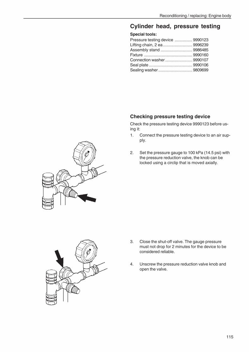
115
Reconditioning / replacing: Engine body
Cylinder head, pressure testingSpecial tools:Pressure testing device ............... 9990123Lifting chain, 2 ea......................... 9996239Assembly stand ........................... 9986485Fixture ......................................... 9990160Connection washer ....................... 9990107Seal plate ..................................... 9990106Sealing washer ............................. 9809699
Checking pressure testing deviceCheck the pressure testing device 9990123 before us-ing it:
1. Connect the pressure testing device to an air sup-ply.
2. Set the pressure gauge to 100 kPa (14.5 psi) withthe pressure reduction valve, the knob can belocked using a circlip that is moved axially.
3. Close the shut-off valve. The gauge pressuremust not drop for 2 minutes for the device to beconsidered reliable.
4. Unscrew the pressure reduction valve knob andopen the valve.
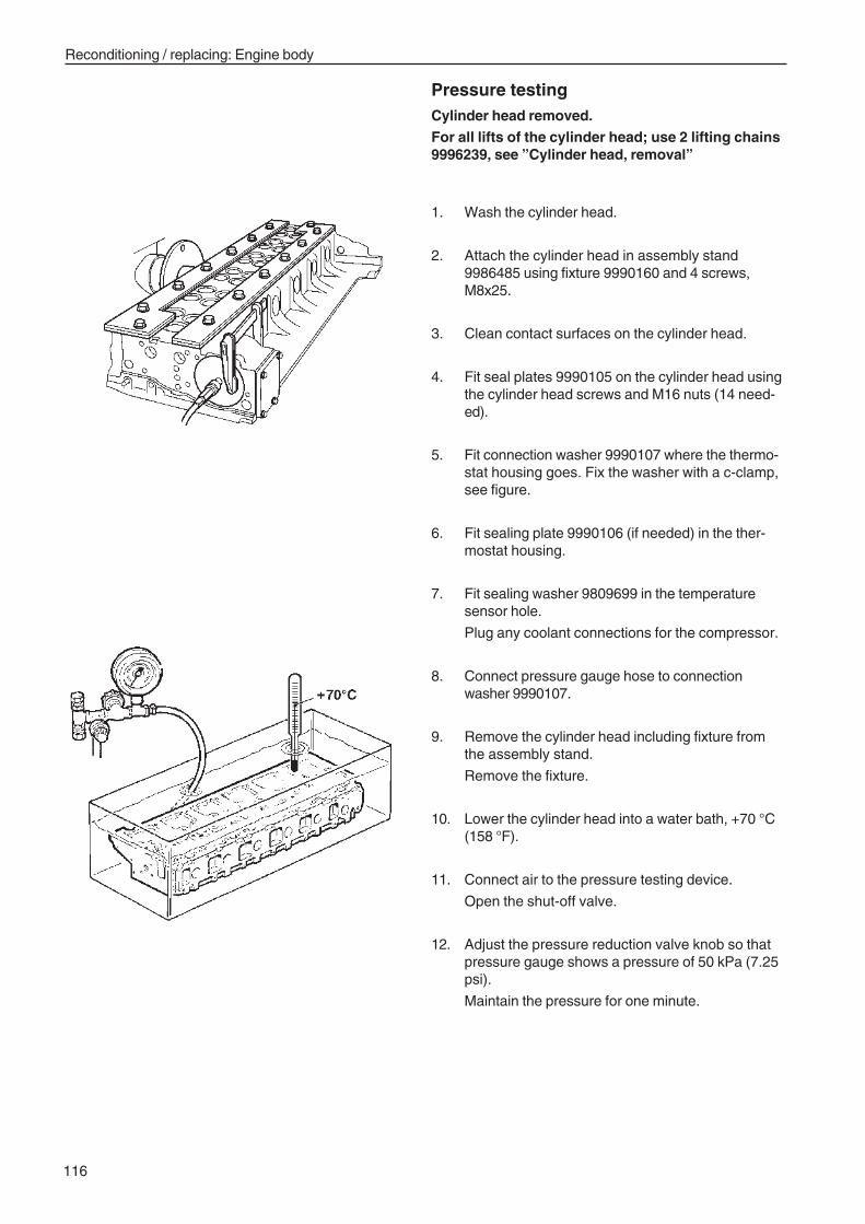
116
Reconditioning / replacing: Engine body
Pressure testingCylinder head removed.For all lifts of the cylinder head; use 2 lifting chains9996239, see ”Cylinder head, removal”
1. Wash the cylinder head.
2. Attach the cylinder head in assembly stand9986485 using fixture 9990160 and 4 screws,M8x25.
3. Clean contact surfaces on the cylinder head.
4. Fit seal plates 9990105 on the cylinder head usingthe cylinder head screws and M16 nuts (14 need-ed).
5. Fit connection washer 9990107 where the thermo-stat housing goes. Fix the washer with a c-clamp,see figure.
6. Fit sealing plate 9990106 (if needed) in the ther-mostat housing.
7. Fit sealing washer 9809699 in the temperaturesensor hole.
Plug any coolant connections for the compressor.
8. Connect pressure gauge hose to connectionwasher 9990107.
9. Remove the cylinder head including fixture fromthe assembly stand.
Remove the fixture.
10. Lower the cylinder head into a water bath, +70 °C(158 °F).
11. Connect air to the pressure testing device.
Open the shut-off valve.
12. Adjust the pressure reduction valve knob so thatpressure gauge shows a pressure of 50 kPa (7.25psi).
Maintain the pressure for one minute.
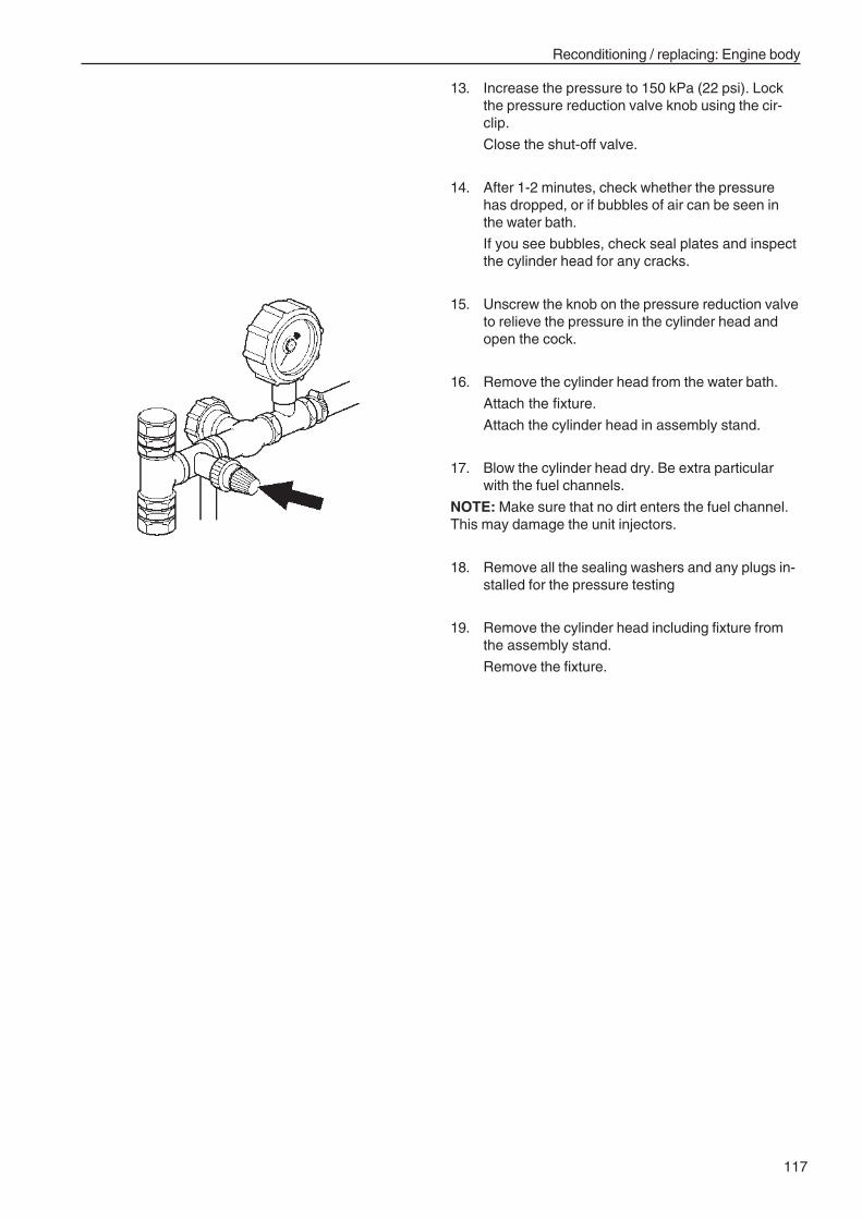
117
Reconditioning / replacing: Engine body
13. Increase the pressure to 150 kPa (22 psi). Lockthe pressure reduction valve knob using the cir-clip.
Close the shut-off valve.
14. After 1-2 minutes, check whether the pressurehas dropped, or if bubbles of air can be seen inthe water bath.
If you see bubbles, check seal plates and inspectthe cylinder head for any cracks.
15. Unscrew the knob on the pressure reduction valveto relieve the pressure in the cylinder head andopen the cock.
16. Remove the cylinder head from the water bath.
Attach the fixture.
Attach the cylinder head in assembly stand.
17. Blow the cylinder head dry. Be extra particularwith the fuel channels.
NOTE: Make sure that no dirt enters the fuel channel.This may damage the unit injectors.
18. Remove all the sealing washers and any plugs in-stalled for the pressure testing
19. Remove the cylinder head including fixture fromthe assembly stand.
Remove the fixture.
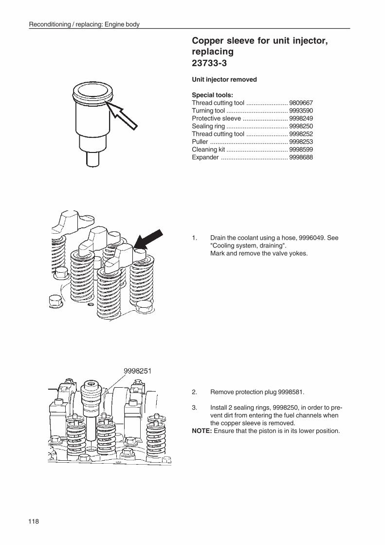
118
Reconditioning / replacing: Engine body
Copper sleeve for unit injector,replacing23733-3
Unit injector removed
Special tools:Thread cutting tool ....................... 9809667Turning tool .................................. 9993590Protective sleeve ......................... 9998249Sealing ring .................................. 9998250Thread cutting tool ....................... 9998252Puller ........................................... 9998253Cleaning kit .................................. 9998599Expander ..................................... 9998688
1. Drain the coolant using a hose, 9996049. See"Cooling system, draining".Mark and remove the valve yokes.
2. Remove protection plug 9998581.
3. Install 2 sealing rings, 9998250, in order to pre-vent dirt from entering the fuel channels whenthe copper sleeve is removed.
NOTE: Ensure that the piston is in its lower position.
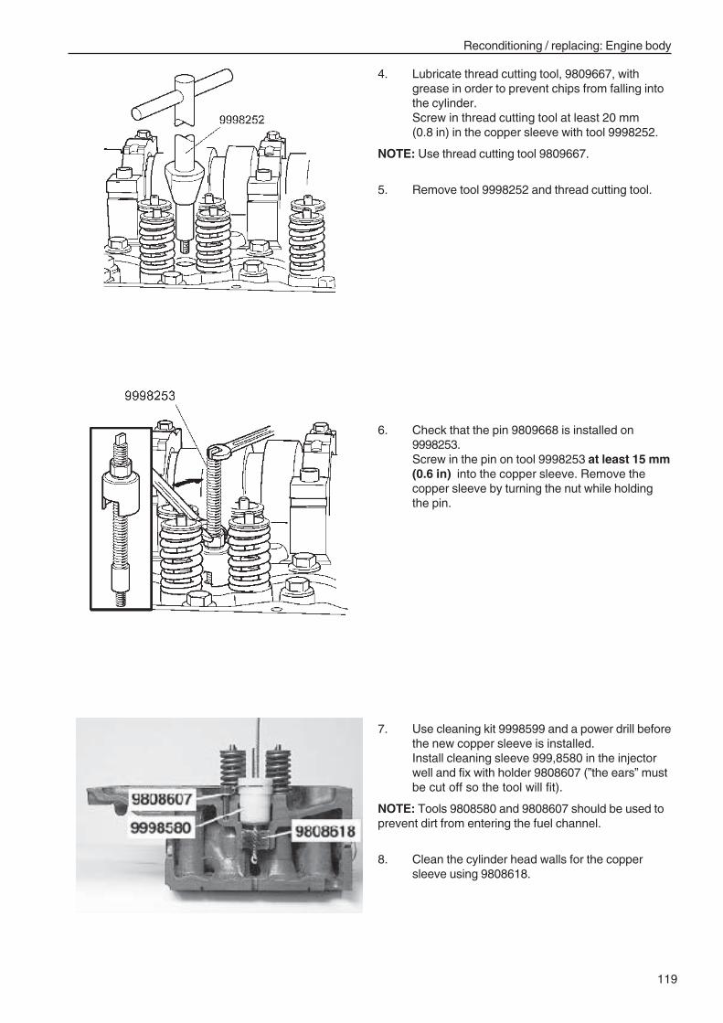
119
Reconditioning / replacing: Engine body
4. Lubricate thread cutting tool, 9809667, withgrease in order to prevent chips from falling intothe cylinder.Screw in thread cutting tool at least 20 mm(0.8 in) in the copper sleeve with tool 9998252.
NOTE: Use thread cutting tool 9809667.
5. Remove tool 9998252 and thread cutting tool.
6. Check that the pin 9809668 is installed on9998253.Screw in the pin on tool 9998253 at least 15 mm(0.6 in) into the copper sleeve. Remove thecopper sleeve by turning the nut while holdingthe pin.
7. Use cleaning kit 9998599 and a power drill beforethe new copper sleeve is installed.Install cleaning sleeve 999,8580 in the injectorwell and fix with holder 9808607 (”the ears” mustbe cut off so the tool will fit).
NOTE: Tools 9808580 and 9808607 should be used toprevent dirt from entering the fuel channel.
8. Clean the cylinder head walls for the coppersleeve using 9808618.
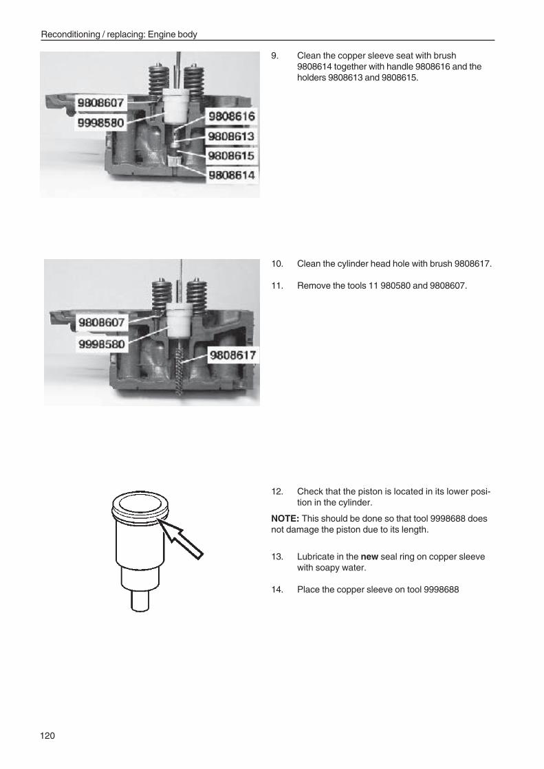
120
Reconditioning / replacing: Engine body
9. Clean the copper sleeve seat with brush9808614 together with handle 9808616 and theholders 9808613 and 9808615.
10. Clean the cylinder head hole with brush 9808617.
11. Remove the tools 11 980580 and 9808607.
12. Check that the piston is located in its lower posi-tion in the cylinder.
NOTE: This should be done so that tool 9998688 doesnot damage the piston due to its length.
13. Lubricate in the new seal ring on copper sleevewith soapy water.
14. Place the copper sleeve on tool 9998688
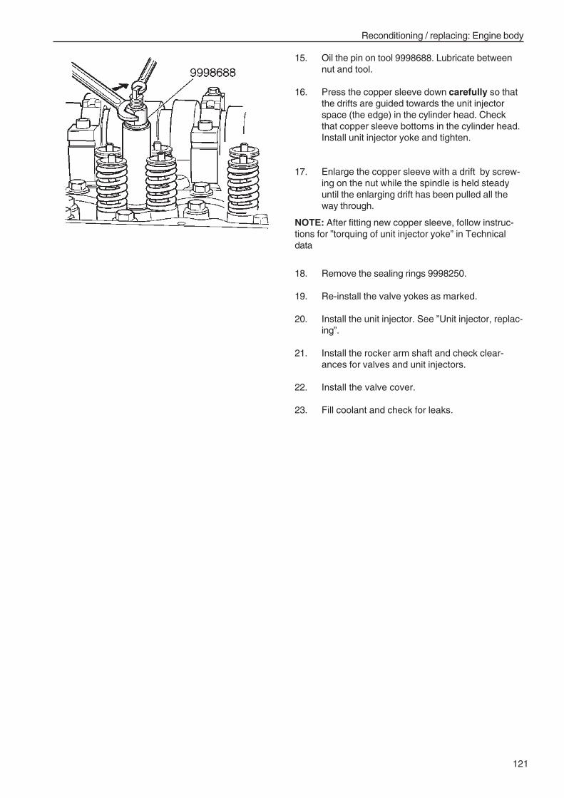
121
Reconditioning / replacing: Engine body
15. Oil the pin on tool 9998688. Lubricate betweennut and tool.
16. Press the copper sleeve down carefully so thatthe drifts are guided towards the unit injectorspace (the edge) in the cylinder head. Checkthat copper sleeve bottoms in the cylinder head.Install unit injector yoke and tighten.
17. Enlarge the copper sleeve with a drift by screw-ing on the nut while the spindle is held steadyuntil the enlarging drift has been pulled all theway through.
NOTE: After fitting new copper sleeve, follow instruc-tions for ”torquing of unit injector yoke” in Technicaldata
18. Remove the sealing rings 9998250.
19. Re-install the valve yokes as marked.
20. Install the unit injector. See ”Unit injector, replac-ing”.
21. Install the rocker arm shaft and check clear-ances for valves and unit injectors.
22. Install the valve cover.
23. Fill coolant and check for leaks.
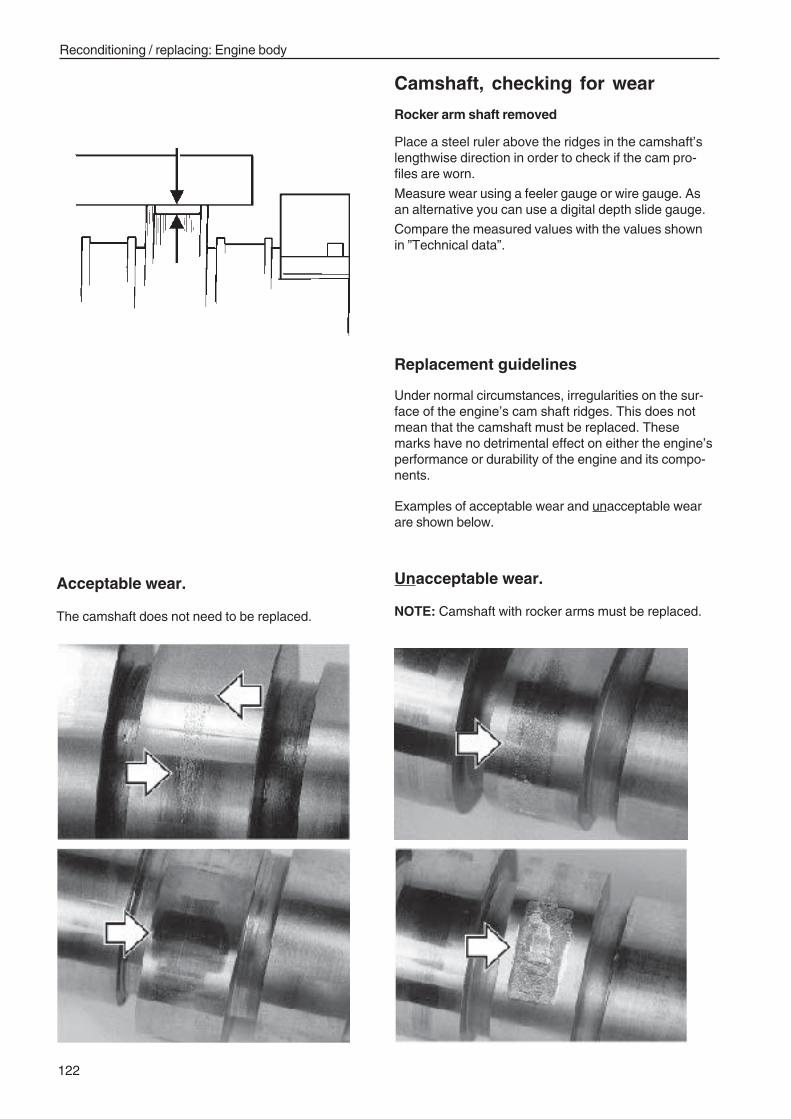
122
Reconditioning / replacing: Engine body
Camshaft, checking for wear
Rocker arm shaft removed
Place a steel ruler above the ridges in the camshaft’slengthwise direction in order to check if the cam pro-files are worn.
Measure wear using a feeler gauge or wire gauge. Asan alternative you can use a digital depth slide gauge.
Compare the measured values with the values shownin ”Technical data”.
Replacement guidelines
Under normal circumstances, irregularities on the sur-face of the engine’s cam shaft ridges. This does notmean that the camshaft must be replaced. Thesemarks have no detrimental effect on either the engine’sperformance or durability of the engine and its compo-nents.
Examples of acceptable wear and unacceptable wearare shown below.
Acceptable wear.
The camshaft does not need to be replaced.
Unacceptable wear.
NOTE: Camshaft with rocker arms must be replaced.
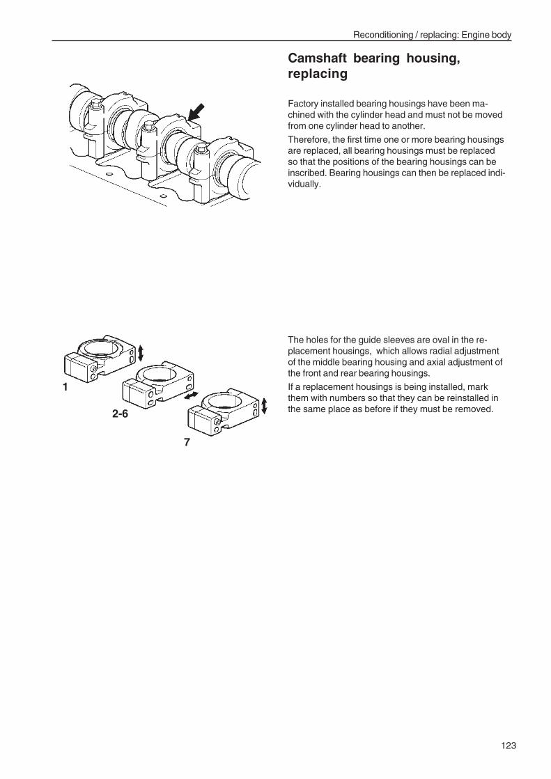
123
Reconditioning / replacing: Engine body
Camshaft bearing housing,replacing
Factory installed bearing housings have been ma-chined with the cylinder head and must not be movedfrom one cylinder head to another.
Therefore, the first time one or more bearing housingsare replaced, all bearing housings must be replacedso that the positions of the bearing housings can beinscribed. Bearing housings can then be replaced indi-vidually.
The holes for the guide sleeves are oval in the re-placement housings, which allows radial adjustmentof the middle bearing housing and axial adjustment ofthe front and rear bearing housings.
If a replacement housings is being installed, markthem with numbers so that they can be reinstalled inthe same place as before if they must be removed.
1
7
2-6
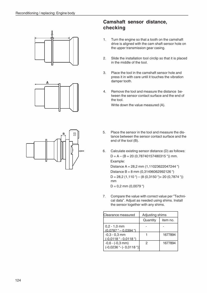
124
Reconditioning / replacing: Engine body
5. Place the sensor in the tool and measure the dis-tance between the sensor contact surface and theend of the tool (B).
6. Calculate existing sensor distance (D) as follows:
D = A – (B + 20 (0,78740157480315 “)) mm.
Example:
Distance A = 28,2 mm (1,11023622047244 “)
Distance B = 8 mm (0,31496062992126 “)
D = 28,2 (1,110 “) – (8 (0,3150 “)+ 20 (0,7874 “))mm
D = 0,2 mm (0,0079 “)
7. Compare the value with correct value per ”Techni-cal data”. Adjust as needed using shims. Installthe sensor together with any shims.
Clearance measured Adjusting shims
Quantity item no.
Camshaft sensor distance,checking
1. Turn the engine so that a tooth on the camshaftdrive is aligned with the cam shaft sensor hole onthe upper transmission gear casing.
2. Slide the installation tool circlip so that it is placedin the middle of the tool.
3. Place the tool in the camshaft sensor hole andpress it in with care until it touches the vibrationdamper tooth.
4. Remove the tool and measure the distance be-tween the sensor contact surface and the end ofthe tool.
Write down the value measured (A).
0,2 - 1,0 mm - -(0,0787 “ – 0,0394 “)-0,3 - 0,3 mm 1 1677894(-0,0118 “ - 0,0118 “)-0,6 - (-0,3 mm) 2 1677894(-0,0236 “- (- 0,0118 “))
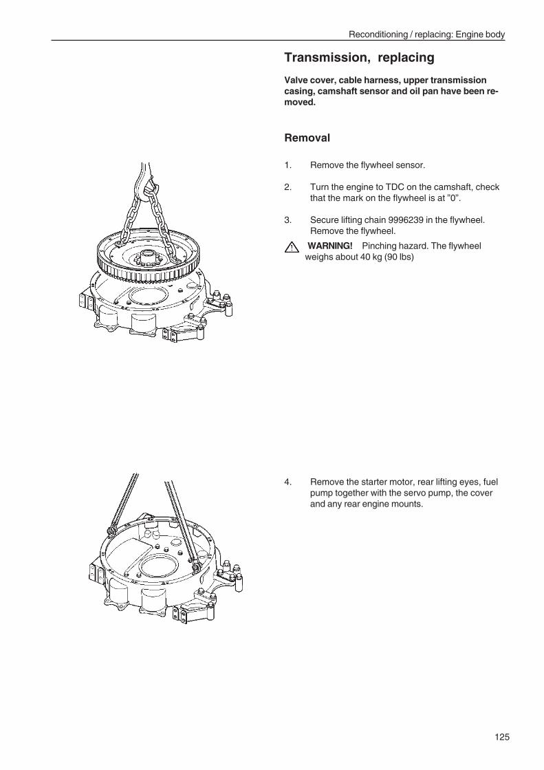
125
Reconditioning / replacing: Engine body
Transmission, replacing
Valve cover, cable harness, upper transmissioncasing, camshaft sensor and oil pan have been re-moved.
Removal
1. Remove the flywheel sensor.
2. Turn the engine to TDC on the camshaft, checkthat the mark on the flywheel is at ”0”.
3. Secure lifting chain 9996239 in the flywheel.Remove the flywheel.
WARNING! Pinching hazard. The flywheelweighs about 40 kg (90 lbs)
4. Remove the starter motor, rear lifting eyes, fuelpump together with the servo pump, the coverand any rear engine mounts.
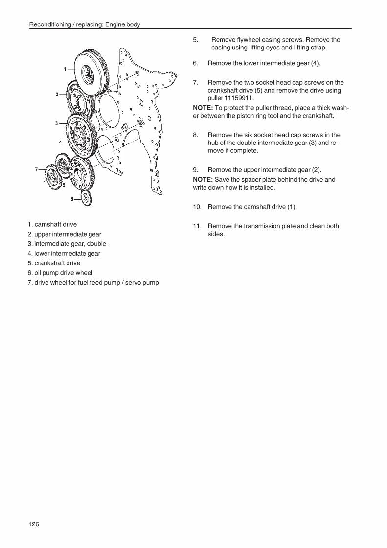
126
Reconditioning / replacing: Engine body
1. camshaft drive
2. upper intermediate gear
3. intermediate gear, double
4. lower intermediate gear
5. crankshaft drive
6. oil pump drive wheel
7. drive wheel for fuel feed pump / servo pump
5. Remove flywheel casing screws. Remove thecasing using lifting eyes and lifting strap.
6. Remove the lower intermediate gear (4).
7. Remove the two socket head cap screws on thecrankshaft drive (5) and remove the drive usingpuller 11159911.
NOTE: To protect the puller thread, place a thick wash-er between the piston ring tool and the crankshaft.
8. Remove the six socket head cap screws in thehub of the double intermediate gear (3) and re-move it complete.
9. Remove the upper intermediate gear (2).
NOTE: Save the spacer plate behind the drive andwrite down how it is installed.
10. Remove the camshaft drive (1).
11. Remove the transmission plate and clean bothsides.
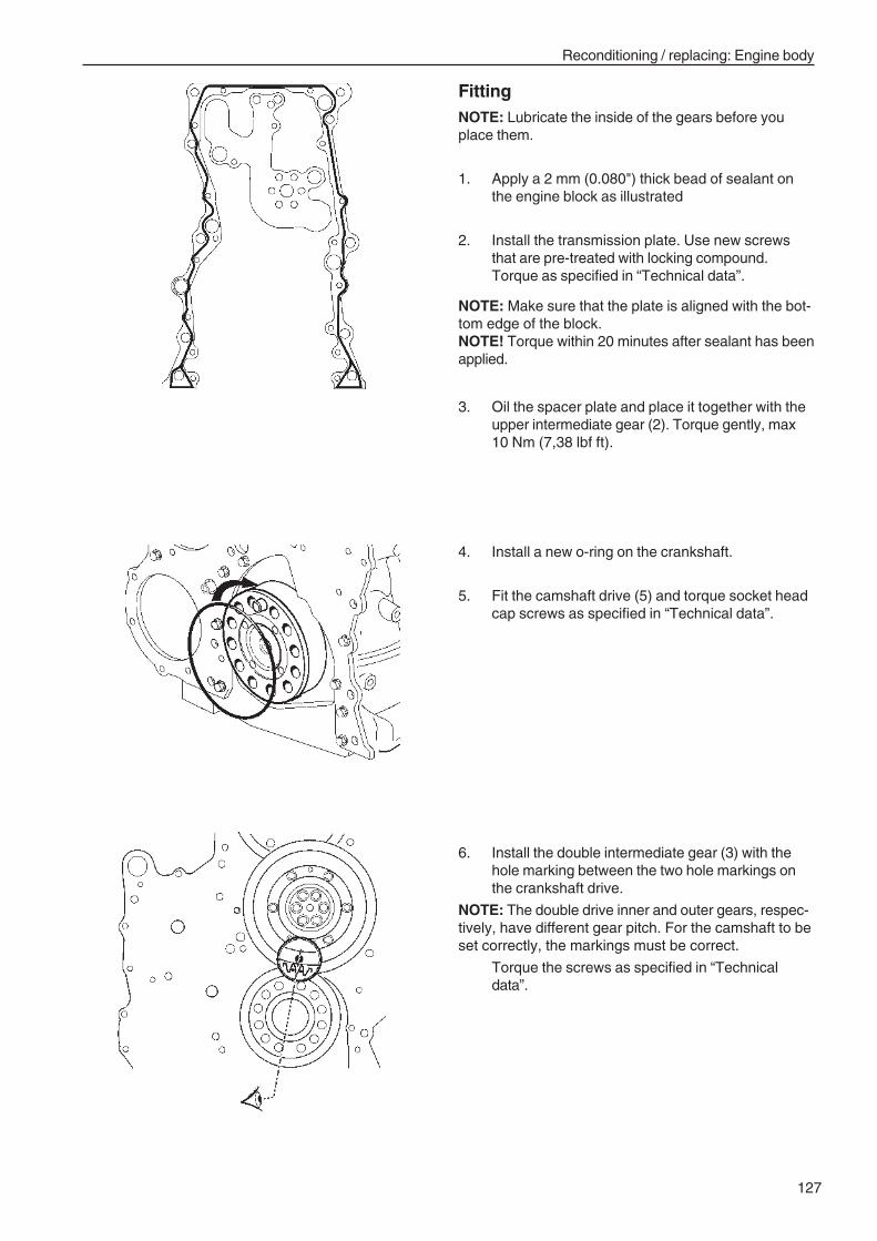
127
Reconditioning / replacing: Engine body
FittingNOTE: Lubricate the inside of the gears before youplace them.
1. Apply a 2 mm (0.080") thick bead of sealant onthe engine block as illustrated
2. Install the transmission plate. Use new screwsthat are pre-treated with locking compound.Torque as specified in “Technical data”.
NOTE: Make sure that the plate is aligned with the bot-tom edge of the block.NOTE! Torque within 20 minutes after sealant has beenapplied.
3. Oil the spacer plate and place it together with theupper intermediate gear (2). Torque gently, max10 Nm (7,38 lbf ft).
4. Install a new o-ring on the crankshaft.
5. Fit the camshaft drive (5) and torque socket headcap screws as specified in “Technical data”.
6. Install the double intermediate gear (3) with thehole marking between the two hole markings onthe crankshaft drive.
NOTE: The double drive inner and outer gears, respec-tively, have different gear pitch. For the camshaft to beset correctly, the markings must be correct.
Torque the screws as specified in “Technicaldata”.
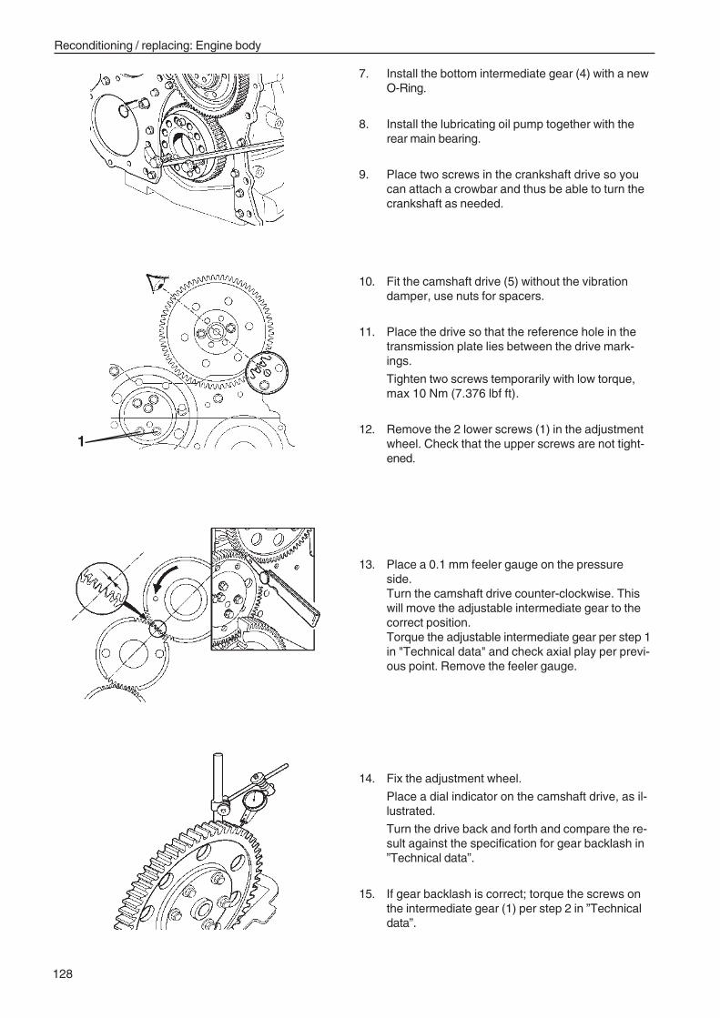
128
Reconditioning / replacing: Engine body
7. Install the bottom intermediate gear (4) with a newO-Ring.
8. Install the lubricating oil pump together with therear main bearing.
9. Place two screws in the crankshaft drive so youcan attach a crowbar and thus be able to turn thecrankshaft as needed.
10. Fit the camshaft drive (5) without the vibrationdamper, use nuts for spacers.
11. Place the drive so that the reference hole in thetransmission plate lies between the drive mark-ings.
Tighten two screws temporarily with low torque,max 10 Nm (7.376 lbf ft).
12. Remove the 2 lower screws (1) in the adjustmentwheel. Check that the upper screws are not tight-ened.
13. Place a 0.1 mm feeler gauge on the pressureside.Turn the camshaft drive counter-clockwise. Thiswill move the adjustable intermediate gear to thecorrect position.Torque the adjustable intermediate gear per step 1in "Technical data" and check axial play per previ-ous point. Remove the feeler gauge.
14. Fix the adjustment wheel.
Place a dial indicator on the camshaft drive, as il-lustrated.
Turn the drive back and forth and compare the re-sult against the specification for gear backlash in”Technical data”.
15. If gear backlash is correct; torque the screws onthe intermediate gear (1) per step 2 in ”Technicaldata”.
1
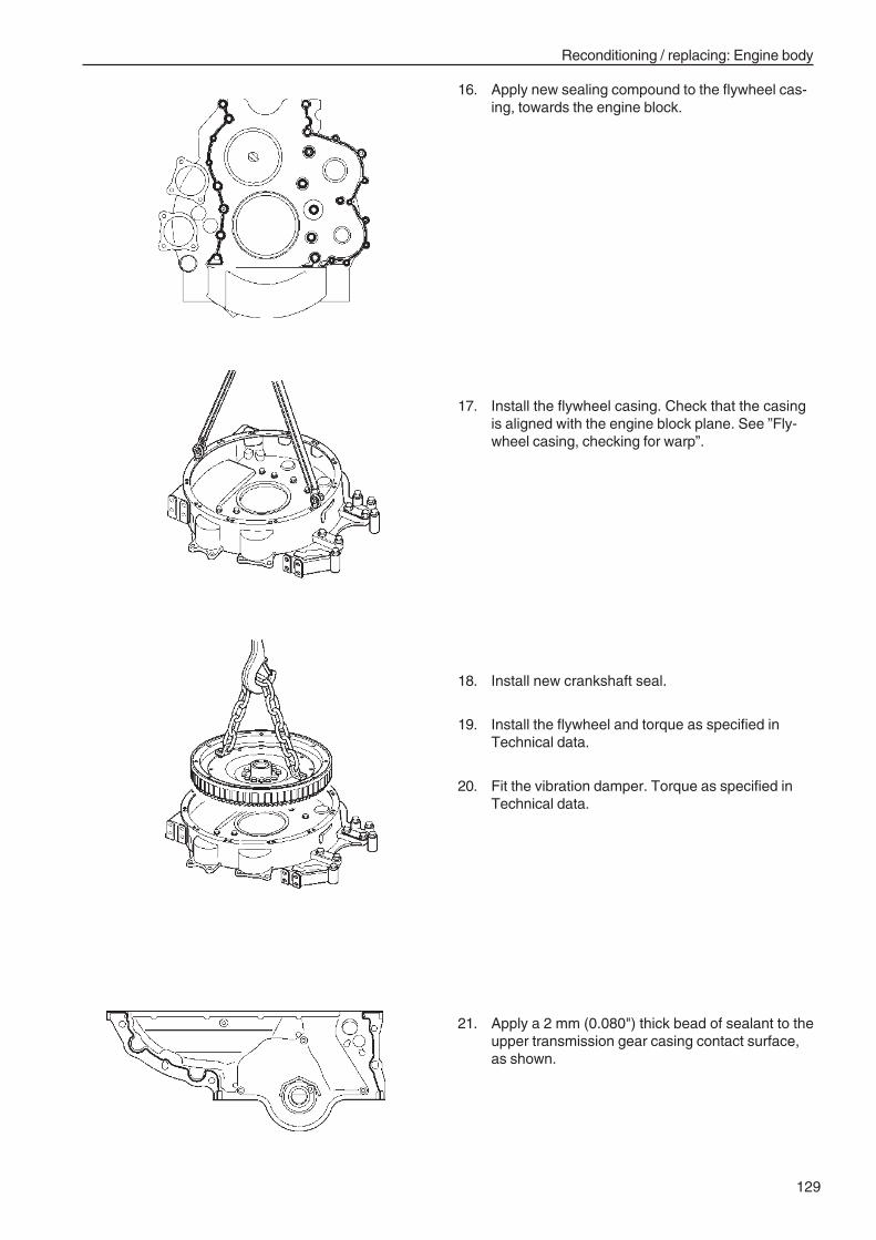
129
Reconditioning / replacing: Engine body
16. Apply new sealing compound to the flywheel cas-ing, towards the engine block.
17. Install the flywheel casing. Check that the casingis aligned with the engine block plane. See ”Fly-wheel casing, checking for warp”.
18. Install new crankshaft seal.
19. Install the flywheel and torque as specified inTechnical data.
20. Fit the vibration damper. Torque as specified inTechnical data.
21. Apply a 2 mm (0.080") thick bead of sealant to theupper transmission gear casing contact surface,as shown.
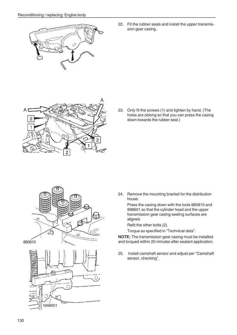
130
Reconditioning / replacing: Engine body
22. Fit the rubber seals and install the upper transmis-sion gear casing.
24. Remove the mounting bracket for the distributionhouse.
Press the casing down with the tools 885810 and998601 so that the cylinder head and the uppertransmission gear casing sealing surfaces arealigned.
Refit the other bolts (2).
Torque as specified in “Technical data”.
NOTE: The transmission gear casing must be installedand torqued within 20 minutes after sealant application.
25. Install camshaft sensor and adjust per ”Camshaftsensor, checking”.
23. Only fit the screws (1) and tighten by hand. (Theholes are oblong so that you can press the casingdown towards the rubber seal.)
885810
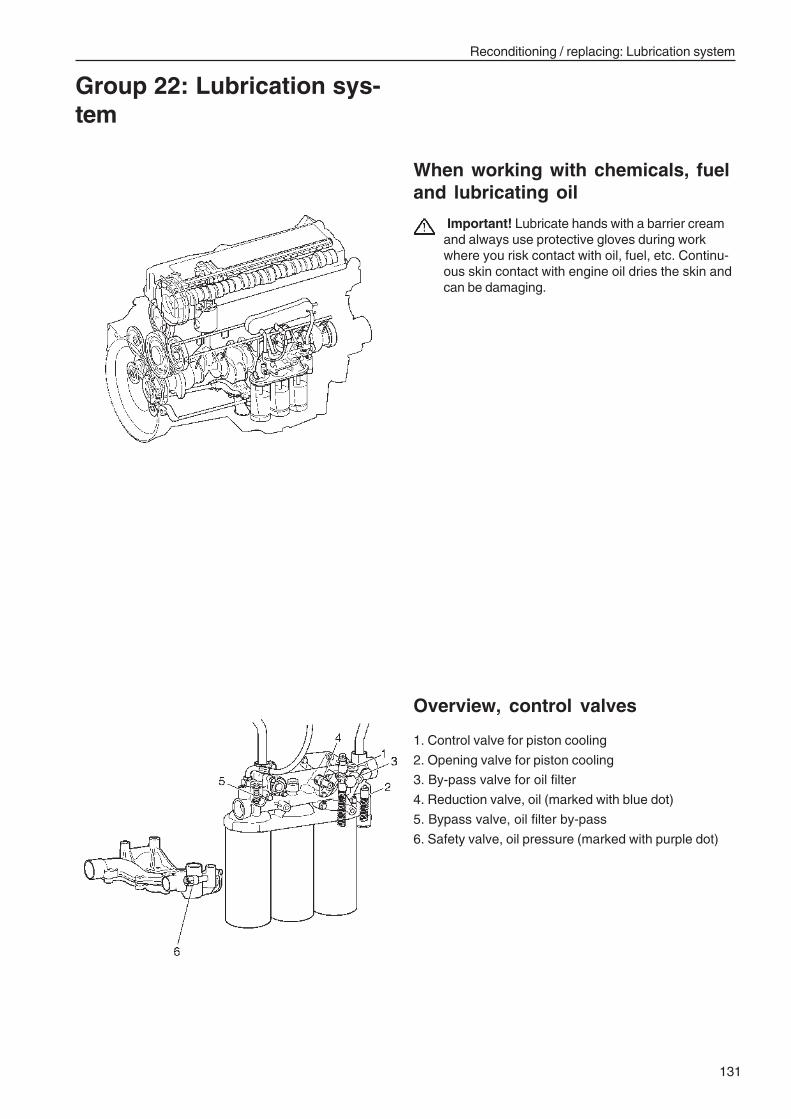
Reconditioning / replacing: Lubrication system
131
When working with chemicals, fueland lubricating oil
Important! Lubricate hands with a barrier creamand always use protective gloves during workwhere you risk contact with oil, fuel, etc. Continu-ous skin contact with engine oil dries the skin andcan be damaging.
Group 22: Lubrication sys-tem
1. Control valve for piston cooling
2. Opening valve for piston cooling
3. By-pass valve for oil filter
4. Reduction valve, oil (marked with blue dot)
5. Bypass valve, oil filter by-pass
6. Safety valve, oil pressure (marked with purple dot)
Overview, control valves
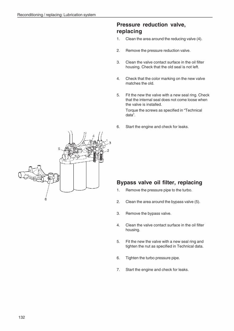
Reconditioning / replacing: Lubrication system
132
Bypass valve oil filter, replacing1. Remove the pressure pipe to the turbo.
2. Clean the area around the bypass valve (5).
3. Remove the bypass valve.
4. Clean the valve contact surface in the oil filterhousing.
5. Fit the new the valve with a new seal ring andtighten the nut as specified in Technical data.
6. Tighten the turbo pressure pipe.
7. Start the engine and check for leaks.
Pressure reduction valve,replacing1. Clean the area around the reducing valve (4).
2. Remove the pressure reduction valve.
3. Clean the valve contact surface in the oil filterhousing. Check that the old seal is not left.
4. Check that the color marking on the new valvematches the old.
5. Fit the new the valve with a new seal ring. Checkthat the internal seal does not come loose whenthe valve is installed.
Torque the screws as specified in “Technicaldata”.
6. Start the engine and check for leaks.
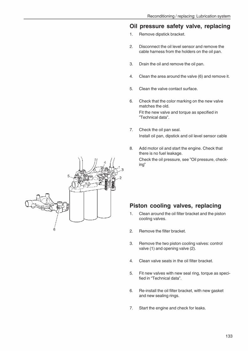
Reconditioning / replacing: Lubrication system
133
Piston cooling valves, replacing1. Clean around the oil filter bracket and the piston
cooling valves.
2. Remove the filter bracket.
3. Remove the two piston cooling valves: controlvalve (1) and opening valve (2).
4. Clean valve seats in the oil filter bracket.
5. Fit new valves with new seal ring, torque as speci-fied in “Technical data”.
6. Re-install the oil filter bracket, with new gasketand new sealing rings.
7. Start the engine and check for leaks.
Oil pressure safety valve, replacing1. Remove dipstick bracket.
2. Disconnect the oil level sensor and remove thecable harness from the holders on the oil pan.
3. Drain the oil and remove the oil pan.
4. Clean the area around the valve (6) and remove it.
5. Clean the valve contact surface.
6. Check that the color marking on the new valvematches the old.
Fit the new valve and torque as specified in”Technical data”.
7. Check the oil pan seal.
Install oil pan, dipstick and oil level sensor cable
8. Add motor oil and start the engine. Check thatthere is no fuel leakage.
Check the oil pressure, see ”Oil pressure, check-ing”
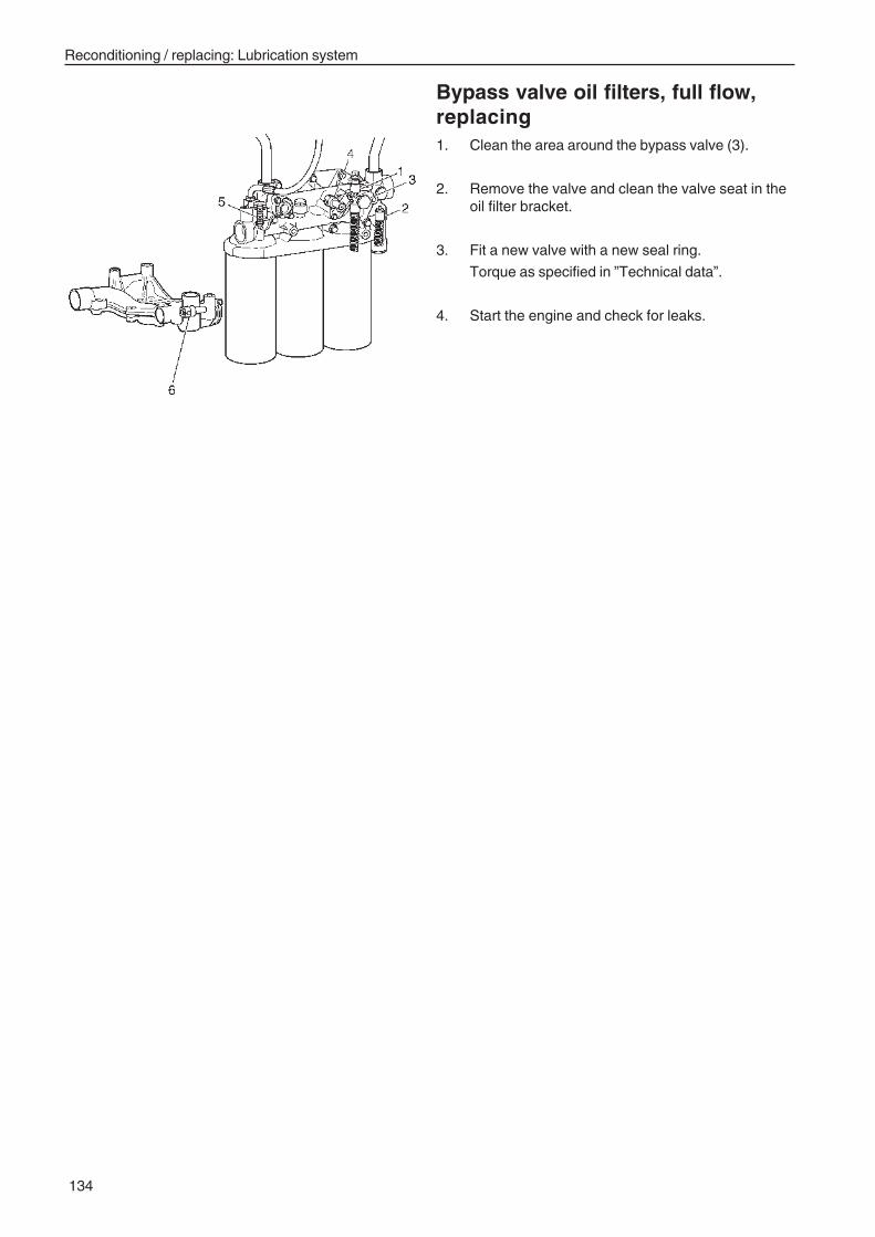
Reconditioning / replacing: Lubrication system
134
Bypass valve oil filters, full flow,replacing1. Clean the area around the bypass valve (3).
2. Remove the valve and clean the valve seat in theoil filter bracket.
3. Fit a new valve with a new seal ring.
Torque as specified in ”Technical data”.
4. Start the engine and check for leaks.
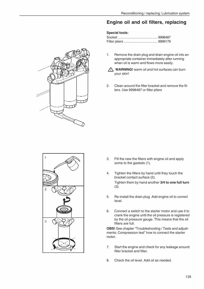
Reconditioning / replacing: Lubrication system
135
Engine oil and oil filters, replacing
Special tools:Socket ......................................... 9998487Filter pliers ................................... 9999179
1. Remove the drain plug and drain engine oil into anappropriate container immediately after runningwhen oil is warm and flows more easily.
WARNING! warm oil and hot surfaces can burnyour skin!
2. Clean around the filter bracket and remove the fil-ters. Use 9998487 or filter pliers
3. Fill the new the filters with engine oil and applysome to the gaskets (1).
4. Tighten the filters by hand until they touch thebracket contact surface (2).
Tighten them by hand another 3/4 to one full turn(3).
5. Re-install the drain plug. Add engine oil to correctlevel.
6. Connect a switch to the starter motor and use it tocrank the engine until the oil pressure is registeredby the oil pressure gauge. This means that the oilfilters are full.
OBS! See chapter “Troubleshooting / Tests and adjust-ments; Compression test” how to connect the startermotor.
7. Start the engine and check for any leakage aroundfilter bracket and filter.
8. Check the oil level. Add oil as needed.
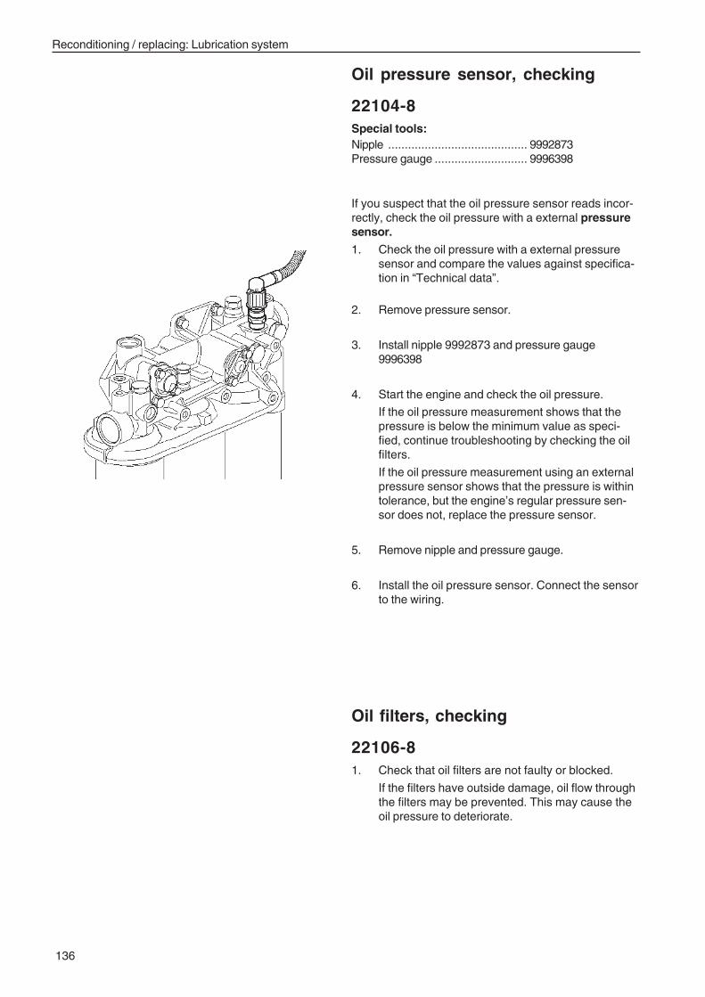
Reconditioning / replacing: Lubrication system
136
Oil pressure sensor, checking
22104-8Special tools:Nipple .......................................... 9992873Pressure gauge ............................ 9996398
If you suspect that the oil pressure sensor reads incor-rectly, check the oil pressure with a external pressuresensor.
1. Check the oil pressure with a external pressuresensor and compare the values against specifica-tion in “Technical data”.
2. Remove pressure sensor.
3. Install nipple 9992873 and pressure gauge9996398
4. Start the engine and check the oil pressure.
If the oil pressure measurement shows that thepressure is below the minimum value as speci-fied, continue troubleshooting by checking the oilfilters.
If the oil pressure measurement using an externalpressure sensor shows that the pressure is withintolerance, but the engine’s regular pressure sen-sor does not, replace the pressure sensor.
5. Remove nipple and pressure gauge.
6. Install the oil pressure sensor. Connect the sensorto the wiring.
Oil filters, checking
22106-81. Check that oil filters are not faulty or blocked.
If the filters have outside damage, oil flow throughthe filters may be prevented. This may cause theoil pressure to deteriorate.
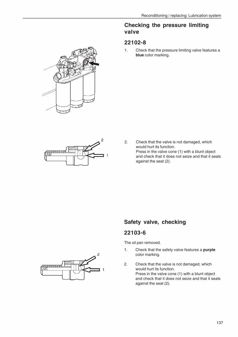
Reconditioning / replacing: Lubrication system
137
Checking the pressure limitingvalve
22102-81. Check that the pressure limiting valve features a
blue color marking.
2. Check that the valve is not damaged, whichwould hurt its function.Press in the valve cone (1) with a blunt objectand check that it does not seize and that it sealsagainst the seat (2).
Safety valve, checking
22103-6
The oil pan removed.
1. Check that the safety valve features a purplecolor marking.
2. Check that the valve is not damaged, whichwould hurt its function.Press in the valve cone (1) with a blunt objectand check that it does not seize and that it sealsagainst the seat (2).
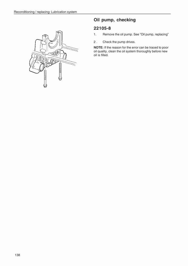
Reconditioning / replacing: Lubrication system
138
Oil pump, checking
22105-81. Remove the oil pump. See ”Oil pump, replacing”
2 . Check the pump drives.
NOTE: If the reason for the error can be traced to pooroil quality, clean the oil system thoroughly before newoil is filled.
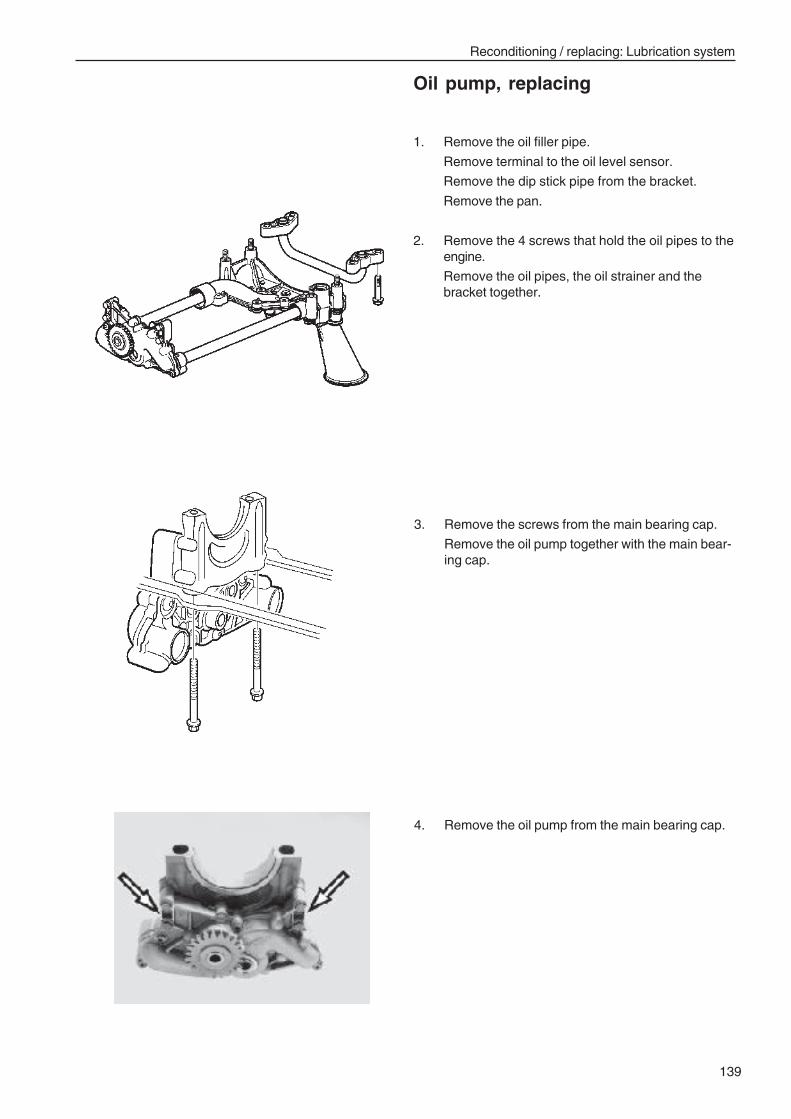
Reconditioning / replacing: Lubrication system
139
Oil pump, replacing
1. Remove the oil filler pipe.
Remove terminal to the oil level sensor.
Remove the dip stick pipe from the bracket.
Remove the pan.
2. Remove the 4 screws that hold the oil pipes to theengine.
Remove the oil pipes, the oil strainer and thebracket together.
3. Remove the screws from the main bearing cap.
Remove the oil pump together with the main bear-ing cap.
4. Remove the oil pump from the main bearing cap.
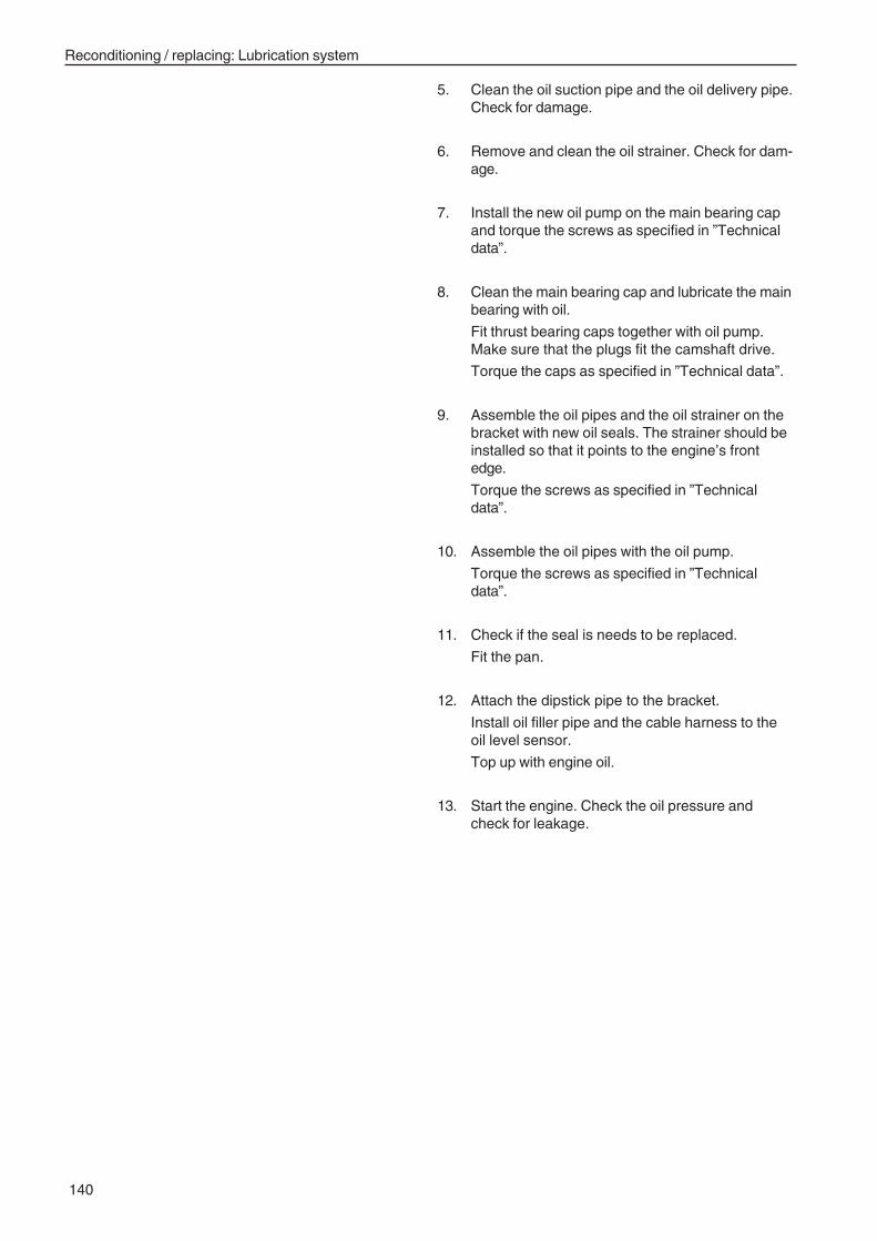
Reconditioning / replacing: Lubrication system
140
5. Clean the oil suction pipe and the oil delivery pipe.Check for damage.
6. Remove and clean the oil strainer. Check for dam-age.
7. Install the new oil pump on the main bearing capand torque the screws as specified in ”Technicaldata”.
8. Clean the main bearing cap and lubricate the mainbearing with oil.
Fit thrust bearing caps together with oil pump.Make sure that the plugs fit the camshaft drive.
Torque the caps as specified in ”Technical data”.
9. Assemble the oil pipes and the oil strainer on thebracket with new oil seals. The strainer should beinstalled so that it points to the engine’s frontedge.
Torque the screws as specified in ”Technicaldata”.
10. Assemble the oil pipes with the oil pump.
Torque the screws as specified in ”Technicaldata”.
11. Check if the seal is needs to be replaced.
Fit the pan.
12. Attach the dipstick pipe to the bracket.
Install oil filler pipe and the cable harness to theoil level sensor.
Top up with engine oil.
13. Start the engine. Check the oil pressure andcheck for leakage.
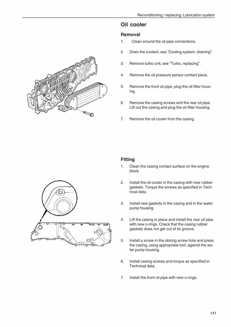
Reconditioning / replacing: Lubrication system
141
Oil cooler
Removal1. Clean around the oil pipe connections.
2. Drain the coolant, see ”Cooling system, draining”.
3. Remove turbo unit, see ”Turbo, replacing”.
4. Remove the oil pressure sensor contact piece.
5. Remove the front oil pipe, plug the oil filter hous-ing.
6. Remove the casing screws and the rear oil pipe.Lift out the casing and plug the oil filter housing.
7. Remove the oil cooler from the casing.
Fitting1. Clean the casing contact surface on the engine
block.
2. Install the oil cooler in the casing with new rubbergaskets. Torque the screws as specified in Tech-nical data.
3. Install new gaskets in the casing and in the waterpump housing.
4. Lift the casing in place and install the rear oil pipewith new o-rings. Check that the casing rubbergaskets does not get out of its groove.
5. Install a screw in the oblong screw hole and pressthe casing, using appropriate tool, against the wa-ter pump housing.
6. Install casing screws and torque as specified inTechnical data.
7. Install the front oil pipe with new o-rings.
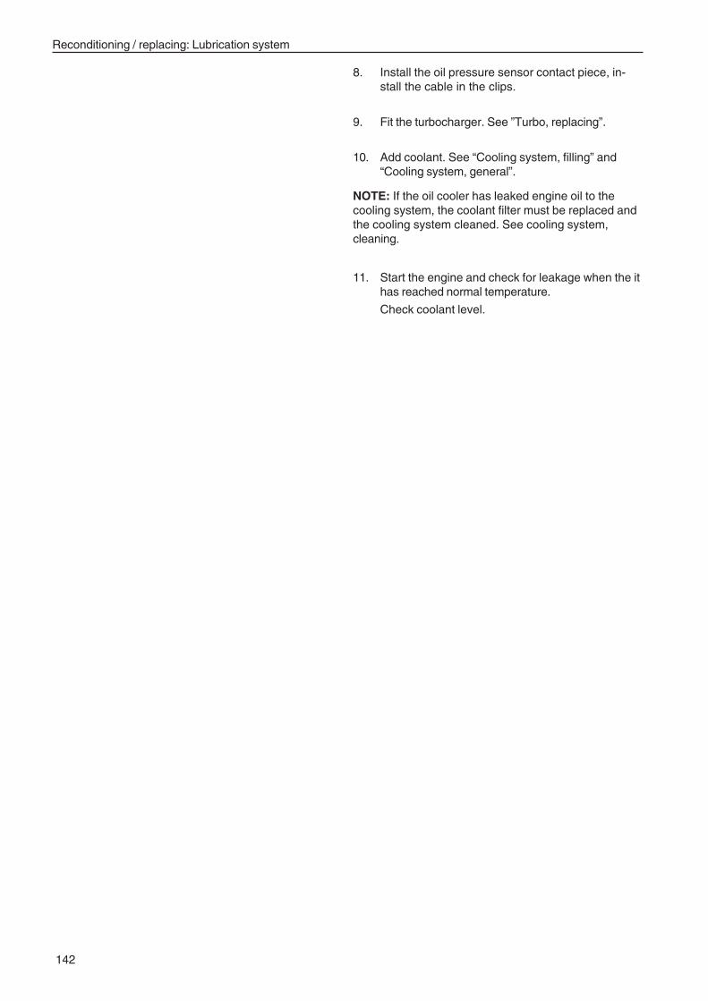
Reconditioning / replacing: Lubrication system
142
8. Install the oil pressure sensor contact piece, in-stall the cable in the clips.
9. Fit the turbocharger. See ”Turbo, replacing”.
10. Add coolant. See “Cooling system, filling” and“Cooling system, general”.
NOTE: If the oil cooler has leaked engine oil to thecooling system, the coolant filter must be replaced andthe cooling system cleaned. See cooling system,cleaning.
11. Start the engine and check for leakage when the ithas reached normal temperature.
Check coolant level.
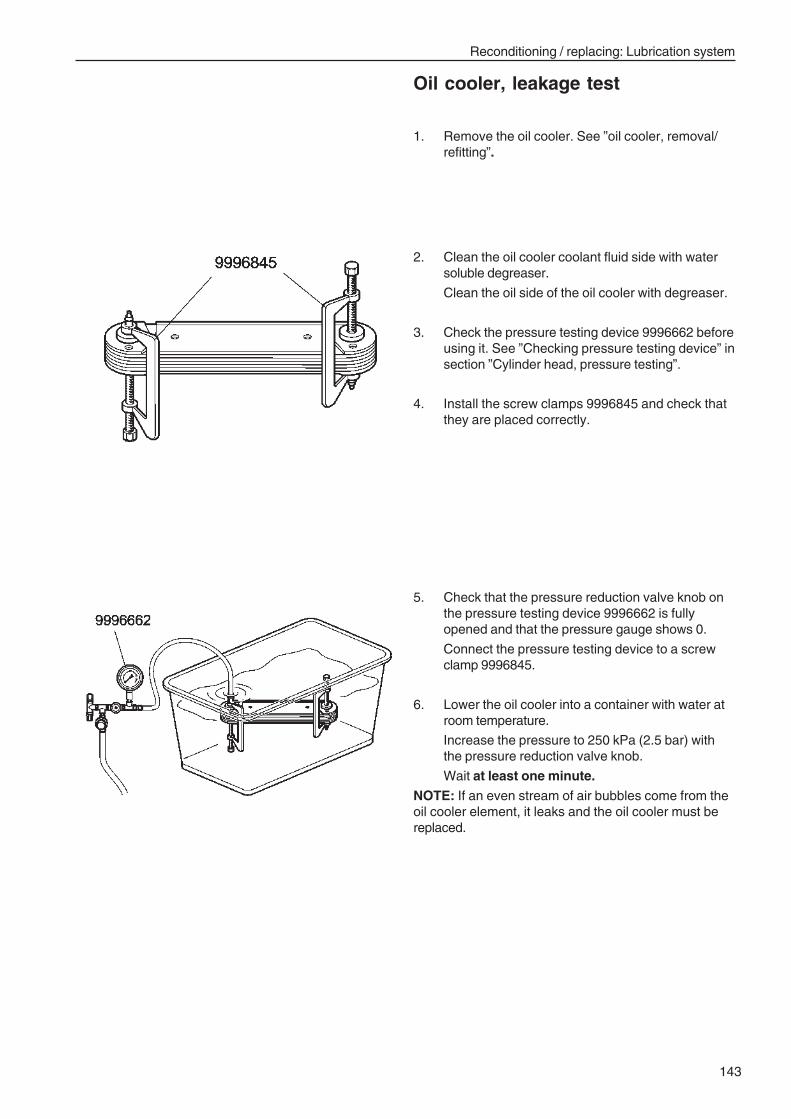
Reconditioning / replacing: Lubrication system
143
Oil cooler, leakage test
1. Remove the oil cooler. See ”oil cooler, removal/refitting”.
2. Clean the oil cooler coolant fluid side with watersoluble degreaser.
Clean the oil side of the oil cooler with degreaser.
3. Check the pressure testing device 9996662 beforeusing it. See ”Checking pressure testing device” insection ”Cylinder head, pressure testing”.
4. Install the screw clamps 9996845 and check thatthey are placed correctly.
5. Check that the pressure reduction valve knob onthe pressure testing device 9996662 is fullyopened and that the pressure gauge shows 0.
Connect the pressure testing device to a screwclamp 9996845.
6. Lower the oil cooler into a container with water atroom temperature.
Increase the pressure to 250 kPa (2.5 bar) withthe pressure reduction valve knob.
Wait at least one minute.
NOTE: If an even stream of air bubbles come from theoil cooler element, it leaks and the oil cooler must bereplaced.
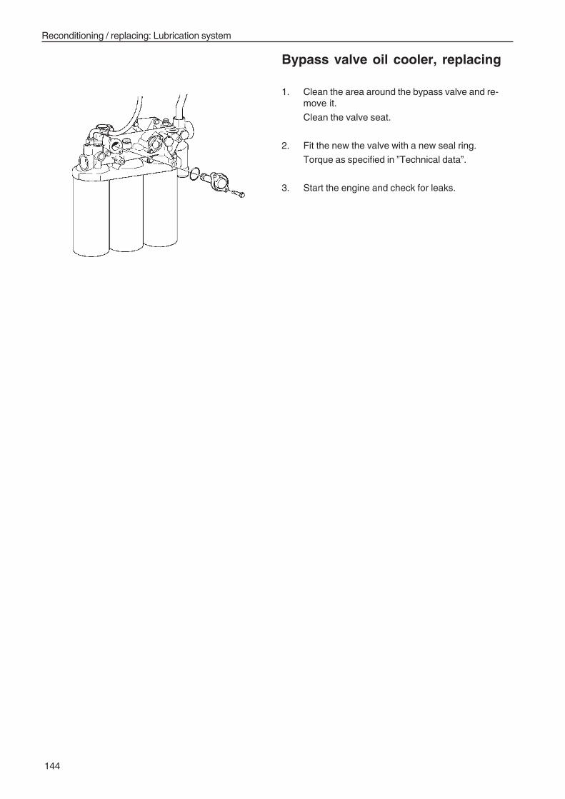
Reconditioning / replacing: Lubrication system
144
Bypass valve oil cooler, replacing
1. Clean the area around the bypass valve and re-move it.
Clean the valve seat.
2. Fit the new the valve with a new seal ring.
Torque as specified in ”Technical data”.
3. Start the engine and check for leaks.
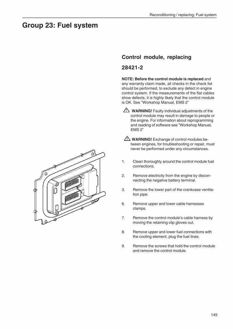
Reconditioning / replacing: Fuel system
145
Group 23: Fuel system
Control module, replacing
28421-2
NOTE: Before the control module is replaced andany warranty claim made, all checks in the check listshould be performed, to exclude any defect in enginecontrol system. If the measurements of the flat cablesshow defects, it is highly likely that the control moduleis OK. See ”Workshop Manual, EMS 2”
WARNING! Faulty individual adjustments of thecontrol module may result in damage to people orthe engine. For information about reprogrammingand reading of software see ”Workshop Manual,EMS 2”
WARNING! Exchange of control modules be-tween engines, for troubleshooting or repair, mustnever be performed under any circumstances.
1. Clean thoroughly around the control module fuelconnections.
2. Remove electricity from the engine by discon-necting the negative battery terminal.
3. Remove the lower part of the crankcase ventila-tion pipe.
6. Remove upper and lower cable harnessesclamps.
7. Remove the control module’s cable harness bymoving the retaining clip gloves out.
8. Remove upper and lower fuel connections withthe cooling element, plug the fuel lines.
9. Remove the screws that hold the control moduleand remove the control module.
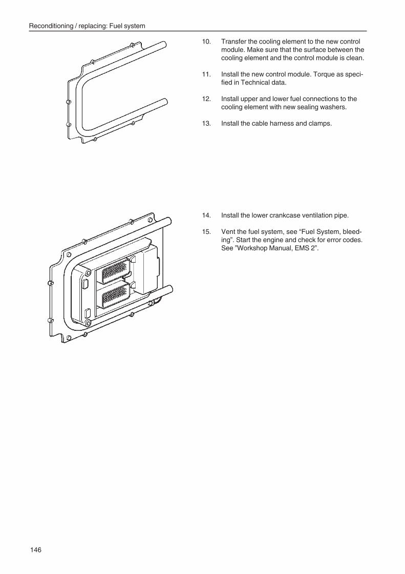
Reconditioning / replacing: Fuel system
146
10. Transfer the cooling element to the new controlmodule. Make sure that the surface between thecooling element and the control module is clean.
11. Install the new control module. Torque as speci-fied in Technical data.
12. Install upper and lower fuel connections to thecooling element with new sealing washers.
13. Install the cable harness and clamps.
14. Install the lower crankcase ventilation pipe.
15. Vent the fuel system, see “Fuel System, bleed-ing”. Start the engine and check for error codes.See ”Workshop Manual, EMS 2”.
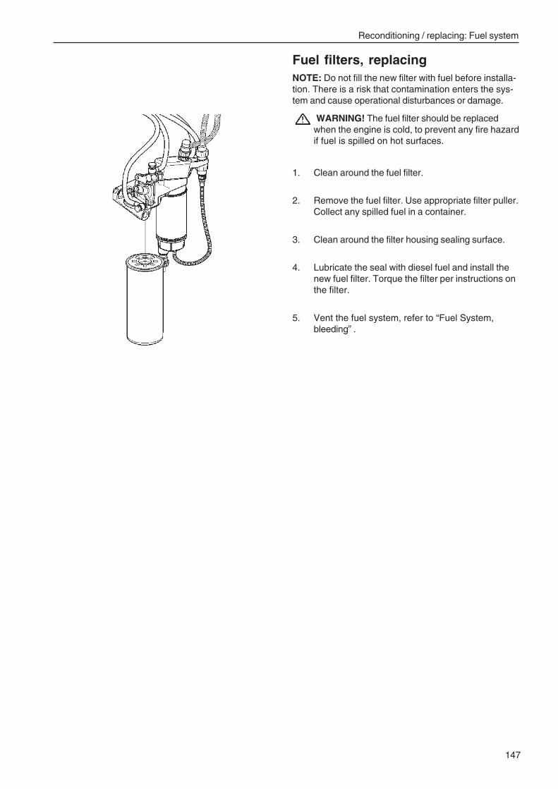
Reconditioning / replacing: Fuel system
147
Fuel filters, replacingNOTE: Do not fill the new filter with fuel before installa-tion. There is a risk that contamination enters the sys-tem and cause operational disturbances or damage.
WARNING! The fuel filter should be replacedwhen the engine is cold, to prevent any fire hazardif fuel is spilled on hot surfaces.
1. Clean around the fuel filter.
2. Remove the fuel filter. Use appropriate filter puller.Collect any spilled fuel in a container.
3. Clean around the filter housing sealing surface.
4. Lubricate the seal with diesel fuel and install thenew fuel filter. Torque the filter per instructions onthe filter.
5. Vent the fuel system, refer to “Fuel System,bleeding” .
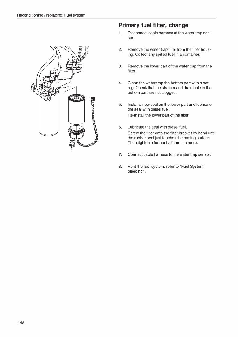
Reconditioning / replacing: Fuel system
148
Primary fuel filter, change1. Disconnect cable harness at the water trap sen-
sor.
2. Remove the water trap filter from the filter hous-ing. Collect any spilled fuel in a container.
3. Remove the lower part of the water trap from thefilter.
4. Clean the water trap the bottom part with a softrag. Check that the strainer and drain hole in thebottom part are not clogged.
5. Install a new seal on the lower part and lubricatethe seal with diesel fuel.
Re-install the lower part of the filter.
6. Lubricate the seal with diesel fuel.
Screw the filter onto the filter bracket by hand untilthe rubber seal just touches the mating surface.Then tighten a further half turn, no more.
7. Connect cable harness to the water trap sensor.
8. Vent the fuel system, refer to “Fuel System,bleeding” .
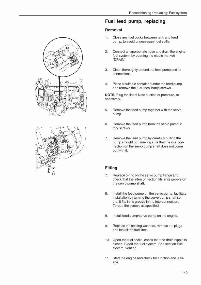
Reconditioning / replacing: Fuel system
149
Fuel feed pump, replacing
Removal
1. Close any fuel cocks between tank and feedpump, to avoid unnecessary fuel spills.
2. Connect an appropriate hose and drain the enginefuel system, by opening the nipple marked"DRAIN".
3. Clean thoroughly around the feed pump and itsconnections.
4. Place a suitable container under the feed pumpand remove the fuel lines’ banjo screws.
NOTE: Plug the lines! Note suction or pressure, re-spectively.
5. Remove the feed pump together with the servopump.
6. Remove the feed pump from the servo pump, 3torx screws.
7. Remove the feed pump by carefully pulling thepump straight out, making sure that the intercon-nection on the servo pump shaft does not comeout with it.
Fitting
7. Replace o-ring on the servo pump flange andcheck that the interconnection fits in its groove onthe servo pump shaft.
8. Install the feed pump on the servo pump, facilitateinstallation by turning the servo pump shaft sothat it fits in its groove in the interconnection.Torque the screws as specified.
9. Install feed pump/servo pump on the engine.
9. Replace the sealing washers, remove the plugsand install the fuel lines.
10. Open the fuel cocks, check that the drain nipple isclosed. Bleed the fuel system. See section Fuelsystem, venting.
11. Start the engine and check for function and leak-age.
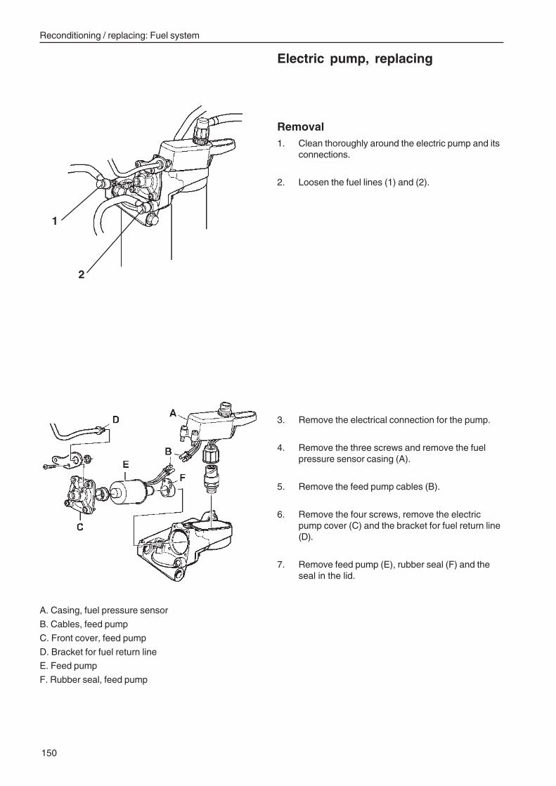
Reconditioning / replacing: Fuel system
150
Electric pump, replacing
A. Casing, fuel pressure sensor
B. Cables, feed pump
C. Front cover, feed pump
D. Bracket for fuel return line
E. Feed pump
F. Rubber seal, feed pump
Removal1. Clean thoroughly around the electric pump and its
connections.
2. Loosen the fuel lines (1) and (2).
3. Remove the electrical connection for the pump.
4. Remove the three screws and remove the fuelpressure sensor casing (A).
5. Remove the feed pump cables (B).
6. Remove the four screws, remove the electricpump cover (C) and the bracket for fuel return line(D).
7. Remove feed pump (E), rubber seal (F) and theseal in the lid.
1
2
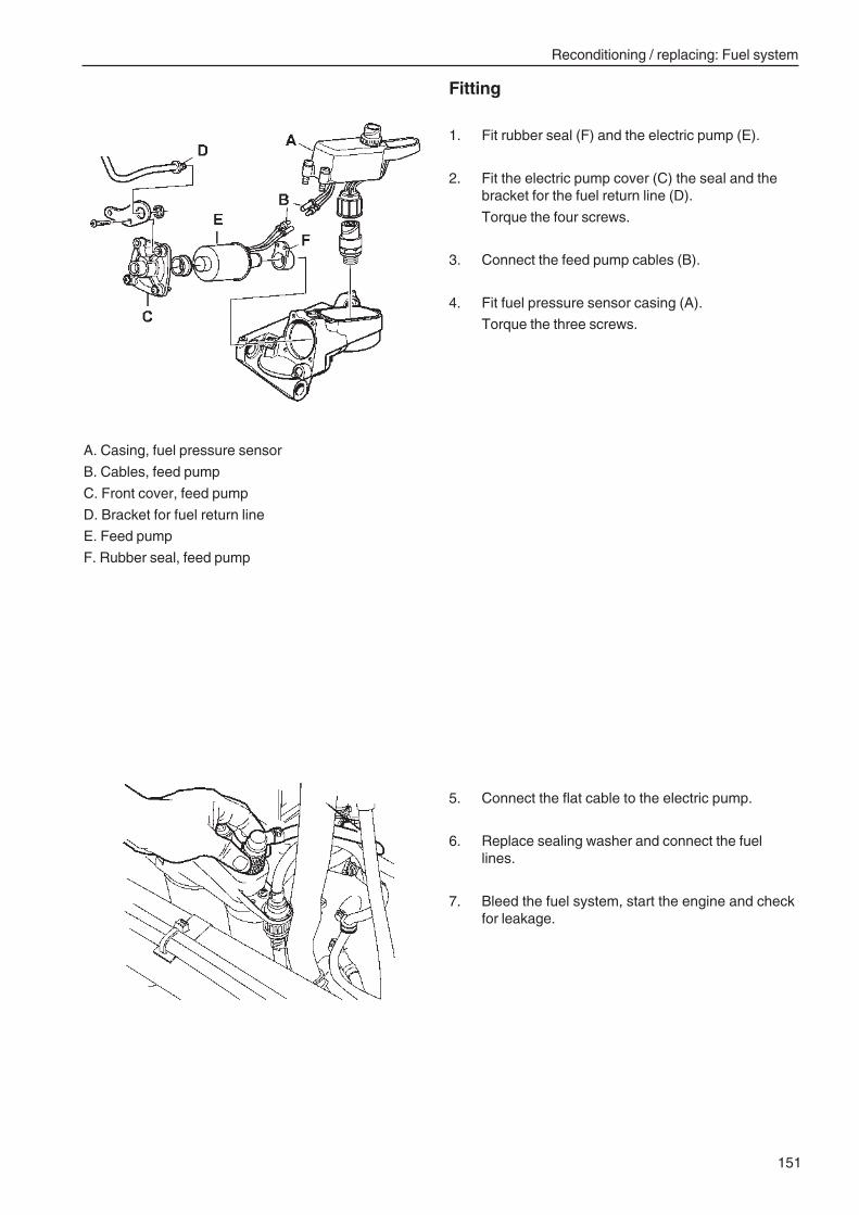
Reconditioning / replacing: Fuel system
151
Fitting
1. Fit rubber seal (F) and the electric pump (E).
2. Fit the electric pump cover (C) the seal and thebracket for the fuel return line (D).
Torque the four screws.
3. Connect the feed pump cables (B).
4. Fit fuel pressure sensor casing (A).
Torque the three screws.
A. Casing, fuel pressure sensor
B. Cables, feed pump
C. Front cover, feed pump
D. Bracket for fuel return line
E. Feed pump
F. Rubber seal, feed pump
5. Connect the flat cable to the electric pump.
6. Replace sealing washer and connect the fuellines.
7. Bleed the fuel system, start the engine and checkfor leakage.
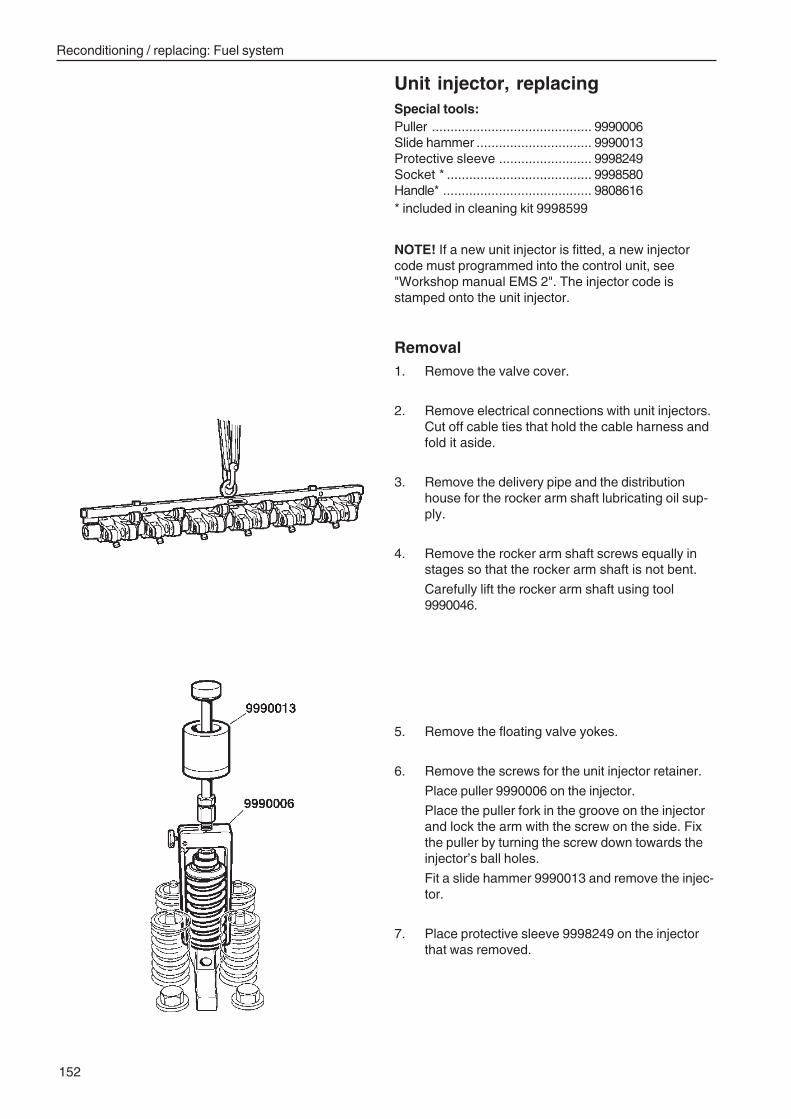
Reconditioning / replacing: Fuel system
152
Unit injector, replacingSpecial tools:Puller ........................................... 9990006Slide hammer ............................... 9990013Protective sleeve ......................... 9998249Socket * ....................................... 9998580Handle* ........................................ 9808616* included in cleaning kit 9998599
NOTE! If a new unit injector is fitted, a new injectorcode must programmed into the control unit, see"Workshop manual EMS 2". The injector code isstamped onto the unit injector.
Removal1. Remove the valve cover.
2. Remove electrical connections with unit injectors.Cut off cable ties that hold the cable harness andfold it aside.
3. Remove the delivery pipe and the distributionhouse for the rocker arm shaft lubricating oil sup-ply.
4. Remove the rocker arm shaft screws equally instages so that the rocker arm shaft is not bent.
Carefully lift the rocker arm shaft using tool9990046.
5. Remove the floating valve yokes.
6. Remove the screws for the unit injector retainer.
Place puller 9990006 on the injector.
Place the puller fork in the groove on the injectorand lock the arm with the screw on the side. Fixthe puller by turning the screw down towards theinjector’s ball holes.
Fit a slide hammer 9990013 and remove the injec-tor.
7. Place protective sleeve 9998249 on the injectorthat was removed.
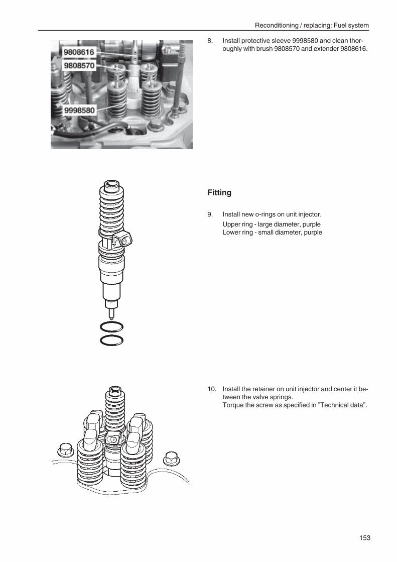
Reconditioning / replacing: Fuel system
153
8. Install protective sleeve 9998580 and clean thor-oughly with brush 9808570 and extender 9808616.
Fitting
9. Install new o-rings on unit injector.
Upper ring - large diameter, purpleLower ring - small diameter, purple
10. Install the retainer on unit injector and center it be-tween the valve springs.Torque the screw as specified in ”Technical data”.
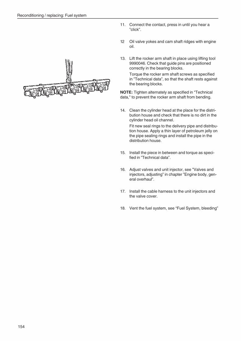
Reconditioning / replacing: Fuel system
154
11. Connect the contact, press in until you hear a”click”.
12 Oil valve yokes and cam shaft ridges with engineoil.
13. Lift the rocker arm shaft in place using lifting tool9990046. Check that guide pins are positionedcorrectly in the bearing blocks.
Torque the rocker arm shaft screws as specifiedin ”Technical data”, so that the shaft rests againstthe bearing blocks.
NOTE: Tighten alternately as specified in "Technicaldata," to prevent the rocker arm shaft from bending.
14. Clean the cylinder head at the place for the distri-bution house and check that there is no dirt in thecylinder head oil channel.
Fit new seal rings to the delivery pipe and distribu-tion house. Apply a thin layer of petroleum jelly onthe pipe sealing rings and install the pipe in thedistribution house.
15. Install the piece in between and torque as speci-fied in ”Technical data”.
16. Adjust valves and unit injector, see ”Valves andinjectors, adjusting” in chapter ”Engine body, gen-eral overhaul”.
17. Install the cable harness to the unit injectors andthe valve cover.
18. Vent the fuel system, see “Fuel System, bleeding”
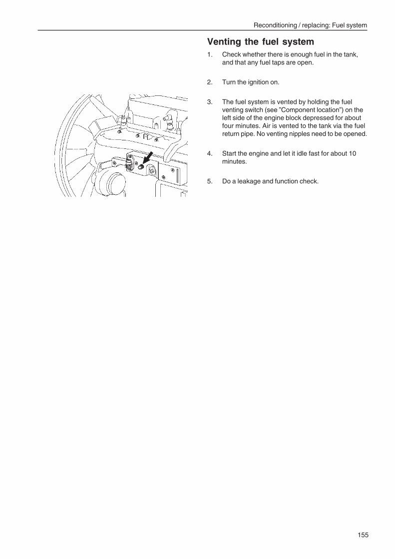
Reconditioning / replacing: Fuel system
155
Venting the fuel system1. Check whether there is enough fuel in the tank,
and that any fuel taps are open.
2. Turn the ignition on.
3. The fuel system is vented by holding the fuelventing switch (see ”Component location”) on theleft side of the engine block depressed for aboutfour minutes. Air is vented to the tank via the fuelreturn pipe. No venting nipples need to be opened.
4. Start the engine and let it idle fast for about 10minutes.
5. Do a leakage and function check.
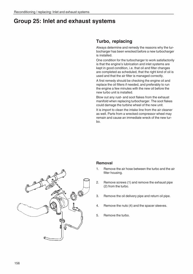
156
Reconditioning / replacing: Inlet and exhaust systems
Turbo, replacingAlways determine and remedy the reasons why the tur-bocharger has been wrecked before a new turbochargeris installed.
One condition for the turbocharger to work satisfactorilyis that the engine’s lubrication and inlet systems arekept in good condition, i.e. that oil and filter changesare completed as scheduled, that the right kind of oil isused and that the air filter is managed correctly.
A first remedy should be checking the engine oil andreplace the oil filters if needed, and preferably to runthe engine a few minutes with the new oil before thenew turbo unit is installed.
Blow out any rust- and soot flakes from the exhaustmanifold when replacing turbocharger. The soot flakescould damage the turbine wheel of the new unit.
It is import to clean the intake line from the air cleaneras well. Parts from a wrecked compressor wheel mayremain and cause an immediate wreck of the new tur-bo.
Removal1. Remove the air hose between the turbo and the air
filter housing.
2. Remove screws (1) and remove the exhaust pipe(2) from the turbo.
3. Remove the oil delivery pipe and return oil pipe.
4. Remove the nuts (4) and the spacer sleeves.
5. Remove the turbo.
Group 25: Inlet and exhaust systems
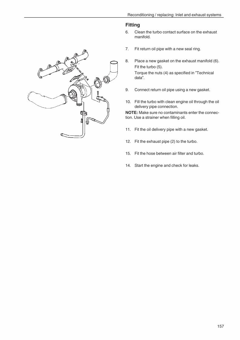
157
Reconditioning / replacing: Inlet and exhaust systems
Fitting6. Clean the turbo contact surface on the exhaust
manifold.
7. Fit return oil pipe with a new seal ring.
8. Place a new gasket on the exhaust manifold (6).
Fit the turbo (5).
Torque the nuts (4) as specified in ”Technicaldata”.
9. Connect return oil pipe using a new gasket.
10. Fill the turbo with clean engine oil through the oildelivery pipe connection.
NOTE: Make sure no contaminants enter the connec-tion. Use a strainer when filling oil.
11. Fit the oil delivery pipe with a new gasket.
12. Fit the exhaust pipe (2) to the turbo.
15. Fit the hose between air filter and turbo.
14. Start the engine and check for leaks.
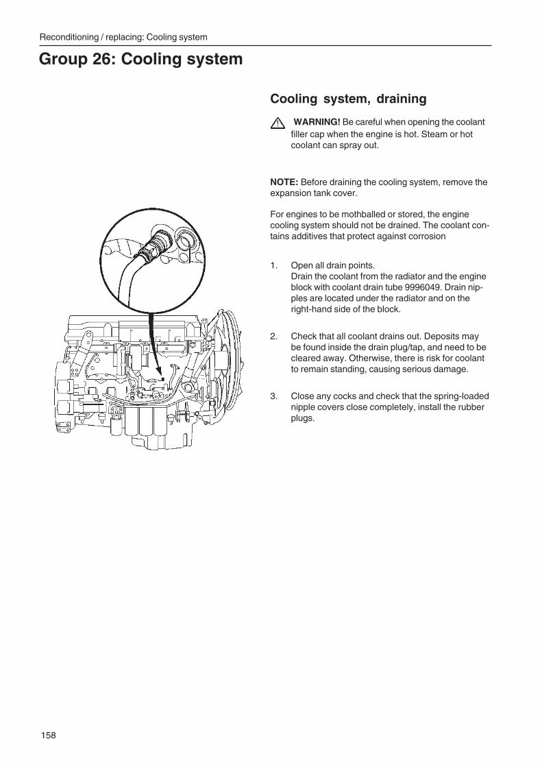
Reconditioning / replacing: Cooling system
158
Group 26: Cooling system
Cooling system, draining
WARNING! Be careful when opening the coolantfiller cap when the engine is hot. Steam or hotcoolant can spray out.
NOTE: Before draining the cooling system, remove theexpansion tank cover.
For engines to be mothballed or stored, the enginecooling system should not be drained. The coolant con-tains additives that protect against corrosion
1. Open all drain points.Drain the coolant from the radiator and the engineblock with coolant drain tube 9996049. Drain nip-ples are located under the radiator and on theright-hand side of the block.
2. Check that all coolant drains out. Deposits maybe found inside the drain plug/tap, and need to becleared away. Otherwise, there is risk for coolantto remain standing, causing serious damage.
3. Close any cocks and check that the spring-loadednipple covers close completely, install the rubberplugs.
159
Reconditioning / replacing: Inlet and exhaust systems
Cooling system, cleaning
Warning! Chemicals for the cooling system are ahealth hazard (do not ingest).
1. Empty the cooling system, see ”Cooling system,draining”, and flush with clean water.
3. Close all open cocks and fill the cooling systemwith a mix of radiator cleaner and pure water.See instruction enclosed with cleaning kit.
4. Drain the cooling system again per the aboveand flush the system with a mix of neutralizerand pure water. See instruction enclosed withcleaning kit.
5. Add new coolant when the cooling system iscompletely free from contamination. See ”Cool-ing system, general” and ”Cooling system, fill-ing”.
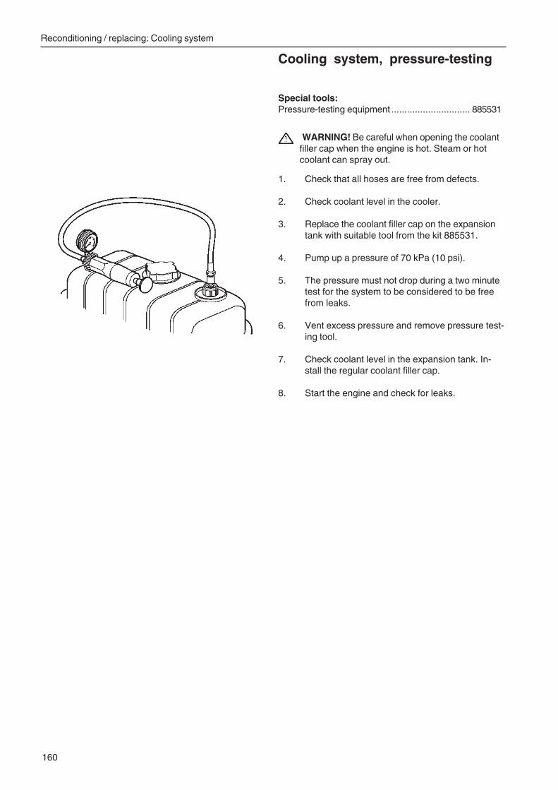
Reconditioning / replacing: Cooling system
160
Cooling system, pressure-testing
Special tools:Pressure-testing equipment .............................. 885531
WARNING! Be careful when opening the coolantfiller cap when the engine is hot. Steam or hotcoolant can spray out.
1. Check that all hoses are free from defects.
2. Check coolant level in the cooler.
3. Replace the coolant filler cap on the expansiontank with suitable tool from the kit 885531.
4. Pump up a pressure of 70 kPa (10 psi).
5. The pressure must not drop during a two minutetest for the system to be considered to be freefrom leaks.
6. Vent excess pressure and remove pressure test-ing tool.
7. Check coolant level in the expansion tank. In-stall the regular coolant filler cap.
8. Start the engine and check for leaks.
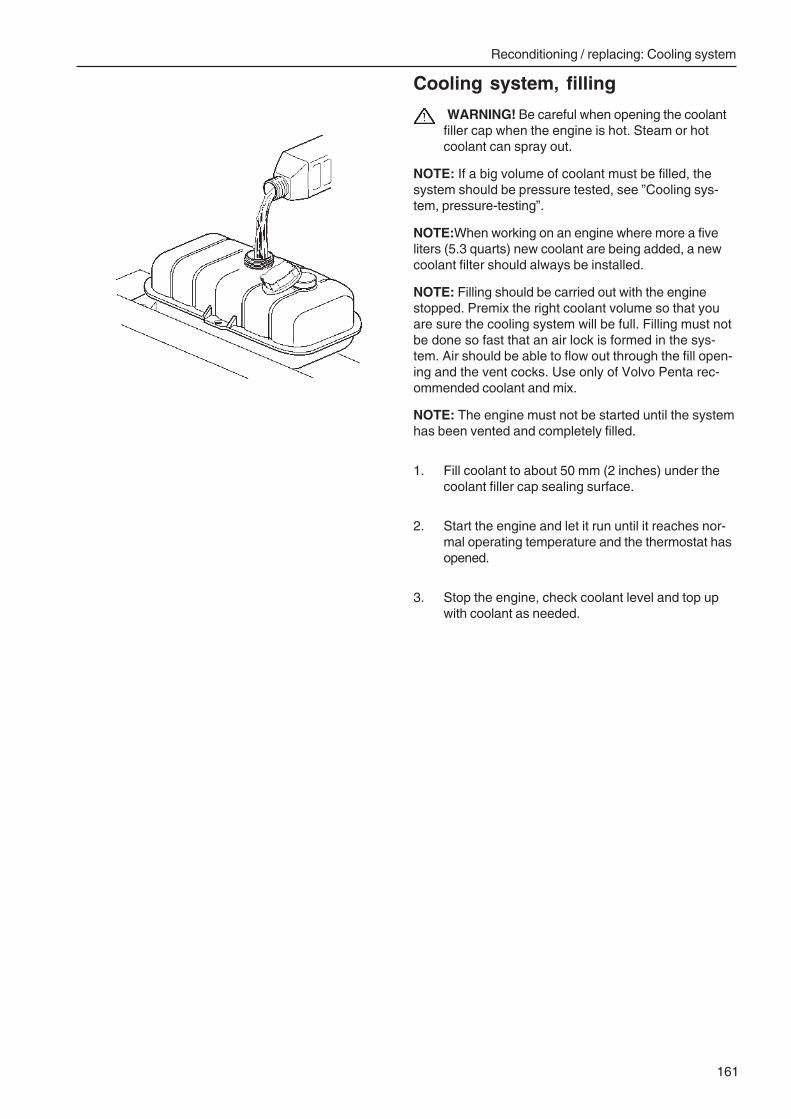
Reconditioning / replacing: Cooling system
161
Cooling system, filling
WARNING! Be careful when opening the coolantfiller cap when the engine is hot. Steam or hotcoolant can spray out.
NOTE: If a big volume of coolant must be filled, thesystem should be pressure tested, see ”Cooling sys-tem, pressure-testing”.
NOTE:When working on an engine where more a fiveliters (5.3 quarts) new coolant are being added, a newcoolant filter should always be installed.
NOTE: Filling should be carried out with the enginestopped. Premix the right coolant volume so that youare sure the cooling system will be full. Filling must notbe done so fast that an air lock is formed in the sys-tem. Air should be able to flow out through the fill open-ing and the vent cocks. Use only of Volvo Penta rec-ommended coolant and mix.
NOTE: The engine must not be started until the systemhas been vented and completely filled.
1. Fill coolant to about 50 mm (2 inches) under thecoolant filler cap sealing surface.
2. Start the engine and let it run until it reaches nor-mal operating temperature and the thermostat hasopened.
3. Stop the engine, check coolant level and top upwith coolant as needed.
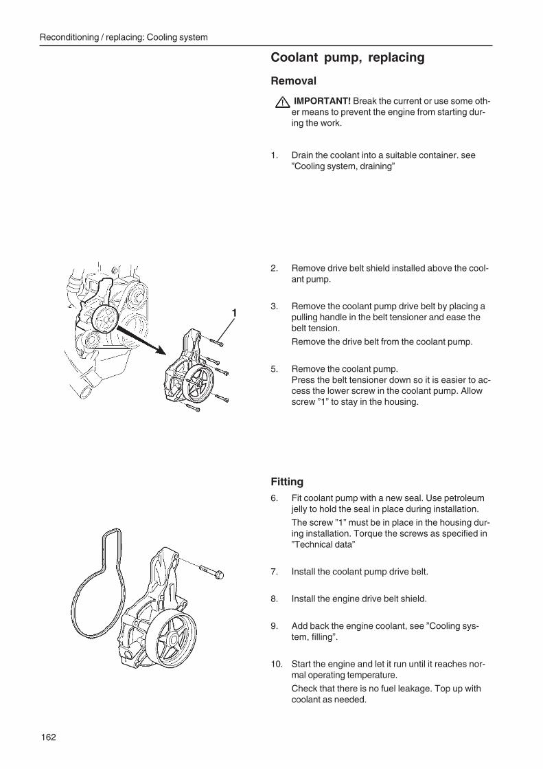
Reconditioning / replacing: Cooling system
162
Coolant pump, replacing
Removal
IMPORTANT! Break the current or use some oth-er means to prevent the engine from starting dur-ing the work.
1. Drain the coolant into a suitable container. see”Cooling system, draining”
2. Remove drive belt shield installed above the cool-ant pump.
3. Remove the coolant pump drive belt by placing apulling handle in the belt tensioner and ease thebelt tension.
Remove the drive belt from the coolant pump.
5. Remove the coolant pump.Press the belt tensioner down so it is easier to ac-cess the lower screw in the coolant pump. Allowscrew ”1” to stay in the housing.
Fitting6. Fit coolant pump with a new seal. Use petroleum
jelly to hold the seal in place during installation.
The screw ”1” must be in place in the housing dur-ing installation. Torque the screws as specified in”Technical data”
7. Install the coolant pump drive belt.
8. Install the engine drive belt shield.
9. Add back the engine coolant, see ”Cooling sys-tem, filling”.
10. Start the engine and let it run until it reaches nor-mal operating temperature.
Check that there is no fuel leakage. Top up withcoolant as needed.
1
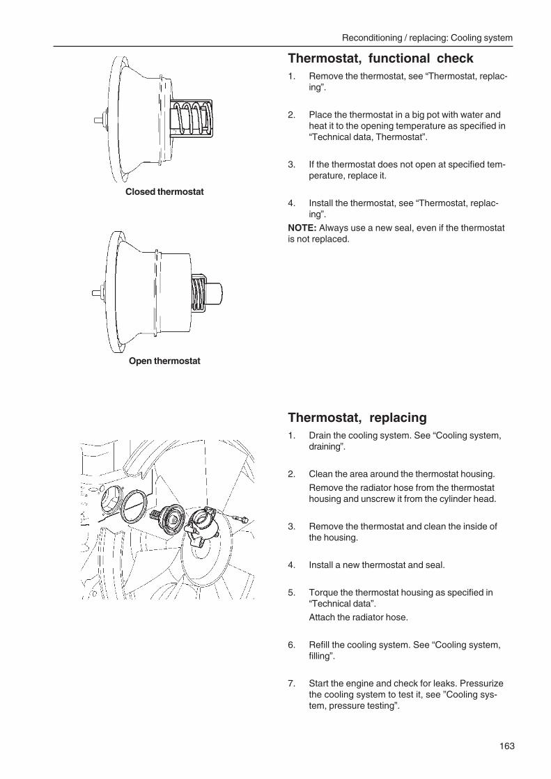
Reconditioning / replacing: Cooling system
163
Thermostat, functional check1. Remove the thermostat, see “Thermostat, replac-
ing”.
2. Place the thermostat in a big pot with water andheat it to the opening temperature as specified in“Technical data, Thermostat”.
3. If the thermostat does not open at specified tem-perature, replace it.
4. Install the thermostat, see “Thermostat, replac-ing”.
NOTE: Always use a new seal, even if the thermostatis not replaced.
Thermostat, replacing1. Drain the cooling system. See “Cooling system,
draining”.
2. Clean the area around the thermostat housing.
Remove the radiator hose from the thermostathousing and unscrew it from the cylinder head.
3. Remove the thermostat and clean the inside ofthe housing.
4. Install a new thermostat and seal.
5. Torque the thermostat housing as specified in“Technical data”.
Attach the radiator hose.
6. Refill the cooling system. See “Cooling system,filling”.
7. Start the engine and check for leaks. Pressurizethe cooling system to test it, see ”Cooling sys-tem, pressure testing”.
Closed thermostat
Open thermostat
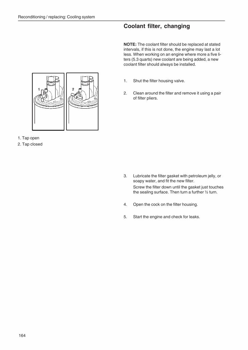
Reconditioning / replacing: Cooling system
164
Coolant filter, changing
NOTE: The coolant filter should be replaced at statedintervals, if this is not done, the engine may last a lotless. When working on an engine where more a five li-ters (5.3 quarts) new coolant are being added, a newcoolant filter should always be installed.
1. Shut the filter housing valve.
2. Clean around the filter and remove it using a pairof filter pliers.
1. Tap open
2. Tap closed
3. Lubricate the filter gasket with petroleum jelly, orsoapy water, and fit the new filter.
Screw the filter down until the gasket just touchesthe sealing surface. Then turn a further ½ turn.
4. Open the cock on the filter housing.
5. Start the engine and check for leaks.
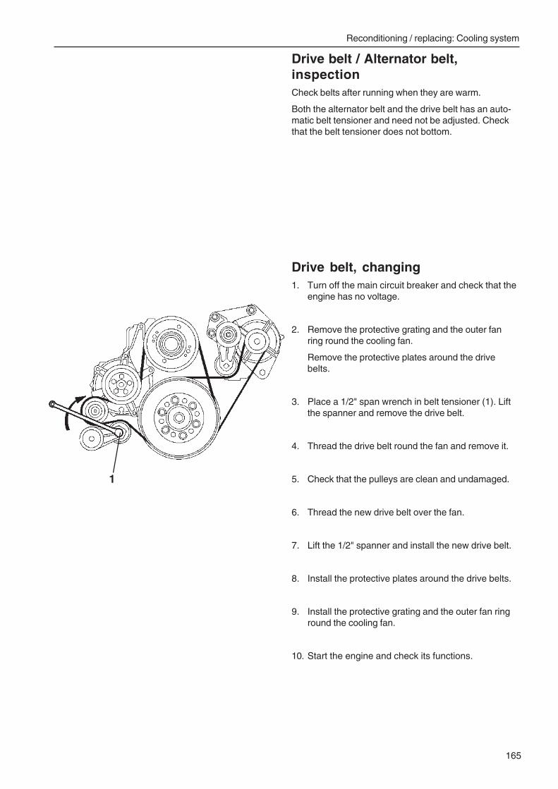
Reconditioning / replacing: Cooling system
165
Drive belt / Alternator belt,inspectionCheck belts after running when they are warm.
Both the alternator belt and the drive belt has an auto-matic belt tensioner and need not be adjusted. Checkthat the belt tensioner does not bottom.
Drive belt, changing1. Turn off the main circuit breaker and check that the
engine has no voltage.
2. Remove the protective grating and the outer fanring round the cooling fan.
Remove the protective plates around the drivebelts.
3. Place a 1/2" span wrench in belt tensioner (1). Liftthe spanner and remove the drive belt.
4. Thread the drive belt round the fan and remove it.
5. Check that the pulleys are clean and undamaged.
6. Thread the new drive belt over the fan.
7. Lift the 1/2" spanner and install the new drive belt.
8. Install the protective plates around the drive belts.
9. Install the protective grating and the outer fan ringround the cooling fan.
10. Start the engine and check its functions.
1
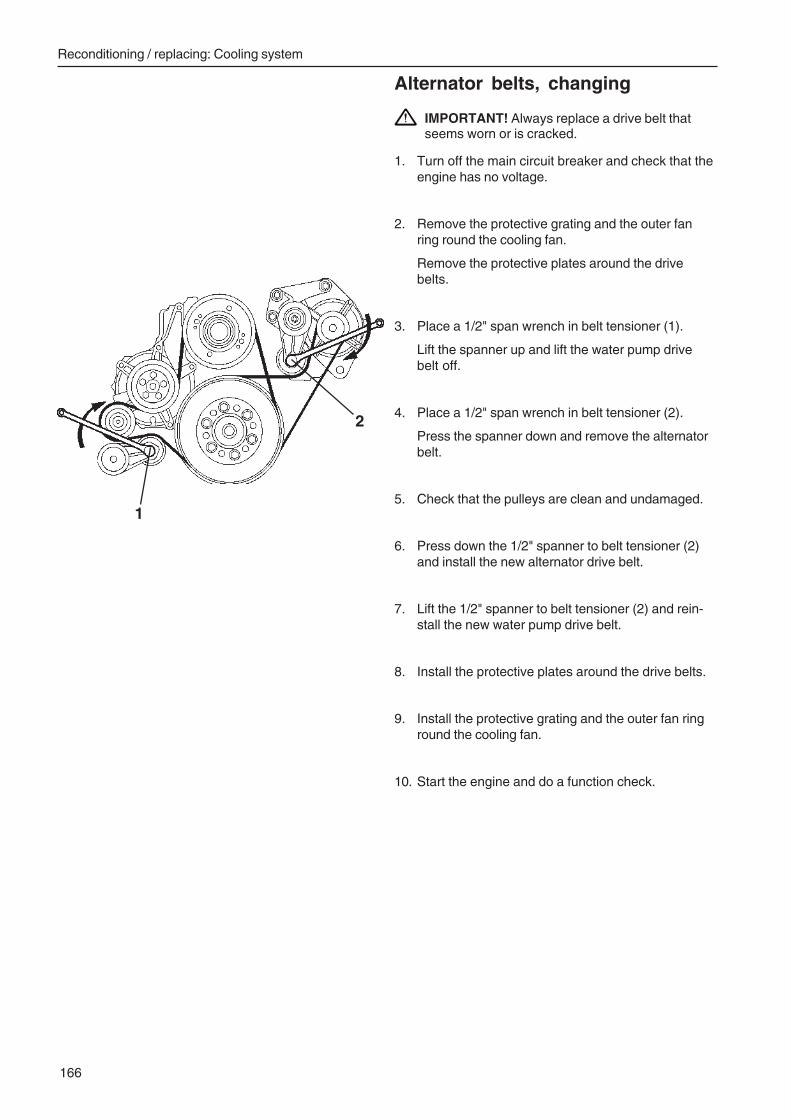
Reconditioning / replacing: Cooling system
166
Alternator belts, changing
IMPORTANT! Always replace a drive belt thatseems worn or is cracked.
1. Turn off the main circuit breaker and check that theengine has no voltage.
2. Remove the protective grating and the outer fanring round the cooling fan.
Remove the protective plates around the drivebelts.
3. Place a 1/2" span wrench in belt tensioner (1).
Lift the spanner up and lift the water pump drivebelt off.
4. Place a 1/2" span wrench in belt tensioner (2).
Press the spanner down and remove the alternatorbelt.
5. Check that the pulleys are clean and undamaged.
6. Press down the 1/2" spanner to belt tensioner (2)and install the new alternator drive belt.
7. Lift the 1/2" spanner to belt tensioner (2) and rein-stall the new water pump drive belt.
8. Install the protective plates around the drive belts.
9. Install the protective grating and the outer fan ringround the cooling fan.
10. Start the engine and do a function check.
1
2

Notes...........................................................................................................................................................................................
...........................................................................................................................................................................................
...........................................................................................................................................................................................
...........................................................................................................................................................................................
...........................................................................................................................................................................................
...........................................................................................................................................................................................
...........................................................................................................................................................................................
...........................................................................................................................................................................................
...........................................................................................................................................................................................
...........................................................................................................................................................................................
...........................................................................................................................................................................................
...........................................................................................................................................................................................
...........................................................................................................................................................................................
...........................................................................................................................................................................................
...........................................................................................................................................................................................
...........................................................................................................................................................................................
...........................................................................................................................................................................................
...........................................................................................................................................................................................
...........................................................................................................................................................................................
...........................................................................................................................................................................................
...........................................................................................................................................................................................
...........................................................................................................................................................................................
...........................................................................................................................................................................................
...........................................................................................................................................................................................
...........................................................................................................................................................................................
...........................................................................................................................................................................................
Report form
Do you have any complaints or other comments about this manual.Please make a copy of this page, write your comments down and sendthem to us. The address is at the bottom. We would prefer you to write inEnglish or Swedish.
From: ......................................................................
................................................................................
................................................................................
................................................................................
Refers to publication: ................................................................................................................................
Publication No.: .................................. Date of issue: ................................................................................
Proposal/motivation: .................................................................................................................................
.................................................................................................................................................................
.................................................................................................................................................................
.................................................................................................................................................................
.................................................................................................................................................................
.................................................................................................................................................................
.................................................................................................................................................................
.................................................................................................................................................................
.................................................................................................................................................................
Date: ..................................................................................
Signed: ..............................................................................
AB Volvo PentaTechnical Information
Dept. 42200SE-405 08 Göteborg
Sweden

7745
022
Eng
lish
07–
2004

Workshop Manual(Group 23) EMS 2
TAD940GE, TAD941GETAD940VE, TAD941VE, TAD942VE, TAD943VE

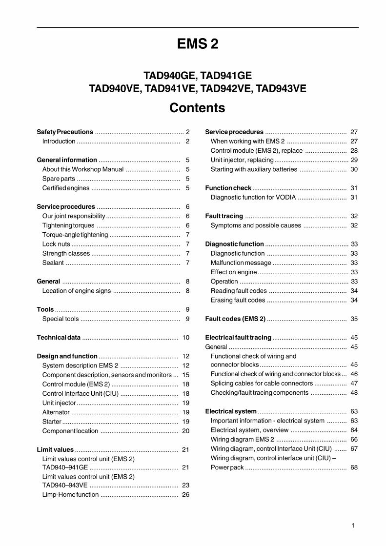
1
Contents
Safety Precautions ................................................. 2Introduction ......................................................... 2
General information ............................................. 5About this Workshop Manual .............................. 5Spare parts ......................................................... 5Certified engines ................................................. 5
Service procedures .............................................. 6Our joint responsibility ......................................... 6Tightening torques .............................................. 6Torque-angle tightening ....................................... 7Lock nuts ............................................................ 7Strength classes ................................................. 7Sealant ............................................................... 7
General ................................................................. 8Location of engine signs ..................................... 8
Tools ..................................................................... 9Special tools ....................................................... 9
Technical data ..................................................... 10
Design and function ............................................ 12System description EMS 2 ................................ 12Component description, sensors and monitors ... 15Control module (EMS 2) ..................................... 18Control Interface Unit (CIU) ................................ 18Unit injector ........................................................ 19Alternator ........................................................... 19Starter ................................................................ 19Component location ........................................... 20
Limit values ......................................................... 21Limit values control unit (EMS 2)TAD940–941GE ................................................. 21Limit values control unit (EMS 2)TAD940–943VE ................................................. 23Limp-Home function ........................................... 26
Service procedures ............................................. 27When working with EMS 2 ................................. 27Control module (EMS 2), replace ....................... 28Unit injector, replacing......................................... 29Starting with auxiliary batteries .......................... 30
Function check .................................................... 31Diagnostic function for VODIA ........................... 31
Fault tracing ........................................................ 32Symptoms and possible causes ........................ 32
Diagnostic function .............................................. 33Diagnostic function ............................................ 33Malfunction message ......................................... 33Effect on engine .................................................. 33Operation ............................................................ 33Reading fault codes ........................................... 34Erasing fault codes ............................................ 34
Fault codes (EMS 2) ............................................ 35
Electrical fault tracing ......................................... 45General ................................................................. 45
Functional check of wiring andconnector blocks ................................................ 45Functional check of wiring and connector blocks ... 46Splicing cables for cable connectors .................. 47Checking/fault tracing components .................... 48
Electrical system ................................................. 63Important information - electrical system ........... 63Electrical system, overview ............................... 64Wiring diagram EMS 2 ....................................... 66Wiring diagram, control Interface Unit (CIU) ....... 67Wiring diagram, control interface unit (CIU) –Power pack ........................................................ 68
EMS 2
TAD940GE, TAD941GETAD940VE, TAD941VE, TAD942VE, TAD943VE
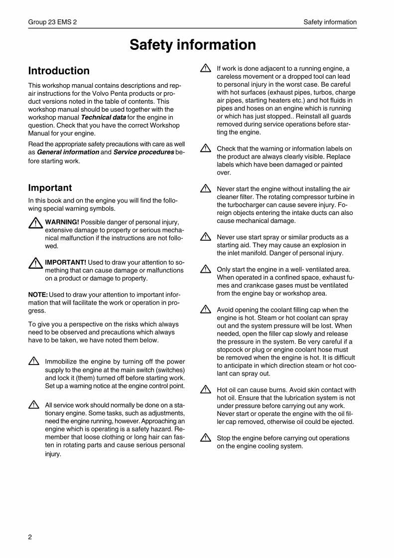
2
Group 23 EMS 2 Safety information
Safety information
IntroductionThis workshop manual contains descriptions and rep-air instructions for the Volvo Penta products or pro-duct versions noted in the table of contents. Thisworkshop manual should be used together with theworkshop manual Technical data for the engine inquestion. Check that you have the correct WorkshopManual for your engine.
Read the appropriate safety precautions with care as wellas General information and Service procedures be-fore starting work.
ImportantIn this book and on the engine you will find the follo-wing special warning symbols.
WARNING! Possible danger of personal injury,extensive damage to property or serious mecha-nical malfunction if the instructions are not follo-wed.
IMPORTANT! Used to draw your attention to so-mething that can cause damage or malfunctionson a product or damage to property.
NOTE:Used to draw your attention to important infor-mation that will facilitate the work or operation in pro-gress.
To give you a perspective on the risks which alwaysneed to be observed and precautions which alwayshave to be taken, we have noted them below.
Immobilize the engine by turning off the powersupply to the engine at the main switch (switches)and lock it (them) turned off before starting work.Set up a warning notice at the engine control point.
All service work should normally be done on a sta-tionary engine. Some tasks, such as adjustments,need the engine running, however. Approaching anengine which is operating is a safety hazard. Re-member that loose clothing or long hair can fas-ten in rotating parts and cause serious personalinjury.
If work is done adjacent to a running engine, acareless movement or a dropped tool can leadto personal injury in the worst case. Be carefulwith hot surfaces (exhaust pipes, turbos, chargeair pipes, starting heaters etc.) and hot fluids inpipes and hoses on an engine which is runningor which has just stopped.. Reinstall all guardsremoved during service operations before star-ting the engine.
Check that the warning or information labels onthe product are always clearly visible. Replacelabels which have been damaged or paintedover.
Never start the engine without installing the aircleaner filter. The rotating compressor turbine inthe turbocharger can cause severe injury. Fo-reign objects entering the intake ducts can alsocause mechanical damage.
Never use start spray or similar products as astarting aid. They may cause an explosion inthe inlet manifold. Danger of personal injury.
Only start the engine in a well- ventilated area.When operated in a confined space, exhaust fu-mes and crankcase gases must be ventilatedfrom the engine bay or workshop area.
Avoid opening the coolant filling cap when theengine is hot. Steam or hot coolant can sprayout and the system pressure will be lost. Whenneeded, open the filler cap slowly and releasethe pressure in the system. Be very careful if astopcock or plug or engine coolant hose mustbe removed when the engine is hot. It is difficultto anticipate in which direction steam or hot coo-lant can spray out.
Hot oil can cause burns. Avoid skin contact withhot oil. Ensure that the lubrication system is notunder pressure before carrying out any work.Never start or operate the engine with the oil fil-ler cap removed, otherwise oil could be ejected.
Stop the engine before carrying out operationson the engine cooling system.
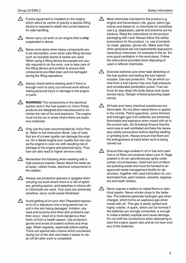
3
Group 23 EMS 2 Safety information
If extra equipment is installed on the enginewhich alters its centre of gravity a special liftingdevice is required to obtain the correct balancefor safe handling.
Never carry out work on an engine that is onlysuspended in ahoist.
Never work alone when heavy components areto be dismantled, even when safe lifting devisessuch as lockable blocks & tackle are used.When using a lifting device two people are usu-ally required to do the work, one to take care ofthe lifting device and another to ensure thatcomponents are lifted clear and not damagedduring the lifting operations.
Always check before starting work if there isenough room to carry out removal work withoutrisking personal injury or damage to the engineor parts.
WARNING! The components in the electricalsystem and in the fuel system on Volvo Pentaproducts are designed and manufactured to mi-nimise the risk of fire and explosion. The enginemust not be run in areas where there are explo-sive materials.
Only use the fuels recommended by Volvo Pen-ta. Refer to the Instruction Book. Use of fuelsthat are of a lower quality can damage the engi-ne. On a diesel engine poor quality fuel can cau-se the engine to over-rev with resulting risk ofdamage to the engine and personal injury. Poorfuel can also lead to higher service costs.
Remember the following when washing with ahigh pressure washer: Never direct the water jetat seals, rubber hoses, electrical components orthe radiator.
Always use protective glasses or goggles whencarrying out work where there is a risk of splint-ers, grinding sparks, acid splashes or where oth-er chemicals are used. Your eyes are extremelysensitive, injury could cause blindness!
Avoid getting oil on your skin! Repeated exposu-re to oil or exposure over a long period can re-sult in the skin being damaged. Irritation, dry-ness and eczema and other skin problems canthen occur. Used oil is more dangerous thanfresh oil from a health aspect. Use protectivegloves and avoid oil soaked clothes and shoprags. Wash regularly, especially before eating.There are special skin creams which counteractdrying out of the skin and make it easier to cle-an off dirt after work is completed.
Most chemicals intended for the product e.g.engine and transmission oils, glycol, petrol (ga-soline) and diesel oil, or chemicals for workshopuse e.g. degreasers, paints and solvents are ha-zardous. Read the instructions on the productpackaging with care! Always follow the safetyprecautions for the product, i.e. use of protecti-ve mask, glasses, gloves etc. Make sure thatother personnel are not inadvertently exposed tohazardous chemicals, for example in the air. En-sure good ventilation in the work place. Followthe instructions provided when disposing ofused or leftover chemicals.
Exercise extreme care when leak detecting onthe fuel system and testing the fuel injectornozzles. Use eye protection. The jet which co-mes from a fuel injector has very high pressureand considerable penetration power. Fuel canforce its way deep into body tissue and causesevere injury. Danger of blood poisoning (septi-cemia).
All fuels and many chemical substances areflammable. Do not allow naked flame or sparksin the vicinity. Petrol (gasoline), some thinnersand hydrogen gas from batteries are extremelyflammable and explosive when mixed with air inthe correct ratio. No Smoking! Ensure that thework area is well ventilated and take the neces-sary safety precautions before starting weldingor grinding work. Always ensure that there arefire extinguishers at hand when work is beingcarried out.
Ensure that rags soaked in oil or fuel and usedfuel or oil filters are properly taken care of. Ragssoaked in oil can spontaneously ignite undercertain circumstances. Used fuel and oil filtersare polluting waste and must be handed to anapproved waste management facility for de-struction, together with used lubrication oil, con-taminated fuel, paint residue, solvents, degreas-ers and wash residue.
Never expose a battery to naked flame or elec-trical sparks. Never smoke close to the batte-ries. The batteries generate hydrogen gas whencharged, which forms an explosive gas whenmixed with air. This gas is easily ignited andhighly volatile. A spark, which can be formed ifthe batteries are wrongly connected, is enoughto make a battery explode and cause damage.Do not shift the connections when attempting tostart the engine (spark risk) and do not lean overany of the batteries.
4
Group 23 EMS 2 Safety information
Always ensure that the Plus (positive) and Mi-nus (negative) battery cables are correctly in-stalled on the corresponding terminal posts onthe batteries. Incorrect installation can result inserious damage to the electrical equipment. Re-fer to the wiring diagram.
Always use protective goggles when chargingand handling the batteries. Battery electrolytecontains sulfuric acid which is highly corrosive.Should the battery electrolyte come into contactwith unprotected skin wash off immediatelyusing plenty of water and soap. If battery acidcomes in contact with the eyes, immediatelyflush with plenty of water and obtain medical as-sistance at once.
Turn the engine off and turn off the power at themain switch(es) before carrying out work on theelectrical system.
The clutch must be adjusted with the engineshut off.
Use the lifting eyes fitted on the engine whenlifting the drive unit. Always check that thelifting equipment used is in good condition andhas the load capacity to lift the engine (engineweight including gearbox, if fitted, and any extraequipment installed).
Use an adjustable lifting beam or lifting beamspecifically for the engine to raise the engine toensure safe handling and to avoid damagingengine parts installed on the top of the engine.All chains and cables should run parallel to eachother and as perpendicular as possible in rela-tion to the top of the engine.
© 2004 AB VOLVO PENTAWe reserve the right to make modifications without prior notice.
Printed on environmentally-friendly paper.
5
Group 23 EMS 2 General
General information
About this Workshop ManualThis Workshop Manual contains descriptions and ins-tructions for the repair of standard versions of engi-nes: TAD940GE, TAD941GE, TAD940VE,TAD941VE,TAD942VE, TAD943VE.
The workshop manual can illustrate tasks done onany of the engines noted above. This means that theillustrations and photographs which clarify certain de-tails might, in some cases, not correspond with otherengines. Repair methods are similar in all importantrespects, however. The Engine Designation and Engi-ne Numbers can be found on the product plate. See”Technical data TAD940GE, TAD941GE,TAD940VE,TAD941VE, TAD942VE, TAD943VE”.Please always include both the engine designationand the engine number in all correspondence.
The Workshop Manual is produced primarily for theuse of Volvo Penta workshops and service technici-ans. For this reason the manual presupposes a cer-tain basic knowledge and that the user can carry outthe mechanical/electrical work described to a generalstandard of engineering competence.
Volvo Penta constantly improves its products, so wereserve the right to make modifications without priornotification. All information in this manual is based onproduct data which was available up to the date onwhich the manual was printed. Any material changesintroduced into the product or service methods afterthis date are notified by means of Service Bulletins.
Spare partsSpare parts for the electrical and fuel systems aresubject to various national safety requirements. VolvoPenta Original Spare Parts meet these specifications.Any type of damage which is the result of using spareparts that are not original Volvo Penta parts for theproduct in question will not be covered under any war-ranty or guarantee provided by AB Volvo Penta.
Certified enginesThe manufacturer warrants that both new and current-ly operating engines that are certified to national andregional environmental regulations meet environmentalrequirements. The product must correspond to theengine that was approved during certification. The fol-lowing requirements for service and spare parts mustbe complied with, for Volvo Penta as a manufacturerto be responsible for ensuring that engines in usecomply with the stipulated environmental require-ments:
• Service and maintenance intervals recommendedby Volvo Penta must be followed.
• Only Volvo Penta Original Spare Parts intendedfor the certified engine version may be used.
• Service work that covers injection pumps, pumpsettings, and injectors must always be carried outby an authorized Volvo Penta workshop.
• The engine must not be converted or modified inany way, except for the accessories and servicekits which Volvo Penta has approved for the engi-ne.
• Installation changes to the exhaust pipe and theengine bay air inlet ducts (ventilation ducts) mustnot be done without further discussion, since thiscould affect exhaust emissions. No tamper-sealsmay be broken by unauthorized personnel.
IMPORTANT! When spare parts are needed,use only Volvo Penta Original Spares.
Use of non-original parts will result in ABVolvo Penta being unable to warrant thatthe engine corresponds to the certificatedengine version.
Any damage, injury and/or costs which arisedue to the use of non-original Volvo Penta spa-res for the product in question will not be com-pensated by Volvo Penta.
6
Group 23 EMS 2 Repair instructions
Repair instructionsThe working methods described in the Workshop Ma-nual apply to work carried out in a workshop. The eng-ine has been removed and is installed in an engine fix-ture. Unless otherwise stated reconditioning workwhich can be carried out with the engine in place fol-lows the same working method.
See chapter ”Safety information” where the meaningof the warning signs used in the manual are explainedin detail.
WARNING!
IMPORTANT!
NOTE!
are not comprehensive in any way, since we can notof course foresee everything, because service work isdone in highly varying circumstances. For this reason,all we can do is to point out the risks which we believecould occur due to incorrect work in a well-equippedworkshop, using work methods and tools tested byus.
All operations described in the Workshop Manual forwhich there are Volvo Penta Special Tools availableassume that these tools are used when carrying outthe repair. Volvo Penta Special Tools have been spe-cifically developed to ensure the most safe and ratio-nal working methods possible. It is therefore the re-sponsibility of anyone using other tools or other wor-king methods than we recommend to determine thatthere is no risk of personal injury or mechanical dama-ge or malfunction as a result.
In some cases special safety precautions and user ins-tructions may be required in order to use the tools andchemicals mentioned in the Workshop Manual. Theserules must always be observed, so there are no specialinstructions about this in the workshop manual.
By following these basic recommendations and usingcommon sense it is possible to avoid most of therisks involved in the work. A clean work place and aclean engine will eliminate many risks of personal inju-ry and engine malfunction.
Especially when working on the fuel system, enginelubrication system, air intake system, turbochargerunit, bearing seals and seals, it is extremely importantto avoid dirt or foreign objects entering the parts orsystems, since this can result in reduced service lifeor malfunctions.
Our common responsibilityEach engine consists of a large number of collabora-ting systems and components. Any deviation of acomponent from its technical specification can drama-tically increase the environmental impact of an other-wise good engine. For this reason, it is extremely im-portant that specified wear tolerances are maintained,that systems with adjustment facilities are correctlyadjusted and that Volvo Penta Original Spares areused for the engine. The stated service intervals inthe Maintenance Schedule must be observed.
Some systems, such as the components in the fuelsystem, require special expertise and special testingequipment for service and maintenance. Some compo-nents are sealed at the factory, for environmental rea-sons etc. Under no circumstances attempt to serviceor repair a sealed component unless the service techni-cian carrying out the work is authorized to do so.
Remember that most chemical products,incorrectly used, damage the environment. Volvo Pen-ta recommends the use of bio-degradable degreasingagents for all cleaning of engine components unlessotherwise stated in the Workshop Manual. Pay specialattention to make sure that oils and washing residueetc are handled correctly for destruction, and do notunintentionally end up in nature.
TorqueThe tightening torques for critical joints, which shouldbe tightened with a torque wrench, are listed in Tech-nical data,Tightening Torques”, and are noted in thetask descriptions in the manual. All torque specifica-tions apply to clean screws, screw heads and matingfaces. Torque data stated apply to lightly oiled or drythreads. Where grease, locking or sealing agents arerequired for screwed joints this is stated in both theoperation description and in ”Tightening Torques”.Where no torque is stated for a joint use the generaltorque shown in the following table. The torques sta-ted are a guide and the joint does not have to betightened using a torque wrench.
Dimension Tightening torque
Nm lbf.ft.
M5 6 4,4
M6 10 7,4
M8 25 18,4
M10 50 36,9
M12 80 59,0
M14 140 103,3
7
Group 23 EMS 2 Repair instructions
Torque-angle tighteningIn torque/angle tightening, the fastener is tightened tothe specified torque, and tightening then continues th-rough a pre-determined angle. Example: for 90° angletightening, the joint is turned a further 1/4 turn in onesequence, after the specified tightening torque hasbeen achieved.
Lock nutsDisassembled locknuts shall not be re-used, theyshall be replaced by new ones, since the locking pro-perties are impaired or lost when the nut is used seve-ral times. For lock nuts with a plastic insert such asNylock® the torque stated in the table is reduced if theNylock® nut has the same head height as a standardhexagonal nut without plastic insert. Reduce the tor-que by 25% for screw size 8 mm or larger. Where Ny-lock® nuts are higher, where the metallic thread is ofthe same height as a standard hexagonal nut, the tor-ques given in the as shown in table apply.
Strength classesScrews and nuts are sub-divided into differentstrength classes. The classification is shown by amarking on the screw head. Markings of a higher num-ber indicate stronger material. For example, a screwmarked 10-9 is stronger than one marked 8-8. For thisreason, it is important when fasteners are dismantled,that the screws are put back in the correct placeswhen they are re-installed. If a bolt must be replacedcheck in the spare parts catalogue to make sure thecorrect type is used.
SealantSeveral types of sealant and locking liquid are usedon the engines. The properties of the sealants differas they are intended for different strengths of faste-nings, temperature, resistance to oil and other chemi-cals, and also for different materials and gap thicknes-ses found in the engine.
To ensure service work is correctly carried out it is im-portant that the correct sealant and locking fluid typeis used on the joint where the agents are required.
In this Volvo Penta Workshop Manual the user will findthat each section where these agents are applied inproduction states which type was used on the engine.
For service work, an similar product from the samemanufacturer, or corresponding product with the samecharacteristics from another manufacturer, can beused.
When using sealants and locking fluids, make surethat mating surfaces are dry and free from oil, grease,paint, anti-corrosion agent and old sealant. Always fol-low the manufacturer’s instructions for use regardingtemperature range, curing time and any other instruc-tions for the product
Two different basic types of agent are used on theengine. These are:
1. RTV agent (Room Temperature Vulcanizing). Usedfor gaskets, sealing gasket joints or coating gaskets.RTV is visible when a part has been disassembled;old RTV must be removed before resealing the joint.
The following agents are of RTV-type: Loctite® 574,Volvo Penta 840879-1, Permatex® No. 3, Volvo Pen-ta 1161099-5, Permatex® Nr 77. Old sealant can beremoved using denatured alcohol in all cases.
2. Anaerobic agents. These agents cure in theabsence of air. These agents are used when two solidcomponents, i.e. cast components, are fitted togetherwithout a gasket. Common uses are also to lock andseal plugs, stud threads, taps, oil pressure monitorsetc. Hardened anaerobic preparations are glassy andfor this reason, the preparations are coloured to makethem visible. Cured anaerobic agents are extremelyresistant to solvents and the old agent cannot beremoved. When reinstalling the part, degrease it care-fully and then apply new sealant.
The following agents are anaerobic: Loctite® 572(white), Loctite® 241 (blue).
Notice: Loctite® is a registered trademark for the Loctite Corpo-ration.Permatex® is a registered trademark for the Permatex Corpora-tion.
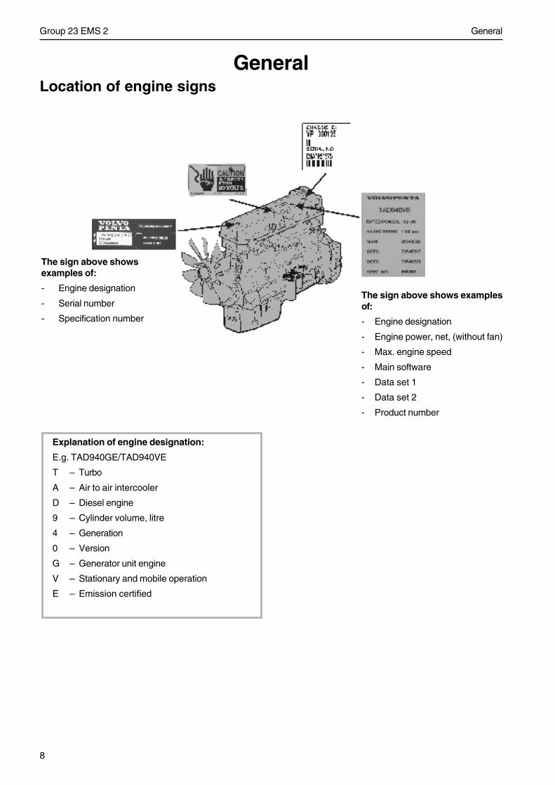
8
Group 23 EMS 2 General
Location of engine signsGeneral
Explanation of engine designation:
E.g. TAD940GE/TAD940VE
T – Turbo
A – Air to air intercooler
D – Diesel engine
9 – Cylinder volume, litre
4 – Generation
0 – Version
G – Generator unit engine
V – Stationary and mobile operation
E – Emission certified
The sign above showsexamples of:
- Engine designation
- Serial number
- Specification number
The sign above shows examplesof:
- Engine designation
- Engine power, net, (without fan)
- Max. engine speed
- Main software
- Data set 1
- Data set 2
- Product number
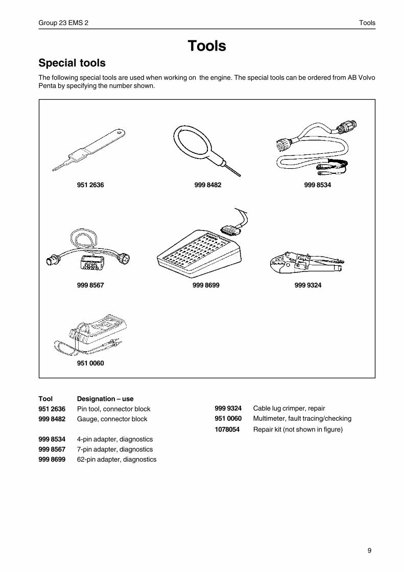
9
Group 23 EMS 2 Tools
ToolsSpecial tools
Tool Designation – use
951 2636 Pin tool, connector block
999 8482 Gauge, connector block
999 8534 4-pin adapter, diagnostics
999 8567 7-pin adapter, diagnostics
999 8699 62-pin adapter, diagnostics
951 2636 999 8482 999 8534
999 8567 999 8699 999 9324
999 9324 Cable lug crimper, repair
951 0060 Multimeter, fault tracing/checking
1078054 Repair kit (not shown in figure)
951 0060
The following special tools are used when working on the engine. The special tools can be ordered from AB VolvoPenta by specifying the number shown.
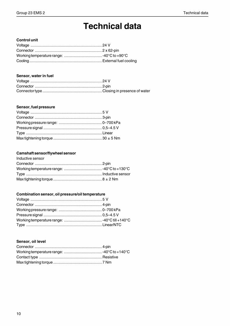
10
Group 23 EMS 2 Technical data
Technical dataControl unitVoltage .................................................................. 24 VConnector .............................................................. 2 x 62-pinWorking temperature range: ................................... -40°C to +90°CCooling ...................................................................External fuel cooling
Sensor, water in fuelVoltage .................................................................. 24 VConnector .............................................................. 2-pinConnector type .......................................................Closing in presence of water
Sensor, fuel pressureVoltage .................................................................. 5 VConnector .............................................................. 3-pinWorking pressure range: ........................................ 0–700 kPaPressure signal ...................................................... 0,5–4.5 VType ...................................................................... LinearMax tightening torque ............................................. 30 ± 5 Nm
Camshaft sensor/flywheel sensorInductive sensorConnector .............................................................. 2-pinWorking temperature range: ................................... -40°C to +130°CType ...................................................................... Inductive sensorMax tightening torque ............................................. 8 ± 2 Nm
Combination sensor, oil pressure/oil temperatureVoltage .................................................................. 5 VConnector .............................................................. 4-pinWorking pressure range: ........................................ 0–700 kPaPressure signal ...................................................... 0,5–4.5 VWorking temperature range: ................................... -40°C till +140°CType ...................................................................... Linear/NTC
Sensor, oil levelConnector .............................................................. 4-pinWorking temperature range: ................................... -40°C to +140°CContact type ..........................................................ResistiveMax tightening torque ............................................. 7 Nm
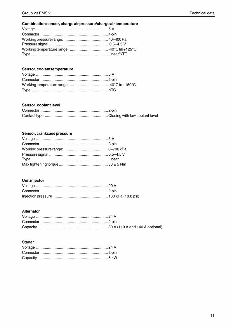
11
Group 23 EMS 2 Technical data
Combination sensor, charge air pressure/charge air temperatureVoltage .................................................................. 5 VConnector .............................................................. 4-pinWorking pressure range: ........................................ 40–400 PaPressure signal ...................................................... 0.5–4.5 VWorking temperature range: ................................... -40°C till +125°CType ...................................................................... Linear/NTC
Sensor, coolant temperatureVoltage .................................................................. 5 VConnector .............................................................. 2-pinWorking temperature range: ................................... -40°C to +150°CType ......................................................................NTC
Sensor, coolant levelConnector .............................................................. 2-pinContact type ..........................................................Closing with low coolant level
Sensor, crankcase pressureVoltage .................................................................. 5 VConnector .............................................................. 3-pinWorking pressure range: ........................................ 0–700 kPaPressure signal ...................................................... 0,5–4.5 VType ...................................................................... LinearMax tightening torque ............................................. 30 ± 5 Nm
Unit injectorVoltage .................................................................. 90 VConnector .............................................................. 2-pinInjection pressure................................................... 180 kPa (18.8 psi)
AlternatorVoltage .................................................................. 24 VConnector .............................................................. 2-pinCapacity ................................................................ 80 A (110 A and 140 A optional)
StarterVoltage .................................................................. 24 VConnector .............................................................. 2-pinCapacity ................................................................ 6 kW
12
Group 23 EMS 2 Design and function
Design and function
The EMS 2-systemEMS 2 stands for ”Engine Management System” and is an electronic system with CAN communications (Control-ler Area Network) for control of diesel engines. The system has been developed by Volvo Penta and includes fuelcontrol and diagnostic function. The system consists of a control module, six unit injectors, a number of sensorsthat supply the control module with measurements, sockets for diagnosis and functional checks. The engine canbe connected to a communication interface that consists of a CAN link and a serial link and to a Control InterfaceUnit (CIU) that interfaces with the driver’s position.
CAN (Controller Area Network)
The CAN J1939 link handles allcommunication between the engine control moduleEMS 2 and the CIU, in addition to the diagnostics thatare handled by the so called J1708/J1587 link. TheCAN link is much faster than the J1708/J1587 link.The CAN link has been prepared to connect to othercomponents with SAE J1939 protocol such as instru-ment panels and transmissions.
If, for some reason, a fault develops on the CAN link,signals for the rpm-potentiometer and the start andstop knobs are taken over by the J1708/J1587 link.However, instrument and indicator lamps are comple-tely turned off. If faults develop on both links, the GEand Power Pack engines maintain the same rpm whileVE engines slow to idle. The only way to shut off theengine in this case is to use the auxiliary stop (AUX-STOP) placed on the engine’s left side.
CIU (Control Interface Unit)
The CIU is a ”translator” between the CAN bus andthe customer’s own control panel. This unit has twoserial communication links, one fast and one slow.The fast one is a CAN link that features a bus speedof 250 Kbit/s. All data regarding instruments, indicatorlamps, contacts and potentiometers are controlled bythis bus. The slower J1708/J1587 link handles diag-nostic information for, among other things, the flas-hing code. The diagnosis tool VODIA also uses theJ1708/J1587 link to communicate with the system.
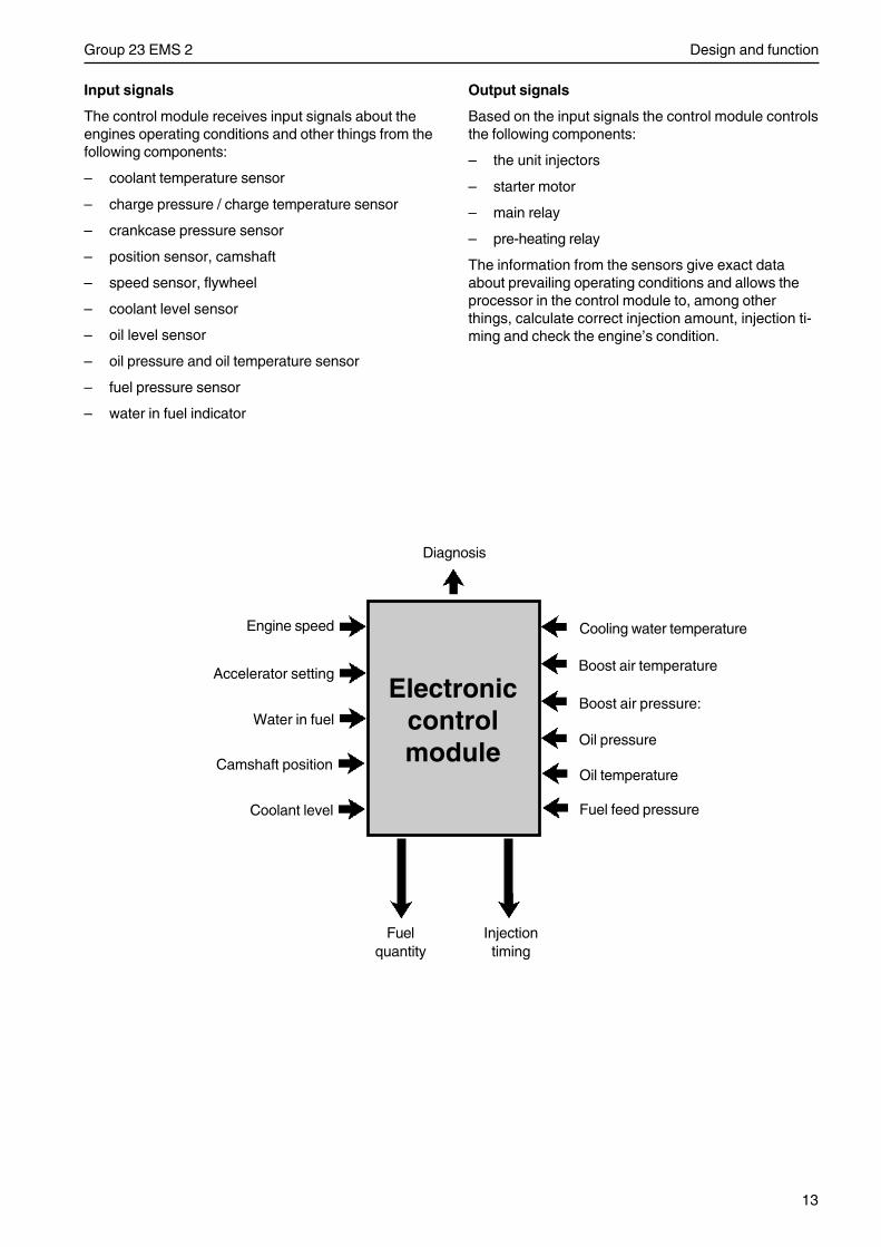
13
Group 23 EMS 2 Design and function
Input signals
The control module receives input signals about theengines operating conditions and other things from thefollowing components:
– coolant temperature sensor
– charge pressure / charge temperature sensor
– crankcase pressure sensor
– position sensor, camshaft
– speed sensor, flywheel
– coolant level sensor
– oil level sensor
– oil pressure and oil temperature sensor
– fuel pressure sensor
– water in fuel indicator
Output signals
Based on the input signals the control module controlsthe following components:
– the unit injectors
– starter motor
– main relay
– pre-heating relay
The information from the sensors give exact dataabout prevailing operating conditions and allows theprocessor in the control module to, among otherthings, calculate correct injection amount, injection ti-ming and check the engine’s condition.
Cooling water temperature
Boost air temperature
Boost air pressure:
Oil pressure
Oil temperature
Fuel feed pressure
Engine speed
Accelerator setting
Water in fuel
Diagnosis
Electroniccontrolmodule
Injectiontiming
Fuelquantity
Camshaft position
Coolant level
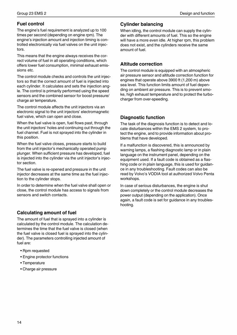
14
Group 23 EMS 2 Design and function
Fuel controlThe engine’s fuel requirement is analyzed up to 100times per second (depending on engine rpm). Theengine’s injection amount and injection timing is con-trolled electronically via fuel valves on the unit injec-tors.
This means that the engine always receives the cor-rect volume of fuel in all operating conditions, whichoffers lower fuel consumption, minimal exhaust emis-sions etc.
The control module checks and controls the unit injec-tors so that the correct amount of fuel is injected intoeach cylinder. It calculates and sets the injection ang-le. The control is primarily performed using the speedsensors and the combined sensor for boost pressure/charge air temperature.
The control module affects the unit injectors via anelectronic signal to the unit injectors’ electromagneticfuel valve, which can open and close.
When the fuel valve is open, fuel flows past, throughthe unit injectors’ holes and continuing out through thefuel channel. Fuel is not sprayed into the cylinder inthis position.
When the fuel valve closes, pressure starts to buildfrom the unit injector’s mechanically operated pumpplunger. When sufficient pressure has developed, fuelis injected into the cylinder via the unit injector’s injec-tor section.
The fuel valve is re-opened and pressure in the unitinjector decreases at the same time as the fuel injec-tion to the cylinder stops.
In order to determine when the fuel valve shall open orclose, the control module has access to signals fromsensors and switch contacts.
Calculating amount of fuelThe amount of fuel that is sprayed into a cylinder iscalculated by the control module. The calculation de-termines the time that the fuel valve is closed (whenthe fuel valve is closed fuel is sprayed into the cylin-der). The parameters controlling injected amount offuel are:
• Rpm requested
• Engine protector functions
• Temperature
• Charge air pressure
Cylinder balancingWhen idling, the control module can supply the cylin-der with different amounts of fuel. This so the enginewill have a more even idle. At higher rpm, this problemdoes not exist, and the cylinders receive the sameamount of fuel.
Altitude correctionThe control module is equipped with an atmosphericair pressure sensor and altitude correction function forengines that operate above 3900 ft (1,200 m) abovesea level. This function limits amount of fuel depen-ding on ambient air pressure. This is to prevent smo-ke, high exhaust temperature and to protect the turbo-charger from over-speeding.
Diagnostic functionThe task of the diagnosis function is to detect and lo-cate disturbances within the EMS 2 system, to pro-tect the engine, and to provide information about pro-blems that have developed.
If a malfunction is discovered, this is announced bywarning lamps, a flashing diagnostic lamp or in plainlanguage on the instrument panel, depending on theequipment used. If a fault code is obtained as a flas-hing code or in plain language, this is used for guidan-ce in any troubleshooting. Fault codes can also beread by Volvo’s VODIA tool at authorized Volvo Pentaworkshops.
In case of serious disturbances, the engine is shutdown completely or the control module decreases thepower output (depending on the application). Onceagain, a fault code is set for guidance in any troubles-hooting.
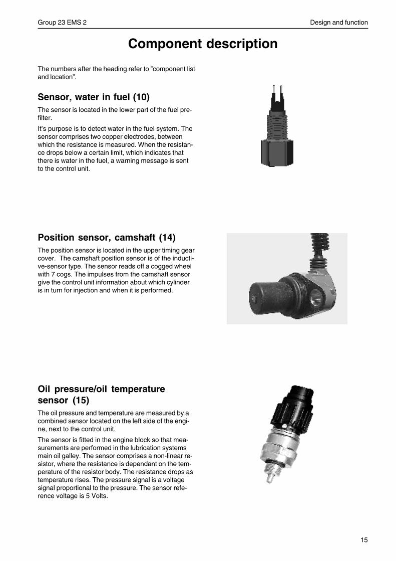
15
Group 23 EMS 2 Design and function
Component description
Position sensor, camshaft (14)The position sensor is located in the upper timing gearcover. The camshaft position sensor is of the inducti-ve-sensor type. The sensor reads off a cogged wheelwith 7 cogs. The impulses from the camshaft sensorgive the control unit information about which cylinderis in turn for injection and when it is performed.
Oil pressure/oil temperaturesensor (15)The oil pressure and temperature are measured by acombined sensor located on the left side of the engi-ne, next to the control unit.
The sensor is fitted in the engine block so that mea-surements are performed in the lubrication systemsmain oil galley. The sensor comprises a non-linear re-sistor, where the resistance is dependant on the tem-perature of the resistor body. The resistance drops astemperature rises. The pressure signal is a voltagesignal proportional to the pressure. The sensor refe-rence voltage is 5 Volts.
The numbers after the heading refer to ”component listand location”.
Sensor, water in fuel (10)The sensor is located in the lower part of the fuel pre-filter.
It’s purpose is to detect water in the fuel system. Thesensor comprises two copper electrodes, betweenwhich the resistance is measured. When the resistan-ce drops below a certain limit, which indicates thatthere is water in the fuel, a warning message is sentto the control unit.
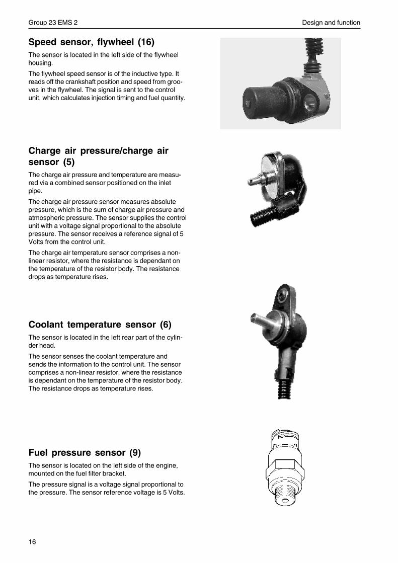
16
Group 23 EMS 2 Design and function
Coolant temperature sensor (6)The sensor is located in the left rear part of the cylin-der head.
The sensor senses the coolant temperature andsends the information to the control unit. The sensorcomprises a non-linear resistor, where the resistanceis dependant on the temperature of the resistor body.The resistance drops as temperature rises.
Charge air pressure/charge airsensor (5)The charge air pressure and temperature are measu-red via a combined sensor positioned on the inletpipe.
The charge air pressure sensor measures absolutepressure, which is the sum of charge air pressure andatmospheric pressure. The sensor supplies the controlunit with a voltage signal proportional to the absolutepressure. The sensor receives a reference signal of 5Volts from the control unit.
The charge air temperature sensor comprises a non-linear resistor, where the resistance is dependant onthe temperature of the resistor body. The resistancedrops as temperature rises.
Speed sensor, flywheel (16)The sensor is located in the left side of the flywheelhousing.
The flywheel speed sensor is of the inductive type. Itreads off the crankshaft position and speed from groo-ves in the flywheel. The signal is sent to the controlunit, which calculates injection timing and fuel quantity.
Fuel pressure sensor (9)The sensor is located on the left side of the engine,mounted on the fuel filter bracket.
The pressure signal is a voltage signal proportional tothe pressure. The sensor reference voltage is 5 Volts.
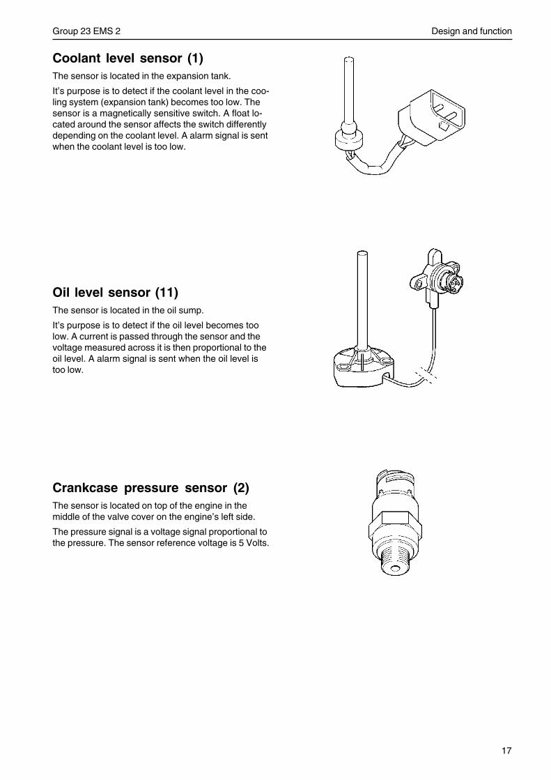
17
Group 23 EMS 2 Design and function
Coolant level sensor (1)The sensor is located in the expansion tank.
It’s purpose is to detect if the coolant level in the coo-ling system (expansion tank) becomes too low. Thesensor is a magnetically sensitive switch. A float lo-cated around the sensor affects the switch differentlydepending on the coolant level. A alarm signal is sentwhen the coolant level is too low.
Oil level sensor (11)The sensor is located in the oil sump.
It’s purpose is to detect if the oil level becomes toolow. A current is passed through the sensor and thevoltage measured across it is then proportional to theoil level. A alarm signal is sent when the oil level istoo low.
Crankcase pressure sensor (2)The sensor is located on top of the engine in themiddle of the valve cover on the engine’s left side.
The pressure signal is a voltage signal proportional tothe pressure. The sensor reference voltage is 5 Volts.
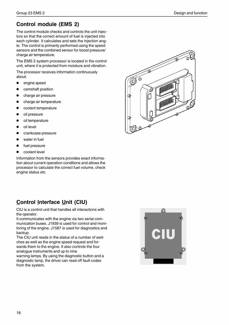
18
Group 23 EMS 2 Design and function
Control module (EMS 2)The control module checks and controls the unit injec-tors so that the correct amount of fuel is injected intoeach cylinder. It calculates and sets the injection ang-le. The control is primarily performed using the speedsensors and the combined sensor for boost pressure/charge air temperature.
The EMS 2 system processor is located in the controlunit, where it is protected from moisture and vibration.
The processor receives information continuouslyabout:
• engine speed
• camshaft position
• charge air pressure
• charge air temperature
• coolant temperature
• oil pressure
• oil temperature
• oil level
• crankcase pressure
• water in fuel
• fuel pressure
• coolant level
Information from the sensors provides exact informa-tion about current operation conditions and allows theprocessor to calculate the correct fuel volume, checkengine status etc.
Control Interface Unit (CIU)CIU is a control unit that handles all interactions withthe operator.It communicates with the engine via two serial com-munication buses. J1939 is used for control and moni-toring of the engine. J1587 is used for diagnostics andbackup.The CIU unit reads in the status of a number of swit-ches as well as the engine speed request and for-wards them to the engine. It also controls the fouranalogue instruments and up to ninewarning lamps. By using the diagnostic button and adiagnostic lamp, the driver can read off fault codesfrom the system.
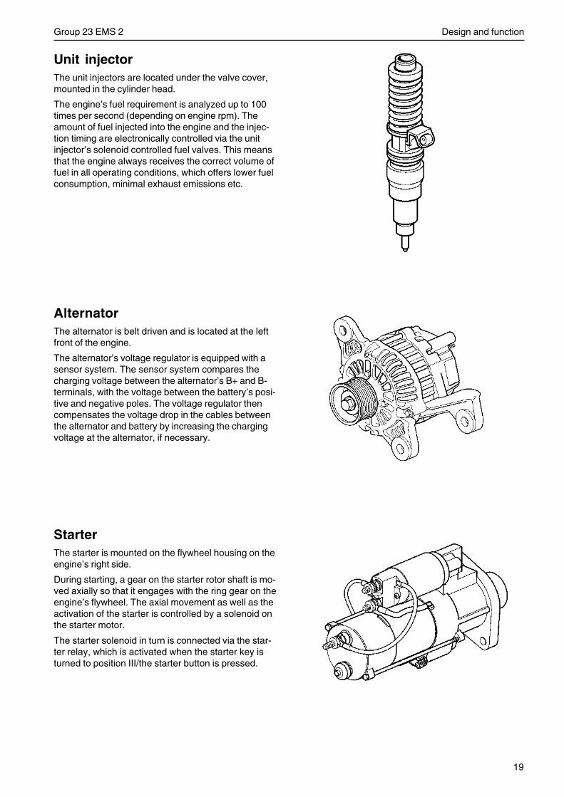
19
Group 23 EMS 2 Design and function
Unit injectorThe unit injectors are located under the valve cover,mounted in the cylinder head.
The engine’s fuel requirement is analyzed up to 100times per second (depending on engine rpm). Theamount of fuel injected into the engine and the injec-tion timing are electronically controlled via the unitinjector’s solenoid controlled fuel valves. This meansthat the engine always receives the correct volume offuel in all operating conditions, which offers lower fuelconsumption, minimal exhaust emissions etc.
AlternatorThe alternator is belt driven and is located at the leftfront of the engine.
The alternator’s voltage regulator is equipped with asensor system. The sensor system compares thecharging voltage between the alternator’s B+ and B-terminals, with the voltage between the battery’s posi-tive and negative poles. The voltage regulator thencompensates the voltage drop in the cables betweenthe alternator and battery by increasing the chargingvoltage at the alternator, if necessary.
StarterThe starter is mounted on the flywheel housing on theengine’s right side.
During starting, a gear on the starter rotor shaft is mo-ved axially so that it engages with the ring gear on theengine’s flywheel. The axial movement as well as theactivation of the starter is controlled by a solenoid onthe starter motor.
The starter solenoid in turn is connected via the star-ter relay, which is activated when the starter key isturned to position III/the starter button is pressed.
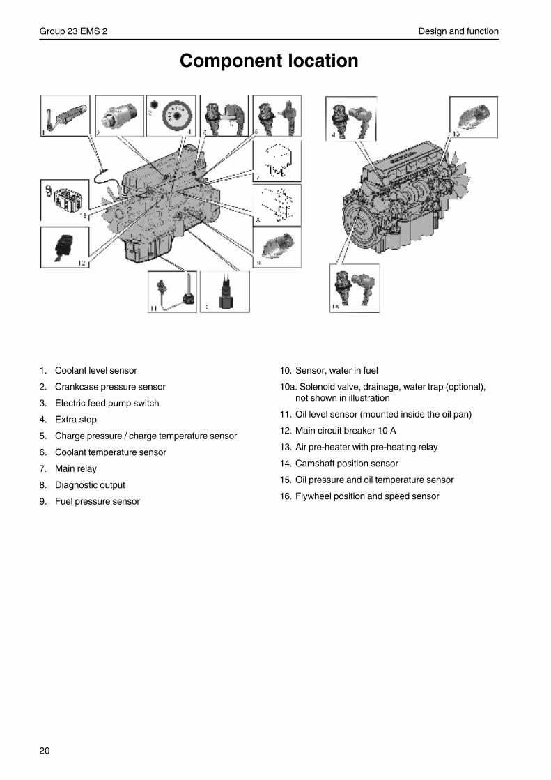
20
Group 23 EMS 2 Design and function
Component location
1. Coolant level sensor
2. Crankcase pressure sensor
3. Electric feed pump switch
4. Extra stop
5. Charge pressure / charge temperature sensor
6. Coolant temperature sensor
7. Main relay
8. Diagnostic output
9. Fuel pressure sensor
10. Sensor, water in fuel
10a. Solenoid valve, drainage, water trap (optional),not shown in illustration
11. Oil level sensor (mounted inside the oil pan)
12. Main circuit breaker 10 A
13. Air pre-heater with pre-heating relay
14. Camshaft position sensor
15. Oil pressure and oil temperature sensor
16. Flywheel position and speed sensor
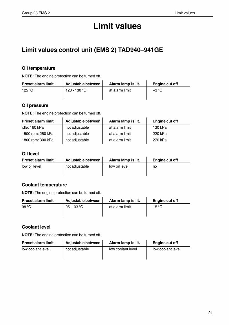
21
Group 23 EMS 2 Limit values
Limit values
Limit values control unit (EMS 2) TAD940–941GE
Oil temperature
NOTE: The engine protection can be turned off.
Preset alarm limit Adjustable between Alarm lamp is lit. Engine cut off
125 °C 120 - 130 °C at alarm limit +3 °C
Oil pressure
NOTE: The engine protection can be turned off.
Preset alarm limit Adjustable between Alarm lamp is lit. Engine cut off
idle: 160 kPa not adjustable at alarm limit 130 kPa
1500 rpm: 250 kPa not adjustable at alarm limit 220 kPa
1800 rpm: 300 kPa not adjustable at alarm limit 270 kPa
Oil levelPreset alarm limit Adjustable between Alarm lamp is lit. Engine cut off
low oil level not adjustable low oil level no
Coolant temperature
NOTE: The engine protection can be turned off.
Preset alarm limit Adjustable between Alarm lamp is lit. Engine cut off
98 °C 95 -103 °C at alarm limit +5 °C
Coolant level
NOTE: The engine protection can be turned off.
Preset alarm limit Adjustable between Alarm lamp is lit. Engine cut off
low coolant level not adjustable low coolant level low coolant level
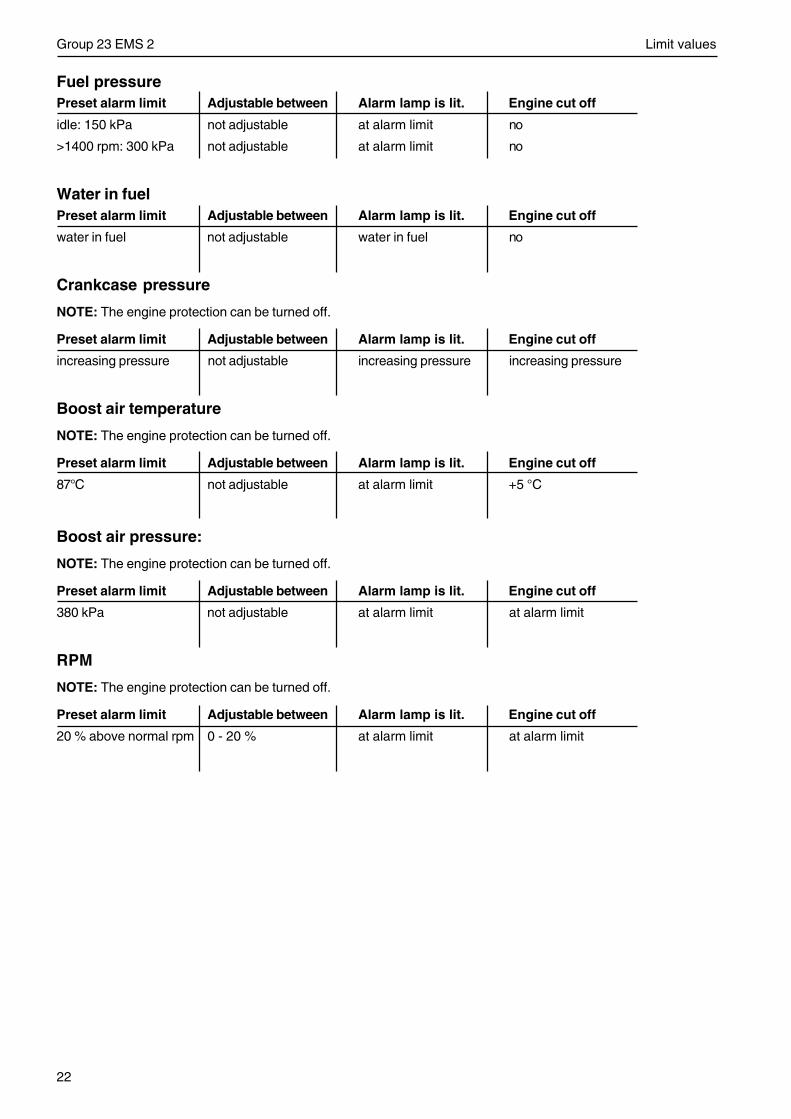
22
Group 23 EMS 2 Limit values
Fuel pressurePreset alarm limit Adjustable between Alarm lamp is lit. Engine cut off
idle: 150 kPa not adjustable at alarm limit no
>1400 rpm: 300 kPa not adjustable at alarm limit no
Water in fuelPreset alarm limit Adjustable between Alarm lamp is lit. Engine cut off
water in fuel not adjustable water in fuel no
Crankcase pressure
NOTE: The engine protection can be turned off.
Preset alarm limit Adjustable between Alarm lamp is lit. Engine cut off
increasing pressure not adjustable increasing pressure increasing pressure
Boost air temperature
NOTE: The engine protection can be turned off.
Preset alarm limit Adjustable between Alarm lamp is lit. Engine cut off
87°C not adjustable at alarm limit +5 °C
Boost air pressure:
NOTE: The engine protection can be turned off.
Preset alarm limit Adjustable between Alarm lamp is lit. Engine cut off
380 kPa not adjustable at alarm limit at alarm limit
RPM
NOTE: The engine protection can be turned off.
Preset alarm limit Adjustable between Alarm lamp is lit. Engine cut off
20 % above normal rpm 0 - 20 % at alarm limit at alarm limit
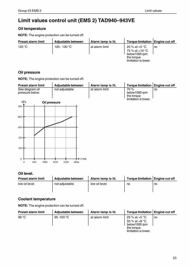
23
Group 23 EMS 2 Limit values
Limit values control unit (EMS 2) TAD940–943VE
Oil temperature
NOTE: The engine protection can be turned off.
Preset alarm limit Adjustable between Alarm lamp is lit. Torque limitation Engine cut off
125 °C 120 - 130 °C at alarm limit 25 % at +5 °C no75 % at +10 °Cbelow1000 rpmthe torquelimitation is lower.
Oil pressure
NOTE: The engine protection can be turned off.
Preset alarm limit Adjustable between Alarm lamp is lit. Torque limitation Engine cut offSee diagram oil not adjustable at alarm limit 70 % nopressure below. below1000 rpm
the torquelimitation is lower.
Oil level.Preset alarm limit Adjustable between Alarm lamp is lit. Torque limitation Engine cut off
low oil level not adjustable low oil level no no
Coolant temperature
NOTE: The engine protection can be turned off.
Preset alarm limit Adjustable between Alarm lamp is lit. Torque limitation Engine cut off
98 °C 95 -103 °C at alarm limit 25 % at +5 °C no50 % at +8 °Cbelow1000 rpmthe torquelimitation is lower.
Oil pressure
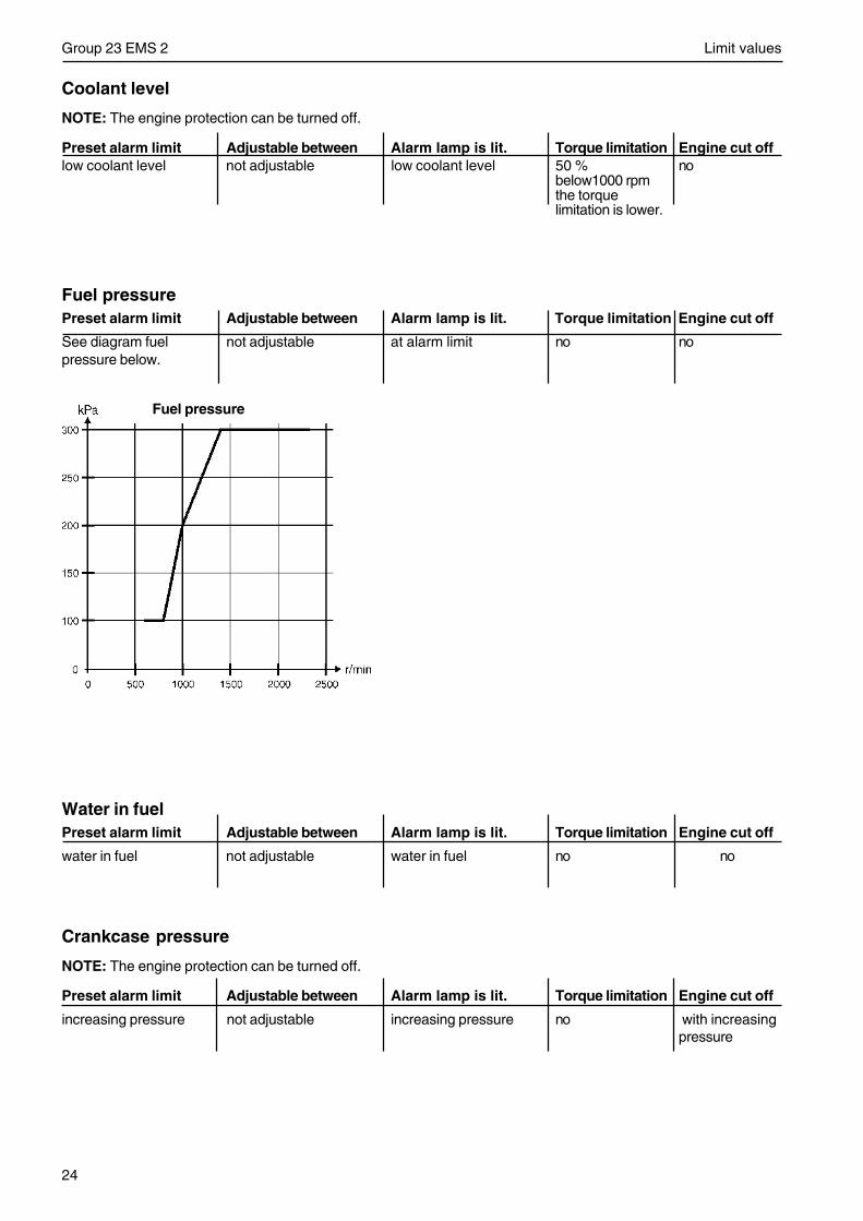
24
Group 23 EMS 2 Limit values
Coolant level
NOTE: The engine protection can be turned off.
Preset alarm limit Adjustable between Alarm lamp is lit. Torque limitation Engine cut offlow coolant level not adjustable low coolant level 50 % no
below1000 rpmthe torquelimitation is lower.
Fuel pressurePreset alarm limit Adjustable between Alarm lamp is lit. Torque limitation Engine cut off
See diagram fuel not adjustable at alarm limit no nopressure below.
Water in fuelPreset alarm limit Adjustable between Alarm lamp is lit. Torque limitation Engine cut off
water in fuel not adjustable water in fuel no no
Crankcase pressure
NOTE: The engine protection can be turned off.
Preset alarm limit Adjustable between Alarm lamp is lit. Torque limitation Engine cut off
increasing pressure not adjustable increasing pressure no with increasingpressure
Fuel pressure
25
Group 23 EMS 2 Limit values
Boost air temperature
NOTE: The engine protection can be turned off.
Preset alarm limit Adjustable between Alarm lamp is lit. Torque limitation Engine cut off
80°C not adjustable at alarm limit 0 % at +10 °C no50 % at +15 °C70 % at +25 °Cbelow 1000 rpmthe torquelimitation is lower.
Boost air pressure:
NOTE: The engine protection can be turned off.
Preset alarm limit Adjustable between Alarm lamp is lit. Torque limitation Engine cut off
325 kPa not adjustable at alarm limit 75 % at +25 kPa no
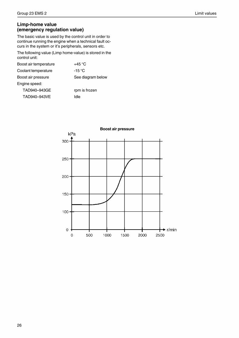
26
Group 23 EMS 2 Limit values
Limp-home value(emergency regulation value)The basic value is used by the control unit in order tocontinue running the engine when a technical fault oc-curs in the system or it’s peripherals, sensors etc.
The following value (Limp home-value) is stored in thecontrol unit:
Boost air temperature +45 °C
Coolant temperature -15 °C
Boost air pressure See diagram below
Engine speed:
TAD940–943GE rpm is frozen
TAD940–943VE Idle
Boost air pressure
27
Group 23 EMS 2 Repair instructions
Repair instructions
When working with EMS 2 systemFollow the instructions below so as not to damage the EMS 2-system control unit:
• Never switch off main power while the engine is running.
• Never disconnect a battery cable while the engine is running.
• When fast charging the batteries, turn off the main switch or disconnect one of the battery cables.The main switch does not need to be turned off during normal charging.
• Only batteries may be used for starting assistance. Starting boosters can generate excessive voltages anddamage the control units.
• Disconnect power to the EMS 2-system before removing the two 62-pin connectors from the control unit.
• If damage to the cable harness is detected, the 62-pin connectors on the control unit must be removed.
IMPORTANT! Disconnect the 62-pin connectors from the control unit if you are about to perform welding.
• Make sure that the connector pins are not contaminated with oil or other liquids while disconnected.Otherwise a contact problem may arise or the oil may run down inside to the pressure sensitive membraneand cause a misreading.
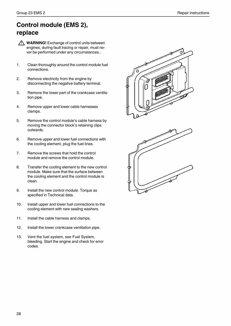
28
Group 23 EMS 2 Repair instructions
Control module (EMS 2),replace
WARNING! Exchange of control units betweenengines, during fault tracing or repair, must ne-ver be performed under any circumstances..
1. Clean thoroughly around the control module fuelconnections.
2. Remove electricity from the engine bydisconnecting the negative battery terminal.
3. Remove the lower part of the crankcase ventila-tion pipe.
4. Remove upper and lower cable harnessesclamps.
5. Remove the control module’s cable harness bymoving the connector block’s retaining clipsoutwards.
6. Remove upper and lower fuel connections withthe cooling element, plug the fuel lines.
7. Remove the screws that hold the controlmodule and remove the control module.
8. Transfer the cooling element to the new controlmodule. Make sure that the surface betweenthe cooling element and the control module isclean.
9. Install the new control module. Torque asspecified in Technical data.
10. Install upper and lower fuel connections to thecooling element with new sealing washers.
11. Install the cable harness and clamps.
12. Install the lower crankcase ventilation pipe.
13. Vent the fuel system, see Fuel System,bleeding. Start the engine and check for errorcodes.
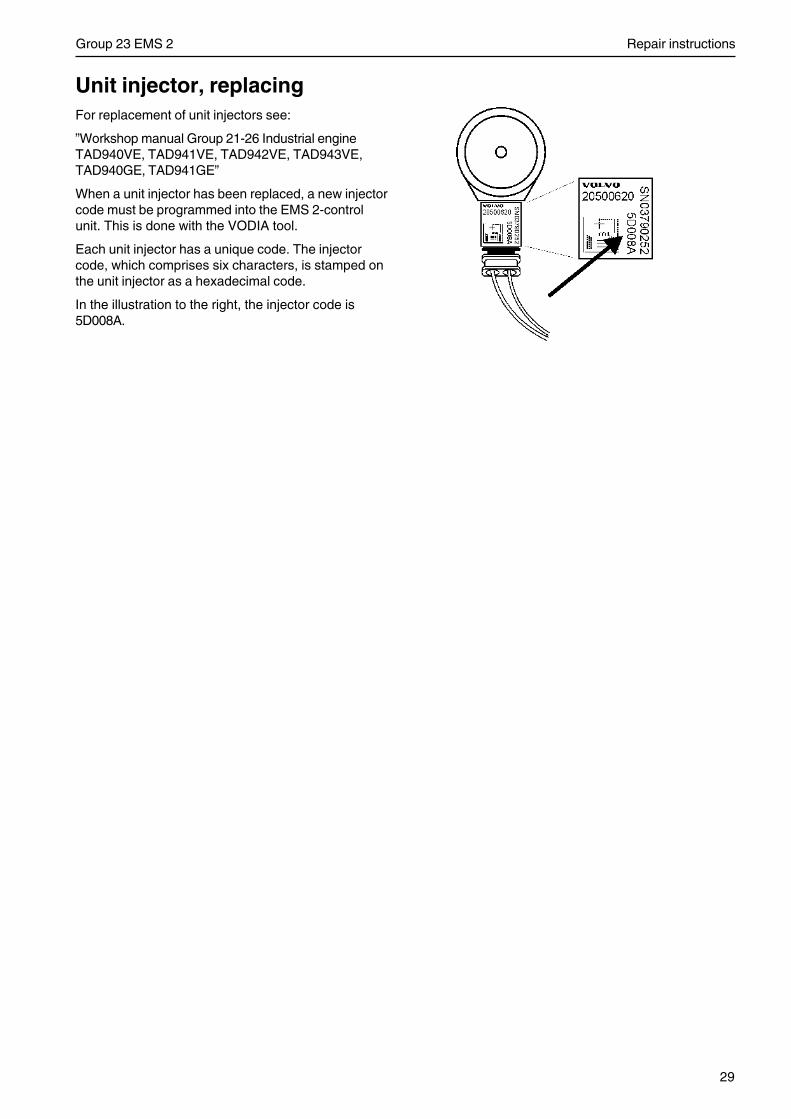
29
Group 23 EMS 2 Repair instructions
Unit injector, replacingFor replacement of unit injectors see:
”Workshop manual Group 21-26 Industrial engineTAD940VE, TAD941VE, TAD942VE, TAD943VE,TAD940GE, TAD941GE”
When a unit injector has been replaced, a new injectorcode must be programmed into the EMS 2-controlunit. This is done with the VODIA tool.
Each unit injector has a unique code. The injectorcode, which comprises six characters, is stamped onthe unit injector as a hexadecimal code.
In the illustration to the right, the injector code is5D008A.
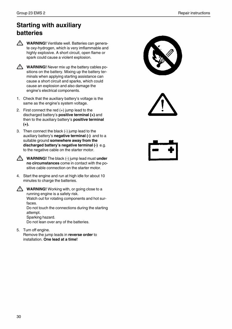
30
Group 23 EMS 2 Repair instructions
Starting with auxiliarybatteries
WARNING! Ventilate well. Batteries can genera-te oxy-hydrogen, which is very imflammable andhighly explosive. A short circuit, open flame orspark could cause a violent explosion.
WARNING! Never mix up the battery cables po-sitions on the battery. Mixing up the battery ter-minals when applying starting assistance cancause a short circuit and sparks, which couldcause an explosion and also damage theengine’s electrical components.
1. Check that the auxiliary battery’s voltage is thesame as the engine’s system voltage.
2. First connect the red (+) jump lead to thedischarged battery’s positive terminal (+) andthen to the auxiliary battery’s positive terminal(+).
3. Then connect the black (-) jump lead to theauxiliary battery’s negative terminal (-) and to asuitable ground somewhere away from thedischarged battery’s negative terminal (-) e.g.to the negative cable on the starter motor.
WARNING! The black (-) jump lead must underno circumstances come in contact with the po-sitive cable connection on the starter motor.
4. Start the engine and run at high idle for about 10minutes to charge the batteries.
WARNING! Working with, or going close to arunning engine is a safety risk.Watch out for rotating components and hot sur-faces.Do not touch the connections during the startingattempt.Sparking hazard.Do not lean over any of the batteries.
5. Turn off engine.Remove the jump leads in reverse order toinstallation. One lead at a time!
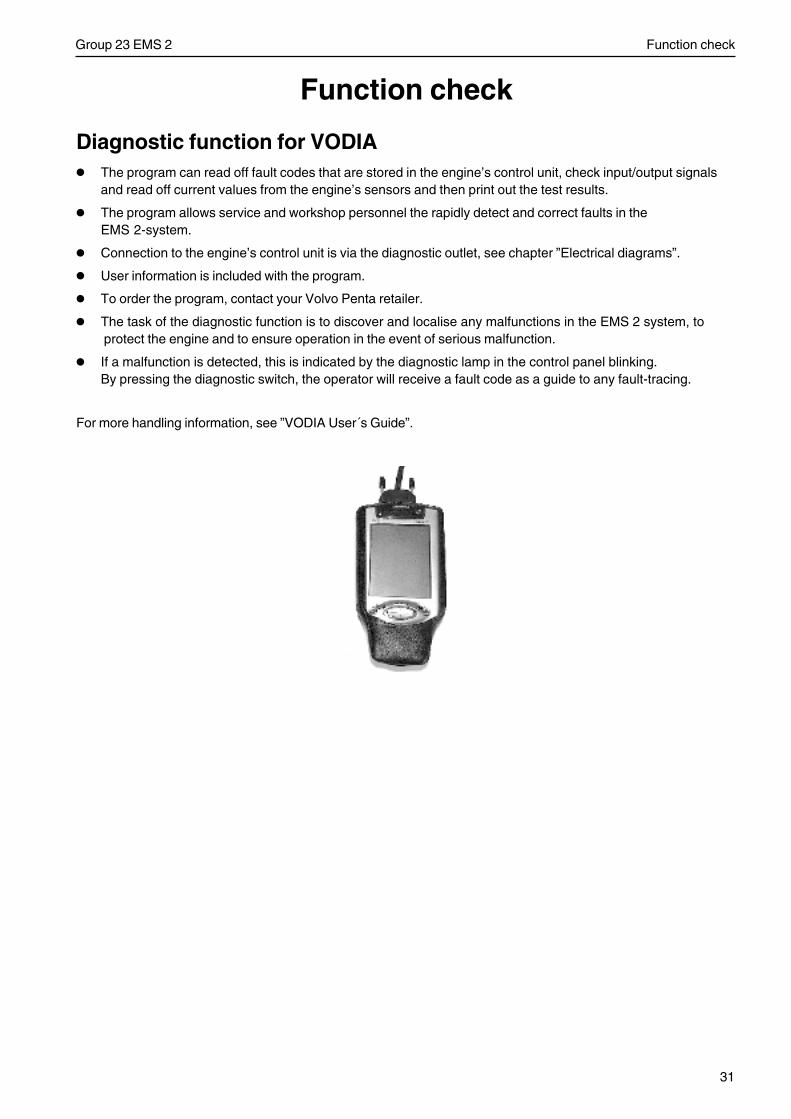
31
Group 23 EMS 2 Function check
Function check
Diagnostic function for VODIA
• The program can read off fault codes that are stored in the engine’s control unit, check input/output signalsand read off current values from the engine’s sensors and then print out the test results.
• The program allows service and workshop personnel the rapidly detect and correct faults in theEMS 2-system.
• Connection to the engine’s control unit is via the diagnostic outlet, see chapter ”Electrical diagrams”.
• User information is included with the program.
• To order the program, contact your Volvo Penta retailer.
• The task of the diagnostic function is to discover and localise any malfunctions in the EMS 2 system, to protect the engine and to ensure operation in the event of serious malfunction.
• If a malfunction is detected, this is indicated by the diagnostic lamp in the control panel blinking.By pressing the diagnostic switch, the operator will receive a fault code as a guide to any fault-tracing.
For more handling information, see ”VODIA User´s Guide”.
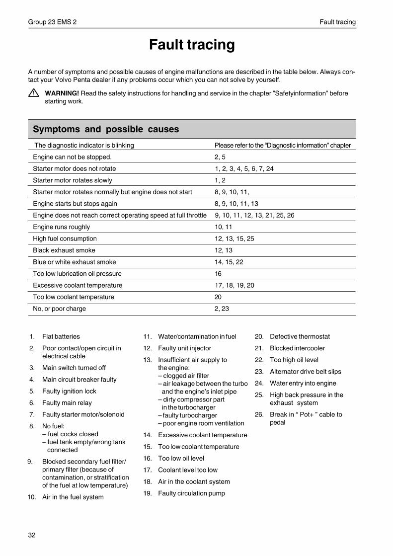
32
Group 23 EMS 2 Fault tracing
Fault tracing
A number of symptoms and possible causes of engine malfunctions are described in the table below. Always con-tact your Volvo Penta dealer if any problems occur which you can not solve by yourself.
WARNING! Read the safety instructions for handling and service in the chapter ”Safetyinformation” beforestarting work.
Symptoms and possible causes
The diagnostic indicator is blinking Please refer to the “Diagnostic information” chapter
Engine can not be stopped. 2, 5
Starter motor does not rotate 1, 2, 3, 4, 5, 6, 7, 24
Starter motor rotates slowly 1, 2
Starter motor rotates normally but engine does not start 8, 9, 10, 11,
Engine starts but stops again 8, 9, 10, 11, 13
Engine does not reach correct operating speed at full throttle 9, 10, 11, 12, 13, 21, 25, 26
Engine runs roughly 10, 11
High fuel consumption 12, 13, 15, 25
Black exhaust smoke 12, 13
Blue or white exhaust smoke 14, 15, 22
Too low lubrication oil pressure 16
Excessive coolant temperature 17, 18, 19, 20
Too low coolant temperature 20
No, or poor charge 2, 23
1. Flat batteries
2. Poor contact/open circuit inelectrical cable
3. Main switch turned off
4. Main circuit breaker faulty
5. Faulty ignition lock
6. Faulty main relay
7. Faulty starter motor/solenoid
8. No fuel:– fuel cocks closed– fuel tank empty/wrong tank
connected
9. Blocked secondary fuel filter/primary filter (because ofcontamination, or stratificationof the fuel at low temperature)
10. Air in the fuel system
11. Water/contamination in fuel
12. Faulty unit injector
13. Insufficient air supply tothe engine:– clogged air filter– air leakage between the turbo
and the engine’s inlet pipe– dirty compressor part
in the turbocharger– faulty turbocharger– poor engine room ventilation
14. Excessive coolant temperature
15. Too low coolant temperature
16. Too low oil level
17. Coolant level too low
18. Air in the coolant system
19. Faulty circulation pump
20. Defective thermostat
21. Blocked intercooler
22. Too high oil level
23. Alternator drive belt slips
24. Water entry into engine
25. High back pressure in theexhaust system
26. Break in “ Pot+ ” cable topedal
33
Group 23 EMS 2 Diagnostic function
Diagnostic function
Diagnostic functionThe diagnostic function monitors and checks that theEMS 2 system functions normally.
The diagnostic function has the following tasks:
• To detect and locate disturbances.
• To report that disturbances have been detected.
• To guide when troubleshooting.
Message regarding disturbanceIf the diagnosis function detects a disturbance inthe EMS 2 system this is reported by:
• the diagnostic lamp starts to flash
or
• information is shown in plain language on the in-strument panel
(depending on the equipment used).
All fault codes are found in the fault code list with in-formation about cause, reaction and actions. Seechapter on ”Fault codes”.
NOTE! The indicated flashing codes apply only if theVolvo Penta CIU is used.
Simultaneously, the fault will be stored in the controlmodule memory. As soon as the fault has been atten-ded to and the ignition is turned off and on, the faultcode lamp goes out. Both rectified (passive) and un-rectified (active) faults are stored in the control unitand can be read by an authorized workshop.
Effect on the engineThe engine is affected in different ways, depending onthe seriousness of the fault detected by the diagnosticfunction.
A fault message in the form of a fault code is alwaysgenerated when the diagnostic function discovers afault.
The engine is affected by different degrees (see be-low) depending on the seriousness of the fault:
• The engine is not affected.
• Engine goes to idle speed (VE engines).
• Engine torque is limited to different levels (VEengine)
• Engine is shut off.
OperationIf the system indicates that a fault code has been set:
1. Reduce engine speed to idling.
2. Press the diagnosis knob to acknowledge the message. Release the diagnostic button and make anote of the diagnostic trouble code (DTC) that isflashed out. See ”Reading fault codes”.
or
3. Read the fault code which is set directly on the in-strument panel.
4. Look up the fault code in the fault code list andtake the necessary measures.
NOTE! If the warning lamps and other instrumentationshow normal function while operating controls are wor-king normally, the operator can choose to continue theoperation and remedy the disturbance at a later time.If the engine is shut off, some fault codes may disap-pear.
34
Group 23 EMS 2 Diagnostic function
Reading fault codesFault codes can either be read via:
- Plain language on the instrument panel via theCAN link.
- Diagnosis lamp on instrument panel.
- For how to handle the VODIA-tool, see ”VODIAUser´s Guide”
If the diagnosis knob is depressed and then released,a fault code will flash.
The fault code consists of two groups of flashes, se-parated by a pause of two seconds. A fault code isobtained by counting the number of flashes in eachgroup.
Example: pause = Fault code 2.4
The fault code is stored and can be read as long asthe malfunction remains. You can find informationabout cause, reaction and actions in the fault codelist.
Read as follows:
1. Press the diagnostic button.
2. Release the diagnostic button and make a note ofthe fault that is flashed out.
3. Repeat items 1-2. A new fault code is flashed outif more are stored. Repeat until the first fault codeis repeated.
NOTE! When the first fault code returns, all fault co-des have been read.
Erasing fault codesThe diagnosis function fault code memory is set tozero when the voltage to the engine is disconnected.
NOTE! Voltage must be fully disconnected.
When voltage is turned on again, the diagnosis func-tion will check if there are any disturbances in theEMS 2 system. If this is the case, new fault codesare set.
This means that:
1. Fault codes for malfunctions that have beenrectified or disappeared are set as inactive (theinactive fault code can then be erased with theVODIA tool).
2. Fault codes for malfunctions which have not beenattended to must be acknowledged every time thesystem voltage is switched on.
If the diagnosis knob is depressed after the faultshave been corrected, and stored fault codes havebeen deleted, code 1.1 (”No fault”) will flash, seechapter on ”Fault codes”.
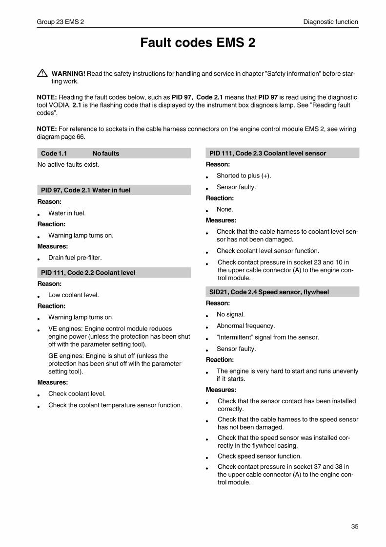
35
Group 23 EMS 2 Diagnostic function
WARNING! Read the safety instructions for handling and service in chapter ”Safety information” before star-ting work.
NOTE: Reading the fault codes below, such as PID 97, Code 2.1 means that PID 97 is read using the diagnostictool VODIA. 2.1 is the flashing code that is displayed by the instrument box diagnosis lamp. See ”Reading faultcodes”.
NOTE: For reference to sockets in the cable harness connectors on the engine control module EMS 2, see wiringdiagram page 66.
Fault codes EMS 2
PID 111, Code 2.3 Coolant level sensor
Reason:
• Shorted to plus (+).
• Sensor faulty.
Reaction:
• None.
Measures:
• Check that the cable harness to coolant level sen-sor has not been damaged.
• Check coolant level sensor function.
• Check contact pressure in socket 23 and 10 inthe upper cable connector (A) to the engine con-trol module.
SID21, Code 2.4 Speed sensor, flywheel
Reason:
• No signal.
• Abnormal frequency.
• ”Intermittent” signal from the sensor.
• Sensor faulty.
Reaction:
• The engine is very hard to start and runs unevenlyif it starts.
Measures:
• Check that the sensor contact has been installedcorrectly.
• Check that the cable harness to the speed sensorhas not been damaged.
• Check that the speed sensor was installed cor-rectly in the flywheel casing.
• Check speed sensor function.
• Check contact pressure in socket 37 and 38 inthe upper cable connector (A) to the engine con-trol module.
Code 1.1 No faults
No active faults exist.
PID 97, Code 2.1 Water in fuel
Reason:
• Water in fuel.
Reaction:
• Warning lamp turns on.
Measures:
• Drain fuel pre-filter.
PID 111, Code 2.2 Coolant level
Reason:
• Low coolant level.
Reaction:
• Warning lamp turns on.
• VE engines: Engine control module reducesengine power (unless the protection has been shutoff with the parameter setting tool).
GE engines: Engine is shut off (unless theprotection has been shut off with the parametersetting tool).
Measures:
• Check coolant level.
• Check the coolant temperature sensor function.
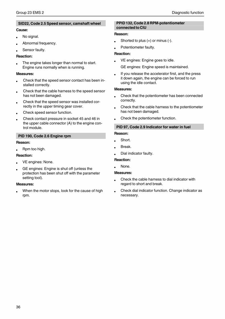
36
Group 23 EMS 2 Diagnostic function
SID22, Code 2.5 Speed sensor, camshaft wheel
Cause:
• No signal.
• Abnormal frequency.
• Sensor faulty.
Reaction:
• The engine takes longer than normal to start.Engine runs normally when is running.
Measures:
• Check that the speed sensor contact has been in-stalled correctly.
• Check that the cable harness to the speed sensorhas not been damaged.
• Check that the speed sensor was installed cor-rectly in the upper timing gear cover.
• Check speed sensor function.
• Check contact pressure in socket 45 and 46 inthe upper cable connector (A) to the engine con-trol module.
PID 190, Code 2.6 Engine rpm
Reason:
• Rpm too high.
Reaction:
• VE engines: None.
• GE engines: Engine is shut off (unless theprotection has been shut off with the parametersetting tool).
Measures:
• When the motor stops, look for the cause of highrpm.
PPID 132, Code 2.8 RPM-potentiometerconnected to CIU
Reason:
• Shorted to plus (+) or minus (-).
• Potentiometer faulty.
Reaction:
• VE engines: Engine goes to idle.
GE engines: Engine speed is maintained.
• If you release the accelerator first, and the pressit down again, the engine can be forced to runusing the idle contact.
Measures:
• Check that the potentiometer has been connectedcorrectly.
• Check that the cable harness to the potentiometerhas not been damaged.
• Check the potentiometer function.
PID 97, Code 2.9 Indicator for water in fuel
Reason:
• Short.
• Break.
• Dial indicator faulty.
Reaction:
• None.
Measures:
• Check the cable harness to dial indicator withregard to short and break.
• Check dial indicator function. Change indicator asnecessary.
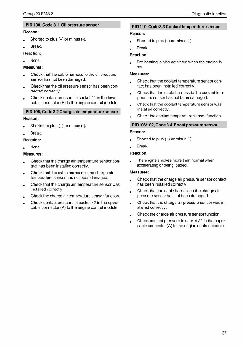
37
Group 23 EMS 2 Diagnostic function
PID 100, Code 3.1 Oil pressure sensor
Reason:
• Shorted to plus (+) or minus (-).
• Break.
Reaction:
• None.
Measures:
• Check that the cable harness to the oil pressuresensor has not been damaged.
• Check that the oil pressure sensor has been con-nected correctly.
• Check contact pressure in socket 11 in the lowercable connector (B) to the engine control module.
PID 105, Code 3.2 Charge air temperature sensor
Reason:
• Shorted to plus (+) or minus (-).
• Break.
Reaction:
• None.
Measures:
• Check that the charge air temperature sensor con-tact has been installed correctly.
• Check that the cable harness to the charge airtemperature sensor has not been damaged.
• Check that the charge air temperature sensor wasinstalled correctly.
• Check the charge air temperature sensor function.
• Check contact pressure in socket 47 in the uppercable connector (A) to the engine control module.
PID 110, Code 3.3 Coolant temperature sensor
Reason:
• Shorted to plus (+) or minus (-).
• Break.
Reaction:
• Pre-heating is also activated when the engine ishot.
Measures:
• Check that the coolant temperature sensor con-tact has been installed correctly.
• Check that the cable harness to the coolant tem-perature sensor has not been damaged.
• Check that the coolant temperature sensor wasinstalled correctly.
• Check the coolant temperature sensor function.
PID106/102, Code 3.4 Boost pressure sensor
Reason:
• Shorted to plus (+) or minus (-).
• Break.
Reaction:
• The engine smokes more than normal whenaccelerating or being loaded.
Measures:
• Check that the charge air pressure sensor contacthas been installed correctly.
• Check that the cable harness to the charge airpressure sensor has not been damaged.
• Check that the charge air pressure sensor was in-stalled correctly.
• Check the charge air pressure sensor function.
• Check contact pressure in socket 22 in the uppercable connector (A) to the engine control module.
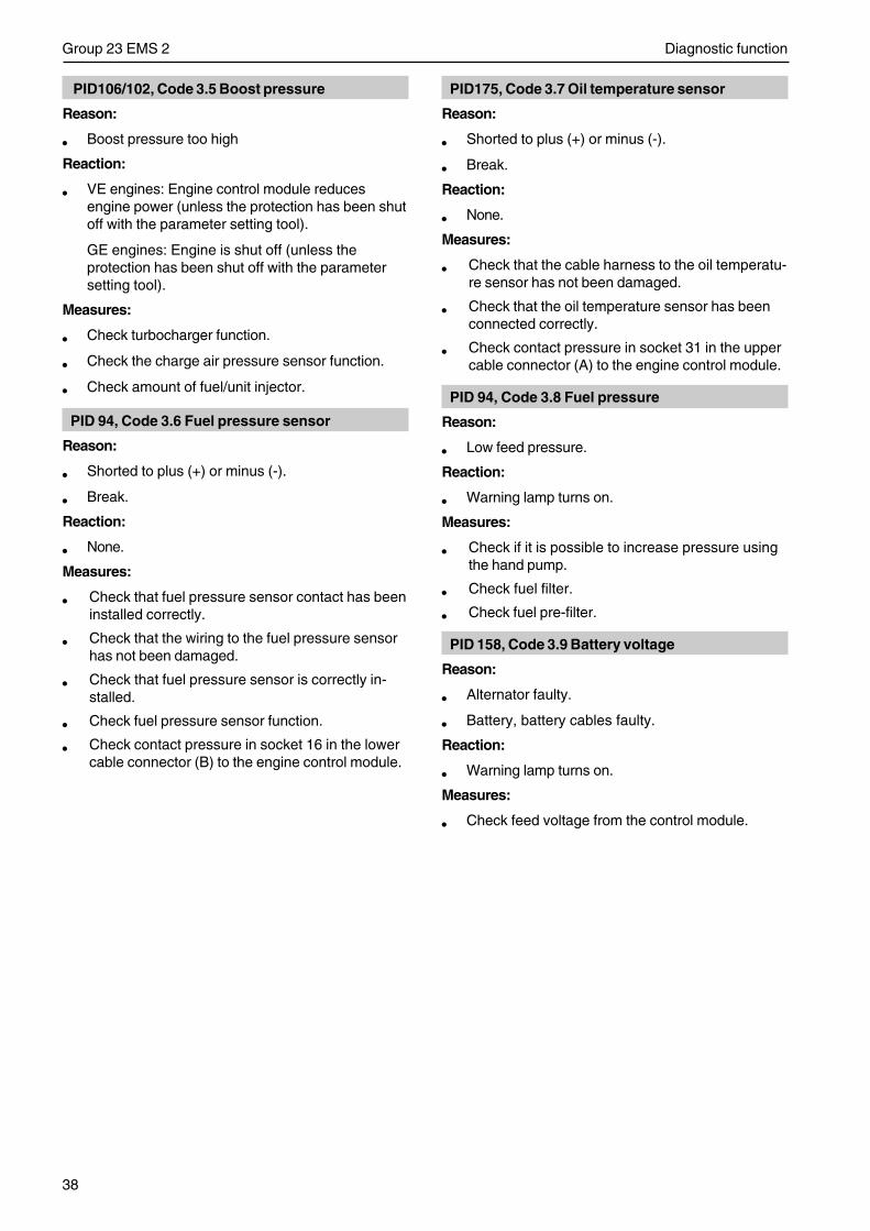
38
Group 23 EMS 2 Diagnostic function
PID106/102, Code 3.5 Boost pressure
Reason:
• Boost pressure too high
Reaction:
• VE engines: Engine control module reducesengine power (unless the protection has been shutoff with the parameter setting tool).
GE engines: Engine is shut off (unless theprotection has been shut off with the parametersetting tool).
Measures:
• Check turbocharger function.
• Check the charge air pressure sensor function.
• Check amount of fuel/unit injector.
PID 94, Code 3.6 Fuel pressure sensor
Reason:
• Shorted to plus (+) or minus (-).
• Break.
Reaction:
• None.
Measures:
• Check that fuel pressure sensor contact has beeninstalled correctly.
• Check that the wiring to the fuel pressure sensorhas not been damaged.
• Check that fuel pressure sensor is correctly in-stalled.
• Check fuel pressure sensor function.
• Check contact pressure in socket 16 in the lowercable connector (B) to the engine control module.
PID175, Code 3.7 Oil temperature sensor
Reason:
• Shorted to plus (+) or minus (-).
• Break.
Reaction:
• None.
Measures:
• Check that the cable harness to the oil temperatu-re sensor has not been damaged.
• Check that the oil temperature sensor has beenconnected correctly.
• Check contact pressure in socket 31 in the uppercable connector (A) to the engine control module.
PID 94, Code 3.8 Fuel pressure
Reason:
• Low feed pressure.
Reaction:
• Warning lamp turns on.
Measures:
• Check if it is possible to increase pressure usingthe hand pump.
• Check fuel filter.
• Check fuel pre-filter.
PID 158, Code 3.9 Battery voltage
Reason:
• Alternator faulty.
• Battery, battery cables faulty.
Reaction:
• Warning lamp turns on.
Measures:
• Check feed voltage from the control module.
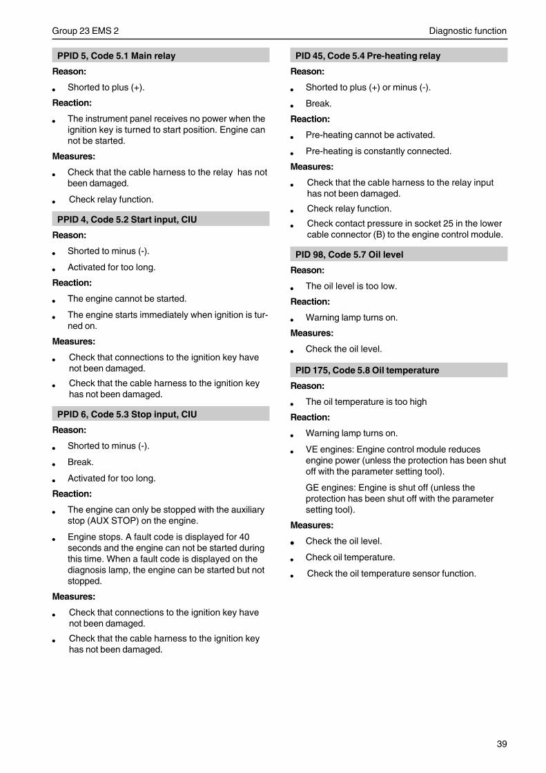
39
Group 23 EMS 2 Diagnostic function
PPID 5, Code 5.1 Main relay
Reason:
• Shorted to plus (+).
Reaction:
• The instrument panel receives no power when theignition key is turned to start position. Engine cannot be started.
Measures:
• Check that the cable harness to the relay has notbeen damaged.
• Check relay function.
PPID 4, Code 5.2 Start input, CIU
Reason:
• Shorted to minus (-).
• Activated for too long.
Reaction:
• The engine cannot be started.
• The engine starts immediately when ignition is tur-ned on.
Measures:
• Check that connections to the ignition key havenot been damaged.
• Check that the cable harness to the ignition keyhas not been damaged.
PPID 6, Code 5.3 Stop input, CIU
Reason:
• Shorted to minus (-).
• Break.
• Activated for too long.
Reaction:
• The engine can only be stopped with the auxiliarystop (AUX STOP) on the engine.
• Engine stops. A fault code is displayed for 40seconds and the engine can not be started duringthis time. When a fault code is displayed on thediagnosis lamp, the engine can be started but notstopped.
Measures:
• Check that connections to the ignition key havenot been damaged.
• Check that the cable harness to the ignition keyhas not been damaged.
PID 45, Code 5.4 Pre-heating relay
Reason:
• Shorted to plus (+) or minus (-).
• Break.
Reaction:
• Pre-heating cannot be activated.
• Pre-heating is constantly connected.
Measures:
• Check that the cable harness to the relay inputhas not been damaged.
• Check relay function.
• Check contact pressure in socket 25 in the lowercable connector (B) to the engine control module.
PID 98, Code 5.7 Oil level
Reason:
• The oil level is too low.
Reaction:
• Warning lamp turns on.
Measures:
• Check the oil level.
PID 175, Code 5.8 Oil temperature
Reason:
• The oil temperature is too high
Reaction:
• Warning lamp turns on.
• VE engines: Engine control module reducesengine power (unless the protection has been shutoff with the parameter setting tool).
GE engines: Engine is shut off (unless theprotection has been shut off with the parametersetting tool).
Measures:
• Check the oil level.
• Check oil temperature.
• Check the oil temperature sensor function.
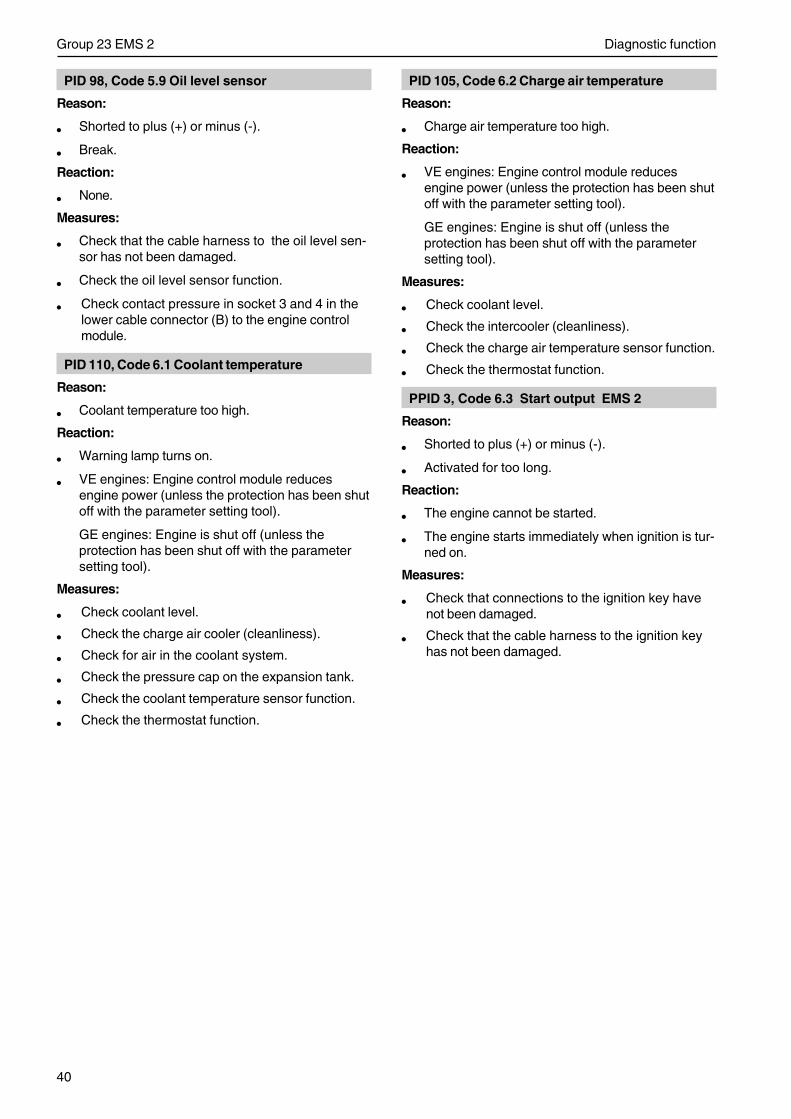
40
Group 23 EMS 2 Diagnostic function
PID 98, Code 5.9 Oil level sensor
Reason:
• Shorted to plus (+) or minus (-).
• Break.
Reaction:
• None.
Measures:
• Check that the cable harness to the oil level sen-sor has not been damaged.
• Check the oil level sensor function.
• Check contact pressure in socket 3 and 4 in thelower cable connector (B) to the engine controlmodule.
PID 110, Code 6.1 Coolant temperature
Reason:
• Coolant temperature too high.
Reaction:
• Warning lamp turns on.
• VE engines: Engine control module reducesengine power (unless the protection has been shutoff with the parameter setting tool).
GE engines: Engine is shut off (unless theprotection has been shut off with the parametersetting tool).
Measures:
• Check coolant level.
• Check the charge air cooler (cleanliness).
• Check for air in the coolant system.
• Check the pressure cap on the expansion tank.
• Check the coolant temperature sensor function.
• Check the thermostat function.
PID 105, Code 6.2 Charge air temperature
Reason:
• Charge air temperature too high.
Reaction:
• VE engines: Engine control module reducesengine power (unless the protection has been shutoff with the parameter setting tool).
GE engines: Engine is shut off (unless theprotection has been shut off with the parametersetting tool).
Measures:
• Check coolant level.
• Check the intercooler (cleanliness).
• Check the charge air temperature sensor function.
• Check the thermostat function.
PPID 3, Code 6.3 Start output EMS 2
Reason:
• Shorted to plus (+) or minus (-).
• Activated for too long.
Reaction:
• The engine cannot be started.
• The engine starts immediately when ignition is tur-ned on.
Measures:
• Check that connections to the ignition key havenot been damaged.
• Check that the cable harness to the ignition keyhas not been damaged.
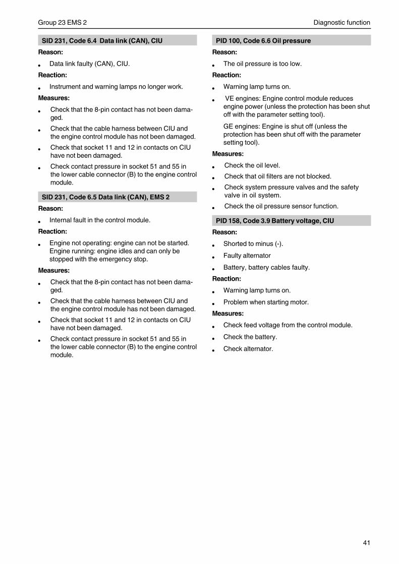
41
Group 23 EMS 2 Diagnostic function
SID 231, Code 6.4 Data link (CAN), CIU
Reason:
• Data link faulty (CAN), CIU.
Reaction:
• Instrument and warning lamps no longer work.
Measures:
• Check that the 8-pin contact has not been dama-ged.
• Check that the cable harness between CIU andthe engine control module has not been damaged.
• Check that socket 11 and 12 in contacts on CIUhave not been damaged.
• Check contact pressure in socket 51 and 55 inthe lower cable connector (B) to the engine controlmodule.
SID 231, Code 6.5 Data link (CAN), EMS 2
Reason:
• Internal fault in the control module.
Reaction:
• Engine not operating: engine can not be started.Engine running: engine idles and can only bestopped with the emergency stop.
Measures:
• Check that the 8-pin contact has not been dama-ged.
• Check that the cable harness between CIU andthe engine control module has not been damaged.
• Check that socket 11 and 12 in contacts on CIUhave not been damaged.
• Check contact pressure in socket 51 and 55 inthe lower cable connector (B) to the engine controlmodule.
PID 100, Code 6.6 Oil pressure
Reason:
• The oil pressure is too low.
Reaction:
• Warning lamp turns on.
• VE engines: Engine control module reducesengine power (unless the protection has been shutoff with the parameter setting tool).
GE engines: Engine is shut off (unless theprotection has been shut off with the parametersetting tool).
Measures:
• Check the oil level.
• Check that oil filters are not blocked.
• Check system pressure valves and the safetyvalve in oil system.
• Check the oil pressure sensor function.
PID 158, Code 3.9 Battery voltage, CIU
Reason:
• Shorted to minus (-).
• Faulty alternator
• Battery, battery cables faulty.
Reaction:
• Warning lamp turns on.
• Problem when starting motor.
Measures:
• Check feed voltage from the control module.
• Check the battery.
• Check alternator.
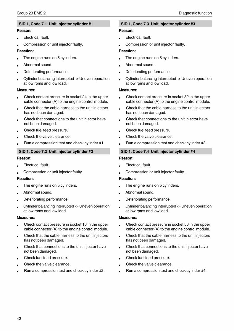
42
Group 23 EMS 2 Diagnostic function
SID 1, Code 7.1 Unit injector cylinder #1
Reason:
• Electrical fault.
• Compression or unit injector faulty.
Reaction:
• The engine runs on 5 cylinders.
• Abnormal sound.
• Deteriorating performance.
• Cylinder balancing interrupted -> Uneven operationat low rpms and low load.
Measures:
• Check contact pressure in socket 24 in the uppercable connector (A) to the engine control module.
• Check that the cable harness to the unit injectorshas not been damaged.
• Check that connections to the unit injector havenot been damaged.
• Check fuel feed pressure.
• Check the valve clearance.
• Run a compression test and check cylinder #1.
SID 1, Code 7.2 Unit injector cylinder #2
Reason:
• Electrical fault.
• Compression or unit injector faulty.
Reaction:
• The engine runs on 5 cylinders.
• Abnormal sound.
• Deteriorating performance.
• Cylinder balancing interrupted -> Uneven operationat low rpms and low load.
Measures:
• Check contact pressure in socket 16 in the uppercable connector (A) to the engine control module.
• Check that the cable harness to the unit injectorshas not been damaged.
• Check that connections to the unit injector havenot been damaged.
• Check fuel feed pressure.
• Check the valve clearance.
• Run a compression test and check cylinder #2.
SID 1, Code 7.3 Unit injector cylinder #3
Reason:
• Electrical fault.
• Compression or unit injector faulty.
Reaction:
• The engine runs on 5 cylinders.
• Abnormal sound.
• Deteriorating performance.
• Cylinder balancing interrupted -> Uneven operationat low rpms and low load.
Measures:
• Check contact pressure in socket 32 in the uppercable connector (A) to the engine control module.
• Check that the cable harness to the unit injectorshas not been damaged.
• Check that connections to the unit injector havenot been damaged.
• Check fuel feed pressure.
• Check the valve clearance.
• Run a compression test and check cylinder #3.
SID 1, Code 7.4 Unit injector cylinder #4
Reason:
• Electrical fault.
• Compression or unit injector faulty.
Reaction:
• The engine runs on 5 cylinders.
• Abnormal sound.
• Deteriorating performance.
• Cylinder balancing interrupted -> Uneven operationat low rpms and low load.
Measures:
• Check contact pressure in socket 56 in the uppercable connector (A) to the engine control module.
• Check that the cable harness to the unit injectorshas not been damaged.
• Check that connections to the unit injector havenot been damaged.
• Check fuel feed pressure.
• Check the valve clearance.
• Run a compression test and check cylinder #4.
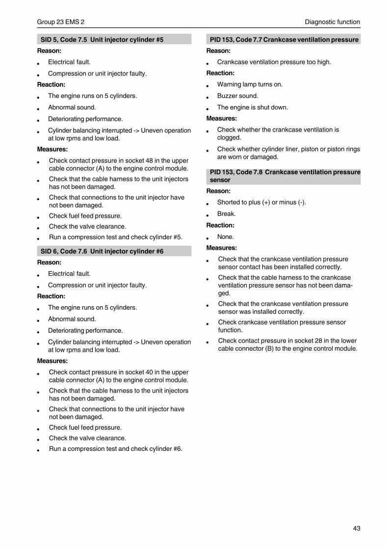
43
Group 23 EMS 2 Diagnostic function
SID 5, Code 7.5 Unit injector cylinder #5
Reason:
• Electrical fault.
• Compression or unit injector faulty.
Reaction:
• The engine runs on 5 cylinders.
• Abnormal sound.
• Deteriorating performance.
• Cylinder balancing interrupted -> Uneven operationat low rpms and low load.
Measures:
• Check contact pressure in socket 48 in the uppercable connector (A) to the engine control module.
• Check that the cable harness to the unit injectorshas not been damaged.
• Check that connections to the unit injector havenot been damaged.
• Check fuel feed pressure.
• Check the valve clearance.
• Run a compression test and check cylinder #5.
SID 6, Code 7.6 Unit injector cylinder #6
Reason:
• Electrical fault.
• Compression or unit injector faulty.
Reaction:
• The engine runs on 5 cylinders.
• Abnormal sound.
• Deteriorating performance.
• Cylinder balancing interrupted -> Uneven operationat low rpms and low load.
Measures:
• Check contact pressure in socket 40 in the uppercable connector (A) to the engine control module.
• Check that the cable harness to the unit injectorshas not been damaged.
• Check that connections to the unit injector havenot been damaged.
• Check fuel feed pressure.
• Check the valve clearance.
• Run a compression test and check cylinder #6.
PID 153, Code 7.7 Crankcase ventilation pressure
Reason:
• Crankcase ventilation pressure too high.
Reaction:
• Warning lamp turns on.
• Buzzer sound.
• The engine is shut down.
Measures:
• Check whether the crankcase ventilation isclogged.
• Check whether cylinder liner, piston or piston ringsare worn or damaged.
PID 153, Code 7.8 Crankcase ventilation pressuresensor
Reason:
• Shorted to plus (+) or minus (-).
• Break.
Reaction:
• None.
Measures:
• Check that the crankcase ventilation pressuresensor contact has been installed correctly.
• Check that the cable harness to the crankcaseventilation pressure sensor has not been dama-ged.
• Check that the crankcase ventilation pressuresensor was installed correctly.
• Check crankcase ventilation pressure sensorfunction.
• Check contact pressure in socket 28 in the lowercable connector (B) to the engine control module.
44
Group 23 EMS 2 Diagnostic function
SID250, Code 9.2 Data link faulty (J1708/J1587)
Reason:
• Data link faulty.
Reaction:
• Warning lamp turns on.
Measures:
• Check that the 8-pin contact has not been dama-ged.
• Check that the cable harness between CIU andthe engine control module has not been damaged.
• Check that socket 22 and 37 in contacts on CIUhave not been damaged.
• Check contact pressure in socket 33 and 34 inthe upper cable connector (A) to the engine con-trol module.
SID232, Code 9.3 Voltage feed to sensor
Reason:
• Short.
• Fault in oil pressure and/or charge air pressuresensor.
Reaction:
• Incorrect values from oil pressure- and charge airpressure sensor.
• Fault code for oil pressure- and charge airpressure sensor.
• Low engine output.
• The instrument shows zero oil pressure and boostpressure.
Measures:
• Check that the cable harness to oil pressure- andcharge air pressure sensor has not beendamaged.
• Check contact pressure in socket 7 in the uppercable connector (A) to the engine control module.
• Check oil pressure and charge air pressuresensors.
SID 254, Code 9.8 Control module fault, CIU
Reason:
• EEPROM, CIU, faulty
• Flash memory, CIU faulty.
• Fault in control module, CIU
Reaction:
• CIU reverts to factory settings.
• The engine runs at idle.
• Engine cannot be started.
Measures:
• Replace CIU-unit.
SID 240, Code 9.9 Memory fault in EMS 2
Reason:
• Engine control module memory fault.
Reaction:
• Engine may not start.
Measures:
• Replace the engine control module.
SID 253, Code 9.9 Data set memory EEPROM
Reason:
• Internal fault in the control module
• Programming faulty.
Reaction:
• Engine does not start.
Measures:
• Re-program the control module. If the faultremains, change the control module.
SID 254, Code 9.9 Control module EMS 2
Reason:
• Internal fault in the control module.
Reaction:
• Engine misfires.
• Engine does not start.
Measures:
• Replace the engine control module.
45
Group 23 EMS 2 Electrical fault tracing
Electrical fault tracing
GeneralBefore performing electrical fault tracing, the followingshould be checked:
• Fault codes
• Fuel level and fuel filter
• Air filter
• Battery
• Wiring (visual)
• Main switch, fuses, connectors
• Relay connections
Functional check of wiring andconnector blocks
Connection problemsLoose connectors or occasionally recurring faults canbe difficult to fault trace and often occur due to oxida-tion, vibration or poorly connected leads.
Wear can be another reason for faults. Therefore avoiddisconnecting connector blocks if it is not necessary.
Other connector problems can arise due to pins, sock-ets and connector blocks being damaged.
Shake the lead and pull on the connector while mea-suring to help find damaged wiring.
The resistance in connectors, wiring and connectionsshould be 0 Ohm.A certain resistance is always present however, dueto oxidation of connections.
If this resistance increases too much, it can lead tomalfunctions. The size of the resistance before itstarts causing malfunctions varies depending on howlarge a load the circuit is carrying.
Check the following:
• Look for oxidation that can worsen connector con-tact in the connections.
• Check that the connector pins/sockets are unda-maged, that they are properly inserted in the con-nector blocks and that the wires are properly con-nected to the pins.
• Test the connector blocks for good mechanicalcontact. Use a loose pin for the test.
Important! The control unit’s (EMS 2) cableconnector must only be checked with gauge9998482.
• Push gauge 9998482 carefully into the connectorsockets. Pull/push the gauge back and forth se-veral times, check that the socket grips aroundthe gauge. If the connector socket has insufficientgripping power, the socket must be replaced. See”Splicing cables for cable connectors”.
• Fill connector sockets that have been checkedwith low temperature grease 1161417-9.
Important! DIN connectors for the pressuresensor must not be filled with grease.
• Check that the wires are properly crimped. Avoidshort crimps on wires to the connector pins/sockets.
46
Group 23 EMS 2 Electrical fault tracing
Functional check of wiring andconnector blocks
Check connections visuallyCheck the following:
• Look for oxidation that can worsen connector con-tact in the connections.
• Check that the connector pins/sockets are unda-maged, that they are properly inserted in the con-nector blocks and that the wires are properly con-nected to the pins.
• Test the connector blocks for good mechanicalcontact. Use a loose pin for the test.
• Shake the lead and pull on the connector whilemeasuring to help find damaged wiring.
Open circuitChafed or torn wiring as well as loose contacts can bepossible fault causes.
Check, using the wiring diagram, which cable harnessis used by the function. Start with the most likely ca-ble harness in the circuit.
Check the following:
• Disconnect the connector blocks at both ends ofthe cable harness.
• Measure the resistance with multimeter 9510060between the ends of the cable. Expected value~ 0 Ω.
• Shake the lead and pull on the connector whilemeasuring to help find damaged wiring.
• If the fault cannot be found, check the next cableharness according to the wiring diagram..
Connector resistance and oxidation.The resistance in connectors, wiring and connectionsshould be 0 Ω.A certain resistance is always present however, dueto oxidation of connections.
If this resistance increases too much, it can lead tomalfunctions. The size of the resistance before itstarts causing malfunctions varies depending on howlarge a load the circuit is carrying.
Check the following:
• Look for oxidation that can worsen connector con-tact in the connections.
• Check that the connector pins/sockets are unda-maged, that they are properly inserted in the con-nector blocks and that the wires are properly con-nected to the pins.
• Test the connector blocks for good mechanicalcontact. Use a loose pin for the test.
Important! DIN connectors for the pressuresensor must not be filled with grease.
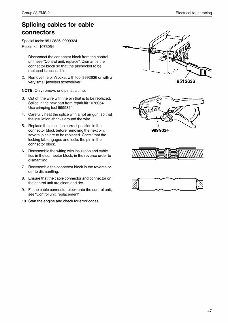
47
Group 23 EMS 2 Electrical fault tracing
Splicing cables for cableconnectorsSpecial tools: 951 2636, 9999324
Repair kit: 1078054
1. Disconnect the connector block from the controlunit, see ”Control unit, replace”. Dismantle theconnector block so that the pin/socket to bereplaced is accessible.
2. Remove the pin/socket with tool 9992636 or with avery small jewelers screwdriver.
NOTE: Only remove one pin at a time.
3. Cut off the wire with the pin that is to be replaced.Splice in the new part from repair kit 1078054.Use crimping tool 9999324.
4. Carefully heat the splice with a hot air gun, so thatthe insulation shrinks around the wire.
5. Replace the pin in the correct position in theconnector block before removing the next pin, ifseveral pins are to be replaced. Check that thelocking tab engages and locks the pin in theconnector block.
6. Reassemble the wiring with insulation and cableties in the connector block, in the reverse order todismantling.
7. Reassemble the connector block in the reverse or-der to dismantling.
8. Ensure that the cable connector and connector onthe control unit are clean and dry.
9. Fit the cable connector block onto the control unit,see “Control unit, replacement”.
10. Start the engine and check for error codes.
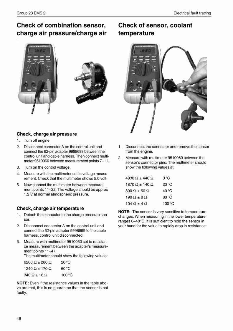
48
Group 23 EMS 2 Electrical fault tracing
Check of sensor, coolanttemperature
1. Disconnect the connector and remove the sensorfrom the engine.
2. Measure with multimeter 9510060 between thesensor’s connector pins. The multimeter shouldshow the following values at:
4930 Ω ± 440 Ω 0 °C
1870 Ω ± 140 Ω 20 °C
800 Ω ± 50 Ω 40 °C
190 Ω ± 8 Ω 80 °C
104 Ω ± 4 Ω 100 °C
NOTE: The sensor is very sensitive to temperaturechanges. When measuring in the lower temperatureranges 0–40°C, it is sufficient to hold the sensor inyour hand for the value to rapidly drop in resistance.
Check of combination sensor,charge air pressure/charge airtemperature
Check, charge air pressure1. Turn off engine
2. Disconnect connector A on the control unit andconnect the 62-pin adapter 9998699 between thecontrol unit and cable harness. Then connect multi-meter 9510060 between measurement points 7–11.
3. Turn on the control voltage.
4. Measure with the multimeter set to voltage measu-rement. Check that the multimeter shows 5.0 volt.
5. Now connect the multimeter between measure-ment points 11–22. The voltage should be approx1.2 V at normal atmospheric pressure.
Check, charge air temperature1. Detach the connector to the charge pressure sen-
sor.
2. Disconnect connector A on the control unit andconnect the 62-pin adapter 9998699 to the cableharness, control unit disconnected.
3. Measure with multimeter 9510060 set to resistan-ce measurement between the adapter’s measure-ment points 11–47.The multimeter should show the following values:
6200 Ω ± 280 Ω 20 °C
1240 Ω ± 170 Ω 60 °C
340 Ω ± 16 Ω 100 °C
NOTE: Even if the resistance values in the table abo-ve are met, this is no guarantee that the sensor is notfaulty.
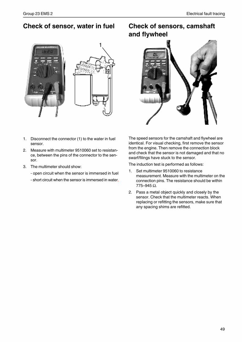
49
Group 23 EMS 2 Electrical fault tracing
Check of sensor, water in fuel
1. Disconnect the connector (1) to the water in fuelsensor.
2. Measure with multimeter 9510060 set to resistan-ce, between the pins of the connector to the sen-sor.
3. The multimeter should show:
- open circuit when the sensor is immersed in fuel
- short circuit when the sensor is immersed in water.
Check of sensors, camshaftand flywheel
The speed sensors for the camshaft and flywheel areidentical. For visual checking, first remove the sensorfrom the engine. Then remove the connection blockand check that the sensor is not damaged and that noswarf/filings have stuck to the sensor.
The induction test is performed as follows:
1. Set multimeter 9510060 to resistancemeasurement. Measure with the multimeter on theconnection pins. The resistance should be within775–945 Ω.
2. Pass a metal object quickly and closely by thesensor. Check that the multimeter reacts. Whenreplacing or refitting the sensors, make sure thatany spacing shims are refitted.
1
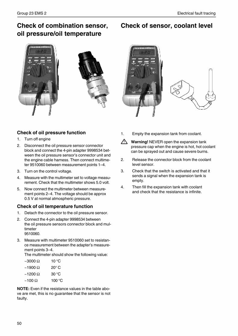
50
Group 23 EMS 2 Electrical fault tracing
Check of sensor, coolant level
1. Empty the expansion tank from coolant.
Warning! NEVER open the expansion tankpressure cap when the engine is hot, hot coolantcan be sprayed out and cause severe burns.
2. Release the connector block from the coolantlevel sensor.
3. Check that the switch is activated and that itsends a signal when the expansion tank isempty.
4. Then fill the expansion tank with coolantand check that the resistance is infinite.
Check of combination sensor,oil pressure/oil temperature
Check of oil pressure function1. Turn off engine
2. Disconnect the oil pressure sensor connectorblock and connect the 4-pin adapter 9998534 bet-ween the oil pressure sensor’s connector unit andthe engine cable harness. Then connect multime-ter 9510060 between measurement points 1–4.
3. Turn on the control voltage.
4. Measure with the multimeter set to voltage measu-rement. Check that the multimeter shows 5.0 volt.
5. Now connect the multimeter between measure-ment points 2–4. The voltage should be approx0.5 V at normal atmospheric pressure.
Check of oil temperature function1. Detach the connector to the oil pressure sensor.
2. Connect the 4-pin adapter 9998534 betweenthe oil pressure sensors connector block and mul-timeter9510060.
3. Measure with multimeter 9510060 set to resistan-ce measurement between the adapter’s measure-ment points 3–4.The multimeter should show the following value:
~3000 Ω 10 °C
~1900 Ω 20° C
~1200 Ω 30 °C
~100 Ω 100 °C
NOTE: Even if the resistance values in the table abo-ve are met, this is no guarantee that the sensor is notfaulty.
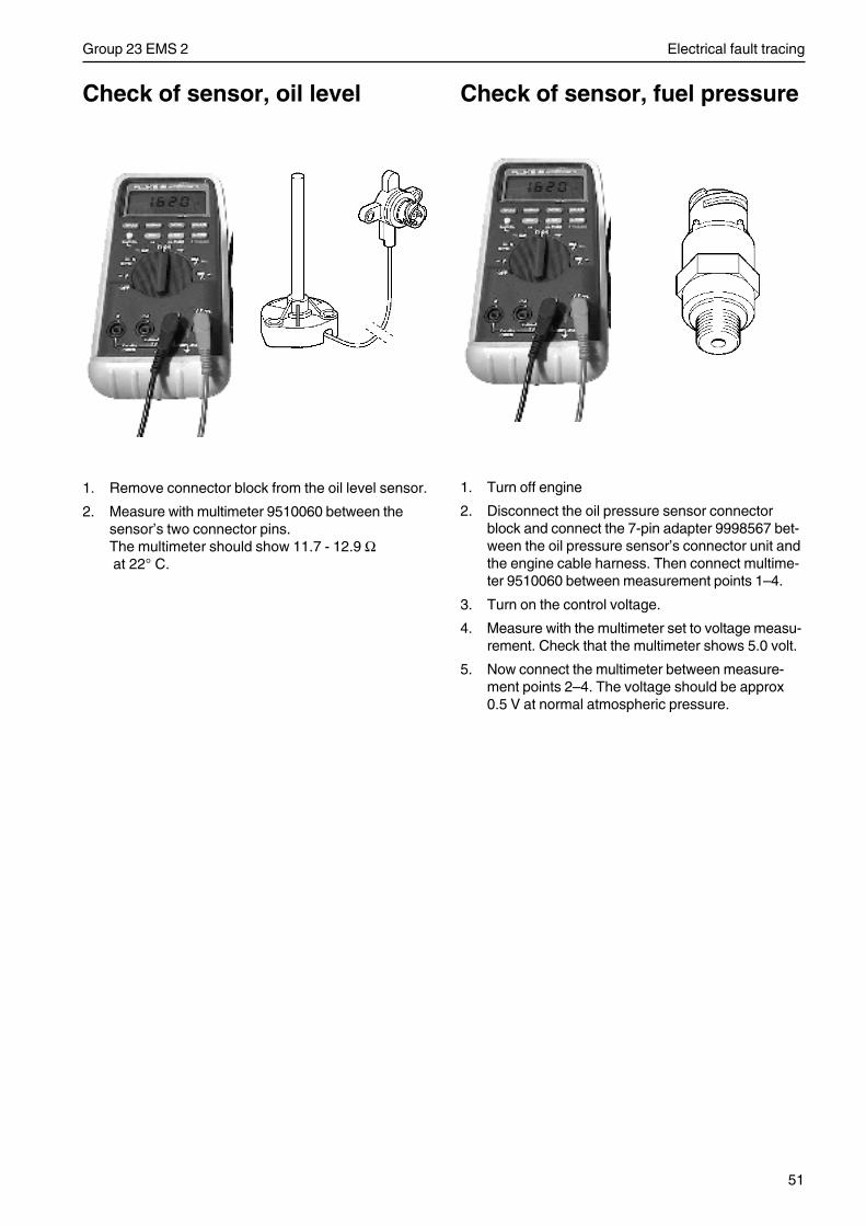
51
Group 23 EMS 2 Electrical fault tracing
Check of sensor, oil level
1. Remove connector block from the oil level sensor.
2. Measure with multimeter 9510060 between thesensor’s two connector pins.The multimeter should show 11.7 - 12.9 Ω at 22° C.
Check of sensor, fuel pressure
1. Turn off engine
2. Disconnect the oil pressure sensor connectorblock and connect the 7-pin adapter 9998567 bet-ween the oil pressure sensor’s connector unit andthe engine cable harness. Then connect multime-ter 9510060 between measurement points 1–4.
3. Turn on the control voltage.
4. Measure with the multimeter set to voltage measu-rement. Check that the multimeter shows 5.0 volt.
5. Now connect the multimeter between measure-ment points 2–4. The voltage should be approx0.5 V at normal atmospheric pressure.
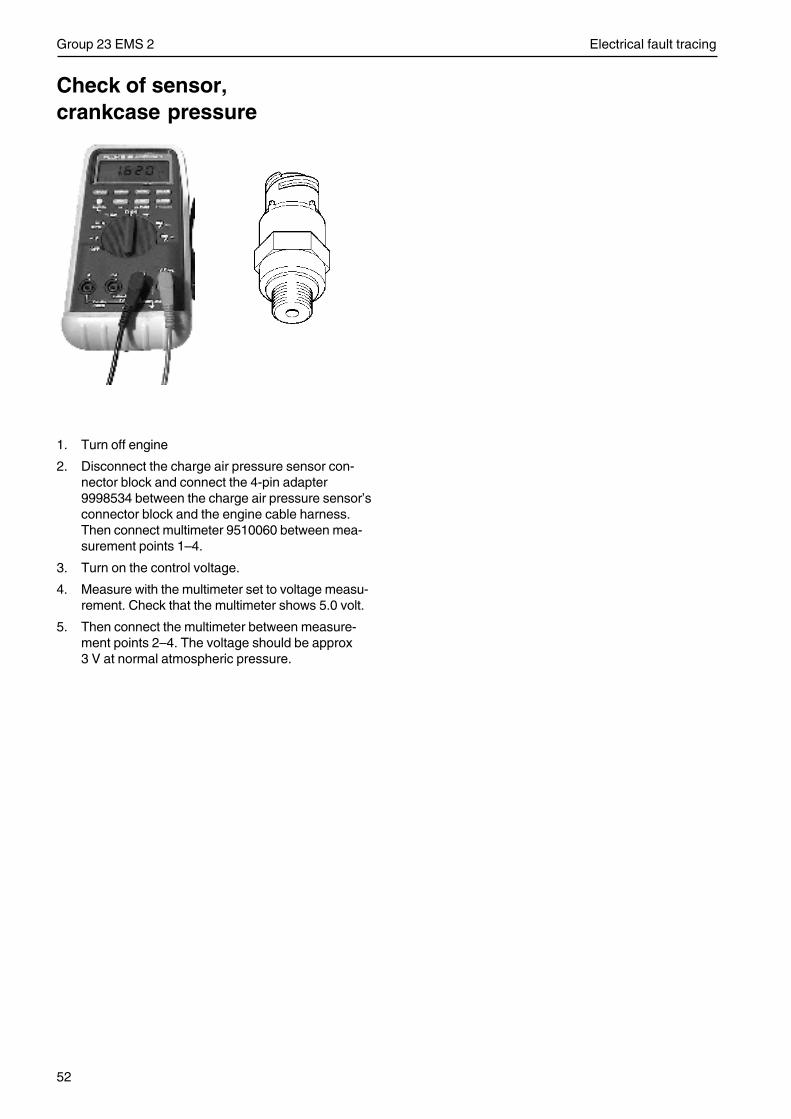
52
Group 23 EMS 2 Electrical fault tracing
Check of sensor,crankcase pressure
1. Turn off engine
2. Disconnect the charge air pressure sensor con-nector block and connect the 4-pin adapter9998534 between the charge air pressure sensor’sconnector block and the engine cable harness.Then connect multimeter 9510060 between mea-surement points 1–4.
3. Turn on the control voltage.
4. Measure with the multimeter set to voltage measu-rement. Check that the multimeter shows 5.0 volt.
5. Then connect the multimeter between measure-ment points 2–4. The voltage should be approx3 V at normal atmospheric pressure.
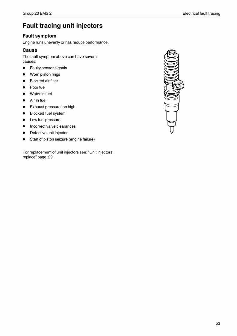
53
Group 23 EMS 2 Electrical fault tracing
Fault tracing unit injectors
Fault symptomEngine runs unevenly or has reduce performance.
CauseThe fault symptom above can have severalcauses:
• Faulty sensor signals
• Worn piston rings
• Blocked air filter
• Poor fuel
• Water in fuel
• Air in fuel
• Exhaust pressure too high
• Blocked fuel system
• Low fuel pressure
• Incorrect valve clearances
• Defective unit injector
• Start of piston seizure (engine failure)
For replacement of unit injectors see: ”Unit injectors,replace” page. 29.
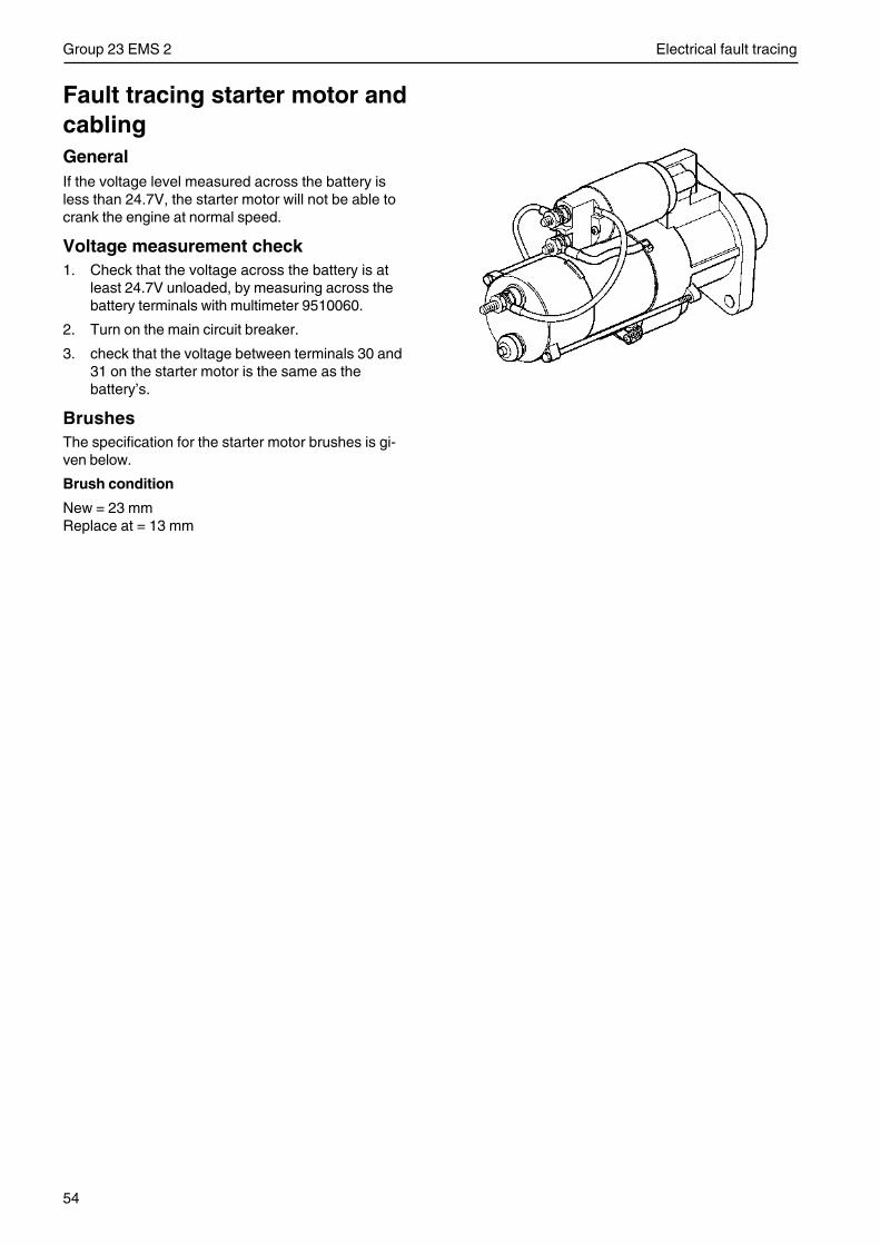
54
Group 23 EMS 2 Electrical fault tracing
Fault tracing starter motor andcablingGeneralIf the voltage level measured across the battery isless than 24.7V, the starter motor will not be able tocrank the engine at normal speed.
Voltage measurement check1. Check that the voltage across the battery is at
least 24.7V unloaded, by measuring across thebattery terminals with multimeter 9510060.
2. Turn on the main circuit breaker.
3. check that the voltage between terminals 30 and31 on the starter motor is the same as thebattery’s.
BrushesThe specification for the starter motor brushes is gi-ven below.
Brush condition
New = 23 mmReplace at = 13 mm
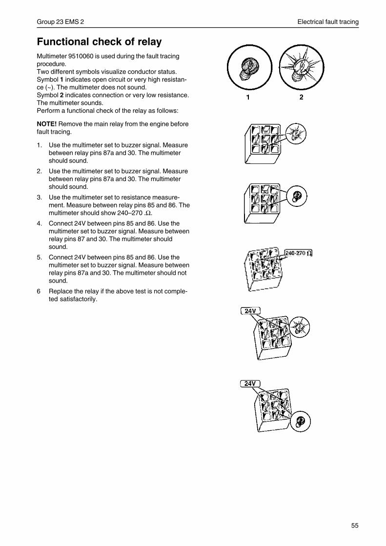
55
Group 23 EMS 2 Electrical fault tracing
Functional check of relayMultimeter 9510060 is used during the fault tracingprocedure.Two different symbols visualize conductor status.Symbol 1 indicates open circuit or very high resistan-ce (~). The multimeter does not sound.Symbol 2 indicates connection or very low resistance.The multimeter sounds.Perform a functional check of the relay as follows:
NOTE! Remove the main relay from the engine beforefault tracing.
1. Use the multimeter set to buzzer signal. Measurebetween relay pins 87a and 30. The multimetershould sound.
2. Use the multimeter set to buzzer signal. Measurebetween relay pins 87a and 30. The multimetershould sound.
3. Use the multimeter set to resistance measure-ment. Measure between relay pins 85 and 86. Themultimeter should show 240–270 .Ω.
4. Connect 24V between pins 85 and 86. Use themultimeter set to buzzer signal. Measure betweenrelay pins 87 and 30. The multimeter shouldsound.
5. Connect 24V between pins 85 and 86. Use themultimeter set to buzzer signal. Measure betweenrelay pins 87a and 30. The multimeter should notsound.
6 Replace the relay if the above test is not comple-ted satisfactorily.
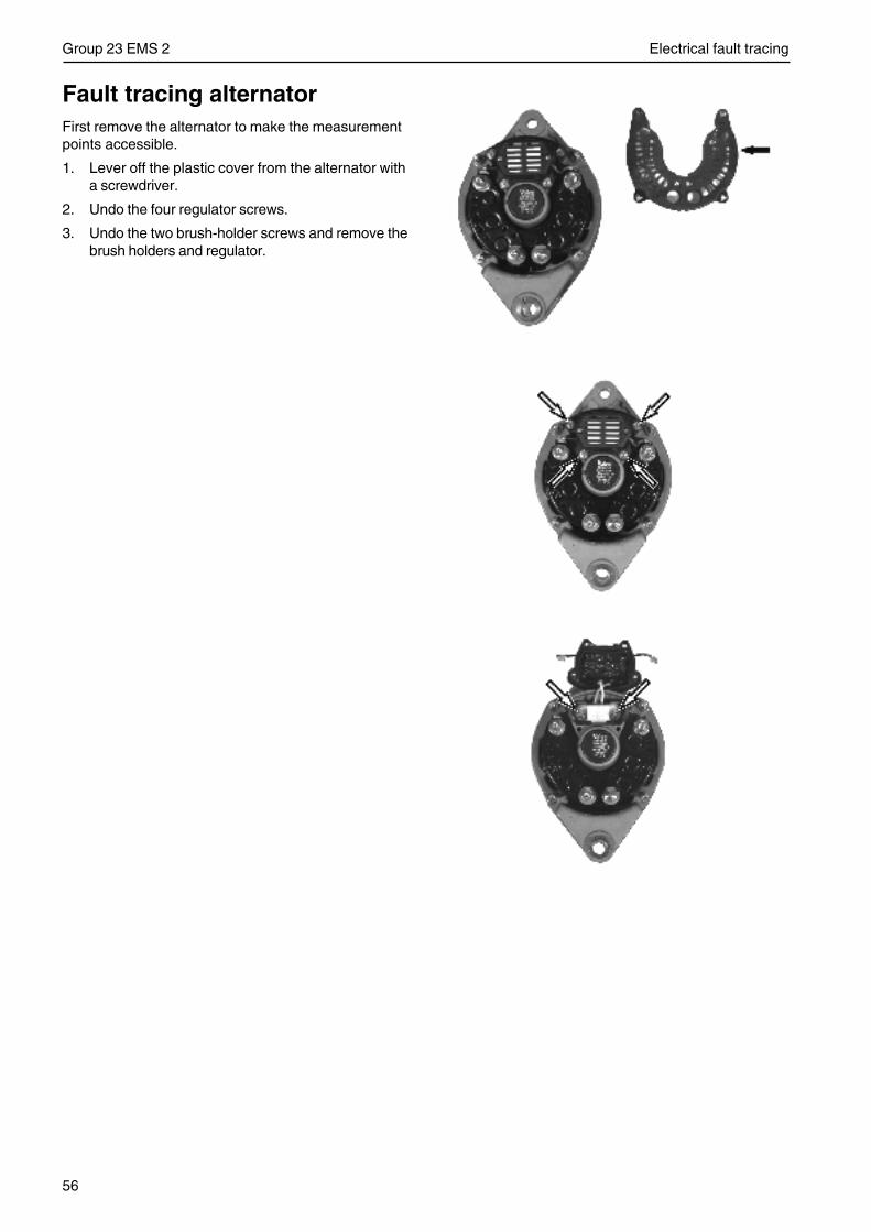
56
Group 23 EMS 2 Electrical fault tracing
Fault tracing alternatorFirst remove the alternator to make the measurementpoints accessible.
1. Lever off the plastic cover from the alternator witha screwdriver.
2. Undo the four regulator screws.
3. Undo the two brush-holder screws and remove thebrush holders and regulator.
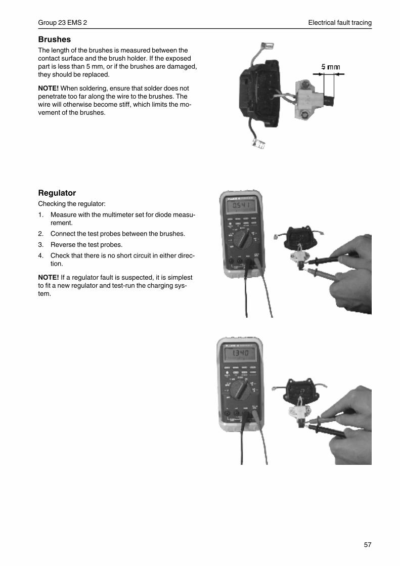
57
Group 23 EMS 2 Electrical fault tracing
BrushesThe length of the brushes is measured between thecontact surface and the brush holder. If the exposedpart is less than 5 mm, or if the brushes are damaged,they should be replaced.
NOTE! When soldering, ensure that solder does notpenetrate too far along the wire to the brushes. Thewire will otherwise become stiff, which limits the mo-vement of the brushes.
RegulatorChecking the regulator:
1. Measure with the multimeter set for diode measu-rement.
2. Connect the test probes between the brushes.
3. Reverse the test probes.
4. Check that there is no short circuit in either direc-tion.
NOTE! If a regulator fault is suspected, it is simplestto fit a new regulator and test-run the charging sys-tem.
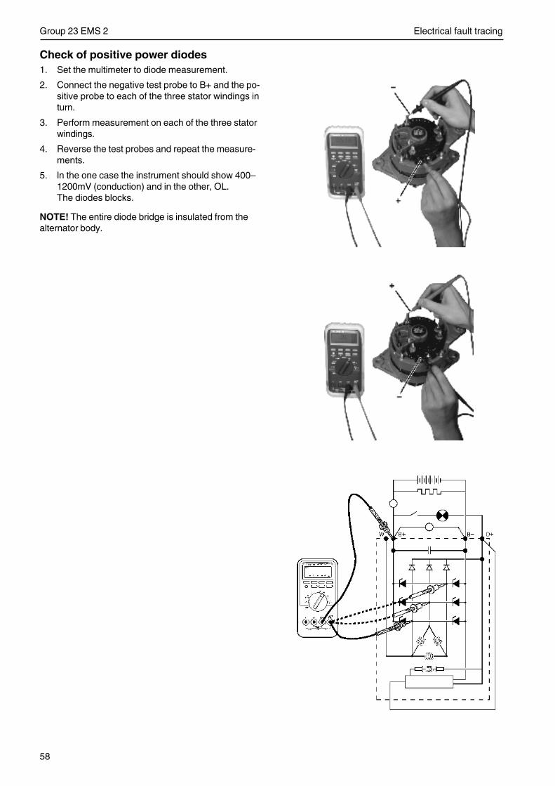
58
Group 23 EMS 2 Electrical fault tracing
Check of positive power diodes1. Set the multimeter to diode measurement.
2. Connect the negative test probe to B+ and the po-sitive probe to each of the three stator windings inturn.
3. Perform measurement on each of the three statorwindings.
4. Reverse the test probes and repeat the measure-ments.
5. ln the one case the instrument should show 400–1200mV (conduction) and in the other, OL.The diodes blocks.
NOTE! The entire diode bridge is insulated from thealternator body.
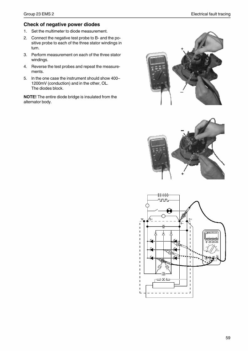
59
Group 23 EMS 2 Electrical fault tracing
Check of negative power diodes1. Set the multimeter to diode measurement.
2. Connect the negative test probe to B- and the po-sitive probe to each of the three stator windings inturn.
3. Perform measurement on each of the three statorwindings.
4. Reverse the test probes and repeat the measure-ments.
5. ln the one case the instrument should show 400–1200mV (conduction) and in the other, OL.The diodes block.
NOTE! The entire diode bridge is insulated from thealternator body.
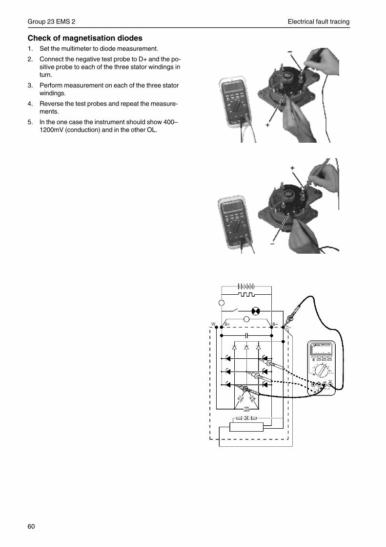
60
Group 23 EMS 2 Electrical fault tracing
Check of magnetisation diodes1. Set the multimeter to diode measurement.
2. Connect the negative test probe to D+ and the po-sitive probe to each of the three stator windings inturn.
3. Perform measurement on each of the three statorwindings.
4. Reverse the test probes and repeat the measure-ments.
5. ln the one case the instrument should show 400–1200mV (conduction) and in the other OL.
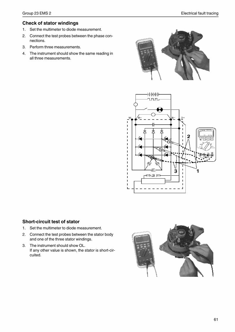
61
Group 23 EMS 2 Electrical fault tracing
Short-circuit test of stator1. Set the multimeter to diode measurement.
2. Connect the test probes between the stator bodyand one of the three stator windings.
3. The instrument should show OL.If any other value is shown, the stator is short-cir-cuited.
Check of stator windings1. Set the multimeter to diode measurement.
2. Connect the test probes between the phase con-nections.
3. Perform three measurements.
4. The instrument should show the same reading inall three measurements.
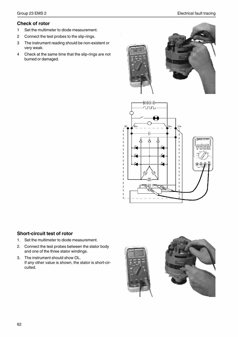
62
Group 23 EMS 2 Electrical fault tracing
Check of rotor1 Set the multimeter to diode measurement.
2 Connect the test probes to the slip-rings.
3 The instrument reading should be non-existent orvery weak.
4 Check at the same time that the slip-rings are notburned or damaged.
Short-circuit test of rotor1. Set the multimeter to diode measurement.
2. Connect the test probes between the stator bodyand one of the three stator windings.
3. The instrument should show OL.If any other value is shown, the stator is short-cir-cuited.

63
Group 23 EMS 2 Electrical system
Electrical system
Important information -electrical system
Important! Turn the engine off and turn off thepower at the main switch(es) before carrying outwork on the electrical system.
1. Battery main switchNever break the circuit between the alternator andthe battery while the engine is running.The main switches must never be disconnectedbefore the engine has been stopped.If the circuit is broken while the engine is running,the voltage regulator can be destroyed and the al-ternator badly damaged.Dis-/reconnection of the charging circuit should,for the same reason, never be performed while theengine is running. For simultaneous charging oftwo independent battery circuits, a Volvo Pentacharging separator can be fitted to the standardalternator (accessory).
2. BatteriesNever mix up the battery’s positive and negativeterminals when fitting batteries.Incorrect installation can result in serious damageto the electrical equipment.Refer to the wiring diagram. The battery terminalsshould be well cleaned and the terminal clampsgreased and properly tightened.
Fast charging of the batteries should be avoided.If fast charging must be performed, the ordinarybattery cables must be removed first.
NOTE: Follow the appropriate safety regulationswhen charging batteries.During charging, the cell covers should be loosenedbut not removed. Ventilate well, especially if the bat-teries are charged in an enclosed space.Always discontinue the charging current before dis-connecting the charging clips.
Warning! Never expose the battery area tonaked flame or electrical sparks. Never smokeclose to the batteries. The batteries generateoxy-hydrogen gas when charged, which formsan explosive gas when mixed with air. This gasis easily ignited and highly explosive.
Always use protective goggles when charging andhandling the batteries.Battery electrolyte contains sulfuric acid which ishighly corrosive.Should the battery electrolyte come into contact withunprotected skin wash off immediately using plenty ofwater. If battery acid comes in contact with the eyes,immediately flush with plenty of water and obtain med-ical assistance at once.
3. If starting with the help of auxiliary batteries, see”Starting with auxiliary batteries”.
4. Connecting extra equipment
All extra equipment shall be connected to a sepa-rate connection box and correctly fused.Extra power take-off directly from the instrumentpanel should be avoided. The permitted extra takeoff is however totally max. 5A (applies to all in-strument panels together).
Electric weldingRemove the positive and negative cables from thebatteries.Then disconnect all cables connected to the alterna-tor.
Then remove the cable connection from the controlunit, see instructions in ”Control unit (EMS 2), repla-ce”.
Always connect the welder ground clamp to the com-ponent to be welded, and as close as possible to theweld site. The clamp must never be connected to theengine or in such a way that current can pass througha bearing.
Important! After welding is finished, the discon-nected components such as cable connectors,alternator cables and battery cables must be re-fitted in the correct order.
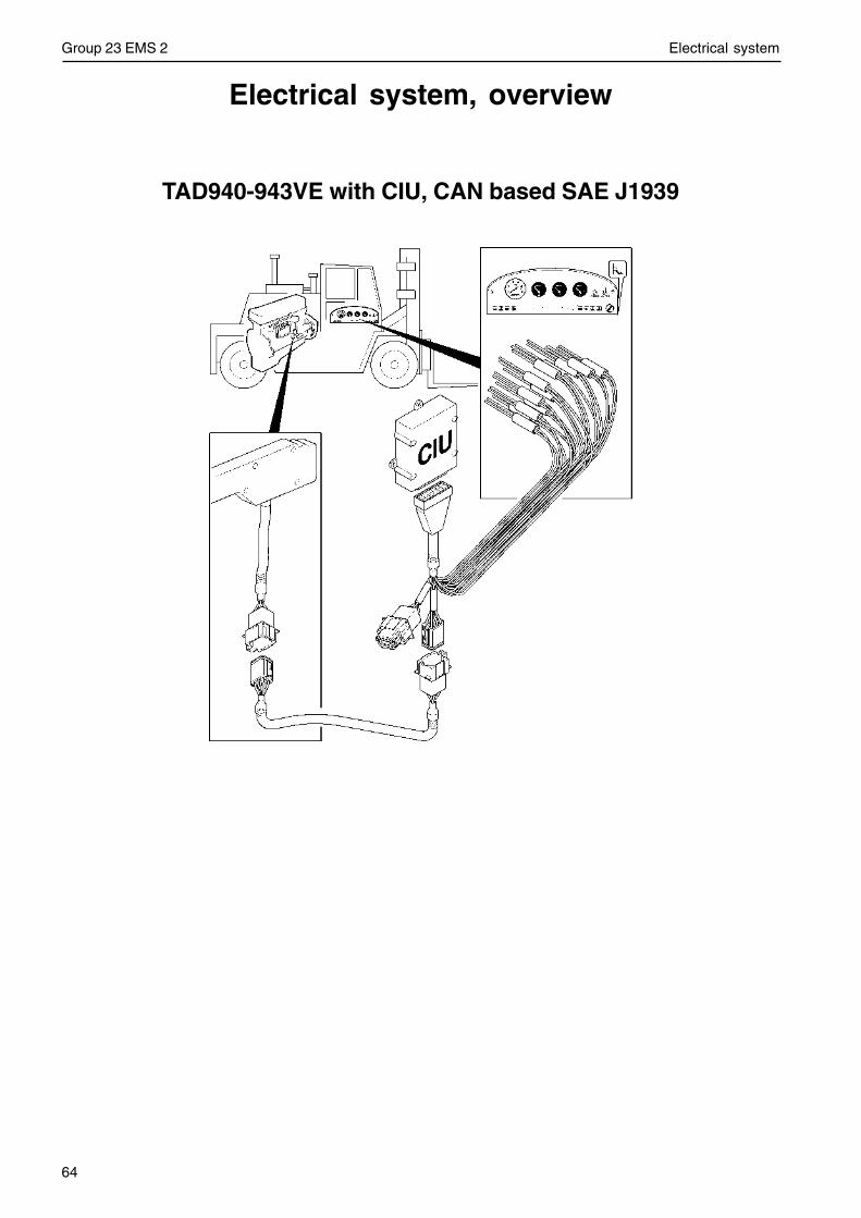
64
Group 23 EMS 2 Electrical system
Electrical system, overview
TAD940-943VE with CIU, CAN based SAE J1939
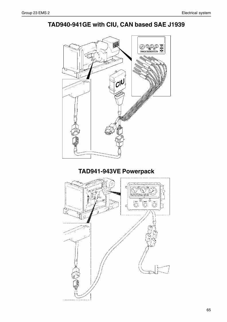
65
Group 23 EMS 2 Electrical system
TAD941-943VE Powerpack
TAD940-941GE with CIU, CAN based SAE J1939
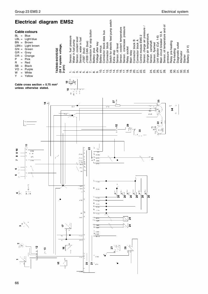
66
Group 23 EMS 2 Electrical system
TA
D94
0-94
3VE
/GE
(24
V s
yste
m v
olt
age,
2-p
in)
1.S
enso
r, f
uel
pres
sure
2.W
ater
in fu
el p
ump
3.S
enso
r, c
oola
nt l
evel
4.S
enso
r, w
ater
in f
uel
5.J1
587
(bus
)6.
J193
9 C
AN
(bu
s)7.
Con
nect
ion
for
stop
but
ton
8.B
atte
ry p
lus
9.V
olta
ge a
fter
key
10.
Bat
tery
min
us11
.C
onne
ctor
blo
ck d
ata
bus
12.
Con
nect
or b
lock
13.
Sw
itch
for
elec
tric
feed
pum
p sw
itch
14.
Ext
ra s
top
15.
Sen
sor,
oil
leve
l16
.S
enso
r, c
oola
nt t
empe
ratu
re17
.S
enso
r,
cran
kcas
e pr
essu
re18
.R
elay
soc
ket
19.
Mai
n re
lay
20.
Con
nect
or b
lock
B21
.C
onne
ctor
blo
ck A
22.
Con
trol
mod
ule
EM
S 2
23.
Sen
sor,
cha
rge
air
pres
sure
/ch
arg
eai
r te
mpe
ratu
re.
24.
Sen
sor,
cam
shaf
t25
.S
enso
r, f
lyw
heel
26.
Uni
t in
ject
or (
Cyl
. 1-
6)27
.M
ain
circ
uit
brea
ker
10 A
28.
Sen
sor,
oil
tem
pera
ture
and
oil
pre
ssu
re29
.R
elay
pre
-hea
ting
30.
Pre
-hea
ting
31.
Dia
gnos
tic o
utle
t32
.A
ltern
ator
33.
Sta
rter
34.
Bat
tery
(24
V)
Cable coloursBL = BlueLBL = Light blueBN = BrownLBN = Light brownGN = GreenGR = GreyOR = OrangeP = PinkR = RedSB = BlackVO = PurpleW = WhiteY = Yellow
Cable cross section = 0.75 mm2
unless otherwise stated.
Electrical diagram EMS2
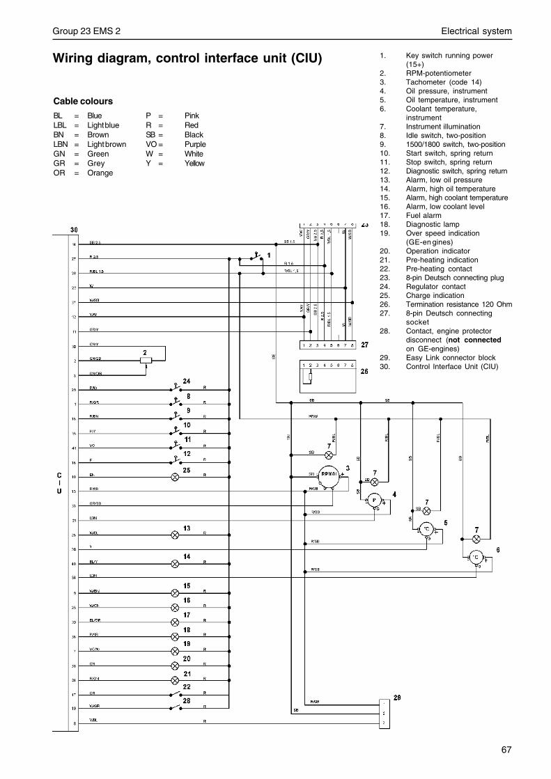
67
Group 23 EMS 2 Electrical system
Cable colours
BL = Blue P = PinkLBL = Light blue R = RedBN = Brown SB = BlackLBN = Light brown VO = PurpleGN = Green W = WhiteGR = Grey Y = YellowOR = Orange
Wiring diagram, control interface unit (CIU) 1. Key switch running power(15+)
2. RPM-potentiometer3. Tachometer (code 14)4. Oil pressure, instrument5. Oil temperature, instrument6. Coolant temperature,
instrument7. Instrument illumination8. Idle switch, two-position9. 1500/1800 switch, two-position10. Start switch, spring return11. Stop switch, spring return12. Diagnostic switch, spring return13. Alarm, low oil pressure14. Alarm, high oil temperature15. Alarm, high coolant temperature16. Alarm, low coolant level17. Fuel alarm18. Diagnostic lamp19. Over speed indication
(GE-en gines)20. Operation indicator21. Pre-heating indication22. Pre-heating contact23. 8-pin Deutsch connecting plug24. Regulator contact25. Charge indication26. Termination resistance 120 Ohm27. 8-pin Deutsch connecting
socket28. Contact, engine protector
disconnect (not connectedon GE-engines)
29. Easy Link connector block30. Control Interface Unit (CIU)
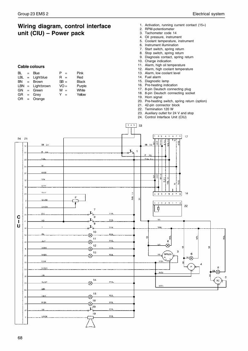
68
Group 23 EMS 2 Electrical system
Cable colours
BL = Blue P = PinkLBL = Light blue R = RedBN = Brown SB = BlackLBN = Light brown VO = PurpleGN = Green W = WhiteGR = Grey Y = YellowOR = Orange
Wiring diagram, control interfaceunit (CIU) – Power pack
1. Activation, running current contact (15+)2. RPM-potentiometer3. Tachometer code 144. Oil pressure, instrument5. Coolant temperature, instrument6. Instrument illumination7. Start switch, spring return8. Stop switch, spring return9. Diagnosis contact, spring return
10. Charge indication11. Alarm, high oil temperature12. Alarm, high coolant temperature13. Alarm, low coolant level14. Fuel alarm15. Diagnostic lamp16. Pre-heating indication17. 8-pin Deutsch connecting plug18. 8-pin Deutsch connecting socket19. Horn signal20. Pre-heating switch, spring return (option)21. 42-pin connector block22. Termination 120 W23. Auxiliary outlet for 24 V and stop24. Control Interface Unit (CIU)
Report form
Do you have any complaints or other comments about this manual? Please makea copy of this page, write your comments down and post it to us. The address is atthe bottom of the page. We would prefer you to write in English or Swedish.
From: ............................................................................
......................................................................................
......................................................................................
......................................................................................
Refers to publication: .............................................................................................................................................
Publication no.: ..................................................................... Issued: ....................................................................
Suggestion/reasons: ..............................................................................................................................................
..............................................................................................................................................................................
..............................................................................................................................................................................
..............................................................................................................................................................................
..............................................................................................................................................................................
..............................................................................................................................................................................
..............................................................................................................................................................................
..............................................................................................................................................................................
..............................................................................................................................................................................
Date: ...........................................................
Name: .........................................................
AB Volvo PentaCustomer Support
Dept. 42200SE-405 08 Gothenburg
Sweden

7746
032
E
nglis
h 0
9-20
04