vrf selection tool software - toshiba
TRANSCRIPT
© 2018 Toshiba Carrier Corporation
Toshiba Carrier CorporationTCEU Pre-Sales DivisionOctober 26, 2018
Scope of Disclosure Distributions
Owner Toshiba Carrier Corporation
VRF Selection Tool Software
v1.2.19
2© 2018 Toshiba Carrier Corporation
Index
1. Introduction
2. Set up
3. New Project
4. Design Window
5. System Design
6. Central Controllers
7. Output
3© 2018 Toshiba Carrier Corporation
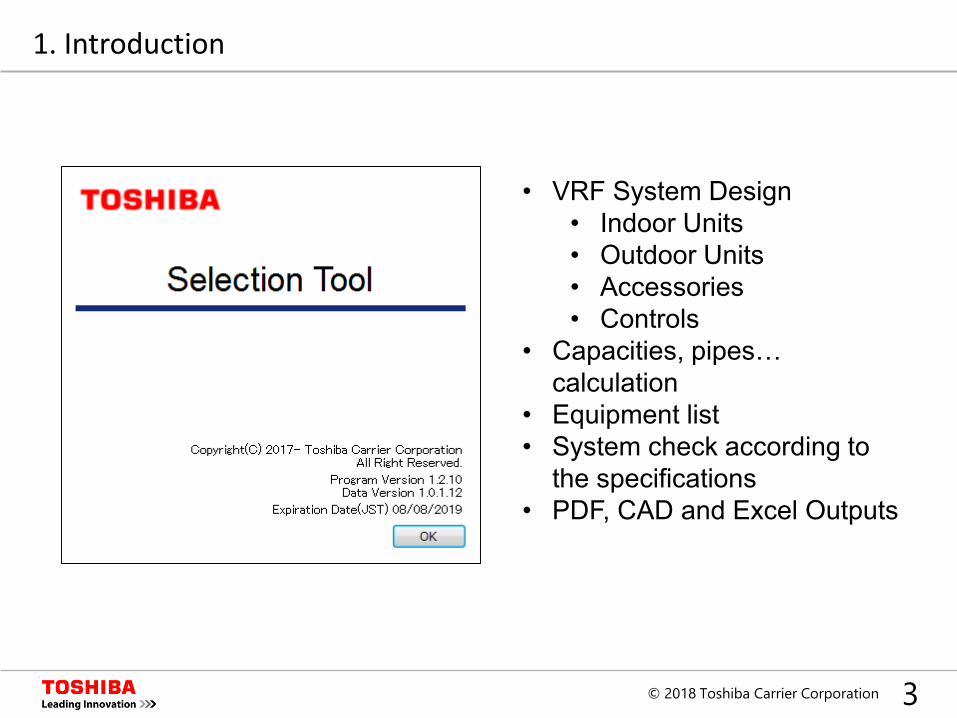
• VRF System Design• Indoor Units• Outdoor Units• Accessories• Controls
• Capacities, pipes… calculation
• Equipment list• System check according to
the specifications• PDF, CAD and Excel Outputs
1. Introduction
4© 2018 Toshiba Carrier Corporation
Item Description
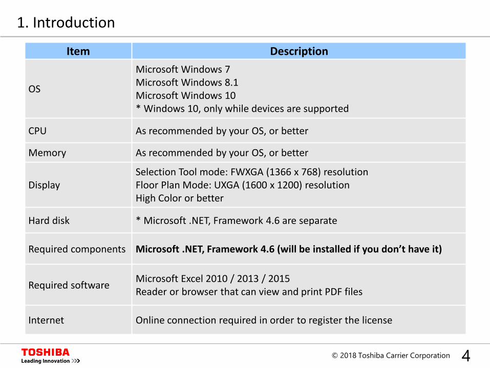
OS
Microsoft Windows 7Microsoft Windows 8.1Microsoft Windows 10* Windows 10, only while devices are supported
CPU As recommended by your OS, or better
Memory As recommended by your OS, or better
DisplaySelection Tool mode: FWXGA (1366 x 768) resolutionFloor Plan Mode: UXGA (1600 x 1200) resolutionHigh Color or better
Hard disk * Microsoft .NET, Framework 4.6 are separate
Required components Microsoft .NET, Framework 4.6 (will be installed if you don’t have it)
Required software Microsoft Excel 2010 / 2013 / 2015Reader or browser that can view and print PDF files
Internet Online connection required in order to register the license
1. Introduction
5© 2018 Toshiba Carrier Corporation
1. Introduction
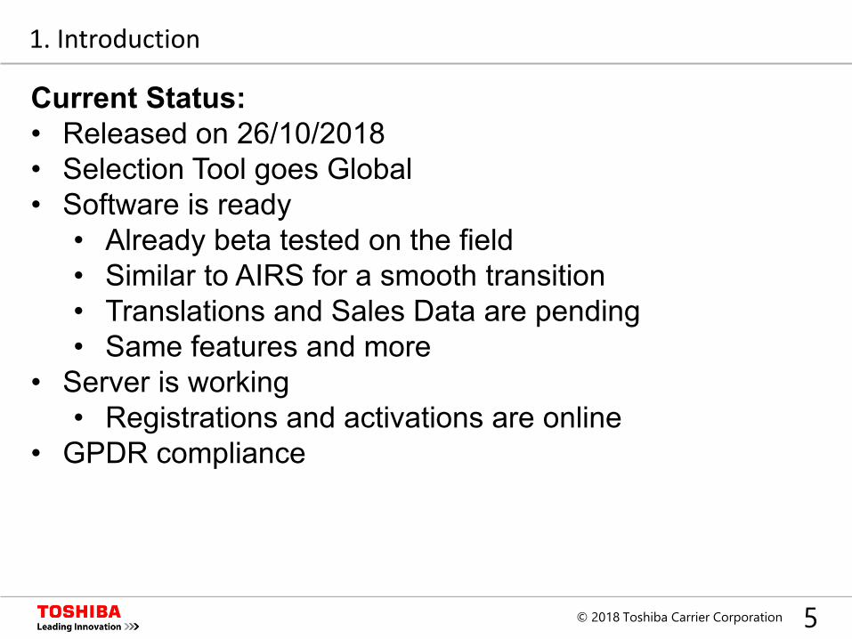
Current Status:• Released on 26/10/2018• Selection Tool goes Global• Software is ready
• Already beta tested on the field• Similar to AIRS for a smooth transition• Translations and Sales Data are pending• Same features and more
• Server is working• Registrations and activations are online
• GPDR compliance
6© 2018 Toshiba Carrier Corporation
Index
1. Introduction
2. Set up
3. New Project
4. Design Window
5. System Design
6. Central Controllers
7. Output
7© 2018 Toshiba Carrier Corporation
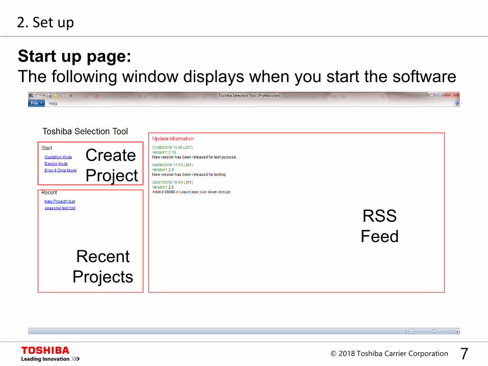
Create Project
Recent Projects
RSS Feed
Start up page:The following window displays when you start the software
2. Set up
8© 2018 Toshiba Carrier Corporation
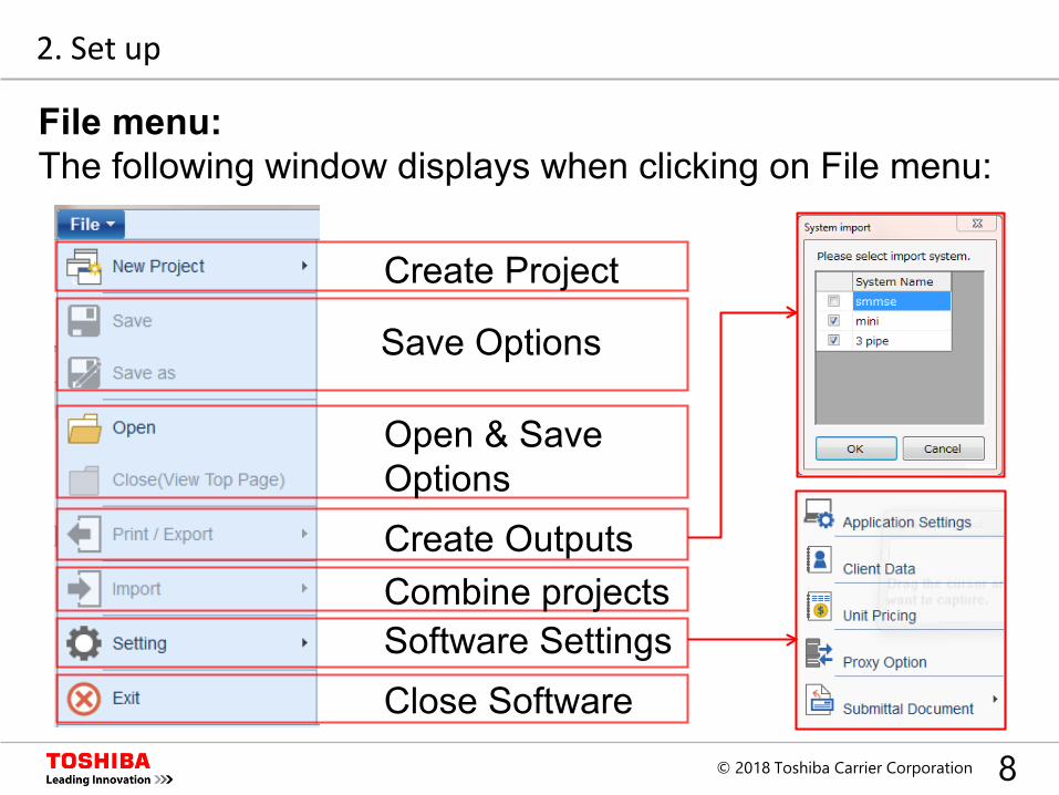
Create Project
Save Options
Open & Save Options
Combine projectsCreate Outputs
Close SoftwareSoftware Settings
2. Set up
File menu:The following window displays when clicking on File menu:
9© 2018 Toshiba Carrier Corporation
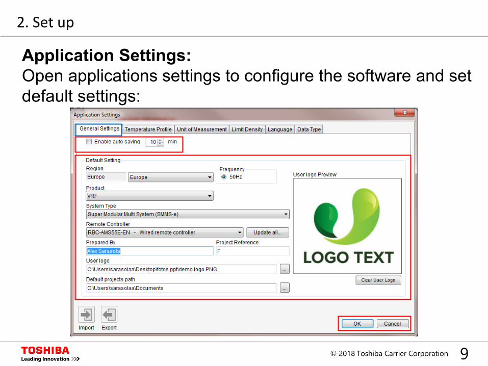
Application Settings:Open applications settings to configure the software and set default settings:
2. Set up
10© 2018 Toshiba Carrier Corporation
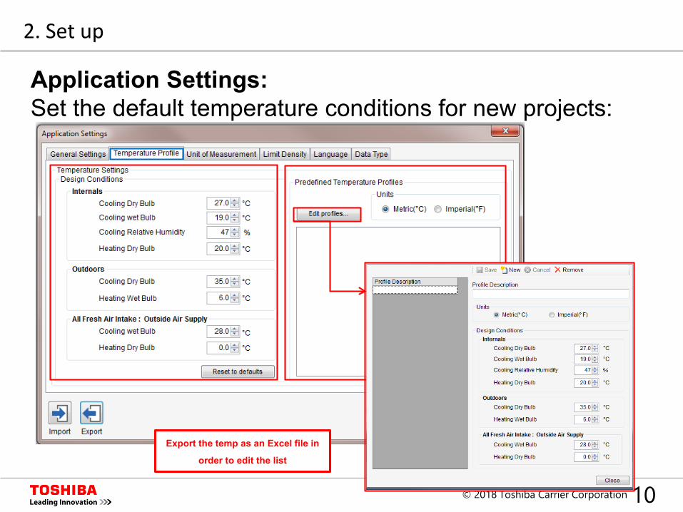
Application Settings:Set the default temperature conditions for new projects:
2. Set up
Export the temp as an Excel file in
order to edit the list
11© 2018 Toshiba Carrier Corporation
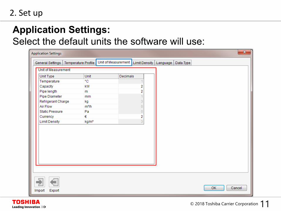
Application Settings:Select the default units the software will use:
2. Set up
12© 2018 Toshiba Carrier Corporation
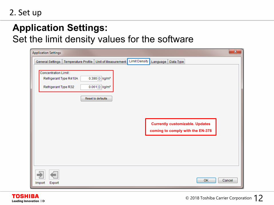
Application Settings:Set the limit density values for the software
2. Set up
Currently customizable. Updates
coming to comply with the EN-378
13© 2018 Toshiba Carrier Corporation
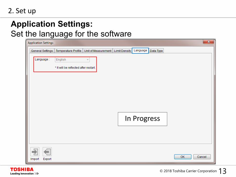
In Progress
Application Settings:Set the language for the software
2. Set up
14© 2018 Toshiba Carrier Corporation
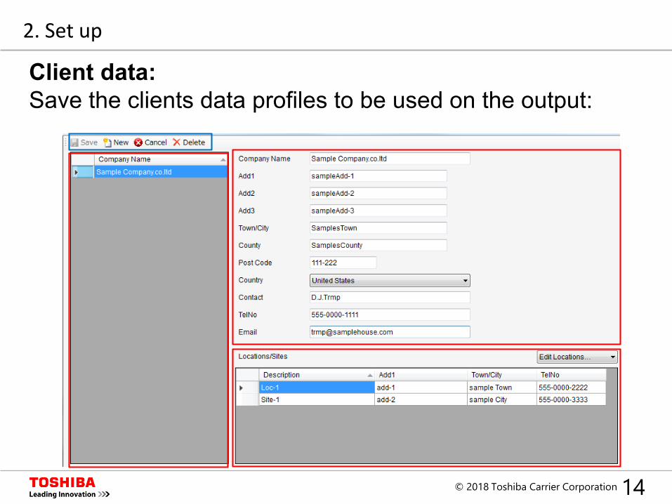
Client data:Save the clients data profiles to be used on the output:
2. Set up
15© 2018 Toshiba Carrier Corporation
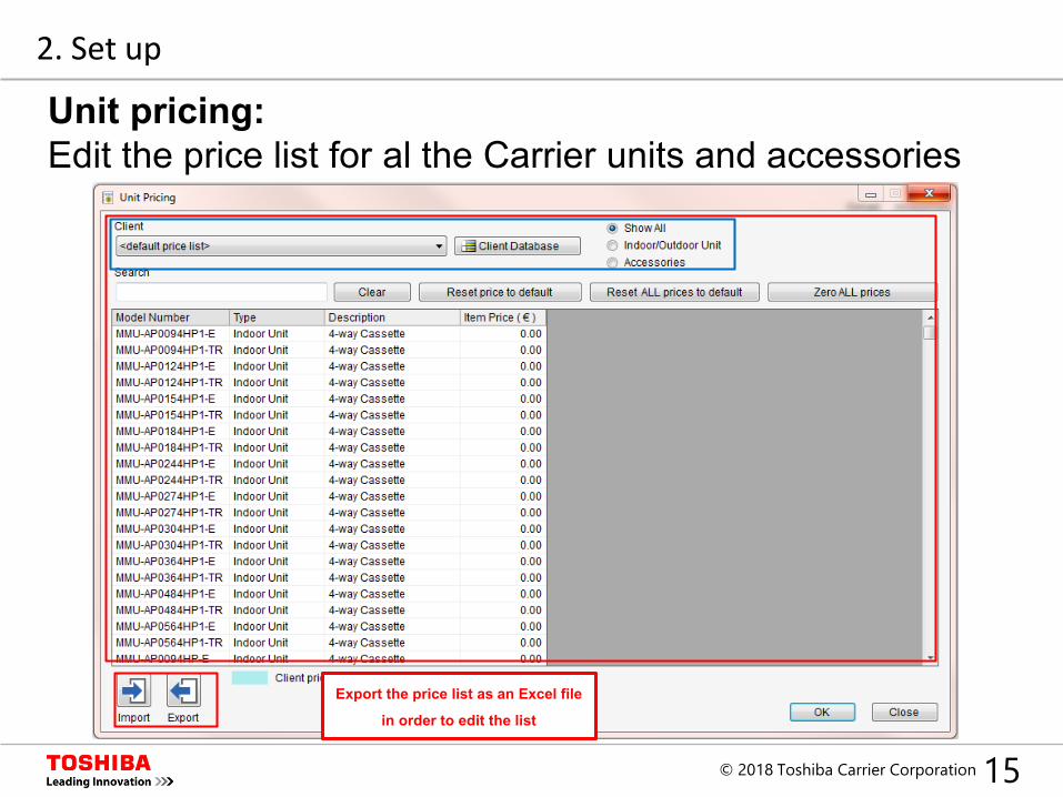
Export the price list as an Excel file
in order to edit the list
Unit pricing:Edit the price list for al the Carrier units and accessories
2. Set up

16© 2018 Toshiba Carrier Corporation
Index
1. Introduction
2. Set up
3. New Project
4. Design Window
5. System Design
6. Central Controllers
7. Output
17© 2018 Toshiba Carrier Corporation
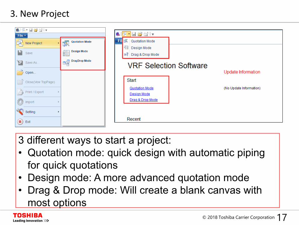
3 different ways to start a project:• Quotation mode: quick design with automatic piping
for quick quotations• Design mode: A more advanced quotation mode• Drag & Drop mode: Will create a blank canvas with
most options
3. New Project
18© 2018 Toshiba Carrier Corporation
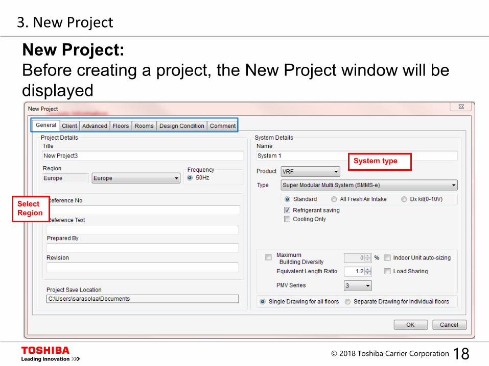
Select Region
System type
New Project:Before creating a project, the New Project window will be displayed
3. New Project
19© 2018 Toshiba Carrier Corporation
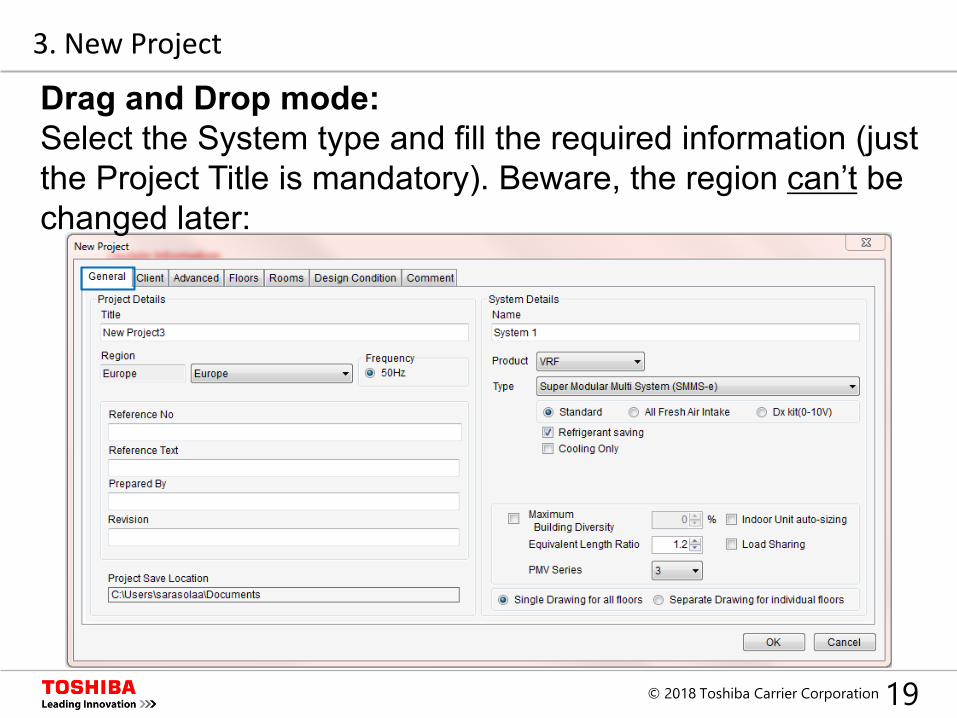
Drag and Drop mode:Select the System type and fill the required information (just the Project Title is mandatory). Beware, the region can’t be changed later:
3. New Project
20© 2018 Toshiba Carrier Corporation
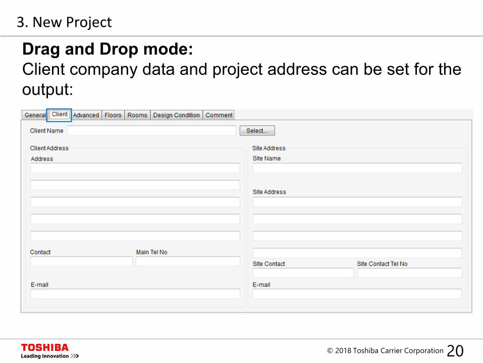
Drag and Drop mode:Client company data and project address can be set for the output:
3. New Project
21© 2018 Toshiba Carrier Corporation
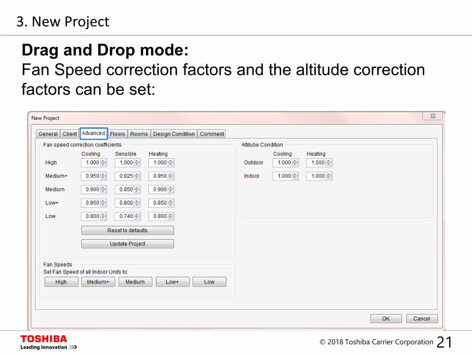
Drag and Drop mode:Fan Speed correction factors and the altitude correction factors can be set:
3. New Project
22© 2018 Toshiba Carrier Corporation
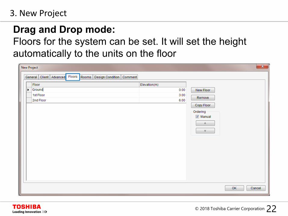
Drag and Drop mode:Floors for the system can be set. It will set the height automatically to the units on the floor
3. New Project
23© 2018 Toshiba Carrier Corporation
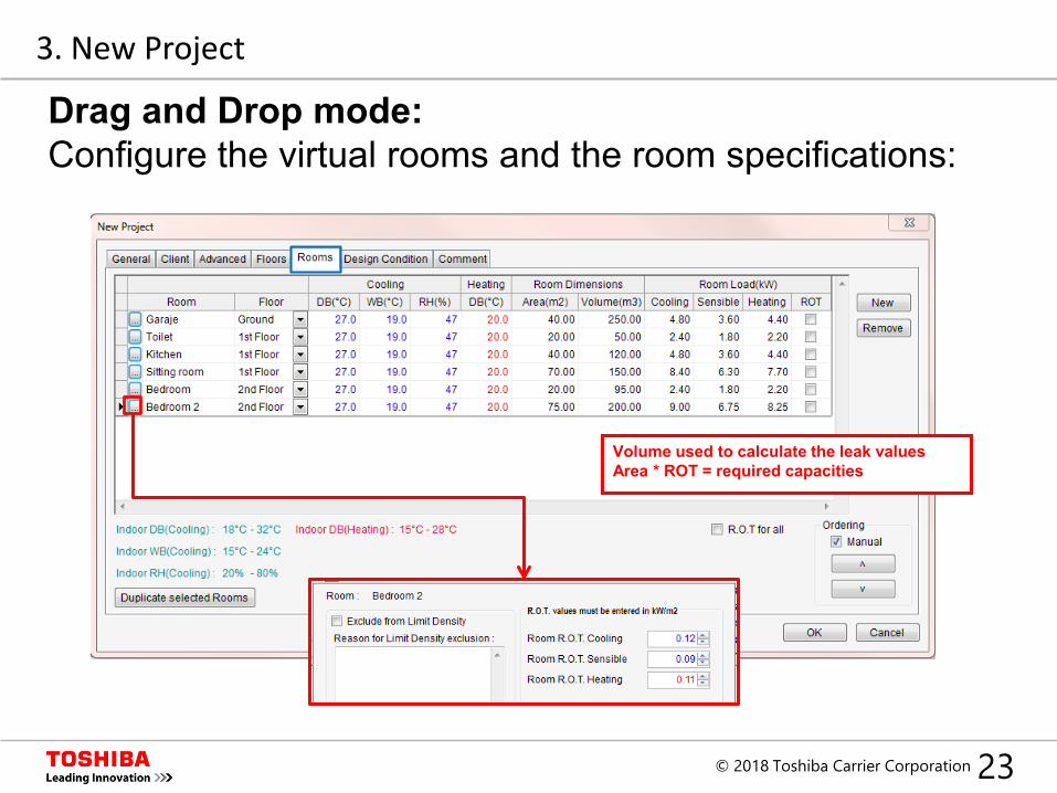
Drag and Drop mode:Configure the virtual rooms and the room specifications:
3. New Project
Volume used to calculate the leak valuesArea * ROT = required capacities
24© 2018 Toshiba Carrier Corporation
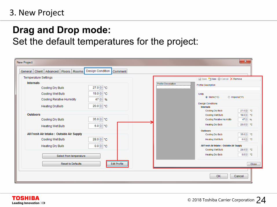
Drag and Drop mode:Set the default temperatures for the project:
3. New Project
25© 2018 Toshiba Carrier Corporation
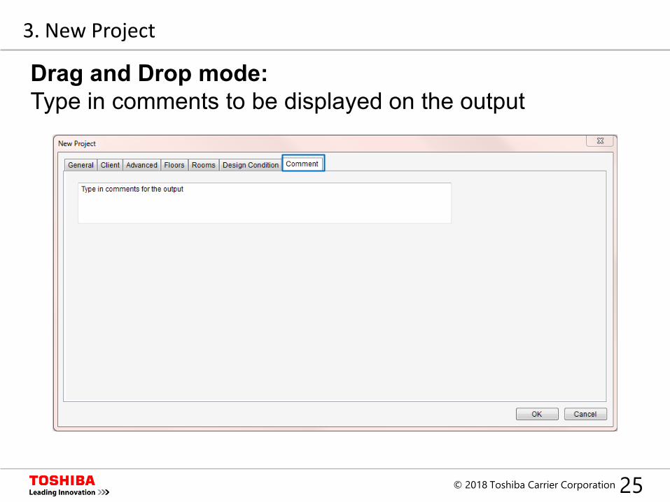
Drag and Drop mode:Type in comments to be displayed on the output
3. New Project
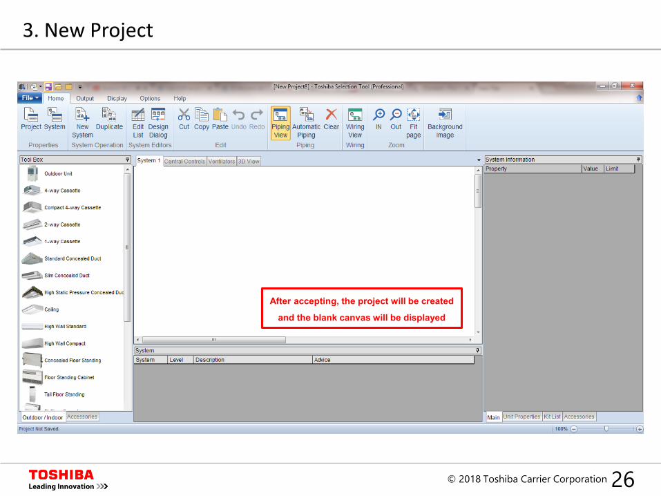
26© 2018 Toshiba Carrier Corporation
After accepting, the project will be created
and the blank canvas will be displayed
3. New Project
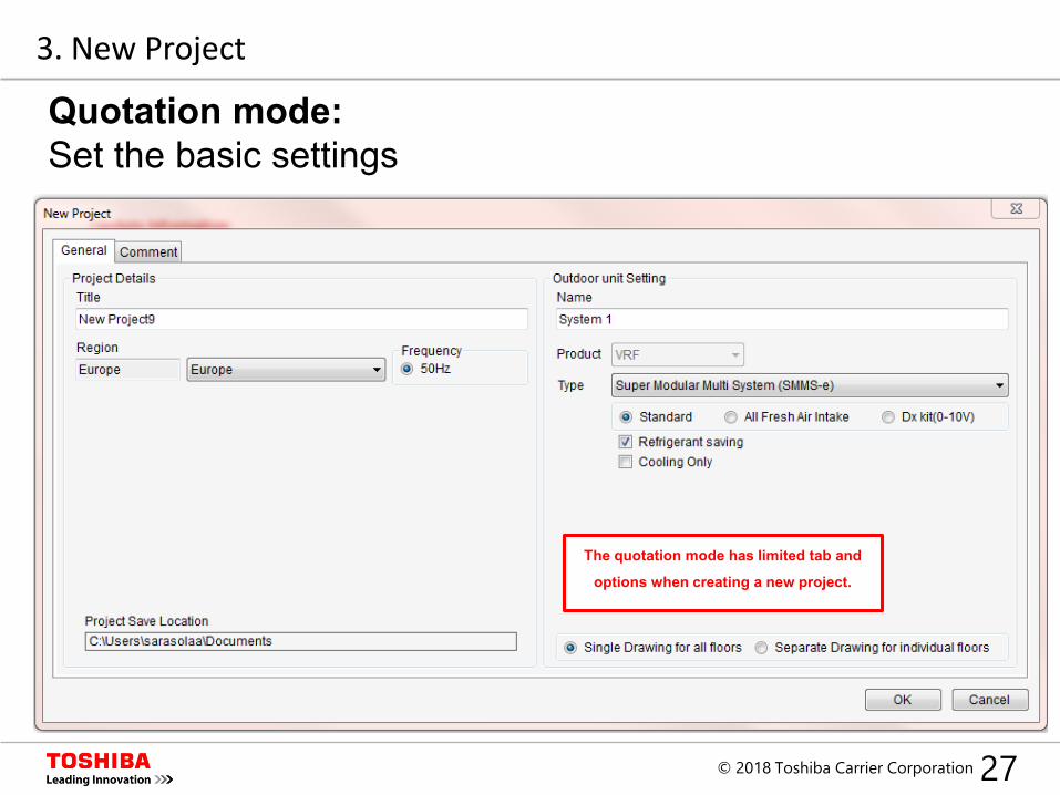
27© 2018 Toshiba Carrier Corporation
The quotation mode has limited tab and
options when creating a new project.
3. New Project
Quotation mode:Set the basic settings
28© 2018 Toshiba Carrier Corporation
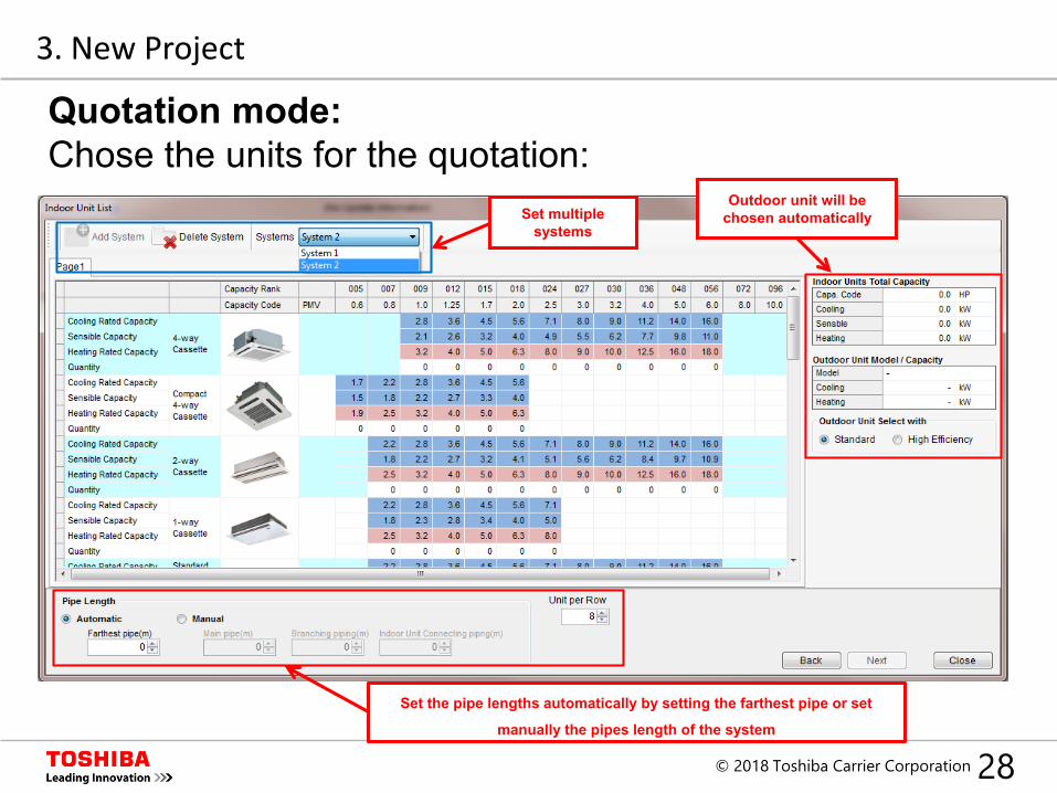
Outdoor unit will be chosen automatically
Set the pipe lengths automatically by setting the farthest pipe or set
manually the pipes length of the system
Set multiple systems
3. New Project
Quotation mode:Chose the units for the quotation:
29© 2018 Toshiba Carrier Corporation
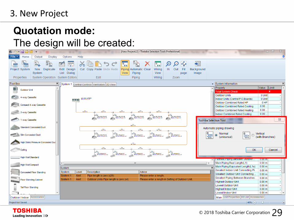
3. New Project
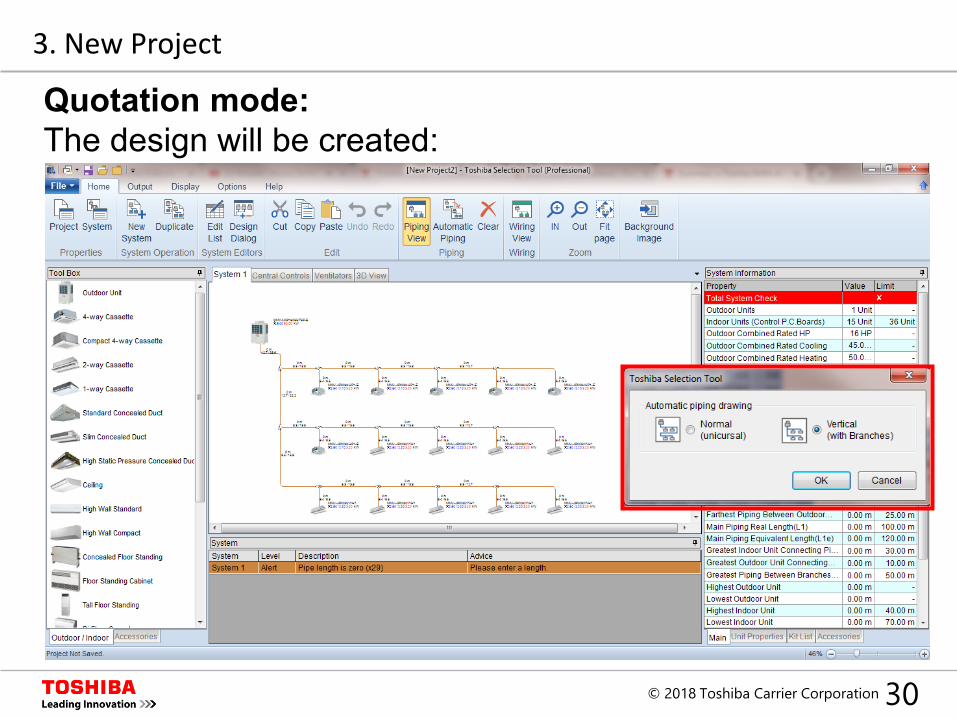
Quotation mode:The design will be created:
30© 2018 Toshiba Carrier Corporation
3. New Project
Quotation mode:The design will be created:
31© 2018 Toshiba Carrier Corporation
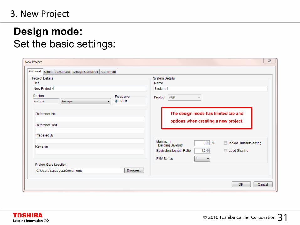
The design mode has limited tab and
options when creating a new project.
3. New Project
Design mode:Set the basic settings:
32© 2018 Toshiba Carrier Corporation
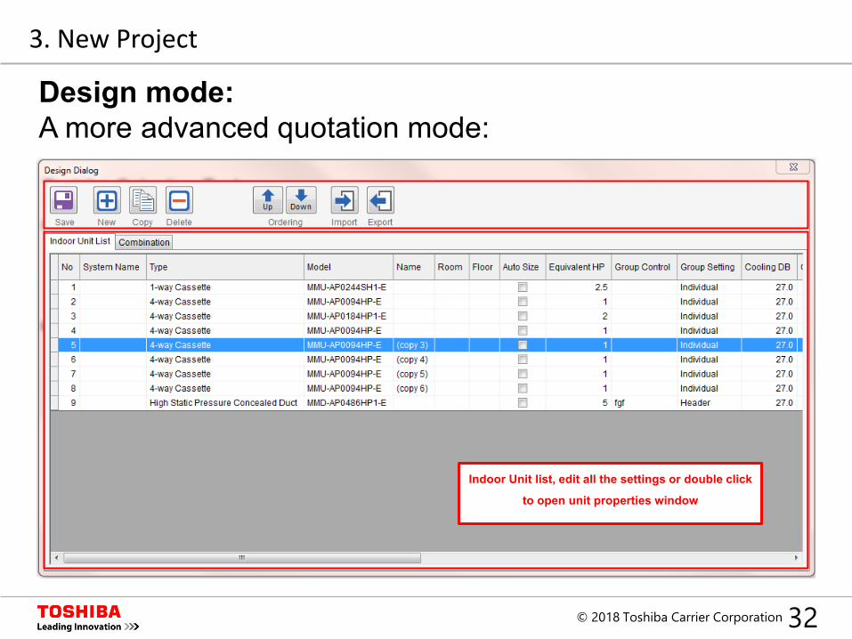
Indoor Unit list, edit all the settings or double click
to open unit properties window
Design mode:A more advanced quotation mode:
3. New Project
33© 2018 Toshiba Carrier Corporation
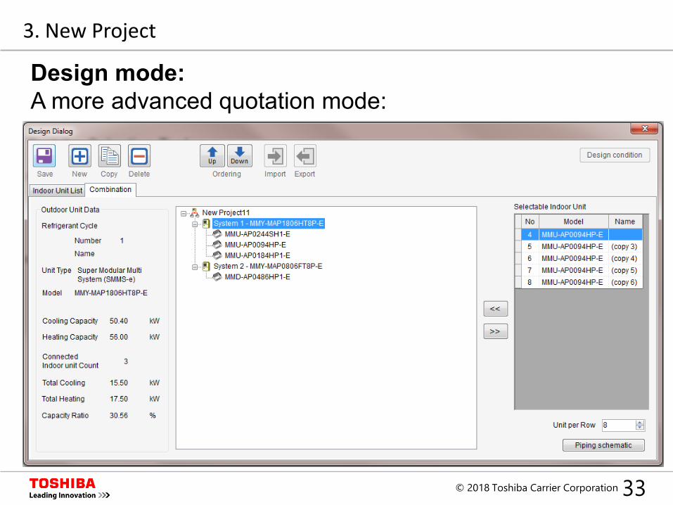
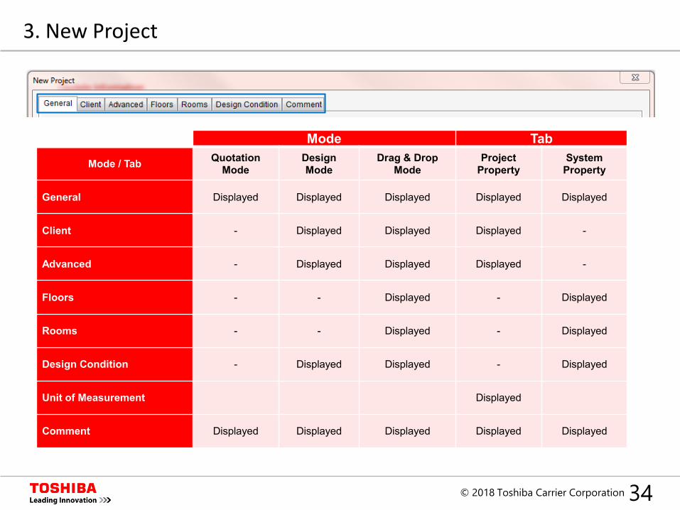
3. New Project
Design mode:A more advanced quotation mode:
34© 2018 Toshiba Carrier Corporation
Mode Tab
Mode / Tab Quotation Mode
DesignMode
Drag & DropMode
ProjectProperty
SystemProperty
General Displayed Displayed Displayed Displayed Displayed
Client - Displayed Displayed Displayed -
Advanced - Displayed Displayed Displayed -
Floors - - Displayed - Displayed
Rooms - - Displayed - Displayed
Design Condition - Displayed Displayed - Displayed
Unit of Measurement Displayed
Comment Displayed Displayed Displayed Displayed Displayed
3. New Project
35© 2018 Toshiba Carrier Corporation
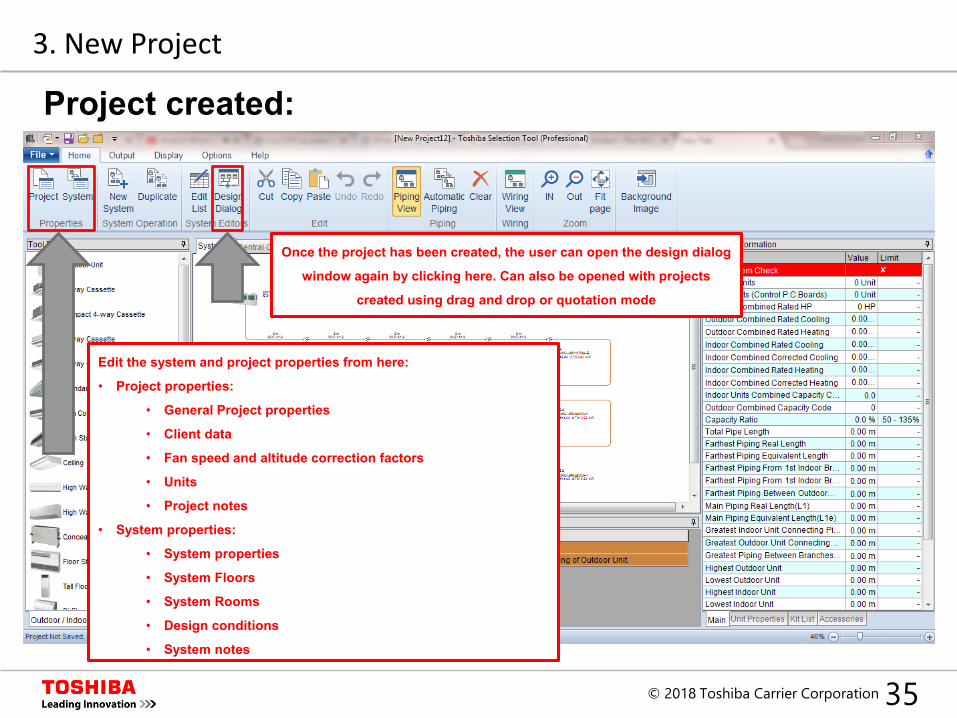
Once the project has been created, the user can open the design dialog
window again by clicking here. Can also be opened with projects
created using drag and drop or quotation mode
Edit the system and project properties from here:
• Project properties:
• General Project properties
• Client data
• Fan speed and altitude correction factors
• Units
• Project notes
• System properties:
• System properties
• System Floors
• System Rooms
• Design conditions
• System notes
3. New Project
Project created:
36© 2018 Toshiba Carrier Corporation
Index
1. Introduction
2. Set up
3. New Project
4. Design Window
5. System Design
6. Central Controllers
7. Output
37© 2018 Toshiba Carrier Corporation
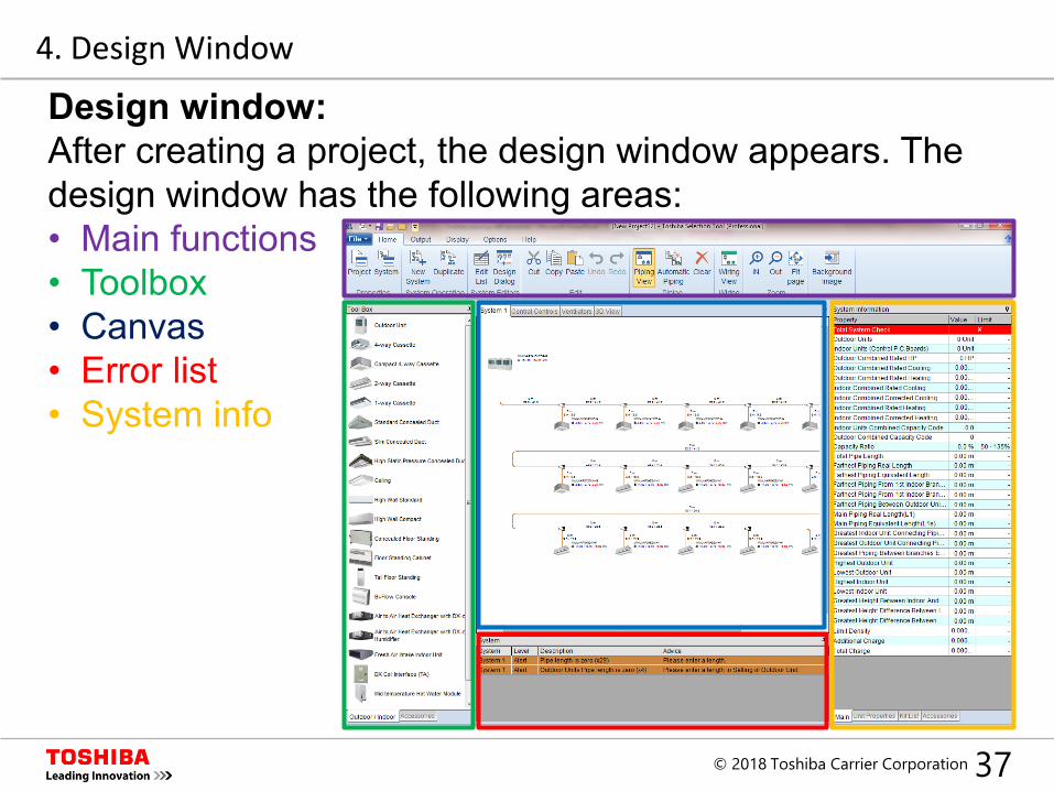
Design window:After creating a project, the design window appears. The design window has the following areas:• Main functions• Toolbox• Canvas• Error list• System info
4. Design Window
38© 2018 Toshiba Carrier Corporation
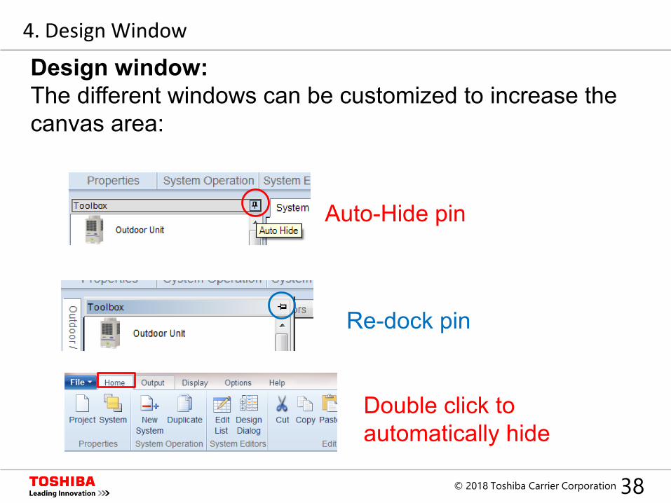
Design window:The different windows can be customized to increase the canvas area:
Re-dock pin
Auto-Hide pin
Double click to automatically hide
4. Design Window
39© 2018 Toshiba Carrier Corporation
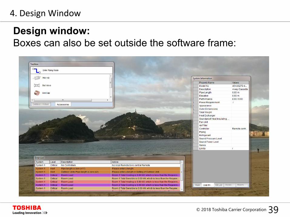
Design window:Boxes can also be set outside the software frame:
4. Design Window
40© 2018 Toshiba Carrier Corporation
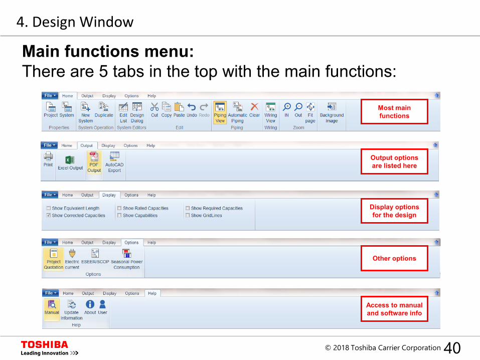
Main functions menu:There are 5 tabs in the top with the main functions:
Access to manual and software info
Most main functions
Output options are listed here
Display options for the design
Other options
4. Design Window
41© 2018 Toshiba Carrier Corporation
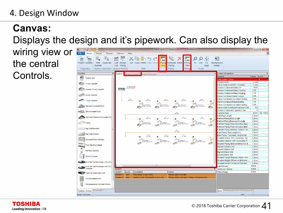
Canvas:Displays the design and it’s pipework. Can also display the wiring view orthe central Controls.
4. Design Window
42© 2018 Toshiba Carrier Corporation
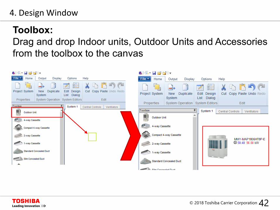
Toolbox:Drag and drop Indoor units, Outdoor Units and Accessories from the toolbox to the canvas
4. Design Window
43© 2018 Toshiba Carrier Corporation
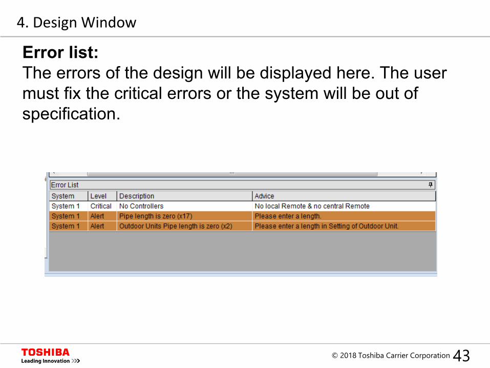
Error list:The errors of the design will be displayed here. The user must fix the critical errors or the system will be out of specification.
4. Design Window
44© 2018 Toshiba Carrier Corporation
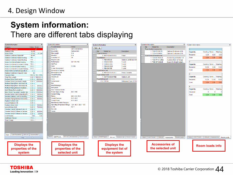
System information:There are different tabs displaying
Room loads infoAccessories of the selected unit
Displays the equipment list of
the system
Displays the properties of the
selected unit
Displays the properties of the
system
4. Design Window
45© 2018 Toshiba Carrier Corporation
Index
1. Introduction
2. Set up
3. New Project
4. Design Window
5. System Design
6. Central Controllers
7. Output
46© 2018 Toshiba Carrier Corporation
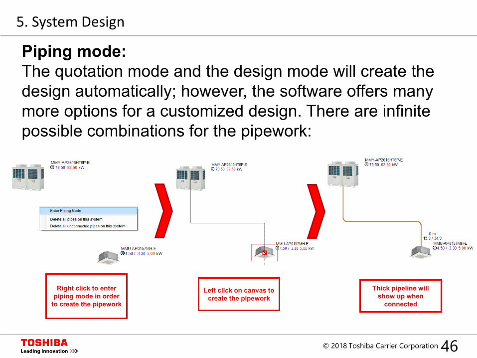
Piping mode:The quotation mode and the design mode will create the design automatically; however, the software offers many more options for a customized design. There are infinite possible combinations for the pipework:
Right click to enter piping mode in order
to create the pipework
Left click on canvas to create the pipework
Thick pipeline will show up when
connected
5. System Design
47© 2018 Toshiba Carrier Corporation
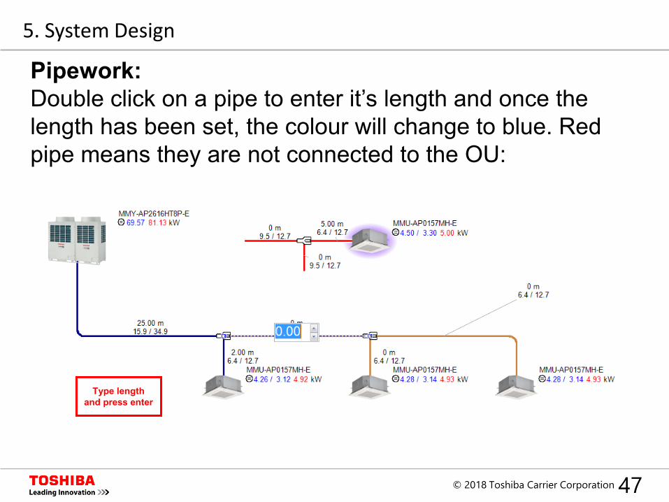
Pipework:Double click on a pipe to enter it’s length and once the length has been set, the colour will change to blue. Red pipe means they are not connected to the OU:
Type length and press enter
5. System Design
48© 2018 Toshiba Carrier Corporation
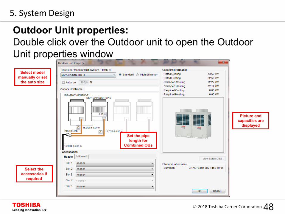
Outdoor Unit properties:Double click over the Outdoor unit to open the Outdoor Unit properties window
Select model manually or set
the auto size
Set the pipe length for
Combined OUs
Select the accessories if
required
Picture and capacities are
displayed
5. System Design
49© 2018 Toshiba Carrier Corporation
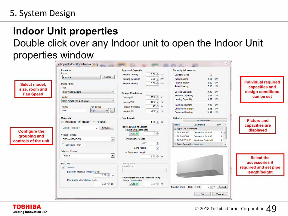
Indoor Unit propertiesDouble click over any Indoor unit to open the Indoor Unit properties window
Select model, size, room and
Fan Speed
Individual required capacities and
design conditions can be set
Configure thegrouping and
controls of the unit
Select the accessories if
required and set pipe length/height
Picture and capacities are
displayed
5. System Design
50© 2018 Toshiba Carrier Corporation
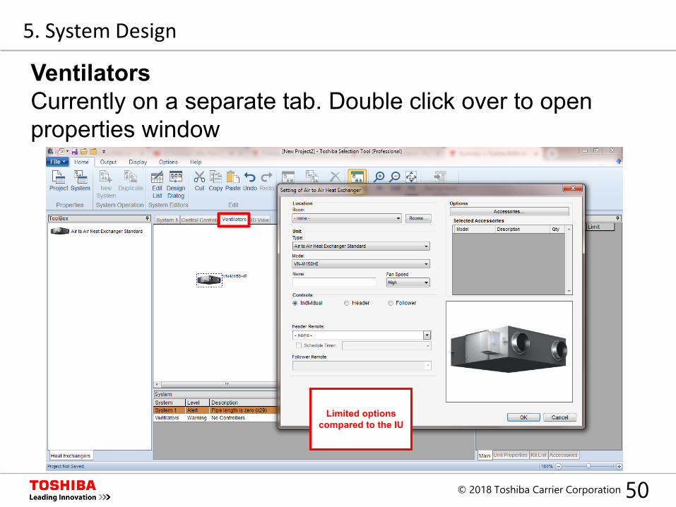
VentilatorsCurrently on a separate tab. Double click over to open properties window
Limited options compared to the IU
5. System Design
51© 2018 Toshiba Carrier Corporation
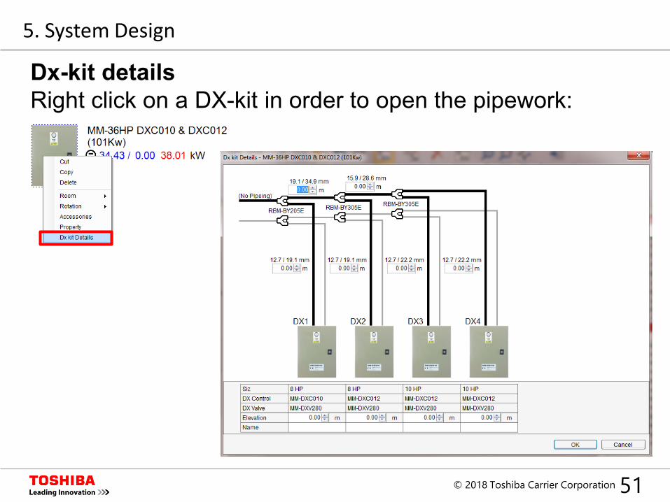
Dx-kit detailsRight click on a DX-kit in order to open the pipework:
Set internal pipe lenghts
5. System Design
52© 2018 Toshiba Carrier Corporation
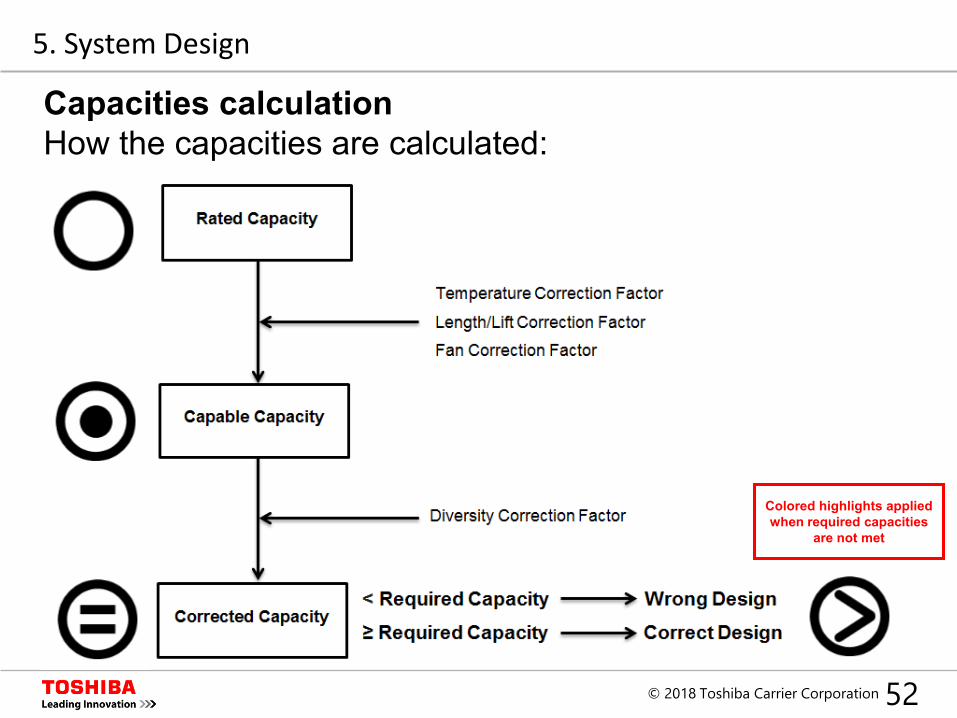
Capacities calculationHow the capacities are calculated:
Colored highlights applied when required capacities
are not met
5. System Design
53© 2018 Toshiba Carrier Corporation
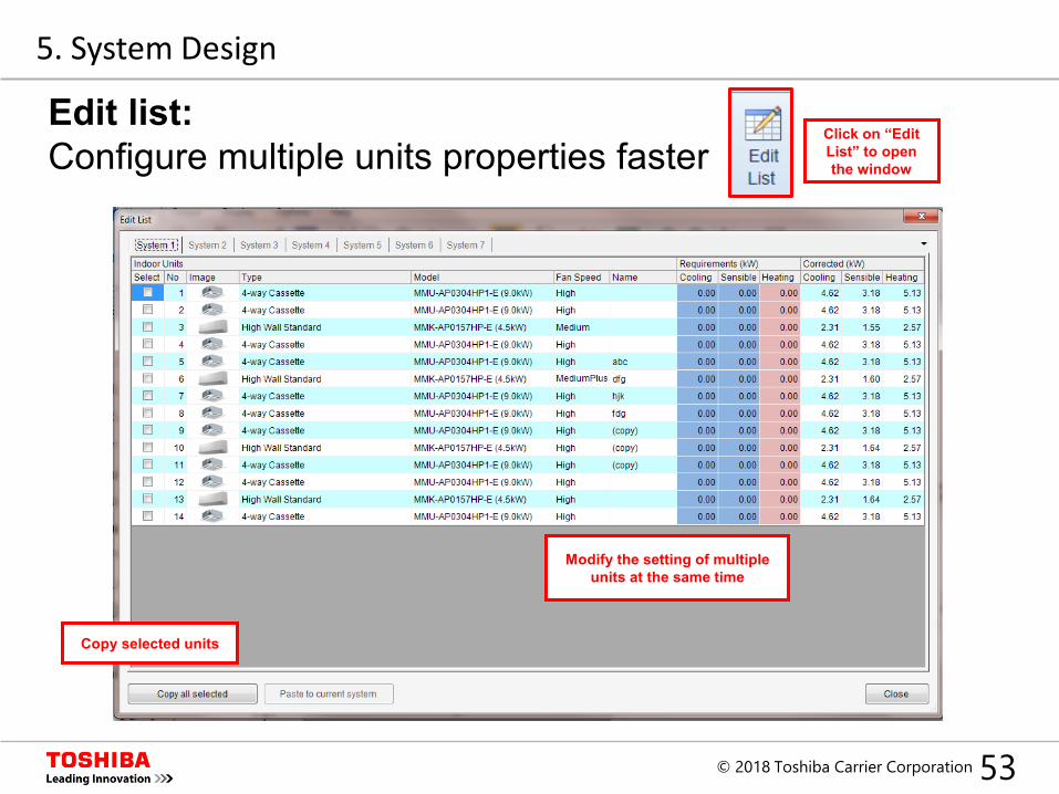
Edit list:Configure multiple units properties faster
Modify the setting of multiple units at the same time
Click on “Edit List” to open the window
Copy selected units
5. System Design
54© 2018 Toshiba Carrier Corporation
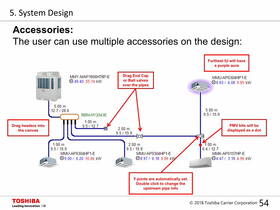
Accessories:The user can use multiple accessories on the design:
Drag End Cap or Ball valves over the pipes
Drag headers into the canvas
Y-joints are automatically set. Double click to change the
upstream pipe info
PMV kits will be displayed as a dot
Furthest IU will have a purple aura
5. System Design
55© 2018 Toshiba Carrier Corporation
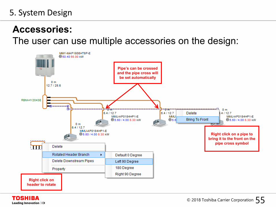
Accessories:The user can use multiple accessories on the design:
Pipe’s can be crossed and the pipe cross will
be set automatically
Right click on header to rotate
Right click on a pipe to bring it to the front on the
pipe cross symbol
5. System Design
56© 2018 Toshiba Carrier Corporation
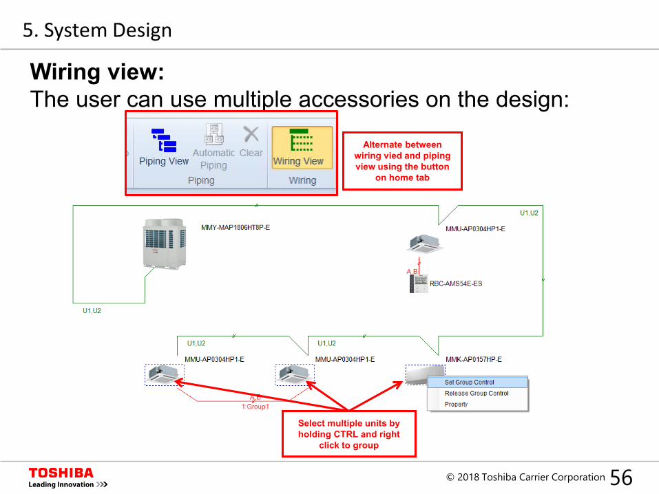
Wiring view:The user can use multiple accessories on the design:
Alternate betweenwiring vied and piping view using the button
on home tab
Select multiple units by holding CTRL and right
click to group
5. System Design
57© 2018 Toshiba Carrier Corporation
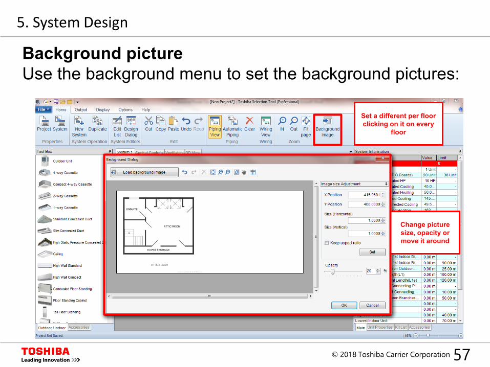
Background pictureUse the background menu to set the background pictures:
Set a different per floor clicking on it on every
floor
5. System Design
Change picture size, opacity or move it around
58© 2018 Toshiba Carrier Corporation
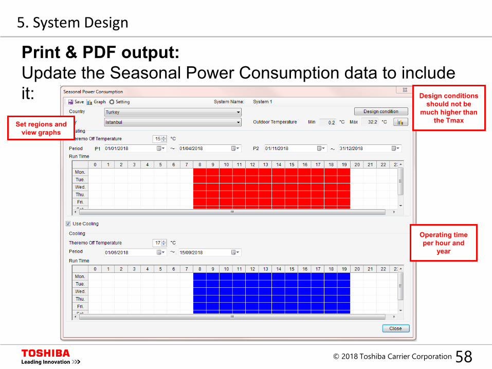
Print & PDF output:Update the Seasonal Power Consumption data to include it:
Operating time per hour and
year
Set regions and view graphs
5. System Design
Design conditions should not be
much higher than the Tmax
59© 2018 Toshiba Carrier Corporation
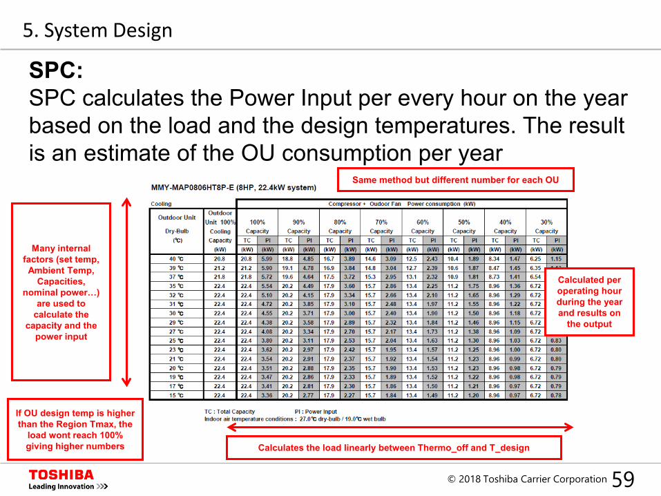
SPC:SPC calculates the Power Input per every hour on the year based on the load and the design temperatures. The result is an estimate of the OU consumption per year
Calculated per operating hour during the year and results on
the output
Same method but different number for each OU
5. System Design
If OU design temp is higher than the Region Tmax, the
load wont reach 100% giving higher numbers Calculates the load linearly between Thermo_off and T_design
Many internal factors (set temp, Ambient Temp,
Capacities, nominal power…)
are used to calculate the
capacity and the power input
60© 2018 Toshiba Carrier Corporation
Index
1. Introduction
2. Set up
3. New Project
4. Design Window
5. System Design
6. Central Controllers
7. Output
61© 2018 Toshiba Carrier Corporation
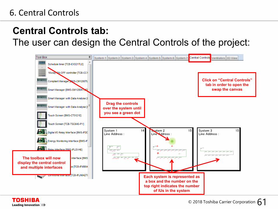
Central Controls tab:The user can design the Central Controls of the project:
Click on “Central Controls” tab in order to open the
swap the canvas
Each system is represented as a box and the number on the
top right indicates the number of IUs in the system
The toolbox will now display the central control
and multiple interfaces
Drag the controls over the system until you see a green dot
6. Central Controls
62© 2018 Toshiba Carrier Corporation
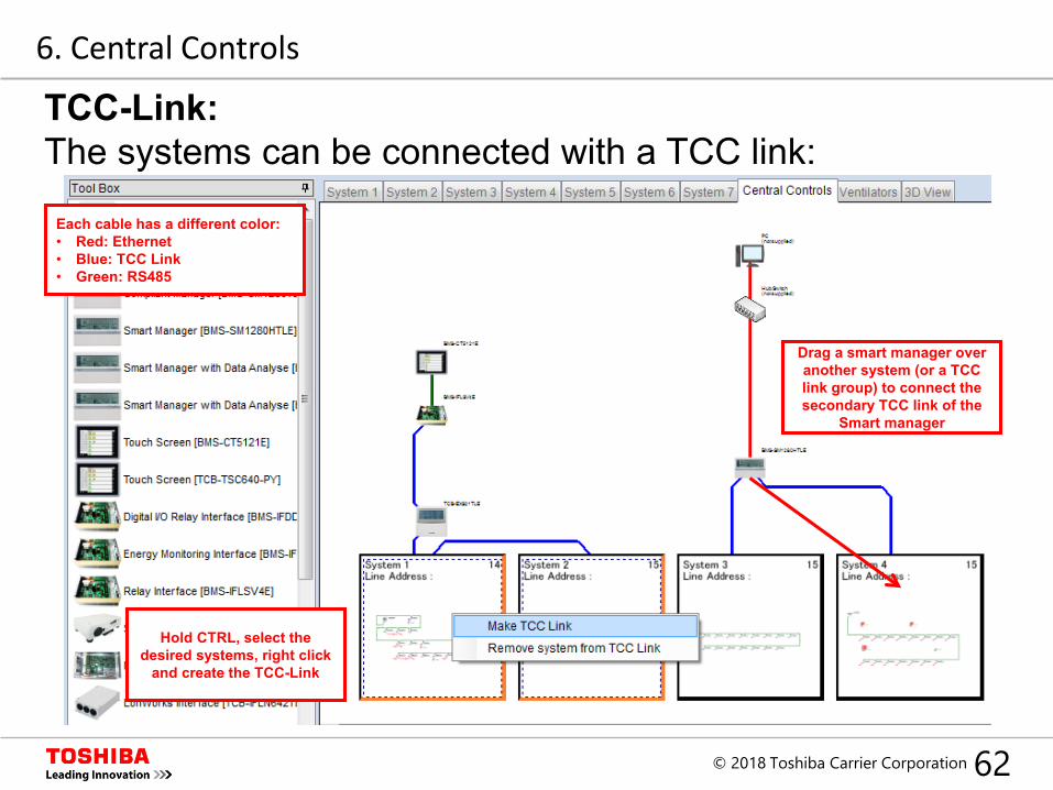
TCC-Link:The systems can be connected with a TCC link:
Drag a smart manager over another system (or a TCC link group) to connect the secondary TCC link of the
Smart manager
Hold CTRL, select the desired systems, right click
and create the TCC-Link
Each cable has a different color:• Red: Ethernet• Blue: TCC Link• Green: RS485
6. Central Controls
63© 2018 Toshiba Carrier Corporation
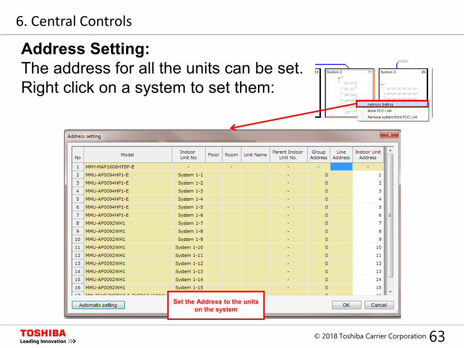
Address Setting:The address for all the units can be set. Right click on a system to set them:
Set the Address to the units on the system
6. Central Controls
64© 2018 Toshiba Carrier Corporation
Index
1. Introduction
2. Set up
3. New Project
4. Design Window
5. System Design
6. Central Controllers
7. Output
65© 2018 Toshiba Carrier Corporation
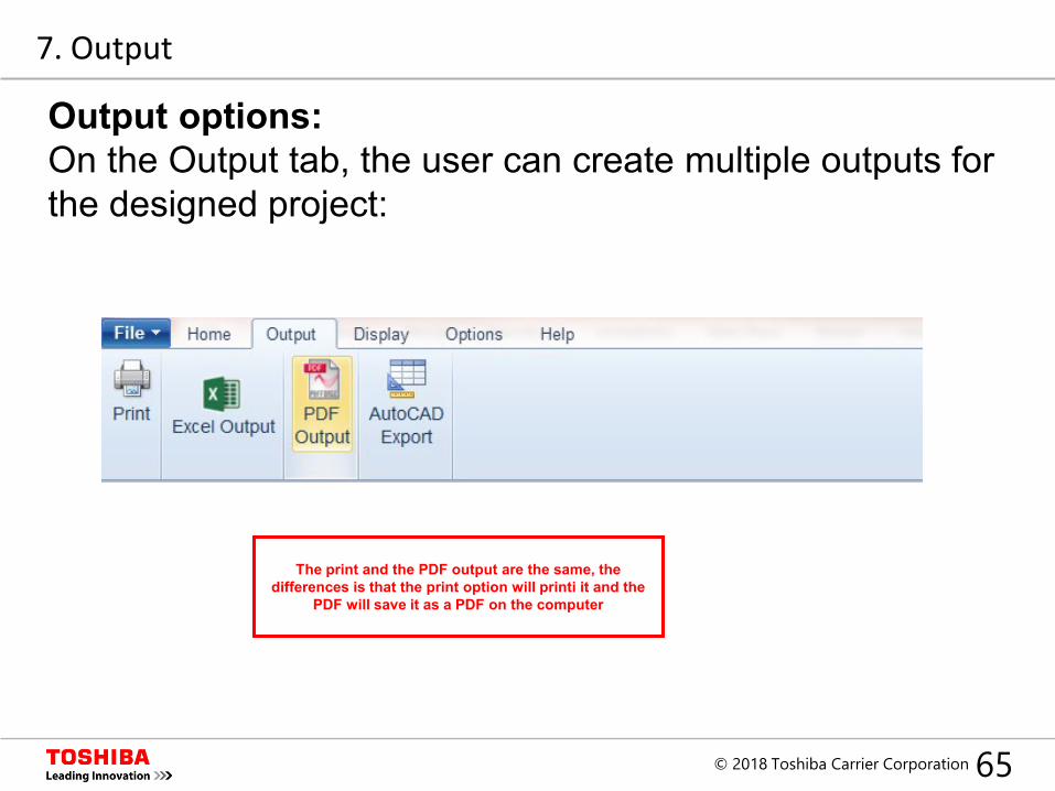
Output options:On the Output tab, the user can create multiple outputs for the designed project:
The print and the PDF output are the same, the differences is that the print option will printi it and the
PDF will save it as a PDF on the computer
7. Output
66© 2018 Toshiba Carrier Corporation
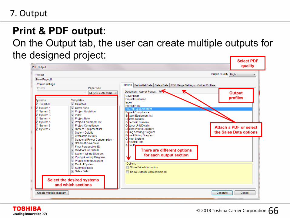
Print & PDF output:On the Output tab, the user can create multiple outputs for the designed project:
Output profiles
Attach a PDF or select the Sales Data options
There are different options for each output section
Select the desired systems and which sections
7. Output
Select PDFquality
67© 2018 Toshiba Carrier Corporation
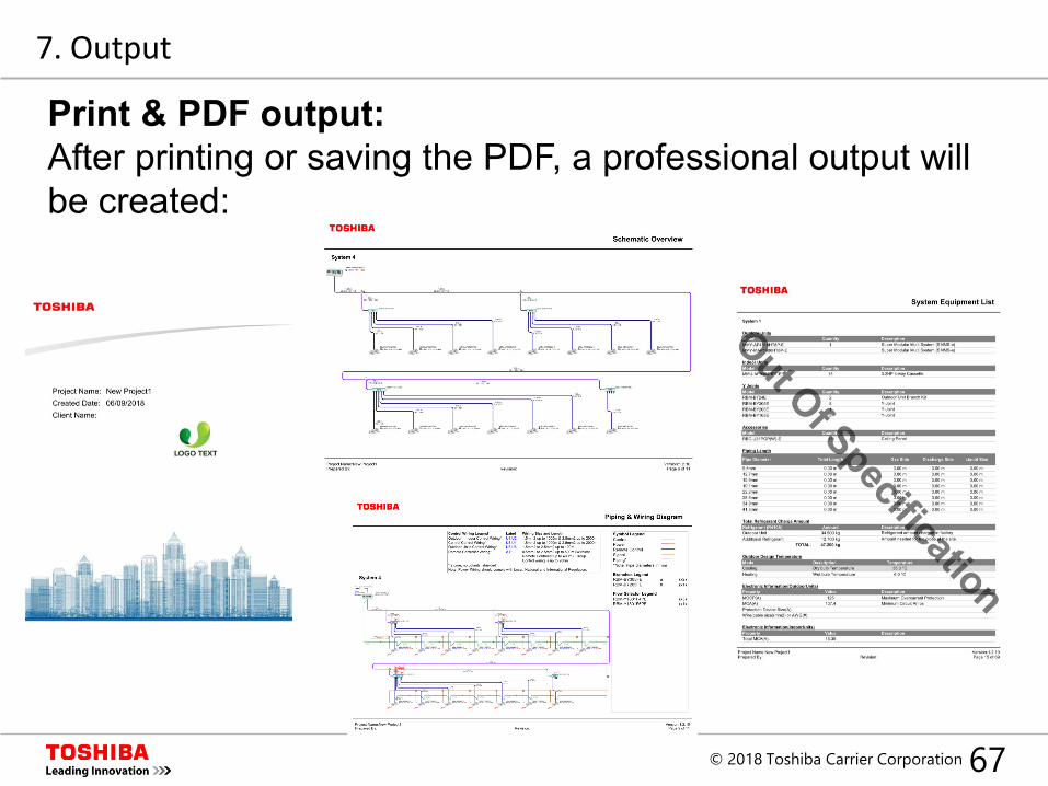
Print & PDF output:After printing or saving the PDF, a professional output will be created:
7. Output
68© 2018 Toshiba Carrier Corporation
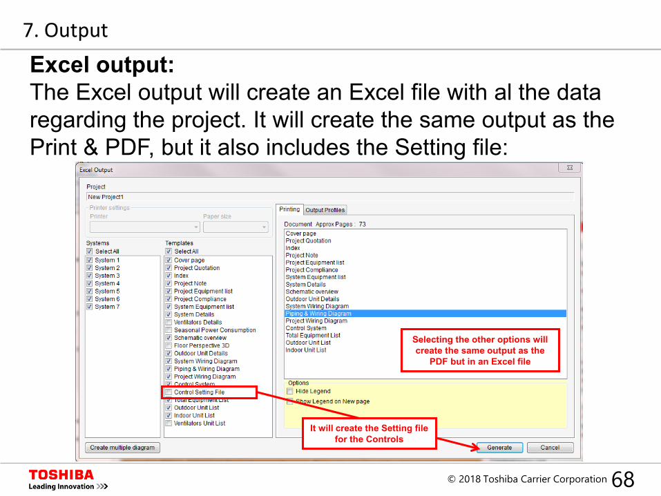
Excel output:The Excel output will create an Excel file with al the data regarding the project. It will create the same output as the Print & PDF, but it also includes the Setting file:
Selecting the other options will create the same output as the
PDF but in an Excel file
It will create the Setting file for the Controls
7. Output
69© 2018 Toshiba Carrier Corporation
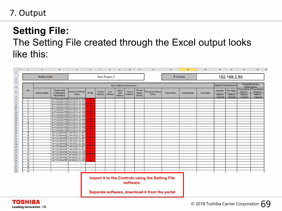
Setting File:The Setting File created through the Excel output looks like this:
Import it to the Controls using the Setting File software.
Separate software, download it from the portal
7. Output
70© 2018 Toshiba Carrier Corporation
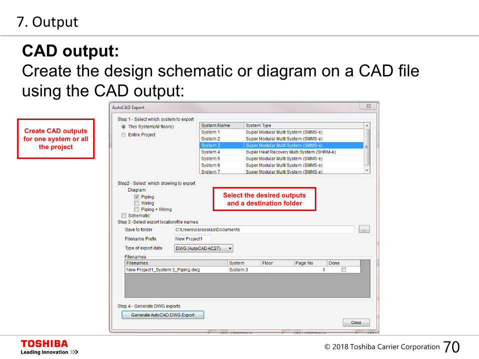
CAD output:Create the design schematic or diagram on a CAD file using the CAD output:
Create CAD outputs for one system or all
the project
Select the desired outputs and a destination folder
7. Output
71© 2018 Toshiba Carrier Corporation
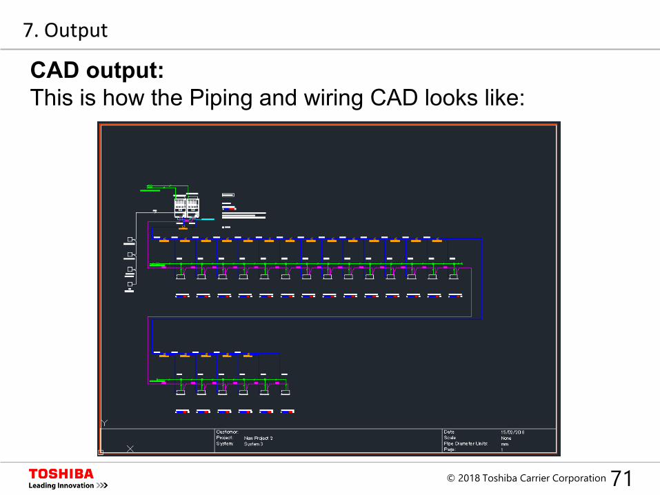
CAD output:This is how the Piping and wiring CAD looks like:
7. Output
72© 2018 Toshiba Carrier Corporation
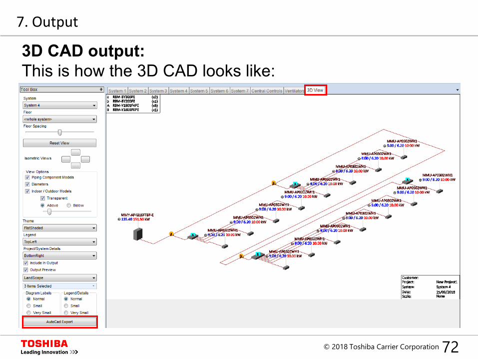
3D CAD output:This is how the 3D CAD looks like:
7. Output