vs-606v7/vs mini j7 memobus instruction...
TRANSCRIPT

YASKAWA VS-606V7/VS mini J7 MEMOBUS INSTRUCTION MANUAL VS-606V7 Series (All Models)
VS mini J7 Series (All Models) (Corresponding to optional units)
YASKAWA ELECTRIC CORPORATION
2
CONTENTS Page
1. INTRODUCTION..................................................................................3
2. CONTROL CIRCUIT TERMINAL ARRANGEMENT AND WIRING ..........5
3. CONSTANTS RELATED TO COMMUNICATIONS .................................6
4. OPERATION WHILE WAITING FOR COMMUNICATIONS AND
AT ERRONEOUS COMMUNICATIONS................................................9
4.1 OPERATION WHILE WAITING FOR COMMUNICATIONS ................ 9
4.2 OPERATION AT ERRONEOUS COMMUNICATIONS........................ 9
5. PROCEDURE FOR COMMUNICATIONS WITH PLC ...........................10
6. COMMUNICATIONS PROCEDURE.....................................................11
6.1 MESSAGE CONFIGURATION...........................................................11
6.2 SLAVE RESPONSE ...........................................................................13
6.3 REQUIRED TIME FOR COMMUNICATIONS....................................14
7. MESSAGE FORMAT...........................................................................15
7.1 READ OUT HOLDING REGISTER CONTENTS[03H] .....................15
7.2 LOOP BACK TEST [08H] ...................................................................16
7.3 WRITING TO SEVERAL HOLDING REGISTERS[10H]...................16
7.4 CRC-16 CALCULATIONS ..................................................................17
8. SELF-TEST.........................................................................................19
9. LIST OF HOLDING REGISTER NUMBERS .........................................20
9.1 REFERENCE DATA (AVAILABLE FOR READ-OUT AND
WRITE-IN)...................................................................................20
9.2 MONITOR DATA (AVAILABLE ONLY FOR READ-OUT).................22
9.3 CONSTANT DATA (AVAILABLE FOR READ-OUT AND
WRITE-IN)....................................................................................25
9.4 ENTER COMMAND (AVAILABLE ONLY FOR WRITE-IN) ..............25
10. ERROR CODES................................................................................26
11. DIGITAL OPERATOR DISPLAY.........................................................27

1. INTRODUCTION Serial communication is available with VS-606V7 (hereinafter called V7) and VS mini J7* series (hereinafter called J7) using programmable controller (PLC) and MEMOBUS protocol. This instruction manual describes only MEMOBUS. For details of the inverter unit operation, refer to the VS-606V7 Series INSTRUCTION MANUAL (Manual No.: TOE-S606-11) or the VS mini J7 Series INSTRUCTION MANUAL (Manual No.: TOE-S606-12). Configuration of MEMOBUS (MODBUS) Communications
MEMOBUS system is composed of a single master (PLC) and slaves (1 to 31 inverter units) Communication between master and slave is controlled according to the master program with the master initiating communication and the slave responding. Basically, the master can send a command only to one slave except at simultaneous broadcasting. Even if several slaves are connected, the master selects the slave to send a command by specifying the pre-registered address No. (slave address) and sends the command to it. The slave receives the communication to carry out designated functions and responds to the master.
Typical Connection of RS-485
VS-606V7
MEMOCON Series Touch Panel
RUN ALARM
RUN ALARM
RUN ALARM
VS-606V7 VS-606V7
* VS mini J7 series can perform MEMOBUS by mounting the optional unit
(model: SI-485/J7).
3

4
Communications Specifications Interface RS-422, RS-485 Synchronization Asynchronous (Start-stop synchronization) Communication parameters
Baud rate: Selected from 2400/4800/9600/19200 bps Data length: 8 bits fixed Parity: Selected from even/odd/none Stop bits: 1 bit fixed
Communication protocol MEMOBUS (MODBUS) (RTU mode only) Max. number of inverters that can be connected
31 units (When using RS-485)

2. CONTROL CIRCUIT TERMINAL ARRANGEMENT AND WIRING V7 Control Circuit Terminal Arrangement
5
FSR- R+P2 P1 S7S6 S5 FR FC AMS- S+PC SC S4 S3 S2 AC RPS1
Connect the shielded cable to the ground at the inverter side.
J7 Optional Communication Unit SI-485/J7 Terminal Arrangement J7 Control Circuit Terminal Arrangement
S- S+ SG R+R- ACAMS1 S2 S3 S4 S5 SC FS FR FC
Connection Example) When RS-422A (4-wire Type) is Used
Connect the shielded cable to the ground at the inverter side.
R- R+
S- S+
S-S+
R-R+
Master Slave 1
PLC
S-S+
R-R+
Slave 31
V7/J7*
V7/J7*
Terminal resistor When communication is carried out byRS-422 or RS-485, turn ON the terminalresistor at the END station viewed fromthe PLC. When V7 is Used (Upper Part of Control Circuit Terminal)
When J7 is Used [Front Panel of Optional Unit (SI-485/J7)]
OFF ON SW2
OFF l
OFF l
At shipment
When terminal resistor ON
When Terminal Resistor is ON
Connection Example) When RS-485 (2-wire Type) is Used
R- R+
S- S+
S-S+
R-R+
Master Slave
VS-606V7/J7* PLC
*When J7 is used on the MEMOBUS, mount the optional unit model SI-485/J7 (separatelyavailable) on the J7 inverter unit.
Precautions on Wiring (1) Separate the wiring for communication from the main circuit wiring or other power
lines. (2) Use shielded cables for communication wiring; connect the shielded sheath to the
ground terminal and terminate the other end to prevent it from being connected.
6
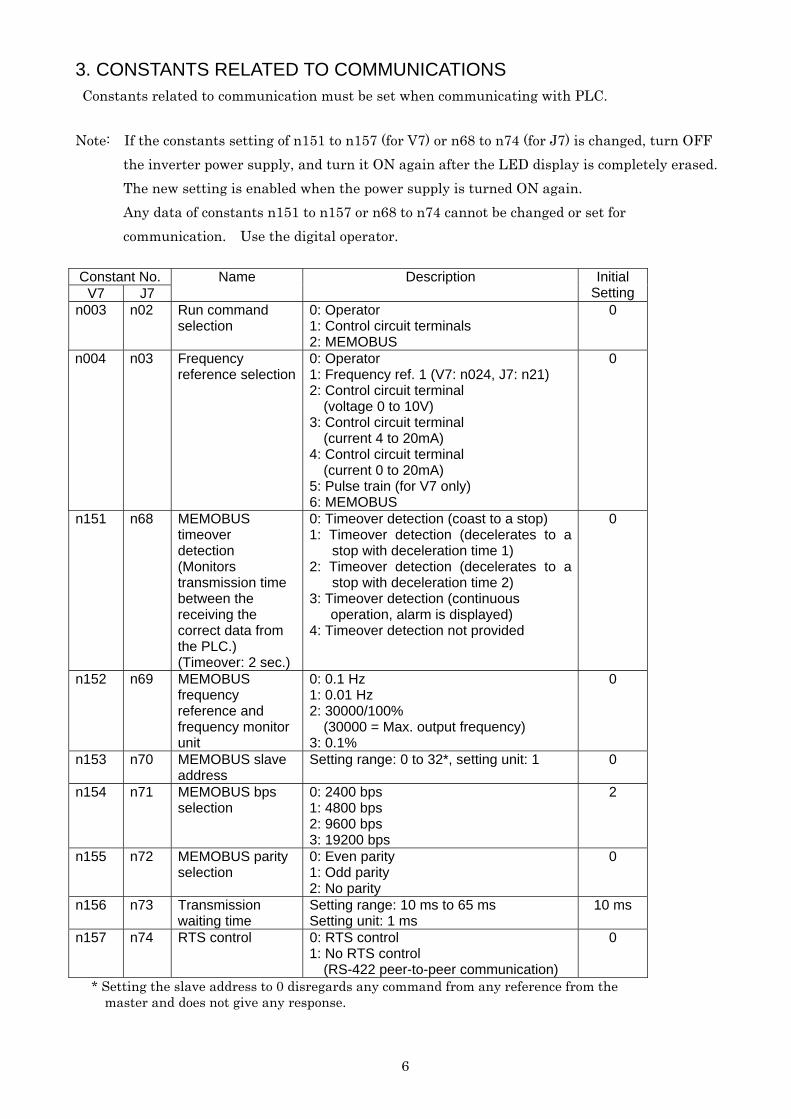
3. CONSTANTS RELATED TO COMMUNICATIONS Constants related to communication must be set when communicating with PLC.
Note: If the constants setting of n151 to n157 (for V7) or n68 to n74 (for J7) is changed, turn OFF the inverter power supply, and turn it ON again after the LED display is completely erased. The new setting is enabled when the power supply is turned ON again. Any data of constants n151 to n157 or n68 to n74 cannot be changed or set for communication. Use the digital operator.
Constant No.
V7 J7 Name Description Initial
Setting n003 n02 Run command
selection 0: Operator 1: Control circuit terminals 2: MEMOBUS
0
n004 n03 Frequency reference selection
0: Operator 1: Frequency ref. 1 (V7: n024, J7: n21) 2: Control circuit terminal (voltage 0 to 10V) 3: Control circuit terminal (current 4 to 20mA) 4: Control circuit terminal (current 0 to 20mA) 5: Pulse train (for V7 only) 6: MEMOBUS
0
n151 n68 MEMOBUS timeover detection (Monitors transmission time between the receiving the correct data from the PLC.) (Timeover: 2 sec.)
0: Timeover detection (coast to a stop) 1: Timeover detection (decelerates to a
stop with deceleration time 1) 2: Timeover detection (decelerates to a
stop with deceleration time 2) 3: Timeover detection (continuous operation, alarm is displayed) 4: Timeover detection not provided
0
n152 n69 MEMOBUS frequency reference and frequency monitor unit
0: 0.1 Hz 1: 0.01 Hz 2: 30000/100% (30000 = Max. output frequency) 3: 0.1%
0
n153 n70 MEMOBUS slave address
Setting range: 0 to 32*, setting unit: 1 0
n154 n71 MEMOBUS bps selection
0: 2400 bps 1: 4800 bps 2: 9600 bps 3: 19200 bps
2
n155 n72 MEMOBUS parity selection
0: Even parity 1: Odd parity 2: No parity
0
n156 n73 Transmission waiting time
Setting range: 10 ms to 65 ms Setting unit: 1 ms
10 ms
n157 n74 RTS control 0: RTS control 1: No RTS control (RS-422 peer-to-peer communication)
0
* Setting the slave address to 0 disregards any command from any reference from the master and does not give any response.
7
Monitoring run status from the PLC, setting/referencing of constants, fault reset and multi-function input reference can be performed regardless of run command or frequency reference selection. Multi-function input reference from PLC becomes OR with input commands from S1 to S7 (J7: S2 to S5) multi-function input terminals. Run command selection (V7: n003, J7: n02)
Selects how to input a run command. Run status monitoring from PLC, constant setting/referencing, fault reset and multi-function input reference are valid regardless of the selection. Multi-function input reference from PLC becomes OR with input commands from the control circuit terminal. Frequency reference selection (V7: n004, J7: n03)
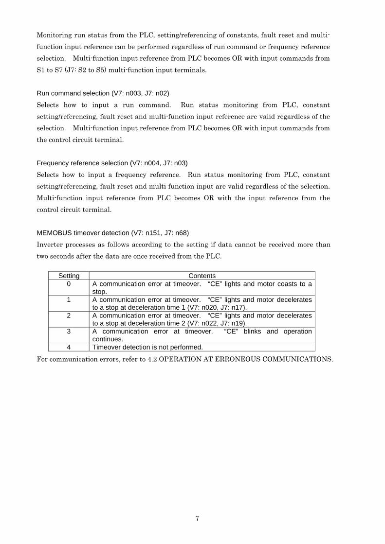
Selects how to input a frequency reference. Run status monitoring from PLC, constant setting/referencing, fault reset and multi-function input are valid regardless of the selection. Multi-function input reference from PLC becomes OR with the input reference from the control circuit terminal. MEMOBUS timeover detection (V7: n151, J7: n68)
Inverter processes as follows according to the setting if data cannot be received more than two seconds after the data are once received from the PLC.
Setting Contents 0 A communication error at timeover. “CE” lights and motor coasts to a
stop. 1 A communication error at timeover. “CE” lights and motor decelerates
to a stop at deceleration time 1 (V7: n020, J7: n17). 2 A communication error at timeover. “CE” lights and motor decelerates
to a stop at deceleration time 2 (V7: n022, J7: n19). 3 A communication error at timeover. “CE” blinks and operation
continues. 4 Timeover detection is not performed.
For communication errors, refer to 4.2 OPERATION AT ERRONEOUS COMMUNICATIONS.

8
MEMOBUS frequency reference and frequency monitor unit (V7: n152, J7: n69)
Selects the frequency reference from PLC, frequency reference monitor by communication, and frequency unit by output frequency monitor. V7 and J7 output frequency calculation resolution is 0.01 Hz. When 30000/100% or 0.1% unit is selected, V7 and J7 convert the received frequency reference into the units of 0.01 Hz and round off the value of the digit below 0.001 Hz. Therefore, some frequency reference values may not coincide with the output frequencies. The following shows the display units for digital operator frequency monitor (FREF) and output frequency monitor (FOUT).
V7 Frequency Unit J7 Frequency Unit Frequency Reference/Monitor
99.99 Hz or less
100.0 Hz or more
99.9 Hz or less
100 Hz or more
Display Unit 0.01 Hz 0.1 Hz 0.1 Hz 1Hz MEMOBUS slave address (V7: n153, J7: n70)
Sets the slave address number. Set the address number which does not overlap any address of other slaves connected on the same communication line. Transmission waiting time (V7: n156, J7: n73)
For details, refer to 6.3 REQUIRED TIME FOR COMMUNICATIONS. RTS control (V7: n157, J7: n74)
Set RTS control to “no RTS control” when RS-422 uses one master and one slave. Set it to “RTS control” when RS-485 or RS-422 has one master and n slaves.
9
4. OPERATION WHILE WAITING FOR COMMUNICATIONS AND AT ERRONEOUS COMMUNICATIONS 4.1 OPERATION WHILE WAITING FOR COMMUNICATIONS
When communication is selected in either the run command selection or the frequency reference selection or in both, and from when the power supply is turned ON to when correct data are received from PLC, the digital operator displays “CAL” (CALL) blinking, indicating that the inverter is waiting for communications. The digital operator also sets the inverter ready signal to 0 (OFF). When normal data are received to the self-station from the PLC, “CAL” stops blinking and being displayed, and the inverter ready signal turns to 1 (ON).
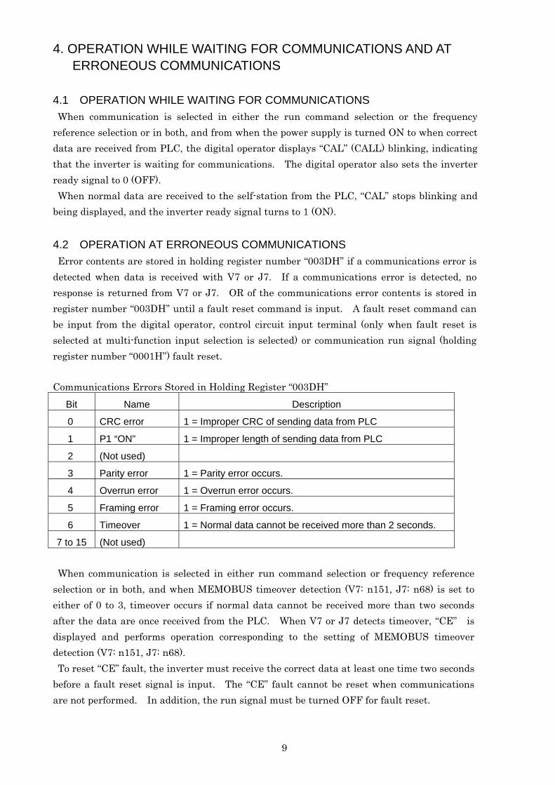
4.2 OPERATION AT ERRONEOUS COMMUNICATIONS Error contents are stored in holding register number “003DH” if a communications error is detected when data is received with V7 or J7. If a communications error is detected, no response is returned from V7 or J7. OR of the communications error contents is stored in register number “003DH” until a fault reset command is input. A fault reset command can be input from the digital operator, control circuit input terminal (only when fault reset is selected at multi-function input selection is selected) or communication run signal (holding register number “0001H”) fault reset.
Communications Errors Stored in Holding Register “003DH” Bit Name Description
0 CRC error 1 = Improper CRC of sending data from PLC
1 P1 “ON” 1 = Improper length of sending data from PLC
2 (Not used)
3 Parity error 1 = Parity error occurs.
4 Overrun error 1 = Overrun error occurs.
5 Framing error 1 = Framing error occurs.
6 Timeover 1 = Normal data cannot be received more than 2 seconds.
7 to 15 (Not used)
When communication is selected in either run command selection or frequency reference selection or in both, and when MEMOBUS timeover detection (V7: n151, J7: n68) is set to either of 0 to 3, timeover occurs if normal data cannot be received more than two seconds after the data are once received from the PLC. When V7 or J7 detects timeover, “CE” is displayed and performs operation corresponding to the setting of MEMOBUS timeover detection (V7: n151, J7: n68). To reset “CE” fault, the inverter must receive the correct data at least one time two seconds before a fault reset signal is input. The “CE” fault cannot be reset when communications are not performed. In addition, the run signal must be turned OFF for fault reset.
10
5. PROCEDURE FOR COMMUNICATIONS WITH PLC The following describes how to do communications with the PLC.
1. Connect the communication cable between the PLC and V7 or J7 after the power supply is turned OFF.
2. Turn the power ON. 3. Set the constants required for communications with MEMOBUS by using the digital
operator. (V7: n151 to n157, J7: n68 to n74) 4. Turn the power OFF once to verify that the operator display is completely erased. 5. Turn ON the power supply again. 6. Communications with the PLC is ready.

6. COMMUNICATIONS PROCEDURE
Communications between the master and the slaves is controlled by the master’s program. In any case, the master sends a command to a slave, and the slave executes the command and responds to the master. The master sends a serial data (command message) in the specified order to the slave, and the slave receives the commands from the master to read and execute them. Then slave sends the data (response message) back to the master.
Holding registers and register numbers
The inverter memory area that can be set or referenced from the master is called holding register. Each holding register has a register number. For data setting/referencing from the master, specify the register number for the starting number of a message. For details of the holding registers, refer to 9 LIST OF HOLDING REGISTER NUMBERS.
6.1 MESSAGE CONFIGURATION
A message is composed of the following four sections: a slave address, a function code, data, and an error check, which must be sent in that
Slave Address Function Code
Data Error Check
Fig. 6.1
order. Fig. 6.1 shows the configuration of a message.
(1) Slave address Number in the range of pre-registered 0 to 32 for each slave. The master communicates with one slave. A command message from the master is received by all the connected slaves, but only the slave whose address coincides with the slave address in the command message can take that command message. On the other hand, the same data (run command, reverse run command, external fault, fault reset, frequency reference) can be set simultaneously for all the connected slaves by setting 0 to the slave address in the command message sent from the master. This is called simultaneous broadcasting. Simultaneous broadcasting cannot be used for reading out holding resisters or a loop back test since a response message is not sent back to the master. The frequency reference unit at simultaneous broadcasting is fixed at 30000/100% disregarding the setting of the constant n152 (V7) or n69 (J7).
11

12
(2) Function code The master specifies the function to be executed by the slave by using a function code.
Table 6.1 describes the function codes Function Code (Hexadecimal)
Function Max. Qty per Message
Remarks
03H Reading holding register contents
16
08H Loop back test - 10H Writing in several holding
registers 16 Simultaneous
broadcasting available
(3) Data Data necessary for the slave to execute the function command. The required data differ depending on the function command. Refer to the description of the message format for each function command.
(4) Error check Data for an error check is sent at the end of the message in order to detect the message error (bit change) when communicating. An error check is carried out by CRC-16 (cyclic redundancy check-16). For details, refer to 7.4 CRC-16 CALCULATIONS.
13
6.2 SLAVE RESPONSE When a slave receives a command message from the master, it performs various checks. If nothing is wrong, the command message in the receiving buffer is moved to the execution buffer. If something is wrong, the command message is disregarded and no procedure is taken. When the received message is correct, the contents of the command message are decoded and executed. After that the slave prepares a response message for the master and transfers it to the sending buffer. If there is an error in the command message (for example, a function code that does not exist is provided, etc.), the slave does not execute the command and prepares a response message indicating the error and transfers it to the sending buffer. When the response message arrives in the sending buffer, it is sent to the master. (1) Response during normal conditions
With the loop back function, the slave returns the same response message as the command message. With the function to write to several holding registers, the slave returns a part of command message (slave address, function code, start number, number of holding registers) as the command message. With read-out function, the slave address and the function code must be the same as the command message and the read out data are added.
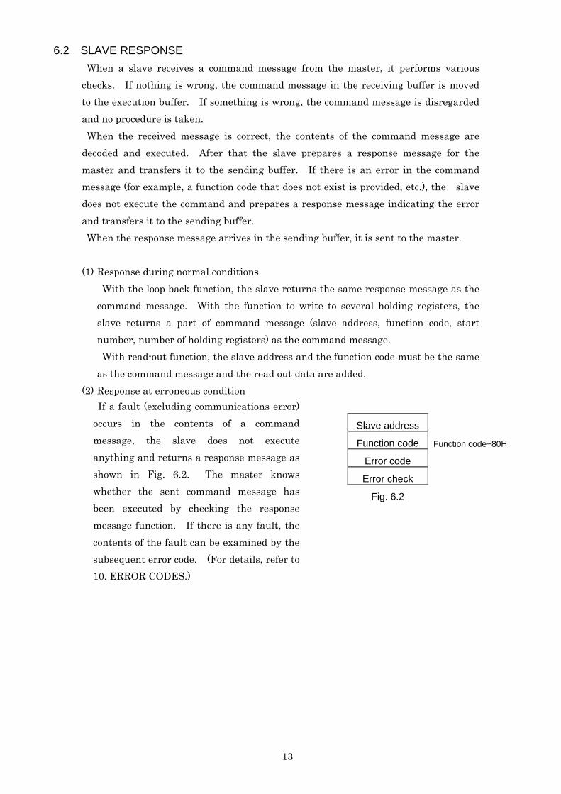
(2) Response at erroneous condition
Slave address Function code Function code+80H
Error code Error check Fig. 6.2
If a fault (excluding communications error) occurs in the contents of a command message, the slave does not execute anything and returns a response message as shown in Fig. 6.2. The master knows whether the sent command message has been executed by checking the response message function. If there is any fault, the contents of the fault can be examined by the subsequent error code. (For details, refer to 10. ERROR CODES.)
(3) No response The slave disregards the command message and does not respond in the following cases. If the slave address in the command message is “0” at the write-in function, all slaves execute the command but do not return any response. - A communications error (one of the following: overrun, framing, parity or CRC-16) is detected in the command message. - The slave address in the command message does not coincide with the slave address (V7: n153, J7: n70) set in the slave. - The interval between the data composing the message exceeds 24 bits. - The data length of the command message is improper.
Note: Provide a timer for the master to monitor the response so that the same command message will be sent again if no response is returned within the time.
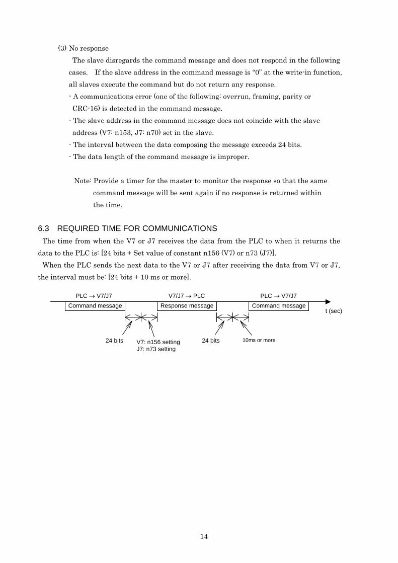
6.3 REQUIRED TIME FOR COMMUNICATIONS
The time from when the V7 or J7 receives the data from the PLC to when it returns the data to the PLC is: [24 bits + Set value of constant n156 (V7) or n73 (J7)].
When the PLC sends the next data to the V7 or J7 after receiving the data from V7 or J7, the interval must be: [24 bits + 10 ms or more].
Command message Response message Command message
24 bits V7: n156 setting J7: n73 setting
24 bits 10ms or more
t (sec)
PLC → V7/J7 V7/J7 → PLC PLC → V7/J7
14

15
7. MESSAGE FORMAT A message format is shown in Fig. 6.1. The data length (quantity) and the contents differ depending on the functions. Table 7.1 shows the message length for each function.
Note: Communication error occurs if the data continues after CRC-16 (lower digit), do not add
any data after CRC-16. Table 7.1
Command message Response Message Function Code (Hexadecimal)
Function Minimum
(Byte) Maximum
(Byte) Minimum
(Byte) Maximum
(Byte) 03H Reading holding
resistor contents 8 8 7 37
08H Loop back test 8 8 8 8 10H Write in several
holding resistors 11 41 8 8
7.1 READ OUT HOLDING REGISTER CONTENTS [03H] Reads out the contents of the holding registers with the continuous numbers for the
specified quantity. The contents of holding registers are divided into the upper 8 bits and the lower 8 bits. They become the data items in response message in the order of numbers.
(Example) Reads out status signal, fault contents, data link status and frequency reference from the slave 2 V7 or J7. Response message Command Message
Command Message (at Normal Operation) (at Faulty Operation) Slave address 02H Slave address 02H Slave address 02H Function code 03H Function code 03H Function code 83H
Upper 00H Number of data 08H Error code 03H Start No. Lower 20H Upper 00H Upper F1H Upper 00H
First holding register Lower 65H CRC-16 Lower 31H Quantity* Lower 04H Upper 00H
Upper 45H Next holding
register Lower 00H CRC-16 Lower F0H Upper 00H
Next holding register Lower 00H
Upper 01H
Next holding register Lower F4H
Upper AFH CRC-16 Lower 82H
*: If the quantity is 0 or exceeds 16, error code “03H” is returned.

16
7.2 LOOP BACK TEST [08H] Command message is returned as a response message without being changed. This
function is used to check communication between the master and the slave. Any arbitrary values can be used for test codes or data.
(Example) Loop-back test of slave 1 V7 or J7
Response Message Command Message Command Message (at Normal Operation) (at Faulty Operation)
Slave address 01H Slave address 01H Slave address 01H Function code 08H Function code 08H Function code 88H
Upper 00H Upper 00H Error code 01H Test code Lower 00H Test code Lower 00H Upper 86H Upper A5H Upper A5H CRC-16 Lower 50H Data Lower 37H Data Lower 37H Upper DAH Upper DAH CRC-16 Lower 8DH CRC-16 Lower 8DH
7.3 WRITING TO SEVERAL HOLDING REGISTERS [10H] Specified data are written into the several specified holding registers from the specified number, respectively. Written data must be arranged in a command message in the order of holding register numbers; from upper eight bits to lower eight bits. (Example) Set forward run at frequency reference 60.0 Hz to slave 1 V7 or J7 from the PLC.
Response Message Command Message Command Message (at Normal Operation) (at Fault Operation)
Slave address *1 01H Slave address 01H Slave address 01H Function code 10H Function code 10H Function code 90H
Upper 00H Upper 00H Error code 02HStart No. Lower 01H Start No. Lower 01H Upper CDHUpper 00H Upper 00H CRC-16 Lower C1HQuantity *2 Lower 02H Quantity Lower 02H
Number of data *2 04H Upper 10H Upper 00H CRC-16 Lower 08H First data Lower 01H Upper 02H Next data Lower 58H Upper 63H CRC-16 Lower 39H
*1: Setting the slave address to “00H”, all the slaves execute this command. However, no slave
respond after execution. *2: If the quantity is 0 or exceeds 16, or if the number of data is not [quantity × 2], error code “03H” is
returned.
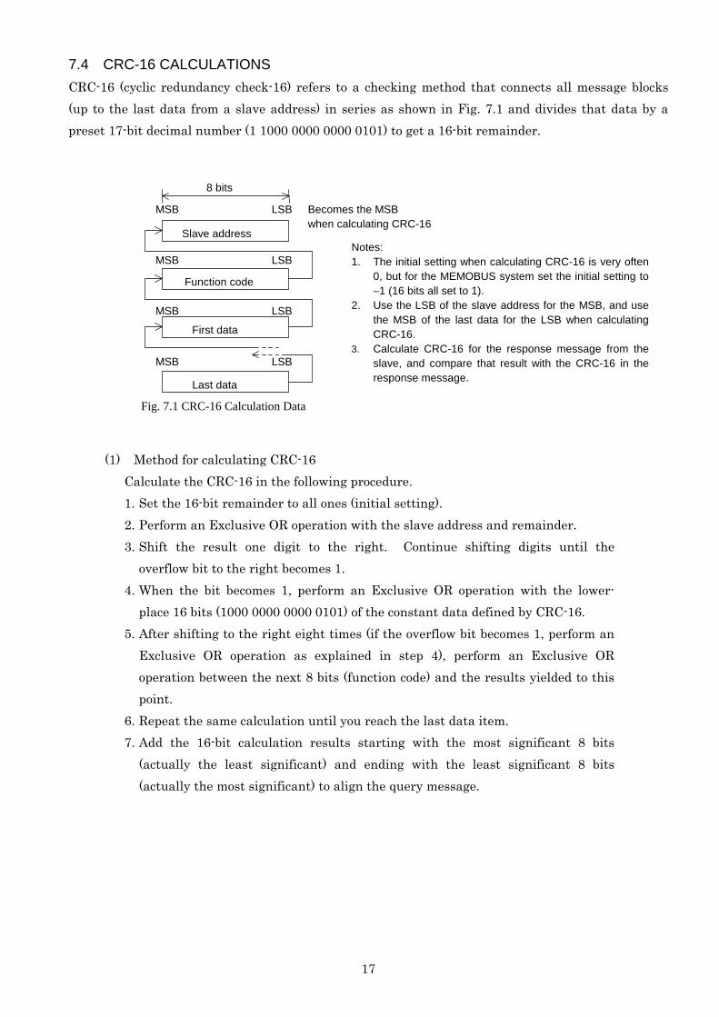
7.4 CRC-16 CALCULATIONS CRC-16 (cyclic redundancy check-16) refers to a checking method that connects all message blocks (up to the last data from a slave address) in series as shown in Fig. 7.1 and divides that data by a preset 17-bit decimal number (1 1000 0000 0000 0101) to get a 16-bit remainder.
Slave address
MSB
MSB
MSB
MSB
LSB
LSB
LSB
LSB
8 bits
Function code
First data
Last data
Becomes the MSB when calculating CRC-16
Notes: 1. The initial setting when calculating CRC-16 is very often
0, but for the MEMOBUS system set the initial setting to –1 (16 bits all set to 1).
2. Use the LSB of the slave address for the MSB, and use the MSB of the last data for the LSB when calculating CRC-16.
3. Calculate CRC-16 for the response message from the slave, and compare that result with the CRC-16 in the response message.
Fig. 7.1 CRC-16 Calculation Data
(1) Method for calculating CRC-16 Calculate the CRC-16 in the following procedure. 1. Set the 16-bit remainder to all ones (initial setting). 2. Perform an Exclusive OR operation with the slave address and remainder. 3. Shift the result one digit to the right. Continue shifting digits until the
overflow bit to the right becomes 1. 4. When the bit becomes 1, perform an Exclusive OR operation with the lower-
place 16 bits (1000 0000 0000 0101) of the constant data defined by CRC-16. 5. After shifting to the right eight times (if the overflow bit becomes 1, perform an
Exclusive OR operation as explained in step 4), perform an Exclusive OR operation between the next 8 bits (function code) and the results yielded to this point.
6. Repeat the same calculation until you reach the last data item. 7. Add the 16-bit calculation results starting with the most significant 8 bits
(actually the least significant) and ending with the least significant 8 bits (actually the most significant) to align the query message.
17
18
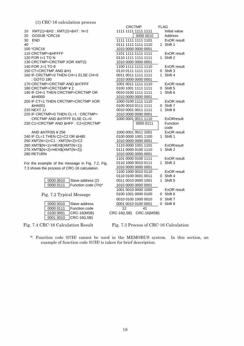
(1) CRC-16 calculation process CRCTMP FLAG 10 XMT(1)=&H2 : XMT(2)=&H7 : N=2 1111 1111 1111 1111 Initial value 20 GOSUB *CRC16 0000 0010 Address 30 END 1111 1111 1111 1101 ExOR result 40 ' 0111 1111 1111 1110 1 Shift 1 100 *CRC16 1010 0000 0000 0001 110 CRCTMP=&HFFFF 1101 1111 1111 1111 ExOR result 120 FOR I=1 TO N 0110 1111 1111 1111 1 Shift 2 130 CRCTMP=CRCTMP XOR XMT(I) 1010 0000 0000 0001 140 FOR J=1 TO 8 1100 1111 1111 1110 ExOR result 150 CT=CRCTMP AND &H1 0110 0111 1111 1111 0 Shift 3 160 IF CRCTMP<0 THEN CH=1 ELSE CH=0 0011 0011 1111 1111 1 Shift 4 : GOTO 180 1010 0000 0000 0001 170 CRCTMP=CRCTMP AND &H7FFF 1001 0011 1111 1110 ExOR result 180 CRCTMP=CRCTEMP ¥ 2 0100 1001 1111 1111 0 Shift 5 190 IF CH=1 THEN CRCTMP=CRCTMP OR 0010 0100 1111 1111 1 Shift 6 &H4000 1010 0000 0000 0001 200 IF CT=1 THEN CRCTMP=CRCTMP XOR 1000 0100 1111 1110 ExOR result &HA001 0100 0010 0111 1111 0 Shift 7 210 NEXT J,I 0010 0001 0011 1111 1 Shift 8 220 IF CRCTMP<0 THEN CL=1 : CRCTMP= 1010 0000 0000 0001 CRCTMP AND &H7FFF ELSE CL=0 1000 0001 0011 1110 ExORresult 230 C1=CRCTMP AND &HFF : C2=(CRCTMP 0000 0111 Function
code AND &H7F00) ¥ 256 1000 0001 0011 1001 ExOR result 240 IF CL=1 THEN C2=C2 OR &H80 0100 0000 1001 1100 1 Shift 1 250 XMT(N+1)=C1 : XMT(N+2)=C2 1010 0000 0000 0001 260 XMT$(N+1)=HEX$(XMT(N+1)) 1110 0000 1001 1101 ExORresult 270 XMT$(N+2)=HEX$(XMT(N+2)) 0111 0000 0100 1110 1 Shift 2 280 RETURN 1010 0000 0000 0001 1101 0000 0100 1111 ExOR result
0110 1000 0010 0111 1 Shift 3 1010 0000 0000 0001
For the example of the message in Fig. 7.2, Fig. 7.3 shows the process of CRC-16 calculation.
1100 1000 0010 0110 ExOR result 0110 0100 0001 0011 0 Shift 4 0000 0010 Slave address (2) 0011 0010 0000 1001 1 Shift 5 0000 0111 Function code (7H)* 1010 0000 0000 0001 1001 0010 0000 1000 ExOR result
Fig. 7.2 Typical Message 0100 1001 0000 0100 0 Shift 6 0010 0100 1000 0010 0 Shift 7 0000 0010 Slave address 0001 0010 0100 0001 0 Shift 8 0000 0111 Function code 12 41 0100 0001 CRC-16(MSB) CRC-16(LSB) CRC-16(MSB) 0001 0010 CRC-16(LSB)
Fig. 7.4 CRC-16 Calculation Result Fig. 7.3 Process of CRC-16 Calculation
*: Function code (07H) cannot be used in the MEMOBUS system. In this section, an example of function code (07H) is taken for brief description.
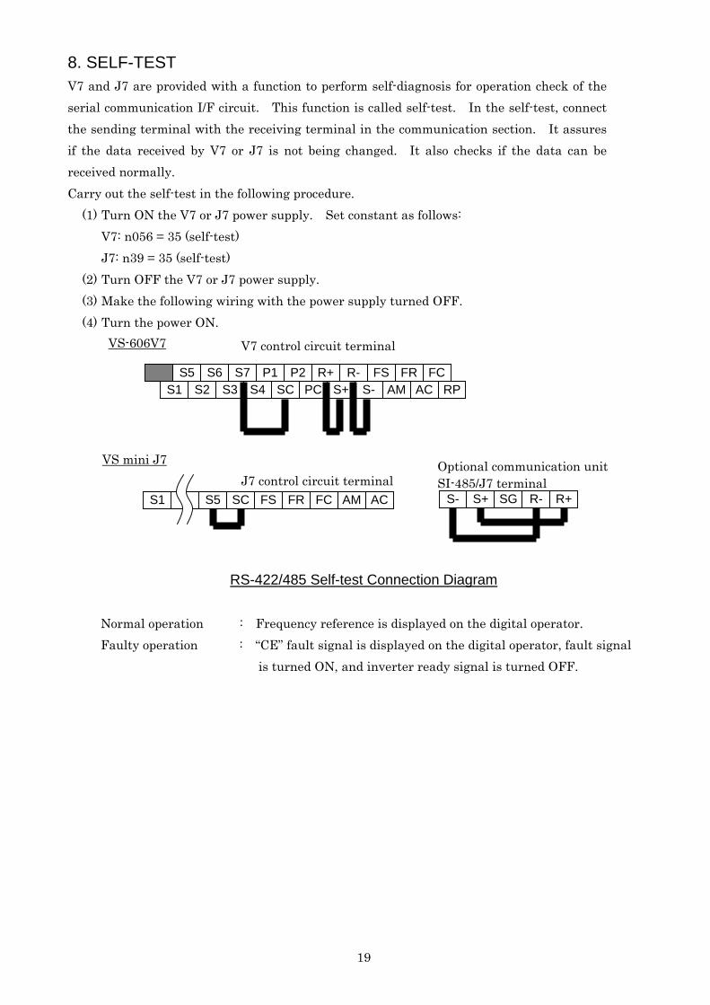
8. SELF-TEST V7 and J7 are provided with a function to perform self-diagnosis for operation check of the serial communication I/F circuit. This function is called self-test. In the self-test, connect the sending terminal with the receiving terminal in the communication section. It assures if the data received by V7 or J7 is not being changed. It also checks if the data can be received normally. Carry out the self-test in the following procedure.
(1) Turn ON the V7 or J7 power supply. Set constant as follows: V7: n056 = 35 (self-test) J7: n39 = 35 (self-test)
(2) Turn OFF the V7 or J7 power supply. (3) Make the following wiring with the power supply turned OFF. (4) Turn the power ON.
19
FSR-R+P2P1 S7 S6 S5 FR FC AMS-S+PCSCS4 S3 S2 AC RPS1
SG S+S- R- R+
VS-606V7
VS mini J7
SI-485/J7 terminal ACAMFCFRFS SC S5 S1
J7 control circuit terminal
V7 control circuit terminal
Optional communication unit
RS-422/485 Self-test Connection Diagram
Normal operation : Frequency reference is displayed on the digital operator. Faulty operation : “CE” fault signal is displayed on the digital operator, fault signal
is turned ON, and inverter ready signal is turned OFF.
20
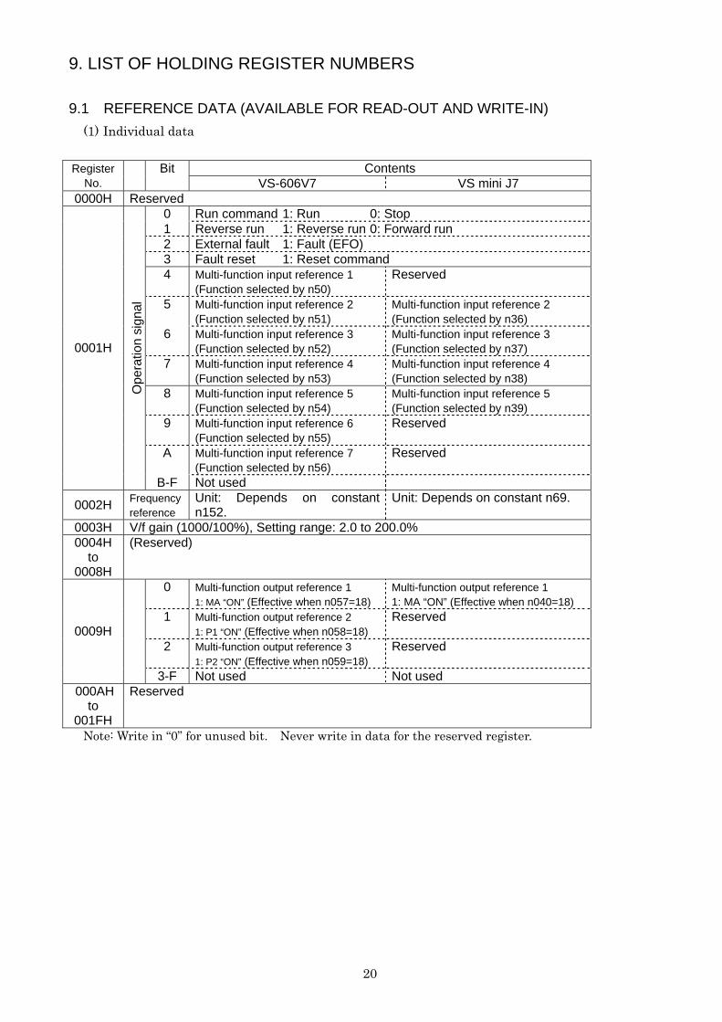
9. LIST OF HOLDING REGISTER NUMBERS 9.1 REFERENCE DATA (AVAILABLE FOR READ-OUT AND WRITE-IN)
(1) Individual data
Contents Register No.
Bit VS-606V7 VS mini J7
0000H Reserved 0 Run command 1: Run 0: Stop 1 Reverse run 1: Reverse run 0: Forward run 2 External fault 1: Fault (EFO) 3 Fault reset 1: Reset command 4 Multi-function input reference 1
(Function selected by n50) Reserved
5 Multi-function input reference 2 (Function selected by n51)
Multi-function input reference 2 (Function selected by n36)
6 Multi-function input reference 3 (Function selected by n52)
Multi-function input reference 3 (Function selected by n37)
7 Multi-function input reference 4 (Function selected by n53)
Multi-function input reference 4 (Function selected by n38)
8 Multi-function input reference 5 (Function selected by n54)
Multi-function input reference 5 (Function selected by n39)
9 Multi-function input reference 6 (Function selected by n55)
Reserved
A Multi-function input reference 7 (Function selected by n56)
Reserved
0001H
Ope
ratio
n si
gnal
B-F Not used
0002H Frequency reference
Unit: Depends on constant n152.
Unit: Depends on constant n69.
0003H V/f gain (1000/100%), Setting range: 2.0 to 200.0% 0004H
to 0008H
(Reserved)
0 Multi-function output reference 1 1: MA “ON” (Effective when n057=18)
Multi-function output reference 1 1: MA “ON” (Effective when n040=18)
1 Multi-function output reference 2 1: P1 “ON” (Effective when n058=18)
Reserved
2 Multi-function output reference 3 1: P2 “ON” (Effective when n059=18)
Reserved 0009H
3-F Not used Not used 000AH
to 001FH
Reserved
Note: Write in “0” for unused bit. Never write in data for the reserved register.
21
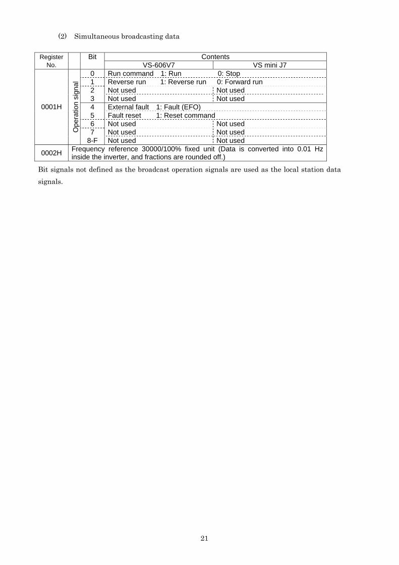
(2) Simultaneous broadcasting data
Contents Register No.
Bit VS-606V7 VS mini J7
0 Run command 1: Run 0: Stop 1 Reverse run 1: Reverse run 0: Forward run 2 Not used Not used 3 Not used Not used 4 External fault 1: Fault (EFO) 5 Fault reset 1: Reset command 6 Not used Not used 7 Not used Not used
0001H
Ope
ratio
n si
gnal
8-F Not used Not used
0002H Frequency reference 30000/100% fixed unit (Data is converted into 0.01 Hz inside the inverter, and fractions are rounded off.)
Bit signals not defined as the broadcast operation signals are used as the local station data signals.
22
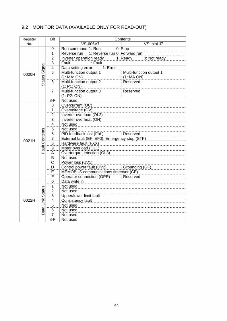
9.2 MONITOR DATA (AVAILABLE ONLY FOR READ-OUT)
Contents Register
No. Bit
VS-606V7 VS mini J7 0 Run command 1: Run 0: Stop 1 Reverse run 1: Reverse run 0: Forward run 2 Inverter operation ready 1: Ready 0: Not ready 3 Fault 1: Fault 4 Data setting error 1: Error 5 Multi-function output 1
(1: MA: ON) Multi-function output 1 (1: MA ON)
6 Multi-function output 2 (1: P1: ON)
Reserved
7 Multi-function output 3 (1: P2: ON)
Reserved
0020H
Sta
tus
Sig
nal
8-F Not used 0 Overcurrent (OC) 1 Overvoltage (OV) 2 Inverter overload (OL2) 3 Inverter overheat (OH) 4 Not used 5 Not used 6 PID feedback lost (FbL) Reserved 7 External fault (EF, EF0), Emergency stop (STP) 8 Hardware fault (FXX) 9 Motor overload (OL1) A Overtorque detection (OL3) B Not used C Power loss (UV1) D Control power fault (UV2) Grounding (GF) E MEMOBUS communications timeover (CE)
0021H
Faul
t Con
tent
s
F Operator connection (OPR) Reserved 0 Data write in 1 Not used 2 Not used 3 Upper/lower limit fault 4 Consistency fault 5 Not used 6 Not used 7 Not used
0022H
Dat
a Li
nk S
tatu
s
8-F Not used

23
Contents Register
No. Bit
VS-606V7 VS mini J7 0023H Frequency
reference (Unit: n152) (Unit: n69)
0024H Output frequency
(Unit: n152) (Unit: n69)
0025H Not used 0026H Not used 0027H Output current (10/1A) 0028H Output voltage reference (1/1V) 0029H Not used 002AH Not used
0 Terminal S1 1: Closed 1 Terminal S2 1: Closed 2 Terminal S3 1: Closed 3 Terminal S4 1: Closed 4 Terminal S5 1: Closed 5 Terminal S6 1: Closed Reserved 6 Terminal S7 1: Closed Reserved
002BH
Con
trol C
ircui
t Te
rmin
al In
put
Sta
tus
7-F Not used 0 Run 1: Run 1 Zero-speed 1: Zero-speed 2 Frequency agreed 1: Agreed 3 Minor fault (Alarm is indicated.) 4 Frequency detection 1
1: Output frequency ≤ (n095) Frequency detection 1 1: Output frequency ≤ (n58)
5 Frequency detection 2 1: Output frequency ≥ (n095)
Frequency detection 2 1: Output frequency ≥ (n58)
6 Inverter operation ready 1: Ready 7 Undervoltage detection 1: Undervoltage detection 8 Baseblock 1: Inverter baseblock detection 9 Frequency reference mode 1: Other than communications
0: Communications A Run command mode 1: Other than communications
0: Communications B Overtorque detection 1: Overtorque detection C Not used D Fault restart E Fault (Including communications timeover) 1: Fault
002CH
Inve
rter S
tatu
s
F Communications timeover 1: Timeover

24
Contents Register
No. Bit
VS-606V7 VS mini J7 0 MA”ON” 1 : Closed MA “ON” 1: Closed 1 P1”ON” 1 : Closed Reserved 2 P2”ON” 1 : Closed Reserved 3 Not used 4 Not used 5 Not used 6 Not used 7 Not used
002DH
Con
trol C
ircui
t Ter
min
al
Out
put S
tatu
s
8-F Not used 002EH
to 0030H
Reserved
0031H Main circuit DC voltage (1/1V)
0032H Torque monitor (1/1%, 100%/motor rated torque, with sign)
Reserved
0033H Not used 0034H Not used 0035H Not used 0036H Not used 0037H Output power (1/1W, with sign) Reserved
0038H PID feedback (100%/input equivalent to maximum output frequency, 10/1%, without sign)
Reserved
0039H PID input (±100%/±maximum output frequency, 10/1%, with sign)
Reserved
003AH PID output (±100%/±maximum output frequency, 10/1%, with sign)
Reserved
003BH Reserved 003CH Reserved
0 CRC error 1 Improper data length 2 Not used 3 Parity error 4 Overrun error 5 Framing error 6 Timeover 7 Not used
003DH*
Con
tent
s of
C
omm
unic
atio
ns E
rror
8-F Not used 003EH
to 00FFH
Reserved
*: The contents of a communications error is held unless a fault reset is input (can be reset during running.)
25
9.3 CONSTANT DATA (AVAILABLE FOR READ-OUT AND WRITE-IN) Refer to “ CONTANTS LIST” of the VS-606V7 or VS mini J7 instruction manual.
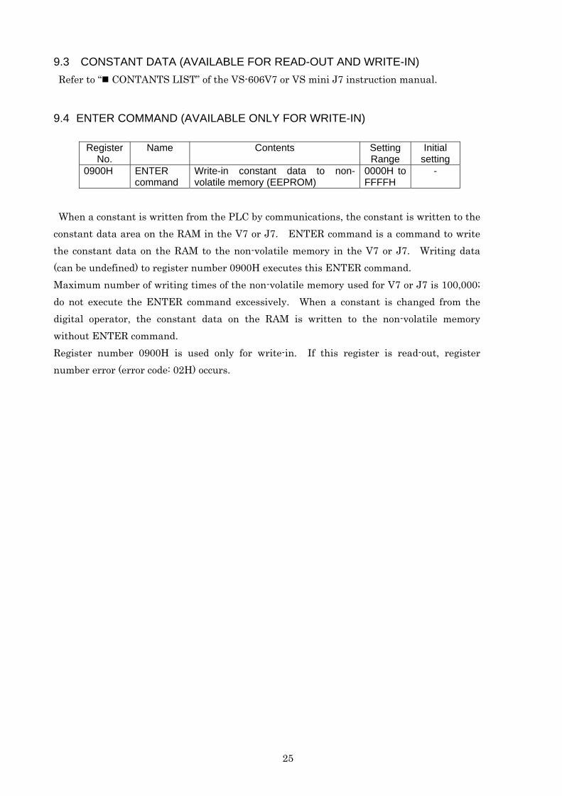
9.4 ENTER COMMAND (AVAILABLE ONLY FOR WRITE-IN)
Register No.
Name Contents Setting Range
Initial setting
0900H ENTER command
Write-in constant data to non-volatile memory (EEPROM)
0000H to FFFFH
-
When a constant is written from the PLC by communications, the constant is written to the constant data area on the RAM in the V7 or J7. ENTER command is a command to write the constant data on the RAM to the non-volatile memory in the V7 or J7. Writing data (can be undefined) to register number 0900H executes this ENTER command. Maximum number of writing times of the non-volatile memory used for V7 or J7 is 100,000; do not execute the ENTER command excessively. When a constant is changed from the digital operator, the constant data on the RAM is written to the non-volatile memory without ENTER command. Register number 0900H is used only for write-in. If this register is read-out, register number error (error code: 02H) occurs.
26
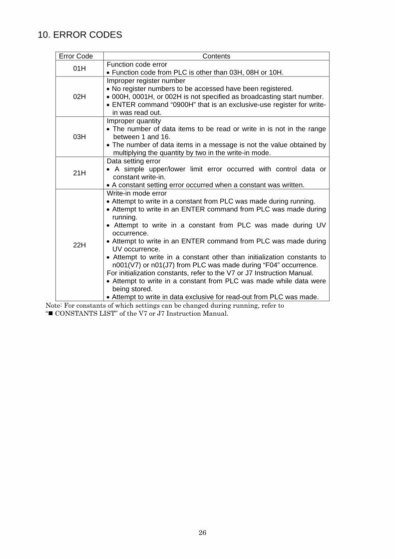
10. ERROR CODES
Error Code Contents
01H Function code error • Function code from PLC is other than 03H, 08H or 10H.
02H
Improper register number • No register numbers to be accessed have been registered. • 000H, 0001H, or 002H is not specified as broadcasting start number. • ENTER command “0900H” that is an exclusive-use register for write-
in was read out.
03H
Improper quantity • The number of data items to be read or write in is not in the range
between 1 and 16. • The number of data items in a message is not the value obtained by
multiplying the quantity by two in the write-in mode.
21H
Data setting error • A simple upper/lower limit error occurred with control data or
constant write-in. • A constant setting error occurred when a constant was written.
22H
Write-in mode error • Attempt to write in a constant from PLC was made during running. • Attempt to write in an ENTER command from PLC was made during
running. • Attempt to write in a constant from PLC was made during UV
occurrence. • Attempt to write in an ENTER command from PLC was made during
UV occurrence. • Attempt to write in a constant other than initialization constants to
n001(V7) or n01(J7) from PLC was made during “F04” occurrence. For initialization constants, refer to the V7 or J7 Instruction Manual. • Attempt to write in a constant from PLC was made while data were
being stored. • Attempt to write in data exclusive for read-out from PLC was made.
Note: For constants of which settings can be changed during running, refer to “ CONSTANTS LIST” of the V7 or J7 Instruction Manual.
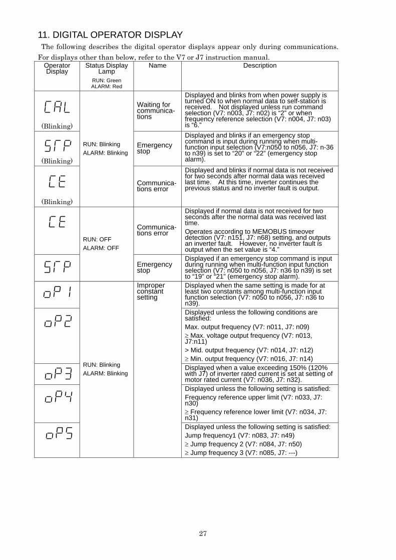
11. DIGITAL OPERATOR DISPLAY The following describes the digital operator displays appear only during communications. For displays other than below, refer to the V7 or J7 instruction manual.
Operator Display
Status Display Lamp
RUN: Green ALARM: Red
Name Description
(Blinking)
Waiting for communica-tions
Displayed and blinks from when power supply is turned ON to when normal data to self-station is received. Not displayed unless run command selection (V7: n003, J7: n02) is “2” or when frequency reference selection (V7: n004, J7: n03) is “6.”
(Blinking)
Emergency stop
Displayed and blinks if an emergency stop command is input during running when multi-function input selection (V7:n050 to n056, J7: n-36 to n39) is set to “20” or “22” (emergency stop alarm).
(Blinking)
RUN: Blinking ALARM: Blinking
Communica-tions error
Displayed and blinks if normal data is not received for two seconds after normal data was received last time. At this time, inverter continues the previous status and no inverter fault is output.
Communica-tions error
Displayed if normal data is not received for two seconds after the normal data was received last time.
27
Operates according to MEMOBUS timeover detection (V7: n151, J7: n68) setting, and outputs an inverter fault. However, no inverter fault is output when the set value is “4.”
RUN: OFF ALARM: OFF
Emergency stop
Displayed if an emergency stop command is input during running when multi-function input function selection (V7: n050 to n056, J7: n36 to n39) is set to “19” or “21” (emergency stop alarm).
Displayed when the same setting is made for at least two constants among multi-function input function selection (V7: n050 to n056, J7: n36 to n39).
Displayed unless the following conditions are satisfied: Max. output frequency (V7: n011, J7: n09) ≥ Max. voltage output frequency (V7: n013, J7:n11) > Mid. output frequency (V7: n014, J7: n12) ≥ Min. output frequency (V7: n016, J7: n14)
Displayed when a value exceeding 150% (120% with J7) of inverter rated current is set at setting of motor rated current (V7: n036, J7: n32).
RUN: Blinking ALARM: Blinking
Improper constant setting
Displayed unless the following setting is satisfied: Frequency reference upper limit (V7: n033, J7: n30) ≥ Frequency reference lower limit (V7: n034, J7: n31)
Displayed unless the following setting is satisfied: Jump frequency1 (V7: n083, J7: n49) ≥ Jump frequency 2 (V7: n084, J7: n50) ≥ Jump frequency 3 (V7: n085, J7: ---)