vs1053b ogg vorbis encoder vsmpg “vlsi … · finally, chapter7contains vlsi solution’s contact...
TRANSCRIPT

PUBLIC DOCUMENT
VS1053B OGG VORBIS ENCODER
VSMPG “VLSI Solution Audio Decoder”
Project Code:Project Name: VSMPG
All information in this document is provided as-is without warranty. Features aresubject to change without notice.
Revision HistoryRev. Date Author Description
1.70c 2012-11-16 HH Enhanced streaming documentation.1.70b 2011-06-29 HH Added .IMG files and example C source code.1.70 2010-09-09 HH Added Vox and Pause control for mono profiles.1.60d 2010-08-10 HH Corrected Figure 3 on page 15.1.60c 2010-05-10 HH Enhanced this document, removed XP/Vista demo.1.60b 2010-05-04 HH Corrected formatting error in this document.1.60 2010-03-30 HH Enhanced sound quality, added stereo VU meter.1.50 2009-07-02 HH Added byte alignment, mono channel selection.1.40 2009-03-24 HH SCI_CLOCKF bug fix.1.31 2009-02-26 HH Added Chapter 5.3.1.30 2009-01-15 HH Added sample counter.1.21 2008-11-21 HH Corrected contents for SCI_CLOCKF.1.20 2008-11-20 HH Many new features, see Chapter 6.1.10 2008-05-22 HH Improved quality, many new profiles.1.01 2007-12-21 HH Added XP/Vista demo binary.1.00 2007-12-03 HH Initial version.
Rev. 1.70c 2012-11-16 Page 1(39)

HH
VS1053B OGG VORBIS ENCODER VSMPG
Contents
VS1053b Ogg Vorbis Encoder Front Page 1
Table of Contents 2
1 Introduction 4
2 Using the Ogg Vorbis Encoder 52.1 Limitations and Requirements . . . . . . . . . . . . . . . . . . . . . . . . . 52.2 Ogg Vorbis Encoder Profiles . . . . . . . . . . . . . . . . . . . . . . . . . . 5
2.2.1 Profile Groups . . . . . . . . . . . . . . . . . . . . . . . . . . . . . 52.2.2 Profile Quality Settings . . . . . . . . . . . . . . . . . . . . . . . . . 6
2.3 Running the VS1053b Ogg Vorbis Encoder . . . . . . . . . . . . . . . . . 82.3.1 VS1053b Ogg Vorbis Encoder Registers . . . . . . . . . . . . . . . 82.3.2 Loading and Starting the Code . . . . . . . . . . . . . . . . . . . . 92.3.3 Reading Ogg Vorbis Data . . . . . . . . . . . . . . . . . . . . . . . 102.3.4 Reading Additional Data while Recording Ogg Vorbis . . . . . . . 112.3.5 Finishing Ogg Vorbis Recording . . . . . . . . . . . . . . . . . . . 11
2.4 Recording Levels and Automatic Gain Control (AGC) . . . . . . . . . . . . 122.4.1 Reading the Recording Level . . . . . . . . . . . . . . . . . . . . . 122.4.2 Setting AGC . . . . . . . . . . . . . . . . . . . . . . . . . . . . . . 132.4.3 Building a Useful VU Meter . . . . . . . . . . . . . . . . . . . . . . 142.4.4 Converting from Linear to Decibel Scale . . . . . . . . . . . . . . . 162.4.5 vs1053oggrec.c . . . . . . . . . . . . . . . . . . . . . . . . . . . . 17
2.5 Vox and Pause Operation . . . . . . . . . . . . . . . . . . . . . . . . . . . 222.5.1 Vox and Pause Registers . . . . . . . . . . . . . . . . . . . . . . . 232.5.2 Vox Output to GPIO4 . . . . . . . . . . . . . . . . . . . . . . . . . 23
2.6 Samplerate Considerations . . . . . . . . . . . . . . . . . . . . . . . . . . 242.7 Post-Processing the Recording with VorbisGain . . . . . . . . . . . . . . . 24
3 The Ogg Vorbis Format 253.1 Introduction to Ogg Vorbis . . . . . . . . . . . . . . . . . . . . . . . . . . . 25
3.1.1 Variable Bit-Rate . . . . . . . . . . . . . . . . . . . . . . . . . . . . 253.1.2 Transcoding . . . . . . . . . . . . . . . . . . . . . . . . . . . . . . . 26
3.2 Compressing into Ogg Vorbis with a PC . . . . . . . . . . . . . . . . . . . 273.2.1 Preparation . . . . . . . . . . . . . . . . . . . . . . . . . . . . . . . 273.2.2 Compressing CD-Quality Music . . . . . . . . . . . . . . . . . . . . 273.2.3 Compressing Speech . . . . . . . . . . . . . . . . . . . . . . . . . 29
3.3 Post-Processing with VorbisGain . . . . . . . . . . . . . . . . . . . . . . . 30
4 How to Load a Plugin 314.1 How to Load a .PLG File . . . . . . . . . . . . . . . . . . . . . . . . . . . . 314.2 How to Load an .IMG File . . . . . . . . . . . . . . . . . . . . . . . . . . . 32
4.2.1 Example Microcontroller .IMG File Decoder . . . . . . . . . . . . . 33
5 Building a Streaming System 345.1 Sample Counter . . . . . . . . . . . . . . . . . . . . . . . . . . . . . . . . 355.2 End-to-End Delay of a Streaming System . . . . . . . . . . . . . . . . . . 36
Rev. 1.70c 2012-11-16 Page 2(39)

HH
VS1053B OGG VORBIS ENCODER VSMPG
5.3 Playback Speed Adjustment . . . . . . . . . . . . . . . . . . . . . . . . . . 365.4 Streaming Example . . . . . . . . . . . . . . . . . . . . . . . . . . . . . . 37
6 Latest Version Changes 38
7 Contact Information 39
List of Figures
1 Example colour VU meter. . . . . . . . . . . . . . . . . . . . . . . . . . . . 142 Example monochrome VU meter. . . . . . . . . . . . . . . . . . . . . . . . 143 Real record display with monochrome VU meter. . . . . . . . . . . . . . . 154 Vox / Pause logic. . . . . . . . . . . . . . . . . . . . . . . . . . . . . . . . . 225 Streaming system using VS1053b. . . . . . . . . . . . . . . . . . . . . . . 34
Rev. 1.70c 2012-11-16 Page 3(39)

HH
VS1053B OGG VORBIS ENCODER VSMPG
1 Introduction
The VS1053b allows the user to encode files into the highly efficient Ogg Vorbis format.This makes it possible for the user to build a device that can record high-quality stereosound while retaining moderate file sizes.
This document is an instruction manual on how to use the VS1053b Ogg Vorbis encoderapplication as well as an introduction to the Ogg Vorbis format itself. Example code in Cis also provided.
Chapter 2 describes how to load and run different Ogg Vorbis profiles on a VS1053b. Italso discusses recording levels and recording level meters.
Chapter 3 briefly introduces the Ogg Vorbis format. It also has some suggestions onhow to encode data to Ogg Vorbis format as efficiently as possible on a PC. If you areunfamiliar with the Ogg Vorbis format, please read this chapter first.
Chapter 4 tells how to load a plugin code to a VS10XX chip.
Chapter 5 describes how a streaming VS1053b system can be built.
The document version history for the latest releases is provided in Chapter 6.
Finally, Chapter 7 contains VLSI Solution’s contact information.
Rev. 1.70c 2012-11-16 Page 4(39)

HH
VS1053B OGG VORBIS ENCODER VSMPG
2 Using the Ogg Vorbis Encoder
The VS1053b Ogg Vorbis Encoder application is provided as a plugin in the same pack-age as this document, downloadable athttp://www.vlsi.fi/en/support/software/vs10xxapplications.html .
Before loading the application into your VS1053b, select one of the profiles shown below.
2.1 Limitations and Requirements
• Maximum SPI (SCI) clock speed is 3.5 Mbit/s. If a higher speed is used, there maybe occasional data read errors.
2.2 Ogg Vorbis Encoder Profiles
There are 45 different Ogg Vorbis profiles available. They are divided into five groups,depending on their samplerate and number of channels.
2.2.1 Profile Groups
The five profile groups are presented below. As a comparison, bitrate figures for uncom-pressed 16-bit PCM (WAV) files with similar specifications are also shown.
Ogg Vorbis ProfilesProfile File SRate Ch BRat2 WAV3 Time Vox+name name1 Hz kbit/s kbit/s h/GB Pause4
Voice venc08k1qXX.plg 8000 1 15 128 149 YWideband Voice venc16k1qXX.plg 16000 1 28 256 79 YWideband Stereo Voice venc16k2qXX.plg 16000 2 49 512 45 NHiFi Voice venc44k1qXX.plg 44100 1 87 706 26 YStereo Music venc44k2qXX.plg 44100 2 135 1411 16 N
1 Replace XX with a quality value between 00 and 10. See Chapter 2.2.2 for details.2 Estimate for quality value 05. Actual bitrate depends on content being recorded.3 Comparison bitrate for a 16-bit WAV file with the same specifications.4 For details on Vox and Pause operation, see Chapter 2.5.
Rev. 1.70c 2012-11-16 Page 5(39)

HH
VS1053B OGG VORBIS ENCODER VSMPG
2.2.2 Profile Quality Settings
Each of the low-sample-rate profile groups has eleven quality profiles, numbered from00 to 10. The high-sample-rate profile groups have six quality profiles from 00 to 05.This chapter presents the five profile groups and gives estimates of typical bitrates thatcan be obtained with the profile.
In general, quality setting 05 is designed to be a typical value that gives good qualityfor the application. Qualities 00 and 01 are for emergency use only when there justisn’t storage space for better quality settings. High qualities, starting from 07 or 08,are intended for transparent sound quality, the intent being that compression cannot beheard anymore even under stringent circumstances.
The “Voice” Profiles
The “Voice” profiles are intended for speech applications.
These profiles support Vox and Pause.
VoiceProfile number 00 01 02 03 04 05 06 07 08 09 10Typical kbit/s 6 8 10 11 13 15 20 24 27 30 33
The “Wideband Voice” Profiles
“Wideband Voice” is intended to be used when high speech quality is required.
These profiles support Vox and Pause.
Wideband VoiceProfile number 00 01 02 03 04 05 06 07 08 09 10Typical kbit/s 6 10 14 18 23 28 37 45 52 58 63
The “Wideband Stereo Voice” Profiles
“Wideband Stereo Voice” is intended to be used when high speech quality with direc-tional information is required.
These profiles don’t support Vox and Pause.
Wideband Stereo VoiceProfile number 00 01 02 03 04 05 06 07 08 09 10Typical kbit/s 9 17 25 44 41 49 66 84 101 119 136
Rev. 1.70c 2012-11-16 Page 6(39)

HH
VS1053B OGG VORBIS ENCODER VSMPG
The “HiFi Voice” Profiles
When extremely high quality speech is required, use the “HiFi Voice” profiles.
These profiles support Vox and Pause. However, Vox works best with the “Voice” and“Wideband Voice” profiles.
HiFi VoiceProfile number 00 01 02 03 04 05Typical kbit/s 36 49 59 71 79 87
The “Music” Profiles
The “Music” profiles are intended for HiFi music, and are capable of offering very high-quality stereo sound.
These profiles don’t support Vox and Pause.
MusicProfile number 00 01 02 03 04 05Typical kbit/s 44 63 80 99 117 135
Rev. 1.70c 2012-11-16 Page 7(39)

HH
VS1053B OGG VORBIS ENCODER VSMPG
2.3 Running the VS1053b Ogg Vorbis Encoder
This chapter will describe how to load and run the Ogg Vorbis Encoder. A C languagesource file vs1053oggrec.c has been included in this package as an example.
2.3.1 VS1053b Ogg Vorbis Encoder Registers
Register Bits DescriptionSCI_MODE 14 Select MIC/LINE1
12 Set to 1 when told in the instructions1 VU meter stereo mode activation
SCI_AICTRL0 15:0 Maximum signal level, set to 0x8000 (mono) or 0x8080 (stereo)SCI_AICTRL1 15:0 Recording gain (1024 = 1×) or 0 for automatic gain controlSCI_AICTRL2 15:0 Maximum autogain amplification (1024 = 1×, 65535 = 64×)SCI_AICTRL3 0 W: Finish recording, set to 0
1 R: Recording finished, set to 02 R: There is at least one byte to read, set to 03 W: Input channel select (only mono profiles), 0 = left, 1 = right7:4 W: Max samples in frame = n× 4096, 0 = no limit15:8 R: The next data byte if available, set to 0
Before activating Ogg Vorbis recording, the user must initalize registers SCI_AICTRL0- SCI_AICTRL3. SCI_AICTRL1 and SCI_AICTRL2 can be altered during recording.
SCI_AICTRL0 records the maximum absolute value of the signal. The maximum valueof this linear register is 0x7FFF in mono mode, or 0x7F7F in stereo mode. For moreinformation on how to use this register, see Chapter 2.4.1. SCI_AICTRL0 is updatedonce for every Vorbis block, i.e. 10. . . 170 times per second with the current profiles.
SCI_AICTRL1 controls linear recording gain. 1024 is equal to digital gain 1 (recom-mended for best quality), 2048 is equal to digital gain 2, and so on. If the user wants touse automatic gain control (AGC), SCI_AICTRL1 should be set to 0. Speech applica-tions are often better off using some AGC, as this helps to get relatively uniform speechloudness in recordings.
SCI_AICTRL2 controls the maximum AGC gain if SCI_AICTRL1 is set to 0. This limitsamplification of noise when there is no signal. For more information on recording levels,see Chapter 2.4.
SCI_AICTRL3 offers run-time controls, channel selection for mono input, the maximumnumber of samples that are allowed in one Ogg frame with 4096 sample granularity, andthe next unread byte, if any. Normally 0 (no limit) is a good value for granularity, butstreaming applications often have maximum delay considerations, thus making limitingnecessary. Note that limiting frame size isn’t entirely accurate, so always select a maxi-mum frame size slightly lower than your absolute upper delay limit.Example: your samplerate is 44100 Hz and you want frame output at least every 500 ms.Then you’ll need samples at 22100 sample intervals. Round this downwards to the clos-est 4096 multiple, and you’ll get 16384 samples, so you’ll write 0x40 to SCI_AICTRL3.The bitrate penalty of this example is ≈0.5 kbit/s.For this to work your reads must be byte aligned as explained in Chapter 2.3.3.
For Vox operation controls, see Chapter 2.5.
Rev. 1.70c 2012-11-16 Page 8(39)
HH
VS1053B OGG VORBIS ENCODER VSMPG
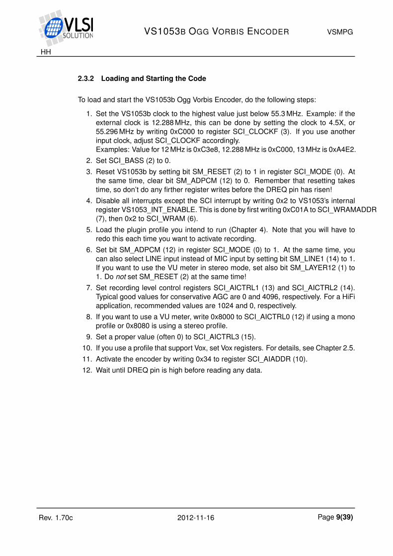
2.3.2 Loading and Starting the Code
To load and start the VS1053b Ogg Vorbis Encoder, do the following steps:
1. Set the VS1053b clock to the highest value just below 55.3 MHz. Example: if theexternal clock is 12.288 MHz, this can be done by setting the clock to 4.5X, or55.296 MHz by writing 0xC000 to register SCI_CLOCKF (3). If you use anotherinput clock, adjust SCI_CLOCKF accordingly.Examples: Value for 12 MHz is 0xC3e8, 12.288 MHz is 0xC000, 13 MHz is 0xA4E2.
2. Set SCI_BASS (2) to 0.3. Reset VS1053b by setting bit SM_RESET (2) to 1 in register SCI_MODE (0). At
the same time, clear bit SM_ADPCM (12) to 0. Remember that resetting takestime, so don’t do any firther register writes before the DREQ pin has risen!
4. Disable all interrupts except the SCI interrupt by writing 0x2 to VS1053’s internalregister VS1053_INT_ENABLE. This is done by first writing 0xC01A to SCI_WRAMADDR(7), then 0x2 to SCI_WRAM (6).
5. Load the plugin profile you intend to run (Chapter 4). Note that you will have toredo this each time you want to activate recording.
6. Set bit SM_ADPCM (12) in register SCI_MODE (0) to 1. At the same time, youcan also select LINE input instead of MIC input by setting bit SM_LINE1 (14) to 1.If you want to use the VU meter in stereo mode, set also bit SM_LAYER12 (1) to1. Do not set SM_RESET (2) at the same time!
7. Set recording level control registers SCI_AICTRL1 (13) and SCI_AICTRL2 (14).Typical good values for conservative AGC are 0 and 4096, respectively. For a HiFiapplication, recommended values are 1024 and 0, respectively.
8. If you want to use a VU meter, write 0x8000 to SCI_AICTRL0 (12) if using a monoprofile or 0x8080 is using a stereo profile.
9. Set a proper value (often 0) to SCI_AICTRL3 (15).10. If you use a profile that support Vox, set Vox registers. For details, see Chapter 2.5.11. Activate the encoder by writing 0x34 to register SCI_AIADDR (10).12. Wait until DREQ pin is high before reading any data.
Rev. 1.70c 2012-11-16 Page 9(39)

HH
VS1053B OGG VORBIS ENCODER VSMPG
2.3.3 Reading Ogg Vorbis Data
After Ogg Vorbis recording has been activated, registers SCI_HDAT0 and SCI_HDAT1have new functions.
The Ogg Vorbis bitstream buffer size is 4096 16-bit words, or 8 KiB. The fill status of thebuffer can be read from SCI_HDAT1. If SCI_HDAT1 is greater than 0, you can read thatmany 16-bit words from SCI_HDAT0.
If data is not read fast enough from SCI_HDAT0, the buffer overflows and returns toempty state. A data overflow will result in an incorrect file that may be undecodable.However, because of the large size of the bitstream buffer and the relatively slow bitratesof Ogg Vorbis, this situation should be easy to avoid.
Ogg frames are byte aligned. Because of the 16-bit SCI interface this may be a prob-lem for streaming applications where it is important to forward any Ogg frame as soonas possible: the latest frame may pend upon its last byte. If transferring data with alow delay is important, you can read whether there is one extra data byte by readingSCI_AICTRL3 twice in a row. The result of the latter read will contain the correct data:if bit 2 is 1, then bits 15:8 contain the odd byte. After reading the odd byte successfully,discard bits 15:8 of the next read from SCI_HDAT0 because they contain the same data.(NOTE: if you don’t stream or don’t need the shortest possible delay, you can ignore thisparagraph!)
If you are having trouble with receiving data, notice that all Ogg Vorbis files always beginwith the following 4 bytes: 0x4f 0x67 0x67 0x53 (the string “OggS”). If you get 0x67 0x4f0x53 0x67 (“gOSg”) instead, you are storing the least and most significant byte in the16-bit data words incorrectly. If you get 0x00 0x00 0x67 0x53, you have read data fromSCI_HDAT0 too soon after starting the application.
Rev. 1.70c 2012-11-16 Page 10(39)

HH
VS1053B OGG VORBIS ENCODER VSMPG
2.3.4 Reading Additional Data while Recording Ogg Vorbis
You can get extra side information while recording Ogg Vorbis data to see whetherVS1053b is still working. The following VS1053b X memory addresses may be readfor extra data:
X Memory Address Description0x8 16 LSb’s of recording time (seconds)0x9 16 MSb’s of recording time (seconds)0xC 16 LSb’s of average bitrate (bits/s)0xD 16 MSb’s of average bitrate (bits/s)
0x1800 16 LSb’s of sample counter0x1801 16 MSb’s of sample counter
Example: To read the average bitrate, do as follows. First write 0xC to SCI_WRAMADDR(7). Then read from SCI_WRAM (6). This is 16 least significant bits of the bitrate. Thenread the 16 more significant bits by reading SCI_WRAM again.
You can read the recording time as a sanity check that VS1053b is working: if theregister contents don’t change every second, you’ll have to take protective measures.
2.3.5 Finishing Ogg Vorbis Recording
To create fully compliant Ogg Vorbis files, Ogg Vorbis bitstreams need to be shut downproperly. The following algorithm can be used to implement this:
1. Set bit 0 of SCI_AICTRL3 (15) to 1.2. Continue reading data through SCI_HDAT0 and SCI_HDAT1 as usual, but check
SCI_AICTRL3’s bit 1 from time to time. When this bit turns to 1, the Ogg Vorbisencoder has finished writing to the buffer.
3. Write the remaining words from the bitstream buffer as normal using SCI_HDAT0and SCI_HDAT1.
4. Read SCI_AICTRL3 twice (changed from version 1.4!) and check whether bit 2 is1 in the latter read. If it is, then don’t write to the file the last byte (bits 7:0) of thelast word that have come through SCI_HDAT0.
5. Reset VS1053b to normal state using software reset. Remember to clear registerSCI_MODE (0) bit SM_ADPCM (12) if you don’t wish to start ADPCM recording.Remember to also set bit SM_LAYER12 (1) to an appropriate value.
6. If you want to restart recording, you have to completely reload and restart therecording application.
Rev. 1.70c 2012-11-16 Page 11(39)
HH
VS1053B OGG VORBIS ENCODER VSMPG
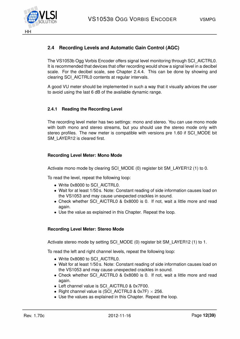
2.4 Recording Levels and Automatic Gain Control (AGC)
The VS1053b Ogg Vorbis Encoder offers signal level monitoring through SCI_AICTRL0.It is recommended that devices that offer recording would show a signal level in a decibelscale. For the decibel scale, see Chapter 2.4.4. This can be done by showing andclearing SCI_AICTRL0 contents at regular intervals.
A good VU meter should be implemented in such a way that it visually advices the userto avoid using the last 6 dB of the available dynamic range.
2.4.1 Reading the Recording Level
The recording level meter has two settings: mono and stereo. You can use mono modewith both mono and stereo streams, but you should use the stereo mode only withstereo profiles. The new meter is compatible with versions pre 1.60 if SCI_MODE bitSM_LAYER12 is cleared first.
Recording Level Meter: Mono Mode
Activate mono mode by clearing SCI_MODE (0) register bit SM_LAYER12 (1) to 0.
To read the level, repeat the following loop:
• Write 0x8000 to SCI_AICTRL0.• Wait for at least 1/50 s. Note: Constant reading of side information causes load on
the VS1053 and may cause unexpected crackles in sound.• Check whether SCI_AICTRL0 & 0x8000 is 0. If not, wait a little more and read
again.• Use the value as explained in this Chapter. Repeat the loop.
Recording Level Meter: Stereo Mode
Activate stereo mode by setting SCI_MODE (0) register bit SM_LAYER12 (1) to 1.
To read the left and right channel levels, repeat the following loop:
• Write 0x8080 to SCI_AICTRL0.• Wait for at least 1/50 s. Note: Constant reading of side information causes load on
the VS1053 and may cause unexpected crackles in sound.• Check whether SCI_AICTRL0 & 0x8080 is 0. If not, wait a little more and read
again.• Left channel value is SCI_AICTRL0 & 0x7F00.• Right channel value is (SCI_AICTRL0 & 0x7F) × 256.• Use the values as explained in this Chapter. Repeat the loop.
Rev. 1.70c 2012-11-16 Page 12(39)
HH
VS1053B OGG VORBIS ENCODER VSMPG
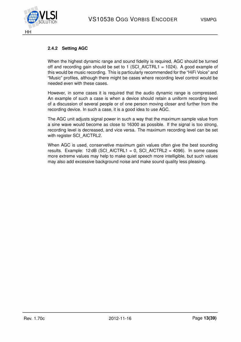
2.4.2 Setting AGC
When the highest dynamic range and sound fidelity is required, AGC should be turnedoff and recording gain should be set to 1 (SCI_AICTRL1 = 1024). A good example ofthis would be music recording. This is particularly recommended for the “HiFi Voice” and“Music” profiles, although there might be cases where recording level control would beneeded even with these cases.
However, in some cases it is required that the audio dynamic range is compressed.An example of such a case is when a device should retain a uniform recording levelof a discussion of several people or of one person moving closer and further from therecording device. In such a case, it is a good idea to use AGC.
The AGC unit adjusts signal power in such a way that the maximum sample value froma sine wave would become as close to 16300 as possible. If the signal is too strong,recording level is decreased, and vice versa. The maximum recording level can be setwith register SCI_AICTRL2.
When AGC is used, conservetive maximum gain values often give the best soundingresults. Example: 12 dB (SCI_AICTRL1 = 0, SCI_AICTRL2 = 4096). In some casesmore extreme values may help to make quiet speech more intelligible, but such valuesmay also add excessive background noise and make sound quality less pleasing.
Rev. 1.70c 2012-11-16 Page 13(39)

HH
VS1053B OGG VORBIS ENCODER VSMPG
2.4.3 Building a Useful VU Meter
In an encoder application, if the recording level is too low, extraneous background noisemay be introduced to the sound. Conversely, if the recording level is so high that thehighest values cannot be represented numerically, signal clipping occurs, and this maycause severe distortion to sound.
In a recording device, it is useful to have a VU meter that shows the signal level so thatboth too low signal levels and clipping is avoided. This is very important so that the userhas a chance to either adjust the recording or input signal level.
0−6−12−20−30−40
−40 dB = 161
−30 dB = 512
−20 dB = 1625
−12 dB = 4096
−6 dB = 8192
0 dB = 16384
+5 dB = 29193
OVERLOAD = 29193
+5
OVERLOAD
Figure 1: Example colour VU meter.
0−6−12−20−30−40 +5
OVERLOAD
Figure 2: Example monochrome VU meter.
Figures 1 and 2 show example VU meters. The 0 dB reference point has been set to sig-nal level 16384, which is one half of the maximum amplitude, leaving a 6 dB headroomfor the device.
The lowest signal level shown is a choice that can vary a lot depending on the appli-cation. While -40 dB is a high-fidelity favourite, a VU meter will work just as well with alower limit of -20 dB. If display space is scarce, low limit could even be set to -12 dB.
Between -6 and +6 dB the VU meter precision should preferably be 1 dB, and at most2 dB. Below -12 dB step size can be several decibels.
The important thing in a VU meter is to visually show the user that it is not recommendedto regularly use the highest 6 dB of the recording scale, and that an overload situation(≥ +5dB, or over linear value 29193) is an error condition. To help this the OVERLOADsymbol should be kept lit or blinking for at least 2 seconds each time an overload situa-tion occurs. Many of these cues are often ignored in digital VU meters, and partly as aresult of this even professional recordings are all too often made at recording levels thatdestroy signal integrity.
Rev. 1.70c 2012-11-16 Page 14(39)

HH
VS1053B OGG VORBIS ENCODER VSMPG
Figure 3: Real record display with monochrome VU meter.
Figure 3 shows a real implementation of a recording display that uses a MonochromeVU Meter. Information shown on the top line includes recording time, free disc space,overload warning and a bitrate counter. All this data except from the free disc spacenumber have been obtained from the VS1053b Ogg Vorbis Encoder.
Recording gain and AGC can be set at the center of the screen if a profile is used thatsupport these functions. However, they are greyed out in this picture because they arenot available in the Stereo Music profile that has been used.
The VU Meter is at the bottom. The solid line is the current recording level as readfrom SCI_AICTRL0 and converted to Decibel scale as shown in Chapter 2.4.4. Thegreyed line is the top level of the last 3 seconds. If the greyed line ≥ +5dB, the orangeOVERLOAD message blinks twice a second for three seconds.
Rev. 1.70c 2012-11-16 Page 15(39)

HH
VS1053B OGG VORBIS ENCODER VSMPG
2.4.4 Converting from Linear to Decibel Scale
To convert from linear to dB scale, use the formuladB = 20× log10(
m32768) + 96
where dB is the result and m is a value returned by the Recording Level Meter.
To implement a good approximation of this formula from linear to dB scale on architec-tures where multiplications and logarithms are expensive operations, the following codecan be used:
const unsigned short linToDBTab[5] = {36781, 41285, 46341, 52016, 58386};
/*
Converts a linear 16-bit value between 0..65535 to decibels.
Reference level: 32768 = 96dB (largest VS1053b number is 32767 = 95dB).
Bugs:
- For the input of 0, 0 dB is returned, because minus infinity cannot
be represented with integers.
- Assumes a ratio of 2 is 6 dB, when it actually is approx. 6.02 dB.
*/
unsigned short LinToDB(unsigned short n) {
int res = 96, i;
if (!n) /* No signal should return minus infinity */
return 0;
while (n < 32768U) { /* Amplify weak signals */
res -= 6;
n <<= 1;
}
for (i=0; i<5; i++) /* Find exact scale */
if (n >= linToDBTab[i])
res++;
return res;
}
Rev. 1.70c 2012-11-16 Page 16(39)

HH
VS1053B OGG VORBIS ENCODER VSMPG
2.4.5 vs1053oggrec.c
The file vs1053oggrec.c, quoted below, has also been included in the VS1053b OggVorbis Encoder package.
/*
Example code how to implement VS1053 Ogg Vorbis recording using
the VS1053 Ogg Vorbis Recording plugin. The code is generic enough
so that it should pretty much compile and run on any microcontroller.
The code makes the following assumptions:
- <stdio.h> functions fopen(), fclose(), fgetc() and fputc() are available
- The following VS1053 interfacing functions must exist:
- void Write1053Sci(int regNo, u_int16 value): writes value to SCI register
- u_int16 Read1053Sci(int regNo): reads value from SCI register
- WaitFor1053Dreq(int timeOut): Waits for 1 microsecond, then until
DREQ goes up or timeOut is reached (timeOut=1 is 10 ms).
- EndRecording() function must exist, which returns non-zero when the user
has requested that recording should be finished.
NOTE!
This code serves as an example of how to create generic C microcontroller
code for VS1053 recording.
Author: Henrik Herranen / VLSI Solution 2011.
Copyright: Use freely for any project with any VLSI Solution's IC.
Warranty: Absolutely none whatsoever.
*/
#include <stdio.h>
#include <stdlib.h>
#include <string.h>
/* Change these if they don't match you architecture. */
typedef unsigned short u_int16;
typedef short s_int16;
typedef unsigned long u_int32;
typedef long s_int32;
#define SCIR_MODE 0
#define SCIR_STATUS 1
#define SCIR_BASS 2
#define SCIR_CLOCKF 3
#define SCIR_DECODE_TIME 4
#define SCIR_AUDATA 5
#define SCIR_WRAM 6
#define SCIR_WRAMADDR 7
#define SCIR_HDAT0 8
#define SCIR_HDAT1 9
#define SCIR_AIADDR 10
#define SCIR_VOL 11
#define SCIR_AICTRL0 12
Rev. 1.70c 2012-11-16 Page 17(39)

HH
VS1053B OGG VORBIS ENCODER VSMPG
#define SCIR_AICTRL1 13
#define SCIR_AICTRL2 14
#define SCIR_AICTRL3 15
/* returns minimum of two given numbers */
#define min(a,b) (((a)<(b))?(a):(b))
/* Loads an image file into VS1053 from a file. */
auto u_int16 SpiLoadImageInto1053(FILE *fp);
/* Main recording program */
void main(void) {
FILE *outFP, *inFP;
u_int16 pluginStartAddr;
u_int16 state = 0;
u_int16 i;
u_int16 wordsToRead;
u_int16 wordsWaiting;
/* Perform Microcontroller specific initializations here. */
/* Following VS1053 operations are according to the
VS1053b Ogg Vorbis Encoder application manual. For
details read Chapter Loading and Starting the Code. */
/* Set VS1053 clock to 4.5x = 55.3 MHz */
Write1053Sci(SCIR_CLOCKF, 0xC000);
WaitFor1053Dreq(TIMER_TICKS/10);
/* Clear SCI_BASS */
Write1053Sci(SCIR_BASS, 0);
/* Reset VS1053 */
Write1053Sci(SCIR_MODE, SMF_SDINEW | SMF_RESET);
WaitFor1053Dreq(TIMER_TICKS/10); /* Wait until DREQ is high or 100 ms */
// Disable all interrupts except SCI
Write1053Sci(SCIR_WRAMADDR, VS1053_INT_ENABLE);
Write1053Sci(SCIR_WRAM, 0x2);
/* Load the recorder application to VS1053
This source code uses .img image files for loading.
If you use .plg files, use the source as described
in the VS1053b Ogg Vorbis Encoder application manual. */
inFP = fopen("venc44k2q05.img", "rb");
if (!inFP)
goto end;
pluginStartAddr = SpiLoadImageInto1053(inFP);
fclose(inFP);
Rev. 1.70c 2012-11-16 Page 18(39)
HH
VS1053B OGG VORBIS ENCODER VSMPG
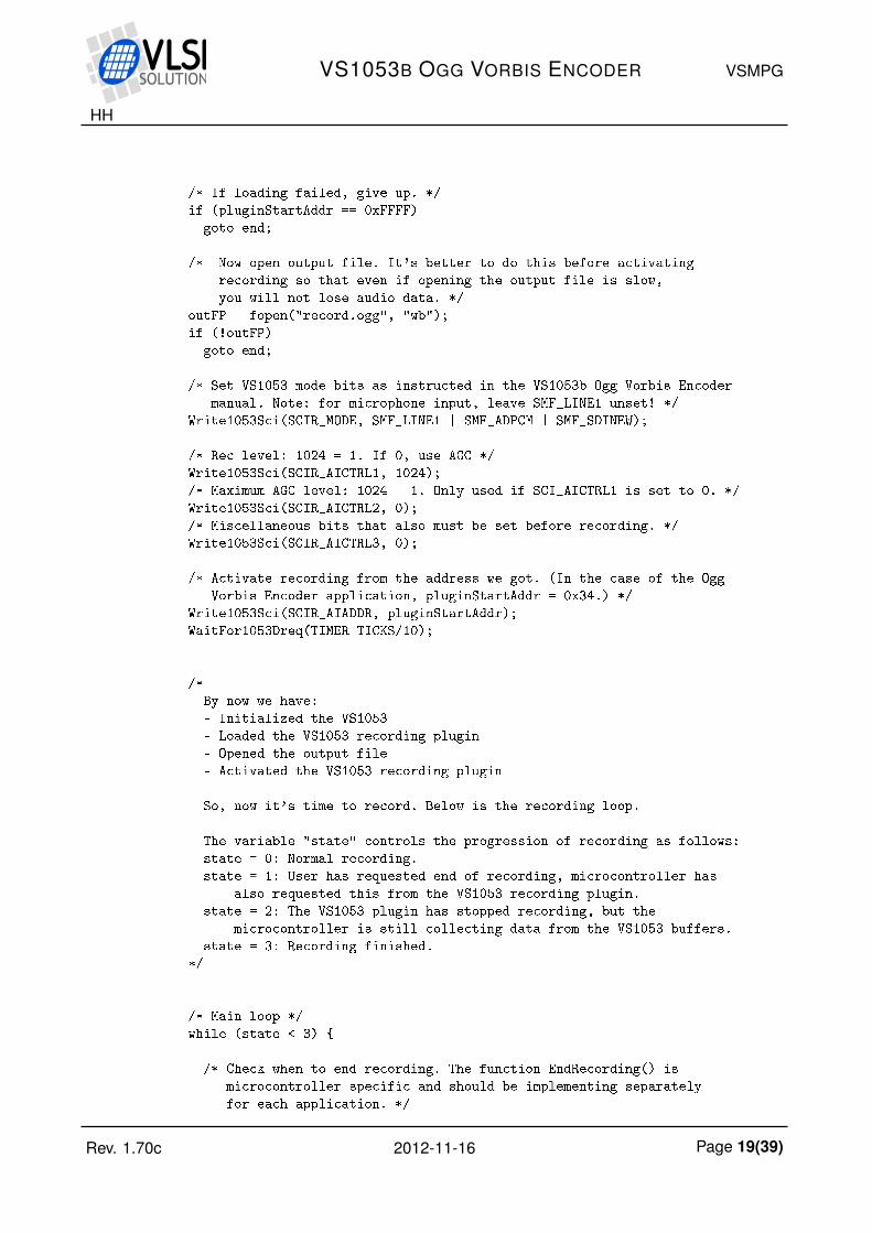
/* If loading failed, give up. */
if (pluginStartAddr == 0xFFFF)
goto end;
/* Now open output file. It's better to do this before activating
recording so that even if opening the output file is slow,
you will not lose audio data. */
outFP = fopen("record.ogg", "wb");
if (!outFP)
goto end;
/* Set VS1053 mode bits as instructed in the VS1053b Ogg Vorbis Encoder
manual. Note: for microphone input, leave SMF_LINE1 unset! */
Write1053Sci(SCIR_MODE, SMF_LINE1 | SMF_ADPCM | SMF_SDINEW);
/* Rec level: 1024 = 1. If 0, use AGC */
Write1053Sci(SCIR_AICTRL1, 1024);
/* Maximum AGC level: 1024 = 1. Only used if SCI_AICTRL1 is set to 0. */
Write1053Sci(SCIR_AICTRL2, 0);
/* Miscellaneous bits that also must be set before recording. */
Write1053Sci(SCIR_AICTRL3, 0);
/* Activate recording from the address we got. (In the case of the Ogg
Vorbis Encoder application, pluginStartAddr = 0x34.) */
Write1053Sci(SCIR_AIADDR, pluginStartAddr);
WaitFor1053Dreq(TIMER_TICKS/10);
/*
By now we have:
- Initialized the VS1053
- Loaded the VS1053 recording plugin
- Opened the output file
- Activated the VS1053 recording plugin
So, now it's time to record. Below is the recording loop.
The variable "state" controls the progression of recording as follows:
state = 0: Normal recording.
state = 1: User has requested end of recording, microcontroller has
also requested this from the VS1053 recording plugin.
state = 2: The VS1053 plugin has stopped recording, but the
microcontroller is still collecting data from the VS1053 buffers.
state = 3: Recording finished.
*/
/* Main loop */
while (state < 3) {
/* Check when to end recording. The function EndRecording() is
microcontroller specific and should be implementing separately
for each application. */
Rev. 1.70c 2012-11-16 Page 19(39)

HH
VS1053B OGG VORBIS ENCODER VSMPG
if (EndRecording() && !state) {
state = 1;
Write1053Sci(SCIR_AICTRL3, 1); // Send VS1053 request to stop recording
}
/* See how many 16-bit words there are waiting in the VS1053 buffer */
wordsWaiting = Read1053Sci(SCIR_HDAT1);
/* If user has requested stopping recording, and VS1053 has
stopped recording, proceed to the next state. */
if (state == 1 && Read1053Sci(SCIR_AICTRL3) & (1<<1)) {
state = 2;
/* It is important to reread the HDAT1 register once after
VS1053 has stopped. Otherwise there is the chance that
a few more words have just arrived although we just
read this register. So, do NOT optimize the following
line away! */
wordsWaiting = Read1053Sci(SCIR_HDAT1);
}
/* Read and transfer whole 512-byte (256-word) disc blocks at
the time. The only exception is when recording ends: then
allow for a non-full block. */
while (wordsWaiting >= ((state < 2) ? 256 : 1)) {
wordsToRead = min(wordsWaiting, 256);
wordsWaiting -= wordsToRead;
/* If this is the very last block, read one 16-bit word less,
because it will be handled later separately. */
if (state == 2 && !wordsWaiting)
wordsToRead--;
/* Transfer one full data block, or if this is the very last
block, all data that's left except for the last word. */
{
u_int16 t;
u_int16 i;
for (i=0; i<wordsToRead; i++) {
t = Read1053Sci(SCIR_HDAT0);
fputc(t >> 8 , outFP);
fputc(t & 0xFF, outFP);
}
}
/* If this is the last data block... */
if (wordsToRead < 256) {
u_int16 lastWord;
state = 3;
/* ... read the very last word of the file */
lastWord = Read1053Sci(SCIR_HDAT0);
/* Always write first half of the last word. */
fputc(lastWord >> 8 , outFP);
Rev. 1.70c 2012-11-16 Page 20(39)

HH
VS1053B OGG VORBIS ENCODER VSMPG
/* Read twice SCIR_AICTRL3, then check bit 2 of latter read. */
Read1053Sci(SCIR_AICTRL3);
if (!(Read1053Sci(SCIR_AICTRL3) & (1<<2))) {
/* Write last half of the last word only if bit 2 is clear. */
fputc(lastWord & 0xFF, outFP);
}
} /* if (wordsToRead < 256) */
} /* while (wordsWaiting >= ((state < 2) ? 256 : 1)) */
} /* while (state < 3), end of main loop */
/* That's it! We've perfectly recorded an Ogg Vorbis file, so now
we only need to close the file and be happy about it. */
fclose(outFP);
end:
/* Finally, reset VS1053 so that we will hear no more monitor audio */
Write1053Sci(SCIR_MODE, SMF_SDINEW | SMF_RESET);
/* End up in infinite loop */
while (1)
;
}
Rev. 1.70c 2012-11-16 Page 21(39)

HH
VS1053B OGG VORBIS ENCODER VSMPG
2.5 Vox and Pause Operation
Vox / Pause allows the user to temporarily pause recording either based on audio con-tent or direct user control. (For Ogg Vorbis Encoder Profiles that support Vox / Pauseoperation, see Chapter 2.2.1.)
Vox control allows the unit to record only when someone is actually speaking. An audiobuffer makes it so that recording resumes slightly “before” the moment when speech isdetected, so in typical cases no syllables are lost at the beginning of a sentence.
Pause override allows the user to set and clear pause mode at will. This allows the userto create a system where pause mode may be activated with a pause switch, like in atraditional tape recorder.
buffer
Sample
Pause
logic
Pause override
input
Line/Mic Samples Samples Bitstream
Samples
A/D Encoder
Vox level
detector
Figure 4: Vox / Pause logic.
Figure 4 presents the pause logic. Input samples are fed to the Vox detector through ahigh-pass filter. If pause hasn’t been overridden by the user, the Vox detector level isused to control pause mode.
Note: It is not recommended to use Vox with a streaming system. When pause isactivated either by the user or by Vox, the sample counter (Chapter 5.1) stops and noOgg frames, not even empty ones, are output by the Encoder.
Rev. 1.70c 2012-11-16 Page 22(39)

HH
VS1053B OGG VORBIS ENCODER VSMPG
2.5.1 Vox and Pause Registers
X Mem Addr Name Default Description0x1808 OffLimit 0x18 Signal limit for Vox pause0x1809 OnLimit 0x20 Signal limit for Vox record0x180A OffTimeLSW 0x7700 16 LSb’s of pause delay time in 1/48000 s0x180B OffTimeMSW 0x1 16 MSb’s of pause delay time in 1/48000 s0x180F PauseCtl 0x2 Vox control / Pause override
0 = Automatic Vox operation1 = forbidden2 = Pause override: Normal recording3 = Pause override: Pause on
If the signal after the high-pass filter is below OffLimit for more than OffTime 48 kHzsamples, and if PauseCtl = 0, or if PauseCtl = 3, then pause mode is activated. Defaultvalue of OffTime = 0x17700 = 96000 equals two seconds. Note that OffTime is alwayscalculated in the 48 kHz domain regardless of the samplerate of the Ogg Vorbis EncoderProfile.
If even a single sample goes above OnLimit, and if PauseCtl = 0, or if PauseCtl = 2, thenpause mode is deactivated and normal recording continues.
OffLimit and OnLimit are linear values. Thus, doubling the value lifts the limit by 6 dB.Having two separate values for the limits allow for hysteresis between stopping andrestarting recording. OnLimit must always be greater than or equal to OffLimit.
Example: To set OffTime, do as follows. First write 0x180A to SCI_WRAMADDR (7).Then write 16 least significant bits of OffTime (e.g. 0x7700) to SCI_WRAM (6). Thenwrite the 16 most significant bits by writing (e.g. 0x1) to SCI_WRAM (6) again.
Vox and Pause registers may be written to while the Ogg Vorbis Encoder is active.
2.5.2 Vox Output to GPIO4
It is optionally possible for the user to optionally see the current status of Vox in GPIO4.To activate this option, do the following steps before activating the Ogg Vorbis Encoder:
• Write 0xC017 to SCI_WRAMADDR (7).• Read value x from SCI_WRAM (6).• Set x = x|16;• Write 0xC017 to SCI_WRAMADDR (7).• Write new value x to SCI_WRAM (6).
After this operation, whenever GPIO4 is low, normal recording is done. When GPIO4 ishigh, then pause mode (either by Vox or user control) is active. So, whenever GPIO4goes high, the main controller may read all data that is left in the buffer, and set itself tosleep for as long until GPIO4 goes low again.
Rev. 1.70c 2012-11-16 Page 23(39)

HH
VS1053B OGG VORBIS ENCODER VSMPG
2.6 Samplerate Considerations
The Ogg Vorbis encoder cannot always work at exactly the right samplerate. To be exact,the samplerate is accurate only when the input clock is 12.288 MHz and the nominalsamplerate of a profile is either 8000 Hz or 16000 Hz. In all other cases the sampleratecan be calculated as follows. First let:
• fi =input clock divided by 4000 (same value that you write to SC_FREQ (bits 10:0)of register SCI_CLOCKF, or 3072 if you have written 0 to these bits to indicate12.288 MHz clock).• fn =nominal samplerate of the profile (8000, 16000 or 44100).• r = 3 if fn = 8000, otherwise r = 2.• Now let u = fn × r.
• Let d = bfi×2000+u2
u c• Now our real samplerate fs =
2000×fid×r
Example: We are running at an input clock of 12.288 MHz and we are running the StereoMusic profile that has a nominal samplerate of 44100 Hz.
First fi = 122880004000 = 3072.
Because fn = 44100, then r = 2.Thus u = 44100× 2 = 88200.This leads to d = b3072×2000+ 88200
288200 c = 70
And, finally, our real samplerate fs =2000×3072
70×2 ≈ 43885.7 (Hz)
As can be seen, in this example the nominal and real samplerate have a difference of0.5 %. While this is normally not significant, it is good to know and important in the caseof streaming.
2.7 Post-Processing the Recording with VorbisGain
It is recommended to post-process your own recording later on a PC machine usingVorbisGain to get equal loudness with other recordings. For details, see Chapter 3.3.
Rev. 1.70c 2012-11-16 Page 24(39)

HH
VS1053B OGG VORBIS ENCODER VSMPG
3 The Ogg Vorbis Format
This chapter gives a brief introduction to the Ogg Vorbis format and presents recommen-dations for basic parameters when transcoding MP3 files or compressing CD contentinto Ogg Vorbis files on a PC. The intent is to give VLSI Solution’s customers informa-tion on how to create high-quality Ogg Vorbis content.
Before using the information in this document, you should get the free Ogg Vorbis en-coder “oggenc”, minimum version 1.0.2 (2005), or a version with aoTuV tunings. Whilethe instructions will work with older versions, sound quality will not be as good. Down-load oggenc at http://www.vorbis.com/ .
It is also strongly encouraged to get VorbisGain, a program that tags files with loudnessinformation (Chapter 3.3). For this example, vorbisgain v0.36 has been used. DownloadVorbisGain at http://www.sjeng.org/vorbisgain.html .
3.1 Introduction to Ogg Vorbis
Ogg Vorbis is a license-free audio codec that allows for high-quality sound around alarge gamut of bit-rates, ranging from roughly 10 to 500 kbit/s.
With a given bit-rate, Vorbis is capable of surpassing the quality of MP2, MP3, WMAand AAC LC, particularly in low-bit-rate applications.
An Ogg Vorbis file is a Vorbis compressed file that has been encapsulated inside anOgg stream. The default file extension for Ogg Vorbis files is “.ogg”.
An Ogg Vorbis file consists of two major parts: header and actual data. Every OggVorbis file begins with a header which contains compression tables that the decoderneeds to correctly decode first. After the header has been fully received, Vorbis audiomay be decoded. The size of the header information is around 4 KiB for most encoders.(However, for VLSI Solution’s VS1053b encoder, header size is only roughly 1.5 KiB.)
After the header has been decoded, full random access is available in an Ogg Vorbisfile. As opposed to many other formats, an Ogg Vorbis file contains its own time code, soabsolute position in a file can be displayed after random access operations (fast forward/ rewind).
Ogg Vorbis is not particularly well suited for encoding very short, low bit-rate samples.E.g. a 16 kbit/s audio sample that lasts for one second would take 2 KiB for the actualaudio data, so the default 4 KiB header triples the file size. However, for normal appli-cations where audio lasts for more than 10 seconds, this header overhead is negligible.
3.1.1 Variable Bit-Rate
For a long time almost all MP3 files had a constant bit-rate, typically 128 kbit/s. Whileconstant bit-rate (CBR) makes it easy to calculate a relation between file size/position
Rev. 1.70c 2012-11-16 Page 25(39)

HH
VS1053B OGG VORBIS ENCODER VSMPG
and song length, and while it makes it easier to stream files, CBR is not optimal for qual-ity. When there is a difficult passage in music, there may not be enough bits available toencode audio flawlessly. Conversely, in passages that are easier to encode there maybe bits left unused because the encoder didn’t need all the bits available in the bitstream.
Where CBR tries to keep the bit-rate constant regardless of content, Variable Bit-Rate(VBR) tries to keep quality constant. This will have the effect of changing the bit-rate ofthe file depending on how difficult a particular portion of music is to encode. Becausesound quality is always kept constant, VBR has a bit advantage to CBR. Thus, VBRallows either for smaller files with the same perceived sound quality or equally sizedfiles with better perceived sound quality.
Ogg Vorbis is by nature a variable bit-rate format and works best when this feature isnot limited. Depending on the material the bit-rate can have significant fluctuations: e.g.songs that have been compressed with a quality setting with a nominal bit-rate of 96kbit/s can easily have average bit-rates between 80 to 105 kbit/s, or even more withextreme material.
3.1.2 Transcoding
Transcoding is the process of converting from one lossy format to another, like from MP3to Ogg Vorbis.
It is important to understand that although Ogg Vorbis is a better format than MP3,transcoding never enhances sound quality. What has been lost in the initial MP3 com-pression stage, will stay lost when converting to Ogg Vorbis, and there will always besome additional quality loss. While the extra quality loss can be small enough that itmay be impossible to tell, the end result still is never better than the original file was.
If possible, it it recommended that users should avoid transcoding to avoid generationloss. If transcoding is done (e.g. to get smaller files for a portable device), it is a goodidea to keep the original files.
For best results, compress Ogg Vorbis files from uncompressed sources, like CDs.
Rev. 1.70c 2012-11-16 Page 26(39)

HH
VS1053B OGG VORBIS ENCODER VSMPG
3.2 Compressing into Ogg Vorbis with a PC
The whole process of getting Ogg Vorbis files looks roughly like this:
• Preparation: Decode an MP3 / WMA / AAC etc file or preferably rip a CD to WAVformat and make sure that you have “oggenc” (Chapter 3.2.1).• Compression to Ogg Vorbis (Chapters 3.2.2 and 3.2.3).• Optional post-processing with VorbisGain (Chapter 3.3).
3.2.1 Preparation
If you intend to transcode (=recompress) MP3 files, you first have to convert them to 16-bit RIFF WAV format (usually known for a “.wav” file name extension). However, beforeyou do that, please have a look at Chapter 3.1.2 for details on transcoding.
If you encode CDs, you have to make sure they are read initially into WAV format. It isrecommended to use CD sources for compression if possible.
When you have audio in WAV format, you can use oggenc to compress files, either instereo or mono.
Before continuing to the next stage, make sure you have the free Ogg Vorbis encoder“oggenc”, minimum version 1.0.2 (2005).
3.2.2 Compressing CD-Quality Music
If we assume the input file is called file.wav and the output is to be called file.ogg, thefollowing parameters may be used.
It is assumed that the input audio is sampled at the CD 44.1 kHz sample rate. Whilethese commands will also work for other samplerates, quality and file sizes may differ.
For each quality setting, the table shows the command needed to convert the file, atypical bit-rate for that quality, how many hours of music could be stored to a 1 gibibytememory card, and a short description of the mode. For comparison purposes, also anuncompressed CD bitstream is shown in the table.
CD music compressionCommand Typ. Hours/ Description
kbit/s 1 GiBoggenc -q -1 file.wav 45 53 Smallest files size, better than 96 kbit/s MP3oggenc -q 0 file.wav 64 37 Ok quality, equals 112 kbit/s MP3oggenc -q 2 file.wav 96 25 Better than most 128 kbit/s MP3 filesoggenc -q 4 file.wav 128 19 Often CD transparentoggenc -q 6 file.wav 192 12 CD quality almost alwaysCD 1411 1.7 Uncompressed CD
Rev. 1.70c 2012-11-16 Page 27(39)

HH
VS1053B OGG VORBIS ENCODER VSMPG
Graphical front-ends usually contain one or several CBR bit-rate slider(s) and a qualityslider that usually goes from -1 to 10. CBR sliders should be deactivated, and the qualityslider should be set to the “-q” value presented in the table.
Rev. 1.70c 2012-11-16 Page 28(39)

HH
VS1053B OGG VORBIS ENCODER VSMPG
3.2.3 Compressing Speech
Speech requires different coding parameters than music. First, speech can usuallybe coded in mono, so all the following examples convert audio to mono. Also, to getsmaller files, speech bandwidth can usually be suppressed without adversely affectingintelligibility.
The following table shows the command needed to convert a speech file called file.wav,a typical bit-rate for that quality, how many hours of music could be stored to a 1 gibibytememory card, and a short description of the mode.
Speech compressionCommand Typ. Hours/ Description
kbit/s 1 GiB
oggenc �downmix �resample 4000 -q -1 file.wav 6 400 Very low bandwidthoggenc �downmix �resample 6000 -q -1 file.wav 8 300 Near mobile phone qualityoggenc �downmix �resample 8000 -q -1 file.wav 9 265 Slightly better than mobile phoneoggenc �downmix �resample 8000 -q 0 file.wav 13 184 Clean 3 kHz bandwidth soundoggenc �downmix �resample 11025 -q -1 file.wav 14 170 Toy application qualityoggenc �downmix �resample 11025 -q 0 file.wav 17 140 Cleaner toy applicationoggenc �downmix �resample 11025 -q 1 file.wav 20 119 Clean sound, 5 kHz bandwidthoggenc �downmix �resample 16000 -q 1 file.wav 24 99 Wideband (7 kHz) soundoggenc �downmix �resample 22050 -q 1 file.wav 30 80 10 kHz bandwidthoggenc �downmix �resample 44100 -q 0 file.wav 36 66 Full bandwidth (15+ kHz)oggenc �downmix �resample 44100 -q 1 file.wav 42 57 Cleaner soundoggenc �downmix �resample 44100 -q 2 file.wav 48 50 Close to transparentoggenc �downmix �resample 44100 -q 5 file.wav 80 30 CD quality (but mono)
The “�downmix” option converts sound to mono and the “-q” control works as in Chap-ter 3.2.2. Unfortunately, many graphical front-ends are missing the “�resample” option,which is a very powerful parameter for speech compression. If your program missesthis slider, you either have to fill the missing values in a command option window orcompress your files from oggenc’s command line mode.
Rev. 1.70c 2012-11-16 Page 29(39)

HH
VS1053B OGG VORBIS ENCODER VSMPG
3.3 Post-Processing with VorbisGain
Although the original CD standard defines a reference loudness that should be usedfor CD recording, current CDs no longer follow that standard. Because of this unequalloudness of CDs, songs compressed from CDs may have wildly differing subjective loud-ness, a phenomenon that is known to most users of portable digital audio players.
VorbisGain is a program that uses a psycho-acoustical model to determine an actual,perceived loudness of an audio track or album, and tags this information to the headersof an Ogg Vorbis file. This makes it possible for a VorbisGain aware decoder to adjustits output volume accordingly, and thus equalize loudness differences of songs withouta need to recompress them.
Using VorbisGain on all Vorbis songs will enhance the user’s listening experience be-cause there is no need to turn volume up and down between songs. Many Ogg Vorbisplayback programs and plug-ins for PC’s as well as all VLSI Solution’s Ogg Vorbis de-coder chips are compatible with VorbisGain.
Rev. 1.70c 2012-11-16 Page 30(39)

HH
VS1053B OGG VORBIS ENCODER VSMPG
4 How to Load a Plugin
4.1 How to Load a .PLG File
A plugin file (.plg) contains a data file that contains one unsigned 16-bit vector calledplugin. The file is in an interleaved and RLE compressed format. An example of aplugin vector is:
const unsigned short plugin[10] = { /* Compressed plugin */
0x0007, 0x0001, 0x8260,
0x0006, 0x0002, 0x1234, 0x5678,
0x0006, 0x8004, 0xabcd,
};
The vector is decoded as follows:
1. Read register address number addr and repeat number n.2. If n & 0x8000U, write the next word n times to register addr.3. Else write next n words to register addr.4. Continue until table has been exhausted.
The example vector first tells to write 0x8260 to register 7. Then write 2 words, 0x1234and 0x5678, to register 6. Finally, write 0xabcd 4 times to register 6.
Assuming the vector is in vector plugin[], a full decoder in C language is providedbelow:
void WriteVS10xxRegister(unsigned short addr, unsigned short value);
void LoadUserCode(void) {
int i = 0;
while (i<sizeof(plugin)/sizeof(plugin[0])) {
unsigned short addr, n, val;
addr = plugin[i++];
n = plugin[i++];
if (n & 0x8000U) { /* RLE run, replicate n samples */
n &= 0x7FFF;
val = plugin[i++];
while (n--) {
WriteVS10xxRegister(addr, val);
}
} else { /* Copy run, copy n samples */
while (n--) {
val = plugin[i++];
WriteVS10xxRegister(addr, val);
}
}
}
}
Rev. 1.70c 2012-11-16 Page 31(39)

HH
VS1053B OGG VORBIS ENCODER VSMPG
4.2 How to Load an .IMG File
The VS1053 image format is a bootable / loadable binary format with a three-byteheader, followed by one or more boot records. The default image file suffix is “.IMG”.
The 3-byte header is shown below:
VS1053 Boot Header, begins the fileName Bytes DescriptionHEADER 3 “P&H” (0x50, 0x26, 0x48)
A boot record is shown below:
VS1053 Boot Record, from 1 to n, last is always TYPE = ExecuteName Bytes DescriptionTYPE 1 0 = Instruction memory
1 = X data memory2 = Y data memory3 = Execute
L1 L0 2 LEN = 256×L1 + L0A1 A0 2 ADDR = 256×A1 + A0D1 D0 LEN DATA = 256×D1 + D0, repeat LEN/2 times
The last boot record is always with TYPE = Execute. When an execute record is found,ADDR is the start address of the application.
The VS1053 boot sequence will skip any unknown records.
Rev. 1.70c 2012-11-16 Page 32(39)

HH
VS1053B OGG VORBIS ENCODER VSMPG
4.2.1 Example Microcontroller .IMG File Decoder
/* This support function that writes one word through SCI is needed. */
void WriteVS10xxRegister(unsigned short addr, unsigned short value);
#define TYPE_I 0
#define TYPE_X 1
#define TYPE_Y 2
#define TYPE_E 3
/* Returns either 0xFFFF for error or image file start address.
For compactness does NOT check if fgetc() fails! */
auto u_int16 SpiLoadImageInto1053(FILE *fp) {
s_int16 type;
if (fgetc(fp) != 'P' || fgetc(fp) != '&' || fgetc(fp) != 'H')
return 0xFFFF;
while ((type = fgetc(fp)) >= 0 && type < 4) {
static const u_int16 offsets[3] = {0x8000U, 0x0U, 0x4000U};
u_int16 len, addr;
/* Get length and address of the record */
len = fgetc(fp) << 8; len |= fgetc(fp);
addr = fgetc(fp) << 8; addr |= fgetc(fp);
/* If execute record: return with start address */
if (type == TYPE_E)
return addr;
/* Map address to WRAMADDR register space */
if (type != TYPE_Y || addr < 0xE000)
addr += offsets[type];
/* Set write address */
Write1053Sci(SCIR_WRAMADDR, addr + offsets[type]);
/* Convert len from bytes to words, then write data */
len >>= 1;
while (len--) {
u_int16 data = (u_int16)fgetc(fp) << 8;
data |= fgetc(fp);
Write1053Sci(SCIR_WRAM, data);
};
} /* while (type >= 0 && type < 4) */
return 0xFFFF; /* Pass-through indicates error condition */
}
Rev. 1.70c 2012-11-16 Page 33(39)

HH
VS1053B OGG VORBIS ENCODER VSMPG
5 Building a Streaming System
This chapter presents how to build a streaming system over the Internet, RF link or othermedia.
MainCPU
RF LINK
INTERNET
ETC
MainCPU
bufferRAM
SERVER CLIENT(S)
Earphone
Line out
VS1053
VS1053
Mic in
Line in
VorbisOgg
Ogg Vorbis
out
Figure 5: Streaming system using VS1053b.
Figure 5 presents an example system that uses a VS1053b for both encoding and de-coding Ogg Vorbis audio.
First the audio data is fed to the VS1053b from a microphone or line input. It is encodedinto Ogg Vorbis, which is sent by the Server’s Main CPU over the transfer medium. Tomake sure Ogg Vorbis packets don’t become too long, the Main CPU has set bits 7:4 inSCI_AICTRL3 to a sensible value prior to beginning encoding (Chapter 2.3.1).
The Main CPU on the Client end receives data and stores it into a RAM ring buffer (frome.g. 8 to 512 KiB depending on the application). It also transmits data to the VS1053bfrom the other end of the ring buffer. If the ring buffer becomes too full, the Main CPUmust carefully increase VS1053b’s playback samplerate as explained in Chapter 5.3,Playback Speed Adjustment. Similarly, if the buffer is too empty, playback samplerate isslightly decreased. If the changes are done slowly enough and with small enough steps,the listener can’t notice them.
Note that VS1053b may encode at a slightly different speed from what is the nominalsamplerate as explained in Chapter 2.6. Also, clock skew and other factors may affectthe real speeds of the Server and Client(s). Thus, playback speed adjustment is a mustin any streaming system. You may use a sample counter, presented in Chapter 5.1, tohelp control the end-to-end delay.
Note that Ogg Vorbis files are not designed to be resilient to bit errors. If you have atransmission channel that may lead to bit error (e.g. RF link), you should check for themin your transmission path and remove the packets that are broken. This will lead tounsynchronized audio until your playback speed adjustment corrects for that.
For further information, see Chapter 5.4, Streaming Example.
Rev. 1.70c 2012-11-16 Page 34(39)

HH
VS1053B OGG VORBIS ENCODER VSMPG
5.1 Sample Counter
An 32-bit sample counter, added for v1.3, is designed to help streaming Ogg Vorbis files.It tells the absolute sample number that is currently recorded through the ADC when anOgg Vorbis file is being recorded. The sample counter is located at the beginning of theX memory user area, at address 0x1800, and it can be read through SCI.
The VS1053b Patches package has a similar counter. This makes it possible to main-tain synchronization between the encoder and the decoder within an accuracy of a fewsamples if the data link has a constant delay and the sample counter data is transmittedfrom the sender to the receiver (e.g. RF link).
Note: The sample counter is not valid for the first few milliseconds of encoding.
As the sample counter is 32 bits and the SCI interface is 16 bits, the most significant bitsof the counter may change while it is being read. To prevent incorrect values, read thesample counter using the following, self-correcting code:
unsigned short ReadVS10xxRegister(unsigned short addr);
void WriteVS10xxRegister(unsigned short addr, unsigned short value);
unsigned long Read32BitsFromSCI(unsigned short memAddr) {
unsigned short msbV1, lsb, msbV2;
WriteVS10xxRegister(port, SCI_WRAMADDR, addr+1);
msbV1 = (u_int16)ReadVS10xxRegister(port, SCI_WRAM);
WriteVS10xxRegister(port, SCI_WRAMADDR, addr);
lsb = (u_int32)ReadVS10xxRegister(port, SCI_WRAM);
msbV2 = (u_int16)ReadVS10xxRegister(port, SCI_WRAM);
if (lsb < 0x8000U) {
msbV1 = msbV2;
}
return ((u_int32)msbV1 << 16) | lsb;
}
The code is used like this:unsigned long sampleCount = Read32BitsFromSCI(0x1800);
The VS1053b Patches package, which contains the other half of the Ogg Vorbis samplecounter as well as some Ogg Vorbis decoding quality patches, is available athttp://www.vlsi.fi/en/support/software/vs10xxpatches.html
Rev. 1.70c 2012-11-16 Page 35(39)

HH
VS1053B OGG VORBIS ENCODER VSMPG
5.2 End-to-End Delay of a Streaming System
For a rough end-to-end delay estimate of a streaming Ogg Vorbis system, the followingformula can be used:
d =4096×nf×b+4000
fs
where• d is the result in seconds.• nf is bits 7:4 of SCI_AICTRL3, see Chapter 2.3.1. For this formula to work, you
must set the bits to a non-zero value.• b = 1 if you do byte-aligned read operations as instructed in Chapter 2.3.3. Other-
wise b = 2.• fs is the samplerate.
Example: A 16 kHz voice profile is used. SCI_AICTRL3(7:4) is set to 1 for minumumdelay. However, byte-aligned reads are not done. The system delay is:
d = 4096×1×2+400016000 = 0.76 s
Naturally, you still have to add your transmission link delay to this value.
5.3 Playback Speed Adjustment
VS1053b’s playback samplerate may be adjusted with the recommended VS1053b Patchesw/ FLAC Decoder package, downloadable fromhttp://www.vlsi.fi/en/support/software/vs10xxpatches.html .
The patch lets the user to adjust samplerate with approximately 2 PPM increments. Fordetails, read the documentation for the VS1053b Patches package, particularly ChapterSample Rate Finetuning.
Example:you are encoding Ogg Vorbis data using XTALI=12.288 MHz at a nominal sample rateof 44100 Hz. However, you have learned from Chapter 2.6, Samplerate Considerations,the actual samplerate to be approximately 43885.7 Hz. How much do you need to adjustthe samplerate?
(43885.7Hz44100Hz − 1)× 512000 = −2488
Thus, write -2488 to the VS1053b Patches package Sample Rate Finetuning adjustmentregister.
Note: Adjusting the sample rate is a relatively expensive operation and it should not bedone more often than once every 10 ms, preferably even less often than that.
Rev. 1.70c 2012-11-16 Page 36(39)

HH
VS1053B OGG VORBIS ENCODER VSMPG
5.4 Streaming Example
Let’s take a streaming system that uses two VS1053b’s, both running at 12.288 MHzcrystals, and using best possible quality: the 44.1 kHz stereo Music Profile, Quality 5.
This is what you need to do on the encoder side:
• Load and start the VS1053b Ogg Vorbis Encoder.
• If you want to maintain synchronization for an indefinite time, send also the sam-ple counter in your message packats. For how to read the sample counter, seeChapter 5.1, Sample Counter.
This is what you need to do on the decoder side:
• Load and run the VS1053b Patches package (with or without FLAC decoding) tothe decoding VS1053b.
• As seen in Chapter 2.6, Samplerate Considerations, the encoding VS1053b recordsat 43885.7 Hz although it reports using 44100 Hz. So, set the playback rate as toldin Chapter 5.3, Playback Speed Adjustment.
• If you want to maintain sync indefinitely, compare the recording sample countervalue to the sample counter of the decoder. For how to read the sample counterat the decoder and, refer to the documentation of the VS1053b Patches package,Chapter Sample Counter.
• Decide what your target difference between the sample counters are. If, for in-stance, you are using Internet as your transfer medium, and you have lots of buffer-ing in your microcontroller, the time may be e.g. 10 seconds (441000 samples).On an RF link, the time difference may be e.g. 0.5 seconds (22050 samples).
• By making very small positive and negative adjustments to the playback sample-rate, keep the recording and playback sample counter difference as constant aspossible.
If you take all these steps, you will have a streaming system that both keeps synchro-nized for extended periods of time, and will self-adjust back to sync even after suchissues as packet loss.
Rev. 1.70c 2012-11-16 Page 37(39)

HH
VS1053B OGG VORBIS ENCODER VSMPG
6 Latest Version Changes
This chapter describes the most important changes to the Vorbis VS1053b Ogg VorbisEncoder and this document.
Version 1.70c, 2012-11-16
This is a documentation change only. Software is unchanged since v1.70.
• Added a Chapter 5.4, Streaming Example.
• Corrected values in Chapter 5.3, Playback Speed Adjustment, to correspond withvalues required by the VS1053b Patches package.
Version 1.70b, 2011-06-29
This is a documentation change only. Software is unchanged since v1.70.
• Changed recommendations for how to load and start the code in Chapter 2.3.2.
• Provided example for how to run the encoder in file vs1053oggrec.c. The file hasalso been quoted in Chapter 2.4.5.
• Added files in the binary .img image file format in the profiles directory. Docu-mentation for the format also added to Chapter 4.2.
Version 1.70, 2010-09-09
This update adds funtionality and enhances documentation.
• Added Vox operation for mono profiles. Other profiles are unchanged except forthe bitstream version number. See Chapter 2.5 for details.
• Presented a rough estimate of end-to-end audio delay in Chapter 5.2.
Rev. 1.70c 2012-11-16 Page 38(39)

HH
VS1053B OGG VORBIS ENCODER VSMPG
7 Contact Information
VLSI Solution OyEntrance G, 2nd floor
Hermiankatu 8FI-33720 Tampere
FINLAND
Fax: +358-3-3140-8288Phone: +358-3-3140-8200
Email: [email protected]: http://www.vlsi.fi/
For technical questions or suggestions regarding this application, please [email protected].
Rev. 1.70c 2012-11-16 Page 39(39)