vsd calculator for pumps
DESCRIPTION
vsdTRANSCRIPT

VSD Calculator for Pumps
Inputs
Nameplate Horsepower
Nameplate Efficiency
Motor Load at Pump Design GPM
Duty Cycle
Percent of Capacity Percent of Time at
(cfm) this Capacity
30 % 15 %
50 % 55 %
70 % 25 %
90 % 5 %
Outputs
Energy and Cost savings
Current Annual Energy use kWh/yr
VSD Annual Energy Use kWh/yr
Annual Energy Savings kWh/yr
Annual Cost Savings $/yr
References and Equations
References:
• For the energy savings analysis, this tool used power curves developed from data obtained by measuring
the operating characteristics of various fans and from information provided in "Flow Control", a
Westinghouse publication, Bulliten B-851, F/86/Rev-CMS 8121. The curves are representative, not precise.
Final economic analysis should be based on actual power (kW) measurements of the pumping system.

Constants:
Polynomial Coefficients A1, A2, A3 and A4:
A1 A2 A3 A4
1 55.21240 0.63700 -0.00190 0.00000
2 16.39683 -0.05647 0.01237 -0.00003
3 13.51137 0.34467 0.01269 -0.00007
4 102.00000 0.00000 0.00000 0.00000
VSD 27.44751 -1.00853 0.01762 0.00000
Equations:
Power at Design GPM = Nameplate Horsepower × Conversion Constant (kW/hp) × Motor Load at Design GPM / Nameplate
Efficiency
VSD Power (kW) = Percent of Design kW for VSD × (Power at Design CFM / 100)
VSD Energy (kWh) = VSD Power (kW) × (Percent of time at this Capacity / 100) × Operating Hours
Annual Cost Savings = Annual Energy Savings × Cost of Electricity
AcknowledgementsThis tool was created by the Bonneville Power Administration (BPA). For more information on BPA, visit their website at www.bpa.gov.
Conversion Constant (kW/hp) = 0.746
Type of Flow Contorl
Computed for each capacity level:
Percent of Design kW = A1 + (A2 × Capacity) + (A3 × (Capacity2)) + (A4 × (Capacity3))
Percent of Design kW for VSD = A1 + (A2 × Capacity) + (A3 × (Capacity2)) + (A4 × (Capacity3))
Current Power (kW) = Percent of Design kW × (Power at Design CFM / 100)
Current Energy (kWh) = Current Power (kW) × (Percent of time at this Capacity / 100) × Operating Hours
Current Annual Energy Use = sum of all Current Energy (kWh)
VSD Annual Energy Use = sum of all VSD Energy (kWh)
Annual Energy Savings = Current Annual Energy Use – VSD Annual Energy Use

VSD Calculator for Pumps
hp Annual Operating Hours
% Type of Flow Control
% Cost of Electricity $/kWh
pump_number
###
power of design GPM
###
A values for current fan selection
A1
A2
A3
A4
Percent of design kW
###
###
###
###
###
###
###
###
###
###
###
###
• For the energy savings analysis, this tool used power curves developed from data obtained by measuring ###
the operating characteristics of various fans and from information provided in "Flow Control", a
Westinghouse publication, Bulliten B-851, F/86/Rev-CMS 8121. The curves are representative, not precise. ###
Final economic analysis should be based on actual power (kW) measurements of the pumping system. ###
###

###
Power at Design GPM = Nameplate Horsepower × Conversion Constant (kW/hp) × Motor Load at Design GPM / Nameplate
VSD Energy (kWh) = VSD Power (kW) × (Percent of time at this Capacity / 100) × Operating Hours
This tool was created by the Bonneville Power Administration (BPA). For more information on BPA, visit their website at www.bpa.gov.
)) + (A4 × (Capacity3))
)) + (A4 × (Capacity3))
Current Power (kW) = Percent of Design kW × (Power at Design CFM / 100)
Current Energy (kWh) = Current Power (kW) × (Percent of time at this Capacity / 100) × Operating Hours
Annual Energy Savings = Current Annual Energy Use – VSD Annual Energy Use

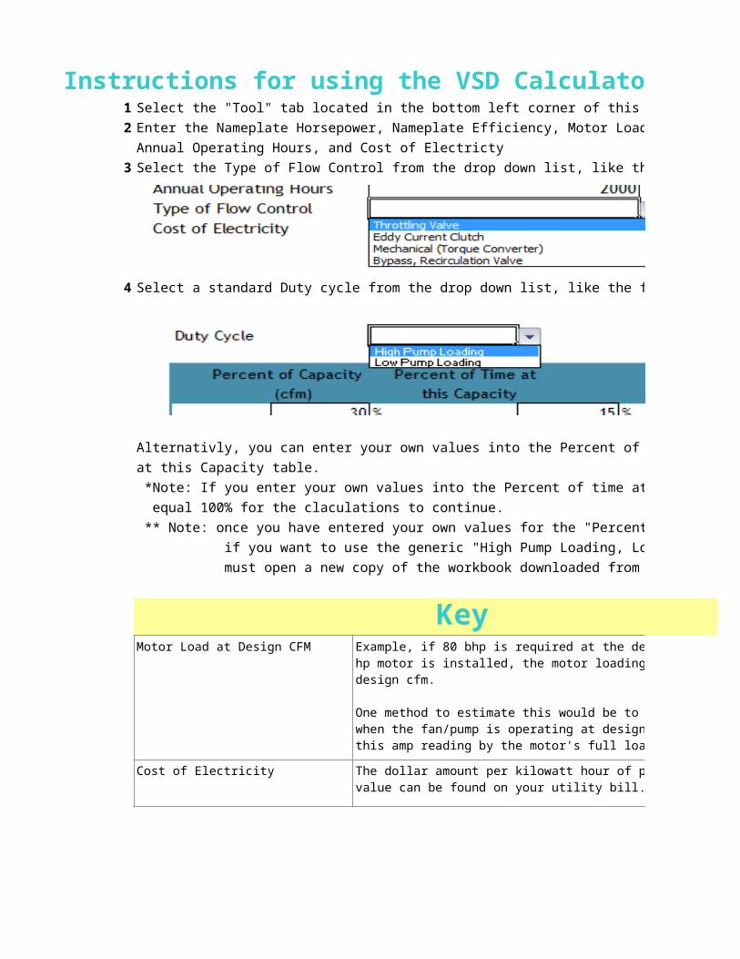
Instructions for using the VSD Calculator for Pumps Tool1 Select the "Tool" tab located in the bottom left corner of this window highlighted in red.
2 Enter the Nameplate Horsepower, Nameplate Efficiency, Motor Load at Pump Design GPM,
Annual Operating Hours, and Cost of Electricty
3 Select the Type of Flow Control from the drop down list, like the following:
4 Select a standard Duty cycle from the drop down list, like the following:
Alternativly, you can enter your own values into the Percent of Capacity and Percent of time
at this Capacity table.
*Note: If you enter your own values into the Percent of time at this Capacity table, they must
equal 100% for the claculations to continue.
** Note: once you have entered your own values for the "Percent of Time at this Capacity",
if you want to use the generic "High Pump Loading, Low Pump Loading", you
must open a new copy of the workbook downloaded from the wesite.
KeyMotor Load at Design CFM
Cost of Electricity
Duty Cycle
Example, if 80 bhp is required at the design cfm and a 100 hp motor is installed, the motor loading is 80% at pump design cfm.
One method to estimate this would be to take an Amp reading when the fan/pump is operating at design cfm and divide this amp reading by the motor's full load amp value.
The dollar amount per kilowatt hour of power consumed. This value can be found on your utility bill.
The percent of time that the pump spends in an active state. Selecting high and low will populate the table below with standard system specifications. The values in the table are editable. The "low load" duty cycle offers greater ASD energy savings potential than the "high load" duty cycle.

Percent of Capacity This is the estimated percentage of the pump’s design flowrate in cubic feet per minute.
Percent of time at this capacity
This is the estimated percentage of the year that the pump is expected to operate at the flowrate specified in the adjacent column.
Instructions for using the VSD Calculator for Pumps ToolSelect the "Tool" tab located in the bottom left corner of this window highlighted in red.
Enter the Nameplate Horsepower, Nameplate Efficiency, Motor Load at Pump Design GPM,
Select the Type of Flow Control from the drop down list, like the following:
Alternativly, you can enter your own values into the Percent of Capacity and Percent of time
*Note: If you enter your own values into the Percent of time at this Capacity table, they must
** Note: once you have entered your own values for the "Percent of Time at this Capacity",
if you want to use the generic "High Pump Loading, Low Pump Loading", you
must open a new copy of the workbook downloaded from the wesite.
KeyExample, if 80 bhp is required at the design cfm and a 100 hp motor is installed, the motor loading is 80% at pump
One method to estimate this would be to take an Amp reading when the fan/pump is operating at design cfm and divide this amp reading by the motor's full load amp value.
The dollar amount per kilowatt hour of power consumed. This value can be found on your utility bill.
The percent of time that the pump spends in an active state. Selecting high and low will populate the table below with standard system specifications. The values in the table are editable. The "low load" duty cycle offers greater ASD energy savings potential than the "high load" duty

This is the estimated percentage of the pump’s design
This is the estimated percentage of the year that the pump is expected to operate at the flowrate specified in the