vsphere resource management guide - vmware€¦ · this vsphere resource management guide is...
TRANSCRIPT
vSphere Resource Management GuideESX 4.0
ESXi 4.0vCenter Server 4.0
This document supports the version of each product listed andsupports all subsequent versions until the document is replacedby a new edition. To check for more recent editions of thisdocument, see http://www.vmware.com/support/pubs.
EN-000107-02

vSphere Resource Management Guide
2 VMware, Inc.
You can find the most up-to-date technical documentation on the VMware Web site at:
http://www.vmware.com/support/
The VMware Web site also provides the latest product updates.
If you have comments about this documentation, submit your feedback to:
Copyright © 2006–2011 VMware, Inc. All rights reserved. This product is protected by U.S. and international copyright andintellectual property laws. VMware products are covered by one or more patents listed at http://www.vmware.com/go/patents.
VMware is a registered trademark or trademark of VMware, Inc. in the United States and/or other jurisdictions. All other marksand names mentioned herein may be trademarks of their respective companies.
VMware, Inc.3401 Hillview Ave.Palo Alto, CA 94304www.vmware.com
Contents
Updated Information 5
About This Book 7
1 Getting Started with Resource Management 9
What Is Resource Management? 9Configuring Resource Allocation Settings 10Viewing Resource Allocation Information 13Admission Control 16
2 Managing CPU Resources 17
CPU Virtualization Basics 17Administering CPU Resources 18
3 Managing Memory Resources 25
Memory Virtualization Basics 25Administering Memory Resources 28
4 Managing Resource Pools 37
Why Use Resource Pools? 38Create Resource Pools 39Add Virtual Machines to a Resource Pool 40Removing Virtual Machines from a Resource Pool 41Resource Pool Admission Control 41
5 Creating a DRS Cluster 45
Admission Control and Initial Placement 46Virtual Machine Migration 47DRS Cluster Prerequisites 49Create a DRS Cluster 50Set a Custom Automation Level for a Virtual Machine 51Disable DRS 51
6 Using DRS Clusters to Manage Resources 53
Using DRS Rules 53Adding Hosts to a Cluster 55Adding Virtual Machines to a Cluster 56Remove Hosts from a Cluster 56Removing Virtual Machines from a Cluster 57DRS Cluster Validity 58Managing Power Resources 62
VMware, Inc. 3

7 Viewing DRS Cluster Information 67
Viewing the Cluster Summary Tab 67Using the DRS Tab 69
8 Using NUMA Systems with ESX/ESXi 73
What is NUMA? 73How ESX/ESXi NUMA Scheduling Works 74VMware NUMA Optimization Algorithms and Settings 75Resource Management in NUMA Architectures 76Specifying NUMA Controls 77
A Performance Monitoring Utilities: resxtop and esxtop 81
Using the esxtop Utility 81Using the resxtop Utility 81Using esxtop or resxtop in Interactive Mode 82Using Batch Mode 96Using Replay Mode 97
B Advanced Attributes 99
Set Advanced Host Attributes 99Set Advanced Virtual Machine Attributes 101
Index 103
vSphere Resource Management Guide
4 VMware, Inc.

Updated Information
This vSphere Resource Management Guide is updated with each release of the product or when necessary.
This table provides the update history of the vSphere Resource Management Guide.
Revision Description
EN-000107-02 Included a point in “Multicore Processors,” on page 19 section.
EN-000107-01 Removed references to CPU.MachineClearThreshold since this advanced CPU attribute is not availablethrough the vSphere Client.
EN-000107-00 Initial release.
VMware, Inc. 5

vSphere Resource Management Guide
6 VMware, Inc.

About This Book
The vSphere Resource Management Guide describes resource management for VMware® ESX™, ESXi, andVMware vCenter™ Server environments.
This guide focuses on the following topics.
n Resource allocation and resource management concepts
n Virtual machine attributes and admission control
n Resource pools and how to manage them
n Clusters, VMware Distributed Resource Scheduler (DRS), VMware Distributed Power Management(DPM), and how to work with them
n Advanced resource management options
n Performance considerations
The vSphere Resource Management Guide covers ESX, ESXi, and vCenter Server.
Intended AudienceThis manual is for system administrators who want to understand how the system manages resources andhow they can customize the default behavior. It’s also essential for anyone who wants to understand and useresource pools, clusters, DRS, or VMware DPM.
This manual assumes you have a working knowledge of VMware ESX and VMware ESXi and of vCenterServer.
Document FeedbackVMware welcomes your suggestions for improving our documentation. If you have comments, send yourfeedback to [email protected].
vSphere DocumentationThe VMware vSphere™ documentation consists of the combined vCenter Server and ESX/ESXi documentationset.
VMware, Inc. 7

Technical Support and Education ResourcesThe following technical support resources are available to you. To access the current version of this book andother books, go to http://www.vmware.com/support/pubs.
Online and TelephoneSupport
To use online support to submit technical support requests, view your productand contract information, and register your products, go to http://www.vmware.com/support.
Customers with appropriate support contracts should use telephone supportfor the fastest response on priority 1 issues. Go to http://www.vmware.com/support/phone_support.html.
Support Offerings To find out how VMware support offerings can help meet your business needs,go to http://www.vmware.com/support/services.
VMware ProfessionalServices
VMware Education Services courses offer extensive hands-on labs, case studyexamples, and course materials designed to be used as on-the-job referencetools. Courses are available onsite, in the classroom, and live online. For onsitepilot programs and implementation best practices, VMware ConsultingServices provides offerings to help you assess, plan, build, and manage yourvirtual environment. To access information about education classes,certification programs, and consulting services, go to http://www.vmware.com/services.
vSphere Resource Management Guide
8 VMware, Inc.

Getting Started with ResourceManagement 1
To understand resource management, you must be aware of its components, its goals, and how best toimplement it in a cluster setting.
Resource allocation settings for a virtual machine (shares, reservation, and limit) are discussed, including howto set them and how to view them. Also, admission control, the process whereby resource allocation settingsare validated against existing resources is explained.
This chapter includes the following topics:
n “What Is Resource Management?,” on page 9
n “Configuring Resource Allocation Settings,” on page 10
n “Viewing Resource Allocation Information,” on page 13
n “Admission Control,” on page 16
What Is Resource Management?Resource management is the allocation of resources from resource providers to resource consumers.
The need for resource management arises from the overcommitment of resources—that is, more demand thancapacity and from the fact that demand and capacity vary over time. Resource management allows you todynamically reallocate resources, so that you can more efficiently use available capacity.
Resource TypesResources include CPU, memory, power, storage, and network resources.
Resource management in this context focuses primarily on CPU and memory resources. Power resourceconsumption can also be reduced with the VMware® Distributed Power Management (DPM) feature.
NOTE ESX/ESXi manages network bandwidth and disk resources on a per-host basis, using network trafficshaping and a proportional share mechanism, respectively.
Resource ProvidersHosts and clusters are providers of physical resources.
For hosts, available resources are the host’s hardware specification, minus the resources used by thevirtualization software.
A cluster is a group of hosts. You can create a cluster using VMware® vCenter Server, and add multiple hoststo the cluster. vCenter Server manages these hosts’ resources jointly: the cluster owns all of the CPU andmemory of all hosts. You can enable the cluster for joint load balancing or failover. See Chapter 5, “Creating aDRS Cluster,” on page 45 for more information.
VMware, Inc. 9
Resource ConsumersVirtual machines are resource consumers.
The default resource settings assigned during creation work well for most machines. You can later edit thevirtual machine settings to allocate a share-based percentage of the total CPU and memory of the resourceprovider or a guaranteed reservation of CPU and memory. When you power on that virtual machine, the serverchecks whether enough unreserved resources are available and allows power on only if there are enoughresources. This process is called admission control.
A resource pool is a logical abstraction for flexible management of resources. Resource pools can be groupedinto hierarchies and used to hierarchically partition available CPU and memory resources. Accordingly,resource pools can be considered both resource providers and consumers. They provide resources to childresource pools and virtual machines, but are also resource consumers because they consume their parents’resources. See Chapter 4, “Managing Resource Pools,” on page 37.
An ESX/ESXi host allocates each virtual machine a portion of the underlying hardware resources based on anumber of factors:
n Total available resources for the ESX/ESXi host (or the cluster).
n Number of virtual machines powered on and resource usage by those virtual machines.
n Overhead required to manage the virtualization.
n Resource limits defined by the user.
Goals of Resource ManagementWhen managing your resources, you should be aware of what your goals are.
In addition to resolving resource overcommitment, resource management can help you accomplish thefollowing:
n Performance Isolation—prevent virtual machines from monopolizing resources and guaranteepredictable service rates.
n Efficient Utilization—exploit undercommitted resources and overcommit with graceful degradation.
n Easy Administration—control the relative importance of virtual machines, provide flexible dynamicpartitioning, and meet absolute service-level agreements.
Configuring Resource Allocation SettingsWhen available resource capacity does not meet the demands of the resource consumers (and virtualizationoverhead), administrators might need to customize the amount of resources that are allocated to virtualmachines or to the resource pools in which they reside.
Use the resource allocation settings (shares, reservation, and limit) to determine the amount of CPU andmemory resources provided for a virtual machine. In particular, administrators have several options forallocating resources.
n Reserve the physical resources of the host or cluster.
n Ensure that a certain amount of memory for a virtual machine is provided by the physical memory of theESX/ESXi machine.
n Guarantee that a particular virtual machine is always allocated a higher percentage of the physicalresources than other virtual machines.
n Set an upper bound on the resources that can be allocated to a virtual machine.
vSphere Resource Management Guide
10 VMware, Inc.
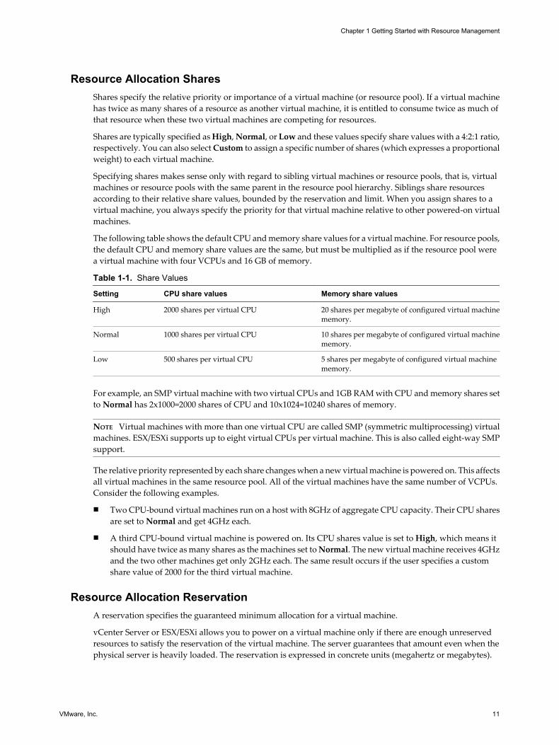
Resource Allocation SharesShares specify the relative priority or importance of a virtual machine (or resource pool). If a virtual machinehas twice as many shares of a resource as another virtual machine, it is entitled to consume twice as much ofthat resource when these two virtual machines are competing for resources.
Shares are typically specified as High, Normal, or Low and these values specify share values with a 4:2:1 ratio,respectively. You can also select Custom to assign a specific number of shares (which expresses a proportionalweight) to each virtual machine.
Specifying shares makes sense only with regard to sibling virtual machines or resource pools, that is, virtualmachines or resource pools with the same parent in the resource pool hierarchy. Siblings share resourcesaccording to their relative share values, bounded by the reservation and limit. When you assign shares to avirtual machine, you always specify the priority for that virtual machine relative to other powered-on virtualmachines.
The following table shows the default CPU and memory share values for a virtual machine. For resource pools,the default CPU and memory share values are the same, but must be multiplied as if the resource pool werea virtual machine with four VCPUs and 16 GB of memory.
Table 1-1. Share Values
Setting CPU share values Memory share values
High 2000 shares per virtual CPU 20 shares per megabyte of configured virtual machinememory.
Normal 1000 shares per virtual CPU 10 shares per megabyte of configured virtual machinememory.
Low 500 shares per virtual CPU 5 shares per megabyte of configured virtual machinememory.
For example, an SMP virtual machine with two virtual CPUs and 1GB RAM with CPU and memory shares setto Normal has 2x1000=2000 shares of CPU and 10x1024=10240 shares of memory.
NOTE Virtual machines with more than one virtual CPU are called SMP (symmetric multiprocessing) virtualmachines. ESX/ESXi supports up to eight virtual CPUs per virtual machine. This is also called eight-way SMPsupport.
The relative priority represented by each share changes when a new virtual machine is powered on. This affectsall virtual machines in the same resource pool. All of the virtual machines have the same number of VCPUs.Consider the following examples.
n Two CPU-bound virtual machines run on a host with 8GHz of aggregate CPU capacity. Their CPU sharesare set to Normal and get 4GHz each.
n A third CPU-bound virtual machine is powered on. Its CPU shares value is set to High, which means itshould have twice as many shares as the machines set to Normal. The new virtual machine receives 4GHzand the two other machines get only 2GHz each. The same result occurs if the user specifies a customshare value of 2000 for the third virtual machine.
Resource Allocation ReservationA reservation specifies the guaranteed minimum allocation for a virtual machine.
vCenter Server or ESX/ESXi allows you to power on a virtual machine only if there are enough unreservedresources to satisfy the reservation of the virtual machine. The server guarantees that amount even when thephysical server is heavily loaded. The reservation is expressed in concrete units (megahertz or megabytes).
Chapter 1 Getting Started with Resource Management
VMware, Inc. 11

For example, assume you have 2GHz available and specify a reservation of 1GHz for VM1 and 1GHz for VM2.Now each virtual machine is guaranteed to get 1GHz if it needs it. However, if VM1 is using only 500MHz,VM2 can use 1.5GHz.
Reservation defaults to 0. You can specify a reservation if you need to guarantee that the minimum requiredamounts of CPU or memory are always available for the virtual machine.
Resource Allocation LimitLimit specifies an upper bound for CPU or memory resources that can be allocated to a virtual machine.
A server can allocate more than the reservation to a virtual machine, but never allocates more than the limit,even if there is unutilized CPU or memory on the system. The limit is expressed in concrete units (megahertzor megabytes).
CPU and memory limit default to unlimited. When the memory limit is unlimited, the amount of memoryconfigured for the virtual machine when it was created becomes its effective limit in most cases.
In most cases, it is not necessary to specify a limit. There are benefits and drawbacks:
n Benefits — Assigning a limit is useful if you start with a small number of virtual machines and want tomanage user expectations. Performance deteriorates as you add more virtual machines. You can simulatehaving fewer resources available by specifying a limit.
n Drawbacks — You might waste idle resources if you specify a limit. The system does not allow virtualmachines to use more resources than the limit, even when the system is underutilized and idle resourcesare available. Specify the limit only if you have good reasons for doing so.
Resource Allocation Settings SuggestionsSelect resource allocation settings (shares, reservation, and limit) that are appropriate for your ESX/ESXienvironment.
The following guidelines can help you achieve better performance for your virtual machines.
n If you expect frequent changes to the total available resources, use Shares to allocate resources fairly acrossvirtual machines. If you use Shares, and you upgrade the host, for example, each virtual machine staysat the same priority (keeps the same number of shares) even though each share represents a larger amountof memory or CPU.
n Use Reservation to specify the minimum acceptable amount of CPU or memory, not the amount you wantto have available. The host assigns additional resources as available based on the number of shares,estimated demand, and the limit for your virtual machine. The amount of concrete resources representedby a reservation does not change when you change the environment, such as by adding or removingvirtual machines.
n When specifying the reservations for virtual machines, do not commit all resources (plan to leave at least10% unreserved.) As you move closer to fully reserving all capacity in the system, it becomes increasinglydifficult to make changes to reservations and to the resource pool hierarchy without violating admissioncontrol. In a DRS-enabled cluster, reservations that fully commit the capacity of the cluster or of individualhosts in the cluster can prevent DRS from migrating virtual machines between hosts.
Changing Resource Allocation Settings—ExampleThe following example illustrates how you can change resource allocation settings to improve virtual machineperformance.
Assume that on an ESX/ESXi host, you have created two new virtual machines—one each for your QA (VM-QA) and Marketing (VM-Marketing) departments.
vSphere Resource Management Guide
12 VMware, Inc.

Figure 1-1. Single Host with Two Virtual Machines
VM-QA
ESX/ESXihost
VM-Marketing
In the following example, assume that VM-QA is memory intensive and accordingly you want to change theresource allocation settings for the two virtual machines to:
n Specify that, when system memory is overcommitted, VM-QA can use twice as much memory and CPUas the Marketing virtual machine. Set the memory shares and CPU shares for VM-QA to High and forVM-Marketing set them to Normal.
n Ensure that the Marketing virtual machine has a certain amount of guaranteed CPU resources. You cando so using a reservation setting.
Procedure
1 Start the vSphere Client and connect to a vCenter Server.
2 Right-click VM-QA, the virtual machine for which you want to change shares, and select Edit Settings.
3 Select the Resources and In the CPU panel, select High from the Shares drop-down menu.
4 In the Memory panel, select High from the Shares drop-down menu.
5 Click OK.
6 Right-click the marketing virtual machine (VM-Marketing) and select Edit Settings.
7 In the CPU panel, change the value in the Reservation field to the desired number.
8 Click OK.
If you select the cluster’s Resource Allocation tab and click CPU, you should see that shares for VM-QA aretwice that of the other virtual machine. Also, because the virtual machines have not been powered on, theReservation Used fields have not changed.
Viewing Resource Allocation InformationUsing the vSphere Client, you can select a cluster, resource pool, standalone host, or a virtual machine in theinventory panel and view how its resources are being allocated by clicking the Resource Allocation tab.
This information can then be used to help inform your resource management decisions.
Cluster Resource Allocation TabThe Resource Allocation tab is available when you select a cluster from the inventory panel.
The Resource Allocation tab displays information about the CPU and memory resources in the cluster.
CPU SectionThe following information about CPU resource allocation is shown:
Chapter 1 Getting Started with Resource Management
VMware, Inc. 13
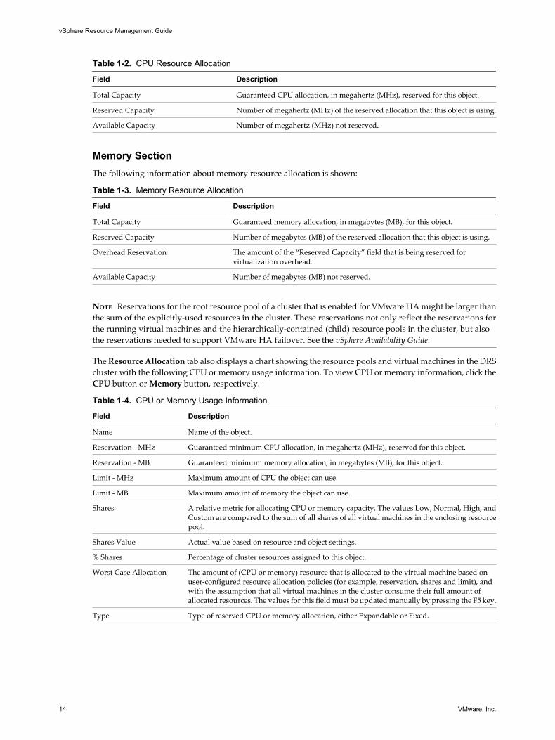
Table 1-2. CPU Resource Allocation
Field Description
Total Capacity Guaranteed CPU allocation, in megahertz (MHz), reserved for this object.
Reserved Capacity Number of megahertz (MHz) of the reserved allocation that this object is using.
Available Capacity Number of megahertz (MHz) not reserved.
Memory SectionThe following information about memory resource allocation is shown:
Table 1-3. Memory Resource Allocation
Field Description
Total Capacity Guaranteed memory allocation, in megabytes (MB), for this object.
Reserved Capacity Number of megabytes (MB) of the reserved allocation that this object is using.
Overhead Reservation The amount of the “Reserved Capacity” field that is being reserved forvirtualization overhead.
Available Capacity Number of megabytes (MB) not reserved.
NOTE Reservations for the root resource pool of a cluster that is enabled for VMware HA might be larger thanthe sum of the explicitly-used resources in the cluster. These reservations not only reflect the reservations forthe running virtual machines and the hierarchically-contained (child) resource pools in the cluster, but alsothe reservations needed to support VMware HA failover. See the vSphere Availability Guide.
The Resource Allocation tab also displays a chart showing the resource pools and virtual machines in the DRScluster with the following CPU or memory usage information. To view CPU or memory information, click theCPU button or Memory button, respectively.
Table 1-4. CPU or Memory Usage Information
Field Description
Name Name of the object.
Reservation - MHz Guaranteed minimum CPU allocation, in megahertz (MHz), reserved for this object.
Reservation - MB Guaranteed minimum memory allocation, in megabytes (MB), for this object.
Limit - MHz Maximum amount of CPU the object can use.
Limit - MB Maximum amount of memory the object can use.
Shares A relative metric for allocating CPU or memory capacity. The values Low, Normal, High, andCustom are compared to the sum of all shares of all virtual machines in the enclosing resourcepool.
Shares Value Actual value based on resource and object settings.
% Shares Percentage of cluster resources assigned to this object.
Worst Case Allocation The amount of (CPU or memory) resource that is allocated to the virtual machine based onuser-configured resource allocation policies (for example, reservation, shares and limit), andwith the assumption that all virtual machines in the cluster consume their full amount ofallocated resources. The values for this field must be updated manually by pressing the F5 key.
Type Type of reserved CPU or memory allocation, either Expandable or Fixed.
vSphere Resource Management Guide
14 VMware, Inc.

Virtual Machine Resource Allocation TabA Resource Allocation tab is available when you select a virtual machine from the inventory panel.
This Resource Allocation tab displays information about the CPU and memory resources for the selectedvirtual machine.
CPU SectionThese bars display the following information about host CPU usage:
Table 1-5. Host CPU
Field Description
Consumed Actual consumption of CPU resources by the virtual machine.
Active Estimated amount of resources consumed by virtual machine if there is no resource contention. Ifyou have set an explicit limit, this amount does not exceed that limit.
Table 1-6. Resource Settings
Field Description
Reservation Guaranteed minimum CPU allocation for this virtual machine.
Limit Maximum CPU allocation for this virtual machine.
Shares CPU shares for this virtual machine.
Worst CaseAllocation
The amount of (CPU or memory) resource that is allocated to the virtual machine based on user-configured resource allocation policies (for example, reservation, shares and limit), and with theassumption that all virtual machines in the cluster consume their full amount of allocated resources.
Memory SectionThese bars display the following information about host memory usage:
Table 1-7. Host Memory
Field Description
Consumed Actual consumption of physical memory that has been allocated to the virtual machine.
Overhead Consumption Amount of consumed memory being used for virtualization purposes. Overhead Consumptionis included in the amount shown in Consumed.
These bars display the following information about guest memory usage:
Table 1-8. Guest Memory
Field Description
Private Amount of memory backed by host memory and not being shared.
Shared Amount of memory being shared.
Swapped Amount of memory reclaimed by swapping.
Ballooned Amount of memory reclaimed by ballooning.
Unaccessed Amount of memory never referenced by the guest.
Active Amount of memory recently accessed.
Chapter 1 Getting Started with Resource Management
VMware, Inc. 15

Table 1-9. Resource Settings
Field Description
Reservation Guaranteed memory allocation for this virtual machine.
Limit Upper limit for this virtual machine’s memory allocation.
Shares Memory shares for this virtual machine.
Configured User-specified guest physical memory size.
Worst CaseAllocation
The amount of (CPU or memory) resource that is allocated to the virtual machine based on user-configured resource allocation policies (for example, reservation, shares and limit), and with theassumption that all virtual machines in the cluster consume their full amount of allocated resources.
OverheadReservation
The amount of memory that is being reserved for virtualization overhead.
Admission ControlWhen you power on a virtual machine, the system checks the amount of CPU and memory resources that havenot yet been reserved. Based on the available unreserved resources, the system determines whether it canguarantee the reservation for which the virtual machine is configured (if any). This process is called admissioncontrol.
If enough unreserved CPU and memory are available, or if there is no reservation, the virtual machine ispowered on. Otherwise, an Insufficient Resources warning appears.
NOTE In addition to the user-specified memory reservation, for each virtual machine there is also an amountof overhead memory. This extra memory commitment is included in the admission control calculation.
When the VMware DPM feature is enabled, hosts might be placed in standby mode (that is, powered off) toreduce power consumption. The unreserved resources provided by these hosts are considered available foradmission control. If a virtual machine cannot be powered on without these resources, a recommendation topower on sufficient standby hosts is made.
vSphere Resource Management Guide
16 VMware, Inc.

Managing CPU Resources 2ESX/ESXi hosts support CPU virtualization.
When you utilize CPU virtualization, you should understand how it works, its different types, and processor-specific behavior. Also, you need to be aware of the performance implications of CPU virtualization.
This chapter includes the following topics:
n “CPU Virtualization Basics,” on page 17
n “Administering CPU Resources,” on page 18
CPU Virtualization BasicsCPU virtualization emphasizes performance and runs directly on the processor whenever possible. Theunderlying physical resources are used whenever possible and the virtualization layer runs instructions onlyas needed to make virtual machines operate as if they were running directly on a physical machine.
CPU virtualization is not the same thing as emulation. With emulation, all operations are run in software byan emulator. A software emulator allows programs to run on a computer system other than the one for whichthey were originally written. The emulator does this by emulating, or reproducing, the original computer’sbehavior by accepting the same data or inputs and achieving the same results. Emulation provides portabilityand runs software designed for one platform across several platforms.
When CPU resources are overcommitted, the ESX/ESXi host time-slices the physical processors across allvirtual machines so each virtual machine runs as if it has its specified number of virtual processors. When anESX/ESXi host runs multiple virtual machines, it allocates to each virtual machine a share of the physicalresources. With the default resource allocation settings, all virtual machines associated with the same hostreceive an equal share of CPU per virtual CPU. This means that a single-processor virtual machines is assignedonly half of the resources of a dual-processor virtual machine.
Software-Based CPU VirtualizationWith software-based CPU virtualization, the guest application code runs directly on the processor, while theguest privileged code is translated and the translated code executes on the processor.
The translated code is slightly larger and usually executes more slowly than the native version. As a result,guest programs, which have a small privileged code component, run with speeds very close to native. Programswith a significant privileged code component, such as system calls, traps, or page table updates can run slowerin the virtualized environment.
VMware, Inc. 17

Hardware-Assisted CPU VirtualizationCertain processors (such as Intel VT and AMD SVM) provide hardware assistance for CPU virtualization.
When using this assistance, the guest can use a separate mode of execution called guest mode. The guest code,whether application code or privileged code, runs in the guest mode. On certain events, the processor exitsout of guest mode and enters root mode. The hypervisor executes in the root mode, determines the reason forthe exit, takes any required actions, and restarts the guest in guest mode.
When you use hardware assistance for virtualization, there is no need to translate the code. As a result, systemcalls or trap-intensive workloads run very close to native speed. Some workloads, such as those involvingupdates to page tables, lead to a large number of exits from guest mode to root mode. Depending on the numberof such exits and total time spent in exits, this can slow down execution significantly.
Virtualization and Processor-Specific BehaviorAlthough VMware software virtualizes the CPU, the virtual machine detects the specific model of the processoron which it is running.
Processor models might differ in the CPU features they offer, and applications running in the virtual machinecan make use of these features. Therefore, it is not possible to use VMotion® to migrate virtual machinesbetween systems running on processors with different feature sets. You can avoid this restriction, in somecases, by using Enhanced VMotion Compatibility (EVC) with processors that support this feature. See BasicSystem Administration for more information.
Performance Implications of CPU VirtualizationCPU virtualization adds varying amounts of overhead depending on the workload and the type ofvirtualization used.
An application is CPU-bound if it spends most of its time executing instructions rather than waiting for externalevents such as user interaction, device input, or data retrieval. For such applications, the CPU virtualizationoverhead includes the additional instructions that must be executed. This overhead takes CPU processing timethat the application itself can use. CPU virtualization overhead usually translates into a reduction in overallperformance.
For applications that are not CPU-bound, CPU virtualization likely translates into an increase in CPU use. Ifspare CPU capacity is available to absorb the overhead, it can still deliver comparable performance in termsof overall throughput.
ESX/ESXi supports up to eight virtual processors (CPUs) for each virtual machine.
NOTE Deploy single-threaded applications on uniprocessor virtual machines, instead of on SMP virtualmachines, for the best performance and resource use.
Single-threaded applications can take advantage only of a single CPU. Deploying such applications in dual-processor virtual machines does not speed up the application. Instead, it causes the second virtual CPU to usephysical resources that other virtual machines could otherwise use.
Administering CPU ResourcesYou can configure virtual machines with one or more virtual processors, each with its own set of registers andcontrol structures.
When a virtual machine is scheduled, its virtual processors are scheduled to run on physical processors. TheVMkernel Resource Manager schedules the virtual CPUs on physical CPUs, thereby managing the virtualmachine’s access to physical CPU resources. ESX/ESXi supports virtual machines with up to eight virtualprocessors.
vSphere Resource Management Guide
18 VMware, Inc.

View Processor InformationYou can access information about current CPU configuration through the vSphere Client or using the vSphereSDK.
Procedure
1 In the vSphere Client, select the host and click the Configuration tab.
2 Select Processors.
You can view the information about the number and type of physical processors and the number of logicalprocessors.
NOTE In hyperthreaded systems, each hardware thread is a logical processor. For example, a dual-coreprocessor with hyperthreading enabled has two cores and four logical processors.
3 (Optional) You can also disable or enable hyperthreading by clicking Properties.
Specifying CPU ConfigurationYou can specify CPU configuration to improve resource management. However, if you do not customize CPUconfiguration, the ESX/ESXi host uses defaults that work well in most situations.
You can specify CPU configuration in the following ways:
n Use the attributes and special features available through the vSphere Client. The vSphere Client graphicaluser interface (GUI) allows you to connect to an ESX/ESXi host or a vCenter Server system.
n Use advanced settings under certain circumstances.
n Use the vSphere SDK for scripted CPU allocation.
n Use hyperthreading.
Multicore ProcessorsMulticore processors provide many advantages for an ESX/ESXi host performing multitasking of virtualmachines.
Intel and AMD have each developed processors which combine two or more processor cores into a singleintegrated circuit (often called a package or socket). VMware uses the term socket to describe a single packagewhich can have one or more processor cores with one or more logical processors in each core.
A dual-core processor, for example, can provide almost double the performance of a single-core processor, byallowing two virtual CPUs to execute at the same time. Cores within the same processor are typicallyconfigured with a shared last-level cache used by all cores, potentially reducing the need to access slower mainmemory. A shared memory bus that connects a physical processor to main memory can limit performance ofits logical processors if the virtual machines running on them are running memory-intensive workloads whichcompete for the same memory bus resources.
Each logical processor of each processor core can be used independently by the ESX CPU scheduler to executevirtual machines, providing capabilities similar to SMP systems. For example, a two-way virtual machine canhave its virtual processors running on logical processors that belong to the same core, or on logical processorson different physical cores.
The ESX CPU scheduler can detect the processor topology and the relationships between processor cores andthe logical processors on them. It uses this information to schedule virtual machines and optimize performance.
Chapter 2 Managing CPU Resources
VMware, Inc. 19

The ESX CPU scheduler can interpret processor topology, including the relationship between sockets, cores,and logical processors. The scheduler uses topology information to optimize the placement of virtual CPUsonto different sockets to maximize overall cache utilization, and to improve cache affinity by minimizingvirtual CPU migrations.
In undercommitted systems, the ESX CPU scheduler spreads load across all sockets by default. This improvesperformance by maximizing the aggregate amount of cache available to the running virtual CPUs. As a result,the virtual CPUs of a single SMP virtual machine are spread across multiple sockets (unless each socket is alsoa NUMA node, in which case the NUMA scheduler restricts all the virtual CPUs of the virtual machine toreside on the same socket.)
In some cases, such as when an SMP virtual machine exhibits significant data sharing between its virtual CPUs,this default behavior might be sub-optimal. For such workloads, it can be beneficial to schedule all of the virtualCPUs on the same socket, with a shared last-level cache, even when the ESX/ESXi host is undercommitted. Insuch scenarios, you can override the default behavior of spreading virtual CPUs across packages by includingthe following configuration option in the virtual machine's .vmx configuration file:sched.cpu.vsmpConsolidate="TRUE".
To find out if a change in this parameter helps with performance, please do proper load testing. You cannoteasily predict the effect of a change in this parameter. If you do not see a performance boost after changing theparameter, you have to revert the parameter to its default value.
HyperthreadingHyperthreading technology allows a single physical processor core to behave like two logical processors. Theprocessor can run two independent applications at the same time. To avoid confusion between logical andphysical processors, Intel refers to a physical processor as a socket, and the discussion in this chapter uses thatterminology as well.
Intel Corporation developed hyperthreading technology to enhance the performance of its Pentium IV andXeon processor lines. Hyperthreading technology allows a single processor core to execute two independentthreads simultaneously.
While hyperthreading does not double the performance of a system, it can increase performance by betterutilizing idle resources leading to greater throughput for certain important workload types. An applicationrunning on one logical processor of a busy core can expect slightly more than half of the throughput that itobtains while running alone on a non-hyperthreaded processor. Hyperthreading performance improvementsare highly application-dependent, and some applications might see performance degradation withhyperthreading because many processor resources (such as the cache) are shared between logical processors.
NOTE On processors with Intel Hyper-Threading technology, each core can have two logical processors whichshare most of the core's resources, such as memory caches and functional units. Such logical processors areusually called threads.
Many processors do not support hyperthreading and as a result have only one thread per core. For suchprocessors, the number of cores also matches the number of logical processors. The following processorssupport hyperthreading and have two threads per core.
n Processors based on the Intel Xeon 5500 processor microarchitecture.
n Intel Pentium 4 (HT-enabled)
n Intel Pentium EE 840 (HT-enabled)
vSphere Resource Management Guide
20 VMware, Inc.
Hyperthreading and ESX/ESXi HostsAn ESX/ESXi host enabled for hyperthreading should behave similarly to a host without hyperthreading. Youmight need to consider certain factors if you enable hyperthreading, however.
ESX/ESXi hosts manage processor time intelligently to guarantee that load is spread smoothly across processorcores in the system. Logical processors on the same core have consecutive CPU numbers, so that CPUs 0 and1 are on the first core together, CPUs 2 and 3 are on the second core, and so on. Virtual machines arepreferentially scheduled on two different cores rather than on two logical processors on the same core.
If there is no work for a logical processor, it is put into a halted state, which frees its execution resources andallows the virtual machine running on the other logical processor on the same core to use the full executionresources of the core. The VMware scheduler properly accounts for this halt time, and charges a virtual machinerunning with the full resources of a core more than a virtual machine running on a half core. This approach toprocessor management ensures that the server does not violate any of the standard ESX/ESXi resourceallocation rules.
Consider your resource management needs before you enable CPU affinity on hosts using hyperthreading.For example, if you bind a high priority virtual machine to CPU 0 and another high priority virtual machineto CPU 1, the two virtual machines have to share the same physical core. In this case, it can be impossible tomeet the resource demands of these virtual machines. Ensure that any custom affinity settings make sense fora hyperthreaded system.
Enable HyperthreadingTo enable hyperthreading you must first enable it in your system's BIOS settings and then turn it on in thevSphere Client. Hyperthreading is enabled by default.
Some Intel processors, for example Xeon 5500 processors or those based on the P4 microarchitecture, supporthyperthreading. Consult your system documentation to determine whether your CPU supportshyperthreading. ESX/ESXi cannot enable hyperthreading on a system with more than 32 physical cores,because ESX/ESXi has a logical limit of 64 CPUs.
Procedure
1 Ensure that your system supports hyperthreading technology.
2 Enable hyperthreading in the system BIOS.
Some manufacturers label this option Logical Processor, while others call it Enable Hyperthreading.
3 Make sure that you turn on hyperthreading for your ESX/ESXi host.
a In the vSphere Client, select the host and click the Configuration tab.
b Select Processors and click Properties.
c In the dialog box, you can view hyperthreading status and turn hyperthreading off or on (default).
Hyperthreading is now enabled.
Set Hyperthreading Sharing Options for a Virtual MachineYou can specify how the virtual CPUs of a virtual machine can share physical cores on a hyperthreaded system.
Two virtual CPUs share a core if they are running on logical CPUs of the core at the same time. You can setthis for individual virtual machines.
Procedure
1 In the vSphere Client inventory panel, right-click the virtual machine and select Edit Settings.
2 Click the Resources tab, and click Advanced CPU.
Chapter 2 Managing CPU Resources
VMware, Inc. 21
3 Select a hyperthreading mode for this virtual machine from the Mode drop-down menu.
Hyperthreaded Core Sharing Options
You can set the hyperthreaded core sharing mode for a virtual machine using the vSphere Client.
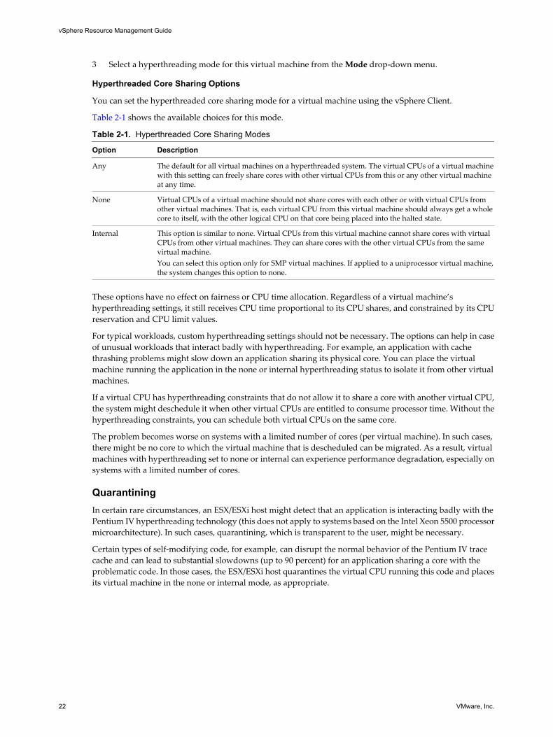
Table 2-1 shows the available choices for this mode.
Table 2-1. Hyperthreaded Core Sharing Modes
Option Description
Any The default for all virtual machines on a hyperthreaded system. The virtual CPUs of a virtual machinewith this setting can freely share cores with other virtual CPUs from this or any other virtual machineat any time.
None Virtual CPUs of a virtual machine should not share cores with each other or with virtual CPUs fromother virtual machines. That is, each virtual CPU from this virtual machine should always get a wholecore to itself, with the other logical CPU on that core being placed into the halted state.
Internal This option is similar to none. Virtual CPUs from this virtual machine cannot share cores with virtualCPUs from other virtual machines. They can share cores with the other virtual CPUs from the samevirtual machine.You can select this option only for SMP virtual machines. If applied to a uniprocessor virtual machine,the system changes this option to none.
These options have no effect on fairness or CPU time allocation. Regardless of a virtual machine’shyperthreading settings, it still receives CPU time proportional to its CPU shares, and constrained by its CPUreservation and CPU limit values.
For typical workloads, custom hyperthreading settings should not be necessary. The options can help in caseof unusual workloads that interact badly with hyperthreading. For example, an application with cachethrashing problems might slow down an application sharing its physical core. You can place the virtualmachine running the application in the none or internal hyperthreading status to isolate it from other virtualmachines.
If a virtual CPU has hyperthreading constraints that do not allow it to share a core with another virtual CPU,the system might deschedule it when other virtual CPUs are entitled to consume processor time. Without thehyperthreading constraints, you can schedule both virtual CPUs on the same core.
The problem becomes worse on systems with a limited number of cores (per virtual machine). In such cases,there might be no core to which the virtual machine that is descheduled can be migrated. As a result, virtualmachines with hyperthreading set to none or internal can experience performance degradation, especially onsystems with a limited number of cores.
QuarantiningIn certain rare circumstances, an ESX/ESXi host might detect that an application is interacting badly with thePentium IV hyperthreading technology (this does not apply to systems based on the Intel Xeon 5500 processormicroarchitecture). In such cases, quarantining, which is transparent to the user, might be necessary.
Certain types of self-modifying code, for example, can disrupt the normal behavior of the Pentium IV tracecache and can lead to substantial slowdowns (up to 90 percent) for an application sharing a core with theproblematic code. In those cases, the ESX/ESXi host quarantines the virtual CPU running this code and placesits virtual machine in the none or internal mode, as appropriate.
vSphere Resource Management Guide
22 VMware, Inc.
Using CPU AffinityBy specifying a CPU affinity setting for each virtual machine, you can restrict the assignment of virtualmachines to a subset of the available processors in multiprocessor systems. By using this feature, you can assigneach virtual machine to processors in the specified affinity set.
In this context, the term CPU refers to a logical processor on a hyperthreaded system, but refers to a core on anon-hyperthreaded system.
The CPU affinity setting for a virtual machine applies not only to all of the virtual CPUs associated with thevirtual machine, but also to all other threads (also known as worlds) associated with the virtual machine. Suchvirtual machine threads perform processing required for emulating mouse, keyboard, screen, CD-ROM andmiscellaneous legacy devices.
In some cases, such as display-intensive workloads, significant communication might occur between the virtualCPUs and these other virtual machine threads. Performance might degrade if the virtual machine's affinitysetting prevents these additional threads from being scheduled concurrently with the virtual machine's virtualCPUs (for example, a uniprocessor virtual machine with affinity to a single CPU, or a two-way SMP virtualmachine with affinity to only two CPUs).
For the best performance, when you use manual affinity settings, VMware recommends that you include atleast one additional physical CPU in the affinity setting to allow at least one of the virtual machine's threadsto be scheduled at the same time as its virtual CPUs (for example, a uniprocessor virtual machine with affinityto at least two CPUs or a two-way SMP virtual machine with affinity to at least three CPUs).
NOTE CPU affinity specifies virtual machine-to-processor placement constraints and is different from theaffinity based on DRS rules, which specifies virtual machine-to-virtual machine host placement constraints.
Assign a Virtual Machine to a Specific ProcessorUsing CPU affinity, you can assign a virtual machine to a specific processor. This allows you to restrict theassignment of virtual machines to a specific available processor in multiprocessor systems.
Procedure
1 In the vSphere Client inventory panel, select a virtual machine and select Edit Settings.
2 Select the Resources tab and select Advanced CPU.
3 Click the Run on processor(s) button.
4 Select the processors on which you want the virtual machine to run and click OK.
Potential Issues with CPU AffinityBefore you use CPU affinity, you might need to consider certain issues.
Potential issues with CPU affinity include:
n For multiprocessor systems, ESX/ESXi systems perform automatic load balancing. Avoid manualspecification of virtual machine affinity to improve the scheduler’s ability to balance load acrossprocessors.
n Affinity can interfere with the ESX/ESXi host’s ability to meet the reservation and shares specified for avirtual machine.
n Because CPU admission control does not consider affinity, a virtual machine with manual affinity settingsmight not always receive its full reservation.
Virtual machines that do not have manual affinity settings are not adversely affected by virtual machineswith manual affinity settings.
Chapter 2 Managing CPU Resources
VMware, Inc. 23

n When you move a virtual machine from one host to another, affinity might no longer apply because thenew host might have a different number of processors.
n The NUMA scheduler might not be able to manage a virtual machine that is already assigned to certainprocessors using affinity.
n Affinity can affect an ESX/ESXi host's ability to schedule virtual machines on multicore or hyperthreadedprocessors to take full advantage of resources shared on such processors.
CPU Power ManagementTo improve CPU power efficiency, you can configure your ESX/ESXi hosts to dynamically switch CPUfrequencies based on workload demands. This type of power management is called Dynamic Voltage andFrequency Scaling (DVFS). It uses processor performance states (P-states) made available to the VMkernelthrough an ACPI interface.
ESX/ESXi supports the Enhanced Intel SpeedStep and Enhanced AMD PowerNow! CPU power managementtechnologies. For the VMkernel to take advantage of the power management capabilities provided by thesetechnologies, you might need to first enable power management, sometimes referred to as Demand-BasedSwitching (DBS), in the BIOS.
To set the CPU power management policy, use the advanced host attribute Power.CpuPolicy. This attributesetting is saved in the host configuration and can be used again at boot time, but it can be changed at any timeand does not require a server reboot. You can set this attribute to the following values.
static The default. The VMkernel can detect power management features availableon the host but does not actively use them unless requested by the BIOS forpower capping or thermal events.
dynamic The VMkernel optimizes each CPU's frequency to match demand in order toimprove power efficiency but not affect performance. When CPU demandincreases, this policy setting ensures that CPU frequencies also increase.
vSphere Resource Management Guide
24 VMware, Inc.

Managing Memory Resources 3All modern operating systems provide support for virtual memory, allowing software to use more memorythan the machine physically has. Similarly, the ESX/ESXi hypervisor provides support for overcommittingvirtual machine memory, where the amount of guest memory configured for all virtual machines might belarger than the amount of physical host memory.
If you intend to use memory virtualization, you should understand how ESX/ESXi hosts allocate, tax, andreclaim memory. Also, you need to be aware of the memory overhead incurred by virtual machines.
This chapter includes the following topics:
n “Memory Virtualization Basics,” on page 25
n “Administering Memory Resources,” on page 28
Memory Virtualization BasicsBefore you manage memory resources, you should understand how they are being virtualized and used byESX/ESXi.
The VMkernel manages all machine memory. (An exception to this is the memory that is allocated to the serviceconsole in ESX.) The VMkernel dedicates part of this managed machine memory for its own use. The rest isavailable for use by virtual machines. Virtual machines use machine memory for two purposes: each virtualmachine requires its own memory and the VMM requires some memory and a dynamic overhead memory forits code and data.
The virtual memory space is divided into blocks, typically 4KB, called pages. The physical memory is alsodivided into blocks, also typically 4KB. When physical memory is full, the data for virtual pages that are notpresent in physical memory are stored on disk. ESX/ESXi also provides support for large pages (2 MB). See “Advanced Memory Attributes,” on page 100.
Virtual Machine MemoryEach virtual machine consumes memory based on its configured size, plus additional overhead memory forvirtualization.
Configured SizeThe configured size is a construct maintained by the virtualization layer for the virtual machine. It is the amountof memory that is presented to the guest operating system, but it is independent of the amount of physicalRAM that is allocated to the virtual machine, which depends on the resource settings (shares, reservation, limit)explained below.
VMware, Inc. 25
For example, consider a virtual machine with a configured size of 1GB. When the guest operating system boots,it detects that it is running on a dedicated machine with 1GB of physical memory. The actual amount of physicalhost memory allocated to the virtual machine depends on its memory resource settings and memory contentionon the ESX/ESXi host. In some cases, the virtual machine might be allocated the full 1GB. In other cases, itmight receive a smaller allocation. Regardless of the actual allocation, the guest operating system continues tobehave as though it is running on a dedicated machine with 1GB of physical memory.
Shares Specify the relative priority for a virtual machine if more than the reservationis available.
Reservation Is a guaranteed lower bound on the amount of physical memory that the hostreserves for the virtual machine, even when memory is overcommitted. Set thereservation to a level that ensures the virtual machine has sufficient memoryto run efficiently, without excessive paging.
After a virtual machine has accessed its full reservation, it is allowed to retainthat amount of memory and this memory is not reclaimed, even if the virtualmachine becomes idle. For example, some guest operating systems (forexample, Linux) might not access all of the configured memory immediatelyafter booting. Until the virtual machines accesses its full reservation, VMkernelcan allocate any unused portion of its reservation to other virtual machines.However, after the guest’s workload increases and it consumes its fullreservation, it is allowed to keep this memory.
Limit Is an upper bound on the amount of physical memory that the host can allocateto the virtual machine. The virtual machine’s memory allocation is alsoimplicitly limited by its configured size.
Overhead memory includes space reserved for the virtual machine framebuffer and various virtualization data structures.
Memory OvercommitmentFor each running virtual machine, the system reserves physical memory for the virtual machine’s reservation(if any) and for its virtualization overhead.
Because of the memory management techniques the ESX/ESXi host uses, your virtual machines can use morememory than the physical machine (the host) has available. For example, you can have a host with 2GB memoryand run four virtual machines with 1GB memory each. In that case, the memory is overcommitted.
Overcommitment makes sense because, typically, some virtual machines are lightly loaded while others aremore heavily loaded, and relative activity levels vary over time.
To improve memory utilization, the ESX/ESXi host transfers memory from idle virtual machines to virtualmachines that need more memory. Use the Reservation or Shares parameter to preferentially allocate memoryto important virtual machines. This memory remains available to other virtual machines if it is not in use.
Memory SharingMany workloads present opportunities for sharing memory across virtual machines.
For example, several virtual machines might be running instances of the same guest operating system, havethe same applications or components loaded, or contain common data. ESX/ESXi systems use a proprietarypage-sharing technique to securely eliminate redundant copies of memory pages.
With memory sharing, a workload consisting of multiple virtual machines often consumes less memory thanit would when running on physical machines. As a result, the system can efficiently support higher levels ofovercommitment.
vSphere Resource Management Guide
26 VMware, Inc.
The amount of memory saved by memory sharing depends on workload characteristics. A workload of manynearly identical virtual machines might free up more than thirty percent of memory, while a more diverseworkload might result in savings of less than five percent of memory.
Software-Based Memory VirtualizationESX/ESXi virtualizes guest physical memory by adding an extra level of address translation.
n The VMM for each virtual machine maintains a mapping from the guest operating system's physicalmemory pages to the physical memory pages on the underlying machine. (VMware refers to theunderlying host physical pages as “machine” pages and the guest operating system’s physical pages as“physical” pages.)
Each virtual machine sees a contiguous, zero-based, addressable physical memory space. The underlyingmachine memory on the server used by each virtual machine is not necessarily contiguous.
n The VMM intercepts virtual machine instructions that manipulate guest operating system memorymanagement structures so that the actual memory management unit (MMU) on the processor is notupdated directly by the virtual machine.
n The ESX/ESXi host maintains the virtual-to-machine page mappings in a shadow page table that is keptup to date with the physical-to-machine mappings (maintained by the VMM).
n The shadow page tables are used directly by the processor's paging hardware.
This approach to address translation allows normal memory accesses in the virtual machine to execute withoutadding address translation overhead, after the shadow page tables are set up. Because the translation look-aside buffer (TLB) on the processor caches direct virtual-to-machine mappings read from the shadow pagetables, no additional overhead is added by the VMM to access the memory.
Performance ConsiderationsThe use of two-page tables has these performance implications.
n No overhead is incurred for regular guest memory accesses.
n Additional time is required to map memory within a virtual machine, which might mean:
n The virtual machine operating system is setting up or updating virtual address to physical addressmappings.
n The virtual machine operating system is switching from one address space to another (context switch).
n Like CPU virtualization, memory virtualization overhead depends on workload.
Hardware-Assisted Memory VirtualizationSome CPUs, such as AMD SVM-V and the Intel Xeon 5500 series, provide hardware support for memoryvirtualization by using two layers of page tables.
The first layer of page tables stores guest virtual-to-physical translations, while the second layer of page tablesstores guest physical-to-machine translation. The TLB (translation look-aside buffer) is a cache of translationsmaintained by the processor's memory management unit (MMU) hardware. A TLB miss is a miss in this cacheand the hardware needs to go to memory (possibly many times) to find the required translation. For a TLBmiss to a certain guest virtual address, the hardware looks at both page tables to translate guest virtual addressto host physical address.
The diagram in Figure 3-1 illustrates the ESX/ESXi implementation of memory virtualization.
Chapter 3 Managing Memory Resources
VMware, Inc. 27
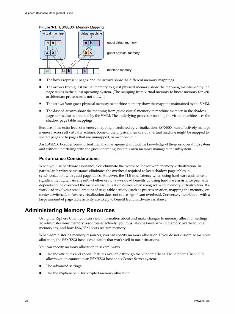
Figure 3-1. ESX/ESXi Memory Mapping
virtual machine1
guest virtual memory
guest physical memory
machine memory
a b
a
a b b c
b
c b
b c
virtual machine2
n The boxes represent pages, and the arrows show the different memory mappings.
n The arrows from guest virtual memory to guest physical memory show the mapping maintained by thepage tables in the guest operating system. (The mapping from virtual memory to linear memory for x86-architecture processors is not shown.)
n The arrows from guest physical memory to machine memory show the mapping maintained by the VMM.
n The dashed arrows show the mapping from guest virtual memory to machine memory in the shadowpage tables also maintained by the VMM. The underlying processor running the virtual machine uses theshadow page table mappings.
Because of the extra level of memory mapping introduced by virtualization, ESX/ESXi can effectively managememory across all virtual machines. Some of the physical memory of a virtual machine might be mapped toshared pages or to pages that are unmapped, or swapped out.
An ESX/ESXi host performs virtual memory management without the knowledge of the guest operating systemand without interfering with the guest operating system’s own memory management subsystem.
Performance ConsiderationsWhen you use hardware assistance, you eliminate the overhead for software memory virtualization. Inparticular, hardware assistance eliminates the overhead required to keep shadow page tables insynchronization with guest page tables. However, the TLB miss latency when using hardware assistance issignificantly higher. As a result, whether or not a workload benefits by using hardware assistance primarilydepends on the overhead the memory virtualization causes when using software memory virtualization. If aworkload involves a small amount of page table activity (such as process creation, mapping the memory, orcontext switches), software virtualization does not cause significant overhead. Conversely, workloads with alarge amount of page table activity are likely to benefit from hardware assistance.
Administering Memory ResourcesUsing the vSphere Client you can view information about and make changes to memory allocation settings.To administer your memory resources effectively, you must also be familiar with memory overhead, idlememory tax, and how ESX/ESXi hosts reclaim memory.
When administering memory resources, you can specify memory allocation. If you do not customize memoryallocation, the ESX/ESXi host uses defaults that work well in most situations.
You can specify memory allocation in several ways.
n Use the attributes and special features available through the vSphere Client. The vSphere Client GUIallows you to connect to an ESX/ESXi host or a vCenter Server system.
n Use advanced settings.
n Use the vSphere SDK for scripted memory allocation.
vSphere Resource Management Guide
28 VMware, Inc.
View Memory Allocation InformationYou can use the vSphere Client to view information about current memory allocations.
You can view the information about the total memory and memory available to virtual machines. In ESX, youcan also view memory assigned to the service console.
Procedure
1 In the vSphere Client, select a host and click the Configuration tab.
2 Click Memory.
You can view the information shown in “Host Memory Information,” on page 29.
Host Memory InformationThe vSphere Client shows information about host memory allocation.
The host memory fields are discussed in Table 3-1.
Table 3-1. Host Memory Information
Field Description
Total Total physical memory for this host.
System Memory used by the ESX/ESXi system.ESX/ESXi uses at least 50MB of system memory for the VMkernel, and additional memory fordevice drivers. This memory is allocated when the ESX/ESXi is loaded and is not configurable.The actual required memory for the virtualization layer depends on the number and type of PCI(peripheral component interconnect) devices on a host. Some drivers need 40MB, which almostdoubles base system memory.The ESX/ESXi host also attempts to keep some memory free at all times to handle dynamicallocation requests efficiently. ESX/ESXi sets this level at approximately six percent of thememory available for running virtual machines.An ESXi host uses additional system memory for management agents that run in the serviceconsole of an ESX host.
Virtual Machines Memory used by virtual machines running on the selected host.Most of the host’s memory is used for running virtual machines. An ESX/ESXi host manages theallocation of this memory to virtual machines based on administrative parameters and systemload.The amount of physical memory the virtual machines can use is always less than what is in thephysical host because the virtualization layer takes up some resources. For example, a host witha dual 3.2GHz CPU and 2GB of memory might make 6GHz of CPU power and 1.5GB of memoryavailable for use by virtual machines.
Service Console Memory reserved for the service console.Click Properties to change how much memory is available for the service console. This fieldappears only in ESX. ESXi does not provide a service console.
Understanding Memory OverheadVirtualization of memory resources has some associated overhead.
ESX/ESXi virtual machines can incur two kinds of memory overhead.
n The additional time to access memory within a virtual machine.
n The extra space needed by the ESX/ESXi host for its own code and data structures, beyond the memoryallocated to each virtual machine.
Chapter 3 Managing Memory Resources
VMware, Inc. 29

ESX/ESXi memory virtualization adds little time overhead to memory accesses. Because the processor's paginghardware uses page tables (shadow page tables for software-based approach or nested page tables forhardware-assisted approach) directly, most memory accesses in the virtual machine can execute withoutaddress translation overhead.
The memory space overhead has two components.
n A fixed, system-wide overhead for the VMkernel and (for ESX only) the service console.
n Additional overhead for each virtual machine.
For ESX, the service console typically uses 272MB and the VMkernel uses a smaller amount of memory. Theamount depends on the number and size of the device drivers that are being used.
Overhead memory includes space reserved for the virtual machine frame buffer and various virtualizationdata structures, such as shadow page tables. Overhead memory depends on the number of virtual CPUs andthe configured memory for the guest operating system.
ESX/ESXi also provides optimizations such as memory sharing to reduce the amount of physical memory usedon the underlying server. These optimizations can save more memory than is taken up by the overhead.
Overhead Memory on Virtual MachinesVirtual machines incur overhead memory. You should be aware of the amount of this overhead.
Table 3-2 lists the overhead memory (in MB) for each number of VCPUs.
Table 3-2. Overhead Memory on Virtual Machines
Memory(MB) 1 VCPU 2 VCPUs 3 VCPUs 4 VCPUs 5 VCPUs 6 VCPUs 7 VCPUs 8 VCPUs
256 113.17 159.43 200.53 241.62 293.15 334.27 375.38 416.50
512 116.68 164.96 206.07 247.17 302.75 343.88 385.02 426.15
1024 123.73 176.05 217.18 258.30 322.00 363.17 404.34 445.52
2048 137.81 198.20 239.37 280.53 360.46 401.70 442.94 484.18
4096 165.98 242.51 283.75 324.99 437.37 478.75 520.14 561.52
8192 222.30 331.12 372.52 413.91 591.20 632.86 674.53 716.19
16384 334.96 508.34 550.05 591.76 900.44 942.98 985.52 1028.07
32768 560.27 863.41 906.06 948.71 1515.75 1559.42 1603.09 1646.76
65536 1011.21 1572.29 1616.19 1660.09 2746.38 2792.30 2838.22 2884.14
131072 1912.48 2990.05 3036.46 3082.88 5220.24 5273.18 5326.11 5379.05
262144 3714.99 5830.60 5884.53 5938.46 10142.83 10204.79 10266.74 10328.69
How ESX/ESXi Hosts Allocate MemoryAn ESX/ESXi host allocates the memory specified by the Limit parameter to each virtual machine, unlessmemory is overcommitted. An ESX/ESXi host never allocates more memory to a virtual machine than itsspecified physical memory size.
For example, a 1GB virtual machine might have the default limit (unlimited) or a user-specified limit (forexample 2GB). In both cases, the ESX/ESXi host never allocates more than 1GB, the physical memory size thatwas specified for it.
When memory is overcommitted, each virtual machine is allocated an amount of memory somewhere betweenwhat is specified by Reservation and what is specified by Limit. The amount of memory granted to a virtualmachine above its reservation usually varies with the current memory load.
vSphere Resource Management Guide
30 VMware, Inc.

An ESX/ESXi host determines allocations for each virtual machine based on the number of shares allocated toit and an estimate of its recent working set size.
n Shares — ESX/ESXi hosts use a modified proportional-share memory allocation policy. Memory sharesentitle a virtual machine to a fraction of available physical memory.
n Working set size —ESX/ESXi hosts estimate the working set for a virtual machine by monitoring memoryactivity over successive periods of virtual machine execution time. Estimates are smoothed over severaltime periods using techniques that respond rapidly to increases in working set size and more slowly todecreases in working set size.
This approach ensures that a virtual machine from which idle memory is reclaimed can ramp up quicklyto its full share-based allocation when it starts using its memory more actively.
Memory activity is monitored to estimate the working set sizes for a default period of 60 seconds. Tomodify this default , adjust the Mem.SamplePeriod advanced setting. See “Set Advanced HostAttributes,” on page 99.
Memory Tax for Idle Virtual MachinesIf a virtual machine is not actively using all of its currently allocated memory, ESX/ESXi charges more for idlememory than for memory that is in use. This is done to help prevent virtual machines from hoarding idlememory.
The idle memory tax is applied in a progressive fashion. The effective tax rate increases as the ratio of idlememory to active memory for the virtual machine rises. (In earlier versions of ESX that did not supporthierarchical resource pools, all idle memory for a virtual machine was taxed equally.)
You can modify the idle memory tax rate with the Mem.IdleTax option. Use this option, together with theMem.SamplePeriod advanced attribute, to control how the system determines target memory allocations forvirtual machines. See “Set Advanced Host Attributes,” on page 99.
NOTE In most cases, changes to Mem.IdleTax are not necessary nor appropriate.
Memory ReclamationESX/ESXi hosts can reclaim memory from virtual machines.
An ESX/ESXi host allocates the amount of memory specified by a reservation directly to a virtual machine.Anything beyond the reservation is allocated using the host’s physical resources or, when physical resourcesare not available, handled using special techniques such as ballooning or swapping. Hosts can use twotechniques for dynamically expanding or contracting the amount of memory allocated to virtual machines.
n ESX/ESXi systems use a memory balloon driver (vmmemctl), loaded into the guest operating systemrunning in a virtual machine. See “Memory Balloon Driver,” on page 31.
n ESX/ESXi systems page from a virtual machine to a server swap file without any involvement by the guestoperating system. Each virtual machine has its own swap file.
Memory Balloon DriverThe memory balloon driver (vmmemctl) collaborates with the server to reclaim pages that are considered leastvaluable by the guest operating system.
The driver uses a proprietary ballooning technique that provides predictable performance that closely matchesthe behavior of a native system under similar memory constraints. This technique increases or decreasesmemory pressure on the guest operating system, causing the guest to use its own native memory managementalgorithms. When memory is tight, the guest operating system determines which pages to reclaim and, ifnecessary, swaps them to its own virtual disk. See Figure 3-2.
Chapter 3 Managing Memory Resources
VMware, Inc. 31

Figure 3-2. Memory Ballooning in the Guest Operating System
1
2
3
memory
memory
memory
swap space
swap space
NOTE You must configure the guest operating system with sufficient swap space. Some guest operatingsystems have additional limitations.
If necessary, you can limit the amount of memory vmmemctl reclaims by setting the sched.mem.maxmemctlparameter for a specific virtual machine. This option specifies the maximum amount of memory that can bereclaimed from a virtual machine in megabytes (MB). See “Set Advanced Virtual Machine Attributes,” onpage 101.
Using Swap FilesYou can specify the location of your swap file, reserve swap space when memory is overcommitted, and deletea swap file.
ESX/ESXi hosts use swapping to forcibly reclaim memory from a virtual machine when the vmmemctl driver isnot available or is not responsive.
n It was never installed.
n It is explicitly disabled.
n It is not running (for example, while the guest operating system is booting).
n It is temporarily unable to reclaim memory quickly enough to satisfy current system demands.
n It is functioning properly, but maximum balloon size is reached.
Standard demand-paging techniques swap pages back in when the virtual machine needs them.
NOTE For optimum performance, ESX/ESXi hosts use the ballooning approach (implemented by thevmmemctl driver) whenever possible. Swapping is a reliable mechanism of last resort that a host uses only whennecessary to reclaim memory.
vSphere Resource Management Guide
32 VMware, Inc.

Swap File Location
By default, the swap file is created in the same location as the virtual machine's configuration file.
A swap file is created by the ESX/ESXi host when a virtual machine is powered on. If this file cannot be created,the virtual machine cannot power on. Instead of accepting the default, you can also:
n Use per-virtual machine configuration options to change the datastore to another shared storage location.
n Use host-local swap, which allows you to specify a datastore stored locally on the host. This allows youto swap at a per-host level, saving space on the SAN. However, it can lead to a slight degradation inperformance for VMware VMotion because pages swapped to a local swap file on the source host mustbe transferred across the network to the destination host.
Enable Host-Local Swap for a DRS Cluster
Host-local swap allows you to specify a datastore stored locally on the host as the swap file location. You canenable host-local swap for a DRS cluster.
Procedure
1 Right-click the cluster in the vSphere Client inventory panel and click Edit Settings.
2 In the left pane of the cluster Settings dialog box, click Swapfile Location.
3 Select the Store the swapfile in the datastore specified by the host option and click OK.
4 Select one of the cluster’s hosts in the vSphere Client inventory panel and click the Configuration tab.
5 Select Virtual Machine Swapfile Location.
6 Click the Swapfile Datastore tab.
7 From the list provided, select the local datastore to use and click OK.
8 Repeat Step 4 through Step 7 for each host in the cluster.
Host-local swap is now enabled for the DRS cluster.
Enable Host-Local Swap for a Standalone Host
Host-local swap allows you to specify a datastore stored locally on the host as the swap file location. You canenable host-local swap for a standalone host.
Procedure
1 Select the host in the vSphere Client inventory panel and click the Configuration tab.
2 Select Virtual Machine Swapfile Location.
3 In the Swapfile location tab of the Virtual Machine Swapfile Location dialog box, select Store the swapfilein the swapfile datastore.
4 Click the Swapfile Datastore tab.
5 From the list provided, select the local datastore to use and click OK.
Host-local swap is now enabled for the standalone host.
Swap Space and Memory Overcommitment
You must reserve swap space for any unreserved virtual machine memory (the difference between thereservation and the configured memory size) on per-virtual machine swap files.
This swap reservation is required to ensure that the ESX/ESXi host is able to preserve virtual machine memoryunder any circumstances. In practice, only a small fraction of the host-level swap space might be used.
Chapter 3 Managing Memory Resources
VMware, Inc. 33
If you are overcommitting memory with ESX/ESXi, to support the intra-guest swapping induced by ballooning,ensure that your guest operating systems also have sufficient swap space. This guest-level swap space mustbe greater than or equal to the difference between the virtual machine’s configured memory size and itsReservation.
CAUTION If memory is overcommitted, and the guest operating system is configured with insufficient swapspace, the guest operating system in the virtual machine can fail.
To prevent virtual machine failure, increase the size of the swap space in your virtual machines.
n Windows guest operating systems— Windows operating systems refer to their swap space as paging files.Some Windows operating systems try to increase the size of paging files automatically, if there is sufficientfree disk space.
See your Microsoft Windows documentation or search the Windows help files for “paging files.” Followthe instructions for changing the size of the virtual memory paging file.
n Linux guest operating system — Linux operating systems refer to their swap space as swap files. Forinformation on increasing swap files, see the following Linux man pages:
n mkswap — Sets up a Linux swap area.
n swapon — Enables devices and files for paging and swapping.
Guest operating systems with a lot of memory and small virtual disks (for example, a virtual machine with8GB RAM and a 2GB virtual disk) are more susceptible to having insufficient swap space.
Delete Swap Files
If an ESX/ESXi host fails, and that host had running virtual machines that were using swap files, those swapfiles continue to exist and take up disk space even after the ESX/ESXi host restarts. These swap files can consumemany gigabytes of disk space so ensure that you delete them properly.
Procedure
1 Restart the virtual machine that was on the host that failed.
2 Stop the virtual machine.
The swap file for the virtual machine is deleted.
Sharing Memory Across Virtual MachinesMany ESX/ESXi workloads present opportunities for sharing memory across virtual machines (as well aswithin a single virtual machine).
For example, several virtual machines might be running instances of the same guest operating system, havethe same applications or components loaded, or contain common data. In such cases, an ESX/ESXi host uses aproprietary transparent page sharing technique to securely eliminate redundant copies of memory pages. Withmemory sharing, a workload running in virtual machines often consumes less memory than it would whenrunning on physical machines. As a result, higher levels of overcommitment can be supported efficiently.
Use the Mem.ShareScanTime and Mem.ShareScanGHz advanced settings to control the rate at which the systemscans memory to identify opportunities for sharing memory.
You can also disable sharing for individual virtual machines by setting the sched.mem.pshare.enable optionto FALSE (this option defaults to TRUE). See “Set Advanced Virtual Machine Attributes,” on page 101.
ESX/ESXi memory sharing runs as a background activity that scans for sharing opportunities over time. Theamount of memory saved varies over time. For a fairly constant workload, the amount generally increasesslowly until all sharing opportunities are exploited.
vSphere Resource Management Guide
34 VMware, Inc.

To determine the effectiveness of memory sharing for a given workload, try running the workload, and useresxtop or esxtop to observe the actual savings. Find the information in the PSHARE field of the interactive modein the Memory page.
Measuring and Differentiating Types of Memory UsageThe Performance tab of the vSphere Client displays a number of metrics that can be used to analyze memoryusage.
Some of these memory metrics measure guest physical memory while other metrics measure machine memory.For instance, two types of memory usage that you can examine using performance metrics are guest physicalmemory and machine memory. You measure guest physical memory using the Memory Granted metric (fora virtual machine) or Memory Shared (for an ESX/ESXi host). To measure machine memory, however, useMemory Consumed (for a virtual machine) or Memory Shared Common (for an ESX/ESXi host). Understandingthe conceptual difference between these types of memory usage is important for knowing what these metricsare measuring and how to interpret them.
The VMkernel maps guest physical memory to machine memory, but they are not always mapped one-to-one.Multiple regions of guest physical memory might be mapped to the same region of machine memory (in thecase of memory sharing) or specific regions of guest physical memory might not be mapped to machinememory (when the VMkernel swaps out or balloons guest physical memory). In these situations, calculationsof guest physical memory usage and machine memory usage for an individual virtual machine or an ESX/ESXihost differ.
Consider the example in the following figure. Two virtual machines are running on an ESX/ESXi host. Eachblock represents 4 KB of memory and each color/letter represents a different set of data on a block.
Figure 3-3. Memory Usage Examplevirtual machine
1
guest virtual memory
guest physical memory
machine memorye
e
e
f
f
f
a
a
a a
a
b
b
bb
b
c
c
c c
c
d
d
d
virtual machine2
The performance metrics for the virtual machines can be determined as follows:
n To determine Memory Granted (the amount of guest physical memory that is mapped to machinememory) for virtual machine 1, count the number of blocks in virtual machine 1's guest physical memorythat have arrows to machine memory and multiply by 4 KB. Since there are five blocks with arrows,Memory Granted would be 20 KB.
n Memory Consumed is the amount of machine memory allocated to the virtual machine, accounting forsavings from shared memory. First, count the number of blocks in machine memory that have arrowsfrom virtual machine 1's guest physical memory. There are three such blocks, but one block is shared withvirtual machine 2. So count two full blocks plus half of the third and multiply by 4 KB for a total of 10 KBMemory Consumed.
The important difference between these two metrics is that Memory Granted counts the number of blocks witharrows at the guest physical memory level and Memory Consumed counts the number of blocks with arrowsat the machine memory level. The number of blocks differs between the two levels due to memory sharingand so Memory Granted and Memory Consumed differ. This is not problematic and shows that memory isbeing saved through sharing or other reclamation techniques.
Chapter 3 Managing Memory Resources
VMware, Inc. 35
A similar result is obtained when determining Memory Shared and Memory Shared Common for the ESX/ESXihost.
n Memory Shared for the host is the sum of each virtual machine's Memory Shared. Calculate this by lookingat each virtual machine's guest physical memory and counting the number of blocks that have arrows tomachine memory blocks that themselves have more than one arrow pointing at them. There are six suchblocks in the example, so Memory Shared for the host is 24 KB.
n Memory Shared Common is the amount of machine memory that is shared by virtual machines. Todetermine this, look at the machine memory and count the number of blocks that have more than onearrow pointing at them. There are three such blocks, so Memory Shared Common is 12 KB.
Memory Shared is concerned with guest physical memory and looks at the origin of the arrows. MemoryShared Common, however, deals with machine memory and looks at the destination of the arrows.
The memory metrics that measure guest physical memory and machine memory might appear contradictory.In fact, they are measuring different aspects of a virtual machine's memory usage. By understanding thedifferences between these metrics, you can better utilize them to diagnose performance issues.
vSphere Resource Management Guide
36 VMware, Inc.

Managing Resource Pools 4A resource pool is a logical abstraction for flexible management of resources. Resource pools can be groupedinto hierarchies and used to hierarchically partition available CPU and memory resources.
Each standalone host and each DRS cluster has an (invisible) root resource pool that groups the resources ofthat host or cluster. The root resource pool is not displayed because the resources of the host (or cluster) andthe root resource pool are always the same.
Users can create child resource pools of the root resource pool or of any user-created child resource pool. Eachchild resource pool owns some of the parent’s resources and can, in turn, have a hierarchy of child resourcepools to represent successively smaller units of computational capability.
A resource pool can contain child resource pools, virtual machines, or both. You can create a hierarchy ofshared resources. The resource pools at a higher level are called parent resource pools. Resource pools andvirtual machines that are at the same level are called siblings. The cluster itself represents the root resourcepool. If you do not create child resource pools, only the root resource pools exist.
In Figure 4-1, RP-QA is the parent resource pool for RP-QA-UI. RP-Marketing and RP-QA are siblings. Thethree virtual machines immediately below RP-Marketing are also siblings.
Figure 4-1. Parents, Children, and Siblings in Resource Pool Hierarchy
root resource pool
siblings
siblings
parent resource poolchild resource pool
For each resource pool, you specify reservation, limit, shares, and whether the reservation should beexpandable. The resource pool resources are then available to child resource pools and virtual machines.
This chapter includes the following topics:
n “Why Use Resource Pools?,” on page 38
n “Create Resource Pools,” on page 39
n “Add Virtual Machines to a Resource Pool,” on page 40
n “Removing Virtual Machines from a Resource Pool,” on page 41
n “Resource Pool Admission Control,” on page 41
VMware, Inc. 37
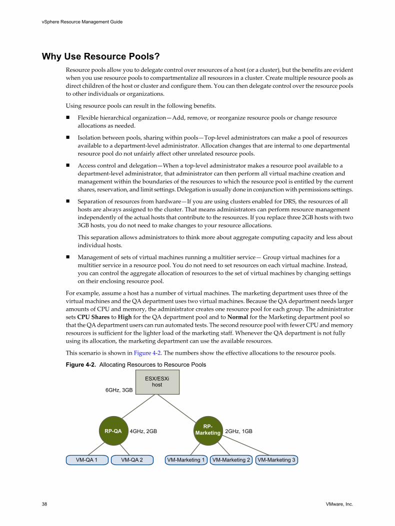
Why Use Resource Pools?Resource pools allow you to delegate control over resources of a host (or a cluster), but the benefits are evidentwhen you use resource pools to compartmentalize all resources in a cluster. Create multiple resource pools asdirect children of the host or cluster and configure them. You can then delegate control over the resource poolsto other individuals or organizations.
Using resource pools can result in the following benefits.
n Flexible hierarchical organization—Add, remove, or reorganize resource pools or change resourceallocations as needed.
n Isolation between pools, sharing within pools—Top-level administrators can make a pool of resourcesavailable to a department-level administrator. Allocation changes that are internal to one departmentalresource pool do not unfairly affect other unrelated resource pools.
n Access control and delegation—When a top-level administrator makes a resource pool available to adepartment-level administrator, that administrator can then perform all virtual machine creation andmanagement within the boundaries of the resources to which the resource pool is entitled by the currentshares, reservation, and limit settings. Delegation is usually done in conjunction with permissions settings.
n Separation of resources from hardware—If you are using clusters enabled for DRS, the resources of allhosts are always assigned to the cluster. That means administrators can perform resource managementindependently of the actual hosts that contribute to the resources. If you replace three 2GB hosts with two3GB hosts, you do not need to make changes to your resource allocations.
This separation allows administrators to think more about aggregate computing capacity and less aboutindividual hosts.
n Management of sets of virtual machines running a multitier service— Group virtual machines for amultitier service in a resource pool. You do not need to set resources on each virtual machine. Instead,you can control the aggregate allocation of resources to the set of virtual machines by changing settingson their enclosing resource pool.
For example, assume a host has a number of virtual machines. The marketing department uses three of thevirtual machines and the QA department uses two virtual machines. Because the QA department needs largeramounts of CPU and memory, the administrator creates one resource pool for each group. The administratorsets CPU Shares to High for the QA department pool and to Normal for the Marketing department pool sothat the QA department users can run automated tests. The second resource pool with fewer CPU and memoryresources is sufficient for the lighter load of the marketing staff. Whenever the QA department is not fullyusing its allocation, the marketing department can use the available resources.
This scenario is shown in Figure 4-2. The numbers show the effective allocations to the resource pools.
Figure 4-2. Allocating Resources to Resource Pools
VM-QA 1 VM-QA 2
6GHz, 3GB
4GHz, 2GB 2GHz, 1GBRP-QA
VM-Marketing 1 VM-Marketing 2 VM-Marketing 3
RP-Marketing
ESX/ESXihost
vSphere Resource Management Guide
38 VMware, Inc.
Create Resource PoolsYou can create a child resource pool of any ESX/ESXi host, resource pool, or DRS cluster.
NOTE If a host has been added to a cluster, you cannot create child resource pools of that host. You can createchild resource pools of the cluster if the cluster is enabled for DRS.
When you create a child resource pool, you are prompted for resource pool attribute information. The systemuses admission control to make sure you cannot allocate resources that are not available.
Procedure
1 Select the intended parent and select File > New > Resource Pool (or click New Resource Pool in theCommands panel of the Summary tab).
2 In the Create Resource Pool dialog box, provide the required information for your resource pool.
3 After you have made all selections, click OK.
vCenter Server creates the resource pool and displays it in the inventory panel. A yellow triangle appearsif any of the selected values are not legal values because of limitations on total available CPU and memory.
After a resource pool has been created, you can add virtual machines to it. A virtual machine’s shares arerelative to other virtual machines (or resource pools) with the same parent resource pool.
Resource Pool AttributesYou can use resource allocation settings to manage a resource pool.
Table 4-1 is a summary of the attributes that you can specify for a resource pool.
Table 4-1. Resource Pool Attributes
Field Description
Name Name of the new resource pool.
Shares Number of CPU or memory shares the resource pool has with respect to the parent’stotal. Sibling resource pools share resources according to their relative share valuesbounded by the reservation and limit. You can select Low, Normal, or High, or selectCustom to specify a number that assigns a share value.
Reservation Guaranteed CPU or memory allocation for this resource pool. A nonzero reservation issubtracted from the unreserved resources of the parent (host or resource pool). Theresources are considered reserved, regardless of whether virtual machines are associatedwith the resource pool. Defaults to 0.
Expandable Reservation Indicates whether expandable reservations are considered during admission control. Ifyou power on a virtual machine in this resource pool, and the reservations of the virtualmachines combined are larger than the reservation of the resource pool, the resourcepool can use resources from its parent or ancestors if this check box is selected (thedefault).
Limit Upper limit for the amount of CPU or memory the host makes available to this resourcepool. Default is Unlimited. To specify a limit, deselect the Unlimitedcheck box.
Chapter 4 Managing Resource Pools
VMware, Inc. 39

Resource Pool Creation ExampleThis procedure example demonstrates how you can create a resource pool with the ESX/ESXi host as the parentresource.
Assume that you have an ESX/ESXi host that provides 6GHz of CPU and 3GB of memory that must be sharedbetween your marketing and QA departments. You also want to share the resources unevenly, giving onedepartment (QA) a higher priority. This can be accomplished by creating a resource pool for each departmentand using the Shares attribute to prioritize the allocation of resources.
The example procedure demonstrates how to create a resource pool, with the ESX/ESXi host as the parentresource.
Procedure
1 In the Create Resource Pool dialog box, type a name for the QA department’s resource pool (for example,RP-QA).
2 Specify Shares of High for the CPU and memory resources of RP-QA.
3 Create a second resource pool, RP-Marketing.
Leave Shares at Normal for CPU and memory.
4 Click OK to exit.
If there is resource contention, RP-QA receives 4GHz and 2GB of memory, and RP-Marketing 2GHz and 1GB.Otherwise, they can receive more than this allotment. Those resources are then available to the virtual machinesin the respective resource pools.
Change Resource Pool AttributesAfter a resource pool is created, you can change its attributes.
Procedure
1 Select the resource pool in the vSphere Client inventory panel.
2 In the Summary tab Command panel, select Edit Settings.
3 In the Edit Settings dialog box, you can change all attributes of the selected resource pool.
Add Virtual Machines to a Resource PoolWhen you create a virtual machine, the New Virtual Machine wizard allows you to specify a resource poollocation as part of the creation process. You can also add an existing virtual machine to a resource pool.
When you move a virtual machine to a new resource pool:
n The virtual machine’s reservation and limit do not change.
n If the virtual machine’s shares are high, medium, or low, %Shares adjusts to reflect the total number ofshares in use in the new resource pool.
n If the virtual machine has custom shares assigned, the share value is maintained.
NOTE Because share allocations are relative to a resource pool, you might have to manually change avirtual machine’s shares when you move it into a resource pool so that the virtual machine’s shares areconsistent with the relative values in the new resource pool. A warning appears if a virtual machine wouldreceive a very large (or very small) percentage of total shares.
vSphere Resource Management Guide
40 VMware, Inc.

n The information displayed in the Resource Allocation tab about the resource pool’s reserved andunreserved CPU and memory resources changes to reflect the reservations associated with the virtualmachine (if any).
NOTE If a virtual machine has been powered off or suspended, it can be moved but overall availableresources (such as reserved and unreserved CPU and memory) for the resource pool are not affected.
Procedure
1 Select the preexisting virtual machine from any location in the inventory.
The virtual machine can be associated with a standalone host, a cluster, or a different resource pool.
2 Drag the virtual machine (or machines) to the resource pool object you want.
If a virtual machine is powered on, and the destination resource pool does not have enough CPU or memoryto guarantee the virtual machine’s reservation, the move fails because admission control does not allow it. Anerror dialog box explains the situation. The error dialog box compares available and requested resources, soyou can consider whether an adjustment might resolve the issue.
Removing Virtual Machines from a Resource PoolYou can remove a virtual machine from a resource pool either by moving the virtual machine to anotherresource pool or deleting it.
Moving a Virtual Machine to a Different Resource PoolYou can drag the virtual machine to another resource pool. You do not need to power off a virtual machine ifyou only move it.
When you remove a virtual machine from a resource pool, the total number of shares associated with theresource pool decreases, so that each remaining share represents more resources. For example, assume youhave a pool that is entitled to 6GHz, containing three virtual machines with shares set to Normal. Assumingthe virtual machines are CPU-bound, each gets an equal allocation of 2GHz. If one of the virtual machines ismoved to a different resource pool, the two remaining virtual machines each receive an equal allocation of3GHz.
Removing a Virtual Machine from the Inventory or Deleting it from the DiskRight-click the virtual machine and click Remove from Inventory or Delete from Disk.
You need to power off the virtual machine before you can completely remove it.
Resource Pool Admission ControlWhen you power on a virtual machine in a resource pool, or try to create a child resource pool, the systemperforms additional admission control to ensure the resource pool’s restrictions are not violated.
Before you power on a virtual machine or create a resource pool, check the CPU Unreserved and memoryUnreserved fields in the resource pool’s Resource Allocation tab to determine whether sufficient resourcesare available.
How Unreserved CPU and memory are computed and whether actions are performed depends on theReservation Type.
Chapter 4 Managing Resource Pools
VMware, Inc. 41
Table 4-2. Reservation Types
Reservation Type Description
Fixed The system checks whether the selected resource pool has sufficient unreservedresources. If it does, the action can be performed. If it does not, a message appears andthe action cannot be performed.
Expandable(default)
The system considers the resources available in the selected resource pool and its directparent resource pool. If the parent resource pool also has the Expandable Reservationoption selected, it can borrow resources from its parent resource pool. Borrowingresources occurs recursively from the ancestors of the current resource pool as long asthe Expandable Reservation option is selected. Leaving this option selected offers moreflexibility, but, at the same time provides less protection. A child resource pool ownermight reserve more resources than you anticipate.
The system does not allow you to violate preconfigured Reservation or Limit settings. Each time youreconfigure a resource pool or power on a virtual machine, the system validates all parameters so all service-level guarantees can still be met.
Expandable Reservations Example 1This example shows you how a resource pool with expandable reservations works.
Assume an administrator manages pool P, and defines two child resource pools, S1 and S2, for two differentusers (or groups).
The administrator knows that users want to power on virtual machines with reservations, but does not knowhow much each user will need to reserve. Making the reservations for S1 and S2 expandable allows theadministrator to more flexibly share and inherit the common reservation for pool P.
Without expandable reservations, the administrator needs to explicitly allocate S1 and S2 a specific amount.Such specific allocations can be inflexible, especially in deep resource pool hierarchies and can complicatesetting reservations in the resource pool hierarchy.
Expandable reservations cause a loss of strict isolation. S1 can start using all of P's reservation, so that nomemory or CPU is directly available to S2.
Expandable Reservations Example 2This example shows how a resource pool with expandable reservations works.
Assume the following scenario (shown in Figure 4-3).
n Parent pool RP-MOM has a reservation of 6GHz and one running virtual machine VM-M1 that reserves1GHz.
n You create a child resource pool RP-KID with a reservation of 2GHz and with Expandable Reservationselected.
n You add two virtual machines, VM-K1 and VM-K2, with reservations of 2GHz each to the child resourcepool and try to power them on.
n VM-K1 can reserve the resources directly from RP-KID (which has 2GHz).
n No local resources are available for VM-K2, so it borrows resources from the parent resource pool, RP-MOM. RP-MOM has 6GHz minus 1GHz (reserved by the virtual machine) minus 2GHz (reserved by RP-KID), which leaves 3GHz unreserved. With 3GHz available, you can power on the 2GHz virtual machine.
vSphere Resource Management Guide
42 VMware, Inc.

Figure 4-3. Admission Control with Expandable Resource Pools: Successful Power-On
VM-K1, 2GHz VM-K2, 2GHz
2GHz
6GHz
RP-KID
VM-M1, 1GHz
RP-MOM
Now, consider another scenario with VM-M1 and VM-M2 (shown in Figure 4-4):
n Power on two virtual machines in RP-MOM with a total reservation of 3GHz.
n You can still power on VM-K1 in RP-KID because 2GHz are available locally.
n When you try to power on VM-K2, RP-KID has no unreserved CPU capacity so it checks its parent. RP-MOM has only 1GHz of unreserved capacity available (5GHz of RP-MOM are already in use—3GHzreserved by the local virtual machines and 2GHz reserved by RP-KID). As a result, you cannot power onVM-K2, which requires a 2GHz reservation.
Figure 4-4. Admission Control with Expandable Resource Pools: Power-On Prevented
VM-K1, 2GHz VM-K2, 2GHz
2GHz
6GHz
RP-KID
VM-M1, 1GHz VM-M2, 2GHz
RP-MOM
Chapter 4 Managing Resource Pools
VMware, Inc. 43

vSphere Resource Management Guide
44 VMware, Inc.
Creating a DRS Cluster 5A DRS cluster is a collection of ESX/ESXi hosts and associated virtual machines with shared resources and ashared management interface. Before you can obtain the benefits of cluster-level resource management youmust create a DRS cluster.
When you add a host to a DRS cluster, the host’s resources become part of the cluster’s resources. In additionto this aggregation of resources, with a DRS cluster you can support cluster-wide resource pools and enforcecluster-level resource allocation policies. The following cluster-level resource management capabilities are alsoavailable.
n Load Balancing — The distribution and usage of CPU and memory resources for all hosts and virtualmachines in the cluster are continuously monitored. DRS compares these metrics to an ideal resourceutilization given the attributes of the cluster’s resource pools and virtual machines, the current demand,and the imbalance target. It then performs (or recommends) virtual machine migrations accordingly. See“Virtual Machine Migration,” on page 47. When you first power on a virtual machine in the cluster, DRSattempts to maintain proper load balancing by either placing the virtual machine on an appropriate hostor making a recommendation. See “Admission Control and Initial Placement,” on page 46.
n Power management— When the VMware Distributed Power Management feature is enabled, DRScompares cluster- and host-level capacity to the demands of the cluster’s virtual machines, including recenthistorical demand. It places (or recommends placing) hosts in standby power mode if sufficient excesscapacity is found or powering on hosts if capacity is needed. Depending on the resulting host power staterecommendations, virtual machines might need to be migrated to and from the hosts as well. See “Managing Power Resources,” on page 62.
n DRS Rules—You can control the placement of virtual machines on hosts within a cluster, by assigningDRS (affinity or anti-affinity) rules. See “Using DRS Rules,” on page 53.
This chapter includes the following topics:
n “Admission Control and Initial Placement,” on page 46
n “Virtual Machine Migration,” on page 47
n “DRS Cluster Prerequisites,” on page 49
n “Create a DRS Cluster,” on page 50
n “Set a Custom Automation Level for a Virtual Machine,” on page 51
n “Disable DRS,” on page 51
VMware, Inc. 45
Admission Control and Initial PlacementWhen you attempt to power on a single virtual machine or a group of virtual machines in a DRS-enabledcluster, vCenter Server performs admission control. It checks that there are enough resources in the cluster tosupport the virtual machines.
If the cluster does not have sufficient resources to power on a single virtual machine, or any of the virtualmachines in a group, a message appears. Otherwise, for each virtual machine, DRS generates arecommendation of a host on which to run the virtual machine and takes one of the following actions.
n Automatically runs the placement recommendation.
n Displays the placement recommendation, which the user can then choose to accept or override.
NOTE No initial placement recommendations are given for virtual machines on standalone hosts or innon-DRS clusters. When powered on, they are placed on the host where they currently reside.
For more information about DRS recommendations, see “DRS Recommendations Page,” on page 69.
Single Virtual Machine Power OnIn a DRS cluster, you can power on a single virtual machine and receive initial placement recommendations.
When you power on a single virtual machine, you have two types of initial placement recommendations:
n A single virtual machine is being powered on and no prerequisite steps are needed.
The user is presented with a list of mutually exclusive initial placement recommendations for the virtualmachine. You can select only one.
n A single virtual machine is being powered on, but prerequisite actions are required.
These actions include powering on a host in standby mode or the migration of other virtual machines fromone host to another. In this case, the recommendations provided have multiple lines, showing each of theprerequisite actions. The user can either accept this entire recommendation or cancel powering on thevirtual machine.
Group Power OnYou can attempt to power on multiple virtual machines at the same time (group power on).
Virtual machines selected for a group power-on attempt do not have to be in the same DRS cluster. They canbe selected across clusters but must be within the same datacenter. It is also possible to include virtual machineslocated in non-DRS clusters or on standalone hosts. These are powered on automatically and not included inany initial placement recommendation.
The initial placement recommendations for group power-on attempts are provided on a per-cluster basis. Ifall of the placement-related actions for a group power-on attempt are in automatic mode, the virtual machinesare powered on with no initial placement recommendation given. If placement-related actions for any of thevirtual machines are in manual mode, the powering on of all of the virtual machines (including those that arein automatic mode) is manual and is included in an initial placement recommendation.
For each DRS cluster that the virtual machines being powered on belong to, there is a single recommendation,which contains all of the prerequisites (or no recommendation). All such cluster-specific recommendations arepresented together under the Power On Recommendations tab.
When a nonautomatic group power-on attempt is made, and virtual machines not subject to an initialplacement recommendation (that is, those on standalone hosts or in non-DRS clusters) are included, vCenterServer attempts to power them on automatically. If these power ons are successful, they are listed under theStarted Power-Ons tab. Any virtual machines that fail to power on are listed under the Failed Power-Ons tab.
vSphere Resource Management Guide
46 VMware, Inc.

Group Power-On ExampleThe user selects three virtual machines in the same datacenter for a group power-on attempt. The first twovirtual machines (VM1 and VM2) are in the same DRS cluster (Cluster1), while the third virtual machine (VM3)is on a standalone host. VM1 is in automatic mode and VM2 is in manual mode. For this scenario, the user ispresented with an initial placement recommendation for Cluster1 (under the Power On Recommendationstab) which consists of actions for powering on VM1 and VM2. An attempt is made to power on VM3automatically and, if successful, it is listed under the Started Power-Ons tab. If this attempt fails, it is listedunder the Failed Power-Ons tab.
Virtual Machine MigrationAlthough DRS performs initial placements so that load is balanced across the cluster, changes in virtualmachine load and resource availability can cause the cluster to become unbalanced. To correct such imbalances,DRS generates migration recommendations.
If DRS is enabled on the cluster, load can be distributed more uniformly to reduce the degree of this imbalance.For example, see Figure 5-1. The three hosts on the left side of this figure are unbalanced. Assume that Host 1,Host 2, and Host 3 have identical capacity, and all virtual machines have the same configuration and load(which includes reservation, if set). However, because Host 1 has six virtual machines, its resources might beoverused while ample resources are available on Host 2 and Host 3. DRS migrates (or recommends themigration of) virtual machines from Host 1 to Host 2 and Host 3. On the right side of the diagram, the properlyload balanced configuration of the hosts that results is displayed.
Figure 5-1. Load Balancing
Host 1
VM1
VM4
VM2 VM3
VM5 VM6
Host 2
VM7
Host 3
VM8 VM9
Host 1
VM1 VM2 VM3
Host 2
VM7 VM4 VM5
Host 3
VM8 VM9 VM6
When a cluster becomes unbalanced, DRS makes recommendations or migrates virtual machines, dependingon the default automation level:
n If the cluster or any of the virtual machines involved are manual or partially automated, vCenter Serverdoes not take automatic actions to balance resources. Instead, the Summary page indicates that migrationrecommendations are available and the DRS Recommendations page displays recommendations forchanges that make the most efficient use of resources across the cluster.
Chapter 5 Creating a DRS Cluster
VMware, Inc. 47

n If the cluster and virtual machines involved are all fully automated, vCenter Server migrates runningvirtual machines between hosts as needed to ensure efficient use of cluster resources.
NOTE Even in an automatic migration setup, users can explicitly migrate individual virtual machines, butvCenter Server might move those virtual machines to other hosts to optimize cluster resources.
By default, automation level is specified for the whole cluster. You can also specify a custom automation levelfor individual virtual machines.
DRS Migration ThresholdThe DRS migration threshold allows you to specify which recommendations are generated and then applied(when the virtual machines involved in the recommendation are in fully automated mode) or shown (if inmanual mode). This threshold is also a measure of how much cluster imbalance across host (CPU and memory)loads is acceptable.
You can move the threshold slider to use one of five settings, ranging from Conservative to Aggressive. Thefive migration settings generate recommendations based on their assigned priority level. Each setting youmove the slider to the right allows the inclusion of one more lower level of priority. The Conservative settinggenerates only priority-one recommendations (mandatory recommendations), the next level to the rightgenerates priority-two recommendations and higher, and so on, down to the Aggressive level which generatespriority-five recommendations and higher (that is, all recommendations.)
A priority level for each migration recommendation is computed using the load imbalance metric of the cluster.This metric is displayed as Current host load standard deviation in the cluster's Summary tab in the vSphereClient. A higher load imbalance leads to higher-priority migration recommendations. For more informationabout this metric and how a recommendation priority level is calculated, see the VMware Knowledge Basearticle "Calculating the priority level of a VMware DRS migration recommendation."
After a recommendation receives a priority level, this level is compared to the migration threshold you set. Ifthe priority level is less than or equal to the threshold setting, the recommendation is either applied (if therelevant virtual machines are in fully automated mode) or displayed to the user for confirmation (if in manualor partially automated mode.)
Migration RecommendationsIf you create a cluster with a default manual or partially automated mode, vCenter Server displays migrationrecommendations on the DRS Recommendations page.
The system supplies as many recommendations as necessary to enforce rules and balance the resources of thecluster. Each recommendation includes the virtual machine to be moved, current (source) host and destinationhost, and a reason for the recommendation. The reason can be one of the following:
n Balance average CPU loads or reservations.
n Balance average memory loads or reservations.
n Satisfy resource pool reservations.
n Satisfy DRS (affinity or anti-affinity) rule.
n Host is entering maintenance mode or standby mode.
NOTE If you are using the VMware Distributed Power Management feature, in addition to migrationrecommendations, DRS provides host power state recommendations.
vSphere Resource Management Guide
48 VMware, Inc.
DRS Cluster PrerequisitesAny host that is added to a DRS cluster must meet certain prerequisites to use cluster features successfully.
Shared StorageEnsure that the managed hosts use shared storage. Shared storage is typically on a storage area network (SAN)but can also be implemented using NAS shared storage.
See the iSCSI SAN Configuration Guide and the Fibre Channel SAN Configuration Guide for additional informationon SAN and the ESX Configuration Guide or ESXi Configuration Guide for information on other shared storage.
Shared VMFS VolumeConfigure all managed hosts to use shared VMFS volumes.
n Place the disks of all virtual machines on VMFS volumes that are accessible by source and destinationhosts.
n Set access mode for the shared VMFS to public.
n Ensure the VMFS volume is sufficiently large to store all virtual disks for your virtual machines.
n Ensure all VMFS volumes on source and destination hosts use volume names, and all virtual machinesuse those volume names for specifying the virtual disks.
NOTE Virtual machine swap files also need to be on a VMFS accessible to source and destination hosts (justlike .vmdk virtual disk files). This requirement no longer applies if all source and destination hosts are ESXServer 3.5 or higher and using host-local swap. In that case, VMotion with swap files on unshared storage issupported. Swap files are placed on a VMFS by default, but administrators might override the file locationusing advanced virtual machine configuration options.
Processor CompatibilityTo avoid limiting the capabilities of DRS, you should maximize the processor compatibility of source anddestination hosts in the cluster.
VMotion transfers the running architectural state of a virtual machine between underlying ESX/ESXi hosts.VMotion compatibility means that the processors of the destination host must be able to resume executionusing the equivalent instructions where the processors of the source host were suspended. Processor clockspeeds and cache sizes might vary, but processors must come from the same vendor class (Intel versus AMD)and same processor family to be compatible for migration with VMotion.
Processor families such as Xeon MP and Opteron are defined by the processor vendors. You can distinguishdifferent processor versions within the same family by comparing the processors’ model, stepping level, andextended features.
In some cases, processor vendors have introduced significant architectural changes within the same processorfamily (such as 64-bit extensions and SSE3). VMware identifies these exceptions if it cannot guaranteesuccessful migration with VMotion.
vCenter Server provides features that help ensure that virtual machines migrated with VMotion meet processorcompatibility requirements. These features include:
n Enhanced VMotion Compatibility (EVC) – You can use EVC to help ensure VMotion compatibility for thehosts in a cluster. EVC ensures that all hosts in a cluster present the same CPU feature set to virtualmachines, even if the actual CPUs on the hosts differ. This prevents migrations with VMotion from failingdue to incompatible CPUs.
Chapter 5 Creating a DRS Cluster
VMware, Inc. 49

Configure EVC from the Cluster Settings dialog box. The hosts in a cluster must meet certain requirementsfor the cluster to use EVC. For more information on EVC and EVC requirements, see Basic SystemAdministration.
n CPU compatibility masks – vCenter Server compares the CPU features available to a virtual machine withthe CPU features of the destination host to determine whether to allow or disallow migrations withVMotion. By applying CPU compatibility masks to individual virtual machines, you can hide certain CPUfeatures from the virtual machine and potentially prevent migrations with VMotion from failing due toincompatible CPUs.
VMotion RequirementsTo enable the use of DRS migration recommendations, the hosts in your cluster must be part of a VMotionnetwork. If the hosts are not in the VMotion network, DRS can still make initial placement recommendations.
To be configured for VMotion, each host in the cluster must meet the following requirements:
n The virtual machine configuration file for ESX/ESXi hosts must reside on a VMware Virtual Machine FileSystem (VMFS).
n VMotion does not support raw disks or migration of applications clustered using Microsoft Cluster Service(MSCS).
n VMotion requires a private Gigabit Ethernet migration network between all of the VMotion enabledmanaged hosts. When VMotion is enabled on a managed host, configure a unique network identity objectfor the managed host and connect it to the private migration network.
Create a DRS ClusterCreate a DRS cluster using the New Cluster wizard in the vSphere Client.
Prerequisites
You can create a cluster without a special license, but you must have a license to enable a cluster for DRS (orVMware HA).
Procedure
1 Right-click a datacenter or folder in the vSphere Client and select New Cluster.
2 Name the Cluster in the Name field.
This name appears in the vSphere Client inventory panel.
3 Enable the DRS feature by clicking the VMware DRS box.
You can also enable the VMware HA feature by clicking VMware HA.
4 Click Next.
5 Select a default automation level for DRS.
6 Set the migration threshold for DRS.
7 Click Next.
8 Specify the default power management setting for the cluster.
If you enable power management, select a DPM threshold setting.
9 Click Next.
10 If appropriate, enable Enhanced VMotion Compatibility (EVC) and select the mode it should operate in.
11 Click Next.
vSphere Resource Management Guide
50 VMware, Inc.
12 Select a location for the swapfiles of your virtual machines.
You can either store a swapfile in the same directory as the virtual machine itself, or a datastore specifiedby the host (host-local swap)
13 Click Next.
14 Review the summary page that lists the options you selected.
15 Click Finish to complete cluster creation, or click Back to go back and make modifications to the clustersetup.
A new cluster does not include any hosts or virtual machines.
To add hosts and virtual machines to the cluster see “Adding Hosts to a Cluster,” on page 55 and “RemovingVirtual Machines from a Cluster,” on page 57.
Set a Custom Automation Level for a Virtual MachineAfter you create a DRS cluster, you can customize the automation level for individual virtual machines tooverride the cluster’s default automation level.
Procedure
1 Select the cluster in the vSphere Client inventory.
2 Right-click and select Edit Settings.
3 In the Cluster Settings dialog box, under VMware DRS select Virtual Machine Options.
4 Select the Enable individual virtual machine automation levels check box.
5 Select an individual virtual machine, or select multiple virtual machines.
6 Right-click and select an automation mode.
7 Click OK.
NOTE Other VMware products or features, such as VMware vApp and VMware Fault Tolerance, mightoverride the automation levels of virtual machines in a DRS cluster. Refer to the product-specificdocumentation for details.
Disable DRSYou can turn off DRS for a cluster.
When DRS is disabled, the cluster’s resource pool hierarchy and DRS rules (see “Using DRS Rules,” onpage 53) are not reestablished when DRS is turned back on. So if you disable DRS, the resource pools areremoved from the cluster. To avoid losing the resource pools, instead of disabling DRS, you should suspendit by changing the DRS automation level to manual (and disabling any virtual machine overrides). Thisprevents automatic DRS actions, but preserves the resource pool hierarchy.
Procedure
1 Select the cluster in the vSphere Client inventory.
2 Right click and select Edit Settings.
3 In the left panel, select General, and deselect the Turn On VMware DRScheck box.
4 Click OK to turn off DRS.
Chapter 5 Creating a DRS Cluster
VMware, Inc. 51

vSphere Resource Management Guide
52 VMware, Inc.
Using DRS Clusters to ManageResources 6
After you create a DRS cluster, you can customize it and use it to manage resources.
To customize your DRS cluster and the resources it contains you can configure DRS rules and you can add andremove hosts and virtual machines. When a cluster’s settings and resources have been defined, you shouldensure that it is and remains a valid cluster. You can also use a valid DRS cluster to manage power resourcesand interoperate with VMware HA.
This chapter includes the following topics:
n “Using DRS Rules,” on page 53
n “Adding Hosts to a Cluster,” on page 55
n “Adding Virtual Machines to a Cluster,” on page 56
n “Remove Hosts from a Cluster,” on page 56
n “Removing Virtual Machines from a Cluster,” on page 57
n “DRS Cluster Validity,” on page 58
n “Managing Power Resources,” on page 62
Using DRS RulesYou can control the placement of virtual machines on hosts within a cluster, by using DRS affinity and anti-affinity rules. An affinity rule specifies that two or more virtual machines be placed on the same host. An anti-affinity rule is limited to two virtual machines, and it requires that these two virtual machines not be placedon the same host.
If two rules conflict, the older one will take precedence, and the newer rule is disabled. DRS only tries to satisfyenabled rules, even if they are in violation. Disabled rules are ignored. DRS gives higher precedence topreventing violations of anti-affinity rules than violations of affinity rules.
To check if any enabled DRS rules are being violated, select the cluster in the inventory panel of the vSphereClient, select the DRS tab, and click Faults. Any rule currently being violated has a corresponding fault on thispage. Read the fault to determine why DRS is not able to satisfy the particular rule.
NOTE DRS rules are different from an individual host’s CPU affinity rules.
Create DRS RulesYou can create DRS rules to specify virtual machine affinity or anti-affinity.
Procedure
1 Select the cluster in the vSphere Client inventory.
VMware, Inc. 53

2 Right-Click and select Edit Settings.
3 In the left panel under VMware DRS select Rules.
4 Click Add.
5 In the Virtual Machine Rule dialog box, name the rule.
6 Select one of the options from the pop-up menu:
n Keep Virtual Machines Together
One virtual machine cannot be part of more than one such rule.
n Separate Virtual Machines
This type of rule cannot contain more than two virtual machines.
7 Click Add and click OK.
The rule is created.
Edit DRS RulesYou can edit DRS rules.
Procedure
1 Display the cluster in the inventory.
2 Right-click the cluster and select Edit Settings.
The cluster's Settings dialog box appears.
3 In the left pane under VMware DRS, select Rules.
4 Select a rule in the right pane and click Edit.
5 Make changes in the dialog box and click OK.
Disable DRS RulesYou can disable DRS rules.
Procedure
1 Select the cluster in the vSphere Client inventory.
2 Select Edit Settingsfrom the right-click menu.
3 In the left panel, select Rules under VMware DRS.
4 Deselect the check box to the left of the rule and click OK.
What to do next
You can later enable the rule by reselecting the check box.
Delete DRS RulesYou can delete DRS rules.
Procedure
1 Select the cluster in the vSphere Client inventory.
2 Select Edit Settingsfrom the right-click menu.
3 In the left panel, select Rules under VMware DRS.
vSphere Resource Management Guide
54 VMware, Inc.

4 Select the rule you want to remove and click Remove.
The rule is deleted.
Adding Hosts to a ClusterThe procedure for adding hosts to a cluster is different for hosts managed by the same vCenter Server (managedhosts) than for hosts not managed by that server.
After a host has been added, the virtual machines deployed to the host become part of the cluster and DRS canrecommend migration of some virtual machines to other hosts in the cluster.
Add a Managed Host to a ClusterWhen you add a standalone host already being managed by vCenter Server to a DRS cluster, the host’sresources become associated with the cluster.
You can decide whether you want to associate existing virtual machines and resource pools with the cluster’sroot resource pool or graft the resource pool hierarchy.
NOTE If a host has no child resource pools or virtual machines, the host’s resources are added to the clusterbut no resource pool hierarchy with a top-level resource pool is created.
Procedure
1 Select the host from either the inventory or list view.
2 Drag the host to the target cluster object.
3 Select what to do with the host’s virtual machines and resource pools.
n Put this host’s virtual machines in the cluster’s root resource pool
vCenter Server removes all existing resource pools of the host and the virtual machines in the host’shierarchy are all attached to the root. Because share allocations are relative to a resource pool, youmight have to manually change a virtual machine’s shares after selecting this option, which destroysthe resource pool hierarchy.
n Create a resource pool for this host’s virtual machines and resource pools
vCenter Server creates a top-level resource pool that becomes a direct child of the cluster and addsall children of the host to that new resource pool. You can supply a name for that new top-levelresource pool. The default is Grafted from <host_name>.
The host is added to the cluster.
Add an Unmanaged Host to a ClusterYou can add an unmanaged host to a cluster. Such a host is not currently managed by the same vCenter Serversystem as the cluster and it is not visible in the vSphere Client.
Procedure
1 Select the cluster to which to add the host and select Add Host from the right-click menu.
2 Enter the host name, user name, and password, and click Next.
3 View the summary information and click Next.
4 Select what to do with the host’s virtual machines and resource pools.
n Put this host’s virtual machines in the cluster’s root resource pool
Chapter 6 Using DRS Clusters to Manage Resources
VMware, Inc. 55
vCenter Server removes all existing resource pools of the host and the virtual machines in the host’shierarchy are all attached to the root. Because share allocations are relative to a resource pool, youmight have to manually change a virtual machine’s shares after selecting this option, which destroysthe resource pool hierarchy.
n Create a resource pool for this host’s virtual machines and resource pools
vCenter Server creates a top-level resource pool that becomes a direct child of the cluster and addsall children of the host to that new resource pool. You can supply a name for that new top-levelresource pool. The default is Grafted from <host_name>.
The host is added to the cluster.
Adding Virtual Machines to a ClusterYou can add a virtual machine to a cluster in three ways.
n When you add a host to a cluster, all virtual machines on that host are added to the cluster.
n When a virtual machine is created, the New Virtual Machine wizard prompts you for the location to placethe virtual machine. You can select a standalone host or a cluster and you can select any resource poolinside the host or cluster.
n You can migrate a virtual machine from a standalone host to a cluster or from a cluster to another clusterusing the Migrate Virtual Machine wizard. To start this wizard either drag the virtual machine object ontop of the cluster object or right-click the virtual machine name and select Migrate.
NOTE You can drag a virtual machine directly to a resource pool within a cluster. In this case, the MigrateVirtual Machine wizard is started but the resource pool selection page does not appear. Migrating directlyto a host within a cluster is not allowed because the resource pool controls the resources.
Remove Hosts from a ClusterYou can remove hosts from a cluster.
Prerequisites
Before you remove a host from a DRS cluster, consider the issues involved.
n Resource Pool Hierarchies – When you remove a host from a cluster, the host retains only the root resourcepool, even if you used a DRS cluster and decided to graft the host resource pool when you added the hostto the cluster. In that case, the hierarchy remains with the cluster. You can create a host-specific resourcepool hierarchy.
NOTE Ensure that you remove the host from the cluster by first placing it in maintenance mode. If youinstead disconnect the host before removing it from the cluster, the host retains the resource pool thatreflects the cluster hierarchy.
n Virtual Machines – A host must be in maintenance mode before you can remove it from the cluster andfor a host to enter maintenance mode all powered-on virtual machines must be migrated off that host.When you request that a host enter maintenance mode, you are also asked whether you want to migrateall the powered-off virtual machines on that host to other hosts in the cluster.
n Invalid Clusters – When you remove a host from a cluster, the resources available for the cluster decrease.If the cluster has enough resources to satisfy the reservations of all virtual machines and resource poolsin the cluster, the cluster adjusts resource allocation to reflect the reduced amount of resources. If thecluster does not have enough resources to satisfy the reservations of all resource pools, but there areenough resources to satisfy the reservations for all virtual machines, an alarm is issued and the cluster ismarked yellow. DRS continues to run.
vSphere Resource Management Guide
56 VMware, Inc.

Procedure
1 Select the host and select Enter Maintenance Mode from the right-click menu.
2 After the host is in maintenance mode, drag it to a different inventory location, either the top-leveldatacenter or a different cluster.
When you move the host, its resources are removed from the cluster. If you grafted the host’s resourcepool hierarchy onto the cluster, that hierarchy remains with the cluster.
After you move the host, you can:
n Remove the host from vCenter Server. (Select Remove from the right-click menu.)
n Run the host as a standalone host under vCenter Server. (Select Exit Maintenance Mode from the right-click menu.)
n Move the host into another cluster.
Using Maintenance ModeYou place a host in maintenance mode when you need to service it, for example, to install more memory. Ahost enters or leaves maintenance mode only as the result of a user request.
Virtual machines that are running on a host entering maintenance mode need to be migrated to another host(either manually or automatically by DRS) or shut down. The host is in a state of Entering MaintenanceMode until all running virtual machines are powered down or migrated to different hosts. You cannot poweron virtual machines or migrate virtual machines to a host entering maintenance mode.
When no more running virtual machines are on the host, the host’s icon changes to include undermaintenance and the host’s Summary panel indicates the new state. While in maintenance mode, the host doesnot allow you to deploy or power on a virtual machine.
NOTE DRS does not recommend (or perform, in fully automated mode) any virtual machine migrations offof a host entering maintenance or standby mode if the VMware HA failover level would be violated after thehost enters the requested mode.
Using Standby ModeWhen a host machine is placed in standby mode, it is powered off.
Normally, hosts are placed in standby mode by the VMware DPM feature to optimize power usage. You canalso place a host in standby mode manually. However, DRS might undo (or recommend undoing) your changethe next time it runs. To force a host to remain off, place it in maintenance mode and power it off.
Removing Virtual Machines from a ClusterYou can remove virtual machines from a cluster.
You can remove a virtual machine from a cluster in two ways:
n When you remove a host from a cluster, all of the powered-off virtual machines that you do not migrateto other hosts are removed as well. You can remove a host only if it is in maintenance mode or disconnected.If you remove a host from a DRS cluster, the cluster can become yellow because it is overcommitted.
n You can migrate a virtual machine from a cluster to a standalone host or from a cluster to another clusterusing the Migrate Virtual Machine wizard. To start this wizard either drag the virtual machine object ontop of the cluster object or right-click the virtual machine name and select Migrate.
If the virtual machine is a member of a DRS cluster rules group, vCenter Server displays a warning beforeit allows the migration to proceed. The warning indicates that dependent virtual machines are notmigrated automatically. You have to acknowledge the warning before migration can proceed.
Chapter 6 Using DRS Clusters to Manage Resources
VMware, Inc. 57
DRS Cluster ValidityThe vSphere Client indicates whether a DRS cluster is valid, overcommitted (yellow), or invalid (red).
DRS clusters become overcommitted or invalid for several reasons.
n A cluster might become overcommitted if a host fails.
n A cluster becomes invalid if vCenter Server is unavailable and you power on virtual machines using avSphere Client connected directly to an ESX/ESXi host.
n A cluster becomes invalid if the user reduces the reservation on a parent resource pool while a virtualmachine is in the process of failing over.
n If changes are made to hosts or virtual machines using a vSphere Client connected to an ESX/ESXi hostwhile vCenter Server is unavailable, those changes take effect. When vCenter Server becomes availableagain, you might find that clusters have turned red or yellow because cluster requirements are no longermet.
When considering cluster validity scenarios, you should understand these terms.
Reservation A fixed, guaranteed allocation for the resource pool input by the user.
Reservation Used The sum of the reservation or reservation used (whichever is larger) for eachchild resource pool, added recursively.
Unreserved This nonnegative number differs according to resource pool type.
Table 6-1. Resource Pool Unreserved Numbers
Resource Pool Type Number Used
Nonexpandable resource pools Reservation minus reservation used.
Expandable resource pools (Reservation minus reservation used) plus any unreservedresources that can be borrowed from its ancestor resourcepools.
Valid DRS ClustersA valid cluster has enough resources to meet all reservations and to support all running virtual machines.
Figure 6-1 shows an example of a valid cluster with fixed resource pools and how its CPU and memoryresources are computed.
vSphere Resource Management Guide
58 VMware, Inc.
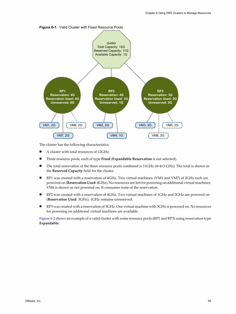
Figure 6-1. Valid Cluster with Fixed Resource Pools
clusterTotal Capacity: 12G
Reserved Capacity: 11GAvailable Capacity: 1G
RP1Reservation: 4G
Reservation Used: 4GUnreserved: 0G
RP2Reservation: 4G
Reservation Used: 3GUnreserved: 1G
RP3Reservation: 3G
Reservation Used: 3GUnreserved: 0G
VM1, 2G
VM7, 2G
VM2, 2G
VM4, 1G VM8, 2G
VM3, 3G VM5, 2GVM6, 2G
The cluster has the following characteristics:
n A cluster with total resources of 12GHz.
n Three resource pools, each of type Fixed (Expandable Reservation is not selected).
n The total reservation of the three resource pools combined is 11GHz (4+4+3 GHz). The total is shown inthe Reserved Capacity field for the cluster.
n RP1 was created with a reservation of 4GHz. Two virtual machines. (VM1 and VM7) of 2GHz each arepowered on (Reservation Used: 4GHz). No resources are left for powering on additional virtual machines.VM6 is shown as not powered on. It consumes none of the reservation.
n RP2 was created with a reservation of 4GHz. Two virtual machines of 1GHz and 2GHz are powered on(Reservation Used: 3GHz). 1GHz remains unreserved.
n RP3 was created with a reservation of 3GHz. One virtual machine with 3GHz is powered on. No resourcesfor powering on additional virtual machines are available.
Figure 6-2 shows an example of a valid cluster with some resource pools (RP1 and RP3) using reservation typeExpandable.
Chapter 6 Using DRS Clusters to Manage Resources
VMware, Inc. 59

Figure 6-2. Valid Cluster with Expandable Resource Pools
clusterTotal Capacity: 16G
Reserved Capacity: 16GAvailable Capacity: 0G
RP1 (expandable)Reservation: 4G
Reservation Used: 6GUnreserved: 0G
RP2Reservation: 5G
Reservation Used: 3GUnreserved: 2G
RP3 (expandable)Reservation: 5G
Reservation Used: 5GUnreserved: 0G
VM1, 2G
VM7, 2G
VM2, 2G
VM4, 1G VM8, 2G
VM3, 3G VM5, 2GVM6, 2G
A valid cluster can be configured as follows:
n A cluster with total resources of 16GHz.
n RP1 and RP3 are of type Expandable, RP2 is of type Fixed.
n The total reservation used of the three resource pools combined is 16GHz (6GHz for RP1, 5GHz for RP2,and 5GHz for RP3). 16GHz shows up as the Reserved Capacity for the cluster at top level.
n RP1 was created with a reservation of 4GHz. Three virtual machines of 2GHz each are powered on. Twoof those virtual machines (for example, VM1 and VM7) can use RP1’s reservations, the third virtualmachine (VM6) can use reservations from the cluster’s resource pool. (If the type of this resource poolwere Fixed, you could not power on the additional virtual machine.)
n RP2 was created with a reservation of 5GHz. Two virtual machines of 1GHz and 2GHz are powered on(Reservation Used: 3GHz). 2GHz remains unreserved.
RP3 was created with a reservation of 5GHz. Two virtual machines of 3GHz and 2GHz are powered on.Even though this resource pool is of type Expandable, no additional 2GHz virtual machine can be poweredon because the parent’s extra resources are already used by RP1.
Overcommitted DRS ClustersA cluster becomes overcommitted (yellow) when the tree of resource pools and virtual machines is internallyconsistent but the cluster does not have the capacity to support all resources reserved by the child resourcepools.
There will always be enough resources to support all running virtual machines because, when a host becomesunavailable, all its virtual machines become unavailable. A cluster typically turns yellow when cluster capacityis suddenly reduced, for example, when a host in the cluster becomes unavailable. VMware recommends thatyou leave adequate additional cluster resources to avoid your cluster turning yellow.
Consider the following example, as shown in Figure 6-3.
vSphere Resource Management Guide
60 VMware, Inc.

Figure 6-3. Yellow Cluster
Xcluster
Total Capacity: 12G 8GReserved Capacity: 12GAvailable Capacity: 0G
RP1 (expandable)Reservation: 4G
Reservation Used: 4GUnreserved: 0G
RP2Reservation: 5G
Reservation Used: 3GUnreserved: 2G
RP3 (expandable)Reservation: 3G
Reservation Used: 3GUnreserved: 0G
VM1, 2G
VM7, 0G
VM2, 2G
VM4, 1G
VM3, 3G VM5, 5GVM6, 2G
In this example:
n A cluster with total resources of 12GHz coming from three hosts of 4GHz each.
n Three resource pools reserving a total of 12GHz.
n The total reservation used by the three resource pools combined is 12GHz (4+5+3 GHz). That shows upas the Reserved Capacity in the cluster.
n One of the 4GHz hosts becomes unavailable, so total resources reduce to 8GHz.
n At the same time, VM4 (1GHz) and VM3 (3GHz), which were running on the host that failed, are no longerrunning.
n The cluster is now running virtual machines that require a total of 6GHz. The cluster still has 8GHzavailable, which is sufficient to meet virtual machine requirements.
The resource pool reservations of 12GHz can no longer be met, so the cluster is marked as yellow.
Invalid DRS ClustersA cluster enabled for DRS becomes invalid (red) when the tree is no longer internally consistent, that is, resourceconstraints are not observed.
The total amount of resources in the cluster does not affect whether the cluster is red. A cluster can be red,even if enough resources exist at the root level, if there is an inconsistency at a child level.
You can resolve a red DRS cluster problem either by powering off one or more virtual machines, moving virtualmachines to parts of the tree that have sufficient resources, or editing the resource pool settings in the red part.Adding resources typically helps only when you are in the yellow state.
Chapter 6 Using DRS Clusters to Manage Resources
VMware, Inc. 61
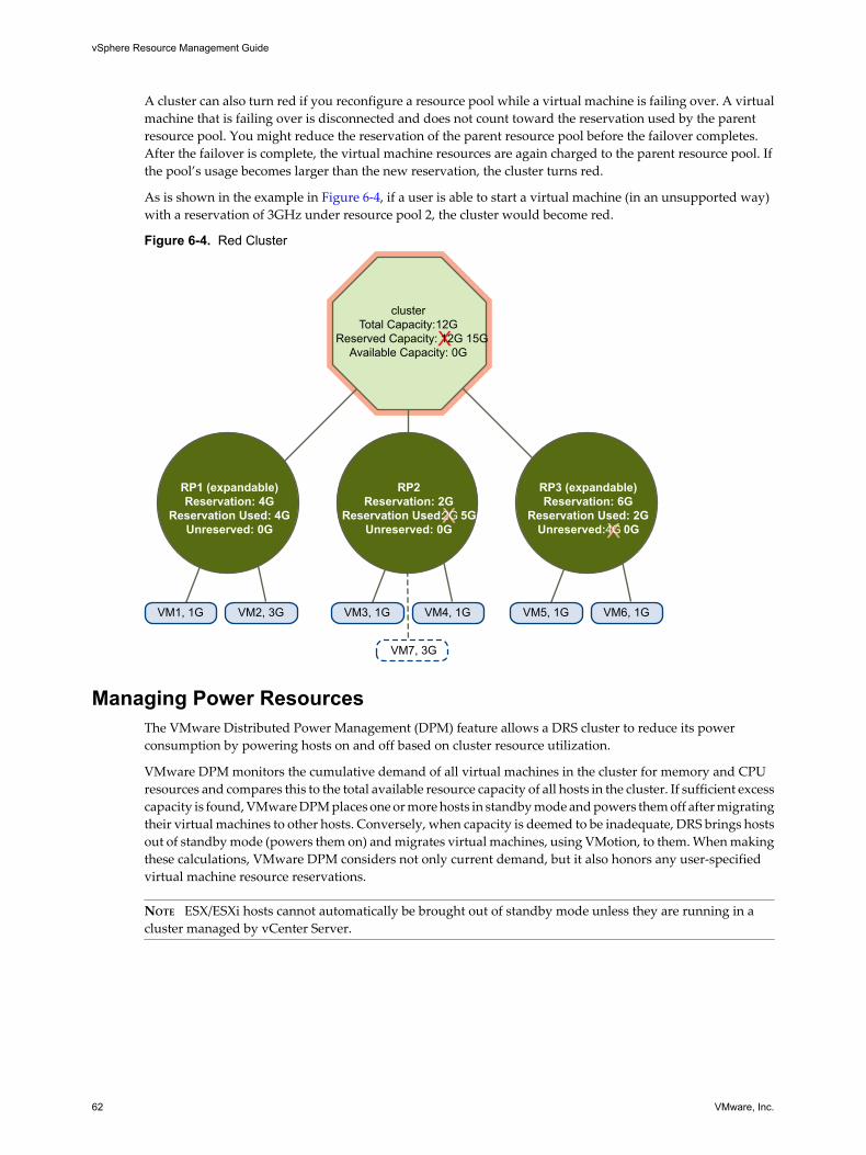
A cluster can also turn red if you reconfigure a resource pool while a virtual machine is failing over. A virtualmachine that is failing over is disconnected and does not count toward the reservation used by the parentresource pool. You might reduce the reservation of the parent resource pool before the failover completes.After the failover is complete, the virtual machine resources are again charged to the parent resource pool. Ifthe pool’s usage becomes larger than the new reservation, the cluster turns red.
As is shown in the example in Figure 6-4, if a user is able to start a virtual machine (in an unsupported way)with a reservation of 3GHz under resource pool 2, the cluster would become red.
Figure 6-4. Red Cluster
clusterTotal Capacity: 12G
Reserved Capacity: 12G 15GAvailable Capacity: 0G
RP1 (expandable)Reservation: 4G
Reservation Used: 4GUnreserved: 0G
RP2Reservation: 2G
Reservation Used: 2G 5GUnreserved: 0G
RP3 (expandable)Reservation: 6G
Reservation Used: 2GUnreserved: 4G 0G
VM1, 1G
VM7, 3G
VM2, 3G VM3, 1G VM4, 1G VM5, 1G VM6, 1G
Managing Power ResourcesThe VMware Distributed Power Management (DPM) feature allows a DRS cluster to reduce its powerconsumption by powering hosts on and off based on cluster resource utilization.
VMware DPM monitors the cumulative demand of all virtual machines in the cluster for memory and CPUresources and compares this to the total available resource capacity of all hosts in the cluster. If sufficient excesscapacity is found, VMware DPM places one or more hosts in standby mode and powers them off after migratingtheir virtual machines to other hosts. Conversely, when capacity is deemed to be inadequate, DRS brings hostsout of standby mode (powers them on) and migrates virtual machines, using VMotion, to them. When makingthese calculations, VMware DPM considers not only current demand, but it also honors any user-specifiedvirtual machine resource reservations.
NOTE ESX/ESXi hosts cannot automatically be brought out of standby mode unless they are running in acluster managed by vCenter Server.
vSphere Resource Management Guide
62 VMware, Inc.

VMware DPM can use one of three power management protocols to bring a host out of standby mode:Intelligent Platform Management Interface (IPMI), Hewlett-Packard Integrated Lights-Out (iLO), or Wake-On-LAN (WOL). Each protocol requires its own hardware support and configuration. If a host does not supportany of these protocols it cannot be put into standby mode by VMware DPM. If a host supports multipleprotocols, they are used in the following order: IPMI, iLO, WOL.
NOTE Do not disconnect a host in standby mode or move it out of the DRS cluster without first powering iton, otherwise vCenter Server is not able to power the host back on.
Configure IPMI or iLO Settings for VMware DPMIPMI is a hardware-level specification and Hewlett-Packard iLO is an embedded server managementtechnology. Each of them describes and provides an interface for remotely monitoring and controllingcomputers.
You must perform the following procedure on each host.
Prerequisites
Both IPMI and iLO require a hardware Baseboard Management Controller (BMC) to provide a gateway foraccessing hardware control functions, and allow the interface to be accessed from a remote system using serialor LAN connections. The BMC is powered-on even when the host itself is powered-off. If properly enabled,the BMC can respond to remote power-on commands.
If you plan to use IPMI or iLO as a wake protocol, you must configure the BMC. BMC configuration steps varyaccording to model. See your vendor’s documentation for more information. With IPMI, you must also ensurethat the BMC LAN channel is configured to be always available and to allow operator-privileged commands.On some IPMI systems, when you enable "IPMI over LAN" you must configure this in the BIOS and specify aparticular IPMI account.
VMware DPM using only IPMI supports MD5- and plaintext-based authentication, but MD2-basedauthentication is not supported. vCenter Server uses MD5 if a host's BMC reports that it is supported andenabled for the Operator role. Otherwise, plaintext-based authentication is used if the BMC reports it issupported and enabled. If neither MD5 nor plaintext authentication is enabled, IPMI cannot be used with thehost and vCenter Server attempts to use Wake-on-LAN.
Procedure
1 Select the host in the vSphere Client inventory.
2 Click the Configuration tab.
3 Click Power Management.
4 Click Properties.
5 Enter the following information.
n User name and password for a BMC account. (The user name must have the ability to remotely powerthe host on.)
n IP address of the NIC associated with the BMC, as distinct from the IP address of the host. The IPaddress should be static or a DHCP address with infinite lease.
n MAC address of the NIC associated with the BMC.
6 Click OK.
Chapter 6 Using DRS Clusters to Manage Resources
VMware, Inc. 63
Test Wake-on-LAN for VMware DPMThe use of Wake-on-LAN (WOL) for the VMware DPM feature is fully supported, if you configure andsuccessfully test it according to the VMware guidelines. You must perform these steps before enabling VMwareDPM for a cluster for the first time or on any host that is being added to a cluster that is using VMware DPM.
Prerequisites
Before testing WOL, ensure that your cluster meets the prerequisites.
n Your cluster must contain at least two ESX 3.5 (or ESX 3i version 3.5) or later hosts.
n Each host's VMotion networking link must be working correctly. The VMotion network should also be asingle IP subnet, not multiple subnets separated by routers.
n The VMotion NIC on each host must support WOL. To check for WOL support, first determine the nameof the physical network adapter corresponding to the VMkernel port by selecting the host in the inventorypanel of the vSphere Client, selecting the Configuration tab, and clicking Networking. After you havethis information, click on Network Adapters and find the entry corresponding to the network adapter.The Wake On LAN Supported column for the relevant adapter should show Yes.
n To display the WOL-compatibility status for each NIC on a host, select the host in the inventory panel ofthe vSphere Client, select the Configuration tab, and click Network Adapters. The NIC must show Yesin the Wake On LAN Supported column.
n The switch port that each WOL-supporting VMotion NIC is plugged into should be set to auto negotiatethe link speed, and not set to a fixed speed (for example, 1000 Mb/s). Many NICs support WOL only ifthey can switch to 100 Mb/s or less when the host is powered off.
After you verify these prerequisites, test each ESX/ESXi host that is going to use WOL to support VMwareDPM. When you test these hosts, ensure that the VMware DPM feature is disabled for the cluster.
CAUTION Ensure that any host being added to a VMware DPM cluster that uses WOL as a wake protocol istested and disabled from using power management if it fails the testing. If this is not done, VMware DPMmight power off hosts that it subsequently cannot power back up.
Procedure
1 Click the Enter Standby Mode command on the host's Summary tab in the vSphere Client.
This action powers down the host.
2 Try to bring the host out of standby mode by clicking the Power Oncommand on the host's Summary tab.
3 Observe whether or not the host successfully powers back on.
4 For any host that fails to exit standby mode successfully, select the host in the cluster Settings dialog box’sHost Options page and change its Power Management setting to Disabled.
After you do this, VMware DPM does not consider that host a candidate for being powered-off.
Enabling VMware DPM for a DRS ClusterAfter you have performed any configuration or testing steps required by the wake protocol you are using oneach host, you can enable VMware DPM.
To do this, configure the power management automation level, threshold, and host-level overrides. Thesesettings are configured under Power Management in the cluster’s Settings dialog box.
vSphere Resource Management Guide
64 VMware, Inc.

Automation LevelWhether the host power state and migration recommendations generated by VMware DPM are executedautomatically or not depends upon the power management automation level selected for the feature.
The automation level is configured under Power Management in the cluster’s Settings dialog box. The optionsavailable are:
n Off – The feature is disabled and no recommendations will be made.
n Manual – Host power operation and related virtual machine migration recommendations are made, butnot automatically executed. These recommendations appear on the cluster’s DRS tab in the vSphere Client.
n Automatic – Host power operations are automatically executed if related virtual machine migrations canall be executed automatically.
NOTE The power management automation level is not the same as the DRS automation level.
VMware DPM ThresholdThe power state (host power on or off) recommendations generated by the VMware DPM feature are assignedpriorities that range from priority-one recommendations to priority-five recommendations.
These priority ratings are based on the amount of over- or under-utilization found in the DRS cluster and theimprovement that is expected from the intended host power state change. A priority-one recommendation ismandatory, while a priority-five recommendation brings only slight improvement.
The threshold is configured under Power Management in the cluster’s Settings dialog box. Each level youmove the VMware DPM Threshold slider to the right allows the inclusion of one more lower level of priorityin the set of recommendations that are executed automatically or appear as recommendations to be manuallyexecuted. At the Conservative setting, VMware DPM only generates priority-one recommendations, the nextlevel to the right only priority-two and higher, and so on, down to the Aggressive level which generatespriority-five recommendations and higher (that is, all recommendations.)
NOTE The DRS threshold and the VMware DPM threshold are essentially independent. You can differentiatethe aggressiveness of the migration and host-power-state recommendations they respectively provide.
Host-Level OverridesWhen you enable VMware DPM in a DRS cluster, by default all hosts in the cluster inherit its VMware DPMautomation level.
You can override this default for an individual host by selecting the host Host Options page of the cluster'sSettings dialog box and clicking its Power Management setting. You can change this setting to the followingoptions:
n Disabled
n Manual
n Automatic
NOTE Do not change a host's Power Management setting if it has been set to Disabled due to failed exit standbymode testing.
Chapter 6 Using DRS Clusters to Manage Resources
VMware, Inc. 65

After enabling and running VMware DPM, you can verify that it is functioning properly by viewing each host’sLast Time Exited Standby information displayed on the Host Options page in the cluster Settings dialog boxand on the Hosts tab for each cluster. This field shows a timestamp and whether vCenter Server Succeededor Failed the last time it attempted to bring the host out of standby mode. If no such attempt has been made,the field displays Never.
NOTE Times for the Last Time Exited Standbyfield are derived from the vCenter Server event log. If this logis cleared, the times are reset to Never.
Monitoring VMware DPMYou can use event-based alarms in vCenter Server to monitor VMware DPM.
The most serious potential error you face when using VMware DPM is the failure of a host to exit standbymode when its capacity is needed by the DRS cluster. You can monitor for instances when this error occurs byusing the preconfigured Exit Standby Error alarm in vCenter Server. If VMware DPM cannot bring a host outof standby mode (vCenter Server event DrsExitStandbyModeFailedEvent), you can configure this alarm to sendan alert email to the administrator or to send notification using an SNMP trap. By default, this alarm is clearedafter vCenter Server is able to successfully connect to that host.
To monitor VMware DPM activity, you can also create alarms for the following vCenter Server events.
Table 6-2. vCenter Server Events
Event Type Event Name
Entering Standby mode (about to power off host) DrsEnteringStandbyModeEvent
Successfully entered Standby mode (host power off succeeded) DrsEnteredStandbyModeEvent
Exiting Standby mode (about to power on the host) DrsExitingStandbyModeEvent
Successfully exited Standby mode (power on succeeded) DrsExitedStandbyModeEvent
For more information on creating and editing alarms, see the Basic System Administration guide.
If you use monitoring software other than vCenter Server, and that software triggers alarms when physicalhosts are powered off unexpectedly, you might have a situation where false alarms are generated whenVMware DPM places a host into standby mode. If you do not want to receive such alarms, work with yourvendor to deploy a version of the monitoring software that is integrated with vCenter Server. You could alsouse vCenter Server itself as your monitoring solution, because starting with vSphere 4.x, it is inherently awareof VMware DPM and does not trigger these false alarms.
vSphere Resource Management Guide
66 VMware, Inc.

Viewing DRS Cluster Information 7You can view information about a DRS cluster using the cluster Summary and DRS tabs in the vSphere Client.You can also apply the DRS recommendations that appear in the DRS tab.
This chapter includes the following topics:
n “Viewing the Cluster Summary Tab,” on page 67
n “Using the DRS Tab,” on page 69
Viewing the Cluster Summary TabYou can access a cluster’s Summary tab from the inventory panel of the vSphere Client.
The General, VMware DRS, and VMware DRS Resource Distribution sections of this tab display usefulinformation about the configuration and operation of your cluster. The following sections describe the fieldsthat appear in those sections.
Cluster Summary Tab General SectionThe General section of the cluster's Summary tab provides general information about your cluster.
Table 7-1. General Section
Field Description
VMware DRS Indicates whether VMware DRS is enabled or disabled.
VMware HA Indicates whether VMware HA is enabled or disabled.
VMware EVC Mode Indicates whether Enhanced VMotion Compatibility is enabled or disabled.
Total CPU Resources Total CPU resources assigned to this cluster.
Total Memory Total memory resources assigned to this cluster.
Number of Hosts Number of hosts in this cluster.
Total Processors Number of processors in all of the hosts in this cluster.
Number of Virtual Machines Number of virtual machines in this cluster.
Total Migrations using VMotion Number of migrations performed in the cluster.
VMware, Inc. 67

Cluster Summary Tab VMware DRS SectionThe VMware DRS section appears in the cluster's Summary tab only if VMware DRS is enabled.
Table 7-2. VMware DRS Section
Field Description
Migration Automation Level Manual, Partially Automated, Fully Automated.
Power Management Automation Level Off, Manual, Automatic.
DRS Recommendations Number of DRS migration recommendations awaiting user confirmation. If thevalue is nonzero, opens the Recommendations page of the cluster’s DRS tab.
DRS Faults Number of DRS faults currently outstanding. If the value is nonzero, opens theFaults page of the cluster’s DRS tab.
Migration Threshold Indicates the priority level of migration recommendations to apply or generate.
Target host load standard deviation A value derived from the migration threshold setting that indicates the valueunder which load imbalance is to be kept.
Current host load standard deviation A value indicating the current load imbalance in the cluster. This value shouldbe less than the target host load standard deviation unless unapplied DRSrecommendations or constraints preclude attaining that level.
View Resource Distribution Chart Opens the Resource Distribution chart that provides CPU and memoryutilization information.
VMware DRS Resource Distribution ChartThe VMware DRS Resource Distribution chart displays CPU and memory utilization information.
Open this chart by clicking the View Resource Distribution Chart link on the Summary tab for a VMware DRScluster.
CPU UtilizationCPU utilization is displayed on a per-virtual machine basis, grouped by host. The chart shows information foreach virtual machine as a colored box, which symbolizes the percentage of entitled resources (as computed byDRS) that are delivered to it. If the virtual machine is receiving its entitlement, this box should be green. If itis not green for an extended time, you might want to investigate what is causing this shortfall (for example,unapplied recommendations).
If you hold the pointer over the box for a virtual machine, its utilization information (Consumed versusEntitlement) appears.
You can toggle the display of CPU resources between % and MHz by clicking the appropriate button.
Memory UtilizationMemory utilization is displayed on a per-virtual machine basis, grouped by host.
If you hold the pointer over the box for a virtual machine, its utilization information (Consumed versusEntitlement) appears.
You can toggle the display of memory resources between % and MB by clicking the appropriate button.
vSphere Resource Management Guide
68 VMware, Inc.

Using the DRS TabThe DRS tab is available when you select a DRS cluster object from the inventory panel in the vSphere Client.
This tab displays information about the DRS recommendations made for the cluster, faults that have occurredin applying such recommendations, and the history of DRS actions. You can access three pages from this tab.These pages are named Recommendations, Faults, and History.
DRS Recommendations PageYou can reach this page by clicking the Recommendations button on the DRS tab.
The Recommendations page of the DRS tab displays the following cluster properties.
Table 7-3. DRS Recommendations Page
Field Description
Migration Automation Level Automation level for DRS virtual machine migration recommendations. FullyAutomated, Partially Automated, or Manual.
Power Management AutomationLevel
Automation level for VMware DPM recommendations. Off, Manual, or Automatic.
Migration Threshold Priority level (or higher) of DRS recommendations to apply.
Power Management Threshold Priority level (or higher) of VMware DPM recommendations to apply.
Additionally, the DRS Recommendations section on this page displays the current set of recommendationsgenerated for optimizing resource utilization in the cluster through either migrations or power management.Only manual recommendations awaiting user confirmation appear on this list.
Actions that you can take from this page:
n To refresh the recommendations, click Run DRS and the recommendations update. This commandappears on all three DRS pages.
n To apply all recommendations, click Apply Recommendations.
n To apply a subset of the recommendations, select the Override DRS recommendations check box. Thisactivates the Apply check boxes next to each recommendation. Select the check box next to each desiredrecommendation and click Apply Recommendations.
Table 7-4 shows the information that DRS provides for each recommendation.
Chapter 7 Viewing DRS Cluster Information
VMware, Inc. 69

Table 7-4. DRS Recommendations Information
Column Description
Priority Priority level (1-5) for the recommendation. Priority one, the highest, indicates a mandatorymove because of a host entering maintenance or standby mode or DRS rule violations. Otherpriority ratings denote how much the recommendation would improve the cluster’sperformance; from priority two (significant improvement) to priority five (slight). Prior toESX/ESXi 4.0, recommendations received a star rating (1 to 5 stars) instead of a priority level.The higher the star rating, the more desirable the move. See the VMware knowledge base articleat http://kb.vmware.com/kb/1007485 for information on priority level calculation.
Recommendation The action recommended by DRS. What appears in this column depends on the type ofrecommendation.n For virtual machine migrations: the name of the virtual machine to migrate, the source host
(on which the virtual machine is currently running), and the destination host (to which thevirtual machine is migrated).
n For host power state changes: the name of the host to power on or off.
Reason Reason for the recommendation. why DRS recommends that you migrate the virtual machineor transition the power state of the host. Reasons can be related to any of the following.n Balance average CPU or memory loads.n Satisfy a DRS (affinity or anti-affinity) rule.n Host is entering maintenance.n Decrease power consumption.n Power off a specific host.n Increase cluster capacity.n Balance CPU or memory reservations.n Maintain unreserved capacity.
DRS recommendations are configurable only using vCenter Server. Migrations are not available when youconnect the vSphere Client directly to ESX/ESXi hosts. To use the migrations function, have vCenter Servermanage the host.
DRS Faults PageThe Faults page of the DRS tab displays faults that prevented the recommendation of a DRS action (in manualmode) or the application of a DRS recommendation (in automatic mode).
You can reach this page by clicking the Faults button on the DRS tab.
You can customize the display of problems using the Contains text box. Select the search criteria (Time,Problem, Target) from the drop-down box next to the text box and enter a relevant text string.
You can click on a problem to display additional details about it, including specific faults and therecommendations it prevented. If you click on a fault name, a detailed description of that fault is provided bythe DRS Troubleshooting Guide. You can also access this guide from the Faults page, by clicking View DRSTroubleshooting Guide.
For each fault, DRS provides the information shown in Table 7-5.
Table 7-5. DRS Faults Page
Field Description
Time Timestamp of when the fault occurred.
Problem Description of the condition that prevented the recommendation from being made orapplied. When you select this field, more detailed information about its associated faultsdisplays in the Problem Details box.
Target Target of the intended action.
vSphere Resource Management Guide
70 VMware, Inc.

DRS History PageThe History page of the DRS tab displays recent actions taken as a result of DRS recommendations.
You can reach this page by clicking the History button on the DRS tab.
For each action, DRS provides the information shown in Table 7-6.
Table 7-6. DRS History Page
Field Description
DRS Actions Details of the action taken.
Time Timestamp of when the action occurred.
By default, the information on this page is maintained for four hours and it is preserved across sessions (youcan log out and when you log back in, the information is still available.)
You can customize the display of recent actions using the Contains text box. Select the search criteria (DRSActions, Time) from the drop-down box next to the text box and enter a relevant text string.
Chapter 7 Viewing DRS Cluster Information
VMware, Inc. 71

vSphere Resource Management Guide
72 VMware, Inc.

Using NUMA Systems with ESX/ESXi 8ESX/ESXi supports memory access optimization for Intel and AMD Opteron processors in server architecturesthat support NUMA (non-uniform memory access).
After you understand how ESX/ESXi NUMA scheduling is performed and how the VMware NUMAalgorithms work, you can specify NUMA controls to optimize the performance of your virtual machines.
This chapter includes the following topics:
n “What is NUMA?,” on page 73
n “How ESX/ESXi NUMA Scheduling Works,” on page 74
n “VMware NUMA Optimization Algorithms and Settings,” on page 75
n “Resource Management in NUMA Architectures,” on page 76
n “Specifying NUMA Controls,” on page 77
What is NUMA?NUMA systems are advanced server platforms with more than one system bus. They can harness largenumbers of processors in a single system image with superior price to performance ratios.
For the past decade, processor clock speed has increased dramatically. A multi-gigahertz CPU, however, needsto be supplied with a large amount of memory bandwidth to use its processing power effectively. Even a singleCPU running a memory-intensive workload, such as a scientific computing application, can be constrained bymemory bandwidth.
This problem is amplified on symmetric multiprocessing (SMP) systems, where many processors mustcompete for bandwidth on the same system bus. Some high-end systems often try to solve this problem bybuilding a high-speed data bus. However, such a solution is expensive and limited in scalability.
NUMA is an alternative approach that links several small, cost-effective nodes using a high-performanceconnection. Each node contains processors and memory, much like a small SMP system. However, an advancedmemory controller allows a node to use memory on all other nodes, creating a single system image. When aprocessor accesses memory that does not lie within its own node (remote memory), the data must be transferredover the NUMA connection, which is slower than accessing local memory. Memory access times are notuniform and depend on the location of the memory and the node from which it is accessed, as the technology’sname implies.
Challenges for Operating SystemsBecause a NUMA architecture provides a single system image, it can often run an operating system with nospecial optimizations. For example, Windows 2000 is fully supported on the IBM x440, although it is notdesigned for use with NUMA.
VMware, Inc. 73

There are many disadvantages to using such an operating system on a NUMA platform. The high latency ofremote memory accesses can leave the processors under-utilized, constantly waiting for data to be transferredto the local node, and the NUMA connection can become a bottleneck for applications with high-memorybandwidth demands.
Furthermore, performance on such a system can be highly variable. It varies, for example, if an application hasmemory located locally on one benchmarking run, but a subsequent run happens to place all of that memoryon a remote node. This phenomenon can make capacity planning difficult. Finally, processor clocks might notbe synchronized between multiple nodes, so applications that read the clock directly might behave incorrectly.
Some high-end UNIX systems provide support for NUMA optimizations in their compilers and programminglibraries. This support requires software developers to tune and recompile their programs for optimalperformance. Optimizations for one system are not guaranteed to work well on the next generation of the samesystem. Other systems have allowed an administrator to explicitly decide on the node on which an applicationshould run. While this might be acceptable for certain applications that demand 100 percent of their memoryto be local, it creates an administrative burden and can lead to imbalance between nodes when workloadschange.
Ideally, the system software provides transparent NUMA support, so that applications can benefit immediatelywithout modifications. The system should maximize the use of local memory and schedule programsintelligently without requiring constant administrator intervention. Finally, it must respond well to changingconditions without compromising fairness or performance.
How ESX/ESXi NUMA Scheduling WorksESX/ESXi uses a sophisticated NUMA scheduler to dynamically balance processor load and memory localityor processor load balance.
1 Each virtual machine managed by the NUMA scheduler is assigned a home node. A home node is one ofthe system’s NUMA nodes containing processors and local memory, as indicated by the System ResourceAllocation Table (SRAT).
2 When memory is allocated to a virtual machine, the ESX/ESXi host preferentially allocates it from thehome node.
3 The NUMA scheduler can dynamically change a virtual machine's home node to respond to changes insystem load. The scheduler might migrate a virtual machine to a new home node to reduce processor loadimbalance. Because this might cause more of its memory to be remote, the scheduler might migrate thevirtual machine’s memory dynamically to its new home node to improve memory locality. The NUMAscheduler might also swap virtual machines between nodes when this improves overall memory locality.
Some virtual machines are not managed by the ESX/ESXi NUMA scheduler. For example, if you manually setthe processor affinity for a virtual machine, the NUMA scheduler might not be able to manage this virtualmachine. Virtual machines that have more virtual processors than the number of physical processor coresavailable on a single hardware node cannot be managed automatically. Virtual machines that are not managedby the NUMA scheduler still run correctly. However, they don't benefit from ESX/ESXi NUMA optimizations.
The NUMA scheduling and memory placement policies in ESX/ESXi can manage all virtual machinestransparently, so that administrators do not need to address the complexity of balancing virtual machinesbetween nodes explicitly.
The optimizations work seamlessly regardless of the type of guest operating system. ESX/ESXi providesNUMA support even to virtual machines that do not support NUMA hardware, such as Windows NT 4.0. Asa result, you can take advantage of new hardware even with legacy operating systems.
vSphere Resource Management Guide
74 VMware, Inc.

VMware NUMA Optimization Algorithms and SettingsThis section describes the algorithms and settings used by ESX/ESXi to maximize application performancewhile still maintaining resource guarantees.
Home Nodes and Initial PlacementWhen a virtual machine is powered on, ESX/ESXi assigns it a home node. A virtual machine runs only onprocessors within its home node, and its newly allocated memory comes from the home node as well.
Unless a virtual machine’s home node changes, it uses only local memory, avoiding the performance penaltiesassociated with remote memory accesses to other NUMA nodes.
New virtual machines are initially assigned to home nodes in a round robin fashion, with the first virtualmachine going to the first node, the second virtual machine to the second node, and so forth. This policy ensuresthat memory is evenly used throughout all nodes of the system.
Several operating systems, such as Windows Server 2003, provide this level of NUMA support, which is knownas initial placement. It might be sufficient for systems that run only a single workload, such as a benchmarkingconfiguration, which does not change over the course of the system’s uptime. However, initial placement isnot sophisticated enough to guarantee good performance and fairness for a datacenter-class system that isexpected to support changing workloads.
To understand the weaknesses of an initial-placement-only system, consider the following example: anadministrator starts four virtual machines and the system places two of them on the first node. The secondtwo virtual machines are placed on the second node. If both virtual machines on the second node are stopped,or if they become idle, the system becomes completely imbalanced, with the entire load placed on the firstnode. Even if the system allows one of the remaining virtual machines to run remotely on the second node, itsuffers a serious performance penalty because all its memory remains on its original node.
Dynamic Load Balancing and Page MigrationESX/ESXi combines the traditional initial placement approach with a dynamic rebalancing algorithm.Periodically (every two seconds by default), the system examines the loads of the various nodes and determinesif it should rebalance the load by moving a virtual machine from one node to another.
This calculation takes into account the resource settings for virtual machines and resource pools to improveperformance without violating fairness or resource entitlements.
The rebalancer selects an appropriate virtual machine and changes its home node to the least loaded node.When it can, the rebalancer moves a virtual machine that already has some memory located on the destinationnode. From that point on (unless it is moved again), the virtual machine allocates memory on its new homenode and it runs only on processors within the new home node.
Rebalancing is an effective solution to maintain fairness and ensure that all nodes are fully used. The rebalancermight need to move a virtual machine to a node on which it has allocated little or no memory. In this case, thevirtual machine incurs a performance penalty associated with a large number of remote memory accesses.ESX/ESXi can eliminate this penalty by transparently migrating memory from the virtual machine’s originalnode to its new home node:
1 The system selects a page (4KB of contiguous memory) on the original node and copies its data to a pagein the destination node.
2 The system uses the virtual machine monitor layer and the processor’s memory management hardwareto seamlessly remap the virtual machine’s view of memory, so that it uses the page on the destinationnode for all further references, eliminating the penalty of remote memory access.
Chapter 8 Using NUMA Systems with ESX/ESXi
VMware, Inc. 75

When a virtual machine moves to a new node, the ESX/ESXi host immediately begins to migrate its memoryin this fashion. It manages the rate to avoid overtaxing the system, particularly when the virtual machine haslittle remote memory remaining or when the destination node has little free memory available. The memorymigration algorithm also ensures that the ESX/ESXi host does not move memory needlessly if a virtual machineis moved to a new node for only a short period.
When initial placement, dynamic rebalancing, and intelligent memory migration work in conjunction, theyensure good memory performance on NUMA systems, even in the presence of changing workloads. When amajor workload change occurs, for instance when new virtual machines are started, the system takes time toreadjust, migrating virtual machines and memory to new locations. After a short period, typically seconds orminutes, the system completes its readjustments and reaches a steady state.
Transparent Page Sharing Optimized for NUMAMany ESX/ESXi workloads present opportunities for sharing memory across virtual machines.
For example, several virtual machines might be running instances of the same guest operating system, havethe same applications or components loaded, or contain common data. In such cases, ESX/ESXi systems use aproprietary transparent page-sharing technique to securely eliminate redundant copies of memory pages. Withmemory sharing, a workload running in virtual machines often consumes less memory than it would whenrunning on physical machines. As a result, higher levels of overcommitment can be supported efficiently.
Transparent page sharing for ESX/ESXi systems has also been optimized for use on NUMA systems. On NUMAsystems, pages are shared per-node, so each NUMA node has its own local copy of heavily shared pages. Whenvirtual machines use shared pages, they don't need to access remote memory.
Memory Page Sharing Across and Within NUMA NodesThe VMkernel.Boot.sharePerNode option controls whether memory pages can be shared (de-duplicated) onlywithin a single NUMA node or across multiple NUMA nodes.
VMkernel.Boot.sharePerNode is turned on by default, and identical pages are shared only within the sameNUMA node. This improves memory locality, because all accesses to shared pages use local memory.
NOTE This default behavior is the same in all previous versions of ESX.
When you turn off the VMkernel.Boot.sharePerNode option, identical pages can be shared across differentNUMA nodes. This increases the amount of sharing and de-duplication, which reduces overall memoryconsumption at the expense of memory locality. In memory-constrained environments, such as VMware Viewdeployments, many similar virtual machines present an opportunity for de-duplication, and page sharingacross NUMA nodes could be very beneficial.
Resource Management in NUMA ArchitecturesYou can perform resource management with different types of NUMA architecture. The systems that offer aNUMA platform to support industry-standard operating systems include those based on either AMD CPUsor the IBM Enterprise X-Architecture.
IBM Enterprise X-ArchitectureOne architecture that supports NUMA is the IBM Enterprise X-Architecture.
vSphere Resource Management Guide
76 VMware, Inc.

The IBM Enterprise X-Architecture supports servers with up to four nodes (also called CECs or SMP ExpansionComplexes in IBM terminology). Each node can contain up to four Intel Xeon MP processors for a total of 16CPUs. The next generation IBM eServer x445 uses an enhanced version of the Enterprise X-Architecture, andscales to eight nodes with up to four Xeon MP processors for a total of 32 CPUs. The third-generation IBMeServer x460 provides similar scalability but also supports 64-bit Xeon MP processors. The high scalability ofall these systems stems from the Enterprise X-Architecture’s NUMA design that is shared with IBM high endPOWER4-based pSeries servers.
AMD Opteron-Based SystemsAMD Opteron-based systems, such as the HP ProLiant DL585 Server, also provide NUMA support.
The BIOS setting for node interleaving determines whether the system behaves more like a NUMA system ormore like a Uniform Memory Architecture (UMA) system. See the HP ProLiant DL585 Server technology brief.See also the HP ROM-Based Setup Utility User Guide at the HP Web site.
By default, node interleaving is disabled, so each processor has its own memory. The BIOS builds a SystemResource Allocation Table (SRAT), so the ESX/ESXi host detects the system as NUMA and applies NUMAoptimizations. If you enable node interleaving (also known as interleaved memory), the BIOS does not buildan SRAT, so the ESX/ESXi host does not detect the system as NUMA.
Currently shipping Opteron processors have up to four cores per socket. When node memory is enabled, thememory on the Opteron processors is divided such that each socket has some local memory, but memory forother sockets is remote. The single-core Opteron systems have a single processor per NUMA node and thedual-core Opteron systems have two processors for each NUMA node.
SMP virtual machines (having two virtual processors) cannot reside within a NUMA node that has a singlecore, such as the single-core Opteron processors. This also means they cannot be managed by the ESX/ESXiNUMA scheduler. Virtual machines that are not managed by the NUMA scheduler still run correctly. However,those virtual machines don't benefit from the ESX/ESXi NUMA optimizations. Uniprocessor virtual machines(with a single virtual processor) can reside within a single NUMA node and are managed by the ESX/ESXiNUMA scheduler.
NOTE For small Opteron systems, NUMA rebalancing is now disabled by default to ensure scheduling fairness.Use the Numa.RebalanceCoresTotal and Numa.RebalanceCoresNode options to change this behavior.
Specifying NUMA ControlsIf you have applications that use a lot of memory or have a small number of virtual machines, you might wantto optimize performance by specifying virtual machine CPU and memory placement explicitly.
This is useful if a virtual machine runs a memory-intensive workload, such as an in-memory database or ascientific computing application with a large data set. You might also want to optimize NUMA placementsmanually if the system workload is known to be simple and unchanging. For example, an eight-processorsystem running eight virtual machines with similar workloads is easy to optimize explicitly.
NOTE In most situations, an ESX/ESXi host’s automatic NUMA optimizations result in good performance.
ESX/ESXi provides two sets of controls for NUMA placement, so that administrators can control memory andprocessor placement of a virtual machine.
The vSphere Client allows you to specify two options.
CPU Affinity A virtual machine should use only the processors on a given node.
Memory Affinity The server should allocate memory only on the specified node.
If you set both options before a virtual machine starts, the virtual machine runs only on the selected node andall of its memory is allocated locally.
Chapter 8 Using NUMA Systems with ESX/ESXi
VMware, Inc. 77
An administrator can also manually move a virtual machine to another node after the virtual machine hasstarted running. In this case, the page migration rate of the virtual machine must be set manually, so thatmemory from the virtual machine’s previous node can be moved to its new node.
Manual NUMA placement might interfere with the ESX/ESXi resource management algorithms, which try togive each virtual machine a fair share of the system’s processor resources. For example, if ten virtual machineswith processor-intensive workloads are manually placed on one node, and only two virtual machines aremanually placed on another node, it is impossible for the system to give all twelve virtual machines equalshares of the system’s resources.
NOTE You can view NUMA configuration information in the Memory panel of the resxtop (or esxtop) utility.
Associate Virtual Machines with a Single NUMA Node Using CPU AffinityYou might be able to improve the performance of the applications on a virtual machine by associating it to theCPU numbers on a single NUMA node (manual CPU affinity).
Procedure
1 Using a vSphere Client, right-click a virtual machine and select Edit Settings.
2 In the Virtual Machine Properties dialog box, select the Resources tab and select Advanced CPU.
3 In the Scheduling Affinity panel, set CPU affinity for different NUMA nodes.
NOTE You must manually select the boxes for all processors in the NUMA node. CPU affinity is specifiedon a per-processor, not on a per-node, basis.
Associate Memory Allocations with a NUMA Node Using Memory AffinityYou can specify that all future memory allocations on a virtual machine use pages associated with a singleNUMA node (also known as manual memory affinity). When the virtual machine uses local memory, theperformance improves on that virtual machine.
NOTE Specify nodes to be used for future memory allocations only if you have also specified CPU affinity. Ifyou make manual changes only to the memory affinity settings, automatic NUMA rebalancing does not workproperly.
Procedure
1 Using a vSphere Client, right-click a virtual machine and select Edit Settings.
2 In the Virtual Machine Properties dialog box, select the Resources tab, and select Memory.
3 In the NUMA Memory Affinity panel, set memory affinity.
Example: Binding a Virtual Machine to a Single NUMA NodeThe following example illustrates manually binding the last four physical CPUs to a single NUMA node for atwo-way virtual machine on an eight-way server.
The CPUs—for example, 4, 5, 6, and 7—are the physical CPU numbers.
1 In the vSphere Client inventory panel, select the virtual machine and select Edit Settings.
2 Select Options and click Advanced.
3 Click the Configuration Parameters button.
4 In the vSphere Client, turn on CPU affinity for processors 4, 5, 6, and 7.
vSphere Resource Management Guide
78 VMware, Inc.

Then, you want this virtual machine to run only on node 1.
1 In the vSphere Client inventory panel, select the virtual machine and select Edit Settings.
2 Select Options and click Advanced.
3 Click the Configuration Parameters button.
4 In the vSphere Client, set memory affinity for the NUMA node to 1.
Completing these two tasks ensures that the virtual machine runs only on NUMA node 1 and, when possible,allocates memory from the same node.
Chapter 8 Using NUMA Systems with ESX/ESXi
VMware, Inc. 79

vSphere Resource Management Guide
80 VMware, Inc.
Performance Monitoring Utilities:resxtop and esxtop A
The resxtop and esxtop command-line utilities provide a detailed look at how ESX/ESXi uses resources in realtime. You can start either utility in one of three modes: interactive (default), batch, or replay.
The fundamental difference between resxtop and esxtop is that you can use resxtop remotely (or locally),whereas esxtop can be started only through the service console of a local ESX host.
This appendix includes the following topics:
n “Using the esxtop Utility,” on page 81
n “Using the resxtop Utility,” on page 81
n “Using esxtop or resxtop in Interactive Mode,” on page 82
n “Using Batch Mode,” on page 96
n “Using Replay Mode,” on page 97
Using the esxtop UtilityThe esxtop utility runs only on the ESX host’s service console and to use it you must have root user privileges.
Type the command, using the options you want:
esxtop [-] [h] [v] [b] [s] [a] [c filename] [R vm-support_dir_path] [d delay] [n iter]
The esxtop utility reads its default configuration from .esxtop4rc. This configuration file consists of eight lines.
The first seven lines contain lowercase and uppercase letters to specify which fields appear in which order onthe CPU, memory, storage adapter, storage device, virtual machine storage, network, and interrupt panels.The letters correspond to the letters in the Fields or Order panels for the respective esxtop panel.
The eighth line contains information on the other options. Most important, if you saved a configuration insecure mode, you do not get an insecure esxtop without removing the s from the seventh line ofyour .esxtop4rc file. A number specifies the delay time between updates. As in interactive mode, typing c, m,d, u, v, n, or I determines the panel with which esxtop starts.
NOTE Do not edit the .esxtop4rc file. Instead, select the fields and the order in a running esxtop process, makechanges, and save this file using the W interactive command.
Using the resxtop UtilityThe resxtop utility is a vSphere CLI command.
Before you can use any vSphere CLI commands, you must either download and install a vSphere CLI packageor deploy the vSphere Management Assistant (vMA) to your ESX/ESXi host or vCenter Server system.
VMware, Inc. 81
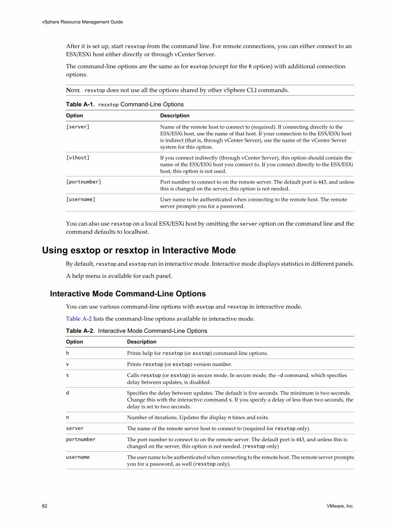
After it is set up, start resxtop from the command line. For remote connections, you can either connect to anESX/ESXi host either directly or through vCenter Server.
The command-line options are the same as for esxtop (except for the R option) with additional connectionoptions.
NOTE resxtop does not use all the options shared by other vSphere CLI commands.
Table A-1. resxtop Command-Line Options
Option Description
[server] Name of the remote host to connect to (required). If connecting directly to theESX/ESXi host, use the name of that host. If your connection to the ESX/ESXi hostis indirect (that is, through vCenter Server), use the name of the vCenter Serversystem for this option.
[vihost] If you connect indirectly (through vCenter Server), this option should contain thename of the ESX/ESXi host you connect to. If you connect directly to the ESX/ESXihost, this option is not used.
[portnumber] Port number to connect to on the remote server. The default port is 443, and unlessthis is changed on the server, this option is not needed.
[username] User name to be authenticated when connecting to the remote host. The remoteserver prompts you for a password.
You can also use resxtop on a local ESX/ESXi host by omitting the server option on the command line and thecommand defaults to localhost.
Using esxtop or resxtop in Interactive ModeBy default, resxtop and esxtop run in interactive mode. Interactive mode displays statistics in different panels.
A help menu is available for each panel.
Interactive Mode Command-Line OptionsYou can use various command-line options with esxtop and resxtop in interactive mode.
Table A-2 lists the command-line options available in interactive mode.
Table A-2. Interactive Mode Command-Line Options
Option Description
h Prints help for resxtop (or esxtop) command-line options.
v Prints resxtop (or esxtop) version number.
s Calls resxtop (or esxtop) in secure mode. In secure mode, the -d command, which specifiesdelay between updates, is disabled.
d Specifies the delay between updates. The default is five seconds. The minimum is two seconds.Change this with the interactive command s. If you specify a delay of less than two seconds, thedelay is set to two seconds.
n Number of iterations. Updates the display n times and exits.
server The name of the remote server host to connect to (required for resxtop only).
portnumber The port number to connect to on the remote server. The default port is 443, and unless this ischanged on the server, this option is not needed. (resxtop only)
username The user name to be authenticated when connecting to the remote host. The remote server promptsyou for a password, as well (resxtop only).
vSphere Resource Management Guide
82 VMware, Inc.

Table A-2. Interactive Mode Command-Line Options (Continued)
Option Description
a Show all statistics. This option overrides configuration file setups and shows all statistics. Theconfiguration file can be the default ~/.esxtop4rc configuration file or a user-defined configurationfile.
c<filename> Load a user-defined configuration file. If the -c option is not used, the default configurationfilename is ~/.esxtop4rc. Create your own configuration file, specifying a different filename, usingthe W single-key interactive command.
Common Statistics DescriptionSeveral statistics appear on the different panels while resxtop (or esxtop) is running in interactive mode. Thesestatistics are common across all four panels.
The Uptime line, found at the top of each of the four resxtop (or esxtop) panels, displays the current time, timesince last reboot, number of currently running worlds and load averages. A world is an ESX/ESXi VMkernelschedulable entity, similar to a process or thread in other operating systems.
Below that the load averages over the past one, five, and fifteen minutes appear. Load averages take intoaccount both running and ready-to-run worlds. A load average of 1.00 means that there is full utilization ofall physical CPUs. A load average of 2.00 means that the ESX/ESXi system might need twice as many physicalCPUs as are currently available. Similarly, a load average of 0.50 means that the physical CPUs on the ESX/ESXisystem are half utilized.
Statistics Columns and Order PagesYou can define the order of fields displayed in interactive mode.
If you press f, F, o, or O, the system displays a page that specifies the field order on the top line and shortdescriptions of the field contents. If the letter in the field string corresponding to a field is uppercase, the fieldis displayed. An asterisk in front of the field description indicates whether a field is displayed.
The order of the fields corresponds to the order of the letters in the string.
From the Field Select panel, you can:
n Toggle the display of a field by pressing the corresponding letter.
n Move a field to the left by pressing the corresponding uppercase letter.
n Move a field to the right by pressing the corresponding lowercase letter.
Interactive Mode Single-Key CommandsWhen running in interactive mode, resxtop (or esxtop) recognizes several single-key commands.
All interactive mode panels recognize the commands listed in Table A-3. The command to specify the delaybetween updates is disabled if the s option is given on the command line. All sorting interactive commandssort in descending order.
Table A-3. Interactive Mode Single-Key Commands
Key Description
h or ? Displays a help menu for the current panel, giving a brief summary of commands, and the status of secure mode.
space Immediately updates the current panel.
^L Erases and redraws the current panel.
f or F Displays a panel for adding or removing statistics columns (fields) to or from the current panel.
o or O Displays a panel for changing the order of statistics columns on the current panel.
Appendix A Performance Monitoring Utilities: resxtop and esxtop
VMware, Inc. 83

Table A-3. Interactive Mode Single-Key Commands (Continued)
Key Description
# Prompts you for the number of statistics rows to display. Any value greater than 0 overrides automaticdetermination of the number of rows to show, which is based on window size measurement. If you change thisnumber in one resxtop (or esxtop) panel, the change affects all four panels.
s Prompts you for the delay between updates, in seconds. Fractional values are recognized down to microseconds.The default value is five seconds. The minimum value is two seconds. This command is not available in securemode.
W Write the current setup to an esxtop (or resxtop) configuration file. This is the recommended way to write aconfiguration file. The default filename is the one specified by -c option, or ~/.esxtop4rc if the -c option is notused. You can also specify a different filename on the prompt generated by this W command.
q Quit interactive mode.
c Switch to the CPU resource utilization panel.
m Switch to the memory resource utilization panel.
d Switch to the storage (disk) adapter resource utilization panel.
u Switch to storage (disk) device resource utilization screen.
v Switch to storage (disk) virtual machine resource utilization screen.
n Switch to the network resource utilization panel.
I Switch to the interrupt panel.
CPU PanelThe CPU panel displays server-wide statistics as well as statistics for individual world, resource pool, andvirtual machine CPU utilization.
Resource pools, running virtual machines, or other worlds are at times called groups. For worlds belongingto a virtual machine, statistics for the running virtual machine are displayed. All other worlds are logicallyaggregated into the resource pools that contain them.
Table A-4 discusses statistics displayed in this panel.
Table A-4. CPU Panel Statistics
Line Description
PCPU USED(%) A PCPU refers to a physical hardware execution context. This can be a physical CPU core ifhyperthreading is unavailable or disabled, or a logical CPU (LCPU or SMT thread) if hyperthreadingis enabled.PCPU USED(%) displays:n Percentage of CPU usage per PCPUn percentage of CPU usage averaged over all PCPUsCPU Usage (%USED) is the percentage of PCPU nominal frequency that was used since the lastscreen update. It equals the total sum of %USED for Worlds that ran on this PCPU.NOTE If a PCPU is running at frequency that is higher than its nominal (rated) frequency, then PCPUUSED(%) can be greater than 100%.
PCPU UTIL(%) A PCPU refers to a physical hardware execution context. This can be a physical CPU core ifhyperthreading is unavailable or disabled, or a logical CPU (LCPU or SMT thread) if hyperthreadingis enabled.PCPU UTIL(%) represents the percentage of real time that the PCPU was not idle (raw PCPUutilization) and it displays the percentage CPU utilization per PCPU, and the percentage CPUutilization averaged over all PCPUs.NOTE PCPU UTIL(%) might differ from PCPU USED(%) due to power management technologiesor hyperthreading.
vSphere Resource Management Guide
84 VMware, Inc.

Table A-4. CPU Panel Statistics (Continued)
Line Description
CCPU(%) Percentages of total CPU time as reported by the ESX service console. This field is not displayed ifyou are using ESXi.n us — Percentage user time.n sy — Percentage system time.n id — Percentage idle time.n wa — Percentage wait time.n cs/sec — Context switches per second recorded by the service console.
ID Resource pool ID or virtual machine ID of the running world’s resource pool or virtual machine, orworld ID of running world.
GID Resource pool ID of the running world’s resource pool or virtual machine.
NAME Name of running world’s resource pool or virtual machine, or name of running world.
NWLD Number of members in running world’s resource pool or virtual machine. If a Group is expandedusing the interactive command e (see interactive commands), then NWLD for all the resulting worldsis 1 (some resource pools like the console resource pool have only one member).
%STATE TIMES Set of CPU statistics made up of the following percentages. For a world, the percentages are apercentage of one physical CPU core.
%USED Percentage of physical CPU core cycles used by the resource pool, virtual machine, or world. %USEDmight depend on the frequency with which the CPU core is running. When running with lower CPUcore frequency, %USED can be smaller than %RUN. On CPUs which support turbo mode, CPUfrequency can also be higher than the nominal (rated) frequency, and %USED can be larger than%RUN.
%SYS Percentage of time spent in the ESX/ESXi VMkernel on behalf of the resource pool, virtual machine,or world to process interrupts and to perform other system activities. This time is part of the timeused to calculate %USED.
%WAIT Percentage of time the resource pool, virtual machine, or world spent in the blocked or busy waitstate. This percentage includes the percentage of time the resource pool, virtual machine, or worldwas idle.
%IDLE Percentage of time the resource pool, virtual machine, or world was idle. Subtract this percentagefrom %WAIT to see the percentage of time the resource pool, virtual machine, or world was waitingfor some event. The difference, %WAIT- %IDLE, of the VCPU worlds can be used to estimate guestI/O wait time. To find the VCPU worlds, use the single-key command e to expand a virtual machineand search for the world NAME starting with "vcpu". (Note that the VCPU worlds might wait forother events besides I/O events, so, this measurement is only an estimate.)
%RDY Percentage of time the resource pool, virtual machine, or world was ready to run, but was not beprovided CPU resources on which to execute.
%MLMTD (maxlimited)
Percentage of time the ESX/ESXi VMkernel deliberately did not run the resource pool, virtualmachine, or world because doing so would violate the resource pool, virtual machine, or world'slimit setting. Because the resource pool, virtual machine, or world is ready to run when it is preventedfrom running in this way, the %MLMTD (max limited) time is included in %RDY time.
%SWPWT Percentage of time a resource pool or world spends waiting for the ESX/ESXi VMkernel to swapmemory. The %SWPWT (swap wait) time is included in the %WAIT time.
EVENT COUNTS/s Set of CPU statistics made up of per second event rates. These statistics are for VMware internal useonly.
CPU ALLOC Set of CPU statistics made up of the following CPU allocation configuration parameters.
AMIN Resource pool, virtual machine, or world attribute Reservation.
AMAX Resource pool, virtual machine, or world attribute Limit. A value of -1 means unlimited.
ASHRS Resource pool, virtual machine, or world attribute Shares.
SUMMARY STATS Set of CPU statistics made up of the following CPU configuration parameters and statistics. Thesestatistics apply only to worlds and not to virtual machines or resource pools.
Appendix A Performance Monitoring Utilities: resxtop and esxtop
VMware, Inc. 85

Table A-4. CPU Panel Statistics (Continued)
Line Description
AFFINITY BITMASK
Bit mask showing the current scheduling affinity for the world.
HTSHARING Current hyperthreading configuration.
CPU The physical or logical processor on which the world was running when resxtop (or esxtop)obtained this information.
HTQ Indicates whether the world is currently quarantined or not. N means no and Y means yes.
TIMER/s Timer rate for this world.
%OVRLP Percentage of system time spent during scheduling of a resource pool, virtual machine, or world onbehalf of a different resource pool, virtual machine, or world while the resource pool, virtualmachine, or world was scheduled. This time is not included in %SYS. For example, if virtual machineA is currently being scheduled and a network packet for virtual machine B is processed by theESX/ESXi VMkernel, the time spent appears as %OVRLP for virtual machine A and %SYS for virtualmachine B.
%RUN Percentage of total time scheduled. This time does not account for hyperthreading and system time.On a hyperthreading enabled server, the %RUN can be twice as large as %USED.
%CSTP Percentage of time a resource pool spends in a ready, co-deschedule state.(Note: you might see this statistic displayed, but it is intended for VMware use only).
You can change the display using single-key commands as discussed in Table A-5.
Table A-5. CPU Panel Single-Key Commands
Command Description
e Toggles whether CPU statistics are displayed expanded or unexpanded.The expanded display includes CPU resource utilization statistics broken down by individual worldsbelonging to a resource pool or virtual machine. All percentages for the individual worlds are percentageof a single physical CPU.Consider these examples:n If the %Used by a resource pool is 30% on a two-way server, the resource pool is utilizing 30 percent
of two physical CPUs.n If the %Used by a world belonging to a resource pool is 30 percent on a two-way server, that world
is utilizing 30% of one physical CPU.
U Sorts resource pools, virtual machines, and worlds by the resource pool’s or virtual machine’s %Usedcolumn.
R Sorts resource pools, virtual machines, and worlds by the resource pool’s or virtual machine’s %RDYcolumn.
N Sorts resource pools, virtual machines, and worlds by the GID column. This is the default sort order.
V Displays virtual machine instances only.
L Changes the displayed length of the NAME column.
Memory PanelThe Memory panel displays server-wide and group memory utilization statistics. As on the CPU panel, groupscorrespond to resource pools, running virtual machines, or other worlds that are consuming memory.
The first line, found at the top of the Memory panel displays the current time, time since last reboot, numberof currently running worlds, and memory overcommitment averages. The memory overcommitment averagesover the past 1, 5, and 15 minutes appear. Memory overcommitment of 1.00 means a memory overcommit of100 percent. See “Memory Overcommitment,” on page 26.
vSphere Resource Management Guide
86 VMware, Inc.

Table A-6. Memory Panel Statistics
Field Description
PMEM (MB) Displays the machine memory statistics for the server. All numbers are in megabytes.
total Total amount of machine memory in the server.
cos Amount of machine memory allocated to the ESX service console.
vmk Amount of machine memory being used by the ESX/ESXiVMkernel.
other Amount of machine memory being used by everything other thanthe ESX service console and ESX/ESXi VMkernel.
free Amount of machine memory that is free.
VMKMEM (MB) Displays the machine memory statistics for the ESX/ESXi VMkernel. All numbers are inmegabytes.
managed Total amount of machine memory managed by the ESX/ESXiVMkernel.
min free Minimum amount of machine memory that the ESX/ESXiVMkernel aims to keep free.
rsvd Total amount of machine memory currently reserved by resourcepools.
ursvd Total amount of machine memory currently unreserved.
state Current machine memory availability state. Possible values arehigh, soft, hard and low. High means that the machine memoryis not under any pressure and low means that it is.
COSMEM (MB) Displays the memory statistics as reported by the ESX service console. All numbers are inmegabytes. This field is not displayed if you are using ESXi.
free Amount of idle memory.
swap_t Total swap configured.
swap_f Amount of swap free.
r/s is Rate at which memory is swapped in from disk.
w/s Rate at which memory is swapped to disk.
NUMA (MB) Displays the ESX/ESXi NUMA statistics. This line appears only if the ESX/ESXi host is runningon a NUMA server. All numbers are in megabytes.For each NUMA node in the server, two statistics are displayed:n The total amount of machine memory in the NUMA node that is managed by ESX/ESXi.n The amount of machine memory in the node that is currently free (in parentheses).
PSHARE (MB) Displays the ESX/ESXi page-sharing statistics. All numbers are in megabytes.
shared Amount of physical memory that is being shared.
common Amount of machine memory that is common across worlds.
saving Amount of machine memory that is saved because of pagesharing.
Appendix A Performance Monitoring Utilities: resxtop and esxtop
VMware, Inc. 87
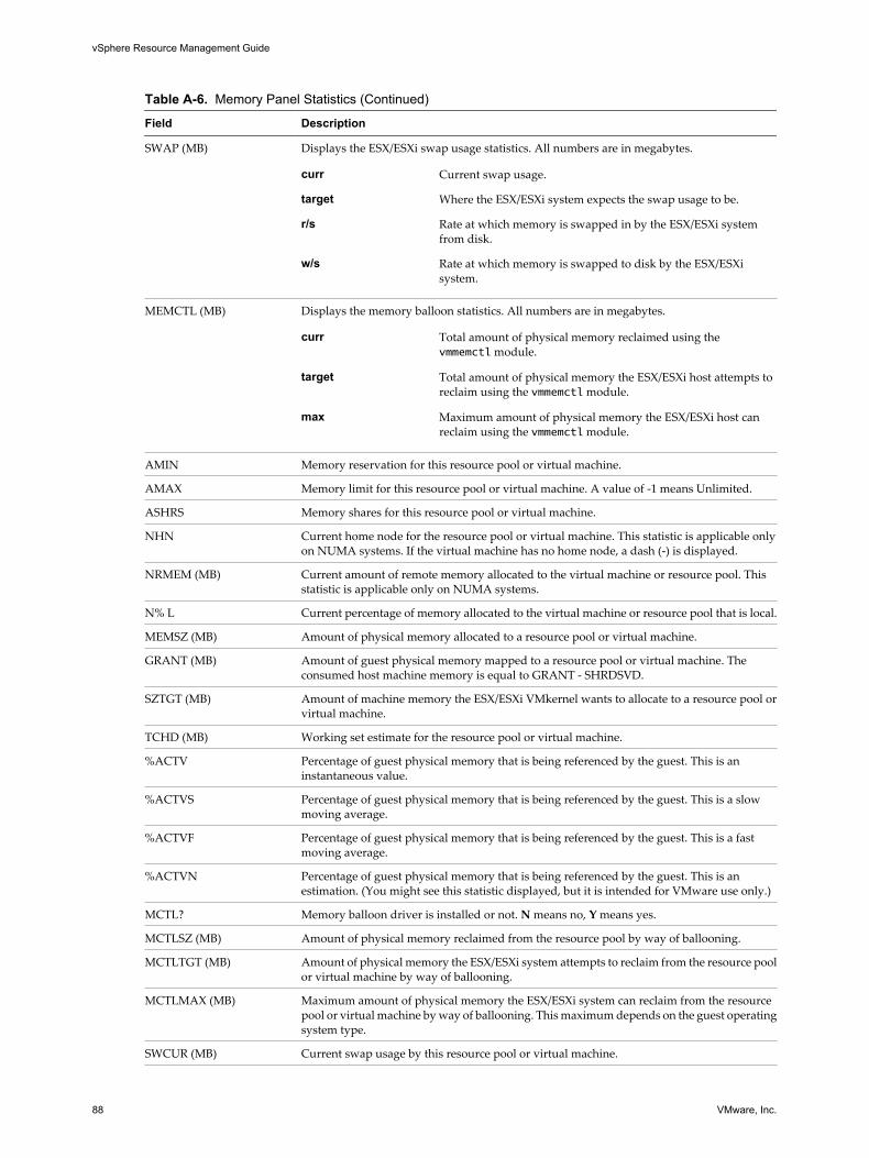
Table A-6. Memory Panel Statistics (Continued)
Field Description
SWAP (MB) Displays the ESX/ESXi swap usage statistics. All numbers are in megabytes.
curr Current swap usage.
target Where the ESX/ESXi system expects the swap usage to be.
r/s Rate at which memory is swapped in by the ESX/ESXi systemfrom disk.
w/s Rate at which memory is swapped to disk by the ESX/ESXisystem.
MEMCTL (MB) Displays the memory balloon statistics. All numbers are in megabytes.
curr Total amount of physical memory reclaimed using thevmmemctl module.
target Total amount of physical memory the ESX/ESXi host attempts toreclaim using the vmmemctl module.
max Maximum amount of physical memory the ESX/ESXi host canreclaim using the vmmemctl module.
AMIN Memory reservation for this resource pool or virtual machine.
AMAX Memory limit for this resource pool or virtual machine. A value of -1 means Unlimited.
ASHRS Memory shares for this resource pool or virtual machine.
NHN Current home node for the resource pool or virtual machine. This statistic is applicable onlyon NUMA systems. If the virtual machine has no home node, a dash (-) is displayed.
NRMEM (MB) Current amount of remote memory allocated to the virtual machine or resource pool. Thisstatistic is applicable only on NUMA systems.
N% L Current percentage of memory allocated to the virtual machine or resource pool that is local.
MEMSZ (MB) Amount of physical memory allocated to a resource pool or virtual machine.
GRANT (MB) Amount of guest physical memory mapped to a resource pool or virtual machine. Theconsumed host machine memory is equal to GRANT - SHRDSVD.
SZTGT (MB) Amount of machine memory the ESX/ESXi VMkernel wants to allocate to a resource pool orvirtual machine.
TCHD (MB) Working set estimate for the resource pool or virtual machine.
%ACTV Percentage of guest physical memory that is being referenced by the guest. This is aninstantaneous value.
%ACTVS Percentage of guest physical memory that is being referenced by the guest. This is a slowmoving average.
%ACTVF Percentage of guest physical memory that is being referenced by the guest. This is a fastmoving average.
%ACTVN Percentage of guest physical memory that is being referenced by the guest. This is anestimation. (You might see this statistic displayed, but it is intended for VMware use only.)
MCTL? Memory balloon driver is installed or not. N means no, Y means yes.
MCTLSZ (MB) Amount of physical memory reclaimed from the resource pool by way of ballooning.
MCTLTGT (MB) Amount of physical memory the ESX/ESXi system attempts to reclaim from the resource poolor virtual machine by way of ballooning.
MCTLMAX (MB) Maximum amount of physical memory the ESX/ESXi system can reclaim from the resourcepool or virtual machine by way of ballooning. This maximum depends on the guest operatingsystem type.
SWCUR (MB) Current swap usage by this resource pool or virtual machine.
vSphere Resource Management Guide
88 VMware, Inc.
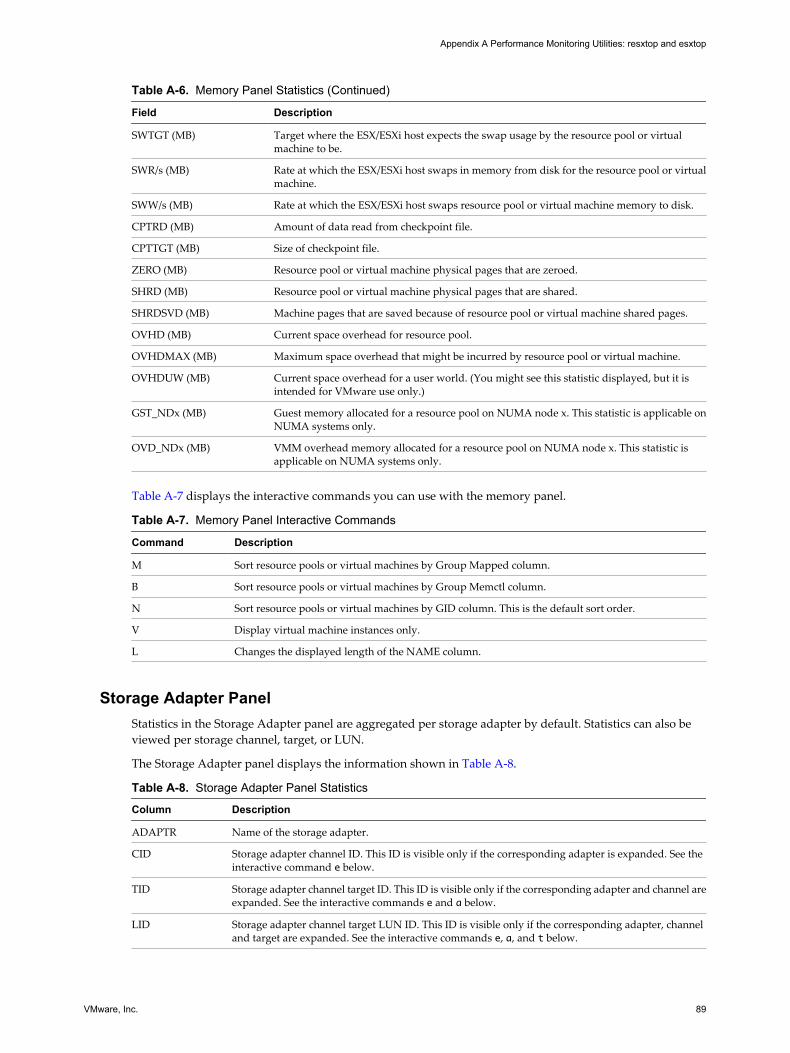
Table A-6. Memory Panel Statistics (Continued)
Field Description
SWTGT (MB) Target where the ESX/ESXi host expects the swap usage by the resource pool or virtualmachine to be.
SWR/s (MB) Rate at which the ESX/ESXi host swaps in memory from disk for the resource pool or virtualmachine.
SWW/s (MB) Rate at which the ESX/ESXi host swaps resource pool or virtual machine memory to disk.
CPTRD (MB) Amount of data read from checkpoint file.
CPTTGT (MB) Size of checkpoint file.
ZERO (MB) Resource pool or virtual machine physical pages that are zeroed.
SHRD (MB) Resource pool or virtual machine physical pages that are shared.
SHRDSVD (MB) Machine pages that are saved because of resource pool or virtual machine shared pages.
OVHD (MB) Current space overhead for resource pool.
OVHDMAX (MB) Maximum space overhead that might be incurred by resource pool or virtual machine.
OVHDUW (MB) Current space overhead for a user world. (You might see this statistic displayed, but it isintended for VMware use only.)
GST_NDx (MB) Guest memory allocated for a resource pool on NUMA node x. This statistic is applicable onNUMA systems only.
OVD_NDx (MB) VMM overhead memory allocated for a resource pool on NUMA node x. This statistic isapplicable on NUMA systems only.
Table A-7 displays the interactive commands you can use with the memory panel.
Table A-7. Memory Panel Interactive Commands
Command Description
M Sort resource pools or virtual machines by Group Mapped column.
B Sort resource pools or virtual machines by Group Memctl column.
N Sort resource pools or virtual machines by GID column. This is the default sort order.
V Display virtual machine instances only.
L Changes the displayed length of the NAME column.
Storage Adapter PanelStatistics in the Storage Adapter panel are aggregated per storage adapter by default. Statistics can also beviewed per storage channel, target, or LUN.
The Storage Adapter panel displays the information shown in Table A-8.
Table A-8. Storage Adapter Panel Statistics
Column Description
ADAPTR Name of the storage adapter.
CID Storage adapter channel ID. This ID is visible only if the corresponding adapter is expanded. See theinteractive command e below.
TID Storage adapter channel target ID. This ID is visible only if the corresponding adapter and channel areexpanded. See the interactive commands e and a below.
LID Storage adapter channel target LUN ID. This ID is visible only if the corresponding adapter, channeland target are expanded. See the interactive commands e, a, and t below.
Appendix A Performance Monitoring Utilities: resxtop and esxtop
VMware, Inc. 89

Table A-8. Storage Adapter Panel Statistics (Continued)
Column Description
NCHNS Number of channels.
NTGTS Number of targets.
NLUNS Number of LUNs.
NWDS Number of worlds.
BLKSZ Block size in bytes. This statistic is applicable only to LUNs.
AQLEN Storage adapter queue depth. Maximum number of ESX/ESXi VMkernel active commands that theadapter driver is configured to support.
LQLEN LUN queue depth. Maximum number of ESX/ESXi VMkernel active commands that the LUN isallowed to have.
%USD Percentage of queue depth (adapter, LUN or world) used by ESX/ESXi VMkernel active commands.
LOAD Ratio of ESX/ESXi VMkernel active commands plus ESX/ESXi VMkernel queued commands to queuedepth (adapter, LUN or world).
ACTV Number of commands in the ESX/ESXi VMkernel that are currently active.
QUED Number of commands in the ESX/ESXi VMkernel that are currently queued.
CMDS/s Number of commands issued per second.
READS/s Number of read commands issued per second.
WRITES/s Number of write commands issued per second.
MBREAD/s Megabytes read per second.
MBWRTN/s Megabytes written per second.
DAVG/cmd Average device latency per command, in milliseconds.
KAVG/cmd Average ESX/ESXi VMkernel latency per command, in milliseconds.
GAVG/cmd Average virtual machine operating system latency per command, in milliseconds.
DAVG/rd Average device read latency per read operation, in milliseconds.
KAVG/rd Average ESX/ESXi VMkernel read latency per read operation, in milliseconds.
GAVG/rd Average guest operating system read latency per read operation, in milliseconds.
DAVG/wr Average device write latency per write operation, in milliseconds.
KAVG/wr Average ESX/ESXi VMkernel write latency per write operation, in milliseconds.
GAVG/wr Average guest operating system write latency per write operation, in milliseconds.
QAVG/cmd Average queue latency per command, in milliseconds.
QAVG/rd Average queue latency per read operation, in milliseconds.
QAVG/wr Average queue latency per write operation, in milliseconds.
ABRTS/s Number of commands aborted per second.
RESETS/s Number of commands reset per second.
PAECMD/s The number of PAE (Physical Address Extension) commands per second.
PAECP/s The number of PAE copies per second.
SPLTCMD/s The number of split commands per second.
SPLTCP/s The number of split copies per second.
Table A-9 displays the interactive commands you can use with the storage adapter panel.
vSphere Resource Management Guide
90 VMware, Inc.

Table A-9. Storage Adapter Panel Interactive Commands
Command Description
e Toggles whether storage adapter statistics are displayed expanded or unexpanded. Allows viewingstorage resource utilization statistics broken down by individual channels belonging to an expandedstorage adapter. You are prompted for the adapter name.
P Toggles whether storage adapter statistics are displayed expanded or unexpanded. Allows viewingstorage resource utilization statistics broken down by paths belonging to an expanded storage adapter.Does not roll up to adapter statistics. You are prompted for the adapter name.
a Toggles whether storage channel statistics are displayed expanded or unexpanded. Allows viewingstorage resource utilization statistics broken down by individual targets belonging to an expandedstorage channel. You are prompted for the adapter name and the channel ID. The channel adapterneeds to be expanded before the channel itself can be expanded.
t Toggles whether storage target statistics are displayed in expanded or unexpanded mode. Allowsviewing storage resource utilization statistics broken down by individual paths belonging to anexpanded storage target. You are prompted for the adapter name, the channel ID, and the target ID.The target channel and adapter must be expanded before the target itself can be expanded.
r Sorts by READS/s column.
w Sorts by WRITES/s column.
R Sorts by MBREAD/s read column.
T Sorts by MBWRTN/s written column.
N Sorts first by ADAPTR column, then by CID column within each ADAPTR, then by TID column withineach CID, then by LID column within each TID, and finally by WID column within each LID. This isthe default sort order.
Storage Device PanelThe storage device panel displays server-wide storage utilization statistics.
By default, the information is grouped per storage device. You can also group the statistics per path, per world,or per partition.
Table A-10. Storage Device Panel Statistics
Column Description
DEVICE Name of the storage device.
PATH Path name. This name is visible only if the corresponding device is expanded to paths. See theinteractive command p below.
WORLD World ID. This ID is visible only if the corresponding device is expanded to worlds. See the interactivecommand e below. The world statistics are per world per device.
PARTITION Partition ID. This ID is visible only if the corresponding device is expanded to partitions. See interactivecommand t below.
NPH Number of paths.
NWD Number of worlds.
NPN Number of partitions.
SHARES Number of shares. This statistic is applicable only to worlds.
BLKSZ Block size in bytes.
NUMBLKS Number of blocks of the device.
DQLEN Storage device queue depth. This is the maximum number of ESX/ESXi VMkernel active commandsthat the device is configured to support.
Appendix A Performance Monitoring Utilities: resxtop and esxtop
VMware, Inc. 91
Table A-10. Storage Device Panel Statistics (Continued)
Column Description
WQLEN World queue depth. This is the maximum number of ESX/ESXi VMkernel active commands that theworld is allowed to have. This is a per device maximum for the world. It is valid only if thecorresponding device is expanded to worlds.
ACTV Number of commands in the ESX/ESXi VMkernel that are currently active. This statistic is applicableonly to worlds and devices.
QUED Number of commands in the ESX/ESXi VMkernel that are currently queued. This statistic is applicableonly to worlds and devices.
%USD Percentage of the queue depth used by ESX/ESXi VMkernel active commands. This statistic isapplicable only to worlds and devices.
LOAD Ratio of ESX/ESXi VMkernel active commands plus ESX/ESXi VMkernel queued commands to queuedepth. This statistic is applicable only to worlds and devices.
CMDS/s Number of commands issued per second.
READS/s Number of read commands issued per second.
WRITES/s Number of write commands issued per second.
MBREAD/s Megabytes read per second.
MBWRTN/s Megabytes written per second.
DAVG/cmd Average device latency per command in milliseconds.
KAVG/cmd Average ESX/ESXi VMkernel latency per command in milliseconds.
GAVG/cmd Average guest operating system latency per command in milliseconds.
QAVG/cmd Average queue latency per command in milliseconds.
DAVG/rd Average device read latency per read operation in milliseconds.
KAVG/rd Average ESX/ESXi VMkernel read latency per read operation in milliseconds.
GAVG/rd Average guest operating system read latency per read operation in milliseconds.
QAVG/rd Average queue read latency per read operation in milliseconds.
DAVG/wr Average device write latency per write operation in milliseconds.
KAVG/wr Average ESX/ESXi VMkernel write latency per write operation in milliseconds.
GAVG/wr Average guest operating system write latency per write operation in milliseconds.
QAVG/wr Average queue write latency per write operation in milliseconds.
ABRTS/s Number of commands aborted per second.
RESETS/s Number of commands reset per second.
PAECMD/s Number of PAE commands per second. This statistic is applicable only to paths.
PAECP/s Number of PAE copies per second. This statistic is applicable only to paths.
SPLTCMD/s Number of split commands per second. This statistic is applicable only to paths.
SPLTCP/s Number of split copies per second. This statistic is applicable only to paths.
Table A-11 displays the interactive commands you can use with the storage device panel.
vSphere Resource Management Guide
92 VMware, Inc.

Table A-11. Storage Device Panel Interactive Commands
Command Description
e Expand or roll up storage world statistics. This command allows you to view storage resource utilizationstatistics separated by individual worlds belonging to an expanded storage device. You are promptedfor the device name. The statistics are per world per device.
p Expand or roll up storage path statistics. This command allows you to view storage resource utilizationstatistics separated by individual paths belonging to an expanded storage device. You are prompted forthe device name.
t Expand or roll up storage partition statistics. This command allows you to view storage resourceutilization statistics separated by individual partitions belonging to an expanded storage device. Youare prompted for the device name.
r Sort by READS/s column.
w Sort by WRITES/s column.
R Sort by MBREAD/s column.
T Sort by MBWRTN column.
N Sort first by DEVICE column, then by PATH, WORLD, and PARTITION column. This is the default sortorder.
L Changes the displayed length of the DEVICE column.
Virtual Machine Storage PanelThis panel displays virtual machine-centric storage statistics.
By default, statistics are aggregated on a per-resource-pool basis. One virtual machine has one correspondingresource pool, so the panel really displays statistics on a per-virtual-machine basis. You can also view statisticson a per-world, or a per-world-per-device basis.
Table A-12. Virtual Machine Storage Panel Statistics
Column Description
ID Resource pool ID of the running world’s resource pool or the world ID of the running world.
GID Resource pool ID of running world’s resource pool.
NAME Name of running world’s resource pool or name of the running world.
Device Storage device name. This name is visible only if corresponding world is expanded to devices. See theinteractive command I below.
NWD Number of worlds.
NDV The number of devices. This number is valid only if the corresponding resource pool is expanded toworlds
SHARES Number of shares. This statistic is only applicable to worlds. It is valid only if the corresponding resourcepool is expanded to worlds
BLKSZ Block size in bytes. It is valid only if the corresponding world is expanded to devices.
NUMBLKS Number of blocks of the device. It is valid only if the corresponding world is expanded to devices.
DQLEN Storage device queue depth. This is the maximum number of ESX/ESXi VMkernel active commandsthat the device is configured to support. The displayed number is valid only if the corresponding worldis expanded to devices.
WQLEN World queue depth. This column displays the maximum number of ESX/ESXi VMkernel activecommands that the world is allowed to have. The number is valid only if the corresponding world isexpanded to devices. This is a per device maximum for the world.
ACTV Number of commands in the ESX/ESXi VMkernel that are currently active. This number is applicableonly to worlds and devices.
Appendix A Performance Monitoring Utilities: resxtop and esxtop
VMware, Inc. 93
Table A-12. Virtual Machine Storage Panel Statistics (Continued)
Column Description
QUED Number of commands in the ESX/ESXi VMkernel that are currently queued. This number is applicableonly to worlds and devices.
%USD Percentage of queue depth used by ESX/ESXi VMkernel active commands. This number is applicableonly to worlds and devices.
LOAD Ratio of ESX/ESXi VMkernel active commands plus ESX/ESXi VMkernel queued commands to queuedepth. This number is applicable only to worlds and devices.
CMDS/s Number of commands issued per second.
READS/s Number of read commands issued per second.
WRITES/s Number of write commands issued per second.
MBREAD/s Megabytes read per second.
MBWRTN/s Megabytes written per second.
DAVG/cmd Average device latency per command in milliseconds.
KAVG/cmd Average ESX/ESXi VMkernel latency per command in milliseconds.
GAVG/cmd Average guest operating system latency per command in milliseconds.
QAVG/cmd Average queue latency per command in milliseconds.
DAVG/rd Average device read latency per read operation in milliseconds.
KAVG/rd Average ESX/ESXi VMkernel read latency per read operation in milliseconds.
GAVG/rd Average guest operating system read latency per read operation in milliseconds.
QAVG/rd Average queue read latency per read operation in milliseconds.
DAVG/wr Average device write latency per write operation in milliseconds.
KAVG/wr Average ESX/ESXi VMkernel write latency per write operation in milliseconds.
GAVG/wr Average guest operating system write latency per write operation in milliseconds.
QAVG/wr Average queue write latency per write operation in milliseconds.
ABRTS/s Number of commands aborted per second in milliseconds.
RESETS/s Number of commands reset per second in milliseconds.
Table A-13 displays the interactive commands you can use with the virtual machine storage panel.
Table A-13. Virtual Machine Storage Panel Interactive Commands
Command Description
e Expand or roll up storage world statistics. Allows you to view storage resource utilization statisticsseparated by individual worlds belonging to a group. You are prompted to enter the group ID.The statistics are per world.
l Expand or roll up storage device, that is LUN, statistics. Allows you to view storage resourceutilization statistics separated by individual devices belonging to an expanded world. You areprompted to enter the world ID.
V Display virtual machine instances only.
r Sort by READS/s column.
w Sort by WRITES/s column.
R Sort by MBREAD/s column.
T Sort by MBWRTN/s column.
vSphere Resource Management Guide
94 VMware, Inc.

Table A-13. Virtual Machine Storage Panel Interactive Commands (Continued)
Command Description
N Sort first by virtual machine column, and then by WORLD column. This is the default sort order.
L Changes the displayed length of the NAME column.
Network PanelThe Network panel displays server-wide network utilization statistics.
Statistics are arranged by port for each virtual network device configured. For physical network adapterstatistics, see the row corresponding to the port to which the physical network adapter is connected. Forstatistics on a virtual network adapter configured in a particular virtual machine, see the row correspondingto the port to which the virtual network adapter is connected.
Table A-14. Network Panel Statistics
Column Description
PORT-ID Virtual network device port ID.
UPLINK Y means the corresponding port is an uplink. N means it is not.
UP Y means the corresponding link is up. N means it is not.
SPEED Link speed in Megabits per second.
FDUPLX Y means the corresponding link is operating at full duplex. N means it is not.
USED-BY Virtual network device port user.
DTYP Virtual network device type. H means HUB and S means switch.
DNAME Virtual network device name.
PKTTX/s Number of packets transmitted per second.
PKTRX/s Number of packets received per second.
MbTX/s MegaBits transmitted per second.
MbRX/s MegaBits received per second.
%DRPTX Percentage of transmit packets dropped.
%DRPRX Percentage of receive packets dropped.
TEAM-PNIC Name of the physical NIC used for the team uplink.
Table A-15 displays the interactive commands you can use with the network panel.
Table A-15. Network Panel Interactive Commands
Command Description
T Sorts by Mb Tx column.
R Sorts by Mb Rx column.
t Sorts by Packets Tx column.
r Sorts by Packets Rx column.
N Sorts by PORT-ID column. This is the default sort order.
L Changes the displayed length of the DNAME column.
Appendix A Performance Monitoring Utilities: resxtop and esxtop
VMware, Inc. 95
Interrupt PanelThe interrupt panel displays information about the use of interrupt vectors.
Table A-16. Interrupt Panel Statistics
Column Description
VECTOR Interrupt vector ID.
COUNT/s Total number of interrupts per second. This value is cumulative of the count for every CPU.
COUNT_x Interrupts per second on CPU x.
TIME/int Average processing time per interrupt (in microseconds).
TIME_x Average processing time per interrupt on CPU x (in microseconds).
DEVICES Devices that use the interrupt vector. If the interrupt vector is not enabled for the device, its name isenclosed in angle brackets (< and >).
Using Batch ModeBatch mode allows you to collect and save resource utilization statistics in a file.
After you prepare for batch mode, you can use esxtop or resxtop in this mode.
Prepare for Batch ModeTo run in batch mode, you must first prepare for batch mode.
Procedure
1 Run resxtop (or esxtop) in interactive mode.
2 In each of the panels, select the columns you want.
3 Save this configuration to a file (by default ~/.esxtop4rc) using the W interactive command.
You can now use resxtop (or esxtop) in batch mode.
Use esxtop or resxtop in Batch ModeAfter you have prepared for batch mode, you can use esxtop or resxtop in this mode.
Procedure
1 Start resxtop (or esxtop) to redirect the output to a file.
For example:
esxtop -b > my_file.csv
The filename must have a .csv extension. The utility does not enforce this, but the post-processing toolsrequire it.
2 Process statistics collected in batch mode using tools such as Microsoft Excel and Perfmon.
In batch mode, resxtop (or esxtop) does not accept interactive commands. In batch mode, the utility runs untilit produces the number of iterations requested (see command-line option n, below, for more details), or untilyou end the process by pressing Ctrl+c.
vSphere Resource Management Guide
96 VMware, Inc.
Batch Mode Command-Line OptionsYou can use batch mode with command-line options.
The command-line options in Table A-17 are available in batch mode.
Table A-17. Command-Line Options in Batch Mode
Option Description
a Show all statistics. This option overrides configuration file setups and shows all statistics. Theconfiguration file can be the default ~/.esxtop4rc configuration file or a user-definedconfiguration file.
b Runs resxtop (or esxtop) in batch mode.
c <filename> Load a user-defined configuration file. If the -c option is not used, the default configurationfilename is ~/.esxtop4rc. Create your own configuration file, specifying a different filename, usingthe W single-key interactive command.
d Specifies the delay between statistics snapshots. The default is five seconds. The minimum is twoseconds. If a delay of less than two seconds is specified, the delay is set to two seconds.
n Number of iterations. resxtop (or esxtop) collects and saves statistics this number of times, andthen exits.
server The name of the remote server host to connect to (required, resxtop only).
portnumber The port number to connect to on the remote server. The default port is 443, and unless this ischanged on the server, this option is not needed. (resxtop only)
username The user name to be authenticated when connecting to the remote host. You are prompted by theremote server for a password, as well (resxtop only).
Using Replay ModeIn replay mode, esxtop replays resource utilization statistics collected using vm-support.
After you prepare for replay mode, you can use esxtop in this mode. See the vm-support man page.
In replay mode, esxtop accepts the same set of interactive commands as in interactive mode and runs until nomore snapshots are collected by vm-support to be read or until the requested number of iterations arecompleted.
Prepare for Replay ModeTo run in replay mode, you must prepare for replay mode.
Procedure
1 Run vm-support in snapshot mode on the ESX service console.
Use the following command.
vm-support -S -d duration -I interval
2 Unzip and untar the resulting tar file so that esxtop can use it in replay mode.
You can now use esxtop in replay mode.
Use esxtop in Replay ModeYou can use esxtop in replay mode.
You do not have to run replay mode on the ESX service console. Replay mode can be run to produce outputin the same style as batch mode (see the command-line option b, below).
Appendix A Performance Monitoring Utilities: resxtop and esxtop
VMware, Inc. 97

Procedure
u To activate replay mode, enter the following at the command-line prompt.
esxtop -R <vm-support_dir_path>
Replay Mode Command-Line OptionsYou can use replay mode with command-line options.
Table A-18 lists the command-line options available for esxtop replay mode.
Table A-18. Command-Line Options in Replay Mode
Option Description
R Path to the vm-support collected snapshot’s directory.
a Show all statistics. This option overrides configuration file setups and shows all statistics. Theconfiguration file can be the default ~/.esxtop4rc configuration file or a user-definedconfiguration file.
b Runs esxtop in Batch mode.
c<filename> Load a user-defined configuration file. If the -c option is not used, the default configurationfilename is ~/.esxtop4rc. Create your own configuration file and specify a different filenameusing the W single-key interactive command.
d Specifies the delay between panel updates. The default is five seconds. The minimum is twoseconds. If a delay of less than two seconds is specified, the delay is set to two seconds.
n Number of iterations esxtop updates the display this number of times and then exits.
vSphere Resource Management Guide
98 VMware, Inc.

Advanced Attributes BYou can set advanced attributes for hosts or individual virtual machines to help you customize resourcemanagement.
In most cases, adjusting the basic resource allocation settings (reservation, limit, shares) or accepting defaultsettings results in appropriate resource allocation. However, you can use advanced attributes to customizeresource management for a host or a specific virtual machine.
This appendix includes the following topics:
n “Set Advanced Host Attributes,” on page 99
n “Set Advanced Virtual Machine Attributes,” on page 101
Set Advanced Host AttributesYou can set advanced attributes for a host.
CAUTION VMware recommends that only advanced users set advanced host attributes. In most cases, thedefault settings produce the optimum result.
Procedure
1 In the vSphere Client inventory panel, select the host to customize.
2 Click the Configuration tab.
3 In the Software menu, click Advanced Settings.
4 In the Advanced Settings dialog box select the appropriate item (for example, CPU or Memory), and scrollin the right panel to find and change the attribute.
Advanced CPU AttributesYou can use the advanced CPU attributes to customize CPU resource usage.
Table B-1. Advanced CPU Attributes
Attribute Description
Power.CpuPolicy When you set this attribute to the default value of static, VMkernel does notdirectly set CPU power management states and only responds to requests fromthe BIOS. When you enable this policy (set to dynamic), VMkernel dynamicallyselects appropriate power management states based on current usage. This cansave power without degrading performance. Enabling this option on systemsthat do not support power management results in an error message.
VMware, Inc. 99
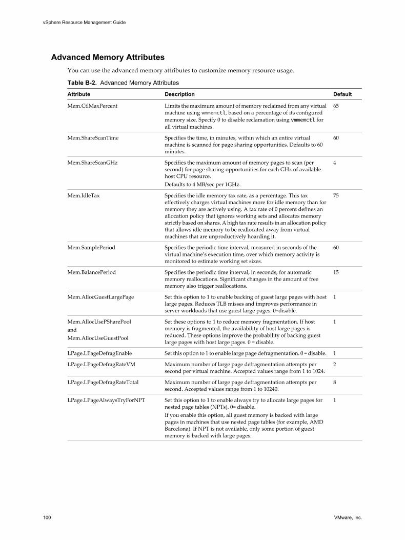
Advanced Memory AttributesYou can use the advanced memory attributes to customize memory resource usage.
Table B-2. Advanced Memory Attributes
Attribute Description Default
Mem.CtlMaxPercent Limits the maximum amount of memory reclaimed from any virtualmachine using vmmemctl, based on a percentage of its configuredmemory size. Specify 0 to disable reclamation using vmmemctl forall virtual machines.
65
Mem.ShareScanTime Specifies the time, in minutes, within which an entire virtualmachine is scanned for page sharing opportunities. Defaults to 60minutes.
60
Mem.ShareScanGHz Specifies the maximum amount of memory pages to scan (persecond) for page sharing opportunities for each GHz of availablehost CPU resource.Defaults to 4 MB/sec per 1GHz.
4
Mem.IdleTax Specifies the idle memory tax rate, as a percentage. This taxeffectively charges virtual machines more for idle memory than formemory they are actively using. A tax rate of 0 percent defines anallocation policy that ignores working sets and allocates memorystrictly based on shares. A high tax rate results in an allocation policythat allows idle memory to be reallocated away from virtualmachines that are unproductively hoarding it.
75
Mem.SamplePeriod Specifies the periodic time interval, measured in seconds of thevirtual machine’s execution time, over which memory activity ismonitored to estimate working set sizes.
60
Mem.BalancePeriod Specifies the periodic time interval, in seconds, for automaticmemory reallocations. Significant changes in the amount of freememory also trigger reallocations.
15
Mem.AllocGuestLargePage Set this option to 1 to enable backing of guest large pages with hostlarge pages. Reduces TLB misses and improves performance inserver workloads that use guest large pages. 0=disable.
1
Mem.AllocUsePSharePoolandMem.AllocUseGuestPool
Set these options to 1 to reduce memory fragmentation. If hostmemory is fragmented, the availability of host large pages isreduced. These options improve the probability of backing guestlarge pages with host large pages. 0 = disable.
1
LPage.LPageDefragEnable Set this option to 1 to enable large page defragmentation. 0 = disable. 1
LPage.LPageDefragRateVM Maximum number of large page defragmentation attempts persecond per virtual machine. Accepted values range from 1 to 1024.
2
LPage.LPageDefragRateTotal Maximum number of large page defragmentation attempts persecond. Accepted values range from 1 to 10240.
8
LPage.LPageAlwaysTryForNPT Set this option to 1 to enable always try to allocate large pages fornested page tables (NPTs). 0= disable.If you enable this option, all guest memory is backed with largepages in machines that use nested page tables (for example, AMDBarcelona). If NPT is not available, only some portion of guestmemory is backed with large pages.
1
vSphere Resource Management Guide
100 VMware, Inc.
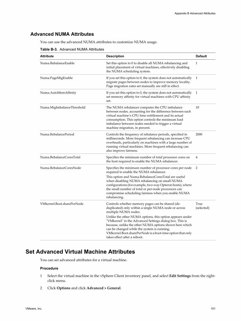
Advanced NUMA AttributesYou can use the advanced NUMA attributes to customize NUMA usage.
Table B-3. Advanced NUMA Attributes
Attribute Description Default
Numa.RebalanceEnable Set this option to 0 to disable all NUMA rebalancing andinitial placement of virtual machines, effectively disablingthe NUMA scheduling system.
1
Numa.PageMigEnable If you set this option to 0, the system does not automaticallymigrate pages between nodes to improve memory locality.Page migration rates set manually are still in effect.
1
Numa.AutoMemAffinity If you set this option to 0, the system does not automaticallyset memory affinity for virtual machines with CPU affinityset.
1
Numa.MigImbalanceThreshold The NUMA rebalancer computes the CPU imbalancebetween nodes, accounting for the difference between eachvirtual machine’s CPU time entitlement and its actualconsumption. This option controls the minimum loadimbalance between nodes needed to trigger a virtualmachine migration, in percent.
10
Numa.RebalancePeriod Controls the frequency of rebalance periods, specified inmilliseconds. More frequent rebalancing can increase CPUoverheads, particularly on machines with a large number ofrunning virtual machines. More frequent rebalancing canalso improve fairness.
2000
Numa.RebalanceCoresTotal Specifies the minimum number of total processor cores onthe host required to enable the NUMA rebalancer.
4
Numa.RebalanceCoresNode Specifies the minimum number of processor cores per noderequired to enable the NUMA rebalancer.This option and Numa.RebalanceCoresTotal are usefulwhen disabling NUMA rebalancing on small NUMAconfigurations (for example, two-way Opteron hosts), wherethe small number of total or per-node processors cancompromise scheduling fairness when you enable NUMArebalancing.
2
VMkernel.Boot.sharePerNode Controls whether memory pages can be shared (de-duplicated) only within a single NUMA node or acrossmultiple NUMA nodes.Unlike the other NUMA options, this option appears under"VMkernel" in the Advanced Settings dialog box. This isbecause, unlike the other NUMA options shown here whichcan be changed while the system is running,VMkernel.Boot.sharePerNode is a boot-time option that onlytakes effect after a reboot.
True(selected)
Set Advanced Virtual Machine AttributesYou can set advanced attributes for a virtual machine.
Procedure
1 Select the virtual machine in the vSphere Client inventory panel, and select Edit Settings from the right-click menu.
2 Click Options and click Advanced > General.
Appendix B Advanced Attributes
VMware, Inc. 101
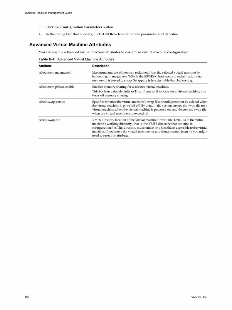
3 Click the Configuration Parameters button.
4 In the dialog box that appears, click Add Row to enter a new parameter and its value.
Advanced Virtual Machine AttributesYou can use the advanced virtual machine attributes to customize virtual machine configuration.
Table B-4. Advanced Virtual Machine Attributes
Attribute Description
sched.mem.maxmemctl Maximum amount of memory reclaimed from the selected virtual machine byballooning, in megabytes (MB). If the ESX/ESXi host needs to reclaim additionalmemory, it is forced to swap. Swapping is less desirable than ballooning.
sched.mem.pshare.enable Enables memory sharing for a selected virtual machine.This boolean value defaults to True. If you set it to False for a virtual machine, thisturns off memory sharing.
sched.swap.persist Specifies whether the virtual machine’s swap files should persist or be deleted whenthe virtual machine is powered off. By default, the system creates the swap file for avirtual machine when the virtual machine is powered on, and deletes the swap filewhen the virtual machine is powered off.
sched.swap.dir VMFS directory location of the virtual machine's swap file. Defaults to the virtualmachine's working directory, that is, the VMFS directory that contains itsconfiguration file. This directory must remain on a host that is accessible to the virtualmachine. If you move the virtual machine (or any clones created from it), you mightneed to reset this attribute.
vSphere Resource Management Guide
102 VMware, Inc.

Index
Aadmission control
CPU 23resource pools 41with expandable resource pools 42
advanced attributesCPU 99hosts 99memory 100NUMA 101virtual machines 101
alarms 66AMD Opteron-based systems 49, 73, 76, 101applications
CPU-bound 18single-threaded 18
automation modes, virtual machines 51
Bballooning, memory 31Baseboard Management Controller (BMC) 63batch mode
command-line options 97preparing for 96
CCPU
admission control 23advanced attributes 99managing allocation 17, 18overcommitment 17
CPU affinityhyperthreading 21NUMA nodes 78potential issues 23
CPU panelesxtop 84resxtop 84
CPU power efficiency 24CPU virtualization
hardware-assisted 18software-based 17
CPU-bound applications 18custom automation mode 51
DDPM
and admission control 16automation level 65enabling 64Last Time Exited Standby 65monitoring 66overrides 65threshold 65
DRSdisabling 51fully automated 50group power on 46information 68initial placement 45, 46load balancing 45manual 50migration 45migration recommendations 48partially automated 50single virtual machine power on 46virtual machine migration 47VMotion network 49
DRS actions, history 69DRS Cluster Summary tab 67DRS clusters
adding managed hosts 55adding unmanaged hosts 55as resource providers 9creating 50general information 67managing resources with 53prerequisites 49processor compatibility 49shared storage 49shared VMFS volume 49validity 58viewing information 67
DRS faults 69DRS migration threshold 48DRS recommendations
priority 69reasons 69
DRS Resource Distribution Chart 68
VMware, Inc. 103
DRS rulescreating 53deleting 54disabling 54editing 54
DRS tabFaults page 70History page 71Recommendations page 69using 69
DRS Troubleshooting Guide 70dual-processor virtual machine 17dynamic load balancing, NUMA 75Dynamic Voltage and Frequency Scaling
(DVFS) 24
Eeducational support 7Enhanced VMotion Compatibility (EVC) 18, 49,
50, 67entering maintenance mode 57ESX/ESXi
memory allocation 30memory reclamation 31
esxtopbatch mode 96common statistics description 83CPU panel 84interactive mode 82interactive mode command-line options 82interactive mode single-key commands 83interrupt panel 96memory panel 86network panel 95order pages 83performance monitoring 81replay mode 97statistics column 83storage adapter panel 89storage device panel 91virtual machine storage panel 93
Exit Standby Error 66expandable reservations, example 42
Ffully automated DRS 50
Ggrafted, resource pool 55group power on 46
Hhome nodes, NUMA 75host-local swap
DRS cluster 33standalone host 33
hostsadding to DRS clusters 55advanced attributes 99as resource providers 9entering maintenance mode 57removing from a DRS cluster 56
hyperthreadingand ESX/ESXi 21core sharing modes 22CPU affinity 21disabling 19disabling quarantining 99enabling 21performance implications 20quarantining 22server configuration for 21
hyperthreading modes 21
IIBM Enterprise X-Architecture 76idle memory tax 31iLO, configuring 63initial placement, NUMA 75Intelligent Platform Management Interface (IPMI),
configuring 63invalid DRS clusters 61
LLast Time Exited Standby 65limit 12load balancing, virtual machines 47logical processors 19LPage.LPageAlwaysTryForNPT 100LPage.LPageDefragEnable 100LPage.LPageDefragRateTotal 100LPage.LPageDefragRateVM 100
Mmaintenance mode, entering 57manual DRS 50Mem.AllocGuestLargePage 100Mem.AllocUseGuestPool 100Mem.AllocUsePSharePool 100Mem.BalancePeriod 100Mem.CtlMaxPercent 100Mem.IdleTax 31, 100Mem.SamplePeriod 30, 100Mem.ShareScanGHz 34, 100
vSphere Resource Management Guide
104 VMware, Inc.

Mem.ShareScanTime 34, 100memory
advanced attributes 100balloon driver 31managing allocation 25, 28overcommitment 26, 33overhead 25overhead, understanding 29reclaiming unused 31service console 25sharing 26sharing across virtual machines 34virtual machines 31virtualization 25
memory affinity, NUMA nodes 78memory idle tax 31memory usage 35memory virtualization
hardware-assisted 27software-based 27
migration recommendations 48monitoring software 66multicore processors 19
NNUMA
advanced attributes 101AMD Opteron-based systems 76CPU affinity 78description 73dynamic load balancing 75home nodes 75home nodes and initial placement 75IBM Enterprise X-Architecture 76manual controls 77memory page sharing 75optimization algorithms 75page migration 75scheduling 74supported architectures 76transparent page sharing 75
Numa.AutoMemAffinity 101Numa.MigImbalanceThreshold 101Numa.PageMigEnable 101Numa.RebalanceCoresNode 101Numa.RebalanceCoresTotal 101Numa.RebalanceEnable 101Numa.RebalancePeriod 101
OOpteron 76overcommitted DRS clusters 60
overhead memory 25
Ppage migration, NUMA 75parent resource pool 37partially automated DRS 50performance, CPU-bound applications 18performance monitoring 81physical memory usage 29physical processors 19power on, single virtual machine 46Power.CpuPolicy 24, 99processor-specific behavior 18
Qquarantining, hyperthreading 22
Rred DRS clusters 61replay mode
command-line options 98preparing for 97
reservation 11resource allocation settings
changing 12limit 12reservation 11shares 11suggestions 12
resource consumers 10resource management
customizing 99defined 9goals 10information 13
resource poolsadding virtual machines 40admission control 41advantages 38attributes 39changing attributes of 40creating 39, 40grafted 55parent 37removing virtual machines 41root resource pool 37siblings 37
resource providers 9resource types 9resxtop
batch mode 96common statistics description 83CPU panel 84
Index
VMware, Inc. 105

interactive mode 82interactive mode command-line options 82interactive mode single-key commands 83interrupt panel 96memory panel 86network panel 95options 81order pages 83performance monitoring 81statistics column 83storage adapter panel 89storage device panel 91virtual machine storage panel 93
root resource pool 37
Ssched.mem.maxmemctl 31, 102sched.mem.pshare.enable 102sched.swap.dir 102sched.swap.persist 102server configuration for hyperthreading 21service console, memory use 25shares 11sharing memory 26siblings 37single virtual machine power on 46single-processor virtual machine 17single-threaded applications 18SMP virtual machines 18standby mode, Last Time Exited Standby 65statistics, esxtop 83statistics, resxtop 83swap file
deleting 34location 33using 32
swap space 33System Resource Allocation Table (SRAT) 74
Ttechnical support 7
Uupdated information 5
Vvalid DRS clusters 58vCenter Server events 66virtual machine affinity 53virtual machine anti-affinity 53Virtual Machine File System (VMFS) 49, 102
virtual machinesadding to DRS clusters 56adding to resource pools 40advanced attributes 101as resource consumers 10assigning to a specific processor 23automation modes 51configuration file 49memory 25, 31migration 47monitor 27number of virtual processors 18overhead memory 30removing from a DRS cluster 57removing from resource pools 41sharing memory across 34
vMA 81VMFS (Virtual Machine File System) 49, 102VMkernel.Boot.sharePerNode 75, 101VMM 25, 27vmmemctl
Mem.CtlMaxPercent 100sched.mem.maxmemctl 102
VMware HA 13, 50, 53, 57, 67vSphere CLI 81vSphere Client 13, 15, 19, 29, 67, 69vSphere Management Assistant 81vSphere SDK 19
Wwake protocols 62Wake-on-LAN (WOL), testing 64working set size 30
Yyellow DRS clusters 60
vSphere Resource Management Guide
106 VMware, Inc.