vsx 5000, vsx 7000s - national institute of standards and
TRANSCRIPT
© 2007 Polycom, Inc. – This document may be freely reproduced and distributed whole and intact including this Copyright Notice.
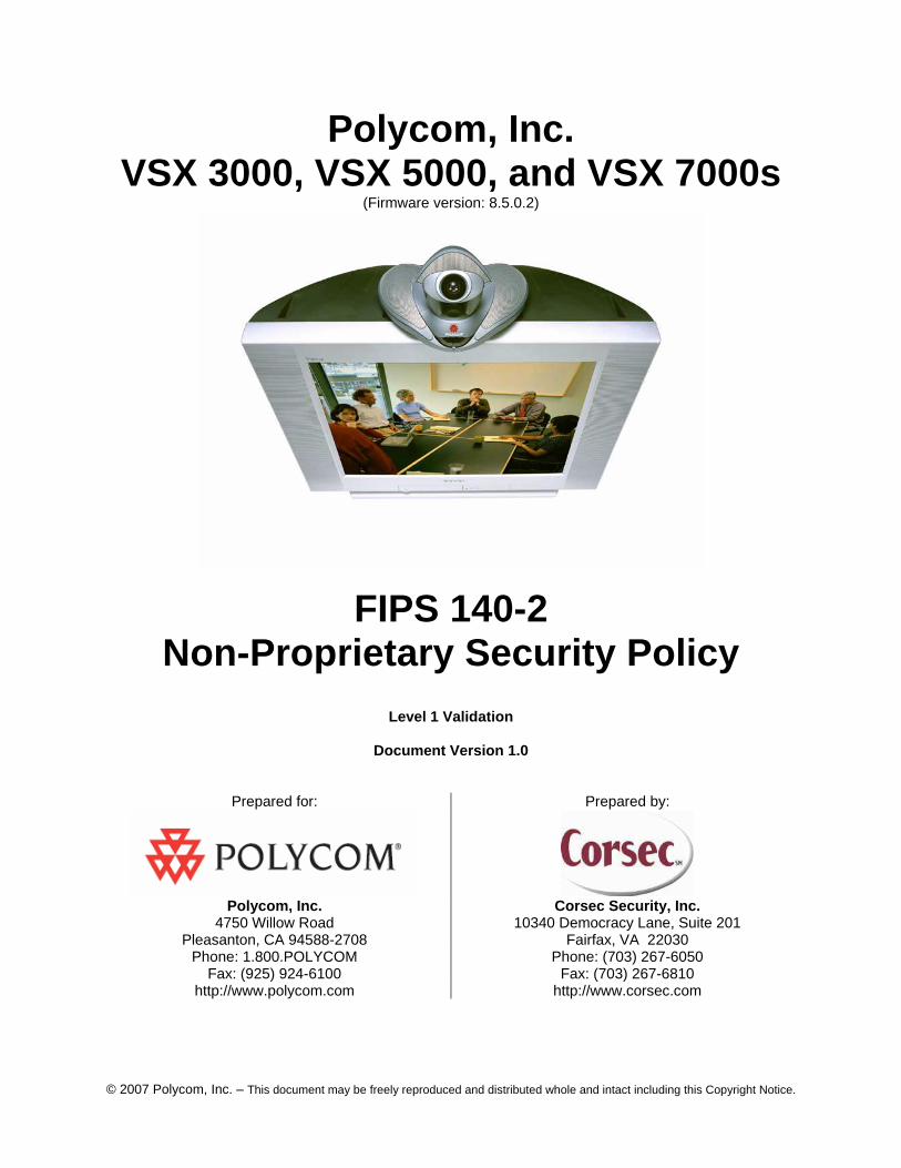
Polycom, Inc. VSX 3000, VSX 5000, and VSX 7000s
(Firmware version: 8.5.0.2)
FIPS 140-2 Non-Proprietary Security Policy
Level 1 Validation
Document Version 1.0
Prepared for: Prepared by:
Polycom, Inc. Corsec Security, Inc.
4750 Willow Road Pleasanton, CA 94588-2708
10340 Democracy Lane, Suite 201 Fairfax, VA 22030
Phone: 1.800.POLYCOM Phone: (703) 267-6050 Fax: (925) 924-6100 Fax: (703) 267-6810
http://www.polycom.com http://www.corsec.com
Non-Proprietary Security Policy, Version 1.0 June 15, 2007
Polycom VSX 3000, VSX 5000, and VSX 7000s Page 2 of 23 © 2007 Polycom, Inc. - This document may be freely reproduced and distributed whole and intact including this Copyright Notice.
Revision History
Version Modification Date Modified By Description of Changes
1.0 2007-06-15 Xiaoyu Ruan Release version.
Non-Proprietary Security Policy, Version 1.0 June 15, 2007
Polycom VSX 3000, VSX 5000, and VSX 7000s Page 3 of 23 © 2007 Polycom, Inc. - This document may be freely reproduced and distributed whole and intact including this Copyright Notice.
Table of Contents
0 INTRODUCTION ...............................................................................................................................................5 0.1 PURPOSE.........................................................................................................................................................5 0.2 REFERENCES...................................................................................................................................................5 0.3 DOCUMENT ORGANIZATION ...........................................................................................................................5
1 VSX 3000, VSX 5000, AND VSX 7000S.............................................................................................................6 1.1 OVERVIEW......................................................................................................................................................6 1.2 MODULE SPECIFICATIONS..............................................................................................................................6 1.3 MODULE INTERFACES....................................................................................................................................8 1.4 ROLES AND SERVICES...................................................................................................................................16
1.4.1 Crypto-Officer Role .............................................................................................................................16 1.4.2 User Role .............................................................................................................................................16 1.4.3 Authentication......................................................................................................................................17
1.5 PHYSICAL SECURITY ....................................................................................................................................17 1.6 OPERATIONAL ENVIRONMENT......................................................................................................................17 1.7 CRYPTOGRAPHIC KEY MANAGEMENT..........................................................................................................17
1.7.1 Key Generation....................................................................................................................................18 1.7.2 Key Input/Output .................................................................................................................................18 1.7.3 Key Storage..........................................................................................................................................19 1.7.4 Key Zeroization....................................................................................................................................19
1.8 SELF-TESTS..................................................................................................................................................19 1.9 DESIGN ASSURANCE.....................................................................................................................................19
2 SECURE OPERATION....................................................................................................................................20 2.1 CRYPTO-OFFICER GUIDANCE .......................................................................................................................20
2.1.1 Initialization.........................................................................................................................................20 2.1.2 Management ........................................................................................................................................20
2.2 USER GUIDANCE ..........................................................................................................................................21
3 ACRONYMS......................................................................................................................................................23
Table of Figures
FIGURE 1 - VSX 3000.....................................................................................................................................................6 FIGURE 2 - VSX 5000.....................................................................................................................................................7 FIGURE 3 - VSX 7000S...................................................................................................................................................7 FIGURE 4 - VSX 7000E...................................................................................................................................................7 FIGURE 5 - VSX 8000.....................................................................................................................................................8 FIGURE 6 - VSX 3000 CONNECTOR PANEL ....................................................................................................................9 FIGURE 7 - VSX 5000 BACK PANEL .............................................................................................................................10 FIGURE 8 - VSX 7000E BACK PANEL ...........................................................................................................................12 FIGURE 9 - VSX 7000S BACK PANEL ...........................................................................................................................13 FIGURE 10 - VSX 8000 BACK PANEL ...........................................................................................................................15
Table of Tables
TABLE 1 - SECURITY LEVEL PER FIPS 140-2 SECTION...................................................................................................8 TABLE 2 - MAPPING OF FIPS 140-2 LOGICAL INTERFACES TO VSX 3000, VSX 5000, AND VSX 7000S INTERFACES...9 TABLE 3 - MAPPING OF FIPS 140-2 LOGICAL INTERFACES TO VSX 5000 INTERFACES................................................10
Non-Proprietary Security Policy, Version 1.0 June 15, 2007
Polycom VSX 3000, VSX 5000, and VSX 7000s Page 4 of 23 © 2007 Polycom, Inc. - This document may be freely reproduced and distributed whole and intact including this Copyright Notice.
TABLE 4 - MAPPING OF FIPS 140-2 LOGICAL INTERFACES TO VSX 7000E INTERFACES..............................................12 TABLE 5 - MAPPING OF FIPS 140-2 LOGICAL INTERFACES TO VSX 7000S INTERFACES..............................................13 TABLE 6 - MAPPING OF FIPS 140-2 LOGICAL INTERFACES TO VSX 8000 INTERFACES................................................15 TABLE 7 - MAPPING OF CRYPTO-OFFICER’S SERVICES TO INPUTS, OUTPUTS, CRITICAL SECURITY PARAMETERS
(CSPS), AND ACCESS CONTROL...........................................................................................................................16 TABLE 8 - MAPPING OF USER’S SERVICES TO INPUTS, OUTPUTS, CSPS, AND ACCESS CONTROL.................................16 TABLE 9 - LIST OF CRYPTOGRAPHIC KEYS, CRYPTOGRAPHIC KEY COMPONENTS, AND CSPS .....................................17 TABLE 10 - LED/POWER BUTTON LIGHT DESCRIPTION...............................................................................................21 TABLE 11 - BRI NETWORK INTERFACE LEDS..............................................................................................................22 TABLE 12 - PRI NETWORK INTERFACE LEDS ..............................................................................................................22 TABLE 13 - V.35/RS-449/RS-530 NETWORK INTERFACE LEDS ..................................................................................22 TABLE 14 - ACRONYMS................................................................................................................................................23
Non-Proprietary Security Policy, Version 1.0 June 15, 2007
Polycom VSX 3000, VSX 5000, and VSX 7000s Page 5 of 23 © 2007 Polycom, Inc. - This document may be freely reproduced and distributed whole and intact including this Copyright Notice.
0 Introduction
0.1 Purpose
This is a non-proprietary Cryptographic Module Security Policy for the VSX 3000, VSX 5000, and VSX 7000s from Polycom, Inc.. This Security Policy describes how the VSX 3000, VSX 5000, and VSX 7000s meet the security requirements of FIPS 140-2 and how to run the module in a secure FIPS 140-2 mode. This policy was prepared as part of the Level 1 FIPS 140-2 validation of the module.
FIPS 140-2 (Federal Information Processing Standards Publication 140-2 – Security Requirements for Cryptographic Modules) details the U.S. Government requirements for cryptographic modules. More information about the FIPS 140-2 standard and validation program is available on the National Institute of Standards and Technology (NIST) Cryptographic Module Validation Program (CMVP) website at: http://csrc.nist.gov/cryptval/
The VSX 3000, VSX 5000, and VSX 7000s are referred to in this document as the VSX systems, the hardware modules, the cryptographic modules, or the modules.
0.2 References
This document deals only with operations and capabilities of the module in the technical terms of a FIPS 140-2 cryptographic module security policy. More information is available on the module from the following sources:
• The Polycom website (http://polycom.com) contains information on the full line of products from Polycom. • The CMVP website (http://csrc.nist.gov/cryptval/) contains contact information for answers to technical or
sales-related questions for the module.
0.3 Document Organization
The Security Policy document is one document in a FIPS 140-2 Submission Package. In addition to this document, the Submission Package contains:
• Vendor Evidence document • Finite State Machine • Other supporting documentation as additional references
This Security Policy and the other validation submission documentation were produced by Corsec Security, Inc. under contract to Polycom. With the exception of this Non-Proprietary Security Policy, the FIPS 140-2 Validation Documentation is proprietary to Polycom and is releasable only under appropriate non-disclosure agreements. For access to these documents, please contact Polycom.
Non-Proprietary Security Policy, Version 1.0 June 15, 2007
Polycom VSX 3000, VSX 5000, and VSX 7000s Page 6 of 23 © 2007 Polycom, Inc. - This document may be freely reproduced and distributed whole and intact including this Copyright Notice.
1 VSX 3000, VSX 5000, and VSX 7000s
1.1 Overview
Founded in 1990, Polycom is the only company delivering end-to-end rich media collaborative applications for voice, video, data and the web. Polycom has a wide range of products from desktop and mobile personal systems to room systems to the network core. Polycom’s full range of high-quality voice and video communications endpoints, video management software, web conferencing software, and multipoint conferencing enable organizations of all sizes to increase productivity and agility. Polycom delivers business value by cutting costs, simplifying system management, fostering real time collaboration and decision making, and improving relationships with employees, customers and partners.
The Polycom VSX products are state of the art video-conferencing nodes. These systems provide video-conferencing facilities using all the popular telecommunication protocols such as H.320 H.323, and Session Initiation Protocol (SIP) and include support of Integrated Services Digital Network (ISDN), Primary rate and Basic rate as well as serial interfaces for V.35, RS-499 and RS-530.
1.2 Module Specifications
The VSX systems feature a variety of models ranging from desktop systems (VSX 3000) to set top appliance systems (VSX 5000, VSX 7000s) to rack mounted systems (VSX 7000e, VSX 8000). All of the models provide top-performance video processing and feature high-performance BSP-15 processors from Equator with 128 MB SDRAM.
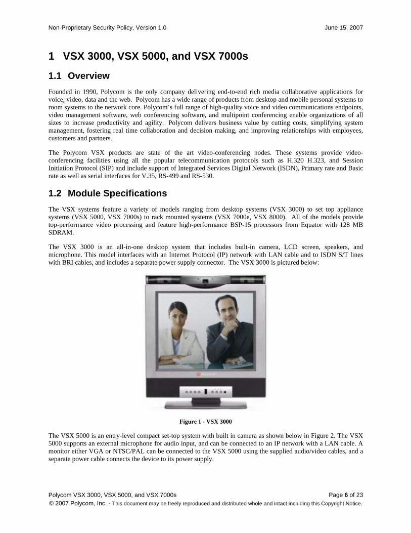
The VSX 3000 is an all-in-one desktop system that includes built-in camera, LCD screen, speakers, and microphone. This model interfaces with an Internet Protocol (IP) network with LAN cable and to ISDN S/T lines with BRI cables, and includes a separate power supply connector. The VSX 3000 is pictured below:
Figure 1 - VSX 3000
The VSX 5000 is an entry-level compact set-top system with built in camera as shown below in Figure 2. The VSX 5000 supports an external microphone for audio input, and can be connected to an IP network with a LAN cable. A monitor either VGA or NTSC/PAL can be connected to the VSX 5000 using the supplied audio/video cables, and a separate power cable connects the device to its power supply.
Non-Proprietary Security Policy, Version 1.0 June 15, 2007
Polycom VSX 3000, VSX 5000, and VSX 7000s Page 7 of 23 © 2007 Polycom, Inc. - This document may be freely reproduced and distributed whole and intact including this Copyright Notice.
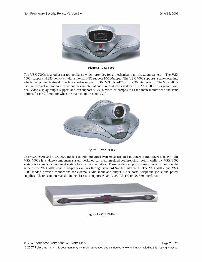
Figure 2 - VSX 5000
The VSX 7000s is another set-top appliance which provides for a mechanical pan, tilt, zoom camera. The VSX 7000s supports H.323 networks with a internal NIC support 10/100mbps.. The VSX 7000 supports a subwoofer into which the optional Network Interface Card to support ISDN, V.35, RS-499 or RS-530 interfaces. . The VSX 7000s uses an external microphone array and has an internal audio reproduction system. The VSX 7000s is standard with dual video display output support and can support VGA, S-video or composite as the main monitor and the same options for the 2nd monitor when the main monitor is not VGA.
Figure 3 - VSX 7000s
The VSX 7000e and VSX 8000 models are rack-mounted systems as depicted in Figure 4 and Figure 5 below. The VSX 7000e is a video component system designed for medium-sized conferencing rooms, while the VSX 8000 system is a compact component system for custom integrators. These models support connections with monitors the same as the VSX 7000s and third-party cameras through standard S-video interfaces. The VSX 7000e and VSX 8000 models provide connections for external audio input and output, LAN ports, telephone jacks, and power supplies. There is an internal slot in the chassis to support ISDN, V.35, RS-499 or RS-530 interfaces.
Figure 4 - VSX 7000e
Non-Proprietary Security Policy, Version 1.0 June 15, 2007
Polycom VSX 3000, VSX 5000, and VSX 7000s Page 8 of 23 © 2007 Polycom, Inc. - This document may be freely reproduced and distributed whole and intact including this Copyright Notice.
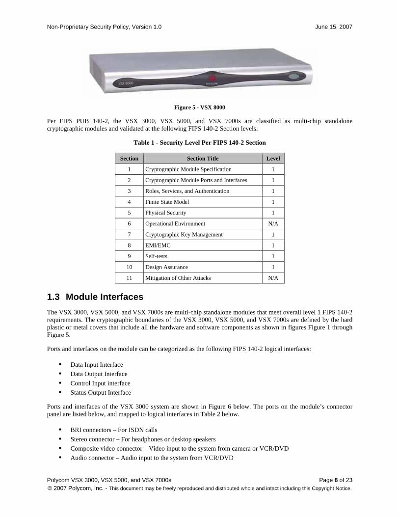
Figure 5 - VSX 8000
Per FIPS PUB 140-2, the VSX 3000, VSX 5000, and VSX 7000s are classified as multi-chip standalone cryptographic modules and validated at the following FIPS 140-2 Section levels:
Table 1 - Security Level Per FIPS 140-2 Section
Section Section Title Level
1 Cryptographic Module Specification 1
2 Cryptographic Module Ports and Interfaces 1
3 Roles, Services, and Authentication 1
4 Finite State Model 1
5 Physical Security 1
6 Operational Environment N/A
7 Cryptographic Key Management 1
8 EMI/EMC 1
9 Self-tests 1
10 Design Assurance 1
11 Mitigation of Other Attacks N/A
1.3 Module Interfaces
The VSX 3000, VSX 5000, and VSX 7000s are multi-chip standalone modules that meet overall level 1 FIPS 140-2 requirements. The cryptographic boundaries of the VSX 3000, VSX 5000, and VSX 7000s are defined by the hard plastic or metal covers that include all the hardware and software components as shown in figures Figure 1 through Figure 5.
Ports and interfaces on the module can be categorized as the following FIPS 140-2 logical interfaces:
• Data Input Interface
• Data Output Interface
• Control Input interface
• Status Output Interface
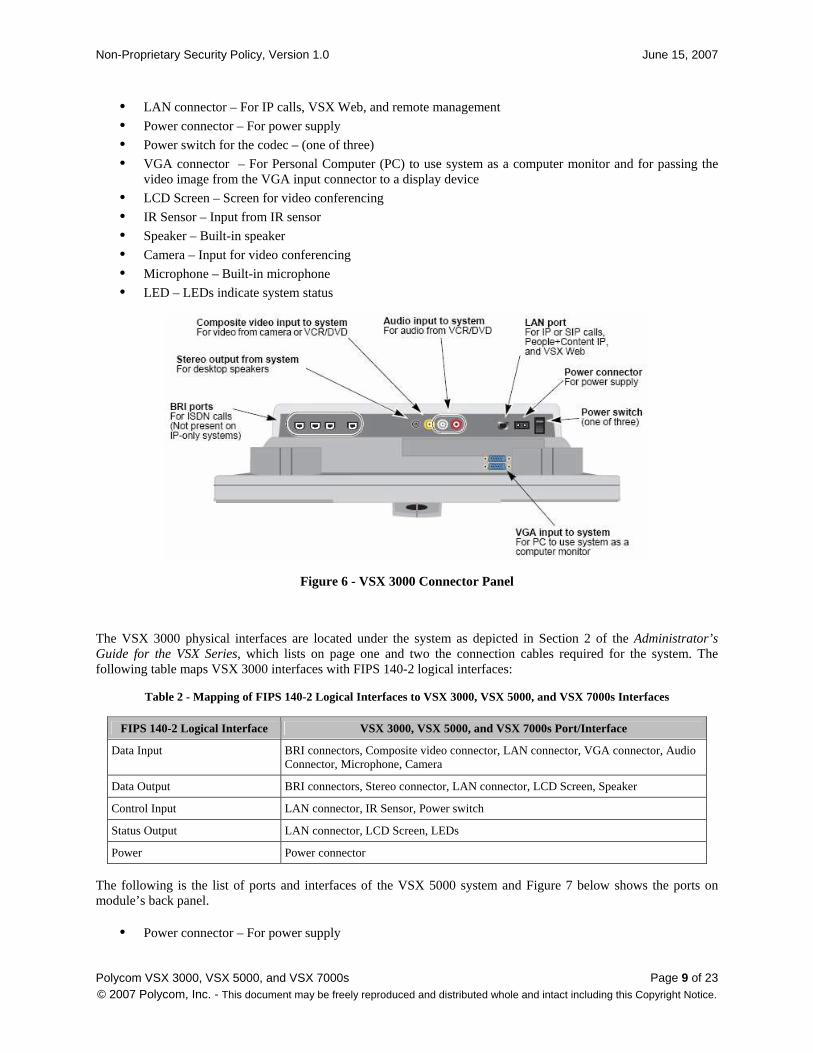
Ports and interfaces of the VSX 3000 system are shown in Figure 6 below. The ports on the module’s connector panel are listed below, and mapped to logical interfaces in Table 2 below.
• BRI connectors – For ISDN calls
• Stereo connector – For headphones or desktop speakers
• Composite video connector – Video input to the system from camera or VCR/DVD
• Audio connector – Audio input to the system from VCR/DVD
Non-Proprietary Security Policy, Version 1.0 June 15, 2007
Polycom VSX 3000, VSX 5000, and VSX 7000s Page 9 of 23 © 2007 Polycom, Inc. - This document may be freely reproduced and distributed whole and intact including this Copyright Notice.
• LAN connector – For IP calls, VSX Web, and remote management
• Power connector – For power supply
• Power switch for the codec – (one of three)
• VGA connector – For Personal Computer (PC) to use system as a computer monitor and for passing the video image from the VGA input connector to a display device
• LCD Screen – Screen for video conferencing
• IR Sensor – Input from IR sensor
• Speaker – Built-in speaker
• Camera – Input for video conferencing
• Microphone – Built-in microphone
• LED – LEDs indicate system status
Figure 6 - VSX 3000 Connector Panel
The VSX 3000 physical interfaces are located under the system as depicted in Section 2 of the Administrator’s Guide for the VSX Series, which lists on page one and two the connection cables required for the system. The following table maps VSX 3000 interfaces with FIPS 140-2 logical interfaces:
Table 2 - Mapping of FIPS 140-2 Logical Interfaces to VSX 3000, VSX 5000, and VSX 7000s Interfaces
FIPS 140-2 Logical Interface VSX 3000, VSX 5000, and VSX 7000s Port/Interface
Data Input BRI connectors, Composite video connector, LAN connector, VGA connector, Audio Connector, Microphone, Camera
Data Output BRI connectors, Stereo connector, LAN connector, LCD Screen, Speaker
Control Input LAN connector, IR Sensor, Power switch
Status Output LAN connector, LCD Screen, LEDs
Power Power connector
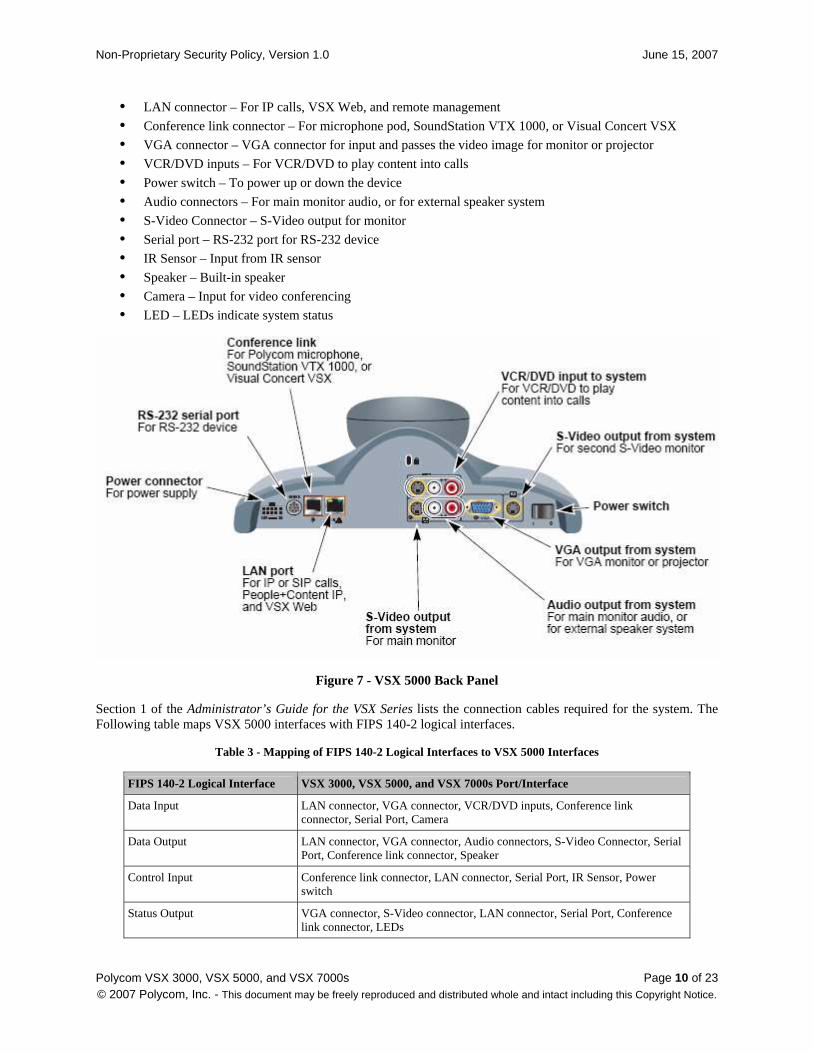
The following is the list of ports and interfaces of the VSX 5000 system and Figure 7 below shows the ports on module’s back panel.
• Power connector – For power supply
Non-Proprietary Security Policy, Version 1.0 June 15, 2007
Polycom VSX 3000, VSX 5000, and VSX 7000s Page 10 of 23 © 2007 Polycom, Inc. - This document may be freely reproduced and distributed whole and intact including this Copyright Notice.
• LAN connector – For IP calls, VSX Web, and remote management
• Conference link connector – For microphone pod, SoundStation VTX 1000, or Visual Concert VSX
• VGA connector – VGA connector for input and passes the video image for monitor or projector
• VCR/DVD inputs – For VCR/DVD to play content into calls
• Power switch – To power up or down the device
• Audio connectors – For main monitor audio, or for external speaker system
• S-Video Connector – S-Video output for monitor
• Serial port – RS-232 port for RS-232 device
• IR Sensor – Input from IR sensor
• Speaker – Built-in speaker
• Camera – Input for video conferencing
• LED – LEDs indicate system status
Figure 7 - VSX 5000 Back Panel
Section 1 of the Administrator’s Guide for the VSX Series lists the connection cables required for the system. The Following table maps VSX 5000 interfaces with FIPS 140-2 logical interfaces.
Table 3 - Mapping of FIPS 140-2 Logical Interfaces to VSX 5000 Interfaces
FIPS 140-2 Logical Interface VSX 3000, VSX 5000, and VSX 7000s Port/Interface
Data Input LAN connector, VGA connector, VCR/DVD inputs, Conference link connector, Serial Port, Camera
Data Output LAN connector, VGA connector, Audio connectors, S-Video Connector, Serial Port, Conference link connector, Speaker
Control Input Conference link connector, LAN connector, Serial Port, IR Sensor, Power switch
Status Output VGA connector, S-Video connector, LAN connector, Serial Port, Conference link connector, LEDs
Non-Proprietary Security Policy, Version 1.0 June 15, 2007
Polycom VSX 3000, VSX 5000, and VSX 7000s Page 11 of 23 © 2007 Polycom, Inc. - This document may be freely reproduced and distributed whole and intact including this Copyright Notice.
FIPS 140-2 Logical Interface VSX 3000, VSX 5000, and VSX 7000s Port/Interface
Power Power connector
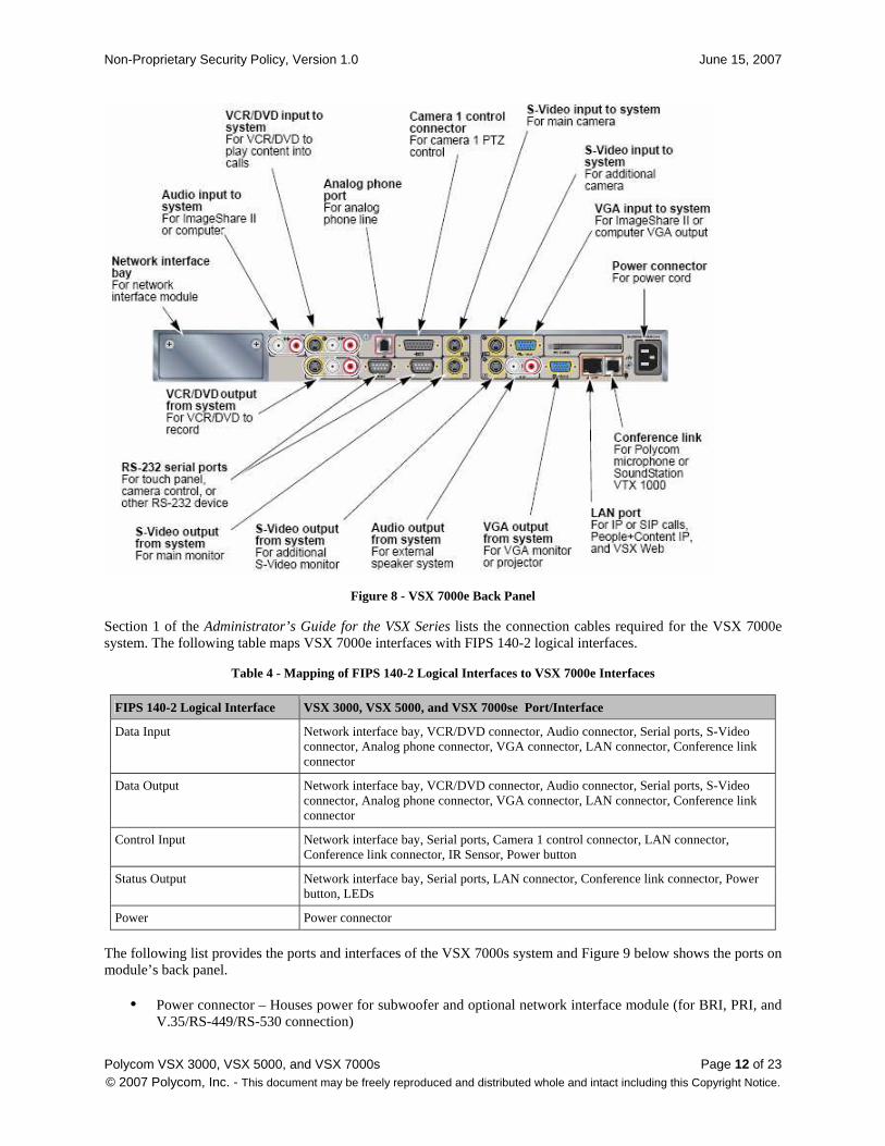
The following is the list of ports and interfaces for the VSX 7000e system and Figure 8 below shows the ports on module’s back panel.
• Network interface bay – For network interface module (for BRI, PRI, and V.35/RS-449/RS-530 connection)
• VCR/DVD connector – Play VCR/DVD content into calls or record the calls to VCR/DVD
• Audio connector – Input to system from ImageShare II and computer, or outputs to external speaker
• Serial ports – RS-232 port for touch panel, camera control, or other RS-232 devices
• S-Video connector – Input to system from camera or output for S-Video monitor
• Analog phone connector – For analog phone line
• Camera 1 control connector – For camera 1 PTZ control
• VGA connector – Input to system for ImageShare II and computer VGA, or outputs to VGA monitor and projector
• LAN connector – For IP calls, VSX Web, and remote management
• Conference link connector – For microphone pod, SoundStation VTX 1000, or Visual Concert VSX
• IR Sensor – Input from IR sensor
• Power button – Controls power and provides system status
• LED – LEDs indicate system status
• Power connector – For power cord
Non-Proprietary Security Policy, Version 1.0 June 15, 2007
Polycom VSX 3000, VSX 5000, and VSX 7000s Page 12 of 23 © 2007 Polycom, Inc. - This document may be freely reproduced and distributed whole and intact including this Copyright Notice.
Figure 8 - VSX 7000e Back Panel
Section 1 of the Administrator’s Guide for the VSX Series lists the connection cables required for the VSX 7000e system. The following table maps VSX 7000e interfaces with FIPS 140-2 logical interfaces.
Table 4 - Mapping of FIPS 140-2 Logical Interfaces to VSX 7000e Interfaces
FIPS 140-2 Logical Interface VSX 3000, VSX 5000, and VSX 7000se Port/Interface
Data Input Network interface bay, VCR/DVD connector, Audio connector, Serial ports, S-Video connector, Analog phone connector, VGA connector, LAN connector, Conference link connector
Data Output Network interface bay, VCR/DVD connector, Audio connector, Serial ports, S-Video connector, Analog phone connector, VGA connector, LAN connector, Conference link connector
Control Input Network interface bay, Serial ports, Camera 1 control connector, LAN connector, Conference link connector, IR Sensor, Power button
Status Output Network interface bay, Serial ports, LAN connector, Conference link connector, Power button, LEDs
Power Power connector
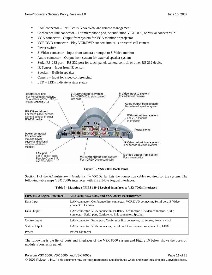
The following list provides the ports and interfaces of the VSX 7000s system and Figure 9 below shows the ports on module’s back panel.
• Power connector – Houses power for subwoofer and optional network interface module (for BRI, PRI, and V.35/RS-449/RS-530 connection)
Non-Proprietary Security Policy, Version 1.0 June 15, 2007
Polycom VSX 3000, VSX 5000, and VSX 7000s Page 13 of 23 © 2007 Polycom, Inc. - This document may be freely reproduced and distributed whole and intact including this Copyright Notice.
• LAN connector – For IP calls, VSX Web, and remote management
• Conference link connector – For microphone pod, SoundStation VTX 1000, or Visual concert VSX
• VGA connector – Output from system for VGA monitor or projector
• VCR/DVD connector – Play VCR/DVD connect into calls or record call content
• Power switch
• S-Video connector – Input from camera or output to S-Video monitor
• Audio connector – Output from system for external speaker system
• Serial RS-232 port – RS-232 port for touch panel, camera control, or other RS-232 device
• IR Sensor – Input from IR sensor
• Speaker – Built-in speaker
• Camera – Input for video conferencing
• LED – LEDs indicate system status
Figure 9 - VSX 7000s Back Panel
Section 1 of the Administrator’s Guide for the VSX Series lists the connection cables required for the system. The following table maps VSX 7000s interfaces with FIPS 140-2 logical interfaces.
Table 5 - Mapping of FIPS 140-2 Logical Interfaces to VSX 7000s Interfaces
FIPS 140-2 Logical Interface VSX 3000, VSX 5000, and VSX 7000ss Port/Interface
Data Input LAN connector, Conference link connector, VCR/DVD connector, Serial port, S-Video connector, Camera
Data Output LAN connector, VGA connector, VCR/DVD connector, S-Video connector, Audio connector, Serial port, Conference link connector, Speaker
Control Input LAN connector, Serial port, Conference link connector, IR Sensor, Power switch
Status Output LAN connector, VGA connector, Serial port, Conference link connector, LEDs
Power Power connector
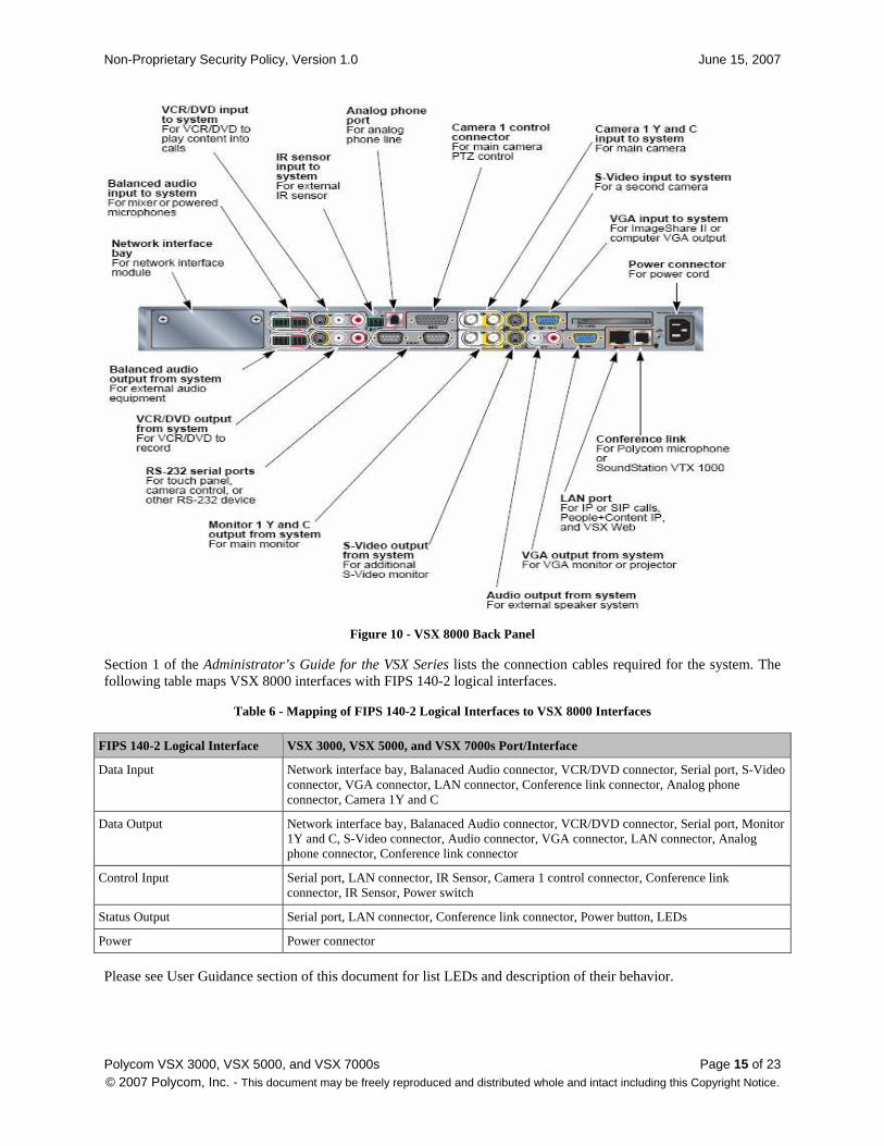
The following is the list of ports and interfaces of the VSX 8000 system and Figure 10 below shows the ports on module’s connector panel.
Non-Proprietary Security Policy, Version 1.0 June 15, 2007
Polycom VSX 3000, VSX 5000, and VSX 7000s Page 14 of 23 © 2007 Polycom, Inc. - This document may be freely reproduced and distributed whole and intact including this Copyright Notice.
• Network interface bay – For network interface module (for BRI, PRI, and V.35/RS-449/RS-530 connection)
• Balanced Audio connector – Input for mixed or powerful microphones or output for external audio equipment
• VCR/DVD connector – Play VCR/DVD content into calls or record the calls to VCR/DVD
• Serial ports – RS-232 port for touch panel, camera control, or other RS-232 device
• Monitor 1Y and C – output for main monitor
• S-Video connector – Input to system from camera or output for S-Video monitor
• Audio connector –Output to external speaker
• VGA connector – Input to system for ImageShare II and computer VGA, or outputs to VGA monitor and projector
• LAN connector – For IP calls, VSX Web, and remote management
• Conference link connector – For microphone pod, SoundStation VTX 1000, or Visual Concert VSX
• IR Sensor – Input from external IR sensor
• Analog phone connector – For analog phone line
• Camera 1 control connector – For camera 1 PTZ control
• Camera 1Y and C – Input from main camera
• IR Sensor – Input from IR sensor
• Power button – Controls power and provides system status
• LED – LEDs indicate system status
• Power connector – For power cord
Non-Proprietary Security Policy, Version 1.0 June 15, 2007
Polycom VSX 3000, VSX 5000, and VSX 7000s Page 15 of 23 © 2007 Polycom, Inc. - This document may be freely reproduced and distributed whole and intact including this Copyright Notice.
Figure 10 - VSX 8000 Back Panel
Section 1 of the Administrator’s Guide for the VSX Series lists the connection cables required for the system. The following table maps VSX 8000 interfaces with FIPS 140-2 logical interfaces.
Table 6 - Mapping of FIPS 140-2 Logical Interfaces to VSX 8000 Interfaces
FIPS 140-2 Logical Interface VSX 3000, VSX 5000, and VSX 7000s Port/Interface
Data Input Network interface bay, Balanaced Audio connector, VCR/DVD connector, Serial port, S-Video connector, VGA connector, LAN connector, Conference link connector, Analog phone connector, Camera 1Y and C
Data Output Network interface bay, Balanaced Audio connector, VCR/DVD connector, Serial port, Monitor 1Y and C, S-Video connector, Audio connector, VGA connector, LAN connector, Analog phone connector, Conference link connector
Control Input Serial port, LAN connector, IR Sensor, Camera 1 control connector, Conference link connector, IR Sensor, Power switch
Status Output Serial port, LAN connector, Conference link connector, Power button, LEDs
Power Power connector
Please see User Guidance section of this document for list LEDs and description of their behavior.
Non-Proprietary Security Policy, Version 1.0 June 15, 2007
Polycom VSX 3000, VSX 5000, and VSX 7000s Page 16 of 23 © 2007 Polycom, Inc. - This document may be freely reproduced and distributed whole and intact including this Copyright Notice.
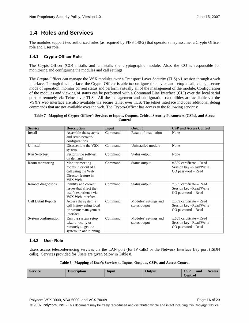
1.4 Roles and Services
The modules support two authorized roles (as required by FIPS 140-2) that operators may assume: a Crypto Officer role and User role.
1.4.1 Crypto-Officer Role
The Crypto-Officer (CO) installs and uninstalls the cryptographic module. Also, the CO is responsible for monitoring and configuring the modules and call settings.
The Crypto-Officer can manage the VSX modules over a Transport Layer Security (TLS) v1 session through a web interface. Through this interface, the Crypto-Officer is able to configure the device and setup a call, change secure mode of operation, monitor current status and perform virtually all of the management of the module. Configuration of the modules and viewing of status can be performed with a Command Line Interface (CLI) over the local serial port or remotely via Telnet over TLS. All the management and configuration capabilities are available via the VSX’s web interface are also available via secure telnet over TLS. The telnet interface includes additional debug commands that are not available over the web. The Crypto-Officer has access to the following services:
Table 7 - Mapping of Crypto-Officer’s Services to Inputs, Outputs, Critical Security Parameters (CSPs), and Access Control
Service Description Input Output CSP and Access Control Install Assemble the systems
and setup network configurations
Command Result of installation None
Uninstall Disassemble the VSX system
Command Uninstalled module None
Run Self-Test Perform the self-test on demand
Command Status output None
Room monitoring Monitor meeting rooms in or out of a call using the Web Director feature in VSX Web.
Command Status output x.509 certificate – Read Session key –Read/Write CO password – Read
Remote diagnostics Identify and correct issues that affect the user’s experience via VSX Web interface.
Command Status output x.509 certificate – Read Session key –Read/Write CO password – Read
Call Detail Reports Access the system’s call history using local or remote management interface.
Command Modules’ settings and status output
x.509 certificate – Read Session key –Read/Write CO password – Read
System configuration Run the system setup wizard locally or remotely to get the system up and running.
Command Modules’ settings and status output
x.509 certificate – Read Session key –Read/Write CO password – Read
1.4.2 User Role
Users access teleconferencing services via the LAN port (for IP calls) or the Network Interface Bay port (ISDN calls). Services provided for Users are given below in Table 8.
Table 8 - Mapping of User’s Services to Inputs, Outputs, CSPs, and Access Control
Service Description Input Output CSP and Access Control
Non-Proprietary Security Policy, Version 1.0 June 15, 2007
Polycom VSX 3000, VSX 5000, and VSX 7000s Page 17 of 23 © 2007 Polycom, Inc. - This document may be freely reproduced and distributed whole and intact including this Copyright Notice.
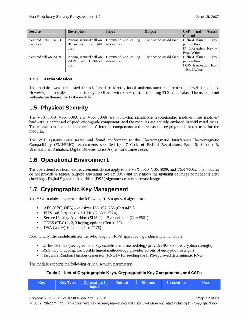
Service Description Input Output CSP and Access Control
Secured call on IP network
Placing secured call on IP network via LAN port
Command and calling information
Connection established Diffie-Hellman key pairs – Read IP Encryption Key – Read/Write
Secured call on ISDN Placing secured call on ISDN via BRI/PRI port
Command and calling information
Connection established Diffie-Hellman key pairs – Read ISDN Encryption Key – Read/Write
1.4.3 Authentication
The modules were not tested for role-based or identity-based authentication requirement as level 1 modules. However, the modules authenticate Crypto-Officer with x.509 certificate during TLS handshake. The users do not authenticate themselves to the module.
1.5 Physical Security
The VSX 3000, VSX 5000, and VSX 7000s are multi-chip standalone cryptographic modules. The modules’ hardware is composed of production-grade components and the modules are entirely enclosed in solid metal cases. These cases enclose all of the modules’ internal components and serve as the cryptographic boundaries for the modules.
The VSX systems were tested and found conformant to the Electromagnetic Interference/Electromagnetic Compatibility (EMI/EMC) requirements specified by 47 Code of Federal Regulations, Part 15, Subpart B, Unintentional Radiators, Digital Devices, Class A (i.e., for business use).
1.6 Operational Environment
The operational environment requirements do not apply to the VSX 3000, VSX 5000, and VSX 7000s. The modules do not provide a general purpose Operating System (OS) and only allow the updating of image components after checking a Digital Signature Algorithm (DSA) signature on new software images.
1.7 Cryptographic Key Management
The VSX modules implement the following FIPS-approved algorithms:
• AES (CBC, OFB) - key sizes 128, 192, 256 (Cert #431) • FIPS 186-2 Appendix 3.1 PRNG (Cert #224) • Secure Hashing Algorithm (SHA-1) – Byte oriented (Cert #501) • TDES (CBC) 1, 2, 3 keying options (Cert #460) • DSA (verify) 1024 bits (Cert #178)
Additionally, the module utilizes the following non-FIPS-approved algorithm implementation:
• Diffie-Hellman (key agreement, key establishment methodology provides 80-bits of encryption strength) • RSA (key wrapping, key establishment methodology provides 80-bits of encryption strength) • Hardware Random Number Generator (RNG) – for seeding the FIPS-approved deterministic RNG
The module supports the following critical security parameters:
Table 9 - List of Cryptographic Keys, Cryptographic Key Components, and CSPs
Key Key Type Generation / Input
Output Storage Zeroization Use

Non-Proprietary Security Policy, Version 1.0 June 15, 2007
Polycom VSX 3000, VSX 5000, and VSX 7000s Page 18 of 23 © 2007 Polycom, Inc. - This document may be freely reproduced and distributed whole and intact including this Copyright Notice.
Key Key Type Generation / Input
Output Storage Zeroization Use
x.509 certificate (RSA Public key)
1024 bits RSA public key
Generated externally, input in plaintext
Output in plaintext
Stored in Flash in plaintext
Erasing the flash image
Authenticates the module during TLS handshake
RSA Private key 1024 bits RSA private key
Generated externally, input in plaintext
Never exits the module
Stored in Flash in plaintext
Erasing the flash image
Authenticates the module during TLS handshake
Diffie-Hellman public key
1024 bits public key
Generated internally
Output in plaintext
Stored in volatile memory
Zerorized on reboot.
Establishes a session key (IP or ISDN Encryption Key) during H.323 negotiation
Diffie-Hellman private key
1024 bits private key
Generated internally
Never exits the module
Stored in volatile memory
Zerorized on reboot.
Establishes a session key (IP or ISDN Encryption Key) during H.323 negotiation
Integrity Check Key
1024 bits DSA Public key
Generated externally, inputted in plaintext
Never exits the module
Stored in Flash in plaintext
Erasing the flash image
Checks integrity of the software at power-up of the module
Session Key 192 bits TDES CBC key
Generated internally during TLS handshake
Exits in encrypted form (RSA key transport)
Held in volatile memory in plaintext.
Zerorized on reboot.
Encrypts TLS traffic
IP Encryption Key
128 bits AES CBC key
Generated internally during Diffie-Hellman key agreement
Never exits the module
Held in volatile memory in plaintext.
Zerorized on reboot.
Encrypts IP calls
ISDN Encryption Key
128, 192, 256 bits AES OFB keys
Generated internally during Diffie-Hellman key agreement
Never exits the module
Held in volatile memory in plaintext.
Zerorized on reboot.
Encrypts ISDN calls
PRNG seed 20 bytes of seed value
Internally generated
Never exits the module
Held in volatile memory only in plaintext.
Zerorized on reboot
Produce FIPS approved random number
1.7.1 Key Generation
The modules generate symmetric keys and FIPS-approved PRNG seeds internally. The symmetric keys (Session Key, IP Encryption Key, and ISDN Encryption Key) and Diffie-Hellman key pair are generated using a FIPS-approved 186-2 Appendix 3.1 algorithm. Twenty bytes of hardware generated noise is used to create a PRNG seed, and RSA key pair is generated externally and input into the module in plaintext.
1.7.2 Key Input/Output
Rivest, Shamir, Adleman (RSA) key pair is generated externally and input to the modules in plaintext. The RSA private key and DH private key never exit the module, while the public keys are output in plaintext. The Session key exits the module in encrypted form during TLS handshakes (protected within RSA key transport). The IP Encryption Key and ISDN Encryption Key are never output from the module. Other CSPs and keys, such as the Integrity Check Key and PRNG seed are never output from the modules.
Non-Proprietary Security Policy, Version 1.0 June 15, 2007
Polycom VSX 3000, VSX 5000, and VSX 7000s Page 19 of 23 © 2007 Polycom, Inc. - This document may be freely reproduced and distributed whole and intact including this Copyright Notice.
1.7.3 Key Storage
The RSA public/private key pair and Integrity Check Key are stored in the modules’ flash drives in plaintext form. The Session Key, IP Encryption Key, ISDN Encryption Key, DH public/private key pair, and PRNG seed are held in volatile memory in plaintext.
1.7.4 Key Zeroization
The RSA key pair is zeroized by overwriting the flash image. The Session Key, IP Encryption Key, ISDN Encryption Key, Diffie-Hellman (DH) private/public key pair and PRNG seed are available only temporarily in volatile memory during video calls. These ephemeral keys and CSP are zeroized after the session is closed or whenever power is cycled.
1.8 Self-Tests
The VSX 3000, VSX 5000, and VSX 7000s perform the following self-tests at power-up:
• Software integrity check using a DSA signature verification • Known Answer Tests (KATs)
o AES Known Answer Test (KAT) o Triple-DES KAT o RSA pairwise consistency check o FIPS 186-2 Appendix 3.1 PRNG KAT
The cryptographic modules also perform the following conditional self-tests:
• Continuous RNG for FIPS 186-2 PRNG • Continuous RNG for non-approved RNG for entropy gathering
If any of the power-up self-test fails, the modules log the failure, and notification is provided to Crypto Officers through serial traces. Security relevant module functionality is not provided until all self-tests are passed. In case a self-test fails, the logged trace indicates which self-test failed, and the modules display a warning message indicating the required reboot for the system. Since these messages are not available through the Secure Telnet interface before all self-tests have passed, the messages are echoed to any connected monitor screen.
1.9 Design Assurance
Polycom uses automated Configuration Management (CM) of their source code modules, organizing source code into separate version-controlled depots. Polycom uses Accurev’s TimeSafe® Configuration Management System to perform automated source code control. Additionally, Microsoft Visual Source Safe (VSS) version 6.0 is used to provide configuration management for the module’s FIPS documentation. This CM software and Polycom’s process provides access control, versioning, and logging for all module source code and documentation.
Non-Proprietary Security Policy, Version 1.0 June 15, 2007
Polycom VSX 3000, VSX 5000, and VSX 7000s Page 20 of 23 © 2007 Polycom, Inc. - This document may be freely reproduced and distributed whole and intact including this Copyright Notice.
2 Secure Operation The VSX 3000, VSX 5000, and VSX 7000s meet Level 1 requirements for FIPS 140-2. The sections below describe how to place and keep the module in FIPS-approved mode of operation.
2.1 Crypto-Officer Guidance
The Crypto-Officer is responsible for initialization and security-relevant configuration and management of the module through the web management interface, serial port from a non networked PC, or secure Telnet over TLS. Please see Polycom’s Administrator’s Guide for the VSX Series for more information on setting up, configuring and maintaining the modules.
2.1.1 Initialization
The Crypto-Officer is responsible for putting the modules in FIPS mode of Operation, by enabling the system to automatically encrypt calls. AES encryption is a standard feature on all VSX systems. The system will be shipped by default in Non-Secure Mode. To put the modules in FIPS mode of Operation, the Crypto-Officer must:
o Go to System →→→→ Admin Settings →→→→ System Security
o Select Secure Mode
o Selecting the Secure mode will result in a system reset
o The change of mode from Non-Secure mode to secure mode shall initiate Crypto-Officer password change request
2.1.2 Management
Following are the points of System behavior in FIPS mode of Operation:
o Default password (System Serial number) or Dummy password (No password), is not allowed for 'admin' login in the secured mode.
o Only https over TLS, secure telnet, and secure FTP connections are allowed in the secured mode. The standard http connections with no security will not be allowed.
o Media encryption during a call (H.323/H.320) will always be set to ON (AES-Encryption ON)
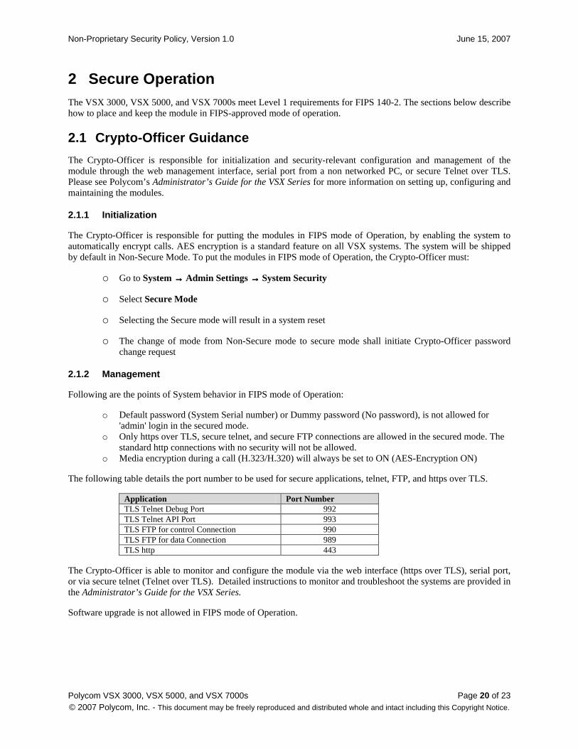
The following table details the port number to be used for secure applications, telnet, FTP, and https over TLS.
Application Port Number TLS Telnet Debug Port 992 TLS Telnet API Port 993 TLS FTP for control Connection 990 TLS FTP for data Connection 989 TLS http 443
The Crypto-Officer is able to monitor and configure the module via the web interface (https over TLS), serial port, or via secure telnet (Telnet over TLS). Detailed instructions to monitor and troubleshoot the systems are provided in the Administrator’s Guide for the VSX Series.
Software upgrade is not allowed in FIPS mode of Operation.
Non-Proprietary Security Policy, Version 1.0 June 15, 2007
Polycom VSX 3000, VSX 5000, and VSX 7000s Page 21 of 23 © 2007 Polycom, Inc. - This document may be freely reproduced and distributed whole and intact including this Copyright Notice.
2.2 User Guidance
The User does not have the ability to configure sensitive information on the module. They only access the secured communication functionality of the module. Users can find the basic instructions to use the VSX systems in Getting Started Guide for the VSX Series.
Users are responsible for determining when to place encrypted video calls, determining when they wish to verify encryption keys with the other side on a video call, and whether they wish to hang up a video call if encryption cannot be setup or keys verified. Users may not place unencrypted calls in FIPS mode of operation.
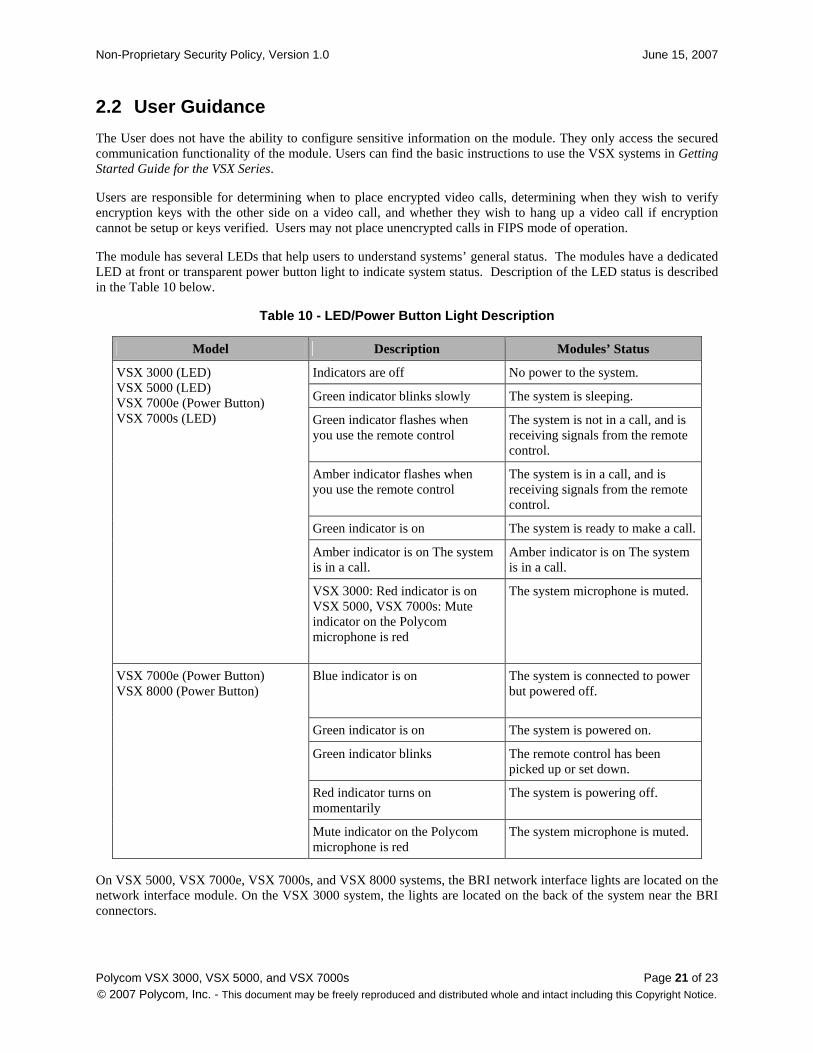
The module has several LEDs that help users to understand systems’ general status. The modules have a dedicated LED at front or transparent power button light to indicate system status. Description of the LED status is described in the Table 10 below.
Table 10 - LED/Power Button Light Description
Model Description Modules’ Status
Indicators are off No power to the system.
Green indicator blinks slowly The system is sleeping.
Green indicator flashes when you use the remote control
The system is not in a call, and is receiving signals from the remote control.
Amber indicator flashes when you use the remote control
The system is in a call, and is receiving signals from the remote control.
Green indicator is on The system is ready to make a call.
Amber indicator is on The system is in a call.
Amber indicator is on The system is in a call.
VSX 3000 (LED) VSX 5000 (LED) VSX 7000e (Power Button) VSX 7000s (LED)
VSX 3000: Red indicator is on VSX 5000, VSX 7000s: Mute indicator on the Polycom microphone is red
The system microphone is muted.
Blue indicator is on The system is connected to power but powered off.
Green indicator is on The system is powered on.
Green indicator blinks The remote control has been picked up or set down.
Red indicator turns on momentarily
The system is powering off.
VSX 7000e (Power Button) VSX 8000 (Power Button)
Mute indicator on the Polycom microphone is red
The system microphone is muted.
On VSX 5000, VSX 7000e, VSX 7000s, and VSX 8000 systems, the BRI network interface lights are located on the network interface module. On the VSX 3000 system, the lights are located on the back of the system near the BRI connectors.
Non-Proprietary Security Policy, Version 1.0 June 15, 2007
Polycom VSX 3000, VSX 5000, and VSX 7000s Page 22 of 23 © 2007 Polycom, Inc. - This document may be freely reproduced and distributed whole and intact including this Copyright Notice.
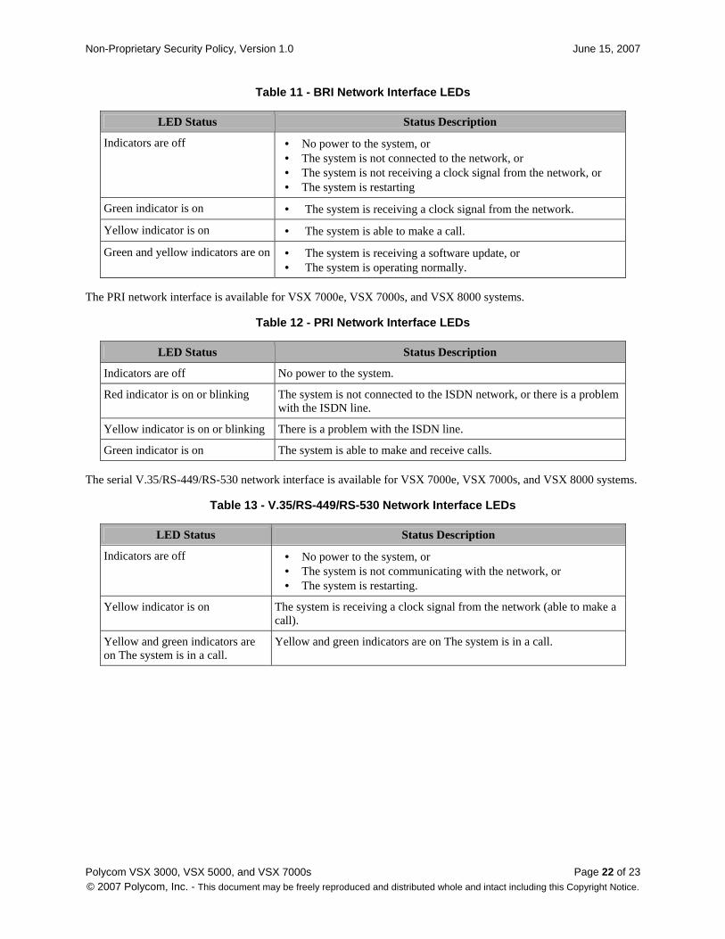
Table 11 - BRI Network Interface LEDs
LED Status Status Description
Indicators are off • No power to the system, or • The system is not connected to the network, or • The system is not receiving a clock signal from the network, or • The system is restarting
Green indicator is on • The system is receiving a clock signal from the network.
Yellow indicator is on • The system is able to make a call.
Green and yellow indicators are on • The system is receiving a software update, or • The system is operating normally.
The PRI network interface is available for VSX 7000e, VSX 7000s, and VSX 8000 systems.
Table 12 - PRI Network Interface LEDs
LED Status Status Description
Indicators are off No power to the system.
Red indicator is on or blinking The system is not connected to the ISDN network, or there is a problem with the ISDN line.
Yellow indicator is on or blinking There is a problem with the ISDN line.
Green indicator is on The system is able to make and receive calls.
The serial V.35/RS-449/RS-530 network interface is available for VSX 7000e, VSX 7000s, and VSX 8000 systems.
Table 13 - V.35/RS-449/RS-530 Network Interface LEDs
LED Status Status Description
Indicators are off • No power to the system, or • The system is not communicating with the network, or • The system is restarting.
Yellow indicator is on The system is receiving a clock signal from the network (able to make a call).
Yellow and green indicators are on The system is in a call.
Yellow and green indicators are on The system is in a call.
Non-Proprietary Security Policy, Version 1.0 June 15, 2007
Polycom VSX 3000, VSX 5000, and VSX 7000s Page 23 of 23 © 2007 Polycom, Inc. - This document may be freely reproduced and distributed whole and intact including this Copyright Notice.
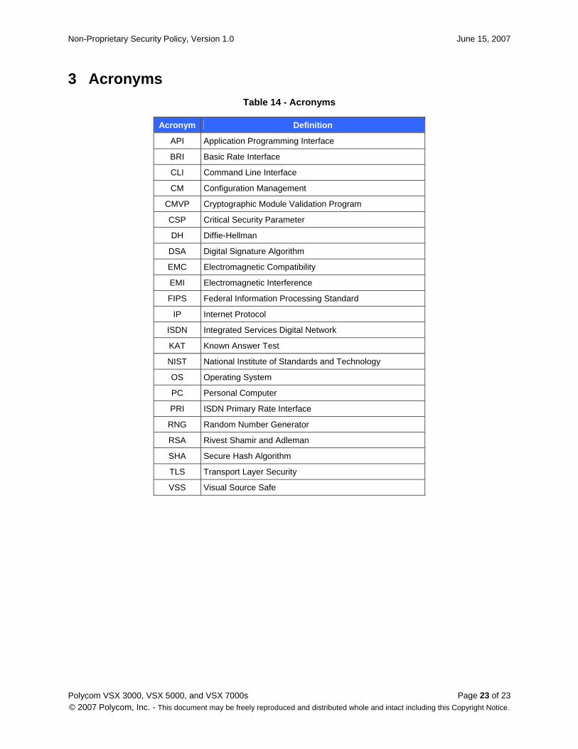
3 Acronyms Table 14 - Acronyms
Acronym Definition
API Application Programming Interface
BRI Basic Rate Interface
CLI Command Line Interface
CM Configuration Management
CMVP Cryptographic Module Validation Program
CSP Critical Security Parameter
DH Diffie-Hellman
DSA Digital Signature Algorithm
EMC Electromagnetic Compatibility
EMI Electromagnetic Interference
FIPS Federal Information Processing Standard
IP Internet Protocol
ISDN Integrated Services Digital Network
KAT Known Answer Test
NIST National Institute of Standards and Technology
OS Operating System
PC Personal Computer
PRI ISDN Primary Rate Interface
RNG Random Number Generator
RSA Rivest Shamir and Adleman
SHA Secure Hash Algorithm
TLS Transport Layer Security
VSS Visual Source Safe