vsystem reverse 3 3 small - · pdf filereplace with m5 or m6 spigot (part 5 or part 6) as...
TRANSCRIPT
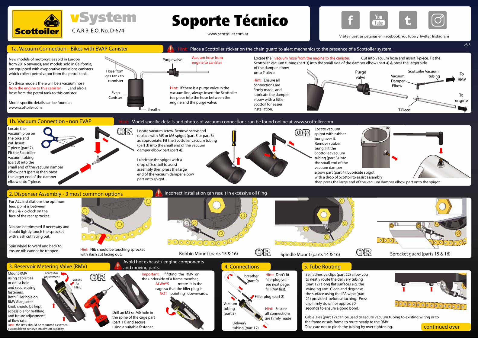
Locate the vacuum pipe onthe bike and cut. Insert T-piece (part 7). Fit the Scottoiler vacuum tubing (part 3) into the small end of the vacuum damper elbow part (part 4) then press the larger end of the damper elbow onto T-piece.
Locate vacuum screw. Remove screw and replace with M5 or M6 spigot (part 5 or part 6) as appropriate. Fit the Scottoiler vacuum tubing (part 3) into the small end of the vacuum damper elbow part (part 4).
Lubricate the spigot with a drop of Scottoil to assist assembly then press the large end of the vacuum damper elbow part onto spigot.
OR OR1b. Vacuum Connection - non EVAP Hint: w.scottoiler.com
Locate vacuum spigot with rubber bung over it. Remove rubber bung. Fit the Scottoiler vacuum tubing (part 3) into the small end of the vacuum damper elbow part (part 4). Lubricate spigot with a drop of Scottoil to assist assembly then press the large end of the vacuum damper elbow part onto the spigot.
2. Dispenser Assembly - 3 most common options
Bobbin Mount (parts 15 & 16) Spindle Mount (parts 14 & 16) Sprocket guard (parts 15 & 16)
For ALL installations the optimum feed point is between the 5 & 7 o'clock on the face of the rear sprocket.
Nib can be trimmed if necessary and should lightly touch the sprocketwith slash cut facing out.
Spin wheel forward and back to ensure nib cannot be trapped.
Incorrect installation can r
OR OR
Drill an M5 or M6 hole in the spine of the cage part (part 11) and secure using a suitable fastener.
Mount RMV using cable tiesor drill a hole and secure using fasteners.Both Filler hole on RMV & adjuster knob should be kept accessible for rand future adjustment
access for
access for adjustment
3. Reservoir Metering Valve (RMV)
OR Important:the underside of a frame member, ALWAYS rotate it in the
NOT pointing downwards.
Hint: Nib should be touching sprocket with slash cut facing out.
Hint: the RMV should be mounted as vertical as possible to achieve maximum capacity.
Cable Ties (part 12) can be used to secure vacuum tubing to existing wiring or to the frame or sub-frame to route neatly to the RMV. Take care not to pinch the tubing by over tightening.
Self adhesive clips (part 22) allow you to neatly route the delivery tubing
swinging arm. Clean and degrease the surface using the IPA wipe (part 21) provided before attaching. Press
rox 30 seconds to ensure a good bond.
5. Tube Routing
continued over
Hint: Ensure all connectionsar
Delivery tubing (part 12)
Vacuumtubing(part 3)
Filler plug (part 2)
breather(part 9)
4. ConnectionsAvoid hot exhaust / engine components and moving parts.
Hint: Don’
see next page,
T-Piece
VacuumDamperElbow
To RMV
To engine
Purgevalve
Hint: Ensure all connections are
lubricate the damper elbow with a littleScottoil for easier installation.
Hint: If there is a purge valve in thevacuum line, always insert the Scottoilertee piece into the hose between the engine and the purge valve.
Locate the vacuum hose from the engine to the canister. Cut into vacuum hose and insert T-piece. Fit the Scottoiler vacuum tubing (part 3) into the small side of the damper elbow (part 4) & press the larger side of the damper elbow onto T-piece.
New models of motorcycles sold in Europefrom 2016 onwards, and models sold in California,are equipped with evaporative emissions canisterswhich collect petrol vapor from the petrol tank.
On these models there will be a vacuum hosefrom the engine to this canister , and also ahose from the petrol tank to this canister.
www.scottoiler.com
EvapCanister
Breather
Purge valve
Hose from gas tank to
cannister
Vacuum hose fromengine to canister.
1a. Vacuum Connection - Bikes with EVAP Canister
Scottoiler Vacuumtubing
Hint: Place a Scottoiler sticker on the chain guard to alert mechanics to the presence of a Scottoiler system.
C.A.R.B. E.O. No. D-674
v3.3
www.scottoiler.com.ar
Soporte TécnicoVisite nuestras páginas en Facebook, YouTube y Twitter, Instagram
®

1. Which products are suitable for my bike? Visit our website www.scottoiler.com.ar and select your bike ‘Manufacturer’ and ‘Model’. Select the kit you want and download the installation guide PDF. Occasionally an adapter will be required. This will be detailed on the installation PDF.
2. What oil should I use to re�ll my Scottoiler? In ambient temperatures between 0 and 30 degrees Celcius (32 and 86 degrees Farenheit) we recommend Scottoil Tradi -tional - Blue and in ambient temperature between 20 and 40 degrees Celcius (68 and 104 degrees Farenheit) we recommend Scottoil High Temperature - Red. Scottoil features a very low tack additive thus not attracting dirt. Scottoiler cannot guarantee the compatibility of our systems using any other manufacturers oils as the materials used are tested for compatibilty with Scottoil only..
3. When should I re�ll my RMV (Reservoir Metering Valve)? If you re�ll the oiler before it runs dry you won’t have to prime the dispenser tube. The Reservoir Metering Valve takes around ten seconds to top up with 50ml of oil which should last up to 1,500 miles..
4. Can I increase the capacity? Yes, the Magnum High Capacity Reservoir increases capacity by up to eight times. The HCR is �tted behind the number plate and the combined increased capacity will give up to 10,000 additional miles between re�lls.Alternatively, the Lube Tube �exible high capacity reservoir increases combined capac -ity by up to four times. The Lube Tube can be �tted into any dead space on the bike and will mean up to 6,000 additional miles between re�lls. .
5. Will the Scottoiler only oil one side of my chain? No. The oil is fed to the chain via the sprocket face where it splits over the inner side plates. Some of the oil is diverted onto the o-rings and the remainder feeds under the roller onto the bushing. Capillary action will then draw the oil across the chain. For best results load the chain with oil from the bottle or a rag after cleaning and then apply approx 1 drop per minute to maintain this �lm of oil..
6. Will I get oil on my tyre? No, A �ow rate of approximately one drop per minute applied via the sprocket face will provide an oil-�lm which will not pollute the running surface of the tyre and will give a dramatic improvement in chain life. In conditions where high levels of dust, sand or heavy rain are present more oil �ow will be neces -sary to extend chain life..
7. When do I need to adjust �ow? Temperature change will alter the �ow rate of the oiler. The oil will �ow more quickly in warm temperatures as it will get thinner. The oil will �ow more slowly in cold temperatures as it will get thicker. It is important to monitor the �ow rate with temperature change and adjust �ow accordingly. .
8. I want to move my Scottoiler onto my new bike, are the spare parts avail -able separately? Yes, the full range of spare parts, �ttings and accessories are available online at www.scottoiler.com .. .
9. Does this system satisfy the requirements of the Californian Air Resource Board? Yes. Scottoiler have submitted the vSystem kit to the Californian Air Resource Board and have received an Exemption Order (E.O.). The E.O. number is printed on the enclosed sticker (Part 24). This sticker should be �xed to the bike near the reservoir (RMV) or actually onto the reservoir (RMV) itself to comply with the CARB requirements for this product.
How It Works Frequently Asked Questions (FAQ)
Engine Sucks Valve Open
To engine vacuum
Vacuum damper assembly
Only 3ccs of air moves back and forwards so no engine interference
Flow adjuster knob
Reservoir Metering Valve (RMV)
Rotating �lter �nds oil when RMV is horizontal
Breather
Filler plug
Closing spring
Connector for
priming & HCR
reservoir or
Lube Tube
Valve
Centrifugal force injects oil into chain
How does the Scottoiler work? The Scottoiler vSystem is vacuum operated. When the motorcycle engine is running vacuum is generated, this lifts a diaphragm which in turn opens the valve. Whilst open the valve allows oil to drip feed under gravity down the delivery tube to the chain via the rear sprocket. There is metering built into the valve to provide adjustment to control the rate at which oil is dispensed. It is not a pump..
How does this a�ect the engine? It doesn’t. The Scottoiler’s output is not a�ected by engine speed, throttle opening and so on. The vacuum chamber is a sealed unit and does not a�ect the running of the bike. Upon starting the engine the valve will open, this requires 3cc of air to be moved in order to lift the diaphragm, which stays up until the engine is switched o�. It is not unusual to see the diaphragm pulsating with very low revs, particularly on singles and twins, don’t confuse this for a pumping action, it is not a pump.
.....................
Head of oil pressure
More height gives more �ow.
Oil is dispensed into chain via sprocket face
Capillary oil route to other side of chain
Limited WarrantyAll Scottoiler products are guaranteed to be free from defects in materials and
workmanship for a period of two years from date of purchase. Please register your product online at www.scottoiler.com/guarantee to verify the date of purchase.Important: Do not tamper with, modify or dismantle any part of your Scottoiler system. Such actions could damage the product and may invalidate the product
warranty.
Parts List
34
5 67b
7a
8
9
10
11
12
13
14
2019
Parts List
www.sco tt oiler.comCARB E.O. No. D-674
2 Riverside, Glasgow G62 6PL, UK
Model : vSystem
IsopropanolCleaning
Tissue
21
Sco tt oiler ®
Scottoiler ®
Scottoiler ®
14. Dispenser Plate (RM-150060)
15. Dispenser Plate Clip (RM-150065)
16. Small Dispenser Plate (RM-150062)
17. IPA Wipe (RM-100125)
18. Adhesive Clips (x4) (SA-0175)19. 250ml Scottoil (SA-0008)20. Filling / Priming Spout (SA-0126)21. Scottoiler Stickers (assorted)22. M8 Screw (x1) (RM-150143)
23. M6 Screw (x1) (RM-160050)
24. CARB EO Sticker (RM-150217)
1. RMV (Reservoir Metering Valve) (SO-0028) 2. Filler Plug (SA-0040) 3. Vacuum Tubing (Black) (SC-0051) 4. Vacuum Damper Elbow (SA-0100) 5. M5 Spigot (RM-150125)
6. M6 Spigot (RM-150135)
7a. T-Piece 4mm (RM-150005)
7b. T-Piece 6mm (RM-150250)
8. Instructions (SA-0084) 9. Breather Assembly (SA-0010) 10. Spare Nib (x2) (SA-0075) 11. RMV Cage (SA-0600) 12. Cable Ties (x6) (SA-0015) 13. Dispenser Assembly (SA-0024)
16
15
17
18
24
23
22
1
2
6. RMV FillingRemove the black rubber �llerplugpart (part 2) from the side of the RMV.
Fit the spout to the bottle of Scottoiland �ll the RMV though the holein the side of the reservoir.
Important: Do not tamper with, modify or dismantle any part of your Scottoiler system. Such actions could damage the product, and/or you r motorcycle, and may invalidate the product warranty.
7. Prime SystemPress Filler plug (part 2) into the RMV and turn the adjuster at the top of the RMV fully clockwise to “Prime”position.
Never attempt to use compressed airto �ll or prime your system.
Connect the spout to the Filler Plug.Squeeze the bottle of oil to pressurise the system. This will force oil down the delivery tubing. Squeeze until there are no bubbles.
Hint: Holdbottle
upright
8. Set Flow Rate
60 secs
Hint: 1 drop per minute providesthe optimal �ow rate
For best results, clean the chain thoroughly with para�n and a nylon brush. Manually drizzle Scottoil along the length of the chain and wipe o� any excess. The �ow from the RMV then simply tops up this initial coating.
Top Tech Tip:
Re�t the �ller plug and breather. Route the breather up and over, with the end pointing downwards to prevent water ingress. Start your bike. Adjust the �ow until approx. 1drop per minute is achieved. Check �ow after a short journey, &adjust if necessary.
Hint: Occasionally an adapter is required. This will be detailed online on the model speci�c guide at www.scottoiler.com