vw comm module - canary · pdf filesection 1 - introduction 3 1.1 overview the vw comm module...
TRANSCRIPT

VW Comm Module
USER’S GUIDE
Disclaimer: The following document is provided to assist users with the installation, operation and training in the use of our products. This document and our products are intended to be used by technically qualified personnel. Contained herein is information that is proprietary to Canary Systems and may not be reproduced or copied in any form, nor disclosed to outside parties by any means whether directly or indirectly, without the written consent of Canary Systems. This
document is subject to change without notice and Canary Systems assumes no responsibility for errors, omissions or misinterpretation. Furthermore Canary Systems makes no warranty as to the
suitability of this information and/or products for any given application or use.
Copyright1998-2011 Canary Systems, Inc. All Rights Reserved.
vwcommmodule_usersguide.doc Revision 11-11
Canary Systems, Inc. 75 Newport Road, Suite 201
New London, NH 03257 USA Voice: (603) 526-9800
Fax: (603) 526-9004 e-mail: [email protected]
web: www.canarysystems.com

Table of Contents
Section 1 Introduction 1.1 Overview ........................................................................................ 3 1.2 Specifications ................................................................................. 3
Section 2 Commands 2.1 Command Format .......................................................................... 4 2.2 Command Summary Table ............................................................ 5 2.3 SDI-12 Protocol Deviations ............................................................ 6
2.4 Command Details .......................................................................... 6 Section 3 Connections 3.1 VW Comm Module Connections .................................................... 14 Section 4 CRBASIC Programming 4.1 CR1000 Program Example ............................................................ 16 4.2 CR200 and SDI-12 Program Example ………………………………. 20 Section 5 Applications 5.1 RS-485 Application ........................................................................ 21 5.2 SDI-12 Application ......................................................................... 22
Section 6 Troubleshooting 6.1 Troubleshooting Suggestions ......................................................... 23 6.2 Querying a Radio Based VW Comm System ................................. 24

3 Section 1 - Introduction
1.1 Overview The VW Comm Module is an interface to vibrating wire sensors, voltage output sensors, and thermistors. It has several options for addressable communication including RS-232, RS-485, and SDI-12. It has digital outputs to interface with multiplexers. It has a switched 12V output that can be used to power other devices.
The complete list of features and specifications is detailed on the VW Comm Module data sheet available from our web site or by contacting Canary Systems directly. The VW Comm Module utilizes advanced high-reliability components such as terminal blocks from Phoenix Contact (www.phoenixcontact.com ), communication IC’s with static protection, and a microcontroller from Microchip Devices (www.microchip.com) to help insure years of reliable and trouble-free operation. The use of gas discharge tubes (spark gaps) and transzorbs gives a high degree of lightning protection. See the installation instructions in section 2 to ensure the protection circuits are connected to earth ground. Warranty is applicable for 2 years from date of shipment. Warranty does not cover failure by misuse or by nature including lightning, flood, or other catastrophe. Should you encounter problems with your VW Comm Module see the troubleshooting suggestions in section 7. For Further assistance, contact Canary Systems, Inc. at the address listed in the front of this manual.
1.2 Specifications General Power requirements: 6-16 VDC (unregulated), nominal 12 VDC Reverse Polarity Protection: Installed Quiescent current: 250 µA maximum Activated current: ~23 mA Control line input impedance: 100 kilohms Control Output levels: TTL or CMOS (5V logic) Power input transient protection: 17.1 VDC, 600W Transzorbs Control signal input transient protection: 5.8 VDC, 600W Transzorbs, with 90V Gas Plasma Arrestors Operating temperature: -40 to +70° C (-40 to +160° F) System protection from faults in the VW Comm Module: The VW Comm Module contains reset-able fuses that open the 12V circuit, allowing the remaining units to function.

Section 2 – Commands 4
2.1 Command Format The VW Comm Module command format is an extension of the SDI-12 protocol. The commands are the same for RS-232, RS-485, and the SDI-12 interface. Command Format: “a” is the assigned address of the VW Comm Module. “?” is the universal address where any / all VW Comm Module will respond to the command. If there are more than 1 VW Comm Module this will cause a corrupted response. Therefore don’t use the “?” character for RS-484 and SDI-12 communication. “!” is a command string termination character. “<CR>” is a carriage return character “<LF>” is a Line feed character Sending commands that have the wrong format, or incorrect number of characters, are rejected by the VW Comm Module and no changes are made to the VW Comm Module configuration. An error code may be transmitted back. The error code can indicate the number of faulty characters, or the portion of the command that has a range error.

Section 2 – Commands 5
2.2 Command Summary Table
Function Query from MCU Notes
Query Response
Acknowledge a! a<CR><LF> a = Address, 0=default address, 1-9 for units 1-9 a-z for units 10 – 35 A-Z for units 36 – 61
Send Identification aI! allxxxmmmvvvxxx<CR><LF> Not defined yet
Change Address aAb! b<CR><LF> a = Address, b = new address
Start Measurements aM! atttn<CR><LF> This initiates acquisition for all measurements that have been configured.
Send M1 Parameters
aM1vwwwwxxxxyyyyzzzz!
atttn<CR><LF>
Configures VW setup, where; Where: v=output type, 0=none(disabled), 1=digits, 2=hertz, 3=period (usec) wwww=0000-9999 Start Freq xxxx=0000-9999 End Freq yyyy=0000-9999 Freq cycles zzzz=0000-9999 Sampling in msecs
Send M2 Parameters aM2xyyyz! atttn<CR><LF> Configures and selects Thermistor measurement, where; x = thermistor type, 0 = none 1=ysi44005 yyy = number of cycles to average (1-999) Z = output type; 0=C, 1=F
Send M3 Parameters aM3xyyy! atttn<CR><LF> Configures and selects voltage input, where; x = input type, 0=none, 1=4-20mA, 2=0-2.5V yyy = cycles to average (1-999)
Send M4 Parameters aM4xyyy! atttn<CR><LF> Configures and selects battery voltage, where; x = type, 0 = none, 1=active yyy = cycles to average (1-999)
Send M5 Parameters aM5xyyyz! atttn<CR><LF> Configures and selects internal temperature measurement, where; x = device type, 0 = none 1=Murata yyy = cycles to average (1-999) Z = output type, 0=C, 1=F
Send M6 Parameters aM6xyz! atttn<CR><LF> Configures digital outputs, where; x=C1 state; 0=low, 1=high, 2=NC y=C2 state, 0=low, 1=high, 2=NC z=SW 12V state, 0=OFF, 1=ON, 2=NC
Send M7 Parameters aM7zzz! atttn<CR><LF> Configure power down timeout, where; zzz=timeout in seconds (0-999), 0=none
Send M8 Parameters aM8z! atttn<CR><LF> Configure active interface, where: z=setting, 0=RS-232, 1=RS-485, 2= RS-232 with echo back, 3= SDI-12
Send M9 Parameters aM9! atttn<CR><LF> Baud rate, 0=9600, 1=1200, 2=2400,3=19.2k
Send Mux Parameters aMMxxx! Atttn<CR><LF> Configures Mux Channel, , xxx= mux channel , xxx=000 causes mux to clear.
Auto Measure on Channel
aMDxxx! a<values><CR><LF> This selects a mux channel and then initiates acquisition for all measurements that have been configured.
Send All Data aD0! a<values><CR><LF> Send all data, formats below.
Send M1 Data aD1! a±nnnn.nn<CR><LF> Send VW measurement (if enabled) Send M2 Data aD2! a±nn.nnn<CR><LF> Send thermistor measurement (if
enabled)
Send M3 Data aD3! a±nn.nnn<CR><LF> Send voltage in measurement (if enabled)
Send M4 Data aD4! a±nn.nnn<CR><LF> Send battery measurement (if enabled)
Send M5 Data aD5! a±nn.nnn<CR><LF> Send panel temperature measurement (if enabled)
Send Mux Channel aDM! ann <CR><LF> Send present Mux Channel
Send All Parameters aDP! <List Parameters><CR><LF> Send a list of set up parameters
Send Debug aDD! a<values><CR><LF> Send debug data for VW reading

Section 2 – Commands 6
2.3 SDI-12 Protocol Deviations
Deviations from SDI-12 Protocol version 1.3:
• No support for Service Requests.
• Permissible extension of M command.
• Permissible extension of D command.
2.4 Command Details The following sections will provide more detail regarding command sequences and responses. The latest details are for firmware version 2.05 and up.
1. Acknowledge (all firmware versions)
This command is used to query an acknowledgement from the VW Comm Module. It responds with its assigned address. Command format: a! Response format: a<CR><LF> Example: 0!0<CR><LF> Only the VW Comm Module with the matching address will respond. If the wild card “?” symbol is used for the address then all VW Comm Module’s will respond. This command is also useful for bringing the VW Comm out of sleep mode. This command can be repeated until the VW Comm Module responds with the address character.
2. Send Identification (all firmware versions)
This command is used to query identification from the VW Comm Module. It responds with its assigned address and an identification string. Command format: aI! Response format: a11CanarySyVWCommvvvxxxxxxxxxxxxx <CR><LF> 11 is the SDI-12 Specification that the sensor communication complies with. vvv = Sensor version number (Per SDI-12 Specification) xxxxxxxxxxxxx = Sensor serial number (up to 13 characters) Example: 0I!011CanarySyVWComm1.00 00001004<CR><LF> This command is useful to identify the types of SDI-12 sensors are on the SDI-12 communication bus. Sensors do not have to be the same type or from the same manufacturer.
3. Change Address (all firmware versions)
This command is used to change the assigned address of the VW Comm Module. It responds with its newly assigned address. The default address is “0” (zero). This is 30 in hexadecimal ASCII Code. Command format: aAb! Response format: b<CR><LF> Example: 0A2!2<CR><LF> This command is useful for adding more VW Comm interfaces to the same RS-485 or SDI-12 bus wires. Available addresses are 0-9, a-z, and A-Z. This is a total of 62 possible addresses.

Section 2 – Commands 7
4. Start Measurements (all firmware versions)
This command is used to start the acquisition of all measurements that have been previously configured. The VW Comm Module default is with the following measurements already configured: Battery Active: 1 VW Output Type: Digits Voltage/Current Input Type: 4-20mA using 125 ohm across Vin to GND Temp Sensor Type: Panel Temp Thermistor Type: YSI44005 Thermistor Output Type: Degrees C Temperature Output Type: Degrees C Mux Channel (firmware version 2.05 and up) Command format: aM! Response format: a0045<CR><LF> This string indicates 004 seconds until the measurements are ready, and 5 measurements (assuming the defaults above) will be ready when the appropriate D commands are sent. Example: 0M! 00045<CR><LF> This command is used each time new data is to be measured. Repeating this command does not cause damage. Data is not sent to the logger using only this command. Previous measurement data in the VW Comm interface is overwritten each time this command is sent. Only previously configured measurements are performed by this command.
5. Send M1 Parameters (For VW Measurement) (all firmware versions)
This command is used to configure the measurement for a vibrating wire sensor connected to VW+ and VW-. Command format: aM1vwwwwxxxxyyyyzzzz! Response format: atttn<CR><LF> This string indicates ttt seconds before the measurement is ready, and n measurement(s) will be sent when the appropriate D command is sent. v = output type, 0 = none (disable VW measurement) wwww = Starting Frequency of VW excitation 0000-9999 Hertz xxxx = Ending Frequency of VW excitation 0000-9999 Hertz yyyy = Frequency Cycles of VW excitation 0000-9999 Cycles zzzz = Sample time in mSeconds of VW response 0000-9999 mSec The default settings are: Start Freq: 800 Stop Freq: 3500 Freq Cycles: 500 Sample time: 500 Example: 0M110800350005000500! 00045<CR><LF> This command is used for changing the excitation sweep to optimize the sensor measurement. The excitation sweep is generated from the start frequency to the stop frequency. The frequency sweep is the total number of pulses during the excitation sweep. The settings are stored in memory and are still stored if power is removed. The start and stop frequencies should be adjusted depending on resonant frequency of the vibration wire sensor. The manufacturer of the sensor may have recommendations for the start and stop frequency.

Section 2 – Commands 8
6. Send M2 Parameters (For Thermistor Measurement) (all firmware versions)
This command is used to configure the measurement for a thermistor connected to TH+ and TH-. The thermistor is YSI type 44005. Other types of thermistors can be programmed into the VW Comm Module. Contact Canary Systems for further information. Command format: aM2xyyyz! Response format: atttn<CR><LF> This string indicates ttt seconds before the measurement is ready, and n measurement(s) will be sent when the appropriate D command is sent. x = Thermistor Type, 0 = none (disabled), 1 = YSI 44005 yyy = Number of samples to average z = Output Type, 0 = Degrees C, 1 = Degrees F The default settings are: Thermistor Type = YSI 44005 Number of Samples = 100 Output Type = Degrees C Example: 0M211000!00045<CR><LF> This command is used for changing the thermistor measurement settings. The settings are stored in memory and are still stored if power is removed.
7. Send M3 Parameters (For Voltage / Current Measurement) (all firmware versions)
This command is used to configure the measurement for voltage input connected to VIN and GND. Current Inputs (4-20mA) are applied through an external 125 ohm 0.1% resistor connected from VIN to GND. Accuracy of this resistor will effect the accuracy of the current measurement. Command format: aM3xyyy! Response format: atttn<CR><LF> This string indicates ttt seconds before the measurement is ready, and n measurement(s) will be sent when the appropriate D command is sent. x = Input Type, 0 = none (disabled), 1 = 4-20mA, 2 = 0-2.5V yyy = Number of samples to average The default settings are: InputType = 4-20mA Number of Samples = 100 Example: 0M31100!00045<CR><LF> This command is used for changing the voltage input measurement settings. The settings are stored in memory and are still stored if power is removed.

Section 2 – Commands 9
8. Send M4 Parameters (For Battery Voltage Measurement) (all firmware versions)
This command is used to configure the measurement for battery voltage. This measurement is internally connected. Command format: aM4xyyy! Response format: atttn<CR><LF> This string indicates ttt seconds before the measurement is ready, and n measurement(s) will be sent when the appropriate D command is sent. x = Input Type, 0 = none (disabled), 1 = Active yyy = Number of samples to average The default settings are: Battery Active = True Number of Samples = 100 Example: 0M41100!00045<CR><LF> This command is used for changing the measurement settings for battery voltage. Do not allow the battery voltage to exceed 16.2V or damage to the VW Comm Module can occur. The battery voltage reading can measure voltages up to 18V DC. The settings are stored in memory and are still stored if power is removed.
9. Send M5 Parameters (For Internal Temperature Measurement) (all firmware versions)
This command is used to configure the measurement for the internal thermistor. The measurement is internally connected. Command format: aM5xyyyz! Response format: atttn<CR><LF> This string indicates ttt seconds before the measurement is ready, and n measurement(s) will be sent when the appropriate D command is sent. x = Input Type, 0 = none (disabled), 1 = Murata Thermistor yyy = Number of samples to average z = Output Type, 0 = Degrees Celsius, 1 = Degrees Fahrenheit The default settings are: InputType = Murata Thermistor Number of Samples = 100 Example: 0M51100!00045<CR><LF> This command is used for changing the measurement settings for the internal thermistor. The settings are stored in memory and are still stored if power is removed.

Section 2 – Commands 10
10. Send M6 Parameters (For Digital Output Control) (all firmware versions)
This command is used to configure the digital output control connected to C1, C2, SW 12V, and GND. Command format: aM6xyz! Response format: atttn<CR><LF> This string indicates ttt seconds before the measurement is ready, and n measurement(s) will be sent when the appropriate D command is sent. x = C1 Control State, 0 = off (active low) 1 = on (active high 5V dc) y = C2 Control State, 0 = off (active low) 1 = on (active high 5V dc) z = SW 12V Control State, 0 = turned off (no current), 1 = turned on (supplies current to external device connected to SW 12V) Reset (Power up state): C1 = off C2 = off SW 12V = off (no current) Example: 0M6110!00045<CR><LF> (Turns on C1, C2, but not SW12 Current) This command is used for changing the digital output control. The settings are not stored in memory and are reset if power is removed.
11. Send M7 Parameters (For Power Down Timeout) (all firmware versions)
This command is used to the power down timeout period. This is the period that the VW Comm Module waits with no communication activity before entering sleep mode. Current consumption is reduced. Command format: aM7zzz! Response format: atttn<CR><LF> This string indicates ttt seconds before the measurement is ready, and n measurement(s) will be sent when the appropriate D command is sent. zzz = Number of seconds (Range 005 – 999) The default setting is: Number of Seconds =020 Example: 0M7100!00045<CR><LF> (Sleep mode entered in 100 seconds) This command is used for changing the power down timeout setting. The setting is stored in memory and is still stored if power is removed.

Section 2 – Commands 11
12. Send M8 Parameters (For setting Communication Mode) (all firmware versions)
This command is used to configure the communication mode. Command format: aM8z! Response format: atttn<CR><LF> This string indicates ttt seconds before the measurement is ready, and n measurement(s) will be sent when the appropriate D command is sent. Z = communication mode, 0 = RS-232 connected to TD and RD, 1 = RS-485 connected to A and B, 2 = RS-232 (with character echo), 3 = SDI-12 connected to Data and GND. The default setting is: Communication mode = RS-232 (9600 baud, 8 bit data, no parity, 1 stop bit, No character echo) Example: 0M80!00045<CR><LF> This command is used for changing the communication mode. The setting is stored in memory and is still stored if power is removed.
13. Send M9 Parameters (For setting Communication Baud Rate) (all firmware versions)
This command is used to configure the communication baud rate. Command format: aM9z! Response format: atttn<CR><LF> This string indicates ttt seconds before the measurement is ready, and n measurement(s) will be sent when the appropriate D command is sent. Z = communication baud rate, 0 = 9600, 1 = 1200, 2 = 2400, 3 = 19.2K The default setting is: Communication baud = 9600 baud Example: 0M90!00045<CR><LF> This command is used for changing the communication baud. The setting is stored in memory and is still stored if power is removed.
14. Send Mux Channel (For setting Multiplexer channel selection) (all firmware versions)
This command is used to control an external multiplexer connected to C1, C2, GND and SW 12V. Command format: aMMxxx! (Use aMMxx! for firmware before V2.04) Response format: atttn<CR><LF> This string indicates ttt seconds before the measurement is ready, and n measurement(s) will be sent when the appropriate D command is sent. xxx = Mux Channel Selection Example: 0MM014!00045<CR><LF> (Selects Channel 14) 0M! 00045<CR><LF> (Start measurement) 0D1!0+8512.13<CR><LF> (Get Data) 0MM000!00045<CR><LF> (Clears Mux Channels) This command is used for selecting the channel on the Multiplexer. In firmware 2.05 and up, the VW Comm resets the mux before selecting the channel. C1 is connected to the Enable input on the Mux. C2

Section 2 – Commands 12
is connected to the Clock input on the Mux. The 12V Power to the Mux can be controlled by using the SW12V.
15. MD Send All Data on Mux Channel (firmware versions 2.05 and up)
This command causes the VW Comm to select a mux channel and then send all available data. Command format: aMDxxx! Response format: a<values><CR><LF> Format of values: VW Measurement ±nnnn.nn Thermistor Measurement ±nn.nnn Voltage Measurement ±nn.nnn Battery Measurement ±nn.nnn Temperature Measurement ±nn.nnn Mux Channel nnn (firmware versions 2.05 and up) Example: 0MD003!0+8512.13-10.203+2.496+12.547-35.432 3<CR><LF> This command is useful in radio communication systems where minimizing data traffic is desired.
16. D0 Send All Data (all firmware versions)
This command causes the VW Comm Module to send all available data. Command format: aD0! Response format: a<values><CR><LF> Format of values: VW Measurement ±nnnn.nn Thermistor Measurement ±nn.nnn Voltage Measurement ±nn.nnn Battery Measurement ±nn.nnn Temperature Measurement ±nn.nnn Mux Channel nnn (firmware versions 2.05 and up) Example: 0M! 00025<CR><LF> (Start measurement) 0D0!0+8512.13-10.203+2.496+12.547-35.432 3<CR><LF>
17. D1 Send VW Measurement Data (all firmware versions)
This command causes the VW Comm Module to send VW measurement data. Command format: aD1! Response format: a±nnnn.nn <CR><LF> Example: 0M! 00045<CR><LF> (Start measurement) 0D1!0+8512.13<CR><LF> (Get Data)
18. D2 Send Thermistor Measurement Data (all firmware versions)
This command causes the VW Comm Module to send thermistor measurement data. Command format: aD2!

Section 2 – Commands 13
Response format: a±nn.nnn <CR><LF> Example: 0M! 00045<CR><LF> (Start measurement) 0D2!0+22.613<CR><LF> (Get Data)
19. D3 Send Voltage Measurement Data (all firmware versions)
This command causes the VW Comm to send Voltage Measurement data. Command format: aD3! Response format: a±nn.nnn <CR><LF> Example: 0M! 00045<CR><LF> (Start measurement) 0D3!0+2.613<CR><LF> (Get Data)
20. D4 Send Battery Measurement Data (all firmware versions)
This command causes the VW Comm Module to send battery measurement data. Command format: aD4! Response format: a±nn.nnn <CR><LF> Example: 0M! 00045<CR><LF> (Start measurement) 0D4!0+13.785<CR><LF> (Get Data)
21. D5 Send Temperature Measurement Data (all firmware versions)
This command causes the VW Comm Module to send temperature measurement data. Command format: aD5! Response format: a±nn.nnn <CR><LF> Example: 0M! 00045<CR><LF> (Start measurement) 0D5!0-32.613<CR><LF> (Get Data)
Section 3 – Connections 14
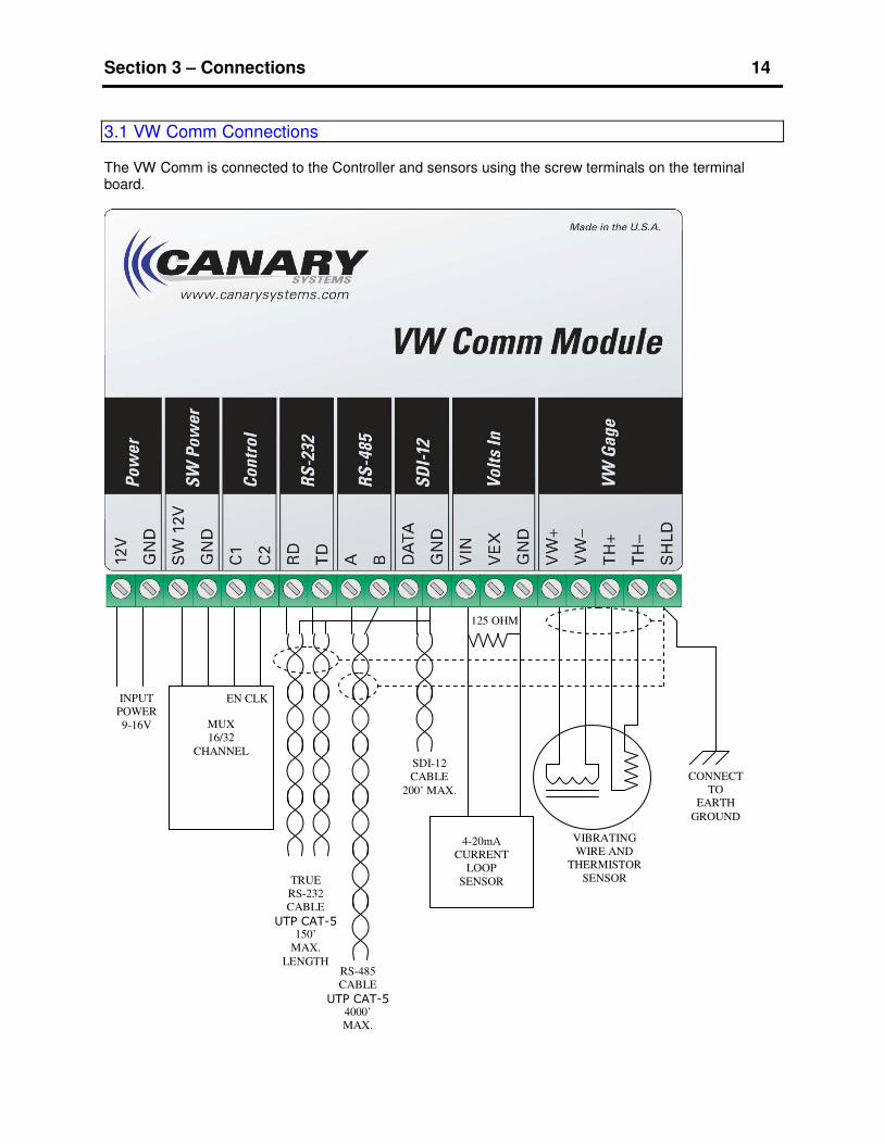
3.1 VW Comm Connections The VW Comm is connected to the Controller and sensors using the screw terminals on the terminal board.
VIBRATING
WIRE AND
THERMISTOR
SENSOR TRUE
RS-232
CABLE
UTP CAT-5 150’
MAX.
LENGTH RS-485
CABLE
UTP CAT-5
4000’
MAX.
MUX
16/32
CHANNEL
INPUT
POWER
9-16V
EN CLK
SDI-12
CABLE
200’ MAX.
125 OHM
4-20mA
CURRENT
LOOP
SENSOR
CONNECT
TO
EARTH
GROUND

Section 3 – Connections 15
Input Power is 12V DC (9-16V). The polarity must be correct (Positive to 12, Negative to GND). Do not exceed 16.2V input voltage. The power input is fused and polarity protected. Transients over 16 V should be absorbed. Continuous input power over 16.2 volts will damage the VW Comm Module. Multiplexer connections should be less than 100 feet between the VW Comm Module and the Mux. C1 is connected to the Enable (EN). C2 is connected to the clock (CLK). The 12V power to the Mux can be controlled by the SW12V terminal. RS-232 is a true “non-return to zero” signal input. Most communication ports on PC’s are “non return to zero” levels. It must be converted to TTL levels to directly interface with the control ports on loggers that do not have true RS-232 levels. SDI-12 can be used is cases where converting to true RS-232 levels is not a convenient option.
RS-485 is rated for 115.2kbps at 4000’ (1200m) of cable. This assumes quality cable, a relatively noise free environment and minimal differences in ground potential. The VW Comm Module communicates at 9600 bps so there is additional latitude to extend the network even to distances of 10000’ without the use of repeaters or isolators. The key to determining which type of communications to use, the settings of the hardware and whether additional equipment will be required will be to test the equipment in the intended environment. In battery power applications, it is important to use a termination resistor that is high impedance to reduce the current drain. The 120 ohm that is typical for RS-485 is too low in impedance. It should be 10Kohms. The problem is there is a trade off for the length of cable and the size of the termination resistor. SDI-12 interface is supported to make the VW Comm Module as though it was an SDI-Sensor. Loggers that communicate with SDI-12 devices can interface directly with the VW Comm Module. SDI-12 is connected using only two conductors, Data, and Ground. The Data Line is bi-directional. Voltage / Current input is connected to the VIN terminal. The input range is 0-2.5V (± 2.44mV, 10 bit resolution), or 4-20mA input (± 15.6uA, 10 bit resolution). The current loop must be connected with a 125 ohm, 0.1%, resistor from VIN to GND. Loop power can be connected from the 12V input power. Strain gages can be connected to the Voltage input by using the 2.5V VEX terminal. The strain gage should be the amplified type since the VW Comm has an input range of 0-2.5 Volts. Vibrating Wire sensor is connected to the VW+, VW- terminals. The VW ping and read circuit has been tested with 2000’ of cable. Shield should be connected to earth ground through the thickest wire that can fit in the terminal hole (14AWG works well). The VW Comm Module has spark gaps that must be connected to earth to be effective at discharging high voltage to earth ground. Otherwise the spark gaps will not shunt the transient energy.

Section 4 – CRBasic Programming 16
4.1 CR1000 Program Example The following example illustrates how to write custom programs for the CR1000 to read a vibrating wire sensor connected to the VW Comm Module. The program example illustrates how measurements of instruments connected to the VW Comm are read and stored in the CR1000 data table. 'CR1000 Series Datalogger Example program for the VW Comm using RS-485 Communication
'program author: Canary Systems Inc.
'This program assumes that there are VW Comm Modules at address 7,8,9
'with the following settings:
'Soft. Ver 1.25 or later
'Version Number: 1.0 or later
'Address: 37 (ASCII "7")
'Battery Active: 1 (Yes, Battery voltage is measured)
'VW Output Type: 1 (Digits)
'Voltage/Current Input Type: 1 (4-20mA Scale accross 125 ohms)
'Temp Sensor Type: 1 (on board Murata thermistor is present)
'Thermistor Type: 1 (YSI44005)
'Thermistor Output Type: 0 (degrees C)
'Temperature Output Type: 0 (degrees C)
'Comm Mode: 1 (RS-485)
'Baud Rate: 0 (9600 baud)
'VW Sample Time: 200 mSec
'Thermistor_Samples: 100 samples
'Voltage Samples: 100 samples
'Battery Samples: 100 samples
'Temperature Samples: 100 samples
'Powerdown Timeout: 20 seconds
'Start Freq: 2800.000 (adjust for sensor)
'Stop Freq: 3200.000 (adjust for sensor)
'Freq Cycles: 500.000
'The VW Comm can be adjusted using a direct RS-232 connection
'from a computer to the VW Comm at 9600 baud.
'The VW Comm remains in the RS-232 mode for several seconds after each power up.
'Sample Communication for multiple VW Comm Module's on RS-485
'7!7
'(sending 7!, and VW Comm Module responds with 7)
'8M!80045
'(sending 8M!, and VW Comm Module responds with 8 address, 004 seconds, 5 readings available)
'8D0!8+8504.73+21.691+0.000+13.016+22.094
'(sending 8D0!, and VW Comm Module responds with 8 addres,VW Digits,VW
Temperature,mAmps,BatteryVolts,VW Comm Temperature)
'8D0!8+8504.73+21.691+0.000+13.016+22.094
'7M!70045
'7D0!7+8504.28+22.216+0.000+13.068+22.393
'9M!90045
'Declare Public Variables
Public Local as float
Public count, i,j
Public PTemp, batt_volt
Public ScratchLoc(16)
Public sInBuf as string *78
Public OUT as String *78
Public IN as String *78
Public Address as String *1
Public MuxCh as String *2
Public mlReading,Reading_Loc
Public VWCommVWRead as float 'This may be in Digits, Freq, or Period
Public VWCommVWTemp as float 'This is the Thermistor in the VW Sensor
Public VWCommBatt as float 'This is the power connected to the VW Comm Module

Section 4 – CRBasic Programming 17
Public VWCommTemp as float 'This is the VW Comm Module internal temperature
Public VWCommVin as float 'This may be in volts or milliAmps
Public ActualDate as String *26
Public success as float
'Define Data Tables for each VW Comm
DataTable (VWCOMM7,TRUE,-1)
Sample(1,ActualDate,String)
'Sample(1,Address,String)
'Sample(1,MuxCh,String)
Sample (1,VWCommVWRead,IEEE4)
Sample (1,VWCommVWTemp,IEEE4)
Sample (1,VWCommBatt,IEEE4)
Sample (1,VWCommTemp,IEEE4)
Sample (1,VWCommVin,IEEE4)
EndTable
DataTable (VWCOMM8,TRUE,-1)
Sample(1,ActualDate,String)
'Sample(1,Address,String)
'Sample(1,MuxCh,String)
Sample (1,VWCommVWRead,IEEE4)
Sample (1,VWCommVWTemp,IEEE4)
Sample (1,VWCommBatt,IEEE4)
Sample (1,VWCommTemp,IEEE4)
Sample (1,VWCommVin,IEEE4)
EndTable
DataTable (VWCOMM9,TRUE,-1)
Sample(1,ActualDate,String)
'Sample(1,Address,String)
'Sample(1,MuxCh,String)
Sample (1,VWCommVWRead,IEEE4)
Sample (1,VWCommVWTemp,IEEE4)
Sample (1,VWCommBatt,IEEE4)
Sample (1,VWCommTemp,IEEE4)
Sample (1,VWCommVin,IEEE4)
EndTable
'Define Subroutines
Sub VWComm_Port_Read()
'Initialize variables so that Multilogger can identify them as overranged
VWCommVWRead=-99999
VWCommVWTemp=-99999
VWCommBatt=-99999
VWCommTemp=-99999
VWCommVin=-99999
OUT=Address+"!" 'wakeup VWComm at address from sleep mode
ScratchLoc(1)= SerialOut (7,OUT,"",5,70) ' 7 is the CR1000 code for port at C3,C4
'Check that the VW Comm is present by sending ATTN command Delay (0,100,mSec)
OUT=Address+"!" 'VW Comm at address 0
IN=Address 'VW Comm replies with address
ScratchLoc(2) =SerialOut (7,OUT,IN,10,70)
'Check for valid response
if ScratchLoc(2) <> 0 then
'Short delay
Delay (0,500,msec)
'Send Set Mux Channel command
OUT=Address+"MM"+MuxCh+"!" 'VW Comm at address ?
IN=Address+"0045" 'VW Comm Module replies with address, delay, 5 readings
ScratchLoc(10)=SerialOut (7,OUT,IN,4,70)
'Short delay
Section 4 – CRBasic Programming 18
Delay (0,500,msec)
'Send Take instrument reading command
OUT=Address+"M!" 'VW Comm Module at address ?
IN=Address+"0045" 'VW Comm Module replies with address, delay, 5 readings
ScratchLoc(10)=SerialOut (7,OUT,IN,4,70)
'Short delay
Delay (0,1000,msec)
'Make sure buffer is clear
SerialFlush(7) 'clear buffer in CR1000
Delay(0,1000,msec)
'Get Readings command
SerialOut (7,Address+"D0!","",0,0)
'Receive response
SerialIn(sInBuf,7,10,-1,78)
ScratchLoc(3) = Len(sInBuf)
if Len(sInBuf) >= 9 then
'Split out response values
Splitstr(ScratchLoc(1),sInBuf,0,12,0)
'Convert to reading
mlReading = ScratchLoc(2)
VWCommVWRead=ScratchLoc(2) 'This may be in Digits, Freq, or Period
VWCommVWTemp=ScratchLoc(3) 'This is the Thermistor in the VW Sensor
VWCommVin=ScratchLoc(4) 'This may be in volts or miliAmps
VWCommBatt=ScratchLoc(5) 'This is the power connected to the VW Comm
VWCommTemp=ScratchLoc(6) 'This is the VW Comm internal temperature
'No valid response
Else
Reading_Loc = -99999
EndIf
'Send Clear Mux Channel command
OUT=Address+"MM"+"00"+"!" 'VW Comm Module at address ?
IN=Address+"0045" 'VW Comm Module replies with address, delay, 5 readings
ScratchLoc(10)=SerialOut (7,OUT,IN,4,70)
'Short delay
Delay (0,500,msec)
Serialflush(7)
Endif 'if ScratchLoc(2) <> 0
EndSub
'***************************************************************************
'Main Program
BeginProg
Scan (15,sec,0,0) 'Scan rate every 15 seconds.
'Note that if you add more VW Comm Modules then loop time will increase
Battery (Batt_volt) 'Measure Battery voltage at the CR1000
if timeintointerval(0,2,sec) then
'Wait until 2 seconds into the interval
'Open our port
SerialOpen (7,9600,0,0,255) 'open Com2
delay(0,1000,msec)
local=count
'****************************************************
Address ="7"

Section 4 – CRBasic Programming 19
MuxCh = "00" 'Mux is not used on Address 7
SerialFlush(7)
'Wake up the VW Comms
Delay (0,1000,msec)
'Subroutine to read VW Comm Module
Call VWComm_Port_Read
ActualDate=Public.Timestamp(4,1)
Calltable VWCOMM7
Delay (0,1000,msec)
Address ="8"
MuxCh = "13" 'Mux Channel 13 (just for example)
SerialFlush(7)
'Wake up the VW Comms
Delay (0,1000,msec)
'Subroutine to read VW Comm Module
Call VWComm_Port_Read
ActualDate=Public.Timestamp(4,1)
Calltable VWCOMM8
Delay (0,1000,msec)
Address ="9"
MuxCh = "00"
SerialFlush(7)
'Wake up the VW Comms
Delay (0,1000,msec)
'Subroutine to read VW Comm Module
Call VWComm_Port_Read
ActualDate=Public.Timestamp(4,1)
Calltable VWCOMM9
Delay (0,1000,msec)
'*************************************************
'Close our serial port
Delay(0,1000,msec)
SerialClose(7)
endif 'if timeintointerval(0,2,sec)
NextScan
EndProg
Section 4 – CRBasic Programming 20
4.2 CR200 and SDI-12 Program Example 'CR200 Series Datalogger reading a generic SDI-12 Sensor using C1/SDI-12
Public batt_volt
Public mlReading
Public SDI12Data(6)
'Define Data Tables
DataTable (Test,1,-1)
DataInterval (0,15,min)
Minimum (1,batt_volt,0,0)
Minimum (1,SDI12Data(1),0,0)
Minimum (1,SDI12Data(2),0,0)
Minimum (1,SDI12Data(3),0,0)
Minimum (1,SDI12Data(4),0,0)
Minimum (1,SDI12Data(5),0,0)
Minimum (1,SDI12Data(6),0,0)
EndTable
'Main Program
BeginProg
Scan (1,Sec)
Battery (Batt_volt)
'Send wakeup command
SDI12Recorder (SDI12Data(1),"0!",1.0,0)
Delay (500,mSec)
'Send Measure command
SDI12Recorder (SDI12Data(2),"0M!",1.0,0)'measures sensor
Delay (500,mSec)
'Get measurement
'SDI12Recorder (SDI12Data(3),"0D0!",1.0,0)'Get data from sensor
mlReading = SDI12Data(2)
CallTable Test
NextScan
EndProg
Section 5 – Applications 21
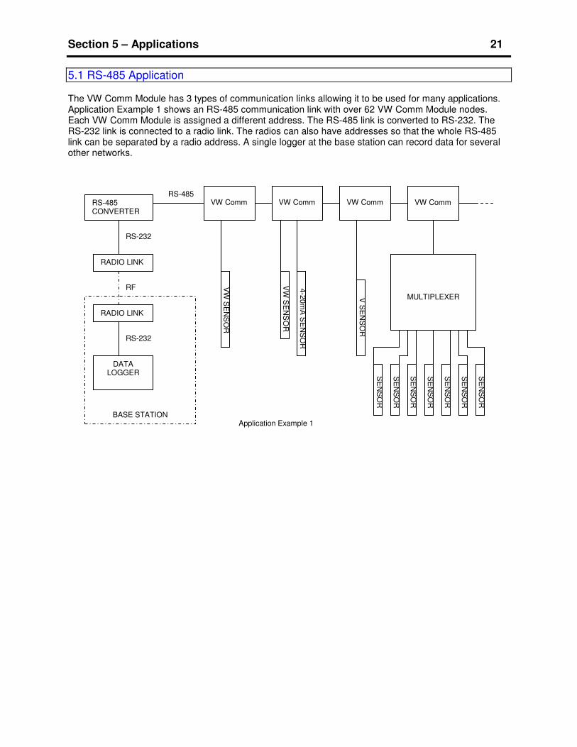
5.1 RS-485 Application The VW Comm Module has 3 types of communication links allowing it to be used for many applications. Application Example 1 shows an RS-485 communication link with over 62 VW Comm Module nodes. Each VW Comm Module is assigned a different address. The RS-485 link is converted to RS-232. The RS-232 link is connected to a radio link. The radios can also have addresses so that the whole RS-485 link can be separated by a radio address. A single logger at the base station can record data for several other networks.
VW Comm VW Comm VW Comm VW Comm
SE
NS
OR
SE
NS
OR
SE
NS
OR
SE
NS
OR
SE
NS
OR
V S
EN
SO
R
SE
NS
OR
SE
NS
OR
VW
SE
NS
OR
4-2
0m
A S
EN
SO
R
VW
SE
NS
OR
MULTIPLEXER
RADIO LINK
RS-485 RS-485 CONVERTER
RADIO LINK
RS-232
RS-232
DATA LOGGER
BASE STATION
RF
Application Example 1

Section 5 – Applications 22
5.2 SDI-12 Application
Example 2 uses an SDI-12 communication link:
VW Comm
V W
SE
NS
OR
4-2
0m
A S
EN
SO
R
VW Comm
V W
SE
NS
OR
0-2
.5V
SE
NS
OR
VW Comm
V W
SE
NS
OR
4-2
0m
A S
EN
SO
R
VW Comm
V W
SE
NS
OR
0-2
.5V
SE
NS
OR
DATA LOGGER
Application Example 2
VW Comm
V W
SE
NS
OR
4-2
0m
A S
EN
SO
R
VW Comm
V W
SE
NS
OR
0-2
.5V
SE
NS
OR
SDI-12 SDI-12
Section 5 – Applications 23
6.1 Troubleshooting Suggestions No response to communication – If the unit has been programmed for other type of connection (RS-232, RS485, SDI-12) then only that type of connection is active. If the power is cycled off and on then the unit will be in RS-232 mode at 9600 baud for 30 seconds allowing the user to change the communication setting. After the starting time, the unit changes to the communication mode stored in EEPROM memory. The best way to test communication is with a terminal program. Also, consider that the baud rate may be different. The terminal program may show unexpected characters if the baud rate is different from the com port setting. See the M8 and M9 Commands. The Vibrating Wire gage reading is not as stable as it should be – This may be due to incorrect excitation sweep settings, i.e. the specified excitation sweep is outside the range of the fundamental frequency of the gage. Use the M1 command to configure this. The manufacturer of the VW gage provides information on the best values for the start and stop frequency. The thermistor reading is not responding – The thermistor reading must be turned on using the M2 command. Vin Input reads incorrectly – The Vin can be used for either 4-20mA input or 0-2.5V. Use the M3 command to configure this input. The battery voltage reading is not responding - The battery voltage reading must be turned on using the M4 command. The internal temperature reading is not responding – The internal temperature reading must be turned on using the M5 command. The C1, C2, SW12V control is not working – Use the M6 command to control these outputs. The SW12V output has a series reset-able fuse. Disconnect the current through the device and let the fuse cool to reset. Outputs C1 and C2 are 5V logic and are limited to 15mA drive current each. Multiplexer connection to C1 and C2 is not working – Connection from C1 should be made to Mux enable (EN) and C2 should be made to Mux clock (CLK). The Mux 12V can be connected to the SW12V output. Use the MM command to control the Mux.

Section 7 – Troubleshooting 24
6.2 Querying a Radio Based VW Comm System Overview – Several brands of RS-232 serial communication radios and data modems can be used with the VW Comm. Typically, radios use AT commands to switch the destination address of the base station radio. This selects the address of the remote station radio. Once this connection is made, the base radio can control the VW Comm. In projects where the remote stations are far apart, the system can be queried from the base station. Connecting to the Base Station Radio- The radio has a 9 pin connector that may be connecter to another controller. Verify with the system manager that it is acceptable to disconnect the controller from the radio. While the controller is disconnected, no new data will be acquired and over-range values will be recorded in place. Data acquisition will continue after the controller cable is reconnected. It may be necessary to use a USB to serial converter if the laptop does not have a serial port. Make sure the correct port number is known. Test the serial port prior to this procedure so that the serial port is proven to be functional. Connect a laptop serial port to the base station radio. There is only one possible connector orientation. Setting the Base Station Address – There is a command sequence character that sets the radio into command mode. In this example the “=” character is used. Connect to the radio using a terminal program. Some terminal programs have convenient macro commands to repeat certain commands without needing to retype them. Send the following command sequence: (note <CR><LF> indicates Carriage Return, Line Feed (Enter Key)) (Wait 1 full second) === <CR><LF> (Radio Response “OK”) (Wait 1 full second) ATDT0123 <CR><LF> (Radio Response “OK”) (The address is 0123) (Wait 1 full second) ATCN<CR><LF> ( Radio Response “OK”) Now there is a connection from the laptop to the VW Comm at radio address 0123. Identifying the Remote Station – Each remote station can be identified from the base station. Send the command: 0! <CR><LF> (VW Comm Response “11CanarySyVWComm2.0500001204”) This indicates that VW Comm at SDI-12 address 0, has serial number SN1204, with firmware 2.05, is at radio address 0123. Testing the Remote Station - Each remote station can be tested from the base station. Send the command: 0MD001! <CR><LF> This causes the VW Comm to reset the mux, then set it to channel 1 and then measure all parameters. VW Comm Response “0+8816.32+19.543+0.000+12.123+24.334 1”

Section 7 – Troubleshooting 25
This indicates the VW Comm is SDI-12 address 0 (default), The VW Coil is 8816.32 digits, the piezometer temperature is 19.543 degrees C, the voltage input is 0, The Battery voltage is 12.123, the VW Comm board temperature is 24.334 degrees C and the mux channel is 1. Note only the VW Coil and piezometer thermistor are connected through the mux. Send the command: 0MD002! <CR><LF> This causes the VW Comm to reset the mux, then set it to channel 2 and then measure all parameters. VW Comm Response “0+8255.45+19.562+0.000+12.123+24.334 2” The VW Coil is 8255.45 digits, the piezometer temperature is 19.562 degrees C, the voltage input is 0, The Battery voltage is still 12.123, the VW Comm board temperature is still 24.334 degrees C and the mux channel is 2. Repeat this command for all channels. Verify that there are unique and repeatable readings for each channel. 0MD001! 0+8816.32+19.543+0.000+12.123+24.334 1 0MD001! 0+8816.32+19.543+0.000+12.123+24.334 1 0MD001! 0+8816.25+19.555+0.000+12.123+24.334 1 0MD002! 0+8255.45+19.562+0.000+12.123+24.334 2 0MD002! 0+8255.32+19.562+0.000+12.123+24.334 2 0MD002! 0+8255.45+19.555+0.000+12.123+24.334 2 0MD003! 0+7219.84+19.763+0.000+12.123+24.334 3 0MD003! 0+7219.32+19.761+0.000+12.123+24.334 3 0MD003! 0+7219.75+19.765+0.000+12.123+24.334 3 0MD004! 0+6857.95+19.222+0.000+12.123+24.334 4 0MD004! 0+6857.99+19.222+0.000+12.123+24.334 4 0MD004! 0+6857.95+19.225+0.000+12.123+24.334 4 Changing to the Next Station - Connect to the next station as follows: (Wait 1 full second) === <CR><LF> (Radio Response “OK”) (Wait 1 full second) ATDTA125 <CR><LF> (Radio Response “OK”) (The address is A125) (Wait 1 full second) ATCN<CR><LF> ( Radio Response “OK”) Now there is a connection from the laptop to the VW Comm at radio address A125. Repeat the Identify and Test Sequence for this remote station. Returning the Base Station to Normal Operation - When the query testing is complete, disconnect the laptop from the station and reconnect the controller (data logger) to the radio. Check all connections and verify the power LED’s are lit on the radio.