vxbus device driver developer's guide, 6 -...
TRANSCRIPT

VxBus
DEVICE DRIVER DEVELOPER'S GUIDE
6.9
VxBus Device Driver Developer's Guide, 6.9

Copyright © 2011 Wind River Systems, Inc.
All rights reserved. No part of this publication may be reproduced or transmitted in any form or by any means without the prior written permission of Wind River Systems, Inc.
Wind River, Tornado, and VxWorks are registered trademarks of Wind River Systems, Inc. The Wind River logo is a trademark of Wind River Systems, Inc. Any third-party trademarks referenced are the property of their respective owners. For further information regarding Wind River trademarks, please see:
www.windriver.com/company/terms/trademark.html
This product may include software licensed to Wind River by third parties. Relevant notices (if any) are provided in your product installation at the following location: installDir/product_name/3rd_party_licensor_notice.pdf.
Wind River may refer to third-party documentation by listing publications or providing links to third-party Web sites for informational purposes. Wind River accepts no responsibility for the information provided in such third-party documentation.
Corporate HeadquartersWind River500 Wind River WayAlameda, CA 94501-1153U.S.A.
Toll free (U.S.A.): 800-545-WINDTelephone: 510-748-4100Facsimile: 510-749-2010
For additional contact information, see the Wind River Web site:
www.windriver.com
For information on how to contact Customer Support, see:
www.windriver.com/support
VxBusDevice Driver Developer's Guide6.9
11 Feb 11

iii
Contents
PART I: VXBUS FUNDAMENTALS
1 Getting Started with Device Driver Development .................................... 3
1.1 About Device Drivers ..................................................................................................... 3
1.2 About this Documentation ............................................................................................ 4
1.2.1 Intended Audience ........................................................................................... 4
1.2.2 Navigating this Manual .................................................................................. 4
Experienced VxWorks Device Driver Developers ........................................ 4Novice VxWorks Device Driver Developers ................................................. 5
1.2.3 Documentation Conventions .......................................................................... 5
1.3 Additional Documentation Resources ....................................................................... 5
2 VxBus and VxBus Device Drivers ............................................................. 7
2.1 Introduction ...................................................................................................................... 7
2.2 About VxBus ................................................................................................................... 7
2.3 VxBus Device Drivers ................................................................................................... 8
2.4 Design Goals ................................................................................................................... 11
2.4.1 Performance ....................................................................................................... 11
2.4.2 Maintenance and Readability .......................................................................... 11
2.4.3 Ease of Configuration ....................................................................................... 12
2.4.4 Performance Testing ......................................................................................... 12
2.4.5 Code Size ............................................................................................................ 12
3 Device Driver Fundamentals ..................................................................... 13
3.1 Introduction ...................................................................................................................... 13

VxBusDevice Driver Developer's Guide, 6.9
iv
3.2 Driver Classes ................................................................................................................. 14
3.2.1 General Classes .................................................................................................. 14
Serial Drivers .................................................................................................... 14Storage Drivers ................................................................................................. 14Network Interface Drivers .............................................................................. 15Non-Volatile RAM Drivers ............................................................................. 15Timer Drivers .................................................................................................... 16DMA Controller Drivers ................................................................................. 16Bus Controller Drivers ..................................................................................... 16USB Drivers ....................................................................................................... 17Interrupt Controller Drivers ........................................................................... 17Multifunction Drivers ...................................................................................... 17Remote Processing Element Drivers ............................................................. 18Console Drivers ................................................................................................ 18Resource Drivers .............................................................................................. 19
3.2.2 Other Classes .................................................................................................... 19
3.3 Driver Organization ....................................................................................................... 19
3.3.1 File Location ...................................................................................................... 20
Wind River Drivers ........................................................................................... 20Third-Party Drivers .......................................................................................... 20
3.3.2 Sample Driver Files: wrsample ....................................................................... 20
3.3.3 Required Files ................................................................................................... 21
Driver Source File ............................................................................................. 21Component Description File ........................................................................... 23Driver Configuration Stub Files ..................................................................... 28README File .................................................................................................... 30Device Driver Makefiles .................................................................................. 31
3.4 VxBus Driver Methods .................................................................................................. 32
3.4.1 Representing Driver Methods in the Documentation ................................ 32
3.4.2 Parts of a Driver Method ................................................................................. 32
3.4.3 Calling Driver Methods ................................................................................... 33
3.4.4 Advertising Driver Methods .......................................................................... 34
3.4.5 Driver Method Limitations ............................................................................. 35
3.5 Driver Run-time Life Cycle .......................................................................................... 35
3.5.1 Driver Initialization Sequence ........................................................................ 35
Making Assumptions About Initialization Order ....................................... 36Early in the Boot Process ................................................................................. 36sysHwInit( ), PLB, and Hardware Discovery ............................................... 36Driver Registration ........................................................................................... 37Driver Initialization Phase 1 ........................................................................... 37Kernel Startup ................................................................................................... 38Driver Initialization Phase 2 ........................................................................... 38Driver Initialization Phase 3 ........................................................................... 38
3.5.2 Invoking a Driver Method .............................................................................. 38

Contents
v
3.5.3 Run-time Operation ......................................................................................... 39
Unloading a Driver .......................................................................................... 39Removing a Device from the System ............................................................ 39Dissociating a Device from a Driver .............................................................. 39
3.5.4 Handling a System Shutdown Notification ................................................. 40
3.5.5 Handling Late Driver Registration ................................................................ 40
3.5.6 Driver Registration Order Considerations ................................................... 41
3.5.7 Driver-to-Device Matching and Hardware Availability ............................. 41
PLB ..................................................................................................................... 42Other Bus Types ................................................................................................ 42
3.6 Services Available to Drivers ....................................................................................... 43
3.6.1 Configuration .................................................................................................... 43
Determining Driver Configuration Information ......................................... 44Responding to Changes in Device Parameters ............................................ 46
3.6.2 Memory Allocation .......................................................................................... 46
Allocating Memory During System Startup ................................................ 47Allocating Memory During Normal System Operation ............................. 48Intermixing Memory Allocation Methods within a Single Driver ........... 48
3.6.3 Non-Volatile RAM Support ............................................................................. 48
3.6.4 Hardware Access .............................................................................................. 49
Finding the Address of the Hardware Registers ......................................... 49Reading and Writing to the Hardware Registers ........................................ 50Special Requirements for Hardware Register Access ................................. 52VxBus Version Considerations ........................................................................ 52
3.6.5 Interrupt Handling ........................................................................................... 53
Overview of Interrupt Handling .................................................................... 53Interrupt Indexes .............................................................................................. 54Minimizing Work Performed Within an ISR ................................................ 54
3.6.6 Synchronization ................................................................................................ 55
Task-Level Synchronization ............................................................................ 56Interrupt-Level Synchronization .................................................................... 56
3.6.7 Direct Memory Access (DMA) ....................................................................... 58
vxbDmaBufLib .................................................................................................. 58DMA Considerations ........................................................................................ 59Allocating External DMA Engines ................................................................ 62
3.6.8 Atomic Operators ............................................................................................. 64
3.7 BSP Configuration ......................................................................................................... 65
3.7.1 Requirements for PLB Devices ....................................................................... 65
3.7.2 Configuring Device Parameters in the BSP .................................................. 67
3.8 SMP Considerations ...................................................................................................... 68
3.8.1 Lack of Implicit Locking ................................................................................. 68

VxBusDevice Driver Developer's Guide, 6.9
vi
3.8.2 True Task-to-Task Contention ......................................................................... 69
3.8.3 Interrupt Routing ............................................................................................. 69
3.8.4 Deferring Interrupt Processing ...................................................................... 69
3.9 Device Memory Mapping in 64-Bit Devices .............................................................. 71
3.10 Physical-to-Virtual Address Translations in 64-Bit VxWorks ................................. 72
3.10.1 64-bit Changes to the Memory Management Model ................................... 72
3.10.2 Porting Drivers That Rely on Physical-to-Virtual Address Translations .. 73
Transfer Using Descriptors .............................................................................. 73Strategies When Order is Unpredictable ....................................................... 74
4 Development Strategies ............................................................................. 77
4.1 Introduction ...................................................................................................................... 77
4.2 Writing New VxBus Drivers ........................................................................................ 77
4.2.1 Creating the VxBus Infrastructure ................................................................. 78
Writing Driver Source Files ............................................................................. 78Writing Header Files (Optional) .................................................................... 78Writing the Component Description File (CDF) .......................................... 78Writing the Configuration Stub Files ............................................................ 79Verifying the Infrastructure ............................................................................ 80
4.2.2 Modifying the BSP (Optional) ........................................................................ 80
4.2.3 Adding Debug Code ........................................................................................ 81
4.2.4 Adding the VxBus Driver Methods ............................................................... 81
4.2.5 Removing Global Variables ............................................................................ 82
4.3 VxBus Show Routines ................................................................................................... 83
4.3.1 Available Show Routines ................................................................................ 83
vxBusShow( ) ..................................................................................................... 83vxbDevStructShow( ) ........................................................................................ 85vxbDevPathShow( ) .......................................................................................... 86
4.3.2 PCI Show Routines .......................................................................................... 86
pciDevShow( ) ................................................................................................... 87vxbPciDeviceShow( ) ........................................................................................ 87vxbPciHeaderShow( ) ....................................................................................... 88vxbPciFindDeviceShow( ) ................................................................................ 89vxbPciFindClassShow( ) ................................................................................... 89vxbPciConfigTopoShow( ) ............................................................................... 90
4.3.3 Using Show Routines from Software ............................................................ 91
4.3.4 Configuring Show Routines into VxWorks .................................................. 93
4.4 Debugging ....................................................................................................................... 94
4.4.1 Configuring Show Routines ........................................................................... 94

Contents
vii
4.4.2 Deferring Driver Registration ........................................................................ 95
4.4.3 Including Debug Code .................................................................................... 95
4.4.4 Confirming Register Access ............................................................................ 96
4.4.5 Increasing the Size of HWMEM_POOL ........................................................ 96
4.4.6 Confirming Device and Driver Name Matches ........................................... 96
5 Driver Release Procedure .......................................................................... 97
5.1 Introduction ..................................................................................................................... 97
5.2 Driver Source Location .................................................................................................. 98
5.3 Driver-Specific Directories ............................................................................................ 98
5.4 Driver Installation and the README File ................................................................ 99
5.5 Driver Packaging ............................................................................................................ 101
5.6 Driver Release Procedure ............................................................................................. 101
PART II: DEVICE DRIVER PORTING
6 Class-Specific Driver Development .......................................................... 105
6.1 About VxBus Driver Classes ........................................................................................ 105
6.2 Before You Begin ............................................................................................................. 105
6.3 About the Class-Specific Driver Documentation ..................................................... 106
7 Bus Controller Drivers ................................................................................ 107
7.1 Introduction ..................................................................................................................... 107
7.2 Overview .......................................................................................................................... 107
7.3 VxBus Driver Methods .................................................................................................. 109
7.3.1 {busCtlrDevCfgRead}( ) ................................................................................... 109
7.3.2 {busCtlrCfgRead}( ) ........................................................................................... 110
7.3.3 {busCtlrDevCfgWrite}( ) ................................................................................... 111
7.3.4 {busCtlrCfgWrite}( ) .......................................................................................... 111
7.3.5 {busCtlrDevCtlr}( ) ............................................................................................ 112
7.3.6 {busCtlrAccessOverride}( ) .............................................................................. 113
Override for (*busCfgRead)( ) ......................................................................... 114Override for (*busCfgWrite)( ) ........................................................................ 114Override for (*vxbDevControl)( ) ................................................................... 114
VxBusDevice Driver Developer's Guide, 6.9
viii
7.3.7 {busCtlrCfgInfo}( ) ............................................................................................. 115
7.3.8 {busCtlrBaseAddrCvt}( ) .................................................................................. 115
7.3.9 {vxbDevRegMap}( ) ........................................................................................... 116
Specifying a Predefined Transaction Type ..................................................... 117Providing a New Transaction Type ............................................................... 119
7.3.10 {vxbIntDynaVecProgram}( ) ............................................................................. 120
7.4 Header Files ..................................................................................................................... 121
7.5 BSP Configuration .......................................................................................................... 121
7.5.1 PCI Configuration ............................................................................................ 122
7.5.2 PCI Autoconfiguration .................................................................................... 123
7.6 Available Utility Routines ............................................................................................ 123
7.6.1 PCI Configuration ............................................................................................ 124
7.6.2 PCI Autoconfiguration ..................................................................................... 124
7.6.3 vxbBusAnnounce( ) ........................................................................................... 125
7.6.4 vxbPciBusTypeInit( ) ......................................................................................... 125
7.7 Initialization .................................................................................................................... 126
7.7.1 Initialization Example ..................................................................................... 127
vxbBusAnnounce( ) ........................................................................................... 128vxbDeviceAnnounce( ) ..................................................................................... 128vxbDevStructAlloc( ) ........................................................................................ 128vxbDevStructFree( ) .......................................................................................... 128
7.8 Debugging ........................................................................................................................ 129
8 Direct Memory Access Drivers .................................................................. 131
8.1 Introduction ..................................................................................................................... 131
8.2 Overview ........................................................................................................................... 131
8.3 VxBus Driver Methods ................................................................................................... 132
8.3.1 {vxbDmaResourceGet}( ) .................................................................................. 132
8.3.2 {vxbDmaResourceRelease}( ) ........................................................................... 133
8.3.3 {vxbDmaResDedicatedGet}( ) .......................................................................... 133
8.4 Header Files ...................................................................................................................... 133
8.5 BSP Configuration .......................................................................................................... 134
8.6 Available Utility Routines ............................................................................................. 134
8.7 Initialization ..................................................................................................................... 134

Contents
ix
8.8 DMA System Structures and Routines ....................................................................... 134
8.8.1 (*dmaRead)( ) ..................................................................................................... 135
8.8.2 (*dmaReadAndWait)( ) ..................................................................................... 135
8.8.3 (*dmaWrite)( ) .................................................................................................... 135
8.8.4 (*dmaWriteAndWait)( ) .................................................................................... 135
8.8.5 (*dmaCancel)( ) .................................................................................................. 136
8.8.6 (*dmaPause)( ) ................................................................................................... 136
8.8.7 (*dmaResume)( ) ................................................................................................ 136
8.8.8 (*dmaStatus)( ) ................................................................................................... 136
8.9 Debugging ....................................................................................................................... 137
9 Interrupt Controller Drivers ........................................................................ 139
9.1 Introduction ..................................................................................................................... 139
9.2 Overview .......................................................................................................................... 140
Interrupt Identification .................................................................................... 140Interrupt Controller Driver Responsibilities ................................................. 140Interrupt Controller Configurations ............................................................... 141Dynamic Vectors ................................................................................................ 141Interrupt Controller Drivers and Multiprocessing ....................................... 142
9.3 VxBus Driver Methods .................................................................................................. 142
9.3.1 Basic Methods .................................................................................................... 142
{vxbIntCtlrConnect}( ) ...................................................................................... 142{vxbIntCtlrDisconnect}( ) ................................................................................. 142{vxbIntCtlrEnable}( ) ......................................................................................... 143{vxbIntCtlrDisable}( ) ........................................................................................ 143
9.3.2 Dynamic Vector Methods ................................................................................ 143
{vxbIntDynaVecConnect}( ) ............................................................................. 143
9.3.3 Multiprocessor Methods ................................................................................. 144
{vxbIntCtlrIntReroute}( ) .................................................................................. 144{vxbIntCtlrCpuReroute}( ) .............................................................................. 144{vxIpiControlGet}( ) .......................................................................................... 145
9.4 Header Files ...................................................................................................................... 145
vxbIntrCtlr.h ....................................................................................................... 145vxbIntCtlrLib.h .................................................................................................. 145
9.5 BSP Configuration .......................................................................................................... 146
9.5.1 Interrupt Input Table ........................................................................................ 146
9.5.2 Dynamic Vector Table ....................................................................................... 148
9.5.3 CPU Routing Table ............................................................................................ 148
9.5.4 Interrupt Priority ............................................................................................... 149

VxBusDevice Driver Developer's Guide, 6.9
x
9.5.5 Crossbar Routing Table .................................................................................... 150
9.6 Available Utility Routines ............................................................................................. 150
9.6.1 intCtlrHwConfGet( ) ......................................................................................... 151
9.6.2 intCtlrISRAdd( ) ................................................................................................ 151
9.6.3 intCtlrISRDisable( ) ........................................................................................... 152
9.6.4 intCtlrISREnable( ) ............................................................................................ 152
9.6.5 intCtlrISRRemove( ) .......................................................................................... 152
9.6.6 intCtlrPinFind( ) ................................................................................................ 152
9.6.7 intCtlrTableArgGet( ) ........................................................................................ 152
9.6.8 intCtlrTableFlagsGet( ) ..................................................................................... 152
9.6.9 intCtlrTableIsrGet( ) .......................................................................................... 152
9.6.10 intCtlrHwConfShow( ) ..................................................................................... 153
9.6.11 intCtlrTableCreate( ) ......................................................................................... 153
9.6.12 intCtlrTableFlagsSet( ) ...................................................................................... 153
9.6.13 intCtlrTableUserSet( ) ....................................................................................... 153
9.6.14 VXB_INTCTLR_ISR_CALL( ) ......................................................................... 153
9.6.15 VXB_INTCTLR_PINENTRY_ENABLED( ) ................................................... 153
9.6.16 VXB_INTCTLR_PINENTRY_ALLOCATED( ) ............................................. 154
9.6.17 Dispatch Routines ............................................................................................. 154
vxbIntDynaCtlrInputInit( ) .............................................................................. 154vxbIntDynaVecProgram( ) ............................................................................... 155
9.7 Initialization ..................................................................................................................... 155
9.8 Interrupt Controller Topologies and Hierarchies ..................................................... 155
9.9 Interrupt Priority ............................................................................................................. 156
9.10 ISR Dispatch .................................................................................................................... 157
9.11 Managing Dynamic Interrupt Vectors ........................................................................ 159
Configuring Dynamic Vectors Using the Service Driver Routines ............ 160Configuring Dynamic Vectors in the BSP ..................................................... 160Programming Dynamic Vectors ...................................................................... 161Determining Dynamic Vector Values ............................................................ 161
9.12 Internal Representation of Interrupt Inputs .............................................................. 162
9.13 Multiprocessor Issues with VxWorks SMP ................................................................ 163
9.13.1 Routing Interrupt Inputs to Individual CPUs .............................................. 163
9.13.2 Interprocessor Interrupts ................................................................................. 164
9.13.3 Limitations in Multiprocessor Systems .......................................................... 168

Contents
xi
9.14 Debugging ........................................................................................................................ 168
10 Multifunction Drivers .................................................................................. 169
10.1 Introduction ...................................................................................................................... 169
10.2 Overview ........................................................................................................................... 169
10.3 VxBus Driver Methods ................................................................................................... 170
10.4 Header Files ...................................................................................................................... 170
10.5 BSP Configuration .......................................................................................................... 170
10.6 Available Utility Routines ............................................................................................. 171
vxbDevStructAlloc( ) ........................................................................................ 171vxbDeviceAnnounce( ) ..................................................................................... 171vxbDevRemovalAnnounce( ) .......................................................................... 171vxbDevStructFree( ) .......................................................................................... 171vxbBusAnnounce( ) ........................................................................................... 172
10.7 Initialization ..................................................................................................................... 172
10.8 Device Interconnections ................................................................................................ 172
10.8.1 Interleaved Registers ........................................................................................ 172
10.8.2 Shared Resources ............................................................................................... 173
10.8.3 Other Interactions ............................................................................................. 173
10.9 Logical Location of Subordinate Devices ................................................................... 174
10.10 Debugging ........................................................................................................................ 174
11 Network Drivers .......................................................................................... 175
11.1 Introduction ...................................................................................................................... 175
11.1.1 Terminology ....................................................................................................... 175
11.1.2 Networking Overview ..................................................................................... 176
Seven Layer OSI Model .................................................................................... 176Transmission Media and VxWorks ................................................................. 176Protocols ............................................................................................................. 177
11.2 Network Interface Drivers ............................................................................................. 177
11.2.1 Network Interface Driver Overview .............................................................. 177
IPNET-Native Drivers ...................................................................................... 177Functional Modules .......................................................................................... 178Network Driver Interrupts ............................................................................. 179
11.2.2 VxBus Driver Methods for Network Interface Drivers .............................. 180
{muxDevConnect}( ) ......................................................................................... 180{muxDevConnect2}( ) ....................................................................................... 181
VxBusDevice Driver Developer's Guide, 6.9
xii
{vxbDrvUnlink}( ) .............................................................................................. 183{miiMediaUpdate}( ) ......................................................................................... 183{miiRead}( ) ........................................................................................................ 184{miiWrite}( ) ........................................................................................................ 185
11.2.3 Header Files for Network Interface Drivers ................................................. 185
11.2.4 BSP Configuration for Network Interface Drivers ...................................... 186
11.2.5 Available Utility Routines for Network Interface Drivers ......................... 187
MUX Interactions .............................................................................................. 187Job Queueing ..................................................................................................... 188Buffer Management .......................................................................................... 189DMA Support .................................................................................................... 193PHY and MII bus interactions ......................................................................... 194
11.2.6 Initialization for Network Interface Drivers ................................................ 196
11.2.7 MUX: Connecting to Networking Code ........................................................ 196
11.2.8 jobQueueLib: Deferring ISRs ........................................................................... 197
11.2.9 Working with Ipcom_pkt Packets ................................................................... 198
Supporting Scatter-Gather with IPNET-Native Drivers .............................. 201
11.2.10 netBufLib: Transferring Data with M_BLKs ................................................ 202
11.2.11 Protocol Impact on Drivers .............................................................................. 204
11.2.12 Other Network Interface Driver Issues .......................................................... 216
Receive Handling Method ............................................................................... 217Receive Stall Handling ..................................................................................... 224
11.2.13 Debugging Network Interface Drivers .......................................................... 225
Using VxBus Show Routines ........................................................................... 225Deferring Driver Registration ......................................................................... 225Pairing with a PHY instance ............................................................................ 226Stress Testing ...................................................................................................... 226Netperf Test Suite .............................................................................................. 227Interrupt Validation .......................................................................................... 227Additional Tests ................................................................................................. 227
11.3 PHY Drivers ...................................................................................................................... 233
11.3.1 PHY Driver Overview ...................................................................................... 234
PHY Device Probing and Discovery .............................................................. 234MAC and MII Bus Relationship ...................................................................... 235Generic PHY Driver Support ........................................................................... 236Generic TBI Driver Support ............................................................................. 236
11.3.2 VxBus Driver Methods for PHY Drivers ....................................................... 237
Upper Edge Methods ........................................................................................ 237Lower Edge Methods ....................................................................................... 237
11.3.3 Header Files for PHY Drivers ......................................................................... 239
11.3.4 BSP Configuration for PHY Drivers ............................................................... 239

Contents
xiii
11.3.5 Available Utility Routines for PHY Drivers .................................................. 239
Upper Edge Utility Routines ........................................................................... 240Lower Edge Utility Routines ........................................................................... 240
11.3.6 Initialization for PHY Drivers ......................................................................... 241
11.3.7 Debugging PHY Drivers .................................................................................. 241
11.4 Wireless Ethernet Drivers .............................................................................................. 242
11.5 Hierarchical END Drivers ............................................................................................. 242
12 Non-Volatile RAM Drivers .......................................................................... 243
12.1 Introduction ...................................................................................................................... 243
NVRAM Drivers and TrueFFS ........................................................................ 243
12.2 Non-Volatile RAM Drivers ........................................................................................... 244
12.2.1 NVRAM Driver Overview ............................................................................... 244
12.2.2 VxBus Driver Methods for NVRAM Drivers ................................................ 244
{nonVolGet}( ) .................................................................................................... 244{nonVolSet}( ) ..................................................................................................... 245
12.2.3 Header Files ....................................................................................................... 245
12.2.4 BSP Configuration for NVRAM Drivers ....................................................... 245
12.2.5 Utility Routines for NVRAM Drivers ............................................................ 246
12.2.6 Initialization for NVRAM Drivers .................................................................. 246
12.2.7 NVRAM Block Sizes ......................................................................................... 246
12.2.8 Stacking NVRAM Instances ............................................................................ 247
12.2.9 Debugging NVRAM Drivers ........................................................................... 247
12.3 Flash File System Support with TrueFFS ................................................................... 247
12.3.1 TrueFFS Overview ............................................................................................. 248
Core Layer .......................................................................................................... 248MTD Layer ........................................................................................................ 248Socket Layer ....................................................................................................... 248Flash Translation Layer .................................................................................... 249
12.3.2 TrueFFS Driver Development Process ........................................................... 249
Using MTD-Supported Flash Devices ........................................................... 249Writing MTD Components .............................................................................. 252Socket Drivers .................................................................................................... 260Flash Translation Layer .................................................................................... 266
13 Resource Drivers ........................................................................................ 281
13.1 Introduction ...................................................................................................................... 281
13.2 Overview ........................................................................................................................... 281

VxBusDevice Driver Developer's Guide, 6.9
xiv
13.3 VxBus Driver Methods ................................................................................................... 282
13.4 Header Files ...................................................................................................................... 282
13.5 BSP Configuration .......................................................................................................... 282
13.6 Available Utility Routines ............................................................................................. 283
13.7 Initialization ..................................................................................................................... 283
13.8 Debugging ........................................................................................................................ 283
14 Serial Drivers ............................................................................................... 285
14.1 Introduction ...................................................................................................................... 285
14.2 Overview ........................................................................................................................... 285
14.3 VxBus Driver Methods ................................................................................................... 286
14.3.1 {sioChanGet}( ) ................................................................................................... 286
14.3.2 {sioChanConnect}( ) .......................................................................................... 287
14.4 Header Files ...................................................................................................................... 287
14.5 BSP Configuration .......................................................................................................... 288
14.6 Available Utility Routines ............................................................................................. 288
14.7 Initialization ..................................................................................................................... 288
14.8 Polled Mode Versus Interrupt-Driven Mode ............................................................. 288
14.9 SIO_CHAN and SIO_DRV_FUNCS ............................................................................ 289
14.10 WDB ................................................................................................................................... 291
14.10.1 WDB and Kernel Initialization ........................................................................ 291
14.11 Serial Drivers, Initialization, and Interrupts ............................................................. 291
14.11.1 WDB and Interrupts ......................................................................................... 292
14.11.2 Initialization Order and Interrupts ................................................................. 292
14.11.3 Initialization Order ........................................................................................... 293
14.12 Debugging ........................................................................................................................ 293
15 Storage Drivers ........................................................................................... 295
15.1 Introduction ...................................................................................................................... 295
15.2 Overview ........................................................................................................................... 295
15.3 VxBus Driver Methods ................................................................................................... 296

Contents
xv
15.4 Header Files ...................................................................................................................... 296
15.5 BSP Configuration .......................................................................................................... 296
15.6 Available Utility Routines ............................................................................................. 297
erfHandlerRegister( ) and erfHandlerUnregister( ) ..................................... 297erfEventRaise( ) ................................................................................................. 297xbdAttach( ) ....................................................................................................... 297bio_done( ) .......................................................................................................... 297
15.7 Initialization ..................................................................................................................... 297
15.8 Interface with VxWorks File Systems ......................................................................... 298
15.8.1 Device Creation ................................................................................................. 298
ERF Registration ................................................................................................ 298Advertisement of XBD Methods ..................................................................... 299ERF New Device Notification ......................................................................... 300
15.8.2 Processing ........................................................................................................... 300
15.8.3 Event Reporting ................................................................................................. 301
15.9 Writing New Storage Drivers ........................................................................................ 302
15.10 Debugging ........................................................................................................................ 303
16 Timer Drivers ............................................................................................... 305
16.1 Introduction ...................................................................................................................... 305
16.2 Overview ........................................................................................................................... 305
16.3 VxBus Driver Methods ................................................................................................... 306
16.4 Header Files ...................................................................................................................... 309
16.5 BSP Configuration .......................................................................................................... 309
16.6 Available Utility Routines ............................................................................................. 309
16.7 Initialization ..................................................................................................................... 309
16.8 Data Structure Layout ..................................................................................................... 310
16.9 Implementing Driver Service Routines ...................................................................... 311
16.9.1 (*timerAllocate)( ) .............................................................................................. 311
16.9.2 (*timerRelease)( ) ............................................................................................... 311
16.9.3 (*timerRolloverGet)( ) ....................................................................................... 312
16.9.4 (*timerCountGet)( ) ........................................................................................... 312
16.9.5 (*timerDisable)( ) ............................................................................................... 313
16.9.6 (*timerEnable)( ) ................................................................................................ 314

VxBusDevice Driver Developer's Guide, 6.9
xvi
16.9.7 (*timerISRSet)( ) ................................................................................................. 314
16.9.8 (*timerEnable64)( ) ............................................................................................ 315
16.9.9 (*timerRolloverGet64)( ) ................................................................................... 315
16.9.10 (*timerCountGet64)( ) ....................................................................................... 316
16.10 Integrating a Timer Driver ............................................................................................ 317
16.10.1 VxWorks System Clock .................................................................................... 317
16.10.2 VxWorks Auxiliary Clock ................................................................................ 319
16.10.3 VxWorks Timestamp Driver ............................................................................ 320
16.11 Debugging ........................................................................................................................ 321
16.12 SMP Considerations ....................................................................................................... 321
17 USB Drivers ................................................................................................. 323
17.1 Introduction ...................................................................................................................... 323
17.2 Wind River USB Overview ............................................................................................ 323
17.2.1 USB Host Stack Drivers .................................................................................... 324
VxBus Model Drivers ....................................................................................... 324Other Host Drivers ............................................................................................ 324
17.2.2 USB Target Stack ............................................................................................... 324
17.3 Host Controller and Root Hub Class Drivers ............................................................ 324
17.3.1 VxBus Driver Methods ..................................................................................... 325
17.3.2 Header Files ....................................................................................................... 325
17.3.3 BSP Configuration ............................................................................................. 326
17.3.4 Available Utility Routines ................................................................................ 327
17.3.5 Initialization ....................................................................................................... 327
17.3.6 Debugging .......................................................................................................... 328
18 Other Driver Classes .................................................................................. 331
18.1 Introduction ...................................................................................................................... 331
18.2 Overview ........................................................................................................................... 331
18.3 VxBus Driver Methods ................................................................................................... 332
18.4 Header Files ...................................................................................................................... 333
18.5 BSP Configuration .......................................................................................................... 333
18.6 Available Utility Routines ............................................................................................. 333
18.7 Initialization ..................................................................................................................... 333

Contents
xvii
18.8 Debugging ........................................................................................................................ 334
PART III: DEVICE DRIVER PORTING
19 Legacy Drivers and Migration ................................................................... 337
19.1 Migration Overview ....................................................................................................... 337
19.2 Legacy Driver Overview ................................................................................................ 337
20 Migrating to VxBus ..................................................................................... 339
20.1 Overview ........................................................................................................................... 339
20.2 Available Resources ........................................................................................................ 339
Template Drivers ............................................................................................... 339
20.3 Porting an Existing VxWorks Driver to VxBus .......................................................... 340
20.3.1 Verifying Your Hardware and Driver Code .................................................. 340
20.3.2 Creating the VxBus Infrastructure ................................................................. 341
Driver Source File ............................................................................................. 341Driver Header Files (Optional) ...................................................................... 341Driver Component Description File .............................................................. 342Driver Configuration Stub Files ..................................................................... 343Modifying the BSP (Optional) ........................................................................ 344Verifying the infrastructure ............................................................................. 345
20.3.3 Moving Existing Code into the New Source File ........................................ 346
20.3.4 Removing Driver Code from the BSP ........................................................... 347
20.3.5 Adding Debug Code ........................................................................................ 347
20.3.6 Changing Initialization to VxBus ................................................................... 348
20.3.7 Adding VxBus Driver Methods ..................................................................... 351
20.3.8 Updating Names Within the Source File ...................................................... 352
20.3.9 Removing BSP Dependencies ........................................................................ 352
20.3.10 Converting Register Access in Existing Code .............................................. 355
20.3.11 Removing Global Variables ............................................................................ 355
21 Migrating to IPNET-Native Drivers ............................................................. 357
21.1 Introduction ...................................................................................................................... 357
21.2 Converting an Existing END Driver to an IPNET-Native Driver .......................... 358
21.3 Updating the Driver to use IPNET-Native Infrastructure ....................................... 358
21.4 Updating Driver Routines ............................................................................................. 364
VxBusDevice Driver Developer's Guide, 6.9
xviii
21.5 Building, Integrating, and Testing Your Driver ........................................................ 379
PART IV: APPENDICES
A Glossary ...................................................................................................... 385
B Checklist for Device Drivers ...................................................................... 389
C IPNET-Native Migration Checklist .............................................................. 391
Index .................................................................................................................... 397

1
PAR T I
VxBus Fundamentals
1 Getting Started with Device Driver Development .................. 3
2 VxBus and VxBus Device Drivers ........................................... 7
3 Device Driver Fundamentals ................................................... 13
4 Development Strategies .......................................................... 77
5 Driver Release Procedure ........................................................ 97

VxBusDevice Driver Developer's Guide, 6.9
2

3
1Getting Started with
Device Driver Development
1.1 About Device Drivers 3
1.2 About this Documentation 4
1.3 Additional Documentation Resources 5
1.1 About Device Drivers
In the simplest terms, VxWorks device drivers are a means of communication between a hardware device and the VxWorks operating system. In VxWorks 6.x releases, device drivers can be implemented in one of two ways: as VxBus-enabled device drivers or as legacy (pre-VxBus) device drivers. However, the preferred method for new development uses the VxBus device driver infrastructure. This is especially true if you are developing for a symmetric multiprocessing (SMP) system.1
The VxBus infrastructure supports device drivers by defining standard interfaces for the driver to interact with the operating system and device hardware. Thus, VxBus drivers share a common interface to the operating system or hardware.
20. Migrating to VxBus includes information on migrating an existing legacy-model driver to the VxBus model.
1. Wind River does not provide legacy model drivers that are SMP safe. You are responsible to ensure that such a driver is SMP safe. For information on SMP support, see the VxWorks Kernel Programmer’s Guide: VxWorks SMP.
NOTE: Documentation on legacy model device drivers is available on OLS.

VxBusDevice Driver Developer's Guide, 6.9
4
1.2 About this Documentation
This section provides information on the intended audience for this documentation, including the level of expertise expected from the developer. It also provides a map of this documentation to help you get the information you need regarding device driver development quickly and efficiently.
1.2.1 Intended Audience
This documentation is primarily designed for the experienced device driver developer. In general, the documentation does not assume specific experience with VxWorks device drivers or with the VxBus device driver model. However, it does assume general experience writing device drivers for embedded hardware systems (for example, a basic understanding of reading and writing device registers).
1.2.2 Navigating this Manual
Part I: VxBus Fundamentals These chapters provide information and concepts that are fundamental to the development of most VxBus model device drivers. They serve as a foundation for the class-specific information presented in Part II.
Part II: Class-Specific Device Drivers These chapters provide specific information and requirements for class-specific device drivers for all driver classes supported by VxWorks (for example, network drivers, bus controller drivers, USB drivers, and so forth).
Part III: Device Drivers These chapters describe how to migrate any existing drivers to the VxBus model.
Part IV: Appendices These appendix chapters provide a glossary and checklists for you to use for deployment and distribution, or for migration.
Experienced VxWorks Device Driver Developers
Your level of experience with VxWorks device driver development will influence how you approach this document. If your experience is limited to legacy model VxWorks device driver development, the majority of the concepts described in this document will be new to you. Understanding these concepts is critical before beginning any VxBus model driver development. If you are an experienced VxBus device driver developer, some of the information in Part I is likely to be familiar to you. However, you may still need to carefully review the requirements for your driver class in Part II and may even need to review certain concepts in Part I.
It is also critical that you carefully examine Part I and relevant chapters of Part II before beginning any VxBus model driver development.

1 Getting Started with Device Driver Development1.3 Additional Documentation Resources
5
Novice VxWorks Device Driver Developers
If you are fairly new to VxWorks device driver development, the fundamentals presented in Part I are critical for most VxBus model device drivers. Once you have a basic understanding of these fundamentals, you can move on to the class-specific information in Part II that is appropriate for your device class.
If you are new to device driver development in general (not specific to VxWorks), you may need to consult some third-party information in order to better understand the basic concepts associated with all device driver development. However, if you are fairly experienced with embedded development and have some hardware experience, you should find that the information in Part I is sufficient to get you started.
1.2.3 Documentation Conventions
The following conventions are used in this document:
installDir Within this document, file paths are typically expressed as a full path; this practice maintains consistency between this and other Wind River documentation. For example:
installDir/vxworks-6.x/target/src/hwif/sio/Makefile
bspname In several places within this document, there are references to filenames that are based on the BSP. These filenames have the string bspname substituted. For example, if you are working on a BSP called acmeBSP, change any reference bspname to acmeBSP. For example, bspname.h would become acmeBSP.h.
class Drivers for specific devices are grouped by device class. For example, serial drivers are located at:
installDir/vxworks-6.x/target/src/hwif/sio
For the general case, class represents the device type. For example:
installDir/vxworks-6.x/target/src/hwif/class
dev Where this document refers to devices in general, these devices are generically referred to as dev. In such cases, substitute the name of each device or device type for dev. For example, if your driver supports ncr810, the general file devInit.c becomes ncr810Init.c.
1.3 Additional Documentation Resources
Before beginning any device-driver development, you should have a good understanding of the overall VxWorks I/O system. For more information, see the VxWorks Kernel Programmer's Guide: I/O System.

VxBusDevice Driver Developer's Guide, 6.9
6
In addition, you may want to refer to the VxWorks BSP Developer’s Guide. This document discusses VxWorks BSP development. In particular, it provides guidelines for writing a custom BSP based on an existing reference BSP.

7
2VxBus and VxBus Device Drivers
2.1 Introduction 7
2.2 About VxBus 7
2.3 VxBus Device Drivers 8
2.4 Design Goals 11
2.1 Introduction
This chapter explains some of the key concepts and terms associated with VxBus and VxBus device drivers including the term VxBus itself, instances, and driver method advertisement. This chapter is intended as a system overview only. The concepts and terms introduced here are explained further in 3. Device Driver Fundamentals.
Class-specific driver information for all supported VxBus classes is provided in Part II: Class-Specific Device Drivers.
2.2 About VxBus
The term VxBus generally refers to one of two things. In general, it refers to a specific infrastructure for support of device drivers in VxWorks, with minimal BSP support. This includes functionality to allow device drivers to be matched up with devices, mechanisms for drivers to gain access to device hardware, a mechanism for other parts of the software environment to gain access to device functionality, and other functionality required in order for device drivers to be functional in a VxWorks system.
In addition, the term VxBus sometimes refers to a set of components of the VxWorks operating system for use with Workbench, the vxprj command-line utility, and VxWorks image projects (VIPs). The core VxBus functionality is one component, each VxWorks VxBus driver is a component, and the VxBus support

VxBusDevice Driver Developer's Guide, 6.9
8
modules are components. Each of these components can be selected individually from within Workbench.
Before the first release of VxBus with VxWorks 6.2, device drivers were not integrated with VxWorks project configuration, and to add and remove support for specific devices required significant knowledge of the BSP and of the driver, as well as requiring extra effort to manage VxWorks projects when drivers needed to be added or removed. As a set of components, VxBus eliminates most of that by allowing various drivers and support modules to be selected from within Workbench, without requiring knowledge of the BSP and driver, and without requiring extra effort for management of VxWorks projects when drivers are added or removed.
Many BSPs are released in a format in which VxBus is required. If you remove the VxBus component from projects based on these BSPs, your project does not build.
2.3 VxBus Device Drivers
There are three terms that are important for understanding VxBus device drivers: device, driver, and instance. The term device refers to a bit of hardware. The term driver refers to the executable code plus the configuration information required to make the hardware device accessible to the OS. Each driver can be associated with zero or more devices. The term instance refers to one such association. Figure 2-1 illustrates this pairing.
Driver methods make up the mechanism for other parts of the software environment to gain access to device functionality.
Figure 2-1 VxBus Instance
USBPort
SerialPort
SerialPort
NetworkPort
ns16550.c
register( )
{
}
.
.
.
Driver
Devices
A driver and a
device are paired
together to form
an instance.

2 VxBus and VxBus Device Drivers2.3 VxBus Device Drivers
9
When using a driver method, the module making the request can query a single instance or all instances. And the query can either ask for information on how to accomplish an action or it can be a request for the driver to perform some action. At the top level, then, the query can consist of a question of whether a specific instance can support an action, a question of what instances can support an action, or a request to perform an action.
Figure 2-2 illustrates communication between the device, driver, and operating system in a subset of a VxWorks system. The system shown includes two middleware modules or VxWorks subsystems (in this case, the network stack and the auxiliary timer) which are attempting to communicate with a hardware device on the system. Note that an actual system is likely to have several instances and many middleware modules, Figure 2-2 is a subset only.
Figure 2-2 Method Advertising
ns16550 Serial Port
OpenPic Timer
{sioChanGet}( )
{sioChanConnect}( )
{vxbTimerFuncGet}( )
Yukon II Network Interface
{muxDevConnect}( )
{vxbDevShow}( )
...
{vxbIntCtlrConnect}( )
{vxbIntCtlrEnable}( )
...
Interrupt Controller
Support for
{vxbTimerFuncGet}( )
Support for
{muxDevConnect}( )
Network Stack Auxiliary Clock
vxbDevMethodGet( )vxbDevMethodGet( )
Yes
Device Driver Pairings (instances) Middleware ModuleMiddleware Module
other instances ... other modules...other modules...
??
Yes

VxBusDevice Driver Developer's Guide, 6.9
10
An instance makes itself available to the overall VxWorks system by advertising the driver methods it supports. In Figure 2-2, the network stack uses the vxbDevMethodGet( ) routine to query each instance (device/driver pairing) known to the system. In the example, the network stack module is searching for an instance that supports the {muxDevConnect}( ) driver method. If the instance supports the method, it returns a pointer to the driver’s routine implementing that method. If an instance does not support the requested method, it returns NULL. In the example shown, the stack finds a Yukon II network interface advertising support for the required method.
The system also shows an auxiliary timer making a similar query. In this case, the timer looks for the {vxbTimerFuncGet}( ) method and gets a positive response from the OpenPic timer instance in the system.
Note that although this example shows only a single instance making a positive response in each case, any number of instances (or none at all) can include the necessary support.
Figure 2-3 Known Instance Method Discovery
ns16550 Serial Port
OpenPic Timer
{sioChanGet}( )
{sioChanConnect}( )
{vxbTimerFuncGet}( )
Yukon II Network Interface
{muxDevConnect}( )
{vxbDevShow}( )
...
{vxbIntCtlrConnect}( )
{vxbIntCtlrEnable}( )
...
Interrupt Controller
other instances ...
Support for
{vxbIntCtlrEnable}( )
vxbDevMethodGet( )
Yes
?

2 VxBus and VxBus Device Drivers2.4 Design Goals
11
Figure 2-3 shows the OpenPic timer instance (as seen in Figure 2-2) querying the interrupt controller instance directly. The interrupt controller includes support for {vxbIntCtlrEnable}( ) and therefore responds to the timer request.
2.4 Design Goals
VxWorks is an operating system for real-time and embedded applications. This places some constraints on the design of device drivers.
The primary goal for most VxWorks drivers is real-time performance of the target system as a whole. In general, if a driver does not allow real-time execution of applications running on the target, the driver is a poor choice for use with VxWorks and another driver should be selected. Depending on the application, this may be an absolute requirement, or it may be an important consideration.
Memory footprint is another constraint for VxWorks drivers. Many embedded applications have limited memory and because demand paging to disk is not compatible with real-time operation, memory constraints are extremely important.
Standard software requirements are also important in the VxWorks environment. This includes requirements such as driver flexibility, code maintainability, code readability, and driver configurability.
2.4.1 Performance
Drivers must perform well enough to match the real-time kernel's abilities. Designing for performance implies many things. First, it requires using direct memory access (DMA) and interrupts in an efficient manner. This requires you to keep your routine nesting at an optimum level. For example, too many routine calls and restore operations can increase process dispatch latency and reduce performance. However, performance requirements must be balanced against proper use of routines for keeping code size small and making your driver design easy to follow and understand.
Designing for performance also means keeping interrupt latency to a minimum. Interrupt handlers must receive the greatest care in any design. Overall system performance is just as important as the specific driver's performance.
For specific applications, you may consider it acceptable to write a VxWorks driver that sacrifices one or more of these goals. For example, when writing a driver for a system that is expected to be used only for a specific non-real-time application, you may be tempted to sacrifice real-time system performance in your driver design. However, because of issues such as code re-use, Wind River strongly discourages this approach. Real-time performance and memory footprint are an important concern for all VxWorks drivers.
2.4.2 Maintenance and Readability
Most of the effort involved in software engineering is maintenance. Therefore, any effort that reduces the maintenance burden is valuable. By adhering to coding

VxBusDevice Driver Developer's Guide, 6.9
12
standards and producing quality documentation, you make your code easy to read, understand, and maintain. Poor quality documentation is just as detrimental to the maintenance process as insufficient documentation. Any new device driver documentation should be reviewed by at least one person in addition to the author of the code.
2.4.3 Ease of Configuration
Your driver should not limit the end user’s options or requirements. Do not impose limits on the number of devices that can be supported or on other features. You may not be able to support all device features or operating modes in your original driver, but your design should not preclude expanded device support at a later time.
2.4.4 Performance Testing
All drivers must be tested for expected behavior, and all drivers should be tested for performance. In addition to writing the driver functionality, you must also consider writing test routines. This involves inserting debug information into your code as well as supporting benchmark tests. If a standard benchmark test is not available, you must consider writing one. You should consider testing for both performance and expected behavior regardless of your driver type (Ethernet, serial, timers, interrupt controllers, and so forth).
In general, high-level debug code such as that used during performance testing should be well-written, surrounded by #ifdef/#endif statements, and left in the source code in order to ease future debugging efforts.
2.4.5 Code Size
In the embedded real-time operating system (RTOS) market, code size (footprint) is important. Code size should be minimized through structured design. However, reducing code size can hurt performance. As a developer, you must balance your design such that you provide adequate performance without excessive code size.

13
3Device Driver Fundamentals
3.1 Introduction 13
3.2 Driver Classes 14
3.3 Driver Organization 19
3.4 VxBus Driver Methods 32
3.5 Driver Run-time Life Cycle 35
3.6 Services Available to Drivers 43
3.7 BSP Configuration 65
3.8 SMP Considerations 68
3.9 Device Memory Mapping in 64-Bit Devices 71
3.10 Physical-to-Virtual Address Translations in 64-Bit VxWorks 72
3.1 Introduction
This chapter discusses the key concepts related to VxWorks device drivers that use the VxBus driver model. In particular, it provides detailed information about the anatomy of the VxBus device driver ecosystem including information on driver-related file locations and directory structure, an explanation of VxBus methods, a description of the services available to VxBus device drivers, and the general life cycle of a VxBus device driver. In addition, this chapter provides guidelines for developing device drivers for use with the optional VxWorks symmetric multiprocessing (SMP) product.
In general the concepts explained in this chapter apply to many (or all) types of device-specific drivers. Part II provides information about specific driver classes and is intended to supplement the information provided in Part I.

VxBusDevice Driver Developer's Guide, 6.9
14
3.2 Driver Classes
One of the most basic pieces of information about a device, and about the driver that manages it, is what function the device performs. Different devices perform different tasks. There are devices that read and write data on magnetic disk or other long-term data storage, devices that print text and graphics to paper or to a video display, and still other devices that control the location of robotic arms, pens, and so forth.
For each type of functionality, there may be many different devices that perform similar tasks. For example, when displaying graphical information on a video device, the display controller may be a simple VGA controller (like those found on older PCs), or it may be a modern display controller running on PCI Express, with several megabytes of graphics RAM buffers. However, in each case, the underlying purpose of the device is the same.
Because of this similarity of function, device drivers can be divided into several different classes based on the tasks that the associated device performs.
3.2.1 General Classes
This section gives an overview of the different driver classes as defined by Wind River, along with a brief description of the functionality provided by each class. For more information about an individual driver class, refer to the appropriate chapter of Part II: Writing Class-Specific Drivers.
Serial Drivers
Serial drivers manage interfaces to terminals and other devices with serial interface such as RS-232 or RS-422. These devices are connected to the I/O system, and may be configured as the VxWorks system console. Software can gain access to these devices by making a call to open( ), read( ), write( ), ioctl( ), and so forth.
Within the VxBus framework, serial driver source files are located in the following directory:
installDir/vxworks-6.x/target/src/hwif/sio
The primary operations they support are connection to the I/O system and fetching channel-specific data.
Storage Drivers
Storage drivers manage interfaces to magnetic disks, tape drives, flash disks (also known as flash keys), and on-board flash devices. Some general characteristics of these devices are:
■ The storage contents are maintained when power is turned off.
■ Access to the data is slow compared to RAM.
■ Typically, the per-byte cost of these devices is low compared to RAM.
These devices include ATA disks, Serial ATA disks, SCSI disks, USB flash disks, floppy disks, and so forth.

3 Device Driver Fundamentals3.2 Driver Classes
15
Within the VxBus framework, storage driver source files are located in the following directory:
installDir/vxworks-6.x/target/src/hwif/storage
The primary operation they support is connecting to an extended block device (XBD), which occurs during the instConnect( ) phase of VxBus initialization. (For information on device driver initialization phases, see 3.5 Driver Run-time Life Cycle, p.35.)
For more information on XBD, see 15. Storage Drivers.
Network Interface Drivers
Network interface drivers manage interfaces to network hardware. Ethernet is the most common type of network hardware supported by network drivers, though drivers for other types of network hardware are also included in this class.
Ethernet network devices typically are separated into two main parts: the media access controller (MAC), and physical layer support (PHY). PHY devices reside on a bus type called the media independent interface (MII).
Within the VxBus framework, MAC drivers are typically located in the following directory:
installDir/vxworks-6.x/target/src/hwif/end
And PHY drivers are located in:
installDir/vxworks-6.x/target/src/hwif/mii
The primary operation that MAC drivers support is connection to the MUX. (For information on the MUX, see the Wind River Network Stack Programmer’s Guide, Volume 3: Interfaces and Drivers.) Both PHY and MAC drivers provide mechanisms to coordinate between the MAC and the PHY.
Non-Volatile RAM Drivers
Non-Volatile RAM (NVRAM) devices provide data storage that is not erased when power is turned off. There is some overlap between NVRAM devices and storage devices (see Storage Drivers, p.14). The primary distinction is that NVRAM devices generally allow random byte-sized access to the data, while storage devices typically do not allow random byte-sized access to the data. However, this is not always the case and exceptions occur in both directions. Functionally, NVRAM devices store small amounts of data for use during system configuration, and storage devices store application data.
Within the VxBus framework, NVRAM driver source files are located in the following directory:
installDir/vxworks-6.x/target/src/hwif/nvram
The primary operations supported by these drivers are reading and writing to and from the media according to specified allocation.

VxBusDevice Driver Developer's Guide, 6.9
16
Timer Drivers
Timer devices can provide two services. They provide a counter that increments or decrements periodically that an application can read to determine elapsed time. They can also provide a mechanism to notify the CPU that a given time period has elapsed. This is done using an interrupt.
Within the VxBus framework, timer driver source files are located in the following directory:
installDir/vxworks-6.x/target/src/hwif/timer
The primary operations supported are allocation of a timer to a specific purpose, attaching an interrupt service routine (ISR) to the timer interrupt, reading the current value of the timer, and enabling or disabling counting and interrupt generation.
DMA Controller Drivers
DMA engines allow data to be copied from one location in RAM to another without the overhead of using the CPU to perform the data copy. They are typically used to copy data between a device buffer and system RAM.
Many devices have built-in DMA engines to help increase performance. This is typical in devices such as network interfaces (MACs) and storage devices. However, many systems include DMA engines available for general purpose use. With respect to VxWorks device drivers, devices with built-in DMA engines are not considered to be DMA controller drivers. Rather, they are part of another class such as network or storage. Only drivers for the general-purpose DMA engines are considered to be in the DMA controller driver class.
Within the VxBus framework, DMA controller driver source files are located in the following directory:
installDir/vxworks-6.x/target/src/hwif/dma
The primary operations supported are allocation of a DMA engine to a specific purpose, and copying data.
Bus Controller Drivers
Bus controller devices provide an interface between different types of computer buses. Every CPU design includes the interface from the CPU to the outside world. In the VxBus context, this bus—regardless of CPU type—is called the processor local bus (PLB). Many devices are connected directly to the PLB. However, other devices are connected to other bus types, which are then connected to the PLB through a bus controller. In some cases, additional bus controller devices provide a bridge from one device bus type to another, such as from the PCI to VME.
Within the VxBus framework, bus controller driver source code is kept in the following directory or its subdirectories, regardless of the type of bus the device manages:
installDir/vxworks-6.x/target/src/hwif/busCtlr
Bus controller drivers manage the devices present on the bus in several ways. First, the bus controller driver is responsible for determining what devices are present

3 Device Driver Fundamentals3.2 Driver Classes
17
on the subordinate bus. Second, bus controller drivers are responsible for configuring downstream devices so that their drivers can access device registers properly. Third, bus controller drivers are responsible for managing any address mapping that might be required.
USB Drivers
USB functionality is split into two different types. USB host adaptors are a kind of bus controller device, usually providing a bridge between the PLB or a PCI bus and a USB bus. USB class drivers provide the functionality of storage drivers, network drivers, and so on.
Within the VxBus framework, USB host adaptor drivers are located in subdirectories under:
installDir/vxworks-6.x/target/src/hwif/busCtlr/usb/hcd
As of this release, USB class drivers are not integrated with the VxBus framework, therefore their source files are located in the following directory:
installDir/vxworks-6.x/target/src/drv/usb
For more information on USB class drivers, see Wind River USB Programmer’s Guide: USB Class Drivers.
Interrupt Controller Drivers
Interrupt controller devices allow management of interrupt input sources, usually fine-grained control. When devices assert interrupts, the interrupt controller hardware passes the interrupt to the processor at an appropriate time, preventing some interrupts from occurring while allowing other interrupt sources to be delivered to the CPU.
Within the VxBus framework, interrupt controller driver source code is kept in the following directory:
installDir/vxworks-6.x/target/src/hwif/intCtlr
Interrupt controller drivers are responsible for determining what devices are connected to each of the interrupt controller's inputs, and enabling or disabling each input according to whether any device connected to that input should be enabled. They are also responsible for configuring interrupt characteristics such as trigger type (edge versus level), activation (high versus low), and other interrupt characteristics.
Multifunction Drivers
Many physical devices contain multiple logical devices. That is, a single chip can include several timers, several DMA engines, one or more network interfaces, a USB host adaptor, a PCI bus controller device, and various other devices.
Because many of the devices on a chip are identical copies of devices available elsewhere, it is not practical to create a single driver that supports all the functions of a chip. A single driver targeted at a specific device can be used to control a

VxBusDevice Driver Developer's Guide, 6.9
18
device on a given multifunction chip or a device that is not on the chip. This eliminates duplication of code.
Having a single driver to manage the entire chip also reduces your ability to configure the final system. For example, if you do not require USB for your application, using a single driver to manage an entire multifunction chip containing a USB host adaptor results in the entire USB stack being included in your application. This can cost several hundred kilobytes of unnecessary memory overhead.
Because of this, the recommended device driver development strategy for multifunction devices is to have multiple drivers to support a single chip, one driver for each functional component. In addition, you should create a multifunction driver that manages the functional blocks on the chip. The multifunction driver leaves management of the functional blocks to the individual drivers for each functional block. The multifunction driver’s job is to announce to VxBus that each functional component part is available, what the register base address of each functional component is, and to manage other high level information about the chip as a whole and about how it is divided into the individual functional components.
Remote Processing Element Drivers
Many modern computers provide general purpose processors other than the primary CPU. These processors can be similar to the primary CPU, or a different processor type. They can also be custom processing elements such as digital signal processors (DSPs). These remote processing elements can be dedicated to specific tasks, depending on the application, and controlled by the primary CPU, or they can be autonomous or semi-autonomous systems running their own operating system.
Within the VxBus framework, processing element driver source code is kept in the following directory:
installDir/vxworks-6.x/target/src/hwif/cpu
Processing element drivers are responsible for establishing communication with the remote processing element. Each VxBus processing element instance (see 2.3 VxBus Device Drivers, p.8) is responsible for establishing and maintaining communication with one remote processor.
Console Drivers
Console devices are those devices that can be used as a graphical system console when the console is not a terminal connected to a serial port. This includes keyboards, mouse devices, and display devices.
Within the VxBus framework, console driver source code is kept in the following directory:
installDir/vxworks-6.x/target/src/hwif/console
Each type of console driver provides management features specific to the device.

3 Device Driver Fundamentals3.3 Driver Organization
19
Resource Drivers
Many modern processor designs include hardware resources that are used by, and shared among, several peripheral devices. The types of services provided by these resources include things such as data routing and address translation. Sometimes, each peripheral device has enough dedicated resources, that those resources can be considered part of the device. However, when the available resources must be shared among several peripheral devices, there may not be enough of these resources available in the running system to enable full functionality of all the peripheral devices available. In this case, you must create a resource management driver to allocate the resources to other peripheral devices.
Within the VxBus framework, resource driver source code is kept in the following directory:
installDir/vxworks-6.x/target/src/hwif/resource
The primary function of resource drivers is allocation of the available resources to other peripheral devices. It can also be used for configuring the resources.
3.2.2 Other Classes
There are classes of common devices for which Wind River does not define a driver class. These classes include devices such as digital-to-analog converters and analog-to-digital converters (D/A and A/D), robot control systems, and so forth. In the future, Wind River may define driver classes for these device types.
Highly-specialized hardware is not likely to be supported by any of the pre-defined Wind River device classes.
For more information on developing drivers for non-standard classes, see 18. Other Driver Classes.
3.3 Driver Organization
A key part of your driver implementation is the driver source code file. This file conveys the basic information that allows your device to communicate with the VxBus infrastructure and the VxWorks operating system. However, VxWorks device drivers require a number of other files in addition to the driver source file. These additional files enable you to fully integrate your driver into the VxWorks build environment, a key step in preparing your device driver for distribution.
This chapter discusses how to find (and place) device driver files in the VxWorks source tree. It also provides specific details regarding each of the required files that make up a VxWorks (VxBus-enabled) device driver.
Ultimately, the goal of this section is to show how the various pieces of a driver fit together in a VxWorks system.

VxBusDevice Driver Developer's Guide, 6.9
20
3.3.1 File Location
Before beginning your development, it is important to understand the placement of device driver files in the VxWorks source tree. There are three distinct places in the source tree where device driver files are located. These are:
installDir/vxworks-6.x/target/3rdparty VxBus model device drivers written by third party developers that are installed as add-ons to an existing VxWorks installation.
installDir/vxworks-6.x/target/src/hwif Drivers written in compliance with the VxBus device model, distributed and supported by Wind River, and provided as part of a standard product installation or patch.
installDir/vxworks-6.x/target/src/drv Wind River legacy drivers (not in VxBus compliance).
Wind River Drivers
Drivers underneath installDir/vxworks-6.x/target/src/hwif are organized into different subdirectories based on their driver class. For example, the source code for timer drivers is found in installDir/vxworks-6.x/target/src/hwif/timer. Similar subdirectories exist for each driver class that is supported by Wind River. For more information on class-specific driver files, see Part II.
Third-Party Drivers
Third-party drivers are organized in a way that allows individual driver vendors and developers to create third-party drivers without worrying about namespace collisions between files created by different vendors. Each vendor wishing to write a device driver for VxWorks should first create a vendor-specific subdirectory in installDir/vxworks-6.x/target/3rdparty. For example, if a developer for the Acme Corporation plans to create a third-party driver for VxWorks, the first step for the driver developer is to create a new subdirectory to store the new driver files as follows:
installDir/vxworks-6.x/target/3rdparty/acme
Within this subdirectory, each individual driver is created within its own subdirectory. For example, use the following subdirectory to store the foo driver provided by the Acme Corporation:
installDir/vxworks-6.x/target/3rdparty/acme/acmeFoo
3.3.2 Sample Driver Files: wrsample
Wind River provides sample VxBus driver files in the following directory:
installDir/vxworks-6.x/target/3rdparty/windriver/wrsample
These files are provided as a model for you to use when developing a third-party driver. Detailed information about how to use this model is provided in the README file located in the wrsample directory.

3 Device Driver Fundamentals3.3 Driver Organization
21
For more information about wrsample and the driver release procedure, see 5. Driver Release Procedure.
3.3.3 Required Files
Although a driver can include many files (including multiple source files and a header file), there is a minimum set of files that make up a standard VxWorks driver. For most VxWorks device drivers, a minimum of six separate files are required. These include:
■ a driver source file—implements the runtime logic of the driver
■ a component description file (CDF)—allows you to integrate the driver with the VxWorks development tools
■ a driverName.dc file—provides the prototype for the driver registration routine
■ a driverName.dr file—provides a fragment of C code to call the driver registration routine
■ a README file—provides versioning information
■ a makefile (Makefile)—provides the make rules used to build the driver
The following sections describe each of these file types in greater detail.
Driver Source File
The driver source file contains the logic that implements the functionality of the device driver. As stated previously, VxWorks device drivers are found under the following directory:
installDir/vxworks-6.x/target/src/hwif
Third-party drivers are found under:
installDir/vxworks-6.x/target/3rdparty
The example in this section discusses the file locations for a Wind River driver.
While many VxWorks device drivers consist of a single source file, this is not a requirement. A driver can include one or more optional header files in order to allow for a cleaner presentation of the driver source code. A driver can also include multiple source files, with makefile rules to build a single driver object module for installation in the VxWorks library.
In the following example, fragments from the Wind River device driver file vxbCn3xxxTimer.c are used to illustrate the structure of a VxWorks device driver.
Example 3-1 Device Driver Structure
The first part of a device driver (following the driver header lines) is a data structure describing the routines that VxWorks must call during the VxBus initialization phases. (For more information on VxBus initialization phases, see 3.5.1 Driver Initialization Sequence, p.35.)
NOTE: Collectively, the CDF file (40driverName.cdf), driverName.dc, and driverName.dr are referred to as driver configuration files.

VxBusDevice Driver Developer's Guide, 6.9
22
/* data structures used by the driver to register itself* with Vxworks*/
/* drvBusFuncs provides a set of entry points into the* driver that are called during various phases of the* boot process. Drivers can choose to implement 1 or* more of these entry point, according to the needs of* the driver during its initialization phases.*/
LOCAL struct drvBusFuncs cn3xxxTimerDrvFuncs ={cn3xxxTimerInstInit, /* devInstanceInit */cn3xxxTimerInstInit2, /* devInstanceInit2 */cn3xxxTimerInstConnect /* devConnect */};
Following this registration data structure, there is a data structure describing the driver methods that the driver supports. (Drivers that belong to a specific class always implement the driver methods that are required for that class.)
/* cn3xxxTimerDrv_methods provides the list of driver* methods that this driver supports. For each driver* class supported by Wind River, one or more methods* are expected to be defined for the driver. For* timer driver class, the 'vxbTimerFuncGet' method * is required to be supported.*/
LOCAL struct vxbDeviceMethod cn3xxxTimerDrv_methods[] ={DEVMETHOD(vxbTimerFuncGet, cn3xxxTimerFuncGet),{0,NULL}};
Following the list of driver methods, the driver includes a data structure to describe the driver registration information.
/* The cnxxxTimerDrvRegistration structure provides a* description of the driver to VxWorks, so that VxWorks* can connect this driver to appropriate hardware during* the boot process.*/
LOCAL struct vxbDevRegInfo cn3xxxTimerDrvRegistration ={NULL, /* reserved for VxBus use */VXB_DEVID_DEVICE, /* devID */VXB_BUSID_PLB, /* busID = PLB */VXB_VER_5_0_0, /* vxbVersion */"cn3xxxTimerDev", /* drvName */&cn3xxxTimerDrvFuncs, /* pDrvBusFuncs */NULL /* pMethods */NULL /* devProbe */};
After the registration information, the driver provides a routine to register with VxBus.
/* The vxbCn3xxxTimerDrvRegister function contains the* first instructions of the device driver that are * ever executed within a VxWorks system. This function* registers the driver with VxBus by providing pointers
NOTE: The bold items in this example code are intended to emphasize certain content. The bold highlighting does not represent any actual syntax in the source code.

3 Device Driver Fundamentals3.3 Driver Organization
23
* to the data structures listed previously. Once this* step is complete, VxWorks is able to associate this* driver with appropriate hardware within the system * to form an instance.*/
void vxbCn3xxxTimerDrvRegister (void){vxbDevRegister (&cn3xxxTimerDrvRegistration);}
Because the driver registration routine is used as the first entry point into the driver, VxWorks needs to be configured in such a way that it knows to call this entry point when it is registering the driver with VxBus. To do this, VxWorks uses information found in the driver configuration files: 40driverName.cdf, driverName.dc, and driverName.dr. For information on these driver configuration files, see Component Description File, p.23 and Driver Configuration Stub Files, p.28.
Component Description File
VxBus model VxWorks device drivers are easily integrated into a BSP. VxWorks device drivers that are developed according to the VxBus standard are compiled as stand-alone object files that can be included in a BSP using the VxWorks configuration tools. To do this, you must create a VxWorks component for your device driver.
A component is a basic unit of functionality that can be configured into a VxWorks image. In order for VxWorks to include or exclude individual device drivers, the drivers must be written in such a way that they appear to the VxWorks configuration tools as individual components.
In order for a device driver to be configurable in Workbench or vxprj, you must create a component description file (CDF) that describes the driver to these configuration tools. This is done by creating a configuration file named 40driverName.cdf.
For device drivers distributed by Wind River, the 40driverName.cdf file is located in:
installDir/vxworks-6.x/target/config/comps/vxWorks
For these Wind River drivers, there may be a single configuration file that contains component descriptions for multiple drivers. This is because Wind River drivers are shipped as a collection.
For third-party drivers, the 40driverName.cdf files are located in the same directory as the driver itself. For example:
installDir/vxworks-6.x/target/3rdparty/vendor/driver/40driverName.cdf
NOTE: VxBus model VxWorks device drivers require the registration routine to be a global symbol. Most drivers do not require any other global symbols therefore other routines and data variables should be declared LOCAL.
NOTE: Component description files are briefly described in this chapter for the benefit of the device driver developer. However, this is not an exhaustive discussion. For more detailed information on CDFs, see the VxWorks Kernel Programmer's Guide.

VxBusDevice Driver Developer's Guide, 6.9
24
Writing a CDF File
To create a CDF file for a new driver, copy an existing CDF (extension for this file type is .cdf) from the standard VxWorks installation tree to the directory where you are creating your driver and then modify the CDF to suit the needs of your driver. The CDFs for device drivers shipped with VxWorks are located in the following directory:
installDir/vxworks-6.x/target/config/comps/vxWorks
Example 3-2 shows the contents of a CDF for a PCI bus controller. This file is located in:
installDir/vxworks-6.x/target/config/comps/vxWorks/40m85xxPci.cdf
Example 3-2 Device Driver Component Description File
/* 40m85xxPci.cdf - Component configuration file */
Component DRV_PCIBUS_M85XX {NAME M85xx PCI busSYNOPSIS M85xx PCI bus controller DriverMODULES m85xxPci.oSOURCE $(WIND_BASE)/target/src/hwif/busCtlr_CHILDREN FOLDER_DRIVERS_INIT_ORDER hardWareInterFaceBusInitINIT_RTN m85xxPciRegister();PROTOTYPE void m85xxPciRegister (void);REQUIRES DRV_RESOURCE_M85XXCCSR \
INCLUDE_PARAM_SYS \INCLUDE_PCI_BUS \INCLUDE_PLB_BUS \INCLUDE_VXBUS
INIT_AFTER INCLUDE_PCI_BUS}
The individual lines of this example can be broken down as follows:
Component DRV_PCIBUS_M85XX {
Each component in VxWorks is described using a component identifier, designated using the keyword Component. Device driver component identifiers always begin with DRV_ and include information to describe the named device driver. Each class of driver uses a similar naming convention for component identifiers. In this example, DRV_PCIBUS_M85XX informs the reader that this is a component for a PCI bus controller driver.
The standard naming convention for a device driver component is DRV_CLASS_NAME. The name of the driver component must be unique therefore it is important that the NAME portion of the identifier be specified uniquely. When you are writing a third-party driver, include both the vendor and driver name in the NAME portion of the component identifier (for example, DRV_CLASS_VENDORANDDRIVERNAME). This avoids name conflicts with other drivers in the system.
NOTE: The kernel configuration tool does not automatically search for files in the installDir/vxworks-6.x/target/3rdparty/ directories. In order for the kernel configuration tool to be able to read the component definitions in the CDF files, the CDF files from the third-party directories must be manually copied to the following location:
installDir/vxworks-6.x/target/config/comps/vxWorks

3 Device Driver Fundamentals3.3 Driver Organization
25
Component identifiers are displayed in the Workbench kernel configuration editor under the Name column in Component Configuration. Figure 3-1 shows the display in Workbench.
NAME M85xx PCI bus
The NAME field is used to provide a human-readable description of the component. In Workbench, this appears as the description in the kernel configuration editor (see Figure 3-1).
SYNOPSIS M85xx PCI bus controller Driver
The SYNOPSIS field is used to provide a short human-readable description of the component. In Workbench, this appears in the Synopsis field in the kernel configuration editor (see Figure 3-1).
MODULES m85xxPci.o
The MODULES field lists the names of the object files that are created when the driver is built. In this example, only a single module is included. When a driver is included in a project, the VxWorks configuration services parse the contents of the object files that are listed on the MODULES line in order to determine
NOTE: Driver component identifiers for some older drivers continue to follow the standard VxWorks component naming convention and begin with INCLUDE_ (for example, INCLUDE_FEI8255X_VXB_END). For new development, use the DRV_ convention for your driver components.
Figure 3-1 Workbench CDF Field Display
SYNOPSIS field
NAME field COMPONENT field

VxBusDevice Driver Developer's Guide, 6.9
26
what other components are needed to build this driver into the VxWorks image.
For example, if a driver makes use of the routine strlen( ), the symbol name strlen appears as an unresolved external in the driver's object file. Using this information, the VxWorks project configuration services automatically create a dependency on the component that provides strlen( ). This simplifies the REQUIRES field, because many of the dependencies that a driver has on other components are inferred from the direct dependencies parsed from the object modules.
The MODULES field and the files listed in MODULES, in conjunction with the REQUIRES field, provide all of the information necessary for VxWorks to determine which components need to be included to support a given driver.
_CHILDREN FOLDER_DRIVERS
The _CHILDREN field is used to group a component with other similar components for display in Workbench. Workbench displays all of the components that are contained within the same folder together in the kernel configuration tool dialog, allowing easy selection of individual components within the folder. All device drivers should be added to the FOLDER_DRIVERS folder. Therefore, this line can be copied to your driver without modification.
_INIT_ORDER hardWareInterFaceBusInit
The _INIT_ORDER field is used to describe when in the VxWorks boot process this driver needs to be initialized. All VxBus device drivers must be initialized in the hardWareInterFaceBusInit initialization group. Therefore, copy this line into your driver without change.
INIT_RTN m85xxPciRegister();
The INIT_RTN field is used to perform the preliminary initialization of the device driver. Device drivers must provide the name of their driver registration routine in this field. Subsequent initialization of the driver occurs when VxWorks finds appropriate hardware and then binds the hardware and device driver together to form an instance.
PROTOTYPE void m85xxPciRegister (void);
The PROTOTYPE field is used to provide a forward declaration of the routine specified by INIT_RTN, if no forward declaration of that routine is provided in the header files listed in HDR_FILES.
REQUIRES …
The REQUIRES field lists the components that must also be used in order for this driver to work correctly within VxWorks.
This field is necessary because not all device driver dependencies can be determined by examining the unresolved externals that are present in a driver. The REQUIRES field, in conjunction with the MODULES field, is used to determine the set of components that must be included to support the driver.
NOTE: Be sure to include the leading underscore on the keywords of the CDF file (where shown in the example above). The underscore reverses the meaning. For example, a _CHILDREN entry indicates that this component (in this case, your driver) is a child of the specified folder. If the underscore is not present, the folder (FOLDER_DRIVERS) is configured as a child of your driver, which is not correct.

3 Device Driver Fundamentals3.3 Driver Organization
27
For example, the PowerPC 85XX PCI bus controller driver requires services from the CCSR resource driver. (For more information on resource drivers, see Resource Drivers, p.19.) In this case, none of the public symbols of the CCSR driver appear as unresolved references in the network driver. Therefore, the MODULES method of determining component dependencies does not work. Instead, you must use explicit entries in the REQUIRES field of your CDF to describe the indirect dependencies.
Another more common example of this, is the use of PHY driver services from some network drivers. Some network drivers can use one of several PHY drivers, but others require a specific PHY driver. The network driver uses driver lookup services to locate the PHY instance to which it is attached. Again, no public symbols of the PHY driver are used by the network driver. Therefore, if a specific PHY driver is required, that PHY driver must be explicitly listed in the REQUIRES field.
INIT_AFTER INCLUDE_PCI_BUS
The INIT_AFTER and INIT_BEFORE (not shown in the example) fields are used to indicate any initialization dependencies within the initialization group specified by _INIT_ORDER. The component listed here must belong to the same initialization group as specified by _INIT_ORDER. In this example, this line indicates that this driver should not be initialized until after the PCI bus driver is initialized.
HDR_FILES $(WIND_BASE)/target/src/hwif/h/end/fei8255xVxbEnd.h
The above line is not shown in the example. However, your driver may require a HDR_FILES field. This field is used to list the driver header file that provides the routine prototype for the driver registration routine. This field works in conjunction with the INIT_RTN field. When VxWorks is configured, the header file provided by HDR_FILES is added to the generated C code for the VxWorks image. This allows the C code provided by INIT_RTN to compile without errors such as undefined references. By default, the project facility searches for HDR_FILES in the directory installDir/vxworks-6.x/target/h. To access files that are located in directories outside of installDir/vxworks-6.x/target/h, the complete path to the desired header file should be used, starting with the installation directory (installDir).
For a complete description of the component description language (CDL) used to create CDFs, see the VxWorks Kernel Programmer’s Guide.
CFG_PARAMS
Drivers sometimes need configuration information during initialization. If the required information is specific to the driver, but not specific to each instance, then it is suitable to provide this information at compile time as a parameter. This can be represented with the CDF keywords CFG_PARAMS and Parameter. CFG_PARAMS is used to indicate that the specified parameters are used by a component. The Parameter keyword is used to define a parameter.
The component should specify each parameter in the CFG_PARAMS section.
For example, a driver for a network device that supports jumbo frames might use a parameter to specify the maximum size of the jumbo frames that the driver can accept. An example of the relevant fields of the Component and Parameter blocks is:

VxBusDevice Driver Developer's Guide, 6.9
28
Component DRV_NET_SAMPLE {NAME network device supporting jumbo frames...CFG_PARAMS SAMPLE_JUMBO_MTU_VALUE
}
Parameter SAMPLE_JUMBO_MTU_VALUE {NAME Jumbo frame MTU sizeSYNOPSIS max num of bytes in a jumbo MTUTYPE intDEFAULT 9000
}
Each parameter consists of four keywords: NAME, SYNOPSIS, TYPE, and DEFAULT.
NAME Jumbo frame MTU sizeSYNOPSIS max num of bytes in a jumbo MTU
The NAME and SYNOPSIS fields in a parameter are similar to the same fields in a component.
TYPE int
The TYPE keyword describes the type of data in the parameter. The valid types include any valid C language type, as well as the string, bool, and exists types.
The string type is a NULL terminated ASCII string.
The bool type indicates a logical true/false variable. This can be either all uppercase or all lowercase, bool or BOOL.
The exists type is used when the parameter name, as a C macro, is either defined or not defined. When used, the default value can be TRUE or FALSE.
DEFAULT 9000
The DEFAULT keyword indicates the default value if the user does not change it.
For more information about driver parameters, see Configuring Resources, p.44 and Configuring Parameters, p.45.
Driver Configuration Stub Files
For some BSPs, VxWorks supports two distinct ways of building run-time images:
■ Using Workbench or the vxprj command-line facility to create an image (as described in Component Description File, p.23).
■ Invoking the make command directly in the BSP directory.
The first method (using Workbench or vxprj) is supported for all BSPs.
The second method allows you to create a VxWorks image by invoking the make command from within a BSP directory.
When a BSP is built directly from its makefile, the information that is contained in the driver component (.cdf file) is not used to configure the BSP. Instead, the BSP
NOTE: Although the facility for building your BSP using the make command is available for most BSPs, it is not supported for all VxWorks development scenarios or for the optional VxWorks SMP product. For more information, see the VxWorks Command-Line Tools User’s Guide.

3 Device Driver Fundamentals3.3 Driver Organization
29
author includes or excludes components directly within the source files of the BSP, by creating lines in the BSP config.h file that specify which components to include or exclude.
For example, if you want to include the Cn3xxx timer driver in the run-time image created using your BSP, you can add the following line to your BSP config.h file:
#define DRV_TIMER_CN3XXX
After adding the appropriate define to the BSP config.h file, you can invoke make in the BSP directory to rebuild the BSP. Once the BSP is rebuilt, the component (in this case, the timer driver) is included in the VxWorks run-time image generated using this BSP.
To support direct BSP builds for your driver, you must create two additional configuration stub files, the driverName.dc and driverName.dr file. These files connect the device driver to the BSP command-line build.
The driverName.dc file is created using the same base name as the driver source file, but with a .dc extension instead of a .c extension. Again, using the Cn3xxx timer driver as an example, here is the vxbCn3xxxTimer.dc file:
IMPORT void vxbCn3xxxTimerDrvRegister(void);
The purpose of the driverName.dc file is to provide a function prototype for the device driver registration routine. The prototype may be surrounded in an #ifdef/#endif construct using the driver component identifier (DRV_CLASS_NAME) but this is not required.
The vxbCn3xxTimer.dr file is similarly brief:
#ifdef DRV_TIMER_CN3XXXvxbCn3xxxTimerDrvRegister ();
#endif /* DRV_TIMER_CN3XXX */
The purpose of the driverName.dr file is to call the driver registration routine that announces the driver to the VxWorks operating system. This code must be surrounded in an #ifdef/#endif construct in order to ensure the registration routine for the driver is run only when the component is included using the BSP config.h file.
For Wind River drivers, both the driverName.dc and driverName.dr files are located in the following directory:
installDir/vxworks-6.x/target/config/comps/src/hwif
For third-party drivers, these files are located in the same directory as the driver source file.
NOTE: For simplicity, this example ignores the fact that the Cn3xxx timer driver has dependencies on other components, and that these other components must also be added to the BSP config.h file in order to satisfy the device driver dependencies.
NOTE: BSP builds are not supported for VxWorks SMP BSPs. For more information on working with the optional VxWorks SMP product, see the VxWorks Kernel Programmer’s Guide.
NOTE: The macro used on the #ifdef line must match the component name used in the CDF file (see Component Description File, p.23).

VxBusDevice Driver Developer's Guide, 6.9
30
For these files to be useful, they must be merged into an initialization file that is linked into a VxWorks run-time image. The VxWorks makefile environment contains all of the necessary commands to create this initialization file. If a new driver is added to the VxWorks source tree, the initialization file must be recreated as follows:
% cd installDir/vxworks-6.x/target/config/comps/src/hwif % make vxbUsrCmdLine.c
When these commands are run, the VxWorks makefile environment searches all of the locations where driver configuration stub files are found, and merges the files into the initialization file located in the following directory:
installDir/vxworks-6.x/target/config/all/vxbUsrCmdLine.c
README File
While not required by the makefile environment, each device driver should include a README file that describes the driver to a user. Third-party vendors may wish to include driver version information, a list of all files that make up the driver (source files, configuration files, and so forth), any known defects, driver version information, and perhaps even a URL where an end user might go to find an updated copy of the driver.
The driver README includes three sections of data as well as separation lines as follows:
■ A one-line statement that this is the README file for a VxWorks driver and stating the device for which the driver is intended. For example:
README: VxWorks/VxBus driver for device device
■ A line of dashes separating the first and second sections.
■ One or more paragraphs showing what devices the driver is suitable for, as well as the specific devices that have been tested with the driver. This section also lists which version of VxWorks and VxBus the driver has been developed for. This section may also list the files that make up the driver, provide a list of known bugs, or provide other information to the user.
Optionally, you can include instructions for the installation procedure in this section. (For more information, see 5.6 Driver Release Procedure, p.101.)
■ A line of dashes separating the second and third sections.
■ A list of version numbers, along with a description of the changes between each version.
NOTE: The vxbUsrCmdLine.c file is not updated if the timestamp on the existing vxbUsrCmdLine.c file is newer than the timestamp on driverName.dc, driverName.dr, and the files in:
installDir/vxworks-6.x/target/config/comps/src/hwif
In this case, remove or rename the existing vxbUsrCmdLine.c and re-run the make vxbUsrCmdLine.c command.
NOTE: Driver version numbers consist of two parts (for example, 7.4). Do not use three-part version numbers or slashes to separate version fields.
3 Device Driver Fundamentals3.3 Driver Organization
31
An example README file is available as part of the wrsample driver. For more information, see the following:
installDir/vxworks-6.x/target/3rdparty/windriver/wrsample
Device Driver Makefiles
In order for a device driver to build correctly under VxWorks, you must provide the appropriate makefiles so that your device driver can be incorporated into an object file that can be linked into a VxWorks image. There are two makefiles that are used to address this issue. These files are:
■ The vendor makefile located in:
installDir/vxworks-6.x/target/3rdparty/vendor/Makefile
■ The driver makefile located in:
installDir/vxworks-6.x/target/3rdparty/vendor/driver/Makefile
The contents of these makefiles can be complex because the makefiles need to be correctly integrated into the overall makefile hierarchy used by VxWorks. To create these makefiles properly, copy the appropriate sample makefiles from the following directories:
installDir/vxworks-6.x/target/3rdparty/windriverinstallDir/vxworks-6.x/target/3rdparty/windriver/wrsample
Modify the sample files to match your vendor and driver names, as needed.
Vendor Makefile
The vendor makefile is created in the following location:
installDir/vxworks-6.x/target/3rdparty/vendor/Makefile
The vendor makefile is shared for all drivers provided as a subdirectory to a given vendor directory. The makefile uses wildcards to determine what drivers are installed underneath the vendor directory (vendor), and to launch appropriate make commands for each driver.
To create a vendor makefile, copy the example Makefile from:
installDir/vxworks-6.x/target/3rdparty/windriver
And add it to:
installDir/vxworks-6.x/target/3rdparty/vendor
Where vendor is the designated name for your company. The sample makefile provides guidelines for making the necessary updates for your driver.
Driver Makefile
The driver makefile is created in the following directory:
installDir/vxworks-6.x/target/3rdparty/vendor/driver
This makefile is used exclusively to compile the driver located within the driver subdirectory (driver). Like the vendor makefile, this file should be copied from the example Makefile located in the following directory:
installDir/vxworks-6.x/target/3rdparty/windriver/wrsample

VxBusDevice Driver Developer's Guide, 6.9
32
Unlike the vendor makefile, the driver makefile does not use wildcards to find the driver source files. Instead, this makefile includes a specific list of object files that are built from the source files in the driver subdirectory (driver).
Use the makefile included with the wrsample driver as a reference for creating your driver makefile. The comments in the wrsample makefile provide specific guidance for updating the makefile to suit your driver. However, in general, the primary modifications include changing the LIB_BASE_NAME (which should be your company name) and listing the driver object file in OBJS_COMMON.
If you want your driver to be available on a single CPU type only, specify the driver object file in the macro specific to that CPU type (for example OBJS_PPC32 for PowerPC). In this case, the driver should not be listed in OBJS_COMMON.
3.4 VxBus Driver Methods
This section discusses VxBus driver methods. In order for a device and driver to be useful to a VxWorks system, there must be a way for the application, middleware, or VxWorks kernel module to gain access to the device and cause the device to perform some function. The most basic way of doing this within the VxWorks framework is by using a VxBus driver method. In simple terms, a driver method is a published entry point into a driver made available to an API in VxBus.
3.4.1 Representing Driver Methods in the Documentation
This section discusses the representation used to discuss driver methods in this documentation (and elsewhere in the VxWorks documentation set).
The basic convention is that a driver method is represented as a name surrounded by braces and followed by parenthesis. For example, as in {thisDriverMethod}( ). This syntax refers to the driver method and all its parts as a single callable item.
Driver methods resolve to a callable routine published by a device driver. When referring to this called routine, the standard driver method syntax is prepended with the string func to get func{thisDriverMethod}( ).
To explicitly indicate specification of the arguments and return value of func{thisDriverMethod}( ), the callable routine is treated as a pseudo-C function and includes prototype information. For example:
STATUS func{thisDriverMethod}(VXB_DEVICE_ID devID,void * pArg)
3.4.2 Parts of a Driver Method
This section describes the basic concepts associated with a driver method. Specific definitions of the functionality provided by each supported driver method are provided in the class-specific chapters of Part II.

3 Device Driver Fundamentals3.4 VxBus Driver Methods
33
In the most basic sense, a driver method defines a set of actions to be performed by a hardware device, and provides an API that allows the software to gain access to the hardware that performs those actions. Within the VxWorks VxBus framework, a driver method is represented as a pair of data:
■ a method ID which is a data value the size of a pointer1
■ a pointer to a routine that can be called to perform the actions defined by the method
The routine associated with a driver method must be a valid executable routine. Every routine for a given driver method must use the same prototype.
Most driver methods use a standard prototype because there are mechanisms to call driver methods in VxWorks that assume the driver method routine being called conforms to this standard.
The standard driver method prototype is as follows:
STATUS func{driverMethod}(VXB_DEVICE_ID devID, void * pArg )
For more information on these calling mechanisms, see 3.4.3 Calling Driver Methods, p.33.
3.4.3 Calling Driver Methods
As a driver developer, you do not normally call driver methods. However, you must be aware of what is involved in calling a driver method so you can avoid performance and functionality problems in your driver.
There are certain macros required when referring to driver methods. These macros are defined in the following directory:
installDir/vxworks-6.x/target/h/hwif/vxBus.h
The macros available to applications that need to call driver methods are:
METHOD_DECL( ) Provides a forward reference to the driver method.
DEVMETHOD_CALL( )Provides the method ID in a form suitable to pass to a routine.
The vxbDevMethodRun( ) routine can be used to call a specific driver method within each driver in the system that has published the method. This routine iterates through all instances on the system and checks each one to see whether it publishes the specified method. If a given instance publishes the specified method, vxbDevMethodRun( ) invokes the method routine, func{driverMethod}( ). For example:
vxbDevMethodRun(DEVMETHOD_CALL(driverMethod), pArg);
To avoid iterating through all instances on the system, you must know the device ID for every instance containing the desired driver method. However, given the
1. For performance reasons, VxBus methods are searched using pointer comparisons. The data pointed to by the pointer is never dereferenced.

VxBusDevice Driver Developer's Guide, 6.9
34
device ID of an instance, vxbDevMethodGet( ) can be used to discover the driver routine associated with the desired driver method, so that it can then be invoked.
The routine vxbDevMethodGet( ) returns either a pointer to the function within the driver, func{driverMethod}( ), or NULL if the driver does not publish the specified method.
When the func{driverMethod}( ) is known, it can be called directly. For example:
STATUS (*methodFunc)(VXB_DEVICE_ID devID, void * pArg);
methodFunc = vxbDevMethodGet(devID, DEVMETHOD_CALL(driverMethod)); if ( methodFunc != NULL )
(*methodFunc)(devID, pArg);
There is a performance impact for each of these mechanisms. Whenever vxbDevMethodGet( ) is called, it performs a linear search through the published driver methods for the instance specified, stopping when it finds a match or when it reaches the end of the table of advertised driver methods. It performs this search first on the table advertised in the instance's device structure, then through the table advertised in the driver's registration structure.
Whenever vxbDevMethodRun( ) is called, it iterates through all the devices on the system, regardless of bus topology. For each device, it performs the same linear search that vxbDevMethodGet( ) uses.
3.4.4 Advertising Driver Methods
Each driver maintains one or more tables of driver methods that are supported by the driver or the instance. The table contains the method ID and the function pointer to call when invoking the driver method. You can choose to have a separate method table for each instance on the system, a single method table for all instances involving your driver, or a combination of both.
Drivers can choose to replace the table dynamically to change what methods are advertised.
Most often, a driver includes only a single method table, which is allocated statically by the compiler. There is a macro that you must use when creating the method table at compile time. The macro, DEVMETHOD( ), is available in the following directory:
installDir/vxworks-6.x/target/h/hwif/vxBus.h
This macro accepts two arguments: the method ID of the method, and the routine associated with the method in the driver. In addition, your driver must use DEVMETHOD_END to terminate the table.
The following is an example of a statically defined method table. (This is a modified version of a table from the NS16550 SIO driver.)
LOCAL device_method_t ns16550vxb_methods[] ={DEVMETHOD(sioChanGet, ns16550vxbSioChanGet),DEVMETHOD(sioChanConnect, ns16550vxbSioChanConnect),
#ifdef NS16550_DEBUG_ONDEVMETHOD(busDevShow, ns16550vxbSioShow),
#endif /* NS16550_DEBUG_ON */
DEVMETHOD_END};

3 Device Driver Fundamentals3.5 Driver Run-time Life Cycle
35
To make the driver methods available to the rest of the system, there are two places that the driver can put a pointer to its method table. Each device in a VxWorks system, in the device structure, provides a field called pMethods that contains a pointer to a table of methods relevant to the instance. This is the preferred location to advertise driver methods. As mentioned previously, the driver can have a single table pointed to by each instance, or it can allocate a separate table for each instance, or it can set up groups of instances sharing a table each.
Although Wind River does not recommend this option, you can also advertise methods in the driver's registration structure. This method table is intended to be used for methods that do not require the driver to be paired with a device. Putting a pointer to the same table in both places does not cause the system to fail, but it doubles the time to perform method calls.
3.4.5 Driver Method Limitations
Driver methods are the most primitive form of communication between drivers and other parts of the system. Methods are not designed to be efficient in the run-time sense nor are they designed to be deterministic. The design goal of driver methods is to provide a mechanism that can be used during system startup to provide information needed for high-performance communication in the later running system.
You should limit the number of times that methods are looked up. Storing the function pointer for a method is a useful optimization. The user saves the pointer or other returned information, and then calls the appropriate routines through the table of function pointers.
3.5 Driver Run-time Life Cycle
This section describes the run-time life cycle for a VxWorks (VxBus) device driver, starting from the point at which the VxWorks target boots and ending when the driver is no longer relevant to the system.
3.5.1 Driver Initialization Sequence
A high level overview of the VxWorks boot process is described in VxWorks BSP Developer's Guide: Porting a BSP to Custom Hardware. This section provides a more detailed discussion of the driver initialization sequence than that provided in the BSP documentation.
At the most basic level, there are five initialization phases.
NOTE: This section does not document the device driver development life cycle or how to configure the driver into a VxWorks bootable image. For information on the device driver development cycle, see 4. Development Strategies. For information on configuring a driver into a bootable image, see Component Description File, p.23.

VxBusDevice Driver Developer's Guide, 6.9
36
The following sections provide more information about each of these phases, along with context of what the overall system is doing during each phase. The overall initialization process includes the following states:
■ early boot process (see Early in the Boot Process, p.36)
■ hardware discovery (sysHwInit( ), PLB, and Hardware Discovery, p.36)
■ driver registration with the OS (Driver Registration, p.37)
■ phase 1, pre-kernel initialization (Driver Initialization Phase 1, p.37)
■ kernel startup (Kernel Startup, p.38)
■ phase 2, post-kernel initialization (Driver Initialization Phase 2, p.38)
■ phase 3, asynchronous initialization (Driver Initialization Phase 3, p.38)
Making Assumptions About Initialization Order
At each phase of initialization, VxBus executes this initialization phase level for all instances before moving to the next phase. The order in which instances are initialized within a phase is not specified. The only assumption your driver can make is that its parent bus controller instance has initialized to the point where the driver can get access to the hardware.
Early in the Boot Process
Device drivers do not play any role in the early boot process. Depending on which processor architecture you are working with, the CPU typically jumps to a specified address at power-on and starts executing instructions. Those instructions typically come from ROM or flash.
These early instructions initialize the memory controller and CPU, then start the procedure for initializing VxWorks.
sysHwInit( ), PLB, and Hardware Discovery
Early in the VxWorks initialization process the BSP routine sysHwInit( ) is executed. It is during this step that device drivers first become active.
Table 3-1 Device Driver Initialization Phases
Phase Description Comments
Registration
Match/Probe Device and driver pairing routine.
Optional.
Phase 1 devInstanceInit( ) Pre-kernel initialization.
Phase 2 devInstanceInit2( ) Post-kernel initialization.
Phase 3 devInstanceConnect( ) Asynchronous initialization.

3 Device Driver Fundamentals3.5 Driver Run-time Life Cycle
37
The sysHwInit( ) routine, provided by the BSP, performs some early initialization (typically restricted to CPU initialization) and then makes a call to hardWareInterFaceInit( ). The first task performed by hardWareInterFaceInit( ) is to initialize the hardware memory allocation mechanism, INCLUDE_HWMEM_ALLOC. This step allows limited memory allocation for device drivers before the system memory pool is initialized. The hardWareInterFaceInit( ) routine then calls hardWareInterFaceBusInit( ). At this point, individual drivers become active by registering with VxBus.
One of the first drivers to become active is the driver for the processor local bus (PLB). The PLB2 is a special driver in the sense that some of the first parts of initialization occur in this driver.
Bus controller drivers, including the PLB driver, are responsible for determining what hardware is present on the system. The PLB hardware does not include support for device discovery, but the PLB driver is able to read a BSP-provided table containing information about devices connected directly to the bus. For each table entry, the PLB driver notifies VxWorks of the device.
In this way, VxWorks discovers what devices are connected directly to the PLB. However, at this time, devices on other buses are not yet known. These devices are discovered later in the initialization sequence.
Driver Registration
The next step—and main function of hardWareInterFaceBusInit( )—is driver and utility module registration. During this phase, each driver calls a registration routine, vxbDevRegister( ), which notifies VxWorks that the driver is available and provides the required information about the driver.
Recall that when the PLB driver is initialized, it discovers the devices connected directly to the processor local bus. VxWorks knows how to match a given driver to a device (see 3.5.7 Driver-to-Device Matching and Hardware Availability, p.41) therefore, registering the PLB driver is enough to set the condition where a driver can be attached to hardware.
Driver Initialization Phase 1
Immediately after the driver and device are associated to form an instance, VxWorks examines the registration structure provided when the driver calls vxbDevRegister( ) (see Driver Registration, p.37).
This structure contains several initialization entry points into the driver. The first of these is the devInstanceInit( ) routine.
2. Silicon vendors do not use the acronym PLB consistently. While some silicon vendors use the acronym PLB to describe the peripheral bus connected directly to the processor, others use a different definition. In this document, the term processor local bus (and the acronym PLB) describe the peripheral bus described above regardless of the terms used by the processor vendor.
NOTE: Bus controller hardware is managed by the VxWorks device drivers for the bus controller class. For more information on bus controller device drivers, see 7. Bus Controller Drivers.

VxBusDevice Driver Developer's Guide, 6.9
38
The devInstanceInit( ) routine that is called during phase 1 of VxBus initialization, is the first chance the driver has to initialize the hardware in any meaningful way. However, there are severe restrictions on what can be performed because no operating system services of any kind are available at this point.
Some driver classes, such as interrupt controller drivers and serial drivers, have special requirements for what must be ready after the devInstanceInit( ) routine is complete. However, for most drivers, the devInstanceInit( ) routine is relatively simple. At a minimum, your driver devInstanceInit( ) routine should ensure the device interrupts are disabled.
Kernel Startup
After all drivers have registered with VxWorks, the hardWareInterFaceBusInit( ) and hardWareInterFaceInit( ) routines return, sysHwInit( ) completes any non-VxBus driver initialization and returns. After sysHwInit( ) is complete, the VxWorks kernel is initialized. The next phase of VxBus initialization occurs in sysHwInit2( ).
Driver Initialization Phase 2
In sysHwInit2( ), the BSP calls vxbDevInit( ). From the point of view of a driver, this is the next available window for additional initialization. At this second phase of VxBus initialization, the devInstanceInit2( ) routine for each instance is called.
By this point, kernel services are initialized and are accessible to your driver. However, middleware services (such as network MUX) may not be available.
Driver Initialization Phase 3
At the end of sysHwInit2( ), a task is created that runs the third and final phase of VxBus driver initialization. During phase 3, the devInstanceConnect( ) routine for each instance is called.
This phase is available for drivers that take a long time to perform their initialization, and where it is not appropriate to slow the system boot time in order to wait for a driver to initialize.
Execution of devInstanceConnect( ) can occur simultaneously with additional system and application configuration and startup.
3.5.2 Invoking a Driver Method
Middleware modules can invoke driver methods at any time, either during initialization or afterward. Drivers must advertise their methods before any middleware module or application attempts to invoke the driver method. Otherwise, the middleware, application, or VxWorks kernel module may not realize the device exists. Part II provides information on which driver methods the relevant middleware modules use and about what part of the initialization phase the method must be advertised in.

3 Device Driver Fundamentals3.5 Driver Run-time Life Cycle
39
3.5.3 Run-time Operation
During normal system operation, there are a number of state transitions that can occur that relate to drivers and to instances. These are related to one of two situations: removal of a device from the system, or unloading a driver from the system. In each case, the instance must be broken down into a driver and device. That is, the driver must be dissociated from the device as described in Dissociating a Device from a Driver, p.39.
Unloading a Driver
To unload a driver, some entity on the system makes a call to vxbDriverUnregister( ). This routine requires the driver registration structure pointer as a parameter, therefore drivers supporting this operation must provide some mechanism for an application to discover the registration structure pointer. However, if the driver is unloaded manually from the command line, the output of vxBusShow( ) can be used to find the necessary information.
The flow of execution is as follows:
1. Call vxbDriverUnregister( ).
2. Iterate through relevant devices.
3. Call func{vxbDrvUnlink}( ) for the driver.
For information on the {vxbDrvUnlink}( ) method, see Dissociating a Device from a Driver, p.39.
Removing a Device from the System
Normally, bus controller drivers are responsible for managing device discovery and device removal. Wind River does not currently support a bus-independent high-level interface for device removal while the system is running. This functionality is one aspect of the feature known as hot swap.
When an application handles removal of a device, it must know the exact VxBus device ID of the device being removed. The application makes a call to vxbDevRemovalAnnounce( ). This routine requires a VxBus device ID as a parameter. The application can find the VxBus device ID by using vxbDevIterate( ). The helper routine passed to vxbDevIterate( ) can look at any parameter of each device or instance, and choose the one (or more) parameters that should be removed, based on criteria defined by the application.
Dissociating a Device from a Driver
Unlinking a device from a device driver is handled by the VxBus driver method, {vxbDrvUnlink}( ).
The func{vxbDrvUnlink}( ) routine shuts down a device instance in response to an unlink event from VxBus. This event occurs when a VxBus instance is terminated,
NOTE: Drivers supporting device removal must not make use of the u.pDevPrivate field of the device structure.

VxBusDevice Driver Developer's Guide, 6.9
40
or when an associated device driver is unloaded. When an unlink event occurs, your driver must shut down and unload any connection to the operating system, middleware, or an application that is associated with the affected device instance. You must also release all of the resources that were allocated during the instance creation.
3.5.4 Handling a System Shutdown Notification
Some BSPs provide a mechanism to notify specific drivers that the system is about to shut down. This is currently done as needed in individual BSPs.
3.5.5 Handling Late Driver Registration
The initialization sequence (described in 3.5.1 Driver Initialization Sequence, p.35), is the standard boot procedure. However, it is possible to download and register a driver at any time during normal system operation. Provided that the deployed system is configured with a symbol table included, this feature is useful for debugging drivers and for adding new devices and drivers into a deployed system.
Wind River recommends all drivers be located in a single object module. If the complete driver is in a single object module, you can use the ld( ) shell command to load the object module into the running VxWorks system. Alternatively, applications can use loadModule( ) or loadModuleAt( ) to load the module.
In addition, you can use deferred registration in the debug version of your driver. This allows the driver to be included in the VxWorks image, but not started automatically. One way to enable deferred registration is to split the driver's registration routine. When debugging is enabled in the early version of the driver, the second level of the registration routine—which actually calls vxbDevRegister( )—is not called. The following is a sample from the early phases of development for the NS16550 SIO driver.
void ns16550sioRegister2(void){vxbDevRegister((struct vxbDevRegInfo *)&ns16550vxbDevRegistration);}
void ns16550sioRegister(void){
#ifndef NS16550_DEBUG_ONns16550sioRegister2();
#endif /* NS16550_DEBUG_ON */}
NOTE: VxWorks does not currently support a uniform mechanism to notify drivers during system shutdown. For the latest information on this feature, see the online support Web site.
NOTE: This split level of function call should be removed before releasing the driver.

3 Device Driver Fundamentals3.5 Driver Run-time Life Cycle
41
3.5.6 Driver Registration Order Considerations
In general, the order in which drivers are registered is not important. Drivers generally do not depend on services from other drivers, unless the other class of driver is defined as providing those services in an earlier initialization phase.
An example of this dependency can be seen with interrupt management. Drivers may call vxbIntConnect( ) starting with phase 2 of device initialization, when devInstanceInit2( ) is called. In systems configured to use an interrupt controller driver to manage interrupts, rather than managing interrupts in BSP code, the interrupt controller must be able to receive the vxbIntConnect( ) call from the time the first devInstanceInit2( ) routine is called, which may be before its own devInstanceInit2( ) routine is called. Therefore, interrupt controllers must be able to provide their services when they exit from their devInstanceInit( ) routines in phase 1.
However, despite the general lack of requirements, the order of device discovery can sometimes affect driver behavior for devices downstream from the bus controller.
During hardware discovery and driver match (see sysHwInit( ), PLB, and Hardware Discovery, p.36), the bus controller driver is responsible for discovery of devices located on its bus. One implication of this is that devices located downstream from the bus controller do not show up in the system until after the bus controller driver is associated with the device, and the instance is given a chance to initialize the device and discover the devices located on the bus.
For this reason, while PLB devices may be associated with the driver during the devInstanceInit( ) phase of initialization (immediately after the driver registers), devices on any other bus may not be available this early in the boot process.
When developing a new driver, this behavior can result in insufficient testing. For example, if the bus controller driver used on the board initializes the bus during the devInstanceInit2( ) initialization phase, the downstream driver's initialization code is not called until after the operating system is running. However, other bus controller drivers for the same bus type may initialize the device and discover devices during the devInstanceInit( ) phase (when operating system services are not yet available). Therefore, moving a driver that has been tested only on a late-configuration system can crash the system. The solution to this issue is to avoid using services that are not always available in an initialization phase (see 3.5.1 Driver Initialization Sequence, p.35).
3.5.7 Driver-to-Device Matching and Hardware Availability
This section describes the mechanisms used to match devices to the drivers that control them. This process is, in some ways, specific to the type of bus on which the device resides, but there are many similarities among the various types.
NOTE: Depending on the system, there is a chance that the vxbIntConnect( ) routine will work when called from the driver devInstanceInit( ) routine. However, this is inherently non-portable. Do not call vxbIntConnect( ) until devInstanceInit2( ) is called.

VxBusDevice Driver Developer's Guide, 6.9
42
The basic flow is a three stage process:
1. First, VxBus verifies that the driver's registered bus type is the same as the bus on which the device actually resides.
2. Second, VxBus runs a match routine provided by the code specific to the bus type.
3. Third, if a driver has provided a probe routine, this routine is called to give the driver a chance to verify it will work correctly with the discovered hardware.
The first and third stages are always followed with no variation. However, what happens during the second phase of driver-to-device matching varies depending on the bus type. This is based on the fact that the driver registration information includes a component that is specific to the bus type for which the driver registers.
PLB
The most basic mechanism used to match a driver and a device is used when the bus type does not support dynamic discovery of devices present on the bus. In this case, a BSP-provided table is used to determine what devices are present. The table contains an identifier for each device, and the driver provides an identifier for those devices it can manage. When a bus type match is identified, the bus-specific match code compares the two identifiers and succeeds or fails depending on whether or not they match.
Other Bus Types
For other bus types, the device provides a mechanism to identify hardware. The driver must provide bus-specific information in its registration structure that can be compared against the information provided by the device (for example, PCI vendor and device registers).
PCI
The information used to match a driver and device consists of the 16-bit device ID and the 16-bit vendor ID. The device driver registration structure contains a pointer to a table containing these value-pairs.
Note that PCI provides additional configuration space fields that can be helpful to the driver when deciding whether to accept or reject a device. These fields include the class field and subclass field, the sub vendor ID and sub system ID, as well as other fields.
The driver can include valid information in its registration structure and also provide a match or probe routine that checks these additional fields. Alternatively, the driver can specify values of all-ones (0xFFFF) for both the device ID and the vendor ID fields of the registration structure and provide a match or probe routine that checks all of the configuration space fields.
RapidIO
RapidIO provides device ID and vendor ID fields. VxWorks uses a mechanism similar to the PCI case for matching drivers with their devices. Namely, the driver of a RapidIO device specifies a table containing the device ID and vendor ID in its registration structure. However, with RapidIO, there is currently no wildcard

3 Device Driver Fundamentals3.6 Services Available to Drivers
43
mechanism to force the driver's probe routine to be called regardless of the device ID and vendor ID that are made available by the hardware.
3.6 Services Available to Drivers
VxBus and VxWorks provide a rich set of services that make it easier to develop device drivers. Examples of these services include:
■ Retrieval of various types of configuration information for the driver, including the hardware environment that the driver is running in, the set of installed devices that are present in the system, individual device or instance properties, and other types of configuration information that are relevant in driver context.
■ Handling the exchange of data between a driver and its device, including routines to read and write data to device registers, routines to probe memory within the address space of a device, routines to transfer blocks of data to and from drivers through DMA channels, and so forth.
■ Allocating and freeing memory buffers, both during system startup and during normal system operation.
■ Synchronizing access to driver shared resources, including semaphores, spinlocks, and a full set of atomic operators.
■ Managing interrupts, including interrupt connection and disconnection, masking and unmasking interrupts, and deferral of interrupt processing to the task level.
■ Handling data management within the driver, such as single-linked lists, double-linked lists, and lock-free ring buffers.
■ Handling device timeout conditions through the use of watchdog timers.
■ Displaying useful diagnostic information about the drivers, hardware devices, and device instances that are present in a running system.
This section provides an overview of these services to give you a feel for the type of services that are available to you as a device driver developer. Because this information is designed as an overview, it is necessarily brief, and favors simplicity and brevity over detail. For detailed information about any of the services described in this section, see the related reference documentation.
3.6.1 Configuration
When a driver is initialized in VxWorks, the driver sometimes needs to learn about the properties of the hardware and software run-time environment. For example, a serial driver for the NS16550 serial port can to be written to support densely packed device registers, or to support registers that have 2, 4, 8, or more bytes of offset between them. Because this type of information cannot always be determined by inspecting the hardware itself, the driver must determine the information for itself during initialization. This allows the driver to conform to the exact hardware and software requirements of the system.

VxBusDevice Driver Developer's Guide, 6.9
44
Determining Driver Configuration Information
Drivers within VxWorks are configured using two broad types of driver configuration information, resources and parameters. Resources provide the information that the driver needs about its hardware run-time environment, such as hardware register spacing, availability of optional hardware services within a device, and so forth. Parameters provide the information that the driver needs to know about its software run-time environment, such as the size of memory buffers to allocate for transmit and receive, whether or not to support Ethernet jumbo frames, and so forth.
VxWorks provides routines that are used to determine both the hardware and software configuration information required by the driver at runtime. The routines that are used to query (and in some cases modify) the configuration information are described later in this section.
VxWorks driver resources and driver parameters are easily confused because both deal with querying configuration information from outside the driver. In general, a driver uses resources when the property being configured determines whether or not the driver functions correctly in a given run-time system, and uses parameters when the property being configured has more to do with driver performance, memory usage, or other software properties.
Working with the BSP Configuration File
Both resources and parameters can be set in a file in the BSP directory called hwconf.c. This file lists all devices that reside on the PLB bus, resource information about each such device, and, potentially, parameter information about all devices on any bus type. For more information, see 3.7 BSP Configuration, p.65 and the VxWorks BSP Developer's Guide.
Configuring Resources
To retrieve run-time initialization information from its environment, a device driver can use the devResourceGet( ) routine. This routine is used to query the run-time environment information provided by a BSP in order to determine the desired configuration for the driver.
Resources are restricted to the following types: integer, string, long, and address. These types are denoted by HCF_RES_INT, HCF_RES_STRING, HCF_RES_LONG, HCF_RES_ADDR respectively.
The value associated with an integer resource is simply a 32-bit numeric value. The value associated with a string resource is a null-terminated ASCII string. The value associated with a long resource is a long data type treated as a 64-bit value in 64-bit VxWorks and a 32-bit value in 32-bit VxWorks. The value associated with an address resource is the address of a memory location. This can be a function pointer, a pointer to a table, or any other pointer value.
For example, the following is taken from the ns83902VxbEnd.c device driver:
devResourceGet (pHcf, "regWidth", HCF_RES_ADDR, (void *) ®isterWidth);
In this call, the device driver queries the BSP to determine what value to use for register width. Elsewhere in the driver, the driver uses the queried value for the register width when performing register I/O operations, rather than using a hard-coded assumed value for the register width.

3 Device Driver Fundamentals3.6 Services Available to Drivers
45
Well written drivers make judicious use of devResourceGet( ) to maximize the portability of the driver. However, if a driver requires an excessive number of resources from the BSP, the driver becomes less portable because the work required by the BSP developer to incorporate the driver into the BSP increases significantly.
For information on creating BSP resource entries, see the VxWorks BSP Developer’s Guide. For further information on using devResourceGet( ), refer to the reference entry for the routine.
Configuring Parameters
To retrieve parameter information from its environment, the driver uses the vxbInstParamByNameGet( ) routine. Use of this routine is similar to devResourceGet( ), as shown in the following example:
vxbInstParamByNameGet (pInst, "jumboEnable", VXB_PARAM_INT32, &val);
In this example, a driver queries the run-time environment to determine what value to use for the parameter jumboEnable. Depending on the return value, the driver can change its behavior to enable or disable support for (in this case) jumbo Ethernet frames.
While vxbInstParamByNameGet( ) behaves similarly to devResourceGet( ), the parameter configuration services in VxWorks are more flexible than those offered for resource configuration. Unlike the situation with resources, a parameter can be given an initial value by the device driver. When a device driver registers with VxWorks, it can optionally provide a set of parameters, along with their default values, to VxWorks.
The following table is extracted from rtl8169VxbEnd.c:
LOCAL VXB_PARAMETERS rtgParamDefaults[] = {
{"rxQueue00", VXB_PARAM_POINTER, {(void *)&rtgRxQueueDefault}}, {"txQueue00", VXB_PARAM_POINTER, {(void *)&rtgTxQueueDefault}}, {"jumboEnable", VXB_PARAM_INT32, {(void *)0}}, {NULL, VXB_PARAM_END_OF_LIST, {NULL}}
};
In this table, the rtl8169VxbEnd driver declares that it supports three parameters, named rxQueue00, txQueue00, and jumboEnable. When the driver registers with VxWorks, it provides a pointer to these parameters as part of its driver registration data structure. For example:
LOCAL struct vxbPciRegister rtgDevPciRegistration = {
{ /* . */rtgParamDefaults /* pParamDefaults *//* . */}
};
Using this information, VxWorks stores the driver's default values for each of its parameters. Unless the parameters are changed by the BSP or application, the default driver values are the values that are returned when the driver calls vxbInstParamByNameGet( ).
There are two methods that can be used to override the default value of a parameter for a driver:
■ The BSP can provide a different default value in its hwconf.c file.
or

VxBusDevice Driver Developer's Guide, 6.9
46
■ A call can be made to vxbInstParamSet( ), to change the value of the parameter at runtime.
When the BSP provides a different default value for a parameter, the BSP default value replaces the driver-provided value for the parameter. This replacement occurs as soon as the driver registers with VxWorks, therefore there is no period of time where the driver default can be returned using vxbInstParamByNameGet( ).
In addition to the BSP override method, the default value of a parameter can also be changed at runtime through a call to vxbInstParamSet( ). vxbInstParamSet( ) can be used to modify the default values for a driver parameter.
For complete information on vxbInstParamByNameGet( ) and vxbInstParamSet( ), see the reference entries for these routines.
Responding to Changes in Device Parameters
When a call is made to vxbInstParamSet( ), the parameter value for a driver is altered. However, unless special steps are taken by the device driver, the updated value may not be noticed by the driver. For example, consider the following steps:
1. The driver registers with VxWorks, its default parameter values are stored by VxWorks.
2. The driver is bound to a device, creating a hardware instance. The driver uses the stored values for its parameters to configure the instance.
3. An application calls vxbInstParamSet( ) to change the parameters used by the driver. However, because the driver is already initialized when vxbInstParamSet( ) occurs, the call to vxbInstParamSet( ) has no effect within the driver.
To address this scenario, device drivers are given the option to be informed of any changes to their parameter list that occur through a call to vxbInstParamSet( ). VxWorks provides a special driver method that can be implemented for any device driver that needs to monitor changes to its parameter list. To implement this method in your driver, the driver must publish the {instParamModify}( ) driver method. If the driver publishes this method, the method's callback function is invoked whenever a change occurs to the driver parameters.
Support for the {instParamModify}( ) method is optional, and is not required for most drivers. In practice, driver parameters are generally expected to be overridden by the BSP hwconf.c file, rather than at runtime.
3.6.2 Memory Allocation
When a VxBus model device driver is connected to a device to form an instance, the driver typically stores information about this instance in a memory-resident data structure. This data structure can be declared statically within the driver source file, or the driver can allocate the structure dynamically at runtime using one of the available memory allocation libraries offered by VxWorks. For example, a simple driver might declare the following data structure to allocate memory for its data structures:
LOCAL simpleDriver_t simpleDriverInstanceStore[MAX_INSTANCES];

3 Device Driver Fundamentals3.6 Services Available to Drivers
47
While a driver can use this method to reserve the memory for its instance data, this method is not recommended for two reasons:
■ The number of simultaneous instances that the driver can support is artificially restricted.
■ When the driver is used less than the maximum number of instances, the memory for the unused instances is wasted.
Well-written drivers should use one of the two memory allocation strategies that are available to dynamically allocate instance data structures, to avoid the problems listed above.
Allocating Memory During System Startup
When the VxWorks operating system is booting, some device drivers must initialize themselves early in the boot process. For example, a serial driver is initialized early in the VxWorks bootstrap process so that it can be used for console messages during the remainder of system startup. This early initialization also allows the serial driver to be used with WDB before the kernel is initialized. When a driver instance is initialized early in system startup, the standard application-level memory allocation strategies—such as malloc( ), calloc( ), memPartAlloc( ), and so forth—cannot be used because these routines use semaphores, which are not available for use until the operating system is booted, to protect the memory allocation data area.
To allow device drivers to allocate memory during system boot, a special set of memory allocation services are provided to device drivers. This includes:
hwMemAlloc( ) Allocate n bytes of storage from a static pool and zero clear the storage.
hwMemFree( ) Return allocated storage to the static pool.
As their names imply, hwMemAlloc( ) and hwMemFree( ) perform memory allocation services. These routines are useful to driver writers because they can be called at any time during system startup, even when the multitasking services of VxWorks are not available.
hwMemAlloc( ) allocates its memory from a pool of memory that is reserved for hwMemAlloc( ). The size of this pool of memory defaults to 50,000 bytes for most BSPs, and is configurable by adjusting the HWMEM_POOL_SIZE parameter associated with the INCLUDE_HWMEM_ALLOC component.
Because this pool size is adjustable, the size can be configured downward on systems that want to minimize wasted memory. For this reason, device drivers must always take special care with hwMemAlloc( ) to ensure that any requested memory allocation is successful. Even on systems with large amounts of available memory, the pool of memory that is reserved for hwMemAlloc( ) may not be sufficient to support all the requirements for all the device drivers that are configured in a VxWorks image.
When debugging is not enabled and hwMemAlloc( ) fails, the system is rebooted. When debugging instrumentation is enabled and HWMEM_ALLOC_FAIL_DEBUG is defined, hwMemAlloc( ) returns NULL when memory cannot be allocated. When successful, it returns a pointer to the allocated memory.

VxBusDevice Driver Developer's Guide, 6.9
48
For complete descriptions of hwMemAlloc( ) and hwMemFree( ), see the reference entries for these routines.
Allocating Memory During Normal System Operation
Once VxWorks completes its initialization, the standard memory allocation routines (malloc( ), calloc( ), memPartAlloc( ), and so forth) can be used by device drivers. For more information, see the reference entries for these routines.
Intermixing Memory Allocation Methods within a Single Driver
Drivers that use both hwMemAlloc( ) and the standard memory allocation routines must be sure to use the corresponding memory free routine. For example, do not use hwMemFree( ) to free memory that has been allocated using the standard memory allocation routines, and do not use the standard memory free routine to free memory that has been allocated using hwMemAlloc( ).
To eliminate potential mismatching of memory allocation and memory free routines in your driver, you may wish to use the same type of memory allocation routine for each example of a particular data type. For example, if your driver allocates some objects of type FOO before the standard memory allocation routines are available, and other objects of type FOO after the system is up and those routines are available, continue using hwMemAlloc( ) for all objects of type FOO, regardless of when they are allocated.
However, if the driver also allocates objects of type BAR, but not until the standard memory allocation routines are available, then all objects of type BAR should be allocated using the standard memory allocation routines, and not hwMemAlloc( ).
3.6.3 Non-Volatile RAM Support
When non-volatile storage is required, VxBus drivers can make use of the non-volatile RAM library. This occurs when some part of device initialization requires information that is board-specific, such as the Ethernet addresses of network interfaces.
There are two routines available in this library:
vxbNonVolGet( ) This routine retrieves data from non-volatile memory, which is dedicated to the caller, and copies it into a buffer provided by the caller.
vxbNonVolSet( ) This routine takes a data buffer provided by the caller, finds the data buffer allocated to the caller, and copies the data from the caller's buffer into the non-volatile memory.
NOTE: hwMemAlloc( ) can only allocate blocks of 2032 bytes or smaller.

3 Device Driver Fundamentals3.6 Services Available to Drivers
49
3.6.4 Hardware Access
At the lowest level, a driver communicates with its associated hardware by reading to, and writing from, the specific registers that are available within the hardware. When a VxWorks device driver is connected to a specific piece of hardware to form an instance, VxWorks provides the necessary information to the driver so that it can locate the hardware registers within the address space of the system. This section discusses how a driver accesses its hardware registers.
Finding the Address of the Hardware Registers
Whenever a call is made to a VxWorks device driver, a pointer to the driver instance state is provided as the first parameter. For example, the following code is excerpted from the fei8255xVxbEnd.c device driver, located in:
installDir/vxworks-6.x/target/src/hwif/end
LOCAL void feiInstInit2(VXB_DEVICE_ID pInst){…}
The VXB_DEVICE data structure contains information that is useful for a specific instance of the driver (that is, a specific device and driver pairing). In order for the driver to learn where its hardware registers are located within the system address space, the driver refers to the regBase[ ] array of pointers that is located within the pInst structure, and uses the corresponding regBaseFlags[ ] array to determine what type of address space is present at each location. Figure 3-2 illustrates the regBase[ ] and regBaseFlags[ ] data structures.
In Figure 3-2, VxWorks provides the driver with two windows into the hardware address space. The first window is defined by the base address contained within pInst->regBase[0], and is used for I/O mapped transactions, as shown in Figure 3-2 by the value of VXB_REG_IO found in pInst->regBaseFlags[0]. In addition, a second window is defined by the base address contained within pInst->regBase[1]. This second address range is used for memory-mapped register access, as shown in Figure 3-2 by the value of VXB_REG_MEM in pInst->regBaseFlags[1].
When a device driver initializes itself, it must inspect the various register windows that are provided by the device and then determine which windows must be used and which windows can be safely ignored. For example, if a hardware device provides two windows into its hardware registers, one that is mapped into the I/O space of the system and another symmetric window that is mapped into the memory space of the system, the device driver can choose to use only the I/O space for its interaction with the hardware.
Once the driver decides which of the available windows to use for its interaction with the hardware, the instance must create a mapping between the driver and the

VxBusDevice Driver Developer's Guide, 6.9
50
hardware so that transactions in this memory window are performed correctly in the system. This mapping is created by a call to vxbRegMap( ).
The following example is from the fei8255xVxbEnd.c driver:
/* find the memory mapped window for the device registers */
for (i = 0; i < VXB_MAXBARS; i++){if (pInst->regBaseFlags[i] == VXB_REG_MEM)
break;}
pDrvCtrl->feiBar = pInst->pRegBase[i]; /* store the base address */vxbRegMap (pInst, i, &pDrvCtrl->feiHandle); /* map the window */
In this example, the device driver searches the available register windows until it finds a register window of type VXB_REG_MEM. Once the window is located, the driver stores the base address of the window in its driver control structure (pDrvCtrl), and then maps in the address space using vxbRegMap( ). The routine vxbRegMap( ) performs the necessary operations to ensure that subsequent writes to, or reads from, this window of the address space are performed correctly. It also returns a handle for the address space that the driver can use for subsequent reads and writes to the device.
Reading and Writing to the Hardware Registers
Once the hardware registers are located and mapped by the driver, the driver can perform read and write transactions to the register space using any of the following routines:
Figure 3-2 regBase[ ] and regBaseFlags[ ] Data Structures
pInst
.
.
.
.
.
.
.
.
.
regBaseFlags[ ]
regBase[ ]
VXB_REG_IO
VXB_REG_MEM
0
entry 0
entry 1
NULL
Device I/O Registers(VXB_REG_IO)
Device Memory-Mapped Registers
(VXB_REG_MEM)
3 Device Driver Fundamentals3.6 Services Available to Drivers
51
■ vxbRead8( )
■ vxbRead16( )
■ vxbRead32( )
■ vxbRead64( )
■ vxbWrite8( )
■ vxbWrite16( )
■ vxbWrite32( )
■ vxbWrite64( )
All of the read routines have essentially identical semantics, differing only in the size of the data element read during the transaction. Likewise, all of the write routines have equivalently identical semantics.
In later sections, the interfaces to these routines are described collectively because the concepts are the same for all of the read routines, and for all of the write routines.
Reading from the Hardware Registers
A device driver can read either 8-, 16-, 32-, or 64-bit quantities from a hardware register using a single function call. The interface to each of the vxbReadxx( ) routines is essentially the same. For example:
UINT8 value = vxbRead8 (handle, UINT8 *);UINT16 value = vxbRead16 (handle, UINT16 *);UINT32 value = vxbRead32 (handle, UINT32 *);UINT64 value = vxbRead64 (handle, UINT64 *);
In this example, handle is used to hold a handle to a portion of the device address space. This handle is generated when the driver calls vxbRegMap( ). The address represents the absolute address of the hardware register to be read. For example, if a device provides three 32-bit registers in one of its mapped areas, a device driver can read the middle 32-bit value by performing pointer arithmetic to generate the address for the register as follows:
value = vxbRead32 (handle, (UINT32 *) ((char *)pDrvCtrl->feiBar + sizeof(UINT32)));
When making calls into any of the vxbReadxx( ) routines, use a base address value for the appropriate register window, and then add the appropriate offset into the register window to access the desired hardware register. The handle value does not encode any type of pointer offset for the window therefore the pointer arithmetic must always be performed explicitly by the driver.
Writing to the Hardware Registers
A device driver can write either 8-, 16-, 32-, or 64-bit quantities to a hardware register using a single function call. The interface to each of the vxbWritexx( ) routines is essentially the same. The only significant difference is the data types for the parameter values. For example:
void vxbWrite8 (handle, UINT8 *, UINT8); void vxbWrite16 (handle, UINT16 *, UINT16);void vxbWrite32 (handle, UINT32 *, UINT32);void vxbWrite64 (handle, UINT64 *, UINT64);
As with read routines, you are responsible for any pointer arithmetic required to access registers located in the mapped register window.

VxBusDevice Driver Developer's Guide, 6.9
52
Special Requirements for Hardware Register Access
When a device driver writes to or reads from a hardware register, the vxbReadxx( ) and vxbWritexx( ) routines perform whatever memory or I/O transactions are required in order to deliver the data to (or read the data from) the underlying hardware. On some processor architectures, this task involves the execution of special instructions (such as eieio on PowerPC processors), or a read-after-write transaction to flush any write buffers that exist between the CPU and the target hardware. The special operations that are required for each memory region are encoded as part of the state that is contained in the handle for each of the memory regions that are mapped by vxbDevMap( ). Because of this, you do not need to perform any additional operations in your driver to ensure data that is read or written is transferred correctly.
VxBus Version Considerations
Changes When Updating to VxBus Version 5
In VxWorks 6.9, the version for the VxBus subsystem is incremented to version 5 to support device drivers that are adapted for 64-bit VxWorks. The macro VXB_VER_5_0_0 is set in the vxbVersion field in the VxBus device register information structure to indicate the device driver is completely adapted to 64-bit VxWorks.
When a driver attempts to register with VxBus, VxBus checks the version in the vxbVersion field. If your VxWorks is configured with the _WRS_CONFIG_LP64 VSB option, the driver is allowed to register only when the device driver indicates it is VxBus version 5 (VXB_VER_5_0_0 macro is set). If VxWorks is configured without the _WRS_CONFIG_LP64 VSB option, VxBus will register drivers that indicate VxBus version 4 or 5.
Changes When Updating to VxBus Version 4
Beginning with VxWorks 6.7, the version of the VxBus subsystem was incremented from VxBus version 3 to VxBus version 4. This version update includes one significant change, related to device register access.
In VxBus version 3, device drivers can access device registers by calling function pointers in the VxBus device structure's pAccess field. For example, to read a 32-bit register, the driver would call through the function pointer at pAccess->registerRead32.
In addition, drivers can access device registers by making direct calls to the routines vxbRead8( ), vxbRead16( ), vxbRead32( ), vxbRead64( ), and the corresponding write routines (as described previously in this section).
With VxBus version 4, the same functionality is available. However, by default, the routines in the pAccess structure are not available. If you have purchased a product that includes VxWorks source, you can change this functionality by rebuilding the libraries after defining the VXB_LEGACY_ACCESS macro in the following file:
installDir/vxworks-6.x/target/src/hwif/h/vxbus/vxbAccess.h

3 Device Driver Fundamentals3.6 Services Available to Drivers
53
After defining the macro in vxbAccess.h, complete the following steps to rebuild the libraries:
% cd installDir/vxworks-6.x/target/src % make CPU=cpu TOOL=tool other_options
3.6.5 Interrupt Handling
This section describes how VxWorks device drivers work with hardware interrupts. The following topics are covered:
■ overview of interrupt handling
■ interrupt indexes
■ services available to drivers to manage interrupts
■ minimizing work performed within an interrupt service routine
■ additional interrupt requirements for VxWorks SMP
Overview of Interrupt Handling
In previous versions of VxWorks, device drivers connected driver interrupt service routines (ISRs) by calling intConnect( ) and providing the necessary interrupt vector information, this is referred to as the interrupt vector model. This interrupt vector model worked well for hardware architectures that provided a straightforward mapping of device interrupts onto interrupt vectors. However, with the growth of hardware complexity and interrupt routing through multiple interrupt controllers, this simple interrupt vector model has become unwieldy and difficult to maintain.
To address this issue, device drivers now use a different set of operating system services to connect interrupt service routines to the operating system. Device drivers now only need to be aware of how many individual interrupt sources are generated by the supported device hardware, so that the driver can connect appropriate ISRs to each hardware interrupt source. The individual interrupt sources that are generated by a device are assigned individual interrupt index values.
These interrupt index values are used to describe the interrupt to the operating system. Interrupt index values are described in greater detail in the following section.
NOTE: In addition to this behavior change, you should note that VxBus drivers that register as using VxBus version 3 services or earlier are not allowed to register with VxBus, unless the VXB_LEGACY_ACCESS macro is defined.

VxBusDevice Driver Developer's Guide, 6.9
54
Interrupt Indexes
VxWorks provides a set of services that you can use to manage interrupts from devices. These services allow you to:
■ Connect a driver-specific handler routine to any device interrupt.
■ Enable and disable delivery of the device interrupt.
■ Disconnect from the device interrupt.
Each of the separate interrupt signals a device generates is identified by its interrupt index. Most hardware devices only generate a single interrupt, which in VxWorks is identified as interrupt index 0. For more complex devices, additional interrupt signals are generated. These are assigned increasing interrupt indexes, starting at index 0.
When a device can generate more than one interrupt signal, the interrupt signal is assigned an interrupt index that describes the type of information that is delivered implicitly with the arrival of the interrupt. For example, high performance network devices often have three interrupt sources; a transmit interrupt, a receive interrupt, and an error interrupt. Each interrupt represents a different type of hardware event. For a given driver class, each type of interrupt index is assigned to a specific event and the same interrupt index is used for all device drivers in that driver class. For example, for all network device drivers, interrupt index 0 is assigned to the hardware device's transmit interrupt, interrupt index 1 is assigned to the hardware device's receive interrupt, and interrupt index 2 is assigned to the hardware device's error interrupt.
For information on the interrupt index conventions for any particular driver class, see the appropriate class-specific documentation in Part II.
Device drivers need to be able to connect device interrupts to ISRs, enable and disable delivery of these interrupts, and (for removable device drivers) disconnect an ISR from its device interrupt. VxWorks provides the following routines to support these services:
vxbIntConnect( ) This routine connects an ISR to a device interrupt. Once an ISR has been connected using vxbIntConnect( ), vxbIntEnable( ) must also be called to enable delivery of the device interrupt to the CPU.
vxbIntDisconnect( ) This routine disconnects an ISR from a device interrupt.
vxbIntEnable( ) This routine enables delivery of a device interrupt by programming the appropriate hardware devices between the interrupting device and the CPU.
vxbIntDisable( )This routine disables delivery of a device interrupt by programming the appropriate hardware devices between the interrupting device and the CPU.
For more information on these routines, see the corresponding reference entries.
Minimizing Work Performed Within an ISR
When an ISR is started by VxWorks as a result of interrupt handling, all task processing is suspended while the ISR is executing3. Because task processing is

3 Device Driver Fundamentals3.6 Services Available to Drivers
55
suspended for the duration of the ISR, ISRs should be structured to be as fast as possible, to minimize overall system interrupt latency.
One method for minimizing the time spent in an ISR is to defer any processing so that it is performed within a task context instead of within an interrupt context using the functionality provided by isrDeferLib. When an ISR is structured to support ISR deferral, the ISR does the following:
1. Disables interrupts from the device by programming device-specific registers so that interrupts are disabled. (Note that calling vxbIntDisable( ) may not disable interrupts if the interrupt line is shared by some other device.)
2. Prepares a data structure to describe the work that needs to be deferred. This data structure is then provided as an input parameter to the routine that performs the deferred work at task level.
3. Unblocks a task that is waiting on a semaphore. This task handles the deferred work once the ISR completes execution.
4. Returns from the ISR. This signals the operating system to schedule the task to handle the deferred work.
VxWorks provides a support library to make the process of deferring interrupts to the task level easier for you. The following routines are available to support ISR deferral:
isrDeferQueueGet( ) Returns a handle to an ISR deferral queue. This handle is used to defer work from an ISR to task level. The deferral queue returned by this function can be a shared queue (used by more than one device driver), or it can be an exclusive queue.
isrDeferJobAdd( ) Adds a data structure describing the deferred work to be performed onto an ISR deferral queue. This work is performed once the ISR enqueuing the work terminates and task processing resumes.
For more information on these routines, see the corresponding reference entries.
3.6.6 Synchronization
VxWorks device drivers have unique synchronization requirements when compared with VxWorks application code. A typical device driver receives requests from user tasks to perform various forms of I/O. In addition, the driver must service device interrupts from the hardware that the driver is controlling. These requests create a fairly chaotic environment within the driver because it must ensure that all of the individual threads and interrupts that are competing for the driver's resources do not corrupt the driver's data structures. Simultaneous access to shared data structures can lead to data corruption, incorrect driver behavior, and possibly system crashes. As a driver developer, you must take active
3. For the optional VxWorks SMP product, all task processing is suspended on the core that is executing the ISR; other cores continue to execute tasks.
NOTE: If this step is not performed, VxWorks immediately resumes interrupt processing after the ISR exits because the original interrupt is still pending.
VxBusDevice Driver Developer's Guide, 6.9
56
steps to ensure that the data structures maintained by your driver are protected from corruption by these competing threads of execution.
Task-Level Synchronization
When a driver is running in task context, it can use the full suite of available operating system services to perform synchronization operations. These services include:
■ taking and releasing mutexes
■ sending data to, or receiving data from, a message queue
■ adding and removing items from ring buffers
■ taking and giving spinlocks
■ locking and unlocking interrupts (uniprocessor VxWorks only)
You can choose any of these synchronization methods, depending on the data flow needs of your device and the I/O interface between your device driver and its calling tasks. However, your overall goal is to ensure the data structures maintained by the driver remain consistent.
For example, a common task-level synchronization scenario would be to have a single driver instance allocate and initialize a semaphore then store that semaphore as part of the per-instance data structure maintained by the driver. The semaphore can then be used to protect all access to the shared data structures that the driver maintains.
However, while semaphores provide a useful method to protect driver data structures from corruption by competing tasks, they have a significant drawback that prevents them from being a good general-purpose solution—they cannot be used from the interrupt context. If your device driver maintains data structures that must be accessed from both task context and interrupt context, you must employ a different synchronization method.
Interrupt-Level Synchronization
When a VxWorks device driver is servicing an interrupt from a hardware device, the driver can no longer use any synchronization primitives that could cause the interrupt service routine to block. For example, an interrupt service routine cannot:
■ Take a mutex.
■ Add an item to a message queue.
Because these operations are not allowed in interrupt context, another method to provide mutual exclusion is required to resolve the shared data contention issues between task context and interrupt context.
NOTE: This is not true in all cases. You can add an item to a message queue from an ISR. However, when calling msgQSend( ) from an ISR, the timeout option must be zero.

3 Device Driver Fundamentals3.6 Services Available to Drivers
57
In interrupt context, there are two methods you can employ to gain exclusive access to a shared resource:
■ interrupt locking using intCpuLock( ) and intCpuUnlock( )
■ spinlocks using isrSpinLockTake( ) and isrSpinLockGive( )
These two methods are each discussed in the following sections.
Interrupt-Level Synchronization Using Interrupt Locking
Interrupt locking is the traditional method used to protect device driver data structures from being modified simultaneously in both task and interrupt context, and this method works well in uniprocessor VxWorks environments, provided the code executed while interrupts are locked is short. Using interrupt locking, any piece of code running in task context that wants to gain access to a shared data structure must surround the code in an intCpuLock( ) and intCpuUnlock( ) pair of function calls. For example:
key = intCpuLock ();/* access shared data structures. */intCpuUnlock (key);
By locking out interrupts for the duration of the access to any shared data structures, you can guarantee that no interrupts occur while the driver shared data structures are accessed in task context.
Within the interrupt service routine of your driver, the driver shared data structures can be accessed without explicitly locking interrupts in a UP environment. Because an ISR cannot be preempted in order to run any task-level code, explicit locking is not required within the ISR. An ISR can infer from the very fact that it is running that no tasks are executing in any regions bracketed by intCpuLock( ) and intCpuUnlock( ).
Despite the simplicity and efficiency offered by interrupt locking, Wind River discourages the use of interrupt locking in modern device drivers. There are two reasons for this:
■ Interrupt locking increases system latency because no interrupts for any device in the system can be serviced while interrupts are locked.
■ Interrupt locking does not work if more than one processor is present in the system, as is the case for the optional VxWorks SMP product.
In place of interrupt locking, you can use spinlocks in modern device drivers that need to provide protection between task and interrupt context. This service is available in both uniprocessor VxWorks and VxWorks SMP systems (see Interrupt-Level Synchronization Using Spinlocks, p.57).
Interrupt-Level Synchronization Using Spinlocks
When you use interrupt locking to protect a shared data structure, each task that wants to access the shared data structure must first lock interrupts, and then access the shared data. In a uniprocessor VxWorks system, your driver can safely access shared data in this context because it knows it will not be preempted, whether by another task of higher priority, or by any type of ISR. This is guaranteed in
NOTE: A complete discussion of spinlocks is beyond the scope of this document. For more information on spinlocks, see the VxWorks Kernel Programmer’s Guide: VxWorks SMP.

VxBusDevice Driver Developer's Guide, 6.9
58
uniprocessor systems because only one processing unit is available to execute instructions.
However, in a symmetric multiprocessing (SMP) system, more than one processing unit is available, and instructions that access shared data can be executed on any (or even all) cores in the system. As a result, a core in a VxWorks SMP system that executes intCpuLock( ) cannot make any assumptions about code that is running on any other core in the system. A second core could be executing code that is accessing the shared driver resources, while a third core could be executing an ISR for the driver. Unless you take positive steps in your driver to ensure that only one of these entities can gain access to the driver shared data structures, data corruption of the shared data structures is inevitable.
To address this need, the optional VxWorks SMP product provides spinlocks that can be used to provide exclusive access to a shared resource, even when the resource is being contended for by multiple cores in a multiprocessor system.
Spinlocks can be taken and given. After spinlock is taken, the driver that holds the spinlock can access any data structures that are protected by the spinlock. For example:
isrSpinLockTake (pSpinlock);/* access shared data structures */isrSpinLockGive (pSpinLock);
Unlike interrupt locking, spinlocks must be used in both task context and in interrupt context to ensure exclusive access to a driver shared resource. An ISR must use a spinlock because it cannot know whether or not a task on another core in the system will try to access the driver shared resources while the ISR is running. That is, an ISR cannot depend upon the implicit locking that is available in a uniprocessor system. You must use an explicit lock to ensure data integrity.
3.6.7 Direct Memory Access (DMA)
This section describes the facilities provided by VxBus for management of devices which read and write system memory directly.
When data transfer is involved, reading and writing system memory is referred to as direct memory access (DMA). However, the same operations used for DMA are also used for other operations, such as management of tables that describe what operations are to be performed. These tables are known as descriptors.
Address translation and cache present some issues related to DMA. These are discussed in DMA Considerations, p.59.
vxbDmaBufLib
VxBus provides the vxbDmaBufLib library as a solution to both address translation and cache operations, as required by device drivers that control devices that use DMA. This library uses a construct known as a DMA tag to identify restrictions on DMA, including address translation. After a DMA tag is created, a DMA map is created to perform address translation. The caller creates a tag with
3 Device Driver Fundamentals3.6 Services Available to Drivers
59
the vxbDmaBufTagCreate( ) call. For buffers, the driver creates a DMA map, using the tag created earlier and other information.
When setting up for a write operation (where the CPU writes to RAM and the device reads the data), the driver calls vxbDmaBufMapLoad( ) or a variant of it4. At the appropriate time, the driver calls vxbDmaBufSync( ) with appropriate arguments to cause cache flush or cache invalidate. For more information on these routines, see the corresponding reference entries and the reference entry for vxbDmaBufLib.
When processing incoming data, the driver first finds what buffers contain data, the DMA tag, and the DMA map associated with each buffer. For each buffer, the driver calls vxbDmaBufSync( ) to invalidate any cache entries, followed by vxbDmaBufMapLoad( ), followed by another call to vxbDmaBufSync( ) with a different operation flag. At this point, it is safe to read the data from the buffer.
When processing outgoing data already in a buffer, the driver calls vxbDmaBufMapLoad( ) followed by vxbDmaBufSync( ). Once this occurs, it is safe to initiate the write operation.
For more information on vxbDmaBufLib, see the library reference entry as well as the reference entries for vxbDmaBufTagCreate( ) and other routines provided by vxbDmaBufLib.
DMA Considerations
There are several issues related to these operations. Both data operations and operations on descriptors have similar issues, and the same mechanism is used to manage both types. The mechanisms used to manage these operations are address translation and cache.
Address Translation
First, the memory address used by the device may not be the same as the memory address used by the CPU. That is, if the bus controller performs address translation, the same memory addresses are known by one address from the CPU and a different address from the device. Figure 3-3 illustrates this situation. In this example, the driver allocates a buffer from RAM at 0xC0001000. The CPU uses this address to read and write the buffer. However, because the bus controller translates the address, the device must read and write at 0x00001000 in order to manipulate the same RAM locations.
NOTE: When writing data to a disk, the disk controller device reads the data from RAM as the first step. Similarly, when reading data from a disk, the last step for the disk controller device is to write the data into RAM. Thus, the terms read and write are ambiguous, depending on whether the application or the device is performing the operation. In this documentation, unless otherwise noted, these terms should be considered relative to the application.
4. Variants of vxbDmaBufMapLoad( ) are available for mBlk and uio structures so that multiple buffers can be mapped with the same call. The basic version maps a single buffer. Unless otherwise noted, references to vxbDmaBufMapLoad( ) indicate all variants.

VxBusDevice Driver Developer's Guide, 6.9
60
Bus Controller Address Conversion
There are two types of address conversion that are relevant to device drivers. These are the conversion of device register addresses and the conversion of buffer addresses.
In most cases, drivers do not need to handle address conversion directly because utility routines perform the mapping on behalf of the driver. However, as a driver writer, you must be aware of the mappings that are performed. The following sections discuss mappings of device register addresses and mappings of data buffer addresses.
Device Registers
Device registers reside on the device itself, and are therefore subject to the rules and restrictions of the bus type on which the device resides. Often, device registers are not seen at the same address on the CPU as on the bus that the device resides on. Because of this, most drivers need to use the device register management routines to manipulate register contents. For more information on the register management routines, see 3.6.4 Hardware Access, p.49.
Data Buffers
Data buffers typically reside in system RAM. In most systems, there is a bus controller device of some sort between the device and RAM. The bus controller device performs address conversion between the CPU and the downstream devices, as shown in Figure 3-3. The driver, which is running on the CPU, needs to use one address to access a particular location in RAM. However, the device on the downstream bus needs to use a different address to access the same location in RAM.
In most cases, drivers for devices that use system memory rely on the routines in vxbDmaBufLib to manage buffers, and these routines allow the driver to handle the address translation.
The RAM addresses are passed to the appropriate vxbDmaBufLib routines, and the converted addresses—as seen by the device—are available from the returned structures.
Figure 3-3 Bus Address Translation
CPU
RAM
bus controller
device
0xc0001000
0xc0001000
translate: CPU 0xc0000000 <-> device 0x00000000
0x00001000
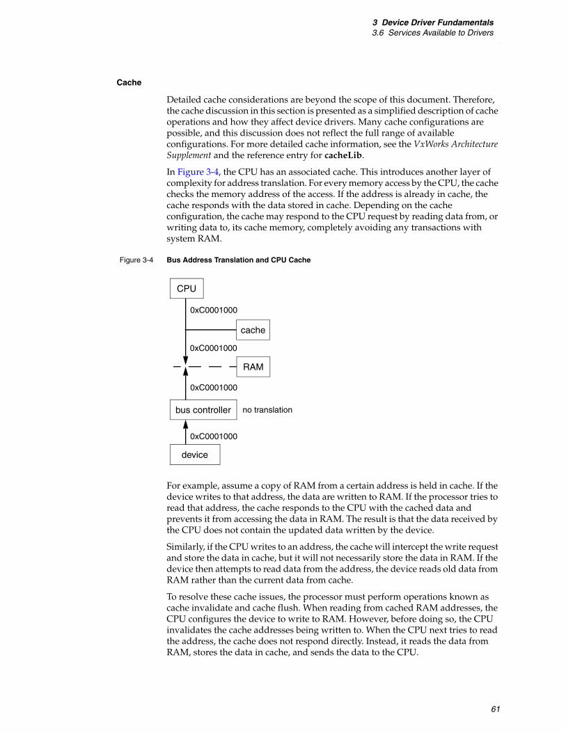
3 Device Driver Fundamentals3.6 Services Available to Drivers
61
Cache
Detailed cache considerations are beyond the scope of this document. Therefore, the cache discussion in this section is presented as a simplified description of cache operations and how they affect device drivers. Many cache configurations are possible, and this discussion does not reflect the full range of available configurations. For more detailed cache information, see the VxWorks Architecture Supplement and the reference entry for cacheLib.
In Figure 3-4, the CPU has an associated cache. This introduces another layer of complexity for address translation. For every memory access by the CPU, the cache checks the memory address of the access. If the address is already in cache, the cache responds with the data stored in cache. Depending on the cache configuration, the cache may respond to the CPU request by reading data from, or writing data to, its cache memory, completely avoiding any transactions with system RAM.
For example, assume a copy of RAM from a certain address is held in cache. If the device writes to that address, the data are written to RAM. If the processor tries to read that address, the cache responds to the CPU with the cached data and prevents it from accessing the data in RAM. The result is that the data received by the CPU does not contain the updated data written by the device.
Similarly, if the CPU writes to an address, the cache will intercept the write request and store the data in cache, but it will not necessarily store the data in RAM. If the device then attempts to read data from the address, the device reads old data from RAM rather than the current data from cache.
To resolve these cache issues, the processor must perform operations known as cache invalidate and cache flush. When reading from cached RAM addresses, the CPU configures the device to write to RAM. However, before doing so, the CPU invalidates the cache addresses being written to. When the CPU next tries to read the address, the cache does not respond directly. Instead, it reads the data from RAM, stores the data in cache, and sends the data to the CPU.
Figure 3-4 Bus Address Translation and CPU Cache
CPU
RAM
bus controller
device
0xC0001000
0xC0001000
no translation
0xC0001000
cache
0xC0001000

VxBusDevice Driver Developer's Guide, 6.9
62
Provided the CPU does not read from the address until after the device writes to it, the operation is performed as expected.
In the second situation, the CPU writes into an address and then notifies the device that the device should read the data there. Before notifying the device to perform the read, the CPU flushes the cache. This instructs the cache to write any pending data from cache into RAM. After this has happened, the device can read the latest information directly from RAM.
Recall that before configuring the device to write into the buffer, the cache invalidate operation is performed, which causes the entire contents of the cache line to be discarded. However, in some cases, it is possible that valid data have been written into the cache line but not written to RAM. In this case, the valid data are discarded along with the invalid cached buffer contents.
To prevent this, driver writers must ensure that all data buffers used for DMA are cache aligned.
Allocating External DMA Engines
Most devices that manipulate large amounts of data have DMA engines included in the device. This allows data to be copied without requiring the CPU to perform the copies, resulting in better overall system performance. However, some devices that manage large amounts of data do not include built-in DMA hardware. VxWorks provides a way for device drivers for such devices to allocate an external DMA engine, also known as a slave DMA engine, if one is available. This allows drivers to eliminate the CPU data copy operations.
This functionality is achieved with vxbDmaLib. The driver calls vxbDmaChanAlloc( ) to allocate a DMA channel, and then calls one of the data copy routines made available when you allocate the channel. There are two variants of the copy. One variant copies the data and waits for the copy operation to complete before returning to the caller, the other variant initiates the copy operation and returns immediately. When the copy is complete, the caller is notified. Both variants are called through function pointers made available when a DMA channel is allocated.
By default, when vxbDmaChanAlloc( ) is called and no DMA engine is available, the routine allocates a software entity that performs the operations using CPU cycles. This allows a driver to request a DMA channel, but use the same interface whether one is available or not. The driver can specify not to use software copy by specifying the DMA_COPY_MODE_NO_SOFT flag.
vxbDmaChanAlloc( )
This routine allocates and initializes a DMA channel for use by a device instance. It searches the system for DMA controller drivers that have dedicated channels, and if found, calls the {vxbDmaResDedicatedGet}( ) method to allocate the dedicated channel. If no dedicated channels are available, this routine searches through the system for any DMA controller drivers that can allocate a channel satisfying the parameters passed to the routine. If a channel is allocated, the routine returns an ID for the channel.
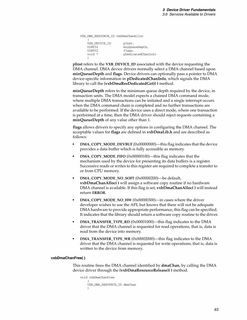
3 Device Driver Fundamentals3.6 Services Available to Drivers
63
VXB_DMA_RESOURCE_ID vxbDmaChanAlloc(VXB_DEVICE_ID pInst,UINT32 minQueueDepth,UINT32 flags,void * pDedicatedChanInfo)
pInst refers to the VXB_DEVICE_ID associated with the device requesting the DMA channel. DMA device drivers normally select a DMA channel based upon minQueueDepth and flags. Device drivers can optionally pass a pointer to DMA device-specific information in pDedicatedChanInfo, which signals the DMA library to call the {vxbDmaResDedicatedGet}( ) method.
minQueueDepth refers to the minimum queue depth required by the device, in transaction units. The DMA model expects a chained DMA command mode, where multiple DMA transactions can be initiated and a single interrupt occurs when the DMA command chain is completed and no further transactions are available to be performed. If the device uses a direct mode, where one transaction is performed at a time, then the DMA driver should reject requests containing a minQueueDepth of any value other than 1.
flags allows drivers to specify any options in configuring the DMA channel. The acceptable values for flags are defined in vxbDmaLib.h and are described as follows:
■ DMA_COPY_MODE_DEVBUF (0x00000000)—this flag indicates that the device provides a data buffer which is fully accessible as memory.
■ DMA_COPY_MODE_FIFO (0x00000100)—this flag indicates that the mechanism used by the device for presenting its data buffers is a register. Successive reads or writes to this register are required to complete a transfer to or from CPU memory.
■ DMA_COPY_MODE_NO_SOFT (0x00000200)—be default, vxbDmaChanAlloc( ) will assign a software copy routine if no hardware DMA channel is available. If this flag is set, vxbDmaChanAlloc( ) will instead return ERROR.
■ DMA_COPY_MODE_NO_HW (0x00000300)—in cases where the driver developer wishes to use the API, but knows that there will not be adequate DMA hardware to provide appropriate performance, this flag can be specified. It indicates that the library should return a software copy routine to the driver.
■ DMA_TRANSFER_TYPE_RD (0x00001000)—this flag indicates to the DMA driver that the DMA channel is requested for read operations, that is, data is read from the device into memory.
■ DMA_TRANSFER_TYPE_WR (0x00002000)—this flag indicates to the DMA driver that the DMA channel is requested for write operations, that is, data is written to the device from memory.
vxbDmaChanFree( )
This routine frees the DMA channel identified by dmaChan, by calling the DMA device driver through the {vxbDmaResourceRelease}( ) method.
void vxbDmaChanFree(VXB_DMA_RESOURCE_ID dmaChan)

VxBusDevice Driver Developer's Guide, 6.9
64
3.6.8 Atomic Operators
Device driver writers often need to update internal data structures to reflect changes in driver state. If they are simultaneously updated by more than one thread of execution, driver data structures can become corrupt. Therefore, you must take specific steps to ensure that corruption does not occur due to contention for the driver data structures.
Traditionally, some type of synchronization primitive is used to ensure that a data structure is updated atomically. Common synchronization primitives include:
■ semaphores
■ spinlocks
■ interrupt locking
In this release, atomic operators have been added to this set of synchronization primitives. As their name implies, atomic operators can be used to atomically modify a data structure. Atomic operators guarantee that their update to a data structure is atomic, even when more than one thread of execution is contending for the shared data structure. In VxWorks, atomic operators are divided into four logical groups:
■ arithmetic
■ logical
■ read/write
■ compare/swap
All the atomic operators act upon a variable of type atomic_t. The atomic_t type is an architecture-dependent integral type, guaranteed to be at least 32 bits in size.
The atomic arithmetic operators are:
atomicVal_t vxAtomicAdd (atomic_t * pTarget, atomicVal_t value); atomicVal_t vxAtomicDec (atomic_t * pTarget); atomicVal_t vxAtomicInc (atomic_t * pTarget); atomicVal_t vxAtomicSub (atomic_t * pTarget, atomicVal_t value);
Each of the arithmetic operators take as input a pointer to a variable of type atomic_t, which is atomically updated by the operator. In all cases, the atomic arithmetic operators return the original value of *pTarget.
The atomic logical operators are:
atomicVal_t vxAtomicAnd (atomic_t * target, atomicVal_t value); atomicVal_t vxAtomicNand (atomic_t * target, atomicVal_t value); atomicVal_t vxAtomicOr (atomic_t * target, atomicVal_t value); atomicVal_t vxAtomicXor (atomic_t * target, atomicVal_t value);
Each of the logical operators take as input a pointer to a variable of type atomic_t, which is atomically updated by the operator. In all cases, the atomic logical operators return the original value of *pTarget.
The atomic read/write operators are:
atomicVal_t vxAtomicClear (atomic_t * target); atomicVal_t vxAtomicGet (atomic_t * target); atomicVal_t vxAtomicSet (atomic_t * target, atomicVal_t value);
Each of the read/write operators take as input a pointer to a variable of type atomic_t, which is atomically updated by the operator. In all cases, the atomic logical operators return the original value of *pTarget.

3 Device Driver Fundamentals3.7 BSP Configuration
65
The atomic compare/swap operator is:
BOOL vxCas (atomic_t * target, atomicVal_t oldValue, atomicVal_t newValue);
The vxCas operator is the most complex of the atomic operators. It is designed to be used to update a data structure by:
■ reading a value from a data structure
■ updating the value, according to the needs of the algorithm
■ writing the value back, but only if the data structure has been left unchanged since the original read from the data structure occurred
vxCas can be useful in cases where a data structure is accessed intermittently, so that it is highly likely that a single thread of execution can read a value from the data structure, modify it, and then write it back, without another thread of execution making a simultaneous attempt to update the structure. This is useful for data structures that have low contention.
If atomic operators are used within a device driver, they must be used consistently. Data elements of type atomic_t should never be directly accessed using simple pointer indirection. The atomic operators perform other operations aside from simple memory operations to ensure that the atomic operations occur as designed. If the atomic operators are not used consistently, correct behavior is not assured.
For further information about the atomic operators, see the reference entry for vxAtomicLib.
3.7 BSP Configuration
One of the goals of the VxBus model is to minimize the need to modify a BSP in order to support new devices. Where BSP support is required, the Vxbus model reduces the effort required to integrate a driver with a new BSP. However, the amount of BSP work required in order for a new driver to work on an existing BSP depends on the type of bus on which the device resides.
If the device resides on a bus such as PCI, which allows the system to probe the device to find out what devices are present and what kind of devices they are, then typically, no BSP modifications are required. In this case, the bus controller finds the devices on the bus and ensures that VxBus knows about them.
For PLB devices, and for other bus types that do not allow the system to discover what devices are present, the system needs some way to determine what devices are present, and to determine the characteristics of those devices. This is normally accomplished by reading an array of devices provided by the BSP.
3.7.1 Requirements for PLB Devices
For PLB-type devices, the BSP typically provides the required array of devices in a table called hcfDeviceList[ ]. This table is usually provided in a hwconf.c file in the BSP. Each entry in hcfDeviceList[ ] contains the name and unit number of a device, the bus type and unit number on which the device resides (which is usually

VxBusDevice Driver Developer's Guide, 6.9
66
VXB_BUSID_PLB unit 0), and a reference to an array of resources associated with the device. For example, the following data structures are typically present in the BSP hwconf.c file in order to incorporate a D1643 timer driver into the BSP, and to configure the timer driver so that it is accessible through the PLB:
const struct hcfResource d16430Resources[] = {/* entries describing resources tailored to the D1643 timer on PLB */
};
const struct hcfDevice hcfDeviceList[] = { {"d1643", 0, VXB_BUSID_PLB, 0, d16430Num, d16430Resources},
};const int hcfDeviceNum = NELEMENTS(hcfDeviceList);
The hcfDevice structure and hcfResource structure are defined in the following file:
installDir/vxworks-6.x/target/h/hwif/vxbus/hwConf.h
There are already many resource names defined in a standardized way as well as a naming convention for resources. When an existing resource name is available for a resource that your driver needs, use the existing resource name. The standard names are as follows:
Device drivers may also require resources that have not been previously named by another driver. In this case, you can assign a name to the resource.
The one required resource is regBase, which is of type HCF_RES_INT. This resource represents the base address of the device registers, or the base address of the first bank of device registers. It must be present and non-zero in order for a device to be associated with a driver. Other regBase entries can optionally exist as well. These entries are identified as regBaseN, where N is a value between 1 and 9. Drivers do not need to read the regBase and regBaseN entries. The system reads those entries and stores the results in the pRegBase[ ] entries in the VXB_DEVICE structure.
When your system is configured with interrupt controller support provided by a VxBus model device driver, interrupt routing information is provided with the interrupt controller driver resources. However, when the BSP provides the code to manage the interrupt controller devices, interrupt information is listed as a resource for each device. In this case, there are two required interrupt resources for each interrupt the device can generate.
Each interrupt requires two resources, an interrupt number and an interrupt level. To ease BSP development, the resources have several aliases. These aliases are:
irq and irqLevelThese aliases can be used to represent the first interrupt that a device generates.
intrN and intrNLevel These aliases can be used to represent multiple interrupts. The character N is replaced either by a decimal number, or it is deleted. For example, valid values can include intr, intr0, intr1, intr2, and so on, along with the corresponding intrLevel, intr0Level, and so on.
regBase intrNLevel rxIntLevelregBaseN txInt errIntLevelirq rxInt regIntervalirqLevel errInt regWidthintrN txIntLevel regDelayclkFreq

3 Device Driver Fundamentals3.7 BSP Configuration
67
txInt, rxInt, and errInt txIntLevel, rxIntLevel, and errIntLevel
These resource names can be used for a device that generates three interrupts for transmit events, receive events, and error events. Note that txInt always refers to interrupt 0, rxInt always refers to interrupt 1, and errInt always refers to interrupt 2.
There are two additional generic resources that are required in some cases and may be used by your driver:
regInterval Describes the amount of space between registers. For example, sometimes a device uses four 8-bit registers, and the board maps the register addresses so that they appear to be located at 32-bit boundaries. In this case, the value of regInterval must be specified as 4.
regWidth Describes the size that must be used to access a register. For example, sometimes a device uses four 8-bit registers, and the board maps the register addresses so that they appear to be located at 32-bit boundaries, and in addition, the device is located on a bus that allows only 32-bit transactions. In this case, the driver needs to access each register with 32-bit transactions or a bus error results. Therefore, the value of regWidth must be specified as 4.
regDelay Describes the delay required between accesses to registers, in milliseconds.
clkFreqDescribes the frequency of an oscillator in Hz.
Resource names should follow the conventions for variable names. For example, if you need to represent a minimum clock rate as a resource, the resource name should be clkRateMin. Where another driver uses a given resource name for a specific kind of information, you should use the same name.
3.7.2 Configuring Device Parameters in the BSP
In addition to resources, each instance can have parameters associated with it. Each parameter has a default value that is provided by the driver, but the BSP can override the value on a per-instance basis. This is done in the parameter table in hwconf.c. The parameter table is terminated by an entry with VXB_PARAM_END_OF_LIST specified as follows:
VXB_INST_PARAM_OVERRIDE sysInstParamTable[] ={...{ NULL, 0, NULL, VXB_PARAM_END_OF_LIST, {(void *)0} }};
Parameters are driver specific. There may be conventions for a given driver class, but many parameters are specific to an individual device. Unlike resources, which have required generic entries for all device classes, there are no generic parameters.
Parameter names should follow the conventions for variable names.

VxBusDevice Driver Developer's Guide, 6.9
68
3.8 SMP Considerations
When writing a device driver, you must decide whether or not the device driver is written to handle the unique challenges presented by symmetric multiprocessing (SMP), or is written to support only a uniprocessor VxWorks system.
If your driver is only planned to run on a uniprocessor system for initial development, you may be tempted to take advantage of the simpler environment that uniprocessor VxWorks presents, and defer any consideration of multiprocessing until the driver is actually required on an SMP platform.
Because the silicon industry is moving inexorably to multicore processors, regardless of vendor, it is difficult to predict what the future requirements will be for any driver. And while it is simpler to write a device driver for a uniprocessor system, you can save yourself a great deal of time in the future by writing a driver to be “SMP-ready” when compared with the cost of retrofitting SMP support into a previously uniprocessor-only driver.
This section describes some of the unique device driver challenges posed by an SMP system, and provides you with some possible solutions to the challenges.
For more information on VxWorks SMP, see the VxWorks Kernel Programmer’s Guide: VxWorks SMP.
3.8.1 Lack of Implicit Locking
As described in Interrupt-Level Synchronization, p.56, the most significant difference between a VxWorks SMP system and a uniprocessor system occurs in the area of mutual exclusion. In a uniprocessor VxWorks system, only one core can execute instructions at any one time, so it is relatively simple to keep track of all of the possible sources of contention. For example:
■ If a driver for a uniprocessor system is executing an ISR, no other task can possibly be competing for the shared resource.
■ If a driver for a uniprocessor system is executing in task context, the driver can lock interrupts in order to prevent any other thread of execution or ISR from gaining control of the CPU, and thus guarantee itself exclusive access to device driver resources.
Given this knowledge, you can construct small areas in the driver where interrupts must be locked, and can guarantee that within these locked regions any driver shared resources cannot be accessed simultaneously by more than one thread of execution.
In a VxWorks SMP system, the simple mutual exclusion model used for a uniprocessor system does not work because multiple cores within the system can execute instructions simultaneously on more than one core. Because of this “true multiprocessing”, your driver must use explicit locking to ensure the driver's shared data structures are protected from corruption by competing threads of execution.
NOTE: VxWorks SMP is an optional product. Depending on what options you have purchased, you may or may not have it available in your installation. The suggestions and issues documented in this section generally apply to SMP systems only.
3 Device Driver Fundamentals3.8 SMP Considerations
69
For details about methods than can be used to protect data structures against simultaneous access on VxWorks SMP systems, see 3.6.6 Synchronization, p.55.
3.8.2 True Task-to-Task Contention
When you write a driver for a uniprocessor VxWorks system, you can ensure only one task is competing for a shared driver resource by judicious use of the taskLock( ) routine. When taskLock( ) is called, the VxWorks scheduler only schedules the task that invoked taskLock( ), regardless of its relative priority when compared with other ready-to-run tasks. The only way in which a task that has called taskLock( ) can be preempted is using an interrupt.
However, in VxWorks SMP, the taskLock( ) routine is not supported. If your device driver uses the taskLock( ) routine, it will not compile correctly for VxWorks SMP. Therefore, instead of using task locking to avoid task-to-task contention, you must again use synchronization methods that are appropriate for VxWorks SMP.
For more information on using synchronization methods to avoid task-to-task contention, see the VxWorks Kernel Programmer’s Guide.
3.8.3 Interrupt Routing
In VxWorks SMP, interrupts from hardware devices can be routed to specific CPUs within the system. At any given time, each hardware interrupt can be routed to at most one CPU in the system. When an interrupt is delivered in an SMP system, the ISR that is attached to the interrupt is executed on the core that the device interrupt is routed to. While this ISR is executing, all task processing is suspended on the core that is handling the interrupt. However, tasks can continue to run on all of the other enabled cores within the system.
Because tasks can run in parallel with ISRs in VxWorks SMP, device drivers that are structured to work correctly in an SMP system must be designed to explicitly protect any data structures that are shared between the ISR and those portions of the driver that run from task context. There are two methods that you can employ to explicitly protect these shared data structures. The methods are:
■ ISR-callable spinlocks
■ ISR deferral of work to a task context
3.8.4 Deferring Interrupt Processing
There are two methods that a device driver can use to protect driver shared resources while a driver is executing in interrupt context. These are:
■ Use a spinlock to protect the shared resource.
■ Defer processing of the interrupt to a specialized deferral task.
In a VxWorks SMP system, you cannot always use a spinlock within an ISR to protect a driver shared resource. For example, this can be because the driver's data structures are part of a protocol stack, and access to the protocol stack is protected using a semaphore. Because your driver cannot take a semaphore within an ISR, the ISR must find another way to manipulate the shared data structures.

VxBusDevice Driver Developer's Guide, 6.9
70
ISRs commonly use a deferral task to modify data that is protected by a semaphore. A deferral task is a dedicated task within VxWorks that pends on a binary semaphore, waiting to be unblocked by an ISR. Within an interrupt service routine, if your driver needs to defer work, you can perform a set of steps to defer the necessary work to task context:
1. Block further interrupt delivery from the hardware. This is necessary because the driver may not be able to clear the interrupt condition from the interrupting device. If your device driver's interrupt service routine returns while the device interrupt is still pending, the pending interrupt is serviced immediately following the ISR return which causes an infinite loop of interrupt processing.
2. Prepare a data buffer that describes the work to be performed. This data buffer needs to be private to the ISR so that it can modify its contents without worrying about contention with other threads of execution.
3. Deliver the data buffer to a waiting deferral task so that the task knows what required work to perform.
4. Unblock the deferral task so that it can then perform the deferred work.
VxWorks provides a utility library to simplify the deferral of interrupt processing. This library, isrDeferLib, is introduced in 3.6.5 Interrupt Handling, p.53. In addition to the services outlined in that section, isrDeferLib provides additional services to support deferred interrupt processing in an SMP environment.
isrDeferLib supports two distinct models of interrupt deferral:
■ individual deferral tasks, dedicated to a specific driver instance
■ shared deferral tasks, which are (potentially) used by more than one driver instance
The choice of deferral model is made when VxWorks is configured. The ISR deferral library (INCLUDE_ISR_DEFER) is typically included in a VxWorks system when a driver that uses the library is included. This is because the driver's use of the deferral library creates a dependency on the deferral library that causes the component to be pulled into the VxWorks system. The deferral library uses its ISR_DEFER_MODE parameter to configure its run-time queue sharing behavior as follows:
■ ISR_DEFER_MODE_PER_CPU—One deferral task is created per CPU that receives deferred interrupts. This deferral task processes all deferred interrupts for a specific CPU within the system.
■ ISR_DEFER_MODE_PER_SOURCE—One deferral task is created for each driver instance that requires a deferral queue.
When device drivers defer interrupts, it is much more efficient to defer interrupts to a task that is running on the same CPU as the CPU where the interrupt is first received. When VxWorks first boots, all interrupts are delivered to CPU 0, but this can be changed at run time by reconfiguring the routing of interrupts through the various interrupt controllers. If an interrupt is migrated from CPU 0 to another CPU in the SMP system, the deferral library must be informed of the change, so that it can adapt to the new interrupt routing. The library uses two methods to adapt to the change in routing:
■ For shared deferral tasks, the ISR deferral library locates a preexisting deferral task (or creates one, if necessary) running on the CPU receiving the rerouted

3 Device Driver Fundamentals3.9 Device Memory Mapping in 64-Bit Devices
71
interrupt. The deferral library returns a handle to this new queue. The driver that receives the new handle should use this handle for all subsequent deferral operations.
■ For individual deferral tasks, the ISR deferral library changes the CPU affinity of the deferral task to correspond to the CPU where the interrupt has been routed. A handle to the deferral task is still returned, but in this situation the handle is unchanged, because no new deferral task is used for interrupt processing.
When an interrupt is rerouted in a running VxWorks system, those device drivers with interrupts that are affected by the reroute, and who publish the {isrRerouteNotify}( ) method, are informed of interrupt reroute events. If your driver uses ISR deferral, publish this driver method so that the driver can be notified of any changes to its interrupt state, and propagate this information to the deferral library. The prototype for {isrRerouteNotify}( ) is:
LOCAL void func{isrRerouteNotify}(VXB_DEVICE_ID pInst, /* instance data for driver */int intIndex, /* index for rerouted interrupt */int destCpu /* destination CPU for rerouted interrupt */)
The body of a driver func{isrRerouteNotify}( ) routine should contain a call to isrDeferIsrReroute( ):
newHandle = isrDeferIsrReroute(pInst->pInstData->dHandle, destCpu); pInst->pInstData->dHandle = newHandle;
For more information, see the reference entry for isrDeferLib.
3.9 Device Memory Mapping in 64-Bit Devices
In 64-bit VxWorks, device memory space is not automatically mapped into the virtual address space by the operating system. Each device driver is individually responsible for mapping the physical address space of the underlying hardware into the virtual address space of the operating system. To accomplish this, device drivers must now use vxbRegMap( ) to create the virtual-to-physical address mapping. This must be performed before any attempt is made by the driver to access the underlying hardware.
All drivers that support memory-mapped I/O must save the size (for the memory-mapped I/O) before executing the vxbRegMap( ) and passing it to the address space allocator.5 Use the regBaseSize[VXB_MAXBARS] array, in the vxbDev structure for the VxBus device instance, to save this size, which is set by the device driver or read from PCI configuration data.
5. The physical base address information is automatically set in the pRegBasePhys[] array.

VxBusDevice Driver Developer's Guide, 6.9
72
The vxbRegMap( ) routine maps the memory-mapped I/O. The BAR is updated by vxbRegMap( ) to the mapped virtual address assigned by address space allocator, and memory-mapped I/O can be accessible through the virtual address. The vxbRegMap( ) routine is called per register base address per VxBus device instance.
If a VxBus driver saves its BARs prior to calling vxbRegMap( ), the order must be changed so that vxbRegMap( ) is executed first, then the BARs are saved, and finally the registers on the BARs are accessed.
For more information about vxbRegMap( ), see the VxWorks API reference entry.
3.10 Physical-to-Virtual Address Translations in 64-Bit VxWorks
When performing a DMA transfer, the hardware (either slave DMA controller or bus-master device) must be programmed with the physical address of the buffer that will be a source or target for the transfer. Traditionally, the CACHE_DRV_VIRT_TO_PHYS( ) and CACHE_DRV_PHYS_TO_VIRT( ) methods in cacheLib have been used in device driver code to perform address translation. There was often (and sometimes still is) a one-to-one relationship between virtual and physical memory address—at least with in the context of the MMU, making address translation in both directions fairly simple and cheap, in terms of performance.
However, physical-to-virtual translations in operating systems with more complex virtual memory systems (such as UNIX), are generally discouraged or, in some cases, are not even supported. Once reason is that a single physical page might be mapped into more than one virtual address. Thus, while translating from a virtual address to a physical address may be straightforward, the inverse is not always true. There are page tables to translate virtual-to-physical, as they are necessary for the MMU to work; but there is no such table for physical-to-virtual translation.
3.10.1 64-bit Changes to the Memory Management Model
In 32-bit VxWorks, the operating system is typically built to run at the bottom of the virtual address space (that is, starting from 0). In this model, physical RAM is usually also mapped at the same location, allowing the virtual and physical address spaces to coincide. However on the Intel architecture, most 64-bit operating systems run near the top of the address space instead, and VxWorks uses the same model. This means that with 64-bit VxWorks, there is never an identity mapping for virtual-to-physical addresses. The exact virtual-to-physical mapping is also not fixed, since it depends upon where the system BIOS has mapped the
NOTE: The port-mapped I/O device on Intel Architecture does not require the size information, since the register access is not a memory-access but an I/O port access. The PCI memory size and the BAR physical address information are automatically received by the vxbPci module from the PCI configuration space, and the PCI device driver does not need to set this information.

3 Device Driver Fundamentals3.10 Physical-to-Virtual Address Translations in 64-Bit VxWorks
73
available physical RAM segments; and this can vary slightly from system to system.
Consequently, performing a physical-to-virtual address translation in 64-bit VxWorks is no longer a simple matter, and might also introduce significant performance penalties. Because of this, CACHE_DRV_PHYS_TO_VIRT( ) and physical-to-virtual address translations in general are not supported in the 64-bit VxWorks environment.
3.10.2 Porting Drivers That Rely on Physical-to-Virtual Address Translations
The majority of device drivers are already designed so that they only need to perform virtual-to-physical translations. As such, they are not affected by the lack of a physical-to-virtual translation mechanism. However, drivers do exist that rely on physical-to-virtual-address translations, and these need to be modified to avoid those translations. While it is generally possible to design a driver that needs only virtual-to-physical translations, some cases are easier than others. Various approaches are described below.
Transfer Using Descriptors
Many devices, particularly network interfaces, perform DMA transfers using descriptors. These can be organized as linked lists or as arrays. The descriptors themselves, in turn, contain the addresses of data buffers that are the sources or destinations of DMA transfers.
When a driver initializes the DMA descriptor ring, it performs virtual-to-physical address translations, in order to ascertain the physical addresses of the descriptors and data buffers. In some cases, drivers have been known to discard the original virtual addresses. At the completion of a DMA transfer, the driver then performs a physical-to-virtual translation in order to recover the virtual address of a data buffer, before handing it off for further processing by the operating system. In general, this method should be avoided, since the physical-to-virtual translation may be costly even when it is possible to do it. In 64-bit VxWorks, this design cannot be used at all. Instead, drivers should cache the virtual addresses of any descriptors or buffers that they might need to reference later.
Linked Lists
In the case of a linked list descriptor ring, each descriptor contains not only a buffer address, but the address of the next descriptor in the ring. Both of these must be physical addresses. When the driver initializes this ring, it needs to perform a virtual-to-physical translation on the address of each descriptor (in order to fill in the next pointers). When processing the ring, it needs the virtual addresses of the descriptors (so that it can traverse the ring) and of the buffers (so that it can hand them off to the operating system for processing). The virtual addresses can be preserved by maintaining a separate, parallel linked list, which is traversed in step with the actual link list used by the hardware. Another approach would be to embed the hardware-defined descriptor structure within a larger driver-defined structure that contains extra fields that the driver software can use for its own reference.

VxBusDevice Driver Developer's Guide, 6.9
74
Descriptor Arrays
Sometimes the hardware requires a descriptor array—meaning that there is no next pointer and that the hardware requires only the address of the first descriptor, then adds an offset to determine the location of the next one. In this case, the driver can maintain a separate array of virtual address information with the same number of entries as the descriptor ring. The driver can then use a single index for both arrays, keeping the virtual and physical descriptor information synchronized.
Strategies When Order is Unpredictable
Note that these strategies depend on being able to predict the order in which the hardware will consume its descriptors. Whether the descriptors are managed as a linked list or an array, the driver always knows the order in which the descriptors will be consumed, and can, thus, easily associate a previously saved virtual address with a physical one. However, in cases in which it is not possible to predict which descriptor will be sourced by the hardware next, a different strategy is required.
Consider the case of a network interface that has multiple ports. The receive path of the interface is designed so that there are three descriptor rings:
■ one buffer ”supply” ring
■ two “return” rings (one for each port)
The driver software is responsible for populating the supply ring descriptors with the addresses of empty buffers. When a packet is received on a given port, the hardware will:
1. Consume one of the supply ring buffers
2. transfer, copy, store or save the packet data into it
3. Fill in a descriptor on its return ring.
This return ring descriptor will contain the address of the buffer that was consumed.
The buffer addresses in the supply and return rings are physical addresses, not virtual addresses. Thus, in order to process the received packet, the driver must recover the virtual address of the buffer. However, there is a problem: the interface has two ports that draw empty buffers from the same shared supply ring; and activity on the ports depends on network load, which will vary unpredictably. If both ports are up and running, and if the supply ring is consumed on a first come, first served basis, there is no way to know the order in which the buffers will be used. This means there is no simple way to determine which supply ring descriptor a given port has consumed. In this scenario, it appears that a physical-to-virtual translation cannot be avoided.
To remove the need for physical-to-virtual translations requires some careful planning. The key is to allocate a contiguous chunk of RAM and have the driver software break it up into chunks, with which it can prime the supply ring. This involves the following steps:
1. Allocate a contiguous chunk of RAM at some virtual base address, Vbase.
2. Perform a virtual to physical translation on Vbase, obtaining physical base address Pbase.
3 Device Driver Fundamentals3.10 Physical-to-Virtual Address Translations in 64-Bit VxWorks
75
3. Store physical buffer offsets (Pbufaddrs) in the supply ring, which will all be offsets relative to Pbase.
4. When the hardware later returns a physical buffer address in one of its return ring descriptors, software can calculate its virtual address using Vbase and Pbase as follows:
relative_bufaddr = Pbufaddr - Pbase
Vbufaddr = relative_bufaddr + Vbase
This operation requires only simple arithmetic, which is fairly cheap in terms of performance. Other schemes involving bit masking can also be used.
This approach can also be used with network acceleration hardware, which provides hardware buffer management. The basic principles can be adapted to other types of devices as well.

VxBusDevice Driver Developer's Guide, 6.9
76

77
4Development Strategies
4.1 Introduction 77
4.2 Writing New VxBus Drivers 77
4.3 VxBus Show Routines 83
4.4 Debugging 94
4.1 Introduction
This chapter outlines development strategies for creating a VxBus model device driver. The chapter presents an overall methodology for creating a new device driver (where no previous VxWorks driver exists). It also presents several suggestions for debugging those aspects of a device driver that are relevant to the interface between the device driver and other modules such as the VxBus core features and middleware.
4.2 Writing New VxBus Drivers
The steps to create a new VxBus driver generally include the following:
1. Create the VxBus infrastructure needed for your driver.
2. Modify your BSP, if necessary.
3. Add debug code based on conditional compilation.
4. Add the VxBus driver methods required by your driver class.
5. Remove all global variables.

VxBusDevice Driver Developer's Guide, 6.9
78
4.2.1 Creating the VxBus Infrastructure
There are several elements required in every VxBus device driver. Start by adding the empty driver framework that interacts with VxBus. The required parts of this framework include the driver source file itself, one or more optional header files, a component description file (CDF) which allows the driver to be visible in Workbench and the vxprj command-line utility, and configuration stub files so that the driver can be included in BSP command-line builds (executed using the make command). (For more information on CDF and configuration stub files, see 3.3.3 Required Files, p.21).
Once all the elements of the driver are present in the correct places, configure the BSP for the development effort.
Writing Driver Source Files
To create the driver source file, start with a template file or an existing driver from the same driver class. Currently, template files are available for network interface (END), PCI bus controller, timer, and serial drivers.
Templates, when available, are kept in the same directory as other drivers of the same class. For example, the template for timer drivers can be found at:
installDir/vxworks-6.x/target/src/hwif/timer/vxbTemplateTimer.c
Writing Header Files (Optional)
Many VxBus device drivers have all source code located in a single source file, with no external header file. However, if your driver includes a number of device-specific macros or other driver-specific information, you can put this information in an optional header file.
Writing the Component Description File (CDF)
The CDF for your driver allows the driver to be configured and included in a project using standard Wind River tools (Workbench and the vxprj command-line utility).
Wind River driver CDF files are located in the following directory:
installDir/vxworks-6.x/target/config/comps/vxWorks
And in the architecture specific directories under this directory. Third-party driver CDF files are located in the following directory:
installDir/vxworks-6.x/target/3rdparty/vendor/driver
By convention, driver files use the prefix 40, for example 40g64120a.cdf.
In most cases, the CDF file for a driver is simple. You must supply a value for Component.
NOTE: This section provides an overview of the component description file requirements for adding a driver. For detailed information, see Component Description File, p.23 and VxWorks Kernel Programmer’s Guide: Kernel.

4 Development Strategies4.2 Writing New VxBus Drivers
79
For example:
Component DRV_CLASS_NAME { NAME DriverName SYNOPSIS Description Of Driver _CHILDREN FOLDER_DRIVERS REQUIRES INCLUDE_VXBUS \
INCLUDE_PLB_BUS \ other requirements
INIT_RTN sampleDriverRegister(); INIT_AFTER INCLUDE_PLB_BUS _INIT_ORDER hardWareInterFaceBusInit _CHILDREN FOLDER_DRIVERS
}
Many drivers have configuration options. For more information on how the driver manages configuration options internally, see VxWorks Kernel Programmer’s Guide. Configuration options that are specified as parameters should be configurable from within Workbench and in vxprj. To do this, provide Parameter entries for each parameter and link the parameters to your Component with the CFG_PARAMS keyword. For more information, see CFG_PARAMS, p.27.
Writing the Configuration Stub Files
Configuration stub files provide similar functionality to the CDF file, but are used when building the VxWorks image from the BSP directory using the make command (this is known as the bspDir/config.h build method).
In most cases, each driver requires two stub files. The stub files are named according to the convention for your driver, with the extensions .dc and .dr.
The driverName.dc file usually contains a forward reference to the driver registration routine, and nothing else. Use the Wind River macro IMPORT to declare this routine. (Note that all registration routines return a void value.)
The following is a sample driver .dc file:
IMPORT void sampleDriverRegister(void);
The .dr file contains a call to the driver registration routine. This call must be surrounded by #ifdef and #endif.
The last line must be terminated with a newline (be sure that your editor does not strip it off).
The following is a sample driver .dr file:
#ifdef DRV_CLASS_NAME sampleDriverRegister();
#endif /* DRV_CLASS_NAME */
Wind River driver .dc and .dr files are located in the following directory:
installDir/vxworks-6.x/target/config/comps/src/hwif
NOTE: In general, you should build your project files using Workbench or the vxprj command-line utility. However, the BSP build method described in this section may be useful in certain development scenarios including early BSP and driver development. For more information on this build method, see the VxWorks Command-Line Tools User’s Guide.

VxBusDevice Driver Developer's Guide, 6.9
80
Third-party driver .dc and .dr files are located in:
installDir/vxworks-6.x/target/3rdparty/vendor/driver
Verifying the Infrastructure
Once you have created your driver, compiled it, added it to a library, and configured your BSP, verify that what you have done so far is correct.
To do this, first build the VxWorks image from the BSP directory. Verify that the driver file is included by using the nmarch command and searching for the registration routine.
Next, verify that the CDF file is correct by starting Workbench and configuring the VxWorks image. If everything is correct, your driver should be available in the drivers folder (not greyed out).
Finally, boot the image and run vxBusShow( ). Your driver should show up in the list of drivers and the target device should show up in the list of devices.
One common problem—frequently encountered when creating drivers for PLB devices—is that the name of the driver does not match the name you provided in the hcfDeviceList[ ] table. When this happens, the output of vxBusShow( ) displays the entry as an orphan rather than a device. If this happens, you must get the driver and device to match up before proceeding.
VxBus matches a driver to its hardware by using strcmp( ) to compare the driver name with the hcfDeviceList[ ] entries. The comparison is case sensitive, and the match must be exact. Check that the driver name and the name listed in the hcfDeviceList[ ] table in hwconf.c are identical and correct as necessary.
The second most common problem at this stage is related to the device's register base address. For PLB devices, the first register base address must be non-null. You can verify this by running vxBusShow( ) with a verbose level argument greater than 1. This displays the full set of pRegBase[ ] entries for each device (instance and orphan) known by VxBus. If the pRegBase[0] entry for your device is zero, correct the problem by supplying the correct base address.
Before moving on to the next step, be sure that your device and driver are connected to each other.
4.2.2 Modifying the BSP (Optional)
Depending on the bus type, VxBus may be able to discover your device automatically. For example, when the device is on a PCI bus or variant of PCI, information about the device is available from PCI configuration space. VxBus
NOTE: In some cases, you may not want to supply the register base address in hwconf.c. In this is the case for your driver, use ERROR or TRUE, both of which are non-null. If you choose this option, your driver must not attempt to read or write registers using the VxBus register access mechanism.
NOTE: Before you start working on your VxBus-enabled driver, you must make sure that your BSP is also VxBus compliant. If your BSP is not enabled for use with VxBus, see the VxWorks BSP Developer’s Guide.

4 Development Strategies4.2 Writing New VxBus Drivers
81
reads this information and compares it against PCI configuration information provided by a driver for a PCI device. If the information matches, the driver is paired with the device.
However, with the PLB bus type, devices are not discovered automatically. In this case, you must add an entry for your device in the hcfDeviceList[ ] array in the BSP hwconf.c file.
For easier debugging, configure your VxWorks Image Project so that the show routines are included. Be sure to include the VxBus show routines in addition to the standard show routines. For example, add the following components:
■ INCLUDE_SHOW_ROUTINES
■ INCLUDE_VXBUS_SHOW
Also include your own driver component:
■ DRV_CLASS_NAME
4.2.3 Adding Debug Code
After the old driver source code is consolidated into a VxBus driver file, you can add additional debug code.
For example, adding debug code is often useful when the driver provides a way to show contents of the driver-specific data area, often referred to as pDrvCtrl.
Most drivers benefit by having debug and other diagnostic information available based on a compile-time macro. If the macro is defined, and a flag is set to the desired debug level, debug code is available at run time.
For most new driver development, you should defer registration of your driver with VxBus. You can manually run your driver registration routine after the system has booted and you are ready to debug your driver. This allows the system to come up without your driver, and you can use the debug facilities from a fully-functional VxWorks image for debugging.
The type of debug information that can be added to a driver is discussed in 4.4 Debugging, p.94.
4.2.4 Adding the VxBus Driver Methods
The next step in your driver development is to find what external interface is used. Typically, this involves finding the VxBus driver methods used by the driver class and then adding the routines that provide the required functionality.
In the early stages of development, you may not want to publish the driver methods. Deferring this step allows you to test the external interface manually without having to worry about whether the middleware or other modules are going to cause undesirable results when the new driver's empty routines are called.
NOTE: When releasing a driver, much of the debug information used during development continues to be valuable. Therefore, leaving the code in the source file can be beneficial in the future, as long as it can be omitted from the object file. For more information on releasing a driver, see 5. Driver Release Procedure.

VxBusDevice Driver Developer's Guide, 6.9
82
Once the functionality used by the required driver methods is available, add the methods to the table of methods in your driver and make sure the table is published in the pMethods field of the VXB_DEVICE_ID.
Note that the general collection of driver-specific method IDs are provided in the following directory:
installDir/vxworks-6.x/target/src/hwif/methods
If your driver requires a new driver method ID (one that does not exist in the general collection of driver-specific method IDs), you can create the new method ID under the above directory.
The following is an example of the busCtlrAccessOverride method ID given in the following directory:
installDir/vxworks-6.x/target/src/hwif/methods
To build the new method ID object file and archive it into a library, you must create a .c file that contains the definition of the driver method ID and a .mk file that can be included by the following makefile:
installDir/vxworks-6.x/target/src/hwif/methods/Makefile
The busCtlrAccessOverride.c is as follows:
#include <vxWorks.h>#include <vxBusLib.h>#include <hwif/vxbus/vxBus.h>
DEVMETHOD_DEF(busCtlrAccessOverride, "busCtlrAccessOverride");
The busCtlrAccessOverride.mk is as follows:
OBJS_COMMON += busCtlrAccessOverride.o
4.2.5 Removing Global Variables
One of the important goals of a generic driver is that it support multiple devices of the same type. Earlier in the development process, you may have chosen to create global variables specific to an instance (that is, a given device and driver paired together). These global variables should be removed.
In VxBus, the main identification of a device is the VXB_DEVICE_ID. The structure VXB_DEVICE_ID points to has a field for pDrvCtrl. pDrvCtrl is owned by the driver and can be used for any purpose. Most drivers define a structure containing all instance-specific information.
During initialization, this structure is allocated using hwMemAlloc( ), filled in with the data, and a pointer to the structure is saved in the pDrvCtrl field. Later, when the driver is called for any reason, the VXB_DEVICE_ID is passed as a parameter, from which the driver can extract the pDrvCtrl field to get access to the instance-specific data.
In many cases, it is necessary to rewrite the prototype of some routines to pass the pDrvCtrl or VXB_DEVICE_ID as a parameter.
NOTE: In this step, you are expected to create the actual device management code which is a time-consuming step in the device driver development process.

4 Development Strategies4.3 VxBus Show Routines
83
4.3 VxBus Show Routines
There are a number of show routines available for use with VxBus. This section describes some of the show routines, demonstrates how they can be used to assist driver development, and explains how to configure them into the system.
4.3.1 Available Show Routines
This section lists and describes the available VxBus show routines.
vxBusShow( )
The most basic show routine in the VxBus framework is vxBusShow( ). This routine provides a list of information related to drivers and devices.
There are several levels of detail available when using this routine. The level of detail is specified by the value of the argument. A value of 0 provides the following basic information:
■ bus types that are available on the system
■ drivers that are registered, and the bus types they use
■ buses that are present on the system
■ devices that are present on each bus
■ whether each device has been paired with a driver
Example 4-1 shows the output for a typical vxBusShow( ) routine run on a Pentium target.
Example 4-1 Basic vxBusShow( ) Output
-> vxBusShow() Registered Bus Types: MII_Bus @ 0x004531d4 PCI_Bus @ 0x0044fbcc Local_Bus @ 0x0044f98c
Registered Device Drivers:yn at 0x00452ef8 on bus PCI_Bus, funcs @ 0x00452e18fei at 0x00452d98 on bus PCI_Bus, funcs @ 0x00452c68geiHEnd at 0x004530c4 on bus PCI_Bus, funcs @ 0x004530a8genericPhy at 0x0045322c on bus MII_Bus, funcs @ 0x00453220miiBus at 0x0045318c on bus PCI_Bus, funcs @ 0x0045312cmiiBus at 0x00453148 on bus Local_Bus, funcs @ 0x0045312cns16550 at 0x0044f4e4 on bus Local_Bus, funcs @ 0x0044f474ns16550 at 0x0044f49c on bus PCI_Bus, funcs @ 0x0044f474pentiumPci at 0x0044fbf4 on bus Local_Bus, funcs @ 0x0044fbe8plbCtlr at 0x0044f9b4 on bus Local_Bus, funcs @ 0x0044f9a8
Busses and Devices Present:Local_Bus @ 0x00466790 with bridge @ 0x0044f9f4Device Instances:
pentiumPci unit 0 on Local_Bus @ 0x00467a50 with busInfo 0x004669d0ns16550 unit 1 on Local_Bus @ 0x004678d0 with busInfo 0x00000000ns16550 unit 0 on Local_Bus @ 0x00467750 with busInfo 0x00000000
Orphan Devices:i8042Mse unit 0 on Local_Bus @ 0x00469350 with busInfo 0x00000000i8042Kbd unit 0 on Local_Bus @ 0x00469250 with busInfo 0x00000000
PCI_Bus @ 0x004669d0 with bridge @ 0x00467a50

VxBusDevice Driver Developer's Guide, 6.9
84
Device Instances:miiBus unit 1 on PCI_Bus @ 0x004747d0 with busInfo 0x0046be10miiBus unit 0 on PCI_Bus @ 0x00469450 with busInfo 0x00469cd0fei unit 0 on PCI_Bus @ 0x00468e50 with busInfo 0x00000000ns16550 unit 3 on PCI_Bus @ 0x00468c50 with busInfo 0x00000000yn unit 0 on PCI_Bus @ 0x00468350 with busInfo 0x00000000geiHEnd unit 0 on PCI_Bus @ 0x00467e50 with busInfo 0x00000000
Orphan Devices:(null) unit 0 on PCI_Bus @ 0x00469150 with busInfo 0x00000000(null) unit 0 on PCI_Bus @ 0x00469050 with busInfo 0x00000000(null) unit 0 on PCI_Bus @ 0x00468f50 with busInfo 0x00000000(null) unit 0 on PCI_Bus @ 0x00468b50 with busInfo 0x00000000(null) unit 0 on PCI_Bus @ 0x00468a50 with busInfo 0x00000000(null) unit 0 on PCI_Bus @ 0x00468950 with busInfo 0x00000000(null) unit 0 on PCI_Bus @ 0x00468850 with busInfo 0x00000000(null) unit 0 on PCI_Bus @ 0x00468750 with busInfo 0x00000000(null) unit 0 on PCI_Bus @ 0x00468650 with busInfo 0x00000000(null) unit 0 on PCI_Bus @ 0x00468550 with busInfo 0x00000000(null) unit 0 on PCI_Bus @ 0x00468450 with busInfo 0x00000000(null) unit 0 on PCI_Bus @ 0x00468250 with busInfo 0x00000000(null) unit 0 on PCI_Bus @ 0x00468150 with busInfo 0x00000000(null) unit 0 on PCI_Bus @ 0x00468050 with busInfo 0x00000000(null) unit 0 on PCI_Bus @ 0x00467f50 with busInfo 0x00000000(null) unit 0 on PCI_Bus @ 0x00467d50 with busInfo 0x00000000(null) unit 0 on PCI_Bus @ 0x00467c50 with busInfo 0x00000000(null) unit 0 on PCI_Bus @ 0x00467b50 with busInfo 0x00000000
MII_Bus @ 0x0046be10 with bridge @ 0x004747d0Device Instances:
genericPhy unit 0 on MII_Bus @ 0x00474850 with busInfo 0x00000000Orphan Devices:
MII_Bus @ 0x00469cd0 with bridge @ 0x00469450Device Instances:
genericPhy unit 0 on MII_Bus @ 0x004694d0 with busInfo 0x00000000Orphan Devices:
Many VxBus routines require that the VxBus device ID be provided as an argument. The most commonly used part of the vxBusShow( ) output is the device ID for individual devices. The device ID is the field after the bus type, indicated with the @ symbol. For example, the device ID of the mouse device, i8042Mse, is 0x00469350, as shown in:
i8042Mse unit 0 on Local_Bus @ 0x00469350 with busInfo 0x00000000
Higher verbose level values result in the display of additional information. Each driver can publish a show routine that is integrated into vxBusShow( ) (see 4.4.1 Configuring Show Routines, p.94). The amount and format of the information that is displayed depends on the driver and the information that the driver chooses to display based upon a given verbose level.
For all devices, vxBusShow(1) displays non-null values of pRegBase[ ], in addition to the information displayed at verbose level 0.
When the verbose level is greater than 1000, vxBusShow( ) displays all values of pRegBase[ ], even if they are NULL. Because the output with non-zero verbose levels is long, the following examples show only an excerpt of the outputs.
NOTE: The remainder of this section discusses only the generic format used when the driver does not publish a show routine.
NOTE: The following examples are displayed from a different system than shown in Example 4-1.

4 Development Strategies4.3 VxBus Show Routines
85
Example 4-2 vxBusShow( ) Verbose Output
-> vxBusShow(1) ...
iaTimestamp unit 0 on Local_Bus @ 0x0042ff48 with busInfo 0x00000000pDrvCtrl @ 0x00430048
fileNvRam unit 0 on Local_Bus @ 0x00430148 with busInfo 0x00000000BAR0 @ 0xffffffff (IO space)pDrvCtrl @ 0x0042cb48
Orphan Devices:PCI_Bus @ 0x0042bec8 with bridge @ 0x0042d048Device Instances:
fei unit 0 on PCI_Bus @ 0x0042d848 with busInfo 0x00000000BAR0 @ 0xfc9bf000 (memory mapped)BAR1 @ 0x0000bc00 (IO space)BAR2 @ 0xfc800000 (memory mapped)pDrvCtrl @ 0x04419284
... (null) unit 0 on PCI_Bus @ 0x0042d648 with busInfo 0x00000000
BAR2 @ 0x00030300 (memory mapped)BAR3 @ 0x200000f0 (memory mapped)BAR4 @ 0x0000fff0 (memory mapped)BAR5 @ 0x0001fff0 (IO space)pDrvCtrl @ 0x00000000
...
-> vxBusShow(1001) ...PCI_Bus @ 0x0042bec8 with bridge @ 0x0042d048Device Instances:
fei unit 0 on PCI_Bus @ 0x0042d848 with busInfo 0x00000000BAR0 @ 0xfc9bf000 (memory mapped)BAR1 @ 0x0000bc00 (IO space)BAR2 @ 0xfc800000 (memory mapped)BAR3 @ 0x00000000 (none)BAR4 @ 0x00000000 (none)BAR5 @ 0x00000000 (none)BAR6 @ 0x00000000 (none)BAR7 @ 0x00000000 (none)BAR8 @ 0x00000000 (none)BAR9 @ 0x00000000 (none)pDrvCtrl @ 0x04419284
...
vxbDevStructShow( )
The prototype for vxbDevStructShow( ) is as follows:
STATUS vxbDevStructShow(VXB_DEVICE_ID devID)
The vxbDevStructShow( ) routine displays the fields of the device structure. When developing bus controller and multifunction drivers, this routine is often useful to display the information contained in the child devices created by the bus controller driver or multifunction driver. For general driver development, this routine is used to find the characteristics of a given device, such as pRegBase[ ] values. For example:
-> fei0 = 0x00468350
-> vxbDevStructShow(fei0) vxbDev fei @ 0x00468350
pNext -> 0x00468c50pParentBus -> 0x004669d0pMethods @ 0x00000000pAccess @ 0x0042e0c8pRegBase[0] @ 0xfc9bf000pRegBase[1] @ 0x0000bc00pRegBase[2] @ 0xfc800000

VxBusDevice Driver Developer's Guide, 6.9
86
pRegBase[3] @ 0x00000000pRegBase[4] @ 0x00000000pRegBase[5] @ 0x00000000pRegBase[6] @ 0x00000000pRegBase[7] @ 0x00000000pRegBase[8] @ 0x00000000pRegBase[9] @ 0x00000000pSubordinateBus @ 0x00000000pBusSpecificDevInfo @ 0x0042c348busID = PCI_Bus (3)pIntrInfo @ 0x0042c908pDriver @ 0x0041f7dcpDrvCtrl @ 0x04419430u.pDevPrivate @ 0x00000000
vxbDevPathShow( )
The prototype for vxbDevPathShow( ) is as follows:
void vxbDevPathShow(VXB_DEVICE_ID devID)
The vxbDevPathShow( ) routine indicates the bus controllers upstream from the specified device to the PLB. For example:
-> sio3 = 0x00468c50
-> vxbDevPathShow(sio3) device ns16550 @ 0x00468c50device pentiumPci @ 0x00467a50device plbCtlr @ 0x0044f9f4
4.3.2 PCI Show Routines
The PCI show routines available in VxWorks prior to the introduction of the VxBus driver infrastructure are still available in this release. However, the older PCI show routines may not always work exactly as expected. In VxWorks 6.6, the PCI configuration was enhanced to support logically separate PCI buses. That is, a single system can have two or more PCI buses that are not related to each other in any way. When this occurs, there are two primary implications for the device driver developer.
First, there is a default PCI bus, and any given device may not be reachable from the default bus. The older PCI show routines use only the default bus, therefore if the device you are looking for is not present on the default bus, it is not listed by the older show routines.
The next consideration is that the [bus,device,function] triple no longer uniquely identifies a single device. This means that older PCI show routines cannot be used.
Many of the older PCI show routines have corresponding show routines specific to VxBus. In general, the first argument to a new routine is the VxBus device ID of the bus controller immediately upstream from the device. The VxBus routines are discussed in the following sections.
NOTE: When pRegBase[0] is NULL on PLB devices, the device is not matched with a driver, but instead remains an orphan.

4 Development Strategies4.3 VxBus Show Routines
87
pciDevShow( )
The prototype for pciDevShow( ) is as follows:
void pciDevShow(VXB_DEVICE_ID devID)
The pciDevShow( ) routine displays PCI information about the specified device. This includes the [bus,device,function] triple, and the device ID and vendor ID, that were read from PCI configuration space when the device was created. For example:
-> yn0 = 0x00468350
-> pciDevShow(yn0) pDev @ 0x00468350 [3,0,0]
devID = 0x4b00vendID = 0x1186
The devID and vendID fields shown by pciDevShow( ) are used when matching PCI devices and drivers. If the information displayed by pciDevShow( ) does not match the values listed in your driver, you may need to modify your driver to get an exact match.
vxbPciDeviceShow( )
The prototype for vxbPciDeviceShow( ) is as follows:
STATUS vxbPciDeviceShow(VXB_DEVICE_ID busCtrlID,int busNo)
The vxbPciDeviceShow( ) routine displays information about devices found on the PCI bus downstream of the specified PCI bus controller device. Only information about the PCI bus numbered busNo is listed.
-> pentiumPci = 0x0044fbf4
-> vxbPciDeviceShow(pentiumPci,0) Scanning functions of each PCI device on bus 0 Using configuration mechanism 1bus device function vendorID deviceID class/rev
0 0 0 0x8086 0x3590 0x0600000c0 2 0 0x8086 0x3595 0x0604000c0 4 0 0x8086 0x3597 0x0604000c0 6 0 0x8086 0x3599 0x0604000c0 28 0 0x8086 0x25ae 0x060400020 30 0 0x8086 0x244e 0x0604000a0 31 0 0x8086 0x25a1 0x060100020 31 1 0x8086 0x25a2 0x01018a020 31 3 0x8086 0x25a4 0x0c050002
NOTE: The following output is displayed from a different system than the vxBusShow( ) output in vxBusShow( ), p.83.

VxBusDevice Driver Developer's Guide, 6.9
88
vxbPciHeaderShow( )
The prototype for vxbPciHeaderShow( ) is as follows:
STATUS vxbPciHeaderShow(VXB_DEVICE_ID busCtrlID,int busNo, /* bus number */int deviceNo, /* device number */int funcNo /* function number */)
The vxbPciHeaderShow( ) routine displays the full contents of the PCI header for an individual device. Note that the device is specified by four values: the bus controller device, and the PCI triple [bus,device,function]. This means that vxbPciHeaderShow( ) is usable even when the BSP excludes a particular device from being configured. (For information about excluding a particular device within the BSP, see the reference entry for vxbPciAutoConfig( ).)
The following sample shows the PCI header for the Yukon II network interface device. Notice that the VxBus device ID for the yn0 device is not used as an argument to vxbPciHeaderShow( ). Instead, use the [bus,device,function] triple as provided in the output of pciDevShow( ).
-> yn0 = 0x00468350
-> pciDevShow(yn0) pDev @ 0x00468350 [3,0,0]
devID = 0x4b00vendID = 0x1186
-> pciCtlr = 0x004669d0
-> vxbPciHeaderShow pciCtlr,3,0,0 vendor ID = 0x1186device ID = 0x4b00command register = 0x0007status register = 0x4010revision ID = 0x11class code = 0x02sub class code = 0x00programming interface = 0x00cache line = 0x08latency time = 0x00header type = 0x00BIST = 0x00base address 0 = 0xfe3fc004base address 1 = 0x00000000base address 2 = 0x0000b801base address 3 = 0x00000000base address 4 = 0x00000000base address 5 = 0x00000000cardBus CIS pointer = 0x00000000sub system vendor ID = 0x1186sub system ID = 0x4b00expansion ROM base address = 0xfe3c0000interrupt line = 0x0binterrupt pin = 0x01min Grant = 0x00max Latency = 0x00Capabilities - Power ManagementCapabilities - Vital Product DataCapabilities - Message Signaled Interrupts: Disabled, 64-bit, MMC: 0 MME: 1
Address: 0082e0050082e005 Data: 0xe005 Capabilities - PCIe: Legacy Endpoint, IRQ 0
Device: Max Payload: 128 bytes, Extended Tag: 5-bitAcceptable Latency: L0 - >4us, L1 - >64usErrors Enabled: AUX Pwr PMMax Read Request 512 bytes

4 Development Strategies4.3 VxBus Show Routines
89
Link: MAX Speed - 2.5Gb/s, MAX Width - by 1 Port - 0 ASPM - L0sLatency: L0s - <256ns, L1 - >64usASPM - Disabled, RCB - 128bytesSpeed - 2.5Gb/s, Width - by 1
vxbPciFindDeviceShow( )
The prototype for vxbPciFindDeviceShow( ) is as follows:
STATUS vxbPciFindDeviceShow(VXB_DEVICE_ID busCtrlID,int vendorId, /* vendor ID */int deviceId, /* device ID */int index /* desired instance of device */)
The vxbPciFindDeviceShow( ) routine scans the PCI bus identified by busCtlrID, searching for devices on the bus with the requested vendor and device ID. Because multiple devices with the same vendor and device ID can be present on a single PCI bus, you can provide an index parameter to identify which occurrence of the device to display information for. For example, in the following sample output, vxbPciFindDeviceShow( ) searches for the first occurrence of a device with vendor ID 0x1186 and device ID 0x4b00:
-> pentiumPci = 0x0044fbf4
-> vxbPciFindDeviceShow(pentiumPci, 0x1186, 0x4b00, 0) deviceId = 0x4b00vendorId = 0x1186index = 0busNo = 3deviceNo = 0funcNo = 0
vxbPciFindClassShow( )
The prototype for vxbPciFindClassShow( ) is as follows:
STATUS vxbPciFindClassShow (VXB_DEVICE_ID busCtrlID,int classCode, /* 24-bit class code */int index /* desired instance of device */)
The vxbPciFindClassShow( ) routines scans the PCI bus identified by busCtlrID, searching for devices on the bus with the requested class code. Because multiple devices with the same class code can be present on a single PCI bus, you can provide an index parameter to identify which occurrence of the device to display information for. For example, in the following sample output, vxbPciFindClassShow( ) searches for the first occurrence of a device with class code 0x002:
-> pentiumPci = 0x0044fbf4
-> vxbPciFindClassShow(pentiumPci, 0x02, 0) class code = 0x2index = 0x0busNo = 0x3deviceNo = 0x0funcNo = 0x0

VxBusDevice Driver Developer's Guide, 6.9
90
vxbPciConfigTopoShow( )
The prototype for vxbPciConfigTopoShow( ) is as follows:
void vxbPciConfigTopoShow(VXB_DEVICE_ID busCtrlID)
The vxbPciConfigTopoShow( ) routine displays information about PCI devices in a relatively easy-to-use format.
-> pentiumPci = 0x0044fbf4
-> vxbPciConfigTopoShow(pentiumPci) [0,2,0] type=P2P BRIDGE to [1,0,0]
base/limit:mem= 0xfff00000/0x000fffffpreMem=0x00000000fff00000/0x00000000000fffffI/O= 0xf000/0x0fff
status=0x4018 ( CAP DEVSEL=0 ASSERT_SERR )command=0x0007 ( IO_ENABLE MEM_ENABLE MASTER_ENABLE ) [0,4,0] type=P2P
BRIDGE to [2,0,0]base/limit:mem= 0xfff00000/0x000fffffpreMem=0x00000000fff00000/0x00000000000fffffI/O= 0xf000/0x0fff
status=0x4018 ( CAP DEVSEL=0 ASSERT_SERR )command=0x0007 ( IO_ENABLE MEM_ENABLE MASTER_ENABLE ) [0,6,0] type=P2P
BRIDGE to [3,0,0]base/limit:mem= 0xfff00000/0x000fffffpreMem=0x00000000fff00000/0x00000000000fffffI/O= 0xf000/0x0fff
status=0x4018 ( CAP DEVSEL=0 ASSERT_SERR )command=0x0007 ( IO_ENABLE MEM_ENABLE MASTER_ENABLE ) [0,28,0] type=P2P
BRIDGE to [4,0,0]base/limit:mem= 0xfc500000/0xfc9fffffpreMem=0x00000000fff00000/0x00000000000fffffI/O= 0xb000/0xbfff
status=0x0030 ( CAP 66MHZ DEVSEL=0 )command=0x0007 ( IO_ENABLE MEM_ENABLE MASTER_ENABLE ) [4,2,0]
type=NET_CNTLRstatus=0x0290 ( CAP FBTB DEVSEL=1 )command=0x0007 ( IO_ENABLE MEM_ENABLE MASTER_ENABLE )bar0 in 32-bit mem space @ 0xfc9bf000bar1 in I/O space @ 0x0000bc00bar2 in 32-bit mem space @ 0xfc800000 [0,30,0] type=P2P BRIDGE to
[5,0,0]base/limit:mem= 0xfca00000/0xfeafffffpreMem=0xfff00000/0x000fffffI/O= 0xc000/0xcfff
status=0x0080 ( FBTB DEVSEL=0 )command=0x0007 ( IO_ENABLE MEM_ENABLE MASTER_ENABLE ) [5,1,0]
NOTE: For Intel x86-based targets, the address and data registers for accessing PCI configuration space are located at 0xcf8 and 0xcfc in I/O space, and, by convention, there is just the one set. There may be more than one PCI host bridge connected to the CPU, but the chipset implements a mapping scheme that makes the PCI devices appear as though they are all part of a single device tree with a common root.
NOTE: The following output is displayed from a different system than the vxBusShow( ) output in vxBusShow( ), p.83.

4 Development Strategies4.3 VxBus Show Routines
91
type=DISP_CNTLRstatus=0x0290 ( CAP FBTB DEVSEL=1 )command=0x0087 ( IO_ENABLE MEM_ENABLE MASTER_ENABLE WC_ENABLE )bar0 in 32-bit mem space @ 0xfd000000bar1 in I/O space @ 0x0000c800bar2 in 32-bit mem space @ 0xfeaff000 [0,31,0] type=ISA BRIDGEstatus=0x0280 ( FBTB DEVSEL=1 )command=0x000f ( IO_ENABLE MEM_ENABLE MASTER_ENABLE MON_ENABLE )
[0,31,1] type=MASS STORAGEstatus=0x0288 ( FBTB DEVSEL=1 )command=0x0007 ( IO_ENABLE MEM_ENABLE MASTER_ENABLE )bar0 in I/O space @ 0x000001f0bar1 in I/O space @ 0x000003f4bar2 in I/O space @ 0x00000170bar3 in I/O space @ 0x00000374bar4 in I/O space @ 0x0000fc00
[0,31,3] type=SERIAL BUSstatus=0x0280 ( FBTB DEVSEL=1 )command=0x0001 ( IO_ENABLE )bar4 in I/O space @ 0x00000540
4.3.3 Using Show Routines from Software
This section describes how software can use certain VxBus services, including how to find a VxBus device ID given suitable identification information.
One bit of information that is not provided directly by vxBusShow( ) is the bus-specific information for orphan devices. For example, the vxBusShow( ) output for an orphan PCI device is as follows:
(null) unit 0 on PCI_Bus @ 0x00468a50 with busInfo 0x00000000
Obviously, this is not enough information to know much about the device.
Ideally, when debugging a driver for PCI devices, you should know the [bus,device,function] triplet. You can get this by providing a routine that prints information about the devices it sees and then using vxbDevIterate( ) to call the routine for every device. For example, you could provide the following routine:
STATUS pciShowHelper(VXB_DEVICE_ID devID,void * pArg){struct vxbPciDevice * pPci;
if ( devID->busID != VXB_BUSID_PCI )/* wrong bus type, just return */return(OK);
pPci = (struct vxbPciDevice *)devID->pBusSpecificDevInfo;
if ( devID->pName == NULL )printf("PCI device orphan 0x%08x devID 0x%04x vendID 0x%04x at
[%d,%d,%d]\n",devID, pPci->pciDevId, pPci->pciVendId,pPci->pciBus, pPci->pciDev, pPci->pciFunc);
else printf("PCI device %s%d devID 0x%04x vendID 0x%04x at [%d,%d,%d]\n",
devID->pName, devID->unitNumber,pPci->pciDevId, pPci->pciVendId,pPci->pciBus, pPci->pciDev, pPci->pciFunc);
return(OK);}

VxBusDevice Driver Developer's Guide, 6.9
92
Then, use this routine with vxbDevIterate( ). When using vxbDevIterate( ), you can indicate that the routine should only be run on orphan devices by specifying the value 2 as the third argument.
-> vxbDevIterate(pciShowHelper,0,2) PCI device orphan 0x0042d348 devID 0x3590 vendID 0x8086 at [0,0,0] PCI device orphan 0x0042d448 devID 0x3595 vendID 0x8086 at [0,2,0] PCI device orphan 0x0042d548 devID 0x3597 vendID 0x8086 at [0,4,0] PCI device orphan 0x0042d648 devID 0x3599 vendID 0x8086 at [0,6,0] PCI device orphan 0x0042d748 devID 0x25ae vendID 0x8086 at [0,28,0] PCI device orphan 0x0042d948 devID 0x244e vendID 0x8086 at [0,30,0] PCI device orphan 0x0042da48 devID 0x4c52 vendID 0x1002 at [5,1,0] PCI device orphan 0x0042db48 devID 0x25a1 vendID 0x8086 at [0,31,0] PCI device orphan 0x0042fc48 devID 0x25a2 vendID 0x8086 at [0,31,1] PCI device orphan 0x0042fd48 devID 0x25a4 vendID 0x8086 at [0,31,3]
It is possible to use the show routines from test code or other software. However, to do this, your code needs to find the VxBus device ID of the desired device. This can be accomplished by requiring the user to provide the VxBus device ID. However, it may be more convenient to provide the driver name and unit number.
struct devNameAndUnit{VXB_DEVICE_ID devID;char * devName;int devUnit;};
STATUS pciDevByNameUnitHelper(VXB_DEVICE_ID devID,struct devNameAndUnit * pDev){struct vxbPciDevice * pPci;
if ( pDev->devID != NULL )/* already found, just return */return(OK);
if ( ( strcmp(devID->pName,pDev->devName) == 0 ) &&( devID->unitNumber == pDev->devUnit ) )/* found it */pDev->devID = devID;
return(OK);}
VXB_DEVICE_ID pciDevByNameUnitFind(char * devName, int devUnit){struct devNameAndUnit nmUnit;
nmUnit.devID = NULL;nmUnit.devName = devName;nmUnit.devUnit = devUnit;
vxbDevIterate(pciDevByNameUnitHelper, &nmUnit, 1)
return(nmUnit.devID);}
The pciDevByNameUnitFind( ) routine can be used within the code to find the VxBus device ID of the desired device.
-> pciDevByNameUnitFind("fei",0) value = 4623952 = 0x00468e50
NOTE: The following output is displayed from a different system than other output examples in this section.

4 Development Strategies4.3 VxBus Show Routines
93
4.3.4 Configuring Show Routines into VxWorks
This section describes how to include the necessary components for VxBus show routines in your VxWorks image.
Configuring Generic VxBus Show Routines
To include the generic Vxbus show routines, include the following macros or components when building your VxWorks image:
■ INCLUDE_SHOW_ROUTINES
■ INCLUDE_PCI_BUS_SHOW
■ INCLUDE_VXBUS_SHOW
Configuring Interrupt Show Routines
If you are concerned with interrupt routing information, additional information may be available from the interrupt controller driver. This information is more difficult to configure, due to the fact that interrupt controller drivers and the interrupt controller driver support library are compiled outside the context of a project or BSP.
Several source files need to be recompiled and archived into the driver library. The files are all located in the following directory:
installDir/vxworks-6.x/target/src/hwif/intCtlr
The interrupt controller driver support library provides show routines when the INTCTLR_LIB_SHOW macro is defined. Individual interrupt controller drivers are configured with additional show routines by defining driver-specific macros.
To determine which macros you need to define, you must determine which interrupt controller driver is included with your system, and check for preprocessor macros containing any of the following strings:
■ _DEBUG_
■ _DBG_
■ _SHOW
For example, if the EPIC interrupt controller driver, vxbEpicIntCtlr.c is used, the macro VXB_EPICINTCTLR_DBG_ON determines whether debug information is included.
Once you have determined which macros need to be defined, run a make command to build the files, specifying ADDED_CFLAGS to define the macros. You must also specify the appropriate CPU and TOOL values for your hardware.
For example:
% make CPU=PPC32 TOOL=diab \ADDED_CFLAGS="-DVXB_EPICINTCTLR_DBG_ON -DINTCTLR_LIB_SHOW"
The names and parameters that are required by the interrupt controller driver show routines are driver-dependent.
NOTE: You may need to update the timestamp on the files in order to build the object modules. Also, be sure to restore the non-debug versions of these files before creating your final release code.

VxBusDevice Driver Developer's Guide, 6.9
94
4.4 Debugging
This section provides general information on debugging VxBus device drivers. In addition to the information in this section, you should also review any class-specific debugging hints which are provided in the class-specific chapters of Part II.
The general debugging hints discussed in this section include:
■ Configuring the vxBusShow( ) routine. (4.4.1 Configuring Show Routines, p.94)
■ Deferring driver registration. (4.4.2 Deferring Driver Registration, p.95)
■ Including debug code in the driver. (4.4.3 Including Debug Code, p.95)
■ Confirming register access. (4.4.4 Confirming Register Access, p.96)
■ Adjusting the size of HWMEM_POOL. (4.4.5 Increasing the Size of HWMEM_POOL, p.96)
■ Confirming the driver and device names match for PLB devices. (4.4.6 Confirming Device and Driver Name Matches, p.96)
4.4.1 Configuring Show Routines
When debugging, you may want to integrate a show routine into your driver with the VxBus show module. This is done by advertising the {busDevShow}( ) driver method. The func{busDevShow}( ) routine must have the following prototype:
STATUS sampleDriverpDrvCtrlShow (VXBUS_DEVICE_ID devID,int verboseLevel)
When verboseLevel is zero, the func{busDevShow}( ) routine prints the name, unit number, and device ID in a manner similar to that displayed for the vxBusShow( ) output for other devices.
When verboseLevel is non-zero, additional information is displayed. The information displayed varies depending on the specific needs of your driver. Larger verboseLevel values produce a wider range of information.
Table 4-1 lists recommended values for verboseLevel.
Table 4-1 Recommended Values for verboseLevel
Level Description
0 Print only the driver name and unit, VXB_DEVICE_ID, and bus type.
1 Print level 0 information, plus non-null pRegBase[ ] values.
2 Print level 1 information, plus all pRegBase[ ] values.
3 ... 8 Reserved, print only level 0 information.

4 Development Strategies4.4 Debugging
95
4.4.2 Deferring Driver Registration
Another simple debug modification is to defer the driver registration with VxBus. When registration is deferred, VxBus is unaware of the driver at boot time. For debugging purposes, you register the driver from the VxWorks shell (either the host shell or the target shell). When VxBus finds that a new driver is available, it searches the list of orphan devices (devices not associated with a driver) for any device that matches the new driver. If it finds one, it pairs the driver with the device and runs through the normal initialization sequence.
For some driver classes, additional work may need to be done in order for the device to be fully recognized by the available middleware modules. This is explained further in the class-specific chapters in Part II.
4.4.3 Including Debug Code
Most VxBus drivers can be configured at compile time to include or exclude status and debug code based on a compile-time option.
If the option is specified, a debug output macro is used, which depends on a run-time debug level variable.
For example:
#ifdef SAMPLE_DRIVER_DEBUG_ENABLEint sampleDriverDebugLevel = 0;#define SAMPLE_DRV_DBG_MSG(level,fmt,a,b,c,d,e,f) \
if ( sampleDriverDebugLevel >= level ) \logMsg(fmt,a,b,c,d,e,f)
9 Print level 1 information, plus the address of the instance-specific data area pDrvCtrl. When multiple channels are available (such as in a timer driver, DMA driver, or serial driver), list which channels are available but do not give details about them.
10 ... 49 Print level 9 information, but expand details about one channel. For example, if four timers are available in a particular timer device, then:
verboseLevel 10 lists details about timer 0 verboseLevel 11 lists details about timer 1 verboseLevel 12 lists details about timer 2 verboseLevel 13 lists details about timer 3
and verboseLevel 14 through 49 lists details of all four timers.
50 Print level 9 information, plus the full contents of the instance-specific data area pDrvCtrl.
51 ... 499 Reserved, print only level 0 information.
500+ Print all information available.
Table 4-1 Recommended Values for verboseLevel (cont’d)
Level Description

VxBusDevice Driver Developer's Guide, 6.9
96
#else /* SAMPLE_DRIVER_DEBUG_ENABLE */#define SAMPLE_DRV_DBG_MSG(level,fmt,a,b,c,d,e,f)#endif /* SAMPLE_DRIVER_DEBUG_ENABLE */
This allows the driver to include the debug code available if required, but without any overhead for a normal configuration.
4.4.4 Confirming Register Access
During development, you can choose to write routines that do nothing more than read and write device registers. These routines can be called from a shell prompt. This allows you to check that register access works correctly and that the contents of the registers are as expected.
4.4.5 Increasing the Size of HWMEM_POOL
During driver development, the hardware memory pool can get exhausted. When this happens, the behavior of the target system is unpredictable. To guard against this situation, or to help resolve system crashes during development, increase the size of the hardware memory pool, possibly doubling it or more.
4.4.6 Confirming Device and Driver Name Matches
When creating drivers for PLB devices, one frequently encountered problem is that the name of the driver does not match the device name. When this happens, the output of vxBusShow( ) displays the entry as an orphan rather than a device. If the output shows an orphan, you must get the driver and device name to match before proceeding.
For PLB devices, VxBus uses the name to match a driver to the hardware. The name is compared using strcmp( ). Therefore, the name must be identical (the comparison is case sensitive). When an orphan appears and the driver is available, the first thing to check is that the driver name and the name listed in the hcfDeviceList[ ] table (in hwconf.c) are identical.
The second most common problem at this stage is related to the device's register base address. For PLB devices, the first register base address must be non-null. You can verify this by running vxBusShow( ) with a verbose level argument greater than 1.
This displays the full set of pRegBase[ ] entries for each device (instance and orphan) known by VxBus. If the pRegBase[0] entry for your device is zero, fix the problem by supplying the correct base address.
NOTE: In some cases, you may not want to supply the register base address in hwconf.c. If this is the case for your driver, use ERROR or TRUE, both of which are non-null. If you choose this option, your driver must not attempt to read or write registers using the VxBus register access mechanism.

97
5Driver Release Procedure
5.1 Introduction 97
5.2 Driver Source Location 98
5.3 Driver-Specific Directories 98
5.4 Driver Installation and the README File 99
5.5 Driver Packaging 101
5.6 Driver Release Procedure 101
5.1 Introduction
This chapter documents a procedure for releasing VxBus model VxWorks device drivers. The information in this chapter applies to developers that are releasing a device driver within their organization for use with custom hardware and applications as well as developers releasing a VxWorks device driver for general distribution.
Following the release procedure in this chapter allows you to integrate your driver with Workbench and the vxprj command-line utility so that it is configurable in a manner similar to that of a standard Wind River supplied driver. This procedure also allows your driver to be included in a BSP command-line build (using make). The only significant difference between this method of packaging and that done internally at Wind River is the way the driver files are packaged.
If you plan to distribute your driver independently, you can consider the instructions in this chapter as suggestions rather than as requirements. However, if you plan to provide your driver to Wind River for distribution as a standard product, you must follow the guidelines in this chapter as well as the checklist provided in B. Checklist for Device Drivers.
This discussion is presented in conjunction with a sample driver, provided by Wind River, which is located in the following directory:
installDir/vxworks-6.x/target/3rdparty/windriver/wrsample

VxBusDevice Driver Developer's Guide, 6.9
98
5.2 Driver Source Location
In VxWorks 6.6 and later, a typical VxWorks installation includes the following directory:
installDir/vxworks-6.x/target/3rdparty
When releasing a driver, you must create a unique vendor-specific subdirectory in the third-party directory (3rdparty). This directory is typically named for your company or organization. For example, the sample driver provided by Wind River is located in:
installDir/vxworks-6.x/target/3rdparty/windriver/wrsample
The company-specific directory should contain a makefile (Makefile) and one subdirectory for each driver released by the organization. Each driver-specific subdirectory should also contain a makefile (also named Makefile). The driver-specific subdirectory also contains all of the required files for your driver (see 3.3.3 Required Files, p.21).
When creating the driver-specific makefile for your driver releases, copy the file from the Wind River sample directory (installDir/vxworks-6.x/target/3rdparty/windriver/wrsample) to your driver-specific directory (installDir/vxworks-6.x/target/3rdparty/vendor/driver), and make the modifications suggested in comments for the code. The primary modification is to change the LIB_BASE_NAME from windriver to your company name. Do not modify the makefile in the following directory:
installDir/vxworks-6.x/target/3rdparty/vendor
5.3 Driver-Specific Directories
Each third-party VxBus model device driver is located in a separate directory. The name of the directory should be identical to the name of the driver, except that all characters should be lowercase.
There are several required files in each driver specific directory. These include:
■ README
■ Makefile
■ 40driverName.cdf
■ driverName.dr
■ driverName.dc
In addition, one or more source or object files must be present. You may also have header files or other supporting files included in this directory. For more information on each of the required files, see 3.3.3 Required Files, p.21.
Without the required files, your driver cannot be correctly integrated with Workbench, the vxprj command-line utility, or BSP command-line builds.

5 Driver Release Procedure5.4 Driver Installation and the README File
99
You can choose to release your driver as source or as binary only. The driver source files (or binary files for a binary-only release) must be located in the driver-specific directory.
A source release is the easiest release form. When producing a source release, you can copy and rename the files from the Wind River sample driver (see 5.2 Driver Source Location, p.98) into your driver directory, add your source file and any required driver-specific header files, and update the makefile and configuration files as necessary.
To make the modifications correctly, use the wrsample driver as a reference. Follow the instructions in README, Makefile, and in this chapter, to integrate your driver with your installation.
Modify the driver configuration files, 40driverName.cdf, driverName.dc, and driverName.dr as follows:
■ In all the driver configuration files, change the driver registration routine from wrsampleRegister( ) to the registration routine used by your driver.
■ In all driver configuration files, replace the name DRV_DEMO_WRSAMPLE with a component name suitable for your driver.
■ Modify other fields in the 40driverName.cdf file, as appropriate.
If you choose to release in binary-only format, the filenames for your driver should include the supported architecture and the tool used to build the driver. The driver directory should not contain any files ending in a .o extension, as those files can be accidentally removed when other drivers are installed. Use driverName.obj format instead. For example, for the myDriver object file for the PowerPC architecture using the Wind River Compiler toolchain with software floating-point (sfdiab), you might name the file myDriver_PPC32_sfdiab.obj. You must modify the makefile so that it copies the object files to the correct locations and causes the correct object file archive to be updated.
5.4 Driver Installation and the README File
When releasing your driver, you must include instructions in the README file to indicate how the user installs the new driver. The sequence of required commands for manual installation—after the driver files are extracted from the ZIP file or tarball—is:
For Linux and Solaris hosts:
% cd installDir/vxworks-6.x/target/config/comps/src/hwif % make vxbUsrCmdLine.c % cd installDir/vxworks-6.x/target/src/hwif/methods % make vxbMethodDecl.h
NOTE: A binary-only driver release is possible. However, the makefile modifications needed to release a driver this way are not supported by Wind River. In particular, you must be sure that object files are not given a .o extension. Otherwise, object files may be removed when a user cleans object files.

VxBusDevice Driver Developer's Guide, 6.9
100
For each processor (CPU) and tool (TOOL) combination used by the installer, run the following commands from the installDir/vxworks-6.x/target/src/hwif/methods directory:
% make CPU=cpuName TOOL=tool % cd installDir/vxworks-6.x/target/3rdparty/vendor/driver % cp 40driverName.cdf installDir/vxworks-6.x/target/config/comps/vxWorks
Again, for each processor (CPU) and tool (TOOL) combination used by the installer, run the following command from the installDir/vxworks-6.x/target/3rdparty/vendor/driver directory:
% make CPU=cpuName TOOL=tool
For Windows hosts:
C:\> cd installDir\vxworks-6.x\target\config\comps\src\hwif C:\> make vxbUsrCmdLine.c C:\> cd installDir\vxworks-6.x\target\src\hwif\methods C:\> make vxbMethodDecl.h
For each processor (CPU) and tool (TOOL) combination used by the installer, run the following commands from the installDir/vxworks-6.x/target/src/hwif/methods directory:
C:\> make CPU=cpuName TOOL=tool C:\> cd installDir\vxworks-6.x\target\3rdparty\vendor\driver C:\> copy 40driverName.cdf installDir\vxworks-6.x\target\config\comps\vxWorks
Again, for each processor (CPU) and tool (TOOL) combination used by the installer, run the following command from the installDir/vxworks-6.x/target/3rdparty/vendor/driver directory:
% make CPU=cpuName TOOL=tool
Note the following:
■ The vxbUsrCmdLine.c update is required only when new driver configuration stub files, driverName.dc and driverName.dr, are created, or when the existing driver configuration stub files are modified. All contents of the stub files under the following directories:
installDir/vxworks-6.x/target/config/comps/src/hwifinstallDir/vxworks-6.x/target/3rdparty/*/*
Are redirected into the following file for the traditional BSP command-line build:
installDir/vxworks-6.x/target/config/all/vxbUsrCmdLine.c
■ The driver method ID build and the vxbMethodDecl.h update are required only when new driver method IDs are created under the following directory:
installDir/vxworks-6.x/target/src/hwif/methods
The declarations of the new driver method IDs need to be added into the following file:
installDir/vxworks-6.x/target/h/hwif/vxbus/vxbMethodDecl.h
■ The kernel configuration tool does not automatically search for files in the installDir/vxworks-6.x/target/3rdparty directories. The CDF files from these directories must be manually copied to the following directory:
installDir/vxworks-6.x/target/config/comps/vxWorks

5 Driver Release Procedure5.5 Driver Packaging
101
5.5 Driver Packaging
Your driver is considered complete when:
■ All associated driver files are properly located in:
installDir/vxworks-6.x/target/3rdparty/vendor/driver
■ The driver is thoroughly tested.
■ The driver checklist is complete (see B. Checklist for Device Drivers).
■ The release procedure is described in the driver README file.
■ The driver can be packaged for release.
You can now release your driver in an archive such as a ZIP file or tarball.
5.6 Driver Release Procedure
Once you have satisfied the requirements in this section, you can distribute your driver to internal or external customers using your standard release procedure.
As of this writing, Wind River does not include driver release pages as part of the Wind River online support Web site. For the latest information, see the online support Web site or contact your Wind River representative.
NOTE: The packaging procedure documented in this section is an alternative to the formal practice used within Wind River. The internal driver release procedure uses custom tools that are not currently available outside of Wind River. When installed with the Wind River packaging, the installation updates the setup.log file to indicate that the driver is installed, builds the driver, and causes several files to be updated with the contents of the driver configuration files for integration with the build process. This packaging is currently available from the Wind River Professional Services organization. For more information, see your Wind River representative.

VxBusDevice Driver Developer's Guide, 6.9
102

103
PART II
Device Driver Porting
6 Class-Specific Driver Development ........................................ 105
7 Bus Controller Drivers ............................................................. 107
8 Direct Memory Access Drivers ............................................... 131
9 Interrupt Controller Drivers ..................................................... 139
10 Multifunction Drivers ............................................................... 169
11 Network Drivers ........................................................................ 175
12 Non-Volatile RAM Drivers ........................................................ 243
13 Resource Drivers ...................................................................... 281
14 Serial Drivers ............................................................................ 285
15 Storage Drivers ......................................................................... 295
16 Timer Drivers ............................................................................ 305
17 USB Drivers .............................................................................. 323
18 Other Driver Classes ................................................................ 331

VxBusDevice Driver Developer's Guide, 6.9
104
105
6Class-Specific Driver Development
6.1 About VxBus Driver Classes 105
6.2 Before You Begin 105
6.3 About the Class-Specific Driver Documentation 106
6.1 About VxBus Driver Classes
As explained in 3. Device Driver Fundamentals, devices, and the drivers that manage them, can be divided into categories or classes based on the particular function the device and driver are expected to perform.
For example, even though they are very different devices, a simple VGA controller (typical of older PCs) and a modern display controller running on PCI Express provide the same functionality in a system. That is, both devices are responsible for displaying graphical information on a video device. This makes both of these devices, as well as the drivers that control them, part of the same class.
6.2 Before You Begin
This document assumes you are familiar with the concepts presented in 3. Device Driver Fundamentals. If you are not an experienced VxWorks device driver developer or you do not have experience with the VxBus driver model, you must review the information provided in Part I before using this document.

VxBusDevice Driver Developer's Guide, 6.9
106
6.3 About the Class-Specific Driver Documentation
The class-specific driver information provided in this document is intended to convey information on the driver requirements for specific VxBus driver classes (see 6.1 About VxBus Driver Classes, p.105). The information presented in the following chapters is intended to supplement the information provided in 3. Device Driver Fundamentals.
NOTE: Concepts and procedures presented in Part 1 apply to class-specific VxBus model device drivers in general, regardless of class.

107
7Bus Controller Drivers
7.1 Introduction 107
7.2 Overview 107
7.3 VxBus Driver Methods 109
7.4 Header Files 121
7.5 BSP Configuration 121
7.6 Available Utility Routines 123
7.7 Initialization 126
7.8 Debugging 129
7.1 Introduction
This chapter describes VxBus bus controller drivers. This chapter assumes that you are familiar with the contents of 3. Device Driver Fundamentals, which discusses generic driver concepts as well as details of VxBus that are not specific to any driver class.
7.2 Overview
Bus controller drivers provide the support services that are required to enable other drivers attached to downstream devices to communicate with their associated hardware in a uniform way. Functionally, a bus controller driver acts as an abstraction layer between a device driver and the hardware that it controls, ensuring that the I/O operations that need to occur between the driver and its device occur correctly on the target hardware.
In addition, a bus controller driver provides support services to VxBus, allowing VxBus to configure the bus for proper operation, discover devices on the bus, and

VxBusDevice Driver Developer's Guide, 6.9
108
perform other operations that are outside the scope of normal communication that occurs between a driver and its target hardware.
Graphically, a bus controller can be viewed as an interconnect between a driver and its target hardware, and another interconnect between VxBus and the bus being controlled. Figure 7-1 illustrates this communication.
All systems must have at least one bus controller driver. This is because even devices that are directly connected to a CPU must have a parent bus controller. The top-level bus controller is referred to as the processor local bus (PLB) bus controller.
From the PLB, subordinate bus controllers are often available to connect the CPU to devices that are not local to the CPU itself. An example of this is a PCI bus controller located on the PLB bus, which serves as a bridge between the PLB hardware and the PCI bus hardware. The PCI bus controller driver allows the CPU to access the downstream device.
Within VxBus, bus controller drivers are treated like standard drivers in most ways. However, there is a fundamental difference between bus controller drivers and standard drivers; standard drivers typically provide a service to the operating system or to middleware, while bus controller drivers provide a service to other drivers.
Bus controller drivers are relatively complex when compared with other drivers within VxWorks. While the text in this chapter provides information that is necessary in order to successfully develop a driver, you should also refer to the
Figure 7-1 Bus Controller Communication
DriverDevice
VxBus
Support
bus
controller Driver
CPU
busCtlr
Hardware Software
I/O operationsto targethardware
I/O operationsto targethardware
(bus cycles) (vxbRead32( ), vxbWrite32( )...)
Bus(PCI, PLB, ...)
Controller operationsto target hardware

7 Bus Controller Drivers7.3 VxBus Driver Methods
109
existing bus controller drivers to see actual implementations and to understand how bus controller drivers interact with VxWorks. These drivers are located in:
installDir/vxworks-6.x/target/src/hwif/busCtlr
7.3 VxBus Driver Methods
Bus controller drivers use a variety of different driver methods, depending on the type of bus that is being controlled by the driver. In this release, the majority of methods are designed for use with either the PLB or PCI bus types. Each driver method listed in this section lists the bus types that the method is designed to support. Each section also notes if support for the given driver method is optional.
7.3.1 {busCtlrDevCfgRead}( )
The {busCtlrDevCfgRead}( ) method is used to read 8-, 16-, or 32-byte quantities from the configuration space of the bus. Currently, this method is used exclusively on the PCI bus by the PCI bus support code.
Within a bus controller driver, the {busCtlrDevCfgRead}( ) method is implemented using a driver-provided routine with the following prototype:
LOCAL STATUS func{busCtlrDevCfgRead}(VXB_DEVICE_ID pInst, /* device info */PCI_HARDWARE * pPciDev, /* PCI device info */UINT32 byteOffset, /* offset into config space */UINT32 transactionSize, /* transaction size, in bytes */void * pDstBuf /* buffer to write to */
)
The parameters to func{busCtlrDevCfgRead}( ) are:
pInst The VXB_DEVICE_ID for the bus controller instance.
pPciDev The PCI device info for the target hardware.
byteOffset The offset into the configuration space where the read is performed. Because non-aligned configuration accesses are not allowed, byteOffset must be an even multiple of the transaction size.
transactionSize The data size to read, in bits. Valid values are 8, 16, and 32.
pDstBuf A pointer to the buffer used to store the value read from configuration space.
The func{busCtlrDevCfgRead}( ) routine performs whatever device-specific operations are required to perform the requested read operation from the bus configuration space.

VxBusDevice Driver Developer's Guide, 6.9
110
7.3.2 {busCtlrCfgRead}( )
The {busCtlrCfgRead}( ) method is used to read 8, 16, or 32-byte quantities from the configuration space of the bus. Currently, this method is used exclusively on the PCI bus by the PCI bus support code.
Within a bus controller driver, the {busCtlrCfgRead}( ) method is implemented using a driver-provided routine with the following prototype:
LOCAL STATUS func{busCtlrCfgRead}(VXB_DEVICE_ID pInst, /* device info */int bus, /* bus number */int dev, /* device number */int func, /* function number */UINT32 byteOffset, /* offset into config space */UINT32 transactionSize,/* transaction size, in bytes */char * pDstBuf, /* buffer to write to */UINT32 * pFlags /* flags */)
The parameters to func{busCtlrCfgRead}( ) are:
pInst The VXB_DEVICE_ID for the bus controller instance.
bus The PCI bus number of the target hardware.
dev The PCI device number of the target hardware.
func The PCI function number of the target hardware.
byteOffset The offset into the configuration space where the read is performed. Because non-aligned configuration accesses are not allowed, byteOffset must be an even multiple of the transaction size.
transactionSize The data size to read, in bits. Valid values are 8, 16, and 32.
pDstBuf A pointer to the buffer used to store the value read from configuration space.
pFlags Reserved.
The func{busCtlrCfgRead}( ) routine performs whatever device-specific operations are required to perform the requested read operation from the bus configuration space.
NOTE: As of VxWorks 6.7 (VxBus version 4.0.0), the {busCtlrCfgRead}( ) is no longer supported for bus controller drivers and is replaced by the {busCtlrDevCfgRead}( ) method (see 7.3.1 {busCtlrDevCfgRead}( ), p.109). If you have an existing driver that makes use of this method, you must define the VXB_LEGACY_ACCESS macro and recompile the source in:
installDir/vxworks-6.x/target/src
For more information, see the VxBus version considerations section of 3. Device Driver Fundamentals.
7 Bus Controller Drivers7.3 VxBus Driver Methods
111
7.3.3 {busCtlrDevCfgWrite}( )
The {busCtlrDevCfgWrite}( ) method is used to write 8-, 16-, or 32-byte quantities to the configuration space of the bus. Currently, this method is used exclusively on the PCI bus by the PCI bus support code.
Within a bus controller driver, the {busCtlrDevCfgWrite}( ) method is implemented using a driver-provided routine with the following prototype:
LOCAL STATUS func{busCtlrDevCfgWrite}(VXB_DEVICE_ID pInst, /* device info */PCI_HARDWARE * pPciDev, /* PCI device info */UINT32 byteOffset, /* offset into config space */UINT32 transactionSize, /* transaction size, in bytes */UINT32 data /* data write to the offset */
)
The parameters to func{busCtlrDevCfgWrite}( ) are:
pInst The VXB_DEVICE_ID for the bus controller instance.
pPciDev The PCI device info for the target hardware.
byteOffset The offset into the configuration space where the write is performed. Because non-aligned configuration accesses are not allowed, byteOffset must be an even multiple of the transaction size.
transactionSize The data size to write, in bits. Valid values are 8, 16, and 32.
data The data that will be written to configuration space.
The func{busCtlrDevCfgWrite}( ) routine performs whatever device-specific operations are required to perform the requested write operation to the bus configuration space.
7.3.4 {busCtlrCfgWrite}( )
The {busCtlrCfgWrite}( ) method is used to write 8, 16, or 32-byte quantities to the configuration space of the bus. Currently, this method is used exclusively on the PCI bus by the PCI bus support code.
NOTE: As of VxWorks 6.7 (VxBus version 4.0.0), the {busCtlrCfgWrite}( ) is no longer supported for bus controller drivers and is replaced by the {busCtlrDevCfgWrite}( ) method (see 7.3.3 {busCtlrDevCfgWrite}( ), p.111). If you have an existing driver that makes use of this method, you must define the VXB_LEGACY_ACCESS macro and recompile the source in:
installDir/vxworks-6.x/target/src
For more information, see the VxBus version considerations section of 3. Device Driver Fundamentals.

VxBusDevice Driver Developer's Guide, 6.9
112
Within a bus controller driver, the {busCtlrCfgWrite}( ) method is implemented using a driver-provided routine with the following prototype:
LOCAL STATUS func{busCtlrCfgWrite}(VXB_DEVICE_ID pInst, /* device info */int bus, /* bus number */int dev, /* device number */int func, /* function number */UINT32 byteOffset, /* offset into config space */UINT32 transactionSize,/* transaction size, in bytes */char * pSrcBuf, /* buffer to read from */UINT32 * pFlags /* flags */)
The parameters to func{busCtlrCfgWrite}( ) are:
pInst The VXB_DEVICE_ID for the bus controller instance.
bus The PCI bus number of the target hardware
dev The PCI device number of the target hardware.
func The PCI function number of the target hardware.
byteOffset The offset into the configuration space where the write is performed. Because non-aligned configuration accesses are not allowed, byteOffset must be an even multiple of the transaction size.
transactionSize The data size to write, in bits. Valid values are 8, 16, and 32.
pSrcBuf A pointer to the data that will be written to configuration space.
pFlags Reserved.
The func{busCtlrCfgWrite}( ) routine performs whatever device-specific operations are required to perform the requested write operation to the bus configuration space.
7.3.5 {busCtlrDevCtlr}( )
The {busCtlrDevCtlr}( ) method is used to handle manipulation of downstream devices, such as interrupt management. Currently, this method is used exclusively on the PCI bus by the PCI bus support code.
Within a bus controller driver, the {busCtlrDevCtlr}( ) method is implemented using a driver-provided routine with the following prototype:
LOCAL STATUS func{busCtlrDevCtlr}(VXB_DEVICE_ID pInst, /* device info */pVXB_DEVCTL_HDR pBusDevControl /* access identifier */
)

7 Bus Controller Drivers7.3 VxBus Driver Methods
113
The parameters to func{busCtlrDevCfgWrite}( ) are:
pInst The VXB_DEVICE_ID for the bus controller instance.
pBusDevControl A pointer to the structure that holds the access identifier and forms the first member of the structure.
7.3.6 {busCtlrAccessOverride}( )
When a bus controller is installed into VxWorks, some service routines are automatically associated with the bus controller, and are made available to device drivers for devices that reside on the bus. These default service routines are not always appropriate for the installed bus. Therefore, you may wish to provide alternate implementations of the services in your bus controller driver. The {busCtlrAccessOverride}( ) method provides your bus controller driver with a means of overriding selected service routines.
Within a bus controller driver, the {busCtlrAccessOverride}( ) method is implemented using a driver-provided routine with the following prototype:
LOCAL STATUS func{busCtlrAccessOverride}()(VXB_DEVICE_ID pInst, /* device info */VXB_ACCESS_LIST * pAccess /* access structure pointer */)
A pointer to the VXB_ACCESS_LIST data structure is passed to the method. This allows the bus controller driver to replace any of the function pointers that are contained within this data structure with alternate implementations. The VXB_ACCESS_LIST structure is declared in the following file:
installDir/vxworks-6.x/target/src/hwif/h/vxbus/vxbAccess.h
Although VXB_ACCESS_LIST contains a large collection of function pointers, only three of the function pointers should be modified by the bus controller driver. These pointers are (*busCfgRead)( ), (*busCfgWrite)( ), and (*vxbDevControl)( ). Other fields are considered reserved fields and must be left unchanged by this method. The remainder of this section discusses the fields that can be overridden; reserved fields are not discussed.
NOTE: As of VxWorks 6.7 (VxBus 4.0.0), the {busCtlrAccessOverride}( ) is no longer supported for bus controller drivers. The functionality provided by this method is not required in VxBus 4.0.0. If you have an existing driver that makes use of this method, you must define the VXB_LEGACY_ACCESS macro and recompile the source in:
installDir/vxworks-6.x/target/src
For more information, see the VxBus version considerations section of 3. Device Driver Fundamentals.

VxBusDevice Driver Developer's Guide, 6.9
114
Override for (*busCfgRead)( )
The prototype for (*busCfgRead)( ) is:
STATUS (*busCfgRead)(VXB_DEVICE_ID devID, /* device info */UINT32 byteOffset, /* offset into config space */UINT32 transactionSize,/* transaction size, in bytes */char * pDataBuf, /* buffer to write to */UINT32 * pFlags /* flags */);
This routine reads from the bus configuration space. It is used by drivers for devices that reside directly on the bus that is being controlled by the bus controller driver. The [bus, device, function] tuple is not provided directly. Instead, this tuple must be extracted by de-referencing the instance-specific data available using devID.
Override for (*busCfgWrite)( )
The prototype for (*busCfgWrite)( ) is:
STATUS (*busCfgWrite)(VXB_DEVICE_ID devID, /* device info */UINT32 byteOffset, /* offset into config space */UINT32 transactionSize,/* transaction size, in bytes */char * pDataBuf, /* buffer to read from */UINT32 * pFlags /* flags */);
This routine writes to the bus configuration space. It is used by drivers for devices that reside directly on the bus that is being controlled by the bus controller driver. The [bus, device, function] tuple is not provided directly. Instead, this tuple must be extracted by de-referencing the instance-specific data available using devID.
Override for (*vxbDevControl)( )
This routine provides a service similar to an ioctl( ), allowing specialized control requests to be delivered to a bus controller driver. In previous releases of VxBus, this routine is used for interrupt management and for device register access. With VxBus version 3, these functions are provided by other modules. Because of this, the (*vxbDevControl)( ) routine is no longer required, provided that VxBus interrupt controller drivers are used to manage interrupts.
The prototype for (*vxbDevControl)( ) is:
STATUS (*vxbDevControl)(VXB_DEVICE_ID devID, /* device info */pVXB_DEVCTL_HDR pBusDevControl /* parameter */);
VxBus version 3 simplified the method used for register access. Because of this change, you do not need to provide support for register access routines in your bus controller driver unless some part of bus controller driver code needs to be executed in order to perform the register operation. For more information on this register access, see 7.3.9 {vxbDevRegMap}( ), p.116.

7 Bus Controller Drivers7.3 VxBus Driver Methods
115
In past releases, the (*vxbDevControl)( ) routine was used to allow a bus controller driver to support the configuration of interrupts for devices on the bus being controlled. This service was in keeping with the design goals for bus controller drivers for several releases of VxWorks. However, in this release, bus controller drivers are not responsible for interrupt management for their subordinate devices. Instead, the responsibility for this type of operation has been migrated to interrupt controller device drivers (see 9. Interrupt Controller Drivers).
7.3.7 {busCtlrCfgInfo}( )
VxBus provides a utility library that bus controller drivers can use to support the generation of configuration transactions on the target bus. The utility library makes use of an instance-specific data structure to accomplish its operations. The {busCtlrCfgInfo}( ) method provides a way for your bus controller driver to export a pointer to this data structure so that the utility library can make use of it.
Within a bus controller driver, the {busCtlrCfgInfo}( ) method is implemented using a driver-provided routine with the following prototype:
LOCAL STATUS {busCtlrCfgInfo}()(VXB_DEVICE_ID pInst, /* device info */char * pArgs /* buffer to write to */)
The implementation of {busCtlrCfgInfo}( ) is straightforward. The bus controller driver simply returns a pointer to a bus-type specific information structure. For example, see the following PCI code:
*(struct vxbPciConfig *) pArgs = pInst->pDrvCtrl->pPciConfig;
In this example, the bus controller driver has already allocated the vxbPciConfig data structure and stored a pointer to it in its pDrvCtrl data area. (For further details about the use of the vxbPciConfig data structure, see 7.6.1 PCI Configuration, p.124.)
7.3.8 {busCtlrBaseAddrCvt}( )
The {busCtlrBaseAddrCvt}( ) method gives a bus controller driver the opportunity to modify the address of a bus transaction to account for address space differences that happen through the bus controller. At present, only PCI bus controllers use this service.
Within a bus controller driver, the {busCtlrBaseAddrCvt}( ) method is implemented using a driver-provided routine with the following prototype:
LOCAL STATUS func{busCtlrBaseAddrCvt}(VXB_DEVICE_ID devID, /* device info */UINT32 * pBaseAddr /* pointer to base address */)
The PCI bus is a memory-mapped bus, with the bus controller acting as an arbiter to forward memory transactions from the originating CPU across the bus so that they are delivered to the target hardware on the bus. When this forwarding occurs, it is common for some type of address translation to take place as the requested transaction crosses the PCI bus controller. The {busCtlrBaseAddrCvt}( ) method

VxBusDevice Driver Developer's Guide, 6.9
116
gives the PCI bus controller driver the ability to describe the address translation that takes place.
The pBaseAddr pointer that is passed to the method is both an input and an output parameter. On input, it contains a value from one of the base address registers (BARs) of a device on the PCI bus. The driver should modify this value so that it contains a pointer that, when de-referenced, properly points to the location in the CPU address space where the target device is mapped.
7.3.9 {vxbDevRegMap}( )
Device drivers use a standard set of routines to read and write to device registers. (This is described in 3. Device Driver Fundamentals.) The standard routines are:
■ vxbRead8( )
■ vxbRead16( )
■ vxbRead32( )
■ vxbRead64( )
■ vxbWrite8( )
■ vxbWrite16( )
■ vxbWrite32( )
■ vxbWrite64( )
Unless an alternate implementation is explicitly specified by the bus controller driver, a default implementation for each of these routines is used.
The {vxbDevRegMap}( ) method is used by a bus controller driver when the driver needs to override the implementation for the various vxbRead*( ) and vxbWrite*( ) register access routines. Within a bus controller driver, the {vxbDevRegMap}( ) method is implemented using a driver-provided routine with the following prototype:
LOCAL STATUS func{vxbDevRegMap){}(VXB_DEVICE_ID pInst, /* bus controller instance */VXB_DEVICE_ID pChild, /* instance for child of this controller */int index, /* index into pChild->regBase[] */void ** pHandle /* buffer to store handle */)
For each supported processor architecture family, the vxbRead*( ) and vxbWrite*( ) routines support six predefined transaction types as follows:
■ memory mapped access (no ordering enforced)
■ memory mapped access (ordering enforced)
■ I/O space access (ordering implied)
■ byte swapped memory mapped access (no ordering enforced)
NOTE: In the remainder of this section, these routines as referred to as vxbRead*( ) and vxbWrite*( ).

7 Bus Controller Drivers7.3 VxBus Driver Methods
117
■ byte swapped memory mapped access (ordering enforced)
■ byte swapped I/O space access (ordering implied)
When a device driver maps in a portion of its address space by calling vxbRegMap( ), the routine checks to see if the parent bus controller associated with the driver instance supports the {vxbDevRegMap}( ) method. If the bus controller supports this method, vxbRegMap( ) invokes the bus controller method. If this method is not provided by the bus controller driver, vxbRegMap( ) provides a reasonable default implementation for the access routine. The default implementation that is chosen is dependent on the target architecture.
The bus controller method {vxbDevRegMap}( ) is responsible for creating a handle to describe the type of transaction to be performed when the driver makes subsequent calls to any of the vxbRead*( ) or vxbWrite*( ) routines.
There are two scenarios that the bus controller driver must deal with when implementing this method:
■ One of the six predefined transaction types can be used. In this case, the bus controller driver only specifies which transaction type to employ.
■ None of the six predefined transaction types can be used. In this case, the bus controller driver provides its own implementation of the service.
Regardless of the scenario, the bus controller is responsible for creating a handle that accurately describes the transaction type that is required to support the underlying hardware.
The handle value that is provided to the vxbRead*( ) and vxbWrite*( ) routines is used as an opaque value by the individual device drivers, but a bus controller driver must understand exactly how the handle is used to control the type of transaction that is performed using the vxbRead*( ) or vxbWrite*( ) routines. In a typical situation, the handle is treated as a void * data type. For the 32-bit VxWorks operating system, the handle is encoded using 32-bits. If the 32 bits of the handle are cast to a UINT32 data type, the integer value of the handle can be inspected to determine the type of transaction to perform. The available options are:
■ If the handle is arithmetically less than the value 256, the handle directly encodes one of the six predefined transaction types.
■ If handle is arithmetically greater than the value 256, the handle is interpreted as a pointer to a bus controller routine that is used to implement the transaction.
These two forms of support are discussed in the following sections.
Specifying a Predefined Transaction Type
If a bus controller driver does not provide an implementation for {vxbDevRegMap}( ), a default transaction type for the eight vxbRead*( ) and vxbWrite*( ) routines is provided as shown in Table 7-1.
These defaults suffice for the majority of target platforms. When these defaults are not appropriate, the bus controller must implement the {vxbDevRegMap}( ) method in order to override the default access model.

VxBusDevice Driver Developer's Guide, 6.9
118
If the bus controller provides the {vxbDevRegMap}( ) method, this method is invoked by the vxbRegMap( ) utility routine whenever a device driver residing on the controlled bus invokes vxbRegMap( ). vxbRegMap( ) finds the bus controller instance, and calls the func{vxbDevRegMap}( ) routine using the parameter list described in the routine prototype. The index parameter passed to the method is the index into the device regBase[ ]. Within func{vxbDevRegMap}( ), the driver must determine, based on the register window being mapped by the driver, which of the six predefined transaction types to select for access into that register window. Based on the desired access, func{vxbDevRegMap}( ) creates a handle value that describes the requested access type as shown in Table 7-2.
The preprocessor macros that are used to create the handle values are found in the following file:
installDir/vxworks-6.x/target/src/hwif/h/vxbus/vxbAccess.h
For example, if you want func{vxbDevRegMap}( ) to perform strictly ordered memory accesses for all memory regions, and simple I/O operations for all I/O regions, you can implement the following code:
if (pChild->regBaseFlags[index] == VXB_REG_MEM)*pHandle = (void *) VXB_HANDLE_ORDERED;
else*pHandle = (void *) VXB_HANDLE_IO;
And if you need the same condition, but with the data values swapped for a big-endian processor, you can implement the following code:
if (pChild->regBaseFlags[index] == VXB_REG_MEM)*pHandle = (void *) VXB_HANDLE_SWAP(VXB_HANDLE_ORDERED);
else*pHandle = (void *) VXB_HANDLE_SWAP(VXB_HANDLE_IO);
Table 7-1 Available Transaction Types
Architecture I/O Space Memory Space
PowerPC I/O access Ordered memory access
All others (little-endian) I/O access Memory access
All others (big-endian) Byte-swapped I/O access
Byte-swapped memory access
Table 7-2 Handle Values for Access Types
Type of Access Value for Handle
Memory access VXB_HANDLE_MEM
Ordered memory access VXB_HANDLE_ORDERED
I/O access VXB_HANDLE_IO
Byte-swapped memory access VXB_HANDLE_SWAP(VXB_HANDLE_MEM)
Byte-swapped order memory access
VXB_HANDLE_SWAP(VXB_HANDLE_ORDERED)
Byte-swapped I/O access VXB_HANDLE_SWAP(VXB_HANDLE_IO)
7 Bus Controller Drivers7.3 VxBus Driver Methods
119
Providing a New Transaction Type
For some processor architectures, none of the six predefined transaction types work correctly. For example, a hardware architecture that uses keyhole memory cannot be supported by any of the six predefined transaction types. In this situation, your bus controller driver must implement its own access routine, and provide a pointer to that access routine to its subordinate driver instances. When these driver instances perform I/O operations to the target hardware using any of the vxbRead*( ) or vxbWrite*( ) routines, a callback is made to the routine provided by the bus controller driver, and this callback routine implements the request.
If your bus controller driver needs to provide a custom access routine, return a pointer to the driver access routine using the *pHandle parameter passed to func{vxbDevRegMap}( ). For example:
if (index == KEYHOLE_MEMORY_SPACE)*pHandle = (void *) driverAccessFunc;
else*pHandle = VXB_HANDLE_MEM;
The driverAccessFunc( ) routine must be implemented to handle both read and write transactions, with data widths of 8, 16, and 32 bits. If the platform supports 64 bit load and store operations, and the bus supports 64-bit transactions, this routine must support 64-bit read and write transactions. Therefore, the prototype for the driverAccessFunc( ) routine can vary depending on the need for 64-bit operations. For a 32-bit platform, it should be defined as follows:
LOCAL UINT32 driverAccessFunc(int iodesc, /* a descriptor for the requested IO operation */void * offset, /* offset into the address space */UINT32 value, /* UINT8, UINT16 or UINT32 value for write operation */)
However, if 64-bit accesses are needed, it should instead be defined as:
LOCAL UINT64 driverAccessFunc(int iodesc, /* a descriptor for the requested IO operation */void * offset, /* offset into the address space */UINT64 value, /* UINT8, UINT16, UINT32 or UINT64 value
for write operation */)
Currently, there are two target hardware platforms where 64-bit accesses are feasible: MIPS 64-bit processors and IA 64 bit processors. These targets both support 64-bit CPU registers and 64-bit load and store instructions, the arguments and return value for the driverAccessFunc( ) routine are passed using registers, which can accommodate 64-bit quantities.
The iodesc descriptor (described further below) contains a bit mask indicating the type of operations (VXB_HANDLE_OP_READ or VXB_HANDLE_OP_WRITE) and the operation width (VXB_HANDLE_WIDTH(1), VXB_HANDLE_WIDTH(2), VXB_HANDLE_WIDTH(4), or VXB_HANDLE_WIDTH(8)). For pure 32-bit platforms, VXB_HANDLE_WIDTH(8) should never occur.
NOTE: If your bus controller driver advertises a func{vxbDevRegMap}( ) routine, it must return a correct handle value every time it is called. There is no way for this method to return a handle for only a subset of the device register windows.

VxBusDevice Driver Developer's Guide, 6.9
120
Note that 32-bit VxWorks images running on targets with MIPS 64-bit processors (such as Cavium, Raza, and Broadcom SB1480) are an exception to the rule that 32-bit VxWorks platforms do not need 64-bit register access routines. VxWorks currently runs in 32-bit mode on MIPS64 targets, but the underlying hardware is capable of 64-bit load and store operations and in some cases 64-bit register accesses are required (for example, the Ethernet controller on the Broadcom SB1480 uses 64-bit wide registers). The MIPS64 targets support the vxbRead64( )/vxbWrite64( ) register access routines for this purpose.
Also, with VxWorks running on 32-bit architectures, such as IA-32, the compiler supports the use of 64-bit integer data types. However, they are implemented by combining two 32-bit registers or memory locations together.
This means that while the ABI for a given 32-bit architecture may have extensions for dealing with 64-bit types, the hardware itself does not support 64-bit device registers, because it is not possible to perform a single 64-bit load or store in an atomic fashion (the operation would have to be synthesized using two 32-bit operations, which would make it impossible for register accesses to be atomic).
The iodesc parameter encodes the I/O operation to be performed. This parameter is broken apart into the read/write and width parameters using the following macros:
■ VXB_HANDLE_OP(iodesc)—indicates whether it is a read operation or a write operation.
■ VXB_HANDLE_WIDTH(iodesc)—indicates the size to read or write, in bytes.
These macros are found in:
installDir/vxworks-6.x/target/src/hwif/h/vxbus/vxbAccess.h
VXB_HANDLE_OP( ) can be used as follows:
If ( VXB_HANDLE_OP(iodesc) == VXB_HANDLE_OP_READ ){/* this is a read operation */...}
else if ( VXB_HANDLE_OP(iodesc) == VXB_HANDLE_OP_WRITE ){/* this is a write operation */...}
Once the transaction direction (read or write) and transaction width (1, 2, 4, or 8 bytes) is determined, driverAccessFunc( ) performs whatever operations are required to complete the requested operation.
7.3.10 {vxbIntDynaVecProgram}( )
Provides support for dynamic interrupt vector assignment.
STATUS func{vxbIntDynaVecProgram}(VXB_DEVICE_ID instID,struct vxbIntDynaVecInfo * dynaVec)
NOTE: Device drivers can perform the various vxbRead*( ) or vxbWrite*( ) operations while holding a spinlock. Because nesting of spinlocks is prohibited, driverAccessFunc( ) cannot use spinlocks in its implementation.

7 Bus Controller Drivers7.4 Header Files
121
For more information on dynamic vectors, see Programming Dynamic Vectors, p.161.
7.4 Header Files
The following header files are typically used for all bus controller drivers:
#include <vxBusLib.h>#include <hwif/vxbus/vxBus.h>#include <hwif/vxbus/vxbPlbLib.h>#include <hwif/vxbus/hwConf.h>#include <hwif/util/hwMemLib.h>#include "../h/vxbus/vxbAccess.h"
The following additional header files are used for PCI bus controller drivers:
#include <hwif/vxbus/vxbPciLib.h>#include <drv/pci/pciConfigLib.h>#include <drv/pci/pciAutoConfigLib.h> #include <drv/pci/pciIntLib.h>
7.5 BSP Configuration
A general-purpose bus controller driver must obtain a substantial amount of information from the BSP before it can function correctly. This section describes the configuration fields that are expected by bus controller drivers.
The BSP configuration for a bus controller driver tends to be highly tailored to the needs of the particular bus controller in question. After several bus controller drivers have been developed for a particular bus type, common configuration resource entries become evident. At present, the majority of configuration resource entries that are used for more than one bus controller driver are those that are used to configure the PCI bus. Table 7-3 lists the commonly used resources for the PCI bus along with a brief description of the resource. For more complete information about a particular resource, refer to the existing bus controller device drivers provided by Wind River.
Table 7-3 Common Resources for a PCI Bus
Type Name Description
HCF_RES_ADDR mem32Addr Specifies the 32-bit pre-fetchable memory pool base address.
HCF_RES_INT mem32Size Specifies the 32-bit pre-fetchable memory pool size.
HCF_RES_ADDR memIo32Addr Specifies the 32-bit non-prefetchable memory pool base address.

VxBusDevice Driver Developer's Guide, 6.9
122
Individual bus controller drivers may define additional fields that are useful for the particular hardware. The resources that are defined by a particular bus controller driver are, by definition, tailored to the unique needs of the particular hardware.
7.5.1 PCI Configuration
In order to support the generation of PCI configuration cycles according to the PCI specification, a utility library is available to bus controller drivers. This library is located in the following file:
installDir/vxworks-6.x/target/src/hwif/vxbus/vxbPci.c
The choice of configuration method to use (method 0, method 1, or method 2) is often made configurable in the driver, so that a BSP can specify the configuration method (and perhaps also the correct addresses for the configuration registers used by these methods). If you want your bus controller driver to allow the BSP to choose the method to be used for the generation of PCI configuration cycles, be sure your driver exports the resource listed in Table 7-4.
HCF_RES_INT memIo32Size Specifies the 32-bit non-prefetchable memory pool size.
HCF_RES_ADDR io32Addr Specifies the 32-bit I/O pool base address.
HCF_RES_INT io32Size Specifies the 32-bit I/O pool size.
HCF_RES_ADDR io16Addr Specifies the 16-bit I/O pool base address.
HCF_RES_INT io16Size Specifies the 16-bit I/O pool size.
Table 7-3 Common Resources for a PCI Bus (cont’d)
Type Name Description
NOTE: In VxWorks 6.7 and later, some of the utilities are located in:
installDir/vxworks-6.x/target/config/comps/src/hwif/vxbPci.bc
This file is included (by #include) in VxWorks image project (VIP) builds when the INCLUDE_PCI_BUS component is added. For BSP command-line builds, the contents of the file are re-directed to the following file:
installDir/vxworks-6.x/target/config/all/vxbUsrCmdLine.c
Table 7-4 Configuration Resources for PCI Bus
Type Name Description
HCF_RES_INT pciConfigMechanism A value between 0 and 2.
NOTE: Currently, the vxbPci library only supports configuration method 0.

7 Bus Controller Drivers7.6 Available Utility Routines
123
7.5.2 PCI Autoconfiguration
PCI bus controllers often use the PCI autoconfiguration services that are included with VxWorks. If a bus controller driver uses this service, the related BSP must ensure that the resources required to support PCI autoconfiguration are defined in the BSP hwconf.c file. The following resources are used directly by vxbPciAutoConfig( ):
autoIntRouteSet
bridgePostConfigFuncSet
bridgePreConfigFuncSet
cacheSize
fbbEnable
includeFuncSet
intAssignFuncSet
io16Addr
io16Size
io32Addr
io32Size
maxBusSet
maxLatAllSet
maxLatencyArgSet
maxLatencyFuncSet
mem32Addr
mem32Size
memIo32Addr
memIo32Size
msgLogSet
rollcallFuncSet
In most cases, the bus controller does not need to manipulate these resources directly.
For details about the semantics of each of the PCI autoconfiguration resource, see the reference entry for vxbPciAutoConfig( ).
7.6 Available Utility Routines
The various utility services available to bus controller drivers are described in this section. The majority of the support described in this section is for PCI bus

VxBusDevice Driver Developer's Guide, 6.9
124
controller drivers, because this is the most prevalent bus type used in devices today.
7.6.1 PCI Configuration
A utility library is available to bus controller drivers to support the generation of PCI configuration cycles according to the PCI specification. The utility library is located in the following file:
installDir/vxworks-6.x/target/src/hwif/vxbus/vxbPci.c
To initialize the library, the bus controller driver must call vxbPciConfigLibInit( ). The prototype for vxbPciConfigLibInit( ) is as follows:
STATUS vxbPciConfigLibInit(struct vxbPciConfig *pPciConfig,int pciMaxBus /* Max number of sub-busses */)
vxbPciConfigLibInit( ) initializes the memory pointed to by pPciConfig, so that this data structure can be used by the utility library when the utility library generates PCI configuration cycles. The bus controller driver is responsible for allocating the memory area used to store this data structure. After this data structure is initialized, the utility library can invoke the driver {busCtlrCfgInfo}( ) method in order to retrieve the pointer to the data structure.
VxBus utility services that perform PCI autoconfiguration expect to be able to use PCI configuration utility services to perform the required configuration cycles. If PCI autoconfiguration is supported by the bus controller driver, the PCI configuration library must be properly initialized before autoconfiguration is performed.
For further details on the use of the PCI configuration library, see the reference entry for vxbPci.
7.6.2 PCI Autoconfiguration
On some hardware platforms, the devices that are available on the PCI bus are initialized before VxWorks begins operation. In other environments, device configuration is performed by VxWorks. Bus controller drivers for the PCI bus should support the configuration of the devices on the bus, unless they will only be executed in hardware environments where the PCI bus is configured before VxWorks starts.
The interface to PCI autoconfiguration is straightforward, consisting of only a single call to vxbPciAutoConfig( ). The prototype for vxbPciAutoConfig( ) is:
STATUS vxbPciAutoConfig(VXB_DEVICE_ID busCtrlID)
NOTE: The arguments pciConfAddr0, pciConfAddr1, pciConfAddr2, and pciConfigMech have been removed in this release. The vxbPci library only supports configuration method 0 (see 7.5.1 PCI Configuration, p.122).

7 Bus Controller Drivers7.6 Available Utility Routines
125
The simplicity of this interface hides a great deal of configurability and complexity. As seen in 7.5.2 PCI Autoconfiguration, p.123, PCI autoconfiguration requires a large number of configuration resources from the BSP. As such, many of the configuration requirements for PCI autoconfiguration are BSP requirements instead of bus controller driver requirements. If a bus controller driver makes use of PCI autoconfiguration, this creates an implicit dependency on the resources that PCI autoconfiguration requires.
7.6.3 vxbBusAnnounce( )
Each bus controller driver must inform VxBus that there is a bus downstream from it. This must occur early in the initialization process, typically during phase 1 initialization immediately after it allocates and initializes the per-driver data structures that it wants to maintain. The call to make VxBus aware of the downstream bus is vxbBusAnnounce( ). The prototype for vxbBusAnnounce( ) is:
STATUS vxbBusAnnounce(VXB_DEVICE_ID pBusDev, /* bus controller */UINT32 busID /* bus type */)
The pBusDev parameter refers to the bus controller instance, and is provided to the initialization routine that invokes vxbBusAnnounce( ). The second parameter (busID) identifies the type of bus being announced. Table 7-5 lists the available macros and their descriptions.
The list of supported bus types is likely to increase in future releases. For a complete list of the available bus types, refer to the BUSID definitions found in:
installDir/vxworks-6.x/target/h/hwif/vxbus/vxBus.h
7.6.4 vxbPciBusTypeInit( )
Once a PCI bus is configured so that subordinate devices on the bus are visible, each bus controller driver must call vxbPciBusTypeInit( ) to allow VxBus to perform any required connection operations to associate the discovered devices with their bus controller and to make the discovered devices on the bus visible to VxBus. The prototype for vxbPciBusTypeInit( ) is:
STATUS vxbPciBusTypeInit(VXB_DEVICE_ID pBusDev)
Table 7-5 Bus Type Macros
Name Description
VXB_BUSID_PLB Processor Local Bus
VXB_BUSID_PCI PCI
VXB_BUSID_RAPIDIO RapidIO
VXB_BUSID_MII Media Independent Interface (MII)
VXB_BUSID_VIRTUAL virtual bus

VxBusDevice Driver Developer's Guide, 6.9
126
The pBusDev parameter refers to the bus controller instance, and is provided to the initialization routine that invokes vxbPciBusTypeInit( ).
7.7 Initialization
The initialization steps for a bus controller are similar, but not identical, to the initialization steps that occur for other drivers. This section discusses the various steps in the initialization of a bus controller driver.
Bus controller drivers must register themselves with VxBus during the boot process, as is the case with all VxBus drivers. The primary difference between bus controller drivers and other drivers is that bus controller drivers describe themselves differently in their vxbDevRegInfo initialization structure. Whereas most drivers declare themselves as being of type VXB_DEVID_DEVICE, bus controllers describe themselves as VXB_DEVID_BUSCTRL.
As with service drivers (see A. Glossary), bus controller drivers are initialized in three distinct phases. Typically, bus controller drivers are initialized during system boot. However, during early development, you may choose to delay the initialization of a bus controller driver until after the system is running. This provides a more robust debugging environment during bus controller driver development. When debugging is complete, be sure to restore your driver initialization to the earliest possible initialization phase. For more information, see 7.8 Debugging, p.129.
The initialization of a bus controller can be thought of in terms of a driver's internal requirements, and of external requirements that are imposed on the driver by the VxBus bus controller driver model. Internal requirements are operations that the bus controller needs to perform in order to create a suitable run-time environment for itself. This typically includes:
■ Allocating memory to hold per-instance data structures, and initializing them according to the driver's unique requirements.
■ Reading in resource information from the environment, and programming the bus controller hardware to reflect the desired configuration.
■ Initializing utility libraries that the bus controller driver will put to subsequent use within the driver.
Note that this list is not meant to be exhaustive. In some cases, device drivers will have unique requirements that occur along with the above examples.
In addition to the internal requirements of the bus controller driver, bus controller drivers have additional requirements in the way that they connect themselves to VxBus. This includes:
■ Announcing the availability of the bus to VxBus.
NOTE: The vxbPciDeviceAnnounce( ) routine available in VxWorks 6.6 and earlier releases is integrated into vxbPciBusTypeInit( ) in this release and is no longer available.

7 Bus Controller Drivers7.7 Initialization
127
■ Scanning the bus (where possible), in order to find devices that are available on the bus, so that they can be paired with drivers to form additional instances.
■ Performing bus-type specific operations, such as announcing the availability of a new PCI bus to VxBus.
VxWorks provides utility routines that help to provide support for a PCI bus. More specifically, utility services are provided to support PCI bus configuration. For more information on these utility services, see 7.6 Available Utility Routines, p.123.
7.7.1 Initialization Example
While each bus controller driver may have unique initialization requirements, most requirements fall broadly into the steps outlined in this section.
For this example, the following steps are taken from the g64120aPci.c bus controller:
1. Allocate the per-instance data area used by the driver.
pDrvCtrl = hwMemAlloc (sizeof(*pDrvCtrl));
2. Query required resources from the BSP, and store them locally.
devResourceGet(pHcf, "maxBusSet", HCF_RES_INT, (void *)&pDrvCtrl->pciMaxBus);
/* etc. */
3. Initialize the PCI interrupt handling information.
vxbPciIntLibInit (pDrvCtrl->pIntInfo);
4. Initialize the support library used for PCI configuration handling.
vxbPciConfigLibInit(pDrvCtrl->pPciConfig, /*…*/ );
5. Initialize the bus controller hardware itself.
g64120aPciBridgeInit (pInst);
6. Inform VxBus about the availability of the new bus.
vxbBusAnnounce (pInst, VXB_BUSID_PCI);
7. If the BSP has requested PCI autoconfiguration, perform the autoconfigure now.
if (pDrvCtrl->autoConfig)vxbPciAutoConfig(pInst);
8. Complete VxBus initialization.
vxbPciBusTypeInit (pInst);
The first-pass driver initialization routine is intended primarily for bus controller devices. Bus controller devices can allocate a DRV_CTRL structure using the hwMemAlloc( ) routine. The bus controller must be initialized, and the bus must be announced to VxBus with a call to vxbBusAnnounce( ). The bus controller device driver is responsible for device enumeration1. Depending on the system configuration options, one of three versions can be present: dynamic discovery and configuration, table-based static discovery and configuration, and external
1. PCI Bus controller drivers call vxbPciBusTypeInit( ), which provides device enumeration on behalf of the caller. Therefore, no additional code is required in the PCI bus controller driver to perform device enumeration.

VxBusDevice Driver Developer's Guide, 6.9
128
configuration. However, as devices are discovered, each new device must be announced to VxBus with a call to vxbDeviceAnnounce( ).
The following sections describe the routines that are provided by VxBus for registration of devices and bus types.
vxbBusAnnounce( )
vxbBusAnnounce( ) creates a new structure to represent an example of the specified bus type. A device driver representing a bus controller calls this routine to announce to VxBus that it is a bus controller and that there is a bus downstream from the controller.
STATUS vxbBusAnnounce(VXB_DEVICE_ID pBusDev, /* bus controller */UINT32 busID /* bus type */)
vxbDeviceAnnounce( )
vxbDeviceAnnounce( ) announces that a new device has been discovered. Bus controller device drivers must call this routine when they discover additional devices. If a driver matches the device, an instance is created. If no driver matches the device, VxBus keeps information about the device in case a driver is later downloaded. The prototype is:
STATUS vxbDeviceAnnounce(VXB_DEVICE_ID pBusDev)
vxbDevStructAlloc( )
Each bus controller driver is responsible for enumerating the devices on the bus and announcing them to VxBus. The vxbDevStructAlloc( ) routine allocates a device structure. The bus controller driver fills in the fields of the structure and then announces the newly discovered device to VxBus with a call to vxbDeviceAnnounce( ). The prototype is:
VXB_DEVICE_ID vxbDevStructAlloc(void);
vxbDevStructFree( )
vxbDevStructFree( ) returns the device structure to the pool, making it available for future device allocation. The prototype is:
void vxbDevStructFree(VXB_DEVICE_ID devID);

7 Bus Controller Drivers7.8 Debugging
129
7.8 Debugging
Bus controller drivers can be quite complex, and by design they should initialize themselves as early as possible during the VxWorks boot process, so that devices on the bus can themselves be initialized and become available to the operating system. However, because no devices are available that can be used to aid in the debug process, the run-time environment that exists when a bus controller driver is doing its initialization is very limited. For example, because no console or other serial devices are available, services like logMsg( ) are not helpful in the debug process.
Fortunately, it is not mandatory that a bus controller driver be initialized during the first phase of VxBus initialization. During the development process, you may wish to delay the initialization of a bus controller driver until much later in the system boot process, so that operating system services (such as printf( ) and logMsg( )) can be used to aid in the debugging process.
For details about deferring initialization and enabling debug support within a driver, refer to 4. Development Strategies.

VxBusDevice Driver Developer's Guide, 6.9
130

131
8Direct Memory Access Drivers
8.1 Introduction 131
8.2 Overview 131
8.3 VxBus Driver Methods 132
8.4 Header Files 133
8.5 BSP Configuration 134
8.6 Available Utility Routines 134
8.7 Initialization 134
8.8 DMA System Structures and Routines 134
8.9 Debugging 137
8.1 Introduction
This chapter describes direct memory access (DMA) drivers. This chapter assumes that you are familiar with the contents of 3. Device Driver Fundamentals, which discusses generic driver concepts as well as details of VxBus that are not specific to any driver class.
8.2 Overview
Some hardware designs include a general-purpose direct memory access (DMA) engine that handles DMA accesses from, or to, external devices or from memory to memory. These DMA engines are often found integrated in system-on-chip CPU designs. The DMA driver class provides a standard method for presenting the services of these DMA engines to other drivers in the system.
The vxbDmaLib library is provided for drivers that wish to use a DMA engine. The routines provided by this DMA library are vxbDmaChanAlloc( ) and

VxBusDevice Driver Developer's Guide, 6.9
132
vxbDmaChanFree( ). (For more information on these routines, see 3. Device Driver Fundamentals.
8.3 VxBus Driver Methods
The routines provided by vxbDmaLib make use of three VxBus driver methods:
■ {vxbDmaResourceGet}( )
■ {vxbDmaResourceRelease}( )
■ {vxbDmaResDedicatedGet}( )
DMA drivers provide access to their services by associating routines with these methods.
8.3.1 {vxbDmaResourceGet}( )
The {vxbDmaResourceGet}( ) method is used by the DMA library to allocate a DMA channel on the device managed by the DMA driver. The prototype is as follows:
STATUS {vxbDmaResourceGet}(VXB_DEVICE_ID pInst,VXB_DEVICE_ID pReqDev, VXB_DMA_REQUEST * pReq )
In this prototype, pInst refers to the DMA device itself, pReqDev refers to the device requesting a DMA channel, and pReq is a pointer to a structure describing the desired attributes for the DMA channel.
The VXB_DMA_REQUEST structure is defined in:
installDir/vxworks-6.x/target/src/hwif/h/util/vxbDmaDriverLib.h
The structure is defined as follows:
typedef struct vxbDmaRequest{VXB_DEVICE_ID instance; /* DMA requestor device id */UINT32 minQueueDepth; /* minimum queue depth
requested */UINT32 flags; /* flags used during DMA
allocation */VXB_DMA_RESOURCE_ID pChan; /* DMA channel id */void * pDedicatedChanInfo; /* dedicated channel
information */} VXB_DMA_REQUEST;
This structure largely corresponds to the parameters passed to vxbDmaChanAlloc( ). DMA device drivers normally select a DMA channel based on minQueueDepth and flags, and return a pointer to the channel in pChan. Device drivers making a call to the DMA driver's channel allocation code—whether through func{vxbDmaResourceGet}( ) or through func{vxbDmaResDedicatedGet}( )—can optionally pass a pointer to a structure containing information specific to the expected DMA channel dedicated to the

8 Direct Memory Access Drivers8.4 Header Files
133
requestor. The DMA driver can make use of this information to set up a dedicated DMA channel.
8.3.2 {vxbDmaResourceRelease}( )
The {vxbDmaResourceRelease}( ) method is used by the DMA library to free a DMA channel on the device managed by the DMA driver. The prototype is as follows:
STATUS {vxbDmaResourceRelease}(VXB_DEVICE_ID pInst,VXB_DMA_RESOURCE_ID pChan)
In most cases, the only requirement for the driver is to free the particular DMA channel allocated to the device identified by pChan. pInst refers to the VxBus device ID of the DMA device.
8.3.3 {vxbDmaResDedicatedGet}( )
The {vxbDmaResDedicatedGet}( ) method is used by the DMA library to allocate a DMA channel dedicated to the particular device that called the method. This method is functionally similar to {vxbDmaResourceGet}( ). However, due to hardware constraints or other considerations, you may wish to use it to ensure that particular devices are allocated to particular channels. This can be accomplished, for example, by checking the device name associated with the device instance identified by pReqDev, or by checking information passed in using the pDedicatedChanInfo member of pReq. The prototype is as follows:
STATUS {vxbDmaResDedicatedGet}(VXB_DEVICE_ID pReqDev,VXB_DMA_REQUEST * pReq)
8.4 Header Files
DMA drivers must include the following header files:
#include <hwif/util/vxbDmaLib.h> #include "../h/util/vxbDmaDriverLib.h"
Other drivers that wish to use vxbDmaLib may need to include the following:
#include <hwif/util/vxbDmaLib.h>
These drivers may also need to include the header files for specific DMA drivers, in order to use the dedicated channel functionality.

VxBusDevice Driver Developer's Guide, 6.9
134
8.5 BSP Configuration
DMA drivers do not typically require configuration information from a BSP that is above and beyond the normal device-specific information provided for all drivers. For more information on BSP configuration, see 3. Device Driver Fundamentals.
8.6 Available Utility Routines
There are no class-specific utility routines required or available for DMA drivers.
8.7 Initialization
The initialization of DMA device drivers is generally device-specific. Initialization should be completed before or during VxBus initialization phase 2, so that other drivers are guaranteed that vxbDmaLib is available during initialization phase 3.
8.8 DMA System Structures and Routines
The routines and methods described in previous sections make use of VXB_DMA_RESOURCE_ID to identify a particular DMA channel. This identifier is a pointer to a vxbDmaResource structure, and is defined as follows:
struct vxbDmaResource{struct vxbDmaFuncs dmaFuncs;/* structure holding dma
function pointers */void * pDmaChan;/* channel specific data-used by DMA
driver */VXB_DEVICE_ID dmaInst; /* dma engine instance ID */};
The dmaFuncs member of this structure contains function pointers that are used for various DMA operations. Device drivers can access these routines through the VXB_DMA_RESOURCE_ID identification returned to them using a call to vxbDmaChanAlloc( ). These function pointers should be filled in by DMA drivers. Depending on the flags argument passed to the vxbDmaChanAlloc( ) routine, vxbDmaLib may initialize the read and write routines with software versions. The vxbDmaFuncs structure is defined in vxbDmaLib.h, and contains pointers to the routines described in the following sections.

8 Direct Memory Access Drivers8.8 DMA System Structures and Routines
135
8.8.1 (*dmaRead)( )
(*dmaRead)( ) queues a read from the buffer or register on the device to a buffer in system memory. Control is returned immediately to the caller, with an OK status if the transaction can be queued, or ERROR if the DMA device queue is full. pDmaComplete and pArg can be used to specify a callback routine for when the transaction is complete.
STATUS (*dmaRead)(VXB_DMA_RESOURCE_ID dmaChan,char * src,char * dest,int transferSize,int unitSize,UINT32 flags,pVXB_DMA_COMPLETE_FN pDmaComplete,void * pArg);
8.8.2 (*dmaReadAndWait)( )
(*dmaReadAndWait)( ) is similar to (*dmaRead)( ) except that control is not returned to the caller until the transaction is complete.
STATUS (*dmaReadAndWait)(VXB_DMA_RESOURCE_ID dmaChan,char * src,char * dest,int * pTransferSize,int unitSize,UINT32 flags);
8.8.3 (*dmaWrite)( )
(*dmaWrite)( ) queues a write from the buffer or register on the device, to a buffer in system memory. Control is returned immediately to the caller, with an OK status if the transaction can be queued, or ERROR if the DMA device queue is full. pDmaComplete and pArg can be used to specify a callback routine for when the transaction is complete.
STATUS (*dmaWrite)(VXB_DMA_RESOURCE_ID dmaChan,char * src,char * dest,int transferSize,int unitSize,UINT32 flags,pVXB_DMA_COMPLETE_FN pDmaComplete,void * pArg);
8.8.4 (*dmaWriteAndWait)( )
(*dmaWriteAndWait)( ) is similar to (*dmaWrite)( ) except that control is not returned to the caller until the transaction is complete.

VxBusDevice Driver Developer's Guide, 6.9
136
STATUS (*dmaWriteAndWait)(VXB_DMA_RESOURCE_ID dmaChan,char * src,char * dest,int * pTransferSize,int unitSize,UINT32 flags);
8.8.5 (*dmaCancel)( )
(*dmaCancel)( ) cancels a read or write operation that was previously started on a given channel. This prevents any further I/O from occurring on the channel until a new read or write operation is queued.
STATUS (*dmaCancel)(VXB_DMA_RESOURCE_ID dmaChan);
8.8.6 (*dmaPause)( )
(*dmaPause)( ) pauses a DMA channel that previously started a transfer. Pausing a channel allows the caller to safely manipulate any underlying DMA descriptor or buffer structures associated with the channel without cancelling the DMA operation completely. A paused channel can be resumed with (*dmaResume)( ).
STATUS (*dmaPause)(VXB_DMA_RESOURCE_ID dmaChan);
8.8.7 (*dmaResume)( )
(*dmaResume)( ) resumes a DMA channel that has been paused, or which has gone idle.
STATUS (*dmaResume)(VXB_DMA_RESOURCE_ID dmaChan);
8.8.8 (*dmaStatus)( )
(*dmaStatus)( ) returns the status of the specified DMA channel. The valid return value are: DMA_NOT_USED, DMA_IDLE, DMA_RUNNING, or DMA_PAUSED.
int (*dmaStatus)(VXB_DMA_RESOURCE_ID dmaChan);

8 Direct Memory Access Drivers8.9 Debugging
137
8.9 Debugging
Because they can be tested when the VxWorks system is fully initialized, debugging DMA drivers is generally straightforward. When debugging DMA drivers, the full debug capabilities of VxWorks, as well as conventional instrumentation techniques such as logMsg( ), can be used effectively.
The only complicating factor is that DMA drivers cannot be tested in a vacuum. Because they provide a service to other drivers in the system, they must be tested with another driver. For debugging purposes, you may wish to write a dummy driver that calls the routines in vxbDmaLib to allocate a DMA channel and initiate mock DMA transfers.
For general driver debugging information, see 4. Development Strategies.

VxBusDevice Driver Developer's Guide, 6.9
138

139
9Interrupt Controller Drivers
9.1 Introduction 139
9.2 Overview 140
9.3 VxBus Driver Methods 142
9.4 Header Files 145
9.5 BSP Configuration 146
9.6 Available Utility Routines 150
9.7 Initialization 155
9.8 Interrupt Controller Topologies and Hierarchies 155
9.9 Interrupt Priority 156
9.10 ISR Dispatch 157
9.11 Managing Dynamic Interrupt Vectors 159
9.12 Internal Representation of Interrupt Inputs 162
9.13 Multiprocessor Issues with VxWorks SMP 163
9.14 Debugging 168
9.1 Introduction
This chapter describes interrupt controller drivers. This chapter assumes that you are familiar with the contents of 3. Device Driver Fundamentals, which discusses generic driver concepts as well as details of VxBus that are not specific to any driver class.

VxBusDevice Driver Developer's Guide, 6.9
140
9.2 Overview
This chapter provides information on interrupt identification, driver responsibilities, interrupt controller configurations, dynamic vector assignment, and multiprocessing systems as they relate to VxBus model interrupt controller drivers. This section describes these topics briefly. The remainder of the chapter provides the detailed information necessary to understand VxBus model interrupt controller drivers.
Within the VxBus framework, interrupt controller hardware management can be implemented with a VxBus driver.
Interrupt controller drivers are among the most difficult device drivers to create, debug, and maintain. When writing a VxBus interrupt controller driver, Wind River recommends that you first understand the information in the Part I. Then, read and understand this chapter. Finally, review the VxBus interrupt controller drivers provided by Wind River to find the one that most closely matches the hardware you are working with, use that driver as a model for your development.
Interrupt Identification
Within the context of VxBus, an interrupt is considered to be an entity specific to the device that generates the interrupt. That is, in VxBus, all interrupts are identified by the VxBus device and an interrupt index. This uniquely identifies every interrupt source on the system based on what generates the interrupt.
From the perspective of an interrupt controller, you must also refer to interrupts by the input pins on which the interrupt arrives. When discussing interrupt controllers, this is referred to as the interrupt input.
Interrupt identification is discussed further in 9.12 Internal Representation of Interrupt Inputs, p.162.
Interrupt Controller Driver Responsibilities
The interrupt controller driver is responsible for maintaining interrupt routing information, managing interrupt input characteristics such as trigger type (edge trigger or level trigger), trigger value (active high or active low), and other characteristics of the interrupt source.
NOTE: When intended for use with the optional VxWorks SMP product, Wind River strongly recommends that the interrupt controller code be implemented as a VxBus driver.
NOTE: The OpenPIC interrupt controller driver, vxbEpicIntCtlr.c, and the PowerPC CPU-specific interrupt controller driver, vxbPpcIntCtlr.c provided by Wind River are generally appropriate to use as models for interrupt controller driver development. However, because these drivers are subject to Wind River guidelines for backward compatibility, they may include code that is not necessary for your development situation. In this case, you may wish to create an entirely new interrupt controller driver in order to simplify the driver code.

9 Interrupt Controller Drivers9.2 Overview
141
Interrupt controller drivers are also responsible for maintaining ISRs for each interrupt input, and for the argument that is passed to each ISR. The library vxbIntCtlrLib provides routines to help manage ISR connections. The library attempts to dispatch ISRs in the most efficient manner possible. When a single ISR is connected, the ISR is dispatched directly. When multiple ISRs are connected, vxbIntCtlrLib creates a chain of ISR handlers to call when an interrupt occurs.
When any driver makes a call to vxbIntConnect( ), each interrupt controller on the system is given a chance to claim the interrupt. Once the interrupt is claimed, that interrupt controller is responsible for managing the interrupt as required by the hardware and as directed by calls to vxbIntEnable( ), vxbIntDisable( ), and vxbIntDisconnect( ). These calls map into interrupt controller methods.
Driver responsibilities are discussed further in 9.3 VxBus Driver Methods, p.142.
Interrupt Controller Configurations
Many CPUs have the ability to wire multiple interrupts directly to the CPU. Other CPUs can wire only a single interrupt directly to the CPU, and any interrupt management must be handled by an external interrupt controller device. Other CPUs have the capability for interrupts to be indicated as messages on a separate bus of some kind, so that no interrupts need to be hard-wired directly to the CPU. Some external interrupt controllers also provide this functionality separate from the CPU. VxBus interrupt controller drivers support all of these configurations.
Interrupt controllers can also have a hierarchy of connectivity, where the inputs of some interrupt controllers are connected to the outputs of other interrupt controllers.
Interrupt controller configurations are discussed further in 9.8 Interrupt Controller Topologies and Hierarchies, p.155.
Dynamic Vectors
Some hardware allows dynamic assignment of interrupt identifiers. Individual bus types, such as PCI, may define a bus-specific mechanism for handling dynamic vectors. For a PCI bus, this includes MSI and MSI-X. Even without any bus-specific dynamic vector assignment, individual devices can provide a mechanism for software to write a vector into a device register, to be used when the device generates an interrupt. In modern hardware, this sometimes happens when an interrupt controller is part of the same multifunction chip as other devices. One example of this is the OpenPIC timer. In this case, the timer device sits on the same chip as the interrupt controller and the hardware requires you to write a register on the timer device that contains the interrupt input number on the interrupt controller device.
Some VxBus interrupt controller drivers handle dynamic vector assignment for both of these conditions.
Dynamic vector management is discussed further in 9.11 Managing Dynamic Interrupt Vectors, p.159.

VxBusDevice Driver Developer's Guide, 6.9
142
Interrupt Controller Drivers and Multiprocessing
There are several areas of functionality relevant to multiprocessor systems that are handled by the interrupt controller driver. This includes assignment of a given interrupt to a specified CPU, and generation and management of interprocessor interrupts (IPIs).
Multiprocessor issues are discussed further in 9.13 Multiprocessor Issues with VxWorks SMP, p.163.
9.3 VxBus Driver Methods
There are three groups of driver methods relevant to interrupt controller drivers. The first group is required for basic interrupt controller functionality. The second group deals with issues related to dynamic vector assignment. The last group deals with issues related to multiprocessor systems.
9.3.1 Basic Methods
The methods listed in this section are required for basic interrupt controller functionality.
{vxbIntCtlrConnect}( )
The func{vxbIntCtlrConnect}( ) routine configures the hardware for the specified interrupt and attaches the supplied routine and argument to the appropriate interrupt input.
LOCAL STATUS func{vxbIntCtlrConnect}(VXB_DEVICE_ID pIntCtlr, /* interrupt controller VxBus
device ptr */VXB_DEVICE_ID pInst, /* interrupt source VxBus
device ptr */int indx, /* device interrupt index */void (*pIsr)(void * pArg), /* routine to be called */void * pArg, /* parameter to be passed
to routine */int * pInputPin /* found input pin for specified
device */)
{vxbIntCtlrDisconnect}( )
The func{vxbIntCtlrDisconnect}( ) routine disconnects the specified ISR and argument from the interrupt input and disables the interrupt input if it is not shared with other ISRs.

9 Interrupt Controller Drivers9.3 VxBus Driver Methods
143
LOCAL STATUS func{vxbIntCtlrDisconnect}(VXB_DEVICE_ID pIntCtlr, /* interrupt controller VxBus
device ptr */VXB_DEVICE_ID pInst, /* interrupt source VxBus
device ptr */int indx, /* device interrupt index */void (*pIsr)(void * pArg), /* routine to be called */void * pArg /* parameter to be passed
to routine */)
{vxbIntCtlrEnable}( )
The func{vxbIntCtlrEnable}( ) enables the interrupt input and marks the specified ISR as enabled.
LOCAL STATUS func{vxbIntCtlrEnable}(VXB_DEVICE_ID pIntCtlr, /* interrupt controller VxBus
device ptr */VXB_DEVICE_ID pInst, /* interrupt source VxBus
device ptr */int indx, /* device interrupt index */void (*pIsr)(void * pArg), /* routine to be called */void * pArg /* parameter to be passed
to routine */)
{vxbIntCtlrDisable}( )
The func{vxbIntCtlrDisable}( ) marks the specified ISR as disabled. If there are no other enabled ISRs chained to the same interrupt input, the routine disables the input.
LOCAL STATUS func{vxbIntCtlrDisable}(VXB_DEVICE_ID pIntCtlr, /* interrupt controller VxBus
device ptr */VXB_DEVICE_ID pInst, /* interrupt source VxBus
device ptr */int indx, /* device interrupt index */void (*pIsr)(void * pArg), /* routine to be called */void * pArg /* parameter to be passed
to routine */)
9.3.2 Dynamic Vector Methods
The method listed in this section is used for dynamic vector assignment.
{vxbIntDynaVecConnect}( )
The {vxbIntDynaVecConnect}( ) method allows a driver to request that multiple interrupts be assigned for use by the caller’s device and a specified ISR/argument be attached to each.

VxBusDevice Driver Developer's Guide, 6.9
144
When called, the func{vxbIntDynaVecConnect}( ) routine causes interrupt vectors to be assigned to the requested device and connects the specified ISRs and arguments to the interrupts.
LOCAL STATUS func{vxbIntDynaVecConnect}(VXB_DEVICE_ID pIntCtlr,VXB_DEVICE_ID pInst,int vecCount,struct vxbIntDynaVecInfo* dynaVec)
Dynamic vector assignment currently requires that the driver call a special routine to assign dynamic vectors, or that the BSP be configured to use dynamic vectors. For more information, see 9.5 BSP Configuration, p.146.
9.3.3 Multiprocessor Methods
The methods listed in this section are available for use in multiprocessor systems.
{vxbIntCtlrIntReroute}( )
The func{vxbIntCtlrIntReroute}( ) routine reroutes a specified interrupt from the CPU to which it is currently routed, to the CPU specified by the destCpu argument.
LOCAL STATUS func{vxbIntCtlrIntReroute}(VXB_DEVICE_ID pInst,int index,cpuset_t destCpu)
The interrupt is specified by the device and index indicated in the arguments. All interrupts connected to the same input are rerouted together.
{vxbIntCtlrCpuReroute}( )
The func{vxbIntCtlrCpuReroute}( ) routine reroutes interrupts from the CPU to which they are currently routed, to the CPU or CPUs specified by the destCpu argument.
LOCAL STATUS func{vxbIntCtlrCpuReroute}(VXB_DEVICE_ID pInst,void * destCpu)
While {vxbIntCtlrIntReroute}( ) is specific to a single interrupt input, {vxbIntCtlrCpuReroute}( ) routes all interrupts configured for a different CPU to that CPU as a block. That is, if the BSP configures four interrupt inputs as routed to CPU 1 using the CPU routing table in hwconf.c, then a single call to func{vxbIntCtlrCpuReroute}( ) must reroute all four of those interrupts that are routed to CPU 1.

9 Interrupt Controller Drivers9.4 Header Files
145
{vxIpiControlGet}( )
Interprocessor interrupts (IPIs) are used for various purposes in multiprocessor systems. The func{vxIpiControlGet}( ) routine returns a pointer to a structure, VXIPI_CTRL_INIT, containing information to manage IPIs.
LOCAL VXIPI_CTRL_INIT * func{vxIpiControlGet}(VXB_DEVICE_ID pInst,void * pArg)
For more information on IPIs, see 9.13.2 Interprocessor Interrupts, p.164.
9.4 Header Files
There are two header files available to VxBus interrupt controller drivers.
vxbIntrCtlr.h
The file vxbIntrCtlr.h contains information needed for retrieving interrupt routing information from the BSP. Include this file as follows:
#include <hwif/vxbus/vxbIntrCtlr.h>
vxbIntCtlrLib.h
Interrupt controller drivers should also include vxbIntCtlrLib.h when they use vxbIntCtlrLib routines, which is strongly recommended. This header file is located in:
installDir/vxworks-6.x/target/src/hwif/intCtlr
Therefore, Wind River interrupt controller drivers simply include it using quotation marks.
#include "vxbIntCtlrLib.h"
When a third-party interrupt controller driver is released, the driver should be located in the following directory:
installDir/vxworks-6.x/target/3rdparty/vendor/driver
In order to include vxbIntCtlrLib.h, the makefile in this directory should be modified to add -I$(TGT_DIR)/src/hwif/intCtlr to the EXTRA_INCLUDE macro as follows:
EXTRA_INCLUDE=-I$(TGT_DIR)/h -I$(TGT_DIR)/src/hwif/intCtlr
This modification allows third-party interrupt controller drivers to use angle brackets in the include line:
#include <vxbIntCtlrLib.h>

VxBusDevice Driver Developer's Guide, 6.9
146
9.5 BSP Configuration
The device registers for almost all interrupt controllers are located logically on the processor bus. For this reason, interrupt controller drivers almost always need to have entries in the BSP hwconf.c file. Interrupt controller drivers require the standard hwconf.c entries. (For more information about hwconf.c, see 3. Device Driver Fundamentals. However, interrupt controller drivers also require additional entries to describe interrupt routing and configuration. The remainder of this section discusses these additional requirements.
Interrupt descriptions are represented by a series of tables in hwconf.c. For each table required by a given interrupt controller driver, a resource entry containing a pointer to the head of the table and a resource entry containing the size of the table are included in the interrupt controller's resource table.
The tables in hwconf.c include:
■ an interrupt routing table, input, which lists devices that are connected to a specific interrupt input on the interrupt controller
■ a priority table, priority, which lists the non-default priority of individual interrupt inputs
■ a dynamic vector table, dynamicInterrupt or dynamicInterruptTable, which lists devices requiring dynamic vector assignment
■ a CPU routing table, cpuRoute, which lists devices routed to processors other than the bootstrap processor in a multiprocessor system
■ a cross connect routing table, crossBar, that lists the input pin to output pin routing for each interrupt source to the interrupt controller
You may wish to use additional tables. This option is available, but not recommended by Wind River.
9.5.1 Interrupt Input Table
Interrupt input information is obtained from tables in the BSP hwconf.c file. The input information is represented by a table of structures of type intrCtlrInputs, which is defined in the following file:
installDir/vxworks.6.x/target/h/hwif/vxbus/vxbIntrCtlr.h
While you may not need to know the representation of information in hwconf.c to develop your driver, you do need to know this information in order to test the driver.
/** intrCtlrInputs structure is used to associate a device with* the interrupt controller to which the device's interrupt* output is connected. Note that multiple devices can be* connected to a single input pin; therefore, multiple* intrCtlrInputs table entries can be present for a single* input pin. Also note that some input pins may not be* connected, which may leave holes in the table, where no* entry is present for a specific input pin.*/

9 Interrupt Controller Drivers9.5 BSP Configuration
147
struct intrCtlrInputs{int inputPin;char * drvName;int drvUnit;int drvIndex;};
A pointer to the beginning of the table is provided in the device resource list with the name input of type HCF_RES_ADDR. The size of the table is provided with a resource name inputTableSize of type HCF_RES_INT.
When your driver initializes the ISR handle, vxbIntCtlrLib reads this table automatically.
Each device interrupt output that is connected to an interrupt input is listed in the table. In the following example, modified from the hpcNet8641 BSP, macros are expanded to show the numeric values. Other modifications have been made for demonstration purposes.
struct intrCtlrInputs epicInputs[] = {{ 19, "pciSlot", 0, 0 },{ 20, "pciSlot", 0, 1 },{ 21, "pciSlot", 0, 2 },{ 22, "pciSlot", 0, 3 },{ 22, "pciexpress", 0, 0 },{ 38, "ns16550", 0, 0},{ 24, "ns16550", 1, 0 }, { 25, "mottsec", 0, 0 }, { 26, "mottsec", 0, 1 }, { 30, "mottsec", 0, 2 }, { 31, "mottsec", 1, 0 }, { 32, "mottsec", 1, 1 }, { 36, "mottsec", 1, 2 }, { 27, "mottsec", 2, 0 }, { 28, "mottsec", 2, 1 }, { 29, "mottsec", 2, 2 }, { 33, "mottsec", 3, 0 }, { 34, "mottsec", 3, 1 }, { 35, "mottsec", 3, 2 }, { 68, "ipi", 0, 0 }{ 68, "dshmBusCtlr8641", 0, 0 }
};
Multiple interrupt sources can be listed for a single interrupt input. In this example, note that the PCI slot 0 interrupt output 3 (int-D) is wired to the same interrupt controller input pin, 22, as the PCI Express interrupt output. This is indicated by the following lines:
{ 22, "pciSlot", 0, 3 },{ 22, "pciexpress", 0, 0 },
The order that input pins are listed in is not relevant. In this example, the order of inputs has been rearranged so that the outputs of each interrupt source are grouped together. This means that the input pin numbering shown in the example is sorted by input pin. In the released version, the entries are not sorted.
Note that the same interrupt input can be used for more than one purpose. In the example, "ipi" and "dshmBusCtlr8641" are both connected to the same interrupt input. These two interrupts do not occur in the same configuration. However, even when they do occur in the same configuration, they can both be present in the same image, with no functional adverse effects.

VxBusDevice Driver Developer's Guide, 6.9
148
9.5.2 Dynamic Vector Table
There are several kinds of dynamic vectors that can exist in a system (see 9.11 Managing Dynamic Interrupt Vectors, p.159) including bus-specific dynamic vectors such as message signalled interrupts (MSIs) on PCI bus types, as well as custom dynamic vector support on some multifunction chips that contain an interrupt controller device. The interrupt controller driver for systems that support dynamic vector table functionality must be created to support dynamic vectors.
In general, there are two ways of configuring a system to perform dynamic vector assignment. The first way is for your device driver to call a special routine to install dynamic vectors. If you need to install multiple ISRs to dynamic vectors, you must use this interface. This option is handled by a special driver method to support dynamic vector assignment.
The second way is available from the BSP. In this case, the driver does need to understand the implementation. The interrupt input is configured in the input table in the BSP hwconf.c file where it is specified using a device name, a device unit number, and a device interrupt output. The indication that this is a dynamically assigned vector is shown by the use of VXB_INTR_DYNAMIC as the input pin.
For example, in order to specify that the PCI network device yn0 output 0 should use a dynamically generated vector, the following line is included in the table specified with the input resource.
{ VXB_INTR_DYNAMIC, "yn", 0, 0 },
Any number of interrupt sources can be specified with VXB_INTR_DYNAMIC as the input pin, and each of them must have a dynamic vector assigned when the ISR is connected.
9.5.3 CPU Routing Table
In some cases, the interrupt controller driver is expected to be used in a multiprocessor environment, and the interrupt controller hardware is able to route interrupt inputs to processors other than the bootstrap processor. In this environment, the BSP can be configured to route interrupt inputs to the additional processors. The following discussion focuses on the optional VxWorks SMP product, but may be applicable to asymmetric multiprocessing (AMP) environments as well.
Routing interrupt inputs to non-default CPUs is configured by the presence of a table in the interrupt controller resources list. Because the interrupt controller can only route inputs, and because all interrupt sources on the same input must be routed to the same CPU at the same time, the interrupt inputs are identified by interrupt input pin number and not the normal interrupt identification mechanism consisting of VXB_DEVICE_ID and the interrupt output. The structure used for this is the intCtlrCpu structure, which is defined in:
installDir/vxworks-6.x/target/h/hwif/vxbus/vxbIntrCtlr.h
The structure is defined as follows:
/** intrCtlrCpu is used on SMP systems only. It indicates* which CPU the interrupt controller should route the* input pin to*/

9 Interrupt Controller Drivers9.5 BSP Configuration
149
struct intrCtlrCpu{int inputPin;int cpuNum;};
The following is an example of the CPU interrupt routing table taken from the hpcNet8641 BSP, with macros left in place for clarity. It was created as an example with minimal effects on system configuration and performance, and not for maximizing interrupt performance.
struct intrCtlrCpu epicCpu[] = {{ EPIC_TSEC3ERR_INT_VEC, 1 },{ EPIC_TSEC1ERR_INT_VEC, 1 },{ EPIC_TSEC4ERR_INT_VEC, 1 },{ EPIC_TSEC2ERR_INT_VEC, 1 }
};
9.5.4 Interrupt Priority
Within the VxBus interrupt controller design, each interrupt input can be assigned a priority. This section describes the tables used to assign interrupt priority to specific interrupt inputs at the interrupt controller. For more information on interrupt priority and how it affects interrupt controller drivers, see 9.9 Interrupt Priority, p.156.
As with other interrupt input configurations, the priority of interrupt inputs is defined as a table in the interrupt controller resource table, with a resource entry named priority to point to the first element of the table, and an entry named priorityTableSize to show the size of the priority table. The table is of type intrCtlrPriority, which is defined in:
installDir/vxworks-6.x/target/h/hwif/vxbus/vxbIntrCtlr.h
The table is defined as follows:
/** intrCtlrPriority is used to set the priority of* a specified input pin on an interrupt controller*/
struct intrCtlrPriority{int inputPin;UINT16 priority;};
The default value of 15 does not need to be specified, but all other values are required. The following is an example of the priority assignment for the EPIC interrupt controller, as used in the hpcNet8641 BSP.
struct intrCtlrPriority epicPriority[] = {{ EPIC_DUART2_INT_VEC, 100 },{ EPIC_DUART_INT_VEC, 100 }
};
NOTE: In the above structure, cpuNum is the logical CPU index.

VxBusDevice Driver Developer's Guide, 6.9
150
9.5.5 Crossbar Routing Table
For crossbar interrupt controllers, there is an additional structure definition and table to hold the input pin and correlation to the output pin. If not specified, every input pin is assigned to the default output, which is output zero unless otherwise documented in the interrupt controller driver documentation. Do not route a single input pin to multiple output pins. This results in unpredictable behavior.
The table is of type intrCtlrXBar, which is defined in:
installDir/vxworks-6.x/target/h/hwif/vxbus/vxbIntrCtlr.h
The table is defined as follows:
struct intrCtlrXBar{int inputPin;int outputPin;};
The following example is from the hwconf.c file in the cav_cn3xxx_mipsi64r2sf BSP. The interrupt controller for this BSP has two outputs that can be routed to either pin 2 or pin 3 of the CPU's hardware interrupt inputs.
const struct intrCtlrXBar mipsCavIntCtlrXBar[] ={/* inputPin, outputPin*/{ 15, 2 }, /* eth / pkt */{ 55, 2 }, /* timer 3 */{ 54, 2 }, /* timer 2 */{ 53, 2 }, /* timer 1 */{ 52, 2 }, /* timer 0 */{ 32, 3 }, /* mail boxes */{ 33, 2 },{ 34, 2 }, /* uart 0 */{ 35, 2 }, /* uart 1 */{ 36, 2 },{ 37, 2 },{ 38, 2 },{ 39, 2 },{ 56, 2 },
};
9.6 Available Utility Routines
There are a number of utility routines available to interrupt controller drivers. These routines are available from vxbIntCtlrLib. The utility routines fall into one of four categories: routines used during normal operation, show routines, special purpose routines not normally needed for interrupt controller drivers, and callable macros that are useful to the interrupt controller driver.
Routines used during normal operation are:
■ intCtlrHwConfGet( )
■ intCtlrISRAdd( )
■ intCtlrISRDisable( )
■ intCtlrISREnable( )

9 Interrupt Controller Drivers9.6 Available Utility Routines
151
■ intCtlrISRRemove( )
■ intCtlrPinFind( )
■ intCtlrTableArgGet( )
■ intCtlrTableFlagsGet( )
■ intCtlrTableIsrGet( )
The show routine is:
■ intCtlrHwConfShow( )
The special purpose routines are:
■ intCtlrTableCreate( )
■ intCtlrTableFlagsSet( )
■ intCtlrTableUserSet( )
The callable macros are:
■ VXB_INTCTLR_ISR_CALL( )
■ VXB_INTCTLR_PINENTRY_ENABLED( )
■ VXB_INTCTLR_PINENTRY_ALLOCATED( )
The routines available to interrupt controller drivers are described in the following sections. For the prototypes, see the reference entry for the individual routines or the forward declarations in the following file:
installDir/vxworks-6.x/target/src/hwif/intCtlr/vxbIntCtlrLib.h
9.6.1 intCtlrHwConfGet( )
intCtlrHwConfGet( ) reads the interrupt controller resources listed in the BSP hwconf.c file. It follows the pointers and reads tables describing interrupt inputs, interrupt input priority, dynamic interrupt routing information (if any), crossbar routing, input pin destination CPU (for SMP systems) and CPU configuration. When interrupt inputs are described, isrHandle is updated to reflect that the input is present. isrHandle also contains information about the input. For more information on isrHandle, see 9.12 Internal Representation of Interrupt Inputs, p.162.
This routine should be called once, early in the phase 1 initialization routine, and not called subsequently.
9.6.2 intCtlrISRAdd( )
intCtlrISRAdd( ) is called when a service driver connects an ISR to its interrupt. To start this process, the service driver makes a call to vxbIntConnect( ) or vxbDynaIntConnect( ). Eventually, the interrupt controller driver's connect routine is called. From within its connect routine, the interrupt controller driver must take care of any required interrupt controller hardware management, and call intCtlrISRAdd( ) to update isrHandle and to install the service driver’s ISR.

VxBusDevice Driver Developer's Guide, 6.9
152
9.6.3 intCtlrISRDisable( )
intCtlrISRDisable( ) is called when a service driver disables its ISR. The interrupt controller driver must keep the interrupt input enabled if any service device ISR is enabled, and only disable the input if all ISRs connected to the interrupt input are disabled. The interrupt controller disable routine must call this routine to disable the ISR in isrHandle and save the return value. If the return value is TRUE, all ISRs on the input are disabled, and the interrupt controller can disable the interrupt input.
9.6.4 intCtlrISREnable( )
intCtlrISREnable( ) is called when a service driver enables its ISR. This routine updates isrHandle, which results in the specified ISR being called when interrupts occur on the interrupt input.
9.6.5 intCtlrISRRemove( )
intCtlrISRRemove( ) removes the specified ISR from isrHandle.
9.6.6 intCtlrPinFind( )
intCtlrPinFind( ) is used to find the interrupt input the specified service device interrupt is connected to. The interrupt input can then be used as an argument to the other isrHandle support routines, and to update any tables the interrupt controller driver keeps outside of isrHandle. This routine is typically called once at the beginning of each routine that requires the interrupt input number, such as the routines to connect, disconnect, enable, and disable an ISR.
9.6.7 intCtlrTableArgGet( )
intCtlrTableArgGet( ) retrieves the argument to the ISR for a given interrupt input. Most interrupt controller drivers do not need to call this routine. However, it is available for drivers that need to perform some action, such as moving an entire interrupt from one place to another.
9.6.8 intCtlrTableFlagsGet( )
intCtlrTableFlagsGet( ) retrieves the flags for a given interrupt input. Most interrupt controller drivers do not need to call this routine.
9.6.9 intCtlrTableIsrGet( )
intCtlrTableIsrGet( ) retrieves the ISR function pointer for a given interrupt input. The value returned by intCtlrTableIsrGet( ) is a function pointer, which can contain one of three values: intCtlrStrayISR( ), intCtlrChainISR( ), or a user ISR. Most interrupt controller drivers do not need to call this routine.
9 Interrupt Controller Drivers9.6 Available Utility Routines
153
9.6.10 intCtlrHwConfShow( )
intCtlrHwConfShow( ) prints the contents of isrHandle, formatted according to the verbose level specified. This routine is always available. However, if show routines are not included in the system configuration, no output is generated.
As with all VxBus capable device drivers, each interrupt controller driver can advertise the {busDevShow}( ) driver method. If the driver is configured to do this, the func{busDevShow}( ) routine should make a call to intCtlrHwConfShow( ) to provide output related to isrHandle.
9.6.11 intCtlrTableCreate( )
intCtlrTableCreate( ) ensures that a table entry exists for the specified interrupt input. Most interrupt controller drivers do not need to call this routine.
9.6.12 intCtlrTableFlagsSet( )
intCtlrTableFlagsSet( ) sets the flags variable in the isrHandle table for the specified interrupt input. The flags field is an unsigned integer. Most of the flags fields are used by vxbIntCtlrLib.c or reserved for future use. However, there are two bits available to the interrupt controller driver to use for any purpose. These are VXB_INTCTLR_SPECIFIC_1 and VXB_INTCTLR_SPECIFIC_2.
9.6.13 intCtlrTableUserSet( )
intCtlrTableUserSet( ) fills a table entry in isrHandle for a specified interrupt input. This routine fills in the specified information about the device connected to the interrupt input. The routine is called from within the vxbIntCtlrLib routines. Most interrupt controller drivers do not need to call this routine.
9.6.14 VXB_INTCTLR_ISR_CALL( )
The VXB_INTCTLR_ISR_CALL( ) macro makes the appropriate calls to ISRs connected to a specified interrupt input. If only one ISR is connected to the interrupt input, this macro calls that ISR. If several ISRs are connected to the interrupt input, the macro walks the chain and calls each enabled ISR in turn.
For typical interrupt controller drivers, this macro should be used from within the interrupt controller driver's ISR handler, which the interrupt controller connected to the upstream interrupt controller when it called vxbIntConnect( ) for its own interrupt outputs. For special processor architecture-specific CPU interrupt controller drivers, this macro should be used for those routines connected to the architecture-specific interrupt management code.
9.6.15 VXB_INTCTLR_PINENTRY_ENABLED( )
The VXB_INTCTLR_PINENTRY_ENABLED( ) macro determines whether a specific interrupt input is enabled at the top level.

VxBusDevice Driver Developer's Guide, 6.9
154
When interrupts are chained, each ISR can be enabled and disabled independently. This macro does not check the individual ISRs, but only checks the top level flag. Most interrupt controller drivers do not need to use this macro.
9.6.16 VXB_INTCTLR_PINENTRY_ALLOCATED( )
The VXB_INTCTLR_PINENTRY_ALLOCATED( ) macro determines whether an isrHandle table entry is present for a specific interrupt input. This information is useful when generating dynamic interrupt vectors.
9.6.17 Dispatch Routines
In addition to the utility routines list previously, there are two routines provided by vxbIntCtlrLib that deserve special attention. These routines are the dispatch routines that the interrupt controller driver calls to dispatch ISRs for devices that are connected to the interrupt controller device. These routines are not called directly from the interrupt controller driver. Instead, one of the routines may be called when the interrupt controller driver makes a call to VXB_INTCTLR_ISR_CALL( ), depending on whether or not the ISRs are attached to the interrupt input.
The routine intCtlrStrayISR( ) is called when no ISR is attached to the interrupt input. The routine intCtlrChainISR( ) is called when more than one ISR is attached to the interrupt input. If your driver meeds to know how many ISRs are connected to an interrupt input, the driver can call intCtlrTableIsrGet( ). If the value returned is intCtlrStrayISR( ), no ISRs are connected. If the value returned is intCtlrChainISR( ), more than one ISR is connected. If the value is any other non-null value, a single ISR is connected to the specified interrupt input.
In most cases, your interrupt controller driver does not need to know this information. However, in some cases, such as those dealing with dynamic vector assignment, this information can be useful.
In addition to these dispatch routines, there are routines available to help the interrupt controller driver manage dynamically assigned vectors. If the dynamic support library is included in the system configuration, these routines are available as function pointers. The function pointers include vxbIntDynaCtlrInputInit( ) and vxbIntDynaConnect( ).
vxbIntDynaCtlrInputInit( )
In some cases, the interrupt controller driver may wish to provide one or more separate interrupt tables for dynamic interrupt sources. The vxbIntDynaCtlrInputInit( ) routine initializes these tables.
STATUS (*_func_vxbIntDynaCtlrInputInit)
struct intCtlrHwConf *isrHandle,struct dynamicIntrTable *entry, void *dynamicIsr

9 Interrupt Controller Drivers9.7 Initialization
155
vxbIntDynaVecProgram( )
When necessary, your interrupt controller driver must program dynamically generated interrupts into the devices that have dynamically generated vectors assigned to them. This is accomplished by calling vxbIntDynaVecProgram( ).
STATUS (*_func_vxbIntDynaVecProgram)(VXB_DEVICE_ID pVectorOwner,VXB_DEVICE_ID serviceInstance,struct vxbIntDynaVecInfo * pDynaVec)
9.7 Initialization
By the beginning of VxBus initialization phase 2, interrupt controller drivers must be able to connect ISRs at the request of other drivers. Because the phase 2 initialization routine for an interrupt controller driver may not run before other drivers attempt to connect their ISRs, interrupt controllers must do all of their initialization in phase 1.
9.8 Interrupt Controller Topologies and Hierarchies
Every interrupt controller has some number of interrupt inputs. The number of inputs may be one, or it may be a large number of inputs. In addition to interrupt inputs, each interrupt controller has one or more interrupt outputs. This is where interrupts are generated. Most interrupt controllers treat their interrupt outputs in the same manner that other drivers handle interrupt generation. That is, the controllers connect an ISR using vxbIntConnect( ). When any vxbIntConnect( ) call is made, an interrupt controller in the system claims the interrupt. This response is the same, whether the caller to vxbIntConnect( ) is an interrupt controller instance or an instance from some other device class. This implies that interrupt controllers have a hierarchy of connectivity, where the inputs of some interrupt controllers are connected to the outputs of other interrupt controllers. The management of each interrupt controller device is separated, because each interrupt controller is represented by a separate VxBus instance.
Within this hierarchy, each CPU can be considered to be an interrupt controller device at the top of the interrupt controller device tree. CPU interrupt controller devices are special in a number of ways. Although these drivers handle interrupt inputs in a manner similar to other drivers, they handle interrupt outputs in a special manner. The drivers do not try to connect interrupt outputs using the VxBus interrupt connection mechanism. Instead, they connect to the architecture-specific code that is provided for interrupt connection.
Interrupts can be delivered as messages rather than values on a physical wire. This may be the case for interrupt handling on the CPU. It can also be the case when an external bus controller and interrupt controller are included on the same device,

VxBusDevice Driver Developer's Guide, 6.9
156
such as with the PCI-X and PCIe bus controller devices used on some PowerPC processors. Typically, there are several things that the interrupt controller instance must do differently when interrupts are delivered as messages versus when they are hard-wired interrupts. This can include assignment of a vector (which in this context is simply an identification number) for each device that generates interrupt messages.
9.9 Interrupt Priority
Within the VxBus interrupt controller design, each interrupt input can be assigned a software priority value. The priority is represented as a 32-bit unsigned integer, which allows a larger range of interrupt priorities than any existing hardware provides. Each driver needs to map the priority ranges available in hardware to the range allowed for software.
The highest software priority value is zero. Where the hardware supports different priority levels, the hardware priority level of any software priority level must be equal to or less than the hardware priority level of the next higher software priority number, as follows:
hwPrio(swPrio(N)) <= hwPrio(swPrio(N-1))
Table 9-1 shows the possible mappings between hardware priority and software priority for a an example where the given piece of hardware provides 32 hardware priority levels and 0 is the highest priority. In the table, N is some starting point determined by a device parameter.
There are many reasonable priority mapping schemes, and an interleave of 4, as shown in Table 9-1 is only one valid scheme. The only important consideration is that each software priority level be mapped to a hardware priority level with the same priority or greater priority than each lower-numbered software priority level.
In some cases, the hardware has a fixed hardware priority scheme (for example, the I8259 interrupt controller device).When there is a fixed hardware priority scheme, the only software priority that can be assigned is the priority of the first interrupt input. All other interrupt input priority levels are determined by the first interrupt input. However, mapping between hardware and software priority levels must still be performed, because the user may perform some actions on devices with specific interrupt priority levels.
Table 9-1 Hardware and Software Priority Mappings
Hardware Priority Software Priority
0 N through N+3
1 N+4 through N+7
2 N+8 through N+11
... ...
31 N+256 through 0xffffffff

9 Interrupt Controller Drivers9.10 ISR Dispatch
157
Where software assigned priority is available, the default priority must be set at 15. Due to special considerations on some hardware, priority levels of 0 and 1 should never be used for external devices.
9.10 ISR Dispatch
In order to understand how ISR dispatch works, you must understand the interrupt controller layers involved. This section discusses these layers, how they interact, and the terminology associated with them. It also discusses the ISR dispatch process itself.
In this section, the CPU-specific driver is referred to as tier 0, the interrupt controller driver(s) connected directly to the CPU-specific interrupt controller are referred to as tier 1, interrupt controllers connected to tier 1 are referred to as tier 2, and so on.
Tier 0 interrupt controller drivers are always architecture-dependent or CPU-dependent. Devices used as tier 1 interrupt controllers are typically, though not necessarily, used only on a single processor architecture. Devices used as tier 2 and lower interrupt controllers are not typically architecture specific.
Figure 9-1 illustrates this layering.
Every interrupt controller driver, regardless of the tier on which it resides, dispatches downstream ISRs by invoking the VXB_INTCTLR_ISR_CALL( ) macro. In general1, the tier 1 interrupt controller ISR must:
1. Mask off interrupts from the source that generated the interrupt.
2. Re-enable interrupts with a call to intCpuUnlock( ).
3. Invoke VXB_INTCTLR_ISR_CALL( ).
4. Disable interrupts with a call to intCpuLock( ).
1. Where the architecture already re-enables interrupts of higher priority, the interrupt controller driver does not need to do so. This currently happens on the MIPS architecture only.

VxBusDevice Driver Developer's Guide, 6.9
158
Because there is no previous intCpuLock( ) call to return the appropriate lock value, it is difficult for the system to determine what argument to use for intCpuUnlock( ). Because tier 1 interrupt controller devices are typically used with only a single architecture, interrupt controller drivers for those devices can use architecture-specific information for the argument to intCpuUnlock( ). However, for good programming practice, the value of the argument should be available as a macro that can be set differently according to the CPU macro, and an error generated if the driver is compiled for any unsupported architecture. For example:
#if CPU==PPC32 IMPORT int vxPpcIntMask;#define SAMPLE_INTCTLR_INTMASK vxPpcIntMask #else /* CPU==PPC32 */ #error vxbSampleIntCtlr not available for this architecture #endif /* CPU==PPC32 */
In accordance with the design goal of minimizing the number of interrupts that occur, interrupt controller drivers should process all pending unmasked interrupts whenever the interrupt controller driver ISR is called. Often, this means that the driver reads a register to determine which inputs have pending interrupts, and processes each interrupt source in a loop.
The following example is modified from the EPIC interrupt controller driver:
/* lock interrupts and find key */
key = intCpuLock();
/* start with input 0 */
inputNo = 0;
Figure 9-1 Interrupt Controller Tier Mapping
CPU-Specific Interrupt Controller Driver
Interrupt Controller
Interrupt Controller
intCtlr
intCtlr
intCtlr
Devices
Tier 0
Tier 1
Tier 2

9 Interrupt Controller Drivers9.11 Managing Dynamic Interrupt Vectors
159
/* find pending interrupts */
pendSet = vxbRead32(...);
while ( pendSet != 0 ){
if ( pendSet & 1 ){/* pending: dispatch downstream ISRs */
intCpuUnlock(vxPpcIntMask);VXB_INTCTLR_ISR_CALL(isrHandle, i);dontCare = intCpuLock();}
/* find next input and adjust pendSet */
inputNo++;pendSet >>= 1;}
intCpuUnlock(key);
By using the intCpuUnlock( ) and intCpuLock( ) calls in the tier 1 interrupt controller ISR, the system provides priority dispatching of interrupts for devices connected directly to tier 1 interrupt controller devices. Currently, VxWorks does not provide a mechanism to perform similar priority dispatching at other tiers.
If your application requires priority dispatching at other tiers, see the Wind River Online Support Web site for supplemental documentation and for the most recent interrupt controller drivers.
9.11 Managing Dynamic Interrupt Vectors
Some bus types allow dynamic assignment of interrupt values, often referred to as vectors. For example, variants of PCI bus may provide message signalled interrupts (MSI), which require firmware or software to assign the vector. There is also an MSI-X variant, which is a different representation of dynamic interrupt vectors on variants of the PCI bus type.
In addition, some interrupt controller devices reside on multifunction chips. Multifunction chips can include an interrupt controller device in addition to other devices, and may have a register containing the interrupt vector to use when the device generates an interrupt. The driver software can, and often must, write a valid vector to this register in order for the device to generate an interrupt. And the vector used must be generated somehow, possibly dynamically at runtime.
The VxBus interrupt controller driver design provides the ability for interrupt controller drivers to manage dynamically generated interrupts.
There are two ways that a dynamically generated vector can be assigned to a specific device. The first method is used when the driver makes a call to a special API for connecting ISRs to dynamically generated interrupts. The second method is used when a BSP is configured with devices connected to VXB_INTR_DYNAMIC as described in 9.5.2 Dynamic Vector Table, p.148.

VxBusDevice Driver Developer's Guide, 6.9
160
Configuring Dynamic Vectors Using the Service Driver Routines
The service driver can call vxbIntDynaConnect( ) to connect an ISR to a dynamically assigned interrupt. For clarity, the vxbMsiConnect( ) alias is available for MSI on PCI bus. These routines allow the service driver to provide a list of ISRs and arguments to connect to multiple dynamically assigned interrupts.
The vxbIntDynaConnect( ) routine can be used when a driver configures the device to use multiple interrupts, where the bus type otherwise prevents multiple interrupts from being used. For example, normal PCI bus operation requires that a single interrupt be used for each function on a PCI card. In a network device, all interrupt types (transmit, receive, and error) share the same interrupt. To increase performance, your driver can split transmit, receive, and error interrupts into separate interrupts and provide a customized ISR for each interrupt type. This reduces the overhead of checking whether each type of condition occurs. That is, when only the transmit interrupt is active, the driver does not need to check for receive conditions or error conditions.
When vxbIntDynaConnect( ) is called, the dynamic interrupt library finds an interrupt controller that publishes the {vxbIntDynaVecConnect}( ) driver method. An internal routine then calls func{vxbIntDynaVecConnect}( ) for the interrupt controller that responded. This routine must assign vectors to use for the device, connect the ISRs provided by the driver, configure the interrupt controller hardware to accept the newly assigned vectors, and program the vectors into the requesting service device as described in Programming Dynamic Vectors, p.161.
Configuring Dynamic Vectors in the BSP
The BSP can configure any device to be connected to the interrupt controller VXB_INTR_DYNAMIC input. When this is the case, the service driver calls vxbIntConnect( ) to connect a single ISR as usual. The vxbIntConnect( ) routine follows the normal procedure to identify the interrupt controller to which the device is connected and calls the func{vxbIntCtlrConnect}( ) provided by the interrupt controller driver.
In order to support BSP configuration of dynamic vectors, the func{vxbIntCtlrConnect}( ) in the interrupt controller driver must find the input pin to which the device is connected, using intCtlrPinFind( ). It must then check the value returned by intCtlrPinFind( ) to see if the value is VXB_INTR_DYNAMIC. If so, the routine follows the same procedure it does when the func{vxbIntDynaVecConnect}( ) routine is called, That is, it assign vectors to use for the device, connects the ISRs provided by the driver, configures the interrupt controller hardware to accept the newly assigned vectors, and programs the vectors into the requesting service device as described in Programming Dynamic Vectors, p.161.
NOTE: The interrupt controller driver is responsible for programming the dynamic vectors into the device.
NOTE: The interrupt controller is responsible for programming the dynamic vectors into the device.

9 Interrupt Controller Drivers9.11 Managing Dynamic Interrupt Vectors
161
Programming Dynamic Vectors
The last stage of dynamic vector installation is to program the dynamic vector into the device. The interrupt controller is responsible for initiating this process, but the interrupt controller is not expected to know how to do so. Instead, one of two entities on the system must know how to program the dynamic vectors into the device. Those two entities are the service device itself, and the bus controller immediately upstream from the device. One or both of these entities must indicate that they know how to program the dynamic vector into the device by publishing the {vxbIntDynaVecProgram}( ) driver method. PCI bus controller drivers normally publish this method. However, because the code to program the vectors into an MSI-capable device is independent of the bus controller, the PCI library provides the routine vxbPciMSIProgram( ) to perform the actions. When the bus type does not support dynamic vectors, the device itself must provide a custom routine to program the dynamic vector.
The interrupt controller can perform the actions to check for the {vxbIntDynaVecProgram}( ) driver method and call it, by simply calling through the function pointer _func_vxbIntDynaVecProgram:
if ( _func_vxbIntDynaVecProgram != NULL ){(*_func_vxbIntDynaVecProgram)(devID, dynaVec);}
The prototypes for the driver method and _func_vxbIntDynaVecProgram are as follows:
STATUS func{vxbIntDynaVecProgram}(VXB_DEVICE_ID pInst,struct vxbIntDynaVecInfo *dynaVec)
STATUS _func_vxbIntDynaVecProgram(VXB_DEVICE_ID pInst,struct vxbIntDynaVecInfo *dynaVec)
Determining Dynamic Vector Values
The interrupt controller driver must choose the dynamic vector according to constraints in the hardware. Within this range, there are several things to keep in mind.
The best system performance is obtained when ISRs are not chained. Therefore, dynamically assigned vectors should be unassigned to other devices whenever possible.
When multiple dynamically assigned vectors are available, they should be sequential. The interrupt controller driver may be able to scatter multiple dynamically assigned vectors throughout the range of acceptable vectors, but VxWorks does not support this functionality.

VxBusDevice Driver Developer's Guide, 6.9
162
9.12 Internal Representation of Interrupt Inputs
When interrupt controller drivers use vxbIntCtlrLib functionality, the interrupt inputs must be represented by the structures used by vxbIntCtlrLib. The data are kept in a structure, referred to as the isrHandle, which contains information about all interrupt inputs and the ISRs that are connected to them.
The information kept in the isrHandle includes a two tier system, where the lower tier consists of an array of structures, each containing information about a single interrupt input. Each entry in this array is referred to as an interrupt input table entry. The upper array consists of a simple pointer to the first element of the second tier array.
In order to improve memory efficiency for the most common interrupt controllers, the current implementation limits the low level table to eight inputs. In order to be able to support the maximum number of inputs, the top level table size is 496. These values may change in a future release, therefore the macros VXB_INTCTLRLIB_LOWLVL_SIZE and VXB_INTCTLRLIB_TOPLVL_SIZE should be used whenever the code needs to know the maximum number of interrupt inputs that can be represented.
The current values for these macros result in the ability for each table to represent up to 3968 interrupt inputs. If you are working with an interrupt controller that has more 3968 inputs, you can choose one of two options.
Where possible, you should limit the number of supported inputs to a value less than the value described by the following formula:
( VXB_INTCTLRLIB_TOPLVL_SIZE * VXB_INTCTLRLIB_LOWLVL_SIZE ).
This may be possible for interrupt controllers that use a small number of hard-wired inputs, and also allow for many dynamically assigned interrupts. In this case, you can simply choose to not support the full range of dynamically assigned interrupts supported by the hardware.
When the driver needs to support all of the inputs provided by the hardware, you can choose to represent the inputs in more than one input table. The utility routines in vxbIntCtlrLib support this option, because they require the input table as an argument, rather than some other structure. However, adding this support in your interrupt controller driver is more complex and may, in some cases, result in slower interrupt performance.
NOTE: The table sizes listed in this section represent the sizes used at the time of publication and are subject to change. For the current sizes, refer to the values of VXB_INTCTLRLIB_TOPLVL_SIZE and VXB_INTCTLRLIB_LOWLVL_SIZE defined in the following:
installDir/vxworks-6.x/target/src/hwif/intCtlr/vxbIntCtlrLib.h
9 Interrupt Controller Drivers9.13 Multiprocessor Issues with VxWorks SMP
163
9.13 Multiprocessor Issues with VxWorks SMP
A multiprocessor (MP) system is a computer system with more than one processor. There are several common configurations of MP systems.
The most common multiprocessing configuration is referred to as asymmetric multiprocessing (AMP). There are two variations of this. In one configuration, there are different kinds of processors on the system, possibly with different instruction sets. Typically, one processor is considered the master system, and other processors perform dedicated assignments.
The second AMP configuration includes some number of identical processors with each processor running a separate OS or a separate invocation of the same OS.
There is a third option for systems with multiple identical processors. When all of the processors in a system are identical, and a single OS is running on all processors at the same time, the system is called a symmetric multiprocessing (SMP) system.
There are some aspects of MP systems that require special handling from the interrupt controller driver. This section describes those special MP considerations.
9.13.1 Routing Interrupt Inputs to Individual CPUs
With the optional VxWorks SMP product, individual interrupts can be routed to processors other than the bootstrap processor. However, the system requires that peripheral devices be initialized before additional processors are brought online. For this reason, when VxWorks SMP boots, all interrupts are initially routed to the bootstrap processor, and a sequence of commands is used to reroute interrupts from the bootstrap processor to other processors.
The additional processors are brought online with a call to usrEnableCpu( ). This routine iterates through the additional processors and enables each in turn. As each processor is brought online, the system reroutes all interrupts destined for that processor to it with a call to vxbIntToCpuRoute( ). This routine walks the list of devices and runs the {vxbIntCtlrCpuReroute}( ) method for each one.
STATUS func{vxbIntCtlrCpuReroute}(VXB_DEVICE_ID pInst,void * destCpu)
When an interrupt controller driver's func{vxbIntCtlrCpuReroute}( ) routine is called, this routine needs to check each interrupt input to see whether it is configured for the specified destination CPU, destCpu. If so, it configures the hardware so that destCpu receives all interrupts that arrive on that interrupt input. The VXB_INTCTLR_PINENTRY_ALLOCATED( ) macro and the vxbIntCtlrPinEntryGet( ) routine are useful for accomplishing this task. The driver first checks whether any entry is allocated for the specified interrupt input. If an entry is allocated, the driver finds the table entry with vxbIntCtlrPinEntryGet( ) and reads the pinCpu field of the table structure. If the pinCpu field matches the destCpu argument, then that interrupt input is rerouted to destCpu.
The interrupt controller driver is not finished at this point. Some service drivers defer servicing the device interrupt in the ISR. Instead of performing all of the

VxBusDevice Driver Developer's Guide, 6.9
164
operations that are required when the interrupt occurs, these drivers simply configure the device so that it does not generate interrupts, and then enable a task to run, which services the interrupt.
The pinCpu field is configured using the hardware resource configuration in the BSP directory (hwconf.c). Use the intrCtlrCpu data structure—which is used only in SMP systems—to configure an interrupt to be routed to a specific CPU. For example:
struct intrCtlrCpu{int inputPin;int cpuNum;};
When the interrupt input is rerouted to destCpu, the actual interrupt may be processed on destCpu, but the defer task can be running on a different CPU. This is unlikely to result in the intended system performance, therefore each service driver with an ISR connected to the interrupt input should be instructed to set an appropriate CPU affinity for the defer task.
The interrupt controller driver makes a call to isrRerouteNotify( ). This routine walks the chain of ISRs connected to the interrupt input, and checks each connected instance for the {isrRerouteNotify}( ) driver method. If the instance publishes this method, the func{isrRerouteNotify}( ) routine is called. The func{isrDeferIsrRerouteNotify}( ) routine must perform whatever device-specific operations that are required to accommodate the rerouting of its interrupt to a different CPU. For example, if the driver uses the isrDeferLib library, it calls that library's isrDeferIsrReroute( ) routine to announce the rerouting of its interrupt to the library2.
9.13.2 Interprocessor Interrupts
On multiprocessor systems, there are several OS modules that must be able to interrupt individual processors on the system. The OS modules that require this functionality include the scheduler (and any other module that manages tasks), the OS debug support module, and, potentially, every module that requires management of cache and MMU. The mechanism to interrupt individual processors is called interprocessor interrupts, or IPIs.
In the optional VxWorks SMP product, kernel debug support modules use vxIpiLib to generate IPIs. The routines in vxIpiLib rely on VxBus interrupt controller drivers to perform the actual work. Other kernel modules, such as the
NOTE: The isrDeferLib routines can be used to assist with this situation, but other mechanisms are possible. For the purpose of this discussion, the service driver uses isrDeferLib.
2. For additional information about the use of isrDeferLib in an SMP environment, see 3. Device Driver Fundamentals.
NOTE: What the kernel modules do when they invoke IPIs is beyond the scope of this document. This document focuses only on generating IPIs, which is the responsibility of interrupt controller drivers. For more information, see the VxWorks Kernel Programmer’s Guide.

9 Interrupt Controller Drivers9.13 Multiprocessor Issues with VxWorks SMP
165
scheduler, use an internal library to perform inter-processor interactions, which resolve to vxIpiLib calls. In all of these cases, the system ends up calling a routine provided by an interrupt controller driver in order to generate the IPI.
The mechanism used to support IPIs relies on a single driver method, {vxIpiControlGet}( ). This method returns a pointer to a structure that describes the kinds of IPIs that the interrupt controller driver can generate. The structure contains:
■ several function pointers that are called to perform various operations related to IPIs
■ a list of CPUs that this interrupt controller device can interrupt
■ a count of the number of different IPIs that this interrupt controller can generate
The structure is the VXIPI_CTRL_INIT structure, which is defined in:
installDir/vxworks-6.x/target/h/vxIpiLib.h
The structure is defined as follows:
typedef struct vxIpiCntrlInit{SL_NODE ipiList; /* Next IPI structure */
#ifndef _WRS_CONFIG_LP64phys_cpuset_t pCpus; /* destination CPUs interruptable */
/* by this struct; source CPU is *//* implicit */
#endif /* _WRS_CONFIG_LP64 */VXIPI_EMIT_FUNC ipiEmitFunc; /* Trigger an IPI int */VXIPI_CONNECT_FUNC ipiConnectFunc; /* Install an IPI int handler */VXIPI_ENABLE_FUNC ipiEnableFunc; /* Enable int */VXIPI_DISABLE_FUNC ipiDisableFunc; /* Disable int */VXIPI_DISCONN_FUNC ipiDisconnFunc; /* Disconnect handler */VXIPI_PRIOGET_FUNC ipiPrioGetFunc; /* Get IPI priority */VXIPI_PRIOSET_FUNC ipiPrioSetFunc; /* Set IPI priority */
#ifdef _WRS_CONFIG_LP64phys_cpuset_t pCpus; /* destination CPUs interruptable */
/* by this struct; source CPU is *//* implicit */
#endif /* _WRS_CONFIG_LP64 */INT32 ipiCount; /* Number of IPIs available */
VXB_DEVICE_ID pCtlr; /* Interrupt Controller */} VXIPI_CTRL_INIT, * VXIPI_CTRL_INIT_PTR;
#ifndef _WRS_CONFIG_LP64
#define VXIPI_CTRL_INIT_DECL(name, \ipiList, pCpus, ipiEmitFunc, ipiConnectFunc, \ipiEnableFunc, ipiDisableFunc, ipiDisconnFunc, \ipiPrioGetFunc, ipiPrioSetFunc, ipiCount, pCtlr) \
VXIPI_CTRL_INIT name = \{ipiList, pCpus, ipiEmitFunc, ipiConnectFunc, \ipiEnableFunc, ipiDisableFunc, ipiDisconnFunc, \ipiPrioGetFunc, ipiPrioSetFunc, ipiCount, pCtlr}
#else /* _WRS_CONFIG_LP64 */
#define VXIPI_CTRL_INIT_DECL(name, \ipiList, pCpus, ipiEmitFunc, ipiConnectFunc, \ipiEnableFunc, ipiDisableFunc, ipiDisconnFunc, \ipiPrioGetFunc, ipiPrioSetFunc, ipiCount, pCtlr) \
VXIPI_CTRL_INIT name = \{ipiList, ipiEmitFunc, ipiConnectFunc, ipiEnableFunc, \ipiDisableFunc, ipiDisconnFunc, ipiPrioGetFunc, \ipiPrioSetFunc, pCpus, ipiCount, pCtlr}

VxBusDevice Driver Developer's Guide, 6.9
166
#endif /* _WRS_CONFIG_LP64 */
The routines pointed to by the VXIPI_CTRL_INIT structure function pointers—which the interrupt controller driver must provide—have the following prototypes:
/****************************************************************************** ipiGen - Generate Inter Processor Interrupt** This functions generates a IPI interrupt at the target CPU sets specified * by the second argument. The first arguments can be of the four IPI channels* available at the EPIC.*/
LOCAL STATUS ipiGen(VXB_DEVICE_ID pCtlr,INT32 ipiId,phys_cpuset_t cpus)
/****************************************************************************** ipiConnect - Connect ISR to IPI** This routine connects the specified ISR and argument to the IPI specified* by the ipiId argument. The pCtlr argument refers to the interrupt * controller.*/
LOCAL STATUS ipiConnect(VXB_DEVICE_ID pCtlr,INT32 ipiId,IPI_HANDLER_FUNC ipiHandler,void * ipiArg)
/****************************************************************************** ipiEnable - Enable specified IPI** This routine enables generation of the IPI specified by the ipiId argument.**/
LOCAL STATUS ipiEnable(VXB_DEVICE_ID pCtlr,INT32 ipiId)
/****************************************************************************** ipiDisable - Disable specified IPI** This routine disables the IPI specified by the ipiId argument.**/
NOTE: In the above prototype, the type phys_cpuset_t contains a set of physical CPU index values. Prior to VxWorks 6.8 Update Pack 1, this type was cpuset_t. This is because changes to SMP in Update Pack 1 require that the parameter cpus specify the physical CPU index. The cpuset_t type always relates to the logical CPU index. Prior to Update Pack 1, the logical CPU index matched the physical CPU index in an SMP system. For more information on SMP, see the VxWorks Kernel Programmer’s Guide: VxWorks SMP.

9 Interrupt Controller Drivers9.13 Multiprocessor Issues with VxWorks SMP
167
LOCAL STATUS ipiDisable(VXB_DEVICE_ID pCtlr,INT32 ipiId)
/****************************************************************************** ipiDisconn - Disconnect ISR from IPI** This routine disconnects the specified ISR and argument from the IPI * specified by the ipiId argument. The pCtlr argument refers to the* interrupt controller.**/
LOCAL STATUS ipiDisconn(VXB_DEVICE_ID pCtlr,INT32 ipiId,IPI_HANDLER_FUNC ipiHandler,void * ipiArg)
/****************************************************************************** ipiPrioGet - Retrieve IPI priority** This routine returns the interrupt priority of the IPI specified by the* ipiId argument. Note that the priority is a software priority, which* may not correspond directly to hardware priority.**/
LOCAL INT32 ipiPrioGet(VXB_DEVICE_ID pCtlr,INT32 ipiId)
/****************************************************************************** ipiPrioSet - Set IPI priority** This routine changes the interrupt priority of the IPI specified by the* ipiId argument to the value specified by the prio argument. Note that the* priority is a software priority, which may not correspond directly to* hardware priority.*/
LOCAL STATUS ipiPrioSet(VXB_DEVICE_ID pCtlr,INT32 ipiId,INT32 prio)
Within the VxBus interrupt controller design, IPIs are represented outside the interrupt controller driver by a simple integer value. This value is an index of the IPI. The value may reflect some vector information. However, any relationship between the IPI ID and any vector should be hidden in the interrupt controller driver. An interrupt controller device that can generate eight distinct IPIs has ipiID values ranging from zero to seven.
Depending on the system configuration, one or more ipiID values are reserved for system use. The remainder may be available for application use. ipiID 1 is always reserved for debug support, and is not available to applications. When the optional

VxBusDevice Driver Developer's Guide, 6.9
168
VxWorks SMP product is used, ipiID 0 is reserved for CPC calls used by the OS, and all remaining IPIs are reserved and therefore not available for application use.
In addition, there may be special considerations on some BSP or hardware platforms that require the interrupt controller to reserve additional interrupts for other purposes. These interrupts are an exception to the reserved interrupts for VxWorks SMP. This situation is rare and should not be required in most cases.
9.13.3 Limitations in Multiprocessor Systems
For certain limitations in multiprocessor systems, interrupt controllers may be required to assist in a workaround. The category of limitation described here contains those issues related to the use of SMP on hardware that is not truly symmetric. That is, the system includes some devices that cannot be managed equally by all processors.
As stated previously, the system is configured and all peripheral devices are initialized before any additional processors are brought online. However, in some systems there are devices that the bootstrap processor does not have access to. These devices cannot be brought online until after some other processor is brought up. In order to support these devices, a special BSP configuration may be used to allow the devices to be started. However, when the ISRs for the devices are connected, the interrupt controller must be able to route the ISRs to one of the processors to which the device is connected. If VxWorks SMP must be used on this type of asymmetric hardware platform, the interrupt controller can choose to have special-purpose resources provided by the BSP to indicate restrictions of this nature.
A similar situation can occur for devices connected directly to the bootstrap processor and unavailable to other processors. However, in this situation, the problem is reversed. The system works fine as long as those devices are not rerouted to other processors. In this case, the best solution is to ignore the issue. If applications attempt to reroute those devices to processors that do not have access to the device registers, the device simply fails. Application developers should consider this situation during their development.
9.14 Debugging
Interrupt controller drivers are one of the most difficult driver classes to debug. Because the serial console and network interfaces are not available until the interrupt controller driver is available, it is not normally possible to defer driver registration. Therefore, it is not possible to establish a debug session with a working VxWorks system until after the interrupt controller driver is working correctly.
The recommended debugging mechanism for interrupt controller drivers is to use a hardware debugger. When the hardware debugger is combined with a suitable graphical interface that includes knowledge of source code, interrupt controller drivers can be debugged more efficiently.
For general driver debugging information, see 4. Development Strategies.

169
10Multifunction Drivers
10.1 Introduction 169
10.2 Overview 169
10.3 VxBus Driver Methods 170
10.4 Header Files 170
10.5 BSP Configuration 170
10.6 Available Utility Routines 171
10.7 Initialization 172
10.8 Device Interconnections 172
10.9 Logical Location of Subordinate Devices 174
10.10 Debugging 174
10.1 Introduction
This chapter describes multifunction drivers. This chapter assumes that you are familiar with the contents of 3. Device Driver Fundamentals, which discusses generic driver concepts as well as details of VxBus that are not specific to any driver class.
10.2 Overview
One trend in hardware design is to combine more and more devices onto a single chip. This has led to the development of ASIC chips that combine multiple devices of different types into a single piece of silicon. Currently, designers are only limited by imagination in the ways they can combine silicon building blocks.
A single large monolithic driver for an entire ASIC is opposed to the goal of system scalability. Application developers should be able to exclude features that are not
VxBusDevice Driver Developer's Guide, 6.9
170
needed by their application, including device support. Therefore, rather than write a driver for a complete ASIC, you should instead write your drivers as though each subsection is a separate device.
The VxBus framework assists in this process by allowing you to create a driver for each component on the chip, and then provide a single multifunction driver for the entire chip. The purpose of the single multifunction driver is to inform VxWorks and VxBus of the presence of the different devices on the chip so that they can be individually matched with a driver. Using a multifunction driver significantly reduces the complexity of your BSP configuration. In most cases, the configuration can be simplified such that it provides only a single hwconf.c file entry for the entire chip.
Subdivision of the device registers and creation of subordinate devices is also handled by the multifunction driver.
10.3 VxBus Driver Methods
Multifunction drivers do not use or supply any VxBus driver methods. During VxBus initialization, the driver initializes the multifunction chip (if required) and announces the devices on the chip to VxBus.
10.4 Header Files
There are no custom header files available for use with multifunction drivers. However, in some ways, the functionality provided by multifunction drivers is similar to that provided by bus controller drivers. For this reason, multifunction drivers must include vxBus.h in order to create device structures for the individual devices on the chip. For example:
#include <hwif/vxbus/vxBus.h>
10.5 BSP Configuration
Multifunction drivers do not typically require configuration information from a BSP that is above and beyond the normal device-specific information provided for all drivers. One exception is when not all devices available on the chip are supported by a driver in the system (see Limited Device Support in the Driver, p.171).
For more information on BSP configuration, see 3. Device Driver Fundamentals.

10 Multifunction Drivers10.6 Available Utility Routines
171
Limited Device Support in the Driver
Although most multifunction devices require no class-specific BSP configuration steps, there is one possible exception. If your target system is configured with drivers for only one or two of the devices on the chip, your multifunction driver can choose not to inform VxBus of devices for which no driver is present. In this case, the data space for the device structures is not allocated leading to a smaller footprint. However, the benefit of reduced footprint is often outweighed by the increased size and complexity of the multifunction driver. This configuration also requires that the driver be compiled at VxWorks build time. For these reasons, Wind River does not recommend using this configuration.
10.6 Available Utility Routines
The primary purpose of a multifunction driver is to allocate the required device structures and fill in the data fields of each device structure. The available utility routines for a multifunction driver is discussed in this section. For more information on these routines, see the reference entries for vxBus.c.
vxbDevStructAlloc( )
The prototype for vxbDevStructAlloc( ) is as follows:
VXB_DEVICE_ID vxbDevStructAlloc( )
This routine allocates a device structure.
vxbDeviceAnnounce( )
The prototype for vxbDeviceAnnounce( ) is as follows:
STATUS vxbDeviceAnnounce(VXB_DEVICE_ID devID)
This routine announces a new device to VxWorks and VxBus. The device structure must already be allocated and the data filled in.
vxbDevRemovalAnnounce( )
The prototype for vxbDevRemovalAnnounce( ) is as follows:
STATUS vxbDevRemovalAnnounce(VXB_DEVICE_ID devID)
This routine informs VxWorks and VxBus that a device is being removed from the system.
vxbDevStructFree( )
The prototype for vxbDevStructFree( ) is as follows:
void vxbDevStructFree(VXB_DEVICE_ID devID)

VxBusDevice Driver Developer's Guide, 6.9
172
This routine returns a device structure to the pool, making it available for future device allocation.
vxbBusAnnounce( )
The prototype for vxbBusAnnounce( ) is as follows:
STATUS vxbBusAnnounce(struct vxbDev * pBusDev, /* bus controller */UINT32 busID /* bus type */ )
The vxbBusAnnounce( ) routine is used to create a new bus —subordinate to the multifunction device—on which any downstream devices reside.
10.7 Initialization
There are no class-specific initialization restrictions on multifunction drivers. However, subordinate devices should be announced to VxBus as early in the initialization process as possible.
10.8 Device Interconnections
Within multifunction devices, it is common for there to be interactions between the subordinate devices. This usually takes one of two forms—interleaved registers or shared resources— but other kinds of interactions are also possible. This section addresses these interaction types.
10.8.1 Interleaved Registers
In some multifunction chips, registers for individual device parts are interleaved in the address space assigned to the chip. For example, there may be registers located at base+0x00000000 through base+0x0000ffe0, additional registers located at base+0x00010040 through base+0x000100ff, and other registers scattered through base+0x00020000 to base+0x0003ffff. Your multifunction driver must handle this condition.
Interleaved registers can be supported by the driver in two ways. The first method you can use to handle this condition in your driver is to provide register access routines that remap the registers of the subordinate devices so that they look like a single bank of registers. This method results in slower performance due to longer time to access device registers. However, when one or more subordinate devices use pre-existing drivers that assume a single uniform register block, this is the preferred mechanism. Otherwise, use the second method.

10 Multifunction Drivers10.8 Device Interconnections
173
The second method you can employ in your driver to handle the condition of interleaved registers for subordinate devices requires cooperation with the drivers for the affected subordinate devices. For this method, the multifunction driver can choose to define small banks of specific registers for each subordinate device.
There are ten register base addresses available to VxBus drivers. (For more information on register access, see the hardware access section of 3. Device Driver Fundamentals. Using the example described earlier in this section, the multifunction driver can assign the subordinate device register bases as follows:
The multifunction driver and the drivers for the individual devices must agree regarding which pRegBase[ ] entry to use for each register, as well as the offset.
To achieve this agreement, you can assign the appropriate values to the pRegBase[ ] entries in the structure. Using the previous example, the code might look similar to the following:
devID = vxbDevStructAlloc()...base = myDevID->pRegBase[0] + CURRENT_DEVICE_OFFSET;devID->pRegBase[0] = base;devID->pRegBase[1] = base + 0x207e0;devID->pRegBase[2] = base + 0x10040;devID->pRegBase[3] = base + 0x20914;devID->pRegBase[4] = base + 0x23ff0;
10.8.2 Shared Resources
When multiple devices on a single multifunction chip share a set of resources also available on the same chip, you may find it useful to create a driver to manage those resources. This is called a resource driver (see 13. Resource Drivers). This driver can simply allocate a resource to one of the other drivers, assuming that the other driver knows how to make use of the resource, or it can provide an API to manage the resource on behalf of the user. If a resource driver is used, the multifunction driver should be configured so that it requires the resource driver to be present in the system.
10.8.3 Other Interactions
In some cases, hardware designs require interactions among the subordinate devices on a multifunction chip that do not fall into either of the categories
Base Address Size
pRegBase[0] base+0x00000000 0x0000ffe0 / 65504
pRegBase[1] base+0x000207e0 0x00000020 / 32
pRegBase[2] base+0x00010040 0x000000c0 / 192
pRegBase[3] base+0x00020914 0x00000004 / 4
pRegBase[4] base+0x00023ff0 0x00000010 / 16
NOTE: Wind River strongly recommends that multifunction drivers do not simply make the entire register bank available to all subordinate drivers. This increases the probability of a condition where a bug in one driver can result in symptoms that show up in another driver. This is difficult to debug.

VxBusDevice Driver Developer's Guide, 6.9
174
described previously. These interactions are varied, and therefore difficult to describe in a general discussion. These interactions can include reduced or increased functionality for the multifunction version of the device compared against non-multifunction versions of the device, or there may be hardware bugs due to unforeseen interactions of the component parts of a multifunction chip. In all cases, the interactions must be handled as appropriate for the chip, in whichever driver or drivers are appropriate.
10.9 Logical Location of Subordinate Devices
You can write your multifunction driver in such a way that the devices are seen as located either on the parent bus of the multifunction device, or on a bus subordinate to the multifunction device. If you choose a subordinate bus, it can be either a multifunction bus type or the same type as the parent bus.
Drivers written for subordinate devices should be written to accept devices on either a multifunction bus or on the upstream bus type such as PLB or PCI. If you need to use pre-existing drivers that do not provide this flexibility and cannot be modified, your multifunction driver may be forced to locate subordinate devices on the upstream bus.
10.10 Debugging
Typically, multifunction drivers can be debugged easily after the system is booted. Simply download the driver object module and run the registration routine. Use vxBusShow( ) to see whether the downstream devices show up as instances or as orphans.
Custom drivers for subordinate parts of a multifunction chip are debugged based on the driver class to which they belong.
For general driver debugging information, see 4. Development Strategies.

175
11Network Drivers
11.1 Introduction 175
11.2 Network Interface Drivers 177
11.3 PHY Drivers 233
11.4 Wireless Ethernet Drivers 242
11.5 Hierarchical END Drivers 242
11.1 Introduction
This chapter describes several types of VxWorks network drivers. This chapter includes the primary documentation for network interface drivers (also known as VxbEnd drivers or MAC drivers, including IPNET-native network drivers) and PHY drivers. It also includes a brief overview and pointer to additional information for Wind River Wireless Ethernet Drivers. The final section briefly discusses hierarchical END drivers, which are deprecated.
11.1.1 Terminology
Media access controller (MAC) devices are commonly thought of as network interfaces. In this document, the term media access controller and the acronym MAC are used to describe network interfaces. In addition, the term MAC driver is used to describe network interface drivers.
Although it is not common when discussing VxBus model device drivers, Wind River documentation also uses the term enhanced network driver (or END driver). The term END driver refers to a combination that includes both MAC and PHY interfaces. In VxBus, MAC and PHY devices and drivers are handled separately so the term END driver is not generally used in this documentation.
NOTE: For IPNET-native MAC drivers and some older VxBus MAC drivers, the term END2 (IPNET-native) or END is used in the source code.

VxBusDevice Driver Developer's Guide, 6.9
176
11.1.2 Networking Overview
This section discusses basic networking concepts that are relevant to device driver development. For a more complete discussion of networking in VxWorks and for more information on networking interfaces, see the Wind River Network Stack Programmer’s Guide, Volume 3: Interfaces and Drivers.
Seven Layer OSI Model
Open Systems Interconnection (OSI) is an organization that defines and publishes a model of network software. The published model consists of seven layers, as shown in Figure 11-3. This definition of layers is used throughout Wind River documentation when discussing network stacks and drivers.
Transmission Media and VxWorks
The majority of VxWorks networks use Ethernet as the transmission media. Wind River also supports VxWorks network drivers and configurations for shared memory, serial network transports, and wireless Ethernet drivers. While other network transports are possible, this document focuses primarily on Ethernet as the transport.
Most modern VxWorks Ethernet drivers1 are split into two parts: a MAC driver and a PHY driver. Together, the MAC driver and the PHY driver manage the data link layer within the OSI model. The MAC sub-layer of the data link layer manages protocol access to the physical network medium. This sub-layer deals with extracting data from the wire to send to the protocol, gaining access to the wire to send protocol data, and certain other aspects regarding the transmission of already packetized protocol data.
The PHY sub-layer deals with frame synchronization, flow control, error checking, and other aspects of manipulating individual bits and bytes during transmission.
Figure 11-1 Seven Layer OSI Model
Layer 7 – Application
Layer 6 – Presentation
Layer 5 – Session
Layer 4 – Transport (for example, TCP and UDP)
Layer 3 – Network
Layer 2 – Data Link (MAC and LLC)
Layer 1 – Physical
1. Some devices are only capable of a single mode and do not support software link sensing. For example, NE2000 (and compatible) devices support only 10 Mb/s half-duplex links. MAC drivers for such devices do not require the use of any PHY device or PHY driver.

11 Network Drivers11.2 Network Interface Drivers
177
Protocols
Within VxWorks, network drivers are written to be largely decoupled from the protocol that is being used. This is done by a layer of software between the protocol and the driver. In VxWorks, this is called the multiplexor (MUX). The MUX sits between the network (OSI layer 3) and the data link layer (OSI layer 2).
The purpose of the MUX is to de-couple the network driver from the network protocols, thus making the network driver and network protocols nearly independent from each other. This independence makes it easier to add new drivers or protocols. For example, if you add a new VxWorks network driver, all existing MUX-based protocols can use the new driver. Likewise, if you add a new MUX-based protocol, any existing network driver can use the MUX to access the new protocol.
For example, after receiving a packet, the MAC driver does not directly access any structure within the protocol. Instead, the driver calls a MUX-supplied routine that handles the details of passing the data up to the protocol.
11.2 Network Interface Drivers
This section assumes that you are familiar with the contents of 3. Device Driver Fundamentals, which discusses generic driver concepts as well as details of VxBus that are not specific to any driver class. You should also be familiar with the Wind River Network Stack and its associated documentation.
11.2.1 Network Interface Driver Overview
This section presents a basic overview of how network interface drivers function in a VxWorks system.
IPNET-Native Drivers
VxWorks 6.7 introduces a new network (MAC) driver type called IPNET-native drivers. IPNET-native drivers are a form of VxBus network driver that is designed to work with the IPNET-native packet structures used by the Wind River Network Stack. This is in contrast to traditional VxBus-enabled network drivers
NOTE: The prevalent model of Ethernet network interface devices available today is the direct memory access (DMA) engine. This document assumes the use of devices that are DMA engines. If you are developing a driver for a device that uses programmed I/O or some other proprietary shared memory technique, the DMA-specific portions of this text may not be directly applicable to your driver.
NOTE: Network interface drivers are commonly referred to in this document as MAC drivers.

VxBusDevice Driver Developer's Guide, 6.9
178
which use M_BLK/C_BLK/cluster tuples. Using a driver with native support for the IPNET-native packet structures improves performance in certain situations by eliminating the need for the network stack to translate between Ipcom_pkt structures and the traditional M_BLK/C_BLK/cluster tuples used by standard VxBus network drivers.
Mixing M_BLK and IPNET-Native Drivers in the Same VxWorks Image
M_BLK-oriented and IPNET-native network drivers can co-exist and operate in the same VxWorks image. There are no performance concerns associated with mixing these driver types. However, you should note that network services that use Ipcom_pkt packets natively (such as the network stack) typically provide better performance with an IPNET-native driver, while network services that use M_BLKs natively (such as Wind River Learning Bridge) provide better performance with M_BLK-oriented drivers. (For more information on packet use in specific network services, see the related programmer’s guides.)
Although you can mix driver types in a single VxWorks image, you cannot use the M_BLK-oriented and IPNET-native version of the same driver together in an image. This is because both drivers attempt to control the same hardware. There is currently no built-in support for assigning some devices to one of the drivers and some devices to another. Typically, the VxWorks components associated with M_BLK-oriented and IPNET-native versions of the same driver are not both selectable in the same image.
Functional Modules
A MAC driver's basic components include:
■ a receiver
■ a transmitter
■ a command and control module
These basic functions are described further in the following sections.
Reception
The driver receiver is composed of the routines that execute an algorithm to:
■ Accept incoming frames from a DMA engine.
■ Pass the incoming frames to the MUX.
■ Provide the DMA engine with a continuous supply of DMA buffers.
A MAC driver receiver is stimulated by a device-generated interrupt. The driver does not directly service incoming frames in the interrupt context but defers the work to a routine run in a task context.
An IPNET-native driver allocates network buffers from a central pool—and provides them to the receive DMA engine of each device it manages—to accept
NOTE: This chapter applies to both IPNET-native and traditional M_BLK-based drivers. Differences between the two driver styles are noted where applicable. For more information on migrating from traditional M_BLK-style drivers to IPNET-native drivers, see Part III: Device Driver Porting.

11 Network Drivers11.2 Network Interface Drivers
179
frames that are received in the future. When a device delivers a received frame into one of these buffers, the driver replaces that buffer with a new one, and calls the MUX-provided receive routine to deliver the buffer with the frame to the appropriate network protocol. When the protocol code is done with the packet, it frees the buffer, returning it to the central pool. (When the IPNET network stack is configured in the image, the central pool is the IPNET packet pool.)
For M_BLK-style VxBus MAC drivers, each instance of the MAC driver has a private buffer pool into which incoming DMAs are directed. A MAC driver loans individual buffers from its pool to the stack. After having been loaned to the network stack, there is no guarantee that any individual buffer will be returned to the driver in a particular order or in a timely manner.
Transmission
The driver transmitter is composed of the routines that execute an algorithm to:
■ Accept packets from the MUX and transfer them to the device's transmit DMA engine.
■ Reclaim the resources associated with a transmitted packet.
A protocol requests that a MAC driver transmit a frame by calling the mux2send( ), muxTkSend( ), or muxSend( ) routine, which in turn calls the driver’s registered send routine. Sends can occur at any time, and may occur before previous sends are complete.
Resource reclamation of DMA buffers and control structures is generally stimulated by a device-generated transmit-packet-complete interrupt. This interrupt announces that the device has sent a complete frame and that the driver can now return the memory resources back to the pool.
Command and Control Module
The command and control module provides configuration, initialization, and control interfaces for the device.
The MAC driver command and control module is the part of the driver that parses the driver configuration parameters, quiesces the device, and configures the device in the prescribed mode. It incorporates the driver’s load, unload, start, stop, and ioctl( ) routines, as well as routines for querying and modifying the multicast filter. In essence, the driver’s command and control provides the driver's external interface, with the exception of send and receive. The driver interrupt service routine (ISR is considered a part of the driver command and control module.
Network Driver Interrupts
There are several limitations on network interrupts in VxWorks. These limitations impact the way drivers are written.
The driver’s interrupt handling code generally serves three functions. These functions include:
■ Handling receive interrupts.
■ Returning resources to the pool after a packet is transmitted.
■ Handling error conditions.
VxBusDevice Driver Developer's Guide, 6.9
180
There are two common configurations of interrupts for network devices. Network devices can provide a single interrupt line for all types of interrupts or, they can provide one interrupt line each for transmit events, receive events, and error events.
When your network device provides only a single interrupt line for all types of interrupts, only a single ISR can be called to service all types of interrupts. When this ISR is called, it must check a register to see what type of action is required. The ISR reads the device register and invokes the appropriate routines to handle each type of event that has occurred.
The task-level routines for each type of interrupt should process all the work that is available for that particular type, as discussed in Receive Handling Method, p.217.
11.2.2 VxBus Driver Methods for Network Interface Drivers
Traditional M_BLK-style MAC drivers are required to support the {muxDevConnect}( ) driver method. IPNET-native MAC drivers are required to support the alternate {mux2DevConnect}( ) driver method. These two methods behave in the same manner, and only one can be implemented for any given driver. However, you should note that the {mux2DevConnect}( ) method is called later in the initialization sequence, after the IPNET packet pool is set up.
Network interface drivers are also likely to use several other methods, including: {vxbDrvUnlink}( ), {miiMediaUpdate}( ), {miiRead}( ), and {miiWrite}( ).
The media independent interface (MII) driver methods provide a means of communication between a MAC driver and a PHY driver. The full interface involves driver methods provided by MAC drivers and invoked by PHY drivers (described here) and additional driver methods provided by PHY drivers and invoked by MAC drivers (see 11.3.2 VxBus Driver Methods for PHY Drivers, p.237).
{muxDevConnect}( )
The {muxDevConnect}( ) driver method provides the mechanism for binding the network device to the network stack. This method is invoked on every MAC instance (managed by drivers that provide the method) during the network stack initialization.
The following is an example from the ns83902VxbEnd driver:
/****************************************************************************** nicMuxConnect - muxConnect method handler** This function handles muxConnect() events, which may be triggered* manually or (more likely) by the bootstrap code. Most VxBus* initialization occurs before the MUX has been fully initialized,* so the usual muxDevLoad()/muxDevStart() sequence must be deferred* until the networking subsystem is ready. This routine will ultimately* trigger a call to nicEndLoad() to create the END interface instance.** RETURNS: N/A** ERRNO: N/A*/

11 Network Drivers11.2 Network Interface Drivers
181
LOCAL void nicMuxConnect
VXB_DEVICE_ID pInst,void * unused){NIC_DRV_CTRL *pDrvCtrl;
pDrvCtrl = pInst->pDrvCtrl;
/* Save the cookie. */
pDrvCtrl->nicMuxDevCookie = muxDevLoad (pInst->unitNumber,nicEndLoad, "", TRUE, pInst);
if (pDrvCtrl->nicMuxDevCookie != NULL)muxDevStart (pDrvCtrl->nicMuxDevCookie);
return;}
The differences between drivers typically include:
■ Changing NIC_DRV_CTRL to the pDrvCtrl structure definition used by the driver.
■ Changing nicEndLoad( ) to the load routine defined in the driver.
■ Changing the references of pDrvCtrl->nicMuxDevCookie to whatever is appropriate for the driver.
In addition, the func{muxDevConnect}( ) routine may deal with MIB2 statistics, with creation of the MII bus, or with the presence of multiple links on a single device.
{muxDevConnect2}( )
The {muxDevConnect2}( ) driver method provides the mechanism for binding the network device to the network stack. This method is invoked on every MAC instance managed by drivers providing the method. The method is invoked during the network stack initialization, after the IPNET packet pool—from which IPNET-native drivers allocate packet buffers—is created.
The following is an example from the vxbGei825xxEnd2 driver:
/******************************************************************************* geiMuxConnect - muxConnect method handler** This function handles muxConnect() events, which may be triggered* manually or (more likely) by the bootstrap code. Most VxBus* initialization occurs before the MUX has been fully initialized,* so the usual muxDevLoad()/muxDevStart() sequence must be deferred* until the networking subsystem is ready. This routine will ultimately* trigger a call to geiEndLoad() to create the END interface instance.** RETURNS: N/A** ERRNO: N/A*/

VxBusDevice Driver Developer's Guide, 6.9
182
LOCAL void geiMuxConnect(VXB_DEVICE_ID pDev,void * unused){GEI_DRV_CTRL *pDrvCtrl;
pDrvCtrl = pDev->pDrvCtrl;
/* Create our MII bus. */
if (pDrvCtrl->geiDevType == GEI_DEVTYPE_TOLAPAI){pDrvCtrl->geiMiiDev = vxbInstByNameFind ("intelGcu", 0);pDrvCtrl->geiMiiPhyRead = vxbDevMethodGet (pDrvCtrl->geiMiiDev,
(UINT32)&miiRead_desc);pDrvCtrl->geiMiiPhyWrite = vxbDevMethodGet (pDrvCtrl->geiMiiDev,
(UINT32)&miiWrite_desc);}
miiBusCreate (pDev, &pDrvCtrl->geiMiiBus);miiBusMediaListGet (pDrvCtrl->geiMiiBus, &pDrvCtrl->geiMediaList);miiBusModeSet (pDrvCtrl->geiMiiBus,
pDrvCtrl->geiMediaList->endMediaListDefault);
/* Save the cookie. */
pDrvCtrl->geiMuxDevCookie = muxDevLoad (pDev->unitNumber,geiEndLoad, "", TRUE, pDev);
if (pDrvCtrl->geiMuxDevCookie != NULL)muxDevStart (pDrvCtrl->geiMuxDevCookie);
if (_func_m2PollStatsIfPoll != NULL)endPollStatsInit (pDrvCtrl->geiMuxDevCookie,
_func_m2PollStatsIfPoll);
return;}
This version from the vxbGei825xxEnd2 driver is slightly atypical because a more generic VxBus network driver creates its MII bus earlier in its devInstanceInit2( ) function. The gei driver delays creation of the logical MII bus until the {mux2DevConnect}( ) method is called to ensure that the intelGcu logical device—required to support the MDIO interface on the EP80579 Integrated Processor—has been created. In addition to this driver, several other network device drivers delay MII logical bus creation until their {muxDevConnect}( ) or {mux2DevConnect}( ) method is called for similar reasons (for example, if PHYs for multiple devices must all be managed through a single device's interface).
In addition to loading the device into the MUX and starting the device, a driver that supports polled-mode statistics collection would enable that support in this method routine. All IPNET-native drivers should support polled-mode statistics collection when the device hardware provides packet statistics registers.
NOTE: To support the MIB2 interface library (m2IfLib), polled-mode statistics collection is used even if the statistics must be collected in software by the driver on a per-packet basis. Because the alternate endM2Packet( ) interface—a per-packet function call—is M_BLK oriented, it is not appropriate for IPNET-native drivers.

11 Network Drivers11.2 Network Interface Drivers
183
{vxbDrvUnlink}( )
The {vxbDrvUnlink}( ) driver method requests that an instance be shut down. This can occur if your VxBus instance is terminated, or if the driver is unloaded. When an unlink event occurs, you must do the following:
■ Shut down and unload the driver interface associated with this device instance.
■ Release all the resources allocated during instance creation, such as vxbDma memory and maps.
■ Shut down and unload all interrupt handles associated with this instance.
If the driver created an MII bus, you must also destroy the child miiBus and PHY devices.
{miiMediaUpdate}( )
The {miiMediaUpdate}( )2 method has the same signature as the following stub routine:
LOCAL STATUS miiMediaUpdate(VXB_DEVICE_ID pInst){return (OK);}
This method is invoked by the MII bus layer whenever miiBusMonitor task detects a link state change, which is either a transition from link up to link down, or from link down to link up. Normally, the miiMonitor task checks for link events every two seconds.
The pInst argument is a pointer to the MAC driver's instance handle. The MAC driver can use this method to perform any operations that are required when a link state change occurs. This can include setting the MAC speed to match the link speed, enabling or disabling full duplex mode, or configuring flow control. (If the hardware is designed to handle link state changes automatically and does not need any software assistance, these steps can be omitted.) The driver can query the current link state using the miiBusModeGet( ) routine.
The {miiMediaUpdate}( ) method is also typically used by drivers to notify bound protocols of link state changes. You must determine the new link state. If the device instance is administratively up (that is, not stopped), you must announce the change to any bound protocols. You can notify the protocols by posting a job to the driver's job queue for the device, to execute either muxLinkUpNotify( ) or muxLinkDownNotify( ). The code that does this should be similar to the following example from the etsec driver:
/* If status went from down to up, announce link up. */
if (pDrvCtrl->etsecCurStatus & IFM_ACTIVE && !(oldStatus & IFM_ACTIVE))jobQueueStdPost (pDrvCtrl->etsecJobQueue, NET_TASK_QJOB_PRI,
2. In Wind River provided drivers, the routine that implements the {miiMediaUpdate}( ) method typically uses a naming convention like devLinkUpdate where dev is a short abbreviation for the device type. For example, geiLinkUpdate for the gei driver.

VxBusDevice Driver Developer's Guide, 6.9
184
muxLinkUpNotify, &pDrvCtrl->etsecEndObj,NULL, NULL, NULL, NULL);
/* If status went from up to down, announce link down. */
else if (!(pDrvCtrl->etsecCurStatus & IFM_ACTIVE) && oldStatus &IFM_ACTIVE)
jobQueueStdPost (pDrvCtrl->etsecJobQueue, NET_TASK_QJOB_PRI,muxLinkDownNotify, &pDrvCtrl->etsecEndObj,NULL, NULL, NULL, NULL);
In addition, this method should update MIB information (the RFC 1213 ifSpeed member and the RFC 2233 ifHighSpeed member) so that the correct interface speed values are reported to SNMP queries.
Assuming the variable speed has the current interface speed in bits per second, and pEnd points to END_OBJ, the following code can accomplish this in any recent VxWorks version3:
pEnd->mib2Tbl.ifSpeed = speed;if (pEnd->pMib2Tbl != NULL)
{pEnd->pMib2Tbl->m2Data.mibIfTbl.ifSpeed = speed;pEnd->pMib2Tbl->m2Data.mibXIfTbl.ifHighSpeed =
(speed + 500000) / 1000000;}
{miiRead}( )
The {miiRead}( ) driver method allows PHYs on the MII bus to access your device's MII management registers. The {miiRead}( ) method has the same signature as the following stub routine:
LOCAL STATUS miiRead(VXB_DEVICE_ID pInst,UINT8 phyAddr,UINT8 regAddr,UINT16 * dataVal){return (OK);}
Each MAC driver should provide an MII bus read routine so that the MII bus code can perform management data input/output (MDIO) read accesses to connected PHYs. The pInst parameter supplied as an argument to the {miiRead}( ) method is that of the parent MAC device (which is provided when the parent MAC driver creates a bus with the miiBusCreate( ) routine). The phyAddr argument indicates which PHY address is to be queried, and can be any value from 0 to 31. The regAddr argument indicates which register is to be read, and can also be any value from 0 to 31. The dataVal argument points to a 16-bit storage location where the func{miiRead}( ) routine will place the value read from the specified register. If the func{miiRead}( ) method fails and returns ERROR, then dataVal is set to 0xFFFF.
It is possible for the {miiRead}( ) method to return successfully but not return any valid data. For example, if a request is made to read register 1 on the PHY at address 10, but there is no PHY actually available at that address, then the MDIO access may succeed, but no valid register information is obtained. In this case, the
3. The test of pMib2Tbl and the assignment to one of the ifSpeed members is redundant in VxWorks 6.7 and later.

11 Network Drivers11.2 Network Interface Drivers
185
hardware typically returns a value of 0xFFFF. The MII bus probe code checks for this case and only assumes that valid data is returned if both the {miiRead}( ) method succeeds and the register value is not 0xFFFF.
{miiWrite}( )
The {miiWrite}( ) driver method allows PHYs on the MII bus to access the device MII management registers. The {miiWrite}( ) method has the same signature as the following stub routine:
LOCAL STATUS miiWrite(VXB_DEVICE_ID pInst,UINT8 phyAddr,UINT8 regAddr,UINT16 dataVal){return (OK);}
The {miiWrite}( ) method is the complement to the {miiRead}( ) method, allowing the miiBus to perform MDIO write accesses to connected PHYs. The pInst, phyAddr, and regAddr arguments are the same as they are for {miiRead}( ). The dataVal argument is the value to be written into the register. The func{miiWrite}( ) routine should only return OK if the register is successfully updated.
11.2.3 Header Files for Network Interface Drivers
There are several header files typically included for MAC drivers. They fall, loosely, into three categories. The groupings are as follows:
■ Network Stack Interface
For all VxBus MAC drivers:
#DEFINE END_MACROS#include <endLib.h>#include <endMedia.h>#include <etherMultiLib.h>#include <netLib.h>
For IPNET-native VxBus drivers only, the following are included in addition to those listed above:
#define IPCOM_SKIP_NATIVE_SOCK_API#include <ipcom_vxworks.h>#include <ipcom_clib.h>#include <vxmux_pkt.h>#include <ipnet_eth.h>
■ MIB2 Interface
#include <m2IfLib.h>#include <m2Lib.h>
■ VxBus Utilities
#include <hwif/vxbus/vxBus.h>#include <hwif/vxbus/hxConf.h> /* for PLB devices */#include <hwif/vxbus/vxPciLib.h> /* for PCI devices */#include <hwif/util/vxDmaBufLib.h>

VxBusDevice Driver Developer's Guide, 6.9
186
#include <hwif/util/vxbParamSys.h>#include <../src/hwif/h/mii/miiBus.h>#include <../src/hwif/h/vxbus/vxbAccess.h>
11.2.4 BSP Configuration for Network Interface Drivers
There are three standard BSP resources for network devices, all dealing with the interface between MAC drivers and PHY devices. These are: phyAddr, miiIfName, and miiIfUnit.
phyAddr
Each Ethernet network device must be connected to one or more PHY devices in order for information to be transmitted out of the hardware. The PHY devices reside on a separate MII bus, and each PHY device has an address associated with it. The connection between the network interface and PHY devices can be hardwired on the target hardware.
The phyAddr resource contains the MII bus address of the PHY device (or set of PHY devices) to which the MAC driver is connected. This information is used when communicating with the PHY driver.
Multiple PHY devices can be connected to a single network interface. If only one is connected, the resource is called phyAddr. If more than one PHY is connected to a single network interface, the devices are referred to as phyAddrN, where N is a number indicating where in the sequence the device is connected.
For more information, see 11.3 PHY Drivers, p.233.
miiIfName and miiIfUnit
In many cases where the network interface is included in a multifunction chip or on a processor chip, the PHY is a completely separate device on the target hardware. In this situation, the PHY is identified by name so that the network interface can find it when the system is booted. The miiIfName and miiIfUnit resources are used to identify this device.
The code to gain access to the PHY device is as follows:
VXB_DEVICE_ID miiDev;char * miiIfName;int miiIfUnit;...devResourceGet (pHcf, "miiIfName", HCF_RES_STRING, (void *)&miiIfName);devResourceGet (pHcf, "miiIfUnit", HCF_RES_INT, (void *)&miiIfUnit);miiDev = vxbInstByNameFind (miiIfName, miiIfUnit);
Once VXB_DEVICE_ID is known, the MAC driver can find the PHY read and write routines as follows:
fccMiiPhyRead = vxbDevMethodGet (miiDev, DEVMETHOD_CALL(miiRead_desc));fccMiiPhyWrite = vxbDevMethodGet (miiDev, DEVMETHOD_CALL(miiWrite_desc));
NOTE: Not all MAC drivers are required to include all of the header files listed in this section.

11 Network Drivers11.2 Network Interface Drivers
187
11.2.5 Available Utility Routines for Network Interface Drivers
There are several libraries that provide utility routines for network drivers, including:
■ MUX interactions (muxLib)
■ job queueing (jobQueueLib)
■ buffer management (netBufLib) (This is for M_BLK-style VxBus drivers only, for IPNET-native drivers this is managed by the IPNET packet pool.)
■ DMA support (vxbDmaBufLib)
These libraries are discussed further in the following sections.
MUX Interactions
Your driver can use the routines and data structures presented in this section to interact with the MUX. As shown in Figure 11-2, additional MUX routines are available to the network stack. However, those routines are not used by network device drivers.
Figure 11-2 The MUX Interface
muxReceive( )stackRcvRtn( )
devSend( )
muxIoctl( ) devIoctl( )
muxBind( )
muxSend( )
devLoad( )
devMCastAddrAdd( )
devPollSend( )
devPollReceive( )
devMCastAddrDel( )
devMCastAddrGet( )
muxMCastAddrAdd( )
muxMCastAddrDel( )
muxMCastAddrGet( )
devUnload( )
stackShutdownRtn( ) muxUnbind( )
muxDevLoad( )
devStart( )
devStop( )
muxDevUnload( )
muxPollSend( )
muxPollReceive( )
Protocol MUX MAC
muxError( )stackError( )
stackTxRestartRtn( ) muxTxRestartRtn( ) devTxRestartRtn( )
muxDevStart( )
muxDevStop( )
muxTkBind( )
mux2Bind( )
mux2Receive( )
devSend( )muxTkSend( )
devSend( )mux2Send( )
devPollSend( )muxTkPollSend( )
devPollReceive( )muxTkPollReceive( )
Called by IPNET, other Ipcom_pkt protocol
Called by IPNET native drivers

VxBusDevice Driver Developer's Guide, 6.9
188
The routines available to MAC drivers are as follows:
muxDevLoad( ) Loads a device into the MUX. Called by a VxBus MAC driver’s muxDevConnect( ) or mux2DevConnect( ) routine.
muxDevStart( ) Starts a device already loaded into the MUX. Called by a VxBus MAC driver’s muxDevConnect( ) or mux2DevConnect( ) routine. This routine also allocates packets from the driver’s pool (M_BLK-style drivers) or from the global pool (IPNET native drivers), enables device interrupts, and enables a device for reception and transmission of packets.
muxIoctl( ) Accesses control routines.
muxDevStop( ) Stops a previously started device. This routine can be called from a driver’s vxbDrvUnlink( ) routine, during muxDevUnload( ), or separately. This routine quiesces the device, disabling interrupts, reception, and transmission. It also returns packet buffer resources that are held by the device or driver to the pool from which they came.
muxDevUnload( ) Unloads a device from the MUX. This routine is called from the VxBus driver’s vxbUnlink( ) routine. Note that the device should be stopped prior to calling muxDevUnload( ). However, if the device is still up, this routine attempts to stop it.
muxTxRestart( ) If a device unblocks transmission after having blocked it, this routine calls the stackTxRestartRtn( ) routine associated with each interested protocol.
Job Queueing
VxWorks provides the jobQueueLib library, which network drivers can use to queue interrupt-driven work to task context. Your driver should do the minimum amount of work in its ISR, and defer most work to task level using jobQueueLib. (For more information, see 11.2.8 jobQueueLib: Deferring ISRs, p.197).
The primary jobQueueLib routine used by drivers is jobQueuePost( ). The prototype for this routine is as follows:
STATUS jobQueuePost (JOB_QUEUE_ID jobQueueId, QJOB * pJob)
This routine causes the job specified by the pJob argument to be executed from the context of a network processing task such as tNet0.
NOTE: In previous versions of VxWorks, the network processing task was tNetTask instead of tNet0.
11 Network Drivers11.2 Network Interface Drivers
189
The first argument to jobQueuePost( ) is a queue ID. Your MAC driver should default to using the default queue ID, netJobQueueId. The parameter rxQueue00, if specified by the BSP or application, is used to find the queue in place of netJobQueueId. The value of the rxQueue00 parameter is a pointer to a structure of type HEND_RX_QUEUE_PARAM.
The jobQueueStdPost( ) routine can be used instead of jobQueuePost( ) when additional flexibility is required. jobQueueStdPost( ) does not require pre-allocating a QJOB structure. However, when possible, use jobQueuePost( ) rather than jobQueueStdPost( ) for performance-critical code. For more information, see the reference entry for jobQueueStdPost( ).
If there is a requirement for a custom job queue, the jobQueueCreate( ) or jobQueueInit( ) routines can be used to create and initialize the custom job queue. However, the standard job queue is sufficient for most network drivers. For more information on jobQueueCreate( ) and jobQueueInit( ), see the corresponding reference entries.
Buffer Management
Buffer management for M_BLK-style drivers is different from that required for IPNET native drivers. Both driver types are covered in this section.
IPNET-Native Drivers
Unlike traditional M_BLK-oriented MAC drivers, IPNET-native drivers allocate packet memory out of a shared (non-device-specific) packet pool. When the network stack is included in the VxWorks image, this packet pool is the IPNET packet pool; besides being shared by all IPNET-native devices, the pool is used by socket-level kernel code that allocates packet buffers for application data to be sent.
IPNET-native drivers allocate packet buffers as follows:
Ipcom_pkt * pkt;...pkt = vxipcom_pkt_malloc (pDrvCtrl->etsecMaxMtu, 0);
or sometimes:
pkt = vxipcom_pkt_malloc (pDrvCtrl->etsecMaxMtu, IPCOM_FLAG_FC_EXACT);
Here, pDrvCtrl->etsecMaxMtu indicates (for the etsec driver) the MTU of the maximum sized packet supported by the link; for an Ethernet driver, this value is typically 1500, or 9000 if jumbo frames are supported. The MTU must be specified because the packet pool contains buffers of more than one size.
NOTE: In this release of VxWorks, the implementation of the Wind River Network Stack specifies that only task tNet0 can execute much of the protocol code. In particular, only tNet0 can execute the code paths for packets received from a driver. This implies that if the stack might bind to a given network device, the driver for that device must queue any work for the device to the network job queue serviced by tNet0. The queue ID for that queue is netJobQueueId. However, this restriction does not apply to devices to which only non-IPNET protocols will bind. Because of this, the restriction must be imposed at the system configuration level, and network drivers must not attempt to enforce it, other than by using netJobQueueId as the default job queue when another queue is not specified by rxQueue00.

VxBusDevice Driver Developer's Guide, 6.9
190
The buffers returned by vxipcom_pkt_malloc( ) are larger than the specified MTU, and include additional space for packet headers, including the maximum size link header; as well as additional alignment padding of at least one cache line after the nominal end of the buffer. Moreover, the buffers are guaranteed to start on addresses that have at least cache line alignment.
Drivers for devices with buffer alignment requirements that are stricter than cache line alignment, or drivers that, for any reason, require extra buffer space (at a given nominal MTU) beyond what is provided by the IP stack by default, can request such stricter alignment or minimum per-buffer space beyond the nominal MTU by calling the routine end2BufferPoolConfig( ), provided by the vxmux_end2 module.
void end2BufferPoolConfig (size_t alignment, /* minimum alignment of pkt->data */size_t extra_space /* minimum buffer space beyond nominal MTU */);
The routine has an effect only if called before the IPNET packet pool is created. Therefore, IPNET-native drivers that call this routine typically do so at the end of their devInstanceInit2( ) routine. A driver can pass zero for either the alignment or the extra_space argument to avoid increasing the requirements for that argument.
If vxipcom_pkt_malloc( ) is called with a first argument of 0, it returns a pointer to an Ipcom_pkt structure with no attached buffer. However, this feature is not typically useful to an IPNET-native driver.
The second argument to vxipcom_pkt_malloc( ) is a context argument indicating whether the call is made from a special context, if it can block, or if the packet should be allocated from a memory cache determined strictly by the first (MTU) argument to vxipcom_pkt_malloc( ). Generally, the driver should pass either zero (0) or IPCOM_FLAG_FC_EXACT for this second argument. If the driver wants to guarantee that the packet buffer comes from the same memory cache any time it allocates a packet specifying a fixed MTU, the driver must use the special value IPCOM_FLAG_FC_EXACT. Specifying this value means that when the driver allocates two packets, pkt1 and pkt2, specifying the same MTU, the cookie values pkt1->data_freefunc_cookie and pkt2->data_freefunc_cookie that record what memory cache each packet data buffer is allocated from are the same. This allows the driver to separate Ipcom_pkt structures from the underlying data buffers and reassociate them with different data buffers, knowing that all the buffers have the same size and come from the same memory cache so that the reassociated packets are freed correctly. This is discussed further in Receive Handling Method, p.217. Without the IPCOM_FLAG_FC_EXACT flag, the vxipcom_pkt_malloc( ) routine can (in rare instances) return a packet from memory cache containing larger than required buffers if the cache containing the best-fit buffers is found empty.
A driver must check that the value returned from vxipcom_pkt_malloc( ) is not IP_NULL. If the return value is IP_NULL, this indicates that the packet pool is exhausted. Because the packet pool grows automatically, up to a configurable global allocation limit across all IPNET memory pools, an IP_NULL return should rarely occur under normal operation; nevertheless, drivers must check for it.
The driver must free a packet buffer in one of two ways. A packet, pkt, that was passed to the driver send routine should be freed as follows:
VXIPCOM_PKT_DONE (pkt);

11 Network Drivers11.2 Network Interface Drivers
191
For example, you can use this method to free a packet from the transmit cleanup routine, or to free a packet left in the transmit ring when the device is stopped.
Any other (non-transmit path) packet should be freed using the following:
vxipcom_pkt_free (pkt);
For IPNET-native drivers and the network stack, packets are represented by the Ipcom_pkt data type. This type is defined in the following header file:
installDir/components/ip_net2-6.x/ipcom/include/ipcom_pkt.h
However, IPNET-native network drivers should include this header indirectly using the following code:
#include <vxmux_pkt.h>
Ipcom_pkt is the packet header control structure that the network stack uses to refer to a packet; it contains a pointer to the actual buffer containing the packet data, several integer byte offsets into the buffer, the length of the full data buffer, and many other members (elided here):
typedef struct Ipcom_pkt_struct{
...
int ipstart; /* Start of IP (v4/v6) header */int tlstart; /* Start of transport header */int start; /* Start of layer data */int end; /* End of layer data */
...int maxlen; /* Maximum length of data buffer. */...Ip_u8 *data; /* Pointer to start of packet data buffer */...void *data_freefunc_cookie; /* value used when freeing data
buffer */...struct Ipcom_pkt_struct * next_part; /* next segment of multi-segment
packet */...
}Ipcom_pkt;
The member data points to the start of the buffer associated with the Ipcom_pkt structure. The buffer is guaranteed to start at an address that is at least cache-line aligned, although the driver can assume greater alignment if it requests it with a call to end2BufferPoolConfig( ) from its devInstanceInit2( ) routine. The usable length of the buffer is given by the maxlen member. For packets allocated together with a data buffer, data_freefunc_cookie is an opaque value that indicates to the implementation what underlying memory cache the data buffer came from and should be returned to.4
The members start, end, ipstart, and tlstart are byte offsets from pkt->data. pkt->start is the offset in the buffer at which packet data starts. pkt->end is the offset in the buffer at which packet data ends; so pkt->end minus pkt->start is the length of the packet. pkt->ipstart and pkt->tlstart are the offsets in the buffer at which the IP header and transport layer header, respectively, start. Generally, only
4. The data_freefunc_cookie member is also used as a general argument to a data_freefunc function pointer member, omitted in the example above, that indicates how an external buffer allocated separately from a bare Ipcom_pkt structure should be freed. However, IPNET-native drivers do not typically follow this usage.

VxBusDevice Driver Developer's Guide, 6.9
192
drivers that support checksum offload (or non-Ethernet drivers that need to provide a special hdrParse( ) routine) need to be concerned with ipstart and tlstart.
Typically, the network stack passes only single-segment packets to the driver for transmission. However, if zbuf sockets are in use, or if an M_BLK-oriented protocol sends multi-segment M_BLK packets over an IPNET-native driver, the driver's send routine may be passed packets consisting of more than one segment of data. In this case, the separate segments making up the packet are chained through the next_part member. The last segment has its next_part member set to IP_NULL. When vxipcom_pkt_free( ) or VXIPCOM_PKT_DONE( ) is passed the first Ipcom_pkt in a multi-segment chain, it frees the entire chain. A driver must deliver received packets to the MUX as single-segment packets; multi-segment packets are not supported in this case.
Because the packet pool is shared between devices, an IPNET-native driver should take care to return all of the packet buffers it holds for a device to the pool when the device is stopped.
Note that packets held in the transmit ring should be freed using VXIPCOM_PKT_DONE( ), while packets in the receive transfer ring should be freed using vxipcom_pkt_free( ). Or, if the receive transfer ring contains just data buffers separated from Ipcom_pkt buffers rather than full Ipcom_pkt packets, with vxipcom_pktbuf_free( ) as follows:
vxipcom_pktbuf_free (pBuffer, data_freefunc_cookie);
where pBuffer points to the first byte of the buffer and data_freefunc_cookie is the saved data_freefunc_cookie member from the Ipcom_pkt with which the buffer was originally allocated. Using the IPCOM_FLAG_FC_EXACT flag when allocating the buffers avoids having to remember a separate data_freefunc_cookie value for each buffer.
M_BLK-Style Drivers
The routines in netBufLib are used to manage a pool of buffers, along with buffer-specific information contained in structures known as M_BLK and C_BLK. The M_BLK and C_BLK describe the packet data, and are the structures used by the network stack. The M_BLK, C_BLK, and cluster (data buffer) are known collectively as a tuple. All data transmitted from the driver to the MUX—for eventual consumption by a network stack—must be held in tuples.
A simplified interface to netBufLib is provided by the routines in:
installDir/vxworks-6.x/target/src/drv/end/endLib.c
This library provides routines customized to network drivers. These routines are: endPoolCreate( ), endPoolDestroy( ), endPoolTupleGet( ), and endPoolTupleFree( ).
The endPoolCreate( ) utility routine is provided to create a pool suitable for use in a standard network driver. Create the pool as follows:
STATUS endPoolCreate(int tupleCnt,NET_POOL_ID * ppNetPool)
The tupleCnt argument specifies the number of tuples required. The ppNetPool argument provides a pointer to a storage location to contain the pool ID, for subsequent use by the driver. When jumbo frames are supported,

11 Network Drivers11.2 Network Interface Drivers
193
endPoolJumboCreate( ) can be used in place of endPoolCreate( ) in order to use 9 KB jumbo clusters instead of the normal 1500 byte clusters.
When the MAC driver is unloaded, it must free the pool resources by calling endPoolDestroy( ). The same routine is used whether the pool is configured for standard clusters or jumbo clusters.
STATUS endPoolDestroy(NET_POOL_ID pNetPool)
Use endPoolTupleGet( ) and endPoolTupleFree( ) to allocate and free tuples.
M_BLK_ID endPoolTupleGet(NET_POOL_ID pNetPool)
void endPoolTupleFree(M_BLK_ID pMblk)
If the simplified interface to netBufLib (provided by endLib) does not provide sufficient flexibility, the following routines can be used as an alternative:
netTupleGet( ) Allocate a tuple from the pool.
netTupleFree( ) Return a tuple to the pool.
netPoolCreate( ) Create a pool of buffers to hold received packet data.
netPoolRelease( ) Release a pool of buffers when unloading the driver.
netBufLib also includes routines to allocate individual M_BLK, C_BLK, and clusters, which the driver can then link together to form a tuple. However, for performance reasons, Wind River recommends that the driver deal only with tuples where possible. For more information on the additional routines, see the reference entry for netBufLib.
DMA Support
The routines in vxbDmaBufLib are used to handle address translation and cache issues required by the network device to support DMA operations. This support is available for both M_BLK-style and IPNET-native network drivers. These routines are described in 3. Device Driver Fundamentals.
To support IPNET-native drivers, the library vxbDmaEnd2BufLib extends vxbDmaBufLib to provide a routine to load a DMA buffer map for a packet described by an Ipcom_pkt (or a chain of Ipcom_pkt structures in the multi-segment case). The routine vxbDmaBufMapIpcomLoad( ) is used in exactly the same way as vxbDmaBufMapMblkLoad( ), except that the packet is described by a pointer to an Ipcom_pkt rather than to an M_BLK. The prototype for vxbDmaBufMapIpcomLoad( ) is as follows:
STATUS vxbDmaBufMapIpcomLoad(VXB_DEVICE_ID pInst,

VxBusDevice Driver Developer's Guide, 6.9
194
VXB_DMA_TAG_ID dmaTagID,VXB_DMA_MAP_ID map,Ipcom_pkt * pkt,int flags)
PHY and MII bus interactions
When MAC drivers initialize the link, part of the required initialization includes determining what PHY device is present and configuring that PHY device. A common procedure is to create a subordinate MII bus, create a list of PHY devices on the MII bus, and determine which devices are present and which device is connected to the network. The following routines are available to help with this MII bus management. For more information, see the reference documentation for miiBus.c.
miiBusCreate( )
The miiBusCreate( ) routine is defined as follows:
STATUS miiBusCreate(VXB_DEVICE_ID pInst,VXB_DEVICE_ID *pBus)
This routine creates an MII bus (miiBus) instance that is a child of an existing Ethernet device. A pointer to the VxBus instance object representing the device is returned through the pBus argument. This bus handle should be saved so that it can be used with other routines. Once the MII bus instance is created, the bus is probed for all PHY devices. When any PHY device is discovered, a VxBus instance is created for it automatically. The miiBusCreate( ) routine should not be called until the MAC driver's {miiRead}( ) and {miiWrite}( ) methods are able to perform MDIO read and write accesses. (That is, the hardware is sufficiently initialized that these accesses succeed.)
This routine is normally called during MAC driver initialization. Once created, the bus should remain until the MAC driver is unloaded.
miiBusDelete( )
The miiBusDelete( ) routine is defined as follows:
STATUS miiBusDelete(VXB_DEVICE_ID pInst)
This routine deletes an miiBus object from VxBus, along with all of its child PHY device objects. The pInst argument is a pointer to the miiBus device instance that was originally provided to the caller by the miiBusCreate( ) routine. This routine should be called as part of a MAC driver's unlink process. Once all child devices have been removed, the storage for the miiBus is also released.
NOTE: The first time miiBusCreate( ) is invoked, it spawns the miiBusMonitor task.
NOTE: When the last miiBus in the system is deleted, the miiBusMonitor task is also deleted.

11 Network Drivers11.2 Network Interface Drivers
195
miiBusModeGet( )
The miiBusModeGet( ) routine is defined as follows:
STATUS miiBusModeGet(VXB_DEVICE_ID pInst,UINT32 * pMode,UINT32 * pSts)
This routine is provided as an interface to the {miiModeGet}( ) methods exported by individual PHY drivers. The pMode and pSts arguments are specified in exactly the same manner as the arguments to func{miiModeGet}( ) described in 11.3.2 VxBus Driver Methods for PHY Drivers, p.237. However, the pInst argument in this case is a pointer to the miiBus instance context rather than the PHY instance context. This routine is used by Ethernet MAC drivers to query the current link state and characteristics. This in turn leads to calls to the MAC driver's {miiRead}( ) method to access the PHY.
miiBusModeSet( )
The miiBusModeSet( ) routine is defined as follows:
STATUS miiBusModeSet(VXB_DEVICE_ID pInst,UINT32 mode)
Like miiBusModeGet( ), this routine provides an interface to the {miiModeSet}( ) methods exported by individual PHY drivers. This routine is typically called from a MAC driver's start routine to initialize the link to a known state (typically autoneg). It can be called to change the link state to any desired settings at any time.
Note that in order to reduce the number of register accesses performed, you should call miiBusModeGet( ) and miiBusModeSet( ) as infrequently as possible. For example, your MAC driver could call miiBusModeGet( ) only when its {miiMediaUpdate}( ) method is invoked and then cache the results, rather than calling miiBusModeGet( ) every time its EIOCGIFMEDIA ioctl( ) handler is called.
miiBusMediaListGet( )
The miiBusMediaListGet( ) routine is defined as follows:
STATUS miiBusMediaListGet(VXB_DEVICE_ID pInst,END_MEDIALIST ** ppMediaList)
This routine returns a pointer to an END_MEDIALIST structure that contains entries for all of the media supported by the PHYs on the specified MII bus. A MAC driver can use this information when providing responses to EIOCGIFMEDIALIST ioctl( ) queries. This structure also includes a default media setting which specifies the default media type for this bus. Typically, the default value is IFM_AUTO.

VxBusDevice Driver Developer's Guide, 6.9
196
11.2.6 Initialization for Network Interface Drivers
In initialization phase 1, network drivers should be sure to disable interrupts for any device that could generate interrupts before an ISR is connected. The remaining network device initialization occurs in phase 2. During phase 2, the kernel is up and kernel features such as standard memory allocation are available.
The final phase of network device initialization is to connect the device to the MUX so that the network stack can gain access to it. This is performed outside the normal VxBus initialization scheme, using the {muxDevConnect}( ) method for M_BLK-style drivers (see {muxDevConnect}( ), p.180), or the {mux2DevConnect}( ) method for IPNET-native drivers (see {muxDevConnect2}( ), p.181). The actual initialization occurs from the network initialization code. For more information, see 11.2.7 MUX: Connecting to Networking Code, p.196.
When the network stack initialization code calls the driver's func{muxDevConnect}( ) routine, the routine calls muxDevLoad( ), specifying the endLoad( ) entry point into the driver. The muxDevLoad( ) routine calls the specified endLoad( ) entry point two times. The first time the endLoad( ) entry is called, the argument contains a pointer to a buffer containing an empty string (that is, the first byte of the buffer is zero). The driver must write the driver name stem (for example fei, for the fei8255xVxbEnd driver) into the buffer for use by the MUX. In the second call, the argument contains a pointer to a non-empty string. At this time, the driver should complete any remaining initialization.
After control returns from endLoad( ) to muxDevLoad( ), the MUX calls the EIOCGSTYLE and (possibly) EIOCGNPT network driver ioctl( ) routines to determine the driver style. IPNET-native network drivers must support the EIOCGSTYLE network driver ioctl( ) and must pass back the style END_STYLE_END2 through the ioctl argument. Traditional M_BLK oriented network drivers do not need to support EIOCGSTYLE or EIOCGNPT; they are assumed to have the style END_STYLE_END. Note that an OK return from the EIOCGNPT identifies an NPT-style driver; this driver style is not supported in VxWorks 6.7 or subsequent releases.
Using the determined driver style, the MUX completes the END_OBJ structure by setting various structure members, including a function pointer that the driver receive handler calls to deliver received packets to the MUX. The MUX then adds the returned END_OBJ to a linked list of END_OBJ structures. This list maintains the state of all currently active network devices on the system. After control returns from muxDevLoad( ), your driver is loaded and ready to use.
11.2.7 MUX: Connecting to Networking Code
The multiplexor (usually known as the MUX, and referred to as the MUX in this document) is an interface that joins the data link and protocol layers. A MAC driver does not interface directly with network layer protocols. Rather, it interfaces with the MUX, which is an abstraction layer that de-couples the driver from any particular protocol. This API multiplexes access to the networking hardware for multiple network protocols. Figure 11-3 shows the MUX in relationship to the protocol and data link layers.

11 Network Drivers11.2 Network Interface Drivers
197
A driver's {muxDevConnect}( ) or {mux2DevConnect}( ) method must be called from outside the normal VxBus initialization phases. This is because a device cannot be loaded into the MUX and started until the MUX itself is initialized, as well as the packet pool support required to start the device. However, the MUX and the network packet pool support are initialized during startup of the network stack, which is done after normal VxBus device initialization is complete. When the stack has been initialized sufficiently to load and start network devices, the registered {muxDevConnect}( ) or {mux2DevConnect}( ) methods for VxBus device instances are called, causing those devices to be loaded into the MUX and started. Network stack initialization can then continue. Note that the {mux2DevConnect}( ) calls occur somewhat later than the {muxDevConnect}( ) calls, if IPNET is in the image.
Legacy network device initialization using endDevTbl[ ] occurs just after the {muxDevConnect}( ) method calls, but before the {mux2DevConnect}( ) calls.
11.2.8 jobQueueLib: Deferring ISRs
When working with VxWorks network drivers, you must understand why network drivers defer their ISR processing to task context, and how they accomplish this.
Many desktop and mainframe operating systems use network drivers that perform a significant amount of work at interrupt level. The device ISR in these drivers typically drains any packets in the receive ring, at least queueing them for the stack, but sometimes also executing a fair amount of network stack code. The ISR also typically frees any completed packets in the transmit ring.
Because VxWorks is intended for real-time applications, ISRs must be kept short. Wind River does not recommend the use of long ISRs for network packet processing. For this reason, most of the network stack processing for incoming
Figure 11-3 The MUX Interface Between Data Link and Protocol Layers
Ethernet CSLIPBackplane
MUX
IP + ICMP
(other)
Protocol Layer:
Data Link Layer:
(customprotocol)
NOTE: The data link layer is an abstraction. A network interface driver is code that implements the functionality described by that abstraction. Likewise, the protocol layer is an abstraction. The code that implements the functionality of the protocol layer could be called a protocol driver. However, this document refers to such code simply as “the protocol.”

VxBusDevice Driver Developer's Guide, 6.9
198
packets and completed transmits that would—in some operating systems—be done from within an ISR, is pushed to a task context in VxWorks. This is accomplished using jobQueueLib.
Interrupt Handlers
Upon arrival of an interrupt on a network device, VxWorks invokes the driver’s previously registered ISR. Your driver ISR should do the minimum amount of work necessary to acknowledge the event causing the interrupt, and when appropriate, disable further device interrupts of the same nature. To minimize the time that the current interrupt delays task-level execution (or servicing of other, lower priority interrupts), the ISR should handle only those tasks that require minimal execution time. The ISR should queue all time-consuming work for processing at the task level.
Aside from the general practice of limiting the amount of work done in an ISR, in VxWorks, it is not possible to directly call the MUX receive entry point from an ISR. Instead, it must be called from a task context.
To queue packet-reception work for processing at the task level, your ISR must call jobQueuePost( ). (For information on jobQueuePost( ), see Job Queueing, p.188.)
11.2.9 Working with Ipcom_pkt Packets
IPNET-native network drivers allocate packet buffers out of a shared global pool. When the IPNET stack is configured into the VxWorks image—as is usually the case when IPNET-native drivers are used—the global pool is the IPNET packet pool. This pool also supplies packet buffers used by socket-level kernel code to hold application data sent on sockets.
You can build a VxWorks image that does not include the IPNET stack, yet still supports IPNET-native drivers. To do this, edit the following file to define VXMUX_USE_PKT_POOL_MIN:
installDir/components/ip_net2-6.x/vxmux/config/vxmux_config.h
Next, rebuild the vxmux module as well as the IPNET-native drivers. In this case, an alternate, simplified implementation of a minimal Ipcom_pkt packet pool that does not depend upon the IPNET stack is used. However, this is a rare situation, and the possibility is not discussed further in this guide, except to note that the header file vxmux_pkt.h defines preprocessor macros, including vxipcom_pkt_malloc, vxipcom_pkt_free, and VXIPCOM_PKT_DONE, whose expansion depends upon whether the full IPNET packet pool, or the minimal vxmux replacement packet pool, provides packets. These macros are used by IPNET-native drivers to allocate or free packets.
NOTE: You can also use jobQueuePost( ) to queue up work other than processing of received packets.
! CAUTION: The jobQueuePost( ) routine requires that you provide a pre-allocated QJOB structure describing the job being posted. This QJOB is typically embedded in the driver control structure for the device instance. A given enqueued QJOB may not be reused until it has been taken off the job queue to be serviced; if the same QJOB is posted again to a job queue while it is currently enqueued, the second jobQueuePost( ) call fails with no effect.

11 Network Drivers11.2 Network Interface Drivers
199
The IPNET network stack and IPNET-native drivers represent packets using the Ipcom_pkt structure. This is a control structure that does not contain any packet data itself, but points to a packet buffer that does. The global packet pool can provide packet buffers of a few different sizes. In VxWorks 6.7, the pool is based upon several underlying slab cache pools, one for the Ipcom_pkt control structure, and one each for a small number of different data buffer sizes. The slab cache pools can grow independently and the growth is only bounded by a configurable allocation limit applied across all memory pools.
An IPNET-native driver typically allocates packets only of a single size, large enough to hold the largest size frame received from or sent to the link. For Ethernet drivers, the link MTU is 1500 bytes, unless jumbo frames are supported, in which case the link MTU is conventionally taken to be 9000 bytes. A VxBus instance parameter jumboEnable is used to control whether jumbo frames are supported. An Ethernet driver supporting jumbo frames uses code similar to the following example from tsecEndLoad( ) in vxbTsecEnd2.c to determine the MTU in use.
/** paramDesc {* The jumboEnable parameter specifies whether* this instance should support jumbo frames.* The default is false. }*/
r = vxbInstParamByNameGet (pDev, "jumboEnable", VXB_PARAM_INT32, &val);
if (r != OK || val.int32Val == 0)pDrvCtrl->tsecMaxMtu = TSEC_MTU;
elsepDrvCtrl->tsecMaxMtu = TSEC_JUMBO_MTU;
The driver header file defines TSEC_MTU as 1500, and TSEC_JUMBO_MTU as 9000. The tsec driver allocates packets using vxipcom_pkt_malloc( ) as follows:
Ipcom_pkt * pkt;...pkt = vxipcom_pkt_malloc (pDrvCtrl->tsecMaxMtu, 0);
The MTU does not include the size of the link-level header, and does not in any way account for packet alignment. In fact, the packet buffers returned by vxipcom_pkt_malloc( ) are bigger than just the specified MTU. Note the following regarding these buffers:
■ The buffers contain enough extra space for the largest link header in the system (a calculation that considers not just supported hardware link types like Ethernet, but also the possibility of supported tunnelling protocols).
■ The buffers include an additional amount of space, IPNET_PKT_ALIGNMENT (default value is 64), nominally for alignment.
The above items increase a packet buffer's actual usable length (pkt->maxlen) beyond the requested MTU. However, the packet buffers are actually even bigger than that. That is:
■ The packet buffers are guaranteed (in VxWorks) to start on a cache-line boundary. The previously mentioned nominal alignment space (IPNET_PKT_ALIGNMENT) is not consumed to produce this alignment.
■ The packet buffer size is increased by another cache-line size beyond pkt->maxlen, perhaps to cope with certain devices that might DMA up to a cache line beyond the nominal end of the buffer.

VxBusDevice Driver Developer's Guide, 6.9
200
For many network drivers, the cache-line alignment guarantee for packet buffers is sufficient. After allocating a packet, an Ethernet driver for a device with minimal alignment requirements for receive transfer buffers can set the starting byte offset within the packet buffer as follows:
pkt->start = ((pkt->maxlen - pDrvCtrl->myMaxMtu) & ~3) - 18);
In this case, 18 is a nominal maximum Ethernet header size, allowing a VLAN tag as part of the header. This method leaves as much space as possible for adding tunnelling headers in front of the received packet, and guarantees that the IP header starts on a 4-byte boundary.
However, some devices impose a stricter alignment requirement on the starting address of receive transfer buffers. For instance, the tsec driver requires that receive buffers, into which it will write packet data, start on a 64-byte boundary. The tsec device is used on several boards where the cache line is only 32 bytes, which means that the alignment requirement for the start of packet data (64 bytes) is stricter than the 32-byte alignment guarantee for the start of the packet data buffer (that is, pkt->data). The IPNET-native tsec driver must take this into account when initializing the starting offset in the receive packet buffers that it allocates. For example, the following is the code in tsecEndStart( ) that allocates and initializes packet buffers to fill the receive ring, and also initializes receive DMA buffer descriptors:
/* Set up the RX ring. */
for (i = 0; i < TSEC_RX_DESC_CNT; i++){pkt = vxipcom_pkt_malloc (pDrvCtrl->tsecMaxMtu, 0);if (pkt == NULL)
{END2_TX_SEM_GIVE (pEnd);semGive (pDrvCtrl->tsecDevSem);return (ERROR);}
/** pkt->data is presently only guaranteed to be cache-line* aligned (32 bytes on the boards in question). Since TSEC_RX_ALIGN* is 64 bytes, we have to consider pkt->data and pkt->start jointly;* the address of the start of the data is their sum.** 'off' is the smallest offset from pkt->data that has 64-byte* alignment.*/
off = (- (UINT32)pkt->data) & (TSEC_RX_ALIGN - 1);
pkt->start = off + ((pkt->maxlen - off - pDrvCtrl->tsecMaxMtu - MAX_ETHER_LINKHDR) &~(TSEC_RX_ALIGN - 1));
pDrvCtrl->tsecRxPkt[i] = pkt;
pDesc = &pDrvCtrl->tsecRxDesc[i];
pDesc->bdAddr = (UINT32)&pkt->data[pkt->start];pDesc->bdLen = 0;pDesc->bdSts = TSEC_RBD_E|TSEC_RBD_I;
NOTE: The IPNET stack can handle packets with IP headers that start on an arbitrary 2-byte boundary on any architecture supported by VxWorks.

11 Network Drivers11.2 Network Interface Drivers
201
if (i == (TSEC_RX_DESC_CNT - 1))pDesc->bdSts |= TSEC_RBD_W;
}
This code positions the packet as far to the rear of the packet buffer as possible, to leave as much space as possible for inserting additional headers; but still guarantees 64-byte alignment of the packet start. Note that pkt->data is where the packet buffer starts, while &pkt->data[pkt->start], or equivalently pkt->data + pkt->start, is the address within the packet buffer where packet data starts. 5 The tsec driver uses similar code to adjust pkt->start when allocating replacement receive buffers in its receive handler routine.
Supporting Scatter-Gather with IPNET-Native Drivers
Scatter-gather is a DMA technique that allows for a single large block of data to be distributed among multiple buffers. When data is being sent, the DMA engine within the device gathers data from each buffer in turn, and sends it out to the output stream. When data is being received, the DMA engine within the device scatters data into multiple buffers, filling each cluster in turn. For performance reasons, if a device supports scatter-gather, the driver for the device should support scatter-gather as well, at least for output. For reception, the IPNET stack requires that packets delivered to it be described as a single, unsegmented packet buffer. Therefore, the device's receive DMA engine should be programmed in this way.
The network stack normally passes packets to be transmitted within a single, unsegmented packet buffer. However, if zero copy (zbuf) sockets are in use, the network stack can send multi-segment packets to the driver send routine for transmission. Also, some non-IPNET network protocols send multi-segment packets for transmission over devices managed by IPNET-native drivers. Therefore, an IPNET-native driver's send routine must be able to handle multi-segment packets. Such packets are passed as a chain of Ipcom_pkt structures linked through the next_part member, and terminated by a next_part member of IP_NULL.
When a device does not support gather-transmit and the driver's send routine is passed a multi-segment packet, the driver must coalesce the packet into a single buffer. This involves allocating a new single packet buffer (large enough for the link MTU) from the packet pool, and copying the packet data segments from the original Ipcom_pkt chain into the newly allocated packet buffer. However, this copy operation is time consuming and results in lower network throughput.
When a device supports scatter-gather for transmit, it can continue DMA across multiple fragments by following a list of fragment buffer address and size pairs. A driver written for such a device walks the Ipcom_pkt chain, extracts the data segment addresses and lengths, and then forms a gather list according to the device's specification. This is typically faster than the copy operation required when the Ipcom_pkt chain is coalesced.
Each segment, or link of the Ipcom_pkt chain, requires a DMA descriptor or a portion of a DMA descriptor, depending on the design of the device. If there are not enough free descriptors to hold the chain, or if there are not enough scatter-gather slots in the descriptor, then the packet cannot be sent using
5. As the packet moves up and down the stack, IPNET may adjust pkt->start to point to the start of the data belonging to the current protocol layer, but pkt->data stays fixed.

VxBusDevice Driver Developer's Guide, 6.9
202
scatter-gather, but must be coalesced into a single packet buffer. The driver send routine is responsible for determining whether the Ipcom_pkt chain can be sent using scatter-gather, or whether it needs to be coalesced.
To determine whether or not there are sufficient resources available to describe the packet data, a send routine must count the number of segments in the chain6 and then compare that number with the number of available descriptors or the number of scatter-gather slots available in a descriptor. If the chain cannot be sent using scatter-gather, the driver must either coalesce the chain into a single buffer allocated from the packet pool, or it must return -IP_ERRNO_EWOULDBLOCK for the original packet, so that the caller maintains ownership, and can choose to free the packet or send it again later after a transmit restart notification.
When coalescing a segmented transmit packet, a driver that supports checksum offload or VLAN tag insertion must take care not to lose the checksum offload information present in the first segment of the original packet. Generally, the driver copies the relevant fields from the original first Ipcom_pkt pkt to the coalesced packet pTmp, as follows (assuming pTmp->start has been set earlier in the coalescing code):
pTmp->flags = pkt->flags;pTmp->chk = pkt->chk;pTmp->ipstart = pTmp->start + (pkt->ipstart - pkt->start);pTmp->tlstart = pTmp->start + (pkt->tlstart - pkt->start);pTmp->link_cookie = pkt->link_cookie;
11.2.10 netBufLib: Transferring Data with M_BLKs
Network drivers pass received packet data to the MUX and are passed packet data to transmit from the MUX. The data are kept in structures called M_BLKs. The routines in netBufLib provide a means of managing the M_BLK structures and the data they contain.
Each network interface requires its own memory pool for data and for M_BLK structures. Received data is put in the data blocks allocated from this pool, and sent to the MUX. Data for transmission is allocated from the system pool. Once the data are sent, the driver must free data blocks and M_BLK structures, so they can be returned to the system pool.
The term cluster is used to refer to buffers containing packet data.
Setting Up a Memory Pool for M_BLK-Style Drivers
Each MAC driver unit requires its own memory pool. Network interface drivers typically use a pool with a single fixed block size, so that a single cluster is large enough to hold an entire received packet with little or no wasted space. An Ethernet network's MTU is typically 1500 bytes unless jumbo frames are supported and configured, and a typical network driver cluster size is 1500 or 1540 bytes. (For more information on memory pools, see the reference entry for netBufLib.)
6. As part of what it does, vxbDmaBufMapIpcomLoad( ) counts the number of segments in the chain, setting the result in the nFrags member of the specified VXB_DMA_MAP.
NOTE: The network stack can pass zero-length M_BLK chains. If the device your driver supports attempts to transmit zero-length buffers, your driver must ensure that zero-length data packets are not transmitted.

11 Network Drivers11.2 Network Interface Drivers
203
The following code is a simplified version of the code in the mvYukonIIVxbEnd driver used to create a driver pool. This code checks whether the driver should be configured to use jumbo frames, and allocates a pool based on this information.
stat = vxbInstParamByNameGet(pDev, "jumboEnable", VXB_PARAM_INT32, &jumboSupported);
if (stat != OK || jumboSupported == 0){pDrvCtrl->ynMaxMtu = YN_MTU; stat = endPoolCreate (768, &pDrvCtrl->ynEndObj.pNetPool);}
else {pDrvCtrl->ynMaxMtu = YN_JUMBO_MTU;stat = endPoolJumboCreate (768, &pDrvCtrl->ynEndObj.pNetPool);}
/* Allocate a buffer pool */
if (stat == ERROR){logMsg("%s%d: pool creation failed\n", (int)YN_NAME,
pDev->unitNumber, 0, 0, 0, 0);return (NULL); }
Regardless of whether or not jumbo frames are enabled, this driver specifies the constant value of 768 tuples. A further enhancement would be to make this a configurable parameter.
Once the pool is created, the driver can allocate tuples with a call to endPoolTupleGet( ).
pMblk = endPoolTupleGet (pDrvCtrl->ynEndObj.pNetPool);
Supporting Scatter-Gather with M_BLK-Style Drivers
Scatter-gather is a DMA technique that allows for a single large block of data to be distributed among multiple clusters. When data is being sent, the DMA engine within the device gathers data from each cluster in turn, and sends it out to the output stream. When data is being received, the DMA engine within the device scatters data into multiple clusters, filling each cluster in turn. For performance reasons, if a device supports scatter-gather, the driver for the device should support scatter-gather as well, at least for output.
When transmitting packets, the network stack is often unable to find a single cluster that is large enough to hold a large packet. When this happens, it obtains multiple tuples with clusters that have sufficient total space to hold the packet and links them together to form an M_BLK chain. The network stack copies the data into the chained clusters, then sends the fragmented packet to the driver as an M_BLK chain.
When scatter-gather is not supported and the network stack sends a fragmented packet to the driver, the driver must coalesce the M_BLK chain. This involves allocating a cluster from the driver pool and copying the packet fragments from the M_BLK chain into the newly allocated cluster. Because VxWorks network drivers typically create pools with clusters large enough to hold an entire packet, the fragmented data fits within a single cluster. However, this copy operation is time consuming and results in lower network throughput.
When a device supports scatter-gather for transmit, it can continue DMA across multiple fragments by following a list of fragment buffer pointer and size pairs. A

VxBusDevice Driver Developer's Guide, 6.9
204
driver written for such a device walks the M_BLK chain, extracts the cluster buffer pointers and the fragment sizes, and then forms a gather list according to the device's specification. This is typically faster than the copy operation required when the M_BLK chain is coalesced.
Each fragment, or link of the M_BLK chain, requires a DMA descriptor or a portion of a DMA descriptor, depending on the design of the device. If there are not enough free descriptors to hold the M_BLK chain, or if there are not enough scatter-gather slots in the descriptor, then the M_BLK chain cannot be sent using scatter-gather, but must be coalesced into a single cluster. The driver send routine is responsible for determining whether the M_BLK chain can be sent using scatter-gather, or whether it needs to be coalesced.
To determine whether or not there are sufficient resources available to hold the packet data, a send routine must count the number of fragments in the M_BLK chain, and compare that number with the number of available descriptors or the number of scatter-gather slots available in a descriptor. If the M_BLK chain cannot be sent using scatter-gather, the driver must either coalesce the M_BLK chain into a single cluster allocated from the driver's pool, or it must discard the packet.
In most VxWorks network drivers, scatter-gather is not a concern for packet reception. This is because the driver's buffers are all of a single size and are sufficient to hold the maximum incoming frame (MTU). Therefore, VxWorks network drivers do not fragment incoming frames.
11.2.11 Protocol Impact on Drivers
Although the MUX enforces a distinction between the driver and the protocol, there are nevertheless a few restrictions that the protocol imposes on drivers and a few protocol-specific optimizations available to drivers for use where appropriate. This section lists these restrictions and optimizations.
Checksum Offload for Internet Family Protocols
TCP/IP checksum offload eliminates host-side checksum calculation and verification overhead by performing checksum computation with hardware assist. Many devices provide support for this feature.
The Wind River network stack and network drivers can jointly support offloading transport-layer checksum calculations for TCP and UDP over both IPv4 and IPv6, for both transmitted and received packets. Offload of VLAN tag insertion and removal can also be supported. 7
The programming interface for checksum offload between the network stack and network devices consists of two parts:
■ A network driver ioctl( )-based interface that allows a driver to report the offload capabilities of the device it manages, and allows the stack to—at a coarse level—administratively enable or disable certain of those capabilities.
7. Previous versions of the Wind River Network Stack also supported checksum offload for IPv4 headers. However, due to the marginal benefit that such checksum offload gives, the current stack does not attempt to support offload of the IPv4 header checksum, and provides no interface to request it or report it on a per-packet basis.

11 Network Drivers11.2 Network Interface Drivers
205
■ A per-packet interface for the stack to request checksum offload on packets to be transmitted, or for the driver to report checksum offload results on received packets.
The network driver ioctl( )-based interface for reporting or managing offload capabilities is mostly the same between traditional M_BLK-oriented MAC drivers and IPNET-native drivers; but the per-packet offload interface is significantly different.
A network driver that supports checksum offload (or certain VLAN- related capabilities) must implement the EIOCGIFCAP and EIOCSIFCAP ioctl( ) commands. The first is called by the stack to get the (offload related) capabilities of the interface, while the second can be called to administratively enable or disable particular capabilities. Both of these ioctl( ) routines provide a pointer to an END_CAPABILITIES structure as the ioctl( ) argument. This structure is defined in:
installDir/vxworks-6.x/target/h/endCommon.h
The structure is defined as follows:
typedef struct _END_CAPABILITIES{uint32_t cap_available; /* supported capabilities (RO) */uint32_t cap_enabled; /* subset of above which are enabled (RW) */uint32_t csum_flags_tx; /* cap_enabled mapped to CSUM flags
for TX (RO) */uint32_t csum_flags_rx; /* cap_enabled mapped to CSUM flags
for RX (RO) */} END_CAPABILITIES;
For the EIOCGIFCAP command, the driver must fill in all fields of the structure. It sets cap_available to a bit mask with bits on indicating the capabilities it supports, taken from the following:
IFCAP_RXCSUM The device can perform some checksum offload on received packets.
IFCAP_TXCSUM The device can perform some checksum offload on transmitted packets.
IFCAP_JUMBO_MTU The device supports an MTU of 9000 bytes.
IFCAP_VLAN_MTU The device supports a “VLAN-compatible” MTU. That is, the addition of a 4-byte VLAN tag to the MAC header does not require decreasing the MTU by 4 bytes (for example, from 1500 to 1496).
IFCAP_VLAN_HWTAGGING The device supports insertion of VLAN tags per-packet on transmission in hardware, or supports extraction of VLAN tags from received packets.
In addition, the following flags are defined in the interface, but are not fully supported at present by the Wind River Network Stack:
IFCAP_TCPSEG The device supports TCP segmentation of “large TCP sends” in hardware.
IFCAP_IPSEC The device supports IPSEC cryptographic offload.
IFCAP_NETCONS The device can act as a network console.

VxBusDevice Driver Developer's Guide, 6.9
206
IFCAP_IPCOMP The device can do IPcomp.
IFCAP_CAP0 Vendor-specific capability 0.
IFCAP_CAP1 Vendor-specific capability 1.
IFCAP_CAP2 Vendor-specific capability 2.
IFCAP_CAP3 Vendor-specific capability 3.
The cap_enabled member is set with the currently enabled subset of the available capabilities. At load time, the convention is that the driver sets cap_enabled equal to cap_available. However, the stack may subsequently change cap_enabled using the EIOCSIFCAP ioctl( ) routine.
The csum_flags_tx and csum_flags_rx members give a more detailed description of the driver's capabilities, using a different set of flags. The csum_flags_tx member is important because it governs what sorts of per-packet offload requests the stack can make of the driver on transmit. The csum_flags_rx member is currently only informational. The csum_flags_tx and csum_flags_rx members use the same set of flags that are used as M_BLK flags as part of the per-packet checksum offload interface for M_BLK-style drivers. These flags are not used in the per-packet interface for IPNET-native drivers. However, they are still used as part of the capabilities interface. The flags are defined in:
installDir/vxworks-6.x/target/h/wrn/coreip/net/mbuf.h
Table 11-1 shows provides the descriptions for these flags.
Table 11-1 Hardware and Software Checksum Support Flags
Flag Transmit/Receive Description
CSUM_IP a TX The device can calculate and insert the IPv4 header checksum.
RX The device can verify the IPv4 header checksum.
CSUM_TCP TX The device can calculate and insert the TCP checksum in a TCP packet over IPv4.
RX The device can verify or calculate the TCP checksum of a TCP packet over IPv4
CSUM_UDP TX The device can calculate and insert the UDP checksum in a UDP packet over IPv4.
RX The device can verify or calculate the UDP checksum of a UDP packet over IPv4.

11 Network Drivers11.2 Network Interface Drivers
207
The following capabilities flags are defined but are not supported by the stack for VxWorks network drivers:
CSUM_IP_FRAGS (TX) The device can perform checksum across IPv4 fragments.
CSUM_FRAGMENT (TX) The device can perform IPv4 fragmentation of frames too large for the link MTU.
CSUM_TCP_SEG (TX) The device can perform TCP segmentation of large TCP/IPv4 sends.
CSUM_TCPv6_SEG (TX) The device can perform TCP segmentation of large TCP/IPv6 sends.
The following flags are not used as capabilities, but rather are used only in the per-packet offload interface for M_BLK oriented drivers, in the M_BLK mFlags member. They are not used at all for IPNET-native drivers, but are listed here for completeness:
CSUM_IP_CHECKED (RX)The IPv4 header checksum for this packet was checked.
CSUM_IP_VALID (RX)The IPv4 header checksum for this packet was found to be valid. Used only in combination with CSUM_IP_CHECKED.
CSUM_TCPv6 TX The device can calculate and insert the TCP checksum in a TCP packet over IPv6.
RX The device can verify or calculate the TCP checksum of a TCP packet over IPv6.
CSUM_UDPv6 TX The device can calculate and insert the UDP checksum in a UDP packet over IPv6.
RX The device can verify or calculate the UDP checksum of a UDP packet over IPv6.
CSUM_VLAN TX The device can insert an arbitrary VLAN tag into the Ethernet header of an outgoing frame, on a per-packet basis.
RX The device can extract and remove the VLAN tag from a received packet and report it to the stack.
CSUM_PTAGGED TX The device can send a priority-tagged frame. That is, a frame with VLAN tag with VLAN ID zero.
RX The device can report reception of priority tagged frames.
a. The stack does not make use of IPv4 header checksum offload.
Table 11-1 Hardware and Software Checksum Support Flags (cont’d)
Flag Transmit/Receive Description

VxBusDevice Driver Developer's Guide, 6.9
208
CSUM_DATA_VALID (RX)The csum_data field in the M_PKT_HDR structure is valid. Contents depends on whether or not CSUM_PSEUDO_HDR is also set.
CSUM_PSEUDO_HDR (RX)If set, the csum_data field contains the un-complemented ones’ complement sum over the TCP or UDP header, transport payload, and the IP pseudo-header used in calculating the TCP or UDP checksum. If not set, the sum in the csum_data field does not include the IP pseudo-header sum. This flag is significant only in conjunction with CSUM_DATA_VALID.
The following are simply combinations or aliases of various previously listed flags, for convenience:
■ CSUM_DELAY_DATA is (CSUM_TCP | CSUM_UDP)
■ CSUM_DELAY_IP is (CSUM_IP)
■ CSUM_DELAY_DATA6 is (CSUM_TCPv6 | CSUM_UDPv6)
■ CSUM_RESULTS is (CSUM_IP_CHECKED | CSUM_IP_VALID | CSUM_DATA_VALID | CSUM_PSEUDO_HDR)
The following macros are used only in the M_BLK-oriented model to extract transmit checksum-offload related information from a packet. They do not apply to IPNET-native drivers, which do not use M_BLK structures:
CSUM_IPHDR_OFFSET Extracts the byte offset of the start of the IP header from the start of the packet.
#define CSUM_IPHDR_OFFSET(pMblk) ((pMblk)->mBlkHdr.offset1)
CSUM_IPHDR_LEN Extracts the length in bytes of the IP header. For IPv6, this includes any extension headers before the transport header.
#define CSUM_IP_HDRLEN(pMblk) ((pMblk)->mBlkHdr.offset2)
CSUM_XPORT_HDRLEN Extracts the length in bytes of the transport-layer header. Note that this macro is not supported by the network stack.
#define CSUM_XPORT_HDRLEN(pMblk) \(((pMblk)->mBlkPktHdr.csum_data & 0xff00) >> 8)
CSUM_XPORT_CSUM_OFF Extracts the byte offset of the transport layer checksum field relative to the start of the transport header:
#define CSUM_XPORT_CSUM_OFF(pMblk) ((pMblk)->mBlkPktHdr,csum_data & 0xff)
The network stack (or a management application) can use the EIOCSIFCAP ioctl( ) to change which offload capabilities of the driver are enabled. The caller sets the cap_enabled member of the END_CAPABILITIES structure specified to the desired set of capabilities. The driver ioctl( ) code sets its current capabilities accordingly, ignoring any capabilities that the caller specified but the driver does not support. The driver can, but usually need not, modify the device hardware settings in response to a change in enabled capabilities. For instance, if the device supports receive checksum offload, but a management utility calls the EIOCSIFCAP ioctl( ) to disable IFCAP_RXSUM, current drivers can discard the checksum offload information reported by the device for received datagrams, rather than passing it on to the stack; receive checksum offload is still enabled in the hardware.

11 Network Drivers11.2 Network Interface Drivers
209
A network driver's EIOCGIFCAP and EIOCSIFCAP ioctl( ) handlers are usually simple, as in this fragment of a switch statement from the vxbEtsecEnd2.c driver's etsecEndIoctl( ) routine:
case EIOCGIFCAP:hwCaps = (END_CAPABILITIES *)data;if (hwCaps == NULL)
{error = EINVAL;break;}
hwCaps->csum_flags_tx = pDrvCtrl->etsecCaps.csum_flags_tx;hwCaps->csum_flags_rx = pDrvCtrl->etsecCaps.csum_flags_rx;hwCaps->cap_available = pDrvCtrl->etsecCaps.cap_available;hwCaps->cap_enabled = pDrvCtrl->etsecCaps.cap_enabled;break;
case EIOCSIFCAP:hwCaps = (END_CAPABILITIES *)data;if (hwCaps == NULL)
{error = EINVAL;break;}
pDrvCtrl->etsecCaps.cap_enabled = hwCaps->cap_enabled;break;
Per-Packet Transmit Checksum Offload Interface (IPNET-Native Drivers)
This section discusses the per-packet checksum offload interface used with IPNET-native drivers. To request transport-layer checksum calculation and insertion on a packet to be transmitted, IPNET sets the IPCOM_PKT_FLAG_HW_CHECKSUM bit in the flags member of the lead Ipcom_pkt for the packet. The stack can request transport checksum offload for UDP, TCP, or ICMP over IPv4 or IPv6. Note the following:
■ The stack will only request such transmit checksum offload on a datagram if the driver had set IFCAP_TXCSUM in the cap_available member of the END_CAPABILITIES structure passed to EIOCGIFCAP. For IPv4 datagrams, the driver must also have set both CSUM_TCP and CSUM_UDP in the csum_flags_tx member; and for IPv6 datagrams, the driver must have set both CSUM_TCPv6 and CSUM_UDPv6 in csum_flags_tx.
■ It is the responsibility of the stack to not request transmit checksum offload when it has administratively disabled IFCAP_TXCSUM using EIOCSIFCAP.
■ The stack does not request transmit checksum offload on IP fragments.
When requesting transmit checksum offload on a packet pkt, the stack provides certain information for use by the driver as follows:
■ pkt->chk contains the byte offset of the two byte transport checksum field within the transport-layer header. This value is 6 for UDP, 16 for TCP, and 2 for ICMP (IPv4 or IPv6). The driver can use this value to infer the transport protocol, as well as to locate the transport-level checksum field.
■ The transport checksum field in the packet contains, in network byte order, the uncomplemented ones-complement sum over the IP pseudo-header used in the transport checksum calculation. This pseudo-header covers the IP source address, IP destination address, a two byte transport-layer length field, and a two byte field in which the first byte is zero and the second byte is the number identifying the transport protocol from the IPv4 protocol field or the IPv6 next header field. Most devices either expect the transport checksum field to be

VxBusDevice Driver Developer's Guide, 6.9
210
initialized this way, or do not care about the value in the checksum field because they calculate the pseudo-header checksum themselves and ignore the transport checksum field during the hardware checksum calculation.
■ pkt->start contains the byte offset of the start of the packet (link header) within the packet data buffer.
■ pkt->ipstart contains the byte offset of the start of the IP header within the packet data buffer. Therefore, pkt->ipstart minus pkt->start is the offset from the start of the packet to the start of the IP header. If the driver needs to determine whether the network layer protocol is IPv4 or IPv6, it can examine the byte pkt->data[pkt->ipstart]; the high order four bits of this byte contains the IP version number, for both IPv4 and IPv6.
■ pkt->tlstart contains the byte offset of the start of the transport layer header within the packet data buffer. Therefore, pkt->tlstart minus pkt->ipstart is the size of the IP header, including any extension headers or options preceding the transport header.
■ If the stack requests transmit checksum offload on a multi-segment packet, the link header, network layer header, and transport layer header are guaranteed to occur in the first segment of the packet.
If for any reason, the device cannot service the transmit checksum offload request for the given packet, the driver must recognize this and must calculate (and set) the checksum in software. It does this by calling the following routine:
vxmux_calculate_transport_checksum(pkt);
For example, although the IPNET stack requests ICMP checksum offload if the driver advertises itself capable of UDP and TCP checksum offload, the device may not in fact be capable of calculating and inserting the ICMP header checksum. In this case, the driver must calculate the checksum in software. As another example, some devices may be able to compute TCP or UDP checksums, but only when there are no IPv4 options or IPv6 extension headers present. A driver for a device with such limitations must either not claim to be able to do the transmit checksum offload, or must catch the exceptional case packets and compute the checksum for them in software.
If a driver advertises the IFCAP_VLAN_HWTAGGING capability, and if it sets CSUM_VLAN in the csum_flags_tx member of the END_CAPABILITIES structure in EIOCGIFCAP, and if the stack is configured to support VLANs, then the stack may request that the device insert a particular 802.1q VLAN tag into the (Ethernet) link header. It makes this request by setting the bit IPCOM_PKT_FLAG_VLAN_TAG in pkt->flags, and providing the desired 16-bit tag control information (TCI) word. The TCI word may be extracted from the packet using the following code:
vtag = IPNET_ETH_PKT_GET_VLAN_TAG(pkt);
Here vtag is returned in network byte order. The VLAN tag header in the MAC header is 32 bits, composed of a fixed Tag Protocol Identifier value (0x8100) followed by the 16-bit TCI field. Having extracted the TCI, the driver programs the device to insert the tag header.
Below is example code from the geiEndAdvEncap( ) routine in the vxbGei825xxEnd2 driver. This code, which supports an Intel 82575 device, initializes an advanced format TCP/IP context descriptor in the transmit DMA ring. This sets up the device with packet format information to perform checksum offload or VLAN tag insertion, when flagged to do so by data descriptors later in the transmit ring. The context set up by a context descriptor is kept in hardware

11 Network Drivers11.2 Network Interface Drivers
211
and affects subsequently transmitted packets until another context descriptor is set. The 82575 actually provides 16 on-chip contexts, but the driver code shown below makes use of only one of them. The code only writes a new context descriptor when offload is requested and the packet layout or the VLAN TCI differs from that set for the previous context descriptor.
The particular device details are not the focus of this example, but the example does illustrate how a driver can make use of the information passed when the network stack requests transmit checksum offload or VLAN tag insertion for a packet.
/** Set up a TCP/IP offload context descriptor if needed. Note,* we must handle VLAN tag insertion here also.*/
if (IP_BIT_ISSET (pkt->flags, (IPCOM_PKT_FLAG_HW_CHECKSUM |IPCOM_PKT_FLAG_VLAN_TAG)))
{UINT32 v1 = pkt->ipstart - pkt->start;UINT32 v2 = pkt->tlstart - pkt->ipstart;UINT32 offsets = (pkt->chk + (v1 << 8) + (v2 << 16));vtag = IPNET_ETH_PKT_GET_VLAN_TAG(pkt);
if (offsets != pDrvCtrl->geiLastOffsets ||(IP_BIT_ISSET (pkt->flags, IPCOM_PKT_FLAG_VLAN_TAG) &&vtag != pDrvCtrl->geiLastVlan)){GEI_STATS (txCtxDesc++);
pDrvCtrl->geiLastOffsets = offsets;pDrvCtrl->geiLastVlan = vtag;
pCtx = (GEI_ADV_CDESC *)&pDrvCtrl->geiTxDescMem[pDrvCtrl->geiTxProd];
val = htole32(GEI_ADV_TDESC_CMD_DEXT | GEI_ADV_TDESC_DTYP_CTX);
/** We identify UDP by a transport header checksum offset of 6.* If not UDP (e.g. for TCP, ICMP) there's no special handling of* the case of a zero checksum value; for UDP this case gets* inverted to 0xffff.* * So treat everything but UDP as TCP.* If we eventually support TCP segmentation offload, we may need* to revisit this.*/if (pkt->chk != 6)
val |= htole32(GEI_ADV_CDESC_L4T_TCP);
/* distinguish IPv4 from IPv6 */if ((pkt->data[pkt->ipstart] & 0xf0) == 0x40)
val |= htole32(GEI_ADV_CDESC_CMD_IPV4);
pCtx->gei_cmd = val;
val = GEI_ADV_MACLEN(v1) | GEI_ADV_IPLEN(v2);pCtx->gei_macip = htole16(val);
if (IP_BIT_ISSET (pkt->flags, IPCOM_PKT_FLAG_VLAN_TAG))pCtx->gei_vlan = htole16(vtag);
pDrvCtrl->geiTxFree--;GEI_INC_DESC(pDrvCtrl->geiTxProd, GEI_TX_DESC_CNT);}
}

VxBusDevice Driver Developer's Guide, 6.9
212
Per-Packet Receive Checksum Offload Interface (IPNET-Native Drivers)
If a device managed by an IPNET-native driver receives an IP datagram on which the device performs transport-layer checksum verification or calculation—and if the receive checksum offload capability (IFCAP_RXCSUM) has not been administratively disabled—the driver can report the checksum results to the network stack by setting certain flags and fields in the Ipcom_pkt structure describing the received packet. Alternatively, if IFCAP_RXCSUM has been administratively disabled, the driver must not provide checksum offload information in the Ipcom_pkt it delivers to the MUX.
Devices that support receive checksum offload for TCP or UDP usually provide a pass, fail, or not-tested indication for the transport checksum; or else provide the actual ones-complement sum over the transport header and payload. If the actual sum is provided, it may or may not include the IP pseudo-header sum that is part of the transport layer checksum definition. In some cases, the device may provide just a raw sum that covers more of the packet than the transport header and payload (and the pseudo-header).
If the device provides a simple “pass” or “fail” indication for the transport level checksum (on packets for which it tests the checksum at all) then the driver should do the following:
■ If the device reports that the UDP, TCP, or ICMP layer checksum is correct, the driver should set the bit IPCOM_PKT_FLAG_HW_CHECKSUM in pkt->flags, and set pkt->chk to 0xffff as follows:
pkt->chk = 0xffff;IP_BIT_SET(pkt->flags, IPCOM_PKT_FLAG_HW_CHECKSUM);
Note that 0xffff is the expected uncomplemented ones-complement sum over the IP pseudo-header, transport header, and transport payload, for a correct transport-layer checksum.
■ If the device reports that it did not test the checksum on the particular received packet, or that the checksum was tested but found to be incorrect, the driver should not set IPCOM_PKT_FLAG_HW_CHECKSUM in pkt->flags and it should not write to pkt->chk. In these cases, the stack checks the checksum in software. (Note that we are trusting the device to tell us when the checksum is correct, but are not trusting it to tell us when it is wrong.)
If the device does not provide a pass-fail indication for the transport layer checksum, but does provide the ones-complement sum over either the IP pseudo-header, the transport layer header, the transport payload, and no other part of the packet; or just the transport layer header and payload, then the driver should do the following:
■ If the packet is UDP and the value in the received UDP header's checksum field is zero, that indicates that the sender did not supply the UDP checksum. The driver should not provide checksum offload information in this exceptional case; the stack handles it in software.
Otherwise:
■ Store the device-calculated 16-bit uncomplemented ones-complement sum in pkt->chk in network byte order.
■ In pkt->flags, if the device-provided checksum includes the IP pseudo header, set the bit IPCOM_PKT_FLAG_HW_CHECKSUM. If the device-provided

11 Network Drivers11.2 Network Interface Drivers
213
checksum does not include the pseudo-header, set the bit IPCOM_PKT_FLAG_TL_CHECKSUM.
If the device provides only the ones-complement sum over a portion of the frame that is different from either just the transport layer header and payload, or the transport layer header and payload plus the IP pseudo-header, then the driver must do one of the following:
■ Adjust the checksum in software to cover only the transport header and payload (and possibly the IP pseudo-header), and then report the checksum as in one of the cases above.
■ Not report checksum offload information at all for the packet.
In deciding which choice to take, you should consider that performing transport checksum adjustments at the driver level involves work that is not valuable if the packet is not destined for the local host (something that is difficult to tell at the driver level). If the packet is only going to be forwarded, doing work in the driver related to the transport layer checksum is not productive.
The following is example code from the vxbEtsecEnd2 driver's etsecEndRxHandle( ) routine. This example illustrates checksum offload handling for received packets. The etsec device reports transport layer checksum verification status in a fixed-size frame control block (FCB) preceding the received packet data in memory. If the receive checksum offload is administratively enabled and the FCB flags indicate that the transport checksum has been verified and no error was found, the driver sets pkt->chk to indicate success and sets the bit IPCOM_PKT_FLAG_HW_CHECKSUM in pkt->flags.
if (pDrvCtrl->etsecCaps.cap_enabled & IFCAP_RXCSUM){if (pFcb->fcbFlags & ETSEC_RX_FCB_CTU &&
!(pFcb->fcbFlags & ETSEC_RX_FCB_ETU)){pkt->chk = 0xffff;IP_BIT_SET(pkt->flags, IPCOM_PKT_FLAG_HW_CHECKSUM);}
}
802.1q VLAN Tag Extraction
If the device supports extraction of 802.1q VLAN tags from received frames (and reporting of the extracted VLAN tag control information), the driver can provide the IFCAP_VLAN_HWTAGGING capability. When this capability is administratively enabled, the driver's receive handler passes the packet's extracted VLAN TCI to the stack in the Ipcom_pkt structure. The following is example code from the vxbGei825xxEnd2 driver's geiEndRxHandle( ) routine:
/* Handle VLAN tag removal offload */
if (pDrvCtrl->geiCaps.cap_enabled & IFCAP_VLAN_HWTAGGING){if (pDesc->gei_sts & GEI_RDESC_STS_VP)
{Ip_u16 vtag = le16toh(pDesc->gei_special);IPNET_ETH_PKT_SET_VLAN_TAG(pkt, vtag);IP_BIT_SET(pkt->flags, IPCOM_PKT_FLAG_VLAN_TAG);}
}
If IFCAP_VLAN_HWTAGGING is enabled and the receive DMA descriptor for the received packet indicates that the device stripped a VLAN tag from the packet, the driver copies the VLAN tag control information from the receive descriptor to the

VxBusDevice Driver Developer's Guide, 6.9
214
link_cookie field in the packet using the macro IPNET_ETH_PKT_SET_VLAN_TAG (defined in installDir/components/ipnet2-6.x/ipnet2/src/ipnet_eth.h), and sets the flag IPCOM_PKT_FLAG_VLAN_TAG in pkt->flags.
Checksum Offloading and Receiving (M_BLK-Style Drivers)
The driver’s receive routine does the following:
1. Checks if the network stack has requested that the device-calculated checksum be passed to the stack. This is accomplished by testing to see if IFCAP_RXCSUM is set in the cap_enabled field in driver’s copy of the END_CAPABILITIES structure.
2. If receive checksumming is enabled, the driver reads the device’s checksum status report for the packet and does the following:
■ Determines if the device calculated the IP checksum.
If the device calculated the IP header checksum, the driver sets CSUM_IP_CHECKED in the packet mBlk->mBlkPktHdr.csum_flags to indicate that the IP header checksum was calculated. 8
■ Tests to see if the device determined that the IP header is valid.
If the IP header checksum is valid, the driver sets CSUM_IP_VALID in the packet mBlk->mBlkPktHdr.csum_flags to indicate that the IP header is valid.
■ Tests if the device calculated the TCP or UDP checksum. It also tests to see that the checksum is valid, which indicates that the packet is uncorrupted.
– If the device calculated the TCP or UDP checksum and determined that the packet is valid, the driver sets CSUM_DATA_VALID in the packet mBlk->mBlkPktHdr.csum_flags to indicate that the TCP or UDP checksum has been calculated and that the packet is valid.
– If the device also computed the pseudo header, the driver sets CSUM_PSEUDO_HDR in the packet mBlk->mBlkPktHdr.csum_flags to indicate that the pseudo header has been computed.
– If the driver determines that the packet and checksum are valid, it writes the checksum into the M_BLK at pMblk->m_pkthdr.csum_data. The driver does not need to read the calculated checksum from a device register. A valid checksum value is 0xffff, the driver can write this value into the M_BLK.
Handling Corrupt Packets (M_BLK-Style Drivers)
Wind River recommends that if the device reports a packet to have an invalid transport checksum, the driver should treat the packet as if the device did not report any checksum status (that is, do not set CSUM_DATA_VALID). In this case, the stack will calculate the packet checksum in software. That is, barring known errata, trust the device to indicate when the checksum is good, but not to indicate when the checksum is bad. This allows some checksum offload benefit from devices that in certain (rare) instances, incorrectly report a packet as having a bad checksum. Of course, it is a good idea to test a driver supporting checksum offload on reception by sending it packets with a variety bad checksums as well as good
8. The Wind River Network Stack does not make use of the CSUM_IP_CHECKED or CSUM_IP_VALID bits; it always calculates the IPv4 header checksum in software.

11 Network Drivers11.2 Network Interface Drivers
215
ones, to validate that it can distinguish the good from the bad correctly. If a device reports some bad checksums as good, it is probably better not to enable checksum offload at all.
A driver supporting checksum offload might have code like the following in its receive handler:
/* Do RX checksum offload, if enabled. */
if (pDrvCtrl->hwCaps.cap_enabled & IFCAP_RXCSUM){/* Read the device checksum status register */ RFD_BYTE_RD (pRbdTag->pRFD, RFD_CSUMSTS_OFFSET, csumStatus);
/* Determine if IP checksum calculated */
if (csumStatus & RFD_CS_IP_CHECKSUM_BIT_VALID){/* Set mBlk check sum flags to indicate checksum calculated */pRbdTag->pMblk->m_pkthdr.csum_flags |= CSUM_IP_CHECKED;}
/* Determine if IP checksum valid
if (csumStatus & RFD_CS_IP_CHECKSUM_VALID){/* Set mBlk check sum flags to indicate a valid IP header */pRbdTag->pMblk->m_pkthdr.csum_flags |= CSUM_IP_VALID;}
if (csumStatus & RFD_CS_TCPUDP_CHECKSUM_BIT_VALID &&csumStatus & RFD_CS_TCPUDP_CHECKSUM_VALID){pRbdTag->pMblk->m_pkthdr.csum_flags |=
CSUM_DATA_VALID|CSUM_PSEUDO_HDR;pRbdTag->pMblk->m_pkthdr.csum_data = 0xFFFF;}
}
Checksum Offloading and Transmission (M_BLK-Style Drivers)
The network stack may request that the driver send routine program the device to perform checksum calculation and insertion on an outgoing packet. The stack does this by setting certain CSUM flags in the mBlkPktHdr.csum_flags member of the lead M_BLK describing the packet.
The CSUM_IP flag requests that the driver program the device to calculate the IPv4 header checksum and insert it into the (pre-zeroed) checksum field in the IP header. However, since VxWorks 6.5, the network stack does not make use of this facility, and always sets the IPv4 header checksum field to the actual valid checksum according to RFC 791.
The stack may, however, request UDP or TCP checksum offload for an outgoing packet by setting one of the following flags in mBlkPktHdr.csum_flags:
■ CSUM_TCP—stack requests checksum offload for a TCP segment over IPv4
■ CSUM_UDP—stack requests checksum offload for a UDP datagram over IPv4
■ CSUM_TCPv6—stack requests checksum offload for a TCP segment over IPv6
■ CSUM_UDPv6—stack requests checksum offload for a UDP segment over IPv6
The stack only sets one of these bits if the driver sets the same bit in the csum_flags_tx member of the END_CAPABILITIES structure returned by the its EIOCGIFCAP ioctl( ) routine. The network stack does not separate the capability to do TCP checksum offload from the capability to do UDP checksum offload.

VxBusDevice Driver Developer's Guide, 6.9
216
Therefore, it only requests either if the driver advertises the ability to do both. However, the stack does consider TCP/UDP checksum offload over IPv6 separate from checksum offload over IPv4. If the driver only advertises CSUM_TCP and CSUM_UDP, the stack never requests checksum offload for TCP or UDP over IPv6.
When the stack requests TCP or UDP checksum offload (whether over IPv4 or IPv6), the stack initializes the checksum field in the TCP or UDP header with the ones' complement sum over the IP pseudo-header. This cannot be disabled. If necessary, the driver can overwrite the value in the checksum field if the device requires different initialization of that field. The device is expected to overwrite the checksum member with the actual checksum that it calculates.
Note that this calculation is generally done as the device DMAs the packet data from system memory to its internal transmit FIFOs. Because the checksum calculation covers the whole transport payload as well as the transport header—but the checksum is stored in the transport header—the device must wait until it has calculated the full checksum before transmitting the packet to the physical media. To avoid this additional latency affecting transmission throughput, devices that support transmit checksum offload generally have larger transmit FIFOs and can support transmitting one packet onto the wire while another is read into the transmit FIFO.
The driver send routine has available to it some information about the packet layout that some devices may require to perform transmit checksum offload. This information is mostly available through utility macros defined in the same header file (net/mbuf.h) as defines the other CSUM flags:
■ CSUM_IPHDR_OFFSET (mBlk)—The byte offset from the start of the packet to the start of the IP header; the link header size.
■ CSUM_IP_HDRLEN (mBlk)—The length in bytes of the IP header, including options or extension headers; the offset from the start of the IP header to the start of the UDP or TCP header.
■ CSUM_XPORT_CSUM_OFF (mBlk)—The byte offset from the start of the transport header to the transport header checksum field; 6 for UDP, 16 for TCP.
When the stack requests transmit checksum offload on a packet, the driver is expected to program the device (in a device-specific way) to perform the checksum's calculation and insertion into the checksum field in the outgoing packet. Some devices may have idiosyncratic restrictions which prevent them from being able to perform transmit checksum offload on certain packets; for instance, a device might only be able to perform the transport-layer checksumming if the packet has no IPv4 options in the IPv4 header. In that case, the driver must perform the checksum offload itself in software, or else not claim to support transport checksum offload for IPv4 at all. The driver may use VxWorks-provided utilities such as the in_cksum_skip( ) routine to help in calculating IP family checksums in software.
11.2.12 Other Network Interface Driver Issues
This section discusses additional issues that must be handled by your driver.

11 Network Drivers11.2 Network Interface Drivers
217
Receive Handling Method
VxWorks network drivers defer much of the work related to servicing interrupt conditions to code executing at task level, by calling jobQueuePost( ).
Because interrupts are relatively costly in terms of overall system performance, one goal of a network interface driver is to minimize the number of interrupts that occur, especially when under heavy load. The driver can accomplish this by following certain guidelines for its receive (receive) ISR and for the task-level receive handler function queued from the ISR. Consider the following:
■ When the device receive ISR runs, it should disable further receive interrupts from the device, and queue the task-level receive handler for execution using jobQueuePost( ).
■ The network task runs the task-level receive handler function, processing received packets until there are no more to handle. Then, the receive handler routine re-enables receive interrupts from the device, and returns. 9
Under a heavy load of received packets, the task-level receive handler routine would then service many packets before reenabling interrupts from the device.
This simple approach needs certain refinements to deal with the following two primary complications:
■ If the interrupt line used by the device is shared by other devices, the device's ISR may in fact be run even when the device has interrupts disabled.
■ The network task that runs the task-level receive handler routine, most often tNet0, is shared by the network stack itself and potentially many network devices. The network task runs queued jobs one by one, finishing the current job before starting the next one. For fairness to other network devices, and to other types of network jobs such as transmit cleanup handling and protocol-level timeout processing, a driver's receive handler should limit the amount of work it does in any one network job execution queued with jobQueuePost( ).
Consider the problem of shared interrupt lines first. Assume you have two devices A (the network device) and B (some other device, possibly another network device) that share an interrupt line. The result of the sharing is that, whether A or B generated a particular interrupt, the ISRs of device A and device B will both be run as a result, even though one of the devices may have interrupts disabled. That is, simply disabling device interrupts cannot prevent a device ISR from running if the interrupt line is shared.
The conventional strategy for ISRs in environments where this is possible is that each ISR first reads a status register of its device to see whether there is an event pending on the device that might have caused the interrupt. If not, the ISR quickly exits; it knows that its device did not cause the interrupt. The other device's ISR presumably finds that its device did cause the ISR and handles it appropriately.
9. If the device uses a single interrupt to report not just received packets (or overruns) but also non-receive events such as transmit completions and link state changes, then the same strategy can be used, employing a single task-level handler routine that handles receive packets, transmit completions, and link state changes as needed.
VxBusDevice Driver Developer's Guide, 6.9
218
However, there are some possible problems with this approach. For example:
■ Many devices show an event (for example, a received packet) even if interrupts are currently disabled for that device, and the task-level handler job is already posted.
■ For some devices, reading the event status register can have the side effect of acknowledging any events found. If the task-level handler is already posted, you could lose the acknowledged events, causing them to perhaps not be handled until a subsequent event occurs, for example, a later packet arrives).
■ A driver typically uses a single QJOB member embedded in its control structure for the device instance to post the receive handling job. If the QJOB is currently enqueued waiting to run, posting it a second time has no effect; but you could lose information about the particular event that elicited the post. On the other hand, if the handler has already started to run (and has not reposted itself), posting the QJOB using jobQueuePost( ) causes it to be queued again for execution. Before the current instance of the handler returns, it may reenable device interrupts if it finds no more work to do. This can result in the new handler instance running with device interrupts enabled. While this is not necessarily catastrophic, this condition could persist for a long time interval, depending upon how the ISR is written and how much load there is, leading to increased CPU utilization during that interval.
You want to prevent an ISR that runs due to interrupt line sharing from reposting the receive handler job when it is already posted or executing. This is desirable both to avoid the 'handler running with interrupts enabled' issue mentioned above, and simply to avoid unnecessary work. To achieve this, some synchronization between the ISR and the task level handler is needed (because you cannot rely upon disabling device interrupts alone). If not carefully done, such synchronization is susceptible to various race conditions, from lost events (with the typical result that some packets occasionally languish in the receive ring until a subsequent packet arrives), to permanent suspension of receive processing, or even work queue panics.
Two methods have been found to work well for most devices when synchronizing between the device ISR and the task-level handler. Both use a flag that indicates whether the task-level handler has already been posted; if the ISR runs and finds this flag already set, it does not re-post the handler job. If it finds the flag clear, it disables interrupts and posts the task-level handler. The handler job is responsible for clearing the flag and reenabling device interrupts just before it returns. The two methods differ in what constitutes the “flag”, and in what code acknowledges device interrupt events.
The first method is the simpler of the two; it makes use of the device interrupt mask register (MY_IMR in the code examples below) as the flag to detect whether interrupts are already masked and the task-level handler job already posted. This method also avoids acknowledging device interrupt events in the interrupt service routine; only the task-level handler acknowledges interrupt events. For this method, the device interrupt service routine and task-level handler look similar to the following example code.
Example 11-1 Method 1 Example
This example assumes a device that uses a single ISR for all event types of interest (for example, receive packet arrival or overrun, transmit completion, link state change, and so forth), and posts a single handler job to deal with any of the events.

11 Network Drivers11.2 Network Interface Drivers
219
However, you could modify the example to suit a device that uses separate receive, transmit, and link state ISRs.
/***************************************************************************** myEndInt - Interrupt Service Routine to handle device interrupts*/
LOCAL void myEndInt(MY_DRV_CTRL * pDrvCtrl){VXB_DEVICE_ID pDev;UINT32 status;
pDev = pDrvCtrl->myDev;
/** Read interrupt status register to check for pending device events.* Here we assume that this does not acknowledge any such events.*/status = CSR_READ_4(pDev, MY_ISR);
/** Make sure there's really an interrupt event pending for us.* We assume that this device may share an interrupt line * with another device. If so, this function might be invoked* as a result of the other device asserting the interrupt, in* which case we might not have any work to do. MY_INTRS is* a mask of the interrupt events that we are interested in.*/
if ((status & MY_INTRS) == 0)return;
/** Check the device's interrupt mask register (MY_IMR).* If device interrupts are already disabled (masked),* we are either stopped, or have already posted a job to handle* previous events, and it hasn't finished running yet. Don't post* another job in that case, just return.*/
if (CSR_READ_4(pDev, MY_IMR) == 0)return;
/* * Otherwise, disable device interrupts here by clearing* the mask register*/CSR_WRITE_4(pDev, MY_IMR, 0);
/** This atomic flag is not used here to synchronize between the* ISR and the task-level handler. It merely lets the driver stop* routine know that the handler is pending (or running), which* helps with clean shutdown.*/(void)vxAtomicSet (&pDrvCtrl->handlerPending, TRUE);
/* post the handler job */(void)jobQueuePost (pDrvCtrl->myJobQueue, &pDrvCtrl->myIntJob);
return;}

VxBusDevice Driver Developer's Guide, 6.9
220
/***************************************************************************** myEndIntHandle - task level handler job for RX/TX/Link interrupts**/
LOCAL void myEndIntHandle(void * pArg){QJOB *pJob;MY_DRV_CTRL *pDrvCtrl;VXB_DEVICE_ID pDev;UINT32 status;
/** Convert the QJOB argument to a pointer to the driver control* structure for this device instance.*/pJob = pArg;pDrvCtrl = member_to_object (pJob, MY_DRV_CTRL, myIntJob);pDev = pDrvCtrl->myDev;
/* * Read and acknowledge interrupts here. For this device, we* acknowledge the interrupts by writing the value read back to* the interrupt status register.*/ status = CSR_READ_4(pDev, MY_ISR);CSR_WRITE_4(pDev, MY_AUXISR, status);
/** Check if we need to do RX handling work. We do if there* were RX events pending, or if on the previous execution* we handled the maximum number of packets per job.*/if ((status & MY_RXINTRS) || pDrvCtrl->moreRx)
{pDrvCtrl->moreRx = FALSE;/** myEndRxHandle() handles a bounded number of received packets,* and sets pDrvCtrl->moreRx if it has to stop because it reaches* the maximum number per job before running out.*/myEndRxHandle (pDrvCtrl);}
/* Do transmit cleanup work if needed. */
if (status & MY_TXINTRS){myEndTxCleanup (pDrvCtrl); /* free all completed TX resources */}
/* Handle link state changes if necessary. */
if (status & MY_LINKINTRS)myLinkUpdate (pDev);
/* Check for additional interrupt events */
if (pDrvCtrl->moreRx || CSR_READ_4(pDev, MY_ISR) & MY_INTRS){jobQueuePost (pDrvCtrl->myJobQueue, &pDrvCtrl->myIntJob);return;}

11 Network Drivers11.2 Network Interface Drivers
221
vxAtomicSet (&pDrvCtrl->myIntPending, FALSE);/* re-enable interrupts here */CSR_WRITE_4(pDev, MY_IMR, pDrvCtrl->myIntrs);
return;}
The second method is more complex. This method uses an atomic variable to record the interrupt events that the interrupt service routine acknowledges, as well as to flag whether or not the task-level handler has been posted. It can potentially be preferable to method 1 in cases where the interrupt status register cannot be read without acknowledging events. It is also more easily adaptable to certain hardware for which transmit and receive interrupts cannot be disabled for an individual device.
Example 11-2 Method 2 Example
In this example all of the event bits that the driver is interested in (MY_INTRS) fit in a 32-bit atomic variable, and there is at least one available bit left over (MY_HANDLER_PENDING) that can be used as a flag to indicate that the task-level handler has been posted.
/***************************************************************************** myEndInt - Interrupt Service Routine to handle device interrupts*/
LOCAL void myEndInt(MY_DRV_CTRL * pDrvCtrl){VXB_DEVICE_ID pDev;UINT32 status;
pDev = pDrvCtrl->myDev;
/* Read the interrupt status register */
status = CSR_READ_4(pDev, MY_ISR);
/** Make sure there's really an interrupt event pending for us.* We assume that this device may share an interrupt line * with another device. If so, this function might be invoked* as a result of the other device asserting the interrupt, in* which case we might not have any work to do. MY_INTRS is* a mask of the interrupt events that we are interested in.*/
status &= MY_INTRS;if (status == 0)
return;
/** Acknowledge interrupts by writing back the same bits.* For a few devices, the acknowledgement happens automatically* as a side-effect of the register read above, and this* write is not needed.*/CSR_WRITE_4(pDev, MY_ISR, status);
/** Save the event bits that we acknowledged for use by* the task-level handler, and find out if we need to* post the handler job.*/

VxBusDevice Driver Developer's Guide, 6.9
222
status = vxAtomicOr (&pDrvCtrl->eventsPending,status | MY_HANDLER_PENDING);
/* * vxAtomicOr() returns the value of eventsPending before the* atomic OR operation. If the handler was already pending,* do nothing else. Otherwise, disable device interrupts and* post the job to execute the task level handler.*/
if (status & MY_HANDLER_PENDING)return;
/* Disable device interrupts for the device. */CSR_WRITE_4(pDev, MY_IMR, 0);
/* post handler job */jobQueuePost (pDrvCtrl->myJobQueue, &pDrvCtrl->myIntJob);
return;}
/***************************************************************************** myEndIntHandle - task level handler job for RX/TX/Link interrupts**/
LOCAL void myEndIntHandle(void * pArg){QJOB *pJob;MY_DRV_CTRL *pDrvCtrl;VXB_DEVICE_ID pDev;UINT32 status;
/** Convert the QJOB argument to a pointer to the driver control* structure for this device instance.*/pJob = pArg;pDrvCtrl = member_to_object (pJob, MY_DRV_CTRL, myIntJob);pDev = pDrvCtrl->myDev;
/** Read the current events pending saved by the ISR, and atomically* clear all bits in eventsPending except for MY_HANDLER_PENDING.*/status = vxAtomicAnd (&pDrvCtrl->eventsPending, MY_HANDLER_PENDING);
/** Check if we need to do RX handling work. We do if there* were RX events pending, or if on the previous execution* we handled the maximum number of packets per job.*/if ((status & MY_RXINTRS) || pDrvCtrl->moreRx)
{pDrvCtrl->moreRx = FALSE;/** myEndRxHandle() handles a bounded number of received packets,* and sets pDrvCtrl->moreRx if it has to stop because it reaches* the maximum number.*/myEndRxHandle (pDrvCtrl);}
/* Do transmit clean-up work if needed. */

11 Network Drivers11.2 Network Interface Drivers
223
if (status & MY_TXINTRS){myEndTxCleanup (pDrvCtrl); /* clean up all completed TX */}
/* Handle link state changes if necessary. */
if (status & MY_LINKINTRS)myLinkUpdate (pDev);
/** Check for additional relevant interrupt events in status* register MY_ISR.*/status = CSR_READ_4(pDev, MY_ISR) & MY_INTRS;
/** Acknowledge any events by writing back the same bits.* For a few devices, the acknowledgement happens automatically* as a side-effect of the read above, and this write is not* needed.*/CSR_WRITE_4(pDev, MY_ISR, status);
/** Check also for additional events saved by the myEndInt(),* running as a result of sharing the interrupt line, and* save any we may have read above.*/
status |= vxAtomicOr (&pDrvCtrl->eventsPending, status);
/** Repost this job if there were more events to handle, or if the RX* handler routine reached the maximum number of packets per job.*/
if (pDrvCtrl->moreRx || (status & MY_INTRS) != 0)goto repost;
/* Re-enable device interrupts */CSR_WRITE_4(pDev, MY_IMR, pDrvCtrl->myIntrs);
/** If myEndInt has saved no more events for us, atomically* clear MY_HANDLER_PENDING, which would be the only bit on* in eventsPending. Otherwise we lost the race, and* we must remask interrupts and repost ourself.* We use an atomic compare-and-swap operation for this.* vxCas() returns TRUE if the write actually occurs, FALSE* otherwise.*/if (!vxCas (&pDrvCtrl->eventsPending, MY_HANDLER_PENDING, 0))
{CSR_WRITE_4(pDev, MY_IMR, 0);
repost:jobQueuePost (pDrvCtrl->myJobQueue, &pDrvCtrl->myIntJob);}
return;}
Either of the two methods presented above can be applied to any number of devices. Device hardware is diverse and these methods might not work as presented in all cases. However, you should be able to use them as starting points for further development. For example, on some hardware platforms, shared interrupt lines are not possible, in which case drivers restricted to those platforms can use somewhat simpler code in the ISR(s) and task-level handler(s). Another variation is that in some cases it might be necessary to use a spinlock to protect

VxBusDevice Driver Developer's Guide, 6.9
224
non-atomic accesses to device registers from the ISR and the task-level handler. In this case, given that the spinlock is already used, you could use ordinary variables protected by the spinlock—rather than atomic variables—to flag that the handler is running, to save acknowledged events, and so on.
Both of the examples rely on a separate receive handler routine that limits the number of packets it delivers to the MUX in one execution (and indicates to the caller by some means if it reaches that limit).10 This helps to ensure that a single network job cannot monopolize the network task (usually tNet0) for too long, preventing other work that needs to be done. For example, when forwarding packets between two interfaces, doing transmit cleanup work on the egress interface with sufficient frequency is just as necessary to good performance as delivering received packets from the ingress interface. If the receive handler job for the ingress interface executes for too long, the job that does transmit cleanup for the egress interface may not get to execute, so that the egress transmit ring fills up and packets start being dropped, damaging performance.
In principle, the amount of transmit cleanup work done within a single network job execution ought to be bounded like the amount of packet receive work. However, transmit cleanup work is usually much faster than the packet processing done on the receive side. Also, the transmit ring is not added to while transmit cleanup is occurring, and is generally small enough that even if the full transmit ring is cleaned in a single job, it is not an excessive amount of work.
Receive Stall Handling
When a device receives packets, it copies each packet’s data into a buffer (cluster) provided by the driver. The device can continue to deliver received packets in this way even as the device driver code executes to process the packets and replenish the buffers. However, it is possible to receive enough packets to fill the available clusters before the driver has a chance to process the received packets and make additional clusters available. When this happens, the device stops copying into the receive clusters. This condition is known as a receive stall.
When this occurs, devices typically behave in one of two ways:
■ Some devices require that the next descriptor in the sequence be cleared, and no additional driver intervention is required. That is, the descriptor's status must be set to free or available. In this case, the device automatically detects that the stall is cleared and resumes operation without any other action on the part of the driver.
■ Other devices place their receiver into a halted state by setting a bit in a control register. This type of device often requires the driver to clear the control register bit in addition to freeing the next descriptor, before operation resumes.
Be sure that your driver’s receive handler routine also handles the case of a receive stall in a way that is appropriate for the device.
10. A typical limit on the number of received packets delivered per job would be 16 or 32 packets.

11 Network Drivers11.2 Network Interface Drivers
225
11.2.13 Debugging Network Interface Drivers
The normal debugging strategies discussed in 4. Development Strategies apply to network interface drivers. However, there are a number of additional debugging strategies and methodologies available.
In general, when working with a VxWorks network interface driver, you must have some way to boot the VxWorks image without using the driver you are attempting to debug. You can do this by using some other network device on the target hardware, or you can use an image programmed into ROM by some form of hardware debugger.
Using VxBus Show Routines
Network driver debugging makes more use of the VxBus show routines than any other driver class. These routines are used in the usual way to find whether the driver matches the device, to find whether the device exists, and so on. However, because PHY device configuration is sometimes performed as part of the network device initialization, PHY debugging is also relevant to network device initialization and VxBus show routines can also be used to help some kinds of PHY debugging.
For example, use vxBusShow( ) to find whether the appropriate PHY device is connected. To do this, run vxBusShow(1) to show the pRegBase[ ] entries for each device. The PHY instance entry for pRegBase[0] contains the PHY ID of the PHY device.
Deferring Driver Registration
As with all VxBus drivers, it is helpful to defer driver registration when debugging network drivers. However, in order for the driver to work, you must connect the instance to the MUX and the network stack. In a normal system, these actions are done automatically, once, during system startup, and never done again. Therefore, during testing, you must perform these actions manually.
The easiest way to accomplish this is to use a vxWorks.st image, or a project-built image with networking included but disabled. When you are ready to test your driver, call usrNetInit( ) to perform network initialization, including initialization of your driver.
Alternatively, if you build your VxWorks image using a VxWorks Image Project (VIP), you can configure the project to support the kernel shell and use a standalone symbol table. You can then add the components INCLUDE_NET_INIT_SKIP and INCLUDE_WDB_COMM_SERIAL to prevent
NOTE: The debugging methods described in this section require that you have some means of booting the VxWorks image without using the driver you are debugging.
NOTE: When you initialize your driver using usrNetInit( ) as described above, you do not need to connect to the MUX or to the network stack, as described in the following sections.
VxBusDevice Driver Developer's Guide, 6.9
226
network stack initialization from being done automatically at startup. When you are ready, you can call sp usrNetworkInit from the shell to start the network stack.
Attaching to the Mux
After registering your driver with VxBus, you need to connect the instance(s) it forms to the MUX. During normal system initialization, this is done automatically from within usrNetInit( ). However, if the network is already initialized, this does not work. Instead, you need to call your driver's func{muxDevConnect}( ) routine manually, passing the instance ID as a parameter. This allows access to your driver from protocols included in the system, but does not attach the protocols.
Attaching to the IPv4 Stack
To attach to the IPv4 stack, use a sequence of calls to ipcom_drv_eth_init( ) and ifconfig( ) to configure the device and attach to the stack. The routine ipcom_drv_eth_init( ) uses three arguments: the driver name, the unit number, and a third argument that can always be zero. The routine ifconfig( ) is similar to ifconfig( ) on UNIX and similar operating systems. However, you must include the argument list in quotes. (For a more detailed discussion of the arguments to ifconfig( ), see the related reference entry.) 11
For example, if connecting YN0 to IPv4 at address 10.0.0.1, use the following commands from the VxWorks Development Shell:
-> ipcom_drv_eth_init("yn", 0, 0) -> ifconfig("yn0 10.0.0.1 netmask 255.255.255.0 up")
Pairing with a PHY instance
For PHY devices, the pRegBase[ ] entries contain the MII addresses of the PHY device. Use vxBusShow(1) to show the pRegBase[ ] entries and verify that the appropriate PHY device is connected to the MAC instance.
Stress Testing
Wind River strongly recommends the use of hardware debug tools in order to create reliable network drivers. Using a debug tool, such as SmartBits or IXIA, generally allows you to create a better high stress environment for testing and generally leads to a more reliable and robust driver. In many cases, it is not possible to create an adequate test environment without the use of hardware debug tools.
NOTE: The default component INCLUDE_WDB_COMM_END is incompatible with INCLUDE_NET_INIT_SKIP. Adding INCLUDE_WDB_COMM_SERIAL is a simple way to remove INCLUDE_WDB_COMM_END without removing the whole WDB agent from your VIP. You can add back INCLUDE_WDB_COMM_END and INCLUDE_NET_INIT_SKIP when you are done debugging driver startup.
11. The ifconfig command is also available from the command shell interpreter, where it is called without quotes around the argument list.

11 Network Drivers11.2 Network Interface Drivers
227
Netperf Test Suite
In addition to the use of hardware debug tools, a software test platform can also prove valuable. One such platform, used widely in the industry, is netperf. For information about netperf, and to download the test software, visit the following URL:
http://www.netperf.org/netperf/.
Interrupt Validation
During early parts of debugging, you should instrument the driver's ISR by adding an output message using logMsg( ). This lets you know if the device generates interrupts correctly and if the ISR is connected correctly. It also lets you know what types of interrupts are occurring and how the interrupts are being processed.
Additional Tests
Once your driver provides basic functionality, there are a number of additional tests that can be run. Many of these tests can be used without special hardware or software platforms.
Ping-of-Death
Ping-of-death is an attack on drivers based on the value of an unsigned 16-bit field in the ping packet. When the ping packet size is larger than 32 KB (32768 bytes), some drivers and network stacks cannot handle the packet. To generate a ping-of-death, specify a 64 KB ping packet using any ping client.
Driver Start and Stop
Test starting and stopping your driver. To stop the driver, you can use ifconfig( ) with the down argument and muxDevStop( ). The argument to muxDevStop( ) is the cookie returned by the muxDevLoad( ) call when you initialize your driver. You can also obtain the MUX device cookie for your driver by calling the endFindByName( ) routine. For example:
-> ynCookie = endFindByName ("yn", 0) -> ifconfig ("yn0 down") -> muxDevStop(ynCookie)
To restart the driver, call muxDevStart( ) and call ifconfig( ) with the up argument:
-> muxDevStart(ynCookie) -> ifconfig("yn0 up")
Driver Load and Unload
Under some conditions, you can remove a VxBus network driver from the VxBus system by calling the vxbDrvUnregister( ) routine—passing it the device driver registration ID—visible in the output from vxBusShow( ). Among other chores, this routine calls the driver {vxbDrvUnlink}( ) method for each of the driver's device instances. As discussed previously, the {vxbDrvUnlink}( ) method is responsible for stopping the device (if necessary) by calling muxDevStop( ), then unloading it from the MUX using muxDevUnload( ), before freeing all resources

VxBusDevice Driver Developer's Guide, 6.9
228
maintained for the instance by the driver, including finally the driver control structure. During the muxDevUnload( ) call, each protocol bound to the device in the MUX has its shutdown routine called (if it provides one), and is expected to unbind from the device. muxDevUnload( ) does not return until all protocols bound to the device are unbound.
In this VxWorks release, the IPNET protocols properly unbind from a network device when the MUX calls the shutdown routine provided by IPNET for the device.12 However, other network services that can be bound to the device may not provide a working shutdown routine. For example, the WDB agent can bind to a network device that is used as the WDB debug channel, but the WDB agent does not provide a shutdown routine or any API to detach the WDB agent from the network interface once it is bound to the interface.
Thus, vxbDriverUnregister( ) is only supported for a network driver if the following conditions are met:
■ The WDB agent is not bound to any of the network devices managed by the driver.
■ For any other network service bound in the MUX to one of the driver's device instances, the service must either provide a working shutdown routine that unbinds the service from the device, or else you must arrange to unbind the service before you call vxbDriverUnregister( ).
There are some additional restrictions that apply to certain drivers. For instance, the etsec driver controls local bus Ethernet controller devices on the Freescale MPC8641D processor (and several other Freescale processors). The MPC8641D provides four separate etsec Ethernet controller devices, but only a single functional MDIO port that is associated with the etsec0 device. As a result, PHY management operations for the etsec1, etsec2, and etsec3 interfaces are delegated to the etsec0 interface, and depend on the existence of the driver software structures representing etsec0. However, vxbDriverUnregister( ) unlinks the devices in the order: etsec0, etsec1, etsec2, etsec3. Certain PHY operations done when unloading the later devices can fail catastrophically because etsec0 is already unlinked.
Several other drivers have a similar issue. The workaround for this issue is to call vxbDeviceDriverRelease( ) for each of the VxBus device instances managed by the driver—calling it for etsec0 last—before calling vxbDriverUnregister( ) to unregister the device driver. This controls the order in which the device instances are brought down, and avoids the problem.
After a driver has been unregistered, its registration routine can be called again to reregister the driver. This recreates the device instance at the VxBus level.
12. In VxWorks 6.5 and 6.6, the shutdown routine provided by the stack is a stub and does not cause the stack to unbind from the device. In these releases, the stack must be manually detached from the network device.
NOTE: In this release, the stack detaches automatically from a network device if its shutdown routine is called. However, you can also manually detach IPNET from an interface (for example) by calling the following:
-> ifconfig("yn0 down") -> ifconfig("yn0 detach")
This detachment method is available in VxWorks 6.5 and later releases.

11 Network Drivers11.2 Network Interface Drivers
229
However, it does not load the device instances into the MUX. To load the devices, the driver's {mux2DevConnect}( ) or {muxDevConnect}( ) method must be called for each of the new device instances. Note that you should not do this by calling vxbDevMethodRun( ), as that routine calls the method for all devices that provide it, not just for the newly created instances related to the reregistered driver. You can call vxbDevMethodGet( ) to obtain the method function pointer for one of the devices, and then call the function pointer passing it the device ID, and 0 (NULL) as a second argument.
The following is an example of unregistering and then reregistering the gei network driver. The example reloads its devices into the MUX, and reconnects IPNET to one of them. Originally, there are four device instances, gei0 through gei3, and IPNET protocols—and no other network services—are attached to only one of them (gei2). vxBusShow( ) is used to find the gei driver registration ID. In the example, there are no special restrictions on the use of vxbDriverUnregister( ).
-> muxShow Device: gei Unit: 0 END_OBJ: 0x444c010 refs: 2Description: Intel PRO/1000 VxBus END DriverDevice: gei Unit: 1 END_OBJ: 0x444e010 refs: 2Description: Intel PRO/1000 VxBus END DriverDevice: gei Unit: 2 END_OBJ: 0x4450010 refs: 8Description: Intel PRO/1000 VxBus END DriverProtocol: IPSTACK IPv4 Type: 0x0800Recv 0x42b1fc Shutdown 0x31c3dd TxRestart 0x42b221 Arg 0x447a748
Protocol: IPSTACK ARP Type: 0x0806Recv 0x42b1fc Shutdown 0x31c3dd TxRestart 0x0 Arg 0x447a748
Protocol: IPSTACK RARP Type: 0x8035Recv 0x42b1fc Shutdown 0x31c3dd TxRestart 0x0 Arg 0x447a748
Protocol: IPSTACK IPv6 Type: 0x86ddRecv 0x42b1fc Shutdown 0x31c3dd TxRestart 0x0 Arg 0x447a748
Protocol: IPSTACK PPPOE DIS Type: 0x8863Recv 0x42b1fc Shutdown 0x31c3dd TxRestart 0x0 Arg 0x447a748
Protocol: IPSTACK PPPOE SES Type: 0x8864Recv 0x42b1fc Shutdown 0x31c3dd TxRestart 0x0 Arg 0x447a748
Device: gei Unit: 3 END_OBJ: 0x4452010 refs: 2Description: Intel PRO/1000 VxBus END Drivervalue = 78166452 = 0x4a8b9b4-> vxBusShowRegistered Bus Types:MII_Bus @ 0x0046ef8cPCI_Bus @ 0x0046f480PLB_Bus @ 0x0046b364
Registered Device Drivers:pentiumPci at 0x0046e820 on bus PLB_Bus, funcs @ 0x0046e8a8i8253TimerDev at 0x0046f2c0 on bus PLB_Bus, funcs @ 0x0046f340i8253TimerDev at 0x0046f300 on bus MF_Bus, funcs @ 0x0046f340fileNvRam at 0x0046f060 on bus PLB_Bus, funcs @ 0x0046f0a0ns16550 at 0x0046f160 on bus PLB_Bus, funcs @ 0x0046f228ns16550 at 0x0046f1e0 on bus PCI_Bus, funcs @ 0x0046f228genericPhy at 0x0046efe0 on bus MII_Bus, funcs @ 0x0046f020miiBus at 0x0046ef40 on bus PCI_Bus, funcs @ 0x0046efa8miiBus at 0x0046ef00 on bus PLB_Bus, funcs @ 0x0046efa8gei at 0x0046eb00 on bus PCI_Bus, funcs @ 0x0046eb98fei at 0x0046e8c0 on bus PCI_Bus, funcs @ 0x0046e958plbCtlr at 0x0046b380 on bus PLB_Bus, funcs @ 0x00476960
Busses and Devices Present:PLB_Bus @ 0x0047e258 with bridge @ 0x0046b3c0
Device Instances:ns16550 unit 0 on PLB_Bus @ 0x0047f218 with busInfo 0x00000000ns16550 unit 1 on PLB_Bus @ 0x0047f418 with busInfo 0x00000000pentiumPci unit 0 on PLB_Bus @ 0x0047f618 with busInfo 0x0047e498i8253TimerDev unit 0 on PLB_Bus @ 0x00481c18 with busInfo 0x00000000fileNvRam unit 0 on PLB_Bus @ 0x00481d18 with busInfo 0x00000000
Orphan Devices:PCI_Bus @ 0x0047e498 with bridge @ 0x0047f618

VxBusDevice Driver Developer's Guide, 6.9
230
Device Instances:gei unit 0 on PCI_Bus @ 0x0047fc18 with busInfo 0x00000000gei unit 1 on PCI_Bus @ 0x0047fd18 with busInfo 0x00000000gei unit 2 on PCI_Bus @ 0x00480018 with busInfo 0x00000000gei unit 3 on PCI_Bus @ 0x00480118 with busInfo 0x00000000miiBus unit 0 on PCI_Bus @ 0x00481e18 with busInfo 0x00482458miiBus unit 1 on PCI_Bus @ 0x00482018 with busInfo 0x00482518miiBus unit 2 on PCI_Bus @ 0x00484218 with busInfo 0x004825d8miiBus unit 3 on PCI_Bus @ 0x00484418 with busInfo 0x00482698
Orphan Devices:(null) unit 0 on PCI_Bus @ 0x0047f918 with busInfo 0x00000000<... some orphan device output omitted here ...>
MII_Bus @ 0x00482458 with bridge @ 0x00481e18Device Instances:
genericPhy unit 0 on MII_Bus @ 0x00481f18 with busInfo 0x00000000Orphan Devices:
MII_Bus @ 0x00482518 with bridge @ 0x00482018Device Instances:
genericPhy unit 1 on MII_Bus @ 0x00482118 with busInfo 0x00000000Orphan Devices:
MII_Bus @ 0x004825d8 with bridge @ 0x00484218Device Instances:
genericPhy unit 2 on MII_Bus @ 0x00484318 with busInfo 0x00000000Orphan Devices:
MII_Bus @ 0x00482698 with bridge @ 0x00484418Device Instances:
genericPhy unit 3 on MII_Bus @ 0x00484518 with busInfo 0x00000000Orphan Devices:
value = 1 = 0x1-> vxbDriverUnregister 0x0046eb00 value = 0 = 0x0-> muxShow value = 78166452 = 0x4a8b9b4-> # vxBusShow would show that the gei devices have become orphans, -> # and the MII buses (and the PHYs under them) have been removed. -> # Reregister the gei driver. -> geiRegister value = 0 = 0x0-> # vxBusShow would now show the gei devices as instances again, -> # but the MII buses are not created for this driver until you call -> # the muxDevConnect method. First find the device IDs. You could just -> # look at the vxBusShow output to find them, but to do it a bit -> # more programmatically: -> gei = "gei" New symbol "gei" added to kernel symbol table.gei = 0x447afdc: value = 71779528 = 0x44744c8-> gei0dev = vxbInstByNameFind (gei, 0) New symbol "gei0dev" added to kernel symbol table.gei0dev = 0x4488bac: value = 4717592 = 0x47fc18-> gei1dev = vxbInstByNameFind (gei, 1) New symbol "gei1dev" added to kernel symbol table.gei1dev = 0x4452ea8: value = 4717848 = 0x47fd18-> gei2dev = vxbInstByNameFind (gei, 2) New symbol "gei2dev" added to kernel symbol table.gei2dev = 0x4474528: value = 4718616 = 0x480018-> gei3dev = vxbInstByNameFind (gei, 3) New symbol "gei3dev" added to kernel symbol table. gei3dev = 0x3ff6c918: value = 4718872 = 0x480118 -> muxCnx = vxbDevMethodGet (gei0dev, &muxDevConnect_desc) New symbol "muxCnx" added to kernel symbol table. muxCnx = 0x447c914: value = 3680675 = 0x3829a3 = geiRegister + 0x120 -> muxShow value = 78166452 = 0x4a8b9b4-> (*muxCnx) (gei0dev, 0) value = 0 = 0x0-> # This driver uses the same muxDevConnect method for all its instances... -> (*muxCnx) (gei1dev, 0) value = 0 = 0x0-> (*muxCnx) (gei2dev, 0) value = 0 = 0x0

11 Network Drivers11.2 Network Interface Drivers
231
-> (*muxCnx) (gei3dev, 0) value = 0 = 0x0-> muxShow Device: gei Unit: 0 END_OBJ: 0x444e010 refs: 2Description: Intel PRO/1000 VxBus END DriverDevice: gei Unit: 1 END_OBJ: 0x4450010 refs: 2Description: Intel PRO/1000 VxBus END DriverDevice: gei Unit: 2 END_OBJ: 0x4452010 refs: 2Description: Intel PRO/1000 VxBus END DriverDevice: gei Unit: 3 END_OBJ: 0x444c010 refs: 2Description: Intel PRO/1000 VxBus END Drivervalue = 78166452 = 0x4a8b9b4-> # To use gei2 again in the stack, we need to attach the -> # stack to the interface and then configure it. -> ipcom_drv_eth_init (gei, 2, 0) value = 0 = 0x0-> cmd [vxWorks]# ifconfig gei2 192.168.16.227/24 up [vxWorks]# route add default 192.168.16.1
add net 0.0.0.0: netmask 0.0.0.0: gateway 192.168.16.1[vxWorks]# ifconfig -a lo0 Link type:Local loopback Queue:none
inet 127.0.0.1 mask 255.255.255.255inet6 unicast ::1 prefixlen 128inet6 unicast FE80::1%lo0 prefixlen 64 automaticUP RUNNING LOOPBACK MULTICASTMTU:1500 metric:1 VR:0 ifindex:1RX packets:7 mcast:0 errors:0 dropped:4TX packets:7 mcast:3 errors:0collisions:0 unsupported proto:0RX bytes:340 TX bytes:340
gei2 Link type:Ethernet HWaddr 00:04:23:a9:05:8c Queue:nonecapabilities: TXCSUM TX6CSUMinet 192.168.16.227 mask 255.255.255.0 broadcast 192.168.16.255inet6 unicast FE80::204:23FF:FEA9:58C%gei2 prefixlen 64 automaticUP RUNNING SIMPLEX BROADCAST MULTICASTMTU:1500 metric:1 VR:0 ifindex:3RX packets:5 mcast:0 errors:0 dropped:0TX packets:14 mcast:8 errors:0collisions:0 unsupported proto:0RX bytes:452 TX bytes:1124
[vxWorks]# ping 147.11.45.8
Pinging lx1 (147.11.45.8) with 64 bytes of data:Reply from 147.11.45.8 bytes=64 time=0ms ttl=63Reply from 147.11.45.8 bytes=64 time=0ms ttl=63Reply from 147.11.45.8 bytes=64 time=0ms ttl=63Reply from 147.11.45.8 bytes=64 time=0ms ttl=63
--- lx1 ping statistics ---4 packets transmitted, 4 received, 0% packet loss, time 4000 msrtt min/avg/max = 0/0/0 ms[vxWorks]#
Because VxBus network drivers expect to load and unload the device into the MUX themselves, you cannot unload a VxBus network device from the MUX by calling muxDevUnload( ) outside of the driver's {vxbDrvUnlink}( ) method, and you cannot load such a device into the MUX by calling muxDevLoad( ) outside of the driver's {mux2DevConnect}( ) or {muxDevConnect}( ) method.
You can use the ability to unregister then reregister a driver, to make and test changes in a driver that is built as a downloadable kernel module (DKM) rather than being linked directly in the VxWorks image. For example, you can unregister the driver. Then, from the shell, unload its module using unld( ). Next, modify the driver code and rebuild the driver object module. Then, reload the new module using ld( ) at the shell. Note that this only works if the download can occur over

VxBusDevice Driver Developer's Guide, 6.9
232
some channel other than one of the devices managed by the driver being reloaded. The loading and unloading can also be done programmatically using routines from loadLib, unldLib, and moduleLib, in production applications that need to support separately loadable drivers.
However, it is not common in an actual product to unregister or reregister a device driver, or even unload its device instances. In many systems, a network driver is built into the system image and registered. Then, its devices are loaded into the MUX and started, only once when the system boots. After that point, they are left untouched. Nevertheless, drivers should be written to support dynamic registration, device unlinking, and MUX connection, as described in this section.
Polled Mode
You should test your driver's polled mode operation. Typically, the only use of polled mode is by WDB and for core dumps. To test WDB polled mode operation, you can use the WTX test described in WTX Test, p.233 to perform some testing.
You should also perform more basic testing before running the WTX test. To do this, write a simple application that makes the ioctl( ) call to put the instance into polled mode operation. The application should read from the interface using polled mode, modify the packet data, and send the modified packet. This can be testing using ping from your development host.
When polled mode is used to save core dump data, the network is put under heavy load. For this reason, you should run the basic testing with heavy traffic. For example, run ping with large packet sizes from multiple hosts, to ensure that many large packets can be received and transmitted. Additional testing can be done by performing an actual core dump save. For more information on core dump, see the VxWorks Kernel Programmer’s Guide.
Special Considerations for IPNET-Native Drivers
IPNET-native drivers do not make use of, or allocate, netBufLib-style M_BLK tuple pools. However, a separate component INCLUDE_END2_LINKBUFPOOL supports use of an IPNET-native network device by the WDB agent or by other M_BLK-oriented protocols that attempt to allocate M_BLK packets from a network device's netBufLib-style pool. The INCLUDE_END2_LINKBUFPOOL component creates a single M_BLK pool (actually an M_LINK pool using the linkBufPool backend) that can be shared by all IPNET-native drivers. The INCLUDE_END2_LINKBUFPOOL component is automatically included in a VIP if the components INCLUDE_END2 and INCLUDE_WDB_COMM_END are included.
An IPNET-native driver's load routine should have a line similar to the following (from the IPNET-native gei driver) to allow its devices to share the pool created by the INCLUDE_END2_LINKBUFPOOL:
pDrvCtrl->geiEndObj.pNetPool = _end2_linkBufPool;
Usually, the WDB agent allocates only a small number of packets at a given time, and only from a single network device's pool. Therefore, by default, INCLUDE_END2_LINKBUFPOOL creates a pool that is fairly small. However, the component has two parameters that can be adjusted to increase the number of tuples in the pool or the size of the associated clusters. These parameters are:
END2_LINKBUFPOOL_NTUPLES The number of tuples in the IPNET-native shared linkBufPool. The default is 8.

11 Network Drivers11.3 PHY Drivers
233
END2_LINKBUFPOOL_CLSIZEThe size of tuple clusters in the IPNET-native shared linkBufPool. The default is 1600.
Note that multiple devices, possibly with different MTUs, can share the same pool. Choose a value of END2_LINKBUFPOOL_CLSIZE that is sufficient for the maximum MTU among the devices that need INCLUDE_END2_LINKBUFPOOL support. You can increase END2_LINKBUFPOOL_NTUPLES if your testing (for example, with the WTX test) reveals the need.
Receive Error Path
Be sure to test the receive error path for your driver. This testing is often overlooked when hardware debug tools are not available, because it is difficult to generate receive error conditions without those tools. You cannot fully validate the receive error path without the assistance of hardware tools.
WTX Test
You can run a test related to polled mode using WTX. The WTXTest uses the target server to connect to the target and performs various stress tests on the driver's polled mode operation. For more information on using WTX test, see Wind River Workbench By Example.
Multicast Filter Test
If your driver supports multicast, test to see whether the multicast filter works correctly. To do this, you need to write a simple test application that runs on VxWorks and which configures the interface with one or more multicast addresses and sends and receives multicast traffic. You may need host software or multiple VxWorks targets in order to perform this type of test.
11.3 PHY Drivers
All 10/100/1000 Ethernet interfaces incorporate a physical layer of some type, commonly known as a PHY. The PHY component may be integrated directly with the MAC, or it may be a separate device connected to the MAC using one of several MAC/PHY media connection types (such as MII, GMII, RGMII, TBI, and so forth). Software interaction with the PHY is necessary in order to properly implement link autoconfiguration and link state change notification within VxWorks.
The MII specification for PHY devices defines a management interface with a total of 32 registers. The first 16 are defined by the specification itself and are common to all devices that comply with the specification. The latter 16 registers are vendor-defined, and vary from one implementation to another. While it is possible to use only the standardized registers to control most devices, there are many cases where use of the vendor-specific API is required. In those cases, it is necessary to implement device-specific PHY software.
Traditionally, both vendor-specific PHY management and link management in general have been implemented largely in an ad-hoc manner. The MII bus and PHY driver mechanism attempts to address this issue by providing both a simple

VxBusDevice Driver Developer's Guide, 6.9
234
way for Ethernet drivers to handle link management, and for different PHY chips to be handled with discrete, reusable drivers.
11.3.1 PHY Driver Overview
The MII bus and PHY layer includes the miiBus.o module (which is configured into the system using the INCLUDE_MII_BUS component) and various PHY drivers. A given image configuration need only include those PHY drivers that are required to handle the PHY hardware actually present in the system. In many cases, only the genericPhy driver is necessary.
The link management functions of MII bus are carried out in the context of the miiBusMonitor task. This task periodically checks the state of every interface configured into the system and issues a callback to the corresponding VxBus MAC instance whenever the link state changes.
PHY interrupts are not currently supported. To understand why, consider that acknowledging and cancelling a PHY interrupt requires reading or writing to a PHY register, and that to correctly follow VxWorks driver guidelines, this operation must be done in an ISR. However, PHY register accesses are typically done indirectly through an MDIO port and are not atomic. This means that they must use mutual exclusion protection to prevent overlapping accesses. The problem with this is that the only mutual exclusion mechanism that works in both task context and interrupt context is intLock( ) and intCpuLock( ) (or a spinlock, in the optional VxWorks SMP product), but in some cases a PHY register access can be very slow, and keeping interrupts blocked for the entire period can negatively impact system behavior. (This is especially true where MDIO accesses are performed using serial bitbang I/O in software.)
Consequently, PHY register accesses are never done in interrupt context, and polling is used to monitor link state changes instead. The current polling period is two seconds, and miiBusMonitor tasks runs at priority 254, in order to reduce load on the system as much as possible.
PHY Device Probing and Discovery
In a typical system, each MAC instance creates an MII bus, and the MII bus in turn creates one or more PHY instances. The PHY instances are auto-discovered by probing the MII bus. The MII specification allows for up to 32 devices to be uniquely addressed using the MDIO interface. Probing is done by performing a read request of the basic mode status register (register 1) at each of the 32 MII addresses. If reading the register yields a value other than 0 or 0xFFFF, the probe code considers a PHY device to have been found. The probe then creates and announces a VxBus node corresponding to this device. At the time the device instance is created, the PHY ID registers are also read and saved.
Once a PHY instance is announced, VxBus attempts to match a driver to it. This process occurs in two steps. First, VxBus calls the MII bus miiBusDevMatch( ) routine, which decides whether or not to accept the instance and driver as valid for an MII bus. The miiBusDevMatch( ) routine almost always returns success as long as the instance declares its bus to be of type VXB_BUSID_MII. However, there is one special case. A genericPhy driver is available that should work for most MII compliant PHYs. However, there may be a case where both generic PHY and another PHY driver are both registered. The desired behavior is for the genericPhy
11 Network Drivers11.3 PHY Drivers
235
driver to be selected only if no specific driver match is found. However, the genericPhy probe routine always returns success. To prevent it from claiming PHY instances unexpectedly, miiBusDevMatch( ) checks to see if a driver that specifically handles the PHY device is also registered with VxBus. If it finds such a driver, it prevents genericPhy from claiming the device so that the other driver can claim it instead.
Once miiBusDevMatch( ) is called, VxBus invokes the PHY driver probe routine. The probe routine then tests the PHY vendor and device ID against a list of values supported by the driver. If the driver chooses to claim the device, the probe routine returns TRUE.
Note that many boards are based on system-on-a-chip (SoC) designs with several built-in MACs and external PHYs. On these boards, the MDIO management pins of all the available PHYs are typically connected to a single set of pins on the SoC. Each PHY is strapped for a different MII bus address.
There is no reliable generic method to automatically determine on the fly which PHY address goes with which MAC. (Sometimes the PHYs are addressed in ascending order corresponding to the internal MACs, but sometimes they are addressed in descending order, and sometimes the addresses are assigned with no particular pattern based simply on how easy it is to route the PHY address strapping pins to power supply rails or to ground.)
Consequently, BSPs for such boards usually have the PHY addresses for each MAC hard coded in the BSP hwconf.c file. (The Ethernet driver usually has a phyAddr property to specify the right management address for the PHY associated with a given MAC instance.) These hard coded values are only correct for those boards with which the BSP has been tested. (For an example, see the hwconf.c file for your reference BSP.)
When adapting an existing BSP supplied by Wind River (or another vendor) to your own custom hardware, you must be sure to modify the PHY address configuration in hwconf.c to match your own board. The phyAddr property is used by the MAC drivers to filter accesses to all addresses except for the address assigned to a given interface instance. (Normally, miiBus autoprobes all PHYs on a given MII management bus, but it would be a mistake to allow it to assign multiple PHYs to the bus for a single interface, which is what would happen if the MAC driver did not take steps to prevent it.) If a driver supports a phyAddr property and the value in the BSP hwconf.c file does not match the actual board setup (for example, if an interface is configured for phyAddr 1, but the PHY is actually strapped for MII address 2), then the MAC driver will fail to detect a PHY device at all. This will, among other things, cause the driver to think the link is always down, and prevent it from sending any packets.
MAC and MII Bus Relationship
Each Ethernet MAC driver typically has one MII bus, which the Ethernet driver itself creates using the miiBusCreate( ) routine. This bus in turn has one or possibly more child PHY devices attached to it. (The simplest and most common case is one Ethernet device instance, with one child MII bus, with one child genericPhy instance.)
Originally, the reason for supporting multiple PHYs on a single MII bus was to allow for the design of network controllers with more than one media type. For example, a dual media copper and fiber Ethernet adapter could be built using one

VxBusDevice Driver Developer's Guide, 6.9
236
Ethernet MAC with two different PHYs (one copper and one fiber). Driver software could set the interface for copper mode by using the MII management interface to isolate or power down the fiber PHY while activating the copper one. Switching to fiber mode could be done using the opposite procedure (isolating the copper PHY and then re-enabling the fiber one). In this configuration, only one PHY is active at a time, and the idle one must be isolated from the MAC data pins.
This configuration is not commonly used (several vendors now support both copper and fiber media in a single PHY chip instead, using vendor-specific programming to switch modes). However, what is more common is the use of a single MDIO port for controlling multiple PHYs connected to different MACs. For example, the Freescale MPC8560 has two built-in tsec gigabit Ethernet MACs. However, only one of them has a functional MDIO port. This means that software can only access the management registers on the two PHY chips by using the MDIO registers on only one of the tsecs (typically TSEC0).
This configuration presents a problem, because it can result in the MII bus for one tsec device having two child PHY instances, while the MII bus on the other tsec has none. The Ethernet MAC driver software must be carefully written in order to deal with this condition.
Generic PHY Driver Support
The genericPhy driver is included with the MII bus subsystem and is designed to support most 10/100/1000 Mb/s copper PHYs. The genericPhy driver uses only those registers defined in the MII specification for controlling the underlying PHY device, and should work with the majority of PHY chips without modification. The genericPhy driver probe routine always succeeds, and acts as a “catch-all” for any PHYs discovered on an MII bus that are not specifically claimed by another driver registered with VxBus.
The genericPhy driver always assumes that the PHY device supports at least 10 Mb/s and 100 Mb/s modes in full and half duplex. It also tests for the extended capabilities bit in the status register and, if this bit is set, it enables support for autonegotiation as well.
The genericPhy driver is included using the INCLUDE_GENERICPHY component.
Generic TBI Driver Support
Many fiber optic controllers use a ten bit interface (TBI) as their MAC/PHY media connection. The TBI management interface is similar to that of an ordinary 10/100 copper PHY. However, a TBI PHY supports only 1000 Mb/s. A MAC driver can be written such that the routines in the MII bus library (see the reference documentation for miiBus) can discover the TBI management interface and manage the link just like that of an ordinary PHY. Most devices that implement TBI use the same management interface, therefore a genericTbiPhy driver is also provided to handle these cases.
Unlike the genericPhy driver, the genericTbiPhy driver only attaches to a MAC driver that reports the correct vendor and device ID values. The genericTbiPhy.h header defines two values, TBI_ID1 and TBI_ID2. If a MAC driver's {miiBusRead}( ) method returns these values when a caller reads the ID registers, the genericTbiPhy driver successfully attaches to the TBI PHY instance.

11 Network Drivers11.3 PHY Drivers
237
The genericTbiPhy driver is included using the INCLUDE_GENERICTBIPHY component.
11.3.2 VxBus Driver Methods for PHY Drivers
The MII bus layer has two sets of VxBus methods: upper edge methods, which must be provided by Ethernet MAC drivers, and lower edge methods, which must be provided by child PHY devices that reside on an MII bus.
Upper Edge Methods
Upper edge MII bus methods are typically all exported by the MAC driver that instantiates the MII bus. In most cases, access to the PHY management registers is provided through an MDIO port that is part of the Ethernet MAC itself. This can either be a low level bitbang interface to the MDIO pins, or it can be a set of “shortcut” registers that permit read and write accesses to the PHY, while the MAC hardware implements the bitbang MDIO protocol internally. The miiBus code must be able to read and write to these management registers, therefore the MAC driver must export read and write methods to miiBus.
Many MACs must be explicitly programmed to match the link speed (10, 100, or 1000 Mb/s) and the duplex state (full or half) of the PHY in order to function correctly. A MAC driver for such a device must be notified when the link state changes, so that it can synchronize its state with that of the PHY. To do this, the MAC driver must export a link update method, {miiLinkUpdate}( ), so that the miiBusMonitor task (or the tNet0 task) can notify the MAC driver when the link state changes.
When a MAC driver publishes the {miiLinkUpdate}( ) method, it usually publishes the {miiRead}( ) and {miiWrite}( ) methods as well. These methods are always called from task context. For more information on these methods, see 11.2.2 VxBus Driver Methods for Network Interface Drivers, p.180.
Lower Edge Methods
The lower edge MII bus methods are exported by PHY drivers only. Currently, there are only two methods available: {miiModeSet}( ) and {miiModeGet}( ). These methods are used to get and set the PHY media mode and are used internally by the miiBusModeGet( ) and miiBusModeSet( ) routines provided by miiBus. Each PHY driver must export these methods in order for the miiBus code to properly use the driver to manage the link.
NOTE: These methods typically perform operations that are not atomic. In particular, performing MDIO reads and writes usually requires multiple accesses to MAC registers. Consequently, it is important that these routines internally provide some form of mutual exclusion in order to prevent overlapping accesses. Most VxBus Ethernet drivers do this using a mutex semaphore.

VxBusDevice Driver Developer's Guide, 6.9
238
{miiModeSet}( )
The {miiModeSet}( ) method is declared as follows:
LOCAL STATUS miiModeSet(VXB_DEVICE_ID pInst,UINT32 mode)
;
The {miiModeSet}( ) method is used to set the PHY link to a particular mode. The pInst argument is a pointer to the PHY instance context. The mode argument is an encoded value using the definitions from the endMedia.h header file. The following example illustrates how to decode the mode value to obtain the speed and duplex values:
switch(IFM_SUBTYPE(mode)) {case IFM_AUTO:
/* Autonegotiation */break;
case IFM_1000_SX:/* 1000baseSX, fiber */break;
case IFM_1000_T:/* 1000baseT, copper */break;
case IFM_100_TX:/* 100baseTX, copper */break;
case IFM_10_T:/* 10baseT, copper */break;
default:return (ERROR);break;
}
if ((mode & IFM_GMASK) == IFM_FDX)/* full duplex mode */
else/* half duplex mode */
Prior to setting the link state, the func{miiModeSet}( ) routine should also reset the PHY and perform any required initialization. This can include applying software workarounds for hardware bugs, such as DSP fix ups. Forcing a reset typically causes a momentary link drop, which forces the link partner to also re-sense the link. This is useful for insuring that the link partner actually detects changes made to the PHY media settings.
When attempting to explicitly specify a link speed or duplex setting (rather than using autonegotiation), Wind River recommends that it be done while keeping autonegotiation enabled. While it is possible to disable autonegotiation and manually configure the PHY for a specific mode, this method can cause problems in some situations. For example, if the PHY is forced to 100 Mb/s full duplex with autonegotiation disabled, but the PHY is connected to a link partner that still has autonegotiation enabled, the link partner will use parallel detection to sense the link speed and default to half duplex. This results in a duplex mismatch that seriously degrades network performance. In addition, manual link configuration is not normally recommended for 1000 Mb/s links.
A more reliable method is to leave autonegotiation enabled, but only advertise the particular mode that is desired. For example, to force the link to 10 Mb/s full duplex, the autonegotiation advertisement register (ANAR) can be programmed to only have the 10FD bit set. Then, the autoneg session restart bit is set in the control

11 Network Drivers11.3 PHY Drivers
239
register. This causes the current PHY and its link partner to agree that 10 Mb/s full duplex is the best common mode for the link. Tests show that this method is fairly interoperable among a wide variety of PHY devices. Consequently, this is the mechanism that the genericPhy driver uses.
{miiModeGet}( )
The {miiModeGet}( ) method is declared as follows:
LOCAL STATUS miiModeGet(VXB_DEVICE_ID pInst,UINT32 * mode,UINT32 * status)
;
The {miiModeGet}( ) method is used to return the current link state information. As with the func{miiModeSet}( ) routine, the pInst is a pointer to the PHY instance context. The mode and status arguments point to storage where the {miiModeGet}( ) method returns the current link settings, and the link status. The mode value is specified in terms of the macros defined in the endMedia.h header file. The status field sets the IFM_AVALID bit if it contains valid data, and the IFM_ACTIVE bit is set if the link is up.
11.3.3 Header Files for PHY Drivers
The MII bus APIs and function prototypes are all defined in the miiBus.h header file. VxBus MAC drivers and PHY drivers should include it as follows:
#include <../src/hwif/h/mii/miiBus.h>
Individual PHY drivers may also have their own header files located in the following directory:
installDir/vxworks-6.x/target/src/hwif/h/mii
11.3.4 BSP Configuration for PHY Drivers
Because MII bus and PHY instances are autodiscovered, little BSP configuration is required. No changes to the hwconf.c file are normally needed. The config.h file should include the MII bus component and the necessary PHY drivers, as follows:
#define INCLUDE_PARAM_SYS #define INCLUDE_MII_BUS #define INCLUDE_GENERICPHY #define INCLUDE_GENERICTBIPHY
11.3.5 Available Utility Routines for PHY Drivers
The MII bus module provides two sets of routines: upper edge routines, which are used by Ethernet MAC drivers, and lower edge routines, which are used by PHY drivers themselves. The upper edge routines are typically used to create an MII bus
NOTE: The {miiModeSet}( ) method should be called at least once to initialize the PHY before the {miiModeGet}( ) method is used to check the link state.

VxBusDevice Driver Developer's Guide, 6.9
240
and manage the link. The lower edge routines are used by the PHY drivers to connect themselves to the MII bus subsystem.
Upper Edge Utility Routines
There are a number of upper edge utility routines available. These include: miiBusCreate( ), miiBusDelete( ), miiBusModeGet( ), miiBusModeSet( ), and miiBusMediaListGet( ). For more information on these routines, see 11.2.5 Available Utility Routines for Network Interface Drivers, p.187.
Lower Edge Utility Routines
The following lower edge utility routines are available:
miiBusMediaAdd( )
The miiBusMediaAdd( ) routine is defined as follows:
STATUS miiBusMediaAdd(VXB_DEVICE_ID pInst,UINT32 media)
This routine is used by PHY drivers to notify the MII bus about the media types that they support. The routine is normally called by a PHY driver's initialization code, and is used to populate the media list information that is returned by the miiBusMediaListGet( ) routine described in miiBusMediaListGet( ), p.195. A typical 10/100 Ethernet PHY might specify its media support as shown in the following example:
miiBusMediaAdd (pBus, IFM_ETHER|IFM_100_TX);miiBusMediaAdd (pBus, IFM_ETHER|IFM_100_TX|IFM_FDX);miiBusMediaAdd (pBus, IFM_ETHER|IFM_10_T);miiBusMediaAdd (pBus, IFM_ETHER|IFM_10_T|IFM_FDX);miiBusMediaAdd (pBus, IFM_ETHER|IFM_AUTO);
miiBusMediaDel( )
The miiBusMediaDel( ) routine is defined as follows:
STATUS miiBusMediaDel(VXB_DEVICE_ID pInst,UINT32 media)
This routine is used by PHY drivers to remove their supported media types from their parent bus' media list when the device is unloaded.
miiBusMediaDefaultSet( )
The miiBusMediaDefaultSet( ) routine is defined as follows:
STATUS miiBusMediaDefaultSet(VXB_DEVICE_ID pInst,UINT32 media)

11 Network Drivers11.3 PHY Drivers
241
This routine is used by PHY drivers to specify the default media selection that should be listed in the media list for a given bus. Typically, the default media type is IFM_AUTO.
miiBusRead( )
The miiBusRead( ) routine is defined as follows:
STATUS miiBusRead(VXB_DEVICE_ID pInst,int phyAddr,int phyReg,UINT16 * regVal)
This routine is used by a PHY instance to read its own registers. The pInst argument is a pointer to the parent MII bus. This routine in turn invokes the {miiRead}( ) method exported by the parent Ethernet MAC driver.
miiBusWrite( )
The miiBusWrite( ) routine is defined as follows:
STATUS miiBusWrite(VXB_DEVICE_ID pInst,int phyAddr,int phyReg,UINT16 regVal)
This routine is used by a PHY instance to write its own registers. The pInst argument is a pointer to the parent MII bus. This routine in turn invokes the {miiWrite}( ) method exported by the parent Ethernet MAC driver.
11.3.6 Initialization for PHY Drivers
Any initialization that needs to be done for this driver type should be done in VxBus initialization phase 2 (devInstanceInit2( )).
11.3.7 Debugging PHY Drivers
Most problems with PHY drivers occur due to problems with the {miiRead}( ) and {miiWrite}( ) methods exported by the parent Ethernet MAC driver. This code can be difficult to write, particularly when serial bitbang I/O is required. When writing a new MAC driver, it is often useful to add instrumentation to the {miiRead}( ) method to print out the results of the read access in order to see what registers are being read, and what the contents are. During normal operation, these messages are generated whenever the miiBusMonitor tasks invokes the {miiRead}( ) method.
It is also useful to instrument the MAC driver {miiLinkUpdate}( ) method in order to obtain a visual indication of when link change events are triggered.
Debugging PHY driver startup can be complicated by the fact that normally a MAC driver's initialization routines are invoked well before the system is ready to
NOTE: Register values are always in native byte order.

VxBusDevice Driver Developer's Guide, 6.9
242
display messages on the console. Invoking the miiBusCreate( ) routine at this time makes it difficult to observe any debug instrumentation in PHY drivers. To avoid this, Wind River recommends that you call the miiBusCreate( ) routine from the MAC driver {muxConnect}( ) method, because this method is always invoked as part of network initialization, well after the console device is initialized.
For general driver debugging information, see 4. Development Strategies.
11.4 Wireless Ethernet Drivers
Wireless Ethernet drivers do not conform to the VxBus device driver model and are not covered as part of this manual. Wind River provides 802.11 technology as part of the Wind River Wireless Ethernet Drivers product. The Wireless Ethernet Drivers product focuses mainly on drivers for the Atheros and Broadcom chipsets. For information on writing and using wireless Ethernet drivers, see the Wind River Wireless Ethernet Drivers Programmer’s Guide.
11.5 Hierarchical END Drivers
In a previous release, Wind River introduced a model for network drivers called hEND, or Hierarchical END. The hEND model provided a mechanism for driver developers to write network interface drivers for the subset of devices that conform well to the hEND model.
The hEND model divided the END driver into two levels. The SL, or system level, interfaced with a protocol layer, such as IP, and with the VxBus infrastructure. The DL, or device-specific level, handled all hardware-specific accesses.
The hEND model has been deprecated. Due to the cost of testing modifications to the SL, the difficulty of adapting the DL to devices that do not conform well to the model, and for better performance, current network drivers provided by Wind River do not use this model.

243
12 Non-Volatile RAM Drivers
12.1 Introduction 243
12.2 Non-Volatile RAM Drivers 244
12.3 Flash File System Support with TrueFFS 247
12.1 Introduction
This chapter describes non-volatile RAM (NVRAM) drivers and the VxWorks TrueFFS flash file system product. This chapter assumes that you are familiar with the contents of 3. Device Driver Fundamentals, which discusses generic driver concepts as well as details of VxBus that are not specific to any driver class.
NVRAM Drivers and TrueFFS
VxWorks can be configured to maintain several types of information in various types of non-volatile RAM devices. This typically includes the boot image, information used to configure the boot image (bootline), network interface hardware addresses, and flash file systems. Other kinds of information can be maintained on NVRAM devices as well.
Within the VxBus framework, NVRAM drivers are used to manage the NVRAM devices. The management tasks include allocating individual sectors to a specific purpose, writing data to sectors, and making sector data available to other parts of the system. NVRAM drivers do not maintain any information for file systems other than, possibly, allocation of space to the file system.
Wind River also provides the TrueFFS flash file system product. This is a file system support layer for use with the DosFS file system on flash devices. Other than file system support functions, TrueFFS does not manage allocation of NVRAM devices to other parts of the system.
At the time of this writing, these two mechanisms are not integrated with each other. However, both NVRAM drivers and TrueFFS are documented in this chapter. The first part of the chapter discusses NVRAM drivers, which conform to

VxBusDevice Driver Developer's Guide, 6.9
244
the VxBus model. The remainder of the chapter discusses TrueFFS flash file system development.
12.2 Non-Volatile RAM Drivers
VxBus NVRAM drivers provide a low-level interface for allocating NVRAM sectors to other parts of the system and for reading and writing NVRAM devices.
12.2.1 NVRAM Driver Overview
VxBus drivers for NVRAM devices are used to allocate blocks of NVRAM for use by other drivers and modules. These drivers also provide interfaces for other drivers and modules to read and write the data contained in the blocks of NVRAM. The types of information stored in NVRAM typically include bootline information, hardware (MAC) addresses for some network interface, vendor-provided firmware, bootrom images, space used by applications, and so forth.
NVRAM drivers divide the available non-volatile memory into blocks for allocation to other drivers and modules. Each driver or module is identified by a pair consisting of a name string and a unit number.
12.2.2 VxBus Driver Methods for NVRAM Drivers
There are two VxBus driver methods used by NVRAM drivers: {nonVolGet}( ) and {nonVolSet}( ).
{nonVolGet}( )
{nonVolGet}( ) is called from the general-purpose routine vxbNonVolGet( ). The routine associated with this method, func{nonVolGet}( ), copies data from the appropriate block of the NVRAM device into a user-provided buffer.
STATUS func{nonVolGet}(VXB_DEVICE_ID pInst, /* VXB_DEVICE_ID of vxbFileNvRam */char * drvName,/* name of requestor */int drvUnit,/* unit of requestor */char * buff, /* location to write to */size_t len, /* size of buff */ off_t offset /* offset in file */ )
NOTE: TrueFFS does not conform to the VxBus device driver model.

12 Non-Volatile RAM Drivers12.2 Non-Volatile RAM Drivers
245
{nonVolSet}( )
{nonVolSet}( ) is called from the general-purpose routine vxbNonVolSet( ). The routine associated with this method, func{nonVolSet}( ), copies data from a user-provided buffer into the appropriate block of the NVRAM device.
STATUS func{nonVolSet}(VXB_DEVICE_ID pInst, /* VXB_DEVICE_ID of vxbFileNvRam */char * drvName,/* name of requestor */int drvUnit,/* unit of requestor */char * buff, /* location to write to */size_t len, /* size of buff */ off_t offset /* offset in file */ )
12.2.3 Header Files
Only one driver-class specific header file is used for NVRAM drivers. This is the vxbNonVol.h header:
#include <hwif/util/vxbNonVol.h>
12.2.4 BSP Configuration for NVRAM Drivers
When non-volatile RAM drivers are used, the BSP should be configured to include INCLUDE_NON_VOLATILE_RAM.
#define INCLUDE_NON_VOLATILE_RAM
To configure individual NVRAM drivers, there are two resource names used: segments and numSegments. The segments resource points to the beginning of a table containing information about each segment of the NVRAM device. The table consists of records of the struct nvRamSegment type. The nvRamSegment structure contains four fields:
segAddrIndicates the address of the segment as a byte offset from the beginning of the NVRAM device.
segSizeIndicates the size of the segment in bytes.
nameIndicates the name of the driver or other module to which the segment is allocated.
unitIndicates the unit number of the driver or other module to which the segment is allocated.
For example:
typedef struct nvRamSegment NVRAM_SEGMENT;struct nvRamSegment
{void * segAddr;int segSize;char * name;int unit;};

VxBusDevice Driver Developer's Guide, 6.9
246
The following is a sample of the hwconf.c record for the NVRAM of a hypothetical D1643 device.
const struct nvRamSegment d16430Segments[] = {/* IBM Eval kit software use */{ 0, 1024, "IBMEvalKit", 0 },
/* bootline */{ NV_BOOT_OFFSET, BOOT_LINE_SIZE, "BOOTLINE", 0 },
/* emac 0 and 1 */{ (NV_BOOT_OFFSET + NV_ENET_OFFSET_0), 6, "emac" 0 },{ (NV_BOOT_OFFSET + NV_ENET_OFFSET_1), 6, "emac" 1 },
};
const struct hcfResource d16430Resources[] = {{ "regBase", HCF_RES_INT, { (void *)NV_RAM_ADRS } },{ "segments", HCF_RES_ADDR, { (void *)&d16430Segments[0] } },{ "numSegments",HCF_RES_INT, { (void *)NELEMENTS(d16430Segments } },
};#define d16430Num NELEMENTS(d16430Resources)
As for every resource table, the hcfDeviceList[ ] table must have an entry for the specific resource table:
{ "d1643", 0, VXB_BUSID_PLB, 0, d1643Num, d1643Resources },
12.2.5 Utility Routines for NVRAM Drivers
There are no general-purpose utility routines required for NVRAM drivers.
NVRAM drivers get a pointer to the head of the nvRamSegment table, and the size of the table, using devResourceGet( ). For example:
devResourceGet(pHcf, "segments", HCF_RES_ADDR, (void*)&(pDrvCtrl->segTable));devResourceGet(pHcf, "numSegments", HCF_RES_INT,
(void*)&(pDrvCtrl->segTblSize));
12.2.6 Initialization for NVRAM Drivers
In most cases, NVRAM drivers perform all initialization in the first phase of VxBus initialization (devInstanceInit( )). As a service, NVRAM drivers sometimes provide NVRAM information contents to other drivers. This includes items such as network device hardware addresses. Other drivers require this information during their own phase 2 initialization routines. For this reason, NVRAM drivers generally complete their initialization during VxBus phase 1 initialization.
12.2.7 NVRAM Block Sizes
The size and arrangement of the NVRAM blocks is usually determined by the hardware. With flash parts, each block consists of a single erase unit. For example, a single Am29LV320D flash part provides eight 8 KB erase units and 63 64 KB erase units, where each erase unit can be treated by the driver as a separately allocatable block.
Battery-backed RAM is an exception to this rule. Typically, each byte of battery-backed RAM can be separately written, therefore the block sizes of these devices can be set to any number of bytes.

12 Non-Volatile RAM Drivers12.3 Flash File System Support with TrueFFS
247
A single block must be allocated to exactly one driver or other module. Do not attempt to split a block into smaller allocations as this can result in large system overhead. For example, if a network hardware address needs to be stored on the Am29LV320D flash part described previously, the BSP must allocate at least one 8 KB erase unit to store the six bytes of information required.
If NVRAM flash storage is at a premium in your system, no battery-backed RAM is available, and RAM is readily available, see 12.2.8 Stacking NVRAM Instances, p.247 for an alternative allocation method.
While the device typically determines the sizes and layout of the blocks, the BSP determines what each block is allocated to. From the perspective of the BSP, a single allocation can cover more than one block. Your driver must be able to recognize and handle this situation.
12.2.8 Stacking NVRAM Instances
In some situations, it is possible to write a shim NVRAM driver that does not manage any physical hardware. Instead, the shim driver allocates one or more blocks on some other NVRAM device.
The shim driver provides arbitrary sized block allocations for drivers and other modules. This means that the shim driver reads the flash into RAM and maintains the contents in RAM. At a time that is appropriate for the application, the shim driver writes the contents back to the flash segments using vxbNonVolSet( ). For more information on vxbNonVolSet( ), see 3. Device Driver Fundamentals.
12.2.9 Debugging NVRAM Drivers
During early stages of system initialization, NVRAM drivers are not typically required in order for the system to boot and for devices such as the console to work. Therefore, no special debugging requirements exist.
For general driver debugging information, see 4. Development Strategies.
12.3 Flash File System Support with TrueFFS
TrueFFS is an optional product that allows a file system to be used and maintained on flash media. The TrueFFS module is not a driver in the traditional sense and is not integrated with the VxBus driver model. TrueFFS provides a number of features that enhance the performance of the flash media that is used to contain the file system, and also allow the same flash bank to contain bootable images or other constant data. For details on configuring and using TrueFFS with a BSP that includes TrueFFS support, see the VxWorks Kernel Programmer's Guide.
NOTE: Once the NVRAM allocations are set, they must be maintained in the same places. Changing the locations of NVRAM allocations results in corrupt data unless the NVRAM device is erased and completely rewritten with the new organization.

VxBusDevice Driver Developer's Guide, 6.9
248
This chapter contains information necessary to write routines for TrueFFS support of new devices.
12.3.1 TrueFFS Overview
This section provides a brief overview of the TrueFFS layers. The individual layers are discussed in greater detail in later sections. For a graphical presentation of a flash device layout, see Figure 12-9.
TrueFFS is composed of a core layer and three functional layers–the translation layer, the memory technology driver (MTD) layer, and the socket layer–as illustrated in Figure 12-1. The three functional layers are provided in source code form, in binary form, or in both, as noted in the following sections.
Core Layer
The core layer connects other layers to each other. In addition, this layer channels work to the other layers and handles global issues, such as backgrounding, garbage collection, timers, and other system resources. The core layer is provided in binary form only.
MTD Layer
The memory technology driver (MTD) implements the low-level programming of the flash medium. This includes map, read, write, and erase functionality. MTDs are provided in both source and binary form.
Socket Layer
The socket layer provides the interface between TrueFFS and the board hardware, providing board-specific hardware access routines. This layer is responsible for power management, card detection, window management, and socket registration. TrueFFS socket drivers are provided in source code only.
Figure 12-1 TrueFFS Layers
dosFs
Translation Layer
MTDs
Socket Layer Flash Memory
TrueFFSCore Layer

12 Non-Volatile RAM Drivers12.3 Flash File System Support with TrueFFS
249
Flash Translation Layer
The flash translation layer (FTL) maintains the map that associates the file system’s view of the storage medium with the erase blocks in flash. The block allocation map (BAM) is the basic building block for implementing wear-leveling and error recovery. The translation layer is media specific (NOR or SSFDC) and is provided in binary form only.
12.3.2 TrueFFS Driver Development Process
This section provides detailed information on the MTD, socket, and flash translation layers of TrueFFS. This information is intended to aid you in the TrueFFS driver development process. Detailed TrueFFS usage information is available in the VxWorks Kernel Programmer’s Guide.
Using MTD-Supported Flash Devices
Standard MTDs are written to support multiple device types and multiple configurations, without change to the source code. This feature comes with a cost to performance. If you choose to customize your MTD to a specific flash device and configuration, you can greatly increase performance when compared to the generic MTDs provided with this product.
When customization of TrueFFS is required, the most common modification is to provide a custom MTD. This usually occurs because the standard product does not support the flash parts chosen for the project, but it may also be because enhanced performance is required. If you are customizing an existing, working MTD, you can use the standard version as a reference and remove extraneous material as necessary.
The following sections list the flash devices that are supported by the MTDs provided with TrueFFS.
Supporting the Common Flash Interface (CFI)
TrueFFS supports devices that conform to the common flash interface (CFI) specification. This includes the following command sets:
■ Intel/Sharp CFI Command Set: This is the CFI specification listing for the scalable command set (CFI/SCS). The driver file for this MTD is:
installDir/vxworks-6.x/target/src/drv/tffs/cfiscs.c
Support for this command set is largely derived from Application Note 646, available at the Intel Web site.
■ AMD/Fujitsu CFI Command Set: This is the Embedded Program Algorithm and flexible sector architecture listing for the SCS command set. The driver file for this MTD is:
installDir/vxworks-6.x/target/src/drv/tffs/cfiamd.c
NOTE: File systems are typically slow. In most cases, the performance increase that can be obtained by optimizing the MTD does not merit the effort to produce and support the optimized version.

VxBusDevice Driver Developer's Guide, 6.9
250
Support details for this MTD are described in AMD/Fujitsu CFI Flash Support, p.251.
Devices that require support for both command sets are rare. Therefore, to facilitate code readability, Wind River provides support for each command set in a separate MTD. To support both command sets, you must configure your system to include both MTDs. (For more information, see the VxWorks Kernel Programmer’s Guide).
Common Functionality
Both MTDs support 8- and 16-bit devices, and 8- and 16-bit wide interleaves. Configuration macros (which are described in the code) are used to control configuration settings, and must be defined specifically for your system. If you modify the MTD code, it must be rebuilt. In particular, you may need to address the following macros:
INTERLEAVED_MODE_REQUIRES_32BIT_WRITES Must be defined for systems that have 16-bit interleaves and require support for the “write-to-buffer” command.
SAVE_NVRAM_REGION Excludes the last erase block on each flash device in the system that is used by TrueFFS; this is so that the region can be used for non-volatile storage of boot parameters.
CFI_DEBUG Makes the driver verbose by using the I/O routine defined by DEBUG_PRINT.
BUFFER_WRITE_BROKEN Introduced to support systems that registered a buffer size greater than 1, yet could not support writing more than a byte or word at a time. When defined, it forces the buffer size to 1.
DEBUG_PRINT If defined, makes the driver verbose by using its value.
■ CFI/SCS Flash Support
The MTD defined in cfiscs.c supports flash components that follow the CFI/SCS specification. CFI is a standard method for querying flash components for their characteristics. SCS is a second layer built on the CFI specification. This lets a single MTD handle all CFI/SCS flash technology in a common manner.
The joint CFI/SCS specification is currently used by Intel Corporation and Sharp Corporation for all new flash components (starting in 1997).
You must define the INCLUDE_MTD_CFISCS macro in your BSP sysTffs.c file to include this MTD in TrueFFS.
On some more recent target boards, non-volatile RAM circuitry does not exist and BSP developers have opted to use the high end of flash for this purpose. In this case, the last erase block of each flash part is used to make up this region. The CFI/SCS MTD supports this concept by providing the compiler constant
NOTE: These macros can only be configured by defining them in the MTD source file, they cannot be configured using the project facility.
NOTE: The cfiscs.c file is provided as an example only. Any current BSP that uses an MTD for one of these chips provides a custom MTD in the BSP directory.
12 Non-Volatile RAM Drivers12.3 Flash File System Support with TrueFFS
251
SAVE_NVRAM_REGION. If this constant is defined, the driver reduces the device’s size by a value equal to the erase block size times the number of devices; this results in an NVRAM region that is preserved and never over-written. ARM BSPs, in particular, use flash for NVRAM and for the boot image.
AMD/Fujitsu CFI Flash Support
In AMD and Fujitsu devices, the flexible sector architecture, also called boot block, is only supported when erasing blocks. However, because the MTD presents this division transparently, the TrueFFS core and translation layers have no knowledge of the subdivision. According to the data sheet for a 29LV160 device, the device is comprised of 35 sectors. However, the four boot block sectors appear to the core and translation layer as yet another, single (64 KB) sector. Thus, the TrueFFS core detects only 32 sectors. Consequently, the code that supports boot images also has no knowledge of the boot block, and cannot provide direct support for it.
AMD and Fujitsu devices also include a concept of top and bottom boot devices. However, the CFI interrogation process does not provide a facility for distinguishing between these two boot device types. Thus, in order to determine the boot block type, the driver for these devices embeds a Joint Electronic Device Engineering Council (JEDEC) device ID. This limits the number of supported devices to those that are registered in the driver and requires verification that the device in use is listed in the registry.
Supporting Other MTDs
If you are not using a CFI-compliant MTD, Wind River also provides the following MTDs.
Intel 28F016 Flash Support
The MTD defined in i28f016.c supports Intel 28F016SA and Intel 28F008SV flash components. Any flash array or card based on these chips is recognized and supported by this MTD. This MTD also supports interleaving factors of 2 and 4 for BYTE-mode 28F016 component access.
For WORD-mode component access, only non-interleaved (interleave 1) mode is supported. The list of supported flash media includes the following:
■ Intel Series-2+ PC Cards
■ M-Systems Series-2+ PC Cards
Define INCLUDE_MTD_I28F016 in your BSP sysTffs.c file to include this MTD in TrueFFS.
Intel 28F008 Flash Support
The MTD defined in I28F008.c supports the Intel 28F008SA, Intel 28F008SC, and Intel 28F016SA/SV (in 8 Mb compatibility mode) flash components. Any flash array or card based on these chips is recognized and supported by this MTD. However, the WORD-mode of 28F016SA/SV is not supported (BYTE-mode only). This MTD also supports all interleaving factors (1, 2, 4, ...). Interleaving of more than 4 is recognized, although the MTD does not access more than 4 flash parts simultaneously. The list of supported flash media includes the following:
■ M-Systems D-Series PC Cards
■ M-Systems S-Series PC Cards

VxBusDevice Driver Developer's Guide, 6.9
252
■ Intel Series-2 (8-mbit family) PC Cards
■ Intel Series-2+ (16-mbit family) PC Cards
■ Intel Value Series 100 PC Cards
■ Intel Miniature cards
■ M-Systems PC-FD, PC-104-FD, Tiny-FD flash disks
Define INCLUDE_MTD_I28F008 in your BSP sysTffs.c file to include this MTD in TrueFFS.
AMD/Fujitsu Flash Support
The MTD defined in amdmtd.c (8-bit) supports AMD flash components of the AMD Series-C and Series-D flash technology family, as well as the equivalent Fujitsu flash components. The flash types supported are:
■ Am29F040 (JEDEC IDs 01a4h, 04a4h)
■ Am29F080 (JEDEC IDs 01d5h, 04d5h)
■ Am29LV080 (JEDEC IDs 0138h, 0438h)
■ Am29LV008 (JEDEC IDs 0137h, 0437h)
■ Am29F016 (JEDEC IDs 01adh, 04adh)
■ Am29F016C (JEDEC IDs 013dh, 043dh)
Any flash array or card based on these chips is recognized and supported by this MTD. The MTD supports interleaving factors of 1, 2, and 4. The list of supported flash media includes the following:
■ AMD and Fujitsu Series-C PC cards
■ AMD and Fujitsu Series-D PC cards
■ AMD and Fujitsu miniature cards
Define INCLUDE_MTD_AMD in your BSP sysTffs.c file to include the 8-bit MTD in TrueFFS.
Obtaining Disk-On-Chip Support
The previous demand for NAND devices has been in one of two forms: SSFDC/ Smart Media devices and Disk On Chip from M-Systems. Each of these forms is supported by a separate translation layer. Support for M-Systems devices must now be obtained directly from M-Systems and is no longer distributed with the VxWorks product. This allows M-Systems to add Disk On Chip specific optimizations within TrueFFS without affecting other supported devices. Current versions of VxWorks only support NAND devices that conform to the SSFDC specification (for more information, see the VxWorks Kernel Programmer’s Guide).
Writing MTD Components
An MTD is a software module that provides TrueFFS with data, and with pointers to the routines that it uses to program the flash memory. All MTDs must provide the following three routines: a write routine, an erase routine, and an identification routine. The MTD module uses an identification routine to evaluate whether the

12 Non-Volatile RAM Drivers12.3 Flash File System Support with TrueFFS
253
type of the flash device is appropriate for the MTD. If you are writing your own MTD, you need to define it as a component and register the identification routine.
For source code examples of MTDs, see the following directory:
installDir/vxworks-6.x/target/src/drv/tffs
Writing the MTD Identification Routine
TrueFFS provides a flash structure in which information about each flash part is maintained. The identification process is responsible for setting up the flash structure correctly.
In the process of creating a logical block device for a flash memory array, TrueFFS tries to match an MTD to the flash device. To do this, TrueFFS calls the identification routine from each MTD until one reports a match. The first reported match is the one taken. If no MTD reports a match, TrueFFS falls back on a default read-only MTD that reads from the flash device by copying from the socket window.
The MTD identification routine is guaranteed to be called prior to any other routine in the MTD. An MTD identification routine is of the following format:
FLStatus xxxIdentify(FLFlash vol)
Within an MTD identify routine, you must probe the device to determine its type. How you do this depends on the hardware. If the type is not appropriate to this MTD, return a failure. Otherwise, set the members of the FLFlash structure listed below (see Initializing the FLFLash Structure Members, p.253).
The identification routine for every MTD must be registered in mtdTable[ ] defined in:
installDir/vxworks-6.x/target/src/drv/tffs/tffsConfig.c
Each time a volume is mounted, the list of identification routines is traversed to find the MTD suitable for the volume. This provides better service for hot-swap devices; no assumption is made about a previously identified device being the only device that works for a given volume.
Device identification can be done in a variety of ways. If your device conforms to JEDEC or CFI standards, you can use the identification process provided for the device. You may want your MTD to identify many versions of the device, or only one.
Initializing the FLFLash Structure Members
At the end of the identification process, the ID routine needs to set all data elements in the FLFLash structure, except the socket member. The socket member is set by routines internal to TrueFFS. The FLFlash structure is defined in:
installDir/vxworks-6.x/target/h/tffs/flflash.h
NOTE: Many of the MTDs previously developed by M-Systems or Wind River are provided in source form as examples of how you should write an MTD (in installDir/vxworks-6.x/target/src/drv/tffs). This section provides additional information about writing identification routines.

VxBusDevice Driver Developer's Guide, 6.9
254
Members of this structure are the following:
type The JEDEC ID for the flash memory hardware. This member is set by the MTD identification routine.
erasableBlockSize The size, in bytes, of an erase block for the attached flash memory hardware. This value takes interleaving into account. Thus, when setting this value in an MTD, the code is often of the following form:
vol.erasableBlockSize = aValue * vol.interleaving;
Where aValue is the erasable block size of a flash chip that is not interleaved with another.
chipSize The size (storage capacity), in bytes, of one of the flash memory chips used to construct the flash memory array. This value is set by the MTD, using your flFitInSocketWindow( ) global routine.
noOfChips The number of flash memory chips used to construct the flash memory array.
interleaving The interleaving factor of the flash memory array. This is the number of devices that span the data bus. For example, on a 32-bit bus we can have four 8-bit devices or two 16-bit devices.
flags Bits 0-7 are reserved for TrueFFS use (TrueFFS uses these flags to track items such as the volume mount state). Bits 8-15 are reserved for MTD use.
mtdVars This field, if used by the MTD, is initialized by the MTD identification routine to point to a private storage area. These are instance-specific. For example, suppose you have an Intel RFA based on the I28F016 flash part and you also have a PCMCIA socket into which you decide to plug a card that has the same flash part. The same MTD is used for both devices, and the mtdVars are used for the variables that are instance-specific, so that an MTD may be used more than once in a system.
socket This member is a pointer to the FLSocket structure for your hardware device. This structure contains data and pointers to the socket layer routines that TrueFFS needs to manage the board interface for the flash memory hardware. The routines referenced in this structure are installed when you register your socket driver (see Socket Drivers, p.260). Further, because TrueFFS uses these socket driver routines to access the flash memory hardware, you must register your socket driver before you try to run the MTD identify routine that initializes the bulk of this structure.
map A pointer to the flash memory map routine, the routine that maps flash into an area of memory. Internally, TrueFFS initializes this member to point to a default map routine appropriate for all NOR (linear) flash memory types. This default routine maps flash memory through simple socket mapping. Flash should replace this pointer to the default routine with a reference to a routine that uses map-through-copy emulation.

12 Non-Volatile RAM Drivers12.3 Flash File System Support with TrueFFS
255
read A pointer to the flash memory read routine. On entry to the MTD identification routine, this member has already been initialized to point to a default read routine that is appropriate for all NOR (linear) flash memory types. This routine reads from flash memory by copying from a mapped window. If this is appropriate for your flash device, leave read unchanged. Otherwise, your MTD identify routine must update this member to point to a more appropriate routine.
write A pointer to the flash memory write routine. Because of the dangers associated with an inappropriate write routine, the default routine for this member returns a write-protect error. The MTD identification routine must supply an appropriate function pointer for this member.
erase A pointer to the flash memory erase routine. Because of the dangers associated with an inappropriate erase routine, the default routine for this member returns a write-protect error. The MTD identification routine must supply an appropriate function pointer for this member.
setPowerOnCallback A pointer to the routine TrueFFS should execute after the flash hardware device powers up. TrueFFS calls this routine when it tries to mount a flash device. Do not confuse this member of FLFlash with the powerOnCallback member of the FLSocket structure. For many flash memory devices, no such routine is necessary.
Return Value
The identification routine must return flOK or an appropriate error code defined in flbase.h. The stub provided is:
FLStatus myMTDIdentification(FLFlash vol){/* Do what is needed for identification */
/* If identification fails return appropriate error */
return flOK;}
After setting the members listed above, this routine should return flOK.
Call Sequence
Upon success, the identification routine updates the FLFlash structure, which also completes the initialization of the FLSocket structure referenced within this FLFlash structure.

VxBusDevice Driver Developer's Guide, 6.9
256
Writing the MTD Map Routine
MTDs need to provide a map routine only when a RAM buffer is required for windowing. No MTDs are provided for devices of this kind in this release. If the device you are using requires such support, you need to add a map routine to your MTD and assign a pointer to it in FLFlash.map. The routine takes three arguments, a pointer to the volume structure, a “card address”, and a length field, and returns a void pointer.
static void FAR0 * Map(FLFlash vol, CardAddress address,int length){/* implement function */}
Writing the MTD Read, Write, and Erase Routines
Typically, your read, write, and erase routines should be as generic as possible. This means that they should:
■ Read, write, or erase only a byte, a word, or a long word at a time.
■ Be able to handle an unaligned read or write.
■ Be able to handle a read, write, or erase that crosses chip boundaries.
When writing these routines, you probably want to use the MTD helper routines flNeedVpp( ), flDontNeedVpp( ), and flWriteProtected( ). The interfaces for these routines are as follows:
FLStatus flNeedVpp(FLSocket vol)void flDontNeedVpp(FLSocket vol)FLBoolean flWriteProtected(FLSocket vol)
Figure 12-2 Identifying an MTD for the Flash Technology
aaaIdentify( )bbbIdentify( )cccIdentify( )...
tffsDevCreate( )
flMountVolume( )
flMount( )
flIdentifyFlash( )

12 Non-Volatile RAM Drivers12.3 Flash File System Support with TrueFFS
257
Use flNeedVpp( ) if you need to turn on the Vpp (the programming voltage) for the chip. Internally, flNeedVpp( ) bumps a counter, FLSocket.VppUsers, and then calls the routine referenced in FLSocket.VppOn. After calling flNeedVpp( ), check its return status to verify that it succeeded in turning on Vpp.
When done with the write or erase that required Vpp, call flDontNeedVpp( ) to decrement the FLSocket.VppUsers counter. This FLSocket.VppUsers counter is part of a delayed-off system. While the chip is busy, TrueFFS keeps the chip continuously powered. When the chip is idle, TrueFFS turns off the voltage to conserve power. 1
Use flWriteProtected( ) to test that the flash device is not write protected. The MTD write and erase routines must not do any flash programming before checking that writing to the card is allowed. The boolean routine flWriteProtected( ) returns TRUE if the card is write-protected and FALSE otherwise.
Read Routine
If the flash device can be mapped directly into flash memory, it is generally a simple matter to read from it. TrueFFS supplies a default routine that performs a remap, and simple memory copy, to retrieve the data from the specified area. However, if the mapping is done through a buffer, you must provide your own read routine.
Write Routine
The write routine must write a given block at a specified address in flash. Its arguments are a pointer to the flash device, the address in flash to write to, a pointer to the buffer that must be written, and the buffer length. The last parameter is boolean, and if set to TRUE implies that the destination has not been erased prior to the write request. The routine is declared as static because it is only called from the volume descriptor. The stub provided is:
static FLStatus myMTDWrite(FLFlash vol,CardAddress address,const void FAR1 *buffer,int length,FLBoolean overwrite){/* Write routine */return flOK;}
The write routine must do the following:
■ Check to see if the device is write protected.
■ Turn on Vpp by calling flNeedVpp( ).
■ Always “map” the “card address” provided to a flashPtr before you write.
When implementing the write routine, iterate through the buffer in a way that is appropriate for your environment. If writes are permitted only on word or double word boundaries, check to see whether the buffer address and the card address are so aligned. Return an error if they are not.
1. An MTD does not need to touch Vcc. TrueFFS turns Vcc on before calling an MTD routine.

VxBusDevice Driver Developer's Guide, 6.9
258
The correct algorithms usually follow a sequence in which you:
■ Issue a “write setup” command at the card address.
■ Copy the data to that address.
■ Loop on the status register until either the status turns OK or you time out.
Device data sheets usually provide flow charts for this type of algorithm. AMD devices require an unlock sequence to be performed as well.
The write routine is responsible for verifying that what was written matches the content of the buffer from which you are writing. The file flsystem.h has prototypes of compare routines that can be used for this purpose.
Erase Routine
The erase routine must erase one or more contiguous blocks of a specified size. This routine is given a flash volume pointer, the block number of the first erasable block and the number of erasable blocks. The stub provided is:
Static FLStatus myMTDErase(FLFlash vol,int firstBlock,int numOfBlocks){volatile UINT32 * flashPtr;int iBlock;
if (flWriteProtected(vol.socket))return flWriteProtected;
for (iBlock = firstBlock; iBlock < iBlock + numOfBlocks; Iblock++){flashPtr = vol.map (&vol, iBlock * vol.erasableBlockSize, 0);
/* Perform erase operation here */
/* Verify if erase succeeded */
/* return flWriteFault if failed*/}
return flOK;}
As input, the erase can expect a block number. Use the value of the erasableBlockSize member of the FLFlash structure to translate this block number to the offset within the flash array.
Defining Your MTD as a Component
Once you have completed the MTD, you need to add it as a component to your system project. By convention, MTD components are named INCLUDE_MTD_someName; for example, INCLUDE_MTD_USR. You can include the MTD component either through the project facility or, for a command-line configuration and build, by defining it in the socket driver file, sysTffs.c.
Adding Your MTD to the Project Facility
In order to have the MTD recognized by the project facility, a component description of the MTD is required. To add your own MTD component to your system by using the project facility, edit the following file to include it:
installDir/vxworks-6.x/target/config/comps/vxworks/00tffs.cdf

12 Non-Volatile RAM Drivers12.3 Flash File System Support with TrueFFS
259
MTD components are defined in that file using the following format:
Component INCLUDE_MTD_type {NAME name SYNOPSIS type devicesMODULES filename.oHDR_FILES tffs/flflash.h tffs/backdrnd.hREQUIRES INCLUDE_TFFS \
INCLUDE_TL_type }
Once you define your MTD component in the 00tffs.cdf file, it appears in the project facility the next time you run Workbench.
Defining the MTD in the Socket Driver File
For a command-line configuration and build, you can include the MTD component simply by defining it in the socket driver file, sysTffs.c, as follows:
#define INCLUDE_MTD_USR
Add your MTD definition to the list of those defined between the conditional clause, as described in the VxWorks Kernel Programmer’s Guide. Then, define the correct translation layer for your MTD. If both translation layers are defined in the socket driver file, undefine the one you are not using. If both are undefined, define the correct one. For other examples, see the type-sysTffs.c files in:
installDir/vxworks-6.x/target/src/drv/tffs/sockets
Registering the Identification Routine
The identification routine for every MTD must be registered in mtdTable[ ]. Each time a volume is mounted, TrueFFS searches this list to find an MTD suitable for the volume (flash device). For each component that has been defined for your system, TrueFFS executes the identification routine referenced in mtdTable[ ], until it finds a match to the flash device. The current mtdTable[ ] is:
MTDidentifyRoutine mtdTable[] = /* MTD tables */{
#ifdef INCLUDE_MTD_I28F016i28f016Identify,
#endif /* INCLUDE_MTD_I28F016 */
#ifdef INCLUDE_MTD_I28F008i28f008Identify,
#endif /* INCLUDE_MTD_I28F008 */
#ifdef INCLUDE_MTD_AMDamdMTDIdentify,
#endif /* INCLUDE_MTD_AMD */
#ifdef INCLUDE_MTD_CDSNcdsnIdentify,
#endif /* INCLUDE_MTD_CDSN */
#ifdef INCLUDE_MTD_DOC2doc2Identify,
#endif /* INCLUDE_MTD_DOC2 */
! CAUTION: Be sure that you have the correct sysTffs.c file before changing the defines. For more information, see Porting the Socket Driver Stub File, p.261.

VxBusDevice Driver Developer's Guide, 6.9
260
#ifdef INCLUDE_MTD_CFISCScfiscsIdentify,
#endif /* INCLUDE_MTD_CFISCS */};
This table is defined in:
installDir/vxworks-6.x/target/src/drv/tffs/tffsConfig.c
If you write a new MTD, list its identification routine in mtdTable[ ]. For example:
#ifdef INCLUDE_MTD_USRusrMTDIdenitfy,
#endif /* INCLUDE_MTD_USR */
It is recommended that you surround the component name with conditional include statements, as shown above. The symbolic constants that control these conditional includes are defined in the BSP config.h file. Using these constants, your end users can conditionally include specific MTDs.
When you add your MTD identification routine to this table, you should also add a new constant to the BSP config.h file.
Socket Drivers
The socket driver is implemented in the file sysTffs.c. TrueFFS provides a stub version of the socket driver file for BSPs that do not include one. As a writer of the socket driver, your primary focus is on the following key contents of the socket driver file:
■ The sysTffsInit( ) routine, the main routine. This routine calls the socket registration routine.
■ The xxxRegister( ) routine, the socket registration routine. This routine is responsible for assigning routines to the member functions of the socket structure.
■ The routines assigned by the registration routine.
■ The macro values that should reflect your hardware.
In this stub file, all of the required routines are declared. Most of these routines are defined completely, although some use generic or fictional macro values that you may need to modify.
The socket register routine in the stub file is written for RFA (resident flash array) sockets only. There is no stub version of the registration routine for PCMCIA socket drivers. If you are writing a socket driver for RFA, you can use this stub file and follow the steps described in the following section. If you are writing a PCMCIA socket driver, see the general information in Understanding Socket Driver Functionality, p.264 and the example in:
installDir/vxworks-6.x/target/src/drv/tffs/sockets/pc386-sysTffs.c
NOTE: Examples of other RFA socket drivers are located in:
installDir/vxworks-6.x/target/src/drv/tffs/sockets

12 Non-Volatile RAM Drivers12.3 Flash File System Support with TrueFFS
261
Porting the Socket Driver Stub File
If you are writing your own socket driver, it is assumed that your BSP does not provide one. When you run the build, a stub version of the socket driver, sysTffs.c, is copied to your BSP directory from:
installDir/vxworks-6.x/target/config/comps /src
Alternatively, you can copy this version manually to your BSP directory before you run a build. In either case, edit only the file copied to the BSP directory; do not modify the original stub file.
This stub version is the starting point to help you port the socket driver to your BSP. As such, it contains incomplete code and does not compile. The modifications you need to make are listed below. The modifications are not extensive and all are noted by /* TODO */ clauses.
1. Replace “fictional” macro values, such as FLASH_BASE_ADRS, with correct values that reflect your hardware. Then, remove the following line:
#error sysTffs: "Verify system macros and function before first use"
2. Add calls to the registration routine for each additional device that your BSP supports. Therefore, if you have only one device, you do not need to do anything for this step. For details, see the following section.
3. Review the implementation for the two routines marked /* TODO */. You may or may not need to add code for them. For details, see Implementing the Socket Structure Member Functions, p.262.
Calling the Socket Registration Routines
The main routine in sysTffs.c is sysTffsInit( ), which is automatically called at boot time. The last lines of this routine call the socket register routines for each device supported by your system. The stub sysTffs.c file specifically calls the socket register routine rfaRegister( ).
If your BSP supports only one (RFA) flash device, you do not need to edit this section. However, if your BSP supports several flash devices, you must edit the stub file to add calls for each socket’s register routine. The place to do this is indicated by the /* TODO */ comments in the sysTffsInit( ) routine.
If you have several socket drivers, you can encapsulate each xxxRegister( ) call in pre-processor conditional statements, as in the following example:
#ifdef INCLUDE_SOCKET_PCIC0 (void) pcRegister (0, PC_BASE_ADRS_0); /* flash card on socket 0 */
#endif /* INCLUDE_SOCKET_PCIC0 */
#ifdef INCLUDE_SOCKET_PCIC1(void) pcRegister (1, PC_BASE_ADRS_1); /* flash card on socket 1 */
#endif /* INCLUDE_SOCKET_PCIC1 */
Define the constants in the BSP sysTffs.c. Then, you can use them to selectively control which calls are included in sysTffsInit( ) at compile time.
! CAUTION: Because you may need it for future ports, do not edit the original copy of the stub version of sysTffs.c in:
installDir/vxworks-6.x/target/config/comps /src

VxBusDevice Driver Developer's Guide, 6.9
262
Implementing the Socket Structure Member Functions
The stub socket driver file also contains the implementation for the rfaRegister( ) routine. This routine assigns routines to the member functions of the FLSocket structure, vol. TrueFFS uses this structure to store the data and function pointers that handle the hardware (socket) interface to the flash device. For the most part, you need not be concerned with the FLSocket structure, only with the routines assigned to it. Once these routines are implemented, you never call them directly. They are called automatically by TrueFFS.
All of the routines assigned to the socket structure member functions by the registration routine are defined in the stub socket driver module. However, only the rfaSocketInit( ) and rfaSetWindow( ) routines are incomplete. When you are editing the stub file, note the #error and /* TODO */ comments in the code. These indicate where and how you need to modify the code.
Following is a list of all of the routines assigned by the registration routine, along with a description of how each is implemented in the stub file. The two routines that require your attention are listed with descriptions of how they should be implemented.
rfaCardDetected( ) This routine always returns TRUE in RFA environments because the device is not removable. Implementation is complete in the stub file.
rfaVccOn( ) Vcc must be known to be good on exit. It is assumed to be ON constantly in RFA environments. This routine is simply a wrapper. While the implementation is complete in the stub file, you may want to add code as described below.
When switching Vcc on, the rfaVccOn( ) routine must not return until Vcc has stabilized at the proper operating voltage. If necessary, your routine should delay execution with an idle loop, or with a call to the flDelayMsec( ) routine, until the Vcc has stabilized.
rfaVccOff( ) Vcc is assumed to be ON constantly in RFA environments. This routine is simply a wrapper and is complete in the stub file.
rfaVppOn( ) Vpp must be known to be good on exit and is assumed to be ON constantly in RFA environments. This routine is not optional, and must always be implemented. Do not delete this routine. While the implementation in the stub file is complete, you may want to add code, as described below.
When switching Vpp on, the rfaVppOn( ) routine must not return until Vpp has stabilized at the proper voltage. If necessary, your VppOn( ) routine should delay execution with an idle loop or with a call to the flDelayMsec( ) routine, until the Vpp has stabilized.
NOTE: More detailed information on the functionality of each routine is provided in Understanding Socket Driver Functionality, p.264. However, this information is not necessary for you to port the socket driver.
12 Non-Volatile RAM Drivers12.3 Flash File System Support with TrueFFS
263
rfaVppOff( ) Vpp is assumed to be ON constantly in RFA environments. This routine is complete in the stub file; however, it is not optional, and must always be implemented. Therefore, do not delete this routine.
rfaSocketInit( ) Contains a /* TODO */ clause.
This routine is called each time TrueFFS is initialized (the drive is accessed). It is responsible for ensuring that the flash is in a usable state (that is, board-level initialization). If, for any reason, there is something that must be done prior to such an access, this is the routine in which you perform that action. For more information, see rfaSocketInit( ) in Socket Member Functions, p.264.
rfaSetWindow( ) Contains a /* TODO */ clause.
This routine uses the FLASH_BASE_ADRS and FLASH_SIZE values that you set in the stub file. As long as those values are correct, the implementation for this routine in the stub file is complete.
TrueFFS calls this routine to initialize key members of the window structure, which is a member of the FLSocket structure. For most hardware, the setWindow( ) routine does the following, which is already implemented in the stub file:
Sets the window.baseAddress to the base address in terms of 4 KB pages.
Calls flSetWindowSize( ), specifying the window size in 4 KB units (window.baseAddress). Internally, the call to flSetWindowSize( ) sets window.size, window.base, and window.currentPage for you.
This routine sets current window hardware attributes: base address, size, speed and bus width. The requested settings are given in the vol.window structure. If it is not possible to set the window size requested in vol.window.size, the window size should be set to a larger value, if possible. In any case, vol.window.size should contain the actual window size (in 4 KB units) on exit.
For more information, see rfaSetWindow( ) in Socket Member Functions, p.264 and Socket Windowing and Address Mapping, p.266.
rfaSetMappingContext( ) TrueFFS calls this routine to set the window mapping register. Because board-resident flash arrays usually map the entire flash in memory, they do not need this routine. In the stub file it is a wrapper, thus implementation is complete.
rfaGetAndClearChangeIndicator( ) This routine always returns FALSE in RFA environments because the device is not removable. This routine is complete in the stub file.
! CAUTION: On systems with multiple socket drivers (to handle multiple flash devices), make sure that the window base address is different for each socket. In addition, the window size must be taken into account to verify that the windows do not overlap.

VxBusDevice Driver Developer's Guide, 6.9
264
rfaWriteProtected( ) This routine always returns FALSE for RFA environments. It is completely implemented in the stub file.
Understanding Socket Driver Functionality
Socket drivers in TrueFFS are modeled after the PCMCIA socket services. They must provide the following:
■ services that control power to the socket (be it PCMCIA, RFA, or any other type)
■ criteria for setting up the memory windowing environment
■ support for card change detection
■ a socket initialization routine
This section describes details about socket registration, socket member functions, and the windowing and address mapping set by those routines. This information is not necessary to port the stub RFA file; however, it may be useful for writers of PCMCIA socket drivers.
Socket Registration
The first task the registration routine performs is to assign drive numbers to the socket structures. This is fully implemented in the stub file. You only need to be aware of the drive number when formatting the drives (for more information, see the VxWorks Kernel Programmer’s Guide).
The drive numbers are index numbers into a pre-allocated array of FLSocket structures. The registration sequence dictates the drive number associated with a drive, as indicated in the first line of code from the rfaRegister( ) routine:
FLSocket vol = flSocketOf (noOfDrives);
Here, noOfDrives is the running count of drives attached to the system. The routine flSocketOf( ) returns a pointer to socket structure, which is used as the volume description and is incremented by each socket registration routine called by the system. Thus, the TrueFFS core in the socket structures are allocated for each of the (up to) 5 drives supported for the system.2 When TrueFFS invokes the routines that you implement to handle its hardware interface needs, it uses the drive number as an index into the array to access the socket hardware for a particular flash device.
Socket Member Functions
■ rfaCardDetected( )
This routine reports whether there is a flash memory card in the PCMCIA slot associated with this device. For non-removable media, this routine should always return TRUE. Internally, TrueFFS calls this routine every 100 milliseconds to check that flash media is still there. If this routine returns FALSE, TrueFFS sets cardChanged to TRUE.
■ rfaVccOn( )
TrueFFS can call this routine to turn on Vcc, which is the operating voltage. For the flash memory hardware, Vcc is usually either 5 or 3.3 Volts. When the media is idle,
2. TrueFFS only supports a maximum of 5 drives numbered 0-4.

12 Non-Volatile RAM Drivers12.3 Flash File System Support with TrueFFS
265
TrueFFS conserves power by turning Vcc off at the completion of an operation. Prior to making a call that accesses flash memory, TrueFFS uses this routine to turn the power back on.
When socket polling is active, a delayed Vcc-off mechanism is used, in which Vcc is turned off only after at least one interval has passed. If several flash-accessing operations are executed in rapid sequence, Vcc remains on during the sequence, and is turned off only when TrueFFS goes into a relatively idle state.
■ rfaVccOff( )
TrueFFS can call this routine to turn off the operating voltage for the flash memory hardware. When the media is idle, TrueFFS conserves power by turning Vcc off. However, when socket polling is active, Vcc is turned off only after a delay. Thus, if several flags accessing operations are executed in rapid sequence, Vcc is left on during the sequence. Vcc is turned off only when TrueFFS goes into an idle state. Vcc is assumed to be ON constantly in RFA environments.
■ rfaVppOn( )
This routine is not optional, and must always be implemented. TrueFFS calls this routine to apply Vpp, which is the programming voltage. Vpp is usually 12 Volts to the flash chip. Because not all flash chips require this voltage, the member is included only if SOCKET_12_VOLTS is defined.
Vpp must be known to be good on exit and is assumed to be ON constantly in RFA environments.
■ rfaVppOff( )
TrueFFS calls this routine to turn off a programming voltage (Vpp, usually 12 Volts) to the flash chip. Because not all flash chips require this voltage, the member is included only if SOCKET_12_VOLTS is defined. This routine is not optional, and must always be implemented. Vpp is assumed to be ON constantly in RFA environments.
■ rfaSocketInit( )
TrueFFS calls this routine before it tries to access the socket. TrueFFS uses this routine to handle any initialization that is necessary before accessing the socket, especially if that initialization was not possible at socket registration time. For example, if no hardware detection was performed at socket registration time, or if the flash memory medium is removable, this routine should detect the flash memory medium and respond appropriately, including setting cardDetected to FALSE if it is missing.
■ rfaSetWindow( )
TrueFFS uses window.base to store the base address of the memory window on the flash memory, and window.size to store the size of the memory window. TrueFFS assumes that it has exclusive access to the window. That is, after it sets one of these window characteristics, it does not expect your application to directly change any of them, and could crash if you do. An exception to this is the mapping register. Because TrueFFS always reestablishes this register when it accesses flash memory, your application may map the window for purposes other than TrueFFS. However, do not do this from an interrupt routine.
NOTE: The macro SOCKET_12_VOLTS is only alterable by users that have source code for the TrueFFS core.

VxBusDevice Driver Developer's Guide, 6.9
266
■ rfaSetMappingContext( )
TrueFFS calls this routine to set the window mapping register. This routine performs the sliding action by setting the mapping register to an appropriate value. Therefore, this routine is meaningful only in environments such as PCMCIA, that use the sliding window mechanism to view flash memory. Flash cards in the PCMCIA slot use this routine to access or set a mapping register that moves the effective flash address into the host’s memory window. The mapping process takes a “card address”, an offset in flash, and produces a real address from it. It also wraps the address around to the start of flash if the offset exceeds flash length. The latter is the only reason why the flash size is a required entity in the socket driver. On entry to setMappingContext, vol.window.currentPage is the page already mapped into the window (meaning that it was mapped in by the last call to setMappingContext).
■ rfaGetAndClearChangeIndicator( )
This routine reads the hardware card-change indication and clears it. It serves as a basis for detecting media-change events. If you have no such hardware capability, return FALSE for this routine (set this function pointer to NULL).
■ rfaWriteProtected( )
TrueFFS can call this routine to get the current state of the media’s write-protect switch (if available). This routine returns the write-protect state of the media, if available, and always returns FALSE for RFA environments. For more information, see the VxWorks Kernel Programmer’s Guide.
Socket Windowing and Address Mapping
The FLSocket structure (defined in installDir/vxworks-6.x/target/h/tffs/flsocket.h) contains an internal window state structure. If you are porting the socket driver, the following background information about this window structure may be useful when implementing the xxxSetWindow( ) and xxxSetMappingContext( ) routines.
The concept of windowing derives from the PCMCIA world, which formulated the idea of a host bus adapter. The host could allow one of the following situations to exist:
■ The PCMCIA bus could be entirely visible in the host’s address range.
■ Only a segment of the PCMCIA address range could be visible in the host’s address space.
■ Only a segment of the host’s address space could be visible to the PCMCIA.
To support these concepts, PCMCIA specified the use of a “window base register” that may be altered to adjust the view from the window. In typical RFA scenarios, where the device logic is NOR, the window size is that of the amount of flash on the board. In the PCMCIA situation, the window size is implementation-specific. The book PCMCIA Systems Architecture by Don Anderson provides an explanation of this concept, with illustrations.
Flash Translation Layer
This section provides a detailed discussion of the flash translation layer (FTL).

12 Non-Volatile RAM Drivers12.3 Flash File System Support with TrueFFS
267
Terminology
Due to the complex nature of the FTL layer, you may find the following definitions useful as a reference for the remainder of this section.
virtual sector number The virtual sector number is what the upper software layers see as a sector number. The virtual sector number is used to reference sectors the upper software layers want to access. The virtual sector number can be decoded into page number and sector in page. These decoded numbers are used to find the logical sector number.
virtual sector address The virtual sector address is the virtual sector number shifted left by 9. This gives a byte offset into the flash array corresponding to a 512 byte sector size. A block allocation map (BAM) entry can contain the virtual sector address for logical sectors that contain data.
virtual sector The data the virtual sector number references.
logical sector number The logical sector number can be decoded to determine the physical sector address. It decodes to the logical unit number and the sector in unit.
logical sector address The logical sector address is the logical sector number shifted left by 9 (512 byte sectors). This address is used for the virtual block map (VBM) entries.
Figure 12-3 Virtual Sector Number
32
31
30
29
28
27
26
25
24
23
22
21
20
19
18
17
16
15
14
13
12
11
10
9 8 7 6 5 4 3 2 1
n/a
n/a page number
virtual sector number
sector in page
Figure 12-4 Virtual Sector Address
32
31
30
29
28
27
26
25
24
23
22
21
20
19
18
17
16
15
14
13
12
11
10
9 8 7 6 5 4 3 2 1
n/avirtual sector number
virtual sector address
Figure 12-5 Logical Sector Number
32
31
30
29
28
27
26
25
24
23
22
21
20
19
18
17
16
15
14
13
12
11
10
9 8 7 6 5 4 3 2 1
n/a
logical unit number
logical sector number
n/a sector in unit

VxBusDevice Driver Developer's Guide, 6.9
268
logical sector If the logical sector term is used, it is referring to the physical sector.
physical sector address The physical sector address is the memory address in the flash volume where the data that is being referenced by a virtual sector number resides.
physical sector The physical sector is the data that a virtual sector number references.
garbage sector This is a physical sector that has been marked as garbage in the BAM. This garbage sector becomes a free sector when a unit transfer happens on the erase unit that contains this garbage sector.
sector in unit Sector in unit is the number of sectors into the physical erase unit where the physical sector resides.
logical unit number The logical unit number refers to the number assigned to a physical erase unit when it becomes part of a flash volume. This logical unit number is located in the erase unit header. Transfer units do not have a logical unit number assigned to them. The logical unit number is used to index into the vol.logicalUnits[ ] array. The vol.logicalUnits[ ] array contains pointers into the vol.physicalUnits[ ] array.
logical erase unit Not all erase units are logical erase units. Only erase units that have been assigned a logical unit number are logical erase units.
physical unit number The physical unit number can be used to traverse the vol.physicalUnits[ ] array. Generally, the physical unit number is generated when using a logical unit number along with the vol.logicalUnits[ ] array and then using pointer arithmetic off of the pointer into the vol.physicalUnits[ ] array.
physical erase unit This is the same as an erase unit.
erase unit An erase unit is the smallest area on the flash device that can be erased. Each erase unit in the flash volume is divided into several physical sectors and includes a header called an erase unit header.
erase unit header The erase unit header contains information about the FLT volume. It also contains some current information about the erase unit, such as wear-leveling and logical unit number.
Figure 12-6 Logical Sector Address
32
31
30
29
28
27
26
25
24
23
22
21
20
19
18
17
16
15
14
13
12
11
10
9 8 7 6 5 4 3 2 1
logical sector number
logical sector address
n/asector in unit
n/a
logical unit number

12 Non-Volatile RAM Drivers12.3 Flash File System Support with TrueFFS
269
virtual block map A virtual block map (VBM) table is a map of virtual sector numbers to logical sector addresses. Each VBM page takes up one physical sector. The logical sector number of the physical sector that contains a VBM page is stored in the vol.pageTable[ ] array at the time the flash volume is mounted. A virtual sector number is decoded into a page number to be used with the vol.pageTable[ ] array and the sector in page. Each VBM entry contains one of the following: a logical sector address or a designated free sector or deleted sector.
block allocation map There is a block allocation map (BAM) in each logical erase unit. The BAM starts immediately after the erase unit header. There is a BAM entry for each sector in the erase unit. Each physical sector in the erase unit is labeled in the BAM based on the type of data stored in that sector. The lower 7 bits of each BAM entry is the block allocation type, which states what type of data is located in the physical sector associated with the BAM entry.
block allocation type Block allocation type is a number specifying what type of data is stored in the physical sector associated with the BAM entry.
page table Page table is synonymous with the vol.pageTable[ ] array. This array contains each VBM page and some directly addressable sectors. It has logical sector numbers to these VBM pages and directly addressable sectors.
page number Page number is an index into the vol.pageTable[ ] array. This page number can be generated using the virtual sector number. When the page number is used with the vol.pageTable[ ] array, it finds the logical sector number of the VBM page.
Figure 12-7 Virtual Block Map (VBM)
32
31
30
29
28
27
26
25
24
23
22
21
20
19
18
17
16
15
14
13
12
11
10
9 8 7 6 5 4 3 2 1
logical sector number
logical sector address
n/a
sector in unit n/alogical unit number
VBM entry
Figure 12-8 Block Allocation Map (BAM)
32
31
30
29
28
27
26
25
24
23
22
21
20
19
18
17
16
15
14
13
12
11
10
9 8 7 6 5 4 3 2 1
depends on the type
BAM entry
n/a block allocation type

VxBusDevice Driver Developer's Guide, 6.9
270
sector in page After the page number is used to get the logical sector number of the VBM page, the VBM entry located at the sector in page is used to find the logical sector address of virtual sector number in question.
replacement page The replacement page is used to increase the speed of the FTL. When a VBM entry has been used and the entry needs to be replaced, a replacement page is used for the new entry. In this manner, a new VBM page is not needed every time an entry must be overwritten.
transfer unit When a unit gets full and has garbage sectors, it can be transferred to a clean erase unit. This clean erase unit is called a transfer unit. After the transfer, the transfer unit takes on the logical unit number of the erase unit that was transferred. The old erase unit is then erased.
unit transfer Unit transfer refers to the act of transferring valid data from a logical unit to a transfer unit.
directly addressable sectors Directly addressable sectors are virtual sectors that are not mapped through the VBM pages. These sectors are added to the end of the vol.pageTable[ ] array for direct access. These directly addressable sectors are set up to be the beginning of the virtual disk. Because the FAT is at the beginning of the virtual disk, this results in a modest speed increase. All sectors can be set up to go through this direct addressing. However, this results in the vol.pageTable[ ] taking up additional physical memory.
flash volume The flash volume is composed of all erase units associated with the flash device, including reserved flash.
Overview
Flash can only be written once before it must be erased. Because an erase unit is larger than a sector, FTL cannot erase a single sector. Instead, it must erase an entire erase unit. This is the primary reasons for having a flash translation layer. In addition to this primary responsibility, the FTL is also responsible for wear-leveling.
The FTL keeps track of sectors and their physical sector addresses through several tables stored on the flash device. Virtual sectors are mapped to logical sectors through these tables. Virtual sectors are what the upper software layers use to reference their sectors. Logical sectors are what the FTL uses to find the physical sector. Virtual sectors map to logical sectors, while logical sectors map to physical sectors.
As an example, the FTL is needed when a sector is being overwritten. In this case, the virtual sector requires a new physical sector to store this new data because it cannot write over the old data. So, a new logical sector, referencing the new physical sector, is allocated. The data is then written to this new physical sector. The new logical sector is mapped to the virtual sector in question. The old logical sector is then deleted by marking it as a garbage sector. Marking as a garbage sector allows the old physical sector to be reclaimed at a later time, as part of garbage collection.

12 Non-Volatile RAM Drivers12.3 Flash File System Support with TrueFFS
271
Special care must be taken to reclaim garbage sectors. This reclamation of garbage sectors is done by transferring valid data from an erase unit to an erase unit that has already been erased. This erased erase unit is called a transfer unit.
As mentioned previously, in order to erase even a single bit of flash, an entire erase unit must be erased. (For more information on erase units, see Erase Units, p.276.) The flash translation layer controls erasing and the movement of data around the flash device.
Structures
The Flare structure contains information about the physical device. Before more detail of the Flare structure is shown, some type defines and other structures must be explained.
typedef unsigned long SectorNo; typedef long int LogicalAddress; typedef long int VirtualAddress; typedef SectorNo LogicalSectorNo; typedef SectorNo VirtualSectorNo; typedef unsigned short UnitNo; typedef unsigned long CardAddress;
Each of the typedefs serves a particular purpose. The type defines are as follows:
SectorNo SectorNo is used for both virtual and logical sector numbers. It can be type defined differently based on the maximum volume size. If the maximum volume size is 32 MB or less, SectorNo is defined as an unsigned short. If the maximum volume size is more than 32 MB, SectorNo is defined as an unsigned long. All versions of VxWorks have the maximum volume size set greater than 32 MB.
LogicalSectorNo LogicalSectorNo is used for logical sector numbers.
VirtualSectorNo VirtualSectorNo is used for virtual sector number.
LogicalAddress LogicalAddress is used for logical sector addresses.
VirtualAddress VirtualAddress is used for virtual sector addresses.
UnitNo UnitNo is used to store logical unit numbers.
CardAddress CardAddress is used to store the physical address of the flash in question. This address does not need to align with anything.
There is a structure called Unit that is used to reference units in the Flare structure.
typedef struct { short noOfFreeSectors; short noOfGarbageSectors; } Unit;
NOTE: Unfortunately, the above type defines, when used in the source code, do not always follow the names described. For example, there are several places where a VirtualSectorNo holds a virtual sector address.

VxBusDevice Driver Developer's Guide, 6.9
272
The Flare structure is really the structure Tlrec therefore both structures are declared. This Flare structure is used in ftllite.c in the vols[ ] array.
typedef TLrec Flare; struct tTLrec { FLBoolean badFormat; /* true if FTL format is bad */ VirtualSectorNo totalFreeSectors; /* Free sectors on volume */ SectorNo virtualSectors; /* size of virtual volume */ unsigned int unitSizeBits; /* log2 of unit size */unsigned int erasableBlockSizeBits; /* log2 of erasable block size */UnitNo noOfUnits; UnitNo noOfTransferUnits; UnitNo firstPhysicalEUN; int noOfPages; VirtualSectorNo directAddressingSectors; /* no. of directly addressable sectors */ VirtualAddress directAddressingMemory; /* end of directly addressable memory */ CardAddress unitOffsetMask; /* = 1 << unitSizeBits - 1 */ CardAddress bamOffset; unsigned int sectorsPerUnit; unsigned int unitHeaderSectors; /* sectors used by unit header */ Unit * physicalUnits; /* unit table by physical no. */ Unit ** logicalUnits; /* unit table by logical no. */ Unit * transferUnit; /* The active transfer unit */ LogicalSectorNo * pageTable; /* page translation table */
/* directly addressable sectors */ LogicalSectorNo replacementPageAddress; VirtualSectorNo replacementPageNo; SectorNo mappedSectorNo; const void FAR0 * mappedSector; CardAddress mappedSectorAddress; unsigned long currWearLevelingInfo;
#ifdef BACKGROUND Unit * unitEraseInProgress; /* Unit currently being formatted */ FLStatus garbageCollectStatus; /* Status of garbage collection /* * When unit transfer is in the background, and is currently in progress, * all write operations done on the 'from' unit must be mirrored on the * transfer unit. If so, 'mirrorOffset' will be non-zero and is the * offset of the alternate address from the original. 'mirrorFrom' and * 'mirrorTo' are the limits of the original addresses to mirror. */ long int mirrorOffset; CardAddress mirrorFrom, mirrorTo;
#endif #ifndef SINGLE_BUFFER FLBuffer * volBuffer; /* Define a sector buffer */
#endif FLFlash flash;
#ifndef MALLOC_TFFS char heap[HEAP_SIZE];
#endif };
Each field is defined as described below. These values represent the whole flash volume.
badFormat If the flash volume does not mount correctly, badFormat is set to TRUE. Several routines check this value before continuing.
totalFreeSectors The number of physical sectors in the volume that are set to FREE_SECTOR in the BAM tables. This is not the number of physical sectors not in use, because this would also include garbage sectors in the total.
virtualSectors virtualSectors is the number of physical sectors available to the upper software layers. This is not the total number of physical sectors. Physical

12 Non-Volatile RAM Drivers12.3 Flash File System Support with TrueFFS
273
sectors that do not get counted are physical sectors in transfer units, physical sectors that are part of the FTL control structures (such as the BAM and erase unit headers), and physical sectors that are used by the VBM pages. Other physical sectors that are not considered are those that are reserved for the FTL layer to increase its efficiency. These reserved physical sectors are user defined with percentUse in the tffsFormatParms structure passed when formatting the flash volume.
vol.sectorsPerUnit = (1 << (vol.unitSizeBits - SECTOR_SIZE_BITS)); vol.unitHeaderSectors = (((vol.bamOffset + sizeof(VirtualAddress) *
vol.sectorPerUnit - 1) >> SECTOR_SIZE_BITS) + 1);
vol.virtualSectors = ((vol.noOfUnits - vol.firstPhysicalEUN – formatParams->noOfSpareUnits) * (vol.sectorsPerUnit - vol.unitHeaderSectors) * formatParams->percentUse / 100) – (vol.noOfPages + 1);
unitSizeBits unitSizeBits is the number of bits it takes to store the erase unit size. The outcome of the calculation is (ln(vol.flash.erasableBlockSize) / ln(2)).
unitSizeBits = vol.erasableBlockSizeBits;
erasableBlockSizeBits erasableBlockSizeBits is the number of bits it takes to store the erasable block size. This erasable block size is the same as erase unit size. Because the size of an erase unit is flash-device dependent, there is no quick calculation. The initFTL( ) routine uses an optimized routine to calculate vol.erasableBlockSizeBits through vol.flash.erasableBlockSize. The size of the erase unit, vol.flash.erasableBlockSize, is setup by the MTD. The outcome of the calculation is (ln(vol.flash.erasableBlockSize) / ln(2))
noOfUnits noOfUnits is the total number of units in the volume, including transfer units, and reserved units. Do not confuse Flare structure noOfUnits with the unit headers of the noOfUnits field. These values are different.
noOfUnits = ((vol.flash.noOfChips * vol.flash.chipSize) >>vol.unitSizeBits);
noOfTransferUnits noOfTransferUnits is the number of transfer units on the flash volume. This value is user defined when the flash volume is formatted as noOfSpareUnits in the structure tffsFormatParams.
firstPhysicalEUN firstPhysicalEUN is the physical unit number of the file system on the flash volume. This number is necessary because some of the flash volume can be reserved for use by the user.
firstPhysicalEUN = (((formatParams->bootImageLen - 1) >>vol.unitSizeBits) + 1);
noOfPages noOfPages is the number of VBM pages needed to map all of the virtual sectors that the upper software layers can access.
noOfPages = ((vol.virtualSectors * SECTOR_SIZE - 1) >> PAGE_SIZE_BITS) + 1;
directAddressingSectors directAddressingSectors are logical sectors that are directly mapped. These logical sectors are not mapped through the VBM pages. Because VBM pages

VxBusDevice Driver Developer's Guide, 6.9
274
are not virtual sectors, they too are part of this number. The number of virtual sectors that are part of directAddressingSectors is based on a user defined value when the flash volume is formatted. This user defined value is vmAddressingLimit in the structure tffsFormatParams.
directAddressingSectors = (formatParams->vmAddressingLimit / SECTOR_SIZE) + vol.noOfPages;
directAddressingMemory directAddressingMemory is the amount of flash that is directly mapped through the pageTable[ ] array and not through the VBM pages. This increases the speed to these virtual sectors. This value is user defined when the flash volume is formatted as vmAddressingLimit in the structure tffsFormatParams.
directAddressingMemory = formatParams->vmAddressingLimit;
unitOffsetMask unitOffsetMask is used in one calculation in the source code. The routine logical2Physical( ) is used to calculate the physical sector address of a logical sector.
unitOffsetMask = (1L << vol.unitSizeBits) - 1;
bamOffset bamOffset is the offset of the BAM with reference to the beginning of the erase unit header. Typically bamOffset is just sizeof(UnitHeader) which is 0x44 (68). If embeddedCIS of formatParams is anything but 0, the calculation becomes difficult.
bamOffset = sizeof(UnitHeader);
or this if formatParams->embeddedCISlength is not 0
bamOffset = sizeof(UnitHeader) – (sizeof uh->embeddedCIS) + (formatParams->embeddedCISlength + 3) / 4 * 4;
sectorsPerUnit sectorsPerUnit is the number of physical sectors in an erase unit.
sectorsPerUnit = (1 << (vol.unitSizeBits - SECTOR_SIZE_BITS));
unitHeaderSectors unitHeaderSectors is the number of physical sectors that are taken up by the erase unit header and the BAM table for a single erase unit. Note that allocEntryOffset( ) returns offset of the BAM entry from the beginning of the erase unit.
unitHeaderSectors = ((allocEntryOffset(&vol,vol.sectorsPerUnit) - 1) >>SECTOR_SIZE_BITS) + 1;
physicalUnits physicalUnits[ ] array stores information about each physical unit. This information is the simple structure called Unit (defined earlier). It is filled out when the flash volume is mounted. &physicalUnits[x] is passed into many routines, which is used to find the index into the physicalUnits[ ] array. The index into the physicalUnits[ ] array is the physical unit number.
logicalUnits logicalUnits[ ] array stores pointers to an index into the physicalUnits[ ] array. The logicalUnits[ ] array index is the logical unit number. This is used when converting from logical unit numbers to physical unit numbers. logicalUnits[x] maps to &physicalUnits[y]. The physical unit number can be determined using pointer arithmetic off of &physicalUnits[y].

12 Non-Volatile RAM Drivers12.3 Flash File System Support with TrueFFS
275
transferUnit transferUnit is the pointer &physicalUnits[x] where x is the physical unit number of the transfer unit.
pageTable pageTable[ ] array is a list of logical sector numbers that reference the directly addressable sectors and the VBM pages. pageTable[0] up to pageTable[noOfPages - 1] are VBM pages, while pageTable[noOfPages] to pageTable[directAddressingSectors – 1] are part of the directly addressable memory.
replacementPageAddress The logical sector number of the replacement page. When browsing the replacementPageAddress get assigned sectorAddress. sectorAddress is not a logical sector address, but a logical sector number.
replacementPageNo replacementPageNo is the VBM page number that the replacement page is replacing.
mappedSectorNo mappedSectorNo is the logical sector number that is mapped to a global buffer.
mappedSector mappedSector is the physical address of the mapped sector.
mappedSectorAddress mappedSectorAddress is the physical sector address of mappedSectorNo.
currWearLevelingInfo currWearLevelingInfo is the wear-leveling information about the whole volume. This number is incremented every time an erase unit is erased.
unitEraseInProgress Not used. For background garbage collection only.
garbageCollectStatus Not used. For background garbage collection only.
mirrorOffset Not used. For background garbage collection only.
mirrorFrom Not used. For background garbage collection only.
mirrorTo Not used. For background garbage collection only.
volBuffer volBuffer is a pointer to a buffer that is used by all vol structures. This buffer is defined as the structure FLBuffer. This buffer can hold the data of a single sector.
flash Structure to get access to the flash primitives. This is accessible to the MTD.
heap[HEAP_SIZE] Not used. For operating systems that do not support malloc( ).

VxBusDevice Driver Developer's Guide, 6.9
276
Erase Units
In VxWorks, an erase unit is the smallest area that can be erased on the flash device. Typical sizes for an erase unit are 64 KB and 128 KB. The size of an erase unit depends on the type of flash chips used, and if they are interleaved together.
Interleaved Flash Chips
Flash chips are sometimes interleaved to allow larger word access to flash. That is, two 8-bit flash chips can be interleaved together to allow 16-bit access. When working with interleaved flash, the smallest area that can be erased is increased. This smallest erasable area is called an erase unit.
The minimum erase area is increased by a factor of the number of flash chips interleaved together. In the case of two 8-bit flash chips interleaved to allow 16-bit access to the flash device, two erase blocks would make up one erase unit. Therefore, in this case, if the erase block size is 64 KB, the erase unit size is 128 KB.
A flash device is split up into erase units, while the erase units are sub divided into physical sectors. These physical sectors are sometimes called read/write blocks in other documentation. A physical sector is 512 bytes in size and is hard coded into the FTL.
An erase unit is also split up into 3 other sections. These sections overlay the physical sectors. These 3 sections are the erase unit header, block allocation map (BAM), and the data area. The BAM starts immediately after the erase unit header, and may not align on a physical sector boundary. The data area always aligns with a physical sector.
NOTE: As a note, erasing an erase unit is sometimes called formatting. This is not the same as a DOS format.
Figure 12-9 Flash Device Layout
flash device
erase unit
erase unit
erase unit
erase unit
erase unit
...
physical sector
physical sector
physical sector
physical sector
physical sector
physical sector
physical sector
...

12 Non-Volatile RAM Drivers12.3 Flash File System Support with TrueFFS
277
Erase Unit Header
The erase unit header contains data about the flash volume and the current erase unit. The erase unit header is defined as UnitHeader in fltlite.c. Note that the erase unit header is only a part of the erase units that are part of the file system The erase unit header is not part of the erase units in the user reserved area.
typedef struct { char formatPattern[15]; unsigned char noOfTransferUnits; /* no. of transfer units */ LEulong wearLevelingInfo; LEushort logicalUnitNo; unsigned char log2SectorSize; unsigned char log2UnitSize; LEushort firstPhysicalEUN; /* units reserved for boot
image */LEushort noOfUnits; /* no. of formatted units */ LEulong virtualMediumSize; /* virtual size of volume */ LEulong directAddressingMemory; /* directly addressable memory */LEushort noOfPages; /* no. of virtual pages */ unsigned char flags; unsigned char eccCode; LEulong serialNumber; LEulong altEUHoffset; LEulong BAMoffset; char reserved[12]; char embeddedCIS[4]; /* Actual length may be larger.
By default, this contains FF's */} UnitHeader;
A detailed description of the parameters in the erase unit header follows this introduction. The following description also includes some calculations that require other structures. formatParams, which is described in a previous section, is used. Information used from the Flare structure is accessed through vol. For more information on the Flare structure, see Structures, p.271.
formatPattern formatPattern consists of the PCMCIA link target tuple (first 5 bytes) and the PCMCIA data organization tuple (last 10 bytes). This formatPattern in the erase unit header is used to verify that the erase unit is valid by calling the verifyFormat( ) routine. FORMAT_PATTERN is defined in ftllite.c as a comparison string used by verifyFormat( ). The first 2 bytes and the 6th byte are ignored by verifyFormat( ).
Figure 12-10 Erase Unit Layout
physical sector
physical sector
physical sector
physical sector
physical sector
...
erase unit
block allocation map
erase unit header
data
NOTE: All values in the unit header are little-endian, thus care is required when reading or writing to this table.

VxBusDevice Driver Developer's Guide, 6.9
278
static char FORMAT_PATTERN[15] = {0x13, 3, 'C', 'I', 'S',0x46, 57, 0, 'F', 'T', 'L', '1', '0', '0', 0};
noOfTransferUnits The noOfTranferUnits is set by the user when the flash volume is formatted. For more information, refer to noOfSpareUnits in tffsFormatParams.
noOfTransferUnits = formatParams->noOfSpareUnits;
wearLevelingInfo wearLevelingInfo is used to keep track wear-leveling for the flash volume. This parameter is specific to each erase unit. This allows the FTL to keep track of the order in which erase units are erased. When an erase unit is erased, wearLevelingInfo increments the value of vol.currWearLevelingInfo. vol.currWearLevelingInfo keeps track of the number of times any of the erase units have been erased on a flash volume.
logicalUnitNo logicalUnitNo is the logical unit number of an erase unit. This number is unique for each logical erase unit. logicalUnitNo is used as an index into vol.logicalUnits[ ] array. When mounting a flash volume, the physical unit associated with &vol.physcialUnits[ ] is assigned to vol.logicalUnits[logicalUnitNo]. If the erase unit is not mapped into the vol.logicalUnits[ ] array, logicalUnitNo has a value of UNASSIGNED_UNIT_NO (0xffff) or MARKED_FOR_ERASE (0x7fff). If the value is UNASSIGNED_UNIT_NO the erase unit is a transfer unit. If the value is MARKED_FOR_ERASE then the erase unit is in the process of a unit transfer. For a very short period of time during a unit transfer there can be 2 erase units with the same logicalUnitNo.
log2SectorSize log2SectorSize is the number of bits needed to store the physical sector size. Because the sector size is 512 bytes, the calculation is (ln(512) / ln(2)) which is 9.
#define SECTOR_SIZE_BITS 9 log2SectorSize = SECTOR_SIZE_BITS;
log2UnitSize Similar to the calculation of log2SectorSize, but instead of using the size of a physical sector, it uses the size of an erase unit. Because the size of an erase unit is flash device dependent, there is no quick calculation. The initFTL( ) uses an optimized routine to calculate vol.erasableBlockSizeBits through vol.flash.erasableBlockSize. The vol.flash.erasableBlockSize, which is the size of the erase unit, is set up by the MTD. The end result is that log2UnitSize is set to (ln(vol.flash.erasableBlockSize) / ln(2)).
vol.unitSizeBits = vol.erasableBlockSizeBits; log2UnitSize = vol.unitSizeBits;
firstPhysicalEUN firstPhysicalEUN is the physical unit number of the file system on the flash volume. This number is necessary since some of the flash volume can be reserved for user use. vol.firstPhysicalEUN is first calculated during a format of the FTL partition.
vol.firstPhysicalEUN = (((formatParams->bootImageLen - 1) >> vol.unitSizeBits) + 1);
firstPhysicalEUN = vol.firstPhysicalEUN;
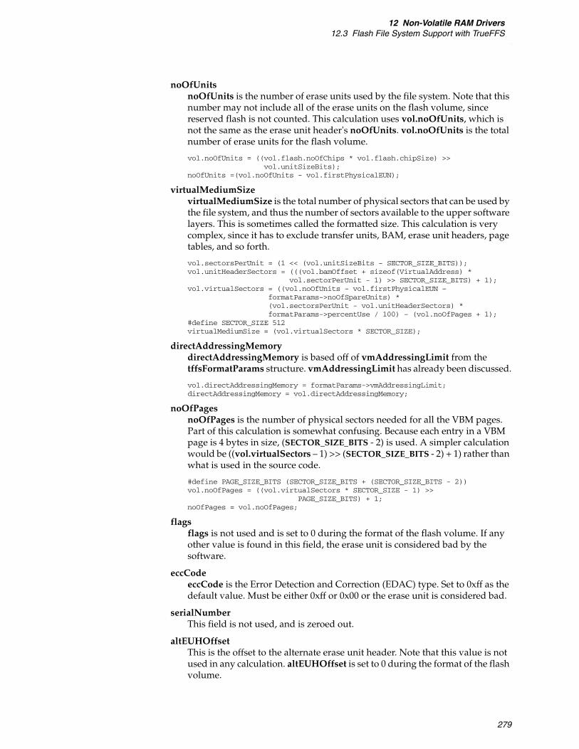
12 Non-Volatile RAM Drivers12.3 Flash File System Support with TrueFFS
279
noOfUnits noOfUnits is the number of erase units used by the file system. Note that this number may not include all of the erase units on the flash volume, since reserved flash is not counted. This calculation uses vol.noOfUnits, which is not the same as the erase unit header's noOfUnits. vol.noOfUnits is the total number of erase units for the flash volume.
vol.noOfUnits = ((vol.flash.noOfChips * vol.flash.chipSize) >> vol.unitSizeBits);
noOfUnits =(vol.noOfUnits - vol.firstPhysicalEUN);
virtualMediumSize virtualMediumSize is the total number of physical sectors that can be used by the file system, and thus the number of sectors available to the upper software layers. This is sometimes called the formatted size. This calculation is very complex, since it has to exclude transfer units, BAM, erase unit headers, page tables, and so forth.
vol.sectorsPerUnit = (1 << (vol.unitSizeBits - SECTOR_SIZE_BITS)); vol.unitHeaderSectors = (((vol.bamOffset + sizeof(VirtualAddress) *
vol.sectorPerUnit - 1) >> SECTOR_SIZE_BITS) + 1);vol.virtualSectors = ((vol.noOfUnits - vol.firstPhysicalEUN –
formatParams->noOfSpareUnits) * (vol.sectorsPerUnit - vol.unitHeaderSectors) *formatParams->percentUse / 100) – (vol.noOfPages + 1);
#define SECTOR_SIZE 512 virtualMediumSize = (vol.virtualSectors * SECTOR_SIZE);
directAddressingMemory directAddressingMemory is based off of vmAddressingLimit from the tffsFormatParams structure. vmAddressingLimit has already been discussed.
vol.directAddressingMemory = formatParams->vmAddressingLimit; directAddressingMemory = vol.directAddressingMemory;
noOfPages noOfPages is the number of physical sectors needed for all the VBM pages. Part of this calculation is somewhat confusing. Because each entry in a VBM page is 4 bytes in size, (SECTOR_SIZE_BITS - 2) is used. A simpler calculation would be ((vol.virtualSectors – 1) >> (SECTOR_SIZE_BITS - 2) + 1) rather than what is used in the source code.
#define PAGE_SIZE_BITS (SECTOR_SIZE_BITS + (SECTOR_SIZE_BITS - 2)) vol.noOfPages = ((vol.virtualSectors * SECTOR_SIZE - 1) >>
PAGE_SIZE_BITS) + 1; noOfPages = vol.noOfPages;
flags flags is not used and is set to 0 during the format of the flash volume. If any other value is found in this field, the erase unit is considered bad by the software.
eccCode eccCode is the Error Detection and Correction (EDAC) type. Set to 0xff as the default value. Must be either 0xff or 0x00 or the erase unit is considered bad.
serialNumber This field is not used, and is zeroed out.
altEUHOffset This is the offset to the alternate erase unit header. Note that this value is not used in any calculation. altEUHOffset is set to 0 during the format of the flash volume.

VxBusDevice Driver Developer's Guide, 6.9
280
BAMoffset BAMoffset is the offset of the BAM with reference to the beginning of the erase unit header. Typically BAMoffset is just sizeof(UnitHeader) which is 0x44 (68). If embeddedCIS of formatParams is anything but 0, the calculation becomes difficult.
vol.bamOffset = sizeof(UnitHeader);
or this if formatParams->embeddedCISlength is not 0
vol.bamOffset = sizeof(UnitHeader) – (sizeof uh->embeddedCIS) + (formatParams->embeddedCISlength + 3) / 4 * 4;
BAMoffset = vol.bamOffset;
reserved 12 bytes. Reserved for future use.
embeddedCIS embeddedCIS is the location of the embedded CIS information. The default size is 4 bytes, which the user can override.
The above fields are derived when the flash volume is formatted. All of these fields are the same for each erase unit in the flash volume except wearLevelingInfo and logicalUnitNo which are specific to an erase unit. When an erase unit is being formatted (or erased), all of these fields are copied from another valid erase unit, except wearLevelingInfo and logicalUnitNo.

281
13Resource Drivers
13.1 Introduction 281
13.2 Overview 281
13.3 VxBus Driver Methods 282
13.4 Header Files 282
13.5 BSP Configuration 282
13.6 Available Utility Routines 283
13.7 Initialization 283
13.8 Debugging 283
13.1 Introduction
This chapter describes resource drivers. This chapter assumes that you are familiar with the contents of the 3. Device Driver Fundamentals, which discusses generic driver concepts as well as details of VxBus that are not specific to any driver class.
13.2 Overview
Many target systems include special purpose resources that can be allocated in one of several ways for use by other devices and drivers. Special purpose resources are typically available when there is a resource in the system that can be used by multiple devices, when a resource is expensive, or when there are more consumer devices for the resource than there are resources available. These resources include hardware elements such as switching and routing systems to transfer bus traffic from a bus controller to the bus it manages.
Management of these resources should be done by a resource driver dedicated to managing the resource. The management can involve allocation of the resource to

VxBusDevice Driver Developer's Guide, 6.9
282
other drivers, startup configuration, or run-time management of a limited resource.
As a rule, resource drivers are highly custom. You can think of these drivers as the glue code that makes the system work correctly.
13.3 VxBus Driver Methods
There are generally two operations that resource drivers perform. First, the driver can allocate some resource. Second, the driver can manage a resource on behalf of some other entity on the system, which may or may not involve allocation to the requestor.
Wind River provides custom methods for resource drivers, for example, {cpmCommand}( ) and {m85xxLawBarAlloc}( ). These custom methods should not be advertised by new drivers, as they are custom-defined for the drivers that already use them, and creating new drivers that advertise these methods causes an adverse impact for other drivers.
The only method that can be used by developers of third-party resource drivers is the generic {driverControl}( ) method. This method is described in 18. Other Driver Classes.
13.4 Header Files
There are no header files that are applicable to resource drivers as a class. However, when a resource driver is written specifically for a single chip, there may be header files shared by the devices on that chip.
13.5 BSP Configuration
Because resource drivers are highly customized, there can be custom BSP requirements for a resource driver. In some cases, this involves allowing the BSP to configure the allocation of resources to drivers that require use of the resources.
For more information on BSP configuration, see 3. Device Driver Fundamentals.

13 Resource Drivers13.6 Available Utility Routines
283
13.6 Available Utility Routines
There are no utility routines available that are specific to resource drivers.
13.7 Initialization
Other drivers in the system may be dependent on resource drivers and may have initialization restrictions of their own. For this reason, resource drivers are often required to complete their initialization in VxBus initialization phase 1 (devInstanceInit( )).
13.8 Debugging
For most development, resource drivers are simple to debug because the system can be completely up before the resource driver is loaded. However, if the system cannot be booted without the resource driver, or if the resource driver is required in order for all peripheral devices to be available for use as a debug interface, then debugging resource drivers can be more complex.
One way of handling this situation is to develop the resource driver as the BSP is being developed. In this case, the BSP developer may be able to hard-wire the resource allocation during initial development. The system can then be booted to a point where normal debug tools are available, and the resource driver completed at that point. To maximize your ability to reuse a given resource driver, be sure to restructure the BSP and resource driver so that the resource driver, and not the BSP, allocates the resources in the deployed system.
For general driver debugging information, see 4. Development Strategies.

VxBusDevice Driver Developer's Guide, 6.9
284
285
14Serial Drivers
14.1 Introduction 285
14.2 Overview 285
14.3 VxBus Driver Methods 286
14.4 Header Files 287
14.5 BSP Configuration 288
14.6 Available Utility Routines 288
14.7 Initialization 288
14.8 Polled Mode Versus Interrupt-Driven Mode 288
14.9 SIO_CHAN and SIO_DRV_FUNCS 289
14.10 WDB 291
14.11 Serial Drivers, Initialization, and Interrupts 291
14.12 Debugging 293
14.1 Introduction
This chapter describes VxBus serial drivers that support RS232, RS422, and other similar devices. This chapter assumes that you are familiar with the contents of 3. Device Driver Fundamentals, which discusses generic driver concepts as well as details of VxBus that are not specific to any driver class.
14.2 Overview
VxBus serial drivers provide an interface to the I/O system similar to the pre-VxBus multi-mode (SIO) serial drivers, but also provide an enhanced initialization mechanism and a simplified interface to the BSP.

VxBusDevice Driver Developer's Guide, 6.9
286
These drivers provide an interface for setting hardware options, such as the number of start bits, stop bits, data bits, parity, and so on. In addition, they provide an interface for polled communication that can provide external mode debugging (such as ROM-monitor style debugging) over a serial line.
Each serial port is associated with an SIO_CHAN structure. When a single device supports more than one port, the device must be able to provide a separate SIO_CHAN structure for each supported port. The contents of the SIO_CHAN structure are defined in:
installDir/vxworks-6.x/target/h/sioLib.h
Many drivers append additional fields to the end of the SIO_CHAN structure, to contain additional information required by the driver.
14.3 VxBus Driver Methods
There are two VxBus driver methods used by serial drivers: {sioChanGet}( ) and {sioChanConnect}( ). Both func{sioChanGet}( ) and func{sioChanConnect}( ) use an SIO_CHANNEL_INFO structure as their second argument. This structure contains two pieces of information:
sioChanNoAn integer value indicating which channel on the system to use.
This corresponds to the number N in the channel name used by the I/O system: /tyCo/N. That is, 0 for /tyCo/0 or 3 for /tyCo/3.
pChanHolds the SIO_CHAN structure pointer discussed in 14.9 SIO_CHAN and SIO_DRV_FUNCS, p.289.
14.3.1 {sioChanGet}( )
The func{sioChanGet}( ) routine retrieves the SIO_CHAN structure associated with the specified serial port.
void func{sioChanGet}(VXB_DEVICE_ID pDev,SIO_CHANNEL_INFO * pInfo)
The SIO_CHANNEL_INFO structure contains fields to specify a port and to return a pointer to the SIO_CHAN structure associated with the port. If the instance manages the specified port, the func{sioChanGet}( ) routine must assign pInfo->pChan with a pointer to the SIO_CHAN structure associated with that port.

14 Serial Drivers14.4 Header Files
287
14.3.2 {sioChanConnect}( )
This driver method is used to connect the specified channel number to the I/O subsystem. There are two alternate forms of this driver method, depending on the channel selected in the SIO_CHANNEL_INFO structure specified as the argument to func{sioChanConnect}( ).
In the first form, a single channel is specified. In this case, the specified channel is connected to the I/O subsystem.
In the second form, the channel value is specified as -1. This value indicates that the driver should connect all channels associated with this instance.
The prototype for the func{sioChanConnect}( ) driver method is:
LOCAL void func{sioChanConnect}(VXB_DEVICE_ID pInst,void * pArg){SIO_CHANNEL_INFO * pInfo = (SIO_CHANNEL_INFO *)pArg;...}
This routine does not return any value, either directly or through the SIO_CHANNEL_INFO structure.
14.4 Header Files
VxBus serial drivers should include the following serial driver header files, in addition to the generic VxBus and other system header files as well as any driver-specific header files.
#include <sioLib.h>#include <hwif/util/sioChanUtil.h>
NOTE: The port specified in the SIO_CHANNEL_INFO structure is identified by the channel number of the serial port on the entire system. Do not assume that the identification is related only to your device. For example, if your device supports four serial ports, and the first port on your device corresponds to /tyCo/2, then the pChan->channelNo field values of 0 and 1 are not intended for your device, and the values of 2 through 5 correspond to the 0, 1, 2, and 3 ports on your device.
NOTE: Recall that an instance is the pairing between a driver and a single device. However, in some cases, a device such as a PCI card may include multiple serial ports. In this case, there are multiple ports for a single instance. Do not confuse this with multiple instances. Only the ports associated with the specified instance should be connected when the func{sioChanConnect}( ) driver method routine is called.

VxBusDevice Driver Developer's Guide, 6.9
288
14.5 BSP Configuration
Serial drivers do not typically require configuration information from a BSP that is above and beyond the normal device-specific information provided for all drivers. For more information on BSP configuration, see 3. Device Driver Fundamentals.
14.6 Available Utility Routines
There are no class-specific utility routines required for serial drivers. However, some of the inline macros defined in installDir/vxworks-6.x/target/h/sioLib.h may be useful for your development. For a complete list of available routines, see the sioLib.h file.
14.7 Initialization
There are two primary consumers of serial devices, both of which impose initialization constraints.
When phase 1 initialization is complete, VxWorks chooses a serial port to be used as a console. Your driver must complete its initialization during phase 1 in order to be used as a console.
Serial ports can also be used for WDB connections for system-mode debugging. The serial port that is used for this purpose is selected after phase 1 initialization is complete. When used for system-mode debugging, polled-mode input and output are required before phase 2 initialization begins.
During initialization, the device should be configured in interrupt mode unless explicitly set to polled-mode using SIO_MODE_SET as specified in 14.9 SIO_CHAN and SIO_DRV_FUNCS, p.289.
For additional information on serial driver initialization, see 14.11 Serial Drivers, Initialization, and Interrupts, p.291.
14.8 Polled Mode Versus Interrupt-Driven Mode
VxWorks serial drivers must provide an interrupt-driven mode for normal operation. Serial drivers can also provide a polled mode for use with WDB, polled
NOTE: The serial port is not used for input or output until the end of phase 2 initialization.
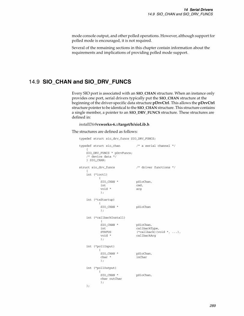
14 Serial Drivers14.9 SIO_CHAN and SIO_DRV_FUNCS
289
mode console output, and other polled operations. However, although support for polled mode is encouraged, it is not required.
Several of the remaining sections in this chapter contain information about the requirements and implications of providing polled mode support.
14.9 SIO_CHAN and SIO_DRV_FUNCS
Every SIO port is associated with an SIO_CHAN structure. When an instance only provides one port, serial drivers typically put the SIO_CHAN structure at the beginning of the driver-specific data structure pDrvCtrl. This allows the pDrvCtrl structure pointer to be identical to the SIO_CHAN structure. This structure contains a single member, a pointer to an SIO_DRV_FUNCS structure. These structures are defined in:
installDir/vxworks-6.x/target/h/sioLib.h
The structures are defined as follows:
typedef struct sio_drv_funcs SIO_DRV_FUNCS;
typedef struct sio_chan /* a serial channel */{SIO_DRV_FUNCS * pDrvFuncs;/* device data */ } SIO_CHAN;
struct sio_drv_funcs /* driver functions */{int (*ioctl)
(SIO_CHAN * pSioChan,int cmd,void * arg);
int (*txStartup)(SIO_CHAN * pSioChan);
int (*callbackInstall)(SIO_CHAN * pSioChan,int callbackType,STATUS (*callback)(void *, ...),void * callbackArg);
int (*pollInput)(SIO_CHAN * pSioChan,char * inChar);
int (*pollOutput)(SIO_CHAN * pSioChan,char outChar);
};

VxBusDevice Driver Developer's Guide, 6.9
290
The members of the SIO_DRV_FUNCS structure function as follows:
ioctl( ) Points to the standard I/O control interface routine. This routine provides the primary control interface for the driver. To access the I/O control services for a standard SIO device, use the following symbolic constants:
SIO_BAUD_SET, SIO_BAUD_GET Sets and retrieves the port baud rate.
SIO_HW_OPTS_SET, SIO_HW_OPTS_GET Sets and retrieves the port hardware options. The available options are: CLOCAL, HUPCL, CREAD, CSIZE, PARENB, and PARODD.
For more information on these options, see:
installDir/vxworks-6.x/target/h/sioLibCommon.h
SIO_MODE_SET, SIO_MODE_GET, SIO_AVAIL_MODES_GET Sets and retrieves the port mode to switch between polled mode and interrupt driven mode, and find which modes are available. Polled mode is specified as SIO_MODE_POLL and interrupt driven mode is specified with SIO_MODE_INT. When SIO_AVAIL_MODES_GET is used, the values of SIO_MODE_POLL and SIO_MODE_INT are logically or-d together as follows:
*(int *)arg = SIO_MODE_INT | SIO_MODE_POLL;
SIO_OPEN Sets modem control lines (RTS and DTR) to TRUE if not already set, and initializes the device for user operation. Only valid if SIO_HUP is supported.
SIO_HUP Resets RTS and DTR signals.
Other ioctl( ) commands can be supported as well. For a more complete list of ioctl( ) commands that can be supported by serial drivers (such as keyboard modes and keyboard LED states), see:
installDir/vxworks-6.x/target/h/sioLibCommon.h
txStartup( ) Provides a pointer to the routine that the system calls when new data is available for transmission. Typically, this routine is called only from the ttyDrv.o module. This module provides a level of functionality that allows a raw serial channel to behave with line control and canonical character processing.
callbackInstall( ) Provides the driver with pointers to callback routines that the driver can call asynchronously to handle character puts and gets. The driver is responsible for saving the callback routines and arguments that it receives from the callbackInstall( ) routine. The available callbacks are SIO_CALLBACK_GET_TX_CHAR and SIO_CALLBACK_PUT_RCV_CHAR.
■ Define SIO_CALLBACK_GET_TX_CHAR to point to a routine that fetches a new character for output. The driver calls this callback routine with the supplied argument and an additional argument that is the address to receive the new output character (if any). The called routine returns OK to

14 Serial Drivers14.10 WDB
291
indicate that a character was delivered, or ERROR to indicate that no more characters are available.
■ Define SIO_CALLBACK_PUT_RCV_CHAR to point to a routine the driver can use to pass characters to the system. For each incoming character, the callback routine is called with the supplied argument, and the new character as a second argument. Drivers normally do not care about the return value from this call. In most cases, there is nothing that a driver can do but drop a character if the I/O system is not able to receive it.
pollInput( ) and pollOutput( ) Provide an interface to polled mode operations of the driver. These routines are not called unless the device has already been placed into polled mode by an SIO_MODE_SET operation.
14.10 WDB
WDB can be configured to use a serial port for communication between the host and target by specifying WDB_COMM_TYPE with the value WDB_COMM_SERIAL. The primary impact of this on serial driver development is that WDB uses polled mode for this communication, therefore a driver without polled mode cannot support this configuration.
14.10.1 WDB and Kernel Initialization
When WDB is used over a serial channel, it puts the SIO driver into polled mode. This mode disables interrupts and performs I/O operations. Eventually, WDB returns the driver to normal interrupt mode operation.
During BSP development, it is possible to use WDB in polled mode before the kernel is available (see VxWorks BSP Developer's Guide). In this case, the WDB target agent issues an ioctl( ) with SIO_MODE_SET as the command in order to set the device into polled mode. Later, the agent puts the driver back into normal interrupt mode. For more information on WDB, see the VxWorks Kernel Programmer's Guide.
14.11 Serial Drivers, Initialization, and Interrupts
There are several issues related to initialization and interrupts that are particular to serial drivers.

VxBusDevice Driver Developer's Guide, 6.9
292
14.11.1 WDB and Interrupts
As a serial driver developer, you must be aware of interactions between serial ports and a WDB connection in addition to kernel initialization. These issues are related to interrupts and the order of system initialization.
When using a serial port for a WDB connection, WDB switches the port between polled mode and normal operation, depending on what WDB is doing at any given time. During system mode debugging—the only debug mode available during system bringup—WDB puts the serial port into polled mode. However, at other times, WDB puts the serial port into normal operation, which usually implies an interrupt-driven mode.
If WDB places the driver into polled mode during system bringup, then later switches to interrupt driven mode, the driver may not have a chance to attach an ISR to the device interrupt. To avoid a stray interrupt—which can cause serious problems with the system—your driver must ensure that the switch from polled mode to interrupt mode does not assume that instance initialization is complete.
Connecting an interrupt requires that the system memory pool be available. However, during the early phases of system initialization, the system memory pool is not available. Your driver must wait until the second phase of VxBus initialization, devInstanceInit2( ), before it can successfully connect an ISR to the device interrupt. Your driver must not switch from polled mode to interrupt mode until this initialization is complete.
The normal calling sequence is as follows:
1. usrRoot( )
2. sysClkConnect( )
3. sysHwInit2( )
4. vxbDevInit( )
5. the driver's devInstanceInit2( ) routine
6. vxbIntConnect( )
If the driver attempts to connect an ISR before usrRoot( ) runs, the attempt fails. Any subsequent interrupts are stray interrupts. These stray interrupts cause problems during system initialization.
14.11.2 Initialization Order and Interrupts
Another issue for serial driver developers is related to the behavior of the actual driver if it attempts to connect interrupts before the kernel is started. When this happens, the SIO driver sometimes loses the ability to function in interrupt mode thereafter, though it generally continues to work in polled mode. This is because the system is likely to overwrite any interrupt connectivity information written before the driver's devInstanceInit2( ) routine. Alternatively, the system can crash during bootup, due to attempts to configure interrupt connectivity before the interrupt subsystem is initialized. As mentioned previously, interrupts cannot be connected before the kernel is started.

14 Serial Drivers14.12 Debugging
293
14.11.3 Initialization Order
For various reasons, VxBus serial drivers must perform the majority of their required initialization in the first phase of the VxBus initialization sequence. This makes them available—in polled mode—to WDB, polled mode console output, and other operations before the I/O system is available. The only initialization that required for serial drivers after the first initialization phase is connection and enabling of interrupts.
14.12 Debugging
When debugging a serial driver, as with all driver development, it is often most convenient to have a fully functional system to test the driver on. This allows the driver developer full access to the debug capabilities of VxWorks and the VxBus show routines, which are helpful when debugging.
This is relatively simple to accomplish for serial drivers, if you are able to develop on a target hardware platform with working PCI. When PCI support is available, you can use one of the PCI serial cards supported by the ns16550 serial driver. You can then change the console to the PCI serial card. This provides you with full access to the VxWorks system when you start debugging your custom serial driver.
For general driver debugging information, see 4. Development Strategies.

VxBusDevice Driver Developer's Guide, 6.9
294

295
15Storage Drivers
15.1 Introduction 295
15.2 Overview 295
15.3 VxBus Driver Methods 296
15.4 Header Files 296
15.5 BSP Configuration 296
15.6 Available Utility Routines 297
15.7 Initialization 297
15.8 Interface with VxWorks File Systems 298
15.9 Writing New Storage Drivers 302
15.10 Debugging 303
15.1 Introduction
This chapter describes storage drivers. This chapter assumes that you are familiar with the contents of the 3. Device Driver Fundamentals, which discusses generic driver concepts as well as details of VxBus that are not specific to any driver class.
15.2 Overview
The VxBus storage driver class currently encompasses parallel and serial ATA (SATA) drivers. These drivers pair with ATA or SATA host controllers to form VxBus instances. While a host controller can have multiple devices connected to it, only the host controller is a VxBus instance.
As in previous VxWorks releases, a monolithic approach has been taken in developing these drivers. Each driver is responsible for providing block device

VxBusDevice Driver Developer's Guide, 6.9
296
management routines, spawning device monitoring and job handling tasks, and performing low-level device access.
VxBus storage drivers provide block device management routines so that various VxWorks file systems can be mounted on the connected device(s). Device monitoring, such as handling connect and disconnect events and interrupts, must also be provided by the storage driver.
15.3 VxBus Driver Methods
VxBus storage drivers do not use or supply any VxBus driver methods. During VxBus initialization phase 3 (devInstanceConnect( )), the driver initializes the controller device and sets up the ability to recognize storage media and announce the media to the XBD block device abstraction layer described in 15.8 Interface with VxWorks File Systems, p.298 and in 15.7 Initialization, p.297.
15.4 Header Files
Although there are no class-specific header files for storage drivers, each storage driver must include the following header files in order to use the higher-level block device and event handling utilities.
#include <drv/xbd/xbd.h>#include <drv/erf/erfLib.h>#include <drv/xbd/bio.h>
15.5 BSP Configuration
Storage drivers do not typically require configuration information from a BSP that is above and beyond the normal device-specific information provided for all drivers.
There are two storage-class specific structures required for this class: ATA_RESOURCE and ATA_TYPE. Some drivers require these structures to be provided by the BSP. If this is the case for your driver, use ataResources and ataTypes as the resource names.
For more information on BSP configuration, see 3. Device Driver Fundamentals.

15 Storage Drivers15.6 Available Utility Routines
297
15.6 Available Utility Routines
This section briefly describes the utility routines available for storage class drivers. These routines are discussed further in 15.8 Interface with VxWorks File Systems, p.298.
erfHandlerRegister( ) and erfHandlerUnregister( )
The erfHandlerRegister( ) routine registers a routine with the error reporting framework (ERF) that is called when the XBD is fully initialized. erfHandlerUnregister( ) deregisters the routine registered by erfHandlerRegister( ).
For more information on these routines, see ERF Registration, p.298.
erfEventRaise( )
The erfEventRaise( ) routine announces to the system that a new device has been added and that it is ready for file system mounting.
For more information on this routine, see 15.8.3 Event Reporting, p.301.
xbdAttach( )
The xbdAttach( ) routine advertises the xbd_funcs structure to the system. The xbd_funcs structure provides the following routines:
■ (*xf_ioctl)( )—provides a single interface to various driver functions such as device eject.
■ (*xf_strategy)( )—queues writes and reads to a given storage device (see 15.8.2 Processing, p.300).
■ (*xf_dump)( )—allows the driver to provide a method for writing data to a device in the event of a system failure.
For more information, see Advertisement of XBD Methods, p.299.
bio_done( )
The bio_done( ) routine is used to mark the bio structure as processed. For more information, see 15.8.2 Processing, p.300.
15.7 Initialization
Because storage drivers depend on the XBD library and other parts of the VxWorks I/O system, they must normally wait until these services are initialized before they
VxBusDevice Driver Developer's Guide, 6.9
298
are initialized. This implies that the bulk of the storage driver initialization must be done in the VxBus initialization phase 3 (devInstanceConnect( )).
Generally, any initialization tasks that make calls—or may potentially lead to calls—to the XBD or ERF libraries must be done no earlier than VxBus initialization phase 3. The is most obvious in the case where device creation is triggered by a device change interrupt.
15.8 Interface with VxWorks File Systems
The storage class drivers utilize two interrelated VxWorks subsystem libraries: eXtended Block Device (XBD) and Event Reporting Framework (ERF). These libraries facilitate the interface between the device drivers and the VxWorks file systems. This section discusses how storage class drivers should use these libraries in different areas of operation.
For more information on the XBD facility, see the VxWorks Kernel Programmer’s Guide: I/O System.
15.8.1 Device Creation
Storage class drivers typically provide a routine that creates the XBD block device structures and reports to the XBD layer when the underlying device is ready to be used. There are two ways to implement this functionality. The Intel ICH driver presents one implementation. This driver is configured to call this routine during system initialization, based on data contained in the BSP hwconf.c file. The Silicon Image driver uses another implementation. This driver uses a port monitoring task to dynamically create block device structures upon device detection. The preferred method for new development is the implementation found in the Silicon Image driver.
The creation routine, regardless of how it is called, is responsible for the following initialization duties:
■ Allocating and initializing the block device structure.
■ Spawning the device service task.
■ Initializing semaphore(s) needed for task synchronization.
■ Registering with the ERF.
■ Advertising XBD methods.
■ Notifying the ERF of a new device.
The last three items are discussed further in the following sections.
ERF Registration
The ERF provides a means for notifying the storage driver that the XBD initialization for the device being created is complete. Your driver should use the
15 Storage Drivers15.8 Interface with VxWorks File Systems
299
routine erfHandlerRegister( ) to register a routine with the ERF. This routine is then called when the XBD is fully initialized. For example:
erfHandlerRegister(xbdEventCategory, xbdEventInstantiated,myDeviceXbdReadyHandler, pMyXbd, 0);
The first two arguments to this routine (xbdEventCategory and xbdEventInstantiated) are global variables defined in the XBD library that correspond to this event being associated with XBD and triggered when the XBD is instantiated. The third argument (myDeviceXbdReadyHandler) is a pointer to the driver routine that is called when this event occurs. The fourth argument (pMyXbd) is the parameter that is passed to the routine. In this case, pMyXbd is a pointer to the driver-specific device structure. The fifth argument is for option flags, and can normally be left as 0.
In most cases, the routine pointed to by myDeviceXbdReadyHandler simply needs to unregister itself from the ERF—using erfHandlerUnregister( )—to avoid being triggered again and then unblock the device creation routine. In this way, the device creation routine does not exit until the XBD initialization, which may occur in a different task context, is complete.
Advertisement of XBD Methods
The xbd_funcs structure is advertised using a call to xbdAttach( ):
int xbdAttach(XBD * xbd,struct xbd_funcs * funcs,const char * name,unsigned blocksize,sector_t nblocks,device_t * result)
The xbd parameter is a pointer to an XBD structure that can be allocated as part of a larger structure describing the device being created. The funcs parameter is a pointer to the xbd_funcs structure described previously. The next three parameters are self-explanatory. The last parameter, result, is a handle for the device that is used, by ERF routines in particular, to identify the device. This parameter is filled in by the xbdAttach( ) routine.
xbd_funcs Structure
The XBD library expects that drivers supply a set of function pointers to provide the XBD library with access to devices. These methods are specified in xbd.h in the xbd_funcs structure as follows:
struct xbd_funcs{int (*xf_ioctl) (struct xbd * dev, int cmd, void * arg);int (*xf_strategy) (struct xbd * dev, struct bio * bio);int (*xf_dump) (struct xbd * dev, sector_t pos, void * data, size_t
size);};
(*xf_ioctl)( )
The (*xf_ioctl)( ) routine provides a single interface to various driver functions such as device eject, power management, and diagnostic reporting. Much of this

VxBusDevice Driver Developer's Guide, 6.9
300
functionality is optional and may not apply in all cases. The ioctl( ) codes used by XBD are defined in xbd.h.
(*xf_strategy)( )
The (*xf_strategy)( ) routine provides a way to queue work to the storage driver. As such, you only need to be concerned with managing linked lists containing the queued work for each device under control of your driver. The work to be done is contained in a bio structure that is defined in bio.h.
(*xf_dump)( )
The (*xf_dump)( ) routine allows the driver to provide a method for writing data to a device in the event of a catastrophic system failure. The underlying routines in your driver must not use any OS services or rely on any interrupt handling.
ERF New Device Notification
The upper layers of software need to be notified about device creation in the system. This is done by raising an event using the ERF routine erfEventRaise( ). For example:
erfEventRaise(xbdEventCategory, xbdEventPrimaryInsert, ERF_ASYNC_PROC,(void *) pDevice, NULL);
The first two arguments (xbdEventCategory and xbdEventPrimaryInsert) are similar to the first two arguments in erfHandlerRegister( ).
The third argument contains a flag indicating what kind of processing is to be performed. The value ERF_ASYNC_PROC indicates that this event can be handled asynchronously, and should be used in most cases. If synchronous handling is required, you must specify ERF_SYNC_PROC.
The fourth argument (in this example, pDevice) is the (void *) cast variable returned in the call to xbdAttach( ). This argument is used to pass device-specific information to the handler function. The type of this variable is dependent on the implementation of the handler. The calling function must use the data type expected by the handler.
The fifth argument is for providing a routine to free the memory pointed to by the fourth argument. Because, in this case, you do not want to free the device pointer, this argument is left as NULL.
15.8.2 Processing
In addition to providing the (*xf_strategy)( ) routine, which the XBD layer uses to queue writes and reads to a storage device, the storage class driver must also contain code to process this queued work. In current implementations, this consists of a task that is awakened through a semaphore given at the end of the (*xf_strategy)( ) routine. This task traverses the linked list of bio structures (which contain details on the access to be performed), and executes each one sequentially.
The storage driver typically extracts the sector number, transaction size (in bytes), and transaction direction (read or write) from the bio structure. After any necessary checking or conversion of this data (for example, converting the

15 Storage Drivers15.8 Interface with VxWorks File Systems
301
transaction size from bytes to sectors), the driver then calls its low-level read or write routines to complete the transaction.
To mark the bio structure as processed, the driver must call the bio_done( ) routine with a pointer to the bio being processed and an errno value indicating the result of the processing.
15.8.3 Event Reporting
The ERF provides routines that drivers can use to alert higher-level software that events have occurred on the system devices and that these events may require their attention.
An example of this is when a storage device is inserted into the system. In response to this event, the storage controller typically raises an interrupt. As part of the handling of this interrupt, the storage driver ISR can wake up a monitoring task that calls the driver device creation routine. Near the end of this routine, a call to erfEventRaise( ) should be made to indicate that a new device has been added to the system and is ready for file system mounting.
Similarly, your driver should also use the ERF when a device is removed from the system. One notable difference is that device removal can originate from the operating system as well as the physical connection to the device. The former case is preferred in systems where data integrity is important, as the operating system delays device removal until all device access has stopped. As the driver developer, you can handle this case in the (*xf_ioctl)( ) routine, by calling the erfEventRaise( ) routine when handling the XBD_HARD_EJECT or XBD_SOFT_EJECT ioctl( ) routines.
Events are raised by making a call to erfEventRaise( ) as follows:
STATUS erfEventRaise(UINT16 eventCat, /* Event Category */UINT16 eventType, /* Event Type */int procType, /* Processing Type */void * pEventData, /* Pointer to Event Data */erfFreePrototype * pFreeFunc /* Function to free Event Data
when done */)
The XBD library includes several defined event types for use with the ERF. The following event types are passed as the second argument (eventType) to erfEventRaise( ):
xbdEventPrimaryInsert This event should be raised near the end of the driver's device creation routine to indicate that a new device has been added to the system.
xbdEventRemoveThis event should be raised during the driver's device deletion routine to indicate that a device has been removed from the system.
xbdEventInstantiated This event should be raised in response to the XBD_STACK_COMPLETE (*xf_ioctl)( ) routine, to acknowledge that the driver is ready for access using the XBD interface.

VxBusDevice Driver Developer's Guide, 6.9
302
xbdEventMediaChanged This event should be raised when the driver detects that the device's removable media has been removed or replaced.
15.9 Writing New Storage Drivers
There is currently no template for storage drivers. For new PCI-based SATA controller drivers, the Silicon Image driver, vxbSI31xxStorage.c can be used as a reference. For most on-board Intel ATA/SATA controllers, vxbIntelIchStorage.c can be used without modification.
If you are writing a new driver, one strategy is to start with issuing ATA commands. In most cases, you must write a minimum of two routines to handle commands. This includes:
■ Command issue—This routine should take (as parameters) the device to which the command is targeted, the command opcode, the desired sector offset, a pointer to a data buffer, and so forth. The routine should then put this information into the format required by the controller. The routine must then complete the necessary register or descriptor accesses to queue this command on the controller.
■ Command result—This routine is called when a command is completed. The result of this command may be to fill in a structure with data returned by the controller. In the course of writing this routine, you may also be required to write an ISR that detects a command complete interrupt and calls this routine, or unblocks a task that calls this routine. In some cases, a polling loop can be used instead.
Once these routines are in place, other routines can be included. For example:
■ Identify—This routine issues a command to retrieve the physical attributes of the connected device. Because retrieval of physical attributes may be required in several places throughout the driver (for example, when a new device is connected), you may want to put this code into a dedicated routine.
■ Read/Write—This routine or set of routines issue either read or write commands. Current Wind River driver implementations use one routine for both read and write. The routine takes a read/write flag as one of its arguments. This implementation reduces redundant code and fits well with the XBD layer, which stores the transaction direction in the bio structure.
Once these routines are implemented, the XBD and ERF interfaces can be added to your driver piece by piece. During this stage of development, some of the routines may need to be altered, and you may need to write the monitoring task if you have not done so already.
Your driver should employ the concept of deferring work to a dedicated task. This method produces several advantages, especially if a task (or set of tasks) is dedicated to each connected device. In this situation, system throughput can be maximized in multiprocessing configurations. However, one important guideline is to ensure that each dedicated task can access only the data structures that belong

15 Storage Drivers15.10 Debugging
303
to it. If this cannot be achieved, some mutual exclusion is required. You may also need to protect accesses to the registers on the controller.
For information on ISR deferral, see the interrupt handling information in 3. Device Driver Fundamentals.
Once the XBD and ERF interfaces are in place, your driver should be ready for use with VxWorks file systems.
15.10 Debugging
When the file system is bypassed, the complexity of debugging storage drivers is decreased. For this reason, the storage driver class includes public low-level access routines.
For example, the Silicon Image driver provides the following sector read/write routine:
STATUS sil31xxSectorRW(int ctrl, /* controller number */int port, /* port number */sector_t sector, /* sector from which to start access */uint32_t numSecs, /* number of sectors to access */char *data, /* data buffer for read or write */BOOL isRead /* TRUE for read, FALSE for write */);
Additionally, the routines for block device creation and deletion should be provided by the driver as public routines to aid in debugging.
For general driver debugging information, see VxWorks4. Development Strategies.

VxBusDevice Driver Developer's Guide, 6.9
304
305
16Timer Drivers
16.1 Introduction 305
16.2 Overview 305
16.3 VxBus Driver Methods 306
16.4 Header Files 309
16.5 BSP Configuration 309
16.6 Available Utility Routines 309
16.7 Initialization 309
16.8 Data Structure Layout 310
16.9 Implementing Driver Service Routines 311
16.10 Integrating a Timer Driver 317
16.11 Debugging 321
16.12 SMP Considerations 321
16.1 Introduction
This chapter describes timer drivers. This chapter assumes that you are familiar with the contents of the 3. Device Driver Fundamentals, which discusses generic driver concepts as well as details of VxBus that are not specific to any driver class.
16.2 Overview
Timer drivers are used to provide a functional interface between hardware timers and the various operating system services that make use of them.

VxBusDevice Driver Developer's Guide, 6.9
306
In VxWorks, timer drivers are used to provide two distinct types of timing services:
■ a periodic interrupt timer
■ a timestamp timer
Timestamp drivers are used to allow middleware to quickly read a timestamp value from a device, in order to place a timestamp value on an event that has occurred in the system. Timestamp drivers typically provide a high degree of precision, with resolutions of a microsecond or less.
Periodic interrupt timer drivers are used to deliver periodic interrupts to an attached interrupt service routine (ISR). This type of driver is used as the basic heartbeat interrupt source for VxWorks. Because VxWorks requires periodic interrupts to perform its scheduling operations, each VxWorks system must include at least one timer driver that supports the generation of periodic interrupts.
This chapter presents the model for both timestamp and periodic interrupt timer drivers. Support for both timestamp and period interrupts can be provided within a single driver, or a driver can choose to provide just one of the two services. A timer driver advertises the services that its hardware supports to the system. Operating system middleware chooses from among the available timers at run time based upon the advertised capabilities of the timer drivers in the system.
Timing hardware often contains more than one timer within a single device. Your timer driver should normally be written so that a single instance supports all of the timers provided by the device hardware.
16.3 VxBus Driver Methods
All timer drivers written in accordance with the VxBus model publish a single driver method, {vxbTimerFuncGet}( ).
Within a timer driver, the {vxbTimerFuncGet}( ) method is implemented using a driver-provided routine with the following prototype:
LOCAL STATUS func{vxbTimerFuncGet}(VXB_DEVICE_ID pInst,struct vxbTimerFunctionality ** ppTimerFunc,int timerNo)
The VXB_DEVICE_ID parameter describes the specific instance (timer device associated with a driver) within the system. Because a single instance of a timer driver can support more than one timer, a timerNo parameter is provided in order to identify the specific timer that is being requested within the instance. If a timer driver supports only a single timer, timerNo should be tested, and ERROR should be returned for all nonzero values of timerNo.
Within func{vxbTimerFuncGet}( ), the driver fills in the contents of the vxbTimerFunctionality structure to describe the capabilities of the requested timer. The fields of the structure are listed in this section, along with a description

16 Timer Drivers16.3 VxBus Driver Methods
307
of each field's use. For the type definition for vxbTimerFunctionality, refer to the following header file:
installDir/vxworks-6.x/target/h/vxbTimerLib.h
This file also includes the following macro definitions:
BOOL allocatedThis field holds a value that is maintained by the driver. The default value for “allocated” is FALSE. When a timer is allocated (using the (*timerAllocate)( ) function pointer, see 16.9.1 (*timerAllocate)( ), p.311), the driver sets this field to TRUE. When a timer is released (using the (*timerRelease)( ) function pointer, see 16.9.2 (*timerRelease)( ), p.311), the driver sets this field to FALSE.
UINT32 clkFrequencyThis field holds a value that describes the frequency (in counts per second) that the timer's hardware counter increments (or decrements) when it is running.
UINT32 minFrequencyThis fields holds a value that describes the minimum frequency (in interrupts per second) that a periodic interrupt timer can support. For timestamp drivers this field is not used.
UINT32 maxFrequencyThis field holds a value that describes the maximum frequency (in interrupts per second) that a period interrupt timer can support. For timestamp drivers this field is not used.
UINT32 featuresThis field holds a bit-significant value that describes the capabilities of the timer. This value is constructed by performing a logical OR operation on the appropriate values from the following #define values found in vxbTimerLib.h:
■ VXB_TIMER_CAN_INTERRUPT—Set if the timer can generate interrupts.
■ VXB_TIMER_INTERMEDIATE_COUNT—Set if the timer allows the hardware to read values while the counter is running without introducing any skew into the timing results.
■ VXB_TIMER_SIZE_16, VXB_TIMER_SIZE_23, VXB_TIMER_SIZE_32—Set if the timer's counter register is 16, 23, or 32 bits (respectively).
■ VXB_TIMER_SIZE_64—Set if the timer's counter register is 64 bits. When this value is set, the driver must also ensure that non-null values are provided for the (*timerEnable64)( ), (*timerRolloverGet64)( ), and (*timerCountGet64)( ) function pointers (see 16.9 Implementing Driver Service Routines, p.311).
■ VXB_TIMER_CANNOT_DISABLE—Set if the underlying hardware timer cannot be disabled.
■ VXB_TIMER_STOP_WHILE_READ—Set if the underlying hardware timer stops incrementing (or decrementing) while the timer is being read.
■ VXB_TIMER_AUTO_RELOAD—Set if the underlying hardware timer automatically reloads itself when it reaches its terminal count, rather than requiring software intervention to restart the timer.

VxBusDevice Driver Developer's Guide, 6.9
308
■ VXB_TIMER_CANNOT_MODIFY_ROLLOVER—Set if the underlying hardware timer's rollover value is fixed at a single value. This is true for timers that (for example) always count from 0 to their maximum value, rather than to a software-controllable intermediate value.
■ VXB_TIMER_CANNOT_SUPPORT_ALL_FREQS—Set if the underlying hardware timer cannot be configured to support interrupt frequencies continuously between minFrequency and maxFrequency.
UINT32 ticksPerSecondThis field holds a value that describes the current configuration of the timer hardware, in terms of interrupts per second that the hardware will generate. A timer driver sets this value to a reasonable default (typically between 60 and 100), and maintains the value whenever the requested interrupt delivery rate changes. See the (*timerEnable)( ) function pointer (see 16.9.6 (*timerEnable)( ), p.314) for further information.
char timerName[MAX_DRV_NAME_LEN + 1]This field holds the name of the timer driver. It is used for debug purposes. Timer drivers that support more than one timer within a single driver can choose to create a name that combines the name for the driver with the timer number. Timer drivers that only support a single timer should set this field to the name of the driver.
UINT32 rolloverPeriodThis field holds a UINT32 that describes how long the timer takes to roll over, in seconds. Timers that count quickly have a shorter rollover period than those that count more slowly.
The following function pointers are described in 16.9 Implementing Driver Service Routines, p.311:
■ STATUS (*timerAllocate)
■ STATUS (*timerRelease)
■ STATUS (*timerRolloverGet)
■ STATUS (*timerCountGet)
■ STATUS (*timerDisable)
■ STATUS (*timerEnable)
■ STATUS (*timerISRSet)
■ STATUS (*timerEnable64)
■ STATUS (*timerRolloverGet64)
■ STATUS (*timerCountGet64)
After the driver's func{vxbTimerFuncGet}( ) routine is called, the various supported timer devices associated with the driver are available for allocation.

16 Timer Drivers16.4 Header Files
309
16.4 Header Files
All timer drivers written in accordance with the VxBus model need to include a single header file to provide the data types required for the driver:
#include <vxbTimerLib.h>
16.5 BSP Configuration
Timer drivers do not typically require configuration information from a BSP that is above and beyond the normal device-specific information provided for all drivers. However, when writing a device driver, you should adhere to the existing standard when choosing resource names. The following resource names are used frequently within the existing set of Wind River timer drivers. If your driver allows any of the properties described for these resources to be configured using a BSP resource file, the following strings should be used to query those resources:
cpuClkRateThe frequency of the CPU clock, in ticks per second. This is useful in timer drivers where the timing hardware runs at a rate that is correlated with the CPU clock.
clkRateMinThe minimum number of interrupts per second that the timer driver hardware can be configured for.
clkRateMaxThe maximum number of interrupts per second that the timer driver hardware can be configured for.
clkFreqThe frequency of the hardware timer.
16.6 Available Utility Routines
There are no class-specific utility routines required or available for timer drivers.
16.7 Initialization
Timer drivers perform their initialization during the first two phases of VxBus initialization:

VxBusDevice Driver Developer's Guide, 6.9
310
■ During VxBus initialization phase 1 (devInstanceInit( )), timer drivers should initialize all of their internal data structures, and perform any required initialization of the timer hardware.
■ During VxBus initialization phase 2 (devInstanceInit2( )), timer drivers should connect their driver-specific ISR to the timer interrupt source(s).
Because any periodic interrupt timer driver can potentially be used as the heartbeat interrupt for the VxWorks kernel, the timer driver must be fully configured by the end of initialization phase 2.
16.8 Data Structure Layout
Figure 16-1 describes a recommended layout for the time driver data structure.
The two principal elements to this data structure are the VXB_DEVICE_ID instance data (by convention referred to as pInst), and the driver-specific data structure, which in this figure is labeled as struct myTimerData. Note that each of these data structures contains a pointer to the other; the pInst->pDrvCtrl field contains a pointer to the driver-specific data structure, and the driver-specific data structure contains a pointer back to the pInst.
When a timer driver initializes itself, it typically allocates its struct myTimer using hwMemAlloc( ), and then initializes the various data structures contained within it. This includes initializing the pointer(s) to pInst. Because the VXB_DEVICE_ID pInst pointer is not provided to the service routines, the stored pointer(s) to pInst is useful to the timer driver service routines.
Figure 16-1 Recommended Timer Driver Data Structure Layout
pDrvCtrl
...
...
struct
vxbTimerFunctionality
.
.
.
struct
vxbTimerFunctionality
struct myTimerData
pInst
struct myTimerData
pInst
VXB_DEVICE_ID struct myTimer(pInst)
Timer N
Timer 0
pTimer
16 Timer Drivers16.9 Implementing Driver Service Routines
311
This documentation in this chapter assumes that the service routines are capable of accessing data within VXB_DEVICE_ID, even when VXB_DEVICE_ID is not provided as a passed-in parameter to the service routine.
16.9 Implementing Driver Service Routines
Once a driver is registered with VxBus and a call is made to the driver's func{vxbTimerFuncGet}( ) routine, all subsequent interaction between the system and the driver occurs through the routines whose pointers are returned within the vxbTimerFunctionality data structure. In the following sections, each of the service routines that can be supported by a timer driver are described. Not all of the service routines need to be implemented in a single driver. For each service routine, a note describing whether the service routine is required for a periodic interrupt driver, a timestamp driver, or for both types of drivers is provided.
16.9.1 (*timerAllocate)( )
The (*timerAllocate)( ) routine is used to allocate a specific timer within a running VxWorks system. Both periodic interrupt and timestamp drivers are required to support this routine.
The prototype for this routine is:
STATUS (*timerAllocate)(VXB_DEVICE_ID pInst, /* IN */UINT32 flags, /* IN */void ** pCookie, /* OUT */UINT32 timerNo /* IN */);
This routine tests its input parameters to ensure that it can comply with the requested allocation. If the requested timer (specified by timerNo) is available, and if the requested timer supports the requested services (specified by the flags parameter), the driver:
■ Marks the driver as allocated by setting the allocated field to TRUE within the vxbTimerFunctionality field associated with the timer hardware.
■ Configures the timer hardware (if required, based on the flags parameter).
■ Sets *pCookie to the base address of the per-timer data area.
■ Returns OK.
If the requested timer does not exist, or if the timer cannot be configured according to the properties described in the flags parameter, the driver returns ERROR.
16.9.2 (*timerRelease)( )
The (*timerRelease)( ) routine is used to release a specific timer that was previously allocated using (*timerAllocate)( ). Both period interrupt and timestamp drivers are required to support this routine.

VxBusDevice Driver Developer's Guide, 6.9
312
The prototype for this routine is:
STATUS (*timerRelease)(VXB_DEVICE_ID pInst, /* IN */void * pCookie /* IN */);
The void * parameter provided using pCookie points to the per-timer data area previously returned through a call to (*timerAllocate)( ). The driver verifies that the requested timer is allocated. If the timer is allocated, the driver:
■ Clears the allocation of the driver by setting the allocated field to FALSE within the vxbTimerFunctionality field associated with the timer hardware.
■ Disables delivery of any interrupts from this timer source.
■ Clears any associated ISR information from the per-timer data area.
■ Returns OK.
If the requested timer is not currently allocated, the driver returns ERROR.
16.9.3 (*timerRolloverGet)( )
The (*timerRolloverGet)( ) routine is used to query the maximum value that the timer is capable of returning using its (*timerCountGet)( ) routine (see 16.9.4 (*timerCountGet)( ), p.312). Timestamp drivers are required to support this routine. This routine is not used for periodic interrupt drivers.
The prototype for this routine is:
STATUS (*timerRolloverGet)(void * pCookie, /* IN */UINT32 * pCount /* OUT */);
The void * parameter provided through pCookie points to the per-timer data area previously returned through a call to (*timerAllocate)( ). The driver should test both pCookie and pCount to ensure that they are both non-null. If both pointers are valid, the driver:
■ Sets *pCount to the maximum value returnable from (*timerCountGet)( ).
■ Returns OK
If either pointer is NULL, the driver returns ERROR.
16.9.4 (*timerCountGet)( )
The (*timerCountGet)( ) routine is used to query the current value of the timer. Timestamp drivers are required to support this routine. This routine is not used for periodic interrupt drivers.
NOTE: In VxWorks, timers always count towards higher numeric values. If the underlying hardware on which the timer is based counts downward, the driver must perform the appropriate mathematics to ensure that the counter appears to count towards higher values from the caller's perspective.

16 Timer Drivers16.9 Implementing Driver Service Routines
313
The prototype for this routine is:
STATUS (*timerCountGet)(void * pCookie, /* IN */UINT32 * pCount /* OUT */);
The void * parameter provided using pCookie points to the per-timer data area previously returned through a call to (*timerAllocate)( ). Your driver should test both pCookie and pCount to ensure that they are both non-null. If both pointers are valid, the driver:
■ Sets *pCount to the current value of the hardware counter, with appropriate math operations to ensure that counter appears to be counting towards higher values.
■ Returns OK.
If either pCookie or pCount are NULL, the driver returns ERROR.
When a timer driver is used as the timestamp source for Wind River System Viewer, the kernel makes calls to (*timerCountGet)( ) at unpredictable times, such as when the kernel has interrupts locked, or while a spinlock is held. To allow (*timerCountGet)( ) to function correctly when used in this situation, the use of spinlocks is not allowed within (*timerCountGet)( ). In addition, the body of (*timerCountGet)( ) must not perform any operations that result in a Wind River System Viewer event, because this causes an infinite recursion between System Viewer and the timer driver.
For a discussion of event logging and examples of operating system facilities that generate System Viewer events, see the Wind River System Viewer User's Guide.
16.9.5 (*timerDisable)( )
The (*timerDisable)( ) routine is used to disable interrupts generated by the underlying timer hardware. Periodic interrupt drivers are required to support this routine.
The prototype for this routine is:
STATUS (*timerDisable)(void * pCookie /* IN */);
The void * parameter provided using pCookie points to the per-timer data area previously returned through a call to (*timerAllocate)( ). The driver should test pCookie to ensure that it is non-null. If pCookie is valid, the driver:
■ Disables interrupt generation for the requested hardware timer.
■ Returns OK.
If pCookie is NULL, the driver returns ERROR.
NOTE: Because this routine is used to create timestamps for events that can occur at a high frequency, it should be implemented as efficiently as possible in order to minimize its effect on overall system performance.

VxBusDevice Driver Developer's Guide, 6.9
314
16.9.6 (*timerEnable)( )
The (*timerEnable)( ) routine is used to enable generation of interrupts by the underlying timer hardware. Periodic interrupt drivers are required to support this routine.
The prototype for this routine is:
STATUS (*timerEnable)(void * pCookie, /* IN */UINT32 maxTimerCount /* IN */);
The void * parameter provided using pCookie points to the per-timer data area previously returned through a call to (*timerAllocate)( ). The driver should test pCookie to ensure that it is non-null. If pCookie is valid, the driver:
■ Programs the underlying timer hardware so that it generates an interrupt each time maxTimerCount counts have occurred within the timer.
■ Enables interrupt generation for the requested hardware timer.
■ Returns OK.
If pCookie is NULL, the driver returns ERROR.
16.9.7 (*timerISRSet)( )
The (*timerISRSet)( ) routine is used to connect an ISR to the underlying timer hardware interrupt. Both periodic interrupt and timestamp drivers are required to support this routine (if your hardware supports interrupt generation).
NOTE: If the timer unit is always used as a free running counter—such as a timestamp timer or a delay timer—and the timer unit has the following characteristics:
■ It starts at power on with the maximum count value supported by the hardware.
■ The counter value is automatically rolled over when it reaches the maximum count.
This routine can return OK with no other operations. (For an example, see the vxbIntelTimestamp driver.)

16 Timer Drivers16.9 Implementing Driver Service Routines
315
The prototype for this routine is:
STATUS (*timerISRSet)(void * pCookie, /* IN */void (*pIsr)(_Vx_usr_arg_t), _Vx_usr_arg_t arg );
The void * parameter provided using pCookie points to the per-timer data area previously returned through a call to (*timerAllocate)( ). The pIsr and arg parameters are caller-provided values that should be stored within the per-timer data area so that the values can be retrieved during interrupt handling for the timer hardware.
After (*timerISRSet)( ) is called to connect the requested ISR to the timer interrupt, the specified ISR is called each time a timer interrupt occurs, using the following code fragment:
(*pIsr)(arg);
16.9.8 (*timerEnable64)( )
The (*timerEnable64)( ) routine is used to enable generation of interrupts by the underlying timer hardware for timers that support 64-bit counters. Support for 64-bit timers is optional. As such, neither timestamp drivers nor periodic interrupt drivers are required to support this routine.
If you want to include support for 64-bit timers, this routine should be supported by the driver. In addition, the VXB_TIMER_SIZE_64 property should be added to the features field of the vxbTimerFunctionality structure that is returned from func{vxbTimerFuncGet}( ).
The prototype for this routine is:
STATUS (*timerEnable64)(void * pCookie, /* IN */UINT64 maxTimerCount /* IN */);
The void * parameter provided using pCookie points to the per-timer data area previously returned through a call to (*timerAllocate)( ). The driver should test pCookie to ensure that it is non-null. If pCookie is valid, the driver:
■ Programs the underlying timer hardware so that it generates an interrupt each time maxTimerCount counts occur within the timer.
■ Enables interrupt generation for the requested hardware timer.
■ Returns OK.
If pCookie is NULL, the driver returns ERROR.
16.9.9 (*timerRolloverGet64)( )
The (*timerRolloverGet64)( ) routine is used to query the maximum value that the timer is capable of returning using its (*timerCountGet64)( ) routine. Support for 64-bit timers is optional. As such, neither timestamp drivers nor periodic interrupt drivers are required to support this routine.
VxBusDevice Driver Developer's Guide, 6.9
316
If you want to include support for 64-bit timers, this routine should be supported by the driver. In addition, the VXB_TIMER_SIZE_64 property should be added to the features field of the vxbTimerFunctionality structure that is returned from func{vxbTimerFuncGet}( ).
The prototype for this routine is:
STATUS (*timerRolloverGet64)(void * pCookie, /* IN */UINT64 * pCount /* OUT */);
The void * parameter provided using pCookie points to the per-timer data area previously returned through a call to (*timerAllocate)( ). The driver should test both pCookie and pCount to ensure that they are both non-null. If both pointers are valid, the driver:
■ Sets *pCount to the maximum value returnable from (*timerCountGet64)( ).
■ Returns OK
If either pointer is NULL, the driver returns ERROR.
16.9.10 (*timerCountGet64)( )
The (*timerCountGet64)( ) routine is used to query the current value of the timer for 64-bit timers. Support for 64-bit timers is optional. As such, neither timestamp drivers nor periodic interrupt drivers are required to support this routine.
The prototype for this routine is:
STATUS (*timerCountGet64)(void * pCookie, /* IN */UINT64 * pCount /* OUT */);
The void * parameter provided using pCookie points to the per-timer data area previously returned through a call to (*timerAllocate)( ). The driver should test both pCookie and pCount to ensure that they are both non-null. If both pointers are valid, the driver:
■ Sets *pCount to the current value of the hardware counter, with appropriate math operations to ensure that counter appears to be counting towards higher values.
■ Returns OK.
If either pCookie or pCount are NULL, the driver returns ERROR.
NOTE: In VxWorks, timers always count towards higher numeric values. If the underlying hardware on which the timer is based counts downward, the driver must perform the appropriate mathematics to ensure that the counter appears to count towards higher values from the caller's perspective.
NOTE: Because this routine is used to create timestamps for events that can happen at a high frequency, it should be implemented as efficiently as possible in order to minimize its effect on overall system performance.

16 Timer Drivers16.10 Integrating a Timer Driver
317
16.10 Integrating a Timer Driver
Traditionally, VxWorks uses between one and three different timers in a running system. All VxWorks operating systems use a standard periodic interrupt timer driver to support the kernel's heartbeat interrupt. Additionally, if a system is configured to support an auxiliary timer or timestamp driver, these services also make use of the timer drivers that are implemented according to this chapter. The following sections discuss the integration of timer drivers to the system clock, auxiliary clock, and to the timestamp driver.
16.10.1 VxWorks System Clock
Prior to VxWorks 6.5, the system clock is commonly implemented directly within the BSP. The BSP is expected to either directly implement (or to include using a #include) the following set of system clock (sysClk*( )) routines:
■ sysClkConnect( )
■ sysClkEnable( )
■ sysClkDisable( )
■ sysClkRateSet( )
■ sysClkRateGet( )
As of VxWorks 6.6, this model has been enhanced to allow the kernel's system clock to be implemented within the BSP, or by using a VxBus timer driver as described in this chapter. In this release, one implementation of the system clock API is implemented within:
installDir/vxworks-6.x/target/src/hwif/util/vxbSysClkLib.c
All of the system clock routines listed previously are implemented in vxbSysClkLib.c. In addition to the required system clock routines, this library contains code to allocate a periodic interrupt timer driver during system startup, and to connect this timer driver to the system clock routines.
Graphically, the system clock consists of three layers as shown in Figure 16-2.

VxBusDevice Driver Developer's Guide, 6.9
318
During system initialization, the available periodic interrupt timer sources are scanned by the system clock library, and one of the available timer sources is selected for use as the timer source for the heartbeat interrupt.
During driver development, you may wish to force the system clock library to choose your periodic interrupt timer driver, rather than one of the other available timer drivers in the system. The system clock library supports this feature through the use of three global variables that are defined within the library as follows:
char * pSysClkName = SYSCLK_TIMER_NAME; UINT32 sysClkDevUnitNo = SYSCLK_TIMER_UNIT; UINT32 sysClkTimerNo = SYSCLK_TIMER_NUM;
If these global variables are redefined in a BSP during execution of the sysHwInit( ) routine, the vxbSysClkLib library uses the timer driver that is described by the global variables instead of the one found through its matching algorithm. The vxbSysClkLib library performs a case-sensitive string comparison of pSysClkName with the names of each of the available timer drivers (as described by the timerName field in the vxbTimerFunctionality structure returned by the driver). If the driver name matches the name specified using pSysClkName, the vxbSysClkLib library compares the unit number and the timer number of the driver against the values specified by BSP. If an exact match is found, the vxbSysClkLib library uses the specified timer.
Note that if an exact match is not found, vxbSysClkLib reverts to using its matching algorithm, rather than failing to connect the kernel's system clock to an underlying timing source. If this occurs, the vxbSysClkLib library post an error detection and reporting message indicating the failure to find the requested timer.
Figure 16-2 VxWorks System Clock Hierarchy
Timer
installDir/vxworks-6.x/target/src/hwif/util/
VxWorks Operating System
vxbSysClkLib.c
Driver 1.....Timer
Driver 2
Timer
Driver 3
Timer
Driver N
Calls routines in
Calls routines in
Bindingoccurs at systemstartup
16 Timer Drivers16.10 Integrating a Timer Driver
319
16.10.2 VxWorks Auxiliary Clock
Prior to VxWorks 6.5, the auxiliary clock is commonly implemented directly within the BSP. The BSP is expected to either directly implement (or to include using a #include) the following set of sysAuxClk*( ) routines:
■ sysAuxClkConnect( )
■ sysAuxClkEnable( )
■ sysAuxClkDisable( )
■ sysAuxClkRateGet( )
■ sysAuxClkRateSet( )
As of VxWorks 6.6, this model has been changed to allow the kernel's auxiliary clock to be implemented using a VxBus timer driver as described in this chapter. In this release, the VxWorks auxiliary clock API is implemented within:
installDir/vxworks-6.x/target/src/hwif/util/vxbAuxClkLib.c
All of the sysAuxClk*( ) routines listed previously are implemented in vxbAuxClkLib.c. In addition to the required sysAuxClk*( ) routines, this library contains code to allocate a periodic interrupt timer driver during system startup, and to connect this timer driver to the sysAuxClk*( ) routines.
During system initialization, the available periodic interrupt timer sources are scanned by the vxbAuxClkLib library, and one of the available timer sources is selected for use as the timer source for the auxiliary clock.
During driver development, you may wish to force the vxbAuxClkLib library to choose your periodic interrupt timer driver, rather than one of the other available timer drivers in the system. The vxbAuxClkLib library supports this feature through the use of three global variables that are defined within the library as follows:
char * pAuxClkName = AUXCLK_TIMER_NAME;UINT32 auxClkDevUnitNo = AUXCLK_TIMER_UNIT;UINT32 auxClkTimerNo = AUKCLK_TIMER_NUM;
If these global variables are redefined in a BSP during execution of the BSP sysHwInit( ) routine, the vxbAuxClkLib library uses the timer driver that is described by the global variables instead of the one found through its matching algorithm. The vxbAuxClkLib library performs a case-sensitive string comparison of pAuxClkName with the names of each of the available timer drivers (as described by the timerName field of the vxbTimerFunctionality returned by the driver). If the driver name matches the name specified using pAuxClkName, the vxbAuxClkLib library compares the unit number and the timer number of the driver against the values specified by the BSP. If an exact match is found, the vxbAuxClkLib library uses the specified timer.
Note that if no exact match is found, the vxbAuxClkLib library reverts to using its matching algorithm, rather than failing to connect the kernel's system clock to an underlying timing source. If this occurs, the vxbAuxClkLib library posts an error detection and reporting message indicating the failure to find the requested timer.

VxBusDevice Driver Developer's Guide, 6.9
320
16.10.3 VxWorks Timestamp Driver
Prior to VxWorks 6.5, the system timestamp driver is commonly implemented directly within the BSP. The BSP is expected to either directly implement (or to include using a #include) the following set of timestamp routines:
■ sysTimestampConnect( )
■ sysTimestampEnable( )
■ sysTimestampDisable( )
■ sysTimestampPeriod( )
■ sysTimestampFreq( )
■ sysTimestamp( )
■ sysTimestampLock( )
As of VxWorks 6.6, this model has been changed to allow the system timestamp to be implemented using a VxBus timer driver as described in this chapter. In this release, the VxWorks timestamp driver API is implemented in:
installDir/vxworks-6.x/target/src/hwif/util/vxbTimestampLib.c
All of the routines listed previously are implemented in vxbTimestampLib.c. In addition to the required sysTimestamp*( ) routines, this library contains code to allocate a timestamp timer driver during system startup, and to connect this timer driver to the sysTimestamp*( ) routines.
During system initialization, the available timestamp timer sources are scanned by the vxbTimestampLib library, and one of the available timer sources is selected for use as the timer source for the timestamp.
During driver development, you may wish to force the vxbTimestampLib library to choose your timestamp timer driver, rather than one of the other available timer drivers in the system. The vxbTimestampLib library supports this feature through the use of three global variables that are defined within the library as follows:
char * pTimestampTimerName = NULL;UINT32 timestampDevUnitNo = 0;UINT32 timestampTimerNo = 0;
If these global variables are redefined in a BSP during execution of the BSP sysHwInit( ) routine, the vxbTimestampLib library uses the timer driver that is described by the global variables instead of the one found through its matching algorithm. The vxbTimestampLib library performs a case-sensitive string comparison of pSysClkName with the names of each of the available timer drivers (as described by the timerName field in the vxbTimerFunctionality structure returned by the driver). If the driver name matches the name specified using pSysClkName, the vxbTimestampLib library compares the unit number and the timer number of the driver against the values specified by BSP. If an exact match is found, the vxbTimestampLib library uses the specified timer.
Note that if no exact match is found, the vxbTimestampLib library reverts to its matching algorithm, rather than failing to connect the timestamp driver to an underlying timing source. If this occurs, the vxbTimestampLib library posts an error detection and reporting message indicating the failure to find the requested timer.

16 Timer Drivers16.11 Debugging
321
16.11 Debugging
When debugging a timer driver, as with all driver development, it is convenient to have a fully functional system to test the driver on. A fully functioning system provides you with full access to the debug capabilities of VxWorks as well as the VxBus show routines. Because timer drivers can be allocated to the VxWorks system clock during system boot, use a functional timer driver as the VxWorks system clock, so that VxWorks can boot into a fully functional system that you can then use to debug your timer driver.
The simplest way to prevent your driver from being selected as the system clock is to delay the registration of your timer driver until after the system has booted. When you delay registration, your driver is unavailable during the period when the system clock is evaluated, therefore it cannot be selected as the system clock.
For general driver debugging information, see 4. Development Strategies.
16.12 SMP Considerations
In VxWorks SMP, any CPU in the system can utilize the services of a timestamp driver. This can present a unique problem if CPU-specific registers are used to implement a timestamp service. For example, on the MIPS architecture, the CPU C0_COUNT and C0_COMPARE registers are often used for timestamping. However, these registers are not necessarily synchronized across the various cores in an SMP system. If these registers are not synchronized in the SMP system, the timestamp driver using these registers returns inconsistent results unless it is only used on a single CPU within the system.
If CPU-specific registers are used as a time base for a timer driver, the registers must be synchronized across all CPUs in the SMP system. The steps required to synchronize these registers is, by definition, architecture and CPU-specific. Unless your driver handles this situation, you should not advertise the VXB_TIMER_INTERMEDIATE_COUNT capability when compiled for SMP.
For more information on SMP considerations for drivers, see 3. Device Driver Fundamentals. For more information on the optional VxWorks SMP product as a whole, see the VxWorks Kernel Programmer’s Guide.

VxBusDevice Driver Developer's Guide, 6.9
322

323
17USB Drivers
17.1 Introduction 323
17.2 Wind River USB Overview 323
17.3 Host Controller and Root Hub Class Drivers 324
17.1 Introduction
This chapter assumes that you are familiar with the contents of 3. Device Driver Fundamentals, which discusses generic driver concepts as well as details of VxBus that are not specific to any driver class.
This chapter includes general information on the Wind River USB product with respect to device driver development. The focus of the chapter is on those USB device drivers that comply with the VxBus device driver model. Other driver types are mentioned briefly. For complete information on Wind River USB, including information on device drivers that do not conform to the VxBus driver model, see the Wind River USB Programmer’s Guide.
17.2 Wind River USB Overview
Wind River USB provides support for the Universal Serial Bus for both USB transaction initiators (USB hosts) and to allow a VxWorks target to act as a USB peripheral. The USB host (sometimes called the USB host stack) and the USB peripheral (sometimes called the USB target stack) conform to the USB 2.0 specification and, depending on the hardware, offer data rates up to 480 Mb/s.
NOTE: The Wind River USB stack do not support the USB On-The-Go (OTG) HNP or SRP protocols.

VxBusDevice Driver Developer's Guide, 6.9
324
17.2.1 USB Host Stack Drivers
The USB host stack consists of the USB driver (USBD), host controller drivers, hub drivers, and class drivers.
Wind River provides host controller drivers (HCDs) for the Enhanced Host Controller Interface (EHCI), the Universal Host Controller Interface (UHCI), the Open Host Controller Interface (OHCI), the Mentor Graphics Host Controller Interface (MHCI), and the Synopsys Host Controller Interface (SynopsysHCI). In addition, Wind River USB provides root hub drivers for the USB controllers, a generic hub class driver, and a collection of class drivers for various types of USB peripherals.
VxBus Model Drivers
USB host controller drivers and root hub drivers comply with the VxBus device driver model. These drivers are discussed further in, see 17.3 Host Controller and Root Hub Class Drivers, p.324.
Other Host Drivers
USB class drivers do not adhere to the VxBus model. Instead, they rely on the interfaces associated with the USBD to connect USB devices to the appropriate class driver. For more information on writing USB class drivers, see the Wind River USB Programmer’s Guide.
The USBD is not a true device driver in the sense that it does not directly control hardware. Rather it serves as the central interface layer between the various USB components. There is one and only one USBD in each VxWorks USB host image. The USBD is not a VxBus model driver. The driver is started in a manner similar to an application program.
17.2.2 USB Target Stack
The Wind River target or peripheral stack provides drivers for a number of target controller drivers (TCDs) as well as emulation software for a variety of target devices such as bulk storage, printers, and so forth. TCDs are not VxBus compliant and are not discussed in this documentation. For information on writing target controller drivers, see the Wind River USB Programmer’s Guide.
17.3 Host Controller and Root Hub Class Drivers
USB devices are initially plugged into a USB hub or root hub. The USB host reads the configuration descriptors, device descriptors, and interface descriptors from
NOTE: For information on the USBD, consult the USB Specification 2.0 available from http://www.usb.org.

17 USB Drivers17.3 Host Controller and Root Hub Class Drivers
325
the device and attaches the device to the appropriate class driver. The class driver then issues commands to the USBD which in turn commands the appropriate host controller driver and hub driver to perform the USB transactions necessary for the system to use the device.
USB host controller drivers are VxBus-compliant and are used by the USBD to execute USB transactions in conjunction with the hub drivers.
Root hub drivers are also VxBus compliant. The root hub drivers are subordinate to the host controller driver and are loaded by VxBus during the instantiation of the host controller.
Wind River provides a generic hub class driver that is instantiated as needed to support downstream hubs. Both the host controller drivers and the hub drivers are controlled by the USBD through calls to and from the class drivers. The USBD interface software provides an API that is used to interface with both the host controller drivers and the hub. Application code is not typically aware of the controller or hub on which the transactions take place.
17.3.1 VxBus Driver Methods
The host controller drivers and the root hub drivers define the {vxbDrvUnlink}( ) driver method. This routine is responsible for the orderly shutdown of the host controller hardware and de-registration of the bus with the USBD.
In the case of the VxBus root hub class driver, func{vxbDrvUnlink}( ) is responsible for disconnecting all downstream devices as well as the hub itself. This routine is called when a hub is disconnected from USB. The func{vxbDrvUnlink}( ) routine performs the disconnect by calling the remove routine provided by each class driver for each device connected to the hub.
STATUS func{vxbDrvUnlink}(VXB_DEVICE_ID devID)
17.3.2 Header Files
The host controller drivers (HCDs) and root hub class drivers use an operating system abstraction layer (OSAL) that provides customized operating system services to the drivers. These services are defined in usbOsal.h.
#include <usb/usbOsal.h>
The HCD and root hub class drivers are responsible for both initiating action on and executing commands issued by the USBD. The USBD interface is defined in usbHst.h.
#include <usb/usbHst.h>
NOTE: Care should be taken to use the operating system services provided in the OSAL rather than the corresponding VxWorks services. In particular, OS_MALLOC( ) should be used rather than the general purpose malloc( ) routine. Failure to use these services correctly can result in unpredictable system behavior.

VxBusDevice Driver Developer's Guide, 6.9
326
17.3.3 BSP Configuration
The majority of USB HCDs reside on the PCI bus. For these devices, the VxBus integration with the USB HCDs takes care of the HCD registration, host controller device detection, base address mapping, interrupt connection, and so forth. This leaves the BSP developer to write the address translation routines that translate CPU addresses to addresses used by the HCD and vice versa, if necessary.
Should a mapping be necessary, the default translation methods can be overridden in the BSP hwconf.c file with entries as shown in the following example. The resource cpuToBus translates a CPU address to an address understandable by the HCD. The resource busToCpu translates an HCD address to an address understandable by the CPU.
const struct hcfResource pentiumPci0Resources[] ={
...
... #ifdef INCLUDE_USB
{ "cpuToBus", HCF_RES_ADDR, {(void *) usbMemToPci}},{ "busToCpu", HCF_RES_ADDR, {(void *) usbPciToMem}},
#endif}
Some USB HCDs reside on the PLB rather than the PCI. In these cases, additional hwconf.c entries are needed.
The first of these entries informs VxBus of the existence of the PLB device.
const struct hcfDevice hcfDeviceList[] = {... ... { "vxbPlbUsbXXXX", 0, VXB_BUSID_PLB, 0, vxbPlbUsbXXXDevNum0,vxbPlbUsbXXXDevResouces0},{ "vxbPlbUsbXXXX", 1, VXB_BUSID_PLB, 0, vxbPlbUsbXXXDevNum1,vxbPlbUsbXXXDevResources1},...
}
The next entries provide the base address, interrupt vector, interrupt level information, and so forth for each of the devices described in hcfDeviceList[ ]. If necessary, the address conversion routines are also defined.
const struct hcfResource vxbPlbUsbXXXDevResouces0 [] = {{ "regBase", HCF_RES_INT, { (void *)0x8000 }},{ "irq", HCF_RES_INT, {(void *)INUM_TO_IVEC(INT_NUM_0)}},{ "irqLevel", HCF_RES_INT, {(void *)INT_NUM_0}},{ "cpuToBus", HCF_RES_ADDR, {(void *) usbMemToBus}},{ "busToCpu", HCF_RES_ADDR, {(void *) usbBusToMem}},
};#define vxbPlbUsbXXXDevNum0 NELEMENTS(vxbPlbUsbXXXDevResouces0)
Endian Conversion for USB Data Transfers
The data sent by the USB host stack over the PCI bus is always in little-endian format. This behavior conforms to the USB specification. When a big-endian CPU is used, the data sent to the USB host must be converted from big-endian to little-endian in the BSP. Conversely, any data passed from the USB host to the CPU must be converted from little-endian to big-endian format. The HCDs handle this
NOTE: Prior to VxBus implementation, these routines were contained in the BSP-specific usbPciStub.c file and were called usbMemToPci( ) and usbPciToMem( ). In non-PCI bus versions, these routines were called usbMemToBus( ) and usbBusToMem( ).

17 USB Drivers17.3 Host Controller and Root Hub Class Drivers
327
conversion. The BSP developer does not need to do anything at the BSP level for endianness conversion in either direction.
Prototypes for Address Conversion Routines
Prototypes for the address conversion routines are as follows:
/***************************************************************************** usbMemToBus - Convert a memory address to a bus- reachable memory address** Converts <pMem> to an equivalent 32-bit memory address visible from the* PLB bus. This conversion is necessary to allow PLB bus masters to address* the same memory viewed by the processor.** RETURNS: converted memory address*/
UINT32 usbMemToBus(
pVOID pMem /* memory address to convert */);
/************************************************************* usbBusToMem - Convert a PLB address to a CPU-reachable pointer** Converts <plbAdrs> to an equivalent CPU memory address.** RETURNS: pointer to PLB memory*/
pVOID usbBusToMem(
UINT32 plbAdrs /* 32-bit PLB address to be converted */);
17.3.4 Available Utility Routines
The usbTool utility provides a mechanism to manipulate the USB HCDs and class drivers. For more information on this tool, see the Wind River USB Programmer’s Guide.
17.3.5 Initialization
Initialization takes place in the following phases:
1. Registration with VxBus.
The initialization code registers the desired controller with VxBus. This makes VxBus aware that the hardware driver is available. This registration happens during the first phase of VxBus initialization and uses minimal operating system support. At this stage, only the host controller drivers (HCDs) are registered with VxBus. HCD initialization happens later, once complete operating system support is available.
NOTE: No endianness conversion is required for data transfer over the PLB bus because this bus is directly mapped to the CPU.
NOTE: If the system memory and the bus on which the HCD resides are mapped one-to-one, the BSP developer does not need to provide these routine definitions.

VxBusDevice Driver Developer's Guide, 6.9
328
2. Initialization of the USB host controller devices.
The host controller devices are initialized during the third phase of VxBus initialization. Before this initialization, VxBus:
■ Initializes the USB host stack by calling the usbInit( ) routine.
■ Initializes the particular host controller driver by calling the driver initialization routine.
3. Initialization of the USB class drivers.
This happens in VxBus phase 3 initialization. At this stage, the class drivers included in the VxWorks configuration are initialized.
Note that the root hubs are discovered by VxBus during phase 3, once the USBs on the host controller drivers are instantiated. The phase 3 root hub connect routine is responsible for discovering all downstream devices. Because all hubs are subordinate to the USB host controller drivers, the initialization and connection routines are invoked as the host controller drivers are connected.
The USB host controllers are somewhat unique in that phase 2 device initialization relies on data structures and values contained in the USBD. Therefore, the USBD must be started prior to phase 2 initialization of the host controller drivers. During system startup, this call is made automatically as an artifact of the INCLUDE_USB_INIT definition.
17.3.6 Debugging
Including the INIT macros in the BSP configuration initializes the USB components at boot time. However, you can also defer the USB stack initialization and initialize the components from the VxWorks Development Shell when debug utilities are available.
The macros INCLUDE_UHCI, INCLUDE_EHCI, and INCLUDE_OHCI ensure that the corresponding host controller driver initialization is included in the VxWorks image. They do not, however, initialize any part of the component. To initialize a controller after system start, it is necessary to call the USB stack initialization routine, the controller initialization routine, and the VxBus registration routine, in that order.
The following example shows how to use the VxWorks Development Shell to initialize the USB stack and the EHCI controller.
Initialize the USB stack:
-> usbInit value = 0 = 0x0
Initialize the EHCI host controller driver:
-> usbEhcdInit value = 0 = 0x0
NOTE: USB startup does not need to occur during system boot. It is common to invoke the initialization routines from the VxWorks Development Shell. Most importantly, the first step—registration with VxBus—can be deferred.

17 USB Drivers17.3 Host Controller and Root Hub Class Drivers
329
Register the EHCI driver with VxBus:
-> vxbUsbEhciRegister value = 0 = 0x0
List the USB host controllers and devices:
-> vxBusShow Registered Bus Types:USB-EHCI_Bus @ 0x02698440USB-HUB_Bus @ 0x00455708PCI_Bus @ 0x0044f89cMII_Bus @ 0x0045243cLocal_Bus @ 0x0044f6b0Registered Device Drivers:vxbPciUsbEhci at 0x00455644 on bus PCI_Bus, funcs @ 0x0045559cvxbPlbUsbEhci at 0x00455604 on bus Local_Bus, funcs @ 0x0045559cvxbUsbEhciHub at 0x004555c4 on bus USB-EHCI_Bus, funcs @ 0x004555a8vxbUsbHubClass at 0x0048c198 on bus USB-HUB_Bus, funcs @ 0x004556ec. . . Busses and Devices Present:Local_Bus @ 0x00471b70 with bridge @ 0x0044f718Device Instances:ns16550 unit 0 on Local_Bus @ 0x00472b30 with busInfo 0x00000000ns16550 unit 1 on Local_Bus @ 0x00472d30 with busInfo 0x00000000pentiumPci unit 0 on Local_Bus @ 0x00472f30 with busInfo 0x00471db0i8253TimerDev unit 0 on Local_Bus @ 0x00476330 with busInfo 0x00000000fileNvRam unit 0 on Local_Bus @ 0x00476430 with busInfo 0x00000000. . . USB-EHCI_Bus @ 0x00477470 with bridge @ 0x00473730Device Instances:vxbUsbEhciHub unit 1 on USB-EHCI_Bus @ 0x026b24c0 with busInfo 0x004774b0Orphan Devices:USB-HUB_Bus @ 0x004774b0 with bridge @ 0x026b24c0Device Instances:Orphan Devices:USB-EHCI_Bus @ 0x00477570 with bridge @ 0x00475b30Device Instances:vxbUsbEhciHub unit 1 on USB-EHCI_Bus @ 0x026cca00 with busInfo 0x004775b0Orphan Devices:. . .
Before registration, the USB devices that are present in the system show up under vxBusShow( ) as orphan devices. After being invoked from the shell, the registration of the device driver causes VxBus to discover those orphan devices and attempt to initialize them. In this situation, the failures that occur during initialization can be examined with the tools available from Workbench and in the VxWorks Development Shell.

VxBusDevice Driver Developer's Guide, 6.9
330

331
18Other Driver Classes
18.1 Introduction 331
18.2 Overview 331
18.3 VxBus Driver Methods 332
18.4 Header Files 333
18.5 BSP Configuration 333
18.6 Available Utility Routines 333
18.7 Initialization 333
18.8 Debugging 334
18.1 Introduction
Earlier chapters in this volume describe the classes of drivers that are already defined for use within the VxBus framework. However, there are other kinds of devices that do not fit well into any of the supported categories. This chapter discusses these drivers, which are referred to as other-class drivers.
This chapter assumes that you are familiar with the contents of 3. Device Driver Fundamentals, which discusses generic driver concepts as well as details of VxBus that are not specific to any driver class.
18.2 Overview
Other-class drivers include devices such as digital-to-analog converters and analog-to-digital (D/A and A/D) converters, robot control systems, and so on. There are also devices that are completely unique to a given application, such as the rock abrasion tool on the Mars rovers.

VxBusDevice Driver Developer's Guide, 6.9
332
When writing a driver for one of these devices, there is no existing framework to indicate how the driver fits in with the rest of the system. This can cause some difficulties while eliminating others when compared to development for supported driver classes.
In many cases, an other-class driver is written to manage a device for a single, specific application, therefore there is no requirement that the driver be written in a portable or cross-platform manner. When this is the case, the application and driver can be designed so that they share a set of APIs, and the driver and application can communicate using those APIs. These APIs typically have no constraints resulting from interactions with other modules.
However, it can also be more difficult to develop these other-class drivers when compared with the predefined classes. This is the case when you want your driver to be more loosely coupled with the application. You may have a situation where multiple drivers of the same type are used, therefore each driver cannot provide the global symbols of the API that it would provide if it were the only driver of the class on a given system. Or you may have a requirement that the driver be available only for high-end configurations.
Requirements such as these place additional constraints on the device driver developer. These constraints must be handled in a manner suitable for the particular application, and are not described in this manual.
18.3 VxBus Driver Methods
When developing an other-class driver, you can make use of the {driverControl}( ) driver method to perform any specific functionality that you choose.
The func{driverControl}( ) routine provided by your driver takes an argument of a structure pointer, where the structure contains a driver name field, a command field, and a pointer field.
The driver name field must be set to the name of the driver. The command field is an integer description of the functionality that is requested, and is driver specific. The pointer field is defined as type void *, and can be cast to any structure type required by the application and driver.
To use VxBus communication mechanisms between your driver and application, your custom driver can advertise the {driverControl}( ) driver method. The func{driverControl}( ) routine, when called, checks the functionality name and driver name fields to verify that the structure provides the requested information. If the requested driver name and functionality match those provided by the driver, the driver fills in the fields of the structure with the appropriate data and uses the data in the structure to perform some action.
By using this mechanism, your driver can provide an API of function pointers and identification arguments to those routines, which are kept in a structure. The application gains access to this API by calling vxbDevIterate( ), searching for the {driverControl}( ) method and, if there is a match, calling func{driverControl}( )

18 Other Driver Classes18.4 Header Files
333
with the appropriate functionality name and driver name. For an example of how to use this mechanism, see the sample driver in:
installDir/vxworks-6.x/target/3rdparty/windriver/wrsample
18.4 Header Files
There are no header files specific to the other-class driver class.
18.5 BSP Configuration
Other-class drivers must conform to the normal BSP configuration constraints for all drivers. For more information on BSP configuration, see VxWorks Device Driver Developer’s Guide (Vol.1): Device Driver Fundamentals.
18.6 Available Utility Routines
There are no utility routines specific to this driver class.
18.7 Initialization
The normal initialization sequence applies to other-class drivers. There are no pre-existing restrictions on when each part of the initialization must occur, other than those limiting what external system resources are available, such as the use of semaphores and other kernel services prohibited from phase 1 initialization.
In many cases, when developing other-class drivers you may decide to perform your initialization during VxBus phase 3 initialization. This allows the kernel to be brought up and the application started, while the driver initialization only occurs when the kernel or application initialization is blocked. The you or the application designer must provide some mechanism for the application to know when the driver's services are available.

VxBusDevice Driver Developer's Guide, 6.9
334
18.8 Debugging
There are no debugging hints specific to this class.
For general driver debugging information, see 4. Development Strategies.

335
PAR T II I
Device Driver Porting
19 Legacy Drivers and Migration ................................................. 337
20 Migrating to VxBus ................................................................... 339
21 Migrating to IPNET-Native Drivers .......................................... 357

VxBusDevice Driver Developer's Guide, 6.9
336

337
19Legacy Drivers and Migration
19.1 Migration Overview 337
19.2 Legacy Driver Overview 337
19.1 Migration Overview
This document contains two migration chapters. These chapters deal with two distinct migration issues.
The first chapter deals with migrating from a legacy (non-VxBus) driver to a VxBus-enabled driver. Because your implementation may be custom, and because legacy drivers do not have a uniform driver infrastructure (such as VxBus), Wind River can only provide general guidelines for this process. If you are migrating a legacy driver to VxBus, be sure to review the information in this manual, any template drivers that are available, and the driver source code for the VxBus-enabled drivers provided with this release. For more information, see 20. Migrating to VxBus.
The second chapter discusses how to migrate a traditional M_BLK-style MAC driver to the IPNET-native driver format. IPNET-native drivers can offer performance benefits for certain network interface drivers. For more information, see 21. Migrating to IPNET-Native Drivers.
19.2 Legacy Driver Overview
The term legacy driver is used to describe pre-VxBus device drivers as implemented in early VxWorks 6.x and in VxWorks 5.x releases. Unlike VxBus model device drivers, legacy drivers do not share a common interface to the operating system or hardware.
Legacy drivers can still be used with this release and Wind River continues to support legacy drivers shipping with the current VxWorks release (for

VxBusDevice Driver Developer's Guide, 6.9
338
uniprocessor systems only). However, many drivers and BSPs distributed for this release have been updated to take advantage of the VxBus infrastructure. For information on VxBus, see 3. Device Driver Fundamentals.
NOTE: If you intend to use VxWorks in symmetric multiprocessor (SMP) mode, Wind River recommends that you use VxBus-enabled device drivers. Wind River does not provide legacy model drivers that are SMP safe. If you wish to use a legacy model device driver in an SMP system, you must ensure that the driver is SMP safe. (For information on SMP, see the VxWorks Kernel Programmer’s Guide).

339
20Migrating to VxBus
20.1 Overview 339
20.2 Available Resources 339
20.3 Porting an Existing VxWorks Driver to VxBus 340
20.1 Overview
Porting a legacy VxWorks driver to be VxBus compliant involves several changes. An overview of the porting process is provided in the steps that follow.
20.2 Available Resources
In addition to the documentation provided in this chapter, Wind River provides templates and template documentation that can help ease your migration to VxBus.
Template Drivers
Currently, template files are available for network interface (END), PCI bus controller, timer, and serial drivers. These drivers are available in your installation as follows:
installDir/vxworks-6.x/target/src/hwif/end/templateVxbEnd.c
installDir/vxworks-6.x/target/src/hwif/busCtlr/vxbTemplatePci.c
installDir/vxworks-6.x/target/src/hwif/timer/vxbTemplateTimer.c
installDir/vxworks-6.x/target/src/hwif/sio/vxbTemplateSio.c
The documentation for these drivers as well as the source code includes useful information for developers who are migrating a legacy device driver to VxBus. For

VxBusDevice Driver Developer's Guide, 6.9
340
example, the timer driver, vxbTemplateTimer.c, includes documentation for an example migration of the PowerPC M8260 timer driver to VxBus. Source code for the M8260 legacy timer driver is located in the following file:
installDir/vxworks-6.x/target/src/drv/timer/m8260Timer.c
Documentation for these drivers can be found in the source code as well as in the VxWorks Driver API Reference, which is available from the Workbench online help.
20.3 Porting an Existing VxWorks Driver to VxBus
Porting an existing VxWorks device driver to VxBus generally includes the following steps, briefly mentioned here and discussed in more detail later in the chapter:
1. Verify that the hardware and existing driver work correctly.
2. Create the VxBus infrastructure required for your driver. (If VxBus drivers for the same class of device already exist, this may require nothing more than creating a skeleton driver based on an existing sample template. Otherwise, you may need to create some additional library code as well.)
3. Move existing hardware-specific code from your legacy driver into the VxBus skeleton source file.
4. Decouple and remove the legacy driver code from the BSP.
5. Add conditionally compiled debug instrumentation code as desired.
6. Change the driver initialization over to VxBus. (This may also require removing legacy driver support code from your BSP.)
7. Add the VxBus driver methods required by your driver class.
8. Update names in the source file as necessary.
9. Remove any BSP dependencies.
10. Convert register access in the existing code.
11. Remove all global variables.
20.3.1 Verifying Your Hardware and Driver Code
The first step to porting a driver is to ensure that the driver works correctly without VxBus. Starting with a working driver reduces the scope of debugging by limiting
NOTE: Some of the VxBus template drivers provided with this release include actual sample code that accesses device registers, connects and enables interrupts, provides driver services, and so on. This sample code is provided as an example only and can cause issues if you use the template driver as a skeleton and you attempt to verify your driver registration as described in 20.3.2 Creating the VxBus Infrastructure, p.341. If this is the case for your driver, comment out the sample code provided in the template driver.

20 Migrating to VxBus20.3 Porting an Existing VxWorks Driver to VxBus
341
errors to the porting process and avoiding problems stemming from the functioning of the original driver.
When you are satisfied that the original driver works correctly, make a backup copy of the driver and your BSP. You can refer back to this copy during the porting process.
20.3.2 Creating the VxBus Infrastructure
There are several elements required by every VxBus device driver. Start by adding the empty driver framework that interacts with VxBus. The required parts of this framework include the driver source file itself, one or more optional header files, a CDF file which allows the driver to be visible to Workbench and the vxprj command-line facility, and configuration stub files so that the driver can be included in BSP command-line builds (for more information on these builds, see the VxWorks Command-Line Tool’s User’s Guide).
Once all of the elements of the driver are present in the correct places, configure the BSP for the development effort.
Wind River drivers must be put in the appropriate class-specific directory under:
installDir/vxworks-6.x/target/src/hwif
Drivers provided by other vendors must be put in a driver-specific directory under:
installDir/vxworks-6.x/target/3rdparty/vendor/driver
Driver Source File
To create the driver source file, start with a template file or an existing driver from the same driver class. Templates, when available, are kept in the same directory as other drivers of the same class. For example, the template for timer drivers can be found at:
installDir/vxworks-6.x/target/src/hwif/timer/vxbTemplateTimer.c
For more information on template drivers and migration, see Template Drivers, p.339.
Driver Header Files (Optional)
Many VxBus device drivers have all source code located in a single source file, with no external header file. However, if your driver includes a number of device-specific macros or other driver-specific information, you can put this information in an optional header file.
For complex devices (for example, Ethernet devices), using a header file can greatly improve the readability of the driver source code; putting everything in one file can cause the source to appear cluttered, and collecting all of the hardware
NOTE: You should also obtain a copy of your device's hardware reference manual. In the event that you do encounter problems during porting, the manual can provide additional guidance that the original legacy driver code might not.

VxBusDevice Driver Developer's Guide, 6.9
342
specific information together into a separate file helps consolidate it rather than allowing it to become spread out across different places in the source. If a header file is used, it should contain the following:
■ hardware register offset values
■ hardware register bit descriptions
■ hardware DMA descriptor structure layouts
■ shortcut register access macros
■ a definition for the device-specific context structure (pointed to by pDrvCtrl in the vxbDev structure)
If a device contains a sub-module that may be common to other devices in the same class, you can also define the register or data structure information for the sub-module in a separate file so that it can be used by different drivers that incorporate support for the same sub-module.
Driver Component Description File
The component description file (CDF) for your driver allows the driver to be configured and included in a project using standard Wind River tools (Workbench and the vxprj command-line utility).
Wind River driver CDF files are located in:
installDir/vxworks-6.x/target/config/comps/vxWorks
And in the architecture-specific directories under this directory.
Third-party driver CDF files are located in:
installDir/vxworks-6.x/target/3rdparty/vendor/driver
By convention, driver files use the prefix 40, for example 40g64120a.cdf.
In most cases, the CDF file requires that you supply a value for Component. Also, the _INIT_ORDER value must be set to hardWareInterFaceBusInit.
NOTE: Driver header files are typically private to a driver only. Structures or definitions that should be shared between the driver and an API library should be placed in a separate file.
NOTE: This section provides an overview of the CDF requirements for adding a driver. For detailed information on CDFs and the component description language, see the VxWorks Kernel Programmer’s Guide.
NOTE: The kernel configuration tool does not automatically search for files in the third-party directories in:
installDir/vxworks-6.x/target/3rdparty
In order for the kernel configuration tool to be able to read the component definitions in the CDF files, the CDF files from these directories need to be manually copied to:
installDir/vxworks-6.x/target/config/comps/vxWorks

20 Migrating to VxBus20.3 Porting an Existing VxWorks Driver to VxBus
343
For example:
Component DRV_CLASS_NAME { NAME DriverName SYNOPSIS Description Of Driver _CHILDREN FOLDER_DRIVERS REQUIRES INCLUDE_VXBUS \
INCLUDE_PLB_BUS \ other requirements
INIT_RTN sampleDriverRegister(); INIT_AFTER INCLUDE_PLB_BUS _INIT_ORDER hardWareInterFaceBusInit _CHILDREN FOLDER_DRIVERS
}
Note that by default, the driver is specified as a child of the FOLDER_DRIVERS folder. This is done by specifying the _CHILDREN option as shown in the example:
_CHILDREN FOLDER_DRIVERS
Many drivers have configuration options. Configuration options that are specified as parameters should be configurable from within Workbench. To do this, provide Parameter entries for each parameter and link the parameters to your Component with the CFG_PARAMS keyword.
For more information on how the driver manages configuration options internally, see the VxWorks Device Driver Developer’s Guide, Volume 1.
Driver Configuration Stub Files
Configuration stub files provide similar functionality to the CDF file, but are used when building the VxWorks image from the BSP directory using the make command (this is known as the bspDir/config.h build method).
In most cases, each driver requires two stub files. The stub files are named according to the convention for your driver, with the extensions .dc and .dr.
The driverName.dc file usually contains a forward reference to the driver registration routine, and nothing else. Use the Wind River macro IMPORT to declare this routine. Note that all registration routines return a void value.
The following is a sample driver .dc file:
IMPORT void sampleDriverRegister(void);
The .dr file contains a call to the driver registration routine. This call must be surrounded by #ifdef and #endif. The macro used on the #ifdef line must match
NOTE: Be sure to include the leading underscore on the keywords of the CDF file (where shown in the example above). The underscore reverses the meaning. For example, a _CHILDREN entry indicates that this component (in this case, your driver) is a child of the specified folder. If the underscore is not present, the folder (FOLDER_DRIVERS) is configured as a child of your driver, which is not correct.
NOTE: In general, you should build your project files using Workbench or the vxprj command-line utility. However, the BSP build method described in this section is required in certain development scenarios, including early BSP and driver development. For more information on this build method, see the VxWorks Command-Line Tools User’s Guide.

VxBusDevice Driver Developer's Guide, 6.9
344
the component name used in the CDF file (see Driver Component Description File, p.342).
The last line must be terminated with a newline (be sure that your editor does not strip it off).
The following is a sample driver .dr file:
#ifdef DRV_CLASS_NAME sampleDriverRegister(); #endif /* DRV_CLASS_NAME */
Wind River driver .dc and .dr files are located in the following directory:
installDir/vxworks-6.x/target/config/comps/src/hwif
Third-party driver .dc and .dr files are located in the following directory:
installDir/vxworks-6.x/target/3rdparty/vendor/driver
Execute the following make command in the hwif directory (see above):
> make vxbUsrCmdLine.c
This re-directs the contents of the .dc and .dr files to:
installDir/vxworks-6.x/target/config/all/vxbUsrCmdLine.c
Modifying the BSP (Optional)
This step is optional because your BSP may already be VxBus-compliant or, depending on the device, there may be no explicit BSP support required (for example, when working with PCI devices).
Depending on the bus type, VxBus may be able to discover your device automatically. For example, when the device is on a PCI bus or variant of PCI, information about the device is available from PCI configuration space. VxBus reads this information and compares it against PCI configuration information provided by a driver for a PCI device. If the information matches, the driver is paired with the device.
However, with the PLB bus type, devices are not discovered automatically. In this case, you must add an entry for your device in the hcfDeviceList[ ] array in the BSP hwconf.c file.
For easier debugging, configure your BSP so that the show routines are included. Be sure to include the VxBus show routines in addition to the standard show routines. For example, add the following lines in the BSP config.h file:
#define INCLUDE_SHOW_ROUTINES #define INCLUDE_VXBUS_SHOW
NOTE: When building the VxWorks image from the BSP directory using the make command, the vxbUsrCmdLine.c file is included (using #include) by the installDir/vxworks-6.x/target/config/all/usrConfig.c file when the INCLUDE_VXBUS and INCLUDE_VXB_CMDLINE macros are defined.
NOTE: Before you start working on your VxBus-enabled driver, you must make sure that your BSP is also VxBus compliant. If your BSP is not enabled for use with VxBus, see the VxWorks BSP Developer’s Guide.

20 Migrating to VxBus20.3 Porting an Existing VxWorks Driver to VxBus
345
Also include your own driver in config.h as follows:
#define DRV_CLASS_NAME
Verifying the infrastructure
Once you have created your driver, compiled it, added it to a library, and configured your BSP, verify that what you have done so far is correct.
To do this, first build the VxWorks image from the BSP directory. Verify that the driver file is included by using the nmarch command and searching for the registration routine.
Next, verify that the CDF file is correct by starting Workbench and configuring the VxWorks image. If everything is correct, your driver should be available in the drivers folder (not greyed out).
Finally, boot the image and run vxBusShow( ). Your driver should show up in the list of drivers and the target device should show up in the list of devices.
One common problem—frequently encountered when creating drivers for PLB devices—is that the name of the driver does not match the name you provided in the hcfDeviceList[ ] table. When this happens, the output of vxBusShow( ) displays the entry as an orphan rather than a device. If this happens, you must get the names of the driver and device to match up before proceeding.
VxBus uses the name to match a driver to the hardware. The name is compared using strcmp( ). Therefore, the name must be identical (the comparison is case sensitive). Check that the driver name and the name listed in the hcfDeviceList[ ] table in hwconf.c are identical and correct as necessary.
The second most common problem at this stage is related to the device's register base address. For PLB devices, the first register base address must be non-null. You can verify this by running vxBusShow(2).
This displays the full set of pRegBase[ ] entries for each device (instance and orphan) known by VxBus. If the pRegBase[0] entry for your device is zero, correct the problem by supplying the correct base address.
NOTE: In this example, the show routines components are included for debug and test purposes only. These components are not required for standard VxBus systems.
NOTE: If the MODULES attribute is set in the component description, the component is greyed out unless the module listed in the MODULES attribute is compiled and archived into a library, typically libdrv.a. If you opened your VxWorks Image Project (VIP) in Workbench prior to compiling the module and archiving it into the library, you may need to close the project and re-open it in order to select your driver from the kernel configuration tool. This is because Workbench caches the VxWorks kernel library module information.

VxBusDevice Driver Developer's Guide, 6.9
346
Before moving on to the next step, be sure that your device and driver are connected to each other. To do this, look at the output from vxBusShow( ). If the device appears as an orphan, the pairing was not successful.
20.3.3 Moving Existing Code into the New Source File
The goal of this phase is to consolidate your existing, working code into the VxBus driver source file.
When the infrastructure for your driver is in place, the next step in porting is to copy the existing driver code into the VxBus driver source file. Note that this includes both the driver proper, and the BSP-specific stub file that you started with.
For this phase, you should modify the CDF file and the .dc stub file so that they include the driver source file in the BSP or project compilation. You must do this because many non-VxBus drivers have dependencies on macros that are provided by a BSP file.
The .dc file that is included (using #include) in the driver source file in the BSP looks similar to the following:
#ifdef DRV_CLASS_NAME #include ../3rdparty/vendor/class/driverName.c #endif /* DRV_CLASS_NAME */
The .cdf file that is included (using #include) in the driver source file in the BSP looks similar to the following:
Component DRV_CLASS_NAME {NAME DriverName SYNOPSIS Description Of Driver _CHILDREN FOLDER_DRIVERS REQUIRES INCLUDE_VXBUS \
INCLUDE_PLB_BUS \ other requirements
CONFIGLETTES ../3rdparty/vendor/class/driverName.c INIT_RTN sampleDriverRegister(); INIT_AFTER INCLUDE_PLB_BUS _INIT_ORDER hardWareInterFaceBusInit _CHILDREN FOLDER_DRIVERS
}
NOTE: In some cases, you may not want to supply the register base address in hwconf.c. If this is the case for your driver, use a non-null value like ERROR or TRUE as the register base address value, both of which are non-null. If you choose this option, your driver must not attempt to read or write registers using the VxBus register access mechanism.
NOTE: Usually, the driver proper and the BSP-specific stub file can go in the same file without trouble. However, you should verify that there are no LOCAL routines or LOCAL data variables with the same name in the two files. If there are, make whatever modifications are necessary and re-verify the non-VxBus driver.

20 Migrating to VxBus20.3 Porting an Existing VxWorks Driver to VxBus
347
20.3.4 Removing Driver Code from the BSP
Now, remove all the code relevant to your driver from the BSP. At this point, this code has been copied into the VxBus driver's source file and is no longer required by the BSP.
Once all the driver code is included in the VxBus driver source file and is removed from the BSP, build the BSP with the new driver included. The image should build and boot correctly and the device should work as it did previously. You have now consolidated all of the code to manage the device into a single file. However, you are still using the old driver.
20.3.5 Adding Debug Code
After the old driver source code is consolidated into a VxBus driver file, you can add additional debug code. For example, adding debug code is often useful when the driver provides a way to show contents of the driver-specific data area, often referred to as pDrvCtrl.
Most drivers benefit by having debug and other diagnostic information available based on a compile-time macro. If the macro is defined, and a flag is set to the desired debug level, debug code is available at runtime.
For example, the following code is a modified version of that done for the vxbNs16550Sio driver:
#ifdef NS16550_DEBUG_ONint ns16550vxbDebugLevel = 0;
#ifndef NS16550_DBG_MSG#define NS16550_DBG_MSG(level,fmt,a,b,c,d,e,f) \
if ( ns16550vxbDebugLevel >= level ) \logMsg(fmt,a,b,c,d,e,f)
#endif /* NS16550_DBG_MSG */
#else /* NS16550_DEBUG_ON */
#define NS16550_DBG_MSG(level,fmt,a,b,c,d,e,f)
#endif /* NS16550_DEBUG_ON */
Within the driver, there are many calls to the NS16550_DBG_MSG( ) macro, such as:
NS16550_DBG_MSG(5, "ns16550vxbDevProbe(): INVALID ns16550vxb ""device @ 0x%08x regIndex %d IIR=0x%02x\n",(int)pDev, regBaseIndex, regVal, 4,5,6);
This code allows debugging to be disabled entirely by not defining the macro NS16550_DEBUG_ON at compile time. In this case, the debug message code—such
NOTE: When you modify the .dc file, you must execute the command make vxbUsrCmdLine.c in the following directory:
installDir/vxworks-6.x/target/config/all
This updates the following file:
installDir/vxworks-6.x/target/config/all/vxbUsrCmdLine.c
If you have existing projects created using Workbench or the vxprj command-line utility and you modify the .cdf file, you must create a new VIP to reflect the change.

VxBusDevice Driver Developer's Guide, 6.9
348
as the line shown above—is not included in the driver's object module. However, if the macro is defined, the code is included, but not enabled by default. Therefore, to enable the debug messages requires a two-step process. First, compile the driver with ADDED_CFLAGS=-DNS16550_DEBUG_ON. Second, after VxWorks has booted, set the ns16550vxbDebugLevel variable to a non-zero value to enable all debug messages with a lower debug level value. For example, to enable the debug message shown above, ns16550vxbDebugLevel is set to 5 or a greater value.
In addition, it can be helpful to surround diagnostic routines with #ifdef NS16550_DEBUG_ON and #endif /* NS16550_DBG_MSG */.
The type of debug information that can be added to a driver is discussed in VxWorks Device Driver Developer’s Guide (Vol. 1): Development Strategies.
20.3.6 Changing Initialization to VxBus
Until this point, the driver is a non-VxBus driver in all important aspects. The first part of the conversion to VxBus is to convert the driver to initialize during VxBus initialization.
These changes are not limited to the driver, but also affect the BSP. Because of the VxBus initialization, the BSP calls to initialize the device are no longer required and should be removed from the BSP.
The driver previously included initialization code that the BSP called directly. The simplest way to convert is to leave the old initialization routine intact, and include a call to it in the InstInit1( ) or InstInit2( ) routine referred to by the VxBus registration structure. However, in some cases, moving the code from the old routine into the VxBus initialization routine is cleaner than using a function call.
All VxBus drivers have three initialization routines: InstInit( ), InstInit2( ), and InstConnect( ). During system bootstrap, the InstInit( ) routine is called in the context of sysHwInit( ), and the InstInit2( ) routine is called in the context of sysHwInit2( ). The InstConnect( ) routine is called in the context of a separate task (tDevConn).
When a driver is dynamically loaded after the system is already running, the same three methods are still used, but they are always run in the context of whatever task invoked the driver's registration routine.
NOTE: When releasing a driver, much of the debug information used during development continues to be valuable. Therefore, leaving the code in the source file can be beneficial in the future, as long as it can be omitted from the object file. For more information on releasing a driver, see VxWorks Device Driver Developer’s Guide (Vol. 1): Driver Release Procedure.
NOTE: When the separate task (tDevConn) starts running is not guaranteed. This task is executed when the tRoot task is blocked or exits, and no tasks that are higher priority than tDevConn are ready on the system. Therefore, class drivers that are used before usrRoot( ) completes—for example, timer, serial, and network drivers—should not rely on the initialization phase 3 InstConnect( ) routine.

20 Migrating to VxBus20.3 Porting an Existing VxWorks Driver to VxBus
349
The following is an example of the basic initialization infrastructure for a VxBus network interface driver:
/* VxBus methods */
LOCAL void nicInstInit (VXB_DEVICE_ID);LOCAL void nicInstInit2 (VXB_DEVICE_ID);LOCAL void nicInstConnect (VXB_DEVICE_ID);LOCAL STATUS nicInstUnlink (VXB_DEVICE_ID, void *);
/* MUX methods (required by END class drivers only) */
LOCAL void nicMuxConnect (VXB_DEVICE_ID, void *);
LOCAL struct drvBusFuncs nicFuncs ={nicInstInit, /* devInstanceInit */nicInstInit2, /* devInstanceInit2 */nicInstConnect /* devConnect */};
LOCAL struct vxbDeviceMethod nicMethods[] ={DEVMETHOD(muxDevConnect, nicMuxConnect),DEVMETHOD(vxbDrvUnlink, nicInstUnlink),{ 0, 0 }};
LOCAL struct vxbPlbRegister nicDevPlbRegistration ={
{NULL, /* pNext */VXB_DEVID_DEVICE, /* devID */VXB_BUSID_PLB, /* busID = PLB */VXB_VER_4_0_0, /* vxbVersion */"nic", /* drvName */&nicFuncs, /* pDrvBusFuncs */nicMethods, /* pMethods */NULL, /* devProbe */NULL, /* pParamDefaults */}
};
void nicRegister(void){
/* Register the driver with VxBus */
vxbDevRegister ((struct vxbDevRegInfo *)&nicDevPlbRegistration);return;}
LOCAL void nicInstInit(VXB_DEVICE_ID pDev){struct hcfDevice *pHcf;
/** As a PLB device, we use the unit number* allocated to us in the hwconf file.*/
pHcf = hcfDeviceGet(pDev);vxbInstUnitSet (pDev, pHcf->devUnit);
/* Early stage driver initialization goes here. */
return;}

VxBusDevice Driver Developer's Guide, 6.9
350
LOCAL void nicInstInit2(VXB_DEVICE_ID pDev){NIC_DRV_CTRL *pDrvCtrl;
/* Allocate device-specific adapter context */
pDrvCtrl = malloc (sizeof(NIC_DRV_CTRL));bzero ((char *)pDrvCtrl, sizeof(NIC_DRV_CTRL));pDev->pDrvCtrl = pDrvCtrl;
/* Later stage driver initialization goes here. */
return;}
LOCAL void nicInstConnect(VXB_DEVICE_ID pDev){return;}
LOCAL STATUS nicInstUnlink(VXB_DEVICE_ID pDev,void * unused){NIC_DRV_CTRL * pDrvCtrl;
pDrvCtrl = pDev->pDrvCtrl;
/* Destroy the adapter context. */free (pDrvCtrl);pDev->pDrvCtrl = NULL;
/* Goodbye cruel world. */
return (OK);}
LOCAL void nicMuxConnect(VXB_DEVICE_ID pDev,void * unused){NIC_DRV_CTRL *pDrvCtrl;
pDrvCtrl = pDev->pDrvCtrl;
/* Perform END driver load/start operations. */
return;}
Note that there are some restrictions on what operations can be done in the initialization routines. Because the InstInit( ) methods run at system startup during sysHwInit( ), it is not possible to make any kernel calls at this stage, nor is it possible to allocate memory from the heap (the memory allocator is not yet initialized). Accessing hardware registers is allowed. During the InstInit2( ) stage, it is safe to use malloc( ) and free( ) to access memory on the heap, and to make certain kernel calls (creation of semaphores, watchdogs, and so forth). In all other

20 Migrating to VxBus20.3 Porting an Existing VxWorks Driver to VxBus
351
cases, all access to the operating system is allowed, to the extent that the driver class requirements permit.
20.3.7 Adding VxBus Driver Methods
Once the VxBus initialization is in place, you can convert the external interface. Usually, this involves finding the VxBus driver methods used by the driver class, searching for routines in the existing driver that provide the required functionality, and creating shim routines that allow the method interface to be used when they are called but resolve to the routines provided by the old driver. Later in the development process, the original code should be copied into what is, at first, a shim layer. When the original code is no longer referenced, delete it. So that the consolidation is not forgotten, make a note in the shim layer that the original code should be consolidated with this layer.
When the functionality used by the required driver methods is available, you can add the methods to the table of methods in your driver and make sure the table is published in the pMethods field of VXB_DEVICE_ID.
Now test the driver to be sure that it works. To ease the debugging process, you can test the driver by registering it manually after system boot. To do this, you can create a new registration routine and move the code in the original registration routine to the new one, then execute the new registration routine manually (for example, from the target shell).
The following is an example routine:
#define NIC_DELAY_REGISTRATION
void nicRegister (void){
#if def NIC_DELAY_REGISTRATION/* Register the driver with VxBus at bootup */
vxbDevRegister ((struct vxbDevRegInfo *)&nicDevPlbRegistration);
#endif /* !NIC_DELAY_REGISTRATION */}
#ifdef NIC_DELAY_REGISTRATIONvoid nicRegister2 (void)
{/* Manually register the driver with VxBus */
vxbDevRegister ((struct vxbDevRegInfo *)&nicDevPlbRegistration);}
#endif /* NIC_DELAY_REGISTRATION */
After the manual registration test, you can revert to the original registration routine so that the driver registers at boot time as shown in 20.3.6 Changing Initialization to VxBus, p.348.
It is not uncommon for device drivers to behave unexpectedly when they are added to the boot process of VxWorks, instead of being started manually. If this occurs, you should inspect the driver's initialization code to make sure that only authorized services are being used at each state of the driver's initialization. For example, malloc( ) cannot be used until VxBus initialization phase 2, and interrupts cannot be connected until initialization phase 3.

VxBusDevice Driver Developer's Guide, 6.9
352
20.3.8 Updating Names Within the Source File
At this point in the development process, the driver is mostly VxBus compliant, but there are still a few cleanup tasks to complete. The first of these tasks is to update the names of the driver routines. The only required externally-visible symbol is the registration routine. In general, you can change all other routines to LOCAL.
Although it is not required, you may wish to change the names of routines and data variables so that they do not clash with the old driver. In certain situations, this step can provide a large advantage. For example, when converting a BSP with a ns16550-compatible console to VxBus, the BSP provides some mechanism to use the console. One conversion strategy is to include both the VxBus vxbNs16550Sio.c driver and the BSP code. Then, get a PCI card with an ns16550 port, and set that to the console. Finally, with the PCI card as the console, you can convert the on-board serial devices to use VxBus.
20.3.9 Removing BSP Dependencies
Once the source code has been moved into a VxBus driver file, debug information is available, and the driver has an API to be used by the VxBus driver class, it is time to remove BSP dependencies from the driver.
If, as described in 20.3.3 Moving Existing Code into the New Source File, p.346, you have a modified version of the driver driverName.dc file and/or the 40driverName.cdf file (in the installDir/vxworks-6.x/target/config/comps/vxWorks directory) that causes the source file to be compiled in the context of the BSP, you must revert the changes in the driverName.dc file and/or the 40driverName.cdf file so that it does not include the source file in the VxWorks image build.
In order to accomplish this, first compile the driver outside of the BSP, making sure that the driver does not include any BSP header files. By doing this, you can find places in the driver that make use of macros provided by the BSP. These macros need to be resolved by some other method, usually a resource entry or a parameter. When you execute the compile, the BSP-provided macros show up as compile-time warnings of undefined references. Change each of the symbols flagged as undefined references to an entry in the pDrvCtrl structure. You also need to fill in the values from a resource or parameter provided by the BSP in hwconf.c.
Typically, you should represent the unresolved values as either a resource or as a parameter. Resources are values that are hardware specific and do not generally change at runtime (for example, device base addresses and interrupt vectors). Parameters are values that can be set by the application. You can determine the
NOTE: When you modify the driverName.dc file, you must execute the command make vxbUsrCmdLine.c in the following directory:
installDir/vxworks-6.x/target/config/all
This updates the following file:
installDir/vxworks-6.x/target/config/all/vxbUsrCmdLine.c
If you have existing projects created using Workbench or the vxprj command-line utility and you modify the .cdf file, you must create a new VIP to reflect the change.

20 Migrating to VxBus20.3 Porting an Existing VxWorks Driver to VxBus
353
difference between parameters and resources by testing whether or not the driver continues to run on the same board when the value changes.
If you change the value and the driver continues to function properly, the value is most likely a parameter. If the driver fails to function properly after the change, the value is a resource. You should make this determination for each value. Another test is whether there is a valid default value that works in almost all cases. If so, the value probably represents a parameter.
For example, a prototypical parameter type is the number of transmit buffers in a network interface. A prototypical resource is the frequency of an external timer connected to the device.
Your driver must set each value properly.
A driver can access resources defined in the hwconf.c file using the devResourceGet( ) routine. For example, given the following resource entry:
LOCAL const struct hcfResource fcc0Resources[] = {{ "regBase", HCF_RES_INT, { (void *)(INTERNAL_MEM_MAP_ADDR + 0x8400) } },{ "regBase1", HCF_RES_INT, { (void *)
(INTERNAL_MEM_MAP_ADDR + 0x11300) } },{ "intr0", HCF_RES_INT, { (void *)(INUM_FCC1) } },{ "intr0Level", HCF_RES_INT, { (void *)(INUM_FCC1) } },{ "fccnum", HCF_RES_INT, { (void *)(1) } },{ "phyAddr", HCF_RES_INT, { (void *)0 } },{ "miiIfName", HCF_RES_STRING, { (void *)"mdio" } },{ "miiIfUnit", HCF_RES_INT, { (void *)10 } },
};
A driver can recover the value of the fccnum resource as follows:
struct hcfDevice *pHcf;UINT32 fccNum;
pHcf = hcfDeviceGet(pDev);devResourceGet (pHcf, "fccnum", HCF_RES_INT, (void *)&fccNum);
Note that the resource names are case sensitive, and that the resource type requested using devResourceGet( ) must match that which is specified in hwconf.c. This means that an fccnum property defined as HCF_RES_ADDR is logically distinct from an fccnum property defined as HCF_RES_INT.
For more information, see VxWorks Device Driver Developer's Guide (Vol. 1): Device Driver Fundamentals.
To use parameters, a driver must specify a parameter list with default values and include a pointer to it in its registration structure.
For example:
LOCAL VXB_PARAMETERS nicParamDefaults[] ={{"jumboEnable", VXB_PARAM_INT32, {(void *)0}},{NULL, VXB_PARAM_END_OF_LIST, {NULL}}};
LOCAL struct vxbPlbRegister nicDevPlbRegistration ={
{NULL, /* pNext */VXB_DEVID_DEVICE, /* devID */VXB_BUSID_PLB, /* busID = PLB */VXB_VER_4_0_0, /* vxbVersion */"nic", /* drvName */&nicFuncs, /* pDrvBusFuncs */
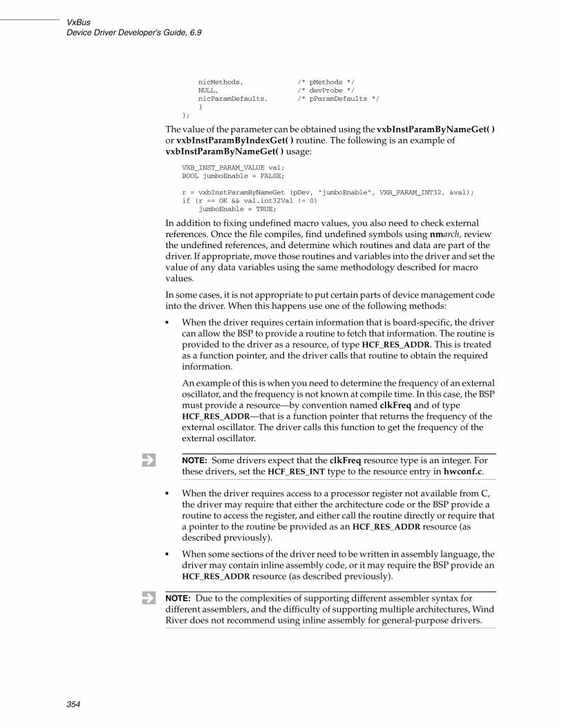
VxBusDevice Driver Developer's Guide, 6.9
354
nicMethods, /* pMethods */NULL, /* devProbe */nicParamDefaults, /* pParamDefaults */}
};
The value of the parameter can be obtained using the vxbInstParamByNameGet( ) or vxbInstParamByIndexGet( ) routine. The following is an example of vxbInstParamByNameGet( ) usage:
VXB_INST_PARAM_VALUE val;BOOL jumboEnable = FALSE;
r = vxbInstParamByNameGet (pDev, "jumboEnable", VXB_PARAM_INT32, &val);if (r == OK && val.int32Val != 0)
jumboEnable = TRUE;
In addition to fixing undefined macro values, you also need to check external references. Once the file compiles, find undefined symbols using nmarch, review the undefined references, and determine which routines and data are part of the driver. If appropriate, move those routines and variables into the driver and set the value of any data variables using the same methodology described for macro values.
In some cases, it is not appropriate to put certain parts of device management code into the driver. When this happens use one of the following methods:
■ When the driver requires certain information that is board-specific, the driver can allow the BSP to provide a routine to fetch that information. The routine is provided to the driver as a resource, of type HCF_RES_ADDR. This is treated as a function pointer, and the driver calls that routine to obtain the required information.
An example of this is when you need to determine the frequency of an external oscillator, and the frequency is not known at compile time. In this case, the BSP must provide a resource—by convention named clkFreq and of type HCF_RES_ADDR—that is a function pointer that returns the frequency of the external oscillator. The driver calls this function to get the frequency of the external oscillator.
■ When the driver requires access to a processor register not available from C, the driver may require that either the architecture code or the BSP provide a routine to access the register, and either call the routine directly or require that a pointer to the routine be provided as an HCF_RES_ADDR resource (as described previously).
■ When some sections of the driver need to be written in assembly language, the driver may contain inline assembly code, or it may require the BSP provide an HCF_RES_ADDR resource (as described previously).
NOTE: Some drivers expect that the clkFreq resource type is an integer. For these drivers, set the HCF_RES_INT type to the resource entry in hwconf.c.
NOTE: Due to the complexities of supporting different assembler syntax for different assemblers, and the difficulty of supporting multiple architectures, Wind River does not recommend using inline assembly for general-purpose drivers.

20 Migrating to VxBus20.3 Porting an Existing VxWorks Driver to VxBus
355
20.3.10 Converting Register Access in Existing Code
Most device drivers must access device registers. Often, drivers or BSPs provide their own custom register access routines for this purpose. These routines are designed to internally deal with issues such as I/O synchronization and byte order conversion. The problem with this approach is that it results in frequent code duplication. In some cases, it also causes inconsistency and conflicts between drivers and BSPs which can make porting a driver between BSPs and architectures difficult.
VxBus provides a consistent register access mechanism that handles byte-ordering, synchronization, and certain other common register manipulation issues. The routines are described in the hardware access section of 3. Device Driver Fundamentals.
Use of these routines is required in order for your driver to be portable across multiple boards or CPU types.
20.3.11 Removing Global Variables
One of the important goals of a generic driver is that it support multiple devices of the same type. Earlier in the development process, you may have chosen to create global variables specific to an instance (that is, a given device and driver paired together). Also, the existing driver you based your development on may have used global variables, perhaps in an array in order to support several devices. These global variables should be removed.
In VxBus, the main identification of a device is the VXB_DEVICE_ID. The structure that the VXB_DEVICE_ID points to contains a field for pDrvCtrl. pDrvCtrl is owned by the driver and can be used for any purpose. Most drivers define a structure that contains all instance-specific information.
During initialization, this structure is allocated using hwMemAlloc( ) (if the structure is allocated in initialization phase 1), filled in with the data, and a pointer to the structure is saved in the pDrvCtrl field. Later, when the driver is called for any reason, the VXB_DEVICE_ID is passed as a parameter, from which the driver can extract the pDrvCtrl field to get access to the instance-specific data.
In many cases, it is necessary to rewrite the prototype of some routines to pass pDrvCtrl or VXB_DEVICE_ID as a parameter. This allows each routine within the driver to have access to the information about an instance so that the routines do not need to rely on global variables.

VxBusDevice Driver Developer's Guide, 6.9
356

357
21Migrating to IPNET-Native Drivers
21.1 Introduction 357
21.2 Converting an Existing END Driver to an IPNET-Native Driver 358
21.3 Updating the Driver to use IPNET-Native Infrastructure 358
21.4 Updating Driver Routines 364
21.5 Building, Integrating, and Testing Your Driver 379
21.1 Introduction
This chapter provides a brief overview of the differences between traditional M_BLK-style network drivers and IPNET-native drivers. It also describes how to migrate an existing VxBus network driver to a VxBus IPNET-native network driver. This chapter presents this process as a series of steps that support the migration checklist provided in C. IPNET-Native Migration Checklist. The steps fall into three basic categories:
■ Updating your driver to use the IPNET-native driver infrastructure and driver model.
■ Updating various driver routines to support the new driver.
■ Building, integrating, and testing the new driver with VxWorks.
Before you begin, you should note that this migration information supplements the IPNET-native driver information provided in 11. Network Drivers. Be sure that you are familiar with that chapter, as well as the general VxBus documentation (see 3. Device Driver Fundamentals), before beginning your migration.
NOTE: This release of VxWorks includes IPNET-native versions of the etsec, gei, and tsec network drivers. If you have a custom version of one of these drivers (VxBus-enabled), you can use the information in this chapter as well as the checklist in C. IPNET-Native Migration Checklist to migrate your driver. These resources are also useful for migrating other VxBus-enabled network drivers (custom or Wind River-supplied).

VxBusDevice Driver Developer's Guide, 6.9
358
21.2 Converting an Existing END Driver to an IPNET-Native Driver
Most VxWorks network drivers (also referred to as network drivers or MAC drivers or—in earlier releases of VxWorks—END drivers) are based on the M_BLK, CL_BLK, and cluster packet model used by the Wind River Network Stack prior to VxWorks 6.5. However, since VxWorks 6.5, the network stack uses a new code base with a different packet model. The new model is based on the Ipcom_pkt control structure (with an attached packet buffer). To work with the traditional M_BLK-oriented network drivers, each packet sent by the stack in the form of an Ipcom_pkt must be wrapped as an M_BLK/CL_BLK packet before being delivered to the MUX, and each packet received by a network driver, described as an M_BLK/CL_BLK/cluster tuple, must be wrapped with an Ipcom_pkt if it is destined for the Wind River Network Stack.
To avoid the overhead of this packet format translation, and to address certain other issues, VxWorks 6.7 introduces a new network driver model (the IPNET-native driver model, sometimes referred to as END2) and corresponding changes in the MUX and the network stack. IPNET-native drivers, and new MUX2 routines like mux2Send( ), work natively with the Ipcom_pkt packet format used by the network stack. Thus, when such drivers deliver received packets to the IP stack, or accept packets from the IP stack for transmission, there is no packet format conversion overhead.
The IPNET-native system maintains backwards compatibility with existing M_BLK-oriented network drivers and protocols, through wrapper code that is used when required to convert between packet formats. This wrapper code incurs minimal performance overhead when the network stack exchanges packets with a traditional M_BLK-oriented driver, because this same packet translation is necessary in the previous MUX architecture (of VxWorks 6.5 and VxWorks 6.6) as well. M_BLK-oriented protocols bound to traditional drivers do not require packet conversion and, hence, do not use the translation wrappers. An M_BLK-oriented protocol that binds to a new IPNET-native style driver requires packet translation wrappers, and is at a performance disadvantage relative to the same M_BLK-oriented protocol using a traditional driver that uses M_BLK packets natively.
The following sections give a step-by-step process for converting an existing VxBus network driver to an IPNET-native VxBus network driver that uses Ipcom_pkt packets. If you are doing such a conversion, it is a good idea to compare the M_BLK-style and IPNET-native versions of a driver that has already been converted by Wind River, in addition to reading the material in this section. While the conversion is not purely mechanical, it is generally straightforward. However, you should note that some unusual drivers or highly-customized drivers may have additional conversion issues not covered here.
21.3 Updating the Driver to use IPNET-Native Infrastructure
The first steps of the migration process involving renaming and revising the driver itself to use the IPNET-native naming conventions and infrastructure. Once this process is complete, you can move on to updating your driver routines.

21 Migrating to IPNET-Native Drivers21.3 Updating the Driver to use IPNET-Native Infrastructure
359
Step 1: Copy, Relocate, and Rename the Existing Driver Source Files
Wind River provides C source files (.c files) for traditional VxBus network drivers in the source tree in the following location:
installDir/vxworks-6.x/target/src/hwif/end/
Header files for traditional drivers are located at:
installDir/vxworks-6.x/target/src/hwif/h/end/
IPNET-native drivers and their headers are located at:
installDir/vxworks-6.x/target/src/hwif/end2/
and
installDir/vxworks-6.x/target/src/hwif/h/end2/
respectively.
Therefore, start your driver conversion by copying the existing driver .c file from hwif/end/ to hwif/end2/, and the .h file from hwif/h/end/ to hwif/h/end2/. In the process, rename the driver files according to the following rules:
■ Change end to end2 in the .c and .h filenames.
■ If the existing name does not follow the format vxbDeviceEnd.c or vxbDeviceEnd.h, convert the new name to that format (recommended).
For example:
installDir/vxworks-6.x/target/src/hwif/end/vxbEtsecEnd.c
installDir/vxworks-6.x/target/src/hwif/h/end/vxbEtsecEnd.h
become
installDir/vxworks-6.x/target/src/hwif/end2/vxbEtsecEnd2.c
installDir/vxworks-6.x/target/src/hwif/h/end2/vxbEtsecEnd2.h
and
installDir/vxworks-6.x/target/src/hwif/end/gei825xxVxbEnd.c
installDir/vxworks-6.x/target/src/hwif/h/end/gei825xxVxbEnd.h
become
installDir/vxworks-6.x/target/src/hwif/end2/vxbGei825xxEnd2.c
installDir/vxworks-6.x/target/src/hwif/h/end2/vxbGei825xxEnd2.h
Edit the relocated and renamed copies to update any references to the old file names or locations within the source files.
These references include:
■ The title line comments of the files.
■ The #include of the driver header file from the driver .c file.
NOTE: The gei name change illustrates the conversion to the preferred vxbDeviceEnd2.x naming convention.

VxBusDevice Driver Developer's Guide, 6.9
360
■ The header file macro protecting against multiple inclusion.
■ Any references to the file names or locations in comments or documentation.
Step 2: Add a Makefile Fragment (.mk) for the Driver
The following makefile is used to build IPNET-native drivers:
installDir/vxworks-6.x/target/src/hwif/end2/Makefile
This file supports adding a new driver without modifying the existing makefile. The makefile includes any auxiliary driver-supplied makefile fragments (files in the same directory ending in the extension .mk) automatically. This helps prevent conflicts when applying patches from Wind River. The driver must supply a makefile fragment ending with the extension .mk in the following directory:
installDir/vxworks-6.x/target/src/hwif/end2
Conventionally, the name of this file is just the driver source file name with the .c extension replaced by .mk. The make file fragment is simple. For example, the fragment for the IPNET-native gei driver, vxbGei825xxEnd2.mk, contains only the following lines:
DOC_FILES += vxbGei825xxEnd2.c OBJS_COMMON += vxbGei825xxEnd2.o
This means to add the driver source file to the list of files used to generate the reference manual, and to add the driver object module to the set of objects built for all architectures. In contrast, the makefile fragment vxbTsecEnd2.mk for the tsec driver, which is built only for CPU=PPC32, contains the following:
DOC_FILES += vxbTsecEnd2.cOBJS_PPC32 += vxbTsecEnd2.o
Step 3: Rename the Driver Registration Routine
VxBus network drivers usually provide only a single globally visible symbol, which is the driver registration routine that informs VxBus of the driver's existence, and (in some cases) what devices it can control. To allow linking either the traditional or the IPNET-native version of a driver into the VxWorks image in a controlled fashion, the driver registration routine name must be different between the two versions. Change the driver registration routine name as indicated by the examples in Table 21-1.
Step 4: Change {muxDevConnect}( ) to {mux2DevConnect}( )
The MUX connection method of an IPNET-native driver must presently be called at a later point in the boot sequence than that of a traditional M_BLK-style driver. To accomplish this, a new method, {mux2DevConnect}( ) is called for IPNET-native drivers, rather than using {muxDevConnect}( ). In the driver's static device methods table, change the method name muxDevConnect to mux2DevConnect. The same driver routine, unchanged, is used for both methods. The following is an example for the etsec driver:
Table 21-1 Driver Registration Routine Examples
Name (Traditional Drivers) New Name (IPNET-Native Drivers)
etsecRegister( ) etsecEnd2Register( )
geiRegister( ) geiEnd2Register( )

21 Migrating to IPNET-Native Drivers21.3 Updating the Driver to use IPNET-Native Infrastructure
361
LOCAL struct vxbDeviceMethod etsecMethods[] ={DEVMETHOD(miiRead, etsecPhyRead),DEVMETHOD(miiWrite, etsecPhyWrite),DEVMETHOD(miiMediaUpdate, etsecLinkUpdate),DEVMETHOD(muxDevConnect, etsecMuxConnect),DEVMETHOD(vxbDrvUnlink, etsecInstUnlink),{ 0, 0 }};
Becomes:
LOCAL struct vxbDeviceMethod etsecMethods[] ={DEVMETHOD(miiRead, etsecPhyRead),DEVMETHOD(miiWrite, etsecPhyWrite),DEVMETHOD(miiMediaUpdate, etsecLinkUpdate),DEVMETHOD(mux2DevConnect, etsecMuxConnect),DEVMETHOD(vxbDrvUnlink, etsecInstUnlink),{ 0, 0 }};
Step 5: Change Included Header Files
An IPNET-native driver does not need to concern itself with the M_BLK, CL_BLK, and cluster form of packet buffers and pools, but it does need to know the Ipcom_pkt type and related APIs. Usually, the following set of IP stack header files is sufficient for an IPNET-native Ethernet driver:
#define IPCOM_SKIP_NATIVE_SOCK_API#include <ipcom_vxworks.h>#include <ipcom_clib.h>#include <vxmux_pkt.h>#include <ipnet_eth.h>
Step 6: Adjust the NET_FUNCS Structure
You must change the NET_FUNCS structure variable defined by the driver to an END2_NET_FUNCS structure (which contains a NET_FUNCS as its first element). The END2_NET_FUNCS and NET_FUNCS types are defined in:
installDir/vxworks-6.x/target/h/end.h
When modifying the variable definition, set the formAddress, packetDataGet, and addrGet members of the NET_FUNCS structure to NULL. The Ethernet versions of these routines—endEtherAddressForm( ), endEtherPacketDataGet( ), and endEtherPacketAddrGet( )—are implemented in endEtherHdr.c, and are used only to support M_BLK-oriented protocols. For scalability reasons, your IPNET-native driver should not refer directly to the endEtherHdr.c routines. Instead, the driver load routine sets these entries from function pointers. For more information, see Step 11:Change the Load Routine, p.364.
Because the prototypes of the driver send, polled send, and polled receive routines for an IPNET-native driver do not match those in the NET_FUNCS structure, casts are needed to avoid compiler warnings. The END_MUXSEND_RTN and END_POLLRCV_RTN types used for the cast are defined in end.h.
The following is an example for the vxbEtsecEnd2 driver:
LOCAL NET_FUNCS etsecNetFuncs ={etsecEndStart, /* start func. */etsecEndStop, /* stop func. */etsecEndUnload, /* unload func. */etsecEndIoctl, /* ioctl func. */etsecEndSend, /* send func. */

VxBusDevice Driver Developer's Guide, 6.9
362
etsecEndMCastAddrAdd, /* multicast add func. */etsecEndMCastAddrDel, /* multicast delete func. */etsecEndMCastAddrGet, /* multicast get fun. */etsecEndPollSend, /* polling send func. */etsecEndPollReceive, /* polling receive func. */endEtherAddressForm, /* put address info into a NET_BUFFER */endEtherPacketDataGet, /* get pointer to data in NET_BUFFER */endEtherPacketAddrGet /* Get packet addresses */};
Becomes:
LOCAL END2_NET_FUNCS etsecNetFuncs = {{etsecEndStart, /* start func. */etsecEndStop, /* stop func. */etsecEndUnload, /* unload func. */etsecEndIoctl, /* ioctl func. */(END_MUXSEND_RTN)etsecEndSend, /* send func. */etsecEndMCastAddrAdd, /* multicast add func. */etsecEndMCastAddrDel, /* multicast delete func. */etsecEndMCastAddrGet, /* multicast get fun. */(END_MUXSEND_RTN)etsecEndPollSend, /* polling send func. */(END_POLLRCV_RTN)etsecEndPollReceive, /* polling receive func. */NULL, /* endEtherAddressForm, /@ put address info into NET_BUFFER */NULL, /* endEtherPacketDataGet, /@ get pointer to data in NET_BUFFER */NULL /* endEtherPacketAddrGet /@ Get packet addresses */},NULL /* llhiComplete; NULL -> ethernet */};
After the NET_FUNCS member, the END2_NET_FUNCS structure contains (at present) one additional member:
void (*llhiComplete) (struct Ipcom_pkt_struct * pkt, LL_HDR_INFO * llhi);
This member is used by certain parts of the MUX wrapper code for muxBind( ) protocols over IPNET-native devices to parse the header in an Ipcom_pkt, initializing some fields of LL_HDR_INFO structure that cannot be determined fully from the Ipcom_pkt delivered to the wrapper receive routine. Drivers for Ethernet devices (and other devices that share the Ethernet header format) can set this member to NULL, indicating that muxOverEnd2Receive( ) should assume an Ethernet header. Drivers for devices with different header formats must provide an llhiComplete( ) routine that sets at least the destAddrOffset, destSize, srcAddrOffset, and srcSize members of the LL_HDR_INFO structure pointed to by the second argument to the routine, appropriate to the header in the packet identified by the first argument.1
Step 7: Replace END_TX_SEM_TAKE with END2_TX_SEM_TAKE
Throughout the driver, replace END_TX_SEM_TAKE with END2_TX_SEM_TAKE. At present, END2_TX_SEM_TAKE behaves identically to END_TX_SEM_TAKE. However, this may change in a future release and there may be differences in some restricted cases.
Step 8: Replace END_TX_SEM_GIVE with END2_TX_SEM_GIVE
Throughout the driver, replace END_TX_SEM_GIVE with END2_TX_SEM_GIVE. At present, END2_TX_SEM_GIVE behaves identically to END_TX_SEM_GIVE.
1. The Wind River Network Stack may require additional changes to support non-Ethernet devices. For more information, see the Wind River Network Stack documentation.
NOTE: This step is optional but recommended for this release.

21 Migrating to IPNET-Native Drivers21.3 Updating the Driver to use IPNET-Native Infrastructure
363
However, this may change in a future release and there may be differences in some restricted cases.
Step 9: Change Signatures for Driver Routines that Use M_BLK or M_BLK_ID
You must change the signatures for the driver routines that involve M_BLK or M_BLK_ID. Change the prototypes of the driver's send routine, polled send routine, and polled receive routine to the form used by IPNET-native drivers. See the following example for the tsec driver:
LOCAL int tsecEndSend (END_OBJ *, M_BLK_ID);LOCAL int tsecEndEncap (TSEC_DRV_CTRL *, M_BLK_ID);LOCAL STATUS tsecEndPollSend (END_OBJ *, M_BLK_ID);LOCAL int tsecEndPollReceive (END_OBJ *, M_BLK_ID);
Becomes:
LOCAL int tsecEndSend (END_OBJ *, Ipcom_pkt *);LOCAL int tsecEndEncap (TSEC_DRV_CTRL *, Ipcom_pkt *);LOCAL STATUS tsecEndPollSend (END_OBJ *, Ipcom_pkt *);LOCAL int tsecEndPollReceive (END_OBJ *, Ipcom_pkt *);
Some drivers provide additional routines with M_BLK * or M_BLK_ID arguments. If this is the case for your driver, change those routines as well. At this point, you can change the prototype in any forward declaration and in the routine definition. Later in the process you can modify the function bodies of these routines (discussed later in this section).
When modifying any declarations that provide argument names, change argument names that suggest an M_BLK_ID (for example, pMblk) to names that suggest Ipcom_pkt pointers (for example, pkt).
Step 10: Revise Driver Control Structure Members that use M_BLK
Eventually, all instances of M_BLK_ID or M_BLK * in the driver .c and .h files should be replaced with Ipcom_pkt * (or struct Ipcom_pkt_struct *), or else removed. However, at this point in the process, it is sufficient to retype and rename members of the driver control structure (defined in the driver header file) that involve M_BLK pointers (or, equivalently, M_BLK_ID).
For example, the following members of the tsec driver are changed as follows:
M_BLK_ID tsecPollBuf;...
M_BLK_ID tsecRxMblk[TSEC_RX_DESC_CNT];M_BLK_ID tsecTxMblk[TSEC_TX_DESC_CNT];
Becomes:
struct Ipcom_pkt_struct * tsecRxPkt[TSEC_RX_DESC_CNT];struct Ipcom_pkt_struct * tsecTxPkt[TSEC_TX_DESC_CNT];
Many other drivers use vxbDmaBufLib, and so maintain additional associated arrays of VXB_DMA_MAP_ID for receive and transmit packet data buffers; as well as a single VXB_DMA_TAG_ID for packet buffers. These members do not need retyping, but you can rename them if they mention Mblk. For example:
VXB_DMA_TAG_ID geiMblkTag;VXB_DMA_MAP_ID geiRxMblkMap[GEI_RX_DESC_CNT];VXB_DMA_MAP_ID geiTxMblkMap[GEI_TX_DESC_CNT];
NOTE: This step is optional but recommended for this release.

VxBusDevice Driver Developer's Guide, 6.9
364
Becomes:
VXB_DMA_TAG_ID geiPktTag;VXB_DMA_MAP_ID geiRxPktMap[GEI_RX_DESC_CNT];VXB_DMA_MAP_ID geiTxPktMap[GEI_TX_DESC_CNT];
You should also add an incomplete declaration at file scope in the header file as follows:
struct Ipcom_pkt_struct;
This establishes the structure tag in case the header file is ever included without the ipcom include paths visible.2
Some drivers that support devices with multiple receive or transmit queues in hardware may have more complicated arrays representing the M_BLK packets associated with the different queues. Change these accordingly.
For each changed member name, go through the driver source and replace the old member name with the new name. (You may do this all at once, or as you work through the individual driver routines.)
21.4 Updating Driver Routines
The steps discussed in this section involve updating and changing your driver routines to support the new IPNET-native driver.
Step 11: Change the Load Routine
An Ethernet driver (or more generally, a driver for a device using the Ethernet header format) should include the following boilerplate code at the start of its load routine (renaming the END2_NET_FUNCS as appropriate for the driver):
/** Use the endLib functions to support legacy protocols, if* available.*/
if (etsecNetFuncs.funcs.formAddress == NULL)etsecNetFuncs.funcs.formAddress = _func_endEtherAddressForm;
if (etsecNetFuncs.funcs.packetDataGet == NULL)etsecNetFuncs.funcs.packetDataGet = _func_endEtherPacketDataGet;
if (etsecNetFuncs.funcs.addrGet == NULL)etsecNetFuncs.funcs.addrGet = _func_endEtherPacketAddrGet;
2. Duplicate typedefs (even consistent duplicate typedefs) are illegal, and some compilers enforce this rule. Because the ipcom_pkt.h header file that defines Ipcom_pkt is already included (indirectly) when the driver source file includes the driver header, adding typedef struct Ipcom_pkt_struct Ipcom_pkt; to the driver header may generate a build error.
NOTE: You should be careful of false cognates where the symbol being renamed is also used for something other than a driver control structure member. Also, be careful that the new name is not already in use for some other purpose.

21 Migrating to IPNET-Native Drivers21.4 Updating Driver Routines
365
A bit later in the load routine, after the driver control structure (for example, ETSEC_DRV_CTRL) pointer is available, an Ethernet driver should add the following (renaming the END_OBJ member as appropriate):
pDrvCtrl->etsecEndObj.hdrParse = end2EtherHdrParse;pDrvCtrl->etsecEndObj.formLinkHdr = end2EtherIIFormLinkHdr;
The hdrParse( ) routine is called by mux2Receive( )—the native receive routine for IPNET-native drivers—to extract the network service offset and network service type from a received Ipcom_pkt packet. The hdrParse function pointer can also be replaced by the MUX_L2 VLAN code with a more complicated routine that performs VLAN classification and filtering.3
Non-Ethernet drivers must provide their own version of the hdrParse( ) routine. For example:
int (*hdrParse) (struct end_object * pEnd, struct Ipcom_pkt_struct * pkt);
The hdrParse( ) routine should return either the network service type (in host byte order), or should return -1. If hdrParse( ) returns a negative value, the caller discards (frees) the packet. If hdrParse( ) returns a non-negative value for the network service type, it should first set the following:
pkt->ipstart = pkt->start + hdrlen;pkt->net_svc = netsvc;
where netsvc is the network service type to be returned, and hdrlen is the network service offset, the byte offset from the start of the packet's link header to the start of the network layer header.
The formLinkHdr( ) function pointer has the following type:
typedef int (* END2_FORM_LINKHDR_RTN) (END_OBJ * pEnd, Ipcom_pkt * pkt,UINT8 * dstAddr, UINT8 * srcAddr,UINT16 netType);
This function pointer is intended to either return the size in bytes of a link header for the device (when pkt is IP_NULL), or to actually prepend a link header to the start of the packet specified by a non-IP_NULL pkt pointer. dstAddr and srcAddr point to buffers containing the wire-format destination and source addresses to be used in the link header, and netTupe is the packet's network service type (for example, ethertype) in network byte order. If pkt is not IP_NULL and the packet contains insufficient space at the start to prepend the link header, the routine returns ERROR. Otherwise, the routine returns the size in bytes of the link header.
At present, this function pointer is only used by muxTkBind( ) protocols over IPNET-native devices (for example, for the WDB agent); but it could potentially be used by any protocol to construct a link header on a packet destined for an IPNET-native device. The network stack does not presently use the formLinkHdr( ) routine.
A traditional VxBus driver load routine creates a private linkBufPool-style buffer pool by calling code similar to the following (from the gei driver):
3. MUX Layer 2 library (muxL2Lib) functionality is not supported for IPNET-native drivers in this release.

VxBusDevice Driver Developer's Guide, 6.9
366
/* Allocate a buffer pool */
if (pDrvCtrl->geiMaxMtu == GEI_JUMBO_MTU)r = endPoolJumboCreate (3 * GEI_RX_DESC_CNT,
&pDrvCtrl->geiEndObj.pNetPool);else
r = endPoolCreate (3 * GEI_RX_DESC_CNT, &pDrvCtrl->geiEndObj.pNetPool);
if (r == ERROR){logMsg("%s%d: pool creation failed\n", (int)GEI_NAME,
pDev->unitNumber, 0, 0, 0, 0);return (NULL);}
You must remove this code for IPNET-native drivers. Instead, all IPNET-native drivers, Ethernet or not, should add the following line to the load routine (replacing gei as necessary for your driver):
pDrvCtrl->geiEndObj.pNetPool = _end2_linkBufPool;
This code supports use by the WDB agent or other M_BLK-oriented protocols that try to allocate tuples out of the device netBufLib-style pool. For more information, see the polled mode information for IPNET-native drivers in 11. Network Drivers.
M_BLK-oriented driver load routines typically allocate an M_BLK tuple from their network buffer pools for use in polled mode sends. For IPNET-native drivers, such a packet buffer is instead allocated out of the shared packet pool. Therefore, it is preferable to hold the buffer only while the device is up; that is, allocate the buffer in the driver start routine, and free it in the driver stop routine. Also, for an IPNET-native driver, the packet buffer is held in a member of the END_OBJ structure, not the driver-specific extension, so that the MUX wrapper routines supporting polled mode use of an IPNET-native device by the M_BLK-oriented WDB agent can access the buffer.
A pointer to NET_FUNCS embedded in END2_NET_FUNCS must be passed to the END_OBJ_INIT( ) macro, which is called from the driver load routine. In the vxbEtsecEnd2 driver, &etsecNetFuncs.funcs is passed as an argument when necessary rather than just &etsecNetFuncs. Also, in the END_OBJ_INIT( ) call, change the driver description string to indicate an IPNET-native (END2) driver rather than an traditional M_BLK-style (END) driver.
Step 12: Change the Unload Routine
The following updates are required in the driver unload routine:
■ You must remove the code that frees the transmit polled-mode buffer. For IPNET-native drivers, this buffer is freed in the stop routine.
■ You must remove the code that calls endPoolDestroy( ) to destroy the drivers’ M_BLK tuple pool. IPNET-native drivers use the shared packet pool instead.
Step 13: Change the Start Routine
In the driver's start routine, after checking that the device is not already up, add code to allocate an Ipcom_pkt for use in the polled mode send routine. The corresponding M_BLK tuple allocation is done in the load routine for an M_BLK-style driver, but you should not hold the polled-mode packet when the device is down, because it typically comes from the shared packet pool. You should also note that the packet reference is kept in the pollPkt member of END_OBJ, so that wrapper routines can access it.
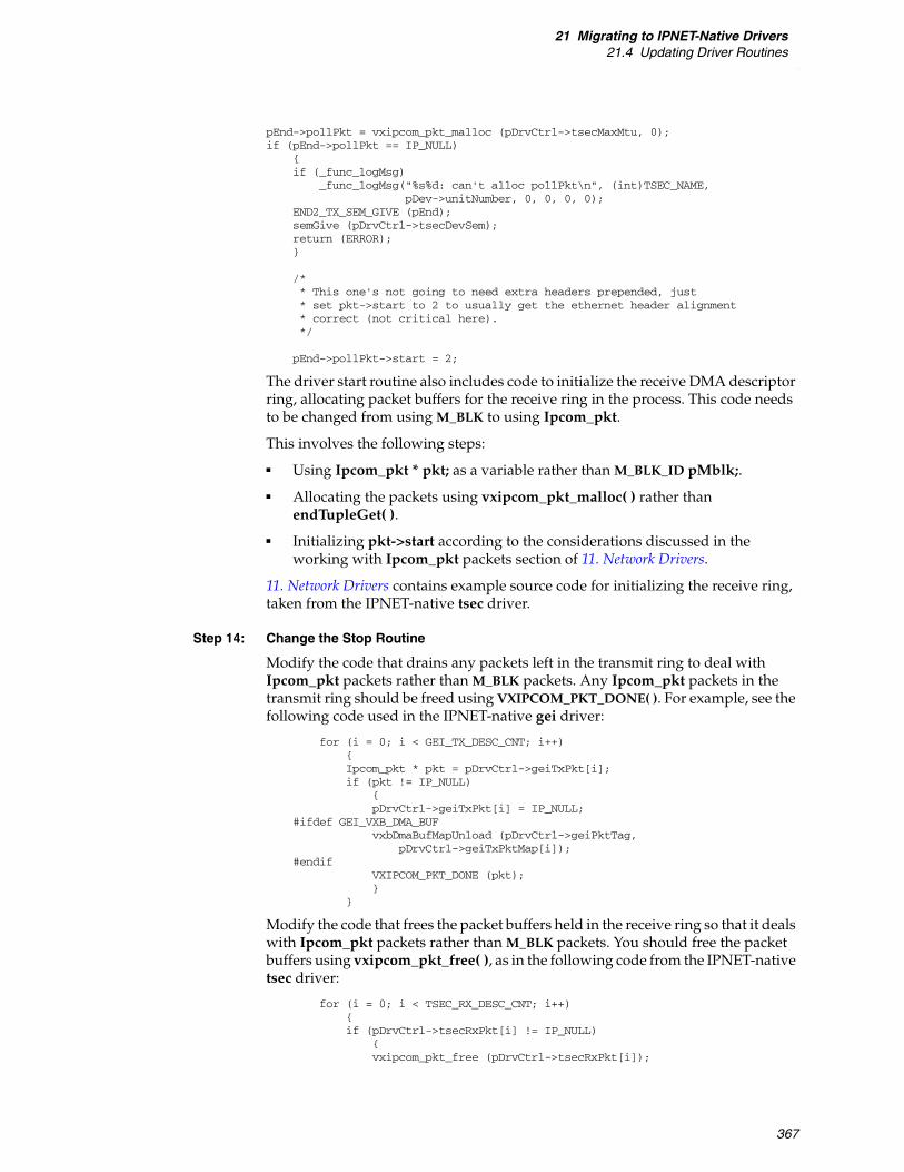
21 Migrating to IPNET-Native Drivers21.4 Updating Driver Routines
367
pEnd->pollPkt = vxipcom_pkt_malloc (pDrvCtrl->tsecMaxMtu, 0);if (pEnd->pollPkt == IP_NULL)
{if (_func_logMsg)
_func_logMsg("%s%d: can't alloc pollPkt\n", (int)TSEC_NAME,pDev->unitNumber, 0, 0, 0, 0);
END2_TX_SEM_GIVE (pEnd);semGive (pDrvCtrl->tsecDevSem);return (ERROR);}
/** This one's not going to need extra headers prepended, just* set pkt->start to 2 to usually get the ethernet header alignment* correct (not critical here).*/
pEnd->pollPkt->start = 2;
The driver start routine also includes code to initialize the receive DMA descriptor ring, allocating packet buffers for the receive ring in the process. This code needs to be changed from using M_BLK to using Ipcom_pkt.
This involves the following steps:
■ Using Ipcom_pkt * pkt; as a variable rather than M_BLK_ID pMblk;.
■ Allocating the packets using vxipcom_pkt_malloc( ) rather than endTupleGet( ).
■ Initializing pkt->start according to the considerations discussed in the working with Ipcom_pkt packets section of 11. Network Drivers.
11. Network Drivers contains example source code for initializing the receive ring, taken from the IPNET-native tsec driver.
Step 14: Change the Stop Routine
Modify the code that drains any packets left in the transmit ring to deal with Ipcom_pkt packets rather than M_BLK packets. Any Ipcom_pkt packets in the transmit ring should be freed using VXIPCOM_PKT_DONE( ). For example, see the following code used in the IPNET-native gei driver:
for (i = 0; i < GEI_TX_DESC_CNT; i++){Ipcom_pkt * pkt = pDrvCtrl->geiTxPkt[i];if (pkt != IP_NULL)
{pDrvCtrl->geiTxPkt[i] = IP_NULL;
#ifdef GEI_VXB_DMA_BUFvxbDmaBufMapUnload (pDrvCtrl->geiPktTag,
pDrvCtrl->geiTxPktMap[i]);#endif
VXIPCOM_PKT_DONE (pkt);}
}
Modify the code that frees the packet buffers held in the receive ring so that it deals with Ipcom_pkt packets rather than M_BLK packets. You should free the packet buffers using vxipcom_pkt_free( ), as in the following code from the IPNET-native tsec driver:
for (i = 0; i < TSEC_RX_DESC_CNT; i++){if (pDrvCtrl->tsecRxPkt[i] != IP_NULL)
{vxipcom_pkt_free (pDrvCtrl->tsecRxPkt[i]);

VxBusDevice Driver Developer's Guide, 6.9
368
pDrvCtrl->tsecRxPkt[i] = IP_NULL;}
}
Add code that frees the transmit polled send utility buffer as follows:
vxipcom_pkt_free (pDrvCtrl->tsecEndObj.pollPkt);pDrvCtrl->tsecEndObj.pollPkt = IP_NULL;
Step 15: Change the Send Routine
A common algorithm for the driver's send routine is the following:
1. The driver takes the instance's transmit mutex semaphore.
2. The driver checks a flag (maintained by the {miiMediaUpdate}( ) method) indicating whether the link is currently active. If it is not active, the driver goes to the blocked label.
3. (Optional) If the number of free transmit descriptors is less than some threshold value, the driver can call the transmit cleanup routine to attempt to free up some transmit descriptors.
4. The driver checks for free transmit DMA descriptors. If there are not at least some minimum number free (typically 1), the driver goes to the blocked label.
5. The driver calls the transmit encapsulation routine to attempt to add the packet to the device transmit ring. This can fail for a multi-segment packet if there are more segments than available free transmit descriptors, in which case the encapsulation routine cleans up and returns ENOSPC. Otherwise, the encapsulation routine returns OK.
6. If the encapsulation routine returns ENOSPC on the first try, the driver attempts to coalesce the multi-segment packet into a single segment packet. This involves attempting to allocate a new packet, copying the data from the original multi-segment packet into the new packet, also copying any needed packet header information, encapsulating the new packet, and freeing the original.
7. If the encapsulation is ultimately successful, the driver issues a transmit command to the device if necessary, gives up the transmit mutex semaphore, and returns OK.
8. If the driver remains blocked, it sets an instance-specific flag to indicate that a transmit stall has occurred. The driver gives up the transmit mutex semaphore and returns -IP_ERRNO_EWOULDBLOCK (unlike a traditional M_BLK driver which returns END_ERR_BLOCK in this situation).
Note that if the send routine returns indicating a transmit stall, the caller maintains ownership of the packet, and can choose to attempt a retransmit later. The driver is responsible for making a call to muxTxRestart( ) later when more transmit descriptors are available.
The send routine must be modified to use Ipcom_pkt packets. This is straightforward, except possibly for the code that attempts to coalesce a multi-segment packet into a single segment packet. The code in the traditional gei (M_BLK-oriented) driver is as follows:
/** If geiEndEncap() returns ENOSPC, it means it ran out* of TX descriptors and couldn't encapsulate the whole* packet fragment chain. In that case, we need to* coalesce everything into a single buffer and try

21 Migrating to IPNET-Native Drivers21.4 Updating Driver Routines
369
* again. If any other error is returned, then something* went wrong, and we have to abort the transmission* entirely.*/
if (rval == ENOSPC){if ((pTmp = endPoolTupleGet (pDrvCtrl->geiEndObj.pNetPool)) == NULL)
goto blocked;pTmp->m_len = pTmp->m_pkthdr.len =
netMblkToBufCopy (pMblk, mtod(pTmp, char *), NULL);pTmp->m_flags = pMblk->m_flags;pTmp->m_pkthdr.csum_flags = pMblk->m_pkthdr.csum_flags;pTmp->m_pkthdr.csum_data = pMblk->m_pkthdr.csum_data;pTmp->m_pkthdr.vlan = pMblk->m_pkthdr.vlan;CSUM_IP_HDRLEN(pTmp) = CSUM_IP_HDRLEN(pMblk);
#ifdef CSUM_IPHDR_OFFSETCSUM_IPHDR_OFFSET(pTmp) = CSUM_IPHDR_OFFSET(pMblk);
#endif
/* Try transmission again, should succeed this time. */rval = geiEndEncap (pDrvCtrl, pTmp);if (rval == OK)
endPoolTupleFree (pMblk);else
endPoolTupleFree (pTmp);}
/* Issue transmit command */
CSR_WRITE_4(pDev, GEI_TDT, pDrvCtrl->geiTxProd);
if (rval != OK)goto blocked;
For the IPNET-native version of the etsec driver, this code is changed as follows:
/** If geiEndEncap() returns ENOSPC, it means it ran out* of TX descriptors and couldn't encapsulate the whole* packet fragment chain. In that case, we need to* coalesce everything into a single buffer and try* again. If any other error is returned, then something* went wrong, and we have to abort the transmission* entirely.*/
if (rval == ENOSPC){Ipcom_pkt * pTmp;Ip_u8 * buf;Ipcom_pkt * pkt2;
/* copy discontiguous info from pkt chain to pTmp... */if ((pTmp = vxipcom_pkt_malloc (pDrvCtrl->geiMaxMtu, 0))
== NULL)goto blocked;
pTmp->start = (((pTmp->maxlen - pDrvCtrl->geiMaxMtu) & ~0x3) -MAX_ETHER_LINKHDR);
buf = &pTmp->data[pTmp->start];for (pkt2 = pkt; pkt2 != IP_NULL; pkt2 = pkt->next_part)
{int len2 = pkt2->end - pkt2->start;bcopy ((caddr_t)&pkt2->data[pkt2->start], (caddr_t)buf, len2);buf += len2;}
pTmp->end = buf - pTmp->data;/* for checksum offload & vlan offload stuff */pTmp->flags = pkt->flags;pTmp->chk = pkt->chk;

VxBusDevice Driver Developer's Guide, 6.9
370
pTmp->ipstart = pTmp->start + (pkt->ipstart - pkt->start);pTmp->tlstart = pTmp->start + (pkt->tlstart - pkt->start);pTmp->link_cookie = pkt->link_cookie;
/* Try transmission again, should succeed this time. */rval = geiEndEncap (pDrvCtrl, pTmp);if (rval == OK)
VXIPCOM_PKT_DONE (pkt); /* hmm, not realy done in terms ofsend flow control ... */
elsevxipcom_pkt_free (pTmp);
}
if (rval != OK){GEI_STATS (txNospc++);goto blocked;}
/* Issue transmit command */
CSR_WRITE_4(pDev, GEI_TDT, pDrvCtrl->geiTxProd);
Step 16: Change the Transmit Encapsulation Routine
The transmit encapsulation routine is responsible for walking the chain of Ipcom_pkt or M_BLK structures that describe the packet, and programing device transmit DMA descriptors to prepare to transmit the (possibly segmented) packet data. In general, the conversion from M_BLK packets to Ipcom_pkt packets is straightforward. However, you should note the following:
■ Drivers that use vxbDmaBufLib must use vxbDmaBufMapIpcomLoad( ) in place of vxbDmaBufMapMblkLoad( ).
■ The checksum offload and VLAN tag insertion offload interface is different. For detailed information regarding the per-packet transmit offload interface used with IPNET-native drivers, see the per-packet transmit checksum offload interface section of 11. Network Drivers.
Step 17: Change the Transmit Cleanup Code
Some drivers—typically those that do some transmit cleanup work from their send routines— have a separate transmit cleanup routine that can be called from both the send routine and (possibly) the transmit cleanup handler job, with the transmit mutex semaphore already held. Other drivers do transmit cleanup work only from the transmit cleanup handler job. In this case, the transmit cleanup function is typically inlined in the handler job. However, the work done in the nominal transmit cleanup function is the same in either case, inlined or not. This code works through pending transmits recorded in the transmit DMA ring, and frees the packet buffers associated with entries for which transmission has completed. (For some drivers, the handler job code can also record error conditions and restart the transmitter if it has stopped due to an error.)
It is straightforward to convert the transmit cleanup function to use Ipcom_pkt packets rather than M_BLK packets. To do this, you must be sure that any packets from the transmit ring are freed with the following:
VXIPCOM_PKT_FREE (pkt);
Instead of:
endPoolTupleFree (pMblk);

21 Migrating to IPNET-Native Drivers21.4 Updating Driver Routines
371
The transmit cleanup handler job logic that controls the instance's transmit stalled flag and calls muxTxRestart( ) when this flag is cleared is identical between an M_BLK-oriented driver and an IPNET-native driver.
Step 18: Change the Receive Handler Routine
The changes to the receive handler routine include generic changes to use Ipcom_pkt rather than M_BLK, and more specifically, to use the IPNET-native per-packet checksum offload interface if the driver supports receive checksum offload. Note the following:
■ You must rename the M_BLK_ID variables. For example:
M_BLK_ID pMblk;M_BLK_ID pNewMblk;
Becomes:
Ipcom_pkt * pkt;Ipcom_pkt * newpkt;
■ You must allocate replacement packets using ipcom_pkt_malloc( ) rather than endPoolTupleGet( ). For example, the following code:
pNewMblk = endPoolTupleGet(pDrvCtrl->tsecEndObj.pNetPool);if (pNewMblk == NULL)
{...}
Becomes:
newpkt = vxipcom_pkt_malloc (pDrvCtrl->tsecMaxMtu, 0);if (newpkt == IP_NULL)
{...}
After allocating the replacement packet newpkt, you must initialize newpkt->start, taking special care for devices with receive buffer alignment restrictions. For information on initializing newpkt->start, see the working with Ipcom_pkt packets section 11. Network Drivers.
The following example is from the IPNET-native tsec driver:
/** newpkt->data is presently only guaranteed to be cache-line* aligned (32 bytes on the boards in question). Since TSEC_RX_ALIGN* is 64 bytes, we have to consider newpkt->data and newpkt->start* jointly; the address of the start of the packet data is their sum.** 'off' is the smallest offset from newpkt->data that has 64-byte* alignment.*/
off = (- (UINT32)newpkt->data) & (TSEC_RX_ALIGN - 1);
newpkt->start = off +((newpkt->maxlen - off - pDrvCtrl->tsecMaxMtu - MAX_ETHER_LINKHDR) &~(TSEC_RX_ALIGN - 1));
When using vxbDmaBufLib, the vxbDmaBufMapIpcomLoad( ) routine that replaces vxbDmaBufMapMblkLoad( ) requires that the packet's end offset be set appropriately. In the receive routine, you should set newpkt->end as follows:
newpkt->end = newpkt->maxlen;

VxBusDevice Driver Developer's Guide, 6.9
372
The code to exchange the received packet and the replacement packet requires name changes. For example:
pMblk = pDrvCtrl->tsecRxMblk[pDrvCtrl->tsecRxIdx];pDrvCtrl->tsecRxMblk[pDrvCtrl->tsecRxIdx] = pNewMblk;
Becomes:
pkt = pDrvCtrl->tsecRxPkt[pDrvCtrl->tsecRxIdx]; pDrvCtrl->tsecRxPkt[pDrvCtrl->tsecRxIdx] = newpkt;
You must change the code that records the received frame's length. For example, the following code:
/* Set the mBlk header up with the frame length. */
pMblk->m_len = pMblk->m_pkthdr.len = pDesc->bdLen - ETHER_CRC_LEN;pMblk->m_flags = M_PKTHDR|M_EXT;
Becomes:
/* Set the packet header up with the frame length. */
pkt->end = pkt->start + pDesc->bdLen - ETHER_CRC_LEN;
Note that there is no required analog for the statement setting pMblk->m_flags.
Change the code that sets the physical address of the replacement packet buffer in the receive DMA descriptor. For a driver that works on a single architecture with identity-mapped, cache-coherent buffers that are guaranteed visible to the device DMA engine, this process may only involve changing the following:
pDesc->bdAddr = mtod(pNewMblk, UINT32);
To:
pDesc->bdAddr = (UINT32)&newpkt->data[newpkt->start];
However, less restricted drivers may need to use vxbDmaBufMapLib to take care of cache coherency and address translation or bounce buffering issues. Apart from variable renaming, the only significant change is the use of vxbDmaBufMapIpcomLoad( ) instead of vxbDmaBufMapMblkLoad( ). For example:
vxbDmaBufMapMblkLoad (pDev, pDrvCtrl->geiMblkTag, pMap, pNewMblk, 0);
Becomes:
vxbDmaBufMapIpcomLoad (pDev, pDrvCtrl->geiPktTag, pMap, newpkt, 0);
The IPNET-native per-packet receive checksum offload interface is different from that for M_BLK-oriented drivers. Similarly, the offload interface for VLAN tag extraction is different. For drivers that support either of these types of offloading, adjust the code accordingly. For more information, see the per-packet transmit checksum offload interface section of 11. Network Drivers.
IPNET-native drivers should use the macro END2_RCV_RTN_CALL( ) in place of END_RCV_RTN_CALL( ) to deliver received packets to the MUX. For example:
END_RCV_RTN_CALL (&pDrvCtrl->geiEndObj, pMblk);
Becomes:
END2_RCV_RTN_CALL (&pDrvCtrl->geiEndObj, pkt);

21 Migrating to IPNET-Native Drivers21.4 Updating Driver Routines
373
Step 19: Change the ioctl( ) Routine
All IPNET-native drivers must support the EIOCGSTYLE ioctl( ) that identifies the driver as having style, END_STYLE_END2. The code is a simple additional case in the driver ioctl( ) routine switch statement. For example:
case EIOCGSTYLE:if (data == NULL)
error = EINVAL;else
*(int *)data = END_STYLE_END2;break;
To enter and exit polled mode, the WDB agent calls the EIOCPOLLSTART and EIOCPOLLSTOP ioctl( ) routines. These routines are typically called with interrupts locked out for the CPU and the system suspended—VxWorks kernel functions cannot safely be called under these conditions. Current drivers handle EIOCPOLLSTART by setting a flag indicating that polled mode has been entered, recording the device's current interrupt enable mask for later restoration during EIOCPOLLSTOP, disabling all device interrupts, and clearing the transmit ring.
Clearing the transmit ring means waiting for any transmits to complete and freeing—or remembering to free4—any packet buffers in the ring, so that the ring is empty before the EIOCPOLLSTART handler returns and is empty whenever the polled mode send routine is called.
The process of freeing any packets from the transmit ring must be changed to use Ipcom_pkt instead of M_BLK. As always, packets from the transmit ring should be freed using VXIPCOM_PKT_DONE( ).
Step 20: Change the Polled-Mode Send Routine
The polled send routine of an IPNET-native network driver has the following signature:
LOCAL int devEndPollSend(END_OBJ * pEnd,Ipcom_pkt * pkt);
The routine is expected to either transmit the packet and return OK, or else return EAGAIN if the packet cannot be sent immediately. The caller owns the packet both before and after the call, which implies that in the successful case, the polled send routine cannot return until the transmit is complete.
The driver can assume that it is never called with a multi-segment packet—that is, pkt->next_part is never IP_NULL and the driver can include an assertion to this effect. Although a hypothetical M_BLK-oriented network can call muxPollSend( )
4. Although current drivers free transmitted packets from the transmit ring in the EIOCPOLLSTART handler, this is not entirely safe to do because the code that is executed as a result of freeing the packets can involve VxWorks kernel operations that are not safe to perform with interrupts locked and the system suspended. In practice, problems rarely seem to arise from this, and there is presently no completely satisfactory alternative. This issue potentially affects only systems where system-mode debugging through the WDB agent (with the INCLUDE_WDB_COMM_END communication type) is taking place.
NOTE: The polled-mode send interface for a network driver is intended to support system mode debugging by the WDB agent. It is not a high-performance interface and it is not intended for general use.

VxBusDevice Driver Developer's Guide, 6.9
374
or muxTkPollSend( ) passing a multi-segment M_BLK chain for an IPNET-native driver, the MUX takes care of coalescing such a send into a single Ipcom_pkt buffer. This buffer is actually the pEnd->pollPkt packet buffer allocated by the driver's start routine. Whenever an M_BLK-oriented protocol (such as the WDB agent) does a polled send, pEnd->pollPkt is passed as the second argument to the polled send routine. The mux2PollSend( ) routine can also be used to perform a polled send of an unsegmented Ipcom_pkt packet. In this case, the arguments to the driver polled send routine are the same as those to mux2PollSend( ). However, no current VxWorks software uses mux2PollSend( ).
Converting the polled send routine to work with Ipcom_pkt packets instead of M_BLK is straightforward. However, you should note that because the input packet is always non-segmented, it should not be necessary to copy the packet data provided that the device does not have transmit data buffer alignment restrictions. If the device does have such restrictions, when the start routine allocates pEnd->pollPkt, it should also set pEnd->pollPkt->start such that &pEnd->pollPkt->data[pEnd->pollPkt->start] has an acceptable starting alignment for the device. When the polled send routine is passed pEnd->pollPkt, the routine knows that the packet data is already aligned correctly. When it is passed some other packet, it can copy the packet data into the pEnd->pollPkt buffer at the above location to ensure proper alignment.
Step 21: Change the Polled-Mode Receive Routine
The IPNET-native driver polled-mode receive routine is passed a pointer to a single-segment Ipcom_pkt packet pkt as its second argument. All of the buffer space between &pkt->data[pkt->start] and &pkt->data[pkt->maxlen] is available to copy received packets into. The caller is responsible for making the buffer large enough to accept the largest packet off of the wire, but the driver should check that the received packet fits in the available space, and if not, should drop the packet and return EAGAIN from the polled-mode receive routine. Otherwise, the driver copies the received packet data into the buffer starting at &pkt->data[pkt->start] and sets pkt->end so that the length of the packet is pkt->end minus pkt->start. Due to the check of available space, it should always be the case that pkt->end is less than pkt->maxlen.
NOTE: Currently, the MUX wrappers for muxPollSend( ) and muxTkPollSend( ) over an IPNET-native device do not support transmit checksum offload or VLAN tag insertion. However, only the WDB agent is expected to use these routines, and WDB does not attempt transmit checksum or VLAN offload. Consequently, it is not currently a requirement that IPNET-native drivers support transmit checksum offload or VLAN tag insertion offload in their polled-mode send routines.
NOTE: The polled-mode receive interface for a network driver is intended to support system mode debugging by the WDB agent. It is not a high-performance interface (it requires bulk packet data copying) and it is not intended for general use.

21 Migrating to IPNET-Native Drivers21.4 Updating Driver Routines
375
Step 22: Change Statistics Collection
All IPNET-native drivers are expected to support the polled-mode statistics interface. If an IPNET-native driver is based on an existing M_BLK-style driver that supports polled-mode statistics—that is, supports the EIOCGPOLLCONF and EIOCGPOLLSTATS ioctl( ) commands—no additional work is typically needed for the IPNET-native driver. However, if the original M_BLK-style driver uses the endM2Packet( ) routine to adjust statistics on a per-packet basis, its statistics collection must be modified because the endM2Packet( ) routine is M_BLK-based.
The polled-mode statistics collection interface is designed provide better performance with devices that support collecting statistics in hardware. Instead of attempting to maintain software statistics on a per-packet basis, as the endM2Packet( ) method does, devices that support polled-mode statistics are polled periodically (on the order of once per second; the driver chooses the polling rate), to collect statistics counts that have accumulated since the last poll.
Although the polled-mode interface is most natural and has the best performance when the actual device maintains packet statistics in hardware, the polled-mode interface can be used when the device does not maintain statistics. In this case, the driver collects statistics per-packet in software, accumulating them for the next time EIOCGPOLLSTATS is called to collect the statistics. This is generally more efficient than calling endM2Packet( ) for each packet sent or received because it avoids the function call overhead of endM2Packet( ).
To support polled mode statistics, a VxBus network driver needs to embed an END_IFDRVCONF and an END_IFCOUNTERS member in each instance's driver control structure. For example, in the etsec driver, this is done as follows:
END_IFDRVCONF etsecEndStatsConf;END_IFCOUNTERS etsecEndStatsCounters;
The types are defined in:
installDir/vxworks-6.x/target/h/end.h
They are defined as follows:
/** Definitions and structures for polled stats counters.*/
typedef unsigned long long endCounter;
typedef struct /*endIfCounters*/{endCounter ifInErrors;endCounter ifInDiscards;endCounter ifInUnknownProtos;endCounter ifInOctets;endCounter ifInUcastPkts;endCounter ifInMulticastPkts;endCounter ifInBroadcastPkts;
NOTE: The polled-mode receive routine of an IPNET-native driver can support receive checksum offload or VLAN tag extraction offload, but is not required to do so because the only expected client of the polled-mode receive interface, the WDB agent, does not make use of the per-packet receive offload information. If the driver chooses to support receive checksum offload or VLAN tag extraction offload in spite of this, it should use the same methods to do so in the polled-receive routine as in the general receive handler.

VxBusDevice Driver Developer's Guide, 6.9
376
endCounter ifOutErrors;endCounter ifOutDiscards;endCounter ifOutOctets;endCounter ifOutUcastPkts;endCounter ifOutMulticastPkts;endCounter ifOutBroadcastPkts;} END_IFCOUNTERS;
#define END_IFINERRORS_VALID 0x00000001#define END_IFINDISCARDS_VALID 0x00000002#define END_IFINUNKNOWNPROTOS_VALID 0x00000004#define END_IFINOCTETS_VALID 0x00000008#define END_IFINUCASTPKTS_VALID 0x00000010#define END_IFINMULTICASTPKTS_VALID 0x00000020#define END_IFINBROADCASTPKTS_VALID 0x00000040
#define END_IFOUTERRORS_VALID 0x00010000#define END_IFOUTDISCARDS_VALID 0x00020000#define END_IFOUTUNKNOWNPROTOS_VALID 0x00040000#define END_IFOUTOCTETS_VALID 0x00080000#define END_IFOUTUCASTPKTS_VALID 0x00100000#define END_IFOUTMULTICASTPKTS_VALID 0x00200000#define END_IFOUTBROADCASTPKTS_VALID 0x00400000
typedef struct /*endIfDrvConf*/{int ifPollInterval;UINT32 ifValidCounters;void * ifWatchdog;END_OBJ * ifEndObj;void * ifMuxCookie;FUNCPTR ifPollRtn;} END_IFDRVCONF;
The statistics counters in the END_IFCOUNTERS structure should be interpreted as counting the same events as the correspondingly named MIB2 interface statistics in RFC 2233 (although the bit length of the counter may differ). However, the counters in END_IFCOUNTERS only record the number of counts since the last poll; they do not accumulate counts across multiple polls.
The driver must initialize the END_IFDRVCONF member at startup, usually in its load routine (or possibly in the {mux2DevConnect}( ) method). The members of this structure are defined as follows:
ifPollInterval The statistics polling interval measured in system clock ticks.
ifValidCounters A bitmap indicating which of the statistics in END_IFCOUNTERS are supported. A driver should support as many statistics as possible (with the exception that most drivers would not support ifInUnknownProtos). However, if the driver cannot support some of the statistics, it can indicate that by not setting the corresponding bits in ifValidCounters.
ifWatchdog Should be set to NULL.
ifEndObj Should be set to point to the instance's own END_OBJ structure.
The other two members are internal and need not be touched.
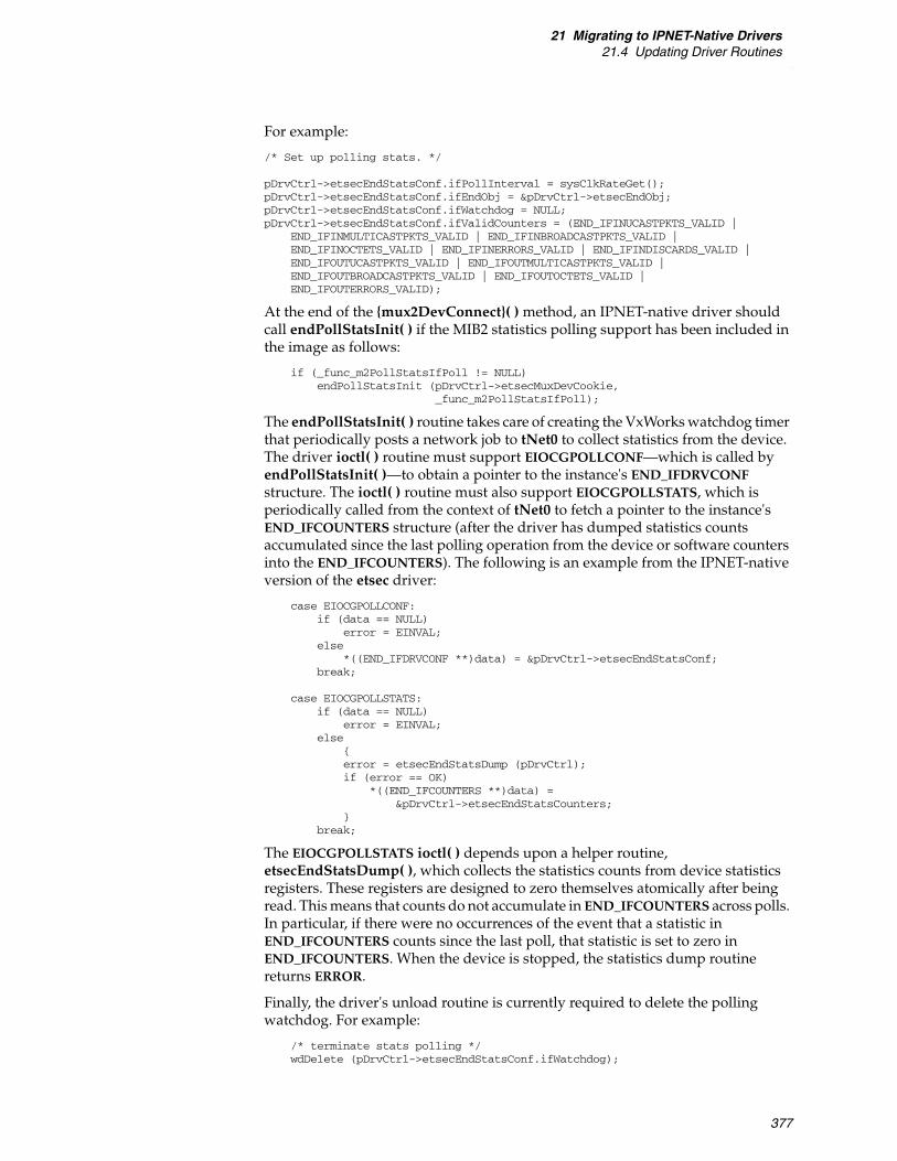
21 Migrating to IPNET-Native Drivers21.4 Updating Driver Routines
377
For example:
/* Set up polling stats. */
pDrvCtrl->etsecEndStatsConf.ifPollInterval = sysClkRateGet();pDrvCtrl->etsecEndStatsConf.ifEndObj = &pDrvCtrl->etsecEndObj;pDrvCtrl->etsecEndStatsConf.ifWatchdog = NULL;pDrvCtrl->etsecEndStatsConf.ifValidCounters = (END_IFINUCASTPKTS_VALID |
END_IFINMULTICASTPKTS_VALID | END_IFINBROADCASTPKTS_VALID |END_IFINOCTETS_VALID | END_IFINERRORS_VALID | END_IFINDISCARDS_VALID |END_IFOUTUCASTPKTS_VALID | END_IFOUTMULTICASTPKTS_VALID |END_IFOUTBROADCASTPKTS_VALID | END_IFOUTOCTETS_VALID |END_IFOUTERRORS_VALID);
At the end of the {mux2DevConnect}( ) method, an IPNET-native driver should call endPollStatsInit( ) if the MIB2 statistics polling support has been included in the image as follows:
if (_func_m2PollStatsIfPoll != NULL)endPollStatsInit (pDrvCtrl->etsecMuxDevCookie,
_func_m2PollStatsIfPoll);
The endPollStatsInit( ) routine takes care of creating the VxWorks watchdog timer that periodically posts a network job to tNet0 to collect statistics from the device. The driver ioctl( ) routine must support EIOCGPOLLCONF—which is called by endPollStatsInit( )—to obtain a pointer to the instance's END_IFDRVCONF structure. The ioctl( ) routine must also support EIOCGPOLLSTATS, which is periodically called from the context of tNet0 to fetch a pointer to the instance's END_IFCOUNTERS structure (after the driver has dumped statistics counts accumulated since the last polling operation from the device or software counters into the END_IFCOUNTERS). The following is an example from the IPNET-native version of the etsec driver:
case EIOCGPOLLCONF:if (data == NULL)
error = EINVAL;else
*((END_IFDRVCONF **)data) = &pDrvCtrl->etsecEndStatsConf;break;
case EIOCGPOLLSTATS:if (data == NULL)
error = EINVAL;else
{error = etsecEndStatsDump (pDrvCtrl);if (error == OK)
*((END_IFCOUNTERS **)data) =&pDrvCtrl->etsecEndStatsCounters;
}break;
The EIOCGPOLLSTATS ioctl( ) depends upon a helper routine, etsecEndStatsDump( ), which collects the statistics counts from device statistics registers. These registers are designed to zero themselves atomically after being read. This means that counts do not accumulate in END_IFCOUNTERS across polls. In particular, if there were no occurrences of the event that a statistic in END_IFCOUNTERS counts since the last poll, that statistic is set to zero in END_IFCOUNTERS. When the device is stopped, the statistics dump routine returns ERROR.
Finally, the driver's unload routine is currently required to delete the polling watchdog. For example:
/* terminate stats polling */wdDelete (pDrvCtrl->etsecEndStatsConf.ifWatchdog);

VxBusDevice Driver Developer's Guide, 6.9
378
If the device does not support collecting the required statistics in hardware, the driver must maintain statistics in software on a per-packet basis. The driver should contribute to at least some statistics. For example, the driver should count the software packets that it discards at input when its receive handler routine cannot allocate a replacement packet buffer.
As software counts are not auto-clearing like most device statistics registers, the driver must take care not to let counts accumulate across polls in the END_IFCOUNTERS structure. Wind River recommends that the driver maintain a set of free-running software counters that are incremented in the send and receive paths, and a second set of counters that are snapshots of the free-running counters updated during each poll.
To handle the EIOCGPOLLSTATS ioctl( ) routine in this model, the driver reads the current free-running count and remembers it for each supported statistic. The driver then subtracts the snapshot value of the count stored at the last poll to get the value to store in END_IFCOUNTERS. It stores the remembered current count in the snapshot counter. The snapshot counters are protected by the instance mutual exclusion taken in the driver ioctl( ) routine. For the free-running counters, the transmit counts are protected by being updated only with the transmit semaphore held, while the receive counts are protected by being updated only in the network task tNet0. You can assume that the free-running counters can be read and written atomically, so that there are no issues with the EIOCGPOLLSTATS code simply reading the free-running counters. This atomicity can restrict those counters (and their snapshots) to 32 bits. The polling interval is typically sufficiently short enough that there is no danger of wrapping a 32-bit counter during a single polling interval, even for the octet counts.
Maintaining software counts properly for the statistics generally requires examining the destination address in the link header to determine if it is unicast, multicast, or broadcast. (For received packets, sometimes the device may give an indication of this.)
For example:
endCounter ifInUcastPkts; endCounter ifInMulticastPkts; endCounter ifInBroadcastPkts;
endCounter ifOutUcastPkts; endCounter ifOutMulticastPkts; endCounter ifOutBroadcastPkts;
The following is possible output side code that is used to determine (in the Ethernet case) which count to update when statistics are being maintained in software by the driver:
#ifdef MYDEV_KEEP_SW_STATISTICSIp_u8 ch1;...ch1 = pkt->data[pkt->start];if (ch1 & 1)
{/* * For performance reasons, cheat a bit and assume broadcast* if the first byte of the destination address is 0xff*/if (ch1 == 0xff)
pDrvCtrl->freeStats.ifOutBroadcastPkts++;else
pDrvCtrl->freeStats.ifOutMulticastPkts++;}

21 Migrating to IPNET-Native Drivers21.5 Building, Integrating, and Testing Your Driver
379
elsepDrvCtrl->freeStats.ifOutUcastPkts++;
#endif /* MYDEV_KEEP_SW_STATISTICS */
Note that for the receive case, reading the received packet's data should be done only after the packet data cache has been made coherent—if necessary—by a vxbDmaBufSync( ) call using VXB_DMABUFSYNC_PREREAD (or similar method).
21.5 Building, Integrating, and Testing Your Driver
The final phase of IPNET-native driver migration involves building the driver, integrating it into your BSP and VxWorks, testing the driver, and performing any necessary cleanup.
Step 23: Build the Driver and Fix Build Issues
The driver should build cleanly on supported architectures for both Wind River supplied compilers. You must fix up any remaining issues (for example, variables you forgot to rename, retype, or remove) until the driver builds cleanly.
Note that if you are building for a VSB, you can avoid the full VSB rebuild. For example, the following is used for a PPC32 uniprocessor build using the Wind River Compiler:
> cd target/src/hwif/end2 > make CPU=PPC32 TOOL=diab VSB_DIR=pathToMyVsb
You can also build with the Wind River GNU Compiler as well. For example:
> make CPU=PPC32 TOOL=gnu VSB_DIR=pathToMyVsb clean > make CPU=PPC32 TOOL=gnu VSB_DIR=pathToMyVsb
Step 24: Add Auxiliary Driver Files
Besides the primary driver source file and header files for a VxBus network driver, there are some small auxiliary files used in the process of building VxWorks images.
Driver Configuration Stub Files
The following directory contains—for each VxBus driver—short code stubs that are used to generate the vxbUsrCmdLine.c file:
installDir/vxworks-6.x/target/config/comps/src/hwif
The vxbUsrCmdLine.c file is in turn used in the traditional BSP command-line build. For a typical network driver, only two files are needed in this directory: the driver.dc file that (conditionally) declares the driver's registration function and the driver.dr file that actually calls the driver registration function.
For example, here is the contents of the vxbGei825xxEnd2.dc file provided by the IPNET-native version of the gei driver:
#if defined (INCLUDE_GEI825XX_VXB_END) && defined (INCLUDE_GEI825XX_VXB_END2)#error "INCLUDE_GEI825XX_VXB_END and INCLUDE_GEI825XX_VXB_END2 are both
defined"#endif

VxBusDevice Driver Developer's Guide, 6.9
380
#if defined (INCLUDE_GEI825XX_VXB_END2) && !defined (INCLUDE_END2) #error "INCLUDE_GEI825XX_VXB_END2 requires INCLUDE_END2"#endif
IMPORT void geiEnd2Register(void);
The most important line is the declaration of the registration function. The other lines prevent a build from succeeding if both the traditional M_BLK-style (END) and the IPNET-native (END2) version of the gei driver are included in the image, or if the necessary general IPNET-native driver support is not configured in the image.
The vxbGei825xxEnd2.dr file is even simpler; it just calls the registration function (conditionally, if INCLUDE_GEI825XX_VXB_END2 is defined):
#ifdef INCLUDE_GEI825XX_VXB_END2geiEnd2Register();
#endif /* INCLUDE_GEI825XX_VXB_END2 */
These files are referred to as driver configuration stub files. For more information on these files, see 3. Device Driver Fundamentals.
Driver Component Description Files (CDFs)
Contrary to the code stubs in installDir/vxworks-6.x/target/config/comps/src/hwif, the driver .cdf file is used in VIP builds and not traditional BSP builds (make in the BSP directory). When an IPNET-native driver is based on an existing network driver, you need to add not just a new component for the IPNET-native version of the driver, but an option to select between the old and new versions of the driver.
Wind River sometimes adds the new IPNET-native driver component and the new versus old selection option to the existing M_BLK-style driver .cdf file. If you provide both a traditional M_BLK-style (END) and IPNET-native (END2) version of the driver, you can also choose to include these options.
The following shows the contents of the combined .cdf file for both versions of the Wind River provided etsec drivers:
/* 40vxbEtsecEnd.cdf - Component configuration file */
/* Copyright (c) 2007-2008 Wind River Systems, Inc. */
/*modification history--------------------01e,26sep08,dlk Remove unneded 'EXCLUDES' clauses for components in
a selection.01d,22jul08,dlk Eliminate duplicate INCLUDE_ETSEC_VXB_END2 component.
Also removed dependence upon particular PHY drivers.01c,29apr08,dlk Added INCLUDE_ETSEC_VXB_END2, SELECT_ETSEC_VXB_END.01b,22may08,dtr Remove requires for INCLUDE_BCM54XXPHY INCLUDE_MV88E1X11PHY.01a,20jun07,wap written*/
NOTE: If you choose to write an IPNET-native version of a traditional M_BLK-style driver provided by Wind River (that is, a network driver that Wind River has not yet converted to IPNET-native), Wind River suggests that you add a separate .cdf file for your IPNET-native version in order to avoid problems if the existing .cdf is updated by a Wind River patch.
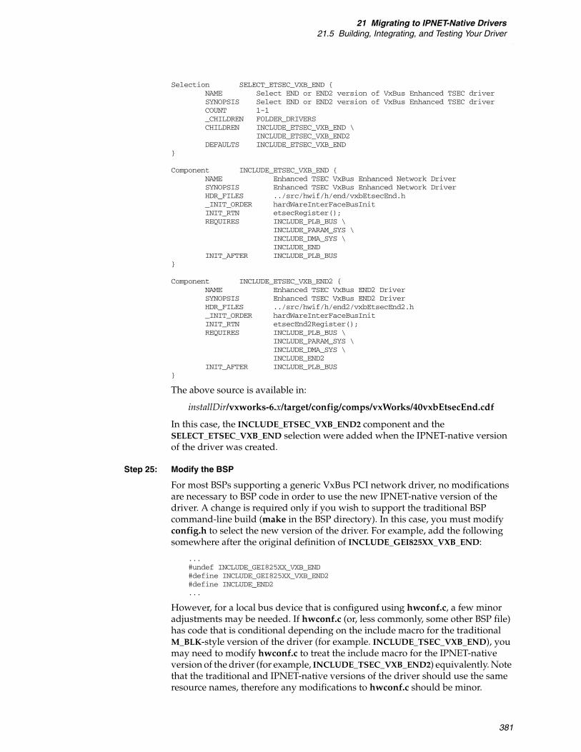
21 Migrating to IPNET-Native Drivers21.5 Building, Integrating, and Testing Your Driver
381
Selection SELECT_ETSEC_VXB_END {NAME Select END or END2 version of VxBus Enhanced TSEC driverSYNOPSIS Select END or END2 version of VxBus Enhanced TSEC driverCOUNT 1-1_CHILDREN FOLDER_DRIVERSCHILDREN INCLUDE_ETSEC_VXB_END \
INCLUDE_ETSEC_VXB_END2DEFAULTS INCLUDE_ETSEC_VXB_END
}
Component INCLUDE_ETSEC_VXB_END {NAME Enhanced TSEC VxBus Enhanced Network DriverSYNOPSIS Enhanced TSEC VxBus Enhanced Network DriverHDR_FILES ../src/hwif/h/end/vxbEtsecEnd.h_INIT_ORDER hardWareInterFaceBusInitINIT_RTN etsecRegister();REQUIRES INCLUDE_PLB_BUS \
INCLUDE_PARAM_SYS \INCLUDE_DMA_SYS \INCLUDE_END
INIT_AFTER INCLUDE_PLB_BUS}
Component INCLUDE_ETSEC_VXB_END2 {NAME Enhanced TSEC VxBus END2 DriverSYNOPSIS Enhanced TSEC VxBus END2 DriverHDR_FILES ../src/hwif/h/end2/vxbEtsecEnd2.h_INIT_ORDER hardWareInterFaceBusInitINIT_RTN etsecEnd2Register();REQUIRES INCLUDE_PLB_BUS \
INCLUDE_PARAM_SYS \INCLUDE_DMA_SYS \INCLUDE_END2
INIT_AFTER INCLUDE_PLB_BUS}
The above source is available in:
installDir/vxworks-6.x/target/config/comps/vxWorks/40vxbEtsecEnd.cdf
In this case, the INCLUDE_ETSEC_VXB_END2 component and the SELECT_ETSEC_VXB_END selection were added when the IPNET-native version of the driver was created.
Step 25: Modify the BSP
For most BSPs supporting a generic VxBus PCI network driver, no modifications are necessary to BSP code in order to use the new IPNET-native version of the driver. A change is required only if you wish to support the traditional BSP command-line build (make in the BSP directory). In this case, you must modify config.h to select the new version of the driver. For example, add the following somewhere after the original definition of INCLUDE_GEI825XX_VXB_END:
...#undef INCLUDE_GEI825XX_VXB_END#define INCLUDE_GEI825XX_VXB_END2#define INCLUDE_END2...
However, for a local bus device that is configured using hwconf.c, a few minor adjustments may be needed. If hwconf.c (or, less commonly, some other BSP file) has code that is conditional depending on the include macro for the traditional M_BLK-style version of the driver (for example. INCLUDE_TSEC_VXB_END), you may need to modify hwconf.c to treat the include macro for the IPNET-native version of the driver (for example, INCLUDE_TSEC_VXB_END2) equivalently. Note that the traditional and IPNET-native versions of the driver should use the same resource names, therefore any modifications to hwconf.c should be minor.

VxBusDevice Driver Developer's Guide, 6.9
382
Step 26: Build a VxWorks Image that Uses the New Driver
Verify that you can build a VxWorks image that contains the new driver as a VIP, and with a traditional BSP command-line build (make in the BSP directory). If any BSP supporting the driver also supports SMP images, build an SMP VIP as well.
Step 27: Test the Driver
When testing an IPNET-native driver that has been written based on an existing VxBus network driver, you should test the driver as if it is an entirely new driver. Although some functionality—such as PHY-level operation and multicast support—is generally unchanged between the M_BLK-style and IPNET-native versions, the basic transmit and receive paths—as well as the polled mode transmit and receive—are changed more extensively during the migration process. In general, if you are confident of the proper behavior of the original VxBus driver, you can proceed with testing as described in the remainder of this section.
After checking that basic functionality is working in the IPNET-native driver, concentrate on the basic network sanity tests such as:
■ Download symbol table.
■ Ping to and from target.
■ Telnet to target and execute commands that produce a lot of output.
■ Ping flood to the target.
■ Ping the target with large packets.
■ Use ping6 to test IPv6 connectivity. Note that this gives a basic test of multicast operation (through NDP operation).
Forwarding tests are probably the best tests for stressing the driver in terms of the packet-handling rate for both receive and transmit. TCP or UDP tests, with various packet sizes that test both streaming and request/response type traffic and test both transmit and receive, are necessary to test checksum offload operation and basic operation. For these tests, compare performance between the M_BLK-style and IPNET-native version of the same driver.
Test polled mode operation of your driver. For information on how to do this, see 11. Network Drivers.
Stop and start a device instance by calling muxDevStop( ) for your device, followed by muxDevStart( ) a bit later. Using the slab command at the command interpreter shell, you can see evidence of allocations by IPNET-native drivers from the packet pool. When an IPNET-native device is stopped using muxDevStop( ), the driver should return the packets it has allocated for the device's receive ring to the packet pool. This should be visible in the output of the slab command.
Wind River recommends that you test unregistering and reregistering your driver. For information on issues and restrictions for registering and unregistering your driver, see the troubleshooting information in 11. Network Drivers.

383
PAR T IV
Appendices
A Glossary .................................................................................... 385
B Checklist for Device Drivers .................................................... 389
C IPNET-Native Migration Checklist ........................................... 391

VxBusDevice Driver Developer's Guide, 6.9
384

385
AGlossary
access routine
A routine provided by VxBus that a driver calls in order to access or manipulate a device register.
advertise
Make available to VxBus, as with a driver method.
BAR
Base address register.
bus
A hardware mechanism for communication between the processor and a device, or between different devices. This term can also apply to processor-to-processor communication, such as with RapidIO or the processor local bus (PLB) on SMP and AMP systems.
bus controller
The hardware device that controls signals on a bus. The bus controller hardware must be associated with a bus controller device driver in order for VxBus to make use of the device. The service that a bus controller device driver provides is to support the devices downstream from the controller. The bus controller driver is also responsible for enumerating devices present on the bus. See also device, driver, enumeration, and instance.
bus discovery
See enumeration.
bus match
A VxBus procedure to create an instance whenever a new device or driver is made available. This procedure is used to determine if a given driver and device should be paired to form an instance.
bus type
A kind of bus, such as PCI or RapidIO. See also bus controller.

VxBusDevice Driver Developer's Guide, 6.9
386
child
A device that is attached to a bus.
cluster
Buffers used by netBufLib to hold packet data. See also mBlk.
descriptor
For direct memory access (DMA), a descriptor is a data structure shared by the device and driver, which communicates the size, location, and other characteristics of data buffers used to hold transmit and receive data. The data format is defined by the design of the device.
device
A hardware module that performs some specific action, usually visible (in some way) outside the processor or to the external system. See also bus, driver, and instance.
downstream
From the perspective of a device, downstream refers to a point farther from the CPU on the bus hierarchy. See also child.
driver
A compiled software module along with the infrastructure required to make the driver visible to Workbench and BSPs. The software module usually includes a text segment containing the executable driver code plus a small, static data segment containing information that is required to recognize whether the driver can manage a particular device. The infrastructure typically includes a CDF that allows integration with Workbench and vxprj, and stub files for integration with a BSP.
driver method
A driver method is a published entry point into a driver made available to an API in VxBus. Examples of methods include functionality such as connecting network interfaces to the MUX and discovery of interrupt routing. See also method ID.
enumeration
Enumeration refers to the discovery of devices present on a bus. For some bus types such as PCI, the bus contains information about devices that are present. For those bus types, dynamic discovery is performed during the enumeration phase. For bus types such as VME, which do not have such functionality, tables that describe the devices that may be present on the system are maintained in the BSP.
instance
A driver and device that are associated with each other. This is the minimal unit that is accessible to higher levels of the operating system. See also bus, device, and driver.
mBlk
Structure used to organize data buffers. See also cluster.

A Glossary
387
method ID
A method ID is the identification of a specific driver method that may be provided by a driver. This must be unique for each method (that is, specific functionality module) on the system. See also driver method.
parameter
Information about some aspect of device software configuration. For further discussion, see 3.6.1 Configuration, p.43. See also resource.
parent
The bus to which a device is attached, or the bus controller of that bus.
probe
See enumeration and probe routine.
probe routine
An entry point into drivers. After the system has tentatively identified a device as being associated with a driver, VxBus gives the driver a chance to verify that the driver is suitable to control the device. The driver registers the probe routine to perform this comparison. This routine is optional. If specified, it is normally safe and acceptable for the routine to simply indicate acceptance.
processor local bus (PLB)
The bus connected directly to a processor. This term is used in a processor-agnostic way in this documentation.
resource
information about some aspect of device hardware configuration. For further discussion, see 3.6.1 Configuration, p.43. See also parameter.
serial bitbang
Serial bitbang describes a scenario where software writes the individual bits of a word out on a serial line, often with a corresponding clock, rather than writing the entire value into a register and allowing the underlying hardware to take care of the delivery of the word.
service driver
A device driver that provides a service to the operating system or to middleware, instead of a service for another device driver. Examples of service drivers include drivers for serial and network devices.
stall
A condition that occurs when a network interface device stops operating due to momentary lack of resources.
upstream
From the perspective of a device, upstream refers to a point closer to the CPU on the bus hierarchy. See also parent.

VxBusDevice Driver Developer's Guide, 6.9
388

389
BChecklist for Device Drivers
This appendix includes a checklist to help you determine when your driver is ready for deployment or distribution. Successful completion of this checklist can help you assess the quality of your driver and make decisions with respect to deployment and distribution.
The checklist assumes you are familiar with VxBus device driver development or you have reviewed the information in the VxWorks device driver documentation set. (The items included in the checklist are discussed in detail throughout this documentation set.)
Table B-1 VxWorks Device Driver Release Checklist
Description Date
YYYY-MM-DDStatus
OK | FAIL | N/A
1. Install a clean product installation, including relevant patches.
2. Install the driver into the new installation.
3. Verify the README, makefile, .cdf, .dr, and .dc files are present in the driver specific directory.
4. Start Workbench and create a VxWorks image project (VIP) using a BSP that is relevant to the driver.
5. Open the project configuration window and verify that the driver shows up in the drivers folder.
6. If the device is located on a bus that allows device probe, such as PCI, plug in the device. If the device is located on a bus that does not allow device probe, such as PLB, modify the hwconf.c file to add an entry for the device and create a new VIP using the modified hwconf.c file. Boot the image without the driver.
7. Configure the VIP to include the driver. Verify that the image boots.
8. Configure the VIP to include show routines and VxBus show routines.
9. Boot the image and run vxBusShow( ). Verify that the driver is registered and the device is present as a device and not an orphan. Specifying the VxBus device ID of the device, call vxbDevStructShow( ), and verify that the driver field is non-null, and matches the driver.

VxBusDevice Driver Developer's Guide, 6.9
390
10. Repeat steps 4 through 7 for a boot ROM image. With the device present and the driver configured into the image, verify that the boot ROM loads and boots a VxWorks image.
11. Generate a list of all files installed by the driver product.
12. Verify that all files in the release are contained in the directory:
installDir/vxworks-6.x/target/3rdparty/vendor
13. Use the nmarch command to verify that there is only one global symbol present. The symbol should be the registration routine for the driver.
14. Verify that the VxBus version in the driver's registration structure matches the current VxBus version.
15. If the VxTest test suite is available, verify that all VxTest tests applicable to the driver class of this driver are successful.
Table B-1 VxWorks Device Driver Release Checklist (cont’d)
Description Date
YYYY-MM-DDStatus
OK | FAIL | N/A

391
CIPNET-Native Migration Checklist
This appendix includes a checklist to help you migrate a traditional M_BLK-oriented VxBus network driver to an IPNET-native VxBus network driver. The checklist includes the overall steps in this process as well as the subtasks for each step. Note that this appendix is not intended to provide detailed information on how to perform each of these steps. The overall steps include a cross-reference to the corresponding detailed section in 21. Migrating to IPNET-Native Drivers.
The checklist assumes you are familiar with VxBus device driver development and that you have reviewed 21. Migrating to IPNET-Native Drivers as well as the IPNET-native driver information in 11. Network Drivers.
NOTE: This release of VxWorks includes IPNET-native versions of the etsec, gei, and tsec network drivers. If you have a custom version of one of these drivers, you can use the steps in this appendix and in 21. Migrating to IPNET-Native Drivers to migrate your driver. These resources are also useful for migrating other network drivers (custom or Wind River-supplied).
Table C-1 VxWorks Device Driver IPNET-Native Migration Checklist
DescriptionDate
YYYY-MM-DD
Step 1:Copy, Relocate, and Rename the Existing Driver Source Files, p.359
Moved and renamed driver source files.
Updated all references to old file names.
Step 2:Add a Makefile Fragment (.mk) for the Driver, p.360
Created Makefile for new driver.
Step 3:Rename the Driver Registration Routine, p.360
Renamed registration routine in driver .c file.
Renamed registration routine prototype in driver .h file.
Fixed all comments and documentation that referred to the registration routine name.
Step 4:Change {muxDevConnect}( ) to {mux2DevConnect}( ), p.360
Changed muxDevConnect to mux2DevConnect in method table.
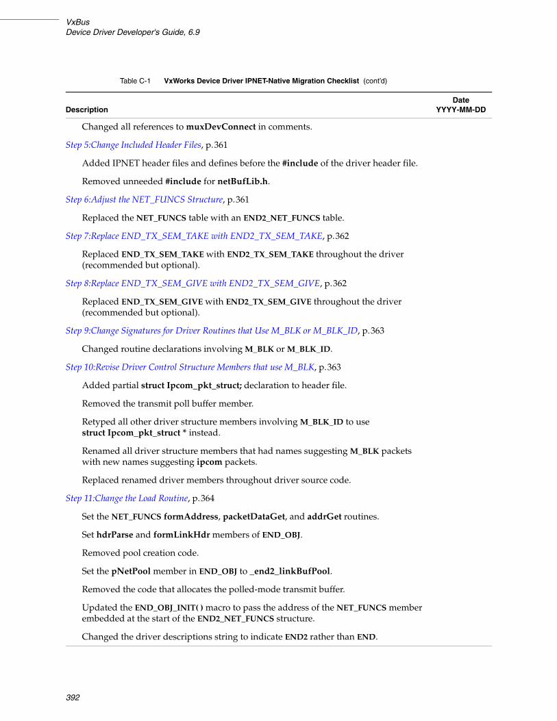
VxBusDevice Driver Developer's Guide, 6.9
392
Changed all references to muxDevConnect in comments.
Step 5:Change Included Header Files, p.361
Added IPNET header files and defines before the #include of the driver header file.
Removed unneeded #include for netBufLib.h.
Step 6:Adjust the NET_FUNCS Structure, p.361
Replaced the NET_FUNCS table with an END2_NET_FUNCS table.
Step 7:Replace END_TX_SEM_TAKE with END2_TX_SEM_TAKE, p.362
Replaced END_TX_SEM_TAKE with END2_TX_SEM_TAKE throughout the driver (recommended but optional).
Step 8:Replace END_TX_SEM_GIVE with END2_TX_SEM_GIVE, p.362
Replaced END_TX_SEM_GIVE with END2_TX_SEM_GIVE throughout the driver (recommended but optional).
Step 9:Change Signatures for Driver Routines that Use M_BLK or M_BLK_ID, p.363
Changed routine declarations involving M_BLK or M_BLK_ID.
Step 10:Revise Driver Control Structure Members that use M_BLK, p.363
Added partial struct Ipcom_pkt_struct; declaration to header file.
Removed the transmit poll buffer member.
Retyped all other driver structure members involving M_BLK_ID to use struct Ipcom_pkt_struct * instead.
Renamed all driver structure members that had names suggesting M_BLK packets with new names suggesting ipcom packets.
Replaced renamed driver members throughout driver source code.
Step 11:Change the Load Routine, p.364
Set the NET_FUNCS formAddress, packetDataGet, and addrGet routines.
Set hdrParse and formLinkHdr members of END_OBJ.
Removed pool creation code.
Set the pNetPool member in END_OBJ to _end2_linkBufPool.
Removed the code that allocates the polled-mode transmit buffer.
Updated the END_OBJ_INIT( ) macro to pass the address of the NET_FUNCS member embedded at the start of the END2_NET_FUNCS structure.
Changed the driver descriptions string to indicate END2 rather than END.
Table C-1 VxWorks Device Driver IPNET-Native Migration Checklist (cont’d)
DescriptionDate
YYYY-MM-DD

C IPNET-Native Migration Checklist
393
Step 12:Change the Unload Routine, p.366
Removed the code that frees the transmit polled-mode buffer.
Removed the code that calls endPoolDestroy( ) to destroy the driver’s M_BLK tuple pool.
Step 13:Change the Start Routine, p.366
Added code to allocate and initialize pEnd->pollPkt.
Modified initialization of the receive ring to use Ipcom_pkt packets rather than M_BLK packets.
Step 14:Change the Stop Routine, p.367
Modified code that drains the IX ring to use Ipcom_pkt rather than M_BLK.
Modified code that frees all packets from the receive ring to use Ipcom_pkt rather than M_BLK.
Added code that frees the polling buffer pEnd->pollPkt and clears pEnd->pollPkt.
Step 15:Change the Send Routine, p.368
Modified the send routine to use Ipcom_pkt packets instead of M_BLK packets.
Handled the coalescing-required case.
Step 16:Change the Transmit Encapsulation Routine, p.370
Converted the transmit encapsulation routine to use Ipcom_pkt packets and the Ipcom_pkt checksum offload and VLAN tag insertion offload interface.
Step 17:Change the Transmit Cleanup Code, p.370
Converted the transmit cleanup code to use Ipcom_pkt packets.
Step 18:Change the Receive Handler Routine, p.371
Renamed the M_BLK_ID variables.
Allocated replacement packet using vxipcom_pkt_malloc( ).
Initialized newpkt->start correctly.
If using vxbDmaBufIpcomLoad( ), set pkt->end to pkt->maxlen.
Modified the code to swap the received packet and the replacement packet.
Modified the code to record the received frame’s length.
Modified the code to set the replacement packet’s buffer address in the reused receive DMA descriptor, or else modified the code to use vxbDmaBufMapIpcomLoad( ) in place of vxbDmaBufMapMblkLoad( ).
Changed the receive per-packet checksum offload and VLAN tag extraction offload code to use the Ipcom_pkt interface.
Table C-1 VxWorks Device Driver IPNET-Native Migration Checklist (cont’d)
DescriptionDate
YYYY-MM-DD

VxBusDevice Driver Developer's Guide, 6.9
394
Changed the code to call END2_RCV_RTN_CALL( ) in place of END_RCV_RTN_CALL( ).
Step 19:Change the ioctl( ) Routine, p.373
Added support for the EIOCGSTYLE ioctl( ) routine.
Modified EIOCPOLLSTART to drain the transmit ring using Ipcom_pkt instead of M_BLK.
Step 20:Change the Polled-Mode Send Routine, p.373
Modified the polled send routine to expect and use an Ipcom_pkt pointer instead of an M_BLK_ID.
Step 21:Change the Polled-Mode Receive Routine, p.374
Modified the polled receive routine to expect and use an Ipcom_pkt pointer instead of M_BLK_ID.
Step 22:Change Statistics Collection, p.375
If not already used, switched to polled-mode statistics interface.
Step 23:Build the Driver and Fix Build Issues, p.379
Built the driver successfully without warnings using both the Wind River Compiler (diab) and the Wind River GNU Compiler (gnu).
Step 24:Add Auxiliary Driver Files, p.379
Created the driver configuration stub files (driver.dc and driver.dr) in installDir/vxworks-6.x/target/config/comps/src/hwif.
Created the driver component description file (CDF) or modified the existing .cdf file.
Step 25:Modify the BSP, p.381
Modified the related BSP code (config.h and hwconf.c) if required.
Modified hwconf.c as required to treat M_BLK-oriented and IPNET-native driver versions equivalently.
Step 26:Build a VxWorks Image that Uses the New Driver, p.382
Successfully built a VxWorks image with the new driver using a traditional BSP build.
Successfully built a VxWorks image with the new driver using Workbench.
Step 27:Test the Driver, p.382
Performed basic sanity tests.
Executed performance tests for IP forwarding with Ethernet fast path enabled.
Executed TCP and UDP performance tests over IPv4 and IPv6.
If desired, tested multi-segment transmit support using TIPC or sending using the ZBUF socket interface.
Table C-1 VxWorks Device Driver IPNET-Native Migration Checklist (cont’d)
DescriptionDate
YYYY-MM-DD

C IPNET-Native Migration Checklist
395
Executed the WTX test in order to test polled mode.
Tested the driver stop and restart functionality.
Tested the driver unregister, register, and reconnect to MUX functionality.
Table C-1 VxWorks Device Driver IPNET-Native Migration Checklist (cont’d)
DescriptionDate
YYYY-MM-DD

VxBusDevice Driver Developer's Guide, 6.9
396

397
Index
Symbols(*busCfgRead)( )
overriding 114(*busCfgWrite)( )
overriding 114(*dmaCancel)( ) 136(*dmaPause)( ) 136(*dmaRead)( ) 135(*dmaReadAndWait)( ) 135(*dmaStatus)( ) 136(*dmaWrite)( ) 135(*dmaWriteAndWait)( ) 135(*timerAllocate)( ) 311(*timerCountGet)( ) 312(*timerCountGet64)( ) 316(*timerDisable)( ) 313(*timerEnable)( ) 314(*timerEnable64)( ) 315(*timerISRSet)( ) 314(*timerRelease)( ) 311(*timerRolloverGet)( ) 312(*timerRolloverGet64)( ) 315(*vxbDevControl)( )
overriding 114(*xf_dump)( ) 297, 300(*xf_ioctl)( ) 297, 299, 301(*xf_strategy)( ) 297, 300_CHILDREN 343_INIT_ORDER 342{busCtlrAccessOverride}( ) 113{busCtlrBaseAddrCvt}( ) 115{busCtlrCfgInfo}( ) 115{busCtlrCfgRead}( ) 110{busCtlrCfgWrite}( ) 111{busCtlrDevCfgRead}( ) 109{busCtlrDevCfgWrite}( ) 111{busCtlrDevCtlr}( ) 112{busDevShow}( ) 94, 153{cpmCommand}( ) 282{driverControl}( ) 282, 332{instParamModify}( ) 46{isrRerouteNotify}( ) 71, 164
{m85xxLawBarAlloc}( ) 282{miiBusRead}( ) 236{miiLinkUpdate}( ) 237, 241{miiMediaUpdate}( ) 180, 183, 195, 368{miiModeGet}( ) 195, 239{miiModeSet}( ) 195, 238{miiRead}( ) 180, 184, 194, 195, 237, 241{miiWrite}( ) 180, 185, 194, 237, 241{mux2DevConnect}( ) 180, 196, 197, 229, 231, 360, 377{muxConnect}( ) 242{muxDevConnect}( ) 180, 196, 197, 229, 231{muxDevConnect2}( ) 181{nonVolGet}( ) 244{nonVolSet}( ) 245{sioChanConnect}( ) 287{sioChanGet}( ) 286{vxbDevRegMap}( ) 116{vxbDmaResDedicatedGet}( ) 62, 133{vxbDmaResourceGet}( ) 132{vxbDmaResourceRelease}( ) 63, 133{vxbDrvUnlink}( ) 39, 180, 183, 227, 231, 325
see also dissociating a device from a driver{vxbIntCtlrConnect}( ) 142{vxbIntCtlrCpuReroute}( ) 144, 163{vxbIntCtlrDisable}( ) 143{vxbIntCtlrDisconnect}( ) 142{vxbIntCtlrEnable}( ) 143{vxbIntCtlrIntReroute}( ) 144{vxbIntDynaVecConnect}( ) 143, 160{vxbIntDynaVecProgram}( ) 120, 161{vxbTimerFuncGet}( ) 306{vxIpiControlGet}( ) 145, 165
NumericspRegBase 8600tffs.cdf 25840driverName.cdf 9864-bit devices
physical-to-virtual address translation 72virtual-to-physical address mapping 71

VxBusDevice Driver Developer's Guide, 6.9
398
64-bit driversmemory mapping 71porting 73
802.1q VLAN tag extraction 213
Aaccess routine 385accessing hardware 49accessing MII management registers 184adding
debug code 81driver methods 81
adding a makefile fragment for IPNET-native drivers 360
addressconversion for bus controllers 60translation, considerations for DMA 59
address spacemapping 50
address translationDMA 193for USB drivers 326in bus controller drivers 115
addrGetIPNET-native drivers 361
advertise 385advertising driver methods 34advertising XBD methods 299allocating
device structures 171DMA channels 132external DMA engines 62memory 46, 48
during system operation 48during system startup 47
system resources 281timers 307, 311tuples from the pool 193
AMD/Fujitsu flash devicesCFI 251non-CFI 252
amdmtd.c 252analog-to-digital converters 331announcing
a downstream bus 125devices to VxBus 128, 171
array 71ATA 14ATA commands 302ATA_RESOURCE 296ATA_TYPE 296ataResources 296ataTypes 296atomic operators 64atomic_t 64autoIntRouteSet 123
auxiliary clock 319
BBAM 249, 269BAR 385base address register 385binding a network device to the stack 180, 181bio 297, 300bio.h 300bio_done( ) 297, 301block allocation map, see BAMboot block 251boot process 35
early phase 36bridgePostConfigFuncSet 123bridgePreConfigFuncSet 123BSP
configuration 44, 65device parameter configuration 67hwconf.c 96modifications for drivers 80
BSP configurationbus controller drivers 121CPU routing table 148DMA drivers 134dynamic vector table 148dynamic vectors 160interrupt controller drivers 146interrupt input table 146interrupt priority 149MAC drivers 186multifunction drivers 170NVRAM drivers 245other class drivers 333PHY drivers 239resource drivers 282resources for a PCI bus 121serial drivers 288storage drivers 296timer drivers 309USB drivers 326
BSP resourcesataResources 296ataTypes 296clkFreq 309clkRateMax 309clkRateMin 309cpuClkRate 309for PCI autoconfiguration 123inputTableSize 147miiIfName 186miiIfUnit 186numSegments 245phyAddr 186priority 149priorityTableSize 149

Index
399
segments 245BSPs
modifications for IPNET-native drivers 381buffer management 189
IPNET-native drivers 189M_BLK-style drivers 192
BUFFER_WRITE_BROKEN 250building and testing IPNET-native drivers 379bus
definition 385discovery 385match 385
bus controlleraddress conversion 60definition 385drivers 16
bus controller drivers 107address translation 115BSP configuration 121communication 108debugging 129deferring driver initialization 129driver methods 109generating configuration transactions 115header files 121initialization 126initialization example 127location in VxWorks 108overriding service routines 113overview 107utility routines 123
bus controllersconnecting to devices 125
bus type 385macros 125PCI 42PLB 42RapidIO 42registering with VxBus 128
Ccache
considerations for DMA 61CACHE_DRV_PHYS_TO_VIRT( ) 72CACHE_DRV_VIRT_TO_PHYS( 72cacheLib 61cacheSize 123callbackInstall( ) 290calling driver methods 33calling the socket registration routines 261cancelling an operation on a DMA channel 136cap_available 206cap_enabled 206, 214CDF 342
CFG_PARAMS 343IPNET-native drivers 380
keywords_CHILDREN 343_INIT_ORDER 342Component 342Parameter 343
CDF, see component description fileCDFs
00tffs.cdf 258CFG_PARAMS 27, 343CFI 249
AMD/Fujitsu command set 249AMD/Fujitsu flash devices 251Intel/Sharp command set 249
CFI/SCS flash support 250CFI_DEBUG 250cfiamd.c 249cfiscs.c 249, 250changes in device parameters 46checksum offload
IPNET-native drivers 375M_BLK-style drivers 214per-packet interface for IPNET-native drivers
209, 212child 386classes, see driver classesclkFreq 67, 309, 354clkRateMax 309clkRateMin 309CLOCAL 290cluster 202, 386command-line builds
using make 28commands
nmarch 345, 354slab 382
common flash interface, see CFIcommunication
between device, driver, and OS 9communication, bus controller 108comparing
device and driver names 96comparing IPNET-native and M_BLK-oriented
network drivers 358component 7, 23
DRV_DEMO_WRSAMPLE 99INCLUDE_ISR_DEFER 70INCLUDE_PCI_BUS_SHOW 93INCLUDE_SHOW_ROUTINES 81, 93INCLUDE_VXBUS_SHOW 81, 93parameters
ISR_DEFER_MODE 70Component CDF keyword 342component description file 23, 78, 98
example 24fields
CFG_PARAMS 27CHILDREN 26Component 24HDR_FILES 27

VxBusDevice Driver Developer's Guide, 6.9
400
INIT_AFTER 27INIT_BEFORE 27INIT_ORDER 26INIT_RTN 26MODULES 25NAME 25Parameter 27PROTOTYPE 26REQUIRES 26SYNOPSIS 25
parameter keywordsDEFAULT 28NAME 28SYNOPSIS 28TYPE 28
writing 24components
adding MTD components 258INCLUDE_ETSEC_VXB_END2 381INCLUDE_GENERICPHY 236, 239INCLUDE_GENERICTBIPHY 237, 239INCLUDE_MII_BUS 234, 239INCLUDE_NON_VOLATILE_RAM 245INCLUDE_PARAM_SYS 239
config.hMTD identification 260
configurationdriver services 43in hwconf.c 44information 44resource 44
configuration stub files 28, 79, 98, 343IPNET-native drivers 379
configuringBSP resources for PCI bus 121BSPs 44, 65device parameters in a BSP 67interrupt controllers 151interrupt show routines 93parameters 45show routines into VxWorks 93VxBus show routines 94
confirming register access 96connecting
an ISR to a timer 314bus controllers to devices 125ISRs 142networking code 196
console drivers 18copying data to and from NVRAM 244CPU routing table 148cpuClkRate 309CREAD 290creating
a new bus 172an MII bus instance 194an XBD 298buffer pools 193
creating the VxBus infrastructure 78
crossbar routing table 150CSIZE 290CSUM_DATA_VALID 208, 214CSUM_DELAY_DATA 208CSUM_DELAY_DATA6 208CSUM_DELAY_IP 208csum_flags_rx 206csum_flags_tx 206, 209, 210, 215CSUM_FRAGMENT 207CSUM_IP 206, 215CSUM_IP_CHECKED 207, 214CSUM_IP_FRAGS 207CSUM_IP_HDRLEN 216CSUM_IP_VALID 207, 214CSUM_IPHDR_LEN 208CSUM_IPHDR_OFFSET 208, 216CSUM_PSEUDO_HDR 208, 214CSUM_PTAGGED 207CSUM_RESULTS 208CSUM_TCP 206, 209, 215CSUM_TCP_SEG 207CSUM_TCPv6 207, 209, 215CSUM_TCPv6_SEG 207CSUM_UDP 206, 209, 215CSUM_UDPv6 207, 215CSUM_VLAN 207, 210CSUM_XPORT_CSUM_OFF 208, 216custom drivers 331
Ddata buffers
address mapping 60data structures
VXB_DEVICE 49VXB_DEVICE_ID 82
data structures, see structuresdata_freefunc_cookie 192DEBUG_PRINT 250debugging 81, 94, 95
bus controller drivers 129DMA drivers 137interrupt controller drivers 168MAC drivers 225multifunction drivers 174NVRAM drivers 247other class drivers 334PHY drivers 241register access 96resource drivers 283serial drivers 293storage drivers 303timer drivers 321USB drivers 328
deferral task 69

Index
401
deferringdriver registration 95driver registration for MAC drivers 225interrupt processing in an SMP system 69ISRs 197
defining MTDsas VxWorks components 258in the socket driver file 259
deleting an MII bus 194descriptor 386design goals 11destAddrOffset
IPNET-native drivers 362destSize
IPNET-native drivers 362developing new VxBus drivers 77development life cycle 35device
ATA 14bus controllerdefinition 386display 18DMA engines 16Ethernet 15floppy disks 14interrupt controller 17keyboard 18MAC 15matching to a driver 41, 80mouse 18multifunction 17network interface 15non-volatile RAM 15parameter configuration in BSP 67PHY 15PLB 65responding to changes in parameters 46SCSI 14serial 14serial ATA 14timer 16USB 17
device registersaddress mapping 60
devicesaccessing MII management registers 184AMD/Fujitsu flash, CFI 251AMD/Fujitsu flash, non-CFI 252CFIcreating an XBD 298enumeration 127flash 243, 249Intel 28F008 flash 251Intel 28F016 flash 251interactions on multifunction chips 172interleaved registers 172multiple devices on a single chip 169NAND 252network device initialization 196
PHY 194device probing and discovery 234
registering with VxBus 128shared resources 173timers 305
devInstanceConnect( ) 36, 38see also initialization – VxBus phases
devInstanceInit( ) 36, 37see also initialization – VxBus phases
devInstanceInit2( ) 36, 38, 41, 190, 191see also initialization – VxBus phases
DEVMETHOD( ) 34DEVMETHOD_CALL( ) 33DEVMETHOD_END 34devResourceGet( ) 44, 246digital-to-analog converters 331direct memory access drivers, see DMA driversdirect memory access, see DMAdisabling
interrupt inputs 142ISRs 143, 152timer interrupt generation 313
discoveringdevices 128PHY devices 234
discovering hardware 41disk-on-chip support 252dispatching
interrupts 154ISRs 157
dissociating a device from a driver 39see also {vxbDrvUnlink}( )
distributing drivers 97DMA 58
address translation 59allocating external DMA engines 62cache considerations 61DMA tag 58engines 177support 193support for IPNET-native drivers 193
DMA channelcancelling an operation on 136getting status of 136pausing a 136queueing a read operation 135queueing a write operation 135
DMA controller drivers 16DMA drivers 131
BSP configuration 134debugging 137driver methods 132header files 133initialization 134overview 131structures and routines 134utility routines 134
DMA_COPY_MODE_DEVBUF 63DMA_COPY_MODE_FIFO 63

VxBusDevice Driver Developer's Guide, 6.9
402
DMA_COPY_MODE_NO_HW 63DMA_COPY_MODE_NO_SOFT 62, 63DMA_IDLE 136DMA_NOT_USED 136DMA_PAUSED 136DMA_RUNNING 136DMA_TRANSFER_TYPE_RD 63DMA_TRANSFER_TYPE_WR 63documentation
about 106additional 5class-specific device drivers 4conventions 5intended audience 4legacy drivers 3migrating device drivers 3navigating 4
downstream 386driver
bus controller 16console 18definition 386DMA controller 16file location 20for Ethernet devices 15initialization 35interrupt controller 17legacy file location 20MAC 15makefile 31matching to a device 41, 80multifunction 17network interface 15non-volatile RAM 15organization 19PHY 15registration order 41remote processing element 18required files 21resource 19run-time life cycle 35run-time operation 39serial 14services available to 43source file 21, 78
example 21storage 14synchronization 55third-party 20timer 16USB 17wrsample 20, 99
driver class 14bus controller 16console 18DMA controller 16documentation for class-specific drivers 4interrupt controller 17multifunction 17
network interface 15non-volatile RAM 15other 19remote processing element 18resource 19serial 14storage 14timer 16USB 17
driver classes 105bus controller 107direct memory access 131interrupt controller 139multifunction 169network 175network interface (MAC) 177NVRAM 244other 331PHY 233resource 173, 281serial 285timer 305USB 323
driver methods 8, 32{busCtlrAccessOverride}( ) 113{busCtlrBaseAddrCvt}( ) 115{busCtlrCfgInfo}( ) 115{busCtlrCfgRead}( ) 110{busCtlrCfgWrite}( ) 111{busCtlrDevCfgRead}( ) 109{busCtlrDevCfgWrite}( ) 111{busCtlrDevCtlr}( ) 112{busDevShow}( ) 94, 153{cpmCommand}( ) 282{driverControl}( ) 282, 332{instParamModify}( ) 46{isrRerouteNotify}( ) 71, 164{m85xxLawBarAlloc}( ) 282{miiBusRead}( ) 236{miiLinkUpdate}( ) 237, 241{miiMediaUpdate}( ) 180, 183, 195, 368{miiModeGet}( ) 195, 239{miiModeSet}( ) 195, 238{miiRead}( ) 180, 184, 194, 195, 237, 241{miiWrite}( ) 180, 185, 194, 237, 241{mux2DevConnect}( ) 180, 196, 197, 229, 231, 360,
377{muxConnect}( ) 242{muxDevConnect}( ) 180, 196, 197, 229, 231{muxDevConnect2}( ) 181{nonVolGet}( ) 244{nonVolSet}( ) 245{sioChanConnect}( ) 287{sioChanGet}( ) 286{vxbDevRegMap}( ) 116{vxbDmaResDedicatedGet}( ) 62, 133{vxbDmaResourceGet}( ) 132{vxbDmaResourceRelease}( ) 63, 133{vxbDrvUnlink}( ) 39, 180, 183, 227, 231, 325

Index
403
{vxbIntCtlrConnect}( ) 142{vxbIntCtlrCpuReroute}( ) 144, 163{vxbIntCtlrDisable}( ) 143{vxbIntCtlrDisconnect}( ) 142{vxbIntCtlrEnable}( ) 143{vxbIntCtlrIntReroute}( ) 144{vxbIntDynaVecConnect}( ) 143, 160{vxbIntDynaVecProgram}( ) 120, 161{vxbTimerFuncGet}( ) 306{vxIpiControlGet}( ) 145, 165adding 81advertising 34bus controller drivers 109calling 33definition 386DMA drivers 132interrupt controller drivers 142invoking 38limitations 35MAC drivers 180multifunction drivers 170multiprocessor systems 144NVRAM drivers 244other class drivers 332parts of 32PHY drivers 237resource drivers 282routine prototype 33serial drivers 286storage drivers 296syntax 32timer drivers 306USB drivers 325
driver receive handler routine 371driver routines
load, IPNET-native 364polled-mode receive, IPNET-native 374polled-mode send, IPNET-native 373registration, IPNET-native 360send, IPNET-native 368start, IPNET-native 366stop, IPNET-native 367unload, IPNET-native 366
driverAccessFunc( ) 119driverName.dc 29, 79, 98driverName.dr 29, 79, 98DRV_CTRL 127DRV_DEMO_WRSAMPLE 99dstAddr
IPNET-native drivers 365dynamic vector assignment 143dynamic vector table 148dynamic vectors 141
configuringin the BSP 160using service driver routines 160
determining values for 161interrupt assignment 120programming 161
EEHCI 324EIOCGIFCAP 205, 209, 210, 215EIOCGIFMEDIA 195EIOCGIFMEDIALIST 195EIOCGNPT 196EIOCGPOLLCONF 375EIOCGPOLLSTATS 375EIOCGSTYLE 196, 373EIOCPOLLSTART 373EIOCPOLLSTOP 373EIOCSIFCAP 205, 206, 208enabling
interrupt inputs 143ISRs 152timer interrupt generation 314
encoding I/O operations 120END_CAPABILITIES 205, 208, 209, 210, 214, 215END_ERR_BLOCK 368END_IFCOUNTERS 375END_IFDRVCONF 375END_MEDIALIST 195END_MUXSEND_RTN 361END_OBJ 196
IPNET-native drivers 366END_POLLRCV_RTN 361END_RCV_RTN_CALL( ) 372END_STYLE_END 196END_STYLE_END2 196, 373END_TX_SEM_GIVE 362END_TX_SEM_TAKE 362END2 358END2 drivers
see also IPNET-native drivers 175END2_LINKBUFPOOL_CLSIZE 233END2_LINKBUFPOOL_NTUPLES 232END2_NET_FUNCS 361END2_RCV_RTN_CALL( ) 372END2_TX_SEM_TAKE 362end2BufferPoolConfig( ) 190, 191endCommon.h 205endEtherAddressForm( )
IPNET-native drivers 361endEtherHdr.c
IPNET-native drivers 361endEtherPacketAddrGet( )
IPNET-native drivers 361endEtherPacketDataGet( )
IPNET-native drivers 361endian conversion for USB data transfers 326endLib 193endLib.c 192endLoad( ) 196endM2Packet( ) 375endMedia.h 238, 239endPollStatsInit( ) 377endPoolCreate( ) 192

VxBusDevice Driver Developer's Guide, 6.9
404
endPoolDestroy( ) 192, 193IPNET-native drivers 366
endPoolJumboCreate( ) 193endPoolTupleFree( ) 192, 193endPoolTupleGet( ) 192, 193, 203Enhanced Host Controller Interface, see EHCIenhanced network drivers, see END driversENOSPC 368enumeration 386
device 127, 128erasableBlockSize 258erase units 276ERF 298
event reporting 301event types 301new device notification 300registering 298
ERF_ASYNC_PROC 300ERF_SYNC_PROC 300erfEventRaise( ) 297, 300, 301erfHandlerRegister( ) 297, 299erfHandlerUnregister( ) 297, 299errInt 67errIntLevel 67Ethernet 15, 176event reporting framework, see ERFexamples
VxBus show routine output 83VxBus show routine verbose output 85
extended block device, see XBDEXTRA_INCLUDE 145
FfbbEnable 123files
00tffs.cdf 25840driverName.cdf 98amdmtd.c 252cfiamd.c 249cfiscs.c 249, 250component description file 23, 78, 98config.h 260configuration stub files 28, 79driver source 78driverName.dc 29, 79, 98driverName.dr 29, 79, 98endCommon.h 205endLib.c 192hwconf.c 146, 239, 344I28F008.c 251i28f016.c 251in a device driver 19initialization 30ipnet_eth.h 214location 20
for third-party drivers 98
makefile 31, 98mbuf.h 206miiBus.c 194miiBus.o 234README 30, 98, 99required 21sysTffs.c 250, 251, 252, 258, 259, 260, 261tffsConfig.c 253, 260third-party drivers 20usbPciStub.c 326vendor makefile 31vxbAuxClkLib.c 319vxbIntCtlrLib.c 153vxbIntelIchStorage.c 302vxbMethodDecl.h 100vxbPci.c 124vxbSI31xxStorage.c 302vxbSysClkLib.c 317vxbTimestampLib.c 320vxBus.c 171vxbUsrCmdLine.c 30, 100, 379vxmux_config.h 198vxmux_pkt.h 198wrsample driver 20
finding interrupt inputs 152finding the address of hardware registers 49flash
device layout 276erase units 276interleaved chips 276
flash file system support, see TrueFFSflash translation layer, see FTLFLASH_BASE_ADRS 263FLASH_SIZE 263flbase.h 255flDelayMsec( ) 262flDontNeedVpp( ) 256FLFlash 253, 258flflash.h 253flNeedVpp( ) 256floppy disks 14flSetWindowSize( ) 263FLSocket 255, 262, 266flSocketOf( ) 264flsystem.h 258flWriteProtected( ) 256FOLDER_DRIVERS 343formAddress
IPNET-native drivers 361formLinkHdr( )
IPNET-native drivers 365freeing a DMA channel 133FTL 249, 266
overview 270structures 271terminology 267
function pointers(*busCfgRead)( ) 114(*busCfgWrite)( ) 114

Index
405
(*dmaCancel)( ) 136(*dmaPause)( ) 136(*dmaRead)( ) 135(*dmaReadAndWait)( ) 135(*dmaStatus)( ) 136(*dmaWrite)( ) 135(*dmaWriteAndWait)( ) 135(*timerAllocate)( ) 311(*timerCountGet)( ) 312(*timerCountGet64)( ) 316(*timerDisable)( ) 313(*timerEnable)( ) 314(*timerEnable64)( ) 315(*timerISRSet)( ) 314(*timerRelease)( ) 311(*timerRolloverGet)( ) 312(*timerRolloverGet64)( ) 315(*vxbDevControl)( ) 114(*xf_dump)( ) 297, 300(*xf_ioctl)( ) 297, 299, 301(*xf_strategy)( ) 297, 300vxbIntDynaCtlrInputInit( ) 154vxbIntDynaVecProgram( ) 155
Ggenerating
bus controller configuration transactions 115dynamic vectors 154
genericPhy 234, 236, 239genericTbiPhy 236genericTbiPhy.h 236getting
an ISR function pointer 152arguments for an ISR 152flags for an interrupt input 152status of a DMA channel 136
global symbols 23global variables
removing 82
Hhandling
corrupt packets with M_BLK-style drivers 214interrupts 198network interrupts 179
hardwareaccess 49discovery 36, 41memory pool size 96registers
finding the address of 49reading and writing 50special requirements 52
hardWareInterFaceBusInit 342hardWareInterFaceBusInit( ) 37, 38hardWareInterFaceInit( ) 37HCDs 324HCF_RES_ADDR 44, 121, 122, 147, 354HCF_RES_INT 44, 121, 122, 147HCF_RES_LONG 44HCF_RES_STRING 44hdrParse( )
IPNET-native drivers 365header files 78
bio.h 300bus controller drivers 121DMA drivers 133endMedia.h 238, 239flbase.h 255flflash.h 253flsystem.h 258genericTbiPhy.h 236hwConf.h 66interrupt controller drivers 145MAC drivers 185multifunction drivers 170NVRAM drivers 245other class drivers 333PHY drivers 239resource drivers 282serial drivers 287sioLib.h 286, 289sioLibCommon.h 290storage drivers 296, 309USB drivers 325usbHst.h 325usbOsal.h 325vxbAccess.h 113, 118vxbDmaDriverLib.h 132vxbDmaLib.h 134vxbIntCtlrLib.h 145vxbIntrCtlr.h 145vxbNonVol.h 245vxbTimerLib.h 307vxBus.h 33, 125, 170xbd.h 299
heartbeat interrupt 306hEND drivers, see hierarchical END driversHEND_RX_QUEUE_PARAM 189hierarchical END drivers 242host controller drivers, see HCDsHUPCL 290hwconf.c 44, 45, 65, 151, 239, 344
interrupt controller resources 146NVRAM 246supplying a register base address 96USB drivers 326
hwConf.h 66HWMEM_ALLOC_FAIL_DEBUG 47HWMEM_POOL 96hwMemAlloc( ) 47, 127, 310
see also memory allocation

VxBusDevice Driver Developer's Guide, 6.9
406
hwMemFree( ) 47see also memory allocation
II28F008.c 251i28f016.c 251identifying interrupts 140IFCAP_CAP0 206IFCAP_CAP1 206IFCAP_CAP2 206IFCAP_CAP3 206IFCAP_IPCOMP 206IFCAP_IPSEC 205IFCAP_JUMBO_MTU 205IFCAP_NETCONS 205IFCAP_RXCSUM 205, 212, 214IFCAP_RXSUM 208IFCAP_TCPSEG 205IFCAP_TXCSUM 205, 209IFCAP_VLAN_HWTAGGING 205, 210, 213IFCAP_VLAN_MTU 205ifconfig( ) 226, 227ifEndObj 376IFM_ACTIVE 239IFM_AUTO 195, 241IFM_AVALID 239ifPollInterval 376ifValidCounters 376ifWatchdog 376implementing
timer driver service routines 311VxWorks auxiliary clock 319VxWorks system clock 317VxWorks timestamp drivers 320
in_cksum_skip( ) 216INCLUDE_EHCI 328INCLUDE_END2 232INCLUDE_END2_LINKBUFPOOL 232INCLUDE_ETSEC_VXB_END2 381INCLUDE_GENERICPHY 236, 239INCLUDE_GENERICTBIPHY 237, 239INCLUDE_HWMEM_ALLOC 37
see also memory allocationINCLUDE_ISR_DEFER 70INCLUDE_MII_BUS 234, 239INCLUDE_MTD_AMD 252INCLUDE_MTD_CFISCS 250INCLUDE_MTD_I28F008 252INCLUDE_MTD_I28F016 251INCLUDE_NON_VOLATILE_RAM 245INCLUDE_OHCI 328INCLUDE_PARAM_SYS 239INCLUDE_PCI_BUS_SHOW 93INCLUDE_SHOW_ROUTINES 81, 93INCLUDE_UHCI 328INCLUDE_USB_INIT 328
INCLUDE_VXBUS_SHOW 81, 93INCLUDE_WDB_COMM_END 232, 373includeFuncSet 123including debug code 95initialization
driver 35driver registration 37early boot process 36file 30hardware discovery 36kernel startup 38order 36PLB 36sysHwInit( ) 36VxBus 348VxBus phases 35
phase 1 36, 37phase 2 36, 38phase 3 36, 38
initializinga network 225bus controller drivers 126DMA drivers 134FLFlash structure members 253interrupt controller drivers 155MAC drivers 196multifunction drivers 172network devices 196NVRAM drivers 246other class drivers 333PHY drivers 241resource drivers 283serial drivers 288, 292storage drivers 297timer drivers 309USB drivers 327
inputTableSize 147instance 8
definition 386intAssignFuncSet 123intConnect( ) 53intCpuLock( ) 57intCpuUnlock( ) 57, 157INTCTLR_LIB_SHOW 93intCtlrChainISR( ) 152, 154intCtlrCpu 148intCtlrHwConfGet( ) 150, 151intCtlrHwConfShow( ) 151, 153intCtlrISRAdd( ) 150, 151intCtlrISRDisable( ) 150, 152intCtlrISREnable( ) 150, 152intCtlrISRRemove( ) 151, 152intCtlrPinFind( ) 151, 152, 160intCtlrStrayISR( ) 152, 154intCtlrTableArgGet( ) 151, 152intCtlrTableCreate( ) 151, 153intCtlrTableFlagsGet( ) 151, 152intCtlrTableFlagsSet( ) 151, 153intCtlrTableIsrGet( ) 151, 152, 154

Index
407
intCtlrTableUserSet( ) 151, 153integrating a timer driver with VxWorks 317integration
with vxprj 7with Workbench 7
Intel 28F008 flash devices 251Intel 28F016 flash devices 251Intel ICH storage driver 298interaction
PHY and MII bus 194serial ports and WDB connection 292
interleaved registers 172INTERLEAVED_MODE_REQUIRES_32BIT_WRITES
250interprocessor interrupts, see IPIsinterrupt
deferring processing in an SMP system 69handling 53index 54locking 57
in an SMP system 68minimizing work in an ISR 54routing
in an SMP system 69vector model 53
interrupt controller drivers 17, 139BSP configuration 146CPU routing table 148crossbar routing table 150debugging 168dispatch routines 154driver methods 142dynamic vector assignment 141, 143dynamic vector table 148header files 145initialization 155interrupt input table 146interrupt priority 149, 156managing dynamic vectors 159multiprocessing 142, 144, 163OpenPIC 140overview 140programming dynamic vectors 161releasing third-party drivers 145responsibilities 140typologies 155utility routines 150vxbEpicIntCtlr.c 140vxbPpcIntCtlr.c 140
interrupt controllersconfiguration 141, 151layers 157
interrupt index 53interrupt inputs 140
representing internally 162interrupt service routine, see ISRinterrupt show routines
configuring 93
interrupt-driven modeserial drivers 288
interrupt-level synchronization 56using interrupt locking 57using spinlocks 57
interruptsconnecting ISRs 151disabling
interrupt inputs 142ISRs 152
dispatching 154dynamic vector assignment 120, 141, 143dynamic vector management 154dynamic vector table 148enabling 153
interrupt inputs 143ISRs 152
finding inputs 152getting
an ISR function pointer for 152flags 152
handlers 198identifying 140input table 146interrupt controller drivers 139managing dynamic vectors 159network 179PHY 234priority 149, 156programming dynamic vectors 161removing an ISR 152rerouting 144retrieving ISR arguments 152routing in an SMP system 163routing to a specific CPU 164serial drivers 292setting flags in isrHandle 153transmit-packet-complete 179validating 227
intrCtlrCpu 164intrCtlrInputs 146intrCtlrPriority 149intrCtlrXBar 150intrN 66intrNLevel 66invoking driver methods 38io16Addr 122, 123io16Size 122, 123io32Addr 122, 123io32Size 122, 123ioctl( ) 290
IPNET-native drivers 373iodesc 120-IP_ERRNO_EWOULDBLOCK 202IP_ERRNO_EWOULDBLOCK 368ipcom_drv_eth_init( ) 226IPCOM_FLAG_FC_EXACT 190Ipcom_pkt 191, 193, 198, 358Ipcom_pkt structure 178

VxBusDevice Driver Developer's Guide, 6.9
408
IPCOM_PKT_FLAG_HW_CHECKSUM 209, 212IPCOM_PKT_FLAG_TL_CHECKSUM 213IPCOM_PKT_FLAG_VLAN_TAG 210IPIs 164
managing 145IPNET packet pool 189ipnet_eth.h 214IPNET_ETH_PKT_SET_VLAN_TAG 214IPNET_PKT_ALIGNMENT 199IPNET-native drivers 361
see also MAC drivers{mux2DevConnect}( ) driver method 360802.1q VLAN tag extraction 213adding a makefile fragment for 360allocating packet buffers 198binding a device to the stack 181BSP modifications 381buffer management 189building a VxWorks image with 382building and testing drivers 379changing signatures for driver routines 363changing the transmit encapsulation routine 370comparing to M_BLK-oriented drivers 358component descriptions files (CDFs) 380configuration stub files 379DMA support 193driver control structure members 363header file changes 361ioctl( ) routine 373load routine 364makefile fragment example 360migration checklist 391mixing with M_BLK-style drivers 178NET_FUNCS structure 361overview 177per-packet receive checksum offload interface 212per-packet transmit checksum offload
interface 209polled mode 232polled-mode receive routine 374polled-mode send routine 373receive handler routine 371renaming files 359renaming the driver registration routine 360replacing END_TX_SEM_GIVE with
END2_TX_SEM_GIVE 362replacing END_TX_SEM_TAKE with
END2_TX_SEM_TAKE 362send routine 368start routine 366statistics collection 375stop routine 367support for scatter-gather 201testing 382transmit cleanup code 370unload routine 366updating driver routines 364updating driver source files for 359updating the driver infrastructure for 358
working with Ipcom_pkts 198irq 66irqLevel 66ISR
deferral 55deferral library component 70minimizing work in 54
ISR_DEFER_MODE 70ISR_DEFER_MODE_PER_CPU 70ISR_DEFER_MODE_PER_SOURCE 70isrDeferIsrReroute( ) 71, 164isrDeferJobAdd( ) 55isrDeferLib 55, 71, 164isrDeferQueueGet( ) 55isrHandle 151, 152, 162
printing contents of 153setting flags in 153
isrRerouteNotify( ) 164ISRs 198
calling 153connecting 142
to an interrupt 151to timer hardware 314
deferring 197disabling 143, 152dispatching 157enabling 152function pointers 152removing 152retrieving arguments to 152
Jjob queueing 188jobQueueCreate( ) 189jobQueueInit( ) 189jobQueueLib 187, 188, 197jobQueuePost( ) 188, 198, 217jobQueueStdPost( ) 189jumbo frames, support for 193
Kkernel configuration tool 100kernel startup 38
Llate driver registration 40ld( ) 40, 231legacy driver 337legacy drivers
documentation 3file location 20

Index
409
LIB_BASE_NAME 32, 98libraries
cacheLib 61endLib 193isrDeferLib 55, 71, 164jobQueueLib 187, 188, 197loadLib 232muxLib 187netBufLib 187, 189, 192, 202utility library for PCI configuration 122vxAtomicLib 64vxbAuxClkLib 319vxbDmaBufLib 58, 187, 193, 363, 370, 371vxbDmaBufMapLib 372vxbDmaEnd2BufLib 193vxbDmaLib 62, 132, 134vxbIntCtlrLib 141, 150, 154, 162vxbSysClkLib 317vxbTimestampLib 320vxIpiLib 164
LL_HDR_INFOIPNET-native drivers 362
llhiComplete( ) 362loading
an object module 40drivers after boot time 40
loadLib 232loadModule( ) 40loadModuleAt( ) 40logMsg( ) 227lower edge methods 237lower edge utility routines 240
MM_BLK-style drivers
see also MAC driversbuffer management 192, 202checksum offload 214checksum offloading send routine 215CSUM flags 215driver receive routine 214handling corrupt packets 214mixing with IPNET-native drivers 178setting up a memory pool 202support for scatter-gather 203
M_PKT_HDR 208MAC drivers 15, 175
attachingto the IPv4 stack 226to the MUX 226
binding a device to the stack 180BSP configuration 186command and control module 179connecting networking code 196debugging 225
with show routines 225
deferring driver registration 225driver methods 180functional modules 178header files 185initialization 196interrupt handlers 198interrupts 179loading and unloading 227lower edge methods 237lower edge utility routines 240multicast filter test 233overview 177pairing with a PHY instance 226PHY and MII bus interactions 194ping-of-death test 227polled mode testing 232protocol impact on 204receive error path testing 233receive handling method 217receive stall handling 224reception module 178relationship to MII bus 235see also network interface driversstarting and stopping 227stress testing 226terminating an instance 183testing with Netperf 227transmission module 179upper edge methods 237upper edge utility routines 240utility routines 187validating interrupts 227WTX test 233
macrosBUFFER_WRITE_BROKEN 250CFI_DEBUG 250DEBUG_PRINT 250DEVMETHOD( ) 34DEVMETHOD_CALL( ) 33DEVMETHOD_END 34INCLUDE_EHCI 328INCLUDE_MTD_AMD 252INCLUDE_MTD_CFISCS 250INCLUDE_MTD_I28F008 252INCLUDE_MTD_I28F016 251INCLUDE_OHCI 328INCLUDE_UHCI 328INTCTLR_LIB_SHOW 93INTERLEAVED_MODE_REQUIRES_
32BIT_WRITES 250METHOD_DECL( ) 33SAVE_NVRAM_REGION 250VXB_BUSID_MII 125VXB_BUSID_PCI 125VXB_BUSID_PLB 125VXB_BUSID_RAPIDIO 125VXB_BUSID_VIRTUAL 125VXB_HANDLE( ) 120VXB_HANDLE_WIDTH( ) 120

VxBusDevice Driver Developer's Guide, 6.9
410
VXB_INTCTLR_ISR_CALL( ) 151, 153, 154, 157VXB_INTCTLR_PINENTRY_ALLOCATED( )
151, 154, 163VXB_INTCTLR_PINENTRY_ENABLED( )
151, 153VXB_INTCTLRLIB_LOWLVL_SIZE 162VXB_INTCTLRLIB_TOPLVL_SIZE 162VXB_LEGACY_ACCESS 52, 110, 111, 113
makefile 31, 98vendor 31
makefile fragment exampleIPNET-native drivers 360
managingdynamic vectors 148, 159system resources 281
manipulating downstream devices 112mapping
address space 50data buffer addresses 60device registers 60, 116
matchingdevices and drivers 41, 80, 96
maxBusSet 123maxLatAllSet 123maxLatencyArgSet 123maxLatencyFuncSet 123mBlk 386mbuf.h 206MDIO 184media access controller, see MAC driversmedia independent interface, see MIImem32Addr 121, 123mem32Size 121, 123memIo32Addr 121, 123memIo32Size 122, 123memory allocation 37, 46
during system operation 48during system startup 47mixing methods within a driver 48see also INCLUDE_HWMEM_ALLOC
memory mapping64-bit 71
memory pool 96memory technology driver, see MTDsmessage signalled interrupt, see MSImethod ID 387METHOD_DECL( ) 33methods, see driver methodsmigrating
adding debug code 347adding VxBus driver methods 351CDF 342converting register access 355creating VxBus infrastructure 341driver infrastructure for IPNET-native drivers 358header files 341LOCAL routines and data variables 346modifying the BSP 344moving existing code into a new source file 346
removingBSP dependencies 352driver code from the BSP 347global variables 355
to IPNET-native drivers 357to VxBus 339updating names in the source file 352verifying
driver code 340VxBus infrastructure 345
VxBus initialization 348migrating legacy drivers 3MII 15, 180MII bus 234
creating 194deleting 194interactions with PHY devices 194lower edge methods 237lower edge utility routines 240management 194relationship to MAC 235upper edge methods 237upper edge utility routines 240
miiBus.c 194miiBus.o 234miiBusCreate( ) 184, 194, 235, 242miiBusDelete( ) 194miiBusDevMatch( ) 234miiBusMediaAdd( ) 240miiBusMediaDefaultSet( ) 240miiBusMediaDel( ) 240miiBusMediaListGet( ) 195, 240miiBusModeGet( ) 183, 195, 237miiBusModeSet( ) 195, 237miiBusMonitor 183, 194, 234, 237, 241miiBusRead( ) 241miiBusWrite( ) 241miiIfName 186miiIfUnit 186minimizing work in an ISR 54mixing M_BLK-style and IPNET-native drivers
in the same VxWorks image 178modifying the BSP 80moduleLib 232msgLogSet 123msgQSend( ) 56MSI 148, 159MSI-X 159MTDs 248
customizing 249defining
as components 258in the socket driver file 259
erase routine 258helper routines 256initializing the FLFlash structure members 253non-CFI 251read routine 257registering an identification routine 259

Index
411
supported flash devices 249write routine 257writing 252
a map routine 256read, write, and erase routines 256the identification routine 253
mtdTable[ ] 253, 259multifunction drivers 17, 169
BSP configuration 170debugging 174device interconnections 172driver methods 170header files 170initialization 172interleaved registers 172location of subordinate devices 174overview 169reducing footprint 171shared resources 173utility routines 171
multiplexor, see MUXmultiprocessor systems
CPU routing table 148interrupt controller drivers 142limitations 168routing interrupts in 163
MUX 177, 187, 196, 204attaching to 226
MUX2 358mux2DevConnect( ) 188mux2PollSend( ) 374mux2Receive( ) 365mux2send( ) 179muxBind( )
IPNET-native drivers 362muxDevConnect( ) 188muxDevLoad( ) 188, 196, 231muxDevStart( ) 188, 382muxDevStop( ) 188, 227, 382muxDevUnload( ) 188, 227, 231muxIoctl( ) 188muxLib 187muxOverEnd2Receive( ) 362muxPollSend( ) 373, 374muxSend( ) 179muxTkBind( ) 365muxTkPollSend( ) 374muxTkSend( ) 179muxTxRestart( ) 188, 368
NNAND devices 252NET_FUNCS
IPNET-native drivers 361netBufLib 187, 189, 192, 202netJobQueueId 189
Netperf test suite 227netPoolCreate( ) 193netPoolRelease( ) 193netTupe
IPNET-native drivers 365netTupleFree( ) 193netTupleGet( ) 193network device initialization
legacy 197network drivers 175
see also MAC drivers, PHY drivershierarchical END drivers (hEND) 242interrupts 179protocols 177terminology 175wireless Ethernet drivers 242
network interface drivers 15network interface drivers, see MAC driversnetwork processing tasks 188networking 189
deferring ISRs 197interrupt handlers 198overview 176ping-of-death 227protocol impact on drivers 204receive stall handling 224setting up a memory pool 202transmission media 176
NIC_DRV_CTRL 181nicEndLoad( ) 181nmarch 345, 354non-volatile RAM 15, 48
drivers 15non-volatile RAM drivers, see NVRAM driversnotifying a driver of system shutdown 40notifying the ERF of a new device 300numSegments 245NVRAM
block sizes 246copying data to 245stacking instances 247
NVRAM drivers 243BSP configuration 245debugging 247driver methods 244header files 245initialization 246overview 244utility routines 246
NVRAM, see non-volatile RAMnvRamSegment 245
Oobject module
loading 40OBJS_COMMON 32

VxBusDevice Driver Developer's Guide, 6.9
412
OHCI 324Open Host Controller Interface, see OHCIOpen Systems Interconnection (OSI) 176operating system abstraction layer, see OSALoperating voltage 264order of initialization 36organization
driver 19OS_MALLOC( ) 325OSAL 325other class drivers 331
BSP configuration 333debugging 334driver methods 332header files 333initialization 333overview 331utility routines 333
overriding(*busCfgRead)( ) 114(*busCfgWrite)( ) 114(*vxbDevControl)( ) 114bus controller service routines 113register access routines 116
Ppackaging a driver for release 97, 101packet model 358packetDataGet 361pairing a device with a driver 41, 80, 96pairing a MAC driver with a PHY device 226parallel drivers 295
see also storage driversParameter 343parameter
configuration 45definition 387
PARENB 290parent 387PARODD 290pausing a DMA channel 136PCI 16, 42
PCI triple 86show routines 86
PCI busautoconfiguration 123BSP resources 121configuration 122utility routines for PCI autoconfiguration 124utility routines for PCI configuration 124
pciConfigMechanism 122pciDevByNameUnitFind( ) 92pciDevShow( ) 87PCMCIA socket drivers 260pDrvCtrl 82, 181, 347performance testing 12
periodic interrupt timer drivers 306see also timer driversrequired service routines 311
PHY drivers 15, 175, 194, 233BSP configuration 239debugging 241device probing and discovery 234driver methods 237generic PHY driver support 236generic TBI driver support 236genericPhy 234, 236, 239genericTbiPhy 236header files 239initialization 241lower edge methods 237lower edge utility routines 240MAC and MII bus relationship 235overview 234pairing with a MAC driver 226see also network driversupper edge methods 237upper edge utility routines 240utility routines 239
phyAddr 186, 235physical-to-virtual address translation
64-bit devices 72pinCpu 164PLB 16, 36, 42, 108
BSP configuration 65definition 387
pMethods 351polled mode
IPNET-native drivers 232serial drivers 288
pollInput( ) 291pollOutput( ) 291pollPkt
IPNET-native drivers 366porting
64-bit drivers 73a legacy driver to the VxBus model 339
powerOnCallback 255printing isrHandle contents 153priority 149priorityTableSize 149probe 387probe routine 387processor local bus, see PLBprogramming dynamic vectors 161programming voltage 265protocols
impact on drivers 204
QQJOB 198, 218queue sharing 70
Index
413
queueingDMA read operations 135DMA write operations 135
RRapidIO 42reading
hardware registers 50, 51reading and writing device registers 116reading bus configuration space 109, 110README 30, 98, 99receive stall handling 224reducing footprint for multifunction drivers 171regDelay 67regInterval 67register access 116
creating a handle for transaction types 117debugging 96handle values for access types 118PHY 234predefined transaction types 117providing a new transaction type 119
register base addresssupplying in hwconf.c 96
registeringa driver 37a driver after boot time 40an MTD identification routine 259devices and bus types with VxBus 128registration order 41registration routine 37with the ERF 298
registersinterleaved 172
regWidth 67releasing
a buffer pool 193a DMA channel 133a timer 311drivers 97
in binary format 99in source format 99
providing driver installation instructions 99third-party drivers 101
remote processing element drivers 18removing
a device from the system 171an ISR from isrHandle 152
removing a device from the system 39see also vxbDevRemovalAnnounce( )
removing global variables 82renaming files for IPNET-native drivers 359required files 21rerouting interrupts to a specified CPU 144resident flash array, see RFA
resourceclkFreq 67configuration 44definition 387drivers 19errInt 67errIntLevel 67intrN 66intrNLevel 66irq 66irqLevel 66names 66regDelay 67regInterval 67regWidth 67rxInt 67rxIntLevel 67txInt 67txIntLevel 67
resource drivers 173, 281BSP configuration 282debugging 283driver methods 282header files 282initialization 283overview 281utility routines 283
resource typesaddress 44integer 44long 44string 44
resources, see BSP resourcesreturning
a device structure to the pool 128, 171a tuple to the pool 193
RFA 260, 261rfaCardDetected( ) 262, 264rfaGetAndClearChangeIndicator( ) 263, 266rfaRegister( ) 261, 264rfaSetMappingContext( ) 263, 266rfaSetWindow( ) 262, 263, 265rfaSocketInit( ) 262, 263, 265rfaVccOff( ) 262, 265rfaVccOn( ) 262, 264rfaVppOff( ) 263, 265rfaVppOn( ) 262, 265rfaWriteProtected( ) 264, 266rollcallFuncSet 123root hub class drivers 324routines
(*dmaCancel)( ) 136(*dmaPause)( ) 136(*dmaRead)( ) 135(*dmaReadAndWait)( ) 135(*dmaStatus)( ) 136(*dmaWrite)( ) 135(*dmaWriteAndWait)( ) 135(*timerAllocate)( ) 311

VxBusDevice Driver Developer's Guide, 6.9
414
(*timerCountGet)( ) 312(*timerCountGet64)( ) 316(*timerDisable)( ) 313(*timerEnable)( ) 314(*timerEnable64)( ) 315(*timerISRSet)( ) 314(*timerRelease)( ) 311(*timerRolloverGet)( ) 312(*timerRolloverGet64)( ) 315(*xf_dump)( ) 297, 300(*xf_ioctl)( ) 297, 299, 301(*xf_strategy)( ) 297, 300bio_done( ) 297, 301callbackInstall( ) 290devInstanceConnect( ) 36, 38devInstanceInit( ) 36, 37devInstanceInit2( ) 36, 38, 41, 190, 191devResourceGet( ) 44, 246DMA 134driver registration 37driverAccessFunc( ) 119end2BufferPoolConfig( ) 190, 191endEtherAddressForm( ) 361endEtherPacketAddrGet( ) 361endEtherPacketDataGet( ) 361endLoad( ) 196endM2Packet( ) 375endPollStatsInit( ) 377endPoolCreate( ) 192endPoolDestroy( ) 192, 193, 366endPoolJumboCreate( ) 193endPoolTupleFree( ) 192, 193endPoolTupleGet( ) 192, 193, 203erfEventRaise( ) 297, 300, 301erfHandlerRegister( ) 297, 299erfHandlerUnregister( ) 297, 299flDelayMsec( ) 262flDontNeedVpp( ) 256flNeedVpp( ) 256flSetWindowSize( ) 263flSocketOf( ) 264flWriteProtected( ) 256for configuring dynamic vectors 160formLinkHdr( ) 365hardWareInterFaceBusInit( ) 37, 38hardWareInterFaceInit( ) 37hdrParse( ) 365hwMemAlloc( ) 47, 127, 310hwMemFree( ) 47ifconfig( ) 226, 227in_cksum_skip( ) 216intConnect( ) 53intCpuLock( ) 57intCpuUnlock( ) 57, 157intCtlrChainISR( ) 152, 154intCtlrHwConfGet( ) 150, 151intCtlrHwConfShow( ) 151, 153intCtlrISRAdd( ) 150, 151intCtlrISRDisable( ) 150, 152
intCtlrISREnable( ) 150, 152intCtlrISRRemove( ) 151, 152intCtlrPinFind( ) 151, 152, 160intCtlrStrayISR( ) 152, 154intCtlrTableArgGet( ) 151, 152intCtlrTableCreate( ) 151, 153intCtlrTableFlagsGet( ) 151, 152intCtlrTableFlagsSet( ) 151, 153intCtlrTableIsrGet( ) 151, 152, 154intCtlrTableUserSet( ) 151, 153ioctl( ) 290
IPNET-native drivers 373ipcom_drv_eth_init( ) 226isrDeferIsrReroute( ) 71, 164isrDeferJobAdd( ) 55isrDeferQueueGet( ) 55isrRerouteNotify( ) 164jobQueueCreate( ) 189jobQueueInit( ) 189jobQueuePost( ) 188, 198, 217jobQueueStdPost( ) 189ld( ) 231llhiComplete( ) 362logMsg( ) 227miiBusCreate( ) 184, 194, 235, 242miiBusDelete( ) 194miiBusDevMatch( ) 234miiBusMediaAdd( ) 240miiBusMediaDefaultSet( ) 240miiBusMediaDel( ) 240miiBusMediaListGet( ) 195, 240miiBusModeGet( ) 183, 195, 237miiBusModeSet( ) 195, 237miiBusRead( ) 241miiBusWrite( ) 241moduleLib 232msgQSend( ) 56MTD helper routines 256mux2DevConnect( ) 188mux2PollSend( ) 374mux2Receive( ) 365mux2send( ) 179muxBind( ) 362muxDevConnect( ) 188muxDevLoad( ) 188, 196, 231muxDevStart( ) 188, 382muxDevStop( ) 188, 227, 382muxDevUnload( ) 188, 227, 231muxIoctl( ) 188muxOverEnd2Receive( ) 362muxPollSend( ) 373, 374muxSend( ) 179muxTkBind( ) 365muxTkPollSend( ) 374muxTkSend( ) 179muxTxRestart( ) 188, 368netPoolCreate( ) 193netPoolRelease( ) 193netTupleFree( ) 193

Index
415
netTupleGet( ) 193nicEndLoad( ) 181OS_MALLOC( ) 325pciDevByNameUnitFind( ) 92pciDevShow( ) 87pollInput( ) 291pollOutput( ) 291rfaCardDetected( ) 262, 264rfaGetAndClearChangeIndicator( ) 263, 266rfaRegister( ) 261, 264rfaSetMappingContext( ) 263, 266rfaSetWindow( ) 262, 263, 265rfaSocketInit( ) 262, 263, 265rfaVccOff( ) 262, 265rfaVccOn( ) 262, 264rfaVppOff( ) 263, 265rfaVppOn( ) 262rfaWriteProtected( ) 264, 266setWindow( ) 263stackTxRestartRtn( ) 188sysAuxClkConnect( ) 319sysAuxClkDisable( ) 319sysAuxClkEnable( ) 319sysAuxClkRateGet( ) 319sysAuxClkRateSet( ) 319sysClkConnect( ) 317sysClkDisable( ) 317sysClkEnable( ) 317sysClkRateGet( ) 317sysClkRateSet( ) 317sysHwInit( ) 36, 38, 318, 319, 320sysHwInit2( ) 38sysTffsInit( ) 260, 261sysTimestamp( ) 320sysTimestampConnect( ) 320sysTimestampDisable( ) 320sysTimestampEnable( ) 320sysTimestampFreq( ) 320sysTimestampLock( ) 320sysTimestampPeriod( ) 320taskLock( ) 69txStartup( ) 290unld( ) 231unldLib 232usbBusToMem( ) 326usbInit( ) 328usbMemToBus( ) 326usbMemToPci( ) 326usbPciToMem( ) 326usrEnableCpu( ) 163usrNetInit( ) 225vxbBusAnnounce( ) 125, 128, 172vxbDeviceAnnounce( ) 128, 171vxbDeviceDriverRelease( ) 228vxbDevInit( ) 38vxbDevIterate( ) 39, 91, 332vxbDevMethodGet( ) 10, 34, 229vxbDevMethodRun( ) 33, 229vxbDevPathShow( ) 86
vxbDevRegister( ) 37vxbDevRemovalAnnounce( ) 39, 171vxbDevStructAlloc( ) 128, 171vxbDevStructFree( ) 128, 171vxbDevStructShow( ) 85vxbDmaBufMapIpcomLoad( ) 193, 202, 370,
371, 372vxbDmaBufMapLoad( ) 59vxbDmaBufMapMblkLoad( ) 193, 370, 371, 372vxbDmaBufSync( ) 59, 379vxbDmaBufTagCreate( ) 59vxbDmaChanAlloc( ) 62, 132, 134vxbDmaChanFree( ) 63vxbDriverUnregister( ) 39vxbDrvUnregister( ) 227vxbDynaIntConnect( ) 151vxbInstParamByNameGet( ) 45vxbInstParamSet( ) 46vxbIntConnect( ) 41, 54, 141, 151, 153, 155, 160vxbIntCtlrPinEntryGet( ) 163vxbIntDisable( ) 54, 55vxbIntDisconnect( ) 54vxbIntDynaConnect( ) 160vxbIntDynaCtlrInputInit( ) 154vxbIntDynaVecProgram( ) 155vxbIntEnable( ) 54vxbIntToCpuRoute( ) 163vxbMsiConnect( ) 160vxbNonVolGet( ) 48, 244vxbNonVolSet( ) 48, 245, 247vxbPciAutoConfig( ) 123, 124vxbPciBusTypeInit( ) 125, 127vxbPciConfigLibInit( ) 124vxbPciConfigTopoShow( ) 90vxbPciDeviceShow( ) 87vxbPciFindClassShow( ) 89vxbPciFindDeviceShow( ) 89vxbPciHeaderShow( ) 88vxbPciMSIProgram( ) 161vxbRead*( ) 116vxbRead16( ) 116vxbRead32( ) 116vxbRead64( ) 116vxbRead8( ) 116vxbReadxx( ) 51vxbRegMap( ) 50, 117vxbUnlink( ) 188vxBusShow( ) 80, 83, 94, 345vxbWrite*( ) 116vxbWrite16( ) 116vxbWrite32( ) 116vxbWrite64( ) 116vxbWrite8( ) 116vxbWritexx( ) 51vxipcom_pkt_free( ) 192vxipcom_pkt_malloc( ) 190, 199vxipcom_pktbuf_free( ) 192wrsampleRegister( ) 99xbdAttach( ) 297, 299, 300

VxBusDevice Driver Developer's Guide, 6.9
416
routing interrupts to a specific CPU 164rxInt 67rxIntLevel 67rxQueue00 189
Ssample driver 99sample driver files 20SATA drivers 295
see also storage driversSATA, see serial ATASAVE_NVRAM_REGION 250, 251scatter-gather 201, 203SCSI 14segments 245SELECT_ETSEC_VXB_END 381serial ATA 14serial ATA drivers, see SATA driversserial bitbang 387serial drivers 14, 285
BSP configuration 288debugging 293driver methods 286header files 287initialization 288, 291, 292interaction between serial ports
and WDB connection 292interrupts 291, 292overview 285polled versus interrupt-driven mode 288utility routines 288WDB 291
service driver 387services 43
atomic operators 64configuration 43DMAhardware access 49interrupt handling 53memory allocation 46synchronization 55
setPowerOnCallback 255setting up a memory pool 202setWindow( ) 263seven layer OSI model 176shared resources on multifunction chips 173show routines 83, 94
configuring into VxWorks 93debugging MAC drivers 225generic 83intCtlrHwConfShow( ) 151PCI 86printing isrHandle contents 153using from software 91verbose level 84, 94VxBus 345
vxBusShow( ) 174shutdown notification 40Silicon Image storage driver 298SIO_AVAIL_MODES_GET 290SIO_BAUD_GET 290SIO_BAUD_SET 290SIO_CALLBACK_GET_TX_CHAR 290SIO_CALLBACK_PUT_RCV_CHAR 290SIO_CHAN 286, 289SIO_CHANNEL_INFO 286, 287SIO_DRV_FUNCS 289
callbackInstall( ) 290ioctl( ) 290pollInput( ) 291pollOutput( ) 291txStartup( ) 290
SIO_HUP 290SIO_HW_OPTS_GET 290SIO_HW_OPTS_SET 290SIO_MODE_GET 290SIO_MODE_SET 290, 291SIO_OPEN 290sioLib.h 286, 289sioLibCommon.h 290slab cache 199slab command 382SMP 142SMP considerations
for interrupt controller drivers 163timer drivers 321
SMP, see VxWorks SMPsocket driver file, see sysTffs.csocket drivers 260
calling the socket registration routines 261implementing the member function structure 262multiple drivers 263PCMCIA 260, 264required functionality 264RFA 260stub file 261
SOCKET_12_VOLTS 265sockets
address mapping 266member functions 264registration 264windowing 266
source file 21example 21structure 21
spinlocksusing with driverAccessFunc( ) 120
srcAddrIPNET-native drivers 365
srcAddrOffsetIPNET-native drivers 362
srcSizeIPNET-native drivers 362
stacking NVRAM instances 247stackTxRestartRtn( ) 188

Index
417
stall 387statistics collection
IPNET-native drivers 375storage drivers 14, 295
ATA commands 302BSP configuration 296debugging 303driver methods 296event reporting 301header files 296initialization 297Intel ICH 298interface with VxWorks file systems 298overview 295processing queued work 300Silicon Image 298utility routines 297writing new drivers 302
structuresATA_RESOURCE 296ATA_TYPE 296bio 297, 300DRV_CTRL 127END_CAPABILITIES 205, 210, 214, 215END_MEDIALIST 195END_OBJ 196END2_NET_FUNCS 361FLFlash 253, 258FLSocket 255, 262, 266for DMA drivers 134FTL 271HEND_RX_QUEUE_PARAM 189intCtlrCpu 148intrCtlrInputs 146Ipcom_pkt 178, 198, 358isrHandle 162LL_HDR_INFO 362NET_FUNCS 361nvRamSegment 245pDrvCtrl 181QJOB 198SIO_CHAN 286, 289SIO_CHANNEL_INFO 286, 287SIO_DRV_FUNCS 289timer drivers 310vol 262VXB_ACCESS_LIST 113VXB_DMA_REQUEST 132vxbDevRegInfo 126vxbDmaFuncs 134vxbDmaResource 134vxbPciConfig 115vxbTimerFunctionality 311, 315, 318, 320VXIPI_CTRL_INIT 145, 165xbd_funcs 297, 299
supporting scatter-gatherIPNET-native drivers 201M_BLK-style drivers 203
symmetric multiprocessing, see SMP
symmetric multiprocessing, see VxWorks SMPsynchronization 55
interrupt-level 56task-level 56
sysAuxClkConnect( ) 319sysAuxClkDisable( ) 319sysAuxClkEnable( ) 319sysAuxClkRateGet( ) 319sysAuxClkRateSet( ) 319sysClkConnect( ) 317sysClkDisable( ) 317sysClkEnable( ) 317sysClkRateGet( ) 317sysClkRateSet( ) 317sysHwInit( ) 36, 38, 318, 319, 320sysHwInit2( ) 38system clock 317system startup
memory allocation at 47sysTffs.c 250, 251, 252, 258, 259, 260, 261sysTffsInit( ) 260, 261sysTimestamp( ) 320sysTimestampConnect( ) 320sysTimestampDisable( ) 320sysTimestampEnable( ) 320sysTimestampFreq( ) 320sysTimestampLock( ) 320sysTimestampPeriod( ) 320
Ttag control information (TCI) 210task-level synchronization 56taskLock( ) 69tasks 183
miiBusMonitor 194, 234, 237, 241tNet0 188, 217, 237
TBI 236TBI_ID1 236TBI_ID2 236template drivers
VxBus 339terminating an instance 183terminology
for network drivers 175terms
access routine 385advertise 385BAR 385bus 385bus controller 385bus discovery 385bus match 385bus type 385child 386cluster 386descriptor 386

VxBusDevice Driver Developer's Guide, 6.9
418
device 8, 386downstream 386driver 8, 386driver method 386enumeration 386instance 8, 386mBlk 386method ID 387parameter 387parent 387PLB 387probe 387probe routine 387resource 387serial bitbang 387service driver 387stall 387upstream 387VxBus 7
testingMAC drivers
loading and unloading 227multicast filter test 233ping-of-death 227polled mode 232receive error path 233starting and stopping 227stress testing 226with Netperf 227WTX test 233
testing IPNET-native drivers 382tffsConfig.c 253, 260third-party drivers 20, 98
file location 20packaging for release 101releasing 101
timer drivers 16, 305allocating a timer 311BSP configuration 309connecting an ISR to a timer 314data structure layout 310debugging 321disabling timer interrupt generation 313driver methods 306enabling timer interrupt generation 314getting
the current value of a timer 312the maximum return value for a timer 312
header files 309implementing service routines 311initialization 309integrating with VxWorks 317overview 305releasing a timer 311SMP considerations 321sysHwInit( ) 318, 319, 320utility routines 309VxWorks auxiliary clock 319VxWorks system clock 317
timers64-bit 307, 315, 316connecting an ISR to 314disabling interrupt generation on 313enabling interrupt generation on 314
timestamp drivers 306see also timer driversimplementing 320required service routines 311
tNet0 188, 217, 237tNetTask, see tNet0transmit cleanup code for IPNET-native drivers 370transmit encapsulation routine
IPNET-native drivers 370transmit-packet-complete interrupt 179True Flash File System, see TrueFFSTrueFFS 243, 247
driver development 249erase units 276layers
core layer 248flash translation layer (FTL) 249, 266MTD layer 248socket layer 248
overview 248socket drivers 260
tuple 192txInt 67txIntLevel 67txStartup( ) 290
Uu.pDevPrivate 39UHCI 324Universal Host Controller Interface, see UHCIuniversal serial bus, see USBunld( ) 231unldLib 232unloading a driver 39
see also vxbDriverUnregister( )updating vxbMethodDecl.h 100updating vxbUsrCmdLine.c 100upper edge methods 237upper edge utility routines 240upstream 387USB 323USB drivers 17, 323
address conversion routines 327address translation 326BSP configuration 326debugging 328driver methods 325endian conversion for data transfers 326header files 325host controller drivers (HCDs) 324hwconf.c 326

Index
419
INIT macros 328initialization 327
example 328initializing
class drivers 328USB host controller devices 328
non-VxBus 324OSAL 325overview 323registering with VxBus 327root hub class 324USB host stack drivers 324utility routines 327VxBus model 324
USB target stack drivers 324usbBusToMem( ) 326USBD 324
interface 325usbHst.h 325usbInit( ) 328usbMemToBus( ) 326usbMemToPci( ) 326usbOsal.h 325usbPciStub.c 326usbPciToMem( ) 326using show routines from software 91using spinlocks 57usrEnableCpu( ) 163usrNetInit( ) 225utility routines
bus controller drivers 123DMA drivers 134interrupt controller drivers 150MAC drivers 187multifunction drivers 171NVRAM drivers 246other class drivers 333PCI autoconfiguration 124PCI configuration 124PHY drivers 239resource drivers 283serial drivers 288storage drivers 297timer drivers 309USB drivers 327
Vvalidating interrupts 227VBM, see virtual block mapVcc 264vector 159
assigned 159dynamic 159
vendor makefile 31verbose level 94
vxBusShow( ) 84
virtual block map 269virtual-to-physical address mapping
64-bit devices 71vol 262Vpp 265vxAtomicLib 64VXB_ACCESS_LIST 113VXB_BUSID_MII 125, 234VXB_BUSID_PCI 125VXB_BUSID_PLB 125VXB_BUSID_RAPIDIO 125VXB_BUSID_VIRTUAL 125VXB_DEVICE 49VXB_DEVICE_ID 82, 351VXB_DEVID_BUSCTRL 126VXB_DEVID_DEVICE 126VXB_DMA_MAP 202VXB_DMA_MAP_ID 363VXB_DMA_REQUEST 132VXB_DMA_RESOURCE_ID 134VXB_DMA_TAG_ID 363VXB_DMABUFSYNC_PREREAD 379VXB_HANDLE( ) 120VXB_HANDLE_IO 118VXB_HANDLE_MEM 118VXB_HANDLE_ORDERED 118VXB_HANDLE_SWAP 118VXB_HANDLE_WIDTH( ) 120VXB_INTCTLR_ISR_CALL( ) 151, 153, 154, 157VXB_INTCTLR_PINENTRY_ALLOCATED( )
151, 154, 163VXB_INTCTLR_PINENTRY_ENABLED( ) 151, 153VXB_INTCTLR_SPECIFIC_1 153VXB_INTCTLR_SPECIFIC_2 153VXB_INTCTLRLIB_LOWLVL_SIZE 162VXB_INTCTLRLIB_TOPLVL_SIZE 162VXB_INTR_DYNAMIC 148, 159, 160VXB_LEGACY_ACCESS 52, 110, 111, 113VXB_REG_MEM 50VXB_TIMER_AUTO_RELOAD 307VXB_TIMER_CAN_INTERRUPT 307VXB_TIMER_CANNOT_DISABLE 307VXB_TIMER_CANNOT_MODIFY_ROLLOVER 308VXB_TIMER_CANNOT_SUPPORT_ALL_FREQS 308VXB_TIMER_INTERMEDIATE_COUNT 307, 321VXB_TIMER_SIZE_16 307VXB_TIMER_SIZE_23 307VXB_TIMER_SIZE_32 307VXB_TIMER_SIZE_64 307, 315VXB_TIMER_STOP_WHILE_READ 307vxbAccess.h 113, 118vxbAuxClkLib 319vxbAuxClkLib.c 319vxbBusAnnounce( ) 125, 128, 172vxbDeviceAnnounce( ) 128, 171vxbDeviceDriverRelease( ) 228vxbDevInit( ) 38vxbDevIterate( ) 39, 91, 332vxbDevMethodGet( ) 10, 34, 229

VxBusDevice Driver Developer's Guide, 6.9
420
vxbDevMethodRun( ) 33, 229vxbDevPathShow( ) 86vxbDevRegInfo 126vxbDevRegister( ) 37vxbDevRemovalAnnounce( ) 39, 171
see also removing a device from the systemvxbDevStructAlloc( ) 128, 171vxbDevStructFree( ) 128, 171vxbDevStructShow( ) 85vxbDmaBufLib 58, 187, 193, 370, 371
IPNET-native drivers 363vxbDmaBufMapIpcomLoad( ) 193, 202, 370, 371, 372vxbDmaBufMapLib 372vxbDmaBufMapLoad( ) 59vxbDmaBufMapMblkLoad( ) 193, 370, 371, 372vxbDmaBufSync( ) 59, 379vxbDmaBufTagCreate( ) 59vxbDmaChanAlloc( ) 62, 132, 134vxbDmaChanFree( ) 63vxbDmaDriverLib.h 132vxbDmaEnd2BufLib 193vxbDmaFuncs 134vxbDmaLib 62, 132, 134vxbDmaLib.h 134vxbDmaResource 134vxbDriverUnregister( ) 39
see also unloading a drivervxbDrvUnregister( ) 227vxbDynaIntConnect( ) 151VxbEnd drivers, see network driversvxbEpicIntCtlr.c 140vxbInstParamByNameGet( ) 45vxbInstParamSet( ) 46vxbIntConnect( ) 41, 54, 141, 151, 153, 155, 160vxbIntCtlrLib 141, 150, 154, 162vxbIntCtlrLib.c 153vxbIntCtlrLib.h 145vxbIntCtlrPinEntryGet( ) 163vxbIntDisable( ) 54, 55vxbIntDisconnect( ) 54vxbIntDynaConnect( ) 160vxbIntDynaCtlrInputInit( ) 154vxbIntDynaVecProgram( ) 155vxbIntelIchStorage.c 302vxbIntEnable( ) 54vxbIntrCtlr.h 145vxbIntToCpuRoute( ) 163vxbMethodDecl.h 100vxbMsiConnect( ) 160vxbNonVol.h 245vxbNonVolGet( ) 48, 244vxbNonVolSet( ) 48, 245, 247vxbPci.c 124vxbPciAutoConfig( ) 123, 124vxbPciBusTypeInit( ) 125, 127vxbPciConfig 115vxbPciConfigLibInit( ) 124vxbPciConfigTopoShow( ) 90vxbPciDeviceShow( ) 87
vxbPciFindClassShow( ) 89vxbPciFindDeviceShow( ) 89vxbPciHeaderShow( ) 88vxbPciMSIProgram( ) 161vxbPpcIntCtlr.c 140vxbRead*( ) 116vxbRead16( ) 116vxbRead32( ) 116vxbRead64( ) 116vxbRead8( ) 116vxbReadxx( ) 51vxbRegMap( ) 50, 71, 117vxbSI31xxStorage.c 302vxbSysClkLib 317vxbSysClkLib.c 317vxbTimerFunctionality 311, 315, 318, 320vxbTimerLib.h 307vxbTimestampLib 320vxbTimestampLib.c 320vxbUnlink( ) 188VxBus
about 7configuration stub files 343creating infrastructure 78creating VxBus infrastructure 341driver components 7driver model 8driver source file 341header files 341initialization phases 35instance 8porting a legacy driver to 339show routines 94
example 83, 85verbose level 84
VxBus template drivers 339vxBus.c 171vxBus.h 33, 125, 170vxbUsrCmdLine.c 30, 100, 379vxBusShow( ) 80, 83, 94, 174, 345vxbWrite*( ) 116vxbWrite16( ) 116vxbWrite32( ) 116vxbWrite64( ) 116vxbWrite8( ) 116vxbWritexx( ) 51vxCas 65VXIPCOM_PKT_DONE( ) 192, 198, 367, 373vxipcom_pkt_free( ) 192, 198vxipcom_pkt_malloc( ) 190, 198, 199vxipcom_pktbuf_free( ) 192VXIPI_CTRL_INIT 145, 165vxIpiLib 164vxmux 198vxmux_config.h 198vxmux_end2 190vxmux_pkt.h 198VXMUX_USE_PKT_POOL_MIN 198vxPci.c 122

Index
421
vxprjdevice driver integration with 7
VxWorkscomponents 23, 342
VxWorks SMP 3considerations for device drivers 68deferring interrupt processing 69interrupt routing 69lack of implicit locking in 68task-to-task contention 69
VxWorks SMP, see SMP
WWDB 292
kernel initialization 291serial drivers 291
WDB_COMM_SERIAL 291WDB_COMM_TYPE 291Wind River Network Stack 358Wind River USB, see USBwireless Ethernet drivers 242Workbench
device driver integration with 7writing
drivers for multifunction devices 169hardware registers 50, 51MTD components 252MTD identification routine 253MTD map routine 256MTD read, write, and erase routines 256new storage drivers 302new VxBus drivers 77socket drivers for TrueFFS 260to bus configuration space 111
wrsample 20, 99DRV_DEMO_WRSAMPLE component 99makefile 31wrsampleRegister( ) routine 99
wrsampleRegister( ) 99
XXBD 298
advertising methods 299creating 298event types 301
xbd.h 299xbd_funcs 297, 299XBD_HARD_EJECT 301XBD_SOFT_EJECT 301XBD_STACK_COMPLETE 301xbdAttach( ) 297, 299, 300xbdEventInstantiated 301xbdEventMediaChanged 302
xbdEventPrimaryInsert 301xbdEventRemove 301