w-band point to multipoint backhaul of 4g -5g mobile in ... rf2017.pdf · µwave & rf...
TRANSCRIPT

µWave & RF –Wireless mm-Wave for LTE-A & towards 5G , March 2017
W
W-band Point to Multipoint Backhaul of4G -5G mobile in dense cities & fix residential
François MagneWHEN-AB , France
µWave & RF –Wireless mmWave for LTE-A & towards 5G , March 2017
3
AGENDA
W-band wireless system for high-capacity distribution:• APPLICATIONS• NETWORKING ARCHITECTURE• DATA SHEET SYSTEM & PRODUCT• PRODUCTS & TECHNOLOGY
• Transmission Hub• TWT• Terminal• CHIP SET• Antennas
• DEPLOYMENT• ECONOMY• STATUS• MAIN ADVANTAGES
µWave & RF –Wireless mmWave for LTE-A & towards 5G , March 2017
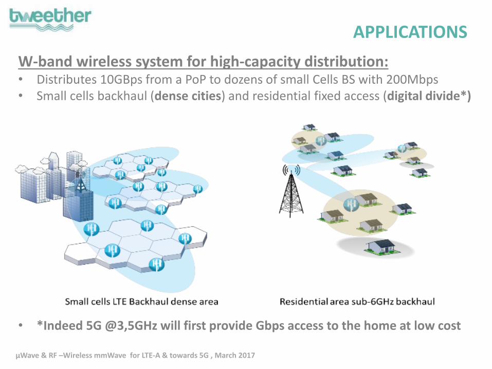
W-band wireless system for high-capacity distribution:• Distributes 10GBps from a PoP to dozens of small Cells BS with 200Mbps• Small cells backhaul (dense cities) and residential fixed access (digital divide*)
• *Indeed 5G @3,5GHz will first provide Gbps access to the home at low cost
APPLICATIONS

µWave & RF –Wireless mmWave for LTE-A & towards 5G , March 2017
Fiber EntreprisesPMP mm-wave hub Small Cell AP LTE Multi Dwelling Residential
ACCESS TIERSub6 Wireless & Ethernet
300m
BACKHAUL TIERPmP mm-wave
200Mbps1,5 -3 Km
INFRASTRUCTURE TIERFibrer optics
>Gbps10 -100 Km
PMP capacity distribution
PTP fronthaulextension to Core
3-Tiers structure for supple high capacity distribution
TWEETHER
PmP access
Tweether distributes collects and aggregates capacities to any “client” configuration. Interfaces CORE-Fronthaul and RAN on GBE
NETWORKING ARCHITECTURE
µWave & RF –Wireless mmWave for LTE-A & towards 5G , March 2017
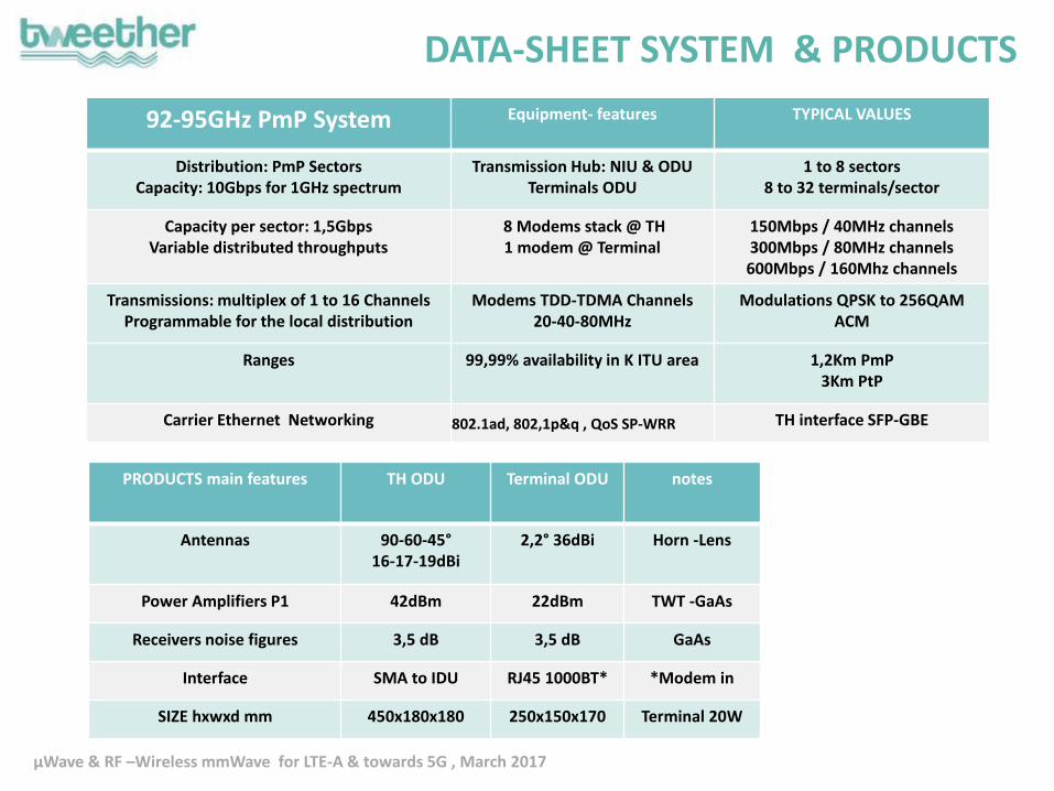
PRODUCTS main features TH ODU Terminal ODU notes
Antennas 90-60-45°16-17-19dBi
2,2° 36dBi Horn -Lens
Power Amplifiers P1 42dBm 22dBm TWT -GaAs
Receivers noise figures 3,5 dB 3,5 dB GaAs
Interface SMA to IDU RJ45 1000BT* *Modem in
SIZE hxwxd mm 450x180x180 250x150x170 Terminal 20W
DATA-SHEET SYSTEM & PRODUCTS
92-95GHz PmP System Equipment- features TYPICAL VALUES
Distribution: PmP SectorsCapacity: 10Gbps for 1GHz spectrum
Transmission Hub: NIU & ODU Terminals ODU
1 to 8 sectors8 to 32 terminals/sector
Capacity per sector: 1,5Gbps Variable distributed throughputs
8 Modems stack @ TH 1 modem @ Terminal
150Mbps / 40MHz channels300Mbps / 80MHz channels600Mbps / 160Mhz channels
Transmissions: multiplex of 1 to 16 ChannelsProgrammable for the local distribution
Modems TDD-TDMA Channels 20-40-80MHz
Modulations QPSK to 256QAM ACM
Ranges 99,99% availability in K ITU area 1,2Km PmP3Km PtP
Carrier Ethernet Networking 802.1ad, 802,1p&q , QoS SP-WRR TH interface SFP-GBE
µWave & RF –Wireless mmWave for LTE-A & towards 5G , March 2017
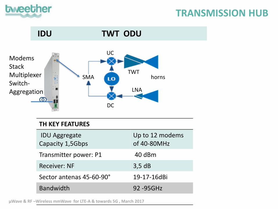
IDU TWT ODU
TH KEY FEATURES
IDU AggregateCapacity 1,5Gbps
Up to 12 modems of 40-80MHz
Transmitter power: P1 40 dBm
Receiver: NF 3,5 dB
Sector antenas 45-60-90° 19-17-16dBi
Bandwidth 92 -95GHz
TRANSMISSION HUB
SMA
DC
LNA
UC
TWThorns
ModemsStackMultiplexerSwitch-Aggregation

µWave & RF –Wireless mmWave for LTE-A & towards 5G , March 2017
TWT of the Transmisson.Hub
a)
0 1 2 3 4 5 6
20
25
30
35
40
45
50
Output power
Ou
tpu
t p
ow
er
(W)
Input power (mW)
0
20
40
60
80 phase
Ph
as
e (
de
gre
es
)b)
0 2 4 6 815
20
25
30
35
40
45
Ou
tpu
t p
ow
er
(dB
m)
Input power (dBm)
Carrier
3rd intermods
Fig. 1: a) Saturation of the output power; b) output power of the carrier and the third order
intermods as function of the input power
TWT W-band
Psat >40W >46 dBm
P1 10W 39 dBm
Gain >40 dB
PAE 40%
Bandwidth 3%
Length 350mm

µWave & RF –Wireless mmWave for LTE-A & towards 5G , March 2017
sector
T hub
Small cell BS
150 x 250 mmLow foot-print
GbEPoE
TERMINAL
Transmitter
PA gain (& driver TWT) 22 dB
PA Power P1 22 dBm
Receiver
LNA NF 3 dB
LNA Gain 20 dB
70 75 80 85 90 95 100 105 110
frequency [GHz]
0
1
2
3
4
5
6
NF
[d
B]
Pout , GP & PAE vs Pinj @93GHz
0
5
10
15
20
25
-25 -20 -15 -10 -5 0 5 10
Pinj(dBm)
0
1
2
3
4
5
6
PAE (%)
Pout
Gain
Efficiency

µWave & RF –Wireless mmWave for LTE-A & towards 5G , March 2017
TH: TWT Driver, ReceiverTerminal: Transceiver
- Wide frequency bandwidth
- Linear chain, low spurious
- Low phase noise, Low noise factor
- Low cost
CHIP SET
MMIC G P1 OIP3 S22 S11 NF Spurious Image
Unit dB dBm dBm dB dB dB dBc dBc
X 8 2 11 10 8 4 -30
UC 2 2 10 10 9 4 -6 LO -12
PA 22 22 30 10 10 6 PAE 10%
LNA 22 0 10 10 3
DC -10 0 13 15 4 -12 LO -25
Characteristics
Meets the required qualities for TH & Terminal:

µWave & RF –Wireless mmWave for LTE-A & towards 5G , March 2017
Hub Terminal
Antenna designs
Parameter Terminal Hub
Radiation pattern shape Directive Sector
Operation bandwidth (RL > 10 dB) 92 – 95 GHz 92 – 95 GHz
Realized Gain > 36 dBi > 19 dBi
HPBW Azimuth 2.2 degrees 45 degrees
HPBW Elevation 2.2 degrees 7 degrees
SIDES LOBES @ +/-2xϴ3dB <-40dB <-40dB
Small low cost antennas for the Hub and for the Terminals
LensD=115mmF=70mm
Horn L=60mm
Very low side lobesFor hihg density deployments

µWave & RF –Wireless mmWave for LTE-A & towards 5G , March 2017
Deployment model: dimensioning• Model computes* Backhaul capacity and configuration: number of hubs, sectors and modems
upon cases’ entries for dense cities or residential area and with allocated spectrum. • Dense cities mobile application inputs: population and density • Residential fix application: population and house-holds density • *beforehand models computes cells radius upon required service and cells capacity upon
spectrum
Interferences –frequency re-use 1:2– Model includes interferences computation between neighbors sectors :TH and terminals
Coverage examples: dense city of 300kha and residential of 50kha radius ~2Km
DEPLOYMENT 1/2
CELL radius 200 m
rank 5
RADIUS 1,9 km
Surface: 11 km²
a
HUB 3
BS 74
6,17 /SECTOR
R
1
2
3
3
3
4
3
1 4
3
4
3
4
1
1
2
2
2
2
4
4
4
4
4
4
4
3
4
4
4
22
3
3
3
3
1
1
2
4
4
4
4
4
4
4
4
2
3
3
4
4
2
2
3
2
3
3
3
3
0
5
5
5
5
5
5
5
5
5
5 5
5
5
3
F1
F1
F1 F2
F1 F2
F2
F1
F1
F2 F2
a
F1 F2
F2
F2 F1
F1 F1
F1
F2
F2 F1
Rf1
1
2
3
3
3
4
3
1 4
3
4
3
4
1
1
2
2
2
2
4
4
4
4
4
4
4
3
4
4
4
22
3
3
3
3
1
1
2
4
4
4
4
4
4
4
4
2
3
3
4
4
2
2
3
2
3
3
3
3
0
5
5
5
5
5
5
5
5
5
5 5
5
5
5
6
6
6
6
6
6
6
6
6
6
66
6
6
6
6
6
6
6
6
6
6
6
6
6
6
6
5
5
5
5
5
5
5
5
5
5
5
5
5
5
5
5
6
5
5
6
6
6
6
6
6
6
6
City small cells for mobile LTE-A Residential FIX 5G 3,5GHz
µWave & RF –Wireless mmWave for LTE-A & towards 5G , March 2017
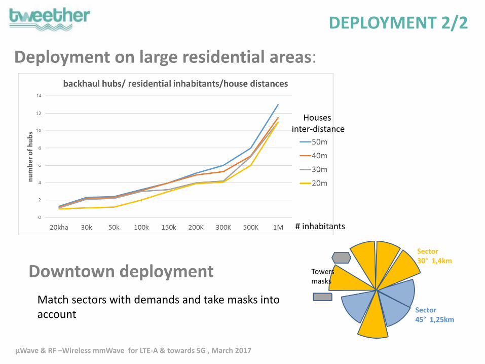
Deployment on large residential areas:
DEPLOYMENT 2/2
Housesinter-distance
Downtown deployment
# inhabitants
Match sectors with demands and take masks into account

µWave & RF –Wireless mmWave for LTE-A & towards 5G , March 2017
ECONOMY 1/2
K€
K€
TCO = 5 years OPEX + CAPEX amortized on 10yearsCapex/Mbps 55€
Dense city:Av Cost/subscribers 25€*
1/3 capex –2/3opex of TCO
Residential areas:Av Cost/subscribers 75€*
*80% penetration and 3 operators market share. Over 5 years

µWave & RF –Wireless mmWave for LTE-A & towards 5G , March 2017
ECONOMY competition 2/2
COMPARISON on 4Km² to feed 50 small cells.
PmP 6SECTORS with 8MODEMS/TH
50 links PtP

µWave & RF –Wireless mmWave for LTE-A & towards 5G , March 2017
STATUS • Integration of technology has started for RF front end
modules • Products to be assembled and tested Q3 2017• Installation and networking in Valencia Q4 2017
• Field test and demonstrations Q1 2018
Status and Field Trial
µWave & RF –Wireless mmWave for LTE-A & towards 5G , March 2017
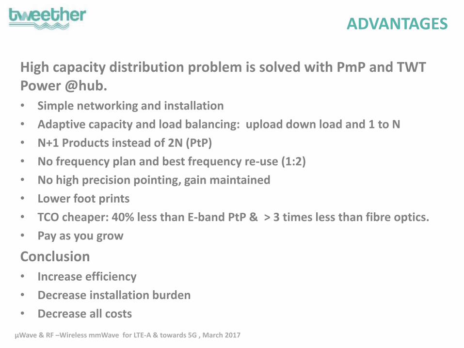
High capacity distribution problem is solved with PmP and TWT Power @hub. • Simple networking and installation
• Adaptive capacity and load balancing: upload down load and 1 to N
• N+1 Products instead of 2N (PtP)
• No frequency plan and best frequency re-use (1:2)
• No high precision pointing, gain maintained
• Lower foot prints
• TCO cheaper: 40% less than E-band PtP & > 3 times less than fibre optics.
• Pay as you grow
Conclusion• Increase efficiency
• Decrease installation burden
• Decrease all costs
ADVANTAGES

µWave & RF –Wireless mmWave for LTE-A & towards 5G , March 2017
Thank you for the attention!
Follow TWEETHER project on
www.tweether.eu
@h2020tweether
The project has received funding from the European Union’s Horizon 2020 research and innovation
program under grant agreement no 644678
µWave & RF –Wireless mmWave for LTE-A & towards 5G , March 2017
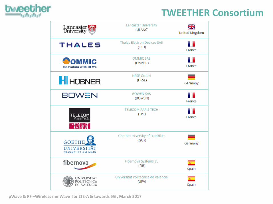
TWEETHER Consortium

µWave & RF –Wireless mmWave for LTE-A & towards 5G , March 2017
mm Waves: the solution to distribute capacity at much
lower cost and burden than fibre
MicrowavesLimited frequency band
Millimetre wavesMulti-GHz frequency band
PtP
O2
P
t
P
P
t
P
6 G
Hz
11
GH
z
18
GH
z
23
GH
z
26
GH
z2
8 G
Hz
38
GH
z4
2 G
Hz
60
GH
z
70
GH
z
80
GH
z
Traditional Microwave Frequencies Millimetre Wave FrequenciesNLOS
90
GH
z
V band strongly impacted by O2 absorption peak and suitable only for PtP link
E band licensed for PtP
W-band
(92-95 GHz)