wads 2003 workshop on software architectures for ... · wads 2003 workshop on software...
TRANSCRIPT

WADS 2003 Workshop on
Software Architectures for Dependable Systems
ICSE’03 International Conference on Software Engineering
Portland, Oregon May 3-11, 2003


Preface
Architectural representations of systems have shown to be effective in assisting the understanding of broader system concerns by abstracting away from details of the system. The dependability of systems is defined as the reliance that can justifiably be placed on the service the system delivers. Dependability has become an important aspect of computer systems since everyday life increasingly depends on software. Although there is a large body of research in dependability, architectural level reasoning about dependability is only just emerging as an important theme in software engineering. This is due to the fact that dependability concerns are usually left until too late in the process of development. In addition, the complexity of emerging applications and the trend of building trustworthy systems from existing, untrustworthy components are urging dependability concerns be considered at the architectural level. Hence the questions that the software architecture and dependability communities are currently facing: what are the architectural principles involved in building dependable systems? How should these architectures be evaluated?
By bringing together researchers from both the software architectures and the dependability communities, this workshop makes contributions from dependability more visible within the software engineering community and vice-versa, thus helping to build strong collaboration possibilities among the participants. The workshop provides software engineers with systematic and disciplined approaches for building dependable systems, as well as allows further dissemination of the state of the art methods and techniques.
During ICSE 2002 we organized the first workshop, which was a success (http://www.cs.ukc.ac.uk/wads/), and a LNCS volume has been edited that combines the state-of-the-art articles in the area. The aim of this Second Workshop on Software Architectures Dependable Systems is once again to bring together the communities of software architectures and dependability to discuss the state of research and practice when dealing with dependability issues at the architecture level.
We have received 20 submissions mainly from academic contributors. Each paper was reviewed by 3 members of the Program Committee, and a total of 14 papers have been accepted. We are thankful for the support and dedication of the Program Committee towards making this workshop a success. The Program Committee consisted of:
Jean Arlat, France Andrea Bondavalli, Italy Jan Bosch, The Netherlands David Garlan, USA Paola Inverardi, Italy Valérie Issarny, France Philip Koopman, USA Nicole Levy, France Nenad Medvidovic, USA Dewayne E. Perry, USA Debra Richardson, USA Cecília Rubira, Brazil William Scherlis, USA Francis Tam, Finland Kishor S. Trivedi, USA Frank van der Linden, The Netherlands Paulo Veríssimo, Portugal
We look forward to an interesting and stimulating workshop.
Rogério de Lemos, Cristina Gacek, and Alexander Romanovsky


Table of Contents
Perspective-Based Architectural Approach for Dependable Systems……………………………………….…1 S. X. Liang, J. Puett, Luqi
Reliability Support for the Model Driven Architecture……………………...……………………………….…7 G. N. Rodrigues, G. Roberts, W. Emmerich, J. Skene
FaTC2: An Object-Oriented Framework for Developing Fault-Tolerant Component-Based Systems….…13 F. J. C. de Lima Filho, P. A. de C. Guerra, C. M. F. Rubira
A Dependable Real-Time Platform for Industrial Robotics……………...…...……………………….………19 G. Mustapic, J. Andersson, C. Norstrom
A Framework for Using Component Redundancy for Self-Optimising and Self-Healing Component Based Systems………………………………………….……...…...……….………………….……25 A. Diaconescu, J. Murphy
Elements of the Self-Healing System Problem Space………….……...…...…….……………….….….………31 P. Koopman
Dependability Analysis Using SAM………………….……...…...……………………..………………….….…37 T. Shi, X. He
Formalizing Dependability Mechanisms in B:From Specification to Development Support…………..……43 F. Tartanoglu, V. Issarny, N. Levy, A. Romanovsky
Layered Dependability Modeling of an Air Traffic Control System..………………..…………………….…50 O. Das, C. M. Woodside
Design for Verification: Enabling Verification of High Dependability Software - Intensive Systems…..….56 P. C. Mehlitz, J. Penix, L. Z. Markosian
Toward a Framework for Classifying Disconnected Operation Techniques……..………………….……….59 M. Mikic-Rakic, N. Medvidovic
An Architecture for Configurable Dependability of Application Services………..………………..…………65 M. Tichy, H. Giese
An Approach to Manage Reconfiguration in Fault-Tolerant Distributed Systems………………..…………71 S. Porcarelli, M. Castaldi, F. Di Giandomenico, A. Bondavalli, P. Inverardi
Dependability in Software Families………………….……...…...……………………..………………….….…77 F. van der Linden


Perspective-based Architectural Approach for Dependable Systems
Sheldon X. Liang, J. Puett, Luqi
Software Engineering Automation Center US Naval Postgraduate School
{xliang, jfpuett, luqi}@nps.navy.mil
Abstract
Explicitly architecting dependable systems inevitably involves establishing consensus among different stakeholders' concerns and then anchoring the design on architectural components that provide robustness. The goal is to architect evolvable systems upon which users can reasonably rely on receiving anticipated services. Unfortunately, there are few established approaches for rapidly prototyping architecture to identify dependable architectural components during the early stakeholder requirements resolution phases of software design. This paper presents a perspective-based architectural (PBA) approach process using rapid prototyping to build dependable architectures using compositional patterns. The approach is achieved through explicit architecting and system composition to provide a set of rules governing the system composition from coarser-grained dependable components. The approach provides a rationale for treating dependability as a set of semantic constraints localized on compositional patterns.
1. Introduction Building dependability into the architectural design
aims at attaining the benefits of reduced cost and increased quality. The central idea is that dependable architectures in large, complex, evolving systems will provide their users with a reasonable assurance that the system will deliver the services promised. Explicitly architecting such systems requires identifying and resolving different stakeholders' concerns. For instance, the architect may have to resolve the inherit conflicts between a user stakeholder that is concerned with achieving a particular computational requirement and an implementer stakeholder that may be concerned with achieving systematic long-term evolution of the system. Perspective-based architectural design [1-4] allows some resolution between these perspectives.
The difficulties in engineering software-intensive systems are further exacerbated by requirements uncertainty, dynamic organizational structures (and concerns), and the requirement for rapid application development. Engineering dependable systems involves three crucial aspects: 1) accurately identifying all customer requirements, 2) resolving customer
requirement conflicts within the context of different customer perspectives, and 3) verifying that the resulting system satisfies customer intent (and if not, correcting the requirements and the system).
A number of techniques, frameworks, and approaches have emerged to address the problems in engineering software-intensive systems. Widely embraced efforts include rapid system prototypes [5-6], software architectures [7-11], and component techniques [12-14]; all of which focus on composing software systems from coarser-grained components. Rapid system prototyping is useful in effectively capturing and resolving uncertainty about requirements and providing computational visibility [6]. Component techniques assume a homogeneous architectural environment in which all components adhere to certain implementation constraints (e.g., design, packaging, and runtime constraints). They are unalterably associated with derivational implementation with little concern of the perspectives of the customer or architect [8-10]. Software architecture approaches typically separate computation (components) from interaction (connectors) in a system. However, the current level of understanding and support for connectors has been insufficient, so that connectors are often considered to be explicit at the level of architecture, but intangible in the system implementation [9-10]. Several sources have recommended the use of architecture views [1, 2]. Yet, while they provide guidance on how architecture should be represented, they generally do not provide a prototyping process for the early development of the artifacts that are used in that representation [3-4].
The rapid prototyping of architectural components shows promise in acquiring accurate and timely requirements and in establishing appropriate compartmentalization of functionality [2-4]. To reduce the amount of re-certification effort required after each requirement change, the approach presented in this paper helps to maintain the assurance of dependability as the system evolves by combining rapid prototyping with explicit architecting so that the system's architecture is based on properties that are invariant with respect to system requirements changes. This research integrates requirements validation techniques and stakeholder perspective resolution into a single model of explicit architectural composition.

2. Overview of the Approach Fig. 1 depicts the PBA approach embodied in three
perspectives: computational activity, compositional architecture and derivational implementation. Starting by rapid prototyping the user’s informal needs, an initial prototyping model is created that represents the computational activity needed to implement the operational concept. Continued analysis and refinement of the prototype then derives the explicit architecture from which it is possible to extract valuable architectural properties. Compositional architecture is then explicitly built under the support of compositional patterns, and the generation of application framework is driven by both prototyping and architecting documentations. Next, PBA composers are applied to derive PBA components.
Fig 1 Synthesizing Approach
For each perspective design artifact, a computer-aided foundation is provided with significant formulated attributes enabling automated analysis, reasoning and code/framework generation. For instance, the computational activity captures the activities and information flows that will accomplish the operational concept (e.g., real-time support is the foundation for hard real-time systems [5]); the compositional architecture details what kinds of rules (patterns) are used to govern the interactions among components (e.g., compositional patterns [8,11] and design inspection [15-17] support semi-automated architecture generation); and the derivational implementation identifies physical components and connectivity that will be instantiated to carry out the computational activities (e.g., based on PBA composers [18]). Thus, compositional architecture bridges gaps between the computational and derivational artifacts (user and implementer perspectives).
3. Perspective-based Architecting Central to the PBA approach, compositional patterns
provide principles for guiding the design and evolution of system architecture and can be treated as architectural elements governing system composition from coarser-grained components. The transitional process is
embodied in three perspective designs.
3.1 Computational activity Computational activity accounts for the customer
perspective concerns of computation and interconnection. This perspective addresses system requirements by capturing three kinds of formal arguments: components from which the system is built, interconnections enforcing interactions among them, and constraints on both components and interconnections:
P computation = [Cc, I, Ct (Cc, I)] Where Cc is the set of conceptual components hierarchically decomposed, I is the set of interconnections among components, Ct (Cc, I) is the set of constraints localized on components and their interconnections, respectively.
Fig. 2 Computational Responsibility and Properties
The constraints on components have properties of decomposability (representing the hierarchical level at which the constraint is implemented) and granularity (representing the logical packaged complexity of the component). Granularity is an important factor for constructing complex systems because well-grained components are helpful not only to increase productivity but also to improve understandability, reliability and maintainability. As illustrated in Fig. 2, a schema is introduced for PBA components, which identifies the granularity and decomposability of each level of computational responsibility.
3.2 Compositional architecture Compositional architecture accounts for the architect's
perspectives of explicit treatment of system composition and architecture with constraints localized on compositional patterns. Detailing what kinds of rules (patterns) are used to govern interactions among components and how quantitative constraints are associated with the patterns, this perspective addresses what kinds of interactions are applied among components and how to associate constraints with compositional patterns. This perspective is represented as follows:
P composition = [Cc ⇒ R, Ro─S/P→Ri, Ct (R, S, P)]
CSCS CSCS: Computer Software Complex System is a top - level component that undertakes global a ctivity in distributed and concurrent collaboration .
CSCI CSCI: Computer software Configuration Item is a 1 st level component that undertakes a specific mission and is a part of the top-levelcollaboration (CSCS)
CSCC CSCC: Computer Software Common Component is a 2 nd level component that undertakes a specific function and comprises the 1 st level mission (CSCI)
CSCUCSCU:Computer Software Computing Unit is a 3 rd level component that undertakes a specific task and comprises the 2 nd level function (CSCC).
Collaboration
Mission
Function
Task
Computational Component Systematic Responsibility Granularity Decomposability
EASYC Composers
Compositional Patterns
Prototype (Model)
Refine (Coding)
System Architecture
Component Evolution
Construct (Prototype)
Functional Behavior Real-time Constraints
Architectural Properties
Real-time Support
Computational Activity
User’s Informal Needs
Highly Dependable
Systems
Operational Concept
Rules / patterns for Interconnections
Derivational Implementation
Compositional Architecture
Components and Connectivity
Design Inspection
Generating (Framework)
PBA

Where Cc ⇒ R is the set of roles extracted from conceptual components. Ro─ S/P→Ri is the set of compositional patterns: Ro (output/producer) interacts with Ri (input/consumer) via architectural styles S while complying with communicatory protocols P. Ct(R, S, P) is the set of constraints localized on roles, styles, and protocols, respectively. Constraints on interactions further localized on
architectural styles are embodied in such properties as composability and heterogeneity. Composability represents the hierarchical composition of architecture (i.e., an entire architecture becomes a single component in another larger architecture). Heterogeneity represents the diverse ways components interact with each other. Heterogeneity is inevitable in complex systems because diverse components or systems will have to work and interact together. In Fig. 3, a compositional coupling schema is introduced for PBA approach.
Fig. 3 Compositional Coupling and Properties
3.3 Derivational implementation Derivational implementation accounts for the
implementer's perspectives of component derivation and connectivity. This perspective addresses what kinds of components are needed to carry out computational activity, what connectivity is needed between the components and how to glue the components to specific roles. This perspective is represented as follows:
Pderivation = [R ⊃Cp, (Cp Ro)─S/P→(Ri Cp), Ct (Cp S, P)]
Where R ⊃ Cp is the set of physical components derived from the
associated role. Cp R (its peer Ri Cp) is the set of instantiated components that are glued to associated roles. Ct(Cp, S, P) is the set of constraints localized on physical components, styles, and protocols, respectively. Constraints on components are embodied in such
properties as connectivity (representing the way components are derived from the related role) and evolvability (representing the evolution from roles to components). Interactive roles are represented as generalized role wrappers (GRWs) (an abstract class) to support component evolution through sub-typing and refinement. As illustrated in Fig. 4, the GRWs defined in PBA composers introduce derivational gluing to refer to connectivity and evolvability.
Fig. 4 Derivational Gluing and Properties
3.4 Automated transitional process Starting with a prototyping model in the computational
activity perspective, a transitional process is formed from computational activity, through compositional architecture, to derivational implementation. Two kinds of architectural elements evolve: PBA composers and PBA components. Under the support of automated software tools, two key mappings are used to bridge the gaps between perspectives: explicit architecting via compositional patterns and physical evolution via PBA composers. PBA approach is associated with support tools such as Prototyping Analyzer, Pattern Selector, Framework Generator, and Component Evolver [5,8]. Fig. 5 illustrates this transitional process.
P computation P composition P derivation Cc Cc ⇒ R R ⊃Cp I Ro─S/P→Ri (Cp R)─S/P→(R Cp)
Ct(COM, INT)
Explicit Architecting via
Compositional patterns Ct (R, S, P)
Physical Derivation via
PBA composers Ct (Cp, S, P)
Fig. 5 Transitional Process between Architectural Perspectives
O2 NH3 H2O
Water_Flow
Display_status
Drain Inlet Feeder
F_Time
Repository
Adjusting Listener Feeding Listener
Sampler
Source
Sensor
Adjusting Announcer Feeding Announcer
COM1 COM2
P
Sro ri
glue glue
COM1 COM2
P
Sro ri
glue glue
COM1 COM2
P
Sro ri
glue glue
Prototyping Analyzer Pattern Selector Framework Generator Component Evolver
IDI I DI: Interoperable - Distributed Interaction is used for composing CSCS from CSCI components to enforce distributed interactive collaboration
LCI LCI: Loose- Coupled Interaction is used for composing CSCI from CSCC compo nents to encourage flexible configuration with minimal communication between components
TCI TCI: Tight -Coher ent Interaction is used for composing CSCC from CSCU components to emphasize independent partition of components with high internal complexity
Distributed
Loose
Coherent
Compositional Interactive Architectural Coupling Heterogeneity Composability
IsA IsA: “is a ” connectivity let s a system component be derived from the correspond ing role wrapper and then extend s its behavioral compu tation.
ToA ToA: “to a” connectivity let s a system component associate with the corresponding role wrapper and then refine s its behavioral computation.
HasA HasA: “has a” connectivity lets a systemcomponent aggregate one or more of thecorresponding role wrapper and then refinesits behavioral computation.
Extension
Import
Assembly
Derivational Physical Componential Gluing Connectivity Evolvability

Explicit architecting of the computational activity starts with assigning components with specific roles. According to the architectural styles, related interactive roles and communicatory protocols can be determined so that suitable compositional patterns can be selected and applied to govern the interconnections among the roles. According to the assignment of which components play which specific roles, the components will be derived from the associated role facility. After being derived, the components will be instantiated and then glued to the associated roles by the PBA configuration.
A PBA composer is designed as a generic package-like architectural entity that includes two kinds of GRWs: one is for the "interactive producer" and the other is for the "interactive consumer." GRWs provide adherence to restricted, plug-compatible interfaces for interaction and provide the template of behavior that components are expected to refine. The physical connectivity between a component and a role is implemented by refining or overriding the restricted, plug-compatible interfaces defined by the GRW [11, 18].
4. Dependable Compositional patterns Compositional patterns provide a set of rules that
govern the interactions among components with localized constraints. They are characterized by three kinds of formulated arguments: interactive roles, architectural styles, and communicatory protocols.
Fig. 6 Compositional pattern for interconnections
Fig. 6 depicts a compositional pattern. For a given interaction between two components (COM1, COM2), both are assigned to play specific roles ro and ri in the specific compositional pattern. An architectural style s specifies how ro (output / producer) interacts with ri (input / consumer), while communicatory protocol p builds a specific channel for message transportation during the interaction. More specifically, in order to construct the components as autonomous entities, roles in the compositional pattern are deputized for the components in dealing with interaction while the associated components are mainly concerned with their functionality (computation separated from interaction). The pattern also provides a means for gluing a specific component to a role.
By mathematically defining the compositional patterns, it is possible to translate, localize, and analyze them using automated CASE tools. Compositional patterns involve three sets: R representing interactive roles, S
representing architectural styles, and P representing communicatory protocols. Examples include:
R = { S = { P = { Caller, Definer, Announcer, Listener, Outflow, Inflow, Source, Repository, Read, Writer, … }
Explicit-invocation, Implicit-invocation, Pipe-filter (Pipeline), Repository-centric, Blackboard, … }
Message-passing, Event-broadcast Data-stream, Sampled-stream Shared-data, … }
Regardless of any constraint, a composition is defined as an interaction between two roles (e.g., Caller and Definer) via an architectural style (e.g., explicit-invocation), while complying with a communicatory protocol (e.g., message-passing). So, the Cartesian product R х S х P х R enumerates all possible compositions C, represented as follows:
C (R, S, P)={ ro─s/p→ri | ro, ri ∈ R, s∈ S, p∈ P }
Where ro─s/p→ ri represents interaction between ro and ri via a style s while complying with a protocol p.
Applying specific constraints on compositions develops sophisticated compositional patterns. While GRWs provide adherence to restricted, plug-compatible interfaces for interaction and template of behavior for computation, the components derived from GRWs will specify, refine or override the template. In this way, interactions are separated from computations.
Compositional patterns CP are the relation on the Cartesian product of compositions with the constraints reasonably localized on roles, styles and protocol:
CP(R, S, P) = {GRW(ro)─s/p→GRW(ri) | ro, ri∈ R, s∈ S, p∈ P, Ct( ro, s, p, ri) }
Where GRW(r) abstracts the role r as a GRW that separates interaction from computation (the GRW "provides" while the component "performs"). ─s/p→ represents interaction between ro and ri via a specific style s while complying with a specific protocol p. Ct(ro, s, p, ri) represents localized constraints.
4.1 Example of compositional patterns Compositional patterns can be implemented as
composers, an explicit architectural element. They can be organized in a reusable composer library that provides the evolutionary foundation for component derivation. Fig. 7 gives the typical composer Pipeline that exhibits dependable architectural properties (e.g., loose component coupling, asynchronous communication, and data buffering). The two sides interconnected by the composer are the Outflow and Inflow roles, respectively. Outflow deputizes the producer to output the data, while Inflow deputizes the consumer to input the data via Pipeline. The formal Pipeline composer provides two generic parameters for enhancing reusability: transported Data (a basic item for dataflow) and buffer Size (a data transportation buffer).
COM1 COM2 P
S ro ri
glue glue

This example provides a template for GRWs. With respect to behavioral computation of components, the CSP-based semantic description provides not only synchronous constraints but also asynchronous control transits. Both Output and Input are designed as exclusive procedures (execution guards are used to coordinate concurrent synchronization). Reference timing constraints [5-6], the role of Outflow is subjected to a maximum execution time (met) while Inflow is subject to a maximum response time (mrt). Both met(100) and mrt(100) are translated as asynchronous control transits for runtime monitoring of the real time constraints. " " represents an asynchronous operation. When outputting produced data onto the given pipeline, Outflow must be synchronized within a met(100) otherwise, an exception is triggered.
composer Pipeline is generalized type Data is private; Size : Integer : = 100; style as <#pipe-filter#>; protocol as <#dataflow-stream#>; wrapper role Outflow is
port procedure Output(d: Data); procedure Produce(d: Data) is abstract; computation Produce (d); *[ Output (d) Produce (d) met(100) exception; ] end Outflow; role Inflow is port procedure Input(d: Data); procedure Consume(d: Data) is abstract; computation *[ Input (d) Consume (d) mrt(100) exception; ] end Inflow;
collaboration (P : Outflow; C : Inflow) P•Produce(d);
*[ P•Output(d) P•Produce(d) C•Input(d) C•Consume (d)] end Pipeline;
Fig. 7 A Formal composer for Pipeline The collaboration portion of the composer description
will generate topological configurations that are connected graphs of components and composers. In concert with models of components and composers, configurations enable assessment of the autonomous and concurrent aspects of an architecture (such as the potential for deadlocks, starvation, reduced performance, reliability, security, etc.). Configurations also enable concurrent execution immediately after the roles are glued with the instances of corresponding components.
4.2 Substantiated interconnection It used to be that interconnections in the architecture of
a software system were annotated as a series of “box-line-box” diagrams [8-10]. Over time, this annotation has become much richer (for instance, the use of Architecture Description Languages (ADLs)) in order to more precisely capture and communicate more complex ideas related to interconnection. PBA continues in this vein by substantiating the interconnections among components so that large, complex architectures of
systems can be built, dealing with following four aspects: • Dependable composers by which interaction among
components are promoted, • Heterogeneous forms by which communication during
interaction can be established. • Topological connectivity that guides the connected
configuration of components, and • Constraint localization that governs interconnections
by associating constraints on patterns Dependable composers are used to implement
compositional patterns by analyzing interactive roles of interconnected components in the prototyping model. Heterogeneous forms are associated with architectural styles and the way information is transported and refers to as communicatory protocols in compositional patterns. Constraint localization is presented next.
Topological connectivity simplifies the interconnection among components and comes in the following forms: • Fork (1~N): single producer to multiple consumers • Merge (N~1): multiple producers to single consumer • Unique (1~1): single producer to single consumer • Hierarchy: external1 producer to interact with the internal1
consumer, and vice versa.
Fig. 8 illustrates how to use a composer to implement Fork between one producer and more than one consumer.
Fig. 8 Fork Connectivity with one PBA composer
4.3 Dependability as a set of Constraints In this case “localization” represents the abstraction of
dependability, its translation to quantitative constraints, and the handling of these constraints applied (localized) in the design, construction, and evolution of a software-intensive system. In order to achieve high confidence in the dependability of a system there must be a systematic method for expressing the dependability objectives via measurable constraints associated with the subsystems of the architecture. In a macro view, dependability can be abstracted as availability, reliability, safety, confidentiality, integrity and flexibility [15-17]. How these qualitative global requirements translate into quantitative constraints becomes crucial. Which dependable properties need translating and how they are localized on compositional patterns are the questions that have to be answered.
1 External and internal refer to hierarchical decomposition. For a given hierarchical level of decomposition, a component in the current level is external to a component in a lower level, while the latter is the internal to the former.
Component
Composer

Dependability Translation Constraints Localization Patterns
• Availability • Reliability • Security • Integrity • Flexibility
• Consistency • Compatibility • Granularity • Heterogeneity • Real time • Synchronization
• Role • Style • Protocol
Fig. 9 Localization of Dependability
Fig. 9 shows a framework of localization applied to dependability. With respect to translating dependability and localizing the semantic constraints on the compositional patterns, the handling of real-time constraints provides a good example. Reliability of the time-critical system may be embodied as an immediate reply of a particular component, under a given request, within an met, or as a data stream between components performed within a specific latency [5]. First, this time-critical reliability should be translated into timing constraints met and latency (two quantitative constraints). Both are associated with the patterns referring to the role and protocol, respectively. met requires computation of the role (the component acts) and must be executed within a specific amount of time (a hard real-time constraint). The latency constrains the maximum delay during data transportation within the protocol. These timing constraints can be also verified by runtime monitoring and correctness assurance [15-17]. Dependability of the system would be translated into in the form of maximum execution time or latency of the data stream communication between components as shown in Fig. 10.
composer Pipeline is generalized … role Outflow is port procedure Output(d: Data); procedure Produce(d: Data) is abstract; computation Produce (d); *[ Output (d) latency(60) Produce (d) met(100)
latency-signaled LAT-EXCEPTION met-signaled MET-EXCEPTION
] end Outflow; … … end Pipeline;
Fig. 10 A Formal composer for Pipeline
Procedure Output can be treated as execution guard that is tied to the communication protocol, so latency is associated with to the protocol by Output (d) latency(60). When executing Output is beyond the latency, the asynchronous control will set latency-signaled and abort current execution, and then raise LAT_EXECPTION. Similarly, met is directed to the procedure Produce by Produce (d) met(100). When executing Produce is beyond the met limitation, the asynchronous control will set met-signaled and abort current execution, and then raise MET_EXCEPTION.
5. Conclusion Explicitly architecting software-intensive systems
provides the promise of faster, better, cheaper systems. In order to consistently engineer dependable software-intensive systems, the PBA approach provides a process that uncovers perspective concerns of different stakeholders, and increases the effectiveness of requirements validation techniques. Because PBA approach can be used to localize and quantify invariant architectural constraints (such as "dependability" in the example above) it will also reduce the amount of re-certification effort required after each requirement change. The PBA approach illustrates that with automated tool support, the prototyping of software architecture can be used to identify and resolve conflicting stakeholder perspectives and develop reliable, dependable, consistent software-intensive systems.
References [1] C. Hofmeister, R. Nord, D. Soni. Applied Software
Architecture. Addison-Wesley, 2000. [2] IEEE Standard Board, Recommended Practice for
Architectural Description of Software-Intensive Systems (IEEE-std-1471 2000), September 2000.
[3] H. Alexander, et el, C4ISR Architectures: I. Developing a Process for C4ISR Architecture Design. Systems Engineering, John Wiley and Sons, Inc., Vol. 3 No. 4, 2000.
[4] W. Lee, et el, Synthesizing Executable Models of Object Oriented Architectures. Proc. Formal Methods in Software Engineering & Defence Systems. Adelaide, Australia, 2002.
[5] Luqi, M. Ketabchi, A computer-Aided Prototyping System, IEEE Software, March 1988.
[6] Luqi, Ying Qiao, Lin Zhang, Computational Model for High-Confidence Embedded System Development, Monterey workshop 2002, Venice, Italy, Oct 7-11, 2002.
[7] M. Shaw, D. Garlan, Software Architecture: Perspectives on an Emerging Discipline. Prentice Hall, Inc., 1996.
[8] Andrew P., Systems Integration and Architecting: An Overview of Principles, Practices, and Perspectives, System Engineering, John Wiley and Sons, Inc., 1998.
[9] N. R. Mehta, N. Medvidovic. Towards a Taxonomy of software Connectors. Proc. ICSE, Limerick Ireland, 2000.
[10] N. Medvidovic, Taylor, A classification and comparison framework for software architecture description languages. IEEE Transactions on Software Engineering, 2000, 26(1).
[11] X Liang, Event-based implicit invocation decentralized in Ada, ACM AdaLetters, March, 2002.
[12] Sessions N., COM and DCOM: Microsoft's Vision for Distributed Objects. John Wiley & Sons, Inc., NY, 1997.
[13] OMG/ISO Standard, CORBA: Common Object Request Broker Architecture, http://www.corba.org/.
[14] Sun Microsystems, Inc. Java 2 Enterprise Edition Specification v1.2. http://java.sun.com/j2ee/.
[15] E. M. Clarke (CMU), R. P. Kurshan (Bell Lab). Computer-Aided Verification, Feb. 17, 1996.
[16] James C. Corbett, et el, Bandera: Extracting Finite-state Models from Java Source Code, Proc of the ICSE 2000.
[17] M. Kim, et el, Monitoring, Checking, and Steering of Real-Time Systems, 2nd Intl. Workshop on Run-time Verification. Copenhagen, Denmark, July 26, 2002.
[18] X Liang, Z. Wang. Omega: A Uniform Object Model Easy to Gain Ada's Ends, ACM AdaLetters, June, 2000.

Reliability Support for the Model Driven Architecture ∗
Genaina Nunes Rodrigues, Graham Roberts, Wolfgang Emmerich and James SkeneDept. of Computer ScienceUniversity College London
Gower Street, London WC1E 6BT, UK{G.Rodrigues|G.Roberts|W.Emmerich|J.Skene }@cs.ucl.ac.uk
Abstract
Reliability is an important concern for software dependabil-ity. Quantifying dependability in terms of reliability canbe carried out by measuring the continuous delivery of acorrect service or, equivalently, of the mean time to failure.The novel contribution of this paper is to provide a meansto support reliability design following the principles of theModel Driven Architecture(MDA). By doing this, we hopeto contribute to the task of consistently addressing depend-ability concerns from the early to late stages of softwareengineering. Additionally, we believe MDA can be a suit-able framework to realize the assessment of those concernsand therefore, semantically integrate analysis and designmodels into one environment.
1. Introduction
Component-based development architectures (CBDA) areincreasingly being adopted by software engineers. Thesearchitectures support distributed execution across machinesrunning on different platforms (e.g. Unix, Windows). Ex-amples of component models include Sun’s Enterprise JavaBeans (EJB), OMG’s CORBA Component Model (CCM)and Microsoft’s .NET. Additionally, CBDAs rely on theconstruction and deployment of software systems that havebeen assembled from components [3].
One of the advantages of applying a component-basedapproach is reusability. It is easier to integrate classesinto coarse-grained units that provide one or more clearlydefined interfaces. However, the lack of interoperabilityamong diverse CBDAs may be one of the major problemsthat hinders the adoption of distributed component tech-nologies. Once a platform has been chosen and the systemhas been developed, porting to a different platform becomestroublesome.
∗This research is partially supported by CAPES and the EuropeanUnion under grant IST-2001-34069
To fill the gap, the OMG has focused on paving the wayto provide CBDAs interoperability standards through theModel Driven Architecture (MDA). Essentially, ”the MDAdefines an approach to IT system specification that sepa-rates the specification of system functionality from the spec-ification of the implementation of that functionality on aspecific technology platform” [9]. To accomplish this ap-proach, MDA structures the system into key models: thePlatform Independent Models (PIMs) and the Platform Spe-cific Models (PSMs). While a PIM provides a formal spec-ification of the structure and function of the system that ab-stracts away technical details, a PSM expresses that speci-fication in terms of the model of the target platform. Basi-cally, PIMs are mapped to PSMs when the desired level ofrefinement of PIMs is achieved.
The Unified Modeling Language (UML) is the core el-ement to represent those models. According to the OMG,UML supports the formalization of an abstract, though pre-cise, models of the state of an object, with functions and pa-rameters provided through a predefined interface [9]. Fur-thermore, UML models facilitate the assessment of a designin the early stages of software development, when it is eas-ier and cheaper to make changes.
The defined and standard structure of MDA would seemsuitable to address software dependability, in that the MDAdesignates the system function as required by the stakehold-ers. Issues such as reliability, safety, security and availabil-ity comprise software dependability [8, 12]. However, thereis no standard representation for dependability in MDAmodels. During the software execution this can lead to sit-uations not foreseen in the platform models.
Reliability assurance is an important concern in softwaredependability. Quantifying dependability in terms of relia-bility can be carried out by measuring the continuous deliv-ery of correct services or equivalently, of the mean time tofailure [4]. A system can be considered reliable if it per-forms at a constant level, as the stresses on that systemchange. For example, if a0 request takes 10 ms to com-plete with one user, then it takes the same time to process

the same request with 1000 concurrent users.To overcome the lack of dependability concern in the
current MDA specification, we propose to explicitly tacklethis problem in the levels of abstraction suggested byOMG’s MDA. We believe it is feasible to accomplish thistask using the standard meta-modeling approach of MDAand specifications, such as the work in [10], as sources toachieve this goal. Our focus on dependability at the momentis reliability. To guarantee and assess reliability propertiesof software systems using the MDA approach, we plan toachieve reliability in such a way that it would be specified inthe early stages of software architecture design. In this way,we aim to provide reliability in a platform-independent way.In the context of MDA and current distributed component-based architectures, early reliability assessment is importantas the software architecture design is specified in the con-text of software development.
The novel contribution of this paper is to provide ameans to support reliability design following the principlesof MDA. By doing this, we hope to contribute to the task ofconsistently carrying out dependability concerns from theearly to the late stages of software engineering. Besides,MDA appears to be a suitable framework to realize the as-sessment of those concerns and therefore, semantically in-tegrate analysis and design models into one environment.
In this position paper, we elaborate our approach on howthe provision of reliability can be suitably realized through astandard model-driven architecture approach. In Section 2,we present the related work targeting reliability support andanalysis in the CBDA scenario. In Section 3, we showhow we plan to provide reliability modeling in MDA andthe steps to be followed to accomplish this goal. In Sec-tion 4, we provide a sample scenario of how our approachaddresses reliability support in MDA. Finally, Section 5summarizes our contribution and discusses future work to-wards achieving standard reliability support from designingmodels to programatic interfaces.
2. Related Work
The work described in [1, 2, 7] looks at part of the problemswe identify in our work, in terms of addressing dependabil-ity concerns in the early stages of software development.We can basically find in these works analysis techniques tovalidate design tools based on UML.
However, they differ from our approach in some impor-tant aspects. Primarily, they do not conform to the prin-ciples stated by MDA. MDA uses the straightforward ap-proach through the concepts of mapping models among dif-ferent platforms. Therefore, we believe that MDA offersa suitable environment to consistently integrate the analy-sis and design of dependability issues, and from design toimplementation. [1] provides a useful transformation tech-
nique to automate dependability analysis of systems de-signed using UML. Nevertheless, to properly contemplatedependability in all stages of the software engineering pro-cess, we believe that one of the main concern is to provide aunified semantic between the analysis and the design mod-els.
Another approach to address software dependability is toprovide mechanisms to improve reliability of software af-ter it has been implemented. Works such as [5] use testingtechniques to identify faults in the software that are likelyto cause failures. Although they carry out an important re-search agenda, we believe that is cheaper to design and eval-uate dependability concerns in the early stages of softwareengineering processes . Besides, levels of abstraction likethe one expressed by the PIM and PSM models of MDAseems to be necessary in a scenario where each of the ex-isting CBDA holds distinct mechanisms to support depend-ability.
A meta-model is a model of a language expressed usinga modeling technique. This feature in UML allow us to ex-press the design and analysis domains naturally, using theconcepts inherent to these domains. Moreover, this facil-ity permits to map the behavior of distributed componentarchitectures into a domain knowledge keeping the seman-tics of the modeling requirements of UML. Following thisprinciple, our approach to meta-modeling using the UMLlightweight extension mechanisms, i.e. profiles, is consis-tent with the official MDA white paper [9], which definesbasic mechanisms to consistently structure the models andformally express the semantics of the model in a standard-ized way. Moreover, the profiles define standard UML ex-tensions to describe platform-based artifacts in a design andimplemented model. For example, the UML Profile forEJB [6] supports the capture of semantics expressible withEJB through the EJB Design Model and the EJB Implemen-tation Model. Although currently cannot be found UMLprofiles to thoroughly address dependability, MDA seems tobe a feasible environment to consistently assess and expressdependability by means of profiles properly constructed.
Another benefit that arises from this consistent integra-tion is the facility to realize reverse engineering. However,it is out of scope of our current work to cope with this topic.
3. A Profile for Reliability
To provide a reliability profile for MDA, we follow abottom-up approach as MDA allows this flexibility (see Fig-ure 2). Having J2EE as a first target to realize a reliabilityprofile, we plan to extend the UML Profile for EJB [6] toexpress reliability primitives available in J2EE in a stan-dard way. By standard way, we mean to specify a subsetof UML meta-model that describes the semantics of mech-anisms in J2EE to achieve reliability. This subset contains

������������� ������
������������
�����������������
������������� ������
���
���
�� ����������
����������
��������������� �� �
����������
��������������� �� �
������������
��!�������� �� �
��!�������� �� �
��!�������� �� �
������������� �����������
����������������
��������� �����������
��������� �����������
Figure 1. MDA Metamodel Description [9]
stereotypes, tagged values and OCL constraints.To assure reliability, the J2EE platform has several
mechanisms [15]:
• Fail-Over through clustering of containers1
• Asynchronous communication with persistent JMSand Message Beans;
• Persistent Entity Beans;
• Transactions through the two-phase commit protocol;
• Security.
For the sake of achieving abstraction, these mechanismsshould be supported by the UML/EJB profile. In order torealize this task, UML meta-models must be designed to re-flect each of those mechanisms, relying on the current UMLSpecification [11]. By doing this, it will be possible to ex-press semantics and notations that adequately address thosereliability mechanisms in a standard way.
MDA
PIM
PSM
J2EE
Abstract Reliability Profile
1
2
Reliability Primitives Clustering Persistent MOB Persitent Entity
Beans …
UML/EJB Reliability Profile
UML Diagram Types
Stereotypes Tagged Values OCL Constraints
Reliability Profiles
Figure 2. Reliability Profiles in MDA
1Interested readers may refer to [13], chapter 14
UML provides a wide set of modeling concepts andnotations to meet current software modeling techiniques.The various aspects of software systems can be representedthrough UML, what makes it suitable for architecture mod-eling. Besides, it is widely used for software analysis anddevelopment. To model complex domains in UML, new se-mantics can be added through extension mechanisms pack-ages that specify how specific model elements are cus-tomized and extended with those semantics. We adopt pro-file as our extension mechanism, which comprises modelelements customized for a specific domain or purpose (e.g.designing reliability) by extending the meta-model usingstereotypes, tagged definitions and constraints [11]. In or-der to design and formalize J2EE reliability mechanisms,we will first map them into a profile, the Refactoring mech-anism in Figure 1.
In MDA, a mapping is a set of rules and techniquesused to modify one model in order to get another model.The following step is to design reliability in the highest ab-stract level stated by the architecture of MDA, which is thePIM. Achieving a platform-independent reliability model,the task of designing dependability concerns can be carriedout in the early stages of software engineering where thesoftware architecture is designed. The steps to accomplishthis goal are as follows:
1. Determine the reliability properties of interest.
2. Create a set of stereotypes, tagged values and con-straints to build the UML/EJB Profile for Reliability.
3. Provide the design domain mappings between each re-liability profile instances and the UML/EJB Profile.
4. Define a mapping between the design domain achievedin the previous step and a platform-independent designdomain that correctly represents the semantics of each

reliability mechanism. A preliminary PIM version isexpected at the end of this step.
5. Identify those qualities that are of interest but re-quire formal analysis to determine. Choose an appro-priate analysis technique for reliability analysis (e.gBayesian Networks) and define a profile to representthe entities within the analysis domain.
6. Define a mapping between the design domain and theanalysis domain that correctly represents the semanticsof each.
7. Choose a commercial existing component model otherthan EJB for J2EE platform to make the PIM to PSMmapping, providing the PIM reliability profile.
8. Automate the mapping.
9. Provide scenarios to monitor and assess the models ina real-life case study.
It should be noticed that in Step 4, the mapping fromPSM to PIM will be carried out in order to reach the highestabstract level of reliability mechanism. The MDA princi-ples allows this bottom-up approach and we decided to fol-low this step in order to raise the kind of resources neededin a reliability UML profile. This mapping can be formal-ized using the Object Constraint Language (OCL), which isthe formal language used to specify well-formedness rulesof the meta-classes comprising the UML meta-model [11].However, this formalization would require an assessmentof the designed properties. That is the purpose of Step 6.Achieving this level of abstraction is not the whole planhowever. In Step 8, mechanisms to automate the target reli-ability primitive may be desired by those who want to applythe reliability profile attained in our work. Finally in Step9, we apply and evaluate our approach using a real-life casestudy.
4. A Scenario of Reliability Support in MDA
This section shows how we plan to achieve the previouslystated goals through an example. We highlight how one ofthe reliability mechanisms can be mapped to a UML profilein a standard way and how it would reflect on the deploy-ment of the components. To make it concrete, we plan tofirst build a reliability profile for a target platform, whichis the J2EE platform. By doing this, it will be easier toidentify the kind of resources for reliability that should becomprised in a platform-specific model and therefore thoseto be comprised in a platform-independent model throughMDA mappings.
In this scenario, we exploit one of the mechanisms ofEJB to provide reliability, the fail-over through clustering.
The fail-over mechanism redirects a single request to an-other node in the cluster because the original node could notprocess the request. This implies another concept, which isclustering. The overall goal of employing a cluster is to in-crease the availability or reliability of the system by joiningservices into groups that provide services to their clients ina loosely coupled way. The number of nodes comprisinga cluster will vary according to the degree of reliability wewant to assure.
The first step towards achieving reliability in MDA prin-ciples, is to define the architecture of the application bymeans of the UML Profile for EJB [6]. To express howreliable the method invocations will be and the deploymentrelationships between the application components, a relia-bility profile is needed. Figure 3 shows what the overall sce-nario would look like. Basically, there are three main pro-files: the design (where the reliability mechanism is mod-eled), the mapping (to map the desired reliability to the de-signed classes), and the deployment (to provide how thecomponents will be distributed in the network according tothe required reliability support).
<<profile>>
Design
<<profile>> Real -Time
<<profile>> UML/EJB
<<profile>> Reliability <<profile>>
Mapping <<profile>> Deployment
Figure 3. Profiles to model reliability in EJBapplications
In the design profile, meta-modeling techniques will beused to map out reliability mechanisms in a profile. Thisprofile is composed of three main specifications:
1. UML/EJB Profile - which expresses the basic seman-tics of EJB in the UML notation.
2. UML Profile for Schedulability, Performance andReal-Time Specification (briefly, Real-Time Pro-file) [10] - for the reason that it specifies how appli-cations requiring a quantitative measure of time can bemodelled in a MDA standard way.
3. UML Specification [11] - to realize what is lacking inthe above specifications to carry out the reliability pro-file following standardized UML notations, definitionsand semantics.
In the mapping domain, where the mapping profilewill be realized, constraints that rule the desired reliabil-ity mechanism are mapped to a designed application. For

example, all the stateful session beans to be replicatedthroughout the clusters should be idempotent (i.e. they canbe called repeatedly without worrying about altering thesystem so that it becomes unusable or provides errant re-sults). Finally, the deployment profile will provide the con-figuration of how the components will communicate and bedistributed throughout the network.
In order to map the clustering mechanism proposed inthis scenario, we should know what is the desired reliabilityassurance of the system. By this means, it is possible toknow how many replicated components there should be ineach cluster to guarantee the desired reliability level.
The functional formula for this assurance is:
1− (1− c)n > a (1)
wherec is the reliability of each component,a is the re-quired reliability of the system andn is the number of com-ponents that should be comprised in each cluster. Supposea is 95% andc is 75%. Then, according to Formula 1 thevalue ofn is 3. Therefore, each cluster of the deploymentdiagram should have at least 3 copies of the component tobe replicated.
To reflect this scenario, the classes of the design profileto be replicated should be mapped to the deployment profilethrough the mapping profile. A fragment of the mappingprofile to assure the reliability property above is describedin OCL as follows:
context mapping inv:self.supplier.ownedElements->select(
m : ModelElement | m.oclIsType(Class) andm.stereotype->exists(name ="replicatedComponent"))-> forAll(
(1 - (1 - m.taggedValue->any(type ="componentReliability").dataValue)ˆ
self.consumer.ownedElements->select(n : ModelElement |
n.oclIsType(Component) andn.name = m.name))->size())> m.taggedValue->any(type ="aggregateReliability").dataValue)
whereself.supplier refers to the classes in the de-signed profile andself.consumer refers to the compo-nents in the deployment profile.
There is, however, one important step that is not de-scribed here but must be accomplished, which is the sup-port in MDA for formal analysis. In this regard, it is re-quired a formal analysis profile to separately express de-pendability in an analysis model. This accomplishmentmight follow the approach in [14], which is under develop-ment here at UCL. That work aims at providing a MDA per-formance analysis to enterprise applications and has shownthat worthwhile benefits arise, such as:
• Flexible application of analysis techniques to designdomains by defining new mappings;
• Use of model checking tools to check the semantic va-lidity of the analytic model against the design model.
5. Conclusions And Future Work
In this paper we have presented the idea on how we planto tackle the problem of reliability assurance in MDA. Themotivation to achieve this purpose is the identified impor-tance and benefits arising from addressing dependabilityconcern in the stage of software engineering where the ar-chitecture is designed.
There are many steps, however, to accomplish that task.First of all, a reliability profile should be carried out. In or-der to achieve a consistent and integrated environment, allthe steps should be expressed within the available mecha-nisms of MDA. Exploiting the standard UML and the pro-files already created constitutes the basis of our work. How-ever, there are complementary mechanisms that the currentMDA does not provide. For example, ways to assess thedesigned dependability issues. Therefore, a profile to carryout this assessment should be created by means of meta-modeling techniques, following the same approach of [14].
Immediate future challenges include determining pre-cisely a profile to translate reliability in terms of a validMDA profile. To achieve this goal within a more concreteapproach, we plan to map into that profile the reliabilitymechanisms available in the J2EE platform. This bottom-up approach is expected to aid in identifying the required re-sources that should be mapped in a reliability-aware PSM.Following all the steps presented in Section 3, we finallywish to enhance the level of automation for mappings andevaluate the practicality of our approach using real-life casestudies with realistic complexity.
Acknowledgments
We would like to thank Licia Capra, Rami Bahsoon andPhilip Cook for their assistance with this document.
References
[1] A. Bondavalli, I. Majzik, and I. Mura. Automatic De-pendability Analysis for Supporting Design Decisionsin UML. In R. Paul and C. Meadows, editors,Proc.of the4th IEEE International Symposium on High As-surance Systems Engineering. IEEE, 1999.
[2] V. Cortellessa, H. Singh, and B. Cukic. Early reliabil-ity assessment of uml based software models. InPro-ceedings of the third international workshop on Soft-ware and performance, pages 302–309. ACM Press,2002.

[3] W. Emmerich. Distributed Component Technologiesand Their Software Engineering Implications. InProc.of the24th Int. Conference on Software Engineering,Orlando, Florida, pages 537–546. ACM Press, May2002.
[4] J. C. L. et.al.Dependability: Basic Concepts and Ter-minology. Springer–Verlag, 1992.
[5] P. Frankl, R. Hamlet, B. Littlewood, and L. Strig-ini. Choosing a Testing Method to Deliver Reliability.In International Conference on Software Engineering,pages 68–78, 1997.
[6] J. Greenfield. UML Profile for EJB. Technical report,http://www.jcp.org/jsr/detail/26.jsp, May 2001.
[7] G. Huszerl and I. Majzik. Modeling and analysis of re-dundancy management in distributed object–orientedsystems by using UML statecharts. InProc. of the27th EuroMicro Conference, Workshop on SoftwareProcess and Product Improvement, Poland, pages200–207, 2001.
[8] B. Littlewood and L. Strigini. Software Reliability andDependability: A Roadmap. In A. Finkelstein, editor,The Future of Software Engineering, pages 177–188.ACM Press, Apr. 2000.
[9] Object Management Group. ModelDriven Architecture. Technical report,http://cgi.omg.org/docs/ormsc/01-07-01.pdf, July2001.
[10] Object Management Group. UML Profile forSchedulability, Performance and Real-Time Specifi-cation. Technical report, http://www.omg.org/cgi-bin/doc?ptc/02-03-02.pdf, March 2002.
[11] Object Management Group. Unified ModelingLanguage (UML), version 1.4. Technical re-port, http://www.omg.org/cgi-bin/doc?formal/01-09-67.pdf, January 2002.
[12] B. Randell. Software Dependability: A PersonalView (Invited Paper). InProc. 25th Int. Symp. Fault-Tolerant Computing (FTCS-25, Pasadena), pages 35–41. IEEE Computer Society Press, 1995.
[13] E. Roman. Mastering Enterprise Java Beans. JohnWiley & Sons, Inc, 2002.
[14] J. Skene and W. Emmerich. Model Driven Perfor-mance Analysis of Enterprise Information Systems.Electronical Notes in Theoretical Computer Science,March 2003. To appear.
[15] Sun MicroSystems. Enterprise JavaBeansSpecification, version 2.1. Technical report,http://java.sun.com/j2ee/docs.html, August 2002.

FaTC2: An Object-Oriented Framework for Developing Fault-TolerantComponent-Based Systems
Fernando J. Castor de Lima Filho Paulo Asterio de C. GuerraCecılia Mary F. Rubira
Instituto de Computac¸aoUniversidade Estadual de Campinas, Brazil
{fernando.lima, asterio, cmrubira}@ic.unicamp.br
Abstract
Component-based systems built out of reusable softwarecomponents are being used in a wide range of applica-tions that have high dependability requirements. In orderto achieve the required levels of reliability and availabil-ity, it is necessary to incorporate into these complex sys-tems means for coping with software faults. In this paperwe present FaTC2, an object-oriented framework which fa-cilitates the construction of fault-tolerant component-basedsystems by giving support to fault tolerance techniques.FaTC2 is an extension of C2.FW, an OO framework whichprovides an infrastructure for building applications usingthe C2 architectural style. More specifically, FaTC2 ex-tends C2.FW in order to introduce a forward error recoverymechanism by means of an exception handling system. Ourmain contribution is to provide a framework which givessupport to a software architectural level exception handlingsystem. We also present a case study showing how ourframework can be employed for building a fault-tolerantcomponent-based application.
1. Introduction
Modern computing systems require evolving softwarethat is built from existing software components, developedby independent sources[2]. Hence, the construction of sys-tems with high dependability requirements out of softwarecomponents represents a major challenge, since few as-sumptions can generally be made about the level of con-fidence of third party components. In this context, an archi-tectural approach for fault tolerance is necessary in order tobuild dependable software systems assembled from untrust-worthy components[8].
Fault tolerance at the architectural level is a youngresearch area that has recently gained considerable
attention[7]. Most of existing works in this area empha-size the creation of fault tolerance mechanisms[9, 11] anddescription of software architectures with respect to theirdependability properties [12, 14].
The work of Guerra et al[6] presents a structuring con-cept for the incorporation of an exception handling mecha-nism in component-based systems, at the architectural level.This notion is based on the concept of the Idealised Fault-Tolerant Component(IFTC)[1]. The IFTC separates theabnormal (fault tolerance measures) activities of a systemfrom its normal activity. Upon the receipt of a service re-quest, an IFTC produces three types of responses:normalresponses in case the request is successfully processed,in-terface exceptions in case the request is not valid, and fail-ure exceptions, which are produced when a valid request isreceived but cannot be correctly processed.
In this paper we present an object-oriented framework,called FaTC2, for building fault-tolerant component-basedsystems based on the IFTC. Our framework is an extensionof C2.FW[10], an OO framework which provides an infras-tructure for building applications using the C2 architecturalstyle[15]. FaTC2 introduces forward error recovery in theoriginal framework by means of an exception handling sys-tem (EHS). An EHS offers control structures which allowdevelopers to define actions that should be executed whenan error is detected. This materializes by the capability tosignal exceptions and, in the code of the handler, to put thesystem back in a coherent state. A forward error recov-ery mechanism manipulates the state of a system in orderto remove errors and enable it to resume execution withoutfailing. Forward error recovery is usually implemented bymeans of exception handling.
The C2 architectural style[10, 15] is a component-basedarchitectural style which supports large grain reuse andflexible system composition, emphasizing weak bindingsbetween components. The C2 style has been chosendue to its ability to compose heterogeneous off-the-shelf

components[10]. The work of Rakic and Medvidovic[11]is the only one we know of which describes means for sup-porting the construction of fault-tolerant C2 applications. Itpresents the concept ofMulti-Version Connector, a mecha-nism created to permit the reliable upgrade of software com-ponents in a configuration, by means of design diversity[1].
Our main contribution is the construction of a frameworkwhich supports an architectural level EHS. In component-based development, source code for the components whichmake up a system might not be available, specially if thirdparty components are employed. Hence, it is not possible tointroduce exception handling directly in the component. Anarchitectural level EHS deals with this kind of problem byproviding an infrastructure for defining exceptions and at-taching the corresponding handlers to components withoutthe need to modify them.
The rest of this paper is organized as follows. Section 2provides some background information. Section 3 presentsthe proposed framework, FaTC2, describing its most im-portant elements. An example application is presented inSection 4. Final conclusions are given in Section 5.
2. Background
2.1. The C2 Architectural Style
In the C2 architectural style components communicateby exchanging asynchronous messages sent through con-nectors, which are responsible for the routing, filtering, andbroadcast of messages. Figure 1 shows a Software Archi-tecture using the C2 style where the elements A, B, and Dare components, and C is a connector.
Components and connectors have atop interface and abottom interface(Figure 1). Systems are composed in a lay-ered style, where the top interface of a component may beconnected to the bottom interface of a connector and itsbottom interface may be connected to the top interface ofanother connector. Each side of a connector may be con-nected to any number of components or connectors. Twotypes of messages are defined by the C2 style: requests,which are sent upwards through an architecture, and notifi-cations, which are sent downwards. Requests ask compo-nents in upper layers of the architecture for some serviceto be provided, while notifications signal a change in theinternal state of a component.
2.2. C2.FW Framework
The C2.FW framework[10] provides an infrastructurefor building C2 applications. It is part of the ArchStudio[16]environment, which is an architecture-oriented integrateddevelopment environment which comprises a collection oftools to help in the development of applications based on
Figure 1. An example architecture using theC2 style.
the C2 style. C2.FW has been implemented in C++, Java,Python and Ada.
The C2.FW Java[5] framework comprises a set of classesand interfaces which implement the abstractions of the C2style, such as components, connectors, messages, and in-terconnections. The framework provides various features,such as support to different threading models and queuingpolicies, and sophisticated message processing and eventpropagation mechanisms. It does not, however, implementany mechanisms for the provision of error recovery.
2.3. Idealised C2 Component
The work of Guerra et al[6] uses the concept of IdealisedFault-Tolerant Component (IFTC) to structure the architec-ture of component-based software systems compliant withthe C2 architectural style. It introduces the Idealized C2Component(iC2C), which is equivalent, in structure and be-havior, to the IFTC. Service requests and normal responsesof an IFTC are mapped as requests and notifications in theC2 architectural style. Interface and failure exceptions of anIFTC are considered subtypes of notifications.
The iC2C is composed of five elements: NormalAc-tivity and AbnormalActivity components, and iC2Ctop,iC2C internal, and iC2Cbottom connectors. Its internalstructure is presented in Figure 2.
The NormalActivity component processes service re-quests and answers them through notifications. It also im-plements the error detection mechanisms of the iC2C. TheAbnormalActivity component encapsulates the exceptionhandlers of the iC2C. While a system is in a normal state,the AbnormalActivity component remains inactive. Whenan exceptional condition is detected, it is activated to han-dle the exception. In case the exception is successfully han-dled, the system enters a normal state and the NormalAc-tivity component resumes processing. Otherwise, a failureexception is sent and components in lower layers of the ar-chitecture become responsible for handling it.
The iC2Cbottom connector is responsible for filteringand serializing requests received by the iC2C. This con-servative policy aims at guaranteeing that requests are al-ways received by the NormalActivity component in its ini-

Figure 2. Internal structure of an iC2C.
tial state, to avoid possible side-effects of an exceptionalcondition caused by a concurrent service request. TheiC2C internal connector is responsible for the routing ofmessages inside the iC2C. The destination of the messagessent by the internal elements of the iC2C depends on themessage type and whether the iC2C is in a normal or abnor-mal state.
The iC2Ctop connector encapsulates the interaction be-tween the iC2C and components located in upper levels ofthe architecture. It is responsible for guaranteeing that ser-vice requests sent by the NormalActivity and AbnormalAc-tivity components to other components located in upper lev-els of the architecture are processed synchronously. Andthat response notifications reach the intended destinations.The iC2Ctop connector also performs domain translation,converting incoming notifications to a format which theiC2C understands and outgoing requests to a format whichthe application understands.
The structure of the iC2C makes it compatible with theconstraints imposed by the C2 architectural style. Hence,an iC2C may be incorporated into an existing C2 config-uration. Previous experiments[6, 8] with the IC2C modelhave shown its adequacy for the construction of component-based systems, including systems built from off-the-shelfcomponents[7].
3. Description of the Framework
In order to facilitate the development of fault-tolerant ap-plications using the C2 style, we have extended the Java[5]version of C2.FW with the concept of iC2C. The originalC2.FW framework does not provide adequate support forthe construction of fault-tolerant systems. Our aim is to
Figure 3. A summarized class hierarchy forC2.FW and FaTC2.
provide the support for error recovery, more specifically,forward error recovery, by means of an EHS.
The extended C2.FW framework has been baptizedFaTC2, which is an abbreviation for Fault-Tolerant C2.FaTC2 allows fault-tolerant systems to be built in a well-organized manner, using iC2Cs as structural units. Themain advantage of this approach is the fact that frame-work users do not need to implement an EHS in or-der to create fault-tolerant applications. Only the nor-mal activity(functional requirements) and abnormal activ-ity(exception handling) of the component should be de-fined. Connections between normal and abnormal parts aremanaged by FaTC2.
Figure 3 presents a summarized class hierarchy forFaTC2, and its intersection with C2.FW. In the followingsections we describe FaTC2, based on the elements whichcompose an iC2C(Figure 2).
3.1. IC2C
The creation of an iC2C is encapsulated by theIC2Cclass. Instances ofIC2C are created by a factory method[3]which takes as arguments the name of the iC2C to becreated and objects representing the NormalActivity andAbnormalActivity components(Figure 2). Optionally, itmay also receive objects representing the iC2Ctop andiC2C bottom connectors as arguments, in case filtering ordomain-translation are required. If these arguments areomitted, default implementations are employed.
Although theIC2C class may be used directly in anapplication, it is recommended that developers create sub-classes of it, specifying the NormalActivity and Abnor-malActivity components, and iC2Ctop and iC2Cbottomconnectors which are to be used.

3.2. NormalActivity Component
The NormalActivity component is one of the ele-ments of the iC2C which must be implemented bydevelopers employing FaTC2. In order to define aNormalActivity component, a developer must providea class that implements theINormalActivity inter-face. This interface declares three operations which de-fine the application-dependent behavior of the compo-nent: handleRequest(), returnToNormal(), andreset(). These operations must be implemented by thedeveloper. TheAbstractNormalActivityComponent ab-stract class should also be extended. This class implementsthe internal protocol of the iC2C, which is application-independent.
The handleRequest() method is responsible forprocessing service requests. It takes as argument a messagecorresponding to the request to be executed, and returns aresponse notification to be delivered to the client compo-nent. It is important to note that the framework provides thereusable code which actually sends the response notifica-tion and receives the service request. The code responsiblefor these tasks is implemented byAbstractNormalActivi-tyComponent.
If an error occurs during the processing of a service re-quest, an exception is thrown, which may be a failure excep-tion (classIC2CFailureException) or an interface excep-tion (classIC2CInterfaceException). These are caught bythe framework and packaged as exception messages, whichare sent to the AbnormalActivity component. It is impor-tant to note that the application code only throws language-specific exceptions. Architecture-level exceptions are man-aged by the framework itself.
In case the handling of a request demands the NormalAc-tivity component to request services from components lo-cated in upper levels of the architecture, theAbstractNor-malActivityComponent class provides a utility method,requestService(), which may be used to send syn-chronous(request/response) requests transparently, upwardsthe architecture.
ThereturnToNormal() andreset()methods arerelated to the abnormal activity of the iC2C. The formeris called when the iC2C has successfully handled an ex-ception, and should return to normal activity. The latter iscalled when the iC2C is unable handle an exception, andshould return to its initial state so that the erroneous statedoes not affect subsequent requests.
3.3. AbnormalActivity Component
In order to implement an AbormalActivity compo-nent, a developer must provide a class that implementsthe IAbnormalActivityComponent interface and extends
theAbstractAbnormalActivityComponent abstract class.Similarly to the NormalActivity component, the Abnor-malActivity component has both application-dependentand application-independent behaviors.AbstractAb-normalActivityComponent implements the application-independent behavior of the AbnormalActivity compo-nent, whileIAbnormalActivityComponent specifies theapplication-dependent behavior.
A single operation is defined by theIAbnormalActiv-ityComponent interface: handleException(). Thisoperation must be implemented by the developer and de-fines the exception handler of the iC2C. This operation takesthe exception to be handled as argument. If an exceptionis successfully handled,handleException() returns amessage object which is sent to the NormalActivity compo-nent. Processing is then resumed. Otherwise, an exceptionis thrown from the body ofhandleException(). Thisexception is caught by FaTC2 and a failure exception mes-sage is sent to the components in the lower levels of thearchitecture. In case the exception handler for a componentwhich is in the lowest level of an architecture is unable tohandle a given exception, it should notify an external userabout this fact.
In case the handling of an exception requires the Ab-normalActivityComponent to request services from othercomponents, or from the NormalActivityComponent in thesame iC2C, classAbstractAbnormalActivityComponentprovides methods which allow synchronous requests to becarried transparently, similarly to theAbstractNormalAc-tivityComponent class.
3.4. iC2C top, iC2C bottom and iC2C internalConnectors
The IC2CTopConnector, IC2CBottomConnector,and IC2CInternalConnector classes are default im-plementations for the iC2Ctop, iC2Cbottom, andiC2C internal connectors, respectively.
IC2CTopConnector andIC2CBottomConnector maybe extended in order to implement filtering of notifica-tions in the top domain of an iC2C, or requests in its bot-tom domain, respectively. A filtering scheme is definedby implementing theaccept() method in a subclass ofIC2CTopConnector or IC2CBottomConnector. A mes-sagem is processed only ifaccept(m) == true.
Subclasses ofIC2CTopConnector may also imple-ment domain translation in the top domain of the iC2C.The methodstranslateIncomingMessage() andprocessOutgoingMessage() are responsible for thistask and are called by FaTC2, respectively, immediately af-ter a message has beenaccepted by the iC2Ctop connector,and immediately before a given message is sent by it.
The iC2Cbottom connector is not expected to perform

domain translation. In the C2 architectural style, an elementplaced in an upper layer of an architecture should make noassumptions about elements in the lower layers[15].
In case no filtering or domain translation is necessary, thedefault implementations for the iC2Ctop and iC2Cbottomconnectors may be used.
The IC2CInternalConnector class is reused withoutneeding any specialization, since its only task is to routemessages inside an iC2C.
4. An Application Example
In order to show the usability of FaTC2, we presenta small example extracted from the Mine Pump ControlSystem[13]. The problem is to control the amount of waterthat collects at the mine sump, switching on a pump whenthe water level rises above a certain limit and switching itoff when the water has been sufficiently reduced. In thissection, we describe an implementation for the example ap-plication which uses the infrastructure provided by FaTC2.
4.1. Description of the Architecture
The C2 architecture of our example is shown in Figure4. The Pump component commands the physical pumpto be turned on/off. ComponentLowWaterSensor sig-nals a notification when the water level is low.Water-FlowSensor checks whether water is flowing out of thesump. TheIdealPumpControlStation component con-trols the draining of the sump by turning on/off the pump,according to the level of the water in the sump. It in-cludes an exception handler which is executed when thepump is turned on but no water flow is detected. The er-ror handler is implemented by theAbnormalPumpCon-trolStation component. ThePump, LowWaterSensor andWaterFlowSensor components have been implemented assimple C2 components, whileIdealPumpControlStationis an iC2C. In order to build theIdealPumpControlSta-tion, five classes are implemented:NormlPumpControl-Station, AbnormalPumpControlStation, PumpControl-StationTop, IdealPumpControlStation andTranslation-Connector.
Class NormalPumpControlStation implements theNormalActivity component ofIdealPumpControlStation,that is, the methods defined by theINormalActivity-Component interface(Section 3.2). Due to the support pro-vided by FaTC2, no messages need to be explicitly sent byany of the methods inNormalPumpControlStation; thatis, the architect does not need to understand the internal pro-tocol of the iC2C or the way it is implemented.
The AbnormalPumpControlStation class implementsthe exception handler of theIdealPumpControlSta-tion. When an exception message is received by the
Figure 4. C2 configuration for the Fault Toler-ant Mine Pump Control System.
handleException() method, the latter keeps sendingnew requests toPump until either water flow is detectedor the maximum number of retries permitted is reached.In the former case, normal activity is resumed(the methodsimply returns). In the latter, a failure exception messageis sent downwards the architecture(the method throws anIC2CFailureException). The following code snippet par-tially illustrates this situation.
public Message handleException(Exception e)
throws Exception {(...)
if(this.retries >= this.MAX RETRIES) {throw new IC2CFailureException(e);
}(...)
In order to send an exception message downwards thearchitecture, the architect should throw a Java excep-tion. In the example above, an exception of typeIC2CFailureException, a subtype of Exception, isthrown.
The PumpControlStationTop class provides theIde-alPumpControlStation component with an extensionof the IC2CTopConnector class which performs filter-ing. When a request is issued by theIdealPump-ControlStation, PumpControlStationTop records thetype of the request sent, so that only a notifica-tion which is a response to that request is allowedto be processed. To build this filtering scheme, two

methods had to be implemented:accept() andprocessOutgoingMessage()(Section 3.4).
IdealPumpControlStation is a subclass ofIC2C. TheIdealPumpControlStation class defines a public construc-tor which takes as argument the name of theIdealPump-ControlStation instance to be created.TranslationCon-nector translates requests and notifications at the bottominterface of theIdealPumpControlStation (Figure 4).
It is important to note thatno classes other than theone which originally implemented thePumpControlSta-tion component were modified. Working versions ofFaTC2 and the example application can be downloaded athttp://www.ic.unicamp.br/˜ra014861/FaTC2.
5. Conclusions
Component-based systems built out of reusable softwarecomponents are being used in a wide range of applica-tions that have high dependability requirements. In orderto achieve the required levels of reliability and availability,it is necessary to incorporate into these complex systemsmeans for coping with software faults. In component-baseddevelopment, source code for the components which makeup a system might not be available. This motivates the cre-ation of architectural level fault tolerance mechanisms.
In this work, we have presented FaTC2, an object-oriented framework for the construction of fault-tolerantcomponent-based systems. FaTC2 is an extension ofC2.FW, a framework which provides an infrastructure forbulding applications in the C2 architectural style, butlacks support for the construction of fault-tolerant systems.FaTC2 extends C2.FW with a software architectural levelexception handling system which is based on the conceptof idealised C2 component. We have also presented an ex-ample demonstrating how to use FaTC2 to make a fault-tolerant system.
We plan to apply our framework to build a more complexcase study where some off-the-shelf components are used.In order to meet this goal, it is necessary to expand the im-plementations of the NormalActivity and AbnormalActivitycomponents of the iC2C, according to the models proposedby Guerra et al[7, 8], so as to deal with the architecturalmismatches[4] which usually arise from the integration ofCOTS components.
Until the present moment, the iC2C has been modeledas a synchronous entity and the implementation of FaTC2conforms to this model. That means that an iC2C is unableto handle asynchronous notifications and that requests areissued under the assumption that a response will be even-tually received. This restriction might be undesirable forsome applications, since a large amount ofglue code maybe necessary if a synchronous iC2C needs to interact withasynchronous components. Hence, another future work for
FaTC2 is the implementation of an iC2C for which theserestrictions are relaxed.
Finally, we also plan to construct a tool that facilitatesthe incorporation of exception handling into new and ex-isting applications. We plan to integrate this tool with theArchStudio environment.
References
[1] T. Anderson and P. A. Lee.Fault Tolerance: Principles andPractice. Prentice-Hall, 2nd edition, 1990.
[2] A. Brown and K. Wallnau. The current state of CBSE.IEEESoftware, 15(5):37–46, September/October 1998.
[3] E. Gamma, R. Helm, R. Johnson, and J. Vlissides.DesignPatterns: Elements of Reusable Software Systems. Addison-Wesley, 1995.
[4] D. Garlan, R. Allen, and J. Ockerbloom. Architectural mis-match: Why reuse is so hard.IEEE Software, 12(6):17–26,1994.
[5] J. Gosling, B. Joy, and G. Steele.The Java Language Spec-ification. Addison-Wesley, 1996.
[6] P. Guerra, C. Rubira, and R. de Lemos. An idealized fault-tolerant architectural component. InProceedings of the 24thInternational Conference on Software Engineering - Work-shop on Architecting Dependable Systems, May 2002.
[7] P. Guerra, C. Rubira, A. Romanovsky, and R. de Lemos. In-tegrating COTS software componentes into dependable soft-ware architectures. InProceedings of the 6th ISORC. To Ap-pear. IEEE Computer Society Press, 2003.
[8] P. A. C. Guerra, C. M. F. Rubira, and R. de Lemos.Archi-tecting Dependable Systems, chapter A Fault-Tolerant Ar-chitecture for Component-Based Software Systems. LectureNotes in Computer Science. Springer-Verlag, 2003.
[9] V. Issarny and J. P. Banatre. Architecture-based exceptionhandling. InProceedings of the 34th Annual Hawaii Inter-national Conference on System Sciences. IEEE, 2001.
[10] N. Medvidovic, P. Oreizy, and R. N. Taylor. Reuse of off-the-shelf components in c2-style architectures. InProceed-ings of the 1997 Symposium on Software Reusability, 1997.
[11] M. Rakic and N. Medvidovic. Increasing the confidence inoff-the-shelf components: A software connector-based ap-proach. InProceedings of the 2001 Symposium on SoftwareReusability, pages 11–18. ACM/SIGSOFT, May 2001.
[12] T. Saridakis and V. Issarny. Fault-tolerant software architec-tures. Technical Report 3350, INRIA, February 1999.
[13] M. Sloman and J. Kramer.Distributed Systems and Com-puter Networks. Prentice Hall, 1987.
[14] V. Stavridou and A. Riemenschneider. Provably depend-able software architectures. InProceedings of the ThirdACM SIGPLAN International Software Architecture Work-shop, pages 133–136. ACM, 1998.
[15] R. N. Taylor, N. Medvidovic, K. Anderson, J. E. J. White-head, and J. Robbins. A component- and message- basedarchitectural style for GUI software. InProceedings ofthe 17th International Conference on Software Engineering,pages 295–304, April 1995.
[16] UCI. ArchStudio 3.0 homepage.http://www.isr.uci.edu/projects/archstudio.
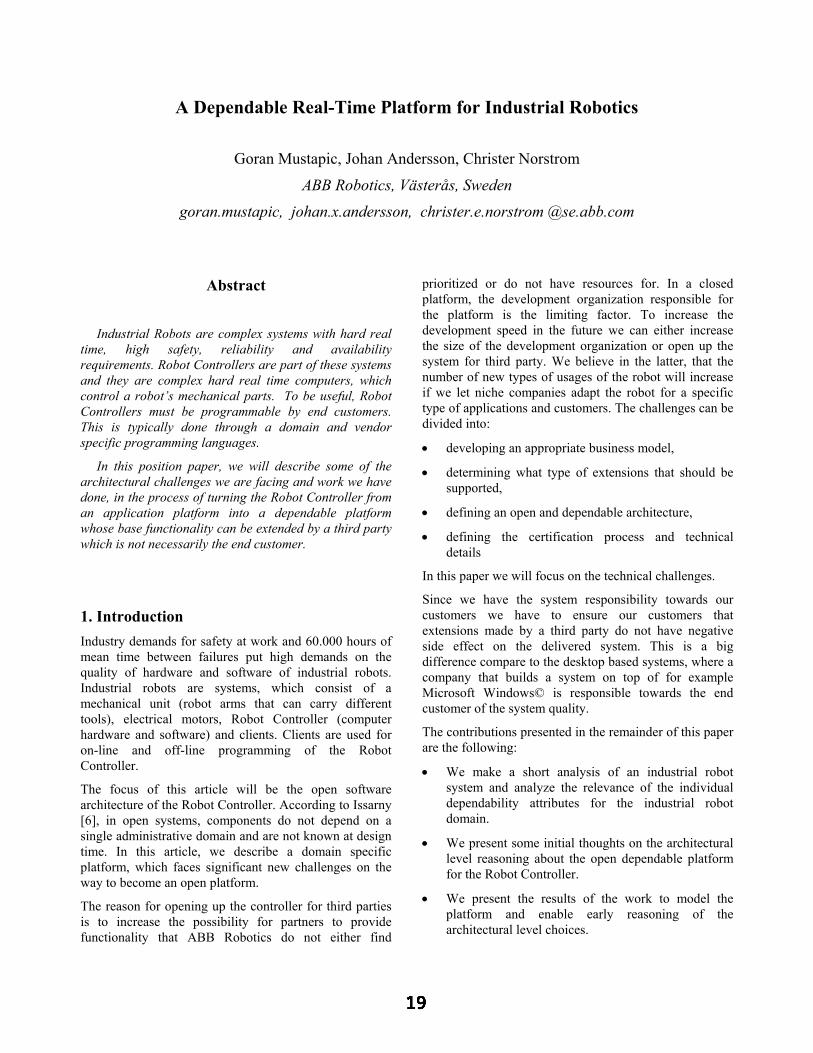
A Dependable Real-Time Platform for Industrial Robotics
Goran Mustapic, Johan Andersson, Christer Norstrom
ABB Robotics, Västerås, Sweden
goran.mustapic, johan.x.andersson, christer.e.norstrom @se.abb.com
Abstract
Industrial Robots are complex systems with hard real time, high safety, reliability and availability requirements. Robot Controllers are part of these systems and they are complex hard real time computers, which control a robot’s mechanical parts. To be useful, Robot Controllers must be programmable by end customers. This is typically done through a domain and vendor specific programming languages.
In this position paper, we will describe some of the architectural challenges we are facing and work we have done, in the process of turning the Robot Controller from an application platform into a dependable platform whose base functionality can be extended by a third party which is not necessarily the end customer.
1. Introduction Industry demands for safety at work and 60.000 hours of mean time between failures put high demands on the quality of hardware and software of industrial robots. Industrial robots are systems, which consist of a mechanical unit (robot arms that can carry different tools), electrical motors, Robot Controller (computer hardware and software) and clients. Clients are used for on-line and off-line programming of the Robot Controller.
The focus of this article will be the open software architecture of the Robot Controller. According to Issarny [6], in open systems, components do not depend on a single administrative domain and are not known at design time. In this article, we describe a domain specific platform, which faces significant new challenges on the way to become an open platform.
The reason for opening up the controller for third parties is to increase the possibility for partners to provide functionality that ABB Robotics do not either find
prioritized or do not have resources for. In a closed platform, the development organization responsible for the platform is the limiting factor. To increase the development speed in the future we can either increase the size of the development organization or open up the system for third party. We believe in the latter, that the number of new types of usages of the robot will increase if we let niche companies adapt the robot for a specific type of applications and customers. The challenges can be divided into:
• developing an appropriate business model,
• determining what type of extensions that should be supported,
• defining an open and dependable architecture,
• defining the certification process and technical details
In this paper we will focus on the technical challenges.
Since we have the system responsibility towards our customers we have to ensure our customers that extensions made by a third party do not have negative side effect on the delivered system. This is a big difference compare to the desktop based systems, where a company that builds a system on top of for example Microsoft Windows© is responsible towards the end customer of the system quality.
The contributions presented in the remainder of this paper are the following:
• We make a short analysis of an industrial robot system and analyze the relevance of the individual dependability attributes for the industrial robot domain.
• We present some initial thoughts on the architectural level reasoning about the open dependable platform for the Robot Controller.
• We present the results of the work to model the platform and enable early reasoning of the architectural level choices.

The outline of the paper is as follows. Section 2 presents a short background about ABB Robot Controller. Section 3 explains the relevance of the individual dependability attributes for our system. In Section 4 we discuss similarities and differences of an open Robot Controller and open desktop systems. Section 5 describes the initial ideas about an open architecture and also the results of an initial case study to model our control system. Finally, in Section 6 we make some conclusions and discuss future work.
2. Background about ABB Robot Controller The ABB Robot Controller was initially designed in the beginning of the 1990. The requirement was that the same controller should be used for all different types of robots, and thus the architecture is a product line architecture. In essence, the controller has an object-oriented architecture and the implementation consists of approximately 2500 KLOC of C language source code divided on 400-500 classes organized in 15 subsystems. The system consists of three computers that are tightly connected: a main computer that basically generates the path to follow, the axis computer, which controls each axis of the robot, and finally the I/O computer, which interacts with external sensors and actuators.
Only one of those three mentioned computer nodes is open to the end users, and that is the main computer. End users write their programming logic in the form of an imperative language called RAPID. This can be done through off-line programming on a PC, or on-line programming on a client called Teach Pendant Unit (custom hardware).
The system was originally designed to support easy porting to new HW-architectures and new operating systems. There were no initial requirements to have an open architecture. Further, the system was not initially designed to support temporal analysis, because of its closed nature and limited amounts of changes that could only be done by the internal development groups.
3. Discussion of dependability attributes in the context of industrial robots The analysis of the dependability attributes in this section is done using the terminology presented by Avizienis, Randell and Laprie in [2]. Dependability is described by the following attributes: Reliability, Availability, Safety, Integrity, Confidentiality, and Maintainability.
Security related attributes (confidentiality and integrity), tend to be of less importance for industrial robots as robots tend to be physically isolated, or only connected to
a control network together with other industrial devices. Integrity of data which is not security related is very important, as it is unacceptable that e.g. one task in the system causes a hazard situation by damaging the safety subsystem. All other dependability attributes are very relevant.
Even though the contact of humans and robots in industrial environments is restricted (robots work in their cells, which are physically isolated by a fence), safety can never be underestimated because a lack of safety can cause substantial physical damages to the robot equipment and its environment. For example, larger types of robots are powerful machines capable of manipulating a weight of 500 kg. Industrial robots belong to the category of safety-critical systems, which do have a safe state.
Because of the nature of the application, it is crucial to have very high availability and reliability. Unreliability leads to un-availability, which means production stop and huge costs. Because of the complex setup of e.g. car production line, a stop of a single robot leads most often to unavailability of a whole production line. In a complex case, a stop of a single robot can cause up to one day production stop.
Maintainability is important in the sense that it is related to availability. The shorter maintenance time the higher is availability of the system. Ideally, the system should be upgradeable without stopping the production. System upgrades are complicated even for a closed platform, but get much more complicated in a platform which is extendable by a third party, because of the compatibility issues.
When it comes to the dependability threats – fault, error and failures, both hardware and software faults need to be considered. Robot Controller software has both roles of sending control sequences to the hardware as well as predicting preventive hardware maintenance.
There are many different fault-tolerance methods that can be applicable for industrial robots. Error recovery with temporary graceful degradation of performance is not acceptable. A robot either works or it does not work; it cannot make its tasks by working slower depending either on the task (such as arc welding) or because it is a link in the production flow.
4. Towards an open architecture In the introduction of this paper, we presented some of the motivations for opening up the system. In this section we will try to describe similarities and differences between industrial robots and open desktop platforms where openness is taken for granted. We will conclude

this section by a short analysis about which dependability attributes are most threatened by opening up the system.
4.1. A comparison to Windows© platform
Good examples of open platforms are Microsoft Windows© and perhaps even more Linux operating systems. We shall take the example of Microsoft Windows©, which is closer to our case. It is possible to extend the base platform on three basic different levels: device driver level, win32 programs and .Net applications. This is illustrated in the Figure 1.
Windows KernelDeviceDriverDevice
DriverDeviceDriver
Win32 API
WindowsApplication
WindowsApplication
WindowsApplication
.Net Framework
.NetApplication
.NetApplication .Net
Application
Figure 1: Different ways to extend Windows© platform
The architecture of the system guarantees that each of the different extensibility mechanism only can make certain amount of harm to the system, where device drivers can do the most harm and .Net application least harm. Apart from the basic or native ways to extend the platform, many of the applications define their own extensibility mechanisms, e.g. Internet Explorer and SQL Server.
The current way of adding functionality to the Robot Controller corresponds to adding .Net applications to Windows©. As previously mentioned, this is by adding RAPID programs. This is shown in the Figure 2.
IOSubsystem
OS Isolation Layer
RAPIDRobot
Application
RAPIDRobot
ApplicationRAPIDRobot
Application
OS Kernel
SafetySubsystem
MotionSubsystem
Program ServerSubsystem
RAPIDextensions
Figure 2: Current ways to extend the Robot Controller software
We are considering the following additional ways of extending the Robot Controller:
• Extensions to the robot programming language RAPID
• New subsystems
• Extension logic to the existing subsystems (e.g. fine-tuning of the robot path, new type of IO card, new types of sensors for fine tuning of the robot path etc.)
Let us consider the first type of extensions – RAPID instructions. Basic commands in programming of a robot are “motion” instructions instructing a robot to move its arms to different positions. Some of the basic motion commands are implemented as RAPID extensions and perform their tasks by communicating to the motion subsystem. The basic part of the Program Server contains the engine for executing RAPID programs, and has features like single stepping and executing the program backwards (that is, running the robot backwards). There is a limited set of commands that make the robot programming language. New instructions can be added to enable easier programming and facilitate e.g. very special kinds of tools that a robot is using. This has traditionally been restricted for in-house development because of the harm these extensions can do to the system and prohibitive costs of verifying the correctness of extensions. This harm is equivalent to the harm that unmanaged (native) code can do to a .Net application. This extension code can bring the .Net application down and .Net Framework has no ways to prevent it from doing this. In the Robot Controller case, situation gets more complicated when timing requirements of the Robot Controller are considered.
Other types of extensions mentioned are potentially even more dangerous to the overall system because they most likely require more open access to the lower level services in the system.
4.2. Revisiting the dependability attributes If we shortly revisit the dependability attributes, which we have analyzed in the section 3, we will see that opening up the architecture will have some significant consequences for several of the attributes. In particular: reliability, availability and safety of the system are threatened by a third party code. Maintainability of the system gets much harder because of the need to handle versioning problems between the platform and the extensions.
Thus we have to find a dependable architecture to support extending the platform in a predictable way.

5. Initial architecture reasoning about open Robot Controller platform We see the following as the most important architectural goals and also biggest challenges we are facing:
• Defining the dependable platform architecture
• Good support for the development of extensions
• Support for the predictable assembly of extensions and the platform
The platform will provide a Software Development Kit (SDK) for developing the platform extensions. SDK functionality may be grouped with focus on different types of extensions. Support for modeling and simulation will be a part of the SDK, as well as a framework for certification of extensions.
Because timing aspects are crucial in the Real-Time environment, we have already done some initial studies on modeling/simulation of the system, to be able to verify the architectural design in early stages. The rest of the work mentioned below is in an initial phase.
5.1. Platform architecture The work on architecture for dependable systems is relevant in the context of defining the architecture of an open dependable platform. According to [3] Non-Functional Requirements (NFR) can be divided to: Separation, Additive (a subset of the Separation) and Integral NFR. The classification is based on the way NFR can be taken into account in the system architecture. Additive non-functional requirements (AFNR) are pure add-on components to the architecture, while integral non-functional requirements (INFR) can affect the components of the entire system.
In the case of an open dependable platform, we will need to use means for dependability to create a framework for adding extensions. The choice of the architecture and implementation of the dependability requirements, will lead to this framework. Means for dependability can be transparent, with a different degree of transparency, to extension developers. We believe that for a hard-real time system, extensions of the platform will have to be aware of the platform dependability requirements. An example is the timing requirements.
Some of the existing frameworks for implementing fault-tolerant software present interesting ideas that we may benefit from. An example is a framework for implementing complex fault-tolerant software presented by Xu, Randel and Romanovsky in [13].
It is also important for the software architecture to support good testability, which is a contradictory requirement to fault-tolerance. Example of the work in
this field that is relevant for us, is the work done by Voas [9,10], and especially some of the work in the area of distributed real time systems [8].
5.2. Research in Component Based Software Engineering (CBSE) The extensions of our platform could also be called components. Component-Based Software Engineering (CBSE) and Software Architecture research are much related [4] and experiences from this field can help us in architecting our platform. It is recognized that current Component Technologies handle only syntactic aspects of component compositions, while semantic and especially extra-functional (non-functional) aspects of component specification are open areas of research [4]. One of the biggest challenges of the CBSE is predictable assembly of components and an example of a technology in this research area is called PECT. We believe our ideas are quite inline with the PECT framework presented by the research group at SEI Carnegie Mellon University in the article “Packaging Predictable Assembly” [5]. In this article, prediction-enabled component technology (PECT) is presented, as both a technology and a method for producing the instances of the technology. A PECT instance is created by integrating a software component technology with one or more analysis models. However, focus of their work seems to be more on integration of the existing technology and models, while our focus will be more towards defining a dependable platform and a simple custom component model with good dependability characteristics.
Besides the predictable assembly, research experiences in CBSE can be very useful for handling problems of maintainability and compatibilities between platform and extensions.
5.3. Certification of extensions
An example of a certification process for platform extensions is Microsoft’s WHQL (Windows Hardware Quality Lab [7]) certification program for the device drivers. Some ideas from this process are definitely applicable to our case. We would also need to act as a certification authority. In our case, the situation is more complicated because it is not only the certification of a single component we are concerned about, but also the already mentioned predictable-assembly. One of the possible approaches to certification of COTS software is presented by Voas in [11].
5.4. Model Checking and Simulation In an open real-time system, with third party components we need a method for extending the base system in a safe way. Since the robot system is very sensitive for timing errors, we have developed a method for analyzing the

impact of adding third party components. In a large system such as the robot controller, this temporal side-effect is hard to predict without models, due to the size and complexity of the system.
Testing and debugging of a complex real-time system is already difficult and when introducing a low-level interface for extending the system with new components makes it even harder. Now, not only the base system has to be verified, but all combinations of extending components that are to be used must be verified as well.
A component might work perfectly, but when it is combined with another component it might introduce an overload situation in some scenarios. This is dangerous since an error caused by this side-effect can be hard to find by testing and affects not only the current task, but may cause a global overload situation, possible delaying several tasks, causing multiple task deadlines to be missed, and finally that the robot fails doing its task properly.
Often the manufacturer of the base system wants to focus on the performance and features of the base system, not integration of special third party components. Letting the component manufacturer be responsible for the extended system is not better and in the industrial robot business, big customers do not accept this. The third party developers will not have access to the source code of the base system, except perhaps an SDK, and will not have the same expertise in the internal structure of the system. Also, they are probably not able to achieve the same quality on their system verification as the base system manufacturer.
A better solution is to let the component developer create a model of their component and let the base system manufacturer certify the component. Their component can through the process be certified for use with the system as well as together with other certified components. This is good for the component developer since it provides a quality label for their software and the base system manufacturer can sell more base systems.
We have developed a method and a prototype tool for describing and analyzing these models. The approach is developed for a robot controller, but the method can be used for other systems as well.
In earlier work, the language-based simulation tool-suite called ART-ML [1,12] was developed, a model creation process has been developed and using it we created a rough model of the controller. A specialized query-language for powerful analysis simulation results as well as data measured on the target system has been developed [12].
So our approach consists of one base step were we develop an initial model of the system and validate that the model represents the modeled system correct. When we have a model of the base system we can add component models to the base model and analyze the consequences of adding a particular set of components. Currently this analysis will be performed off-line but in the future we could do this even on-line.
When creating an initial model M0, of an existing system S0, several distinct activities are required. These activities are depicted in Figure 4. First the structure has to be identified and modeled, i.e. the tasks in the system and synchronization and communication among them. In the next step, we measure the system and populate the structural model with data about the temporal behavior. Moreover, information needed in the validation phase is collected, e.g. response times. When tuning the model, the initial model M0 is compared with S0 by simulating the model and comparing the results with the validation data collected in the previous step. In this step it is possible to introduce more details about the tasks behavior in order to capture the system's behavior accurately.
S0
T0
Structural modeling
U0
V0
M0
Populate the model
Tune the model
Sensitivity analysis
Figure 4: The model creation process
To validate the usefulness of the model it is necessary to perform a sensitivity analysis. The sensitivity analysis should be based on foreseen potential extensions or changes in the particular system. The extensions are introduced in the model as well as in the system and the new systems are compared. Any divergence between the behavior of the simulated model and the system indicates that more details must be introduced in the model. This increases the confidence in the created model.
In the robot controller we have studied, the following typical changes were identified:

• Change existing behavior of a task which results in changes in the execution time distribution.
• Add a task to the system.
• Change the priority of an existing task.
When a third party adds a component to the system a model of the added component has to be provided. This model is composed with all other added components’ models and the basic system model. Based on this composed model, we can verify if the defined properties still hold for that particular combination of components, and if so draw the conclusion that the added components do not affect the system behavior badly.
6. Future Work and Conclusions We intend to continue our work in the direction of defining architecture of a reliable, safe and maintainable platform. We will also continue working on the modeling and simulation to support the predictable assembly of the platform and extension components.
From the initial analysis, which we have presented in this paper, it can be seen that we will need to use experiences from multiple areas of research and to combine them to create an optimal domain specific solution.
Besides the technical challenges, there are also significant business challenges around the certification process. Without proper architecture, tool support etc, costs of certification may turn out to be larger than the benefits of having an open platform.
7. References
[1] Andersson J., Neander J., Timing Analysis of a Robot Controller, Master Thesis, Mälardalen University, Sweden, http://www.mdh.se/, 2002.
[2] Avizienis A., Randell B., and Laprie J.C., "Fundamental Concepts of Computer System Dependability", IARP/IEEE RAS Workshop On Robot Dependability, 2001.
[3] Brandozzi M. and Perry E.D., "Architectural Prescriptions for Dependable Systems", ICSE 2002 Workshop on Architecting Dependable Systems, 2002.
[4] Crnkovic I., Hnich B., Jonsson T., and Kiziltan Z., Specification, Implementation and Deployment of Components, Communications of the ACM, volume 45, issue 10, 2002.
[5] Hissam S., Stafford J., Wallnau K., and Moreno G., "Packaging Predictable Assembly", Proceedings of the First IFIP/ACM Working Conference on Component Deployment, Berlin, Germany, 2002.
[6] Issarny V., "Software Architectures of Dependable Systems: From Closed To Open Systems", ICSE 2002 Workshop on Architecting Dependable Systems, 2002.
[7] Microsoft Corporation, Windows Hardware Quality Lab homepage, http://www.microsoft.com/hwdq/hwtest/, 2003.
[8] Thane H., "Monitoring, Testing and Debugging of Distributed Real-Time Systems", Doctoral Thesis, Royal Institute of Technology, KTH, Mechatronics Laboratory, TRITA-MMK 2000:16, Sweden, 2000
[9] Voas J., "Factors That Affect Software Testability", Pacific Northwest Software Quality Conference, Inc., 1991.
[10] Voas J., Software Assessment - Reliability, Safety, Testability, John Wiley & Sons, Inc, 1995.
[11] Voas J., A Defensive Approach to Certifying COTS Software, report RSTR-002-97-002.01, Reliable Software Technologies Corporation, 1997.
[12] Wall A., Andersson J, and Norstrom C., "Probabilistic Simulation-based Analysis of Complex Real-Time Systems", will appear in the 6th IEEE International Symposium on Object-Oriented Real-time Distributed Computing, Hakodate Hoikado, Japan, 2003.
[13] Xu J., Randell B., and Romanovsky A., "A Generic Approach to Structuring and Implementing Complex Fault-Tolerant Software", nr 5th ISORC'02, IEEE Computer Society, 2002.

A Framework for Using Component Redundancy for self-Optimising and self-Healing Component Based Systems
Ada Diaconescu*, John Murphy*
Performance Engineering Laboratory, Dublin City University {diacones,murphyj}@eeng.dcu.ie
* The authors’ work is funded by Enterprise Ireland Informatics Research Initiative 2001
Abstract
The ever-increasing complexity of software systems makes it progressively more difficult to provide dependability guarantees for such systems, especially when they are deployed in unpredictably changing environments. The Component Based Software Development initiative addresses many of the complexity related difficulties, but consequently introduces new challenges. These are related to the lack of component intrinsic information that system integrators face at system integration time, as well as the lack of information on the component running-context that component providers face at component development time.
We propose an addition to existing component models, for enabling new capabilities such as adaptability, performance optimisation and tolerance to context-driven faults. The concept of ‘component redundancy’ is at the core of our approach, implying alternate utilisation of functionally equivalent component implementations, for meeting application-specific dependability goals.
A framework for implementing component redundancy in component-based applications is described and an example scenario showing the utility of our work is given.
1. Introduction
Extensive employment of software systems in various domains raised the concern for the dependability guarantees provided by such systems (e.g. performance, reliability, robustness). Nevertheless, the ever-increasing size and complexity of modern software systems leads to more complicated and expensive system design, testing and management processes, decreasing system flexibility and making it difficult to control dependability characteristics of such systems [1].
In this context, Component Based Software Development (CBSD) has emerged as a new solution that promises to increase the reliability, maintainability and overall quality of large-scale, complex software applications. In the CBSD approach, software applications are developed by assembling made or bought (i.e.
commercial off-the-shelf - COTS) components, according to a well-defined software architecture.
Consequently, the dependability of component-based software applications is determined by both the dependability of the individual components involved, as well as by the adopted software architecture. Considerable research efforts towards determining optimal software architectures ([2], [3], [4]) with respect to the system quality attributes [5], as well as towards achieving dependability guarantees for COTS components ([6], [7]), support this idea. The impact software architecture has on the overall software system performance is also demonstrated in [8]. In this paper, it is shown how different software architectures, providing the same functionalities, yielded different performance results while running in identical environmental conditions.
Information on the context in which a software component or application will run (e.g. hardware and software resources, workloads and usage patterns) is vital when taking architectural, or design decisions. At software development or integration time though, it is impossible to predict with sufficient accuracy, the environmental conditions in which software components or applications will be deployed. In addition, the initial deployment conditions can dynamically change at runtime. Using COTS components exacerbates the problem, by increasing the level of indetermination and making it hard to provide dependability guarantees for the running system [6], [7].
Assuming that different architectural, design and implementation-related choices proved optimal in different environmental circumstances, we argue that it would be beneficial for system quality if the software application could accordingly adapt at runtime, when accurate information were available. We propose the use of redundancy in order to enable such capabilities for component-based software systems. Our intent is to enhance one of the existing component platforms (e.g. EJB, .NET, or CCM) with support for software component redundancy. The predicted benefits of this approach include constant, automatic performance optimisation for running applications, as well as tolerance to certain categories of non-functional, integration-specific faults (e.g. deadlocks, data corruption). By non-

functional faults, we mean faults that are not related to an application’s expected functionality and therefore do not imply any application-specific behavioural knowledge or extra implementation effort to detect.
The rest of the paper is structured as follows. Section 2 provides an overview of our research proposal. An example scenario, indicating the benefit of our work, is presented in Sections 3. A general architecture for our proposed framework is described in Section 4. Section 5 places our approach in the context of similar work in the area. We conclude and present future work in Section 6.
2. Research overview
Our research goal is to enable dynamic adaptability capabilities in complex, component-based software systems, running in unpredictably changing environments, in order to automatically optimise and maintain their dependability characteristics.
Central to our solution is the concept of (software) component redundancy. By this concept, we mean that a number of component implementation variants, providing the same or similar services, are available at runtime. We refer to these component variants as redundant components and say that a set of redundant components providing an equivalent service constitutes a redundancy group (with respect to that service). Any component variant in a certain redundancy group can be functionally replaced with any other component variant in the same redundancy group.
Only one of the redundant components providing a service is assigned, at any moment in time, for handling a certain client request for that service (i.e. an instance of that component is forwarded the client request). This differs from other approaches (e.g. N-version programming; agent-based systems [9]), where a number of the available redundant variants work in parallel, towards a common result. We refer to a component variant that the application is currently using (i.e. sending client requests to instances of that component version) as an active component variant. Component variants that are not currently considered for handling client requests are referred to as passive component variants.
If instances of an active component variant fail, or perform poorly in a certain context, the component variant can be deactivated and replaced with an alternative member of the same redundancy group. This is the main means by which redundancy groups continually optimise themselves, while dealing with changing execution contexts, or context-driven faults.
We do not constrain the component redundancy concept to the level of atomic components [10] [Figure 1-a]. This concept can also be applied to composite components [Figure 1-b] (i.e. composites [10],
‘containing’ a number of sub-components) or to component sets, or groups (i.e. components ‘using’ other components) [Figure 1 – c]. Therefore, through the rest of the paper, references to redundant components can imply atomic, composite, or sets of components.
Figure 1: Redundancy granularities
We intend to implement all functionalities that are required to support and benefit from component redundancy at the component platform level. No development effort overhead is to be placed on the developers of software components that are to be deployed and run on such platforms. Of course, in order for redundancy to be enabled, alternative variants would have to be provided. However, our approach does not require that multiple redundant components be available at software application deployment or runtime. The only constraint is that at least one component version must be available for each external interface, at all times. While complying with this constraint, redundant components can be dynamically added or removed from the software system, at runtime.
We propose that a formal component description be available for every deployed component variant. The description includes information on both functional (e.g. provided and required services) and non-functional (e.g. quality attributes, recommended resources) characteristics of the component (e.g. similar to contracts as in [10], or [11]). Most system quality characteristics depend upon the execution context (e.g. response time is influenced by workload and available resources). These variations are represented in component descriptions as a list of [environment related parameters, corresponding values] pairs. Initially, component non-functional characteristics can optionally be provided by component developers, based on estimations, test results, or previous experience with the supplied components. While a component variant is active, its initial quality description is updated with run-time monitoring information, for the precise application configuration and execution environment.
3. Example
In this section, we provide an example of a possible scenario in which our approach proves to be beneficial. For this example, we opted for the EJB component

technology. However, we believe our framework is generic enough to be applied to other component models.
The example involves two different component implementations providing the same functionality: repeatedly retrieving information from a remote database. The two components differ at the design level. The first design variant involves a single Session Bean, containing SQL code for directly accessing the database. We will refer to this variant as the Direct DB variant. In the second design variant, a Session Bean uses an Entity Bean as means of interacting with the database. We will refer to this variant as the Using Entity Bean variant. A client Session Bean is used for calling these two variants, repeatedly requesting information.
We deployed our EJB example on an IBM WebSphere application server, on Windows2000, running on an Intel Pentium4, with 1.6GHz CPU and 512 MB RAM. We used a DB2 database, running on Windows2000, Intel Pentium 4, 1.6 GHz CPU and 256 MB RAM. A third machine was used for generating traffic and loading the network link to the remote database, to various degrees. We used the Tfgen traffic generator for this purpose. The three machines were connected through a switched 100 Mbps Ethernet LAN, completely separated from other traffic.
We measured the response delays for each version, in different environmental conditions (i.e. available bandwidth on the network links) and usage patterns (i.e. number of repetitive read requests per client transaction).
When the network is lightly loaded, we experience smaller delays in the Direct DB variant than in the Using Entity Bean variant, regardless of the number of repetitive client requests (e.g. 1, 10, 100, 1000 [requests per transaction]). This can be accounted for by the overhead incurred (in the Using Entity Bean variant) by the extra inter-process communication and Entity EJB management.
However, increasing the load on the network link to the remote database has significant impact on the Direct DB approach, while hardly affecting the Using Entity Bean. This can be explained by the fact that the Direct DB variant needs to access the database for each individual (client) read request. The Using Entity Bean variant, involves a single database access per client transaction (i.e. only for the first read request in the transaction), as the data is then locally stored at the Entity Bean instance level and retrieved from there for subsequent requests. Therefore, for increased network loads (e.g. 90% load) and number of read requests, the Direct DB design choice produces higher delays than the Using Entity Bean does. Using an Entity Bean to read from the database becomes, in these circumstances, the optimal choice.
The optimal variant switching point between the two implementations is reached when the inter-process communication and CPU overhead (i.e. in the Using Entity Bean variant) is exceeded by the repeated remote
database access overhead (i.e. in the Direct DB variant). Figure 2 shows the response-time curves corresponding to the two redundant variants, for various network loads, when 1000 read requests were made per client transaction. For obtaining these curves, we repeatedly measured the response delays of such repetitive client requests, for different network loads. We then calculated the average delay value, for each network load.
Figure 2: response-time curves
Even though simple, this example shows how alternating the activation of two redundant variants can ensure better performance than either variant could, at all times. We argue that it is hard, if not impossible to devise a component version that exhibits optimal characteristics in all possible running contexts. The optimal component variant depends on the component execution environment, which can frequently change. Our focus is on the adaptation logic for automatically determining optimal component variants and optimal combinations of component variants, in different running contexts.
4. Framework general architecture
We propose implementing component redundancy as a new service provided by component platforms (i.e. besides already provided services, such as security, transaction support, or life-cycle management). Three main functionalities were identified as needed for the support, utilization and management of redundant components and were associated with three logical tiers in our framework [Figure 3]: i) Monitoring tier; ii) Evaluation tier and iii) Action tier. In this section, we present the main roles and functionalities of each of these tiers and discuss the way they interact in order to provide the component redundancy service.
The Monitoring tier is concerned with acquiring run-time information on the software application as well as on its execution environment. Run-time monitoring implies that information is collected exclusively for the active component variants. It is also the responsibility of the Monitoring tier to analyse the collected information and identify any potential ‘problem’ components [1], [12].
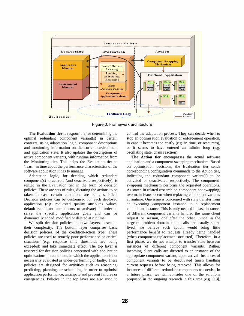
The Evaluation tier is responsible for determining the optimal redundant component variant(s) in certain contexts, using adaptation logic, component descriptions and monitoring information on the current environment and application state. It also updates the descriptions of active component variants, with runtime information from the Monitoring tier. This helps the Evaluation tier to ‘learn’ in time about the performance characteristics of the software application it has to manage.
Adaptation logic, for deciding which redundant component(s) to activate (and deactivate respectively), is reified in the Evaluation tier in the form of decision policies. These are sets of rules, dictating the actions to be taken in case certain conditions are being satisfied. Decision policies can be customised for each deployed application (e.g. requested quality attributes values, default redundant components to activate) in order to serve the specific application goals and can be dynamically added, modified or deleted at runtime.
We split decision policies into two layers, based on their complexity. The bottom layer comprises basic decision policies, of the condition-action type. These policies are used to remedy poor performance or critical situations (e.g. response time thresholds are being exceeded) and take immediate effect. The top layer is reserved for decision policies concerned with application optimisations, in conditions in which the application is not necessarily evaluated as under-performing or faulty. These policies are designed for activities such as reasoning, predicting, planning, or scheduling, in order to optimise application performance, anticipate and prevent failures or emergencies. Policies in the top layer are also used to
control the adaptation process. They can decide when to stop an optimisation evaluation or enforcement operation, in case it becomes too costly (e.g. in time, or resources), or it seems to have entered an infinite loop (e.g. oscillating state, chain reaction).
The Action tier encompasses the actual software application and a component-swapping mechanism. Based on optimisation decisions, the Evaluation tier sends corresponding configuration commands to the Action tier, indicating the redundant component variant(s) to be activated or deactivated respectively. The component-swapping mechanism performs the requested operations. As stated in related research on component hot swapping, two main issues occur when replacing component variants at runtime. One issue is concerned with state transfer from an executing component instance to a replacement component instance. This is only needed in case instances of different component variants handled the same client request or session, one after the other. Since in the targeted problem domain client calls are usually short-lived, we believe such action would bring little performance benefit to requests already being handled (when component replacement occurred). Therefore, in a first phase, we do not attempt to transfer state between instances of different component variants. Rather, incoming client calls are directed to an instance of the appropriate component variant, upon arrival. Instances of component variants to be deactivated finish handling current requests before being removed. This allows for instances of different redundant components to coexist. In a future phase, we will consider one of the solutions proposed in the ongoing research in this area (e.g. [13],
Figure 3: Framework architecture

[14]). The other issue is maintaining client references consistency. We adopt a proxy-based solution to address this issue. Component technologies based on contextual composition frameworks [10] provide a straightforward way of implementing this. That is because clients can only call component instances through the component container, in which the component was deployed and run. The component container can consequently be modified so that to transparently (re)direct client requests to instances of active component variants. In brief, in a first phase of our research, we adopt a client request indirection strategy for implementing the component hot-swapping mechanism.
In our framework, the three presented tiers operate in an automated, feedback-loop manner [Figure 3]: the application performance is monitored and evaluated, the optimal redundant component(s) are identified and activated and the resulting application is monitored and (re-)evaluated. Decision policies at both layers can be dynamically tuned in effect. It is important to note that as these are logical tiers, the boundaries between them may not be as clearly marked when implemented.
4.1. Hierarchical adaptation mechanism
When considering large-scale component-based applications, global optimisations may not always be desirable. Evaluating an overall application, potentially consisting of hundreds of components, whenever an individual component or a group of components does not behave as expected, might induce unnecessary overhead and not scale well. We propose distributing the adaptation mechanism. That is, if a problem is detected at an individual component level, the problem is dealt with locally, by means of redundant component replacement. Nevertheless, exclusively concentrating on local optimisations might not globally optimise the system. Therefore, our framework employs (three-tiered) adaptation mechanisms with different scopes (e.g. local, group, global), organised in a hierarchal manner. Detected problems can be dealt with locally or/and signalled upwards the hierarchical tree, up to the global level. Adaptation mechanisms can be dynamically activated or deactivated, in order to reduce overhead, when possible. This idea is also presented in [12], in the context of non-intrusive, EJB system monitoring.
5. Related Work
Redundancy for increased robustness or reliability has been successfully used in various domains (e.g. hardware, mechanics, or constructions). The same concept was introduced in the software domain (e.g. [9], or as ‘design
diversity’ in [6], [15]), in order to achieve fault-tolerance capabilities for software systems. A few examples of fault tolerant schemes implementing this concept are N-version programming, N self-checking software, recovery blocks [16], or exception handling approaches. However, as these schemes target system fault tolerance, they imply both the presence of knowledge of the correct system behaviour, as well as of methods for assessing system behaviour at runtime, in order to detect faults. We target a different problem domain, encompassing performance-related problems and non-functional faults, which can generally be detected without needing application semantics information. Our framework can consequently be implemented as part of the component platform layer, for the benefit of all applications deployed on such platforms.
Similar to our performance optimisation related intent, the Open Implementation initiative [17] allows clients to decide which implementation variant to use (i.e. instantiate) for optimal performance, in a specific context. We propose that the component platform automatically take such decisions. In our view, it is very expensive, or even impossible for a system manager to optimally perform such activities in due time, in the case of complex systems or frequent environmental changes.
Redundancy as a means of achieving dependability for Internet systems (i.e. Web Services based) is proposed in the RAIC [13] project. The addressed problem domain in this case however, is different in scope from our work. This is because such systems rely on Internet services offered by different providers, from different locations. No single authority owns, or has complete control over the entire system. The Internet system developer has no knowledge of, or access to the implementation, deployment platform, or supporting resources of the services it needs to use. Redundancy support cannot be implemented in this case at the component deployment platform level. Instead, redundancy support for the services that Internet systems use is implemented at the software application level of such systems.
Research in the area of dynamic component versioning presents certain similarities to our work. However, the main intent of the two research directions is different, emphasising different aspects. Component versioning is concerned with verifying whether new versions are better than old ones, before dynamically upgrading the system. In [14] for example, the best component version is determined by means of online testing. Even though the possibility of multiple versions being kept is considered, the way such versions are to be used is not elaborated.
A significant research area, closely related to our work, is concerned with specifying and building dynamic adaptability capabilities for self-repairing systems. Mostly related to our work are approaches based system architectural models [18], [19]. A feedback-loop
mechanism (separated from system business logic) is employed for adapting running systems to changing requirements, or environmental conditions. This mechanism is designed in a centralised manner. Monitoring information is centralised, evaluated using analytical methods (e.g. queuing theory) and the system is globally optimised. Our approach adopts a hierarchical adaptation approach, where global system optimisation can generally be avoided. We focus on adaptation operations related to redundant component replacements.
An important aspect of our research is the fact that we exclusively target component-based applications based on contextual composition frameworks [10]. The unique nature of such applications (e.g. soft inter-component bindings; unpredictable number of component instances) might make approaches devised for component-based systems in general (i.e. in which ‘components’ can mean clients, servers, or software modules), difficult to apply.
6. Conclusions and Future Work
This paper proposed the use of component redundancy for enabling self-optimisation, self-healing and dynamic adaptation capabilities in component-based software systems. A component redundancy related terminology was defined. We argued that system complexity, lack of sufficient information and changing execution conditions make it impossible to create and ascertain components that exhibit optimal dependability characteristics at all times. An example was presented to support this idea. In this example, different strategies were selected for implementing two distinct component variants providing the same functionality. Each implementation variant proved optimal (with respect to response delays) in different environmental conditions. As these results indicate, knowledgeably alternating the usage of redundant components, optimised for different running contexts, ensures better overall performance than either component variant could provide.
A framework for implementing the component redundancy concept was described. We identified the main roles and functionalities this framework needs to provide and categorised them into three logical tiers: monitoring, evaluation and action. We proposed distributing the three logical tiers, organising them (each) in a hierarchical manner, in order to reduce overhead.
As future work, we intend to provide a proof-of-concept implementation of our framework and test it against our example scenario. In addition, further scenarios and case studies will be identified and documented. The cost of acquiring multiple redundant components, as well as the impact of using redundant components on the overall application performance and resource usage will have to be analysed.
7. References
[1] J. O. Kephart, D. M. Chess, “The Vision of Autonomic Computing”, IEEE Computer, January 2003 [2] C. U. Smith, L. G. Williams, “Software Performance Engineering: A Case Study with Design Comparisons”, IEEE Trans. Software Eng., Vol. 19, No 7, July 1993 [3] F. Aquilani, S. Balsamo, P. Inverardi, “Performance Analysis at the Software Architectural Design Level”, Performance Evaluation, Volume 45, Number 2-3, July 2001 [4] J. Bosch, P. Molin, “Software Architecture Design: Evaluation and Transformation”, IEEE Conference and Workshop on Engineering of Computer-Based Systems, Nashville, Tennessee, March 1999 [5] M. Klein et al., “Attribute-Based Architecture Styles”, in Proceedings of the First Working IFIP Conference on Software Architecture (WICSA1), San Antonio, TX, 1999, pp 225-243 [6] P. Popov, L. Strigini, A. Romanovsky, “Diversity for Off-The-Shelf Components”, International Conference on Dependable Systems&Networks, NY, USA, 2000, pp. B60-B61 [7] P. A. C. Guerra, C. M. F. Rubira, R. de Lemos, “An Idealized Fault-Tolerant Architectural Component”, Workshop on Architecting Dependable Systems, Orlando, FL, May 2002 [8] E. Cecchet et al., “Performance and Scalability of EJB Applications”, Proc of 17th ACM Conference on Object-Oriented Programming, Seattle, Washington, 2002, pp 246-261 [9] M.N. Huhns, V.T. Holderfield, "Robust Software", Agents on the Web, IEEE Internet Computing, March/April 2002 [10] C. Szyperski, with D. Gruntz and S. Murer, “Component Software: Beyond Object-Oriented Programming”, Second Edition, Addison-Wesley Pub Co, 1 November 2002 [11] B. Meyer, C. Mingins, H. Schmidt: Trusted Components for the Software Industry. IEEE Computer 5/1998, pp. 104-105 [12] A. Mos, J. Murphy, “Performance Management in Component-Oriented Systems using a Model Driven Architecture Approach”, The 6th IEEE International Enterprise Distributed Object Computing Conference (EDOC), Lausanne, Switzerland, September 2002 [13] C. Liu, D. J. Richardson, “RAIC: Architecting Dependable Systems through Redundancy and Just-In-Time Testing”, ICSE, Workshop on Architecting Dependable Systems (WADS), Orlando, Florida, 2002 [14] M. Rakic, N. Medvidovic, “Increasing the Confidence in Off-the-Shelf Components: A Software Connector-Based Approach”, Symposium on Software Reusability: putting software reuse in context, Toronto, Ontario, Canada, 2001 [15] B. Littlewood et al., “Modeling software design diversity: a review”, ACM Press, New York NY, USA, 2001, pp 177-208 [16] B.Randell and J.Xu, “The Evolution of the Recovery Block Concept”, Software Fault Tolerance, JohnWiley&SonsLtd, 1995 [17] G. Kiczales, “Beyond the Black Box: Open Implementation”, IEEE Software, January 1996 [18] S. Cheng et al., “Using Architectural Style as a Basis for Self-repair”, Proc. Working IEEE/IFIP Conference on Software Architecture, Montreal, August, 2002 [19] P. Oriezy et al., “An Architecture-Based Approach to Self-Adaptive Software”, IEEE Intelligent Systems, May/June 1999, p. 54-62

Elements of the Self-Healing System Problem Space
Abstract
One of the potential approaches to achievingdependable system operation is to incorporate so-called“self-healing” mechanisms into system architectures andimplementations. A previous workshop on this topicexposed a wide diversity of researcher perspectives onwhat self-healing systems really are. This paper proposes ataxonomy for describing the problem space for self-healingsystems including fault models, system responses, systemcompleteness, and design context. It is hoped that thistaxonomy will help researchers understand what aspects ofthe system dependability problem they are (and aren’t)addressing with specific research projects.
1. Introduction
Self-healing systems form an area of research that is in-
tuitively appealing and garnering increased attention, but
not very well defined in terms of scope. At the 2002 Work-
shop on Self-Healing Systems [WOSS02], it became clear
that researchers have differing views on what comprises re-
search on self-healing systems. This paper attempts to doc-
ument those views in the form of a description of the
self-healing systems research problem space.
There is a rich set of existing knowledge on the general
topic of dependable systems, and on techniques that can
reasonably be considered to comprise “self-healing.” For
example, one view of self-healing systems is that they per-
form a reconfiguration step to heal a system having suffered
a permanent fault. The use of standby spares in such a man-
ner has been called “self-repair” [Bouricius69]. Systems
that use modular redundancy (e.g., [vonNeuman56]) can
tolerate component failures and might be considered to be
self-healing.
It is premature to propose a consensus-based definition
of the term “self-healing,” so we do not attempt to do this
beyond an appeal to intuition that such a system must some-
how be able to “heal” itself. Whether this means that
self-healing systems are really a subset of traditional
fault-tolerant computing systems is unclear. However, the
topic of self-healing systems has attracted a number of re-
searchers who would not otherwise have been involved in
the fault tolerant computing area. So, if nothing else, the la-
bel of self-healing has broadened the pool of researchers
addressing the difficult problems of creating dependable
systems.
To give researchers in this area a common basis for de-
fining the scope of self-healing systems research, it seems
worthwhile to set forth a description of issues being ad-
dressed by various research projects. This might provide a
way for researchers to realize they mean considerably dif-
ferent things by their use of the phrase “self-healing,” as
well as to understand the similarities and differences in
their approaches and domains. Toward that end, this paper
attempts to describe the general problem space relevant to
self-healing system research.
2. Elements of the model
Based on our experiences and observations at the
WOSS02 workshop, we propose that there are four general
categories of aspects to the self-healing system problem
space: fault model, system response, system completeness,
and design context (Table 1). (The particular categories
are not important, but simply form a way to group related
concepts for the purposes of discussion.) We shall discuss
the elements of each category in turn.
[Avizienis01] contains an extensive taxonomy of fault
tolerant computing terminology and approaches. We use
this as the basis for terminology, and as the basis for the
fault modeling portion of the taxonomy.
2.1. Fault model
Self-healing systems have similar goals to the general
area of dependable computer systems. (Not all dependable
computing research areas are “self-healing”, but one can ar-
gue that all “self-healing” techniques ultimately are de-
pendable computing techniques.)
One of the fundamental tenets of dependable computing
is that a fault hypothesis (often called a fault model) must
be specified for any fault tolerant system. The fault hypoth-
Philip KoopmanInstitute for Software Research, International
& ECE DepartmentCarnegie Mellon University
Pittsburgh, PA, [email protected]

esis answers the question of what faults the system is to tol-
erate. (If one doesn’t know what types of faults are to be
tolerated, it is difficult to evaluate whether a given system is
actually “fault tolerant.”)
In a similar vein, self-healing systems must have a fault
model in terms of what injuries (faults) they are expected to
be able to self-heal. Without a fault model, there is no way
to assess whether a system actually can heal itself in situa-
tions of interest. The following are typical fault model
characteristics that seem relevant.
Fault duration: Faults can be permanent, intermittent
(a fault that appears only occasionally), or transient (due to
an environmental condition that appears only occasion-
ally). Since it is widely believed that transient and intermit-
tent faults outnumber permanent faults, it is important to
state the fault duration assumption of a self-healing ap-
proach to understand what situations it addresses.
Fault manifestation: Intuitively, not all faults are as se-
vere as others. Beyond that, components themselves can be
designed to exhibit specific characteristics when they en-
counter faults that can make system-level self-healing sim-
pler. A common approach is to design components that are
fail-fast, fail-silent. However, other systems must tolerate
Byzantine faults which are considered “arbitrary” faults.
(It is worth noting that Byzantine faults exclude systematic
software defects that occur in all nodes of a system, so the
meaning of “arbitrary” is only with respect to an assump-
tion of fault independence.)
Beyond the severity of the fault manifestation, there is
the severity of how it affects the system in the absence of a
self-healing response. Some faults cause immediate sys-
tem crashes. But many faults cause less catastrophic conse-
quences, such as system slow-down due to excessive CPU
loads, thrashing due to memory hierarchy overloads, re-
source leakage, file system overflow, and so on.
Fault source: Assumptions about the source of faults
can affect self-healing strategies. For example, faults can
occur due to implementation defects, requirements defects,
operational mistakes, and so on. Changes in operating en-
vironment can cause a previously working system to stop
working, as can the onset of a malicious attack. While soft-
ware is essentially deterministic, there are situations in
which it can be argued that a random or “wear-out” model
for failures is useful, suggesting techniques such as
periodic rebooting as a self-healing mechanism. Finally,
some self-healing software is designed only to withstand
hardware failures such as loss of memory or CPU capacity,
and not software failures.
Granularity: The granularity of a failure is the size of
the component that is compromised by that fault. (The re-
lated notion of the size of a fault containment region is a key
design parameter in fault tolerant computers.) A fault can
cause the failure of a software module (causing an excep-
tion), a task, an entire CPU’s computational set, or an entire
computing site. Different self-healing mechanisms are
probably appropriate depending on the granularity of the
failures and hence the granularity of recovery actions.
Fault profile expectations: Beyond the source of the
fault is the profile of fault occurrences that is expected.
Faults considered for self-healing might be only expected
faults (such as defined exceptions or historically observed
faults), faults considered likely based on design analysis, or
faults that are unexpected. Additionally, faults might be
random and independent, might be correlated in space or
time, or might even be intentional due to malicious intent.
2.2. System response
The first step in responding to a fault is, in most cases,
actually detecting the fault. Beyond that there are various
ways to degrade system operation as well as attempt recov-
ery from or compensation for a fault. Each application do-
main has extra-functional aspects that are important, such
as reliability, safety, or security. These extra-functional
concerns influence desired system responses.
Fault Detection: Fault detection can be performed in-
ternally by a component, by comparing replicated compo-
nents, by peer-to-peer checking, and by supervisory
checks. Additionally, the intrusiveness of fault detection
can vary from nonintrusive testing of results, to execution
of audit or check tasks, redundant execution of tasks,
Fault model:Fault durationFault manifestationFault sourceGranularityFault profile expectations
System response:Fault DetectionDegradationFault responseFault recoveryTime constantsAssurance
System completeness:Architectural completenessDesigner knowledgeSystem self-knowledgeSystem evolution
Design context:Abstraction levelComponent homogeneityBehavioral predeterminationUser involvement in healingSystem linearitySystem scope
Table 1. Problem space model elements.

on-line self-test, and even periodic reboots for the purpose
of more thorough self tests. Systems might inject faults in-
tentionally as on-line tests of fault detection mechanisms.
A related area is that of ensuring that all aspects of a system
are activated periodically so that any latent accumulated
faults can be detected within a bounded time. Not all sys-
tems can achieve 100% fault detection in bounded time.
Degradation: Self-healing systems might not restore
complete functionality after a fault. The degree of de-
graded operation provided by a self-healing system is its re-
silience to damage that exceeds built-in redundancy. Some
systems must fail entirely operational (i.e., cannot fulfill
their mission without full functionality). But many systems
can degrade performance, shed some tasks, or perform
failover to less computationally expensive degraded mode
algorithms.
Fault Response: Once a fault has been detected, the
system must select a response mechanism. Typical on-line
responses include masking a fault (e.g., modular redun-
dancy that performs a majority vote of independent compu-
tational results), rollback to a checkpoint, rollforward with
compensation, or retrying an operation using the original or
alternate resources. Heavier-weight responses include sys-
tem architectural reconfiguration (on-the-fly or involving a
reboot), invoking alternate versions of tasks, killing less
important tasks, and requesting assistance from outside the
system. The fault response might be optimized to maintain
desired properties such as correctness, quality of service
contracts, transactional integrity, or safety. Fault responses
might also be preventative (such as a periodic system re-
boot), proactive (such as an action triggered by a burst of
faults which were tolerated but are indicative of a possible
near-term failure), or reactive.
Recovery: After a system has detected a fault, poten-
tially degraded, and invoked a fault response, it must re-
cover operation to complete the self-healing process.
Recovery involves issues such as integrating newly com-
mitted resources into ongoing processes, “warming up” re-
sources by transferring system state into them, or taking
action to bring the system to a clean known state before pro-
ceeding with operations. A component might be
hot-swapped, require a warm system reboot, or require a
cold system reboot to finish recovery.
Time constants: The time constants of a system, along
with the fault distribution assumptions, play a large role in
determining what types of self-healing are feasible. The
time constant of faults with respect to the forward progress
of computations determines things like the frequency at
which checkpoints must be taken, or whether a system can
reboot itself quickly enough to prevent an overall system
outage. Additionally, if intermittent or transient faults are
in the majority as is typical in many systems, the speed of
the detection-response-recovery cycle might need to be
faster than typical fault arrival periods to avoid system
thrashing.
Assurance: Every domain has a specific set of system
properties of importance. Every system requires assur-
ances of some level of functional and extra-functional cor-
rectness for normal operation. Self-healing systems
additionally require a way to assure that such properties are
maintained during and after fault occurrences. Challenges
in this area include assurance between the time a fault oc-
curs and the time the fault is detected (keeping in mind that
not all faults are detected); assurance during degraded
mode operations; and assurance during recovery opera-
tions. This assurance might be provided at design time or
might involve checks at run time. Finally, the assurance
might be absolute or probabilistic, and might involve all
functionality or partial assurance of only a few key system
properties.
2.3. System completeness
Real systems are seldom complete in every sense.
Self-healing approaches must be able to deal with the real-
ity of limits to knowledge, incomplete specifications, and
incomplete designs.
Architectural completeness: Few system architectures
are completely elaborated when the first implementation is
built. Architectures and implementations evolve over time.
Many systems are “open” in that third-party components
can be added during or after system deployment. And,
many systems are designed using prebuilt components that
have details and behavior so opaque to the overall system
designer that the architecture might as well be considered
incomplete. Finally, a system might be built upon discov-
ery mechanisms which are intended to extend the architec-
ture or implementation at run-time. A related issue is that
implementations of components evolve, are patched, suffer
configuration management problems, and so on.
Designer knowledge: Designers in the typical case do
not have complete knowledge of the systems they design.
Any system is designed using a set of abstractions about un-
derlying components. But beyond that the designer must
deal with missing knowledge about aspects of components,
and in all likelihood incorrect knowledge about system
components due to documentation and implementation de-
fects. It is common for designers to have a thorough under-
standing of typical system behaviors, but to have little or no
understanding of atypical system behaviors – especially
system behaviors in the presence of faults. A vital aspect of
designer knowledge is how well the fault model for the sys-
tem is characterized and whether field information about
faults is fed back to the system designer.
System self-knowledge: Systems must have some level
of knowledge about themselves and their environment in

order to provide self-healing. This self-knowledge is lim-
ited by the aspects of knowledge built into a component (for
example, a component might or might not be able to predict
its execution time in advance), the accessibility of knowl-
edge about one component to another component, and de-
fects in representation of such knowledge either due to
initial design defects or staleness caused by system evolu-
tion. The concept of reflection is often discussed in the
context of system self-knowledge; however it also seems
possible to build systems that have no awareness of their
state but rather exhibit emergent correctness as a conse-
quence of the interaction of their component behaviors.
System evolution: Self-healing systems must deal with
the fact that they change over time. Sources of change in-
clude designed operating mode changes, accumulated com-
ponent and resource faults, adaptations to external
environments, component evolution, and changes in sys-
tem usage. Making use of available information on system
dynamics might help with self-healing, such as being able
to count on a scheduled system outage (or self-schedule an
outage) to perform healing.
2.4. Design context
There are several other factors that influence the scope
of self-healing capabilities that could be considered to form
the design context of the system.
Abstraction level: Systems can attempt to perform vari-
ous forms of self-healing to application software,
middleware mechanisms, operating systems, or hardware.
Self-healing techniques can be applied to implementations
(such as wrappers to deal with unhandled exceptions) or ar-
chitectural components.
Component homogeneity: While some systems have
completely homogenous components, it is common to have
systems that are heterogeneous to some degree. Server
farms often have different versions of processing hardware,
and might well have different versions of operating systems
or other software installed, especially when changes are ap-
plied incrementally across a fleet of components as a risk
management technique. Homogeneity can consist of exact
component duplicates, or components that are “plug-com-
patible” even though they have differing implementations.
Some systems are inherently heterogenous, such as the
computational components within embedded systems such
as automobiles. The heterogeneity of a system tends to
limit its ability to simply migrate computational tasks as a
self-healing strategy and requires that self-healing ap-
proaches deal with the issue of configuration management
of systems both before and after healing.
Behavioral predetermination: Most systems do not
have perfectly predetermined and deterministic behavior,
and some self-healing approaches must be able to accom-
modate this. Non-deterministic behavior abounds in hard-
ware and in software infrastructure. But, beyond that, it is
often impractical to quantify things such as absolute
worst-case execution time. Even things that might seem
determinable in theory such as enumeration of all possible
exceptions that can be generated by a software component
might be impractical due to obscure component interac-
tions or defects. In the time dimension, system tasks might
be event-based or periodic, necessitating differing assump-
tions and approaches by healing mechanisms.
Both the system and the self-healing mechanism can
have differing levels of behavioral predeterminism. For ex-
ample, a rule-based application or one that employs neural
networks might not be readily analyzed for behavior. Simi-
larly, a self-healing mechanism might employ
nondeterministic or analytically complex approaches that
make design-time analysis of behavior impractical.
User involvement in healing: While the goal of much
thinking about self-healing systems is to achieve complete
autonomy, this might be an over-ambitious goal. Most sys-
tems have a limit to healing ability, beyond which users
must become involved in system repair. The opportunity
for self-healing system collaborations with users are two-
fold: users can adapt their behavior to help systems func-
tion despite failures, and users can provide advice to
systems to guide aspects of their self-healing behavior.
System linearity: Overall system linearity and compo-
nent coupling can greatly affect the ability of a system to
self-heal. If a system is completely linear (i.e., all aspects
of the system are completely composable from component
aspects) then self-healing of one component can be carried
out without concern for its effect upon other components.
While many well-architected systems have good linearity,
component interaction is a typical situation that must be ad-
dressed by self-healing approaches.
System scope: How big is the system? A single-node
computing system does not have all the self-healing possi-
bilities available to a geographically distributed computing
system. Similarly, portions of the system might be consid-
ered out-of-bounds when creating a self-healing mecha-
nism, such as a requirement to use an off-the-shelf
operating system or existing Internet communication proto-
cols. The scope of system self-healing might therefore be a
single component; a computer system; a computer system
plus a person; an enterprise automation suite; or the com-
puter in the context of society including regulatory agen-
cies, maintenance groups, and insurance mechanisms.
3. Examples of use
Because the purpose of this paper is to propose a way of
structuring a complex and still relatively unexplored re-
search area, it is unlikely that the results are complete or in-
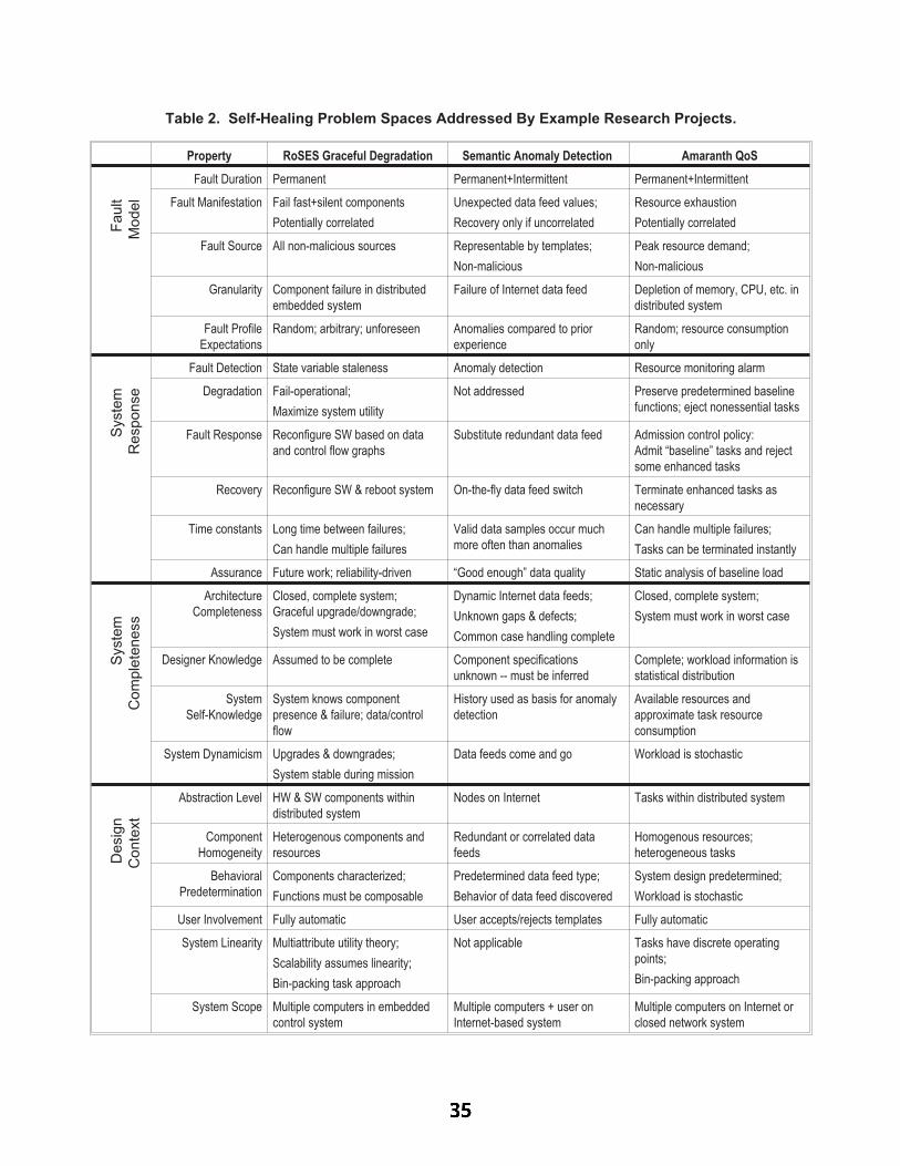
Property RoSES Graceful Degradation Semantic Anomaly Detection Amaranth QoS
Fault
Model
Fault Duration Permanent Permanent+Intermittent Permanent+Intermittent
Fault Manifestation Fail fast+silent components
Potentially correlated
Unexpected data feed values;
Recovery only if uncorrelated
Resource exhaustion
Potentially correlated
Fault Source All non-malicious sources Representable by templates;
Non-malicious
Peak resource demand;
Non-malicious
Granularity Component failure in distributed
embedded system
Failure of Internet data feed Depletion of memory, CPU, etc. in
distributed system
Fault Profile
Expectations
Random; arbitrary; unforeseen Anomalies compared to prior
experience
Random; resource consumption
only
Syste
m
Response
Fault Detection State variable staleness Anomaly detection Resource monitoring alarm
Degradation Fail-operational;
Maximize system utility
Not addressed Preserve predetermined baseline
functions; eject nonessential tasks
Fault Response Reconfigure SW based on data
and control flow graphs
Substitute redundant data feed Admission control policy:
Admit “baseline” tasks and reject
some enhanced tasks
Recovery Reconfigure SW & reboot system On-the-fly data feed switch Terminate enhanced tasks as
necessary
Time constants Long time between failures;
Can handle multiple failures
Valid data samples occur much
more often than anomalies
Can handle multiple failures;
Tasks can be terminated instantly
Assurance Future work; reliability-driven “Good enough” data quality Static analysis of baseline load
Syste
m
Com
ple
teness
Architecture
Completeness
Closed, complete system;
Graceful upgrade/downgrade;
System must work in worst case
Dynamic Internet data feeds;
Unknown gaps & defects;
Common case handling complete
Closed, complete system;
System must work in worst case
Designer Knowledge Assumed to be complete Component specifications
unknown -- must be inferred
Complete; workload information is
statistical distribution
System
Self-Knowledge
System knows component
presence & failure; data/control
flow
History used as basis for anomaly
detection
Available resources and
approximate task resource
consumption
System Dynamicism Upgrades & downgrades;
System stable during mission
Data feeds come and go Workload is stochastic
Desig
n
Conte
xt
Abstraction Level HW & SW components within
distributed system
Nodes on Internet Tasks within distributed system
Component
Homogeneity
Heterogenous components and
resources
Redundant or correlated data
feeds
Homogenous resources;
heterogeneous tasks
Behavioral
Predetermination
Components characterized;
Functions must be composable
Predetermined data feed type;
Behavior of data feed discovered
System design predetermined;
Workload is stochastic
User Involvement Fully automatic User accepts/rejects templates Fully automatic
System Linearity Multiattribute utility theory;
Scalability assumes linearity;
Bin-packing task approach
Not applicable Tasks have discrete operating
points;
Bin-packing approach
System Scope Multiple computers in embedded
control system
Multiple computers + user on
Internet-based system
Multiple computers on Internet or
closed network system
Table 2. Self-Healing Problem Spaces Addressed By Example Research Projects.

deed even apply to all research projects. Additionally, the
type of information required to describe many projects is
not fully available from published sources. In the interest
of providing concrete examples, three of our own research
projects are briefly described in terms of the proposed cate-
gories in Table 2.
RoSES (Robust Self-configuring Embedded Systems)
[Shelton03] is a project that is exploring graceful degrada-
tion as a means to achieve dependable systems. It concen-
trates on allocating software components to a distributed
embedded control hardware infrastructure, and is con-
cerned with systems that are entirely within the designer’s
control.
The semantic anomaly detection research project
[Raz02] seeks to use on-line techniques to infer specifica-
tions from underspecified components (e.g., Internet data
feeds) and trigger an alarm when anomalous behavior is ob-
served. An emphasis of the research is using a tem-
plate-based approach to make it feasible for ordinary users
to provide human guidance to the automated system to im-
prove effectiveness.
The Amaranth project [Hoover01] is a Quality of Ser-
vice project that emphasizes admission policies. A key idea
is to have tasks with at least two levels of service: baseline
and optimized. A system could thus be operated to
guarantee critical baseline functionality via static system
sizing, with idle resources employed to provide optimized
performance on an opportunistic per-task basis.
All three projects are, in our opinion, “self-healing soft-
ware system” research projects. But as shown by Table 2
they have widely varying areas of exploration, assump-
tions, and areas that are unaddressed. The area in which all
three projects are substantially similar is the last attribute,
in which all three systems assume a distributed computing
environment. It is worth noting that the categories were
created before Table 2 was constructed, so this provides ini-
tial evidence that the categories capture differences among
general projects rather than being specific to just these pro-
jects. But of course since the people involved in the three
projects discussed overlap, this does not prove generality
and certainly does not demonstrate completeness.
4. Conclusions
It is too soon to tell whether “self-healing” system ap-
proaches are just a different perspective on the area of fault
tolerant computing, and whether that perspective brings
significant benefits. Resolving this issue requires better un-
derstanding of what is meant by the term “self-healing” in
the first place. To that end, this paper proposes a taxonomy
for describing the problem space for self-healing systems.
Relevant aspects of self-healing system approaches in-
clude fault models, system responses, system complete-
ness, and design context. It is of course unreasonable to ex-
pect every research paper on self-healing systems to
address every possible aspect discussed, and no doubt some
important aspects are yet to be discovered. It remains to be
seen how different aspects interact in various domains, and
which aspects matter the most in practice. However, it is
hoped that this taxonomy will provide a checklist for re-
searchers to use in explaining the part of the problem space
they are addressing, and perhaps to help avoid inadvertent
holes in self-healing system approaches.
5. Acknowledgments
I would like to thank the participants of WOSS02 for
stimulating discussions that made this paper possible, the
anonymous reviewers for their comments, and the mem-
bers of my research group for their additional suggestions.
The techniques in this paper come from the experience of
others and decades of research, especially in the fault toler-
ant/dependable computing community. Interested readers
should consult the proceedings of the Fault Tolerant Com-
puting Symposium (FTCS) and Dependable Systems &
Networks (DSN) conference for further information.
This work was supported in part by the High Depend-
ability Computing Program via NASA Ames cooperative
agreement NCC-2-1298, and in part by the General Motors
Collaborative Research Laboratory at Carnegie Mellon
University.
6. References
[Avizienis01] A. Avizienis, J.-C. Laprie and B. Randell,Fundamental Concepts of Dependability, Research ReportN01145, LAAS-CNRS, April 2001.
[Bouricius69] Bouricius, W.G., Carter, W.C. & Schneider, P.R,“Reliability modeling techniques for self-repairing computersystems,” Proceedings of 24th National Conference, ACM, 1969,pp. 395-309.
[Hoover01] Hoover, C., Hansen, J., Koopman, P. & Tamboli, S.,“The Amaranth Framework: policy-based quality of servicemanagement for high-assurance computing,” InternationalJournal of Reliability, Quality, and Safety Engineering, Vol. 8,No. 4, 2001, pp. 1-28.
[Raz02] Raz, O., Koopman, P., & Shaw, M., “EnablingAutomatic Adaptation in Systems with Under-SpecifiedElements,” 1st Workshop on Self-Healing Systems (WOSS’02),Charleston, South Carolina, November 2002.
[Shelton03] Shelton, C., Koopman, P. & Nace, W., “A frameworkfor scalable analysis and design of system-wide gracefuldegradation in distributed embedded systems,” WORDS03,January 2003.
[vonNeuman56] von Neumann, J., “Probabilistic logics and thesynthesis of reliable organisms from unreliable components,”1956, in Taub, A. H., (ed.), John von Neumann: collected works,Volume V, pp. 329-378, New York: Pergamon Press, 1963.
[WOSS02] 1st Workshop on Self-Healing Systems (WOSS’02),Charleston, South Carolina, November 2002, ACM Press.

������������� ��� ���������������� ������� ����! "�$#
%'&)(�*,+.-�*0/21�&4325�-�6�7�*�8:9�;/2<=1�7>7@?A7�BDCE7@FHG�-�IJ;LK"/2<L&M;L*�<N;
OP?Q7�KJ&Q6�(SR�*TIU;LK.*V(WIJ&Q7@*V(W?AX"*�&ZY@;NKJ[J&ZI�\@3^]0&Q(�F_&`3�OPacb@b�dfe@eg IU[J1�&)h�d@3�1�;jilkWm�<L[NnpoV-qnr;N6�-
sut�vNwyx,zV{�w
|T}�~��Q�l�=�`�"�=�`���f���������Q�y�`�E�,�U���������H}�~��������`���U�����L��������}=����)�������l~�}��E�N�����p�j���������)}"�=�@�=���.�J�'�=�@�" U����� ~������U���)���¡���`}���������Q�Z����¢¤£¥}=�W��~��y�����M�Z}����=�J�@�`}4�������M�Z���q�4�Z¦A�����>�����¨§����=�����Q��}�~A���}�~��M�l���`�����U�������©�=���"�=�`�¥�����������Q�Z�=�j~�}����E�����4��������~��y�@��}�~��M��l�=�`�¥���U���)���¥ªA���y���=�������U���«��}�~��@}=����~��y�@���Q�Z}=�@�=�����`}��,�����Q�Z����«���r���4�E�l���������Q���=�Z������}=�¨�,���`�����)}P~��y�@���Q�Z}=�@�=�� U����� ¬^�����M�Z}�����S��,��¬¤�r���}�~���}�~��Q�l�=�`�"�=�`���f���������Q�y�`�J¢¥®A���~�}=���'�=�@�����=�@��j���,�����N�j���������M��=�4���'}U������}=�������������'�@}=�W��~��y�����M�Z}����=�,���`}���������Q�Z�������¯����~����Q�E�=�@�¥�¥�«�����Z}=���������M�Z���=�����U���)���¥��¢A|y°D±$�«�P�~��`�=�'���l}��`²�~�}��P�M������� ~��=���f�"���������������.�����L����}�~��M�l���`�����`���f����)�����M�y�`�"�=�@�¯���U�"�������:�f���4���)}³ =����� ~��´�� =�=���Z���M�S}�~¨~��y�@����M�Z}����=�T���`}��,�����M�Z����¢�µ��_���y�«�D�,���,����ªD�l�"�4¶N�)�����|y°P±·�V��������}J�4���U���M�Z�S��}=�����Q�������Z�¯��}¸��,���¥���'���=�¹���³�f���4�º�)}¸��}J�j����=���"�=�@�=���.�J���,���~�}=���'�=�@���E�����"�j���,�����N�j���������M�j¢
»V¼�½L¾ wfx�¿ÁÀ�¨{�w,Ã�¿ ¾
Ä�ÅDÅ�ÆjÇ�È�ÉqÊjË`Ì�Å`ÍyÅ�È4Ì�Î'ŨÏNÌ�Ì.ÐÑjË4Æ=ÉAÒrÓ,Ñ�ÒrÓ³Å`ÒÕÔ�Ì¥ÊjÓ�Ö�×�ÆjÎEØÐ,ÙrÌ�ÚyÒpÈ�ÍNÛ^Å`Æ�Ç�È�ÉÁÊ�Ë4Ì"Ê�Ë�×�Ü,ÒrÈ`ÌJ×�È`Ý�Ë`̯ÊjÅ�ʳÜ�ÒrÑNÜyØQÙÕÌ�ÞNÌ�ÙAÊ�ßWÅ�È4Ë4ÊN×�ØÈ`ÒÕÆjÓHÒ«Å�Æ�Ç�ÒrÓ�×�Ë`ÌJÊjÅ`ÒrÓ�Ñ�ÒÕÎ�ÐWÆNË�È�Ê�Ó�×�Ì�ÇÆNË�Ö,Ì.Å`ÒrÑNÓ,Ì�Ë�Å�È4Æ´Ë`ÌJÊ=ØÅ�ÆNÓ0Ê�ß�ÆjÝ,È"È4Ü,̺Å�ÆjÇ�È�ÉqÊjË`ÌSÅ�ÍyÅ�È`Ì�Î'Å�Ê�ÓWÖàÎ'Ê�ÏNÌ�ÌJÊ�Ë4ÙrÍàÖyÌ�ØÅ�ÒÕÑjÓ�ÖyÌ.×�ÒÕÅ`ÒÕÆjÓ�Å.álĨŨÊ�Ë`ÌJÅ�Ý,ÙrÈ.Û�Î�ÊjÓfÍ�Ê�Ë�×�Ü,ÒrÈ`Ì.×�È`Ý,Ë4ÌâÖyÌ.Å4×�Ë4ÒÕÐyØÈ`ÒÕÆjÓ�ÙÕÊjÓ,ÑjÝWÊ�ÑjÌJÅDãZĨäPå>Å�æÁÜ�ÊUÞNÌDßWÌ.Ì�Ó�Ð,Ë4ÆjÐ�ÆNÅ`Ì.ÖSçpèJéUêQáqëÆNÅ�ÈĨäPå>Å.ÛìÜ,Æ=ÉqÌ�ÞjÌ.Ë.Û�ÇÆy×�ÝWÅDÎ�ÊjÒrÓ�ÙrÍ�ÆNÓ�È4Ü,Ì�ÇÆjË4Î'Ê�Ù�Ó,Æ�È�Ê=È4ÒrÆNÓìÛÊ�Ó�ÖºÎ'ÊjÓLÍ´ÆjÇ�È`Ü,Ì.ÎíÖyÆSÓ,Æ�È�Æ�î@Ì�Ë�Ê�Ó�ÊjÙrÍLÈ4ÒÕ×.Ê�Ù^È`Ì.×�Ü�Ó,ÒÕïLÝ,ÌJÅÈ`ÆÞjÌ.Ë`ÒrÇÍ�È4Ü,Ì�Ð,Ë4ÆjÐ�Ì�Ë`È`ÒÕÌ.ÅDÆjÇÁÈ`Ü,Ì.ÒrË�Ö,Ì.Å`ÒrÑNÓ�Å�á�ðfÆjÎ�Ì�Ä�ä�å2ÅÖyÆ'Ð,Ë4Æ=ÞLÒ«ÖyÌâÊ�ÓWÊ�ÙÕÍNÈ4ÒÕ×.Ê�Ù@È4Ì.×�Ü,Ó,Ò«ïLÝ,Ì.Å.Û,ß,Ý,È�È`Ì.Ó�Ö"È`Æ�ÇÆy×�Ý�ŨÆjÓÊ¥ÐWÊ�Ë`È`Ò«×�Ý,Ù«Ê�ËAÐ,Ë4ÆjÐ�Ì�Ë`È�Í�Ê�ÓWÖ"ÙÕÌ.ÊUÞNÌDÆ�È`Ü�Ì�ËAÐ,Ë4ÆjÐ�Ì�Ë`È`ÒÕÌ.ÅÁÝ,Ó�Ì�ÚfØÐ,ÙrÆNË`ÌJÖTáuñ,ÆjË�Ì�ÚyÊjÎ�Ð,ÙrÌNÛ^òSË4ÒrÑNÜNÈ�ç óJê�ÊjÙrÙÕÆ=É�Å¥Ö,Ì.ÊjÖ,ÙrÆy×�ÏHÖyÌ�ØÈ`Ì.×�È`ÒÕÓ,Ñ�ô,ë�Ì�È4ÊNõöçpèJ÷Uê2ÊjÓ�Ö�ø�Ó,Òù^ÆjË4ÓSçrè.ú=ê2Å�Ý�Ð,ÐWÆNË�È�Å4×�Ü,Ì.Ö,ÝyØÙÕÊjß,ÒrÙÕÒrÈ�Í�Ê�Ó�ÊjÙrÍyÅ`ÒÕÅEçpèJéUê)áEû2Ư×�ÆjÓLÈ`Ë4ÒÕß,ÝyÈ`Ì¥È`ƯÈ4Ü,Ì'Ê�Ó�ÊjÙrÍyÅ`ÒÕÅ�Æ�ÇÅ�ÆjÇ�È�ÉqÊjË`̳ÊjË4×�Ü�ÒpÈ4Ì.×�È4Ý,Ë4Ì.Å.Û¨ÉqÌ�Ì�ÚLÈ4Ì�Ó�Ö |@}�~��M�l���`�³°��`���f����������M�y�`��±³}.�N��� ãQðyĨë�æ�ÉAÒrÈ`Ü�Å�È`Æy×�Ü�ÊNÅ�È4ÒÕ×�×�ÆjÓ�Å�È`Ë4Ý�×�È4ÅÁÇÆN˨Ó,ÆNÓyØÇÝ,Ó�×�È4ÒrÆNÓ�Ê�Ù>Ð,Ë`ÆNÐWÌ.Ë�È�Í�Ì�Þ=Ê�ÙÕÝ�Ê=È4ÒrÆNÓ"ÒÕÓÊjÖ,Ö,ÒpÈ4ÒrÆNÓ"È4Æ'ÒpÈ�ÅAÌ�ÚyÒ«Å�È`ØÒrÓ,Ñ'×.Ê�Ð�Êjß,ÒrÙÕÒrÈ�Í�Æ�Ç2ÇÝ,Ó�×�È4ÒrÆNÓ�Ê�Ù>Ð,Ë`ÆNÐWÌ.Ë�È�Í�ÞjÌ�Ë4ÒrüW×�Ê�È`ÒÕÆjÓìáð,ĨëýÒ«Å�ʯÇÆjË4Î'Ê�ÙVÇË�Ê�Î�Ì�ÉqÆjË4Ï�ÇÆjË¥Å�Ð�Ì.×�ÒpÇÍfÒÕÓ,Ñ�Ê�Ó�Ö´ÊjÓyØ
Ê�ÙÕÍLÔ.ÒrÓ�ÑSÅ`Æ�Ç�È�ÉÁÊ�Ë4ÌÊ�Ë�×�Ü,ÒpÈ4Ì.×�È`Ý,Ë4Ì.Å�çrè.þUê)áàÿ)È�Å`Ý,Ð,Ð�ÆjË`È4Å�Ü,ÒÕÌ�Ë`Ø
Ê�Ë�×�Ü,Ò«×�Ê�Ù@ÖyÌJ×�ÆjÎ�Ð�ÆNÅ`ÒpÈ4ÒrÆNÓ"ÊjÓ�Ö"ÊjÝyÈ`ÆNÎ'Ê=È`Ò«×PÊ�Ó�ÊjÙrÍyÅ`ÒÕÅ^Æ�Ç�Å�ÆjÇ�È�ØÉqÊjË`ÌÁÊ�Ë�×�Ü,ÒrÈ`ÌJ×�È`Ý�Ë`ÌJÅ�á>ä�Òrî�Ì.Ë`Ì.ÓNÈVÈ4Ì.×�Ü,Ó�ÒÕïLÝ,ÌJÅ�ÊjÓ�Ö�È`ÆfÆjÙ«Å�Ü�ÊUÞjÌßWÌ.Ì�Ó�ÝWÅ�ÌJÖPÈ`Æ�ÊjÓ�Ê�ÙÕÍfÔ�̤ÊPðyĨëöÎ�ÆyÖyÌ.ÙjÇÆNËìÈ`Ü�ÌlÌ�Þ=ÊjÙrÝ�Ê�È`ÒÕÆjÓâÆjÇÞ=Ê�Ë4ÒrÆNÝ�Å>Ð�Ë`ÆNÐWÌ.Ë�È4ÒrÌJÅ�Û=Ê�ÓWÖâÈ`Ü�ÌÁðyÄ�ë ÇË�Ê�Î�Ì.É^ÆNË`ÏPÜ�ÊjÅ2Ð,Ë4Æ=ÞjÌJÖÈ`Æ�ß�Ì�Ý�Å`Ì�ÇÝ�Ù^Ê�ÓWÖºÖyÌ.Å`ÒrË�Ê�ß�ÙrÌ'ÒÕÓ¸Å�Ð�Ì.×�ÒpÇÍfÒÕÓ,ѳÊjÓ�Ö´ÞjÌ.Ë`ÒrÇÍfÒrÓ,ÑÅ�ÆjÇ�È�ÉqÊjË`Ì�Ê�Ë�×�Ü,ÒpÈ4Ì.×�È`Ý,Ë4Ì.Å.á�ñ�ÆjËqÌ�Ú,Ê�Î�Ð,ÙÕÌjÛfÒÕÓ�çrè.þUê)ÛyË4Ì.Êj×�ÜWÊ�ß,ÒÕÙpØÒpÈ�Í�ÊjÓ�Ê�ÙÕÍyÅ�Ò«Å�È`ÌJ×�Ü,Ó,Ò«ïNÝ�Ì¥ÉÁÊjÅPÝ�Å`Ì.Ö�È`ÆÊ�Ó�ÊjÙrÍfÔ.Ì�È`Ü�Ì¥È4ÒrÎ�Ì.ÙrÒrØÓ,Ì.Å4Å�Æ�ÇWʨË`ÌJÊ�ÙNÈ`ÒÕÎ�ÌÁÅ`ÍyÅ�È4Ì�Î�á2ûÁÜ�ÌÁÅ`ÍfÎ�ß�ÆjÙÕÒÕ×lÎ�ÆfÖ,Ì�Ùy×�Ü,Ì.×�ÏNÌ�Ëðyë � ÉÁÊjÅ�Ý�Å�ÌJÖ�ÒrÓ¸çrè���ê>È`Æ�ÞjÌ�Ë4ÒrÇÍ�È`Ü�ÌâÇÝ,Ó�×�È`ÒÕÆjÓ�ÊjÙ2×�ÆNË`Ë4Ì.×�È�ØÓ,Ì.Å4ůÆ�Ç�Ê_×�ÆjÎ�Î�Ý,Ó�ÒÕ×.Ê=È`ÒÕÆjÓ0Ð,Ë4Æ�È`Æy×�ÆjÙQÛ�Ê�ÓWÖ È`Ü�Ì�È4Ü,Ì�ÆNË`Ì.ÎÐ,Ë4Æ=ÞjÌ�Ë�ðyû2Ì��uÉÁÊjÅÁÝWÅ�ÌJÖ�È4Æ'Ë`ÌJÊjÅ`ÆjÓ¯Ê�ß�ÆjÝyÈAÈ4Ü,Ì�×�ÆNË`Ë4Ì.×�È`Ó,ÌJÅ`ÅÆ�Ç�Ê�Ó�Ì�ÙÕÌ.×�È`Ë4ÆjÓ,Ò«×D×�ÆjÎ�Î�Ì�Ë�×�Ò«Ê�ÙTÅ`ÍyÅ�È4Ì�Î�ç ó�éUê)áû>Æ Ö,Ê=È4ÌjÛ¥È`Ü,Ì ðyÄ�ë ÇË�Ê�Î�Ì�ÉqÆjË4Ï0Î'ÊjÒrÓ,ÙÕÍ ÇÆy×�Ý�Å`Ì.Å�ÆjÓ
ÇÝ,Ó�×�È`ÒÕÆjÓ�ÊjÙ2Ð,Ë4ÆjÐ�Ì�Ë`È�Í"ÊjÓ�Ê�ÙÕÍyÅ�Ò«Å.á¨õ�Æ=ÉqÌ�ÞNÌ�ËJÛ,Ó,ÆjÓ,ØMÇÝ,ÓW×�È`ÒÕÆjÓWÊ�ÙÐ,Ë4ÆjÐ�Ì�Ë`È`ÒÕÌ.Å.ÛNÅ`Ý�×�Ü�ÊjÅlÐWÌ.Ë�ÇÆNË`Î'Ê�ÓW×�̨ÊjÓ�Ö'ÖyÌ�Ð�Ì�ÓWÖ,Ê�ß,ÒÕÙÕÒpÈ�ÍNÛfÊjË`ÌÆ�ÇDÈ`Ü�̳Å`ÊjÎ�ÌÒrÎ�Ð�ÆjË`È4Ê�ÓW×�ÌÈ4Æ´È`Ü,ÌSïNÝWÊ�ÙÕÒpÈ�Í_Æ�Ç�ʺÅ�ÆjÇ�È�ÉqÊjË`ÌÅ�ÍyÅ�È`Ì.ίá�ä�Ì�Ð�Ì�Ó�Ö,Êjß,ÒÕÙrÒrÈ�ÍjÛìÏfÓ,Æ=ÉAÓ´ÊjÅ�È4Ü,Ì'×�ÆjÙÕÙÕÌ.×�È4ÒrÆNÓ�ÆjÇ^Ë4Ì�ØÙrÒ«Ê�ß�ÒrÙÕÒpÈ�ÍNÛPÊUÞ=ÊjÒrÙ«Ê�ß,ÒÕÙÕÒpÈ�ÍNÛ�Å4Ê=ÇÌ�È�Í0Ê�Ó�Ö Ë`Ì.ÙÕÊ�È`Ì.Ö0Î�Ì.ÊNÅ�Ý,Ë4Ì.Å.Û¨Ò«ÅÌ.Å`ÐWÌJ×�Ò«Ê�ÙÕÙrÍ"×�ÆjÓW×�Ì�Ë4Ó,ÌJÖ�ÒÕÓÅ`Ê�ÇÌ�È�Í�ÊjÓ�Ö�Î�Ò«Å`Å`ÒÕÆjÓ×�Ë4ÒpÈ4ÒÕ×.Ê�ÙìÅ`ÍyÅ�ØÈ`Ì.ίá�ä�Òpî@Ì�Ë4Ì�ÓLÈ�ÎEÆyÖyÌ.ÙrÒÕÓ,ÑDÊ�Ó�Ö¥Ê�Ó�ÊjÙrÍfÔ.ÒrÓ,ѨÈ`ÌJ×�Ü,Ó,Ò«ïNÝ�Ì.Å�Ü�ÊUÞjÌßWÌ.Ì�Ó¥Ì�ÚyÐ,ÙÕÆjÒrÈ`Ì.Ö�È`Æ�Ì�Þ=Ê�ÙÕÝ�Ê=È4Ì^Þ=ÊjË`ÒÕÆjÝ�Å>Ó,ÆjÓ,ØMÇÝ,ÓW×�È`ÒÕÆjÓWÊ�ÙfÐ,Ë4ÆjÐyØÌ�Ë`È`ÒÕÌ.Å.á³ñ,ÆNË�Ì�ÚyÊjÎ�Ð,ÙrÌNÛ�ÇZÊ�Ý,ÙrÈ�ØQÈ`Ë4Ì�ÌJÅ�ÉqÌ�Ë4Ì�Ý�Å`Ì.Ö´ÇÆNË¥Å`ÍfÅ�È`Ì.ÎË`Ì.ÙrÒ«Ê�ß�ÒrÙÕÒpÈ�ͳÎEÆyÖyÌ.ÙrÒÕÓ,ÑHçrèjè�êQôVïLÝ,Ì�Ý�ÒrÓ,ÑÓ�Ì�È�ÉqÆjË4ÏfÅDÜWÊUÞjÌ�ßWÌ.Ì�ÓÝ�Å`Ì.ÖDÇÆNË2Ð�Ì�Ë`ÇÆjË4Î'Ê�Ó�×�Ì^Ê�ÓWÊ�ÙÕÍfÅ`Ò«ÅìÆ�Ç�×�ÆjÎ�Ð,Ý,È`Ì�Ë�Ê�ÓWÖ�×�ÆNÎEÎ¥ÝyØÓ,Ò«×�Ê=È4ÒrÆNÓ¸Å�ÍyÅ�È`Ì.Î�Å"çpèNÛ^èUóJê)ôlÊÞ=Ê�Ë4ÒrÌ�È�Í�ÆjÇ |W��}.���,�=���Q�Z��®A���M���£����Z� ãQð�����Å4æ�Û�ÊNÅ�Ê�×�ÆjÓfÞjÌ.Ó,ÒrÌ.ÓLÈDÜ�ÒrÑNܺÙrÌ.ÞjÌ�ÙlÇÆjË4Î'Ê�ÙÕÒÕÅ`Î�ÆjÇë�Ê�Ë4ÏjÆ=Þ�×�ÜWÊ�ÒÕÓ�Å�Û2Ü�ÊUÞjÌ�ß�Ì.×�ÆjÎ�Ì'ÐWÆNÐ,Ý,Ù«Ê�ËâÇÆNËDÈ`Ü,Ì"Ê�Ó�ÊjÙrÍyÅ`ÒÕÅÆ�ÇfÐWÌ.Ë�ÇÆNË`Î'ÊjÓ�×�ÌNÛJÖyÌ.ÐWÌ.Ó�Ö,Êjß,ÒrÙÕÒrÈ�ÍPÊjÓ�ÖPÐWÌ.Ë�ÇÆNË`Î'Ê�ß�ÒrÙÕÒpÈ�ÍEç yÛ.þUê)áÿ�ÓÎ�ÆNÅ�ȨË`ÌJÅ�ÌJÊ�Ë�×�Ü"ÉqÆjË4Ï@ÛyÇÝ,Ó�×�È`ÒÕÆjÓ�ÊjÙ>Ð,Ë4ÆjÐ�Ì�Ë`È`ÒÕÌ.ŨÊ�Ó�Ö�Ó,ÆNÓyØÇÝ,Ó�×�È`ÒÕÆjÓ�ÊjÙTÐ,Ë`ÆNÐWÌ.Ë�È4ÒrÌJÅÁÊ�Ë4Ì�Å`Ì�Ð�ÊjË4Ê�È`Ì�ÙÕÍ'Î�ÆyÖyÌ�ÙÕÌ.Ö¯Ê�Ó�Ö�Ì�Þ=Ê�ÙrØÝ�Ê=È4Ì.ÖHßWÌJ×�Ê�ÝWÅ�̯Æ�Ç�È`Ü,Ì�×�ÆNÎEÐ�ÙrÌ�ÚfÒrÈ�ͺÆ�ÇPÒrÓLÈ4Ì�ÑjË�Ê=È4ÒrÆNÓìá¸ûÁÜ,ÌÅ�Ì.Ð�Ê�Ë�Ê=È4ÒrÆNÓDÌ.ÊjÅ`Ì.ÅìÈ`Ü,Ì^É^ÆNË`Ï�Æ�Ç,Î�ÆyÖyÌ�ÙÕÒÕÓ,ѨÊ�ÓWÖ�Ê�Ó�ÊjÙrÍyÅ`ÒÕÅ.ÛJß,ÝyÈÒÕÅ�Ð,Ë`ÆNÓ,ÌDÈ`Æ'ÒÕÓ�×�ÆjÓ�Å`ÒÕÅ�È`Ì.Ó�×�Í�Æ�ÇVÎ�ÆfÖ,Ì�Ù«Å�Ê�Ó�Ö¯ÒÕÎ�Ð,Ë`ÌJ×�Ò«Å�ÒÕÆjÓ�ÆjÇÌ�Þ=Ê�ÙÕÝ�Ê�È`ÒÕÆjÓ�Å.á�ò ÒrÈ`Ü´ÒÕÓ�×�ÆNË`Ð�ÆjË�Ê=È4Ì.Ö�Å�È`Æy×�Ü�ÊNÅ�È4ÒÕ×E×�ÆNÓ�Å�È4Ë`ÝW×�È4Å.ÛÈ`Ü,Ì´ðyĨë ÎEÆyÖyÌ.ÙP×.Ê�Ó ß�̳È4Ë4ÊjÓ�Å�ÇÆjË4ÎEÌJÖ_È`Æ_Ê_ðLÈ`Æy×�Ü�ÊNÅ�È4ÒÕ× Ì�ÉÁÊ�Ë�Ö���Ì�È�ç Jê�ãMð ��æ¨Î�ÆfÖ,Ì�ÙQá�ò Ü,ÒÕÙÕÌ�ÇÝ,ÓW×�È`ÒÕÆjÓWÊ�Ù�Ð,Ë4ÆjÐyØÌ�Ë`È�ͨÞNÌ�Ë4ÒpüW×.Ê=È4ÒrÆNÓPÒ«Å�×�ÆjÓWÖyÝ�×�È4Ì.ÖDÝ�Å`ÒÕÓ,ÑAÈ`Ü�̤È`ÌJ×�Ü,Ó,Ò«ïLÝ,Ì.Å>ÎEÌ.ÓyØÈ`ÒÕÆjÓ,ÌJÖuÊ�ß�Æ=ÞjÌjÛ^ÐWÌ.Ë�ÇÆNË`Î'ÊjÓ�×�Ì�Ê�Ó�ÖuÖyÌ.ÐWÌ.Ó�Ö,Êjß,ÒrÙÕÒrÈ�Í_×�ÊjÓ_ß�ÌÌ�Þ=Ê�ÙÕÝ�Ê�È`ÒÕÆjÓ¯ßLÍ"Å�ÆNÙrÞfÒÕÓ,ÑEÈ`Ü,Ì�ÖyÌ.Ë`ÒÕÞjÌJÖ"ð � Î�ÆfÖ,Ì�ÙQáûÁÜ,Ì'Ë`ÌJÅ�ÈâÆjÇ^È4Ü,Ì�Ð�Ê�Ð�Ì�ËâÒ«ÅâÆjË4ÑNÊjÓ,ÒÕÔ�Ì.Ö�ÊjÅ�ÇÆjÙÕÙÕÆ=É�Å�á�ðfÌJ×�Ø

È`ÒÕÆjÓ ó:ÒrÓLÈ4Ë`ÆyÖyÝ�×�Ì.Å�ðyÄ�ë Ê�Ó�Ö ð �¨Å.á�ÿ�Ó Å`Ì.×�È4ÒrÆNÓ ú,Û�ÊÎ�Ý,ÙrÈ`ÒÕÐ,Ë4Æf×�Ì.Å4Å�ÆN˨Å`ÍfÅ�È`Ì.Î�Ò«Å�ÑNÒrÞNÌ�Ó�ÊNŨÊ�Ó³Ë`Ý,Ó�Ó,ÒrÓ�Ñ�Ì�Ú,Ê�Î�Ð,ÙÕÌÈ`Ü,Ë4ÆjÝ,ÑNÜ,ÆjÝ,ȤÈ`Ü,ÌPÐ�ÊjÐWÌ.Ë.á¤ðfÌJ×�È`ÒÕÆjÓ��¥ÖyÌ.Ð,ÒÕ×�È4Å^È`Ü�Ì�Å�È`Æy×�Ü�ÊjÅ�È`Ò«×Ì�ÚfÈ`Ì.Ó�Å�ÒÕÆjÓ�ÆjÓ¥ðyÄ�ëºÛ=Ê�Ó�Ö�Å�ÌJ×�È`ÒÕÆjÓ AÌ�ÚyÐ,Ù«Ê�ÒÕÓ�Å2Ü,Æ=ÉSÈ`ƨÈ`Ë�Ê�Ó�Å�ØÇÆjË4Î È`Ü,Ì�ðyÄ�ë Î�ÆyÖyÌ�ÙVÒÕÓLÈ`Æ�Ê�Óºð ��áìûÁÜ,Ì�Ë`ÌJÅ�Ý,ÙrÈ4ÅPÆjÇlË`Ì�ØÙrÒ«Ê�ß,ÒÕÙÕÒpÈ�Í�ÊjÓ�Ê�ÙÕÍyÅ�Ò«ÅqÇÆjË�È`Ü,ÌâÌ�ÚyÊjÎ�Ð,ÙrÌ�Å`ÍyÅ�È4Ì�ΩÊ�Ë4ÌDÖ,Ì.Å4×�Ë4Òrß�Ì.ÖÒrÓ�Å�ÌJ×�È4ÒrÆNÓ���Û,Ê�Ó�Ö¯×�ÆNÓ�×�ÙÕÝ�Å`ÒrÆNÓ�ÅAÊ�Ë4ÌDÖyË4ÊUÉAÓ¯ÒÕÓ�Å`Ì.×�È`ÒÕÆjÓ��fá
�Á¼������ x � à ��� ¿�����¿¤x��cz! �Ã�v"� v
û2Æ�ÑjÒÕÞjÌ�Ë4Ì.ÊjÖ,Ì�Ë�Å�ʯË4ÆjÝ,ÑNܳҫÖyÌ.Ê�Ê�ß�ÆjÝ,ÈâÈ`Ü,ÌEÇÆjË4Î'Ê�ÙÕÒÕÅ`Î'ÅÝ�Å�ÌJÖ�ÒÕÓ¥È`Ü,Ò«Å�Ð�Ê�Ð�Ì�ËJÛ�ÉqÌ^ß�Ë`ÒÕÌ$#�Í�ÒrÓLÈ`Ë4ÆyÖyÝ�×�ÌÁðyÄ�ë Ê�Ó�Ö�ð ��á
2.1. Software Architecture Model
ð,Ĩë Ò«Å�ÊEÇÆjË4Î'Ê�Ù@ÇË�Ê�Î�Ì�ÉqÆjË4Ï�ÇÆj˨Å`Ð�Ì.×�ÒrÇÍfÒrÓ�Ñ�Ê�Ó�Ö�Ê�ÓWÊ=ØÙrÍfÔ�ÒÕÓ,ÑPÅ�ÆjÇ�È�ÉqÊjË`̤ÊjË4×�Ü,ÒrÈ`ÌJ×�È4Ý,Ë`ÌJÅ�á2Ä:ðyÄ�ë Î�ÆyÖyÌ�Ùy×�ÆjÓ�Å`ÒÕÅ�È4Å>Æ�ÇÊâÅ�Ì�ÈlÆ�Ç ��}=�¨�,}=�����M�Z}��,� ÊjÓ�Ö'Ê �f�Z���`���`�4�y�Z���=�T�'�4�j�@���L� Ë4Ì�Ù«Ê=È`ØÒrÓ,ѨÈ`Ü,ÌÁ×�ÆNÎ�ÐWÆLÅ�ÒrÈ`ÒÕÆjÓ�Å.á2Ä:×�ÆNÎ�ÐWÆLÅ�ÒrÈ`ÒÕÆjÓ�ÒÕÓ¥È`Ý,Ë4Ó�×�ÆNÓ�Å`ÒÕÅ�È4Å2Æ�ÇÎ�Ý,ÙrÈ`ÒÕÐ,ÙÕÌ ��}=�¨�,}��������M� ÊjÓ�Ö ��}=���@������}=��� ÛfÊ�Ó�Ö�ÊâÅ`Ì�ÈlÆjÇ@×�ÆjÎEØÐWÆLÅ�ÒrÈ`ÒÕÆjÓ ��}��,���M�4�=�����M� á&%^Êj×�ܸ×�ÆNÎ�ÐWÆNÓ,Ì�ÓLȯãZÆjËE×�ÆjÓ�Ó,Ì.×�È`ÆjË�æ×�ÆjÓWÅ�Ò«Å�È�ÅâÆ�ǨÊ�ßWÌ.Ü�ÊUÞfÒrÆNË�Î�ÆfÖ,Ì�Ù^ÊjÓ�Ö¸Ê�Å`Ì�È¥Æ�Ǩ×�ÆNÎ�ÐWÆNÓ,Ì�ÓLÈãÆjËq×�ÆNÓ,Ó,Ì.×�È`ÆNË�æV×�ÆjÓ�Å�È`Ë�Ê�ÒÕÓLÈ4Å.á�ĹðyĨë�Î�ÆfÖ,Ì�Ù�ÒÕÅqÅ`ÊjÒÕÖEÈ4Æ�ß�Ì×�ÆjË4Ë4Ì.×�È�ÒpǤÈ4Ü,ÌEßWÌ.Ü�ÊUÞfÒrÆNË�Î�ÆyÖyÌ�Ù«ÅPÅ`Ê�È`Ò«Å�ÇÍÌJÊj×�ܳ×�ÆjÓ�Å�È`Ë�Ê�ÒÕÓLÈ.áñ,ÆjË�Ê"ÇÆNË`Î'Ê�Ù¤Ö,Ì�ü�Ó,ÒrÈ`ÒÕÆjÓºÊjÓ�Ö�Ö,Ì.Å4×�Ë4ÒrÐyÈ4ÒrÆNÓ�ÆjÇAð,ĨëºÛìË4Ì�ÇÌ.ËÈ`Æç ÷�êQáûÁÜ�Ì�Ë4Ì�Ê�Ë4Ì�È�É^Æ�×�ÆjÎ�Ð,ÙÕÌ�Î�Ì�ÓLÈ�ÇÆNË`Î'ÊjÙlÎ�Ì�È4Ü,ÆyÖ,Å�Ý,ÓWÖyÌ�Ë`Ø
ÙrÍfÒÕÓ,Ñ"ʯðyĨë ÎEÆyÖyÌ.ÙMá'��Ì�È`Ë4Ò2Ó,Ì�È4ÅDÊ�Ë4Ì�Ý�Å`Ì.Ö�È`ƯÖyÌ�ü�Ó�Ì�È4Ü,ÌßWÌ.Ü�ÊUÞfÒrÆNË�Î�ÆfÖ,Ì�Ù«Å�ÆjǨ×�ÆjÎ�Ð�ÆjÓ,Ì.ÓLÈ4ÅEÊ�Ó�Öº×�ÆjÓ,Ó,ÌJ×�È4ÆjËJÛ�ÉAÜ�ÒrÙÕÌÈ`Ì�Î�Ð�ÆjË�Ê�ÙqÙrÆNÑjÒ«×'Ò«Å¥ÝWÅ�ÌJÖ´È`Æ´Å�Ð�Ì.×�ÒpÇÍ´È4Ü,Ì"×�ÆjÓ�Å�È`Ë�Ê�ÒÕÓLÈ4Å.áSû2ÆßWÌ(#�Ì�ÚyÒrß,ÙÕÌjÛìÈ`Ü,Ì'Ý,ÓWÖyÌ�Ë4ÙrÍfÒÕÓ,ѯÇÆjË4Î'Ê�Ù�ÇÆjÝ�Ó�Ö,Ê=È4ÒrÆNÓ�ÆjÇAð,ĨëÒÕÅDÓ,ÆjÈâÙrÒÕÎ�ÒpÈ4Ì.Ö�È`Æ�Ê"ü,ÚyÌ.Ö�Ð�ÊjÒrËâÆjÇ)��Ì�È4Ë`Ò�Ó,Ì�È�Ê�Ó�Ö³È`Ì.Î�ÐWÆjØË4ÊjÙlÙÕÆjÑjÒ«×�á�ûÁÜ�Ì"Å`Ì�ÙÕÌ.×�È4ÒrÆNÓ¸Æ�Ç�ʳÐ�Ê�Ë`È`Ò«×�Ý,Ù«Ê�Ë*��Ì�È`Ë4ÒlÓ�Ì�È'Ê�Ó�ÖÈ`Ì�Î�Ð�ÆjË�Ê�Ù�ÙÕÆjÑjÒ«×¥ÒÕÅPß�ÊNÅ�ÌJÖ�ÆjÓ�È`Ü�Ì�ÊjÐ,Ð,ÙÕÒÕ×.Ê=È4ÒrÆNÓ³Ý,Ó�Ö,Ì�Ëâ×�ÆNÓyØÅ�Ò«ÖyÌ�Ë�Ê=È4ÒrÆNÓìá�ñ,ÆjËAÌ�Ú,Ê�Î�Ð,ÙÕÌjÛyË4Ì.Ê�ÙrØQÈ`ÒÕÎEÌ'��Ì�È`Ë4ÒTÓ,Ì�È�ÅAÊ�Ó�Ö¯Ë4Ì.Ê�ÙrØÈ`ÒÕÎEÌ�×�ÆjÎ�Ð,ÝyÈ�Ê=È4ÒrÆNÓ�Ê�Ù@È4Ë`Ì.ÌPÙÕÆjÑNÒÕ×�ÉqÌ�Ë4ÌPÝWÅ�ÌJÖ�È4Æ'Å�È4Ý�ÖyÍ"Å`Æ�Ç�È`ØÉqÊjË`Ì�ÊjË4×�Ü,ÒrÈ`ÌJ×�È4Ý,Ë`ÌJÅ�ÆjǤË`ÌJÊ�ÙrØMÈ4ÒrÎ�Ì¥Å`ÍyÅ�È4Ì�Î'Å�çrè.þ=êQÛ ®q�`�����Z�4���)�+ �`���,�����Q�Z}=�º�����M� ã,�lË4û Ó,Ì�È4Å�æ¨ÊjÓ�Ö�ü�Ë�Å�ÈPÆNË4ÖyÌ.˨ÙÕÒrÓ�Ì.Ê�Ë�È`ÒÕÎ�ÌÈ`Ì�Î�Ð�ÆjË�Ê�Ù�ÙrÆNÑjÒ«×�ÉqÌ�Ë4Ì�Ý�Å`Ì.Ö�È`Æ"Å`Ð�Ì.×�ÒrÇÍ�Ê�ÓWÖ�ÞjÌ.Ë`ÒrÇÍÊ�×�ÆjÎEØÎ�Ý,Ó,Ò«×�Ê�È`ÒÕÆjÓ¯Ð,Ë4Æ�È`Æy×�ÆjÙVçpè��=ê)áÿ�Ó�È4Ü,Ò«ÅVÐ�Ê�Ð�Ì�ËJÛjÉqÌAÝ�Å`Ì-�¤Ë�ûHÓ�Ì�È4ÅlÊjÅ�È4Ü,Ì�ß�Ì�Ü�ÊUÞfÒÕÆjËVÎ�ÆyÖfØ
Ì�ÙÕÒrÓ,Ñ�ÇÆjË4Î'Ê�ÙÕÒÕÅ`Î Æ�ǤÈ4Ü,Ì�ð,Ĩë ÇË�Ê�Î�Ì.É^ÆNË`Ï@á.�lË4û Ó�Ì�È4ÅPÊ�Ë4ÌÊ�×�Ù«ÊjÅ4Å�ÆjǤÜ,ÒrÑNÜ�ÙÕÌ�ÞjÌ.Ù/��Ì�È`Ë4Ò>Ó,Ì�È4Å.á�ø¨Å`ÒÕÓ,Ñ�È4Ü,Ì¥×�ÆjÓfÞjÌ.ÓNÈ4ÒrÆNÓ�ÅÊ�Ó�ÖSÖyÌ�üWÓ,ÒpÈ4ÒrÆNÓ�ÅâÒÕÓ ç ÷Uê)Û2Ê��lË4û Ó,Ì�È�Ò«Å�ÖyÌ�ü�Ó,Ì.Ö´ÊNÅâÊ�È4Ý,Ð,ÙÕÌã,0�132547698:1<;>=@?Uæ�Û�ÉAÜ�Ì�Ë4Ì�0BA�ãDCE1GF-1IH�æ�Ò«Å�È4Ü,̯Ó,Ì�È�Å�È4Ë`Ý�×�ØÈ`Ý,Ë4Ìjô-254J6K8"ÖyÌ�üWÓ,Ì.Å¥È`Ü�ÌÝ�Å�ÌJÖHÅ`ÆjË`È4Å.Û¤ÆjÐ�Ì�Ë�Ê=È4ÒrÆNÓ�Å�Ê�Ó�ÖHË`Ì�ØÙÕÊ�È`ÒÕÆjÓ�Å.ô¤Ê�Ó�ÖL;>=@?�A�ã,M)1IN-1<O 13PRQJæ�ÖyÌ�ü�Ó�Ì.Å�È`Ü,Ì"Î�ÊjÐ,Ð,ÒÕÓ,ÑÆ�Ç�Ð,Ù«Êj×�Ì.Å'È4Æ_Å`ÆjË`È4Å.ÛÁÈ`Ü,ÌSÙ«Ê�ß�Ì�Ù«Å�ÛAÈ4Ü,Ì�×�ÆjÓ�Å�È`Ë�Ê�ÒÕÓLÈ�Æ�Ç�ÌJÊj×�ÜÈ`Ë�Ê�Ó�Å`ÒpÈ4ÒrÆNÓìÛ@Ê�Ó�Ö�È`Ü,ÌEÒrÓ�ÒpÈ4ÒÕÊjÙ�Î'ÊjË`ÏfÒÕÓ,Ñ�Ë4Ì.Å`ÐWÌJ×�È`ÒÕÞjÌ.ÙrÍNáâñ,ÆjËDÊ×�ÆjÎ�Ð,ÙÕÌ�È4ÌâÖyÌ�ü�Ó�ÒpÈ4ÒrÆNÓ¯ÆjÇ�Ê(�lË4û Ó,Ì�ÈJÛ,Ë`Ì�ÇÌ�ËqÈ`Æ�ç ÷Uê)á
2.2. Stochastic Reward Net
ð �íç Uê¨Ò«Å'Ê�ÓuÌ�ÚLÈ4Ì�Ó�Å`ÒÕÆjÓ_È`ÆHð��S��álÄ¨Ó ð �$×�ÊjÓ_ß�ÌÎ'Ê�Ð,Ð�Ì.Ö´ÒÕÓLÈ`Æ�Êë�ÊjË`ÏNÆ=Þ Ì�ÉÁÊ�Ë�ÖSÎEÆyÖyÌ.Ù¨ç Uê)á�TqÍSÖ,Ì�ü�Ó,ÒrØÈ`ÒÕÆjÓìÛWÊ�Óð � Ò«Å�Ê�ÓSèjè�ØMÈ4Ý,Ð,ÙÕÌD×�ÆjÓ�Å`Ò«Å�È4ÒrÓ,ÑEÆ�ÇVUèjáAĹü�Ó,ÒrÈ`Ì�Å`Ì�È�ÆjÇ2Ð,Ù«Êj×�Ì.Å.áóyáAĹü�Ó,ÒrÈ`Ì�Å`Ì�È�ÆjÇ>È4Ë4ÊjÓ�Å�ÒrÈ`ÒÕÆjÓWÅ�áú,áAĹü�Ó,ÒrÈ`Ì�Å`Ì�ÈAÆjÇ�ÒÕÓ,Ð,ÝyȨÊjË4×.ÅqÇË`ÆNÎ Ð,Ù«Êj×�Ì�È4ÆEÈ`Ë�Ê�Ó�Å`ÒpÈ4ÒrÆNÓìá��áAÄ_ü�Ó,ÒrÈ`Ì�Å`Ì�ÈVÆ�ÇWÆjÝyÈ4Ð,ÝyÈlÊ�Ë�×�Å>ÇË4ÆjÎ È4Ë4ÊjÓ�Å�ÒrÈ`ÒÕÆjÓ�È`ÆDÐ,Ù«Êj×�ÌjáyáAÄ üWÓ,ÒpÈ4Ì¥Å`Ì�ÈPÆ�ÇVÒrÓ�Ü,Òrß�ÒpÈ4ÆjËDÊ�Ë�×�ÅÁÇË4ÆjΩÐ,Ù«Êj×�Ì�È`Æ�È4Ë4ÊjÓ�Å`ÒpØÈ`ÒÕÆjÓ>á
�,áW%¤ÓWÊ�ß,ÙÕÒrÓ�ÑAÇÝ,Ó�×�È`ÒÕÆjÓ�ÇÆNË>ÌJÊj×�ÜDÈ`Ë�Ê�ÓWÅ�ÒrÈ`ÒÕÆjÓìá�ĺÈ4Ë4ÊjÓ�Å�ÒrÈ`ÒÕÆjÓҫůÖ,ÒÕÅ4Ê�ß,ÙÕÌ.ÖàÒpÇ�È4Ü,Ì´Ì�Ó�Êjß,ÙÕÒrÓ,ÑHÇÝ,Ó�×�È`ÒÕÆjÓ Ò«Å¯Ì�Þ=Ê�ÙÕÝ�Ê�È`Ì.ÖÇZÊ�Ù«Å`Ìjá
�fáW�¤Ë4ÒÕÆjË4ÒpÈ4ÒrÌJÅlÇÆNËAÌ.ÊN×�Ü�È4Ë4ÊjÓ�Å�ÒrÈ`ÒÕÆjÓWÅ�áVĹÈ`Ë�Ê�ÓWÅ�ÒrÈ`ÒÕÆjÓ¯ÒÕŨÖyÒÕÅ�ØÊ�ß�ÙrÌJÖ³ÒrÇlÈ4Ü,Ì�Ë4Ì�Ì�ÚyÒÕÅ�È4ÅDÊjÓ�Ì.Ó�Ê�ß,ÙÕÌ.Ö�È`Ë�Ê�Ó�Å`ÒrÈ`ÒÕÆjÓSÉAÒpÈ4ÜSÊÜ,ÒÕÑjÜ,Ì.ËAÐ,Ë4ÒrÆNË`ÒrÈ�Íjá
÷,áAûÁÜ,ÌâÒÕÓ,ÒrÈ`Ò«Ê�ÙTÎ'Ê�Ë4ÏfÒrÓ,ÑWáþ,áAÄ�ÐWÆLÅ�ÒrÈ`ÒÕÞjÌ�Ì�ÚyÐWÆNÓ,Ì�ÓLÈ4ÒÕÊjÙPÖyÒ«Å�È`Ë4Òrß,Ý,È`Ì.Ö Ë4Ê�È`̳ÇÆj˯Ì.Êj×�ÜÈ`ÒÕÎ�Ì.ÖDÈ4Ë4ÊjÓ�Å`ÒpÈ4ÒrÆNÓìÛ=Ê�Ó�Ö�ÊjÓ�ÒÕÎEÎ�ÌJÖyÒÕÊ�È`ÌlÈ`Ë�Ê�Ó�Å`ÒpÈ4ÒrÆNÓDü�Ë4Ì.ÅÊ=ÈAÓ,Æ�È4ÒrÎ�ÌNá
èJé,áAÄ ÉqÌ�ÒÕÑjÜLÈÁÇÆjËAÌ.ÊN×�Ü�È4Ë4ÊjÓ�Å`ÒpÈ4ÒrÆNÓìáèNèjá Ì.ÉqÊjË4Ö�ÎEÌJÊjÅ`Ý,Ë4Ì.Å.áð����.� çpè9Jê�ÊjÓ�Ö�ðyë�Ä ûcç ��ê�Ê�Ë4ÌDÈ�É^Æ�È4ÆfÆjÙ«ÅÁÇÆjË�ð �¨Å.á
TqÍ�Å`ÆjÙÕÞLÒÕÓ,ѯÈ`Ü�Ì�Ý,Ó�ÖyÌ.Ë`ÙÕÍfÒrÓ�Ñ�ë�Ê�Ë4ÏjÆ=Þ�×�Ü�ÊjÒrÓWÅâÆ�ÇAÊ�Ó¸ð ��ÛÐWÌ.Ë�ÇÆNË`Î'ÊjÓ�×�̳ÊjÓ�Ö Ö,Ì�Ð�Ì�Ó�Ö,Êjß,ÒÕÙrÒrÈ�Í Æ�ÇâÈ4Ü,Ì�Î�ÆyÖyÌ.ÙD×.Ê�Óàß�ÌÌ�Þ=Ê�ÙÕÝ�Ê�È`Ì.Öìá
XÁ¼ sZYíÂ. �w,ÃV[�x,¿A{ � vfvN¿lx]\_^Az!�`[a �
ò�ÌâÝ�Å`ÌâÊEÎ�Ý,ÙrÈ`ÒÕÐ,Ë4Æf×�Ì.Å4Å�ÆNËqÅ`ÍyÅ�È4Ì�Î Ö,Ì�Ð,Ò«×�È4Ì.Ö"ÒrÓºç úUê2ÊjÅÁÊË`Ý�Ó,Ó,ÒÕÓ,Ñ�Ì�Ú,ÊjÎEÐ�ÙrÌ�È`Æ�Ö,Ì�Î�ÆjÓ�Å�È`Ë�Ê=È4Ì'È`Ü�Ì�Ý�Å`Ì�ÆjÇÁÌ�ÚfÈ`Ì�ÓWÖyÌ.ÖðyĨë¸á�ĨÅAÒÕÙÕÙrÝ�Å�È`Ë�Ê=È4Ì.Ö¯ÒÕÓ�ñ�ÒÕÑjÝ,Ë4Ì�èjÛ,Ê�Î¥Ý,ÙpÈ4ÒrÐ�Ë`Æy×�ÌJÅ`Å`ÆjËAÅ`ÍyÅ�ØÈ`Ì.Î ×�ÆNÓ�Å�Ò«Å�È4ÅqÆ�Çb=³Å�Ý�ß�Å�ÍyÅ�È`Ì.Î�Å-2/c91�d�d�d$132�e@á�%lÊN×�Ü"Å`Ý,ß�Å`ÍyÅ�ØÈ`Ì.Î`2�f�ÒÕÅ�×�ÆjÎ�ÐWÆLÅ�ÌJÖ�ÆjÇ�ÆjÓ,ÌqÐ,Ë4Æy×�Ì.Å4Å`ÆjË/Cbf`Û�ÆjÓ,ÌqÙÕÆf×.Ê�ÙfÎ�Ì�ÎEØÆjË4Í�P�f�Û2Ê�Ó�Öhg Ë`Ì.Ð,ÙrÒ«×�Ê�È`ÌJÖ�Î�ÒrË4Ë4ÆjË4Ì.Ö�ÖyÒ«Å`Ï�Ý,Ó,ÒrÈ4Å'i(fkjjá¥Äß,Ý�Åml ×�ÆNÓ,Ó,Ì.×�È4Å2È`Ü�ÌS=�Å`Ý,ß�Å`ÍyÅ�È4Ì�Î'Å�Ê�Ó�Ö¥Ê�Å`Ü�ÊjË`ÌJÖâÎ�Ì�Î�ÆjË4ÍPRnLÛ�ÉAÜ�ÒÕ×�Ü�Ò«ÅPÅ�Ü�ÊjË`ÌJÖ�ßfͯÊjÙrÙ�Å�Ý�ß�Å�ÍyÅ�È`Ì.Î�Å.á�ûÁÜ�Ì¥×�ÆNÎ�Ð,ÙrÌ�È`ÌÅ�ÍyÅ�È`Ì.Î0ÇZÊjÒrÙ«ÅìÉAÜ�Ì�Ó�È4Ü,Ìlß�Ý�Å/làÇZÊ�ÒÕÙÕÅ2ÆjË2ÉAÜ,Ì�Ó(o�ã�è'pqo�pr=>æÅ�Ý�ß�Å�ÍyÅ�È`Ì.Î�ŨÇZÊ�ÒÕÙQá�Ä¡Å`Ý,ß�Å`ÍyÅ�È4Ì�Î ÇZÊjÒr٫ŨÉAÜ�Ì�ÓSÒpÈ�Å�Ð�Ë`Æy×�ÌJÅ`Å`ÆjËÇZÊ�ÒÕÙÕŨÆjËPÊ�ÙÕÙ2ÒrÈ4ÅPÖyÒ«Å�ÏyÅAÇZÊjÒrÙ�ÆjË�ßWÆjÈ`ÜÈ4Ü,ÌEÙrÆy×�ÊjÙ>Î�Ì�Î�ÆNË`Í�Ê�Ó�ÖÈ`Ü,Ì�Å`Ü�ÊjË`ÌJÖ�Î�Ì�Î�ÆjË4Í'ÇZÊjÒrÙQáûÁÜ,Ì'Ë`Ì.ÙrÒ«Ê�ß�ÒrÙÕÒpÈ�Í:ãÒQá ÌNá�Ð,Ë4Æjß�Êjß,ÒÕÙrÒrÈ�Í�Æ�ÇÁÅ�ÍyÅ�È`Ì.Î�ÖyÆ=ÉAÓWæPÒ«Å
È`Ü,Ì�Î�ÊjÒrÓÒ«Å4Å�Ý,Ì�Æ�Ç�È`Ü,Ì¥Î�Ý,ÙrÈ`ÒÕÐ,Ë4Æy×�Ì.Å4Å`ÆjË�Å`ÍfÅ�È`Ì.Î�á�ñ2ÒÕÑjÝ�Ë`Ì�óÖyÌ�Ð�ÒÕ×�È4ůÈ`Ü�̺ßWÌ.Ü�ÊUÞfÒrÆN˯Î�ÆyÖyÌ.ÙâÒrÓ ðyÄ�ë!ÇÆNË�È`Ü,ÌSÇZÊjÒrÙÕÝ,Ë4Ì.ÅÆ�ÇEÈ`Ü,ÌHÎ�Ý,ÙrÈ`ÒÕÐ,Ë4Æf×�Ì.Å4Å�ÆNË�Å�ÍyÅ�È`Ì.ίás%lÊN×�Ü0Ó�Ì�ȳÌ.ÙrÌ.ÎEÌ.ÓLÈ�ÒrÓÈ`Ü,Ì�ßWÌ.Ü�ÊUÞfÒrÆNËâÎEÆyÖyÌ.ÙlÒ«Å�ÖyÌJÅ`×�Ë`ÒÕßWÌJÖ´ÒrÓ¸û�Ê�ß�ÙrÌèNá�ÿ�Ó,ÒrÈ`Ò«Ê�ÙÕÙrÍNÛÌ�ÞNÌ�Ë4ÍSÌ.ÙrÌ.Î�Ì�ÓLÈEÆjÇ�Å`ÍfÅ�È`Ì.Î ÒÕÅEÉqÆjË4ÏfÒrÓ,ÑWÛ¤ûÁÜ,̯Ó,Ì�È�ÒrÓWÅ`×�Ë`ÒÕÐyØÈ`ÒÕÆjÓöÆjǯÈ4Ü,Ìàß�Ì�Ü�ÊUÞfÒÕÆj˸Î�ÆyÖyÌ.Ù�Ò«ÅHÊjŸÇÆjÙÕÙrÆ=É�Å.á ðfÍfÎ�ß�ÆjÙt ÖyÌ�Ó�Æ�È`ÌJÅ:ÐWÆ=ÉqÌ�Ë Å`Ì�È.ô]=$Ò«Å:È`Ü,Ì ÓfÝ,Î�ß�Ì�Ë ÆjÇSÅ`Ý,ß�Å`ÍyÅ�ØÈ`Ì.Î�Å.ôug ҫůÈ`Ü�̺ÓLÝ�Î�ß�Ì�ËÆ�Ç�ÖyÒ«Å�ÏyůÒrÓ ÌJÊj×�Ü0Å`Ý,ß�Å`ÍyÅ�È4Ì�Î�ô

vIw x/y z { | } ~ � � � ��V� ��� � � � � � � � � �
��� �5� � � � � � � � � �
� �¡
¢5£
Figure 1. The multiprocessor system.
Table 1. Description of net elements.¤)¥§¦©¨�¦«ª¬¯® °*¦±®¯²K³�´¶µ5¬3´¶·�ª¸�¹»º�¸ ¹7¼ ½»¾V¿:ÀIÁ3Â�Â�¿�¾ ¸5Ã@Ä Â!Åm¿�¾VÆ ÄÈÇ«É:Ê$Ç ¿�Ë�Åm¿�¾VÆ ÄÈǫɫ̸�Í!º�¸ Í/¼ Î Ä Â�Æ Ï Ã Ð-Ä Â�Åb¿�¾VÆ ÄkÇ©É:Ê$Ç ¿�Ë�Åb¿�¾VÆ Äkǩɱ̸�Ñ�Ò º�¸ Ñ7Ò.¼ Ó'Á3Ó'¿�¾�Ô*Õ�Ö Ä Â!Åm¿�¾VÆ ÄkÇ«É:Ê�Ç ¿�Ë�Åm¿�¾VÆ Äkǫɫ̸�×±Ò*º�¸ ×±Òa¼ Ó'Á3Ó'¿�¾�Ô*Õ Ã@Ä Â!Åm¿�¾VÆ ÄkÇ«É:Ê�Ç ¿�Ë�Åm¿�¾VÆ Äkǫɫ̸�Ø/º�¸ Ø7¼ ÙbÚ©Â�Û Ä Â!Åb¿�¾VÆ ÄkÇ©É:Ê$Ç ¿�Ë�Åb¿�¾VÆ Äkǩɱ̸�Ü"º�¸ Üݼ Þmß©ÁW Ա ËVÁ3Ó Ä Â!Åm¿�¾VÆ ÄkÇ«É:Ê�Ç ¿�Ë�Åm¿�¾VÆ Äkǫɫ̸5à á�â ã Ú«ä©Â Ա ËVÁ3Óæå Ã@Ä Â Ç ¿�Ë�Åm¿�¾VÆ ÄkǩɱÌç ¹ ½»¾V¿:ÀIÁ3Â�Â�¿�¾ ¸ ûèêé Äkë  Ìç Í Î Ä Â�Æ Ï Ã ÐWèìé ÄÈë  Ìç Ñ�Ò ã ß é ¾VÁ¯íuÓ'Á3Ó'¿�¾�Ô*Õ Ö èìé Äkë  Ìç ×±Ò î ¿:À é ë Ó'Á3Ó'¿�¾�Ô*Õ Ã�èìé Äkë  Ìç Ø ÙbÚ©Â�Û èìé Äkë  Ìç�ï å à èìé Äkë Â)í«Ú«Á)ËV¿að±¾V¿:À3Á3Â�Â�¿�¾ èìé ÄÈë Ú±¾VÁ Ìç7ñ å à èìé Äkë Â)í«Ú«Á)ËV¿aÓ'Á3Ó'¿�¾�Ô èìé ÄÈë Ú±¾VÁ3 Ìç�ò å à èìé Äkë Â)í«Ú«Á)ËV¿óí Ä Â�Æ èìé Äkë Ú±¾VÁ3 Ìç�ô  Ա ËVÁ3Ó èìé ÄÈë ÂSí«Ú«ÁEËV¿aÂ�Ú©ä«Â Ô±Â Ì èêé Äkë Ú«¾VÁ3 Ìç7õ  Ա ËVÁ3Ó èìé ÄÈë ÂSí«Ú«ÁEËV¿aä©Ú«Â èìé Äkë Ú«¾VÁ Ì
Ê�Ó�Öqo:Ò«Å�È`Ü,̳ÎEÒÕÓ,ÒÕÎ�Ý,ÎýÓfÝ,Î¥ßWÌ.Ë�Æ�Ç�Å`Ý,ß�Å`ÍfÅ�È`Ì.Î'Å'ÉAÜ,ÆNÅ`ÌÇZÊ�ÒÕÙrÝ,Ë4Ì.Å2ÉAÒÕÙrÙLË`ÌJÅ�Ý�ÙpÈ�ÒrÓ�È`Ü,Ì^ÇZÊ�ÒÕÙrÝ�Ë`ÌqÆ�ÇyÈ4Ü,Ìq×�ÆjÎ�Ð,ÙÕÌ�È4ÌqÅ`ÍyÅ�È4Ì�Î�áMqãDC/ö^æ�A÷MÁã,Cbö@øfæ�A t ãVù�;$ú�èóp];�pû=müUæMqãDC/ý7þ¯æ�AÿMÁã,Cbý�þ ø æ�A÷MÁã,C�� ��� æ�AÿMqãDC ö æMqãDC��Áæ�AÿMqãDC�� ø æ�A t ã�ù��G=��V6Kg 4 ������ü=æMqãDC��bþ�æ�A÷MÁã,C��@æ�A÷MÁãDC��bþ ø æ�AÿMÁã,C�� ø æ�AÿMÁã,C��qæMqãDC���æ�A÷MÁã,C�� ø æ�A t ãVù�� ;31�����ú�èópû;�pû=!1�èóp�� prg&üUæOEã,F ö æSAqO�ã F�ý�þ¯æ�A÷O�ã,F��qæ�A÷O�ã,F��bþ"æ�A������J6OEã,F �ÁæSAqO�ã F@c�æ�AÿO�ã F !.æ�AÿO�ã F "�æ�A#�����J6OEã,F $�æ�A ã&%�')(+*�d,'óA ù-� ;31&�-��úpèóp�� pûP`ü/.0*21�A3*546'�æOEã,F�7.æ�A ã&%�')(+*�d@ú '_ú±A98:.;* 1 A#*<4='
.>��A:�G=��V6Kg 4 �����NæP ã,Cbö¤æ�AÿP ãDC ý�þ æ�A ù�; ú@è'p];�pû=müP ã,C � æ�A ù-� ;31&�-��ú�è'p];�pû=?. è'p�� pûghüP ã,C � æ�A P ã,C �/þ æ�A÷P ãDC � æ�A ù@�G=��V6Kg 4 ������üP ã,Cbö@øNæ�A P ã,C � øLæ�A÷P ãDC � øLæ�A÷P ãDC ��A æ�A ù«üP ã,Cbý�þ ø æ�A P ã,C��/þ ø æ�A÷P ãDC�� ��� æ�A ù±ü
B CD E F
G H IJ K
L MN O
P QR S
T UV W XY Z [ \
] ^ _ `a b c
d e fghi jk
l�m n oqp rs
t u v w x y z
{}| ~ � ���
�����
�
�
�
��� � �q�� � �
��
� �� � �
� � �� �
�
¡ ¢£ ¤
Figure 2. The SAM model for the example.
ÿ�ÓÈ`Ü,Ò«Å�ßWÌ.Ü�ÊUÞfÒrÆNË�Î�ÆfÖ,Ì�ÙQÛWÈ4Ü,Ì�ÇZÊjÒrÙÕÝ,Ë4Ì�Ë�Ê=È`Ì�Æ�ÇVÌ.ÊN×�ÜÌ�ÙÕÌ�ØÎ�Ì�ÓLÈ�ÆjÇ,È`Ü�Ì^Î¥Ý,ÙpÈ4ÒrÐ�Ë`Æy×�ÌJÅ`Å`ÆjË�Å`ÍfÅ�È`Ì.Î ÒÕÅ�Ó,ÆjÈ�ÊNÖ,ÖyË4Ì.Å4Å�ÌJÖâÍjÌ�È.áûÁÜ,Ì�Ë4Ì�ÇÆNË`ÌNÛLÈ`Ü,ÌâË4Ì�ÙÕÒÕÊjß,ÒÕÙrÒrÈ�Í'Æ�Ç�È`Ü,ÌâÅ`ÍyÅ�È4Ì�Î ×.Ê�Ó,Ó,ÆjÈAßWÌ�ÊjÓ�Ê=ØÙrÍfÔ.Ì.Ö�ßWÊjÅ`Ì.Ö�ÆNÓ�È4Ü,ÒÕÅ�Î�ÆyÖyÌ.ÙMá�ûÁÜ,ÌqÓ,Ì�ÚfȤÅ�ÌJ×�È4ÒrÆNÓ¥Å`Ü,Æ=É�Å>Ü�Æ=ÉðyĨë�Ò«ÅAÌ�ÚfÈ4Ì�Ó�ÖyÌJÖ�È4Æ'Ì�ÚyÐ,Ë4Ì.Å4ÅÁÅ�È4Æf×�ÜWÊjÅ�È`Ò«×�ÒÕÓyÇÆNË`Î'Ê=È4ÒrÆNÓìá
¥�¼§¦ wy¿A{ ¨�zVvNw,Ã�{ÿ\�^Áw �>¾ vLÃ�¿ ¾ ¿ ¾©¦ sqY
ÿ�Ó ð,ĨëºÛVÌJÊj×�Ü:ßWÌ.Ü�ÊUÞfÒrÆNË¥Î�ÆyÖyÌ�Ù¨ÒÕÅEË4Ì�Ð,Ë4Ì.Å`Ì�ÓLÈ`ÌJÖ¸ßfÍHÊ�¤Ë�û Ó,Ì�È.Û2ÊjÓ�ÖSÌ.ÊN×�ܳË4Ì.ïLÝ,ÒÕË`Ì.ÎEÌ.ÓLÈâ×�ÆjÓ�Å�È`Ë�Ê�ÒÕÓLÈPÒ«ÅâÅ`ÐWÌJ×�Òrü�Ì.ÖÒrÓ"È`Ì.Î�ÐWÆNË4ÊjÙTÙrÆNÑjÒ«×�á�ûÁÜ,Ì�ðyĨë�ÇË�Ê�Î�Ì�ÉqÆjË4Ï�ÒÕÅÁÌ�ÚLÈ4Ì�Ó�Ö,Ì.Ö"ÒrÓÈ�É^Æ�ÉqÊUÍyÅ�ÇÆNËlÓ,ÆNÓyØMÇÝ�Ó�×�È4ÒrÆNÓ�Ê�ÙWÐ,Ë`ÆNÐWÌ.Ë�È�ÍEÊ�Ó�ÊjÙrÍyÅ`ÒÕÅ.á�ñ2ÒÕË�Å�ÈJÛLÊÅ�È4Æy×�Ü�ÊjÅ�È`Ò«×Á×�ÆjÓWÅ�È4Ë`Ý�×�ÈVÒÕŤÊNÖ,Ö¥È`ÆDÈ4Ü,Ì�ß�Ì�Ü�ÊUÞfÒÕÆjË�Î�ÆfÖ,Ì�Ù>ãD�¤Ë�ûÓ,Ì�È�ÎEÆyÖyÌ.Ù«æAÈ`Æ�Ì�ÚyÐ,Ë`ÌJÅ`ŨÅ�È4Æf×�ÜWÊjÅ�È`Ò«×âÒrÓ,ÇÆjË4Î�Ê�È`ÒÕÆjÓìá�ðfÌJ×�ÆNÓ�ÖTÛÊPÇÆjË4Î'Ê�ÙÕÒÕÅ`Î Ò«ÅVÒÕÓNÈ4Ë`ÆyÖyÝW×�Ì.ÖEÈ4Æ�Å�Ð�Ì.×�ÒpÇÍ¥È`Ü�Ì�Ó,ÆjÓ,ØMÇÝ,ÓW×�È`ÒÕÆjÓWÊ�ÙË`ÌJïLÝ,ÒrË4Ì�Î�Ì.ÓNÈ�Å�áÄíÅ�Ð�Ì.×�ÒÕÊjÙ�Þ=Ê�Ë4ÒÕÊjß,ÙÕÌLO«ª F¬ ÒÕÅ�ÊNÖ,ÖyÌJÖ ÒrÓLÈ`ÆuÈ4Ü,̸×�ÆNÓyØ
Å�È4Ë4ÊjÒrÓLÈDÆ�ÇÁÊ�È4Ë4ÊjÓ�Å`ÒpÈ4ÒrÆNÓ_ãÒQá ÌjáEÈ`Ü,Ì'Î'ÊjÐ,Ð,ÒÕÓ,Ñ�O ÒrÓSÈ`Ü�ÌEÓ�Ì�ÈÒrÓWÅ`×�Ë`ÒÕÐyÈ`ÒÕÆjÓ�æâÒÕÓHÊ��¤Ë�ûcÓ,Ì�È¥È`ÆSÖyÌ�Ó,ÆjÈ`Ì�È`Ü,Ì�ü�Ë`ÒÕÓ,Ñ�Ë4Ê�È`Ì�ÆjÇÈ`Ü,Ì�È`Ë�Ê�Ó�Å`ÒpÈ4ÒrÆNÓìá Ä Ð�Ë`ÌJÖyÒÕ×.Ê=È4Ì�O«ª F¬ A¯®àÒrÓuÈ4Ü,Ì�×�ÆNÓyØÅ�È4Ë4ÊjÒrÓLÈâÆ�ÇqÈ`Ë�Ê�ÓWÅ�ÒrÈ`ÒÕÆjÓ FöÖyÌ�Ó,ÆjÈ`ÌJÅPÈ`Ü�Ê�È�F¡üWË`ÌJÅâÊ=È�Ë�Ê=È`Ì°®>ÛÊ�Ó�Ö�O6ª F¬ A é�ÖyÌ�Ó,ÆjÈ`ÌJÅAÈ`ÜWÊ=È.F ҫŨÊjÓ�ÒÕÎEÎ�ÌJÖyÒÕÊ�È`ÌâÈ4Ë4ÊjÓyØÅ�ÒrÈ`ÒÕÆjÓ�Ê�Ó�Ö�È4Ê�ÏNÌ.Å�Ô�Ì.Ë`Æ'È4ÒrÎ�ÌEÈ`Æ�ü�Ë4Ìjáâñ,ÆNË�Ì�ÚyÊjÎ�Ð,ÙrÌNÛ@ÒpǤÈ4Ü,Ìß,Ý�Å(l�ÒrÓ_È`Ü,̯Î�Ý�ÙpÈ4ÒrÐ,Ë4Æy×�ÌJÅ`Å`ÆjË�Å�ÍyÅ�È`Ì.Î ÇZÊ�ÒÕÙÕÅ�Ê=È�Ë�Ê=È`̱® ��ÛÈ`Ü,Ì�×�ÆjÓWÅ�È4Ë4ÊjÒrÓLȤÆ�Ç@È4Ë4ÊjÓ�Å�ÒrÈ`ÒÕÆjÓ F�ý�þ ÒrÓ�ñ�ÒÕÑjÝ,Ë4̨óâ×.Ê�Ó'ß�Ì�Ì�ÚfØÐ,Ë4Ì.Å4Å�ÌJÖPÊNÅ»O�ã F �læ�A ã,O6ª-F²¬ A9® �Áæ�á�ûÁÜ,ÌVü�Ë4ÒÕÓ,ÑAË4Ê�È`ÌVÆjÇfÊÈ`Ë�Ê�Ó�Å`ÒrÈ`ÒÕÆjÓâÒ«Å>Ó,ÆjÈ2Ó,ÌJ×�ÌJÅ`Å4Ê�Ë4Í�×�ÆjÓ�Å�È4ÊjÓNÈJÛUÒpÈ�×�Ê�Ó�ßWÌ^Ì�ÚyÐ,Ë4Ì.Å4Å�ÌJÖÊjÅ�Î'Ê�Ë4ÏfÒrÓ,ÑDÖyÌ.ÐWÌ.Ó�ÖyÌ�ÓLÈVßfÍ�Î'Ê�ÏfÒÕÓ,Ñ�Î�ÆNË`Ì^È`Ü�ÊjÓ¥ÆNÓ,ÌÁÆy×�×�Ý�Ë�ØË`Ì.Ó�×�ÌAÆjÇ�Þ=ÊjË`Ò«Ê�ß,ÙÕÌ-O6ª-F¬�á�ñ�ÆjËVÌ�Ú,ÊjÎEÐ�ÙrÌNÛjÒrÇìÙrÆy×�ÊjÙyÎ�Ì�Î�ÆjË4ÍPrc�ÒrÓ¯Å�Ý,ßWÅ�ÍyÅ�È`Ì�Î 2@c¨Ò«ÅlÎ�ÆNË`ÌPÖyÌ�Ð�Ì�Ó�Ö�Ê�ß,ÙÕÌPÈ`Ü�ÊjÓ"Ê�ÙÕÙ�Æ�È`Ü�Ì�ËÙrÆy×.Ê�ÙLÎEÌ.Î�ÆjË4ÒrÌJÅ�Û�ÊjÓ�ÖuPrcVÇZÊ�ÒÕÙÕÅ�Ê�È�Ë�Ê=È4̳®5cVÉAÜ,ÒÕÙÕÌqÆjÈ`Ü,Ì.Ë4Å>ÇZÊ�ÒÕÙÊ=È�Ë4Ê�È`̳® ! ã´® c«µ ® ! æ�Û=È`Ü�Ì�Ó�È4Ü,Ì^×�ÆjÓ�Å�È`Ë�Ê�ÒÕÓLÈ2ÆjÇF ý7þ ÒÕÓ¥ñ�ÒÕÑ�ØÝ,Ë4ÌqóA×.Ê�Ó�ß�ÌqÅ`Ð�Ì.×�Òrü�ÌJÖ�ÊjÅbO�ã F ý�þ æ�A ã`ã,O6ª-F¬ A¶® c .S;!AèJæ�·¸ãDO«ª F¬ A¸® ! .³óhpæ;'pæ=>æ`æ�á�ûÁÜ,Ì�Ì�ÚLÈ4Ë4Ê�Å�È`Æy×�Ü�ÊNÅ�ØÈ`Ò«×â×�ÆNÓ�Å�È4Ë`ÝW×�È�ÒÕÓ"È4Ü,Ì�×�ÆNÓ�Å�È`Ë�Ê�ÒÕÓNÈAÆjÇ�ÊEÈ4Ë4ÊjÓ�Å�ÒrÈ`ÒÕÆjÓ�ÖyÆfÌ.Å�Ó,Æ�ÈÊ=î@Ì.×�È�È`Ü�Ì"Ì.Ó�Ê�ß,ÙÕÒÕÓ,Ñ�ÊjÓ�Ö´ü�Ë4ÒrÓ�ѳË4Ý,ÙrÌJÅ�ÆjÇ�È`Ü,Ò«Å�È`Ë�Ê�Ó�Å`ÒpÈ4ÒrÆNÓìáûÁÜ�Ê=È¥ÒÕÅ.Û>È4Ü,Ì��lË4û¡Ó,Ì�È�Î�ÆfÖ,Ì�ÙlÉAÒrÈ`ܸÈ`Ü,Ì�Å`Ð�Ì.×�Ò«Ê�Ù^Þ=Ê�Ë4ÒÕÊjß,ÙrÌO6ª-F¬0Ü�ÊjÅVÈ`Ü,̨Å4Ê�Î�Ì�Å`Ì�Î'Ê�ÓLÈ4ÒÕ×.ÅVÉAÒpÈ4Ü�ÊDÆjË4ÒrÑNÒrÓWÊ�Ù�¤Ë�û¸Ó�Ì�ÈË`Ì.ÑNÊjË4ÖyÒÕÓ,Ñ�È`Ü,ÌâÌ.Ó�Ê�ß,ÙÕÒÕÓ,Ñ'Ê�Ó�Ö"ü�Ë4ÒrÓ�ÑEÆjÇ�ÊEÈ4Ë4ÊjÓ�Å�ÒrÈ`ÒÕÆjÓ>áÄAÇ�È`Ì.Ë2Ì�ÚfÈ`Ì�ÓWÖyÒrÓ�ÑÁÈ`Ü,̤ß�Ì�ÜWÊUÞLÒÕÆjË>ÎEÆyÖyÌ.ÙjÒÕÓ�ðyĨë ÉAÒrÈ`ÜDÈ4Ü,Ì

Å�È4Æf×�ÜWÊjÅ�È`Ò«×"×�ÆjÓ�Å�È`Ë4Ý�×�ÈJÛlÊ�ÇÆjË4Î'Ê�ÙÕÒÕÅ`Î ÒÕÅ'Ö,Ì.Å`ÒrË�Ê�ß,ÙÕÌ�È4Æ´Ð,Ë`Ì�Ø×�Ò«Å�Ì.Ùr͸Å`ÐWÌJ×�ÒrÇͺÓ,ÆjÓ,ØMÇÝ,ÓW×�È`ÒÕÆjÓWÊ�ÙÁË`ÌJïLÝ,ÒrË4Ì�Î�Ì.ÓNÈ�Å�á¸Ä¨ÙpÈ4Ü,ÆjÝ�ÑjÜÅ�ÆNÎEÌ�Ó,ÆjÓyØQÇÝ,Ó�×�È`ÒÕÆjÓ�ÊjÙlÐ,Ë4ÆjÐ�Ì�Ë`È`ÒÕÌ.Å�ãÌjá Ñ�á³Î�ÊjÒrÓLÈ�Ê�ÒÕÓ�Ê�ß,ÒÕÙÕÒpÈ�Í,æ×�Ê�Ó�Ó,Æ�È�ß�Ì"ïLÝ�ÊjÓLÈ`Òrü�Ì.ÖºÊjÓ�Ö¸×�ÊjÓºÆjÓ,ÙÕÍSßW̯Å�Ð�Ì.×�Òpü�ÌJÖºÒÕÓyÇÆjË`ØÎ�ÊjÙrÙÕÍjÛ�Ð�Ì�Ë`ÇÆjË4Î�ÊjÓ�×�ÌNÛ2ÖyÌ.ÐWÌ.Ó�Ö,Êjß,ÒrÙÕÒrÈ�Í´ÊjÓ�ÖSÐWÌ.Ë�ÇÆNË`Î'Êjß,ÒrÙÕÒrÈ�Í×�Ê�ÓSÝ�Å`Ý�Ê�ÙÕÙÕÍ�ßWÌ�Ð,Ë4Ì.×�ÒÕÅ`Ì�ÙÕͳÅ`ÐWÌJ×�Òrü�Ì.Ö´ÊjÓ�Ö³ÞNÌ�Ë4ÒpüWÌ.ÖSÊ=ÈâË`Ý�ÓyØÈ`ÒÕÎEÌNáqû2Ì�Î�Ð�ÆjË�Ê�ÙìÙÕÆjÑNÒÕ×DÒ«Å�Å`Ý�¹�×�ÒÕÌ�ÓLÈ�È4Æ�Å�Ð�Ì.×�ÒpÇÍ"ÇÝ,Ó�×�È`ÒÕÆjÓ�ÊjÙÐ,Ë`ÆNÐWÌ.Ë�È4ÒrÌJÅ�áõ¨Æ=É^Ì.ÞjÌ�ËJÛ>ÒrÈ�Ò«Å�ÒÕÓ�×�ÊjÐ�Ê�ß�ÙrÌ�ÆjÇ�Å�Ð�Ì.×�ÒpÇÍfÒÕÓ,Ñ�ÖyÌ�ØÐWÌ.Ó�Ö,Ê�ß�ÒrÙÕÒpÈ�͸ÊjÓ�Ö¸Ð�Ì�Ë`ÇÆjË4Î'Ê�ß,ÒÕÙÕÒpÈ�ͺÅ`ÒrÓ�×�Ì�È4Ü,ÆNÅ`̯Ð,Ë`ÆNÐWÌ.Ë�È4ÒrÌJÅÝ�Å�ÝWÊ�ÙÕÙrͯÒrÓfÞNÆjÙÕÞjÌâÐ,Ë4Æjß�Êjß,ÒÕÙrÒrÈ�ͯÊjÓ�ÖÐ,Ë4Ì.×�ÒÕÅ`ÌâÈ4ÒrÎ�ÌjáPû>ƯÅ�Ð�Ì.×�ØÒpÇÍ:ÖyÌ�Ð�Ì�Ó�Ö�Ê�ß,ÒÕÙrÒrÈ�Í_ÊjÓ�Ö:ÐWÌ.Ë�ÇÆNË`Î'Êjß,ÒrÙÕÒrÈ�͸ÒrÓàðyÄ�ëºÛlÉqÌ�ÒrÓ,ØÈ`Ë4ÆfÖ,Ý�×�Ì�ÊSÙrÆNÑjÒ«×"×.Ê�ÙÕÙrÌJÖ ®q�4}j���j�������«���M�Z���`�����q�Q���'�»º¤}=�¨���y��)���M�Z}�� + �`���½¼2}4���Z� ã,�ÁùqûAå2æ�Û2Ð,Ë4ÆjÐ�ÆNÅ`Ì.ÖSßfÍ�õ¨ÊjÓ�Å4Å�ÆNÓ¸Ê�Ó�Ö¾ ÆNÓ�Å`Å`ÆjÓ ç �.ê)á&�qùqûAåàÌ�ÚfÈ`Ì.Ó�Ö,Å ºV}����@�y�)���M�Z}�� + �`���¿¼2}`�j�Z� ÛÊ�ß,Ë4ÊjÓ�×�Ü,ÒÕÓ,Ñ�ØQÈ`ÒÕÎ�ÌPÈ`Ì�Î�Ð�ÆjË�Ê�ÙìÙÕÆjÑNÒÕ×jÛ�Ê�ÓWÖ"ҫŨ×.Ê�Ð�Êjß,ÙÕÌPÆjÇVÌ�ÚfØÐ,Ë`ÌJÅ`Å`ÒÕÓ,ѨÈ4ÒrÎ�Ì�ÊjÓ�Ö�Ð�Ë`ÆNß�Ê�ß,ÒÕÙÕÒpÈ�Í�ÒÕÓ�Å�ÍyÅ�È`Ì�Î'Å.á�ñ�ÆjËVÌ�ÚyÊjÎ�Ð,ÙrÌNÛÈ`Ü,Ì^Ð,Ë`ÆNÐWÌ.Ë�È�ͱ�4Ê=Ç�È`Ì.Ë2Ê�Ë`ÌJïLÝ,Ì.Å�ÈìÇÆjË�Å`Ì�Ë4ÞLÒ«×�ÌlÈ`Ü,Ì.Ë`Ì^ÒÕÅ�Ê=È�ÙÕÌ.ÊjÅ�ÈÊ�þj÷-ÀöÐ,Ë4ÆjßWÊ�ß,ÒÕÙrÒrÈ�Í�È4Ü�Ê=È�È`Ü,ÌEÅ�Ì.Ë`ÞfÒ«×�ÌâÉAÒÕÙrÙ�ß�Ì¥Å`Ý�×�×�Ì.Å4Å�ÇÝ,ÙÕÙÕÍü�Ó,Ò«Å�Ü,ÌJÖ�ÉAÒrÈ`Ü,ÒÕÓL�Å`Ì.×�ÆjÓ�Ö�ÅÁ�"×�Ê�Ó�ßWÌ�Ì�ÚfÐ�Ë`ÌJÅ`Å`Ì.ÖÒÕÓR�qùqûAåÊjÅ«ªÂ'çÕãk4=à HÅÄ "Æ Q�Ç ÈÊÉ�Ë æ�êQÛìÉAÜ�Ì�Ë4Ì�Ð,Ë4ÆjÐ�ÆNÅ`ÒpÈ4ÒrÆNÓ 4SË`Ì.Ð,Ë`ÌJÅ�Ì.ÓLÈ4ÅÈ`Ü�Ê�È'Ê�Ë4Ì.ïLÝ,Ì.Å�È�ÒÕÅEÒ«Å`Å`Ý,Ì.Ö:Ê�ÓWÖ¸Ð,Ë4ÆjÐ�ÆNÅ`ÒpÈ4ÒrÆNÓ Ë Ë`Ì.Ð,Ë`ÌJÅ�Ì.ÓLÈ4ÅÈ`Ü�Ê�ÈâÈ`Ü,Ì�Å`Ì�Ë4ÞfÒÕ×�ÌEÒ«Å�Å`Ý�×�×�Ì.Å4Å�ÇÝ�ÙrÙÕÍ�ü�Ó�ÒÕÅ`Ü,Ì.Öìá"ðfÒÕÓ�×�Ì'Ð�Ì�Ë`ÇÆjË`ØÎ�ÊjÓ�×�ÌNÛqÖ,Ì�Ð�Ì�Ó�Ö,Êjß,ÒÕÙrÒrÈ�Í_ÊjÓ�Ö:ÐWÌ.Ë�ÇÆNË`Î'Ê�ß�ÒrÙÕÒpÈ�͸×.Ê�ÓuÝ�Å`Ý�Ê�ÙÕÙÕÍßWÌ´Ì�ÚyÐ,Ë4Ì.Å4Å`Ì.Ö ÒÕÓ È4Ì�Ë4Î'Å�Æ�Ç�È4ÒrÎ�̸Ê�ÓWÖàÐ,Ë4Æjß�Êjß,ÒÕÙrÒrÈ�ÍjÛ�ÒpÈ�Ò«ÅÅ�Ý�¹�×�ÒrÌ.ÓNÈAÈ4Æ'Ì�ÚyÐ,Ë4Ì.Å4ÅAÎ�ÆNÅ�È�ÒrÓWÖyÒÕ×�Ì.ÅAÆjǤÖyÌ�Ð�Ì�Ó�Ö�Ê�ß,ÒÕÙrÒrÈ�Í�Ê�Ó�ÖÐWÌ.Ë�ÇÆNË`Î'Ê�ß�ÒrÙÕÒpÈ�Í�È`Æ�ß�Ì�ÞNÌ�Ë4Òpü�ÌJÖ¯Ý�Å�ÒÕÓ,Ñ��ÁùqûAå¤á�ûÁÜ�Ì�ÊjÖyÞ=ÊjÓyØÈ4Ê�ÑNÌDÆ�Ç�Å`Ð�Ì.×�ÒrÇÍfÒrÓ�Ñ'Ð,Ë`ÆNÐWÌ.Ë�È4ÒrÌJÅqÇÆjË4Î'Ê�ÙÕÙrÍ�ÒÕÓ��qùqûAåSÒ«ÅÁÈ`Ü�Ê�ÈÒpÈ'Ê�ÙÕÙrÆ=É�Å�#�Ì�ÚyÒÕß,ÙÕ̯ÊjÓ�Ê�ÙÕÍLÈ`Ò«×�Ê�Ù^È`ÌJ×�Ü,Ó,Ò«ïLÝ,Ì.Å.á¸ñ,ÆNË¥Ì�ÚyÊjÎ�Ð,ÙrÌNÛÉ^Ì�×.Ê�Ó�Ê�Ù«Å`Æ�Ê�Ð,Ð,ÙÕͯÎEÆyÖyÌ.Ù2×�Ü,ÌJ×�ÏfÒrÓ,Ñ'Æ=ÞNÌ�ËÁÈ4Ü,Ì�Ý,ÓWÖyÌ�Ë4ÙrÍfÒÕÓ,Ñë�Ê�Ë4ÏjÆ=Þ�×�Ü�ÊjÒrÓÆjÇ�ÊjÓ³ð � È4Æ�ÞjÌ.Ë`ÒrÇÍ�Ð�Ë`ÆNÐWÌ.Ë�È4ÒrÌJÅ�Å�Ð�Ì.×�ÒpüWÌ.ÖÒrÓÿ�ÁùqûAå ç �Jê)áöõ�Æ=ÉqÌ�ÞjÌ.Ë.ÛÁÈ4Ü,Ì�Ë4Ì´ÖyÆHÌ�ÚfÒ«Å�ȯÅ`ÆjÎ�̳ÒÕÓ�ÖyÒ«×�ÌJÅÆ�ÇAÐWÌ.Ë�ÇÆNË`Î'ÊjÓ�×�Ì�ÊjÓ�Ö´ÖyÌ�Ð�Ì�Ó�Ö�Ê�ß,ÒÕÙrÒrÈ�ÍSÈ`Ü�Ê�È¥×�ÊjÓ,Ó,ÆjÈ�ßWÌ�Ì�ÚfØÐ,Ë`ÌJÅ`Å`Ì.Ö¯ÒÕÓh�qùqûAåláWñ�Æj˨Ì�Ú,Ê�Î�Ð,ÙÕÌjÛ5�qùqûAå¸×.Ê�Ó,Ó,ÆjȨÌ�ÚyÐ,Ë4Ì.Å4ÅÈ`Ü,Ì�ÊUÞNÌ�Ë�Ê�ÑjÌ�È`ÒÕÎ�Ì�ÒrÈ�È4ÊjÏjÌ.ÅqÈ4Æ�ü�Ó,Ò«Å�Ü�Ê'Å`Ì�Ë4ÞfÒÕ×�Ìjálñ�ÆjËAÈ4Ü,ÆNÅ`ÌÐ,Ë`ÆNÐWÌ.Ë�È4ÒrÌJÅTÈ4Ü�Ê=È�×�Ê�Ó�Ó,Æ�È�ßWÌqÌ�ÚyÐ,Ë4Ì.Å4Å�ÌJÖDßfÍó�ÁùqûAå¤ÛJÉ^ÌqÅ�Ð�Ì.×�ØÒpÇÍ�È`Ü,Ì.Î ÒÕÓyÇÆjË4Î'Ê�ÙÕÙrÍ�ÒÕÓ¯Ó�Ê=È4Ý,Ë4ÊjÙTÙÕÊjÓ,ÑjÝWÊ�ÑjÌNáTqͯÊjÅ4Å�Ý,Î�ÒÕÓ,ÑEÈ`Ü�Ê�È�Ì.ÊN×�Ü"Ì.ÙrÌ.ÎEÌ.ÓLÈ�Æ�Ç�È`Ü,Ì�Å4Ê�Î�ÌPÈ�ÍfÐWÌâÒÕÓ
È`Ü,Ì"Î�Ý,ÙrÈ`ÒÕÐ,Ë4Æf×�Ì.Å4Å�ÆNË�Å`ÍfÅ�È`Ì.Î�ÇZÊ�ÒÕÙÕÅEÊ=È�È4Ü,Ì�Å`ÊjÎEÌ�Ë4Ê�È`ÌjÛ�È4Ü,Ì×�ÆjÓWÅ�È4Ë4ÊjÒrÓLÈìÎ'Ê�Ð,Ð�ÒrÓ,Ñ�Æ�ÇfÈ`Ü�Ì^ß�Ì�Ü�ÊUÞfÒÕÆjËìÎ�ÆyÖyÌ.ÙNÒÕÓ�ñ�ÒrÑNÝ,Ë4Ì^óAÒ«ÅÎEÆyÖyÒrü�ÌJÖEÊNÅ�ÇÆjÙÕÙrÆ=ɸÈ`ÆâË4Ì$#�ÌJ×�È�È`Ü,Ì�Å�È`Æy×�Ü�ÊNÅ�È4ÒÕ×qÒÕÓyÇÆjË4Î'Ê=È4ÒrÆNÓìáOEã,F ö æSA ã,O6ª F¬æA�® ö æOEã,F�ý�þ�æ�A ã,O6ª-F²¬ A9®�ý7þ¯æOEã,F �/þ�æSA ã,O6ª F¬æA�®@�/þ�æOEã,F � æSA ã,O6ª F¬æA�® � æOEã,F � æ�A ãDO6ª-F¬æA�® � æOEã,F c æ�AqO�ã,F ! æ�A÷O�ã,F " æ�A ãDO6ª-F¬ AàéLæOEã,F $ æ�A ãDO6ª-F¬æA éÌ.Sã&%�'§(+*hd
'óA ù-� ;31&�-��ú�èóp=� p P`üÍ.Î*217A�*<4='Eæ�æOEã,F�7.æ�A ãDO6ª-F¬æA éÌ.Sã&%�'§(+*hd
ú '_ú±A#8Ï.½*21�A�*Ð4Ñ'Ò.:��AÐ�<=��V6Kg*4@���-�Læ�æñ�ÆjËVÈ4Ü,Ì�Ë4Ì�ÙÕÒÕÊjß,ÒÕÙrÒrÈ�Í�Ë4Ì.ïLÝ,ÒÕË`Ì.Î�Ì�ÓLȤÆ�Ç@È`Ü�Ì�Î�Ý,ÙrÈ`ÒÕÐ,Ë4Æy×�Ì.Å4Å`ÆjË
Å�ÍyÅ�È`Ì�Î�ÛVÉqÌ"ÊNÅ`Å`Ý,Î�Ì�È4Ü�Ê=ÈEÈ`Ü,Ì.Ë`̯ҫťÊ�ÈEÙÕÌ.ÊNÅ�È�þ«/À�Ð,Ë4ÆjßWÊ=Ø
ß,ÒÕÙrÒrÈ�ÍEÈ`Ü�Ê�È^È4Ü,Ì�Å`ÍyÅ�È4Ì�Î ÒÕÅ^ÉqÆjË4ÏLÒÕÓ,Ñ�×�ÆjÓLÈ`ÒÕÓfÝ,ÆjÝWÅ�ÙÕÍ�ÇÆNËS�LéjéNéÜ,ÆjÝ�Ë4Å.áAûÁÜ,ÒÕŨË`Ì.ÙrÒ«Ê�ß�ÒrÙÕÒpÈ�ͯË4Ì.ïLÝ,ÒÕË`Ì.ÎEÌ.ÓLȨ×�Ê�Óß�Ì¥Å`Ð�Ì.×�Òrü�ÌJÖ�ÒrÓ�qùqûAåÊNÅ+ªÂ'ç H Ä 7 Q<QIQÆ Q�Ç È " P ãDC � øLæ�A�Ó�ê)ÛNÉAÜ�Ì�Ë4Ì P ã,C � øLæ�A¶ÓÖyÌ�Ó�Æ�È`ÌJÅ"È`Ü�Ê�È�Ð�ÙÕÊN×�ÌRC � ø:ÒÕÓ¹ñ�ÒÕÑjÝ,Ë4Ì´ó_Ü,ÆNÙÕÖ�Å"Ó�ÆHÈ4ÆjÏjÌ.ÓìÛÉAÜ,Ò«×�Ü"Î�Ì.ÊjÓ�ÅÁÈ4Ü,Ì�Å�ÍyÅ�È`Ì.Î ÒÕÅÁÉqÆjË4ÏfÒrÓ�Ñ�á
ÔÁ¼6Õ x�z ¾ v©�4¿lx��cz2w,Ã�¿ ¾ �4x�¿�� ¦ sqY wy¿ ¦×Ö#Ø
ÿ�Ó ÆjË�ÖyÌ�Ë'È4ƸÊ�Ó�ÊjÙrÍfÔ.ÌÓ,ÆjÓyØQÇÝ,Ó�×�È`ÒÕÆjÓ�ÊjÙ�Ð,Ë4ÆjÐ�Ì�Ë`È`ÒÕÌ.Å.ÛlÈ4Ü,ÌßWÌ.Ü�ÊUÞfÒrÆNË2Î�ÆyÖyÌ.ÙyÒrÓ'ðyĨë�Ò«Å>È4Ë4ÊjÓ�Å�ÇÆjË4ÎEÌJÖâÈ4ÆPÊjÓEð ��ájûÁÜ,ÌÐ,Ë4Æf×�Ì.ÖyÝ�Ë`ÌPÆ�Ç�È`Ü,ÌDÈ4Ë4ÊjÓ�Å�ÇÆjË4Î�Ê�È`ÒÕÆjÓ"ÒÕÅAÊNÅqÇÆjÙÕÙrÆ=É�Å.áèjáAûÁÜ,Ì��¤Ë�û Ó�Ì�È�Î�ÆyÖyÌ�ÙAÒÕÓàðyĨë Ò«Å�ü�Ë�Å�È'Ý,ÓyÇÆNÙÕÖ,Ì.Ö_È`ÆÊ'ÙÕÆ=É ÙrÌ.ÞjÌ�Ùm��Ì�È4Ë`Ò2Ó,Ì�ÈJá¨Ä �¤Ë�û Ó,Ì�ÈD×.Ê�Óß�Ì�Ý,Ó,ÇÆjÙ«ÖyÌ.ÖÝ�Å`ÒrÓ�Ñ�È`Ü�Ì^Î�Ì�È4Ü,ÆyÖ�Ð,Ë4ÆjÐ�ÆNÅ`Ì.Ö�ÒrÓ¯ç �Uê)á�ñ2ÒÕË�Å�ÈJÛ=Ì.Êj×�ÜDÈ4Ë4ÊjÓyØÅ`ÒpÈ4ÒrÆNÓ�ÒÕŨÝ,ÓyÇÆNÙÕÖyÌJÖÒÕÓNÈ4Æ"Ê�Å`Ì�ÈPÆ�ÇVÈ4Ë4ÊjÓ�Å�ÒrÈ`ÒÕÆjÓWÅ�Êj×.×�ÆjË�ÖfØÒÕÓ,ÑÈ`Æ�È`Ü,Ì�Å`Ì�È¥Æ�Ç�×�ÆNÓ�Å�È�Ê�ÓLÈ¥Å`Ý,ß�Å�È`ÒrÈ`ÝyÈ4ÒrÆNÓ�ÅâÈ4Ü�Ê=ÈEÅ`Ê�È�ØÒ«Å�ÇÍ:×�ÆjÓWÅ�È4Ë4ÊjÒrÓLÈ�Æ�ÇPÈ`Ü�ÌÈ`Ë�Ê�Ó�Å`ÒrÈ`ÒÕÆjÓìá0ðyÌ.×�ÆNÓ�ÖTÛÁÐ,Ù«Êj×�Ì.ÅÊ�Ë4Ì�×�ÆjÓ�Ó,Ì.×�È`Ì.Ö�È`ƯÈ`Ü�Ì�È`Ë�Ê�Ó�Å`ÒpÈ4ÒrÆNÓ�ÅPÊj×�×�ÆjË�ÖyÒÕÓ,Ñ�È4Æ�È4Ü,ÌÅ`Ý,ß�Å�È`ÒrÈ`ÝyÈ4ÒrÆNÓ�Å�á�ñ�ÒrÓ�ÊjÙrÙÕÍjÛ=Ë4Ì�Î�Æ=ÞNÌ�È`Ü,ÌqÖyÌ.ÊNÖDÈ`Ë�Ê�Ó�Å`ÒrÈ`ÒÕÆjÓ�ÅÊ�ÓWÖ�×�ÆNÎ�ß,ÒÕÓ,ÌEÌ.ïLÝ,ÒÕÞUÊjÙrÌ.ÓLÈ�Ì�ÙÕÌ�Î�Ì.ÓNÈ�ÅPÒpÇ^ÊjÓfÍjáPÿ)ÈPÒ«ÅPÓ,Æ�ÈÓ,ÌJ×�Ì.Å4Å4Ê�Ë4ͳÈ4ƳÝ,ÓyÇÆNÙÕÖ¸È`Ü,Ì"ÉAÜ,ÆjÙÕÌ��lË4û Ó�Ì�È�ÒpǨÉqÌ"ÊjË`ÌÆjÓ�ÙrÍ�ÒÕÓLÈ`Ì.Ë`ÌJÅ�È4Ì.Ö"ÒrÓ�Ð�ÊjË�ÈAÆ�Ç�È`Ü�Ì��¤Ë�û Ó,Ì�È�Î�ÆyÖyÌ.ÙMá
óyáAûÁÜ,Ì�ð �uÎ�ÆyÖyÌ.ÙyÒÕÅVÖyÌ.Ë`ÒÕÞjÌJÖ�ÇË4ÆjÎ È4Ü,ÌAÝ,ÓyÇÆNÙÕÖ,Ì.Ö(��Ì�È4Ë`ÒÓ,Ì�Ȥß�ÊjÅ`Ì.ÖEÆjÓEÈ4Ü,̨Å�È`Æy×�Ü�ÊjÅ�È`Ò«×qÒrÓ,ÇÆjË4Î�Ê�È`ÒÕÆjÓìá�ÄAÇ�È4Ì�ËVÈ4Ü,Ì�¤Ë�û Ó,Ì�È�Î�ÆfÖ,Ì�ÙìÒ«ÅÁÝ,ÓyÇÆNÙÕÖyÌJÖTÛ,ÌJÊj×�Ü�È4Ë4ÊjÓ�Å`ÒpÈ4ÒrÆNÓ"Ò«ÅAÖyÌ.Å�ØÒÕÑjÓ�Ê�È`Ì.Ö�Ì�ÒrÈ`Ü,Ì.ËDÊNÅ�ÊjÓ�ÒÕÎEÎ�ÌJÖyÒÕÊ�È`Ì¥È`Ë�Ê�Ó�Å`ÒrÈ`ÒÕÆjÓ�ÆNËPÊNÅ�ÊÈ`ÒÕÎ�Ì.Ö:È4Ë4ÊjÓ�Å�ÒrÈ`ÒÕÆjÓ:ÉAÒrÈ`ÜàÊSÐ,Ë4ÆjÐ�Ì�Ë�ü�Ë4ÒrÓ�ѺË4Ê�È`Ì�ß�ÊjÅ`Ì.ÖÆjÓ�È`Ü�Ì�Å�È4Æf×�ÜWÊjÅ�È`Ò«×¥ÒÕÓyÇÆNË`Î'Ê=È4ÒrÆNÓìá TqÍ�Î'Ê�ÏfÒrÓ�ѯÝWÅ�Ì'ÆjÇÈ`Ü�Ì�ÇÌ.Ê�È`Ý,Ë4Ì.Å�Æ�Ç�ð ��Å"Å`Ý�×�ÜàÊjÅ�Ì�Ó�Êjß,ÙrÒÕÓ,ѺÇÝ�Ó�×�È4ÒrÆNÓìÛÎ'Ê�Ë4ÏfÒrÓ,Ñ_ÖyÌ�Ð�Ì�Ó�Ö,Ì�ÓLÈ�ÊjË4׳×�Ê�Ë�ÖyÒÕÓ�Ê�ÙÕÒrÈ�Í:ÊjÓ�Ö Î'Ê�Ë4ÏfÒrÓ,ÑÖyÌ.ÐWÌ.Ó�ÖyÌ�ÓLÈVü�Ë4ÒÕÓ,Ñ�Ë�Ê=È4ÌjÛ=È4Ü,̨ð �uÎ�ÆyÖyÌ.Ù,×�Ê�ÓEß�ÌqÎ�ÆNË`Ì×�ÆNÓ�×�Ò«Å`ÌDÊjÓ�Ö"Ë`ÌJÊjÖ,Êjß,ÙrÌNá
ú,áAÄAÇ�È4Ì�˨È`Ü,Ì¥ð � Î�ÆyÖyÌ�Ù2ÒÕÅ�ÖyÌ�Ë4ÒrÞNÌ.ÖTÛ�Ì�ÚyÒÕÅ�È`ÒÕÓ,Ñ�Å`ÆjÙÕÝyÈ`ÒÕÆjÓÈ`ÌJ×�Ü,Ó,Ò«ïLÝ,Ì.Å�ÊjÓ�Ö�È`ÆfÆjÙ«Å�×�ÊjÓ"ß�Ì�ÊjÐ,Ð,ÙÕÒrÌJÖ�È4Æ'ÆjßyÈ�Ê�ÒÕÓ�È4Ü,ÌÓ,ÆNÓyØMÇÝ�Ó�×�È4ÒrÆNÓ�Ê�ÙPÐ,Ë4ÆjÐ�Ì�Ë`È�Í_Î�Ì.ÊNÅ�Ý�Ë`ÌJÅ�Û�ÊjÓ�ÖuÈ`Ü�Ì�ÓàÈ4Ü,ÌÓfÝ,Î�Ì�Ë4ÒÕ×.Ê�ÙyË4Ì.Å`Ý,ÙrÈ4ŤÊjË`ÌA×�Ü,ÌJ×�ÏjÌ.ÖEÊ�ÑLÊ�ÒÕÓ�Å�È�È4Ü,Ì�Ð,Ë4ÆjÐ�Ì�Ë`È�ÍÅ`ÐWÌJ×�ÒrüW×�Ê�È`ÒÕÆjÓ�ÅPÒÕÓ �ÁùqûAå¸È4ƯÅ`Ì�ÌEÉAÜ,Ì�È4Ü,Ì�ËDÈ4Ü,Ì�Î�ÆfÖ,Ì�ÙÅ4Ê=È`Ò«Å�ü�Ì.ÅDÈ4Ü,Ì�Å`ÐWÌJ×�ÒrüW×�Ê�È`ÒÕÆjÓ�Å.á"ûÁÜ�Ì"ð � ÎEÆyÖyÌ.Ù¤Î'ÊUÍÓ,Ì.Ì.Ö´È4Ƴß�Ì"Ë4Ì�ÞfÒ«Å�ÌJÖSÇÆjË¥È`Ü,Ì�Ê�Ó�ÊjÙrÍyÅ`ÒÕÅ�Æ�Ç�Å`ÆjÎ�Ì�Ó,ÆNÓyØÇÝ,Ó�×�È`ÒÕÆjÓ�ÊjÙ,Ð,Ë4ÆjÐ�Ì�Ë`È`ÒÕÌ.Å.á�ñ�ÆjˤÌ�Ú,Ê�Î�Ð,ÙÕÌjÛ�È4Æ�Ê�Ó�ÊjÙrÍfÔ.Ì^È4Ü,ÌÎ�Ì.ÊjÓ�È4ÒrÎ�ÌDÈ`Æ�ÇZÊjÒrÙÕÝ,Ë4Ì'ãZë�ûAûAñVæqÆ�ÇVÊ�Å�ÍyÅ�È`Ì.ίÛ,ÊjÙrÙ@È4Ü,ÌÇZÊ�ÒÕÙÕÝ,Ë`ÌPÅ�È�Ê=È4Ì.ÅqÅ�Ü,ÆNÝ,Ù«Ö�ß�̨Î'ÊjÖyÌDÊ�ßWÅ�ÆNË`ß,ÒÕÓ,Ñ�ãZÆjÝyÈ4ÑjÆNÒrÓ,ÑÊ�Ë�×�Å^ÇË4ÆjÎöÈ4Ü,ÆNÅ`Ì�Å�È4Ê=È4Ì.ÅAÊjË`ÌPË`Ì.Î�Æ=ÞjÌ.ÖWæ�çrè9�JêQá
ñ,ÆjÙÕÙÕÆ=ÉAÒrÓ,Ñ�È4Ü,Ì�Ð�Ë`Æy×�ÌJÖyÝ,Ë4Ì�Ê�ß�Æ=ÞjÌNÛyÈ`Ü,Ì�ßWÌ.Ü�ÊUÞfÒrÆNË�Î�ÆfÖ,Ì�ÙÒrÓ¸ñ�ÒÕÑjÝ,Ë4Ì�ó¯Ò«ÅâÈ`Ë�Ê�ÓWÅ�ÇÆNË`Î�Ì.Ö³È`Æ�È`Ü,Ì"ð �öÎ�ÆyÖyÌ�Ù^ÒrÓ¸ñ�ÒÕÑ�ØÝ,Ë4Ìqú�Û=ßLÍâÊNÅ`Å`Ý,Î�ÒrÓ�Ñ�È`ÜWÊ=È!=�Aàú,Û:g A0óyÛ�ÊjÓ�Ö*o A óyá�ûÁÜ�Ê=ÈÒÕÅ�ÉqÌÊjÅ4Å�Ý�ÎE̯È4Ü�Ê=È�È`Ü�Ì�Ë4Ì�ÊjË`̯È4Ü,Ë`Ì.ÌÅ�Ý,ßWÅ�ÍyÅ�È`Ì�Î'Å�ÒÕÓHÈ4Ü,ÌÎ�Ý,ÙrÈ`ÒÕÐ,Ë4Æy×�Ì.Å4Å`ÆjË�Å`ÍyÅ�È4Ì�Î�Û�Ì.Êj×�ܸÅ`Ý,ß�Å`ÍyÅ�È4Ì�Î Ü�ÊNÅâÈ�ÉqƳÖyÒ«Å�ÏyÅÊ�Ó�Ö³È`Ü�Ì�ÉAÜ,ÆjÙÕÌ'Å�ÍyÅ�È`Ì.Î ÇZÊ�ÒÕÙÕÅ�ÒpÇAÊ=È�ÙÕÌ.ÊNÅ�ÈDÈ�ÉqÆ�Å`Ý,ß�Å`ÍyÅ�È4Ì�Î'ÅÇZÊ�ÒÕÙMá"ÿ�ÓSÈ`Ü,Ì"ð �öÎ�ÆyÖyÌ�ÙQÛ2Ê�ß�ÊjË�Ë4Ì�Ð,Ë4Ì.Å`Ì�ÓLÈ4ÅDÊjÓSÒÕÎ�Î�Ì.ÖyÒrØÊ=È4̨È4Ë4ÊjÓ�Å�ÒrÈ`ÒÕÆjÓ¯Ê�Ó�֯ʥßWÆUÚ�Ë4Ì�Ð,Ë4Ì.Å`Ì�ÓLÈ�Å^Ê�È`ÒÕÎ�Ì.Ö�È`Ë�Ê�Ó�Å`ÒpÈ4ÒrÆNÓìáñ�ÒrÑNÝ,Ë`ÌâúWãZÊNæ^Ò«ÅÁÈ`Ü�Ì�ð � Î�ÆyÖyÌ�ÙTÇÆN˨Ê�Å�Ý�ß�Å�ÍyÅ�È`Ì.Î 2�f`Û�Ê�Ó�Ö

Ù Ú Û
Ü Ý Þ
ß à á â
ã ä å
æ ç è
é ê ë ì
í î ï ð
ñ ò ó ô õ
ö ÷ ø
ù ú û ü ý þ ÿ �� � � � �
� � �
� � � � �
� � �� �
� �
� �� �� � � � !
" #
$&%(' )&*,+
- . /
0 1 2
3 4 5 67 8 9 : ; < = >
? @
A BC D E
λ F
λ G H
λ I Jλ K λ L
λ M
Figure 3. (a) The SRN model for subsystemC f
. (b) The SRN model for the example system.
ñ2ÒÕÑjÝ�Ë`̯ú�ãß�æ�ÒÕÙrÙÕÝ�Å�È`Ë�Ê=È4Ì.Å¥È`Ü,Ìð ��Î�ÆyÖyÌ�ÙqÇÆjËEÈ4Ü,Ì"Î¥Ý,ÙrÈ`ÒrØÐ,Ë`Æy×�Ì.Å4Å�ÆNË�Å`ÍyÅ�È4Ì�Î ÉAÒpÈ4Ü_È4Ü,̳ÖyÌ�È4ÊjÒrÙÕÌ.ÖuÅ�È`Ë4Ý�×�È4Ý,Ë`ÌÆjÇPÌJÊj×�ÜÅ�Ý,ßWÅ�ÍyÅ�È`Ì�ΡßWÌ.ÒrÓ�Ñ�Ü,Ò«Ö,ÖyÌ.Óìá!T^Í�×�ÊjÙÕ×�Ý,Ù«Ê=È`ÒÕÓ,ÑDÈ4Ü,̨ÓfÝ,Î¥ßWÌ.ˤÆ�ÇÌ�ÚyÐWÌJ×�È4Ì.Ö�È4ÆjÏjÌ.Ó�ŤÒÕÓ�Ð,Ù«Êj×�Ì C�� ø Ê�ȤÈ`ÒÕÎ�̲��ÛNÈ`Ü,Ì�Ð,Ë4Æjß�Êjß,ÒrÙÕÒrÈ�ÍÈ`Ü�Ê�È�È4Ü,ÌÁÎ�Ý,ÙrÈ`ÒÕÐ,Ë4Æy×�Ì.Å4Å�Å�ÍyÅ�È`Ì.Î ÇZÊ�ÒÕÙÕÅVÊ�È�È4ÒrÎ�Ì×�>Ò«Å�Æjß,È4Ê�ÒÕÓ,ÌJÖTáÿ�Ó Ë`ÌJ×�Ì�ÓLȯË`ÌJÅ�ÌJÊ�Ë�×�Ü:ÉqÆjË4Ï@Û¨ð ��Å�Ü�ÊUÞNÌ�ß�Ì�Ì�Ó0Ê�Ð,Ð,ÙÕÒÕÌ.Ö
È`Æ�Ì�Þ=Ê�ÙÕÝ�Ê�È`Ì�ʯÞ=Ê�Ë4ÒrÌ�È�Í�Æ�ÇÁÓ,ÆjÓ,ØMÇÝ,ÓW×�È`ÒÕÆjÓWÊ�Ù¤Ð,Ë4ÆjÐ�Ì�Ë`È`ÒÕÌ.ÅDÙÕÒÕÏjÌÐWÌ.Ë�ÇÆNË`Î'Ê�ÓW×�ÌjÛìÖ,Ì�Ð�Ì�Ó�Ö,Êjß,ÒÕÙrÒrÈ�Í�ÊjÓ�Ö³Ð�Ì�Ë`ÇÆjË4Î'Ê�ß,ÒÕÙÕÒpÈ�ÍNá�Ä�Ç�È`Ì.ËÌ�ÚfÈ`Ì.Ó�ÖyÒÕÓ,ѯðyÄ�ë ÊNŨÎ�Ì.ÓNÈ4ÒrÆNÓ,Ì.Ö�Ê�ß�Æ=ÞjÌNÛ�È4Ü,Ì�ðyĨëíÇË4ÊjÎEÌ�ØÉ^ÆNË`Ï¥ÒÕÅq×�ÊjÐ�Ê�ß,ÙǪ̃ÆjÇìÎ�ÆfÖ,Ì�ÙÕÒrÓ,ÑEÊ�Ó�Ö�Ê�Ó�ÊjÙrÍfÔ�ÒÕÓ,Ñ�ÊjÙrÙ�È`Ü,ÌPÓ,ÆNÓyØÇÝ,Ó�×�È4ÒrÆNÓ�Ê�Ù^Ð,Ë4ÆjÐ�Ì�Ë`È`ÒÕÌ.ÅâÈ4Ü�Ê=È�×�ÊjÓ¸ßWÌ"Ì�Þ=Ê�ÙÕÝ�Ê�È`Ì.Ö´ÒÕÓ_ð �¨Å.áõ�Æ=ÉqÌ�ÞjÌ.Ë.Û�È`Ü,Ò«Å�Î�Ì�È`Ü�ÆfÖ,ÆjÙÕÆjÑjÍDÊ�Ù«Å`ƨÒÕÓ,Ü,Ì�Ë4ÒrÈ4Å>È`Ü,Ì^ÙrÒÕÎ�ÒpÈ�Ê=È`ÒÕÆjÓWÅÆ�ÇDð � Î�ÆfÖ,Ì�Ù«Å�áàûÁÜ,Ì.Ë`ÌÊjË`̯È`Ü�Ë`Ì.̯Î'ÊjÒrÓ ÖyÒ ¹�×�Ý,ÙrÈ`ÒÕÌ.Å'ÒÕÓð � Î�ÆyÖyÌ.ÙON �r�=�Q�N��������� Û ���Q� PA������� Û�ÊjÓ�ÖSÈ`Ü�Ì"ÊjÅ4Å`Ý,Î�ÐyÈ`ÒÕÆjÓÆ�Ç�Ì�ÚyÐWÆNÓ,Ì�ÓLÈ4ÒÕÊjÙrÙÕÍ"ÖyÒ«Å�È`Ë4Òrß,Ý,È`Ì.Ö¯üWË`ÒÕÓ,Ñ'Ë�Ê=È`ÌJÅAÆ�Ç�È`ÒÕÎ�Ì.Ö¯È4Ë4ÊjÓyØÅ�ÒrÈ`ÒÕÆjÓ�Å¥çpèK�Uê)á�å>ÊjË`ÑNÌ�Ó,ÌJÅ`Å�ÎEÌJÊ�Ó�Å�È`Ü,Ì¥ÙÕÊjË`ÑNÌ�Å`ÒrÔ.Ì�Æ�ÇVÈ4Ü,Ì�Ý,Ó,ØÖyÌ�Ë4ÙrÍfÒÕÓ,Ñ'ë�Ê�Ë4ÏjÆ=Þ'Î�ÆyÖyÌ.ÙìÆ�ǤÊ�Ó�ð � Ê�Ó�Ö�Å�È`Òrî�Ó,ÌJÅ`ŨË`Ì.Ð,Ë4Ì�ØÅ�Ì.ÓNÈ�ÅqÈ`Ü,Ì�ÙÕÊjË`ÑNÌPÖyÒ«Å`Ð�Ê�Ë4ÒpÈ�Í�ßWÌ�È�É^Ì.Ì�Ó¯È`Ü,ÌDüWË`ÒÕÓ,Ñ'Ë�Ê=È`ÌJÅÁÆ�ÇVÊ�Óð ��á�å>ÊjË`ÑNÌ�Ó,ÌJÅ`ÅAÊjÓ�ÖÅ�È4Òpî@Ó,ÌJÅ`Å�×�Ê�ÝWÅ�Ì�ÖyÒ ¹�×�Ý,ÙrÈ`ÒÕÌ.ŨÒrÓ�Å�ÆNÙrÞLØÒrÓ,ѳÈ`Ü,Ì�Ý,ÓWÖyÌ�Ë4ÙrÍfÒÕÓ,Ñ�ë³Ê�Ë4ÏjÆ=ÞSÎEÆyÖyÌ.ÙÁÆ�Ç�ÊjÓ:ð ��á¤ñ,ÆNË�È4ÝyØÓ�Ê=È4Ì�ÙÕÍjÛyÊEÓLÝ�Î�ß�Ì�ËÁÆ�Ç�Ê�Ð,Ð,Ë4ÆNÊN×�Ü,Ì.ÅlÜ�ÊUÞjÌPß�Ì�Ì�Ó¯Ð,Ë4ÆjÐ�ÆNÅ`Ì.Ö�È`ÆÊUÞjÆjÒ«Ö¯Ê�Ó�ÖRQ=ÆjËÁÈ4ÆjÙÕÌ�Ë�Ê=È`ÌâÙ«Ê�Ë4ÑjÌ.Ó,Ì.Å4ÅÁÊ�Ó�ÖÅ�È`Òrî@Ó,Ì.Å4Å�çrè��Uê)áÁûÁÜ,Ì��Ì�ÚyÐ�ÆjÓ,Ì.ÓLÈ`Ò«Ê�Ù�ÊjÅ4Å`Ý,Î�ÐyÈ`ÒÕÆjÓ �´ÙÕÒÕÎEÒrÈ4Å�È`Ü,̳ÎEÆyÖyÌ.ÙrÒÕÓ,ѸÐ�Æ=ÉqÌ�ËÊ�Ó�ÖPÐ,Ë4Ì.×�ÒÕÅ`ÒrÆNÓDÆ�Ç,ð �¨Å.á�ò Ü,ÒrÙÕ̤Ì�ÚfÐ�ÆjÓ�Ì�ÓLÈ`Ò«Ê�ÙÕÙrÍPÖyÒ«Å�È4Ë`ÒÕß,ÝyÈ4Ì.ÖË4Ê�È`Ì.Å�Ê�Ë4ÌâË`ÌJÊjÅ`ÆjÓ�Êjß,ÙÕÌâÒrÓ³Å`ÆjÎ�ÌEÅ�ÒrÈ`Ý�Ê�È`ÒÕÆjÓ�Å�Å�ÝW×�ܳÊjÅ�ÇZÊ�ÒÕÙrÝ,Ë4ÌË4Ê�È`Ì.ÅPÆjÇqÊ�Å�ÍyÅ�È`Ì.ίÛ>È`Ü,Ì.Í�ÊjË`ÌEÒrÓfÞ=Ê�ÙÕÒ«Ö³ÒÕÓ´Æ�È`Ü�Ì�Ë�Å`ÒpÈ4Ý�Ê=È4ÒrÆNÓ�ÅÙrÒÕÏj̨Ö,Ì.ÊjÖ,ÙrÒÕÓ,Ì.Å^Æ�Ç>Ê¥Å�ÍyÅ�È`Ì.ίáVûÁÜ,Ò«Å^Ð,Ë`ÆNß,ÙÕÌ�Î�ÛNÜ�Æ=É^Ì.ÞjÌ�ËJÛN×.Ê�ÓßWÌË4Ì.ÖyÝW×�Ì.Ö:Ì.ÒpÈ4Ü,Ì�Ë�ßfÍ_Ð,Ü�ÊjÅ`ÌÊ�Ð,Ð�Ë`ÆUÚyÒÕÎ�Ê�È`ÒÕÆjÓ�Å�çrè��Uê�ãZÊjÐyØÐ,Ë`ÆUÚyÒÕÎ'Ê=È`ÒÕÓ,ÑEÊ�Ó,ÆNÓyØ)Ì�ÚyÐWÆNÓ,Ì�ÓLÈ4ÒÕÊjÙ@Ö,ÒÕÅ�È`Ë4Òrß�ÝyÈ`ÒÕÆjÓ"ßLÍ"Ê¥Å`Ì�ÈÁÆ�ÇÅ�È�Ê=È`ÌJÅ�ÊjÓ�Ö:È`Ë�Ê�Ó�Å`ÒrÈ`ÒÕÆjÓ�Å"Å�Ý�×�ÜuÈ4Ü�Ê=È"È`Ü,Ì�Ü,ÆjÙ«ÖyÒÕÓ,ѺÈ4ÒrÎ�̳ÒÕÓÌ.Êj×�ÜÅ�È4Ê�È`Ì�Ò«Å�Ì�ÚfÐ�ÆjÓ�Ì�ÓLÈ`Ò«Ê�ÙÕÙrÍ�ÖyÒ«Å�È4Ë`ÒÕß,ÝyÈ4Ì.Ö�æ�ÆjË�ßfÍ�Ê�ÙÕÙrÆ=ÉAÒÕÓ,ÑÓ,ÆjÓyØ)Ì�ÚyÐ�ÆjÓ,Ì.ÓLÈ`Ò«Ê�ÙTÖyÒ«Å�È4Ë`ÒÕß,ÝyÈ4ÒrÆNÓ�ÅAÒÕÓ�ð �¨Å.á
SÁ¼ s ¾ z! UT�vfÃ�v Ö � vf �w,v
ñ�ÆjË�È4Ü,ÌÁË`Ì.ÙrÒ«Ê�ß,ÒÕÙÕÒpÈ�Í�ÊjÓ�Ê�ÙÕÍyÅ�Ò«Å2Æ�Ç�È4Ü,ÌAÎ�Ý�ÙpÈ4ÒrÐ,Ë4Æy×�ÌJÅ`Å`ÆjË�Å�ÍyÅ�ØÈ`Ì�Î�Û�ÉqÌ�ÊNÅ`Å`ÒÕÑjÓ:È`Ü,Ì�ÇZÊ�ÒÕÙÕÝ,Ë`̳Ë4Ê�È`Ì.Å�Æ�Ç�ÌJÊj×�Ü Ì�ÙÕÌ�Î�Ì.ÓNÈ�Å"ÊNÅ
V W X YZ [ \ ]^ _ ` ab c d ef g h ij k l mn o p qr s t uv w x y
z { | } ~ � � � � � � � � � � � � � � � � � � � ���� ����� � ��� �¢¡¢£ ¤¦¥
§ ¨©ª «¬ ®¯ ° ±²³ ´ µ¶· ¸¹º » ¼½
Figure 4. Reliability of the example system.
ÙrÒ«Å�È`Ì.ÖHÒrÓ_û2Êjß,ÙrÌ�ó c á TÁÊjÅ`Ì.Ö¸ÆjÓºÈ4Ü,Ì�ð � Î�ÆyÖyÌ.Ù^ÒÕÓ_ñ�ÒÕÑ�ØÝ,Ë4̨ú,ÛfÉqÌ�Ì�Þ=Ê�ÙÕÝ�Ê�È`Ì�È4Ü,̨Ð�Ë`ÆNß�Ê�ß,ÒÕÙÕÒpÈ�ÍEÆ�ÇTÈ4Ü,Ì�Å`ÍyÅ�È4Ì�ÎcÇZÊ�ÒÕÙrÝ�Ë`ÌÊ=È¥ÊÇÝ,Ó�×�È4ÒrÆNÓHÆjÇqÈ4Ü,Ì�È4ÒrÎ�ÌNá³ûÁÜ,Ì�Ð�Ë`ÆNß�Ê�ß,ÒÕÙÕÒpÈ�Í�Æ�ǨÅ`ÍfÅ�È`Ì.ÎÇZÊ�ÒÕÙrÝ�Ë`Ì�Ò«Å^ÆjßyÈ�Ê�ÒÕÓ,Ì.Ö�ßfÍ�Ý�Å`ÒrÓ,Ñ�È`Ü,̨È`ÆfÆjÙTðyë�Ä û ç ��ê�È`Æ¥×�Ê�ÙrØ×�Ý,Ù«Ê=È4ÌAÈ`Ü�Ì�Ð,Ë4Æjß�Êjß,ÒrÙÕÒrÈ�Í�È`ÜWÊ=È^Ð�ÙÕÊN×�Ì C � øâÒÕÓ�ñ2ÒÕÑjÝ�Ë`̨ú�ÒÕÅlÓ,Æ�ÈÌ�Î�ÐyÈ�ÍHÊ�È�È`ÒÕÎE̱��áuñ�ÒrÑNÝ,Ë`Ì_�ºÅ�Ü�Æ=É�Å�È4Ü,Ì�ÖyÒ«Å�È4Ë`ÒÕß,ÝyÈ4ÒrÆNÓ_ÆjÇÈ`Ü,ÌDÐ,Ë4ÆjßWÊ�ß,ÒÕÙrÒrÈ�Í�Æ�Ç2Å`ÍyÅ�È4Ì�Î ÖyÆ=ÉAÓ>á�ûÁÜ�ÌPÓfÝ,Î�Ì.Ë`Ò«×�ÊjÙWË4Ì.Å`Ý,ÙrÈ4ÅÅ�Ü�Æ=É È4Ü�Ê=ÈâÈ4Ü,Ì�Ë4Ì�Ò«Å�þ±��d þ-À Ð,Ë4Æjß�Êjß,ÒÕÙrÒrÈ�ÍÈ`ÜWÊ=È�È4Ü,Ì�Å`ÍfÅ�È`Ì.ÎÏjÌ.Ì�Ð�Å�É^ÆNË`ÏfÒÕÓ,ÑÊ=È�È4Ü,Ì��Léjéjé �¿¾´Ü,ÆNÝ,Ë.Û�ÉAÜ,Ò«×�ܺÎ�Ì.Ê�ÓWÅâÈ`ÜWÊ=ÈÈ`Ü,ÌDË4Ì�ÙÕÒÕÊjß,ÒÕÙrÒrÈ�Í'Ë`ÌJïLÝ,ÒrË4Ì�Î�Ì.ÓNÈAÅ`ÐWÌJ×�Òrü�Ì.Ö"ÒrÓÅ`Ì.×�È`ÒÕÆjÓ_¥Ò«ÅÁÅ`Ê�È�ØÒÕÅ�ü�ÌJÖ�ÒÕÓ¯È`Ü,ÌâÎ�ÆyÖyÌ�ÙÕÌ.Ö�Å`ÍyÅ�È4Ì�Î�á
À ¼ÂÁ ¿ ¾ {� `¨vfÃ�¿ ¾ v
Ä Î�Ì�È4Ü,ÆyÖ�È`Æ"Ì�ÚfÈ`Ì.Ó�Ö³ðyÄ�ë ÇÆN˨Ð�Ì�Ë`ÇÆjË4Î�ÊjÓ�×�Ì¥Ê�Ó�Ö�Ö,Ì�ØÐWÌ.Ó�Ö,Êjß,ÒrÙÕÒrÈ�ÍSÊjÓ�Ê�ÙÕÍyÅ�Ò«ÅDÜ�ÊjÅ�ßWÌ.Ì�ÓºÐ,Ë4Ì.Å`Ì�ÓLÈ`ÌJÖTá"Ä�Ç�È`Ì.Ë�ÒÕÓ�×�ÆNË�ØÐWÆNË4Ê�È`ÒÕÓ,Ñ¥Å�È`Æy×�Ü�ÊNÅ�È4ÒÕ×�ÒÕÓyÇÆjË4Î'Ê=È`ÒÕÆjÓ"ÒrÓLÈ4Æ�Ê�ðyÄ�ë�Î�ÆyÖyÌ�ÙQÛ,Ê�Óð � Î�ÆyÖyÌ.Ù2Ò«Å�ÖyÌ.Ë`ÒÕÞjÌJÖTáWT^ͯÅ�ÆNÙrÞfÒÕÓ,Ñ�È`Ü�Ì¥ð � ÎEÆyÖyÌ.Ù>Ý�Å�ØÒrÓ�Ñ�Ì�ÚyÒ«Å�È4ÒrÓ,ѨÈ`ÆfÆjÙ«Å.ÛUÊ�ÞUÊjË`ÒÕÌ�È�ÍPÆ�ÇyÓ,ÆNÓyØQÇÝ,Ó�×�È4ÒrÆNÓ�Ê�ÙLÐ,Ë4ÆjÐ�Ì�Ë`È`ÒÕÌ.ÅÅ�ÝW×�Ü�ÊjÅVÐ�Ì�Ë`ÇÆjË4Î'Ê�Ó�×�ÌjÛNÖ,Ì�Ð�Ì�Ó�Ö,Êjß,ÒÕÙrÒrÈ�Í'Ê�Ó�Ö�Ð�Ì�Ë`ÇÆjË4Î'Ê�ß,ÒÕÙrÒrÈ�ÍïÄÃÆÅÈÇÊÉ ËÍÌÏÎÏÐ(Ñ�ÇÊÑ�ËÓÒ�ÇÄÔÕËÍÑ�ÇÖËÍ×ÈØ�ÙÚÒ�ÇÄ×ÛÉ&Ñ�Ø�ÜÞÝ ßÓà
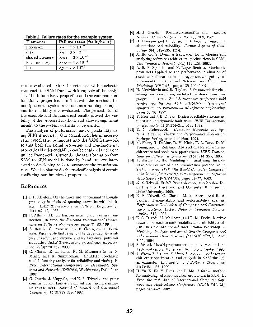
Table 2. Failure rates for the example system.áãâåäçæèäçéëê(ì íïîñðòâòóÕôõäöôõî÷êÚäøìúùÄûüîýóþâ¢êõÿ���� óïô��Ð,Ë`Æy×�Ì.Å4Å�ÆNË ® ö Aÿ���èJé��ÖyÒÕÅ`Ï ® � Aà÷���èJé� "Å�Ü�ÊjË`ÌJÖ�Î�Ì.ÎEÆNË`Í ®@�/þ Aàú���èJé� ÉÙrÆy×�ÊjÙTÎ�Ì�Î�ÆjË4Í ®7ý�þ Aàú���èJé� Éß,Ý�Å ® � A ó��Sè.é�� È
×�Ê�Ó³ßWÌEÌ�Þ=Ê�ÙÕÝ�Ê�È`Ì.ÖìáDÄ�Ç�È`Ì.Ë�È4Ü,ÌEÌ�ÚfÈ`Ì.Ó�Å�ÒÕÆjÓ³ÉAÒpÈ4Ü�Å�È`Æy×�Ü�ÊjÅ�È`Ò«××�ÆjÓWÅ�È4Ë`Ý�×�È.ÛjÈ`Ü,Ì�ð,Ĩë ÇË�Ê�Î�Ì�ÉqÆjË4Ï�Ò«Ål×.Ê�Ð�Êjß,ÙrÌAÆjÇ@È`Ü,ÌPÊ�Ó�ÊjÙrÍLØÅ�Ò«ÅlÆjÇìßWÆjÈ`Ü�ÇÝ,Ó�×�È4ÒrÆNÓ�Ê�Ù@Ð,Ë4ÆjÐ�Ì�Ë`È`ÒÕÌ.ÅqÊ�ÓWÖ�È`Ü,ÌD×�ÆNÎ�ÎEÆNÓ�Ó,ÆNÓyØÇÝ,Ó�×�È4ÒrÆNÓ�Ê�Ù�Ð,Ë4ÆjÐ�Ì�Ë`È`ÒÕÌ.Å.á û>Æ_ÒrÙÕÙrÝWÅ�È4Ë4Ê�È`ÌÈ4Ü,̳Î�Ì�È4Ü,ÆyÖTÛAÈ4Ü,ÌÎ�Ý,ÙrÈ`ÒÕÐ,Ë4Æf×�Ì.Å4Å�ÆNË^Å`ÍyÅ�È4Ì�ÎöÉÁÊjŤÝWÅ�ÌJÖ�ÊjÅÁÊ�Ë`Ý,Ó�Ó,ÒrÓ�Ñ¥Ì�ÚyÊjÎ�Ð,ÙrÌNÛÊ�Ó�Ö�ÒpÈ�ÅDË`Ì.ÙrÒ«Ê�ß�ÒrÙÕÒpÈ�ͳÉqÊNÅDÌ�Þ=Ê�ÙÕÝ�Ê=È4Ì.ÖTá'ûÁÜ,Ì�Ð,Ë4Ì.Å`Ì�ÓLÈ�Ê=È`ÒÕÆjÓ�Æ�ÇÈ`Ü,ÌEÌ�Ú,Ê�Î�Ð,ÙÕÌ�Ê�Ó�Ö³ÒpÈ�ÅDÓLÝ�ÎEÌ.Ë`Ò«×�ÊjÙ2Ë4Ì.Å`Ý,ÙrÈ4ÅPÐ,Ë4Æ=ÞjÌJÖ�È`Ü,ÌEÞfÒÕÊ�Øß,ÒrÙÕÒrÈ�Í"ÆjÇ�È4Ü,Ì�Ð�Ë`ÆNÐWÆLÅ�ÌJÖ"Î�Ì�È`Ü,ÆyÖTÛ@Ê�Ó�ÖÊjÙrÙÕÆ=ÉqÌ.Ö�Å�ÒÕÑjÓ�ÒpüW×.Ê�ÓLÈÒrÓ�Å`ÒÕÑjÜLÈÁÈ`ÆEÈ`Ü,Ì�Å`ÍyÅ�È4Ì�ΩïNÝWÊ�ÙÕÒpÈ4ÒrÌJÅqÈ`Æ�ßWÌâÑLÊ�ÒÕÓ,Ì.ÖìáûÁÜ�Ì�Ê�Ó�ÊjÙrÍyÅ`ÒÕÅPÆ�ÇqÐWÌ.Ë�ÇÆNË`Î'ÊjÓ�×�Ì'Ê�ÓWÖ�ÖyÌ.ÐWÌ.Ó�Ö,Êjß,ÒrÙÕÒrÈ�ͳÝ�Å�Ø
ÒrÓ,Ñ�ð ��Å^Ò«ÅqÓ,Æ�ÈÁÓ,Ì.Éâá� �Ý�Ëq×�ÆjÓLÈ`Ë4Òrß�ÝyÈ`ÒÕÆjÓ�ÙÕÒÕÌ.ÅqÒrÓ"ÒrÓW×�ÆjË4Ð�Æ�ØË4Ê�È`ÒÕÓ,ѯÅ�È`Æy×�Ü�ÊNÅ�È4ÒÕ×¥È4Ì.×�Ü,Ó,Ò«ïLÝ,Ì.ÅDÒÕÓLÈ`ƯÈ`Ü�Ì�ðyĨë ÇË�Ê�Î�Ì�ÉqÆjË4ÏÅ�Æ"È`Ü�Ê�ÈâßWÆjÈ`Ü�ÇÝ,Ó�×�È4ÒrÆNÓ�Ê�ÙVÐ�Ë`ÆNÐWÌ.Ë�È4ÒrÌJÅPÊjÓ�Ö�Ó,ÆjÓyØQÇÝ,Ó�×�È`ÒÕÆjÓ�ÊjÙÐ,Ë`ÆNÐWÌ.Ë�È4ÒrÌJÅ@ÙrÒÕÏjÌ^ÖyÌ�Ð�Ì�Ó�Ö�Ê�ß,ÒÕÙrÒrÈ�ÍD×�Ê�ÓDß�ÌlÊ�ÓWÊ�ÙÕÍLÔ.Ì.ÖPÝ,Ó�Ö,Ì�Ë>ÆNÓ,ÌÝ,Ó,Òrü�Ì.ÖEÇË�Ê�Î�Ì�ÉqÆjË4Ï@á�ù^Ý,Ë4Ë`Ì.ÓLÈ`ÙÕÍjÛ�È4Ü,ÌAÈ4Ë4ÊjÓ�Å�ÇÆNË`Î'Ê�È`ÒÕÆjÓ¥ÇË`ÆNÎðyĨë È4Æ:ð �$Î�ÆyÖyÌ�ÙPÒÕůÖyÆNÓ,̳ßfÍuÜ�Ê�ÓWÖTÛ�Éq̳Ê�Ë4Ì�ÒÕÓNÈ4Ì�Ë`ØÌ.Å�È`Ì.Ö�ÒÕÓ�ÖyÌ.ÞjÌ�ÙÕÆjÐ�ÒrÓ,Ñ�È4ÆfÆjÙ«ÅAÈ`Æ"Ê�ÝyÈ4ÆjÎ'Ê=È4ÌâÈ`Ü,Ì�È`Ë�Ê�Ó�Å�ÇÆjË4Î'Ê=ØÈ`ÒÕÆjÓìá�ò�ÌAÊjÙÕÅ`Æ�Ð�ÙÕÊjÓ�È4ÆDÖ,Æ�È4Ü,ÌÁÈ`Ë�ÊjÖ,Ì�Æ�î�ÊjÓ�Ê�ÙÕÍyÅ�Ò«Å�Æ�Ç�×�Ì�Ë`È4ÊjÒrÓ×�ÆjÓ#�ÒÕ×�È`ÒÕÓ,Ñ�Ó,ÆjÓ,ØMÇÝ,ÓW×�È`ÒÕÆjÓWÊ�ÙTÐ,Ë4ÆjÐ�Ì�Ë`È`ÒÕÌ.Å.á
Öû� � � x �>¾ { � v
������� Ì��bÌ�� Æ:Ô ÄÈë í Ä���Ì��)Ç ËVß«ÁbÁ�� é ÀIË é Ç í é ð©ð«¾V¿�� Ä Ó é ËVÁ»ËVß«¾V¿�Ú É ß� ð«Ú«Ë é Ç é ë Ô±Â Ä Âu¿ è À ë ¿�Â�Á¯í"!:Ú©Á3Ú ÄkÇ©É�Ç ÁIËDÅm¿�¾VÆÝÂóÅ Ä ËVßRä ë ¿:ÀGÆ# ÄkÇ«É«Ì%$'&(&)&+*-,/.�0-12.43�57698�0�1:8�0<;8'=>57?�.�,A@B&C0ED�6F0�@A@2,26F0ED#G�H��I-J'��K2L MON�PEQ�R H �TSOU�U Ì
� NV��W ÌV��ëÈë Á Ç é Ç íEÎ Ì�X é ¾ ë é Ç7Ì4� ¿�¾VÓ é ëkÄ��IÄÈÇ«É é ¾VÀ<ß Ä ËVÁ3ÀIËVÚ«¾ é ë À3¿ Ç Ç Á3ÀIË Ä ¿ Ç�Ì � ÇZYC,/8�3VG)5F[-@\;-6^]�5_@>@20�5F[`$>0-5_@2,>0.�57698�0.Oa�b(8�0�=T@2,�c@20d3>@\8�0`;8'=>57?�.�,A@e&C0ED�6F0�@A@2,26F0ED�H ð é É Á3 Q#�2P#UOR H ��SOS�I Ì
� f�� �-Ì Ùb¿�ä©ä Ä ¿ H�X.Ì� ¾ é Ç À3Á3Â�ÀGß ÄkÇ©Ä Â H W ÌX é ÁIË é H é Ç í î Ì ½5¿�¾�Ë Ä Ç é ë Á Ì ½ é ¾ é Ó'ÁIË�¾ Ä À èêé Ú ë Ë/Ë�¾VÁ3Á è ¿�¾bËVß«Á)í±Á3ð�Á Ç í é ä ÄkëÈÄ ËDÔ é Ç é ë Ô±Â Ä Â)¿ è ¾VÁ¯í«Ú Ç í é Ç ËS Ա ËVÁ3Ó' é Ç í Ä ËVÂ)ß ÄkÉ ß� ë ÁTg9Á ë ð�ÁIË�¾ Ä5Ç Á<ËÂ�ÁIÓ é Ç Ë Ä À3 Ìh$'&(&)&i*�,/.�0�1�.O3�57698�0-1j8�0`;d8'=257?).�,A@k&C0ED�6F0�@A@2,�c6F0ED�H N�S�J9fOK2L NOQ�R�P�N�U4Q H N�ROROf Ì
� I�� X.ÌmlbÄ é ¾Gí«¿ H W Ì î Ì�n ¿ Ç Á3 H W Ì�o�Ìmo é ¾VÓ'¿�¾V ËVÁ ÄkÇpHk� Ì�ãÌo ÄkÇ ÁI¾ H é Ç í W Ì ã±Ä Ó ÄkÇ©Ä À3Á é Ç Ú Ì ã-o�� W Þ L ã ËV¿:ÀGß é Â Ë Ä ÀÓ'¿Ýí±Á ë ,À<ß«Á3À<Æ ÄkÇ©É é Ç é ë Ô � ÁI¾ è ¿�¾�¾VÁ ëÈÄ é ä ÄkëkÄ ËDÔ é Ç íuË Ä Ó ÄkÇ©É±Ì � ÇYC,/8�3VG�$>0-5_@2,>0.�57698�0.Oa�b(8�0T=�@2,A@20d3>@"8�0rqs@_t�@20u4.OvTa�@:;-w�12c5_@2xj1C.�0u�yz@257?)8�,A{�1h|}qk;Ey�~ �V����H�� é Â�ß ÄÈÇ«É ËV¿ Ç�H Î Ì lSÌ^H�n Ú Ç Á�TSOSON Ì
� �V� X.Ì�lbÄ é ¾Gí«¿ H�n«Ìpo Ú«ð©ð é ë é H é Ç í�� Ì"ãÌ Þ�¾ Ä gKÁ¯í ÄìÌ���Ç é ë Ô �3ÄkÇ©ÉÀI¿ Ç ÀIÚ«¾�¾VÁ Ç Ë é Ç í èìé Ú ë Ë/ ËV¿ ë ÁI¾ é Ç Ë Â�¿ è Ë>Å é ¾VÁuÚ©Â ÄkÇ©É Â ËV¿:À<ß é Â' Ë Ä Àu¾VÁIÅ é ¾Gí Ç ÁIËV Ì��E8��E,>0.Oah8'=\Yh.�,'.Oa}a�@�a�.�0u�qk6F1>57,>69v��E5_@/ub(8�xetd�E576}0#D�H �V�EJ9f4K2L NO����PEN�MOS H ��SOSON Ì
� MV��� Ì�n«ÌsX Á Ç ¾ Ä À<ß Ì ½»¾VÁ¯í Ä À é ËVÁ Ê Ë�¾ é Ç Â Ä Ë Ä ¿ Ç Ç ÁIËV Ì%��@/3�57�E,A@yk8�5_@21�6}0�b(8�xmtd�E5_@2,z;3�6�@20d32@2H NO�VI�L NO����P�N�MOS H �TSOUOQ Ì
� Q���� Ì � é Ç Â�Â�¿ Ç é Ç í�Ù Ìhn ¿ Ç Â�Â�¿ Ç�Ì�� ë ¿ É�Ä À è ¿�¾(¾VÁ é Â�¿ Ç©ÄkÇ©Éé ä�¿�Ú«Ë.Ë Ä Ó'Á é Ç í�¾VÁ ëÈÄ é ä ÄkëkÄ ËDÔ Ì:��8�,>x�.Oa��e19t�@A3�571�8'=�b(8�x�ctd�E576}0#D�H M�J7I#K2L �E��N�P���f4� H �TSOS�I Ì
� UV��� Ì � Á é Ç í�� Ì ÎEÁ Ç©É«ÌC� è ¾ é Ó'ÁIÅm¿�¾VÆ è ¿�¾Eí±ÁTg9Á ë ¿�ð ÄkÇ©É é Ç íé Ç é ë Ô �3ÄkÇ©É Â�¿ è Ë>Å é ¾VÁ é ¾VÀGß Ä ËVÁ3ÀIËVÚ±¾VÁ�Â�ð�Á3À Ä�� À é Ë Ä ¿ Ç Â ÄkÇuã��eo�Ì*�[-@�b(8�xet-��5_@2,s�E8��E,>0.Oa H I#�EJ'�VK2L^�O���2Pd��N�U H N�RORON Ì
� SV� � Ì W Ì�o À ã ð é í©í«Á Ç é Ç í�� Ì î ¿Kð�Á � DÙbÁ Ç©Ä ËVÁ ��Ì�ã ËV¿:ÀGß é Â Ë Ä Àð�ÁIË�¾ ÄSÇ ÁIËV é ð©ð ëkÄ Á3í�ËV¿�ËVß«Á�ð�Á<¾ è ¿�¾VÓ é Ç À3Á�ÁTg é ë Ú é Ë Ä ¿ Ç ¿ èÂ Ë é Ë Ä À!Ë é Â�Æ é ëkë ¿:À é Ë Ä ¿ Ç Â ÄkÇ ß«ÁIËVÁI¾V¿ É Á Ç Á3¿KÚ«ÂbÀ3¿�Ó'ð©Ú«Ë ÄkÇ«É Á Ç g Ä ¾V¿ Ç Ó'Á Ç ËVÂ Ì � Ç�YC,/8�3VGs��5F[:�s@25_@2,'8AD#@20�@/8��E1:b(8�xetd�E576}0#D��8�,A{�1'[�8>t:|}��Ykbz~ #¡>��H ð é É Á3 �TU4��P-��S�I H ��S�S4Q Ì
����RV� � Ì�o Á¯í�g Ä í«¿Vg Ä À é Ç í W Ì Þ é Ô ë ¿�¾ Ìj� è ¾ é Ó'ÁIÅm¿�¾VÆ è ¿�¾-À ë é Â' Â Ä è Ô ÄkÇ©É é Ç í À3¿KÓ'ð é ¾ ÄkÇ©É é ¾VÀ<ß Ä ËVÁ3ÀIËVÚ«¾VÁ&í«ÁIÂ�ÀI¾ Ä ð«Ë Ä ¿ Ç÷ë é Ç É Ú é É Á3Â Ì � Ç¢YC,/8�3VGj5F[-@£��5F["&C�E,/82t�@/.�0¤3A8�0T=�@2,A@20d3>@B[-@�a^u¥ 8�6F0-59a w<?¦6}5F[�5F[�@¢§�5F[¨�sb�©ª;E$�«C;�¬¦�e*6}0�5_@2,20d.�57698�0d.Oa1Aw�xmt�8�1A6}�Ex®8�0���8��E0u4.�57678�0-1�8'=B128'=257?).�,A@¯@20ED�6F0�@A@2,26F0ED�Hð é É Á3 M�RVP�Q�M H �TSOSOQ Ì
���O�2� � Ì W Á Ç é Ç í n±Ì Ù Ì ÎEÚ É é Ç7Ì Î)Á3 ÄkÉKÇ ¿ è ¾VÁ ëÈÄ é ä ë Á! Ա ËVÁ3Ó'ÂJÚ«Â' ÄkÇ©É Â Ë é Ë Ä À é Ç íóíÝÔ Ç é Ó Ä À èìé Ú ë Ë/Ë�¾VÁ3ÁI Ìp$'&(&)&°*-,'.�0-12.43�57678�0-18�0�±�@�a 69.4v�67a 6F57w�H I#QEJ9f4K2L N�f�I�P�NVIOI H�o é Ô ��S�SOU Ì
���VN�� Þ Ì�X.Ì W ¿Kä�Á<¾�Ë é �T�3ÄìÌ b(8�xmtd�E5_@2,²yz@257?�8�,A{�1¢.�0u³;�w�1>c5_@2x\1�´BµC�-@2�E6}0ED£*�[-@/8�,>w�.�0du�Yh@2,}=�8�,2x�.�03>@�&C¶�.Oa ��.�57698�0©Ìã ð±¾ ÄkÇ©É Á<¾/ _·@ÁI¾ ë é É�H Â�Á3À3¿ Ç í Á¯í Ä Ë Ä ¿ Ç�H �TSOS�I Ì
����fV� o�Ì7ã ß é Å H W Ì ÎEÁ î ÄkÇ Á H Î Ì · Ì � ë Á ÄkÇ�H Þ Ì î Ì W ¿�Â� H Î Ì�o�Ì�/¿KÚ Ç«É�H é Ç í X.Ìd¸ Á ë Á3Â Ç«Ä Æ Ì�� ä©Â Ë�¾ é ÀIË Ä ¿ Ç Â è ¿�¾�Â�¿ è ËDÅ é ¾VÁ é ¾/ ÀGß Ä ËVÁ3ÀIËVÚ±¾VÁ é Ç íuËV¿:¿ ë Â�ËV¿aÂ�Ú«ð©ð�¿�¾�Ë!ËVß©Á3Ó Ì¦$'&)&(&³*-,'.�0-12.43Tc57698�0�1z8�0�;d8'=257?).�,A@e&�0#D�6}0�@A@2,>6}0ED�H NE�4J7I4K2L f��TIVPEfO�O� H �TSOS4� Ì
���TI�� Þ Ì5ã ß Ä é Ç í � Ì � Á ̹o ¿Ýí±Á ëkÄÈÇ«É é Ç í é Ç é ë Ô �3ÄkÇ©É ËVß«ÁóÂ�¿ è Ë/ Å é ¾VÁ é ¾VÀGß Ä ËVÁ3ÀIËVÚ±¾VÁó¿ è�é À3¿KÓ'Ó.Ú Ç«Ä À é Ë Ä ¿ Ç ð«¾V¿�ËV¿:ÀI¿ ë Ú©Â ÄkÇ©Éã��eo�Ì � ǺY�,'8�3VG$'�¦$'Y�»#¡V5F[���8�,2a^u¼b(8�xetd�E5_@2,sb(8�0ED�,/@21>1mc*Cb��k;-57,/@/.�x�½�¾O,/um$'&(&)&�½�$'�¦$'Y¿b(8�0�=�@2,/@203>@m8�0\;8'=257?).�,/@�h,/3>[#6}5_@/3�57��,/@¹|V�º$�b�;E��~ �V����H ð é É ÁI M�fVPEQOQ H N�RORON Ì
���V��� � Ì©ãÌ Þ7¾ Ä g9Á¯í ÄìÌ�;EY)yhYÁÀp1�@2,-~ 1h©Z.�0-�-@�a ¦¶�@2,>1>678�0B�4G}��Ì ÎEÁ2 ð é ¾�ËVÓ'Á Ç Ë ¿ è¼Ã ë Á3ÀIË�¾V¿ Ç«Ä À é Ç í l ¿�Ó'ð©Ú«ËVÁ<¾ à ǩÉ�ÄkÇ Á3ÁI¾ ÄkÇ«É�HÎEÚ«Æ9ÁeÄ Ç©Ä g9ÁI¾VÂ Ä Ë>Ô H �TSOSOS Ì
����MV� � ÌSãÌ Þ�¾ Ä gKÁ¯í Ä7HsX.ÌmlbÄ é ¾Gí±¿ H\o�Ìmo é ë ß«¿�Ë�¾ é H é Ç í W Ìh�-Ìã é ß Ç ÁI¾ Ì ÎEÁ3ð�Á Ç í é ä ÄkëkÄ Ë>Ô é Ç í�ð�ÁI¾ è ¿�¾VÓ é ä ÄÈëkÄ Ë>Ô é Ç é ë Ô±Â Ä Â ÌYh@2,}=T8�,2x�.�03>@k&C¶�.Oa ��.�57698�0�8'=ºb(8�xetd�E5_@2,\.�0uZb(8�x\x\�E0�67c3A.�57698�0:;-w�1A5_@2x\1AÂk��@A3�57�E,/@�yk8�5_@21�6F0²b(8�xmtd�E5_@2,�;d3�6�@203>@2HQON�S�L ��UOQ�P#M��VN H ��SOS�f Ì
���VQ�� � ÌÝã�Ì Þ7¾ Ä g9Á3í Ä7H�o�ÌEo é ë ß©¿�Ë�¾ é H é Ç í W Ì4o�ÌE� ¾ Ä À<ÆÝ Ì�o é ¾VÆ9¿Vg¾VÁIÅ é ¾Gí é ð«ð«¾V¿ é À<ßWËV¿�ð�ÁI¾ è ¿�¾VÓ é ä ÄkëÈÄ ËDÔ é Ç íW¾VÁ ëÈÄ é ä ÄkëkÄ ËDÔ é Ç é ë Ô±Â Ä Â Ì � Ç�YC,/8�3VG�5F[-@�;�@/3A8�0du�$>0�5_@2,20d.�57698�0d.Oaz��8�,/{�1'[�82t:8�0©Z8�u#@�a 6F0ED�Âd�h0.Oa w�1A6}1AÂ�.�0uk;-6}xj��a^.�57698�0�¬C0�b(8�xmtd�E5_@2,h.�0u*�@�a�@/3A8�x\xj�E0-693A.�57698�0¨;-w�1A5_@2x\1�|7©���;�b�¬k*�;C~ �ÅO��H ð é É ÁIÂQ�P-�O� H ��S�S�I Ì
����UV� ãÌ ·@Á3Â Ë é ë ̦o ÁIË é � ð«¾V¿ É ¾ é Ó'Ó'ÁI¾�Æ ÂmÓ é Ç Ú é ë7H g9ÁI¾VÂ Ä ¿ Ç � Ì R�S ÌÞJÁ3ÀGß Ç«Ä À é ë ¾VÁ3ð�¿�¾�Ë H � ¿ Ç Á<Ô±ÅbÁ ëkë ÞJÁ3ÀGß Ç ¿ ë ¿ É Ô l Á Ç ËVÁI¾ H �TSOS�M Ì
����SV� n«Ì�� é Ç©É�H � Ì � Á H é Ç í�� Ì ÎEÁ Ç©É±Ì � Ç Ë�¾V¿Ýí±Ú©À ÄkÇ©É Â�¿ è Ë>Å é ¾VÁ é ¾/ ÀGß Ä ËVÁ3ÀIËVÚ±¾VÁ.Â�ð�Á3À Ä^� À é Ë Ä ¿ Ç é Ç í é Ç é ë Ô±Â Ä Â ÄÈÇ�ã���o ËVß±¾V¿KÚ É ßé Ç Á�� é Ó'ð ë Á Ì�$>0�=T8�,>x�.�57698�0°.�0u£;8'=257?).�,/@"*�@/3>[E08Oa^8AD�w�HI��OJ�QOK2L I#�#�2P4I4M4Q H ��S�SOS Ì
� N�RV��� Ì �/Ú H � Ì � Á H � Ì ÎEÁ Ç©É�H é Ç í î Ìdo ¿ Ì)� è ¿�¾VÓ é ë Ó'ÁIËVß«¿Ýíè ¿�¾ é Ç é ë Ô �3ÄkÇ«É Â�¿ è ËDÅ é ¾VÁ é ¾VÀ<ß Ä ËVÁIÀIËVÚ«¾VÁ!Ó'¿Ýí±Á ë  ÄkÇ�ã���o�Ì � ÇYC,/8�3VGh5F[-@�����5F[��h0�0-��.Oa�$>0-5_@2,>0.�57698�0.�azb(8�xetd�E5_@2,�;d8'=259c?).�,A@£.�0du"��t4ta 693A.�57678�0-1"b(8�0�=�@2,/@203>@¿|Ab�¬)©�YC;��sbz~ ������Hð é É Á3 M�I#��P#M4��N H N�R�R4N Ì
Formalizing Dependability Mechanisms in B:From Specification to Development Support
F. Tartanoglu, V. IssarnyINRIA Rocquencourt
N. LevyLaboratoire PRISM
Universite de VersaillesSaint-Quentin, [email protected]
A. RomanovskySchool of Computing Science
University of Newcastle upon TyneUK
Abstract
The CA action concept has been proven successful forbuilding dependable distributed systems due to its supportfor error recovery for both competitive and cooperativeconcurrent actions. This paper introduces the formal speci-fication of dependability mechanisms offered by CA actionsusing the B formal method, from which an XML-based lan-guage is derived. The resulting language then allows devel-oping dependable systems, where the B formal specificationis refined to obtain an implementation of the associated run-time support.
1. Introduction
Dependability of systems is defined by the reliance thatcan be put on the service they deliver. Developing dis-tributed systems that are dependable is recognized as a com-plex task, requiring adequate mechanisms for dealing withthe occurrence of failures. Coordinated Atomic Actions(CA actions) [8] provide a general structuring mechanismfor developing dependable systems through the exploitationof atomic actions and transactions. The composition of CAactions [6] further extends the base CA action model fordeveloping open distributed systems.
Several applications have proven that CA actions are ef-fective for building dependable concurrent systems [9, 2].Formalization of applications based on CA actions, us-ing Petri nets and temporal logic, further enables to provethe applications’ dependability properties through model-checking [7, 5]. However, dependability properties areproved with respect to a specific application.
Our approach aims at providing a language for devel-oping distributed systems using dependability mechanismsthat are formally specified and implemented. Towards that
goal, we provide a formal specification of the dependabilitymechanisms associated with the CA action concept usingthe B formal method, from which we derive an XML-basedlanguage to be used to develop dependable applications.
The paper is structured as follows. Section 2 brieflypresents CA actions and their composition. Sections 3 and 4then introduce the B formal specification of CA actions,discussing in particular the specification of dependabilitymechanisms offered by CA actions. Definition of the result-ing XML-based development support follows in Section 5.Finally, Section 6 concludes, summarizing our contributionand discussing areas for future work.
2. Architecting Dependable Systems with Co-ordinated Atomic Actions
CA ActionsThe CA actions [8] are a structuring mechanism for de-
veloping dependable concurrent systems through the gen-eralization of the concepts of atomic actions [3] and trans-actions [4]. Atomic actions are used for controlling coop-erative concurrency among a set of participating processesand for realizing coordinated forward error recovery usingexception handling; transactions are used for maintainingthe coherency of shared external resources that are compet-itively accessed by concurrent actions. Each CA action isdesigned as a multi-entry unit with roles activated by actionparticipants, which cooperate within the action. A transac-tion is started upon each first access to a given external ob-ject by a CA action participant and it terminates at the endof the CA action. A CA action terminates with a normaloutcome if no exception has been raised or if an exceptionhas been raised and handled successfully; all transactions onexternal objects are then committed. If a participant raisesan exception inside an action and if the exception cannot behandled locally by the participant, the exception is propa-

gated to all the other participants of the CA action for co-ordinated error recovery1. If coordinated recovery fails, theCA action terminates with an exceptional outcome. An ex-ception is then signalled by the CA action and transactionson external objects are aborted.
CA actions can be designed in a recursive way using ac-tion nesting. Several participants of a CA action can enterinto a nested CA action, which defines an atomic opera-tion inside the embedding CA action. Accesses to exter-nal objects within a nested action are performed as nestedtransactions so that if the embedding CA action terminatesexceptionally, all sub-transactions that were committed bynested actions are aborted as well. A CA action participantcan only enter one nested action at a time. Furthermore, aCA action terminates only when all its nested actions havecompleted. Note that if the nested action terminates excep-tionally, an exception is signalled to the containing CA ac-tion.
As an illustration, Figure 1 depicts a CA action A1 thatis entered by participants P1-P3 and that comprises twonested CA actions, A11 and A12; transaction are further ex-ecuted on external objects. An exception raised by partici-pant P2 causes the CA action to enter an exceptional state,as showned by the greyed box, where the participants coop-erate for handling the exception.
P1
P2
P3
A11
A12
Transactions
Coordinated ExceptionHandling
A1
exception
Figure 1. Coordinated atomic actions
CA actions mainly focus on structuring concurrentsystems and on providing their fault tolerance by exceptionhandling. One of the main intentions behind CA actions isto employ them as the mechanism for structuring complexdistributed applications: they promote recursive view onsystem execution with abstracting away both normal andabnormal behaviour of the low level software.
CA Actions CompositionComposing CA actions allows the design of open dis-
tributed systems built out of several CA actions. Unlikeclassical action nesting where a subset of action participants
1If several exceptions have been raised concurrently they are resolvedusing a resolution tree imposing a partial order on all action exceptions,and the participants handle the resolved exception [3].
enters into a nested action, composed CA actions are au-tonomous entities with their own participants and externalobjects. In this model, a participant of a CA action can dy-namically initiate the creation of a composed CA action (ordynamically nested action).
The internal structure of a composed CA action (i.e., setof participants, accessed external objects and participants’behavior) is hidden from the calling CA action, which onlyhas an access to the composed CA action’s interface. A par-ticipant that calls a composed CA action enters a waitingstate in a way similar to a synchronous RPC. The partici-pant then resumes its execution according to the outcomeof the composed CA action. If the composed CA actionterminates exceptionally, its calling participant raises an in-ternal exception which is possibly locally handled. If localhandling is not possible, the exception is propagated to allthe peer participants for coordinated error recovery. Notethat unlike static nesting, when a composed CA action hasterminated with a normal outcome, an abort operation ofthe containing CA action does not automatically compen-sate effects of the composed one; specific handling must beperformed at a higher level, e.g., a composed action can beinitiated to abort/compensate actions on external objects ifneeded.
Figure 2 illustrates the use of nested and composed CAactions, considering a travel agency system. The top-levelCA action comprises the User and the Travel participants;the former interacts with the user while the latter achievesjoint booking according to the user’s request. The CA ac-tion has further access to the Banking System. In a first step,the User participant requests the Travel participant to searchfor a trip. This leads the participants to enter the nestedaction SearchTrip in which the Travel participant invokes acomposed action comprising the Hotel and the Flight partic-ipants. The external objects accessed by those participantsare the hotel and flight booking system. The SearchTrip ac-tion, if successful, returns a list of possible trips. Then, ac-cording to the User’s selection, the BookTrip nested actionis executed, where another composed CA action is initiatedto book the given trip. If an exception is raised within thecomposed CA action (e.g., no flight available for a givendestination) and if it cannot be handled internally, the com-posed action terminates exceptionally by aborting all trans-actions on external objects and signals a failure exceptionto the higher level.
3 Specifying CA Actions in B
The B methodB is a complete formal method [1] that supports a large
part of the development life cycle, from abstract specifica-tion to implementation. The B formal method is a model-based method, which is based on set theory and predicate

SearchTrip
Flight BookingSystem
SystemHotel Booking
BookTrip
exceptional
waiting
normalparticipants:
recoverycoordinated
BankingSystem
TravelAgency
User
Travel
Hotel
Flight
Hotel
Flight
exception
Figure 2. CA actions composition
logic and extended by generalized substitutions. B specifi-cations are represented by abstract machines encapsulatingoperations and states. Generally speaking, the B method al-lows us to define abstract machines and refinements overthem. During the refinement nondeterminism is reducedand preconditions are relaxed, but the interfaces of the op-erations remain the same. At the end of the refinement pro-cess, an implementation can be written, which correspondsto an executable code.
Proofs are an essential part of the model: it should beproven that all operations preserve the invariants of themachine, and that the implementations and refinementspreserve the invariants and the behaviour of the initialabstract machine. There are various tools that help writingand proving B specifications. The main of them areB-Tool2 and Atelier B3. Both tools include a type checker,an animator, a proof obligation generator, theorem provers,code translators and documentation facilities. Atelier B hasbeen used in our investigation, however the notation weused is compatible with B-Tool.
Modelling CA ActionsOur goal in providing the B specification of CA actions
is to offer a general framework that can be instantiated todescribe the implementation of a specific system that is de-veloped using CA actions. The framework thus defines thedependability properties associated with CA actions, whichwill be enforced for any system based on them.
The B formal specification of CA actions is given by theCAACTIONS abstract machine. The machine extends ma-chines OBJECTS and PARTICIPANTS, which respectivelydescribe external objects that can be accessed or modifiedby a CA action, and the participants of a CA action (seeFigure 3). The CONST machine further contains globaldeclarations and is seen by all the other machines. In the
2http://www.b-core.com/btool.html3http://www.atelierb.societe.com
remainder, we introduce the main elements of the B specifi-cation, focusing on dependability properties associated withCA actions; the interested reader may find the overall speci-fication at http://www-rocq.inria.fr/˜tartanog/dsos/.
CONST
OBJECTS PARTICIPANTS
CAACTIONS SEESEXTENDS
Figure 3. Structure of the B specification
The state of the PARTICIPANTS abstract machine char-acterizes the participants of a CA action as follows:
� The PARTICIPANT set is declared in the CONST ma-chine and represents all possible participants that canbe involved in a CA action.
� A participant that is activated by entering in a CA ac-tion is included in the subset participant of PARTICI-PANT and removed at the end of the action:
participant�
PARTICIPANT
� Each participant enters in a sequence of modes (re-ferred to as state), which can be normal, exceptionalwhen an exception has been raised, or waiting ifthe participant invokes a composed CA action and isblocked until the action’s termination:
participant state � PARTICIPANT �� seq(PARTICIPANT STATE)
� Each participant has a value (local variables) that islogged for later use in case of backward recovery:
participant value � PARTICIPANT �� VALUE �initial values � PARTICIPANT �� seq(VALUE)
The CAACTIONS abstract machine defines operationsassociated with the execution of CA actions: creation,termination, nesting and composition of CA actions,message exchange between participants, and exceptionhandling. An abstract set CAACTION of all possible CAactions is introduced together with subset caaction of theCA actions that are running at a given state of the system.Three types of CA actions are distinguished: the top-level,nested and composed CA actions; two variables are used tomemorize the nested and the composed CA actions:

is nested � caaction � caaction �is composed � participant �� caaction
The state of the CAACTIONS abstract machine is definedby the following attributes:
� CA actions have a mode (referred to as state) that canbe normal (if all the participants are in normal mode)or exceptional (if all the participants are in exceptionalmode).
CAACTION STATE = � caa normal, caa exceptional �caaction state � caaction � CAACTION STATE
� Each CA action has a set of participants and each ofthem participates to a sequence of nested CA actions:
participant of caaction � caaction � (participant)caaction of participant � participant � seq(caaction)
� CA actions access several external objects:
caaction ext objects � caaction � objects
Several invariant properties of the CA actions have beenidentified and specified. They are written as constraints onthe variables of the abstract machines. The state transforma-tions associated with the execution of CA actions are furtherdefined by the following preconditioned operations4:
� create � main,nested,composed � caaction: initiates a CA ac-tion, either top-level, nested or composed;
� � send,recv � message(participant,participant,message): sends orreceives a message from one participant to a peer par-ticipant;
� � read,write � object(participant,object, � function � ): reads,writes the value of an external object;
� raise exception(participant,exception),propagate exception(participant): raises, propagates an ex-ception;
� abort � main,nested,composed � : aborts a CA action, sendingan abort message to all its external objects;
� terminate � main,nested,composed � � normal,exceptional �(caaction): terminates a CA action, either in a normal orin an exceptional state.
Invariant properties and operations are specified in sucha way that properties of the dependability mechanisms as-sociated with CA actions are enforced.
4Braces are used to denote multiple distinct operations.
4 Dependability Properties
The dependability mechanisms embedded within CAactions fall into three categories: (i) transactional accessto external objects, (ii) atomicity of CA actions, and (iii)coordinated exception handling.
Transactions on External ObjectsAccess to external objects within CA actions are per-
formed according to classical nested transaction rules. Theoperation that creates a top-level CA action initiates thetransaction on external objects associated to the CA action:
add objects(obj) =PRE
obj�
OBJECT � obj � object = �THEN
values := values � � obj ��� begin �����object := object � obj
END;
Participants setpar of nested CA action caa1 canonly access subset setobj of external objects associ-ated to containing CA action caa2. This constraintis ensured with the following precondition of thecreate nested caaction(caa1,caa2,setpar,setobj) operation:
�obj.(obj � setobj � obj � caaction ext objects[ � caa2 � ])
Then, the operation initiates a nested transaction on theexternal object (add nested object(setobj)). When a (possiblynested) CA action terminates its execution normally(terminate caaction(caaction)), it commits transactions onexternal objects:
terminate transaction(caaction ext objects[ � caaction � ],commit)
On the other hand, if the CA action terminates excep-tionally or aborts, all the transactions that it initiated onexternal objects are aborted as well:
terminate transaction(caaction ext objects[ � caaction � ],abort)
Note that nested transactions are aborted recursively bythe underlying transactional support of external objects.
Atomicity of CA ActionsCooperation of participants is encapsulated inside
atomic computation units using nested or composed CA ac-tions.
The following invariant property states that participantsof nested CA action caa1 are also participants of containingaction caa2:

�(caa1, caa2).((caa1 � caaction � caa2 � caaction �
(caa1,caa2) � is nested )� participants of caaction(caa1)�
participants of caaction(caa2) )
In the case when a participant invokes a composed CAaction, participants setpar of the composed CA action mustnot be involved in any other CA action:
setpar � participant = �
Communication between participants p1 and p2 within aCA action is realized by message exchanges. Preconditionsof the send message operation set the rules of messageexchange that is only allowed between participants of thesame (possibly nested) CA action. The participants mustbe in the same state (normal or exceptional). Finally, aparticipant that is in a waiting state (i.e., waiting for acomposed CA action to terminate) cannot send or receive amessage:
caaction of participant(p1) = caaction of participant(p2) �last(participant state(p1)) �� waiting �last(participant state(p1)) = last(participant state(p2)) �
Rules of nesting and composition are further specifiedwith the following preconditions of the CA action ter-mination operation stating, that a CA action terminateswhen all embedded nested and composed CA actions haveterminated:
caaction �� ran(is nested) � caaction �� ran(is composed)
Furthermore, a participant can only enter one siblingnested CA action at a time, which means that all partici-pants in setpar willing to enter a nested CA action are inthe same containing CA action:
card(ran( � p, c � p � setpar � c � CAACTION �c= last(caaction of participant(p)) � )) = 1
Finally, the participants willing to enter a nested CAaction must all be in the same state, normal or exceptional:
card(ran( � p, state � p � setpar �state � PARTICIPANT STATE �state= last(participant state(p)) � )) = 1 ��
(p).(p � setpar � last(participant state(p)) �� waiting )
Coordinated Exception HandlingThe following invariant ensures that a CA action is set
to an exceptional state if all of its participants are in theexceptional state. Note that the participant can be in a
waiting state following a call to a composed CA action, inwhich case case the test is performed on the last state of theparticipant before the call:
�(caa). (caa � caaction � caaction state(caa)= caa exceptional
� � (p).(p � participant of caaction(caa)� ((last(participant state(p)) � EXCEPTIONAL STATE) �((last(participant state(pa)) = waiting �last(front(participant state(p))) � EXCEPTIONAL STATE)))))
Exception raising and propagation (to other participants)is realized by two operations defined in the CAACTIONSmachine. The raise exception operation requires that theparticipant and the CA action are in the normal state, andsets the participant’s state to exceptional:
raise exception (p, exception) =PRE
p � participant �exception � EXCEPTIONAL STATE �last(participant state(p)) = normal �caaction state(last(caaction of participant(p))) = caa normal
THENset participants state( � p � , exception)
END;
The propagate exception operation is then called topropagate the exception to all participants of the CA action.
If a CA action terminates in an exceptional state, alltransactions on external objects are aborted. If this CA ac-tion is a nested or composed one, then the participant inthe containing CA action raises an exception by calling theraise exception operation (i.e., the exception is signalled toa higher level).
5. From the B Specification to the DevelopmentSupport
In order to have an implementation of the CA action’srun-time support, the abstract machines are refined. At theend of the refinement process, we have a set of executablecodes that correspond to the implementation of the opera-tions defining the B machines, offered as a programming li-brary. Note that, when implementing the CA actions, someexisting libraries such as drivers for running transactions areused. For all these libraries, what is usually known is the in-terfaces of the offered methods. In order to be able to provethe correctness of the implementation it would be neces-sary: (i) to have in addition the formal specification of thebehavior of these methods and (ii), to prove that the refine-ments of the machines that use these methods are correct (inthe B sense). During the refinement, the nondeterminismwill be reduced (e.g., by introducing of message queues).

The preconditions have to be relaxed in order to take intoaccount all the possible cases.
We introduce an XML-based language derived from theB specification in order to provide to the developer, whichmay not necessarily have a B knowledge, a convenientdeclarative language for building CA action-based systems.
Each XML document defines a main CA action whichcontains composed and nested CA actions, where composedCA actions are defined in a distinct document. The externalobjects are also declared.
<caaction name="nmtoken"? ><composedActions> ?
<action name="qname" /> *</composedActions><nestedActions> ?
<nested name="nmtoken" /> *</nestedActions><external> ?
<object name="nmtoken" /> *</external>
Each participant is then declared within the CA action,defining its local variables, which correspond to values usedin the B specification (participant value), and its behaviourcomposed of a normal and an exceptional parts. A partici-pant executes this exceptional part when the CA action is inan exceptional state, which means that the exception raisedby a participant has been automatically propagated to all ofthem.
<participants><participant name="nmtoken"> +
<var><element name="nmtoken" type="qname" /> *
</var><behavior>
<normal>Statements *
</normal><exceptional handle="qname"> *
Statements *</exceptional>
</behavior></participant>
</participants>
The statements declared in the behaviour part of the par-ticipant’s definition describe a sequence of operations to beexecuted. Each operation corresponds to the implementa-tion of an operation of the CAACTIONS machine
Statements:<invoke action="qname" input="qname"?
output="qname"? />�create composed
<send rcpt="qname" input="qname" />�send message
<recv from="qname" output="qname" />�recv message
<call rcpt="qname" input="qname"?output="qname"? />���
read,write � object<assign element="qname" value="XPATH" />
�set value
<raise exception="qname" message="qname"? />�raise exception
<nest nestedaction="qname"><behavior><normal>
Statements *</normal><exceptional handle="qname"> *
Statements *</exceptional>
</behavior></nest>�
create nested
The above language enables the development of systemsusing CA actions. It hides the details of the dependabilitymechanisms such as automatic exception propagation, andmore generally the behavior of the operations described inthe B specification and that will be executed during runtime.Furthermore, it enables static analysis to be performed inorder to verify the structural properties of a given systemdescribed in the invariant of the specification.
6. Conclusion
This paper has presented both how to specify depend-ability mechanisms using the B formal method and a devel-opment support relying on an XML-based language and onthe refinement process of B.
We have considered the use of CA actions that have beenproved useful for building dependable systems. We havedefined a generic formal specification using the B method,defining systems composed of several CA actions that makeconcurrent accesses to external objects. B was chosen be-cause of its powerful theorem proving ability and becauseof availability of a number of mature tools. We have shownhow to specify the following dependability mechanisms ofCA actions: (i) constraints related to the atomic access toexternal transactional objects, (ii) encapsulation of compu-tations inside atomic action units ensured through actionnesting and composition and (iii), properties related to thebehaviour of the system in case of exception occurrences.
The XML-based language is to be used for describinga specific system instance such as a travel agency system,by giving the behavior of each participant. Refinement ofthe B specification is exploited for offering a correct imple-mentation of the language. This includes static analysis andrun-time support, whose correct implementation further de-pends on the one of third-party libraries.
Up to now several implementations of CA actions havebeen proposed and experimented with, but mainly on closedsystems [9, 2]. We are working on an implementation ofCA action-based systems to be defined as a compositionof Web services such as the travel agency. This kind ofsystems clearly needs new dependability properties (e.g.,

relaxed atomicity properties for accessing external objects).We intend to use this initial B specification to study suchproperties.
AcknowledgmentsThis research was partially supported by the European ISTDSoS (Dependable Systems of Systems) project (IST-1999-11585)5.
References
[1] J.-R. Abrial. The B-book: assigning programs to meanings.Cambridge University Press, 1996.
[2] D. Beder, A. Romanovsky, B. Randell, C. Snow, andR. Stroud. An Application of Fault Tolerance Patterns and Co-ordinated Atomic Actions to a Problem in Railway Schedul-ing. ACM, Operating Systems Review, 34(4):21–31, October2000.
[3] R. H. Campbell and B. Randell. Error recovery in asyn-chronous systems. IEEE Transactions on Software Engineer-ing, SE-12(8), 1986.
[4] J. Gray and A. Reuter. Transaction Processing: Concepts andTechniques. Morgan Kaufmann, 1993.
[5] D. Schwier, F. von Henke, J. Xu, R. Stroud, A. Romanovsky,and B. Randell. Formalization of the CA Action ConceptBased on Temporal Logic. Design for validation (deva) ba-sic esprit project. second year report. part 2, LAAS, France,1997.
[6] F. Tartanoglu, V. Issarny, N. Levy, and A. Romanovsky. De-pendability in the Web Service Architecture. In Proceedingsof the ICSE Workshop on Architecting Dependable Systems,Orlando, USA, May 2002.
[7] J. Vachon, N. Guelfi, and A. Romanovsky. Using COALAto Develop a Distributed Object-Based Application. In In the2nd Int. Symposium on Distributed Objects and applications(DAO’00), P. Drew, R. Meersman, Z. Tari, R. Zicari (Eds.),pages 195–208, Antverp, Belgium, 2000.
[8] J. Xu, B. Randell, A. Romanovsky, C. M. F. Rubira, R. J.Stroud, and Z. Wu. Fault tolerance in concurrent object-oriented software through coordinated error recovery. In Pro-ceedings of the Twenty-Fifth IEEE International Symposiumon Fault-Tolerant Computing, 1995.
[9] J. Xu, B. Randell, A. B. Romanovsky, R. J. Stroud, A. F.Zorzo, E. Canver, and F. W. von Henke. Rigorous Devel-opment of a Safety-Critical System Based on CoordinatedAtomic Actions. In Symposium on Fault-Tolerant Comput-ing, pages 68–75, 1999.
5http://www.newcastle.research.ec.org/dsos/

Layered Dependability Modeling of an Air Traffic Control System
Olivia Das, C. Murray WoodsideDept. of Systems and Computer Engineering, Carleton University, Ottawa, Canada
email: [email protected], [email protected]
Abstract
Quality attributes, such as performance and depend-ability of a software-intensive system are constrainedby its software architecture. The combined performanceand dependability (called performability) effects of anarchitecture can be evaluated by constructing a per-formability model that considers the failure/repairbehavior and performance attributes of its components,interactions among the components and the fault toler-ant approaches adopted. This paper constructs andanalyzes a Dependable Layered Queueing Network(Dependable-LQN) performability model for a large-scale Air Traffic Control system. It demonstrates thecapability of the appraoch, for evaluating the perform-ability of a large-scale software architecture.
1. Introduction
The Dependable Layered Queueing Network(Dependable-LQN) model is a performability modelfor fault-tolerant distributed applications with a layeredsoftware architecture and a separate architecture forfailure detection and reconfiguration. It considers thefailures (repairs) of its application and managementcomponents, management connections and theapplication’s layered failure dependencies togetherwith the application performance. It combines Fault-Tolerant Layered Queueing Networks (FTLQN) andthe Model for Availability Management Architecture(MAMA) [1]. FTLQN in turn extends the LayeredQueueing Network model [2] (a pure performancemodel) with dependability related components andattributes. This paper describes its application to an AirTraffic Control (ATC) system.
An ATC system [3, 4, 5] is a large-scale complexdistributed system which demands high availability andhigh performance. Its software architecture plays a keyrole in achieving its high quality requirements; we
consider the architecture described in [3]. This is an enroute system which controls aircraft from soon aftertakeoff until shortly before landing. Its end users arethe air traffic controllers. It has a layered softwarearchitecture with one subsystem depending on anotherfor services and it uses a separate managementarchitecture for automatic failure detection andrecovery. It is an important case study for us becauseDependable-LQN model perfectly fits the choice formodeling such a complicated and large system.
The goal of this paper is to demonstrate the use ofthe Dependable-LQN model on a substantial systemwith strong requirements for performance anddependability. It also describes the use and scalabilityof a tool [6] that takes the layered software descriptionand the management component interactions as inputand solves the model analytically to generate results.
2. The Dependable-LQN Model
2.1. First part: FTLQN Model
Figure 1 illustrates an example of an FTLQN modelwith an example of a layered console application.There are seven tasks (concurrent operating systemprocesses, represented as rectangles), “Console”,“Application Server”, “Console Server”, “Log Server”,“Database-A”, “Database-B” (backup of “Database-A”) and “Data Server”. Each task runs on a processorrepresented by an ellipse. The task “ApplicationServer” creates a report which involves reading fromthe database, requesting some kind of application datafrom the “Data Server” and then logging the report tothe “Log Server”. Tasks have one or more entrieswhich are service handlers embedded in them (“DataServer” has “Get Application Data” and “Get ConsoleData”). A service request (represented by a roundedrectangle) has a single target server if there is no serverredundancy, or it may have a set of redundant target

servers with a policy on how to use them.
The different redundancy policies supported for aservice request are:
• Primary-Standby Redundancy (PSR) with load sent only to the primary target
• Active Redundancy (AR) with load replicated and sent to all working targets
• Primary-Standby Active Redundancy (PSAR) with load replicated and sent to all the working targets where a designated primary does exist. This redun-dancy policy has been introduced in this paper. It is useful in cases where a client sends a service request to all the redundant servers (in Layer i) for close synchronization, however only the primary server of Layer i would send the service request to Layer i+1 in order to decrease the number of repli-cated requests to Layer i+1.
• Load-Balanced Redundancy (LBR) with load equally divided among all working targets
In Figure 1, “dbService” is a service requested bythe entry “Create Report” for reading from thedatabase. It has PSR policy where the priority of thetarget servers are labelled “#n” on the arcs going outfrom the service to the server(s). In this model, all the
service requests are synchronous where the sender isblocked until the receiver replies. The model isrestricted to being acyclic in order to avoid cycles ofmutual waiting that may lead to deadlock.
Asynchronous service requests can also beaccommodated where a client does not block aftersending a request to the server. In Figure 1, “serv5”represents an asynchronous service request. In contrastto a synchronous service request where the failure of aclient directly depends on the failure of the servers, anasynchronous service request does not add any failuredependencies. In order to add additional failuredependencies that cannot be represented by service-based dependencies, another abstraction called dependsrelationship (of types “AND” or “OR”) can existbetween any two entries (illustrated in Section 3).
The performance parameters for the FTLQN modelare the mean total demand for execution on theprocessor by each entry and the mean number ofrequests for each interaction. The availability relatedparameters for this model are the probabilities of beingin failed state for each component (either a task or aprocessor) of the application. The performancemeasures are usually associated with the tasks that onlyoriginate requests (e.g. “Console” task), also calledreference tasks.
The FTLQN model shows the policy for redundantservers but the decision about where to forward therequest is made by the fault management sub-system(not visible in this model) based on its knowledge ofthe state of the application components. This resolutionof requests gives different operational configurations ofthe application. The probabilities of the operationalconfigurations now depend on the fault managementarchitecture, management subsystem failures, and aswell as on the application.
The FTLQN model can be solved to computesteady-state measures, e.g. mean throughput of thesystem in presence of failures. The general strategy ofthe analysis is to compute the performance for eachreachable configuration that has different choices ofalternative targets for requests and combine it with theprobability of each configuration occurring, to find themeasures. For example, in Figure 1 if all the tasks areoperational, then the configuration is the system asshown, but with Database-B, and its service requests(labelled #2) removed as they are not used. Thisconfiguration is a pure Layered Queueing Network
ConsoleUI
serv1 serv2
CreateReport FetchConsoleServer
ApplicationServer
Processor1
Read-B Database-B Read-A Database-A
LogReport
serv5 dbService serv3 serv4
G etA pp lic -a tio n D ata
G etC on so leD ata
DataServer
Processor4P S R
Processor3Processor2
Figure 1. An FTLQN model
LogServer
#1#2

(LQN) performance model [2]. Each LQN model canbe solved for different performance measures by theLQNS tool[2], based on extended queueingapproximations. This strategy is similar to the DynamicQueueing Network approach given in [7, 8] forqueueing network models.
The next section describes the managementcomponents, their connections and how they are relatedto the application components.
2.2. Second part: MAMA Model
MAMA model has four classes of components:application tasks, agent tasks, manager tasks and theprocessors hosting them. They are connected usingthree different classes of connector:
• Alive-watch connector: This connector is used between two components in cases where the desti-nation component would like to be able to detect whether the source component is alive or not. This may be achieved by periodic polls or “i-am-alive” messages. Usually, the source of this connector are the manageable application components.
• Status-watch connector: In cases where a destina-tion component would like to know about the live-ness of the source component and also wants to collect failure data about other components in the system that has been gathered by the source com-ponent, this connector is used. An example would be a connector from an agent task to a manager task.
• Notify connector: This connector is used for cases where the source component would like to send or forward reconfiguration commands to its sub-ordi-nate destination component (for example, a man-ager sending commands to an agent or an agent forwarding a command to an application task) or conveying management information to its peer (for example, a manager sending information about the domain it manages to another manager).
Cycles may occur in a MAMA model; we assumethat the flow of information is managed in a way so asnot to cycle or ping-pong. It is also assumed that if atask watches a remote task, then it also watches theprocessor executing the remote task in order todifferentiate between a task failure and a processorfailure.
Figure 2 shows the graphical notation used in this
work for MAMA components and connectors.
For this model, the failure probabilities can beprovided for all management components and theconnectors between them.
3. Dependable-LQN Model of an ATC En Route System
An airspace controlled by a single ATC facility isadministratively divided into sectors. For example, USairspace is serviced by 20 facilities each with amaximum of 118 sectors per facility. Each facilityreceives aircraft surveillance and weather data fromradars and communicates with other externalsubsystems such as other en route facilities. Inside eachfacility, air traffic services are divided among foursubsystems: Surveillance Processing Service (thatreceives radar data and correlates it with individualaircraft tracks) is provided by Radar subsystem directlyconnected to radars, Flight Plan processing andConflict Alert services is provided by Centralsubsystem, Display service (which displays aircraftposition information obtained from radars and allowsinputs from air traffic controllers to modify flight plandata or change display format) is hosted by the Consolesubsystem, Monitoring service (which provides themonitoring and control service for other ATC servicesensuring their availability policies) is hosted by theMonitor and Control subsystem. There are up to four
type
name
A task with name and its type, where type = {MT, AT |MT = Manager Task,AT = Application Task,AGT = Agent Task}
Status_watch connector
Notify connector
name
Alive_watch connector
A processor with name
Figure 2 Notation used here for the MAMA model

consoles allocated for handling each sector. Fault-tolerance is achieved by software server groups. Forexample, there are up to four Display Managementprimary/standby active redundant servers per sector,three primary/standby active redundant SurveillanceProcessing servers, two primary/standby Flight PlanManagement servers.
All the three redundant Surveillance Processingservers receive the raw radar data from the radars inparallel, however, only the primary would send theprocessed radar data to the Display Managementservers running in the consoles. A PSAR redundancypolicy have to be used to model this case.
Figure 3 shows some parts of a Dependable-LQN
model based loosely on the description in [3]. Eachbubble represents a process group with replication; theservice nodes and redundant servers are not shown.The communications with replicas is made transparentby a process-to-process session manager (P2PSM) ineach host (not shown here).
Some failure dependencies are implicit in the serverrequest-reply dependencies. Others can be madeexplicit with a depends relationship, for instance that“display radar data” depends on “process radar data”,even though the communications is asynchronous. Thiswould be an OR depends relationship on the three radarprocessing replicas, since any one is sufficient.
The fault management architecture depends on agroup availability management server (gSAM) on eachprocessor which monitors all the software servers in itsown processor and also monitors the other processorsin its software server group. In MAMA terms, thegSAM servers maintain an alive-watch. This issupported by three redundant name servers whichmaintain a list of primary host processors for each
server group. When a failure of a software serveroccurs in its processor, a gSAM server notifies othergSAM servers in its own group. Similarly, the failureof a processor is detected by the other gSAM servers ina group. Whenever a failure is detected, the gSAMserver notifies the name servers which in turn notifythe relevant P2PSM’s so that they can retarget theirservice requests.
Controller
UI
DisplayManagement modify
DisplaymodifyFlightPlan
display Flight Plan
userInterface
displayRadar data
conflictAlert
Consolesubsystem
modifyflightPlan
get flightPlan
detect and resolveconflicts
ConflictResolution
Flight PlanManagement
modifytrajectory
get traje-ctory
TrajectoryManagement
readFlightPlan
updateFlightPlan
Flight PlanDatabase
Central subsystem
processradardata
SurveillanceProcessing
Radarsubsystem
(four active replicas)
(two primary-standbyreplicas)
(three activereplicas)
(fourcontrollers)
Radars(tworadars)
Figure 3 A Dependable-LQN model for an ATC en route system. Redundant server groups are not shown here.

Figure 4 shows a portion of the MAMA model forFigure 3, including one replica of the Monitor andControl subsystem. The redundant servers and the
interactions among the gSAM servers in a group arenot shown here.
A model for a sector has around 13 processors and41 tasks (including the P2PSM and gSAM tasks). Thisis comparable to the other models that have beensolved with the Dependable-LQNS tool [6]. Theanalysis results will be described at the workshop.
4. Conclusion
This paper described a Dependable-LQN model forevaluating performability of a large-scale Air TrafficControl system. The value of the work lies in showinghow the Dependable-LQN model can be used toevaluate whether an architecture meets itsperformability goals or not and also to demonstrate thescalability of the model solving tool. Our futureresearch includes considering the detection andrecovery delays in addition to the managementarchitectural limitations and its failures into theanalysis.
5. References
[1] O. Das and C. M. Woodside, “Modeling the coverage andeffectiveness of fault-management architectures in layereddistributed systems”, IEEE International Conference onDependable Systems and Networks (DSN'2002), June 2002,pp. 745-754.[2] G. Franks, S. Majumdar, J. Neilson, D. Petriu, J. Rolia,and M. Woodside, “Performance Analysis of DistributedServer Systems”, in the Sixth International Conference onSoftware Quality (6ICSQ), Ottawa, Ontario, 1996, pp. 15-26.[3] F. Cristian, B. Dancey and J. Dehn, “Fault-Tolerance inAir Traffic Control Systems”, ACM Transactions onComputer Systems, 14(3), August 1996, pp.265-286.[4] L. Bass, P. Clements and R. Kazman, SoftwareArchitecture in Practice, Addison-Wesley, 1998.[5] A. S. Debelack, J. D. Dehn, L. L. Muchinsky and D. M.Smith, “Next generation air traffic control automation”, IBMSystems Journal, 34(1), 1995, pp. 63-77.[6] O. Das and C. M. Woodside, “Dependable LQNS: A
gSAM
UI
ConsoleProcessor
AT
AT
MT
NameServer
MT
DisplayMgmt
AT
P2PSM
gSAM
UI CentralProcessorAT
AT
MT
DisplayMgmt
AT
P2PSM
gSAM
RadarProcessor
AT
MT
AT
P2PSM
SurveillanceProcessing
Monitorand Controlsubsystem
NameServerProcessor
Alive_watch connectorNotify connector
Figure 4. Portion of MAMA model for Figure 3. Redundant server groups and interactions among the gSAM servers in a group are not shown here.

performability modeling tool for layered systems”, submittedfor IEEE International Conference on Dependable Systemsand Networks (DSN’2003).[7] B. R. Haverkort, I. G. Niemegeers and P. Veldhuyzen vanZanten, “DYQNTOOL: A performability modelling toolbased on the Dynamic Queueing Network concept”, in Proc.of the 5th Int. Conf. on Computer Perf. Eval.: Modelling
Techniques and Tools, G. Balbo, G. Serazzi, editors, North-Holland, 1992, pp. 181-195.[8] B. R. Haverkort, “Performability modelling usingDYQNTOOL+”, International Journal of Reliability, Qualityand Safety Engineering., 1995, pp. 383-404.

De s ig n f o r V e r if ic a t io n : E n a b lin g V e r if ic a t io n o f
H ig h De p e n d a b ilit y S o f t w a r e - I n t e n s iv e S y s t e m s 1
P e te r C . M e h litz C o m p u te r S c ie n c e s C o r p o ra tio n p c m e h litz @ e m a il.a r c .n a s a .g o v
J o h n P e n ix
N A S A A m e s R e s e a r c h C e n te r J o h n .J .P e n ix @ n a s a .g o v
L a w re n c e Z . M a r k o s ia n
Q S S G ro u p , In c . lz m a r k o s ia n @ e m a il.a rc .n a s a .g o v
1
T h e re s e a rc h d e s c r ib e d in th is r e p o rt w a s p e rf o r m e d a t N A S A A m e s R e s e a rc h C e n te r ’s A u to m a te d S o ftw a r e E n g in e e rin g g r o u p a n d is fu n d e d b y N A S A ’ s E n g in e e rin g fo r C o m p le x S y s te m s p r o g ra m .
A b s t r a c t
S tr a te g ie s to a c h ie v e c o n fid e n c e th a t h ig h -d e p e n d a b ility a p p lic a tio n s a r e c o r r e c tly im p le m e n te d in c lu d e te s tin g a n d a u to m a te d v e r ific a tio n . T e s tin g d e a ls m a in ly w ith a lim ite d n u m b e r o f e x p e c te d e x e c u tio n p a th s . V e r ific a tio n u s u a lly a tte m p ts to d e a l w ith a la r g e r n u m b e r o f p o s s ib le e x e c u tio n p a th s . W h ile th e im p a c t o f a r c h ite c tu r e d e s ig n o n te s tin g is w e ll k n o w n , its im p a c t o n m o s t v e r ific a tio n m e th o d s is n o t a s w e ll u n d e r s to o d . T h e D e s ig n fo r V e r ific a tio n a p p r o a c h c o n s id e r s v e r ific a tio n fr o m th e a p p lic a tio n d e v e lo p m e n t p e r s p e c tiv e , in w h ic h s y s te m a r c h ite c tu r e is d e s ig n e d e x p lic itly a c c o r d in g to th e a p p lic a tio n ’ s k e y p r o p e r tie s .
T h e D 4 V h y p o th e s is is th a t th e s a m e g e n e r a l a r c h ite c tu r e a n d d e s ig n p r in c ip le s th a t le a d to g o o d m o d u la r ity , e x te n s ib ility a n d c o m p le x ity /fu n c tio n a lity r a tio c a n b e a d a p te d to o v e r c o m e s o m e o f th e c o n s tr a in ts o n v e r ific a tio n to o ls , s u c h a s th e p r o d u c tio n o f h a n d -c r a fte d m o d e ls a n d th e lim its o n d y n a m ic a n d s ta tic a n a ly s is c a u s e d b y s ta te s p a c e e x p lo s io n . 1 . I n tr o d u c t io n
H ig h d e p e n d a b ility s y s te m s c a n b e c h a r a c te r iz e d b y th e n e e d to s a tis fy a s e t o f k e y p r o p e r tie s a t a ll tim e s . T h is in c lu d e s s ta n d a r d p r o p e r tie s lik e a b s e n c e o f d e a d lo c k s ,
a n d a p p lic a tio n s p e c ific p r o p e r tie s s u c h a s g u a r a n te e d r e s p o n s e s o r “ c o r r e c t” r e s u lts .
T e s tin g a t v a r io u s “ s c o p e le v e ls ” is u s u a lly th e p r e fe r r e d w a y to c h e c k d e te r m in is tic c o m p u ta tio n r e s u lts , b u t th is a p p r o a c h is o f lim ite d v a lu e f o r c h e c k in g p r o p e r tie s o f c o n c u r r e n t p r o g r a m s . S in c e th e s c h e d u lin g b e h a v io r ty p ic a lly c a n n o t b e c o n tr o lle d fr o m th e te s tin g e n v ir o n m e n t, s ta n d a r d d e fe c ts lik e r a c e c o n d itio n s a n d d e a d lo c k s c a n e a s ily b e m is s e d b y te s tin g . T h is is a n im p o r ta n t c a s e in w h ic h a u to m a te d s y s te m v e r ific a tio n c o m e s in to p la y .
I f v e r if ic a tio n is le ft u n til s y s te m in te g r a tio n , th e ta r g e t s y s te m o fte n is a lr e a d y to o b ig a n d c o m p le x fo r v e r ific a tio n to o ls to h a n d le it d ir e c tly , w h ic h is e s p e c ia lly tr u e fo r s ta tic a n a ly s is a n d m o d e l c h e c k in g o f c o n c u r r e n t p r o g r a m s . A s a r e s u lt, ta r g e t s y s te m s n e e d to b e m o d e le d in o r d e r to a p p ly th e to o ls , a n e x p e n s iv e p r o c e s s th a t a ls o h a s th e p o te n tia l fo r in tr o d u c in g f id e lity p r o b le m s . B e c a u s e o f th e a s s o c ia te d c o s ts , m o d e l- a s s is te d v e r ific a tio n c a n e a s ily d e g e n e r a te in to a o n e - tim e -e ffo r t, w h ic h s im p ly d o e s n o t m a tc h th e e v o lu tio n a r y lif e c y c le o f la r g e s y s te m s . L a c k o f s u p p o r t f o r e f fic ie n tly c h e c k in g f o r m a l p r o p e r tie s in tu r n le a d s to m in im a l in c lu s io n o f s u c h p r o p e r tie s in th e s p e c ific a tio n a n d d e s ig n p h a s e s , w h ic h fu r th e r d e c r e a s e s th e e ff e c tiv e n e s s a n d v a lu e o f a u to m a te d v e r if ic a tio n .
T h e D e s ig n fo r V e r ific a tio n ( D 4 V ) h y p o th e s is is th a t th e s a m e g e n e r a l a r c h ite c tu r e a n d d e s ig n p r in c ip le s th a t le a d to g o o d m o d u la r ity , e x te n s ib ility a n d c o m p le x ity /-

fu n c tio n a lity r a tio c a n b e a d a p te d to o v e r c o m e s o m e o f th e c o n s tr a in ts o n v e r ific a tio n to o ls .
T h e c o n te x t o f o u r D 4 V w o r k is th e d e v e lo p m e n t o f p r a c tic a l to o ls a n d m e th o d o lo g ie s b a s e d o n s o u r c e c o d e m o d e l c h e c k in g te c h n o lo g ie s 2 s u c h a s J a v a P a th F in d e r [ 1 ] , b u t th e D 4 V c o n c e p ts a r e in te n d e d to b e a p p lic a b le w ith a b r o a d r a n g e o f v e r ific a tio n a p p r o a c h e s . 2 . T r a d itio n a l A p p r o a c h e s
O n e v e r ific a tio n a p p r o a c h is b a s e d o n a r c h ite c tu r e
d e s ig n d o c u m e n ta tio n ( e .g . U M L /O C L ) , w ith th e in te n t o f p r o d u c in g c o r r e c t a r c h ite c tu r e s , f r o m w h ic h c o d e is m o r e lik e ly to c o r r e c tly im p le m e n te d .
A n o th e r a p p r o a c h to o v e r c o m in g th e s c a la b ility p r o b le m fo r v e r if ic a tio n to o ls is to im p r o v e th e to o ls . I n th e c a s e o f m o d e l c h e c k in g , th is in v o lv e s te c h n iq u e s lik e a b s tr a c tio n , s lic in g a n d p a r tia l o r d e r r e d u c tio n . T h e s e a r e n e c e s s a r y te c h n iq u e s f o r h a n d lin g r e a l a p p lic a tio n s .
E v e n w ith th e s e s o p h is tic a te d a p p r o a c h e s , it s till is to o e a s y to d e s ig n a p p lic a tio n s s o th a t th e y c a n n o t b e a p p lie d . T h is is p a r tic u la r ly d u e to th e fa c t th a t in c o n te m p o r a r y p r o g r a m m in g e n v ir o n m e n ts , a n in c r e a s in g a m o u n t o f fu n c tio n a lity is s h if te d fr o m s ta n d -a lo n e a p p lic a tio n s in to lib r a r ie s a n d f r a m e w o r k s , w h ic h e ith e r e x c e e d th e s iz e c o n s tr a in ts o f th e v e r if ic a tio n to o ls , a r e o r u n a v a ila b le in a s u ita b le fo r m a t to a p p ly th e s e to o ls . 3 . T h e De s ig n f o r V e r if ia b ility A p p r o a c h
O u r a p p r o a c h c o m p le m e n ts tr a d itio n a l a p p r o a c h e s in th a t w e e x p lic itly a d d v e r if ic a tio n - a n d te s tin g -s p e c if ic c o n s id e r a tio n s to th e a r c h ite c tu r e d e s ig n p h a s e . T h e g e n e r a l id e a is to m a p k e y r e q u ir e m e n ts o f th e s p e c ific a tio n d ir e c tly to d e d ic a te d , m o s tly in v a r ia n t d e s ig n c o m p o n e n ts , w h ic h c a n b e v e r ifie d s e p a r a te ly . T h e g o a l is to tu r n s y s te m v e r if ic a tio n in to a d e v e lo p m e n t c o - p r o c e s s lik e r e g r e s s io n te s tin g .
W e tr y to a c h ie v e th is g o a l b y u s in g d o m a in s p e c if ic d e s ig n p a tte r n c o lle c tio n s . E a c h p a tte r n in s ta n c e c o m e s w ith a s e t o f fo r m a l u s a g e r u le s a n d g u a r a n te e s . U s a g e r u le s a r e s u b je c t to a u to m a te d c h e c k s , m o s tly u s in g c o n tr a c ts ( p r e c o n d itio n s , p o s t- c o n d itio n s , a n d in v a r ia n ts ) a n d s ta tic a n a ly s is . T h e p a tte r n s e le c tio n p r o c e s s its e lf is d r iv e n b y e v a lu a tio n o f th e g u a r a n te e d p r o p e r tie s a g a in s t th e k e y s p e c if ic a tio n r e q u ir e m e n ts . W h ile th is d o e s n o t e n s u r e a r b itr a r y , a p p lic a tio n - s p e c ific p r o p e r tie s , it g iv e s a m u c h b e tte r u n d e r s ta n d in g o f th e fo r m a l c o r r e c tn e s s m o d e l e a r ly in th e d e v e lo p m e n t p h a s e .
2 S o u r c e c o d e m o d e l c h e c k e r s ta k e th e s o u rc e c o d e o f a n a p p lic a tio n ( o r
s o m e tra n s f o r m a tio n o f it) a s th e m o d e l. E x a m p le s in c lu d e S P IN a n d S L A M f o r C , a n d J a v a P a th F in d e r f o r J a v a
S in c e th e s e k e y p a tte r n s c o n s titu te d e s ig n e le m e n ts th a t a r e m o s tly in v a r ia n t d u r in g th e im p le m e n ta tio n a n d e v o lu tio n o f th e s y s te m , th e v e r if ic a tio n r e s u lts a r e n o t lo s t, a n d th e to o ls c a n b e r e -a p p lie d a t la te r s ta g e s o f th e s y s te m life c y c le w ith o u t m o d e lin g e f fo r ts .
T h e p r o g r a m d e s ig n is c e n te r e d a r o u n d th r e e c o n c e p ts :
e x te n s io n p o in ts , c o n c e p tu a l b r a n c h p o in ts , a n d c h e c k p o in ts .
E x te n s io n p o in ts id e n tify th e c o m p o n e n ts th a t c a n b e u s e d to e x te n d th e fu n c tio n a lity o f th e a p p lic a tio n w ith o u t b r e a k in g its d e s ig n o r c a u s in g fe a tu r e b lo a t. E x te n s io n p o in ts in c lu d e p o te n tia l b a s e c la s s e s w ith th e ir o v e r r id a b le m e th o d s , a n d m a jo r d e le g a tio n o b je c ts w ith th e ir a s s o c ia te d in te r fa c e s , b o th w ith th e ir c o r r e s p o n d in g im p le m e n ta tio n c o n s tr a in ts . E x te n s io n p o in ts a llo w p r o p e r ty v e r if ic a tio n d u r in g la te r s ta g e s o f th e lif e c y c le , w h e n s y s te m f u n c tio n a lity is o f te n e x te n d e d w ith o u t h a v in g a s u ita b le d e s ig n in f r a s tr u c tu r e f o r th e s e e x te n s io n s .
C o n c e p tu a l b r a n c h p o in ts a r e th e lo c a tio n s th a t a r e r e le v a n t fo r b o th te s tin g a n d m o d e l c h e c k in g . T h is in c lu d e s n o n - d e te r m in is tic o p e r a tio n s , in p a r tic u la r p o te n tia lly b lo c k in g o r c o n te x t s w itc h in g in s tr u c tio n s in m u lti-th r e a d e d p r o g r a m s , w h ic h a r e p r e f e r r e d ta r g e ts fo r b a c k tr a c k in g . W e a r e in v e s tig a tin g p r o g r a m d e s ig n s th a t tu r n th e s e b r a n c h p o in ts in to c h o ic e g e n e r a to r c a lls , e n a b lin g s y s te m a tic te s tin g a n d m o d e l c h e c k in g in th e r e a l e x e c u tio n e n v ir o n m e n t. T h is is a c h ie v e d b y tu r n in g im p lic it, e x e c u tio n e n v ir o n m e n t s p e c ific b e h a v io r ( lik e th r e a d s c h e d u lin g ) in to e x p lic it d e le g a tio n o b je c ts ( th e g e n e r a to r s ) . T o v e r ify m u lti-th r e a d e d p r o g r a m s , th is c a n b e u s e d to e f fe c tiv e ly tu r n th r e a d s in to c o - r o u tin e s , w h ic h a r e s y s te m a tic a lly s w itc h e d in s id e o f th e g e n e r a to r o b je c ts . T h is a p p r o a c h is b a s e d o n th e a s s u m p tio n th a t ( a ) c o n c u r r e n t s y s te m s s h o u ld b e d e s ig n e d a r o u n d th e ir s y n c h r o n iz a tio n /c o m m u n ic a tio n p o in ts , a n d ( b ) th e s e o p e r a tio n s a r e u s u a lly e n c a p s u la te d in to A P I s o r s p e c ific la n g u a g e c o n s tr u c ts a n y w a y ( i.e . c a n b e e a s ily in te r c e p te d ) .
C h e c k p o in ts d e s c r ib e th e a p p lic a tio n - s p e c ific c o r r e c tn e s s m o d e l, a n d m a p to f r e e ly -p la c e a b le a s s e r tio n s . T h e y c a n b e th o u g h t o f a s r e q u ir e d -to - b e c o n s is te n t, u s u a lly g lo b a l s ta te s , a n d s h o u ld b e m a p p a b le f r o m /to th e s y s te m s p e c if ic a tio n . A ty p ic a l e x a m p le is a c h e c k fo r m e m o r y le a k s a f te r a c e r ta in o p e r a tio n h a s b e e n c o m p le te d , to v e r if y c o n s ta n t-s p a c e e x e c u tio n p r o p e r tie s . W h ile e v a lu a tio n o f c h e c k p o in ts is s tr a ig h tfo r w a r d ( p r o v id e d th e p r o g r a m m in g e n v ir o n m e n t h a s a a s s e r tio n m e c h a n is m ) , r e a c h a b ility a n a ly s is a n d s id e - e ff e c t d e te c tio n o f c h e c k p o in ts is a g a in s u b je c t to to o l s u p p o r t.
I t is im p o r ta n t to n o te th a t D 4 V d o e s n o t a tte m p t to
in tr o d u c e a r a d ic a lly n e w d e s ig n a p p r o a c h , b u t in s te a d
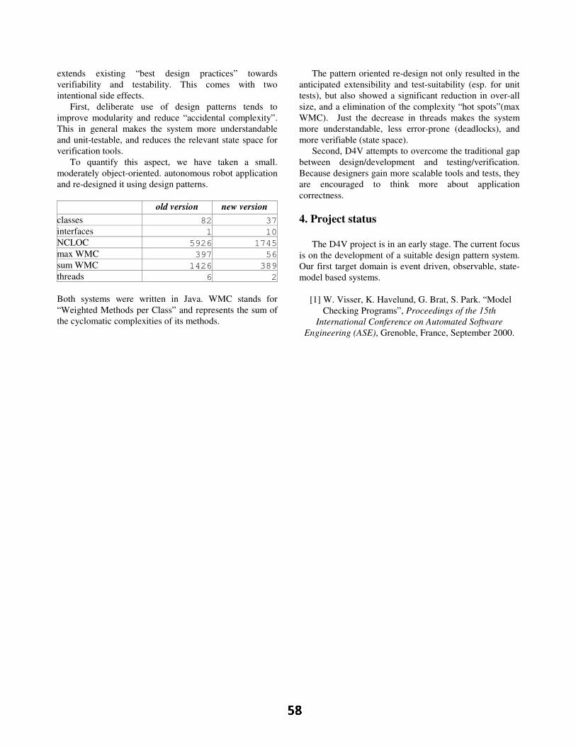
e x te n d s e x is tin g “ b e s t d e s ig n p r a c tic e s ” to w a r d s v e r ifia b ility a n d te s ta b ility . T h is c o m e s w ith tw o in te n tio n a l s id e e f fe c ts .
F ir s t, d e lib e r a te u s e o f d e s ig n p a tte r n s te n d s to im p r o v e m o d u la r ity a n d r e d u c e “ a c c id e n ta l c o m p le x ity ” . T h is in g e n e r a l m a k e s th e s y s te m m o r e u n d e r s ta n d a b le a n d u n it-te s ta b le , a n d r e d u c e s th e r e le v a n t s ta te s p a c e f o r v e r ific a tio n to o ls .
T o q u a n tif y th is a s p e c t, w e h a v e ta k e n a s m a ll. m o d e r a te ly o b je c t- o r ie n te d . a u to n o m o u s r o b o t a p p lic a tio n a n d r e -d e s ig n e d it u s in g d e s ig n p a tte r n s .
o ld v e r s io n n e w v e r s io n
c la s s e s 82 37 in te r f a c e s 1 10 N C L O C 5926 1745 m a x W M C 397 56 s u m W M C 1426 389 th r e a d s 6 2
B o th s y s te m s w e r e w r itte n in J a v a . W M C s ta n d s f o r “ W e ig h te d M e th o d s p e r C la s s ” a n d r e p r e s e n ts th e s u m o f th e c y c lo m a tic c o m p le x itie s o f its m e th o d s .
T h e p a tte r n o r ie n te d r e -d e s ig n n o t o n ly r e s u lte d in th e a n tic ip a te d e x te n s ib ility a n d te s t-s u ita b ility ( e s p . fo r u n it te s ts ) , b u t a ls o s h o w e d a s ig n if ic a n t r e d u c tio n in o v e r - a ll s iz e , a n d a e lim in a tio n o f th e c o m p le x ity “ h o t s p o ts ” ( m a x W M C ) . J u s t th e d e c r e a s e in th r e a d s m a k e s th e s y s te m m o r e u n d e r s ta n d a b le , le s s e r r o r - p r o n e ( d e a d lo c k s ) , a n d m o r e v e r if ia b le ( s ta te s p a c e ) .
S e c o n d , D 4 V a tte m p ts to o v e r c o m e th e tr a d itio n a l g a p b e tw e e n d e s ig n /d e v e lo p m e n t a n d te s tin g /v e r if ic a tio n . B e c a u s e d e s ig n e r s g a in m o r e s c a la b le to o ls a n d te s ts , th e y a r e e n c o u r a g e d to th in k m o r e a b o u t a p p lic a tio n c o r r e c tn e s s .
4 . P r o j e c t s ta t u s
T h e D 4 V p r o je c t is in a n e a r ly s ta g e . T h e c u r r e n t f o c u s is o n th e d e v e lo p m e n t o f a s u ita b le d e s ig n p a tte r n s y s te m . O u r fir s t ta r g e t d o m a in is e v e n t d r iv e n , o b s e r v a b le , s ta te -m o d e l b a s e d s y s te m s .
[ 1 ] W . V is s e r , K . H a v e lu n d , G . B r a t, S . P a r k . “ M o d e l C h e c k in g P r o g r a m s ” , P r o c e e d in g s o f th e 1 5 th
I n te r n a tio n a l C o n fe r e n c e o n A u to m a te d S o ftw a r e E n g in e e r in g (A S E ) , G r e n o b le , F r a n c e , S e p te m b e r 2 0 0 0 .

Abstract
Distributed, decentralized, and mobile systems arehighly dependent on the underlying network. Due to net-work connectivity failures, these systems must address theproblem of disconnected operation, i.e., continued func-tioning in the absence or near-absence of network accessi-bility. A number of existing approaches provide support fordisconnected operation by employing different techniques.What is currently missing, however, is a general under-standing of the applicability of these techniques to differentkinds of software systems, and the manner in which theyaffect the overall system dependability. This paper strivesto improve that understanding. We present a framework forclassifying disconnected operation solutions and assessseveral representative approaches according to the pro-posed classification. This study highlights several pertinentareas that are currently not supported, helping to motivateour future work.
1. Introduction
The emergence of mobile devices such as portable note-book computers, hand-held personal digital assistants(PDAs), and mobile phones, and the advent of the Internetand various wireless networking solutions make the com-putation possible anywhere. However, new challengesarise for software systems executing in such environments:they are becoming highly distributed, decentralized, andmobile, and therefore highly dependent on the underlyingnetwork. Unfortunately, network connectivity failures arenot rare: mobile devices face frequent and unpredictable(involuntary) connectivity losses due to their constant loca-tion change and lack of wireless network coverage; thecosts of wireless connectivity often induce user-initiated(voluntary) disconnection; and even the highly reliableWAN and LAN connectivity is unavailable between 1.5%and 3.3% of the time [25].
For this reason, network-dependent systems are chal-lenged by the problem of disconnected operation, wherethe system must continue functioning in the (near-)absenceof the network. Disconnected operation forces systemsexecuting on each individual host to operate independentlyfrom other network hosts. This presents a major challengefor the software systems that are highly dependent on net-work connectivity, because each local subsystem is usuallydependent on the availability of non-local resources. Lackof access to a remote resource can halt a particular sub-system or even make the entire system unusable.
There are several possible solutions to increasing the
dependability of highly distributed and decentralized soft-ware systems in face of the connectivity losses:• make remote data available locally,• make remote code available locally,• make remote dynamic system state available locally,• reroute the communication in cases of partial disconnec-
tion from the network, and• delay remote interactions until the connection is reestab-
lished.The goal behind each of these solutions is to tempo-
rarily mask the absence of connection by mimicking thesystem’s continuous connectivity. The inconsistencies thatmay result from applying these solutions need to beresolved once the connection is re-established. Each ofthese solutions can be provided in a number of differentways, depending on the nature of the target application andon those aspects of the application’s dependability that areof primary concern (e.g., availability, performance, scal-ability, security).
Most commonly used techniques for supporting discon-nected operation are:• Caching – locally storing remote data once it has been
accessed in anticipation that it will be needed again [12], • Hoarding – prefetching the likely needed remote data
prior to disconnection [13],• Queueing remote procedure calls – buffering remote,
non-blocking requests and responses during disconnec-tion and exchanging them upon reconnection [11],
• Deployment and redeployment – installing, updating, orrelocating a distributed software system [1],
• Replica reconciliation – synchronizing the changes madeduring disconnection to different local copies of the samecomponent [12],
• Code mobility – dynamic change of the bindings betweencode fragments and locations where they are executed [8].What is currently missing, however, is a general under-
standing of the applicability of these techniques to differentkinds of software systems, how and under what conditionsthey may be used (possibly in concert), how they affect theoverall system dependability, and so forth. Also unclear isthe applicability of these techniques in the growing class ofarchitecture-centric, component-based software systems[18,19]. We believe that an understanding of these issuescan help both to streamline existing and to develop futuretechniques in support of this area. This paper strives toimprove that understanding. We present a framework forclassifying disconnected operation solutions. We have per-formed an extensive study of existing techniques and iden-tified a common set of criteria for their classification. In
Toward a Framework for Classifying Disconnected Operation Techniques
Computer Science DepartmentUniversity of Southern California
Los Angeles, CA 90089-0781 U.S.A.{marija, neno}@usc.edu
Marija Mikic-Rakic Nenad Medvidovic

turn, we have assessed several representative solutionsaccording to the proposed classification. While this is still awork in progress, it has already clearly identified areas notaddressed by current solutions. These areas, coupled with astudy of the compatibility of different techniques, willframe our future research agenda.
The rest of the paper is organized as follows. Section 2presents an overview of existing disconnected operationtechniques. Section 3 describes our classification frame-work and assesses several representative solutions based onthe identified criteria. The paper concludes with a discus-sion of open issues that will frame our future work.
2. Background
In this section we present an overview of existing dis-connected operation solutions. They are organized accord-ing to the general approach they adopt.
2.1. Availability of data
2.1.1. Distributed file systems. Most of the early work ondisconnected operation has been in the area of distributedfile systems. Coda [12], Ficus [9], and D-NFS [6] haveincluded extensive support for distributed file replicationduring disconnection and synchronization of replicas uponreconnection. These approaches use techniques such ascaching and hoarding for file replication, and logging andversion vectors for replica reconciliation. D-NFS and Codaalso introduced the notion of an agent, which represents anintermediary between client and server components thathandles their interaction during disconnection. An agentoperates in two modes: connected and disconnected. In theconnected state the agent forwards all of the client requeststo the real server. This allows the agent to monitor clientoperations and prepare the application for disconnectedoperation. In the disconnected mode, the agent performs thenecessary tasks (such as logging the client operations)needed to synchronize the replicas upon reconnection.While Coda and D-NFS focus on client-server applications,Ficus provides support for more general, peer-to-peer appli-cations.
PFS [4] provides support for partially connected opera-tion using a three-tier model, where an intermediary PFShost is inserted between a file server and a mobile client.PFS is a pseudo server for the mobile client and a pseudoclient for the file server. This extra level of indirectionenabled an efficient solution for partial disconnection, witha tolerable overhead during full connection. PFS provides ageneric interface for application-directed adaptation tovarying network quality of service requirements.
2.1.2. Distributed databases. In the area of distributeddatabases, disconnected operation has been addressed byapproaches such as Thor [2], and Bayou [22].
In Thor, a relevant subset of database objects is cachedprior to disconnection. Each transaction is logged duringdisconnection, but the clients can only perform “weak”transactions while disconnected. These transactions arecommitted only if they do not conflict with the transactionsperformed on the server.
Bayou is a platform of replicated, highly available, vari-able-consistency, mobile databases on which collaborativeapplications are built. Bayou focuses on providing applica-
tion-specific conflict detection and resolution.The main focus of both distributed file system and data-
base approaches has been on supporting continuous avail-ability of (passive) data only. Hence, they do not providesupport for applications whose mode of operation duringdisconnection depends also on the availability of remotecode and/or remote system state.
2.2. Availability of code
Providing continuous availability during disconnectionby employing code mobility techniques has been the focusof approaches such as Rover [11], Jamp [23], Mobileextensions (ME) [3], Odyssey [17], and FarGo-DA [24].
The Rover toolkit provides two major programmingabstractions: relocatable dynamic objects (RDOs) andqueued remote procedure calls (QRPC). RDOs representmobile code that can be dynamically loaded from a remoteserver and cached locally, while QRPC queues remoterequests during disconnection and dispatches them uponreconnection. Rover uses version vectors to detect conflictsbetween different instances of a given RDO.
Jamp provides abstractions that support the migration ofgroups of objects and classes between nodes of the net-work. However, Jamp does not support object replicationand, since mobile objects can only be in one location at atime, does not provide facilities for conflict resolution.
Mobile extensions (ME) provides location-independent,extensible facilities for deploying Web-based services. MEmakes use of caching, hoarding, asynchronous messaging,and application-level adaptation to cope with network fail-ures. This approach provides flexible and automaticresource management, since its employed techniques suchas caching and hoarding can dramatically increase resourcedemands.
Odyssey is a set of extensions to the NetBSD operatingsystem to support adaptation for a broad range of mobileinformation access applications. Odyssey provides moni-toring of various system resources, notifies running appli-cations of relevant changes, and enforces resourceadaptation decisions. However, each application indepen-dently decides how to adapt to the notified change.
FarGo-DA is a programming model and a runtime infra-structure for automatic reconfiguration of an applicationduring disconnection. FarGo-DA advocates disconnectedoperation awareness at system’s design time. Additionally,since FarGo-DA is targeted at resource-constrained plat-forms, its main consideration is limited memory on suchplatforms. For this reason, FarGo-DA proposes the use ofmulti-modal components in which the developer specifiesseparate subcomponents to be used during connection anddisconnection. Usually the subcomponent used during dis-connection provides a subset of connected-mode function-ality. Additionally, FarGo-DA assumes that the applicationdeveloper provides the conflict resolution code as part ofthe multi-modal component.
It should be noted that none of the described code mobil-ity techniques support automated selection of componentsthat should be migrated, nor do they perform any analysisof the effects of code mobility on the running system.
2.3. Ad-hoc networking
In the area of ad-hoc networking, several approaches

have been proposed, including packet rerouting protocols(FORP [21]), predictive connection management with userinput (PCP [14]), and adaptive wireless and mobile net-working (Monarch [10]). These approaches are focusing onthe mobility of the (human) user and are providing differ-ent techniques for rerouting when a mobile host changeslocation. However, they do not focus explicitly on discon-nected operation, and therefore do not provide any supportfor the operation of a mobile client if it is completely dis-connected from the network.
2.4. Other techniques
Some techniques have taken a more general approach todisconnected operation in which network disconnectionrepresents only one point of failure in a given system. Fail-ures of individual components are also examined andtreated in a manner comparable to network failures. Thegoal of these techniques is to ensure that the system’s oper-ation will degrade gracefully in the face of failures. Repli-cation is primarily used for increasing the reliability ofindividual components. An example such approach isRoSES [20], which provides a scalable framework for theanalysis and design of system-wide graceful degradation.
3. Classification framework
3.1. Description
The overall structure of our proposed classificationframework for disconnected operation approaches is orga-nized around eight categories, as shown in Figure 1. Eachcategory may have multiple dimensions, subdimensions,and values. The values are not necessarily mutually exclu-sive, meaning that a single approach may have zero, one, ormultiple values corresponding to a given category, dimen-sion, or subdimension. It should be noted that it was notour goal to identify all possible values in Figure 1 butrather to extract representative values from the existingapproaches. We expect that the list of values will grow aswe refine our classification framework. Missingapproaches corresponding to values in Figure 1 indicatethat no existing approach supports the corresponding prop-erty. Various other techniques exist that may be effectivelyapplied in the context of disconnected operation (e.g.,dynamic software architectures [5]). However, we feel thatincluding such techniques in our framework at this timewould be speculative as their effectiveness in this settinghas not been demonstrated. In the remainder of the sectionwe discuss each of the proposed classification categories inmore detail.
3.1.1. Connectivity. Connectivity encompasses informa-tion about the nature of disconnection that a givenapproach supports (type) as well as how the detection ofdisconnection is achieved.
Connectivity type is further divided into two subdimen-sions: predictability and degree of connectivity. Predict-ability can have two values: anticipated and sudden. Incases of anticipated disconnection the system is aware thatdisconnection is going to occur, and usually can predictwhen it will happen [14]. In cases of sudden disconnection,the system is unaware of the disconnection beforehand.
We have identified the following values for the degreeof connectivity: total, partial, and low-bandwidth. In cases
of total disconnection, a given host is completely discon-nected from the network. In cases of partial disconnection,the host is disconnected from the remote host with which itcommunicates, but there may be other hosts in the systemto which this host is still connected, or can be connected. Incases of low-bandwidth connection, the host is connected,but through a low throughput connection. Low throughputconnections necessitate the use of special techniques (e.g.,compression) that would minimize the use of bandwidth.
Connectivity detection is further divided into two subdi-mensions: accuracy and source. Accuracy denotes whetherdisconnection is detected with no loss of data, by losing asingle remote invocation (event), after which the sub-system recognizes that it has been disconnected andadjusts, or by losing multiple remote invocations. There arethree possible sources of disconnection detection: (1) exter-nal agent, denoting a source (e.g., OS service) that is not apart of a given disconnected operation approach; (2) perhost, denoting detection if an entire given host gets discon-nected; and (3) per component, denoting detection of dis-connection of individual software components.
3.1.2. Component types. The component types categoryincludes information about the kinds of software compo-nents whose availability in the face of disconnection is sup-ported by a given approach. This category is furtherdivided into active and passive components. Active com-ponents can be computation, communication, coordination,or interface components, while passive components can befiles or dynamic data structures.
3.1.3. Architecture. The approaches described inSection 2 use techniques such as component replication,migration, or network rerouting to increase the dependabil-ity of software systems during disconnection. However,these changes to a software system’s architecture may haveunforeseen effects on the running system. It is thus impor-tant to analyze the effects of the proposed changes prior toenacting them.
Static analysis may use (partial) architectural models toassess the validity of proposed run-time architecturalchanges prior to their deployment, possibly disallowing thechanges. Dynamic analysis refers to the analysis performedafter the deployment, of the effects of the performed modifi-cations on the running target system. These techniques aredescribed in more detail in [15].
In addition to the need for analyses, most of theapproaches described in Section 2 impose certain architec-tural topology restrictions on the supported applications,such as client-server or peer-to peer. An important decisionfactor in determining the most suitable approach for agiven system would be whether the system’s topology issupported by the given approach.
3.1.4. Use of bandwidth. As outlined in the Introduction,partial or low bandwidth network connectivity is oftenpresent in highly mobile systems. In such cases, there is acritical need for efficient access mechanisms over networkswith variable qualities of service. In our taxonomy, use ofbandwidth is divided into two dimensions: intelligence andefficiency. Intelligence indicates whether a given approachuses an adaptive algorithm to optimize the use of band-width, while efficiency indicates whether the approachminimizes the use of bandwidth in cases of low bandwidthconnection.

Type
Predictability
Degree
Criteria Dimension Subdimension Value
Figure 1. Classification Framework for Disconnected Operation Techniques.
Anticipated disconnection
Sudden disconnection
Total disconnection
Partial disconnection
Low bandwidth connection
Detection
Accuracy
Source
No loss of data
Single event lost
Multiple events lost
External agent
Per host
Per component
Component
Active
Computation
Coordination
Interface
Files
Dynamic data structures
Communication
Passive
types
Use of
Intelligence
Efficiency
Adjustable
Constant
Inefficient
Efficient
bandwidth
Considerationof systemresources
Software
Hardware
Shared resources
Memory
CPU
Battery
Display
Permanent storage
Technique
Application-level
System-level
Replication
Messaging
Fixed granularity cachingVariable granularity
Hoarding
Asynchronous
Deferred synchronous
Multi-mode components
Intelligent agents
caching
Re-routingNetwork topology based
Arch. topology based
Manual (just reporting)
Semi-automatic
Fully automatic
Instant
Scheduled
Upon reconnection
Firm
Delayed Type
Management
Occurrence
Consistency
Availability
ScalabilitySecurity
Performance
Non-functional propertiesconsidered
Application-level
System-levelThreads
(e.g., database,GUI builder)
Processing components
Data components
Architecture
Static
Dynamic
Approaches
Coda, Ficus, D-NFS, PFS, Thor, Bayou, Rover, Jamp, FarGo-DA, ME, Forp
Coda, Ficus, D-NFS, PFS, Rover, ME
Coda, Ficus, D-NFS, PFS, Thor, Rover, Jamp, FarGo-DA, ME
Coda, PFS, Rover, ME, Odyssey
Coda, Ficus, D-NFS, PFS, Thor, Bayou, Rover, Jamp, FarGo-DA, ME
D-NFS, Thor, Rover, Jamp, ME
Coda, Ficus, D-NFS, PFS, Bayou, Odyssey
Coda, PFS, Odyssey
Coda, PFS, Odyssey
Coda, Ficus, D-NFS, Bayou
Coda, Ficus, PFS, Thor, ME, RoSES
Coda, Ficus, D-NFS, Bayou
Coda, Ficus, D-NFS, ME
Coda, Ficus, D-NFS, Thor, FarGo-DA
Application specific
Coda, Ficus, RoSESCoda
PFS, Rover, ME
Application-directed PFS, Rover, FarGo-DA, ME, RoSES
PFS, Thor, Bayou
PFS
PFS, Thor, Rover, ME, Odyssey
Thor, Bayou
D-NFS, Ficus, Thor, Bayou, Rover, Jamp, FarGo-DA, ME
D-NFS, Ficus, Thor, Bayou, Rover, Jamp, FarGo-DA. ME
Thor
Rover, Jamp, FarGo-DA, ME, Odyssey
Rover, ME, RoSES
Rover, ME, RoSES
Rover, Jamp, FarGo-DA, ME, Odyssey
Rover, Jamp, FarGo-DA, ME, Odyssey
Rover, Jamp, FarGo-DA, ME, Odyssey
FarGo-DA, ME, Odyssey
FarGo-DA, RoSES
FarGo-DA
Forp, Bayou, PCP, Monarch
Forp, Odyssey, PCP, Monarch
Coda, Ficus, PFS, Forp, Odyssey
Forp, PCP, Monarch
Connectivity
Coda, Ficus, D-NFS, Thor, Bayou, Rover, FarGo-DA, ME, Forp, PCP, Monarch
Analysis
TopologyClient-server
Peer-to-peer
Coda, D-NFS, PFS, Bayou, FarGo-DA, ME, Odyssey
Ficus, Jamp
Bayou
ME, Odyssey
ME, Odyssey
ME, Odyssey, RoSES
Odyssey
Odyssey

3.1.5. Consideration of system resources. Dependabilityof a destabilized system is influenced by many factors.When selecting an approach that supports disconnectedoperation, it is important to know whether the approachconsiders the effects of the proposed changes on the systemresources, and whether the available system resources on aset of affected hosts impose any restrictions on the pro-posed changes. If component migration is proposed by agiven approach, it is important to assess whether the targetdevice provides hardware resources (e.g., memory, CPU,display size) that the migrant component requires for nor-mal operation. It is also important to assess the effects ofsoftware resources available on the target host (e.g.,threads, existing processing components and their loads)on the migrant component. In our taxonomy, softwareresources are classified into system-level resources andapplication-level resources.
3.1.6. Technique. As outlined in the Introduction, there area number of commonly used techniques for increasing sys-tem dependability during disconnection. We have classifiedthese techniques into system-level and application-level.
System-level techniques are provided either at kernel-or middleware-level, and are further divided into replica-tion, messaging, and rerouting. Replication subsumes tech-niques such as caching and hoarding, while messaging useseither asynchronous or deferred synchronous communica-tion to delay remote interactions during disconnection.Synchronous messaging is not a feasible technique for sup-porting disconnected operation, since involved componentswould block for unpredictable periods of time.
Re-routing is a technique used to discover alternatepaths of communication between mobile hosts. This subdi-mension can have two values: network topology, or archi-tecture topology based rerouting. Network topology usesthe information about the physical location of a given hostand the network coverage of a given area. On the otherhand, architecture topology uses additional informationabout the allowed communication paths among softwarecomponents on each host to determine possible reroutingstrategies. Both of these techniques can only support dis-connected operation in cases of partial disconnection.
In the contrast to the above system-level techniques,several approaches [16,24] have proposed the use of appli-cation-level adaptation to increase system dependabilityduring disconnection. For example, multi-modal compo-nents are designed with the a-priori knowledge that theymay be executing in a disconnected mode. These compo-nents thus encapsulate two modes of operation: discon-nected and connected. It is the responsibility of theapplication developer to design and implement a compo-nent’s functionality such that it can be used during discon-nection. The disconnected mode usually involves a subsetof connected mode functionality, as well as methods forautomated runtime conflict resolution.
Intelligent agents are special-purpose componentswhose role is to perform a set of activities which wouldtranslate a running application from a connected mode to adisconnected mode and vice versa.
3.1.7. Consistency. Several of the techniques described inSection 2 perform data, code, or system state replication tohandle disconnected operation. Replication may requirethat changes made to different copies of a given componentbe synchronized upon reconnection. We have identified
three dimensions of consistency: type, management, andoccurrence.
Type denotes the extent to which the states of differentreplicas may diverge before they are synchronized. In firmconsistency, the states of all replicas are always the same.This is achieved by either disallowing the updates to differ-ent replicas or by performing simultaneous, blockingupdates to all replicas. In delayed consistency, replicas canbe in different states, and consistency management (i.e.,replica reconciliation) is performed upon reconnection.Some approaches also allow application-directed type ofconsistency, i.e., specification of (possibly different) con-sistency types for each application-specific operation.
Consistency management denotes the manner in whichthe reconciliation is performed. Some approaches justreport inconsistencies, which are then resolved by theapplication user. In semi-automatic management, someconflicts are resolved automatically, while others arereported to the user for (manual) resolution. Finally, in fullyautomatic management all conflicts are resolved automati-cally, without the user’s involvement.
Occurrence denotes the time at which the reconciliationis performed. In cases of instant reconciliation, each updatewill result in an immediate attempt to reconcile all replicas.In cases of scheduled updates, updates are planned and per-formed according to some, usually component-specificalgorithm. Most of the existing approaches perform recon-ciliation upon reconnection. Finally, some approaches pro-vide application-directed scheduling of reconciliation.
3.1.8. Non-functional properties. Existing disconnectedoperation approaches have considered different non-func-tional properties in the interest of increasing systemdependability. Most commonly considered non-functionalproperties are availability, performance, security, and scal-ability. There are other relevant non-functional propertiessuch as safety, reliability, utility, and so on. However, noexisting disconnected operation approaches have focusedon these properties.
3.2. Assessment of existing approaches
We have classified a number of representativeapproaches using our framework. The results of this classi-fication are shown in the right-most column in Figure 1. Inthe remainder of this section we discuss these results.
Most of the existing approaches focus on anticipateddisconnection, and on maximizing the system’s availabilityduring disconnection. Coda, PFS, ME, and Rover supportboth anticipated and sudden disconnection and providesupport for low-bandwidth connection. With the exceptionof Bayou, partial disconnection is supported only by ad-hoc networking approaches (recall Section 2.3).
Coda, PFS, and Odyssey make intelligent and efficientuse of the network bandwidth. However, none of theremaining approaches adjust their operation for a low-bandwidth connection. Instead, they assume either fullyconnected or disconnected mode of operation.
With the exception of Fargo-DA (for memory), onlyME and Odyssey take into consideration system resources(CPU, disk space, battery, and so on). These approachesrecognize that a given mobile host will not have unlimitedresources to fully support techniques such as hoarding, andthat certain trade-offs have to be made (e.g., providing con-tinuous availability of only the most frequently used com-

ponents). Fargo-DA, ME, and Odyssey use application-level dis-
connected operation techniques, while the remainingapproaches leverage different combinations of system-level techniques. The most commonly used system-leveltechnique is (some form of) replication, while theapproaches that employ delayed communication via mes-saging only use asynchronous messaging.
Finally, none of the studied approaches perform anykind of analysis of the effects of the changes on the runningsystem. They also fail to take into consideration other soft-ware resources (e.g., number of threads), or perform archi-tecture-based re-routing (recall Section 3.1).
4. Conclusion
In this paper we have presented an attempt at classifyingthe existing disconnected operation approaches. A generalunderstanding of these approaches and the techniques theyemploy is needed to effectively support system dependabil-ity in the face of disconnection. The existing approachesattack the problem of disconnected operation from fourgeneral perspectives: data housed in (1) static files and (2)dynamic data structures, and functionality implemented inboth (3) inactive and (4) active software components. Typi-cally, an approach will focus on a specific subset of thesefour categories (e.g., support for off-line access to staticfiles only). Our classification framework is a step in thedirection of understanding the (in)compatibilities amongthe existing techniques and suggesting the best possibleapproach or combination of approaches (e.g., coupling apassive file-based approach and an active component-based approach) for the problem at hand.
This work is preliminary and much remains to be done.A natural next step is to gain further experience by evaluat-ing additional known disconnected operation approachesusing the framework outlined in this paper. Such an evalua-tion will, in turn, be used to fine-tune the framework itself.In addition, we plan to study the compatibilities of the dif-ferent criteria, dimensions, subdimensions, and values,which would help with identifying techniques that can beused in concert. Finally, further study of existing discon-nected operation techniques will highlight additional areasthat are currently not supported, which would motivate andhelp to streamline our future work.
5. References [1] A. Carzaniga et. al. A Characterization Framework for Soft-
ware Deployment Technologies. Technical Report, Dept. ofComputer Science, University of Colorado, 1998.
[2] S. Chang and D. Curtis. An Approach to Disconnected Oper-ation in an Object-Oriented Database. 3rd International Con-ference on Mobile Data Management, January 2002,Singapore.
[3] M. Dahlin, B. Chandra, L. Gao, A. Khoja, A. Nayate, A.Razzaq, A. Sewani. Using Mobile Extensions to SupportDisconnected Services. University of Texas Department ofComputer Sciences Tech Report TR-2000-20, June 2000.
[4] D. Dwyer and V. Bharghavan. A Mobility-Aware File Sys-tem for Partially Connected Operation. In ACM OperatingSystems Review, Vol. 31, No. 1, Jan. 1997, pp. 24-30.
[5] Dynamic Software Architectures Resources. http://www.ics.uci.edu/~peymano/dynamic-arch/
[6] M. E. Fiuczynski and D. Grove. A Programming Methodol-ogy for Disconnected Operation. Technical Report, Univer-
sity of Washington, March 1994. [7] K. Froese and R. Bunt. Scheduling Write Backs for Weakly
Connected Mobile Clients. In Proc. of the 10th InternationalConference on Modelling Techniques and Tools for Com-puter Performance Evaluation, Palma de Mallorca, Sept.1998.
[8] A. Fuggetta, G. P. Picco, and G. Vigna. Understanding CodeMobility. IEEE Trans. on Software Engineering, May 1998.
[9] J. S. Heidemann et al., Primarily Disconnected Operation:Experiences with Ficus. Second Workshop on Managementof Replicated Data. IEEE, November 1992.
[10] D. B. Johnson and D. A. Maltz. Protocols for adaptive wire-less and mobile networking. IEEE Personal Communica-tions, 3(1), February 1996.
[11] A. D. Joseph, A. F. de Lespinasse, J. A. Tauber, D. K. Gif-ford, M. F. Kaashoek, Rover: a toolkit for mobile informa-tion access, Proceedings of the fifteenth ACM symposium onOperating systems principles, December 1995, Colorado.
[12] J. J. Kistler and M. Satyanarayanan. Disconnected Operationin the Coda File System. ACM Transactions on ComputerSystems, vol. 10, no. 1, February 1992.
[13] G. H. Kuenning and G. J. Popek. Automated Hoarding forMobile Computers. Proceedings of the 16th ACM Sympo-sium on Operating Systems Principles, (SOSP-16) St. Malo,France, October 5-8, 1997.
[14] M. Madi, P. Graham, and K. Barker. Mobile Computing:Predictive Connection Management With User Input. Tech-nical Report. Dept. of Computer Science, Univ. of Manitoba,1997.
[15] M. Mikic-Rakic and N. Medvidovic. Architecture-LevelSupport for Software Component Deployment in ResourceConstrained Environments. First International IFIP/ACMWorking Conference on Component Deployment. Berlin,June 2002.
[16] W. Nace and P. Koopman. A Product Family Approach toGraceful Degradation. In Proceedings of International Work-shop on Distributed and Parallel Embedded Systems, Ger-many, October 2000.
[17] B. Noble, et. al. Agile Application-Aware Adaptation forMobility. In Proceedings of the Sixteenth ACM Symposiumon Operating Systems Principles, St. Malo, France, October1997.
[18] D.E. Perry, and A.L. Wolf. Foundations for the Study ofSoftware Architectures. Software Engineering Notes, Oct.1992.
[19] M. Shaw and D. Garlan. Software Architecture: Perspectiveson an Emerging Discipline. Prentice-Hall, 1996.
[20] C. Shelton, et al. A Framework for Scalable Analysis andDesign of System-Wide Graceful Degradation in DistributedEmbedded Systems. WORDS 2003, January 2003.
[21] W. Su and M. Gerla. IpV6 Flow Handoff in Ad-Hoc WirelessNetworks Using Mobility Prediction. Proceedings of IEEEGlobal Communications Conference, pp 271-275, Rio deJaneiro, Brazil, December 1999.
[22] D. B. Terry, K. Petersen, M. J. Spreitzer, and M. M. The-imer.The Case for Non-transparent Replication: Examplesfrom Bayou. IEEE Data Engineering, December 1998.
[23] M. T. Valente, R. Bigonha, M. Bigonha and A. Loureiro.Disconnected Operation in a Mobile Computation System.Workshop on Software Engineering and Mobility, Toronto,Canada, May 2001.
[24] Y. Weinsberg, I. Ben-Shaul. A Programming Model and Sys-tem Support for Disconnected-Aware Applications onResource-Constrained Devices. International Conference onSoftware Engineering 2002, Orlando, Florida, May 2002.
[25] Y. Zhang, V. Paxon, and S. Shenkar. The Stationarity ofInternet Path Properties: Routing, Loss, and Throughput.Technical Report, AT&T Center for Internet Research atICSI, May 2000.

An Architecture for Configurable Dependability of Application Services
Matthias Tichy1 and Holger Giese1
Software Engineering GroupDepartment of computer science
University of PaderbornWarburger Str. 100, 33098 Paderborn, Germany
E-mail: [mtt|hg]@uni-paderborn.de
Abstract
Many human activities today depend critically on sys-tems where substantial functionality has been realized usingcomplex software. Therefore, appropriate means to achievea sufficient degree for dependability are required, which usethe available information about the software componentsand the system architecture. For the special case of service-based architectures – an architecture proposed to cope withthe complexity and dynamics of today’s systems – we iden-tify in this paper a set of architectural principles which canbe used to improve dependability. A service-based archi-tecture which extends Jini and employs the identified archi-tectural principles is further proposed and realized. Thedependable operation of the infrastructure services of thearchitecture further enables to systematically control andconfigure some dependability attributes of application ser-vices.
1. Introduction
The dependability of today’s complex systems often re-lies on the employed computers and their software compo-nents. Availability, reliability, safety and security (cf. [10])are the attributes of dependability that are used to describethe required system characteristics. These four attributes inpractice often depend on each other. Availability and relia-bility can in principle be systematically studied at the levelof components and their composition in form of specific ar-chitectures. The ever increasing system complexity and theincreasingly ubiquitous character of computing, however,render such an analysis a difficult task.
For complex systems the required prediction modelsfor availability and reliability become quite complex when
1This work was developed in the course of the Special Research Ini-tiative 614 – Self-optimizing Concepts and Structures in Mechanical En-gineering – University of Paderborn, and was published on its behalf andfunded by the Deutsche Forschungsgemeinschaft.
maintenance activities and component modifications arealso taken into account. When further considering dynamicsystems where no statica priori known system configura-tion exists, the analysis and prediction of the reliability oravailability is thus usually not possible. We therefore pro-pose to build dynamic and dependable complex systems notby relying on design-based quantitative analysis of its staticarchitecture. Instead the observed obstacles should be ad-dressed by a dynamic reconfiguration of the architecture toprevent system reliability and availability to decrease be-low the required level. Such a software tries to compen-sate failures (originated from defects of its hardware andsoftware components) by means of adaption. In accordancewith [12], which definesself-adaptive softwareas softwarethat modifies its own behavior in response to changes in itsoperating environment, we thus classify it asself-healingsoftware.
We further restrict our considerations for dependabilityon reliability and availability and study how the dynamicmanagement of redundant component instances with iden-tical implementation can contribute to improvements forthese two dependability attributes. The questionable im-pact of using multiple diverse implementations (cf. [7]) isnot considered. The application services are further treatedas black-boxes with given dependability characteristics. Wemake the strong simplification that hardware and softwarecomponent failures simply result in the inability of the af-fected services to fulfill the regular behavior. Thus, failurescan be detected externally by monitoring the services.
A number of architectural principles which permit to en-hance the dependability of service-based architectures arepresented in Section 2 and their benefits are motivated re-ferring to the Jini architecture. Then, we propose in Section3 to enhance the Jini architecture by a number of infras-tructure services that systematically employ the identifiedprinciples. We then discuss the benefits achieved for appli-cation specific services concerning availability and reliabil-

ity in Section 4 and demonstrate the systematic applicationof the identified architectural principles within the enhancedarchitecture. For a special class of services the possible de-sign alternatives are studied by means of the detailed designof two infrastructure services in Section 5. Related work isdiscussed in Section 6 and we close the paper with a finalconclusion and some comments on future work.
2. Architectural Principles for Dependability
Software systems typically consist of different parts.Since dependencies between these parts exist, problems oc-cur if a part fails. Service-based architectures handle theincreasing complexity of today’s systems by means of on-line lookup and binding of services. The integral part of aservice-based architecture is aservice registry. The use ofsuch a service registry is a key factor for availability, sinceservice instance connections are not hard-wired. Insteadthey can spontaneously connect to recover from failures.One example of a self-healing service-based architecture isthe Jini architecture [1, 13]. It has been designed (cf. [19])to support the development of dependable distributed sys-tems. One of its features is alookup servicethat remainsoperational even when single nodes in the network havecrashed.
The leasingprinciple extends the allocation of resourceswith time [18]. The lease represents a period of time duringwhich the resource is offered. Therefore this lease needsto be extended (renewed) if the resource remains to be of-fered after the timeout of the lease. If the owner of theresource fails to renew the lease, a client can assume thatthe resource is no longer available. Leasing is the principlewhich provides the self-healing behavior of the Jini lookupservice. Every service registration on the lookup service isaccompanied by a lease. If this lease expires, the lookupservice removes the accompanied service registration fromits lookup tables. Thus no service gets this apparently failedservice instance in response to a search request. If this ser-vice is restarted or the communication system is repaired,the service can re-register on the lookup service.
A proxyprovides a surrogate or placeholder for anotherobject [4]. In distributed systems a proxy typically acts asa local placeholder for a remote object encapsulating theforwarding of requests via network communication (e.g. asthe stub in Java Remote Method Invocation (RMI) [15]).In the Jini architecture the proxy pattern is an integral partof every service. A service is divided into a proxy and anoptional backend. The proxy instance is registered in thelookup service. If a service is to be used by a client, theproxy instance is downloaded as mobile code to the clientand executed there.
Redundancyof service instances is a key factor toachieve a required degree of availability. A non redundantservice is a single-point-of-failure. Thus in case of a fail-
ure of this service or a communication subsystem failure,which results in a network partition, all dependent clientsof that service cease to work. In the Jini architecture morethan one lookup service can be used. Thus a failed lookupservice does not compromise the dependability of the com-plete system.
This leads us to the concept of asmart proxy[9, 11].A smart proxy is not restricted to forwarding but can beused much more flexible. Thus in the context of availabil-ity the proxy may communicate with multiple backends atonce to recover from or mask failures. Hence a smart proxycan be used to encapsulate and hide the complexity of self-adapting code and therefore the use of complex conceptsbecomes transparent to the user of the service. For examplethe service registration in the Jini architecture is sent to allavailable lookup services by the proxy at once using multi-cast messages.
Analogue to the redundancy of services a key point fordependability is the availability of data in a distributed sys-tem. This can be achieved by the use ofreplication. Repli-cating is the process of maintaining multiple copies of thesame entity at different locations. In the Jini architecturethe service registrations are replicated in multiple lookupservices.
The maintenance of these distributed copies depends onthe required consistency for the entity. There exist differ-ent consistency models (for an overview see [16]). A con-sistency model provides stronger or weaker consistency inthe sense that it affects the values, a read-operation on adata item returns. There is a trade-off between consistencyand availability and no general solution can be given. Theweaker the consistency model the easier availability canbe achieved. The possibility to use different consistencymodels for different data aids in the development of a self-healing architecture as we will show in the next section.
3. Architecture
In this section we will show the application of the intro-duced architectural principles. We give a short introductionof the proposed architecture and the requirements of the dif-ferent infrastructure services. More details and the descrip-tion of the implementation can be found in [17].
The Jini architecture supports ubiquitous computing inad-hoc networks and provides a dependable infrastructurefor service lookup and operation. However, the basic infra-structure only avoids to provide any element that can com-promise the dependability of application components. Butto achieve the required dependability for any specific ser-vice or application remains to be realized by the applicationdeveloper. Our proposed architecture provides availabilityfor application services.
A key to the improved availability of the infrastructureservices is the idea to have redundant instances of every

service type running concurrently in the system to prevent asingle-point-of-failure as proposed in the last section. Keepthis idea in mind while we describe the specific infrastruc-ture services next.
Four different services are building the overall architec-ture on top of Jini. Ideally on every computation node ofthe system one instance of each infrastructure service is ex-ecuted and will be restarted automatically during each re-boot (see Figure 1).
Data access
b: Check
Registera.3:
a.1: Start a.2: Create
Responsibility
: Monitor: Service
Storage: Node
: Application Service: Jini Lookup
: Monitor
DescriptionStorage
Figure 1. Architecture
Basically on every node of the distributed system an in-stance of thenodeservice is running. Using this node ser-vice, new application service instances can be created (andold ones stopped).
A service description storagecontains service descrip-tions (like name of the service, package-path, used and pro-vided interfaces, deployment constraints, etc.) for all ser-vices which have to be executed. Each instance of the ser-vice description storage contains one replica of the servicedescriptions. A strong consistency model for these data isrequired since a weaker consistency model would result ina possible loss of service descriptions in case of failures.This in turn would cause the unavailability of the affectedapplication services.
Monitorssupervise that the services contained in the ser-vice description storage are indeed executed in the system.The availability of the services will be checked periodically.The detection speed of service failures can be configuredby changing this period. If more than one instance of onespecific application service has to be executed in the sys-tem, each instance is monitored by a different monitor. Tocontrol which monitor is supervising which service, everymonitor needs to acquire a responsibility for a service (i.e.to assure a new instance is started, if a service instance isnot available).
These responsibilities are stored in amonitor responsi-bility storage. Responsibilities are accompanied by a con-
figurable lease, which is used to detect failed monitors (i.e.the lease times out). Each instance of the monitor respon-sibility storage contains a copy of these monitor responsi-bilities. Inconsistencies between these copies only resultin changed responsible monitors and potentially additionalstarted service instances. Therefore we trade reliabilityfor overhead and weaken the consistency requirements forthese copies. Additionally after a repaired network partitionfailure merging the responsibilities in the former partitionsmust be possible. The monitors whose behavior depends onthese responsibilities must be able to cope with a weakerconsistency model.
4. Evaluation
After this short introduction to the different infrastruc-ture services we show how the architecture achieves avail-ability for application services in case of node failures andnetwork partition failures. Afterwards we show how toachieve a required degree of reliability for different cate-gories of application services based on the availability pro-vided by the architecture.
4.1. Availability
In case of a node failure different scenarios, w.r.t. fail-ures of a responsible monitor and monitored services, arepossible. The case that neither a responsible monitor nora monitor service is affected by the node failure is trivial.If a node is affected by the failure which does host onlyapplication services, the monitors responsible for these ap-plication services will detect the services’ failures becausethey do not renew their leases with the lookup service. Themonitors will choose new nodes for the application servicesand start new instances there. Figure 2 shows this scenario.Note the displayed monitor and lease periods, which influ-ence the achievable degree of availability.
:ApplX
:Lookup :Node:Monitor:ApplX
unavailable
ok
renew lease
mon
itor p
erio
d
leas
e pe
riodlookup(ApplX)
lookup(ApplX)
start
create
lease timeout
Figure 2. Node Failure
In the case of a failed responsible monitor and failedmonitored services the responsibility lease of this moni-tor times out and another monitor steps in. This monitorreplaces the failed monitor, and starts supervising the cur-rently unmonitored services which includes starting new in-

stances when needed. Figure 3 shows the leases and theevents in a condensed form.
responsibility lease
t
service lease
new resp. monitornode failure service restarted
s. lease
Figure 3. Monitor Failure
During a network partition failure, communication isonly possible inside the different partitions and no commu-nication can cross the borders between the different parti-tions.
A monitor, which has been responsible for services inthe complete network, is in one part of the system duringthe partition. In this part the monitor recognizes the absenceof some monitored services and restarts them. In the otherparts the monitor’s responsibility times out, other monitorsstep in, and create all needed service instances. Thus in eachpartition a responsible monitor and all service instances areavailable after a certain amount of time (cf. Figure 3).
After reuniting the different partitions, the responsibilitystorages are merged to determine a new unified responsiblemonitor. This new monitor takes over the service instancesstarted by the other responsible monitors in the other par-titions. Additionally it can consolidate the number of ser-vice instances in the reunited network. The monitors for-merly responsible in the other partitions stop monitoringtheir started service instances.
As seen the availability of application services (and theMean Time to Repair (MTTR)) can be configured by chang-ing the lease given by the Jini lookup service, the monitor-ing period and the responsibility lease. Therefore the pro-posed architecture can be customized for a high degree ofavailability.
4.2. Reliability
The presented architecture ensures the availability of theapplication services in the system. Nevertheless for eachapplication service there must exist a concept to achieve therequired degree of reliability based on the availability pro-vided by the architecture. Different categories of servicesrequire different approaches to achieve reliability.
According to [3] services can be categorized in termsof modeling anentity or containing an activity (session).A session service may either be stateless or stateful. Thestate of a session is the history of relevant actions executedthroughout this session. If an action is independent of theprevious actions, the service is stateless, if not it is stateful.An entity service always has a state (its local data).
For stateless session services it is irrelevant which ser-vice instance is used for a given action, since the actions are
independent of each other. Thus the availability providedby the architecture is sufficient. If a service instance fails,another instance can be used.
If a used stateful session service instance fails, just usinganother service instance from thereon does not work. Es-sentially the last state of the failed service instance must berecreated on the newly used service instance. Thus the his-tory (relevant actions) until the point of failure needs to bereplayed.
To achieve reliability for entity services it is necessary toreplicate copies of the entity over a number of nodes to beable to mask failures. Additionally the consistency of theseentities according to a suitable consistency model must beassured. This replication is highly application-specific andthus no general solution can be given. For example in ourarchitecture we have data with two very different require-ments (service descriptions and monitor responsibilities)which can be provided by appropriate consistency models(see section 5).
The implementation of the above mentioned conceptsleads to a reliable system, but unfortunately the maintain-ability of the resulting system deteriorates. We propose theusage of the smart proxy pattern to encapsulate the com-plexities of achieving reliability. Since the proxy does notfail independently of the using application, the client doesnot need to handle a failed proxy. Thus a service client onlyneeds to know the interface to the service and nothing aboutthe different means of accomplishing reliability. It uses thesmart proxy via an interface and all additional processingfor reliability is done internally in the smart proxy (see Fig-ure 4).
:Backend :Client:Smartproxy
Figure 4. Smart proxy
5. Design of Infrastructure Services
In the following we further describe in detail the designof two infrastructure services. These services serve as ex-amples how to achieve the required degree of reliability forentity services according to the last section.
Service Description Storage This storage contains thedescriptions of the services which must be available in thesystem. These descriptions are replicated in the system ona number of service backends. A strong consistency modelis required for this replication. Write operations are onlyexecuted by an administrator whereas read operations areregularly executed by the infrastructure services.

Since changes in the service descriptions happen rarely,the number of read operations on these descriptions sur-passes the number of write operations. For a certain degreeof the system’s reliability, it is necessary that the read opera-tions of the infrastructure services succeed with a very highprobability in case of failures whereas the write operationsare unimportant. To exploit this bias for read operations wehave chosen to implement theweighted votingapproach [5]which provides sequential consistency.
This approach offers the possibility to configure the reli-ability, based on the assumed distribution of read and writeoperations. Each node has a number of votes to weight itsdata. Additionally this number of votes can be changed tomatch the reliability of that node. The weighted voting ap-proach uses a voting where the needed read (nr) and writequorums (nw) can be adjusted as long as read-write quo-rums (nw + nr > n) and write-write quorums (2nw > n)overlap to prevent inconsistencies (n : number of votes).For our scenario we choose a highnw and a lownr toachieve a high probability for a successful read operation.
Multiple node failures can be masked as long as the re-quired number of votes is available to reach the requiredquorum. In case of a network partition read operations arepossible in every partition containing more thannr votes.Write operations are only possible in the rare case that onepartition contains more thannw votes.
The weighted voting approach is implemented in a smartproxy. Thus a client does not need to know about the spe-cific implementation; it just calls read and write operationson the proxy and all replication and consistency manage-ment is done internally.
Monitor Responsibility Storage Storing the monitor re-sponsibilities is a problem similar to storing the service de-scriptions. In contrast write and read operations are equallyimportant. In case of failures it is necessary that anothermonitor can take over the responsibility of a broken monitorand needs to write that information back into the responsi-bility storage.
Therefore we can weaken the consistency requirementsfor the responsibility storage to be able to read and writeto it anytime especially in the failure case. An appropri-ate weaker consistency model iseventual consistency[16].Eventual consistency demands that in absence of write op-erations the storages eventually stabilize in a globally con-sistent state after a certain amount of time.
Our approach to achieve eventual consistency is based onmulticast messages and a decentral majority voting on everyresponsibility storage in the network. Because of the multi-cast messages, every message is received by every storage.Thus, in case of a read operation, all available storages re-ceive the read request and respond by returning their localdata as a multicast message. Therefore every storage and
the requester get the responsibilities stored in every storage.Since the number of storages is unknown in case of fail-ures a timeout is used to finish waiting for responses. Afterthat, all storages and the requester do a decentral majorityvoting on the received data. In case of parity each partici-pant chooses the data with the highest hashcode to achievea consistent result. A write operation simply sends a writemulticast message which is processed by all storages, whichreceive the message.
Before a globally consistent state is reached there mayexist local inconsistencies. For example, during a networkpartition failure the local data in the storages in the differentpartitions diverge because updates are only visible withinone partition. After the failure is repaired the conflicts be-tween all partitions are resolved by the next read operation.After the decentral majority voting the data of only one par-tition holds, the others are discarded. Therefore only onemonitor is responsible for a specific service description. Allother, former responsible monitors notice their responsibil-ity loss on their next responsibility check.
From a user point of view this complex dealing with mul-ticast messages and the voting is completely encapsulatedwithin a smart proxy.
6. Related Work
In the Jini-context the problem of availability is some-what supported by use of the RMI-Daemon [15]. This dae-mon supports the on demand creation of remote objects.Additionally if the node fails, after a reboot and a restart ofthe daemon all remote objects are recreated. Neverthelessthis daemon only restarts the remote objects on the samenode. Therefore this is not a solution if a node fails perma-nently or if the remote objects should be available duringthe repair of the node.
The RIO-Project [14] uses a somewhat similar approachcompared to ours. One single monitor is loaded with theservice descriptions and ensures the availability of the con-tained services in the system. The fact that the service de-scriptions are only available inside of the monitor makes themonitor a single-point-of-failure in the system. If the moni-tor process fails, the service descriptions are lost since theyare not replicated. No other monitor can use those servicedescriptions and replace the existing monitor without man-ual intervention. Thus the reliability of the RIO approachdepends heavily on the reliability of one monitor instance.Additionally during a network partition failure the approachdoes not work since the monitor instance cannot be in morethan one partition of the network. Hence this approach isnot applicable for dependable systems.
The Master-Slave pattern [2] can be applied when ser-vices are replicated and a result must be selected which isreturned to the client. This is similar to our smart proxyapproach. The slaves are the different service instances

whereas the smart proxy is the master in our approach. TheMaster-Slave pattern is aimed at stateless session serviceswhereas our approach can also be used for the consistentmanagement of entity services.
The Willow-Architecture by Knight et al. [8] providessurvivability for critical distributed systems. As a responseto faults reconfiguration is used to ensure the survivabil-ity of the system. The response to failures is based on amonitor/analyze/respond-control loop which is similar toour behavior of the monitor.
Gustavsson and Andler describe in [6] a distributed real-time database which uses eventual consistency. Similar toour approach they use this consistency model to improvethe availability and efficiency and to avoid blocking for un-predictable periods of time.
7. Conclusions and Future WorkFor the proposed architecture implemented on top of
Jini, we have shown that the infrastructure services itselfbuild a dependable system. This includes that in contrast torelated proposals no single-point-of-failure for node crashesor network partition failures is possible. The number ofparallel running service instances and lease times for reg-istry and monitoring can be chosen. Thus for any architec-ture conform application specific service availability can beconfigured. For different kinds of application services wepresented appropriate concepts to also realize a higher re-liability. The required additional efforts are systematicallyhidden to the service clients using the smart proxy conceptof Jini. The smart proxy concept itself can be used in ev-ery service-based architecture. But the reliability providedby the presented architecture highly depends on the robust-ness of the underlying service-based architecture. To adaptit to other architectures than Jini, the leasing concept of Jinineeds to be reimplemented in the different application ser-vices to offer a Jini-like robustness.
In addition to the implementation of the presented de-pendable architecture and its run-time system, tool supportby means of UML component and deployment diagramshas been realized [17]. This includes code generation forthe services, generation of XML deployment descriptions,and the visualization of the current configuration by meansof UML deployment diagrams. We further plan to evaluatethe architecture in the context of complex embedded andreal-time systems. For small examples a formal analysisusing Markov models will be performed. Additionally, wewill look how run-time measurements of node, network andcomponent dependability characteristics can be employedto adjust the system parameters such as monitor supervisionperiods accordingly. In a next step, we want to employ clas-sical approaches for learning and adaption to automaticallyuse this feedback to improve the system’s dependability.
AcknowledgmentsThe authors wish to thank Sven Burmester, Matthias Gehrke,
and Matthias Meyer for comments on earlier versions of the posi-tion paper.
References[1] K. Arnold, B. Osullivan, R. W. Scheifler, J. Waldo, A. Woll-
rath, and B. O’Sullivan. The Jini(TM) Specification. TheJini(TM) Technology Series. Addison-Wesley, June 1999.
[2] F. Buschmann, R. Meunier, H. Rohnert, P. Sommerlad, andM. Stal. Pattern Oriented Software Architecture. John Wileyand Sons, Inc., 1996.
[3] L. G. DeMichiel, L. U. Yalcinalp, and S. Krishnan.Enter-prise JavaBeansTM Specification. Sun Microsystems, Au-gust 2001. Version 2.0.
[4] E. Gamma, R. Helm, R. Johnson, and J. Vlissides.DesignPatterns, Elements of Reusable Object-Oriented Software.Addison-Wesley, 1994.
[5] D. K. Gifford. Weighted Voting for Replicated Data. InProceedings of the seventh symposium on Operating systemsprinciples, volume 7 ofACM Symposium on Operating Sys-tems Principles, pages 150–162. ACM press, 1979.
[6] S. Gustavsson and S. F. Andler. Self-stabilization and even-tual consistency in replicated real-time databases. InPro-ceedings of the first workshop on Self-healing systems, pages105–107. ACM Press, 2002.
[7] J. Knight and N. Leveson. A reply to the criticisms of theKnight & Leveson experiment.ACM SIGSOFT Software En-gineering Notes, 15(1):25–35, January 1990.
[8] J. C. Knight, D. Heimbigner, A. Wolf, A. Carzaniga, J. Hill,P. Devanbu, and M. Gertz. The Willow Architecture: Com-prehensive Survivability for Large-Scale Distributed Appli-cations. InThe International Conference on Dependable Sys-tems and Networks (DSN-2002), Washington DC, June 2002.
[9] R. Koster and T. Kramp. Structuring QoS-Supporting Ser-vices with Smart Proxies. InProceedings of Middleware’00.Springer Verlag, April 2000.
[10] J. C. Laprie, editor.Dependability: basic concepts and ter-minology in English, French, German, Italian and Japanese,volume 5 ofDependable computing and fault tolerant sys-tems. Springer Verlag, Wien, 1992.
[11] P. Ledru. Smart proxies for jini services.ACM SIGPLANNotices, 37(4):57–61, Apr. 2002.
[12] P. Oreizy et al. An Architecture-Based Approach to Self-Adaptive Software.IEEE Intelligent Systems, 14(3):54–62,May/June 2002.
[13] Sun Microsystems.Jini Specification, October 2000. Revi-sion 1.1.
[14] Sun Microsystems. RIO - Architecture Overview, 2001.2001/03/15.
[15] Sun Microsystems. JavaTM Remote Method InvocationSpecification, 2002. Revision 1.8, JDK 1.4.
[16] A. Tanenbaum and M. van Steen.Distributed Systems, Prin-ciples and Paradigms. Prentice Hall, 2002.
[17] M. Tichy. Durchgangige Unterstutzung fur Entwurf, Imple-mentierung und Betrieb von Komponenten in offenen Soft-warearchitekturen mittels UML. Master’s thesis, Universityof Paderborn, Department of Mathematics and Computer Sci-ence, Paderborn, Germany, July 2002.
[18] J. Waldo. The jini architecture for network-centric comput-ing. Communications of the ACM, 42(7):76–82, 1999.
[19] J. Waldo, G. Wyant, A. Wollrath, and S. Kendal. A Note onDistributed Computing. Technical report, Sun MicrosystemsLaboratories, November 1994. TR-94-29.

An Approach to Manage Reconfiguration in Fault–Tolerant Distributed Systems
Stefano Porcarelli1, Marco Castaldi2, Felicita Di Giandomenico1, Andrea Bondavalli3, Paola Inverardi2
1Italian National Research Council, ISTI Dept., via Moruzzi 1, I-56134, [email protected], [email protected]
2University of L’Aquila, Dip. Informatica, via Vetoio 1, I-67100, Italy{castaldi, inverard}@di.univaq.it
3University of Florence, Dip. Sistemi e Informatica, via Lombroso 67/A, I-50134, [email protected]
Abstract
This paper deals with dynamic resource management forreal–time dependability–critical distributed systems. Re-quirements for such kind of systems span many domainssuch as time, survivability, and scalability and point outformidable challenges in terms of their fulfillment. An ar-chitecture is proposed, based on the agent distributed in-frastructure Lira, and enriched with statistical models fordecision-making capabilities. The aim of the proposed ar-chitecture is to provide adaptive system reconfiguration, re-sorting to a hierarchy of resource managers to cope withfault tolerance and scalability issues.
1 Introduction
Dependability has become a crucial requirement of cur-rent computer and information systems, and it is foresee-able that its importance will increase in the future at a fastpace. We are witnessing the construction of complex dis-tributed systems, which are the result of the integration of alarge number of low–cost, relatively unstable COTS (Com-mercial Off–The–Shelf) components, as well as previouslyisolated legacy systems. The resulting systems are beingused to provide services, which have become critical in oureveryday life. Since COTS and legacy components are notdesigned to achieve high dependability by themselves, theirbehavior with respect to faults can be the most disparate.Thus, it is paramount for these kinds of system to be able tosurvive failures of individual components, as well as attacksand intrusions, although with degraded functionalities. Thispaper contributes to fault tolerance in such framework, byfocusing on fault handling strategies [1], particularly on sys-tem’s reconfiguration.
The aim of system reconfiguration is to provide controlcapabilities over unanticipated events in order to maintainthe system in a certain desirable state. An effective recon-figuration policy highly depends on an accurate diagnosisof the nature of the unanticipated event, namely if a hard,physical fault is affecting the system, or environmental ad-verse conditions are causing a soft fault which will naturallydisappear in some time. It is out of the scope of this paper toaddress diagnosis issues; we concentrate on reconfigurationonly, which is triggered on the basis of information on thehealthy status of system components, assumed accessible toour management architecture.
The rest of the paper is organized as follows. Section 2describes our architectural approach towards a fault tolerantresource management policy. Section 3 details the overallsystem management architecture and Section 4 introducesa simple case study to illustrate our approach. Section 5briefly concludes the paper and points out some future re-search directions.
2 Our Approach for Adaptive ResourceManagement
A basic characteristic of our resource management archi-tecture is its ability to adapt to dynamic system conditions.Different degrees of adaptivity may be (theoretically) pos-sible, ranging from picking up the reconfiguration policyfrom a look-up table where policies have been pre-storedon the basis of off-line analysis, to completely dynamicdefinition of the best reconfiguration to perform. An in-termediate solution is that where a number of strategies arepre-planned, but the choice of which one is the most appro-priate given certain run-time system conditions is decideddynamically. The degree of dynamic decision making hasto be carefully harmonised with other possible system con-

straints. In fact, the design of a resource management in-frastructure for distributed systems is influenced by severalfactors, among which the nature of the event that triggers areconfiguration action, the size of the computational effortfor decision making, and timeliness requirements.
Adaptive resource management is very demandingnowadays; the approach we propose is mainly character-ized by two aspects. Firstly, we introduce a model-basedactivity, which provides on-line quantitative evaluation ofthe impact of different reconfiguration strategies and thushelps in the selection of the most appropriate one. Secondly,the decision making process is decomposed in a hierarchi-cal fashion, each level differing in the visibility of, and theability to act on, the portion of the system under its control.Resorting to a hierarchical approach brings benefits underseveral aspects, among which: i) favoring fault tolerance bydistribution of control; ii) avoiding heavy computation andcoordination activities whenever faults can be managed atlocal level; iii) facilitating the construction and on-line so-lution of analytical models; iv) favoring scalability.
In our framework, the Light–weight Infrastructure forReconfiguring Applications (Lira) [2] is used to performremote control and dynamic reconfigurations over singlecomponents or applications. Lira does not formally de-scribe the procedure of decision making, it only assumesthat a proper subsystem is in place, in charge of decidingwhen and in which way the system needs to be reconfig-ured. In this paper, we are enriching the Lira frameworkwith a hierarchical Decision Maker (DM) in charge of on-line selection of the reconfiguration policy to apply. TheDM exploits a model-based support to guide its decision.Lira monitors system and environment conditions passingthe state of components and applications to the DM as inputfor taking decisions.
Upon receiving inputs requiring a reconfiguration, theDM activates the model-based evaluator to devise the mostappropriate configuration and behavior to face the currentsituation [4]. For example, it permits to evaluate the de-pendability of a new architecture of the system achieved re-arranging resources due to faults, or to carry out cost-benefittradeoff choices. The output provided by the decision makeris a new system configuration; such output is then managedby Lira, to put into action the selected reconfiguration.
3 The Lira Management Infrastructure andthe Decision Maker
Lira is inspired to the Network Management [9] in termsof reconfiguration model and basic architecture. The re-configuration model of the Network Management is quitesimple: a network device, such as a router or a switch, ex-ports some reconfiguration variables and functions throughan Agent, which is implemented by the device’s producer.
These variables and functions exported by the agent aredefined in the MIB (Management Information Base) andcan be modified using the set and get messages of SNMP(Simple Network Management Protocol) [9]. For softwarecomponents, a reconfiguration is any allowed change in thecomponent behavior, while an application reconfiguration isany change in the application’s topology in terms of numberand location of components [6][5][11].
In the next sections we will first provide an overview ofthe Lira infrastructure, and then integrate in it the DecisionMaker.
3.1 The Lira Infrastructure
The Lira architecture specifies three elements: (i) theAgent, which acts on the managed components, imple-ments the reconfiguration logic and communicates withother Agents, (ii) the MIB which contains the list of vari-ables and functions exported by the agent, and (iii) theManagement Protocol, which allows the communicationamong the agents.
A Lira Agent is a program that runs on its own threadof control and communicates with other Agents in an asyn-chronous way, using the Management Protocol. There arefour kinds of agents organized in a hierarchical way [10](see Figure 1) and specialized in different tasks: (i) Com-ponent Agents (CompAgents), associated to software com-ponents, (ii) Host Agents, associated to the host where thecomponents are deployed, (iii) Application Agents (AppA-gent), which control part of the system (different compo-nents and hosts), (iv) and the Manager Agent (Manager),on the top of the hierarchy, that controls the whole system.Accordingly to the hierarchical structure, an agent has man-ager capabilities on the portion of the system under its owncontrol (helped in the decisions by the Decision Maker),while it is a simple actuator with respect to the higher levelagents. In this paper we are discussing a logical architec-ture without addressing the deployment of the agents on thehosts. Of course, it is a delicate issue for fault tolerance,since it is necessary to have separate containment regionsfor the monitoring units and the monitored ones.
The Component Agent (CompAgent) directly controlsand manages the component. Lira does not specify how thecomponent is attached to the agent, but it only assumes thatthe agent is able to act on the component. The logical modelof communication between CompAgent and component isthrough shared memory; in fact, the Component shares apart of its state with the Agent and explicitly allows the re-configuration. To avoid synchronization problems, the com-ponent has to provide atomic access to the shared state. TheCompAgent manages the component’s life-cycle by export-ing the functions start, stop, suspend, resume and shutdown.The function shutdown stops the component and kills the

agent. For monitoring purpose, the CompAgent exports apredefined read-only variable STATUS, which maintains thecurrent state of the component (starting, started, stopping,stopped, suspending, suspended, resuming). Each agent isable to notify the value of a variable to its manager, ad-dressed by the variable NOTIFYTO also defined in the MIB.
Comp
AgentComponent
MIB
AgentHost
MIBDecisionMaker
DecisionMaker
ApplicationAgent
MIB
Manager
DecisionMaker
MIB
ManagementProtocol
Host
Figure 1. Lira general architecture
The Host Agent runs on the host where components andagents must be deployed. It dynamically installs and ac-tivates components and agents by exporting the functionsinstall, uninstall, activate, deactivate. Moreover, this agentmaintains the lists of both installed and activated compo-nents on the host: these lists are exported in the variablesACTIVEAGENTS and INSTALLEDAGENTS. Note that theHost Agent does not manage components, but it monitorsand controls host’s resources and parameters. All the vari-ables and functions are specified in the MIB.
The Application Agent (AppAgent) is a higher levelagent which controls a set of components through the as-sociated CompAgents. These agents manage a subsystemas an atomic component, hiding the reconfiguration’s com-plexity and increasing infrastructure scalability.
The Manager is the highest level agent which has theglobal knowledge to control the whole system. AppA-gents communicate with the controlled components throughthe Management Protocol, so they are independent fromthe specific components and can be programmed by meansof an interpreted language: the Lira Reconfiguration Lan-guage. By means of this language, the agent’s developerdefines a reconfiguration as a function: the function is in-voked internally when the agent is acting in a manager role,or it is exported in the MIB and called by a manager whenthe agent acts in the actuator role.
The Management Protocol is inspired to SNMP, withsome modifications and extensions. Each message is eithera request or a response, as shown in the following table:
request responseSET(var name, var value) ACK(msg text)GET(var name) REPLY(var name, var val)CALL(func name, par list) RETURN(ret value)
Requests are sent by higher level agents to lower level ones
and responses are sent backwards. There is one additionalmessage, which is sent from agents to communicate an alertat upper level (even if in the absence of any request):
NOTIFY(variable name, variable value, agent name)
As in the Network Management, the MIB represents theagreement among agents that allows them to communicatein a consistent way. The MIB provides the list of variablesand functions exported by the agent which can be remotelymanaged. A function is usually a reconfiguration processthat the agent makes available for its manager. Note thatalso the predefined variables and functions that characterizethe different agents (for example, the variable STATUS orthe function stop in the CompAgent) are defined in the MIB.In [3] the MIB is presented in detail.
The Lira infrastructure described here was not createdwith dependability requirements, so we are investigatinghow to modify the infrastructure providing new featureswhich guarantee continuous monitoring and distributedmanagement of components and hosts, making Lira de-pendable itself.
3.2 Decision Maker
The decision maker takes decisions about system’s re-configuration. Decisions can be taken at any level of theagents hierarchy as proposed by Lira (four levels) and, con-sequently, the power of the reconfiguration is different.
The first, bottom level is that of a Component Agent. Atthis level, the Decision Maker can only autonomously de-cide to perform preventive maintenance on the controlledcomponent. At the second level, that of the Host Agent,the DM can decide about installation and de-installation ofsuch components. The third level concerns the ApplicationAgent; at this level, the DM’s reconfiguration capabilitiesspan all software and hardware resources under its respon-sibility. At the highest level there is the Manager agent,which has a “global” vision of the system; therefore the DMat this level can perform an overall reconfiguration. Aftertaking the decision on reconfiguration at a certain level, it issent to the lower level agents which act as actuators on thecontrolled portion of the system.
For the sake of simplicity, the status of each monitoredsystem unit may assume three values: Up indicating thatthe component is well working; Degraded indicating thatthe component is working in a degraded manner (e.g., in thecase the component is hit by a transient fault which reducesits functionalities); and Down indicating that the componentis definitely wrongly working (e.g., it is hit by a permanentfault). At each level of the decision making hierarchy, theDM perceives the behavior of each system unit visible atthe one-step lower level in terms of up, degraded or down.To make an example, at the manager agent level, the DM

has knowledge of the behavior of each application runningin the system, each one seen as single system unit; in turn,at application agent level, the DM has knowledge of the be-havior of each host involved in that application, again eachone seen as a single system unit, and so on.
According to the depicted hierarchical reconfigurationprocess, when an event triggering a reconfiguration actionat a certain level occurs, the DM at that level attempts thereconfiguration, if possible. In case it cannot manage thereconfiguration, it notifies the upper level DM about bothdetected problem and its healthy status. In turn, the upperlevel DM receiving such request to trigger a reconfiguration,uses such heathy status information, together with those ofthe other system units under its control.
As introduced in Section 2, the way to make decisionsmay be different. If it is possible to assume stochastic in-dependence among failure and repair processes of variouscomponents, the new reconfiguration scheme can be simplyretrieved from a look-up table where pre–evaluated policies(e.g. by means of combinatorial models, like fault tree) havebeen stored. If some environmental parameters may changeat the moment of the reconfiguration, combinatorial modelsmust be solved each time. In case the failure of a compo-nent may affect other related components, space–state mod-els are necessary. These are solved by the DM on the basisof the information collected from the subordinated agents.In this case, each unit component is modeled with a simplePetri net which describes its forecasted behavior given itsinitial state. It is in charge of the Decision Maker to solvesuch overall composed model as quickly as possible to takeappropriate decisions online identifying the most rewardingreconfiguration action among a pool of pre–defined options.
Therefore, the status of any controlled component (pro-vided by Lira) is used as input for the appropriate deci-sion maker, that reasons, decides and gives back as output(to Lira) the optimal reconfiguration action. Decisions aretaken resolving analytical models (not shown for brevity),essentially based on Deterministic and Stochastic Petri Nets(DSPN) [7], and solved by means of the tool DEEM [8].
Obviously, the correctness of the decisions depends bothon the accuracy of the models and on its input parameters.
4 A Simple Example: Path Availability of aCommunication Network
To better motivate our methodology a possible scenariois presented. A simple, but meaningful scenario, is the caseof distributed computing where two peer–to–peer clients onthe network are communicating. To prevent service’s in-terruption, we need to provide an adequate level of pathsredundancy among the clients involved in the communica-tion. We suppose to have a network topology where sixhosts are physically (wired) connected as shown in Figure
2. For management purpose, we consider the network di-vided in two subnetworks Net1 and Net2, which containthe hosts H1, H2 and H3, H4 respectively. The hosts H5
and H6, where the clients are deployed, are not included inthe managed network.
H1
H2
H3 H4
H6H5
Net 2
Net 1
Figure 2. Hosts physical connection
A logical communication network composed by logicalnodes connected through logical channels is installed onthe managed hosts. The nodes N1, N2, N3, N4 connectedthrough the channels a, b, c, d, e, f, g are deployed on thesubnetwork Net1, as shown in Figure 3. These channelsprovide different choices for establishing the communica-tion among the clients, as listed in Table 1.
H 1
H 2
clientClient
H 65H
N1
N3
N4N2
1Net
a
c
d
eb
g
f
Figure 3. Logical infrastructure topology
Path Route1 a–N1–c–N3–f2 a–N1–c–N3–d–N2–e–N4–g3 b–N2–e–N4–g4 b–N2–d–N3–f
Table 1. Available paths
These path options can be used to improve the overallavailability of the logical network by providing redundancy.The goal of the management infrastructure is to keep atleast two paths available between the clients involved in the

Manager
AA1
HA 2
HA 1
H 1
H 2
N1A1
N2A2
A3N3
N4A4
clientClient
H 65H
AA2
Net 1
Net 2
Figure 4. Lira infrastructure for the controllednetwork
communication. When a hardware or software fault causespaths failure, a reconfiguration is triggered to re-establishpath’s redundancy. In this example, we consider that mani-festation of both a hardware fault (such as a wired connec-tion’s interruption or a damage in the physical machine) anda software fault (at operating system, application and logi-cal communication level) have a fail-stop semantics, that isthe component stops working.
We are interested in monitoring paths availability, so fora path to be available, all the nodes and links in the corre-sponding route must be available. Note that failures of aparticular link or node may result in unavailability of morethan one path. For example, if node N3 fails, path 1, 2, and4 become unavailable.
4.1 Lira infrastructure
In this section we describe how the Lira infrastructureis instantiated to manage the network previously described(see Figure 4). Each host Hi is controlled by a Host AgentHAi, each subnetwork Neti is controlled by an Applica-tion Agent AAi, while the whole network is controlled bythe Manager. The hosts H5 and H6 are considered outsidethe network, so they are not controlled by host agents.
The logical network is also controlled by the Lira agents.The Component Agents Ai control the logical nodes Ni,and they are managed by AA1. AA1 may decide to performa reconfiguration (following the policies specified by theDecision Maker) if it has the necessary information, whileit has to ask the general Manager when a global reconfig-uration is needed and the local information is not enough.Figure 4 details the Lira management infrastructure.
Each CompAgent associated to a logical node exports theenumerated variable HEALTH STATE, which can assume
the values Up, Degraded, and Down. In addition to the de-fined variables and functions, each CompAgent Ai exportsthe variable CONNECTED NODES, i.e. the address list ofconnected nodes, and the function connectTo(Node nextN-ode), able to connect the local node with the (remote) nodespecified as parameter. The CompAgent manages also thelife cycle of the logical node, by exporting the functionsstart, stop, suspend, resume, shutdown, as defined in Sec-tion 3.
Each Host Agent exports the functions install, uninstall,activate, deactivate and the enumerated variable HEAL-TH STATE, whose possible values are Up, Degraded orDown. The result of diagnosis over each component isaccessible by the agent, and it is notified through a LiraNOTIFY message before a complete crash of the machine.Moreover, the host agent exports the read-only variableCONNECTED HOSTS, which contains the hosts physicallyconnected with the variable’s owner. For the host H2, thisvariable contains the list H1, H3. Note that a host agent caninstall and activate new logical nodes, creating new routingpaths, increasing redundancy and repairing software faults.
The Application Agent monitors the subsystem’s stateand makes it available by exporting the read-only vari-ables AVAILABLE PATHS, ACTIVE NODES and WOR-KING HOSTS. The first one contains the number of avail-able paths between the clients: for the subsystem controlledby AA1, the value is 4 (see Table 1). The second one main-tains the list of active nodes in the controlled network: inthe situation depicted in Figure 4, this variable for AA1 is{N1, N2, N3, N4}. The third one contains the list of stillworking hosts in controlled network: when HAi notifiesthat Hi is down, this variable is modified by the applica-tion agent. To change the network topology, the applica-tion agent exports the function connect(Node source, Nodedest), which is able to connect a source node to a destinationnode.
The Manager Agent controls the subnetworks Net1and Net2 by checking the WORKING HOSTS variable ex-ported by the AppAgents. Thus, it can arrange reconfigura-tions on the two networks.
4.2 Performing reconfigurations
Reconfigurations can be triggered both at AppAgent andManager Agent levels by their associate Decision Makers.Decisions are taken when a lower level agent notifies that itscontrolled component is faulty. Moreover, to prevent faultsof the agent itself, higher level agents proactively ask to thecontrolled agents for the value HEALTH STATE with a fre-quency T .
As an example of reconfiguration at the ApplAgent level,let’s suppose that the node N3 is starting to work in a de-graded manner: the associated agent A3 notifies the variable

HEALTH STATE with the value Degraded. AA1 receivesthe NOTIFY message, and it checks the path availability onthe controlled network. There are still more than 2 pathsbetween the clients (see Figure 3) even if one is degraded.In this case three different solutions can be pursued. Thefirst is continuing in the same degraded configuration. An-other is to temporarily bypass the node N3 creating a newlogical channel between N1 and N4 and waiting for restart-ing N3. In this case, the redundancy in terms of paths isreduced because only the first link of the paths is replicated.The third can be to activate a new node N5 on the host H2,and to connect it to the client and to the nodes N1 and N2,creating new paths. Obviously the different solutions havedifferent costs in terms of time, CPU consuming and pathsredundancy. It is responsibility of the DM to select the bestone.
We suppose to be in a case where there are not fail-ure/repair dependencies among components and transientphenomena tied to reconfiguration are negligible; then, sim-ple combinatorial models can be evaluated to take the ap-propriate decision. Assuming that, at given time, the failureprobability of a link or component is 10
−3 when in the Up
state, and 10−2 when in the Degraded state; for a com-
ponent which undergoes restart the failure probability be-comes 5 ∗ 10
−3 and links and components belonging to thenew path have probability 5∗10
−3, then the three configura-tions options can be compared in terms of failure probabilityPF . Table 2 summarizes the results of a fault tree analysis,and points out that the best choice is to restart the node N3.
Policy options PF
Working in degraded manner 1.73848 ∗ 10−8
Restart node N3 5.19695 ∗ 10−9
Set–up a new path 4.77510 ∗ 10−8
Table 2. Policy comparison
In this simple example, the decision can be based oncombinatorial models computed a priori. Relaxing theabove assumptions makes the analysis more complex by re-quiring dynamic resolution of state–based models.
5 Conclusions
This work presents an architecture for dependability pro-visioning which integrates Lira, a light-weight infrastruc-ture for reconfiguring applications, with a model–based De-cision Maker. In particular, our goal is to provide a dis-tributed real–time systems with fault–tolerance capabilities.We concentrate only on system reconfiguration as conse-quence of both faults of software components and host com-puters that can affect the system.
The work presented in this paper is still ongoing activ-ity and several extensions are currently under investigationto improve and validate our approach. Firstly, Lira infras-tructure has to be fault–tolerant itself and different solutionsare currently under investigation in this direction. Secondly,for validation purposes a prototype of the case study anda performability evaluation campaign have been planned.Another possible research direction is to improve error di-agnosis capabilities of each agent, to better calibrate systemreconfiguration.
Acknowledgements This work has been partiallysupported by the Italian MIUR in the framework of theproject “High Quality Software Architectures for GlobalComputing on Cooperative Wide Area Networks”.
References
[1] J. C. Laprie A. Avizienis and B. Randell. Fundamental con-cepts of dependability. Technical Report 01-145, LAAS,April 2001.
[2] M. Castaldi, A. Carzaniga, P. Inverardi, and A.L. Wolf. Alight-weight infrastructure for reconfiguring applications. InProceedings of 11th Software Configuration ManagementWorkshop (to appear), Portland, Oregon (USA), May 2003.
[3] M. Castaldi and N. D. Ryan. Supporting Component-basedDevelopment by Enriching the Traditional API. In Proc.of Workshop on Generative and Component-based SoftwareEngineering, Erfurt, Germany, October 2002.
[4] S. Porcarelli F. Di Giandomenico A. Chohra and A. Bon-davalli. Tuning of database audits to improve scheduledmaintenance in communication systems. In Proc. of 20thSAFECOMP, Budapest, Hungary, 2001.
[5] J. Kramer and J. Magee. Analysing dynamic change in soft-ware architectures: A case study. Proc. 4th Int. Conf. onConfigurable Distributed Architecture, pages 91–100, 1998.
[6] J. Magee. Configuration of Distributed Systems. In M. Slo-man, editor, Network and Distributed Systems Management.Addison-Wesley, 1994.
[7] M. A. Marsan and G. Chiola. On petri nets with deterministicand exponentially distribuited firing times. In LNCS, volume266, pages 132–145. Springer Verlang, 1987.
[8] A. Bondavalli I. Mura S. Chiaradonna R. Filippini S. Poliand F. Sandrini. DEEM: a tool for the dependability model-ing and evaluation of multiple phased systems. In Proc. ofDependable Systems and Networks, New York, USA, 2000.
[9] Marshall T. Rose. The Simple Book: An Introduction to Net-working Management. Prentice Hall, April 1996.
[10] Michel Wermelinger. A Hierarchic Architecture Model forDynamic Reconfiguration. In 2nd Int. Workshop on SoftwareEngineering for Parallel and Distributed Systems, 1997.
[11] A. J. Young and J. N. Magee. A flexible approach to evolu-tion of reconfigurable systems. Proc. of IEE/IFIP Int. Work-shop on Configurable Distributed Systems, March 1992.

Dependability in Software Families
Frank van der Linden Philips Medical Systems, Veenpluis 4-6, 5684 PC Best, NL
abstract The paper gives an overview on dependability is-sues in software families. Most of these issues and the corresponding approach was originating from a series of industrial and research co-operation projects. Many of the results can only be regarded as being preliminary.
1. Introduction The organisation of software in families is a means to plan and manage reuse. Moreover by building systems in families the quality of the resulting products is expected to improve, because a large part of the software is (re-) used within many products, and therefore it is tested in many real-life situations. Initial involvement of the au-thor with family development, incorporating dependabil-ity issues, [12][13] resulted in a series of projects, on the topic of system family development, ARES [9], ESAPS [15] and CAFÉ [16]. Within these projects we have identified the interdependence of 4 software develop-ment concerns, BAPO [1]: • Business, how to make profit from your products • Architecture, technical means to build the software • Process, roles, responsibilities and relationships
within software development • Organisation, actual mapping of roles and responsi-
bilities to organisational structures.
2. Families, BAPO and dependability A set of products is forming a software family if it is based upon the same technological basis (architecture), and there is a clear management of the variation between them. The main reason to set up a family is to save cost and labour, by not making the same functionality twice. Family assets are built independently from the products
that use these assets. This means that in order to main-tain a dependable family, the dependability issues have to be managed both for the family assets and for the re-sulting products. In the next sections we discuss the de-pendability considerations for the different BAPO as-pects.
Business An important business decision is the definition of the scope of the family [21]. The scope determines which systems will be part of the family. Dependability issues play a role in the scoping decisions in several ways: • What is commercial value of a certain quality, • What are the costs of the introduction of, or main-
taining, a specific quality level in (a part of) the family,
• Which parts of the family should exhibit which quality level,
• How to assess the quality levels of the resulting products
In order to relate business originated quality goals to ar-chitecture decisions in a family development context, a divide and conquer approach is often useful. For instance, in [19] an investigation is made on the quality goals a business may have, and how these goals relate to archi-tecture attributes. It results in a set of separate quality re-lated taxonomies, each with different characteristics. These taxonomies are related to business originated qual-ity goals. It considers, for example, performance, cost, and variability taxonomy. Such taxonomy is used to de-termine what are the business originated quality goals, and how to solve them. Part of the taxonomy concerns ar-chitecture parameters to support the decision how to sat-isfy the quality goals. In [3] a scenario-based method, Attribute Driven Design (ADD), is introduced that support architecture decisions based upon business generated quality goals. Instead of quantifying quality attributes, generic scenarios are intro-duced dealing with stimuli, the responses, and the archi-tecture elements related to them. An example stimulus is the desire of the user to cancel the previous operation(s), for instance during editing.

Architecture The Architecture has to be set up in such a way that the family can be built in a technical sense. We see a distinc-tion between common software and variant parts, where there is an aim to reduce the variant parts to a minimum. This way the reuse is increased. Moreover, variation will be allowed only in a regulated way, e.g., variants should carry the same interface. This simplifies reasoning about properties of the products in the family, also for depend-ability aspects. Explicit variation points in the architec-ture [8],[20] help to determine and manage where and how variation is allowed. Family architectures are often based upon frameworks [22],[24],[25], and/or software busses [12],[13],[17]. Both approaches allow de-coupling to a large extend of independent variant parts. Dependability is related to: • The selection of variation mechanisms to be used,
based upon their dependable properties • The global mechanisms used within the family to
secure dependability levels. • The use of design decision models [9],[11] to be
able to determine the right dependability level for the systems to be built.
• The use of Architecture assessment [7] to evaluate (qualitatively) the dependability properties of the family architecture.
Several case studies have reported the dependability analysis at the system family architecture level. Of course not all causes of failures can be determined at the family architecture level, but at least part of them can be miti-gated at the family architecture. In [18] the main topic of investigation is the flexibility (an important family related property) in the case that real-time performance is crucial. In [12],[13] the notion of aspect is introduced. Each as-pect relates to a technical solution of a set of related re-quirements. Often these requirements are dependability related. It is shown that independent design decisions may be made for each of the aspects, resulting in a de-sired dependability level. Only at a late moment, e.g. sys-tem building time, the chosen designs for the different aspects are combined into a working system. This ap-proach allows the developers to focus on a single concern at a time, but still take dependability into account. The case study in [2] reports determines a set of reliability patterns, which may be used in family architecture. Such a pattern can be seen as a solution for a single aspect. As an example a general redundancy pattern is presented. Qualitative analyses of the used parameters, that may in-fluence the redundancy, are classified into distinct groups, each influencing the redundancy in a different way. The papers [6] and [20] propose a notation for explicit variation points in the architecture. Related to the varia-tion points a decision model is introduced that help the
system builder to select the right system in certain cir-cumstances. One of the concerns is to distinguish be-tween functional and non-functional (dependability) properties that may be supported by the architecture. An important observation is to derive from the requirements both capabilities of the system (functional) and forces (non-functional) which both influence the resulting archi-tecture choices.
Process The Process has to secure the relationship between the stakeholders and the developers of systems in the family based upon the given architecture. It determines the work products to be used during the development of sys-tems in the family. In many cases a family is started with a set of already existing systems, which will become part of the family, and which have to deliver legacy software to be reused within the family [10]. The process around the integration has to deal with ensuring the properties of the constituent systems will be migrated into the family. Dependability aspects related to the process are: • The presence of feedback loops which inform the
family asset developers whether and how their as-sets in product development are used satisfactorily.
• The use of a quality process (change control board) to ensure the quality of the product.
• The use of a testing process to test the produced as-sets and systems.
• Qualitative & quantitative analysis of the system during early development phases [2]
Several processes are proposed to support the transition of dependability requirements towards the architecture. In [2] the process supports the prediction of reliability of alternatives failure cause analysis and the relationship of this to the domain analysis process. In [3] the Attribute Driven Design (ADD) process takes scenarios analysis as the basis of the process. In [7] the Architecture Trade-off Analysis Method (ATAM) is applied within a system family development process. This was useful, however, the investment was high, and not all risks could be dis-covered by the method. In [6] and [20] describes a complete family development process, Split. Within this process there are specific ac-tivities related to decisions on dependability issues. The validation and testing in family context is the sub-ject of [23]. It proposes additions to v-model to be able to test efficiently family assets.
Organisation The Organisation groups and separates the people that execute the process. Several forms of organisation will result in different responsibilities between people, which will have an effect in how well the process will be exe-cuted [4]. Specific dependability aspects related to the organisation are:

• Separation and co-operation between family and product dependability issues.
• The relationship between testers and other develop-ers.
• The maturity of the organisation [5] reflects itself in the quality of products.
In [5] the maturity of the organisation is related to the variability aspects of the products delivered and how the organisation reflects the family architecture. In [14] it is shown how to obtain dependability of the family in a given organisation structure which, on purpose, does not mirror the process structure exactly. Because the respon-sibilities of the different developments are spread over many departments, the concern for the quality is shared. As a consequence the quality level is increased.
3. Summary and conclusions This paper presents a short overview of work on depend-ability in system family development. It is not claimed to be a complete overview. Although architectural issues are important in a family development also the business, process and organisation concerns in relation to dependability have to be taken into account. Each of these concerns has reflections on the chosen architecture. The business sets the scope to the family, which has as direct consequence to the architec-ture itself. In particular it influences the variability avail-able within the family. The process introduces assessment of the dependability issues of the system, often through consideration of architectural properties. The maturity of the organisation relates to architectural issues like the variability of the products delivered and thus into deependability of the family. Many of the contributions are only preliminary.
4. Literature [1] Pierre America, Henk Obbink, Rob van Ommering, Frank
van der Linden, “CoPAM: A Component-Oriented Plat-form Architecting Method Family for Product family En-gineering”, Proceeding SPLC-1, Kluwer, Denver, August 2000, pp. 167-180
[2] Marko Auerswald, Martin Herrmann ,Stefan Kowalewski, Vincent Schulte-Coerne, “Reliability-Oriented Product Line Engineering of Embedded Systems”, Proceedings PFE4, Springer LNCS 2290, Bilbao, October 2001, pp. 83-100
[3] Len Bass, Mark Klein, Felix Bachmann, “Quality Attribute Design Primitives and the Attribute Driven Design Method”, Proceedings PFE4, Springer LNCS 2290, Bil-bao, October 2001, pp. 169-186
[4] Jan Bosch, “Organizing for Software Product Lines”, Pro-ceedings IW-SAPF-3, Springer LNCS 1951, Las Palmas de Gran Canaria, March 2000, pp. 117-134
[5] Jan Bosch, “Maturity and Evolution in Software Product Lines”, Proceedings SPLC2, Springer LNCS 2379, San Diego, August 2002, pp. 257-271
[6] Michel Coriat, Jean Jourdan, Fabien Boisboudin, “The SPLIT Method”, Proceeding SPLC-1, Kluwer, Denver, August 2000, pp.147-166
[7] Stefan Ferber, Peter Heidl, Peter Lutz, “Reviewing Product Line Architectures: Experience Report of ATAM in an Automotive Context”, Proceedings PFE4, Springer LNCS 2290, Bilbao, October 2001, pp. 364-382
[8] Ivar Jacobson, Martin Griss, Patrik Jonsson, Software Re-use, Addison Wesley, 1997
[9] Mehdi Jazayeri, Alexander Ran, Frank van der Linden, Software Architecture for Product Families, Addison Wesley, 2000
[10] Isabel John “Integrating Legacy Documentation Assets into a Product Line”, Proceedings PFE4, Springer LNCS 2290, Bilbao, October 2001, pp. 113-124
[11] A. Karhinen, J. Kuusela, “Structuring Design Decisions for Evolution”, Development and Evolution of Software Archi-tectures for Product families-2, Springer LNCS 1429, Las Palmas de Gran Canaria, February 1998, pp. 223-234
[12] Frank van der Linden, Jürgen Müller, “Composing Product Families From Reusable Components”, Proceedings 1995 International Symposium and Workshop on Systems Engi-neering of Computer Based Systems, 1995, pp. 35-40
[13] Frank J. van der Linden, Jurgen K. Muller, “Creating Ar-chitectures with Building Blocks”, IEEE Software 12 no. 6, Nov. 1995 pp. 51-60,
[14] Frank van der Linden, Jan Gerben Wijnstra, “Platform En-gineering for the Medical Domain”, Proceedings PFE4, Springer LNCS 2290, Bilbao, October 2001, pp. 224-237
[15] Frank van der Linden, “Engineering Software Architec-tures, Processes and Platforms for System Families”, Pro-ceedings SPLC2, Springer LNCS 2379, San Diego, August 2002, pp. 383-397
[16] Frank van der Linden, “Software Product Families in Europe: The ESAPS and CAFÉ projects”, IEEE Software, July/August 2002, pp. 41-49
[17] E. Niemelä, H. Perunka, T. Korpipää, “A Software Bus as a Platform for a Family of Distributed Embedded System Products”, Proceedings Development and Evolution of Software Architectures for Product families-2, Springer LNCS 1429, Las Palmas de Gran Canaria, February 1998, pp. 14-23
[18] Robert L. Nord, “Meeting the Product Line Goals for an Embedded Real-Time System”, Proceedings IW-SAPF-3, Springer LNCS 1951, Gran Canaria, March 2000, pp. 19-29
[19] Anu Purhonen, “Quality Attribute Taxonomies for DSP Software Architecture Design”, Proceedings PFE4, Springer LNCS 2290, Bilbao, October 2001, pp. 238-247
[20] Serge Salicki, Nicolas Farcet, “Expression and Usage of the Variability in the Software Product Lines”, Proceed-ings PFE4, Springer LNCS 2290, Bilbao, October 2001, pp. 304-318
[21] Klaus Schmid, “Scoping Software Product Lines”, Pro-ceeding SPLC-1, Kluwer, Denver, August 2000, pp. 513-532
[22] Clemens Szyperski, Component Software, Addison Wesley, 1997
[23] Josef Weingärtner, “Product family engineering and testing in the medical domain - validation aspects”, Proceedings

PFE4, Springer LNCS 2290, Bilbao, October 2001, pp. 383-387
[24] Jan Gerben Wijnstra, “Critical Factors for a Successful Platform-Based Product Family Approach”, Proceedings IW-SAPF-3, Springer LNCS 1951, Las Palmas de Gran Canaria, March 2000, pp. 4-18
[25] Jan Gerben Wijnstra, “Component Frameworks for a Medical Imaging Product Family”, Proceedings SPLC2, Springer LNCS 2379, San Diego, August 2002, pp. 68-89