wakefield effect
DESCRIPTION
Wakefield effect. 20130708 K.Kubo. Transverse, dipole Wakefield. Wakepotential is integral of wakefunction for point charge x charge distribution. Wake for point charge. For very long bunch, compared with size of wake source, Wakepotential is almost resistive. - PowerPoint PPT PresentationTRANSCRIPT
Wakefield effect
20130708K.Kubo
Wake for point charge
z=0
~ size of structure
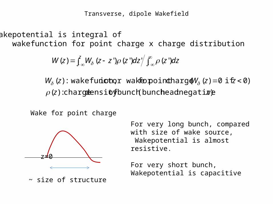
For very long bunch, compared with size of wake source, Wakepotential is almost resistive.
For very short bunch, Wakepotential is capacitive
Wakepotential is integral of wakefunction for point charge x charge distribution
')'(')'()'()( dzzdzzzzWzW
z
) negative :head(bunch bunch ofdensity charge :)(
)0 if 0)(( chargepoint for or wake ion, wakefunct:)(
zz
zzWzW
Transverse, dipole Wakefield
Transverse, dipole Wakefield
cdzzzzWzyezpz
y /')'()'()'()(
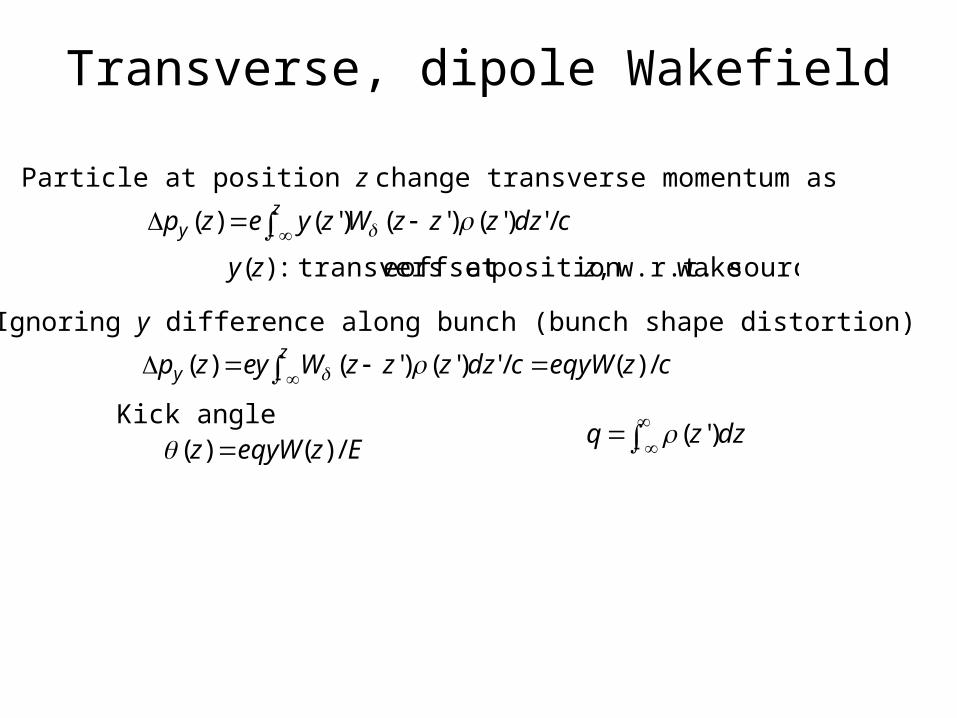
Particle at position z change transverse momentum as
source wake w.r.t.,position at offset e transvers:)( zzy
Ignoring y difference along bunch (bunch shape distortion)
czeqyWcdzzzzWeyzpz
y /)(/')'()'()(
')'( dzzq
EzeqyWz /)()( Kick angle
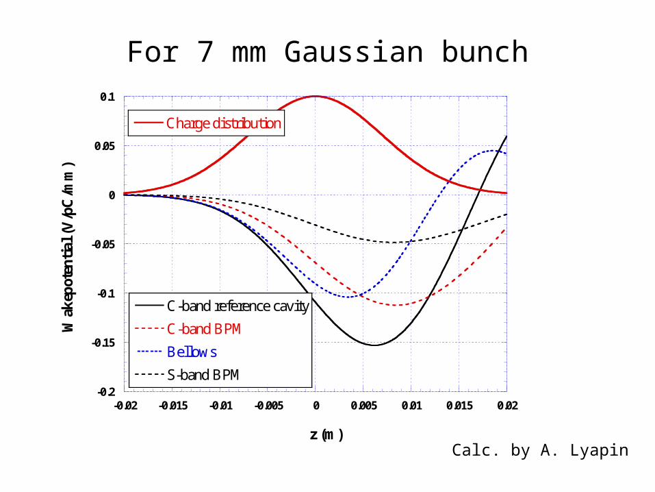
For 7 mm Gaussian bunch
Calc. by A. Lyapin
-0.2
-0.15
-0.1
-0.05
0
0.05
0.1
-0.02 -0.015 -0.01 -0.005 0 0.005 0.01 0.015 0.02
C-band reference cavity
C-band BPM
Bellows
S-band BPM
Charge distribution
Wak
epot
enti
al (
V/p
C/m
m)
z (m)
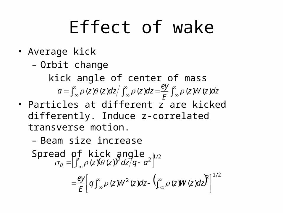
Effect of wake• Average kick– Orbit change kick angle of center of mass
• Particles at different z are kicked differently. Induce z-correlated transverse motion.– Beam size increaseSpread of kick angle
dzzWz
E
eydzzdzzza )()()()()(
2/122
2/122
)()()()(
)()(
dzzWzdzzWzqE
ey
aqdzzz
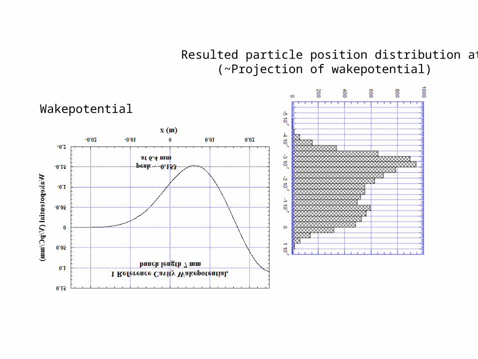
Wakepotential
Resulted particle position distribution at IP (~Projection of wakepotential)
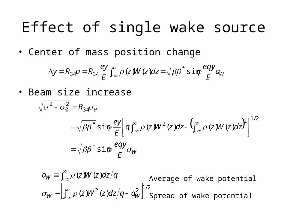
Effect of single wake source• Center of mass position change
• Beam size increase
WaE
eqydzzWz
E
eyRaRy sin)()( *
3434
WE
eqy
dzzWzdzzWzqE
ey
R
sin
)()()()(sin
*
2/122*
3420
2
2/122 )()(
)()(
WW
W
aqdzzWz
qdzzWza
Average of wake potential
Spread of wake potential
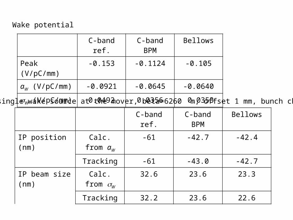
C-band ref. C-band BPM Bellows
Peak (V/pC/mm) -0.153 -0.1124 -0.105
aW (V/pC/mm) -0.0921 -0.0645 -0.0640
sW (V/pC/mm) 0.0492 0.0356 0.0353
C-band ref. C-band BPM Bellows
IP position (nm) Calc. from aW-61 -42.7 -42.4
Tracking -61 -43.0 -42.7
IP beam size (nm) Calc. from sW32.6 23.6 23.3
Tracking 32.2 23.6 22.6
Wake potential
Effect of single wake source at the mover, beta=6260 m, offset 1 mm, bunch charge 1 nC.
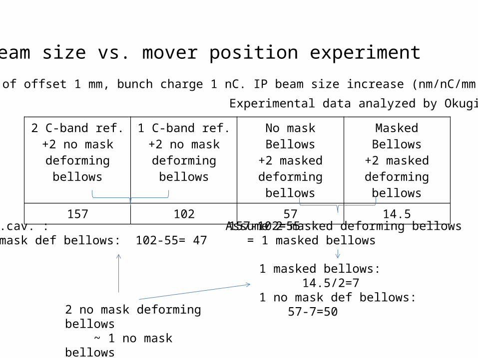
2 C-band ref.+2 no mask
deforming bellows
1 C-band ref.+2 no mask
deforming bellows
No mask Bellows+2 masked
deforming bellows
Masked Bellows+2 masked
deforming bellows157 102 57 14.5
IP beam size vs. mover position experiment
Effect of offset 1 mm, bunch charge 1 nC. IP beam size increase (nm/nC/mm)
1 ref.cav. : 157-102=552 no mask def bellows: 102-55= 47
1 masked bellows: 14.5/2=71 no mask def bellows: 57-7=50
Assume 2 masked deforming bellows = 1 masked bellows
2 no mask deforming bellows ~ 1 no mask bellows
Experimental data analyzed by Okugi
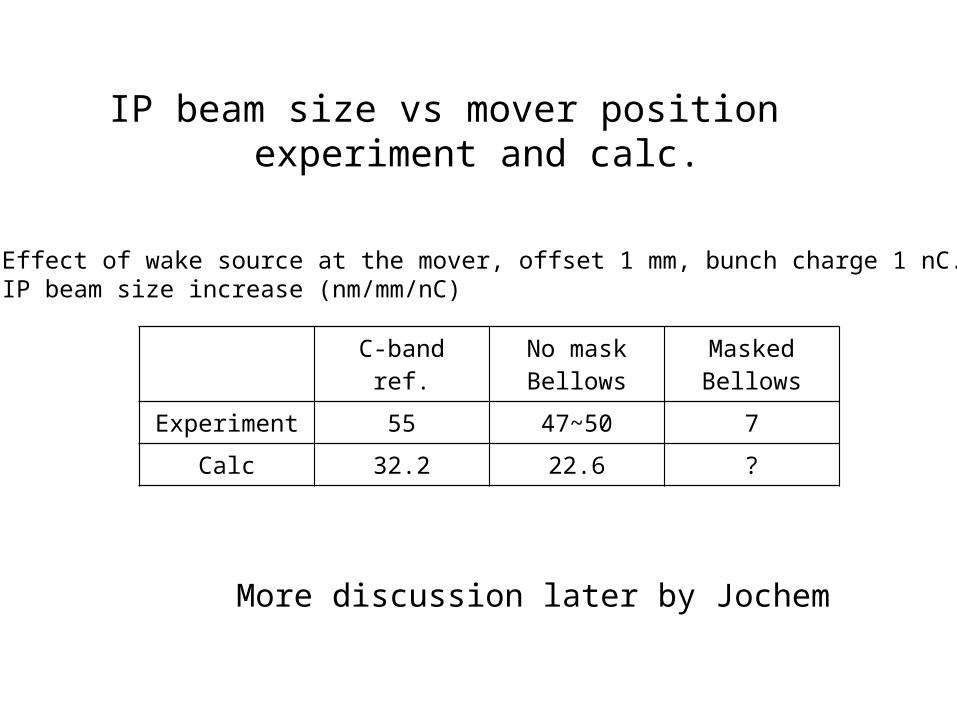
C-band ref. No mask Bellows
Masked Bellows
Experiment 55 47~50 7
Calc 32.2 22.6 ?
IP beam size vs mover position experiment and calc.
Effect of wake source at the mover, offset 1 mm, bunch charge 1 nC.IP beam size increase (nm/mm/nC)
More discussion later by Jochem
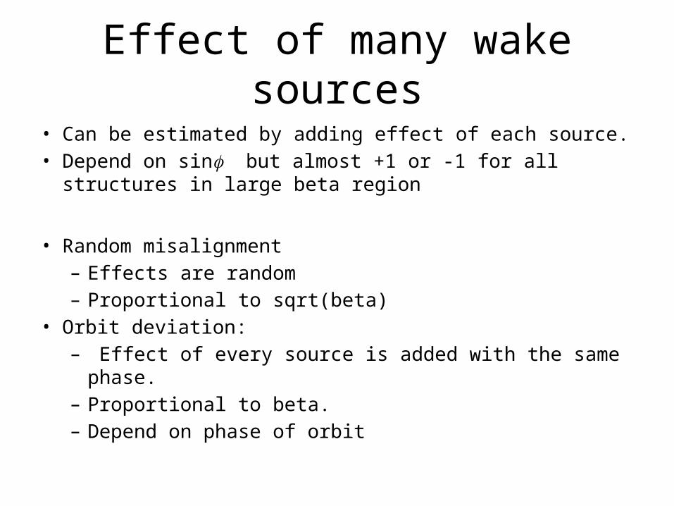
Effect of many wake sources
• Can be estimated by adding effect of each source.• Depend on sinf but almost +1 or -1 for all structures in large
beta region
• Random misalignment– Effects are random– Proportional to sqrt(beta)
• Orbit deviation:– Effect of every source is added with the same phase. – Proportional to beta.– Depend on phase of orbit
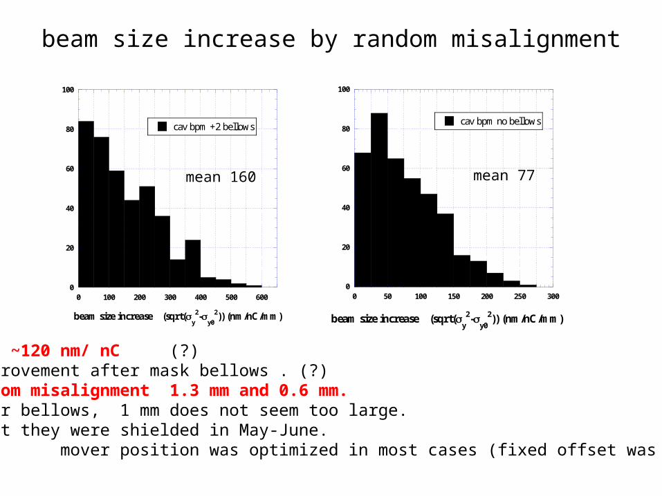
beam size increase by random misalignment
Experiment: ~120 nm/ nC (?)No clear improvement after mask bellows . (?) random misalignment 1.3 mm and 0.6 mm. For bellows, 1 mm does not seem too large. But they were shielded in May-June. mover position was optimized in most cases (fixed offset was compensated?).
0
20
40
60
80
100
0 100 200 300 400 500 600
cav bpm +2 bellows
beam size increase (sqrt(y
2-y0
2)) (nm/nC/mm)
mean 160
0
20
40
60
80
100
0 50 100 150 200 250 300
cav bpm no bellows
beam size increase (sqrt(y
2-y0
2)) (nm/nC/mm)
mean 77
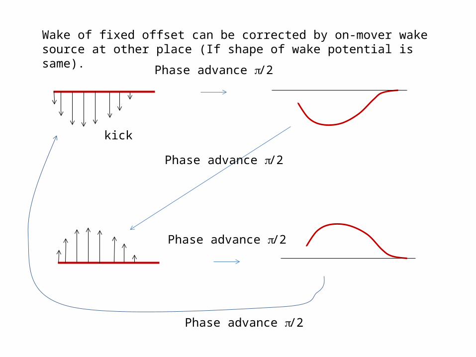
Phase advance p/2
kick
Phase advance p/2
Phase advance p/2
Phase advance p/2
Wake of fixed offset can be corrected by on-mover wake source at other place (If shape of wake potential is same).
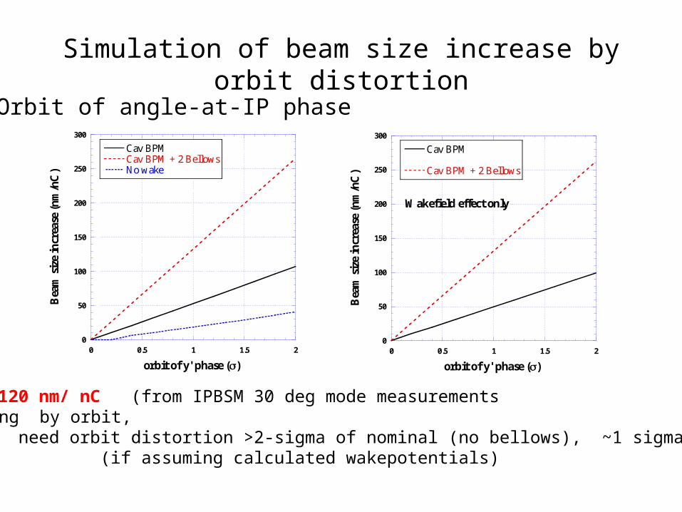
Simulation of beam size increase by orbit distortion
Orbit of angle-at-IP phase
0
50
100
150
200
250
300
0 0.5 1 1.5 2
Cav BPMCav BPM + 2 BellowsNo wake
Bea
m s
ize
incr
ease
(n
m/n
C)
orbit of y' phase ()
0
50
100
150
200
250
300
0 0.5 1 1.5 2
Wakefield effect only
Cav BPM
Cav BPM + 2 Bellows
Bea
m s
ize
incr
ease
(n
m/n
C)
orbit of y' phase ()
Experiment: ~120 nm/ nC (from IPBSM 30 deg mode measurements For explaining by orbit, need orbit distortion >2-sigma of nominal (no bellows), ~1 sigma (with bellows) (if assuming calculated wakepotentials)
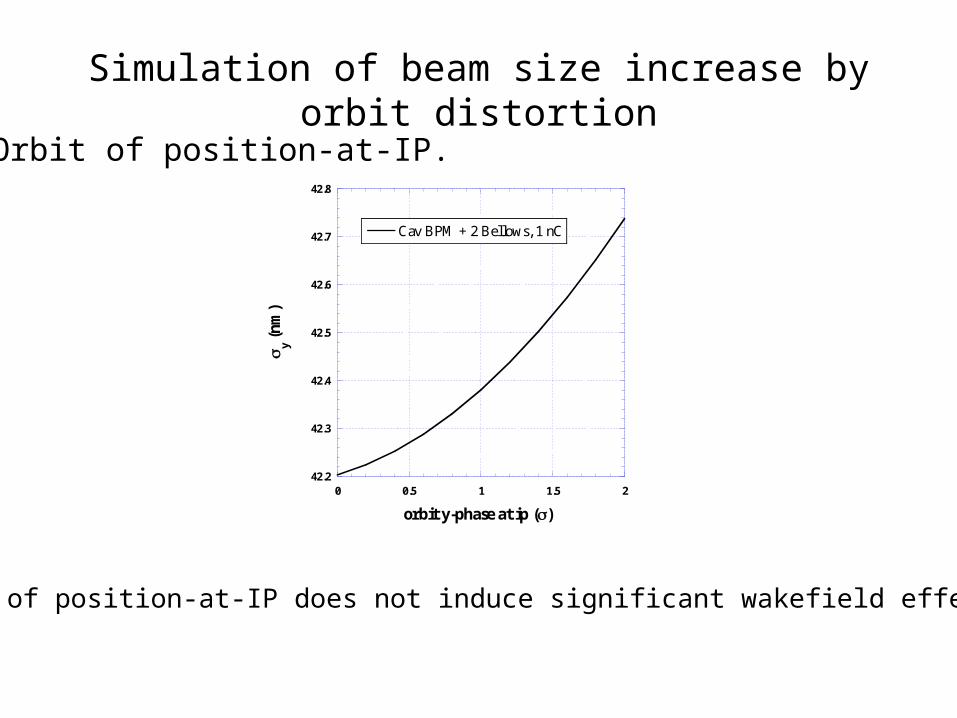
Simulation of beam size increase by orbit distortion
Orbit of position-at-IP.
42.2
42.3
42.4
42.5
42.6
42.7
42.8
0 0.5 1 1.5 2
Cav BPM + 2 Bellows, 1 nC
y (n
m)
orbit y-phase at ip ()
Orbit of position-at-IP does not induce significant wakefield effect.
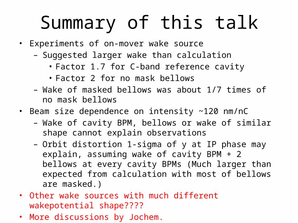
Summary of this talk• Experiments of on-mover wake source
– Suggested larger wake than calculation• Factor 1.7 for C-band reference cavity• Factor 2 for no mask bellows
– Wake of masked bellows was about 1/7 times of no mask bellows
• Beam size dependence on intensity ~120 nm/nC– Wake of cavity BPM, bellows or wake of similar shape
cannot explain observations– Orbit distortion 1-sigma of y at IP phase may explain,
assuming wake of cavity BPM + 2 bellows at every cavity BPMs (Much larger than expected from calculation with most of bellows are masked.)
• Other wake sources with much different wakepotential shape????
• More discussions by Jochem.