wales for replacement doors and windows · pdf file2 wales for replacement doors and windows...
TRANSCRIPT
1
2
Wales for Replacement Doors and Windows
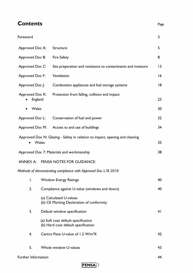
Contents Page
Foreword 3
Approved Doc A: Structure 5
Approved Doc B: Fire Safety 8
Approved Doc C: Site preparation and resistance to contaminants and moisture 13
Approved Doc F: Ventilation 16
Approved Doc J: Combustion appliances and fuel storage systems 18
Approved Doc K: Protection from falling, collision and impact
England 23
Wales 30
Approved Doc L: Conservation of fuel and power 32
Approved Doc M: Access to and use of buildings 34
Approved Doc N: Glazing - Safety in relation to impact, opening and cleaning
Wales 35
Approved Doc 7: Materials and workmanship 38
ANNEX A: FENSA NOTES FOR GUIDANCE:
Methods of demonstrating compliance with Approved Doc L1B 2010:
1. Window Energy Ratings 40
2. Compliance against U-value (windows and doors) 40
(a) Calculated U-values
(b) CE Marking Declaration of conformity
3. Default window specification 41
(a) Soft coat default specification
(b) Hard coat default specification
4. Centre Pane U-value of 1.2 W/m2K 42
5. Whole window U-values 43
Further Information 44
3
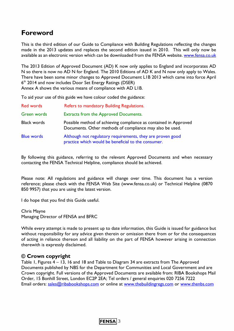
Foreword
This is the third edition of our Guide to Compliance with Building Regulations reflecting the changes
made in the 2013 updates and replaces the second edition issued in 2010. This will only now be
available as an electronic version which can be downloaded from the FENSA website. www.fensa.co.uk
The 2013 Edition of Approved Document (AD) K now only applies to England and incorporates AD
N so there is now no AD N for England. The 2010 Editions of AD K and N now only apply to Wales.
There have been some minor changes to Approved Document L1B 2013 which came into force April
6th 2014 and now includes Door Set Energy Ratings (DSER)
Annex A shows the various means of compliance with AD L1B.
To aid your use of this guide we have colour coded the guidance:
Red words Refers to mandatory Building Regulations.
Green words Extracts from the Approved Documents.
Black words Possible method of achieving compliance as contained in Approved
Documents. Other methods of compliance may also be used.
Blue words Although not regulatory requirements, they are proven good
practice which would be beneficial to the consumer.
By following this guidance, referring to the relevant Approved Documents and when necessary contacting the FENSA Technical Helpline, compliance should be achieved.
Please note: All regulations and guidance will change over time. This document has a version
reference; please check with the FENSA Web Site (www.fensa.co.uk) or Technical Helpline (0870
850 9957) that you are using the latest version.
I do hope that you find this Guide useful.
Chris Mayne
Managing Director of FENSA and BFRC
While every attempt is made to present up to date information, this Guide is issued for guidance but
without responsibility for any advice given therein or omission there from or for the consequences
of acting in reliance thereon and all liability on the part of FENSA however arising in connection
therewith is expressly disclaimed.
© Crown copyright Table 1, Figures 4 – 13, 16 and 18 and Table to Diagram 34 are extracts from The Approved
Documents published by NBS for the Department for Communities and Local Government and are
Crown copyright. Full versions of the Approved Documents are available from: RIBA Bookshops Mail
Order, 15 Bonhill Street, London EC2P 2EA; Tel orders / general enquiries 020 7256 7222
Email orders: [email protected] or online at www.thebuildingregs.com or www.thenbs.com
4
The Building Regulations exist to ensure the health and safety of people in and
around all types of buildings. They also provide for energy conservation, access to
and use of buildings.
To assist with understanding, DCLG (Department for Communities and Local
Government), the Government department with responsibility for Building
Regulations, in England, produces an excellent guide written in clear English that will
help in understanding why the system works in the way it does.
As from January 2012, any new Approved Documents issued by DCLG only apply in England.
For Wales the existing Approved Documents for England and Wales will apply until the Welsh Assembly issues its own version of the Approved Document.
Hard copies for England are free from the DCLG or it can be downloaded free from their website
at:
http://www.planningportal.gov.uk/buildingregulations/approveddocuments/
Hard copies for Wales are free from the DCLG or it can be downloaded free from their website at: http://wales.gov.uk/topics/planning/buildingregs/publications/;jsessionid=378EEF52778AE6B34E3AFA696CD271E9?lang=en
NOTE: Until DCLG issues updates to all the Approved Documents there will be conflicting
references. It is the intention of this guidance to reduce the risk of confusion and to that end some
editorial changes may be made to the extracts of certain Approved Documents in relation to
references to England and Wales.
There are many ways in which compliance with the Building Regulations can be achieved. DCLG
produces a series of guidelines that demonstrate some of the more straightforward ways to achieve
compliance with the Regulations. These guidelines are referred to as Approved Documents.
FENSA enables companies that install replacement windows and doors to self certify compliance to the Building Regulations for England and Wales under the Competent Person
Scheme.
The Building Regulation Approved Documents
Where windows and doors are to be replaced (but not where they are to be repaired only, as repair
work does not fall within the definition of building work) the replacement work should comply with
the requirements of Approved Documents L1B and K in England and Approved Documents L1B and
N in Wales. In addition, after the work has been completed, the building should not have a lesser level
of compliance with the other applicable parts of Schedule 1of the Building Regulations.
Summary: Replacement doors and windows should always comply fully with the requirements of:
England:
Approved Document L1B – Conservation of fuel & power in existing dwellings
Approved Document K 2013 – Protection from falling collision and impact
Wales:
Approved Document L1B – Conservation of fuel & power in existing dwellings
Approved Document N – Glazing – Protection against impact
However, for all other applicable parts of the Building Regulations the windows or doors should
either comply fully with the requirements of the Approved Documents or, if the item being replaced
does not already fully comply, the replacement item should NOT make the non-compliance worse.
5
Approved Document A: Structure
Requirement A1
The building shall be constructed so that the combined dead, imposed and wind loads are sustained and transmitted by it to
the ground:
a) Safely; and
b) Without causing such deflection or deformation of any part
of the building, or such movement of the ground, as will
impair the stability of any part of another building.
With regard to windows and doors, Approved Document A applies to bay windows and other
windows that are load bearing, e.g. where adequate means of support have not been used. When
replacing windows and doors it is vital that the integrity of any existing structural support is not
compromised. The supplier of the framing material may be able to offer technical advice.
It is important to note that in situations where uncertainty exists, e.g. when using new materials or construction methods, the services of a structural engineer or other competent person should be
employed.
Best Practice Note
Adequate means of support It is essential to maintain the integrity of the building.
The necessity for an adequate means of support is dependent on the design of the structure. However, even if
no such support is evident the Installation Company is responsible for assessing if one should be installed due
to potential damage to the buildings structural integrity. If this additional work is required, the customer can be
given the option to have it fitted by the Installation Company or independently.
The Installation Company cannot avoid the issue on the grounds that because there is no means of support over
the existing window there is no requirement to fit one over the new. It is strongly recommended that the need
is thoroughly investigated before work commences.
A disclaimer issued by the customer is an unacceptable practice and is likely to incur a FENSA non-conformity.
Every effort should be made at the time of survey to determine if an adequate means of support is either fitted
or required. There will be instances where windows being renewed are replacements of the original load bearing
timber frames but did not have the necessary means of support fitted. The construction material of the original
windows should be established if possible as this may help in determining the requirement.
If the surveyor cannot establish this either way, both the customer and installation team should be notified as
to the possibility or should seek the advice of a structural engineer.
In the worst case the installation team may only recognise the need after the removal of the existing frame. It is
entirely the installing company’s responsibility to inform the customer immediately advising that an adequate
means of support must be installed before the replacement window or door can be fitted. Clearly a situation to
be avoided especially as this will incur additional time and cost to the customer not written into the original
contract.
6
If a means of support is required, a separate contract and costing can be raised or it can be
incorporated within the window contract as a variation incurring additional cost. Although the
financial outlay of any support is the responsibility of the customer, the cost of any retrospective
remedial work required due to the omission of a required means of support would likely fall upon
the installation company e.g.
removal and safe storage of window to facilitate fitting of the means of support
making good any resultant damage to the fabric of the building
refitting of window
It should be noted that if, after the completion of an installation and the issuing of the FENSA
certificate, it can be established that an adequate means of support was not fitted where
needed, a retrospective non-conformity will be levied against the installation company even if
weeks, months or years have elapsed which will likely incur significant cost.
Removal of bay windows
In order to maintain the structural integrity when replacing a bay window, it is essential that temporary supports
such as adjustable steel props are used. It is important to ensure that the walls, floors or beams that may be
affected by the window replacement are adequately supported prior to removing the windows. Care should be
taken to protect internal ceiling and floor finishes at support bearing points. The sequence of removal of the windows in a two storey bay should ensure that unnecessary damage to the lower bay construction does not
occur and structural stability is not impaired. It is important that the structure is always adequately supported.
After supporting the bay structure, the windows should be removed carefully, ensuring that the minimum of
damage is caused to reveals, plaster, finishes and trims.
It is recommended that structural mullions are removed one at a time, and that both the temporary supports
and the pre-existing structure are closely monitored for any signs of settlement.
Depending upon the design of the structure at the head of the bay window, it may be
necessary to leave the head of the frame in position providing that there is no rot present. If the condition of
the aperture or the damp proof coarse (DPC) is not considered to be fit for purpose, or does not correspond
with that described by the surveyor, the installer should refer back to the surveyor or the company for
agreement to the proposed solution.
Installation of the replacement window assembly should not start until any defects in the structure have been
rectified. The assembly of the bay window should follow the product designer’s recommendations.
Care should be taken to ensure that no applied loads are carried by the individual segments of the window.
Bearing plates should be used on bay poles when loads are transferred from or to masonry or timber. Where
there is no danger of the bay pole damaging the fabric of the building with which it comes into contact, bearing
plates are not necessarily required e.g. where the bay pole bears directly onto a steel joist.
Care should be taken to ensure that the loads are transferred correctly from and to the structure of the building
and the bay pole assembly. This is achieved either by having the bay pole pass through the sill, or by using a sill
which is reinforced strongly enough to transfer the applied loads.
Bow Bay Replacements
It is recommended that the structure of a Bow Bay Replacement should be constructed in such a way as to
provide adequate means of support to a flat roof setup. This will take into account any loads imposed by a heavy
snow fall which could otherwise compromise the structure.
Ensure that exposed areas e.g. sills, external canopies or roofs are adequately insulated as this could incur a non-conformity against AD L when inspected.
7
Note 1: If a structural opening is to be made wider, Local Authority consent is required.
This is outside the scope of FENSA registration and should be referred to Local Authority
Building Control.
Note 2: If the existing structural apertures are found to be unsound prior to the replacement of any windows and/or doors, work should be carried out before hand to
ensure the stability of the building e.g. the soldier course above an existing window may
require an adequate means of support.
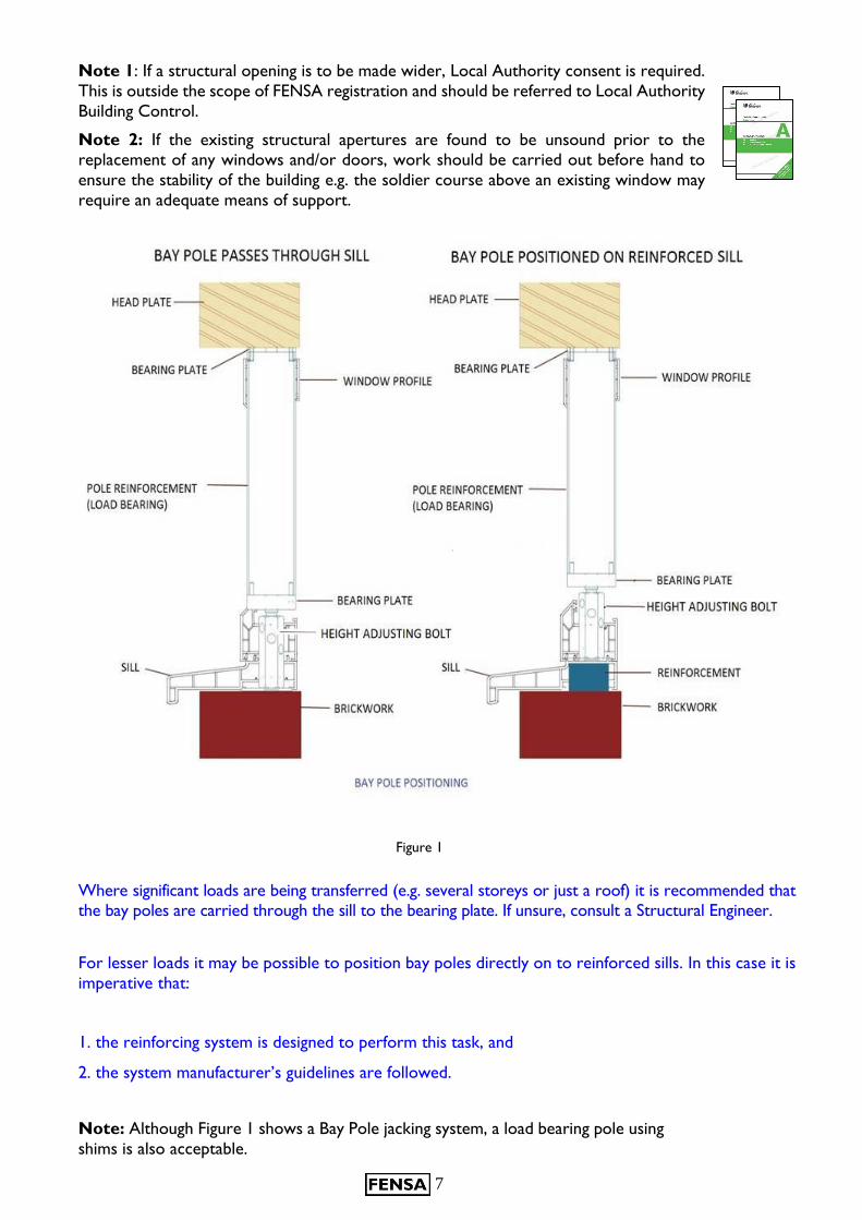
Where significant loads are being transferred (e.g. several storeys or just a roof) it is recommended that the bay poles are carried through the sill to the bearing plate. If unsure, consult a Structural Engineer.
For lesser loads it may be possible to position bay poles directly on to reinforced sills. In this case it is
imperative that:
1. the reinforcing system is designed to perform this task, and
2. the system manufacturer’s guidelines are followed.
Note: Although Figure 1 shows a Bay Pole jacking system, a load bearing pole using
shims is also acceptable.
Figure 1
8
Approved Document B: Fire Safety
Requirement B1
The building shall be designed and constructed so that there are
appropriate provisions for the early warning of fire and appropriate
means of escape in case of fire from the building to a place of safety
outside the building capable of being safely and effectively used at all
material times.
Approved Document B1 states:
Provision for escape from the ground storey
2.3. Except for kitchens all habitable rooms in the ground storey should either:
a) open directly onto a hall leading to the entrance or other suitable exit; or
b) be provided with a window (or door) which complies with paragraph 2.8.
Provision for escape from upper floors not more than 4.5 metres above ground level
2.4. Except for kitchens, all habitable rooms in the upper storey(s) of a dwellinghouse served by only one stair should be provided with:
a. a window (or external door) which complies with paragraph 2.8; or
b. direct access to a protected stairway (as described in 2.6 (a) or (b).
Emergency egress windows and external doors
2.8. Any window provided for emergency egress purposes and any external door provided for escape
should comply with the following conditions:
a) The window should have an unobstructed openable area that is at least 0.33m2 and at least
450mm high and 450mm wide (the route through the window may be at an angle rather than straight
through). The bottom of the openable area should be no more than 1100mm above the floor.
Note 1: Approved Document K Protection from falling, collision and impact specifies a minimum guarding height of 800mm, except in the case of a window in a roof where the bottom of the opening may be 600mm above the floor.
Note 2: Locks (with or without removable keys) and stays may be fitted to egress windows, subject
to the stay being fitted with a release catch, which may be child resistant.
Note 3: Windows should be designed such that they will remain in the open position without needing
to be held in position by the person during their escape.
9
Work on existing houses
2.19. Where windows are to be replaced (but not where they are to be repaired only, as repair work to windows does not fall within the definition of building work) the
replacement work should comply with the requirements of Parts L and N of Schedule 1. In
addition, the building should not have a lesser level of compliance, after the work has been
completed, with other applicable parts of Schedule 1.
Note: Please refer to summary on page 3 in relation to changes in applicable Approved Documents.
For the purposes of Part B1, where a window is located such that, in a new dwellinghouse, an escape window would be necessary and the window is of sufficient size that it could be used for the purposes
of escape then:
a. the replacement window opening should be sized to provide at least the same potential for escape as the window it replaces; or
b. where the original window is larger than necessary for the purposes of escape, the window opening could be reduced down to the minimum specified in paragraph 2.8.
Summary:
A fire escape window is required on the ground floor in any habitable room that does not open onto
a hall leading directly to an exit door e.g. an inner room.
A fire escape window is required on upper floors not more than 4.5m above ground level in
every habitable room (unless the room has direct access to a “protected stairway”). This is usually the
case for the upstairs of a conventional two-storey dwelling.
A habitable room does not include a kitchen or a bathroom.
Upper floors more than 4.5m above ground level should be accessed by a “protected stairway”
or an alternative escape route and therefore fire escape windows are not required.
There is no requirement to have more than one escape window in a room.
A fire escape window should have an unobstructed openable area that is at least 0.33m² and at least 450mm high or 450mm wide. If one of the dimensions is at the 450mm minimum then the other
dimension will need to be at least 734mm to achieve 0.33m². The route through the window may be
at an angle rather than straight through.
The bottom of the openable area should be no more than 1100mm above the floor.
If the outgoing window meets the minimum openable area size of 0.33m² and 450mm dimension, then
the replacement should meet these minimum requirements however, if the outgoing openable area
exceeds the minimum requirements, there is no obligation for the new window to meet this larger
size, as long as it meets the minimum requirement of 0.33m² and 450mm. Similarly, if the openable area
complies by being less than 1100mm above floor level then the replacement should also comply by
being less than 1100mm, but there is no obligation for it to be any lower than 1100mm above floor
level even if the outgoing window is lower.
If the outgoing window does not meet the minimum openable area requirements, then the
replacement window does not have to meet them, but the area, minimum dimension and height above
floor level should not be made worse than the outgoing window.
10
Best Practice Notes
Replacement window hardware
In all windows identified as egress, suitable hardware should be installed to maximise the means of escape opportunity e.g. egress hinges and non-key locking handles.
Note: Although the Approved Document allows for both keyed and non-keyed locking handles, it is
recommended that the non-key option is used.
Smoke Detectors Although it is not the responsibility of the replacement window company, every opportunity should be
taken to advise the householder to have adequate working smoke detectors throughout the property
to give early warning of fire.
Reducing Compliance
Although it is permissible to reduce compliance to the minimum required by Approved Document B, it
is recommended that maximum escape opportunity is retained wherever possible, for example by
retaining multiple escape windows in a room, particularly if they are on different elevations.
Non Compliance
If a replacement egress window cannot meet the minimum size requirements as defined within
paragraph 2.8 of Approved Document B1 and also the proposed replacement can only provide a
smaller egress size than the existing, refer to Local Authority Building Control who might apply discretion.
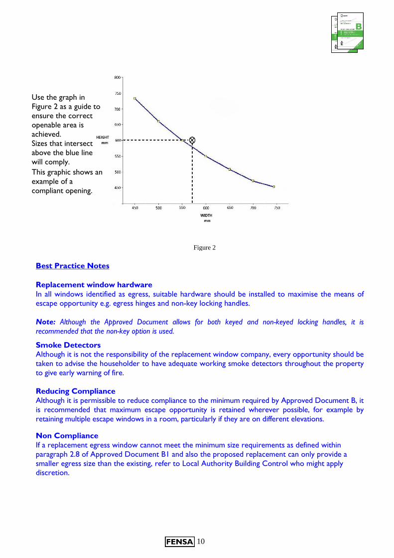
Figure 2
Use the graph in
Figure 2 as a guide to
ensure the correct
openable area is
achieved.
Sizes that intersect
above the blue line
will comply.
This graphic shows an example of a
compliant opening.
11
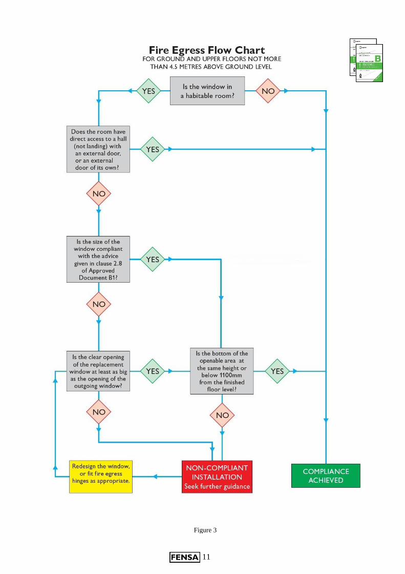
Figure 3
12
Approved Document B3 states:
Internal fire spread (structure) B3. (1) The building shall be designed and constructed so that, in the event of fire, its
stability will be maintained for a reasonable period.
(2) A wall common to two or more buildings shall be designed and constructed so that it
adequately resists the spread of fire between those buildings. For the purposes of this
sub-paragraph a house in a terrace and a semi-detached house are each to be treated as a
separate building.
(3) Where reasonably necessary to inhibit the spread of fire within the building, measures
shall be taken, to an extent appropriate to the size and intended use of the building,
comprising either or both of the following:
(a) sub-division of the building with fire-resisting construction;
(b) installation of suitable automatic fire suppression systems.
(4) The building shall be designed and constructed so that the unseen spread of fire and
smoke within concealed spaces in its structure and fabric is inhibited.
Particular care must be taken when replacing windows and doors within a timber framed building.
In most cases there will be a fire break between the window frame and cavity within the timber structure. If there is no fire break present one must be in place before the replacement window or door is fitted
This fire break must be installed without exception in order to maintain the fire suppression properties as laid down in the Approved Document B3 (4)
13
Approved Document C:
Site preparation and resistance
to contaminants and moisture
Requirement C2
The floors, walls and roofs of the building shall adequately
protect the building and people who use the building from
harmful effects caused by:
a. Ground moisture
b. Precipitation
c. Interstitial and surface condensation
d. Spillage of water from or associated with sanitary fittings or fixed appliances
Approved Document C states:
JOINT BETWEEN DOORS AND WINDOWS
5.29. The joint between walls and door and window frames should:
a. resist the penetration of precipitation to the inside of the building; and
b. not be damaged by precipitation and not permit precipitation to reach any part of the building
which would be damaged by it.
5.30. Damp-proof courses should be provided to direct moisture to the outside:
a. where downward flow of moisture would be interrupted at an obstruction e.g. at an adequate
means of support;
b. where sill elements, including joints, do not form a complete barrier to the transfer of
precipitation, e.g. under openings, windows and doors;
c. where reveals, including joints do not form a complete barrier to the transfer of rain and
snow, e.g. at openings, windows and doors.
5.31. In some cases the width of the cavity due to thermal insulation and the 50mm clearance for
drainage may be such that the window frame is not wide enough to completely cover the cavity closer.
The reveal may need to be lined with plasterboard, dry lining, a support system or a thermal backing
board. Direct plastering of the reveal should only be used with a backing of expanded metal lathe or
similar.
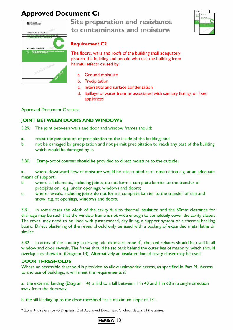
5.32. In areas of the country in driving rain exposure zone 4*, checked rebates should be used in all
window and door reveals. The frame should be set back behind the outer leaf of masonry, which should
overlap it as shown in (Diagram 13). Alternatively an insulated finned cavity closer may be used.
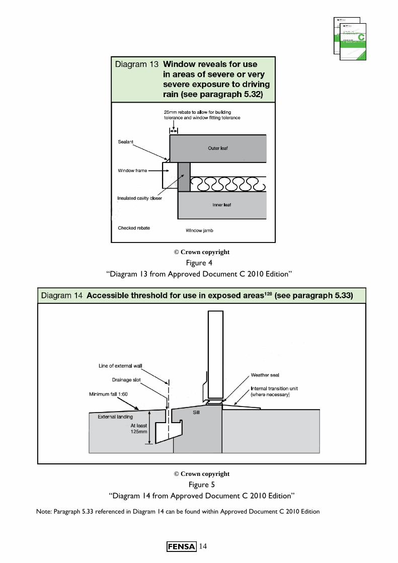
DOOR THRESHOLDS
Where an accessible threshold is provided to allow unimpeded access, as specified in Part M, Access
to and use of buildings, it will meet the requirements if:
a. the external landing (Diagram 14) is laid to a fall between 1 in 40 and 1 in 60 in a single direction
away from the doorway;
b. the sill leading up to the door threshold has a maximum slope of 15o.
* Zone 4 is reference to Diagram 12 of Approved Document C which details all the zones.
14
© Crown copyright
© Crown copyright
Note: Paragraph 5.33 referenced in Diagram 14 can be found within Approved Document C 2010 Edition
Figure 4
“Diagram 13 from Approved Document C 2010 Edition”
Figure 5
“Diagram 14 from Approved Document C 2010 Edition”
15
Summary:
Windows: When existing windows are removed from a cavity wall, the vertical Damp
Proof Coarse (DPC) or cavity closer should be inspected to ensure it is complete and un-
damaged. Remedial works to ensure compliance should be completed prior to the
installation of window.
When existing windows are removed from a cavity wall, the horizontal cavity, DPC or cavity closer at
the base of the window should be inspected to ensure moisture will not penetrate from the external
skin of the wall to the inner skin of the wall. Remedial works to ensure compliance should be completed
prior to the installation of window.
When existing windows are removed from a wall built with a checked rebate, the vertical DPC or cavity
closer should be inspected to ensure it is complete and un-damaged. Remedial works to ensure
compliance should be completed prior to the installation of the window. Windows should be re-fitted
with a check rebate to ensure compliance with Part C.
Windows should be installed on a bed of sealant across the sill and beads of sealant applied vertically to
the DPC or cavity closer and horizontally across the head of the window to form a seal between the
rear of the window and the wall. Either insulation of suitable backing materials such as closed cell foam
roll should be used in the gap between the window and wall to ensure the external sealant applied
pressure to the frame and wall when applied. Suitable external sealant should be applied to cover and
form a water resistant joint between the frame and wall.
If the new window if fitted into a sub-frame, end sealing of the sill between the frame and sub-sill is
essential to prevent water egress.
Doors: When the existing door is removed, confirm the type of sill detail fitted, this will either be a
conventional sill or an accessible threshold sill.
If a conventional sill is fitted, the DPC and vertical DPC should be inspected for damage and if necessary
repaired or replaced prior to the installation of the new door. Where a door with accessible threshold
is removed, the original method of installation needs to be determined (e.g. directly onto a concrete sill
with a DPC wrapped between the threshold and sill, on a timber sill fitted below finished floor level
etc.) and the water tightness of the system confirmed.
If a conventional sill is being installed, the door should be fitted in a similar way as described above for
windows.
If an accessible (low) threshold is being installed into an opening that originally had an accessible
threshold fitted, the door should be installed in the same manner as the original door was fitted with a
DPC between the bottom of the threshold and the stone or timber sill with a sealant between the
threshold and DPC.
If an accessible threshold is being installed where a conventional sill was originally fitted, some additional
works may be necessary to correct the height of the sill below the door and to ensure surface water is
directed away from the door to a suitable drainage channel or run-off.
Details of accessible threshold designs can be obtained from The Stationary Office – Accessible
thresholds for new housing or BRE guidance IP17/01.
Doors should be sealed externally as described for windows above but care should be taken to ensure
drainage holes in the external face of the threshold are not blocked.
16
Approved Document F:
Ventilation
Requirement F1
There shall be adequate means of ventilation provided for people in the
building.
For new dwellings, a target of four air changes per hour is required to ensure suitable ventilation.
The installation of replacement windows should ideally achieve the requirements for new buildings.
However, if this is not possible the replacement windows should not make the existing capability
worse.
There are two different types of ventilation that are required within a building.
1) Purge ventilation
Purge ventilation is required to remove high levels of pollutants and water vapour. It may also improve thermal comfort and reduce overheating during the summer.
Requirements for purge ventilation via windows
For hinged or pivot windows that open 30 degrees or more, or for sliding sash windows, the area
of the opening should be at least 1/20th of the floor area of the room.
For a hinged or pivot window that opens less than 30 degrees, the area of the opening should be
at least 1/10th of the floor area of the room.
Note 1: For this purpose the opening area of a hinged or pivot window can be taken as the
overall width x height of the opening sash.
Note 2: The opening areas for all windows in a room can be added together for the above purpose.
Note 3: It is good practice that any existing high level purge ventilation should be maintained.
For example, when replacing a vertical sliding sash window, it is strongly recommended that two
opening sashes (vertical slider or two top hung lights) or a tilt turn window are used. If a fixed top
light is used, a suitably sized trickle ventilator should be installed.
2) Background ventilation
It is important that the dwelling can constantly breathe - good indoor air quality is
important for health and also helps protect the fabric of the building from the harmful
effects of condensation and mould etc. Background ventilation helps to achieve this.
17
Requirements for background ventilation
Where the outgoing window provided background ventilation, the replacement window
should also provide background ventilation. It is acceptable for alternative high level
ventilation to be provided, e.g. high level air brick. Typically, background ventilation is
positioned at least 1.7 metres above finished floor level to avoid discomfort due to draughts.
Where trickle ventilators are used to provide background ventilation then the following performance
is required:- habitable rooms 5000 mm2 equivalent area. Kitchens, bathrooms and other wet room
areas require 2500 mm2 equivalent area.
If trickle ventilators are fitted in the window that is being replaced, then a trickle ventilator
should be fitted to the new window or an appropriately sized air brick fitted. (Two stage
locking handles are not acceptable as an alternative to trickle ventilators.)
If trickle ventilators are not fitted, but two-stage locking handles are fitted in the windows
being removed, then either:
a) trickle vents can be fitted as an alternative, or b) two-stage locking handles can be fitted or c) appropriate air-bricks can be fitted.
If no ventilation is provided in the windows being removed then a number of options are available to the consumer. Consideration should be given to the fitting of:
a) trickle vents, or b) two-stage locking handles, or c) air bricks
The key point is that the building work, once completed, should not have a worse level of compliance than before commencement of the work. Therefore the customer can, in these circumstances, opt
not to fit ventilators.
The provision of permanent ventilators for combustion appliances is a mandatory requirement as laid
out in Approved Document J. Seek advice from a Gas Safe registered engineer to establish the level of
required ventilation. See also Section J within this guidance.
Best Practice Notes
When specifying replacement windows the current level of ventilation in each room should be
assessed. If you consider that it is inadequate, advise the customer of the options available. Ensure that
whichever method is chosen it meets the necessary level of compliance.
Where the existing purge ventilation area is in excess of the requirements, although it is acceptable to
reduce this to the minimum level requirement in the Approved Document, consideration should be
given to retaining the existing level.
18
Approved Document J:
Combustion appliances and fuel
storage systems
Air supply
J1. Combustion appliances shall be so installed that there is an adequate
supply of air to them for combustion, to prevent overheating and for the
efficient working of any flue.
Discharge of products of combustion
J2. Combustion appliances shall have adequate provision for the discharge of products of combustion
to the outside air
Note: J1 and J2 apply only to fixed combustion appliances (excluding incinerators)
Air supply for combustion appliances
1.2 Combustion appliances require ventilation to supply them with air for combustion. Ventilation is
also required to ensure the proper operation of flues or, in the case of flueless appliances, to ensure
that the products of combustion are safely dispersed to the outside air. Installation of room-sealed
appliances or those with a directly connected ducted external air supply will minimise ventilation energy
losses from the room and the risk of cold draughts. In some cases, combustion appliances may also
require air for cooling control systems and/or to ensure that casings remain safe to touch (see Diagram
8 in Approved Document J). General guidance on where it may be necessary to install air vents for
these purposes is given below.
1.3 Air vent sizes, which are dependent upon the type of fuel burned, are given in Sections 2, 3 and 4
and are for one combustion appliance only. The air supply provisions will usually need to be increased
where a room contains more than one appliance (such as a kitchen containing an open-flued boiler and
an open-flued cooker).
Permanently open ventilation of rooms
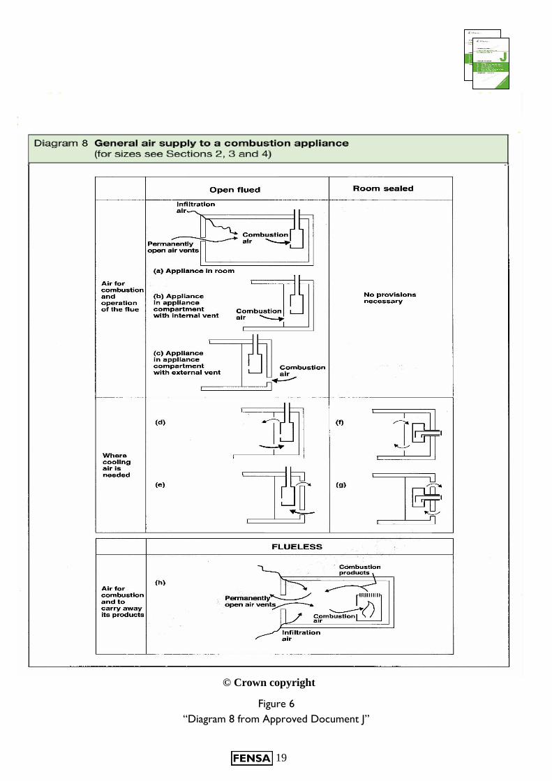
1.4 A room containing an open-flued appliance may need permanently open air vents. An open-flued
appliance should receive a certain amount of air from outside (‘combustion air’ in Diagram 8, Approved
Document J) dependent upon its type and rating. Infiltration through the building fabric may be sufficient
but for certain appliance ratings and forms of construction, permanent openings are necessary (see
Diagram 8 below).
19
Figure 6
“Diagram 8 from Approved Document J”
© Crown copyright

20
Approved Document J paragraphs 1.18 and 1.19 make provision for using ventilation which
satisfies the requirements for part F and J and states:
1.18. Rooms or spaces intended to contain open-flued combustion appliances may need permanent
ventilation to comply with Part J and adjustable ventilation to comply with Part F. Permanently open
air vents for combustion appliances can be accepted in place of some or all of the adjustable background
ventilation for health, dependent upon opening area and location. However adjustable vents installed
to meet the requirements of Part F cannot be used as substitutes for the ventilation openings needed
to comply with Part J unless they are fixed permanently open.
1.19. Rooms or spaces intended to contain flueless appliances may need: permanent ventilation and
purge ventilation (such as openable windows) to comply with Part J; and adjustable ventilation and
rapid ventilation to comply with Part F. Permanent ventilation provisions to comply with Part J may be
acceptable in place of adjustable ventilation provisions for Part F subject to the limitations described in
Paragraph 1.18. Openable elements installed for the rapid ventilation of rooms and other provisions
made for the rapid ventilation of kitchens, in order to comply with Part F, may be acceptable in place
of openable elements for the rapid ventilation of rooms or spaces containing flueless appliances.
Limitation on requirements
In accordance with regulation 8 of the Building Regulations, the requirements in Parts A to D, F to K
and N and P (except for paragraphs G2, H2 and J6) of Schedule 1 to the Building Regulations do not
require anything to be done except for the purpose of securing reasonable standards of health
and safety for persons in or about buildings (and any others who may be affected by buildings or
matters connected with buildings).
The replacement window should not make the ventilation requirements any worse for
any combustion appliance which is using permanently open vents installed through the window. If a
replacement window installer is not sure if a window vent is being used to ventilate a gas appliance, a
“Gas Safe” registered gas fitter should be consulted to provide advice.
Particular care should be taken when installing replacement windows in rooms with a gas cooker,
provision for a gas cooker or other flueless appliances such as water or space heaters.
In the case of a gas cooker (or provision for a gas cooker), the size of permanently open ventilation is
dependant on the volume of the room, if the room is below 5m3 free area of permanent ventilation is
10,000mm2, between 5m3 and 10m3, 5,000 mm2 (no permanent opening required if the room has a
door that opens directly to outside) and over 10 m3, no permanently open vent needed.
Instantaneous water heaters require the same permanently open ventilation but the volume limits are
under 10m3, between 10m3 and 20m3 and over 20 m3 respectively.
Space heaters installed in areas not classed as internal space, i.e.. a room which communicates with
several other rooms or spaces, e.g. a hallway or landing, requires permanently open ventilation of
10,000 mm2 plus 5,500 mm2 per kW input (net) in excess of 2.7kW (net).
Space heaters installed in an internal space, e.g. a lounge, requires permanently open ventilation of
10,000 mm2 plus 2,750mm2 per kW input (net) in excess of 5.4kW (net).
If there is any doubt regarding the amount and provision of permanently open ventilation, the issue
should be referred to a “Gas Safe” registered gas fitter to provide advice.
21
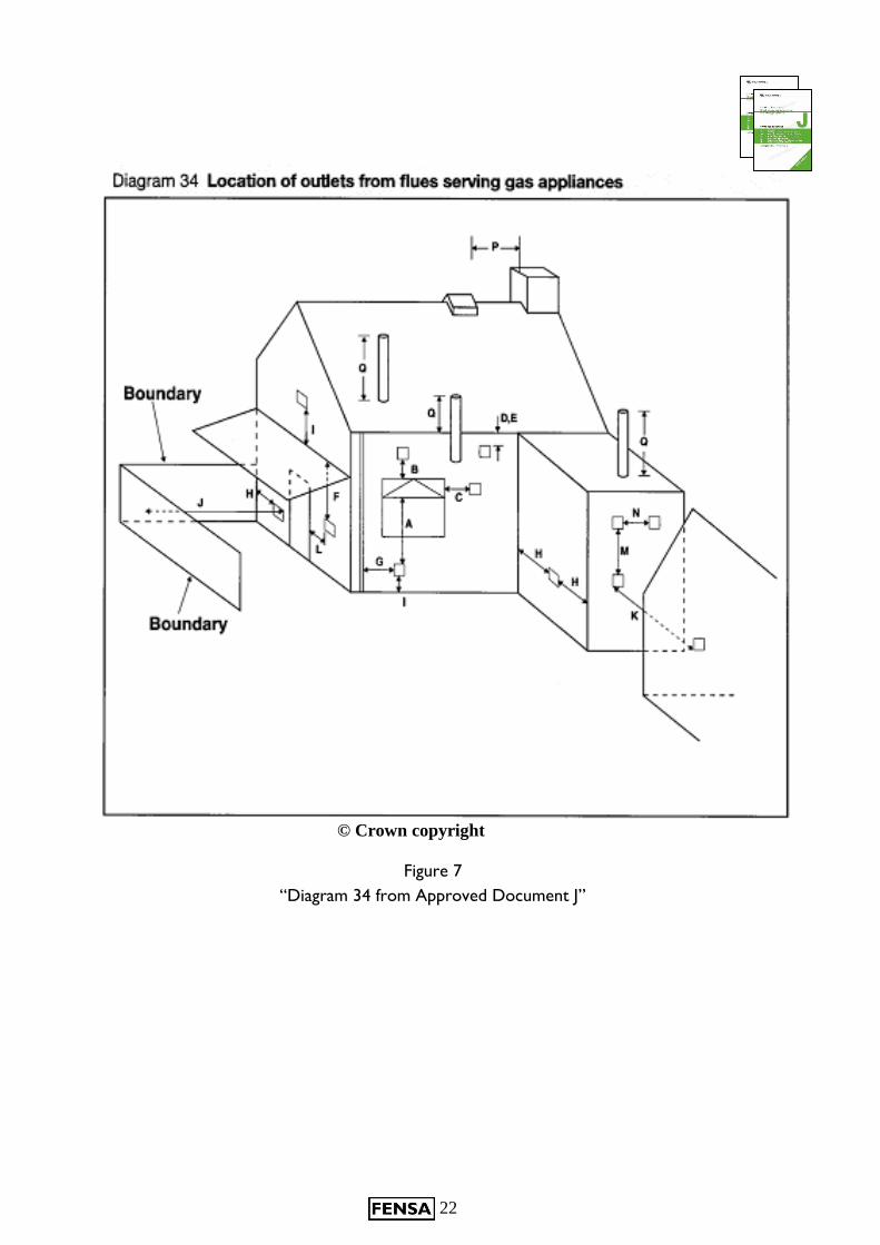
Outlets from flues
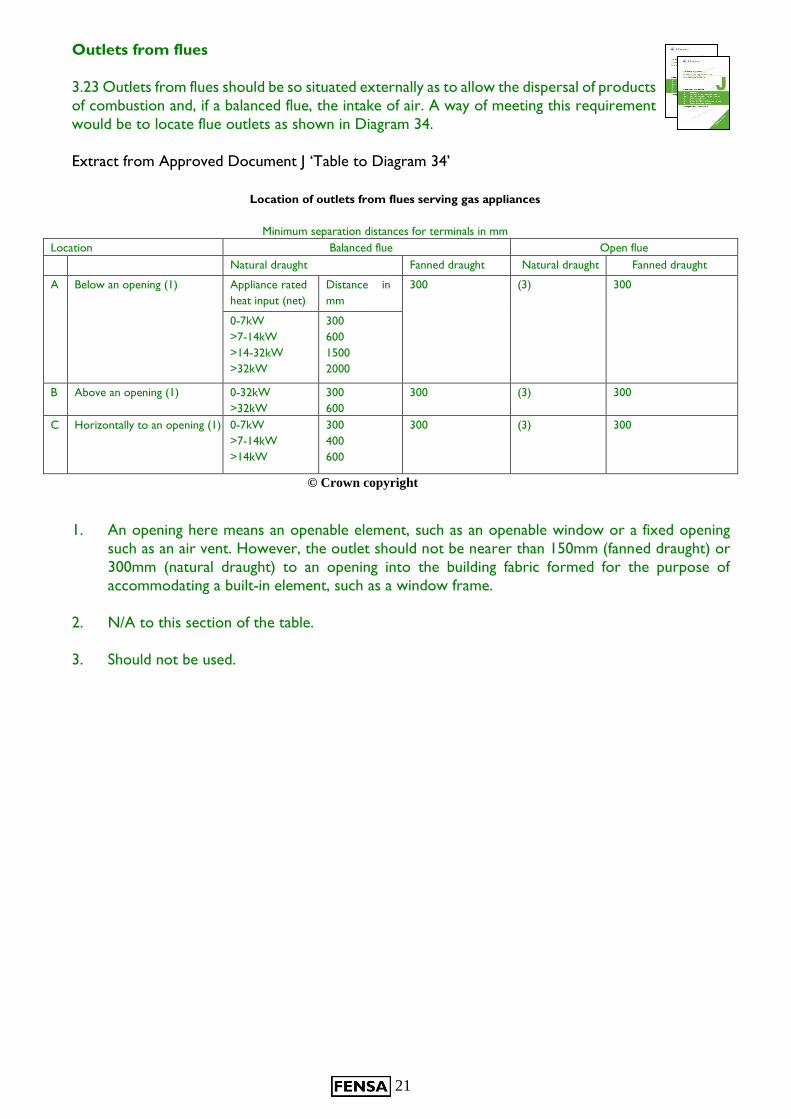
3.23 Outlets from flues should be so situated externally as to allow the dispersal of products
of combustion and, if a balanced flue, the intake of air. A way of meeting this requirement
would be to locate flue outlets as shown in Diagram 34.
Extract from Approved Document J ‘Table to Diagram 34’
Location of outlets from flues serving gas appliances
Minimum separation distances for terminals in mm
Location Balanced flue Open flue
Natural draught Fanned draught Natural draught Fanned draught
A Below an opening (1) Appliance rated
heat input (net)
Distance in
mm
300 (3) 300
0-7kW
>7-14kW
>14-32kW
>32kW
300
600
1500
2000
B Above an opening (1) 0-32kW
>32kW
300
600
300 (3) 300
C Horizontally to an opening (1) 0-7kW
>7-14kW
>14kW
300
400
600
300 (3) 300
© Crown copyright
1. An opening here means an openable element, such as an openable window or a fixed opening
such as an air vent. However, the outlet should not be nearer than 150mm (fanned draught) or
300mm (natural draught) to an opening into the building fabric formed for the purpose of
accommodating a built-in element, such as a window frame.
2. N/A to this section of the table.
3. Should not be used.
22
© Crown copyright
Figure 7
“Diagram 34 from Approved Document J”
23
Approved Document K: 2013
(England)
Protection from falling,
collision and impact
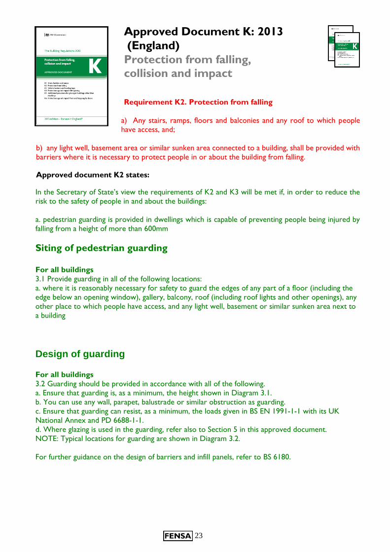
Requirement K2. Protection from falling
a) Any stairs, ramps, floors and balconies and any roof to which people
have access, and;
b) any light well, basement area or similar sunken area connected to a building, shall be provided with
barriers where it is necessary to protect people in or about the building from falling.
Approved document K2 states:
In the Secretary of State’s view the requirements of K2 and K3 will be met if, in order to reduce the
risk to the safety of people in and about the buildings:
a. pedestrian guarding is provided in dwellings which is capable of preventing people being injured by
falling from a height of more than 600mm
Siting of pedestrian guarding
For all buildings
3.1 Provide guarding in all of the following locations:
a. where it is reasonably necessary for safety to guard the edges of any part of a floor (including the
edge below an opening window), gallery, balcony, roof (including roof lights and other openings), any
other place to which people have access, and any light well, basement or similar sunken area next to
a building
Design of guarding For all buildings
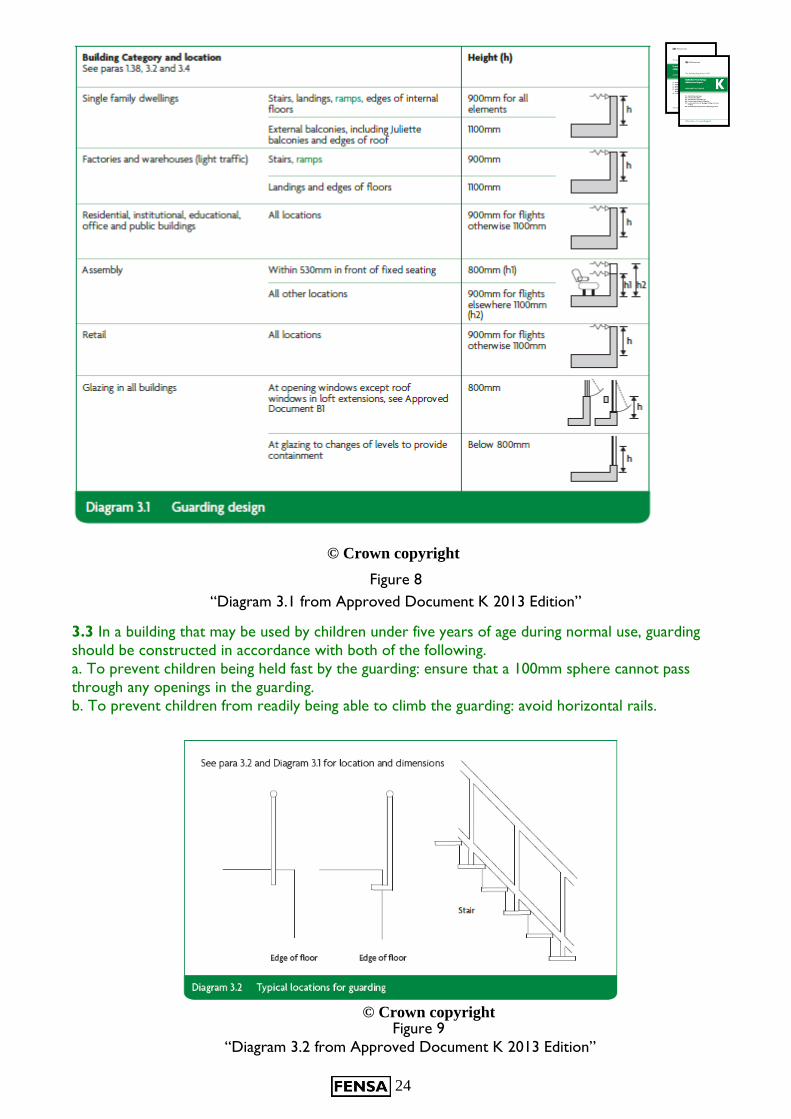
3.2 Guarding should be provided in accordance with all of the following.
a. Ensure that guarding is, as a minimum, the height shown in Diagram 3.1.
b. You can use any wall, parapet, balustrade or similar obstruction as guarding.
c. Ensure that guarding can resist, as a minimum, the loads given in BS EN 1991-1-1 with its UK
National Annex and PD 6688-1-1.
d. Where glazing is used in the guarding, refer also to Section 5 in this approved document.
NOTE: Typical locations for guarding are shown in Diagram 3.2.
For further guidance on the design of barriers and infill panels, refer to BS 6180.
24
3.3 In a building that may be used by children under five years of age during normal use, guarding
should be constructed in accordance with both of the following.
a. To prevent children being held fast by the guarding: ensure that a 100mm sphere cannot pass
through any openings in the guarding.
b. To prevent children from readily being able to climb the guarding: avoid horizontal rails.
© Crown copyright
Figure 9
“Diagram 3.2 from Approved Document K 2013 Edition”
© Crown copyright
Figure 8
“Diagram 3.1 from Approved Document K 2013 Edition”
25
Note 1: In areas where the window is situated above a fixture e.g. bath/shower
tray or window seat, the finished floor level is taken from the point on which is
stood or sat upon and not the floor level where the item has been affixed.
Note 2: Similarly the drop on stairway is measured from the height of the highest tread
within the span of the window.
Note 3: Finished floor level would be taken from the top of any floor furnishings that may or
may not be in place at the time of the survey. In some cases the ground level outside may vary
from inside the property. The smaller of the two dimensions should be used to determine if
the window is in a critical location.
It is important to note that any part of a glass area affected should meet the requirements in its entirety
and not just in the relevant section.
The Regulation applies to fixed glazing and opening lights less than 800mm above floor level, where the
floor (or stairs or landing) adjacent to a window is more than 600mm above the outside ground level.
It usually means that low-level opening lights should have restricted openers and all low-level glazing
should be sufficiently robust to resist likely impact.
Compliance can also be achieved by providing alternative guarding e.g. a guard rail or other fixed
barrier, which should cover the zone 800mm above the floor.
For replacement windows and doors the obligation is to make compliance no worse. A replacement
window with a qualifying low-level opening light should be fitted with a restrictor if the outgoing
window was fitted with one. If a new qualifying low-level opening light is introduced into a replacement
window then this should be restricted.
Any fixed glazing less than 800mm above floor level which acts as a barrier to prevent people falling
out should be replaced with glazing which meets the impact resistance requirements of BS 6262-4
taking into account Approved Document K for containment.
Approved Document K4 – Protection from impact with glazing. This has replaced A D N in England.
However, the requirements for safety glazing are unchanged.
Best Practice Note
It is recommended that opening restrictor devices are always fitted to opening lights less than 800mm
above floor level.
Reference should be made to K4 of Approved Document K
Note: Approved Document K (England) still refers to BS 6206 however, this standard has been withdrawn for glass. The Safe Breakage element has been replaced by EN 12600 and the Marking of Safety Glass by BS 6262-4: 2005
26
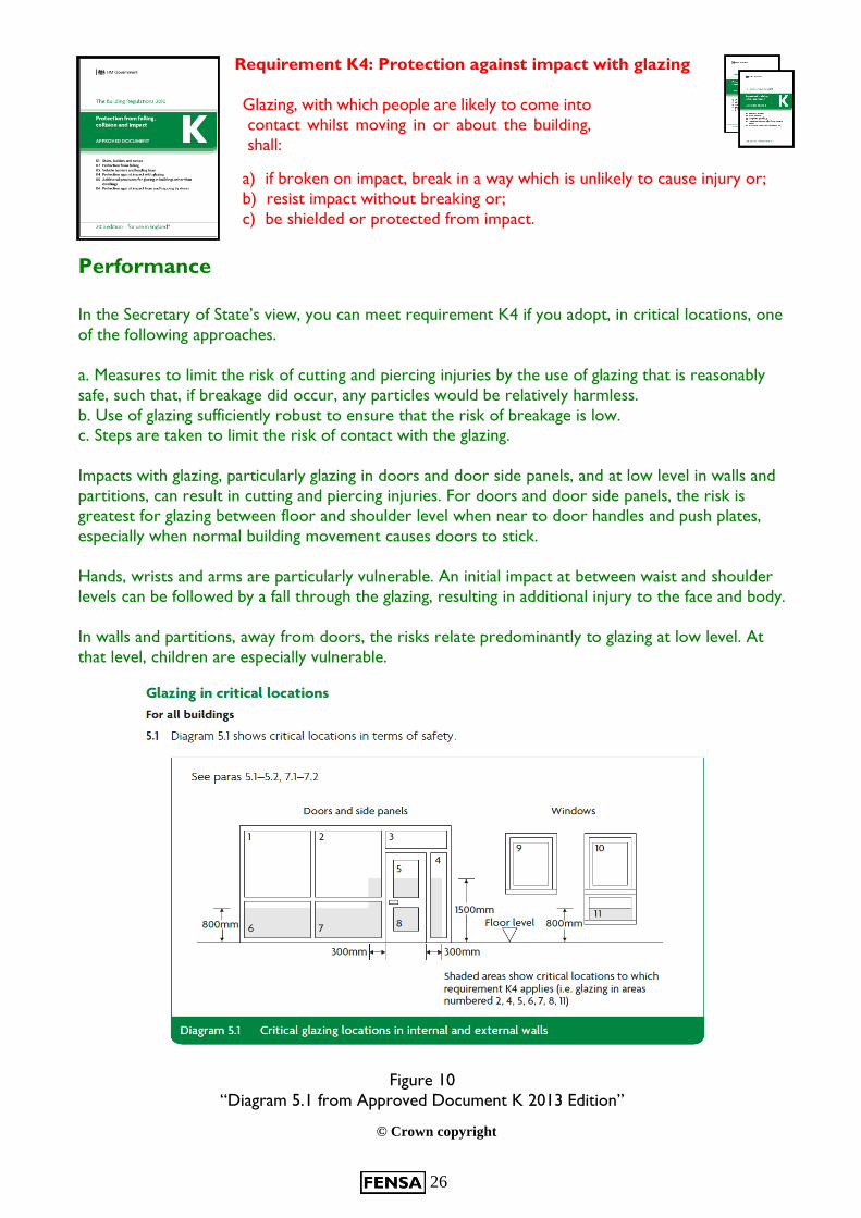
Requirement K4: Protection against impact with glazing
Glazing, with which people are likely to come into
contact whilst moving in or about the building,
shall:
a) if broken on impact, break in a way which is unlikely to cause injury or;
b) resist impact without breaking or;
c) be shielded or protected from impact.
Performance
In the Secretary of State’s view, you can meet requirement K4 if you adopt, in critical locations, one
of the following approaches.
a. Measures to limit the risk of cutting and piercing injuries by the use of glazing that is reasonably
safe, such that, if breakage did occur, any particles would be relatively harmless.
b. Use of glazing sufficiently robust to ensure that the risk of breakage is low. c. Steps are taken to limit the risk of contact with the glazing.
Impacts with glazing, particularly glazing in doors and door side panels, and at low level in walls and
partitions, can result in cutting and piercing injuries. For doors and door side panels, the risk is
greatest for glazing between floor and shoulder level when near to door handles and push plates,
especially when normal building movement causes doors to stick.
Hands, wrists and arms are particularly vulnerable. An initial impact at between waist and shoulder
levels can be followed by a fall through the glazing, resulting in additional injury to the face and body.
In walls and partitions, away from doors, the risks relate predominantly to glazing at low level. At
that level, children are especially vulnerable.
© Crown copyright
Figure 10
“Diagram 5.1 from Approved Document K 2013 Edition”
27
Safe breakage 5.3 Safe breakage is defined in BS EN 12600 section 4 and BS 6206 clause 5.3. In an impact
test, a breakage is safe if it creates one of the following.
a. A small clear opening only, with detached particles no larger than the specified maximum size.
b. Disintegration, with small detached particles.
c. Broken glazing in separate pieces that are not sharp or pointed.
5.4 A glazing material would be suitable for a critical location if it complies with one of the following.
a. It satisfies the requirements of Class 3 of BS EN 12600 or Class C of BS 6206.
b. It is installed in a door or in a door side panel and has a pane width exceeding 900mm and it
satisfies the requirements of Class 2 of BS EN 12600 or Class B of BS 6206.
Note: All glazing in buildings must comply with BS 6262-4 Glazing for Buildings –Part 4 – Code of
Practice for Safety related to Human Impact - Clause 7 Marking for safety glazing.
General
Installed safety glass and safety plastics in critical locations is to be indelibly marked in such a position
so that the marking is visible after installation.
Safety glass
The installed safety glass should be clearly and indelibly marked with the following information:
- the name and trade mark of the manufacturer, merchant or installer
- the identifier of the product standard the safety glass conforms to; e.g. BE EN 12150; BS EN
14179; BS EN 14449;
- the classification according to BS EN 12600
A non-compliance will be recorded during an inspection if the mark is not both
completely visible and clearly legible following installation.
Sliding sash replacement: If any part of the top sash falls below 800 mm from finished floor when opened it must have safety glass installed.
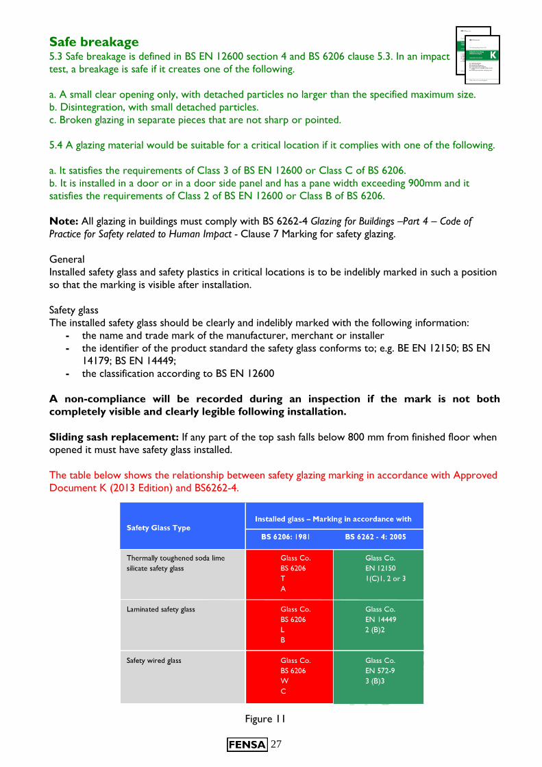
The table below shows the relationship between safety glazing marking in accordance with Approved
Document K (2013 Edition) and BS6262-4.
Figure 11
28
Robustness
5.5 Some glazing materials such as annealed glass gain strength through thickness; others
such as polycarbonates or glass blocks are inherently strong.
The maximum dimensions for annealed glass of different thicknesses for use in large areas
forming fronts to shops, showrooms, offices, factories and public buildings with four edges
supported are shown in Diagram 5.2 (see also paragraph 7.1).
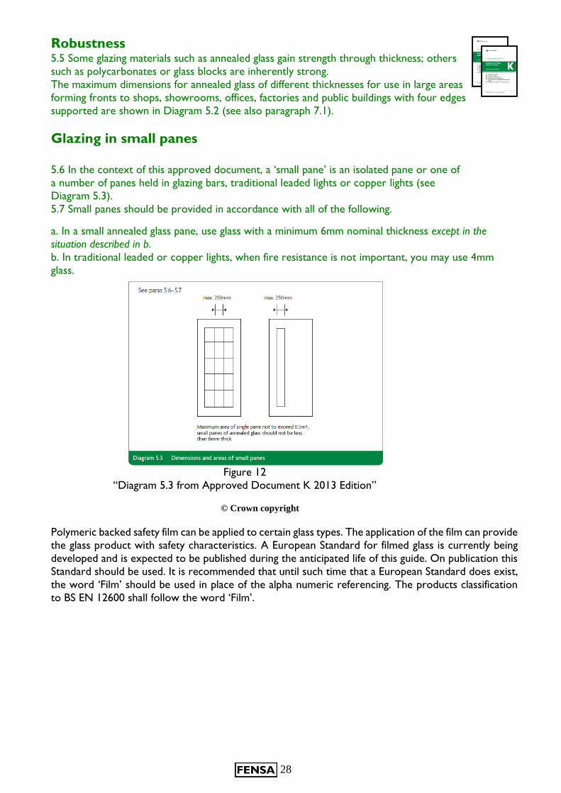
Glazing in small panes
5.6 In the context of this approved document, a ‘small pane’ is an isolated pane or one of
a number of panes held in glazing bars, traditional leaded lights or copper lights (see
Diagram 5.3).
5.7 Small panes should be provided in accordance with all of the following.
a. In a small annealed glass pane, use glass with a minimum 6mm nominal thickness except in the
situation described in b.
b. In traditional leaded or copper lights, when fire resistance is not important, you may use 4mm
glass.
© Crown copyright
Polymeric backed safety film can be applied to certain glass types. The application of the film can provide
the glass product with safety characteristics. A European Standard for filmed glass is currently being
developed and is expected to be published during the anticipated life of this guide. On publication this
Standard should be used. It is recommended that until such time that a European Standard does exist,
the word ‘Film’ should be used in place of the alpha numeric referencing. The products classification
to BS EN 12600 shall follow the word ‘Film’.
Figure 12
“Diagram 5.3 from Approved Document K 2013 Edition”
29
Best Practice Note
The critical locations set out above for the positioning of safety glazing are minimum
requirements. In certain circumstances and in consultation with the customer, it would be
advantageous to supply and install safety glazing material in other situations which the
surveyor considers hazardous following his risk assessment. Consideration should be
given to the type of safety glazing material used. In certain environments the containment
of broken safety glass is crucial.
Although not necessarily a permanent fixture, a bunk bed positioned next to a window could also be
a significant risk
For further information on the use of safety glazing in critical locations, please refer to the GGF
publication ' The Right Glazing in the Right Place'.
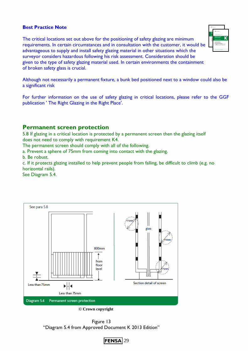
Permanent screen protection 5.8 If glazing in a critical location is protected by a permanent screen then the glazing itself
does not need to comply with requirement K4.
The permanent screen should comply with all of the following.
a. Prevent a sphere of 75mm from coming into contact with the glazing.
b. Be robust.
c. If it protects glazing installed to help prevent people from falling, be difficult to climb (e.g. no
horizontal rails).
See Diagram 5.4.
© Crown copyright
Figure 13
“Diagram 5.4 from Approved Document K 2013 Edition”
30
Approved Document K: (Wales)
Protection from falling,
collision and impact
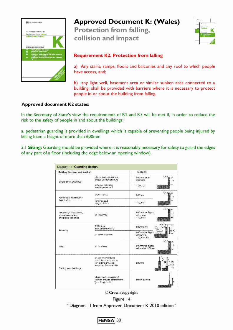
Requirement K2. Protection from falling
a) Any stairs, ramps, floors and balconies and any roof to which people
have access, and;
b) any light well, basement area or similar sunken area connected to a
building, shall be provided with barriers where it is necessary to protect
people in or about the building from falling.
Approved document K2 states:
In the Secretary of State’s view the requirements of K2 and K3 will be met if, in order to reduce the
risk to the safety of people in and about the buildings:
a. pedestrian guarding is provided in dwellings which is capable of preventing people being injured by
falling from a height of more than 600mm
3.1 Siting: Guarding should be provided where it is reasonably necessary for safety to guard the edges
of any part of a floor (including the edge below an opening window).
© Crown copyright
Figure 14
“Diagram 11 from Approved Document K 2010 edition”
31
3.2 Design: Any wall, parapet, balustrade or similar obstruction may serve as guarding.
Guarding should be at least the height shown in Diagram 11 of Approved Document K.
Guarding should be capable of resisting at least the horizontal force given in BS 6399-
1:1996.
For further guidance on design of barriers and infill panels, reference should be made to BS
6180:1995 Code of practice for protective barriers in and around buildings.
The Regulation applies to fixed glazing and opening lights less than 800mm above floor level, where the
floor (or stairs or landing) adjacent to a window is more than 600mm above the outside ground level.
It usually means that low-level opening lights should have restricted openers and all low-level glazing
should be sufficiently robust to resist likely impact.
Compliance can also be achieved by providing alternative guarding e.g. a guard rail or other fixed
barrier, which should cover the zone 800mm above the floor.
For replacement windows and doors the obligation is to make compliance no worse. A replacement
window with a qualifying low-level opening light should be fitted with a restrictor if the outgoing
window was fitted with one. If a new qualifying low-level opening light is introduced into a replacement
window then this should be restricted.
Any fixed glazing less than 800mm above floor level which acts as a barrier to prevent people falling
out should be replaced with glazing which meets the impact resistance requirements of BS 6262-4
taking into account Approved Document K for containment.
Note: This version of Approved Document K now only applies to Wales. Reference should be made
to Approved Document K 2013 Edition for guidance in England.
Best Practice Note
It is recommended that restrictors are always fitted to opening lights less than 800mm above floor
level.
Reference should also be made to Approved Document N Glazing - Safety in relation to impact for
information on safety glazing materials.
Note: Approved Document N (Wales) still refers to BS 6206 however, this standard has been withdrawn for glass. The Safe Breakage element has been replaced by EN 12600 and the Marking of Safety Glass by BS 6262-4: 2005
32
Approved Document L:
Conservation of fuel and power
Requirement L1B
(1) Where a person intends to renovate a thermal element, such work shall be carried out as is necessary to ensure that the whole thermal element
complies with the requirements of paragraph L1(a)(i) of schedule 1.
(2) Where a thermal element is replaced, the new thermal element shall
comply with the requirements of paragraph L1(a)(i) of schedule 1.
Windows
To comply with the 2010 edition of Approved Document L1B, replacement windows should comply
with one of the following:
a) Window Energy Rating minimum (WER) band C
b) Whole window U-Value maximum 1.6 (W/m²∙K)
c) Centre pane U-Value maximum 1.2 (W/m²∙K) (For exceptional circumstances only e.g. historic
buildings or unique windows).
Doors
All replacement doors should have a U-value not exceeding 1.8 (W/m2•K)
Table 1 Section 4 Document L1B
Currently for registration of replacement doors through the competent person’s scheme, only doors and frames with greater than 50% glazing have to be registered.
Note: These new regulations came into force October 1st 2010
33
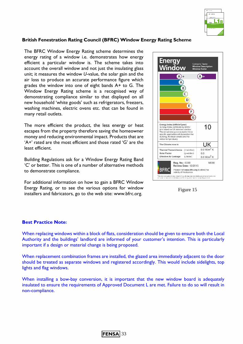
British Fenestration Rating Council (BFRC) Window Energy Rating Scheme
The BFRC Window Energy Rating scheme determines the
energy rating of a window i.e. demonstrates how energy
efficient a particular window is. The scheme takes into
account the overall window and not just the insulating glass
unit; it measures the window U-value, the solar gain and the
air loss to produce an accurate performance figure which
grades the window into one of eight bands A+ to G. The
Window Energy Rating scheme is a recognised way of
demonstrating compliance similar to that displayed on all
new household ‘white goods’ such as refrigerators, freezers,
washing machines, electric ovens etc. that can be found in
many retail outlets.
The more efficient the product, the less energy or heat
escapes from the property therefore saving the homeowner
money and reducing environmental impact. Products that are
‘A+’ rated are the most efficient and those rated ‘G’ are the
least efficient.
Building Regulations ask for a Window Energy Rating Band
‘C’ or better. This is one of a number of alternative methods
to demonstrate compliance.
For additional information on how to gain a BFRC Window
Energy Rating, or to see the various options for window
installers and fabricators, go to the web site: www.bfrc.org.
Best Practice Note:
When replacing windows within a block of flats, consideration should be given to ensure both the Local
Authority and the buildings’ landlord are informed of your customer’s intention. This is particularly
important if a design or material change is being proposed.
When replacement combination frames are installed, the glazed area immediately adjacent to the door
should be treated as separate windows and registered accordingly. This would include sidelights, top
lights and flag windows.
When installing a bow-bay conversion, it is important that the new window board is adequately
insulated to ensure the requirements of Approved Document L are met. Failure to do so will result in
non-compliance.
Figure 15
34
Approved Document M:
Access to and use of buildings
Requirement M1
Reasonable provision shall be made for people to:
a) Gain access to; and
b) Use the building and its facilities.
In the 2013 update sections of Part M were incorporated into Part K (England). The requirement in Wales still uses the 2004 version,
however, the following still applies in both England and Wales:
The requirement of Part M is that you should not make the building less accessible than it was before
the installation. The height of the sill for a door should not be made worse. In practice there is often
a compromise between compliance (not make access worse) and performance (weatherproofing).
When the outgoing door is compliant with new build requirements the replacement shall also be
compliant.
Where the door pre-dates the 2004 legal requirements, the installer should make compliance no
worse, use best efforts to minimise the hazard and comply with the following:
a) Protected doorways, and doors in areas of low weather exposure, should be fitted with a threshold
sill which gives a height of no greater than 35mm.
b) Doors in areas of high exposure, and therefore prone to water ingress, should be fitted with a
threshold height of no greater than 50mm.
c) In some situations, due to design considerations, it may not be possible to install a low threshold
sill of the requirements as stated above. In these situations, a gap of up to 35 mm measured from
the underside of the door leaf to the finished floor level would normally be considered acceptable.
d) The principal entrance to a dwelling should ideally have a clear opening width of 775mm. When
replacing the principal entrance door every practicable effort should be made to retain the
maximum width. The clear opening width is taken from the edge of the frame on the latch side to
the face of the door leaf when open at 90°.
e) All door installations should comply with the requirements of Approved Document C in relation
to resistance to moisture. If the original principle entrance door was fitted after 2004, it should
already be fully compliant with the Building Regulations. If being replaced, only this door needs to
meet the requirement specified within Approved Document M. Although other door replacements
within the property should not have a lesser level of compliance, they are not required to meet
the requirements of Approved Document M.
Further guidance can be provided by the Stationery Office’s publication.
“Accessible thresholds in new housing: Guidance for house builders and designers”.
Best Practice Note
When surveying or specifying a window or door for a dwelling, the surveyor should make note of the
person, or persons occupying or using the dwelling. Special consideration should be given to occupants
with disabilities. It is not possible to provide a universal solution, so the installation should be suited to
the occupants’ requirements. These requirements may include low height door thresholds, increased
width door sets and suitable positioning and type of door furniture.
35
Approved Document N: (Wales)
Glazing - Safety in relation to impact,
opening and cleaning
Requirement N1
Glazing, with which people are likely to come into contact whilst moving in or
about the building, shall:
a) If broken on impact, break in a way which is unlikely to cause injury or;
b) Resist impact without breaking; c) Be shielded or protected from impact.
Safety in use
Where do safety-glazing materials need to be used?
Critical Safety Area Locations
Part of a door, wall or other part of a building likely to be subject to accidental human impact.
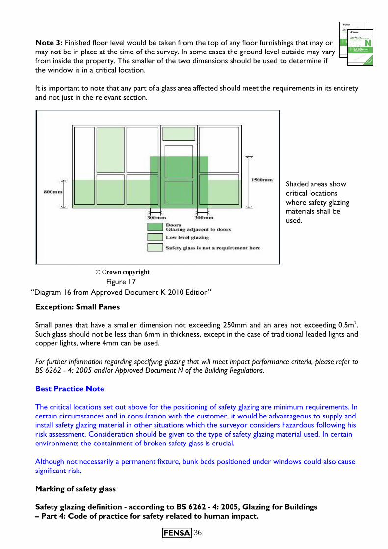
Those areas of internal and external walls see Figure 6, that are considered ‘critical locations’ in terms
of safety are:
Between the finished floor level and 1500mm above that level in doors, and side panels which are
within 300mm of either edge of the door.
Between the finished floor level and 800mm above that level in the case of windows not included in the point above.
Note 1: In areas where the window is situated above a fixture e.g. bath/shower tray or window
seat, the finished floor level is taken from the point on which is stood or sat upon and not the
floor level where the item has been affixed.
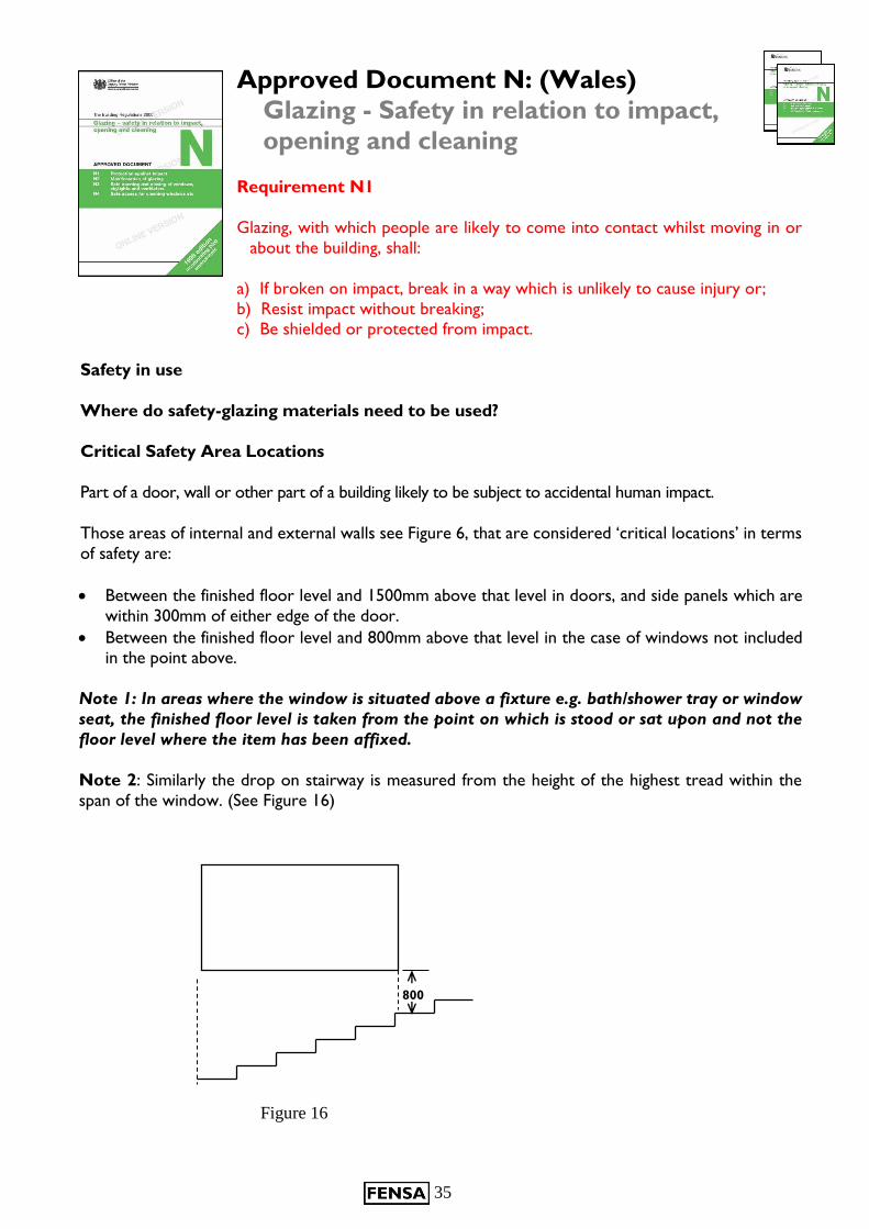
Note 2: Similarly the drop on stairway is measured from the height of the highest tread within the
span of the window. (See Figure 16)
800
Figure 16
36
Note 3: Finished floor level would be taken from the top of any floor furnishings that may or
may not be in place at the time of the survey. In some cases the ground level outside may vary
from inside the property. The smaller of the two dimensions should be used to determine if
the window is in a critical location.
It is important to note that any part of a glass area affected should meet the requirements in its entirety
and not just in the relevant section.
Shaded areas show
critical locations
where safety glazing
materials shall be
used.
© Crown copyright
Exception: Small Panes
Small panes that have a smaller dimension not exceeding 250mm and an area not exceeding 0.5m2.
Such glass should not be less than 6mm in thickness, except in the case of traditional leaded lights and
copper lights, where 4mm can be used.
For further information regarding specifying glazing that will meet impact performance criteria, please refer to
BS 6262 - 4: 2005 and/or Approved Document N of the Building Regulations.
Best Practice Note
The critical locations set out above for the positioning of safety glazing are minimum requirements. In
certain circumstances and in consultation with the customer, it would be advantageous to supply and
install safety glazing material in other situations which the surveyor considers hazardous following his
risk assessment. Consideration should be given to the type of safety glazing material used. In certain
environments the containment of broken safety glass is crucial.
Although not necessarily a permanent fixture, bunk beds positioned under windows could also cause
significant risk.
Marking of safety glass
Safety glazing definition - according to BS 6262 - 4: 2005, Glazing for Buildings
– Part 4: Code of practice for safety related to human impact.
Figure 11 Figure 17
“Diagram 16 from Approved Document K 2010 Edition”
37
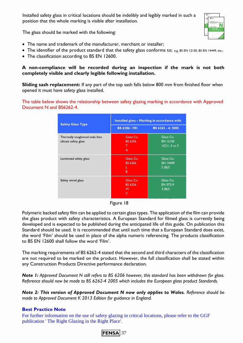
Installed safety glass in critical locations should be indelibly and legibly marked in such a
position that the whole marking is visible after installation.
The glass should be marked with the following:
The name and trademark of the manufacturer, merchant or installer;
The identifier of the product standard that the safety glass conforms to; e.g. BS EN 12150, BS EN 14449, etc.;
The classification according to BS EN 12600.
A non-compliance will be recorded during an inspection if the mark is not both
completely visible and clearly legible following installation.
Sliding sash replacement: If any part of the top sash falls below 800 mm from finished floor when
opened it must have safety glass installed.
The table below shows the relationship between safety glazing marking in accordance with Approved
Document N and BS6262-4.
Installed glass – Marking in accordance with
Safety Glass Type
Polymeric backed safety film can be applied to certain glass types. The application of the film can provide
the glass product with safety characteristics. A European Standard for filmed glass is currently being
developed and is expected to be published during the anticipated life of this guide. On publication this
Standard should be used. It is recommended that until such time that a European Standard does exist,
the word ‘Film’ should be used in place of the alpha numeric referencing. The products classification
to BS EN 12600 shall follow the word ‘Film’.
The marking requirements of BS 6262-4 stated that the second and third characters of the classification
are not required to be marked on the product. However, the full classification shall be stated within
any Construction Products Directive performance declaration.
Note 1: Approved Document N still refers to BS 6206 however, this standard has been withdrawn for glass.
Reference should now be made to BS 6262-4 2005 which includes the European glass product Standards.
Note 2: This version of Approved Document N now only applies to Wales. Reference should be
made to Approved Document K 2013 Edition for guidance in England.
Best Practice Note
For further information on the use of safety glazing in critical locations, please refer to the GGF
publication ' The Right Glazing in the Right Place'.
Figure 18

38
Approved Document 7:
Materials and workmanship
Materials and workmanship 7.
Building work shall be carried out
(a) with adequate and proper materials which
(i) are appropriate for the circumstances in which they are used,
(ii) are adequately mixed or prepared, and
(iii) are applied, used or fixed so as adequately to perform the
functions for which they are designed; and
(b) in a workmanlike manner.
Main changes in the 2013 edition
This approved document supports regulation 7: Materials and workmanship. It takes effect on 1 July
2013 and is for use in England*. The 1999 edition will continue to apply to work started before 1 July
2013, or to work subject to a building notice, full plans application or initial notice submitted before
1 July 2013.
There is no change to Regulation 7. The main amendments in this approved document
are that:
The document has been updated to reflect the full implementation of European Regulation
305/2011/EU-CPR covering construction products, referred to as the Construction Products
Regulation, from 1 July 2013. This Regulation requires that products covered by a harmonised
European product standard or conforming to a European Technical Assessment should normally have
CE marking.
Reference to the environmental impact of building work has been deleted.
Guidance on resistance to moisture and substances in the subsoil has been deleted; this is now
included in Approved Document C.
Examples of materials susceptible to changes in their properties have been deleted. (In the case of
intumescent coatings, durability testing is now an established element of testing of such products.)
A new-style format has been used.
Notification of work Most building work and material changes of use must be notified to a building control body unless one of the following applies.
a. It is work that will be self-certified by a registered competent person or certified by a registered third party.
b. It is work exempted from the need to notify by regulation 12(6A) of, or Schedule 4 to, the Building Regulations.
Responsibility for compliance People who are responsible for building work (e.g. agent, designer, builder or installer) must ensure that the work complies with all applicable requirements of the Building Regulations. The building owner may also be responsible for ensuring that work complies with the Building Regulations. If building work does not comply with the Building Regulations, the building owner may be served with an enforcement notice.

39
Section 1: Materials
1.1 Building work must meet the functional requirements of Schedule 1 to the Building Regulations.
Approved documents refer to materials covered by harmonised European product standards, British
Standards and other technical specifications. However, there is no obligation to adopt any particular
solution contained in an approved document in order to meet functional requirements; the
references are not exclusive and other materials may be suitable in the particular circumstances.
Section 2: Workmanship
Ways of establishing the adequacy of workmanship 2.1 Examples of ways to establish the adequacy of workmanship are described in paragraphs 2.2 to 2.11.
CE marking
2.2 If a material has CE marking, workmanship may be specified in the relevant European Technical Assessment or harmonised product standard.
Standards
2.3 Methods of carrying out different types of work are also given in British Standards or other appropriate technical specifications.
NOTE: The BS 8000 series of standards on workmanship on building sites combines guidance from other BSI codes and standards. The various parts of BS 8000 are listed in appendix B.
Independent certification schemes
2.4 Some independent certification schemes specify how workmanship will deliver a declared level of
performance. The person carrying out the work should show that the workmanship will provide the appropriate level of protection and performance.
2.5 Schemes, including competent person self-certification schemes that register installers of materials
can provide a means of ensuring that work has been carried out by knowledgeable contractors to
appropriate standards.
FENSA is instrumental in the setting up of the Minimum Technical Competence (MTC) scheme in an
effort to raise the standards of workmanship to recognised levels. The issued registration cards will
need to be made available for inspection upon request.
Part of this process is to encourage both surveyors and installation teams to work in accordance
with established Codes of Practice such as:
BS 8213-4: 2007 Windows, doors and rooflights.
Code of practice for the survey and installation of windows and external doorsets, and;
The Good Practice Guide for the Installation of Replacement Windows and Doors.
Poorly installed installations or incorrectly specified materials will be recognised
following an inspection and may incur a non-conformity as a result.

40
ANNEX A
FENSA NOTES FOR GUIDANCE:
Document L1B Compliance
Introduction
The following methods summarise how a window and door replacement company can demonstrate
compliance with Approved Document L1B 2010 for Wales and L1B 2013 for England.
1) Window Energy Ratings
The product must be permanently marked with the appropriate information which enables it to be traced to the Fabricator/Licence Holder.
The expected construction details for the particular licensed product will be available to a
FENSA Inspector at the time of an inspection. The Inspector will verify the construction.
If you are an Installer and buying frames and glass separately and marrying them up to form the complete window you will need to register as a BFRC Authorised Retailer, if the window is
covered by the BFRC WER Scheme. (and doors by the DSER in England)
If you buy completed frames (glass and frame) then when you register the product with FENSA
you will need to register the Licence Number of the product. There is no requirement to be
an Authorised Retailer.
2) Compliance against U-value (windows and doors)
(a) Calculated U-values
A whole window U-value can be calculated for the window or door U value that is being installed
to demonstrate compliance. This can be supplied with the product by the Fabricator or
determined by the FENSA U-value Calculator (or an alternative approved industry calculator) or
calculated by a BFRC Simulator.
The FENSA Calculator is available on line via the FENSA website www.fensa.co.uk. The FENSA
calculator can be used with PVC-U, timber, aluminium and steel framing materials. Results from
the calculator can be stored in the FENSA database under the allocated reference. These details
will be passed to the FENSA Inspectors when you, at the point of registration, indicate that the
installation conforms to a particular calculation held in our database. You can also record in our
database calculations which have been undertaken by other calculators. In these circumstances
you will not need to leave details of the U-value calculation with your customer for our Inspector to access.
(b) CE Marking Declaration of conformity
A CE marking declaration of conformity against BS EN 14351-1:2006+A1:2010
Windows and doors. Product standard, performance characteristics. Windows and external
pedestrian doorsets without resistance to fire and/or smoke leakage characteristics. The
declaration must cover clause 4.12 Thermal Transmittance.
41
3) Default window specification
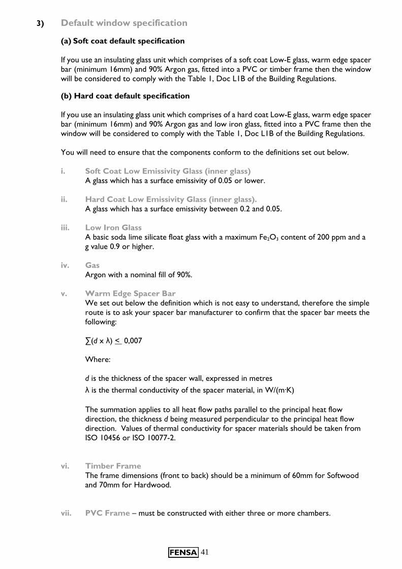
(a) Soft coat default specification
If you use an insulating glass unit which comprises of a soft coat Low-E glass, warm edge spacer
bar (minimum 16mm) and 90% Argon gas, fitted into a PVC or timber frame then the window
will be considered to comply with the Table 1, Doc L1B of the Building Regulations.
(b) Hard coat default specification
If you use an insulating glass unit which comprises of a hard coat Low-E glass, warm edge spacer
bar (minimum 16mm) and 90% Argon gas and low iron glass, fitted into a PVC frame then the
window will be considered to comply with the Table 1, Doc L1B of the Building Regulations.
You will need to ensure that the components conform to the definitions set out below.
i. Soft Coat Low Emissivity Glass (inner glass)
A glass which has a surface emissivity of 0.05 or lower.
ii. Hard Coat Low Emissivity Glass (inner glass).
A glass which has a surface emissivity between 0.2 and 0.05.
iii. Low Iron Glass
A basic soda lime silicate float glass with a maximum Fe2O3 content of 200 ppm and a
g value 0.9 or higher.
iv. Gas
Argon with a nominal fill of 90%.
v. Warm Edge Spacer Bar
We set out below the definition which is not easy to understand, therefore the simple
route is to ask your spacer bar manufacturer to confirm that the spacer bar meets the
following:
∑(d x λ) < 0,007
Where:
d is the thickness of the spacer wall, expressed in metres
λ is the thermal conductivity of the spacer material, in W/(m·K)
The summation applies to all heat flow paths parallel to the principal heat flow
direction, the thickness d being measured perpendicular to the principal heat flow
direction. Values of thermal conductivity for spacer materials should be taken from
ISO 10456 or ISO 10077-2.
vi. Timber Frame
The frame dimensions (front to back) should be a minimum of 60mm for Softwood
and 70mm for Hardwood.
vii. PVC Frame – must be constructed with either three or more chambers.
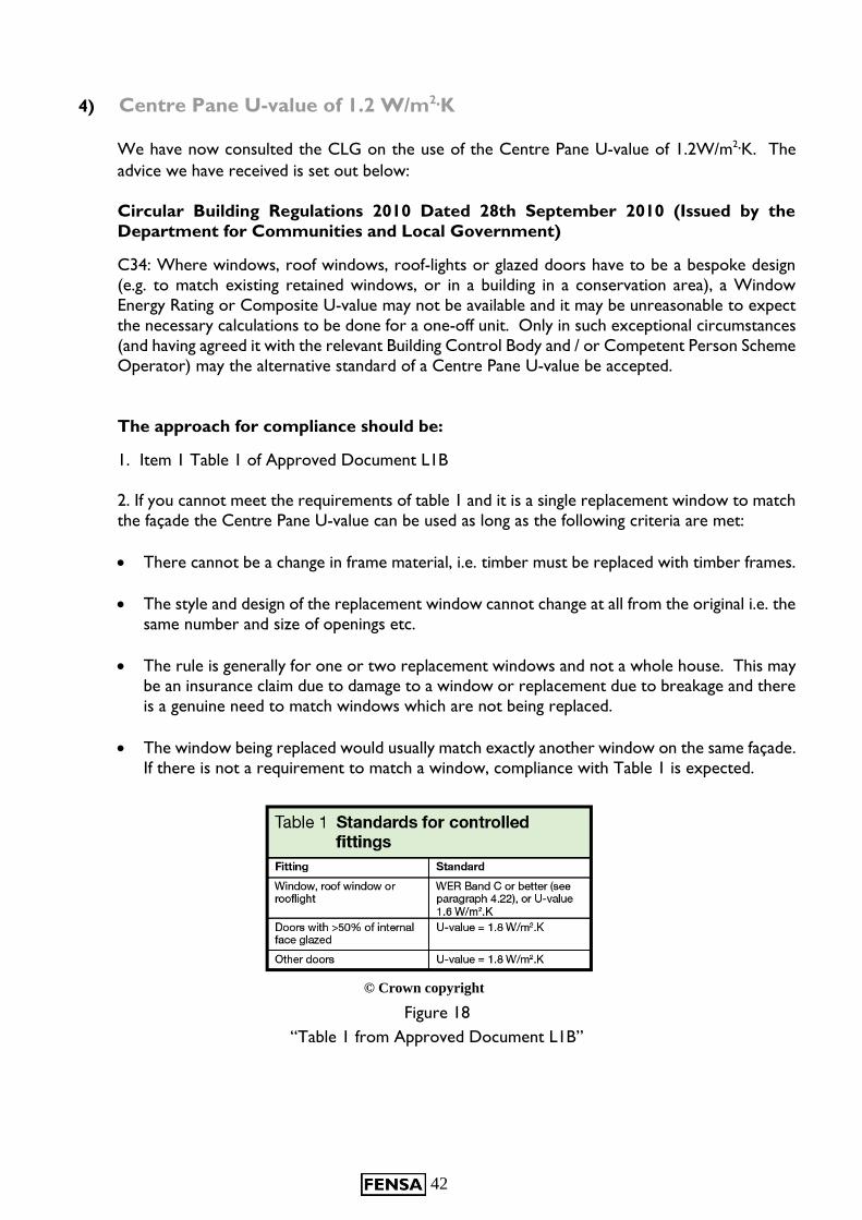
42
4) Centre Pane U-value of 1.2 W/m2·K
We have now consulted the CLG on the use of the Centre Pane U-value of 1.2W/m2·K. The
advice we have received is set out below:
Circular Building Regulations 2010 Dated 28th September 2010 (Issued by the
Department for Communities and Local Government)
C34: Where windows, roof windows, roof-lights or glazed doors have to be a bespoke design
(e.g. to match existing retained windows, or in a building in a conservation area), a Window
Energy Rating or Composite U-value may not be available and it may be unreasonable to expect
the necessary calculations to be done for a one-off unit. Only in such exceptional circumstances
(and having agreed it with the relevant Building Control Body and / or Competent Person Scheme
Operator) may the alternative standard of a Centre Pane U-value be accepted.
The approach for compliance should be:
1. Item 1 Table 1 of Approved Document L1B
2. If you cannot meet the requirements of table 1 and it is a single replacement window to match
the façade the Centre Pane U-value can be used as long as the following criteria are met:
There cannot be a change in frame material, i.e. timber must be replaced with timber frames.
The style and design of the replacement window cannot change at all from the original i.e. the
same number and size of openings etc.
The rule is generally for one or two replacement windows and not a whole house. This may
be an insurance claim due to damage to a window or replacement due to breakage and there
is a genuine need to match windows which are not being replaced.
The window being replaced would usually match exactly another window on the same façade.
If there is not a requirement to match a window, compliance with Table 1 is expected.
© Crown copyright
Figure 18
“Table 1 from Approved Document L1B”
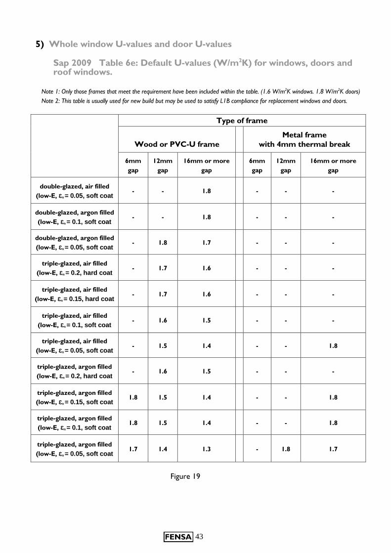
43
5) Whole window U-values and door U-values
Sap 2009 Table 6e: Default U-values (W/m2K) for windows, doors and roof windows.
Note 1: Only those frames that meet the requirement have been included within the table. (1.6 W/m2K windows. 1.8 W/m2K doors)
Note 2: This table is usually used for new build but may be used to satisfy L1B compliance for replacement windows and doors.
Type of frame
Wood or PVC-U frame
Metal frame
with 4mm thermal break
6mm
gap
12mm
gap
16mm or more
gap
6mm
gap
12mm
gap
16mm or more
gap
double-glazed, air filled
(low-E, Ɛn = 0.05, soft coat - - 1.8 - - -
double-glazed, argon filled
(low-E, Ɛn = 0.1, soft coat - - 1.8 - - -
double-glazed, argon filled
(low-E, Ɛn = 0.05, soft coat - 1.8 1.7 - - -
triple-glazed, air filled
(low-E, Ɛn = 0.2, hard coat - 1.7 1.6 - - -
triple-glazed, air filled
(low-E, Ɛn = 0.15, hard coat - 1.7 1.6 - - -
triple-glazed, air filled
(low-E, Ɛn = 0.1, soft coat - 1.6 1.5 - - -
triple-glazed, air filled
(low-E, Ɛn = 0.05, soft coat - 1.5 1.4 - - 1.8
triple-glazed, argon filled
(low-E, Ɛn = 0.2, hard coat - 1.6 1.5 - - -
triple-glazed, argon filled
(low-E, Ɛn = 0.15, soft coat 1.8 1.5 1.4 - - 1.8
triple-glazed, argon filled
(low-E, Ɛn = 0.1, soft coat 1.8 1.5 1.4 - - 1.8
triple-glazed, argon filled
(low-E, Ɛn = 0.05, soft coat 1.7 1.4 1.3 - 1.8 1.7
Figure 19

44
Further information
Additional information for the survey and installation of windows and doors can be found within
the publications:
BS 8213-1: 2004 Windows, doors and rooflights – Part 1: Design for safety in use and during cleaning of windows, including door-height windows and roof windows – Code of practice.
BS 8213-4: 2007 Windows, doors and rooflights – Part 4: Code of practice for the survey
and installation of windows and external doorsets.
These can be purchased from British Standards Institution.
Additional information to aid a window and door installer to comply with the Building
Regulations for both England and Wales can be obtained from the FENSA Building Regulations
Technical Helpline:
Tel: 0870 850 9957
Any other FENSA enquiries should be directed to the general contact details:
Tel: 020 7645 3700
Fax: 020 7407 8307
www.fensa.org.uk
www.fensaonline.com

45
Notes
46
10
Notes
FENSA
54 Ayres Street
London SE1 1EU
Telephone 020 7645 3700
Facsimile 020 7407 8307w.fensa.org.