walk-in monitoring system 200 - american panel · thank you, and congratulations on your purchase...
TRANSCRIPT

REV. 1/18/16
Cooler is Better!TM
Walk-in Monitoring System 200
Used in UL Listed Door Panel Assemblies
American Panel Corporation 5800 S.E. 78th Street, Ocala, Florida 34472-3412
Phone: (352) 245-7055 Fax: (352) 245-0726 E-mail: [email protected]

Thank you, and congratulations on your purchase of an American Panel Walk-in Monitoring System 200. We take great pride in engineering and manufacturing each of our products. With the goal of providing the highest accuracy and quality possible, our state-of-the-art manufacturing and quality control facility enables us to continually explore new technologies so that we can provide you with the finest equipment in the industry. Because of our commitment to your satisfaction, we have developed this Owner’s Manual to guide you through the complete installation process, and to help you maintain your equipment properly. Familiarization and compliance with this manual will ensure you years of trouble-free operation. On occasion situations can arise and will require the help of the factory, whether it be technical information, service or replacement of parts. We have a highly trained Customer Service and Parts Department available to help when these situations arise. We also offer a national network of service agencies that may be contacted for warranty and out-of-warranty service. When contacting the factory, please refer to the equipment serial number which can be located on the identification plate positioned on the interior of the door frame. Thank you once again for your purchase of American Panel equipment.
“Our reputation rests on the steadfast pursuit of your satisfaction”.
American Panel Corporation 5800 S.E. 78th Street, Ocala, Florida 34472-3412
Phone: (352) 245-7055 Fax: (352) 245-0726 E-mail: [email protected]
E78551

INTRODUCTION
3
Index 1. INTRODUCTION AND FEATURES ................................................................................................................................................. 4
1.1. TEMPERATURE MONITORING AND ALARMS ............................................................................................................................................... 4 1.2. DOOR FRAME HEATER TEMPERATURE CONTROL AND MONITORING .............................................................................................................. 4 1.3. HACCP COMPLIANT DATA LOGGER AND THE PC COMMUNICATION PROTOCOL AND SOFTWARE ........................................................................ 5 1.4. ELECTRONICALLY CONTROLLED LIGHT SWITCH AND AUTOMATIC LIGHT OFF .................................................................................................... 5
2. CONTROLLER ............................................................................................................................................................................. 6
3. PARAMETER PROGRAMMING .................................................................................................................................................... 7
4. CHANGE THE ACCESS CODE ...................................................................................................................................................... 12
5. TECHNICIAN MENU (CELSIUS/FAHRENHEIT UNIT SELECTION, TEMPERATURE PROBE OFFSET, PC CONNECTION SETTINGS, HACCP DATA RECORDING SETTINGS) ........................................................................................................................................... 14
6. RESTORE THE DEFAULT SETTINGS ............................................................................................................................................ 17
7. OPERATING WIMS 200 ............................................................................................................................................................. 18
7.1. TURN ON THE CONTROLLER ................................................................................................................................................................. 18 7.2. READ THE WALK‐IN AIR TEMPERATURE AND THE CURRENT TIME ............................................................................................................... 18 7.3. DISPLAY THE CURRENT DATE AND TIME ................................................................................................................................................. 18 7.4. DISPLAY THE DOOR FRAME HEATER TEMPERATURE .................................................................................................................................. 18 7.5. OPERATE THE LIGHT SWITCH ................................................................................................................................................................ 19 7.6. HIGH ALARM .................................................................................................................................................................................... 19 7.7. LOW ALARM ..................................................................................................................................................................................... 19 7.8. PANIC BUTTON (OPTIONAL) ................................................................................................................................................................. 19 7.9. DOOR SWITCH ................................................................................................................................................................................... 19
8. HACCP DATA DOWNLOAD VIA SD/MMC .................................................................................................................................. 20
8.1. CLEAR THE EVENTS MEMORY ............................................................................................................................................................... 22
9. ERROR MESSAGES ................................................................................................................................................................... 23
9.1. TEMPERATURE PROBE FAILURE MESSAGES ............................................................................................................................................. 23 9.2. POWER FAILURE MESSAGE .................................................................................................................................................................. 24 9.3. SD CARD OPERATION ERROR MESSAGE ................................................................................................................................................. 24
10. BATTERIES ............................................................................................................................................................................. 25
10.1. CONNECT THE BATTERY PACK ............................................................................................................................................................ 25 10.2. REPLACE THE BATTERIES ................................................................................................................................................................... 25
11. PC CONNECTION KIT AND SOFTWARE (OPTIONAL) ................................................................................................................. 26
11.1. PACKAGE CONTENT .......................................................................................................................................................................... 26 11.2. CONNECT WIMS 200 TO YOUR PC .................................................................................................................................................... 26 11.3. PC CONNECTION FOR TWO OR MORE CONTROLLERS ............................................................................................................................. 27 11.4. COMMUNICATION SOFTWARE CPX‐200 .............................................................................................................................................. 28
11.4.1. Special Operation Menu ...................................................................................................................................................... 28 11.4.2. Panel Operation Menu ........................................................................................................................................................ 29
11.5. PC CONNECTION TROUBLESHOOTING .................................................................................................................................................. 30 11.5.1. Blank Display ....................................................................................................................................................................... 30
12. FIELD WIRING ........................................................................................................................................................................ 31
13. ELECTRICAL DIAGRAM ........................................................................................................................................................... 32
13.1. WIRING DIAGRAM ........................................................................................................................................................................... 32 13.2. PC CONNECTION WIRING DIAGRAM .................................................................................................................................................... 36
14. APPENDIX 1 AIR TEMPERATURE PROBE OFFSET ..................................................................................................................... 37

INTRODUCTION
4
1. Introduction and Features
WALK-IN MONITORING SYSTEM 200 (WIMS 200) was designed by American Panel Corporation to address multiple issues regarding walk-in units and to incorporate the functionalities of various walk-in door devices in a single, flexible, reliable, and user friendly controller. WIMS 200 features:
Walk-in Temperature Monitoring Walk-in Temperature Alarms External Alarm Output With Direct 115VAC, Up To 150W Door Frame Heater Temperature Controlling Door Frame Heater Temperature Monitoring Real Time Clock And Date With Backup Battery And Automatic Recharge Function Communication Protocol With Software For PC Connection (Optional) SD/MMC Card With USB Adapter HACCP Compliant Data Logger Electronically Controlled Light Switch With Light On/Off Indicator Automatic Light Off External Switch Connection For CAL-OSHA Back-To-Back Light Control (Optional) Multi-Way (3 Or 4 Ways) Light Control (Optional) Panic Button (Optional) Door Switch Celsius Or Fahrenheit Temperature Selection
1.1. Temperature Monitoring and Alarms
To efficiently monitor the walk-in air temperature, WIMS 200 is equipped with a highly accurate temperature probe mounted inside the walk-in. The temperature readings are displayed on an ultra bright dot matrix LED display.
The controller alarm system is comprised of a high and low temperature alarm with built in trigger delay to allow small temperature fluctuations (occurring in daily walk-in operations such as door openings, door closings, and evaporator defrost cycles) without triggering the alarms. The alarm’s set points and delay times are fully programmable to the user’s needs.
In case the air temperature inside the walk-in is reaching an alarm condition, WIMS 200 uses visual and audible alert methods. In addition to the integrated buzzer and alarm display message, the controller has a 120V/60Hz/150W output for additional external alarm devices (optional).
1.2. Door Frame Heater Temperature Control and Monitoring
Door frame heater control and monitoring is done by two different methods that work in conjunction to save energy and to maintain the door frame heater temperature within a preset range.
A temperature probe is mounted on the door frame heater wire to accurately monitor its temperature. Viewing the door frame heater temperature is as easy as pressing a button.

INTRODUCTION
5
1.3. HACCP Compliant Data Logger and the PC Communication Protocol and Software
American Panel Corporation understands the benefits and the importance of a complete HACCP system. That is why we designed WIMS 200 to incorporate a complete Critical Temperature Control Points monitoring system. WIMS 200 records the temperature inside the walk-in at preset time intervals. Also, it records the occurrence of critical events such as air alarms, panic alarms, and power failures together with the date and time of the occurrence. When needed, this data can be viewed and printed from a computer via the communication protocol or the provided SD card and USB adapter. The HACCP system is backed-up by a self-rechargeable battery system and a real time clock.
In the event of a power failure, WIMS 200 will display a power failure message that alternates with the common readings (air temperature and time). It will continue to record the events until the battery is depleted, approximately four more hours.
The PC connection interface was designed to allow the user to monitor and control the WIMS 200 from the convenience of the office computer. The software’s interface emulates the control panel.
1.4. Electronically Controlled Light Switch and Automatic Light Off
The flexibility of WIMS 200 allows the user to operate the light from multiple locations such as multiple doors. The integrated light button is equipped with two LED lights to display the ON/OFF status of the light and also to indicate the button location in the dark.
The Automatic Light Off feature of WIMS 200 enables the user to save energy. The amount of time the light will stay on can be set from 1 minute to 60 minutes, or it can be set for manual shut off.
Back-to-back and multi-way light controls are provided as optional features.

CONTROLLER
6
2. Controller

PROGRAMMING
7
3. Parameter Programming
All American Panel Corporation walk-in monitoring systems are programmed at the factory. The settings in this manual are considered default for WIMS 200 and were established to suit generic walk-in operating environments. However, the customer may change any of these settings as required.
Note: During the programming steps, any delay longer than one minute before pushing the next button will cause the controller to revert to the “OFF” state. To avoid this, the following instructions should be carefully reviewed and the desired settings should be determined before proceeding. If the controller goes to the “OFF” state, the programming mode will have to be restarted.
Note: During programming, pressing and holding the UP or DOWN button will increase the programming speed.
The instructions below contain screens with the exact messages displayed by the controller during the programming procedure. Follow the notes located to the left of these screens.
Before entering the programming mode, the controller has to be in the “OFF” state.
If it is not, press and hold for five seconds. The display will show:
To enter the programming mode, press and hold for five seconds.
The display will show:
Enter The Access Code
To enter the default access code, press the following buttons in order: .
When finished, press .
Note: If the code entered is not correct, the controller will display the error message and switch back to the previous screen.
Note: The access code is a safety feature that limits the access to the programming mode and therefore will prevent unauthorized personnel from tampering with the settings.
The display will show:
After entering the code successfully, the controller will ask you if you want to
change the code. To leave it unchanged, press .

PROGRAMMING
8
The display will show: Battery Charge
Press or to set the flashing value to “Y” (Yes) to enable the battery charging feature.
Press when done. Next, WIMS 200 will check the battery and display the message on the right for a few seconds. Once the controller detects the batteries, it will prompt you for the time settings.
Note: If the battery charge function is disabled, the “Batt.” message will not be displayed.
The display will show: Real Time Clock Settings
Press or to set the flashing value to “Y” (Yes) if you wish to enable the real time clock. If real time clock is enabled, the time will be displayed during normal operation.
Press when done.
The display will show:
Press or to change the flashing value to current year.
Press when done.
The display will show:
Press or to change the flashing value to current month.
Press when done.

PROGRAMMING
9
The display will show:
Press or to change the flashing value to current day.
Press when done.
The display will show:
Press or to change the flashing value to current time in one minute increments.
Press and hold or to change to current time in thirty minute increments.
Press when done.
(12:00 AM)
(12:00 PM)
The display will show: Door Frame Heater Settings
This function will turn the door frame heater on (“Y”) or off (“N”).
By default, the door frame heater is set to on. If you wish to turn the door frame heater off, change the
flashing value from “Y” to “N”(off) by pressing or .
Press when done.
Note: If you set the flashing value to “N”, door frame heater off, the controller will skip to alarm settings. In case the flashing value is set to “Y”, door frame heater on, the controller will guide you thru door frame heater settings.
The display will show:
This function will display the walk-in temperature which will determine when the door frame heater will start. Set the air temperature inside the walk-in at which the door frame heater will
start. To do so press to increase or to decrease the flashing value representing the air temperature.
Press when done.

PROGRAMMING
10
The display will show: This function will set the door frame heater temperature.
Press or to change the door frame heater temperature (the flashing value).
Once the door frame heater temperature reaches this setting, it will stay close to the set point, according to the factory set differential.
Note: Set the door frame heater temperature between 750F and 1200F.
Press when done.
(Default value for coolers)
(Default value for freezers)
The display will show:
Press or to set the percentage (flashing value) of the 4 minute cycle which the door frame heater will stay on. The remaining time left of the 4 minute cycle the door frame heater will be off. This cycle will repeat for as long as the controller is on.
See the examples below.
(Default value for coolers)
(Default value for freezers)
Ex1: If the flashing value is set 75%, the door frame heater will run for 3 minutes and it will be off for 1 minute. This cycle will repeat for as long as the controller is on. Ex2: If the flashing value is set to 100%, the door frame heater will run continuously. Ex3: If the flashing value is set to 0%, the door frame heater will not run at all. Ex4: If the flashing value is set to 50%, the door frame heater will run for 2 minutes and it will be off for 2 minutes. The cycle will repeat for as long as the controller will be on.
Note: Do not set door frame heater percent to 0% unless you want to turn the door frame heater off.
Press when done.
The display will show: Alarm Settings
Set the high air alarm. To do so, press or to change the flashing value representing degrees Fahrenheit. If the air temperature goes above this set point, the alarm will go off.
Press when done.
(Default value for coolers)
(Default value for freezers)

PROGRAMMING
11
The display will show:
Set the low air alarm. To do so, press or to change the flashing value representing degrees Fahrenheit. If the air temperature goes below this set point, the alarm will go off. You can set low air alarm anywhere between -300F and 500F.
Press when done.
(Default value for coolers)
(Default value for freezers)
The display will show:
Set the alarm time delay. To do so, press or to change the flashing value representing minutes.
If the air temperature goes out of the preset limits the alarm will go off only after the time set here elapses. The alarm time delay can be set anywhere between 0
(no delay) and 60 minutes. Press when done.
The display will show: Light Off Delay
Next, the controller will prompt you to set the automatic light off delay.
The automatic light off delay is the elapsed time between the moment the user turns the light on and the moment the controller will automatically turn it off.
Set the automatic light off delay by pressing or to change the flashing value representing minutes. The automatic light off delay can be set between 1 and 60 minutes. In case you do not want an automatic light off delay, set this function to “∞”.
Press when done.
The display will show:
PROGRAMMING
12
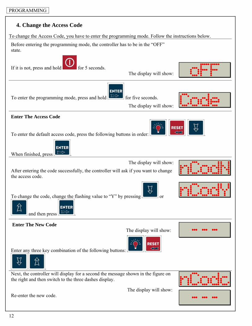
4. Change the Access Code
To change the Access Code, you have to enter the programming mode. Follow the instructions below.
Before entering the programming mode, the controller has to be in the “OFF” state.
If it is not, press and hold for 5 seconds. The display will show:
To enter the programming mode, press and hold for five seconds.
The display will show:
Enter The Access Code
To enter the default access code, press the following buttons in order: .
When finished, press .
The display will show:
After entering the code successfully, the controller will ask if you want to change the access code.
To change the code, change the flashing value to “Y” by pressing or
and then press .
Enter The New Code The display will show:
Enter any three key combination of the following buttons:
. Next, the controller will display for a second the message shown in the figure on the right and then switch to the three dashes display.
The display will show: Re-enter the new code.

PROGRAMMING
13
After successfully re-entering the new code, the controller will briefly display the message shown in the figure on the right.
The display will show:
If you wish to skip parameter programming press until you get to the OFF message.
To change the controller parameters, see the “Parameter Programming” section of this manual.
Make a note of the new code.

PROGRAMMING
14
5. Technician Menu (Celsius/Fahrenheit Unit Selection, Temperature Probe Offset, PC Connection Settings, HACCP Data Recording Settings)
Note: The technician menu includes settings that if changed could interfere with the functionality of the controller. Enter the technician menu only if it is absolutely necessary.
Before entering the technician menu, the controller has to be in the “OFF” state.
If it is not, press and hold for 5 seconds. The display will show:
Press and hold for 10 seconds.
The display will show:
Enter The Access Code
To enter the default access code, press the following buttons in order: .
When finished, press .
The display will show:
Select The Displayed Unit Of Temperature (Celsius/Fahrenheit)
To change the displayed unit of temperature (the flashing value) from Fahrenheit
to Celsius, press or .
When finished, press .
The display will show:
This setting is for factory technician only. Press to skip.
The display will show:
This setting is for factory technician only. Press to skip.

PROGRAMMING
15
The display will show:
Adjust the Probe Temperature Offset
Press or to match the flashing value with the temperature offset (TOFFSET) calculated in Appendix 1 of this manual.
When finished, press .
The display will show:
This setting is for factory technician only. Press to skip.
The display will show:
This setting is for factory technician only. Press to skip.
The display will show: Configure The PC Connection This setting enables or disables the PC connection. If you purchased the PC connection kit make sure you enable the PC connection.
Note: If you disable the PC connection (flashing value set to “N”), the controller will skip the PC connection settings.
To enable the PC connection, set the flashing value to “Y” by pressing or .
When finished, press .
The display will show:
Set the Controller’s Id Number The Id number identifies that particular controller when there is more then one controller connected to the same PC. Set different Id numbers for each WIMS 200 controller connected to the same PC. To do so, change the flashing
value by pressing or .
When finished, press .

PROGRAMMING
16
The controller will switch to the baud rate setting and the display will show the message on the right for a few seconds.
The display will show:
38400 is a common baud rate for the most computers. Press to leave this setting unchanged.
The display will show:
This setting is for factory technician only. Press to skip.
The display will show:
This setting is for factory technician only. Press to skip.
The display will show:
This setting is for factory technician only. Press to skip.
The display will show:
This setting is for factory technician only. Press to skip.
The display will show: HACCP Data Recording Settings
The flashing value represents the recording time interval in minutes for the HACCP data. By default the recording time interval is set to 15 minute. This means that every 15 minutes the WIMS 200 will write the HACCP data in its own memory.
Press or to increase or decrease the recording time interval.
When finished, press .
The display will show:

PROGRAMMING
17
6. Restore The Default Settings
Note: After restoring the default settings, you may have to reprogram the controller. Pay special attention to the door frame heater settings.
To restore the default settings, press and hold for ten seconds.
The display will show:
Press .
OPERATING
18
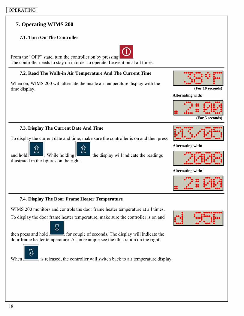
7. Operating WIMS 200
7.1. Turn On The Controller
From the “OFF” state, turn the controller on by pressing . The controller needs to stay on in order to operate. Leave it on at all times.
7.2. Read The Walk-in Air Temperature And The Current Time
When on, WIMS 200 will alternate the inside air temperature display with the time display. (For 10 seconds)
Alternating with:
(For 5 seconds)
7.3. Display The Current Date And Time
To display the current date and time, make sure the controller is on and then press
and hold . While holding the display will indicate the readings illustrated in the figures on the right.
Alternating with:
Alternating with:
7.4. Display The Door Frame Heater Temperature
WIMS 200 monitors and controls the door frame heater temperature at all times.
To display the door frame heater temperature, make sure the controller is on and
then press and hold for couple of seconds. The display will indicate the door frame heater temperature. As an example see the illustration on the right.
When is released, the controller will switch back to air temperature display.

OPERATING
19
7.5. Operate The Light Switch
To turn the light on, press . The green LED, next to the light button, will illuminate indicating ON
status of the light. To turn the light off, press one more time. The green LED will go off and the red LED will illuminate indicating OFF status of the light. If the automatic light off feature is enabled, the light will turn off automatically after the preset time expires.
Note: Regardless of the automatic light off setting, the light can be switched on and off from the light button at any time.
If a back-to-back or multi-way light control option was purchased, the light can also be switched on and off from the provided push buttons.
7.6. High Alarm
If the air inside the walk-in goes above the preset high limit, the alarm will go off. The buzzer will go off and the display will flash the following message:
7.7. Low Alarm
If the air inside the walk-in goes below the preset low limit, the alarm will go off. Just as in high alarm event, the buzzer will go off and the display will flash the message illustrated in the figure on the right:
In both cases, Low Alarm and High Alarm, the integrated alarm buzzer and the optional external alarm can be
turned off by pressing . However, the visual alarm message will stay on the display until the air temperature enters the preset range.
7.8. Panic Button (Optional)
The panic button is an optional feature. A permanently illuminated red button will be installed inside the walk-in. When this button is pressed, the light will turn on, the integrated buzzer and the external alarm will go off, and the display will flash the message indicated in the figure on the right.
Press button to cancel the panic alarm.
7.9. Door Switch
The display will flash:
When the door is open the display will flash the message indicated in the figure on the right.

OPERATING
20
8. HACCP Data Download Via SD/MMC
Note: Do not remove the SD card until the controller is in “OFF” state.
WIMS 200 incorporates a complete HACCP monitoring system. The integrated memory allows the controller to store data over a few days of normal operation. We believe it is a good practice to download HACCP data daily.
To download HACCP data onto your computer via the SD/MMC card, follow the instructions below.
Make sure the controller is in “OFF” state. If it is not, press and hold until the display indicates “OFF” (approximately five seconds). Once the controller is in “OFF” state insert the provided SD/MMC card into the SD slot at the controller, as shown in the figure on the right.
When the SD card has been completely inserted into its slot, the display will show:
Press to save the data onto the SD card.
While data is being written on the SD card, the display will indicate the message:
After the controller writes all the information on the SD card, it will verify the integrity of the data. The display will show:
Once the process is finished the controller will return into “OFF” state.
The display will show:
To remove the SD card from the controller press and release the card.
Place the card in the provided USB adapter and insert the adapter into a USB port at your computer.
On the SD card the data is saved as a text file of type EVT00001.txt in folder CPX200 and subfolder of type WWYYXXXX (W – week, Y – year, X – index number). The subfolder name represents the identity code of the controller.
Copy the file onto your computer. Even though the file can be opened with any word editing program, the data layout is optimized for Microsoft Excel. See figure below for an example.

OPERATING
21
Column A represents the index number of the event Column B indicates the occurrence date of the event Column C indicates the occurrence time of the event Column D indicates the event type (see below for a list of the possible event types). Columns E & F indicate the temperature of the air inside the walk-in. Columns G & H indicate the door frame heater temperature.
Event Types:
POWER ON – this event occurs when the board is powered SLEEP MODE – sleep mode is a one time event that enables the controller to save the batteries
while in transit to the customer, PROBE TEMP – reads the air and door frame heater temperature at preset time intervals (15
min. default) POWER FAIL – occurs in the event of an electrical power failure to the controller PROBE TEMP PFAIL – reads the air and door frame heater temperature during the power failure event BATTERY FAIL – if the electrical power failure lasts for an extended period of time, the battery
will eventually fail BATTERY CUT – occurs immediately after the battery fail event, the battery is disconnected from
the system SYSTEM ON – occurs when the system is turned “ON” from the “OFF” mode SYSTEM OFF – occurs when the system enters the “OFF” mode AIR HIGH ALARM – occurs when the air inside the walk-in goes above the preset high limit AIR LOW ALARM – occurs when the air inside the walk-in goes below the preset low limit PANIC ALARM – occurs when the panic button inside the walk-in is pressed RESET PANIC – occurs when the panic alarm is reset DOOR OPEN – the door switch enables WIMS 200 to record when the walk-in door is opened DOOR CLOSED – the door switch enables WIMS 200 to record when the walk-in door is closed AIR PROBE N/G – occurs when the air temperature probe fails HEATER PROBE N/G – occurs when the temperature probe for the door frame heater fails BREAK – occurs when the temperature probe fails because the probe wire does not have
continuity SHORT – occurs when the temperature probe fails because there is a short-circuit in the
probe wire

OPERATING
22
8.1. Clear the Events Memory
WIMS 200 memory can store 817 events. When the memory is full, it will take more time to download the data onto the SD card. Clearing the events memory on a regular basis will ensure faster data downloading onto the SD card. Note: Clear the events memory only after the existing data was downloaded, checked and saved!
Before attempting to clear the events memory, the controller has to be in the “OFF” state.
If it is not, press and hold for 5 seconds. The display will show:
Press and at the same time and hold for 10 seconds.
The display will blink:
To clear the events memory press .
The display will show:
After 10 second, the display will revert to “OFF” state.

OPERATING
23
9. Error Messages
Problems beyond the routine maintenance would most likely involve the refrigeration system or the control system. Please contact the factory for assistance if this should occur. Note that the warranty would be voided if these components are serviced by other than trained technicians approved by the manufacturer.
There are few error messages that could occur on WIMS 200 display:
9.1. Temperature Probe Failure Messages
If any of the above error messages occur, call a technician to check the integrity of the probes. Here is a chart with acceptable electrical resistance (Ohm) at various temperatures for the temperature probes.
oC oF kOhm0 32 27.28 25 77 10.00
Air Probe Not Good
The display will show:
In case the air probe is malfunctioning the display will show the message on the right followed by an indication of the problem.
Alternating with:
(short circuit)
or
(broken wire)
Door Frame Heater Probe Not Good
The display will show:
In case the door frame heater probe is malfunctioning the display will show the message on the right followed by an indication of the problem.
Alternating with:
(short circuit)
or
(broken wire)

OPERATING
24
9.2. Power Failure Message
The display will show:
In the event of a power failure at the controller the display will flash the power fail message and then it will alternate with the temperature reading and the time reading.
(For 5 seconds)
Alternating with:
(For 10 seconds)
Alternating with:
(For 5 seconds)
9.3. SD Card Operation Error Message
Retry Message
You may get the “retry” message when trying to download data from WIMS 200 onto the SD card. If this happens try one of the following:
Verify if there is any free space on the SD card.
Note: Make sure you backup your data before formatting the SD card.
Use a different SD card.

OPERATING
25
10. Batteries
10.1. Connect The Battery Pack
To prevent battery drainage and failure, WIMS 200 systems are shipped with the battery pack disconnected form the electronic board. Connect the battery pack to the electronic board only when the walk-in cabinet is ready for use. To connect the battery pack, follow the instructions below: Disconnect the controller from the main power supply (circuit breaker). Remove the four screws from the faceplate of WIMS 200. Carefully remove the electronic board. Locate the battery pack and the white connector. Insert the white connector into the corresponding connector at the electronic board. Reinstall the electronic board and power up the controller. Enter the programming mode to set the current date and time (see Chapter 3).
10.2. Replace The Batteries
When replacing the batteries use only pre-charged rechargeable 1.2V AA Ni-Mh batteries!
Using any other type of batteries will void the warranty!
WIMS 200 uses three AA Ni-Mh pre-charged rechargeable batteries. These batteries should last for many years. However, if need be, these batteries can be replaced. To replace the batteries do the following: Disconnect controller from the main power supply (circuit breaker). Remove the four screws from the faceplate of WIMS 200. Carefully remove the electronic board. Locate and remove the battery pack. Replace the batteries with new 1.2V AA pre-charged rechargeable Ni-Mh batteries. Reinstall the electronic board and power up the controller. Enter the programming mode to set the current date and time (see Chapter 3).

PC COMMUNICATION (OPTIONAL)
26
11. PC Connection Kit And Software (Optional)
The PC connection interface was designed to allow users to monitor and control the WIMS 200 from the convenience of an office computer. WIMS 200 can be operated and programmed from a remote PC via PC communication software (Windows 95, 98, 2000, NT, and XP).
11.1. Package Content
Serial to USB adapter
USB cable Software CD
11.2. Connect WIMS 200 To Your PC
When connecting WIMS 200 to your PC follow the instructions below and refer to the diagram on Chapter 12.2.
Run a two wire cable (maximum 4000 feet) from the terminals labeled A and B at the junction box to your computer. The junction box is located inside the walk-in above the door frame, if the cooler is equipped with stub-outs the connection will be done on top of the walk-in cooler/freezer. Make a note of which wire goes to which terminal. The wires will have to be connected the same way at the Serial to USB adapter.After completing the wiring, install the communication software, CPX-200, and the provided drivers for the USB adapter from the provided CD.

PC COMMUNICATION (OPTIONAL)
27
11.3. PC Connection For Two Or More Controllers
The communication protocol allows for up to 32 units to be connected at the same computer. When connecting two or more controllers to the same computer follow the check list below: Connect the wires - see the PC Connection Wiring Diagram, Chapter 13.2.
Note: On the diagram, look for wires marked “WIRED IN FIELD”. Remove the End Jumper - The end jumper is located next to the PC connection terminals at the back of
the electronic board, see photo below. Before removing the end jumper disconnect the main power to the door. The jumper will have to be removed on all electronic boards with the exception of the last electronic board in the network, the one furthest from the PC (see PC Connection Wiring Diagram, Chapter 12.2.).
Set different network ID numbers to each controller - The network ID numbers are set in the technician
menu, see Chapter 5. When operating the software use the Panel Operation Menu (see Chapter 11.4.2.) to choose which unit
to monitor.

PC COMMUNICATION (OPTIONAL)
28
11.4. Communication Software CPX-200
The software’s interface emulates the control panel which enables the operator to control WIMS 200 from the office computer in the same way as if he would be right in front of the walk-in. The software also allows the operator to save the programmed parameters and the events memory to the PC for archival purposes.
11.4.1. Special Operation Menu
To access this menu click on the Special Operation tab located on the right upper corner of the software’s window, see the figure below.
The Special Operation menu options are:
Parameters Programming – Click on this menu option if you want to enter the parameters programming mode (see Chapter 3). This option is available only when the controller is in “OFF” state.

PC COMMUNICATION (OPTIONAL)
29
Technician Menu – This menu option is for factory use only. If it is accessed by mistake, hit once to return to “OFF” state.
Load Standard Parameters – Click on this option if you want to reset the controller to the factory settings (see Chapter 6). This option is available only when the controller is in “OFF” state.
Clear Events Memory –To clear the memory, click on this option. This option is available only when the controller is in “OFF” state.
Note: WIMS 200 memory can store 817 events (see Chapter 8). When the internal memory is full it will automatically erase the earlier events and it will add the new ones. In this way, WIMS 200 memory will contain the most recent 817 events at any time.
Sleep Mode – This menu option is for factory use only. If it is accessed by mistake, hit once to return to “OFF” state.
Return to “OFF” state – Click on this menu option to turn the controller off. This option is available only when the controller is in “ON” state.
Display Heater Temperature – Click on this menu option to view the door frame heater temperature. This option is available only when the controller is in “ON” state.
Display Date/Time (On/Off) – Click once to display the date and time. Click once more to return to the main display. This option is available only when the controller is in “ON” state.
Settings – This menu option allows the operator to set up the serial port options and the output format for the document containing the events and the parameters.
11.4.2. Panel Operation Menu
To access the Panel Operation Menu right click anywhere within the software window.
The Panel Operation menu options are:
AutoDetect Unit(s) – Click on this option to detect additional connected units.

PC COMMUNICATION (OPTIONAL)
30
Select Unit… - Use this option when two or more units are connected to your PC. This option allows you to select between the individual units.
Download Data – Click on this option to download the events from the controller’s memory onto your PC.
11.5. PC Connection Troubleshooting
11.5.1. Blank Display
If the software window appears but the display is blank try one of the following: Remove End Jumper (See Chapter 11.3. and 13.2.) Check the polarity of the connection wires (see Chapter 11.2.)

ELECTRICAL DIAGRAMS
31
12. Field Wiring
Note: All field wiring must be done by a licensed electrician in compliance with the national and local electrical codes. Note: Electrician must provide seal-offs at every conduit entry on warmer side of panels. Seal inside and around the conduits where passing through panels. Make all the connections inside the j-box located on the door frame inside the walk-in, next to the vapor proof light fixture. If a stub-out construction was requested, all the connection wires will be stubbed-out thru the ceiling panel. In this case, the field connections will be made in a j-box provided by the installer. Consult the electrical schematics (, 98033-01, 98033-02) attached to the end of this manual for any special lighting configuration (3 ways, 4 ways application).

ELECTRICAL DIAGRAMS
32
13. Electrical Diagram
13.1. Wiring Diagram

ELECTRICAL DIAGRAMS
33

ELECTRICAL DIAGRAMS
34

ELECTRICAL DIAGRAMS
35

ELECTRICAL DIAGRAMS
36
13.2. PC Connection Wiring Diagram

APPENDIX
37
14. Appendix 1 Air Temperature Probe Offset
By default, the air temperature probe is located on the door frame, inside the walk-in. The WIMS 200 will display the air temperature at that particular location ONLY. However, WIMS 200 can be adjusted to estimate the temperature of a remote location inside the walk-in. To take advantage of this feature, set the air temperature probe offset. To do so, you will have to enter the technician menu (see Chapter 5.). Calculating the Probe Temperature Offset Establish the location inside the walk-in where you want to monitor the air temperature. Ex: Return Air
Temperature (behind the evaporator) Using a calibrated thermometer, measure the air temperature at that particular location. TMEASURED Read the air temperature on the display of WIMS 200. TWIMS 100 The temperature difference between the two temperatures is the temperature offset. TOFFSET
TOFFSET = TMEASURED - TWIMS 100
Ex: Return Air Temperature (measured behind the evaporator) -50F WIMS 100 Displayed Temperature -20F The Temperature Offset will be: (-50F) - (-20F) = -30F Note: The air probe temperature offset is not to be use to make up for undersized or defective refrigeration systems. If a different temperature is desired inside the walk-in, contact a refrigeration technician to adjust your refrigeration system.
Special care should be taken when adjusting the air probe temperature offset. You should never adjust the air probe temperature offset for more than 50F.
American Panel Corporation is not responsible for any losses such as food spoilage resulted from misusing the air probe temperature offset.

American Panel Corporation
5800 S.E. 78th Street, Ocala, Florida 34472-3412 Phone: (352) 245-7055 Fax: (352) 245-0726
E-mail: [email protected]