wall tie manual - kingfisher building products · wall tie manual schedule of ... cavity walls...
TRANSCRIPT

Wall Tie Manual
SCHEDULE OF CONTENTS
Section Number Section Page Number
1. Introduction – History and background. 2
2. Site Survey – Enquiry and survey procedure. 4
3. Report – Contents and pricing. 9
4. Site Considerations. 16
5. Installation – Mechanical and resin. 17
6. Isolation – Removal or isolation. 20
7. Allied Works 21
8. Health and Safety 23
9. Specifications 25

SECTION 1.1
INTRODUCTION
History and Background
Cavity walls incorporating metal ties have been in use since the beginning of the nineteenth century but it was the 1930’s building boom that produced large numbers of cavity construction dwellings. From 1945 cavity wall construction became the normal for houses and many other buildings.
The early metal ties produced mainly from wrought or cast iron performed satisfactorily but in more recent years mild steel ties have been used and despite galvanising or bitumastic treatments have been found to suffer from corrosion. A British Standard was produced in 1945.
The estimated life of these mild steel ties is appreciably less than the 60 year life expected. The 1945 standard was relaxed in 1964 and 1978 but in 1981, when the extent of the problem was registered, the British Standard was amended to triple the zinc coating thickness on a wire tie.
A number of cases of distress of cavity walls, attributable to wall tie failure, have occurred in the United Kingdom and it is now clear that the problem could eventually affect all the cavity walled structures built before 1981, some 10 million dwellings, and will not in future be confined only to cases of poorly made ties.
Wall tie failures reported to the Building Research Establishment (BRE) include inferior coatings of bitumen, insufficient zinc galvanising on mild steel, aggressive mortars (particularly black ash), exposure to marine climates and permeable mortars such as lime that permits rapid carbonation.
It is estimated that over 3 million houses of cavity wall constructions were built before the introduction of the 1945 standard. Between 1945 and 1964 an additional 3 million houses were built to the British Standard BS 1243‐1945 with a wire tie life expectancy of 15 to 31 years and a strip tie life expectancy of 31 to 61 years. From 1964 to 1986 over 4 million houses were built to the lower
British Standard with a tie life expectancy of 23 to 46 years.
It was estimated in the 1986 Survey of English Houses that around 12 million properties exist with cavity walls of which the number requiring some repairs to wall structures is approaching one million.
SECTION 1.2
Corrosion
Tests have shown that the rate of corrosion of the protective coating is more rapid in the damp outer leaf than in the drier inner leaf. Average zinc loss in the outer leaf of 15 g/m2 compares with 6 g/m2 in the inner leaf giving the case of a wire tie a predicted life in the outer leaf of 12‐26 years compared with 43 years in the inner leaf.

In 1979 it was predicted that 50% of the wall ties in pre‐1939 properties could have failed. There are no statistics for bitumen coated ties but flaking by underfilm corrosion at pin holes in the coating appears to occur at a rate comparable to zinc coating.
It is quite clear that deterioration of the coating is faster in a damp wall without consideration to outside factors such as chemical additives to mortar, marine salts and industrial atmospheric pollution. If cavity wall insulation restricts the drying of a wall by preventing evaporation this could also contribute.
Once the steel of the wall tie is exposed to air and oxygen the all too familiar rusting cycle begins. The rate of corrosion will be governed by site conditions but in severely exposed locations the life of the twist tie could be reduced to ten years.
The loss, by corrosion of the wall tie is one problem but the other consideration is the rust lamination that can cause the volume of the steel to increase to four times its original thickness. The effect of this is to cause splitting at mortar courses and the lifting of the outer leaf of the cavity wall without necessarily affecting the inner leaf. The result is instability with the affected wall moving out of plumb.
SECTION 1.3
General
It must be stressed that wall tie failure or cracking of the outer leaf of a domestic property is rarely an immediate threat to the safety of the occupants. The risk is greater to pedestrians and adjacent property and measures must be taken to restrict access to the risk areas if severe wall tie failure is diagnosed.
Wind suction in gale conditions is the normal cause of collapse of outer leaf walls with the gable top being the most vulnerable area. Attention should be given to narrow unreturned walls such as those between openings and to the very large areas of walling such as gables. With the increase in a wall height by rust lamination of wall ties it is possible that the load bearing characteristics of a structure may change. The outer leaf of a wall may become load bearing with the resulting distortion of a roof structure.
The installation of wall ties in an existing property may be needed to:
• Stabilise a cavity wall damaged by corrosion of vertical steel twist ties. • Stabilise a cavity wall rendered unsafe by the loss of wire ties by corrosion. • Increase the number of wall ties in a cavity wall constructed with insufficient. • Tie back existing cladding walls to concrete, steel or timber frame structures. • Stabilise two parallel single‐leaf walls with space between not exceeding 25mm, tied
together with solid mortar, where the two leaves are separating. • Tie new walls or bulging walls back to existing cross walls. • Tie walls either side of cuts made for insertion of openings or movement joints.

Much of the information in this 'Introduction' has been extracted from Building Research Establishment publications and your attention should be particularly directed to Digest 329 (revised 1993), Information Papers IP6/86, IP12/90, IP13/90 and Current Paper 3/81.
The information, given in good faith, in this manual is based on experience and usage of the products. All recommendations and suggestions are made without prejudice, since the conditions of use are beyond our control. All goods are sold in accordance with our conditions of sale, copies of which are available on request.
SECTION 2.1
SURVEY ENQUIRY
Do not waste an enquiry it is normally your first contact with a customer.
Complete your company survey enquiry sheet, in full, which should include the following information:
• Client ‐ Full Name Address including Post Codes Telephone number both home and business
• Property ‐ Occupiers Name Address Telephone numbers Clear directions to find the property Age of Property
• Appointment ‐ Time and Date Means of Access
• Scope of Survey defining any restrictions
• Establish if there is any relevant surveyor's report available
• If possible give the name of the surveyor who will call
• Record a Survey No.
• Record date and time of enquiry
• If you have to telephone the customer back ‐ DO SO
• How did customer hear of you?

SECTION 2.2
SURVEY EQUIPMENT
• Metal Detector • Chalk or Wax Crayon • Endoscope • Pull Tester • Battery Operated Drill and suitable drill bit • 1200 mm. Spirit Level • Lump Hammer • Plugging Chisel • Bolster • Ladder • Torch • Mirror • Monocular • Tape Measure • Small Trowel • Dry Mix Sand and Cement • Slate and Cement Toner • Protective Clothing, including Eye Protection and a Hard Hat • To record your findings • Notepad or Survey Sheet • Pens and Pencils • Compass to Identify Elevations
SECTION 2.3
SURVEY PROCEDURE
These recommendations apply to properties not exceeding three storeys in height. For premises outside this standard please contact Kingfisher Building Products Ltd. for guidance.
The property may be traditional construction utilising bricks, blocks or stonework to form individual leaves or with a timber inner leaf. The cavities would be expected to be within the bracket 50 mm. to 75 mm.
The object of the survey is to identify the defects caused by wall tie failure and/or to establish a lack of wall ties in a property. The result of your appraisal is to recommend, in report form, remedial action if any is necessary.
Before recommending the use of remedial wall ties it must be established that the walls are otherwise sound and that the result of wall tie failure has not adversely affected the integrity of the construction.
Permission must be obtained to damage the fabric of a building and you are responsible to make good any disturbance.

When preparing a quotation from a specification and drawing it is recommended that a site visit be made to confirm the construction and cavity widths thereby confirming that the correct length and type of wall tie has been specified.
EXTERNAL DEFECTS
• Horizontal cracking at regular intervals Normally every five to seven courses and frequently this will be evidenced by re‐pointing resulting in wide joints. The metal detector will confirm the presence of wall ties along these joints.
• Outward bulging of brickwork may indicate wall tie corrosion. The inner leaf of the wall being more firmly tied into the construction is less likely to move, with the rust lamination of the wall ties, than the outer leaf. This outer leaf may lift at the horizontal cracks, and/or be forced outwards.
• A pagoda roof effect may be seen at gable ends where the height expansion of a gable wall has caused the roof to lift. Misalignment of slates at the roof verge is an indicator.
• Lifting or sagging of lintels and cills can indicate wall tie corrosion.
CAUSES OF CRACKING
• Settlement, heave or vibration.
• Continuous expansion and contraction of building materials caused by temperature changes or wetting and drying.
• Initial drying out of materials such as mortar, concrete and timber.
• Sulphate attack particularly to exposed walls that remain wet for long periods.
Where it is suspected that the cracking is not caused by wall tie corrosion the services of a structural engineer should be recommended.
INTERNAL DEFECTS
• Window reveal show positive movement between the frame and the plasterwork or uneven depth of reveal where gaps have been filled prior to decoration.
• Cracked comers are visible at the point internal walls abut external walls. Watch for outward movement of the outer wall that has been camouflaged by decoration but a spirit level will confirm the lean of the outside wall.
• Cracking may be visible at the wall ceiling joint.
• Stair strings and skirting boards may separate from the walls. A tell tale paint line on the floor boards may indicate the skirting board has moved with the wall and not necessarily separated.

• In extreme cases horizontal cracking may be visible or decorations may show ridges at 450mm intervals.
SECTION 2.4
SUMMARY
• It is observation and careful use of an endoscope that will complete the story. Removal of a brick will confirm the state of the tie and give the opportunity for a more thorough cavity inspection.
• It is normal practice to allow for the replacement of wall ties to an entire property on the assumption that failure will develop throughout in the fullness of time. However economic pressures may result in your having to allow for the treatment of a limited area of a property in which case any restrictive clauses imposed should be included in your report and specification.
• With the neighbour's permission it is good practice to install a vertical row of wall ties 150 mm. beyond the boundary of the property you are treating. This is particularly important where the wall in question is out of plumb.
• Note whether the property you are inspecting and the neighbouring properties are rendered or pebble dash finish as this will affect your physical inspection and particularly reinstatement after the Insertion of wall ties and isolation to the original ties.
• Identify the mortar used remembering that black ash mortar, unwashed sea sand and bricks with high sulphate content can cause wall tie corrosion.
• With the aid or your drill and depth gauge measure and record the widths of all cavities, confirming they are constant. Establish whether or not there are cavities behind chimney stacks. These points will affect your quotation and the length of the ties required for the job.
• Is the inner leaf suitable for a mechanical fitting or would resin be a better choice? Insert a mechanical tie and perform a pull test it if in any doubt.
SECTION 2.5
INSPECTION OF THE WALL TIE
The position of the wall ties should be marked with chalk to identify the density and position of the existing ties. Particular attention should be given to the most exposed elevation.
A hole should be drilled below and/or to the sides of at least six ties for an inspection using an endoscope to establish the type and condition. Viewing through the endoscope will not always indicate the extent of the corrosion that can only be assessed by visual inspection.
Examples of existing ties are:
• Mild Steel Fishtail. • Butterfly Wire ‐ heavy or light duty. • Slate and Ceramic. • Copper. • Cast and Wrought Iron.
Having viewed the condition of the ties, mortar should be carefully removed to expose the ends to confirm rust lamination. Care should be taken as the rust will often come away with the mortar.
At this point it will be possible to analyse your findings.
• No problems.
• A deficiency of wall ties.
• Wall tie condition ‐ protective coating intact. ‐ protective coating gone but no corrosion or rust lamination. ‐ rust lamination causing expansion of the metal wall tie.
• Recommendation for a further inspection at some time in the future.
• Recommendation for remedial action to the entire property. If you are faced with a partial treatment identify the source of this instruction.
SECTION 2.6
TYPES OF WALL TIES
Cast and wrought iron ties are usually of heavy section and cannot easily be cropped or bent back but must be removed.
Stone and slate ties have a poor mechanical grip and are likely to snap with movement. They act as a cold bridge, transmit moisture and are likely to perish.
Brick and terracotta act as a cold bridge, transmit moisture and are likely to perish.
Metal ties have been made from cast iron, wrought iron, mild steel, copper and more recently stainless steel. Although the design is more practical than their predecessors most have the inherent enemy rust despite being galvanised or bitumastic coated.
ATTENTION TO EXISTING TIES
Mild steel fishtail ties require to be isolated or removed from the mortar joint. Butterfly wire ties are either heavy or light weight and only light weight ties in 12 mm. or thicker mortar joints can be left undisturbed. Heavy duty ties and all ties in mortar joints less than 12 mm. must be isolated or removed.

Slate and ceramic ties do not corrode or laminate and therefore need not be disturbed.
Copper ties are not found frequently, are durable and have a very long life.
SECTION 3.1
SPECIMEN REPORT
Introduction
This suggested report is no more than a guide as to the content of your own report and may, if you wish, be used as a base for designing your own company document.
There are numerous clauses that may be included with particular reference to the instructions you have received and the site conditions you encounter and it is important you include all relevant information.
A major consideration is the question of isolation of the existing wall ties that is part of the service provided by all responsible contractors. To compete with the installer who does not allow for this work in his quotation you may prefer to draw attention to this vital element of the contract by splitting your quotation and drawing particular attention to the importance of isolation within the body of your report.

SPECIMEN REPORT
REPORT NO:
BY:
date
name
Dear
PROPERTY INSPECTED:
In accordance with your written/telephoned instruction of xxx the above property was inspected on xxx with particular regard to the condition of the cavity wall ties and we are pleased to report as follows.
For identification purposes all references are made from the outside of the property facing the front elevation.
WALL TIE REPORT:
Our inspection was confined to determining the condition of the existing cavity wall ties and associated defects but is not a structural survey. No consideration has been given to services, drainage, foundations or other aspects of the property not associated with Wall Ties.
During the course of our survey it was necessary to drill inspection holes into main elevation walls and to remove mortar or bricks to complete our evaluation of the condition of the existing wall ties. As far as possible we have made good any damage.
It was not possible to inspect xxxxxxxx.
The property comprises a xxx storey (xxxsemi/house/flat) and thought to be approximately xxx years old.
External walls are of (xxxbrick) construction with (xxx11") cavity and bedded in (black ash/lime mortar). The (xxxfront) elevation/s is/are (xxxrendered). The (xxxfront) elevation/s were/was pointed/painted approximately xxx years ago.
There is a (xxxsingle) storey bay to the (xxxfront) and a (xxxsingle) storey addition to the (xxxrear) of the property.
Solid brickwork exists to xxx.

FINDINGS:
The (xxxupper) storey of the xxx elevation/s bulge visibly and the inner leaf/ves is/are also out of plumb by up to xx mm.
Horizontal cracking was noted at regular/irregular intervals on the (xxxfront) elevation/s and metal ties were located by electronic tie detector behind the cracks.
Stepped diagonal cracking exists (xxxover doors).
Upward bowing of sills was noted to windows in the xxx elevation/s.
Tiling around the gable verge is tilted upwards.
(Sixxxx) ties were examined in the (front & xxx) wall/s and found to be
(xxxfishtail) ties in a (xxxgood/corroded) condition.
An insufficient number of ties were found in (frontxxx) elevation/s particularly at window openings.
No horizontal cracking of bed joints was noted.
Vertical cracking is/is not evident at the junction of the walls with the internal cross walls.
Horizontal cracking exists at the (xxxinternal) at (xxxfirst) floor level.
The (xxxfront) wall/s of the house is/are plumb and do/does not exhibit cracking externally or at their internal wall and ceiling junctions, or along bed joints.
The (xxxfront) wall is unrestrained due to xxxxxx.
The party wall, viewed from within the roof space, is constructed of in‐situ concrete with a black ash or clinker aggregate.
The corners of the building appear to be constructed of in‐situ concrete, with hard clinker concrete blocks forming the bulk of the walls.
Wall ties could not be located in the (xxxfront) walls from outside the building due to the depth of render, but are known to exist through examination of the interior wall surfaces.
External vertical cracks in render are not reflected internally.
The gable wall distorts inwards at the point where a brick wall abuts the gable.
The outer leaf of the gable wall is distorted at approximately eaves level due to xxx.
DISCUSSION:
In our opinion symptoms noted above are consistent with a stable condition of the cavity wall ties. No significant structural damage is currently evident and there appears to be no immediate need to carry out treatment of the ties.

In our opinion the symptoms noted above are consistent with (xxxearly) corrosion of the majority of wall ties in the walls.
The degree of damage is made worse by the effect of moisture penetrating the (xxxbl ash mortar).
Corrosion of wall ties results in the expansion of the metal embedded in the outer leaf, eventually to four times its original thickness, sometimes splitting the bed joints, causing either lift and/or bowing of the walls and damage to internal finishes. Instability of the wall can result if the wall ties waste away and break completely, resulting in a need to rebuild the wall.
A lack of wall ties in a cavity wall considerably reduces the strength and stability of the wall, in particular resistance to wind loads and failure from this cause is possible. While sudden failure is unlikely to occur it would be prudent to rectify the matter once noted as the defect is liable to affect the value and resale prospects of the house.
If symptoms are recognised before damage has progressed too far the walls may be treated rather than rebuilt. This consists of locating the old wall ties by an electronic detector, their replacement using a suitable corrosion resistant remedial fixing and finally isolation of the original wall ties to prevent further damage to the outer leaf. Corrosion of the wall tie within the inner leaf is unlikely to become significant.
In our opinion the (xxxfront) wall/s has/have bulged in excess of structurally acceptable tolerances to be saved by renewal of the wall ties alone and we would therefore recommend that these/this area/s are/is rebuilt.
Additional restraint to the xxx may be achieved by the insertion of lateral restraint bolts into the parallel floor joists.
Lintels noted to be corroding at their bearings may be cleaned and painted to extend their life.
Provided that the present surface treatment is maintained it seems likely that tie corrosion will be held in check for a period.
RECOMMENDATIONS:
Locate existing wall ties to xxx, drill for and insert new stainless steel remedial ties.
All existing wall ties will be marked and then isolated from the outer leaf of the walls that have received replacement wall ties to prevent further damage to the property.
Re‐point disturbed areas only with sand and cement mixture to match existing as near as possible.
Reinstate rendering that has been disturbed during the replacement and isolation of wall ties. It must be appreciated that it will not be possible to blend repairs into the original rendering and finish although every care will be taken.
Take down (clean and stack for reuse) brickwork to the outer leaf on the xxx elevation/s. Construct new cavity wall using new/reclaimed brickwork and stainless steel wall ties resin grouted into inner leaf.

Take down (clean and stack for reuse) brickwork to the outer and inner leaf on the xxx elevation/s. Construct new cavity wall using new/reclaimed brickwork and stainless steel wall ties. Reinstate interior to matching plaster finish.
Supply and fit (xxxNo) lateral restraint bolts to the xxx elevation/s to connect brickwork to existing floor joists.
Supply and fix xxx stainless steel reinforcement bars to connect the internal cross wall/s to the xxx elevation.
Supply and fix xxx stainless steel reinforcement bars to cracked brickwork on xxx elevation/s.
Expose clean and paint bearings to (xxxNo) lintels.
Remove existing corroded lintel/s above (xxxwindows) suitably supporting brickwork and replace with new steel lintel/s in accordance with current regulations.
Treat the surfaces of the xxx elevation/s with an external water repellent.
Keep the xxx elevation/s under observation and treat within 3 months of the recognition of symptoms of corrosive, e.g. damage to internal finishes, bowing of the wall or horizontal cracking of bed joints.
Should you require any further assistance or clarification regarding this report please do not hesitate to contact us again.
Yours sincerely,
SECTION 3.2
PRICING
Introduction
Every contractor has his own policy and rates on pricing and it is therefore only possible to give guides from which decisions can be made and ideas developed to suit your own business.
How many Ties per hour
• Firstly comparing the installation speeds of mechanical ties with our resin ties but remembering adjustments will need to be made if pull out tests are required on resin ties. In our opinion 200 mechanical ties can be fitted in the same time you can install 50 resin ties.
• How many your team can install in a day will depend on numerous restrictions varying from access conditions to the nature of the wall being worked on not forgetting to mention the weather. The installation of 60 resin ties per hour, after the drilling pattern is established, are suggested.
How many Ties per property
• The first consideration is the cavity size. Majority will be in the 50 mm to 75 mm bracket requiring 2.5 ties per meter to the recommended grid configuration (see Section ‐ 5/2) but as the density is increased around openings we suggest you allow 3 ties for every square metre of structure to be re‐tied.
• If the cavity is in the bracket 76 mm to 100 mm increase the allowance to 3.5 ties per square metre and if the cavity is between 101 mm and 150 mm allow 5.5 ties per square metre.
• Allow for perforated stainless steel tubing into 14 mm holes on the rare occasions they are required to achieve a resin fixing into problem bricks or blocks.
How much resin
• Site conditions will very much affect the usage of resin particularly the quality of the bricks or blocks being drilled into. As an average an allowance of one tube of resin per 25 ties into 12 mm holes should give a fixing into the inner and outer leaf. See Section ‐ 9/41 for guidance on usage into smaller and larger fixing holes.
• Wastage can be minimised by the carefully planning of work. Ensure you have sufficient holes prepared and ties ready before you prepare a tube of resin for use. Unlike Colemans mustard what is wasted is not your profit but your loss.
• Do not forget to allow for the nozzles and extension tubing.

Access
• Avoid working off ladders allow for scaffolding or access towers and approved staging boards.
Isolation
Many consider that the isolation of existing wall ties in a property should be viewed as a separate part of the contract and the price. You must not sideline this operation and it can be the most frustrating part of any contract. It may involve the removal and subsequent replacement of bricks, the reinstatement of render with various finishes or making good after sleeving / foam isolation.
• If the removal and replacement of brickwork is necessary a suggested daily rate of 40 ties can be used as a starting point. You will obviously be installing far more ties than you are removing and again the density of the original ties will vary from area to area. You should have established a number to be removed on your survey but if this was not possibly take half your estimate replacement number as a guide.
• Allow for the replacement matching bricks and the time involved in tracking a source of them.
• Allow for isolation sleeves/foam and the time involved in removing the existing mortar around the original tie.
• Allow for pointing and/or rendering to match, as near as possible, the original finish.
General
• Allow for the clearing and disposal of debris.
• Ask yourself the following questions: ‐ Are there any health hazards? ‐ Is there a power source available? ‐ Have I considered all areas that will give working access problems? ‐ Have I arranged scaffolding and ladders etc? ‐ Do I need access permission from neighbours or authorities? ‐ Do I need to inform any other parties? ‐ Have I considered all surface finishes? ‐ Do I need any special render materials or colourings? ‐ Do I require any matching bricks? ‐ Have I adequate stock of materials?

SECTION 4
SITE CONSIDERATIONS
Site conditions vary and it is important that the surveyor identifies any problems that may occur at the time the survey is undertaken. Not only is there the possibility that local authority permission may be required for the erection of access scaffolding but permission may be required from a neighbour where access to a wall is required from adjacent land. The comment ‘They won't mind...' often proves to be in error when workmen appear on the land.
Flowers and borders should be respected. The owner should be consulted before base board for scaffold poles are laid on grass or borders. Similarly access routes and preparation areas should be agreed together with the sources of water and an electrical supply.
Debris should be cleared up every night and removed from site promptly as works are completed. If possible the owner should be visited and confirmation obtained that the contract is completed to their satisfaction and their signature on a completion note may lead to smooth settlement of the contractors account.
Where bricks have been removed, mortar cut out and existing ties extracted, it is quite likely that debris has dropped into the cavities. Where there is no cavity insulation the DPC level should be checked to ensure there is no bridging caused by this debris. If cavity fill has been inserted the risk, particularly with free‐running polystyrene beads, is that debris will have been trapped nearer the damaged surface and a bridge at that point may be caused. All debris of this nature must be removed.
Where bricks are removed any disturbed insulation material should be replaced locally. Fibre glass or Rockwool bats may be used, but with polystyrene beads it may prove necessary to top up a cavity from the eaves areas.
Most important is the efficient finishing of reinstatement works to all areas disturbed.
Pointing of mortar joints and drill holes should be with material colour matched as near as possible. Obviously the style of the existing pointing should be matched.
Matching existing render will always be a problem. A straight forward, sound, sponge finish render should reveal no more than new patches but pebbledash, spa, tyrolean and similar finishes will be impossible to match. This problem should have been discussed with the client at the time of the survey and consideration given to a complete replacement of the finish.
Elimination of moisture should be an objective and recommendations given for the treatment of all elevation walls with Water Repellent both to brickwork and render finishes. Silicone treatments should be applied to the manufacturer's recommendations but certainly not to fresh render or mortar pointing.

SECTION 5.1
INSTALLATION PROCEDURE FOR THE TIE ‐ Mechanical
1. Using a metal detector, locate and mark out the existing cavity ties. Establish a grid pattern for the installation of the Tie taking care to avoid existing wall ties.
2. The grid pattern should be determined as follows: • 900 mm apart horizontally and vertically in a diamond pattern. • 300 mm above damp‐proof course. • 300 mm spacing around door and window openings. • 450 mm from the corner of a building (minimum). (See Section 5.3)
3. Using an 11mm bit, inclining the drill slightly upwards, drill a hole through the brick until you reach the cavity. With the tip of the bit touching the inner leaf the depth gauge should then be set to 70 mm. If the inner leaf is blockwork the hammer action should be turned off. Drill the inner leaf.
4. Check the cavity width at regular intervals to ensure it remains constant.
5. Using a cordless drill (we recommend a 14.4) put the setting tool into the chuck.
6. Set the clutch / torque to ¾ strength.
7. Put the tie into the end of the setting tool.
8. Push to back of hole.
9. At a medium speed activate drill.
10. When clutch operates, tie is set.
SECTION 5.2
INSTALLATION PROCEDURE FOR THE TIE ‐ Resin
1. Using a metal detector, locate and mark out the existing cavity ties. Establish a grid pattern for the installation of the Tie taking care to avoid existing wall ties.
2. The grid pattern should be determined as follows: • 900 mm apart horizontally and vertically in a diamond pattern. • 300 mm above damp‐proof course. • 300 mm spacing around door and window openings. • 450 mm from the corner of a building (minimum). (See Section 5.3)

3. Using a 12 mm. bit, inclining the drill slightly upwards, drill a hole through the brick until you reach the cavity. With the tip of the bit touching the inner leaf the depth gauge should then be set to 70 mm. If the inner leaf is blockwork the hammer action should be turned off. Drill the inner leaf.
4. Check the cavity width at regular intervals to ensure it remains constant.
5. Ensure the brick/blockwork is dry.
6. Thoroughly blow out ALL the dust from the drill holes.
7. Set up the resin injection system.
8. Gradually pressurise the cartridge until the material passes through the mixing nozzle. Stop pressurising and allow the material to flow until an even colour is obtained. Turn the key back to its original position. Insert the nozzle to the base of the inner leaf hole, open the key valve and activate the trigger withdrawing the nozzle as the hole fills. Once the hole is filled turn off the valve key.
9. Insert the wall tie ensuring it is pushed fully into the hole in the inner leaf.
10. Inject the resin as in 7 above.
11. Once the hole is filled, wipe off excess material.
When all the wall ties have been inserted resin remaining in the cartridge can be saved. Remove the used mixer nozzle, take off the fixing nut, wipe all threads clean, refit the nut and discard the nozzle.
NB Once the material has started to extrude from the nozzle over pressuring the system will not increase the flow, but can cause leakage from the rear of the cartridge.
SECTION 5.3
DETERMINATION OF GRID PATTERN
1. The grid pattern should be determined as follows: • 900 mm apart horizontally and vertically in a diamond pattern. • 300 mm above ground level or damp‐proof course. • 300 mm spacing around door and window openings. • 450 mm from the corner of a building (minimum). This grid pattern giving 2.5 ties per metre may vary if the building, or part of the building, is subjected to exceptional wind forces. Consideration must be given to increasing the density of wall ties not only to exposed elevations but to all gable sections that may be regarded as exposed areas. The above pattern will also vary if the cavity is not 50 mm to 75 mm.

If the cavity is 76 mm to 100 mm the number of ties should be increased to 3 ties per metre by reducing the horizontal spacing to 750 mm. If the cavity is 101 mm to 150 mm the number of ties should be increased to 4.9 ties per metre by reducing the horizontal spacing to 450 mm. In both the latter cases, vertical distances remain as 450 mm and at openings 300 mm vertical spacing is maintained.
2. Full stretcher bricks around window and door openings should be drilled approximately 170 mm from the reveal. Half bat bricks adjacent to frames should NOT be drilled.
3. With a solid brick construction drill the centre of a brick. If the bricks have frogs ensure the drill holes do not enter the frog by drilling towards the end of a stretcher brick.
4. Where the walls are constructed of perforated, porous or hollow masonry units it may not be possible to use mechanical wall ties and resin will disperse if sieve sleeves are not used to contain it. (see Section 5.4)
SECTION 5.4
PULL OUT TEST ‐ using a Hydrajaws Portable Tension Tester.
1. For a wall tie installation to be successful the tie must have an adequate grip to both leaves of the wall.
2. To test a resin bonded tie it is necessary to effect the inner fixing and to allow the resin to cure sufficiently.
3. If possible fit the load spreading bridge to the front plate of the pull out tester using the 2 x 4 mm. cap screws (supplied with adaptor and bridge). The radius in the front plate of the pull out tester and spacer or bridge must align.
4. Connect the pull out tester adaptor to the wall tie.
5. Engage the adaptor into the plate in the base of the pull out tester ensuring it is square and aligned within the recess in the puller base. When testing on vertical surfaces rotate the pull out tester so the gauge is uppermost to facilitate reading.
6. There is limited movement (16mm) of the puller mechanism within the tester. If the bridge is fitted adjustment can be made by using the screw legs to ensure a square pulling action is achieved.
7. Set the red fail point needle to zero, and rotate the handle clockwise to gently apply a load to the wall tie. Indication of any linear movement of the wall tie under test can now be read from the calibrated scale behind the gauge on the body of the pull out tester.

8. Very gently increase the pull pressure. The red and black needles will move together and the point failure occurs will be registered by the red needle.
9. To release the load and return the tester to the loading position turn the handle anticlockwise and push until the face of the puller is flush with the end face of the body.
10. Site tests are not usually conducted to destruction point and a sustained reading at 2 kn. for one minute is normally considered an adequate test.
SECTION 6
REMOVAL OR ISOLATION OF ORIGINAL TIES
Removal or isolation of the original ties must not be done until the replacement KINGFISHER. Ties are installed. Butterfly wire ties in wide soft mortar joints need not be isolated or removed. Fishtail ties, heavy duty wire ties and all ties in thin joints must be isolated or removed.
1. Removal of ties from the outer bed joint only. • This method avoids the removal of bricks, and the resulting aesthetic problems resulting from their replacement, but can prove difficult if the mortar joints are thin. • Mortar should be removed to expose the original wall tie using a rex chisel or a plugging chisel. A steel drift may then be used to drive the original tie sideways into the cavity where expansion caused by rust lamination cannot damage the structure. • Extreme care should be taken not to drive the tie inwards which will damage internal plaster work and decorations. • If the mortar joint is thin a disc cutter may be used to remove the original tie cleanly. Full protective equipment must be worn.
2. Complete Removal. • The brick above the original tie should be removed carefully for subsequent replacement. • The complete tie should then be removed carefully to avoid damage to the internal plaster work and decoration. Drilling a hole either side of the the tie will normally assist in its removal.
3. Removal from the outer leaf of the wall.
4. This method is acceptable providing there is no sign of red rust of the tie in the inner leaf of the wall and there is a sound, complete galvanising layer with sufficient thickness to ensure the required further life.
5. The brick above the original tie should be removed carefully for subsequent replacement.
6. The tie should then be bent back or cropped off.
7. Complete removal is necessary if there is evidence of expansion damage to the inner leaf.
8. Isolation Technique.

In this method the existing wall tie is left in place but structurally isolated from the wall so that any further expansion will not damage the wall. It is not recommended for walls with thin mortar joints (a normal mortar joint is 10 mm).
• Cut out all mortar to the front, above and below the existing corroded wall tie so that it is completely isolated from the brickwork. The clearance should be 25mm either side of the extremes of the wall tie.
• Introduce ready to use one‐component polyurethane expanding foam to encapsulate the exposed wall tie. Remember the exit volume will expand 2‐3 times.
• This material may be used from a self‐contained canister or from a specially designed gun. The gun must be cleared with the correct cleaning material before the foam cures.
The advantages of this method are less disturbance, the possibility to re‐inspect the tie, should it ever become necessary, and it is low cost.
SECTION 7
ALLIED WORKS
Within the spectrum of wall tie replacement there is the opportunity to undertake additional works directly related to structural problems created by defective wall ties. This work is lateral restraint of walls, tying of cracks in walls and re‐building walls.
Lateral Restraint
Broadly speaking the problem will fall under three headings:
1. Wall to Floor
2. Wall to Wall ‐ External Fitting
3. Wall to Wall ‐ Internal Fitting
Wall to Floor
• Drill through the outer and inner leaf of the elevation wall to strike approximately the half way point of the joist having established there are no services at risk.
• In accordance with the instructions of the structural engineer or to a known standard tie the elevation wall to the timber floor joists having braced the floor to specification.
• There are available on the market restraint bars designed for this purpose.
Wall to Wall ‐ External Fitting
• Drill through the outer and inner leaf of the elevation wall and 300mm into the end of the internal partition wall.

• Resin bond an approved tie bar into the internal wall and both leaves of the main elevation wall as you would a wall tie.
• The restraints should be inserted at one metre intervals.
Wall to Wall ‐ Internal Fitting
• Expose the bed joint of the internal partition wall and hake out the joint to a depth of 25mm and for a length of 450 mm.
• Drill into the external wall at an angle of approximately 45° at the end of the chase.
• Resin bond an approved bar, which is cranked to suit, into the hole in the external wall and into the chase in the internal wall.
• The restraints should be inserted at one metre intervals.
• This method should only be used where it is no possible or practical to achieve an 'External fitting'.
Tying of Cracks
This involves raking out joints every 450mm to a depth of 25mm for a distance of 450mm each side of the crack and resin bonding an approved stainless steel bar into the joint before repointing and replacing any defective bricks.
The original cause of the cracking must be identified and remedial action taken before the above tying is undertaken.
Rebuilding ‐ Outer leaf
A wall that is out of plumb by or has bulged more than 30mm should be demolished and rebuilt.
This involves supporting, the erecting a load‐bearing scaffold and carefully demolishing the outer leaf and cleaning the bricks or stone for reuse. Existing ties should be removed.
New ties should be fixed to the inner leaf, to the required grid pattern, either by resin bonding or the use of angled damps depending on the specification given and the wall rebuilt using the reclaimed bricks.
Rebuilding ‐ Both leaves
Arrange for the exposed living accommodation to be fully protected and facilities available for the householders if they are to remain in occupation.
Careful support the internal floors and roofing timbers. Erect a load‐bearing scaffold and carefully demolish the wall and clean the bricks or stone for reuse.
Rebuild the two leaves in accordance with good building practice.

SECTION 8
HEALTH AND SAFETY
Your Policy Statement
In order to ensure a good safety record it must be the policy of your company to protect, as far as is reasonably practical, the health, safety and welfare of all your employees whilst at work.
For their part each employee and sub‐contractor has a duty, both to take reasonable care for the health and safety of himself and of any other persons who may be affected by his acts or omissions whilst at work, and to co‐operate with the company to ensure that the working environment is, as far as is practical, without risk.
Any employee who is considered to have acted, be it by commission or omission, in a manner prejudicial to the health, safety and welfare of himself or any other persons whilst at work, should be the subject of disciplinary action.
Any comments regarding the above safety policy should be made immediately to the proprietor/senior director of the company.
Your Health and Safety
The following safety precautions must be observed in all cases. The need for the safe handling and control of materials and equipment used by the company in its business affairs, must be understood by all employees.
Resins and polyurethane foam are by their nature poisonous and may be absorbed by the skin, through the mouth and by inhalation.
Safety precautions are for the benefit of the health of employees, their families and friends and for the benefit of your customers and the community.
Look after Yourselves and Others
Training
• All staff should be fully trained in their duties and records maintained.
• As new processes and equipment are employed further tuition must be given.
• Continual review will be made of safety and first aid knowledge.
Protective clothing
Personal protective clothing and equipment will be provided by the company and will be worn at all times by employees.
Health Risks

Any harmful materials being used or within the area of work should have been identified and the necessary precautions taken and protective clothing available.
Access Equipment
Ladders will be in good condition and free of defects. Wherever possible ladders will be adequately secured and long enough for safe landing.
Scaffolding will be used and constructed or assembled to meet the safety standards laid down.
Equipment
Signs of damage to any equipment must be immediately reported and the item of equipment taken out of service.
All electrical equipment shall be independently tested regularly and marked to that effect.
On the Road
• The biggest danger is on the road.
• Drive safely, drive defensively.
• Always be in the right place at the right time in the right gear.
• Do not speed.
• Take extra care in fog and on slippery roads.
• Do not drink and drive.
• Risks are never worth taking.
Accidents
• Get help... Get a Doctor.
• Contact the Company... Act quickly.
• Know where the accident book is. All accidents, however minor, must be recorded.

SECTION 9.1
SPECIFICATION OF THE KINGFISHER REMEDIAL WALL TIE ‐ Mechanical
Stainless Steel
• A2 303 grade M5 bar with A2 303 grade locking nuts, washers and anti‐slip knurled nut.
Neoprene Expansions
• The inner neoprene spreader has oversized ridges to create an immediate grip on the wall of the hole removing the reliance on the knurled nut to hold whilst the inner section of the tie is expanded.
• To reduce damage to the brickwork and to allow for movement between the two leaves without reducing any performance in tension. A drip ring is fitted.
Drill Diameter
• 11mm into normal brick and blockwork.
• 11mm into outer leaf only if Stock or Accrington brick.
• Depth of drill hole into the inner leaf ‐ 70mm.
Pull‐Out Strengths in kn. (Ultimate)
• Stock or Accrington brick 7.5
• Brickwork 5.1
• Blockwork 3.5
• Soft Blockwork 2.7
• 40N Concrete 6.8
• 30N Concrete 4.9
Installation Technique
Expand the tie into both the inner and outer leaf to the recommended torque.
Applications
Suitable where the walls are sound. Are simple to install and inner leaf connection can be checked before the outer leaf is tightened. Unsuitable for timber frame buildings.
Field of Use
Domestic Dwellings, small commercial buildings up to three storeys, (not greater than fifteen metres in height) comprising two leaves of brick or blockwork of similar thickness.

SECTION 9.2
SPECIFICATION OF THE KINGFISHER REMEDIAL WALL TIE ‐ Resin
Stainless Steel
Single Bar Tie
• A2 303 grade M5 threaded bar with A2 303 grade nuts.
Spiro Bar Tie
• Stainless Steel 304 grade ‐ 195mm to suit 2" (50mm) cavity. ‐ 220mm to suit 3" (75mm) cavity. ‐ 245mm to suit 4" (100mm) cavity.
Drill Diameter
• 12 mm into normal brick and blockwork.
• Depth of drill hole into the inner leaf ‐ 70mm.
Installation Technique
Grout the tie into both the inner and outer leaf with injected resin.
Applications
Suitable where the walls are sound. Are simple to install and inner leaf connection can be checked before the outer leaf is injected with resin. Suitable for timber frame buildings provided not too stiff.
Field of Use
Domestic Dwellings, small commercial buildings up to three storeys, (not greater than fifteen metres in height) comprising two leaves of brick or blockwork of similar thickness.
SECTION 9.3
SPECIFICATION OF KINGFISHER SET‐RESIN
Kingfisher Set‐Resin is a rapid curing ‘one shot’ two part chemical anchoring system. Based on a polyester resin system Kingfisher Set‐Resin offers the added benefits of low temperature curing and superior resistance against wall tie corrosion in a large range of substrates including brickwork, concrete, masonry, stone and PFA blocks.
Preparation
Drill the required hole and remove all dust from the hole by either vacuum cleaning or compressed air. Before injecting Kingfisher Set‐Resin ensure the holes are dry, dean and sound.

Application
Assemble the Kingfisher Set‐Resin application system as follows:
1. Remove plastic end nut from cartridge. Place over mixing nozzle. Press fit the mixing nozzle onto the cartridge. Ensure a complete fit then hand tighten the nut.
2. Remove cartridge base cap and place cartridge into the gun.
3. Attach valve key to fixing lug on top of the valve.
To use the system turn the valve key 90 degrees (until the key is parallel to the nozzle). Gradually pressurise the cartridge until the material passes through the mixing nozzle. Stop pressurising and allow the material to flow until an even colour is obtained. Turn the key back to its original position.
Insert the nozzle to the base of the hole, open the key valve and activate the trigger withdrawing the nozzle as the hole fills.
Once the hole is filled turn off the valve key, wipe off excess material and insert the wall tie.
When all the wall ties have been inserted Kingfisher Set‐Resin remaining in the cartridge can be saved by closing the valve key, releasing the pressure and removing the cartridge. Remove the used mixer nozzle, take off the fixing nut, wipe all threads clean, refit the nut and discard the nozzle.
NB Once the material has started to extrude from the nozzle over pressuring the system will not increase the flow rate, but can cause leakage from the rear of the cartridge.
Approximate Usage Guide
Hole Diameter Inner Leaf Hole Depth Inner Leaf Fixing per Cartridge Inner + Outer per Cartridge
10mm 70mm 70 28
12mm 70mm 48 20
15mm 70mm 31 12
The above figures are intended as a guide only and are based on total fill of drilled holes. For accurate loading levels, usage rates and confirmation of suitability it is recommended that practical site trials are carried out.
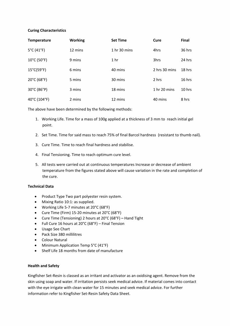
Curing Characteristics
Temperature Working Set Time Cure Final
5°C (41°F) 12 mins 1 hr 30 mins 4hrs 36 hrs
10°C (50°F) 9 mins 1 hr 3hrs 24 hrs
15°C(59°F) 6 mins 40 mins 2 hrs 30 mins 18 hrs
20°C (68°F) 5 mins 30 mins 2 hrs 16 hrs
30°C (86°P) 3 mins 18 mins 1 hr 20 mins 10 hrs
40°C (104°F) 2 mins 12 mins 40 mins 8 hrs
The above have been determined by the following methods:
1. Working Life. Time for a mass of 100g applied at a thickness of 3 mm to reach initial gel point.
2. Set Time. Time for said mass to reach 75% of final Barcol hardness (resistant to thumb nail).
3. Cure Time. Time to reach final hardness and stabilise.
4. Final Tensioning. Time to reach optimum cure level.
5. All tests were carried out at continuous temperatures Increase or decrease of ambient temperature from the figures stated above will cause variation in the rate and completion of the cure.
Technical Data
• Product Type Two part polyester resin system. • Mixing Ratio 10:1: as supplied. • Working Life 5‐7 minutes at 20°C (68°F) • Cure Time (Firm) 15‐20 minutes at 20°C (68°F) • Cure Time (Tensioning) 2 hours at 20°C (68°F) – Hand Tight • Full Cure 16 hours at 20°C (68°F) – Final Tension • Usage See Chart • Pack Size 380 millilitres • Colour Natural • Minimum Application Temp 5°C (41°F) • Shelf Life 18 months from date of manufacture
Health and Safety
Kingfisher Set‐Resin is classed as an irritant and activator as an oxidising agent. Remove from the skin using soap and water. If irritation persists seek medical advice. If material comes into contact with the eye irrigate with clean water for 15 minutes and seek medical advice. For further information refer to Kingfisher Set‐Resin Safety Data Sheet.

Important
The information and data given is based on the experience, research and testing carried out by the manufacturers, Nickerson Chemicals Limited, and is believed to be reliable and accurate. However all recommendations and suggestions are made without prejudice, since the conditions of use are beyond its control. All goods are sold in accordance with our conditions of sale.
SECTION 9.4
WALL TIE SPACING CHART
BRE Recommended Drilling Pattern for 50mm to 75mm Cavity
A – Maximum of 225mm above DPC/ground level B – Vertical maximum 300mm around openings C – 225mm from corners D – Maximum 225mm from opening E – 900mm apart horizontally F – 450mm apart vertically
Remedial Wall Ties