walling 5.1 cast off-site concrete panel walling 5.2 cast on-site
TRANSCRIPT
C&CAA 9
5 WALLING
Various concrete panel walling systems can be used to build aconcrete home. This handbook discusses the two most commonones:
• Cast Off-site Concrete Panel Walling (commonly referred to asprecast wall panels).
• Cast On-site Concrete Panel Walling (commonly referred to astilt-up wall panels).
It also discusses a common variant of the two:
• Concrete Sandwich Panel Walling (which can be manufacturedeither on- or off-site).
5.1 Cast Off-Site Concrete Panel WallingCast off-site concrete panel walling is a form of construction thatis quick and affords the benefits of solid concrete walls at acompetitive price.
In this method, the solid concrete panels are cast in moulds on a level surface (usually a smooth steel base) in quality-controlledfactories away from the building site. The panels are then left tocure to the appropriate level of strength. Once cured, they arestripped from the moulds, lifted into storage areas, andtransported to the site only when they’re needed.
The concrete panels are installed with a mobile crane, which lifts the panels from the transport trailers directly into their finalpositions. The panels can be temporarily braced until a sufficientnumber are installed to form a self-supporting braced structure.
Panel thicknesses usually range from 150 mm to 250 mm.
5.2 Cast On-Site Concrete Panel WallingCast on-site concrete panel walling is also a quick and cost-effective method of construction. In this method, the solidconcrete panels are cast within the formwork on a suitable levelsurface at the building site (often another panel). After curing, themoulds are removed, and a mobile crane is used to lift, tilt andmove the panels directly into their final positions. The panels canbe temporarily braced until a sufficient number are installed toform a self-supporting braced structure.
Panel thicknesses usually range from 150 mm to 250 mm.
Though this method involves more site congestion than cast off-site walling, it also requires less equipment and expertise.Because the panels are always at or near ground level, traditionaltechniques for finishing pavement work can be used. It requiresonly simple formwork, the panel reinforcement can be basic.Panels can be cast on top of one another (“stack-cast”) toeconomise on space, and to use panel surfaces as casting beds for other panels.
5.3 Concrete Sandwich Panel WallingConcrete sandwich panel walling is a variation of on-site and off-site cast concrete panel walling. In this method, an insulation layeris “sandwiched” between two layers of concrete veneer. Concretesandwich panel walling has all the advantages of on- and off-sitecast walling, but is even more thermally efficient as it combines ahigh level of thermal insulation capacity with high thermal mass ofthe concrete.
Panels generally range from 180 mm to 280 mm in thickness.
Concrete sandwich panels are manufactured and installed in themuch same way as on- and off-site cast concrete wall panels,with a few differences:
• The panels are cast in two stages, not one:– The off-form or external face of the panel is cast first,then the insulation board is installed onto the off-formconcrete layer. (The actual insulation material may varydepending on the particular proprietary sandwich panelsystem being used.) – A second concrete layer is then cast on top of theinsulation board to enclose it and finish off the panel.
• The internal layer of concrete is load-bearing and provides thestructural capacity of the panel, while the external layer is notload bearing.
There are proprietary sandwich panel systems available inAustralia.
As with all concrete walling systems, an optimum result willdepend on thorough planning and practical design. Don’t hesitateto consult with architects, designers, engineers and recognisedconcrete panel manufacturers, who can advise you on theparticular needs of your project.
5.4 Internal Walling
5.4.1 Studwork WallingStudwork walls are a typical internal walling system in concretepanel homes, and can be constructed out of either steel or timberframing. These walls must be designed according to the TimberFraming Manual (for timber stud walls) or the specifications of thesteel-stud manufacturer (for steel framed walls), as well as inaccordance with the Building Code of Australia. Studwork wallscan be either constructed on site, or prefabricated in a factory.Construction methods are the same as for brick-veneer or otherclad homes.
Concrete nails or masonry anchors can be used to connectstudwork walls to concrete panel walls and to the floor slab.Shear walls must be anchored with “hold-down masonryanchors”, as detailed in the relevant codes.
Internal stud walls have a number of advantages:
• They can be constructed using standard trades.• They are easy to pass services through.• They can be altered later (if necessary) with less effort.• They are fast and cost-effective to build.• Their lightweight components make installing them easier.
5.4.2 Concrete Block Masonry WallingConcrete blocks can be used to construct internal walls, whetherthey be shear walls, non load-bearing, or structural. These wallsmust be designed and constructed according to the CMAAMasonry Design Manual, as well as the Building Code of Australia.For masonry wall to concrete panel wall connection details, it iscommon to use brick ties (as per the manufacturer’s and thecode’s specifications). The use of concrete blocks for internalwalls offers the following advantages:
• More solid construction• Lower maintenance• Quieter rooms
5.4.3 Concrete Panel WallingUsing concrete panels for internal walls has a number ofadvantages over other building materials:
• Faster construction• More solid construction• Lower maintenance• Quieter rooms
For details on fixing internal walls to base footings, refer to Figures6.5 & 6.6. For details on connecting internal wall panels toexternal walls, refer to Figures 6.9, 6.10 & 6.11.
5.5 Service DetailingThere are two groups of services to take into account whenplanning a concrete panel home: plumbing, electrical/communications and air-conditioning/HVAC.The reticulation of the services can become difficult if insufficient consideration andplanning is not undertaken during the early stages of planning.
In conventional lightweight walling systems, services can betreated almost as an afterthought, as they are usually installed in the wall cavities of the timber stud-work frames. Large openingsfor air-conditioning ducts can simply be cut out of a wall once it’sup. Bricks can be ‘punched-out’ to accommodate an air-conditioning unit. These methods are possible because the wall structure is non-load bearing, and not a solid shell as inconcrete panel homes.
Services can be accommodated in a concrete panel home, butthey must be planned for from the early stages.
5.5.1 Plumbing, Electrical and Communication ServicesServices should be planned in the early stages of the design,before the concrete panels are cast. Plumbing, electrical andcommunication services can be hidden within the wall withouttaking up much space.
If possible, plan the positions of these services when you plan anddetail the concrete wall panels, so that blockouts and recessescan be formed into them as they are cast. Polystyrene blocks canbe used to recess the face of the panels, or to create openings orconduits can be cast in the panel for the services to passthrough. This method is relatively cost-effective, and will result in a level finish on the face of the panel onto which the internal wall-lining material can be directly fixed or battened onto the panel.
Often, though, it’s impractical to plan and detail the plumbingservices to such a degree so early. In that case:
• You can decide to fix the services directly onto the face of thepanels, which requires little planning until installation itself. Thismethod is similar to what is usually done with a masonry orbrick wall. Pipes can be concealed in the cavity formed by abattened fixed internal wall lining. This cavity can be insulatedto make the installation more energy-efficient.
• As long as only a few services are required in a particularpanel, you can chase out the face of the panel and install theservices in the cavity, leaving the surface flush. This methodcan be expensive and time-consuming, and should only beused if there is no other option. Typically, a diamond-impregnated saw blade is used to make cuts along the recessarea, leaving thin blades of concrete to be chiselled out(though it can be very difficult to chase out a panel near itsedges or internal corners, because of the difficulty of getting asaw cutter into those areas). Such chasing should not exceed30 mm in depth and width. Discuss any plans for chasing outrecesses with your designer or consultant engineer, to ensurethat they do not compromise cover and exposure criteria.
• You can accommodate electrical or communications wiringbehind the skirting boards or doorway architraves. (This mayrequire larger sections, so that a recess can be providedbehind the skirting board or architrave to contain the services,with switches and outlets fixed directly onto them). This resultsin the wall panels not requiring any additional work performedon them.
5.5.1.1 Australian Standard AS 3600Australian Standard AS 3600 (Sections 5.11 and 5.12) describesrecesses and chases for services within a wall, and their effect onthe fire-resistance periods for structural adequacy, integrity andinsulation.
5.5.2 Air Conditioning / HVACDucted heating and cooling can be placed either internally (in the ceiling or roof space) or externally (adjacent to the wall panel).Large openings in the panels may be required for the ducting. It is best to decide the locations of the duct openings before thepanels are manufactured, so that the openings can be cast intothe panels. Although you can saw-cut or core drill openingsthrough the panels later.
If you do decide to drill openings later, you can use a diamond-impregnated core bit to create core holes with diameters of up to 300 mm. Although any cutting or coring will normally berelatively expensive.
Make sure the designer or consultant engineer approves yourplans before you cut or core any panel.
5.6 Opening Details (Windows and Door Openings)Openings for windows and doors in concrete panel walls can be simply detailed to accommodate either timber or aluminiumframes. The edge detail around the panel opening is similar to that used with cavity brick or block walls. It is often easier toinstall window and door frames into concrete wall panels than into other conventional walling systems, because the panelsprovide a uniform, solid structure onto which to fasten the frame.
Once the openings are detailed to provide the required edgeprofiles for the heads, jambs and sills, the frames are made tomeasure, either from the panel shop drawings or from on-sitemeasurements of each of the openings. Alternatively, standardprefabricated window and door frames can be specified, and thepanel openings sized to accommodate these frames. There is awide variety of prefabricated window and door frames to choosefrom; your supplier can help you make an appropriate choice.
The remainder of this section discusses the usual processesinvolved in detailing the surrounds of openings meant foraluminium or timber-framed windows and doors. (Individual frametypes and their particular installation processes should bediscussed with the frame supplier and installer).
5.6.1 General Considerations for OpeningsDetailing window or door openings begins with determining theirsize and location. It’s best if an opening is located entirely within asingle wall panel; otherwise, small differential movements betweenpanels can later cause weatherproofing problems in nearby joints.Keeping the openings within single panels also enables theopenings to be made with greater accuracy.
Whether you plan on using aluminium or timber frames, theprinciples for detailing openings in the wall panels (including thereveal profiles for the sills, jambs and headers) are essentially the same.
10 C&CAA
11C&CAA
5.6.1.1 Opening SizingIn determining size of the opening, take all of the following intoconsideration:
• The size of the external window frame. The manufacturing tolerance in producing the opening in thewall panel.
• The method and type of installation, which will determine theamount of clearance that needs to be added to the overallopening to enable the frame to be installed. Prefabricatedframes are cheaper, but require greater clearances in theopening to enable installation. Made-to-fit frames provide abetter fit, but require on-site measurements of the openingbefore the frame can be made. This is initially more expensive,but results in a better-fitting windows and doors, and thereforefewer problems with prefabricated frames not fitting openings.
• Whether cast off-site panels will be used, in which case it maybe possible to install the frames into the wall panels while theyare in storage in the factory, thereby reducing on-siteconstruction time. Some types of door frames, such as press-metal frames, can actually serve as formwork as they’re castinto the panel, saving the time and expense in fitting themafterwards. To do this, though, you will have to decide on thefinal locations of the openings from the start, as it will hardly be possible to move them later.
5.6.1.2 Reveal ProfilesConsiderations for reveal profiles of the window and door openings:
• The void former or type of formwork used to block out theopening in the panel. The type of material and its level of finishwill directly determine the finish of the opening’s reveal surface.If the reveal surface of the opening is to be left as off-form, orcoated only with a flat (low build) paint, imperfections on thereveal surface will be visible unless the forms are of good-quality ply or steel. Joints along the void former or formworkshould be in line, not stepped. Ideally, the joints should besealed to keep the concrete from leaking. If the reveal is to befinished with a high build coating, though, or lined with amaterial like tile or timber, it may be sufficient to use formworkwith a rougher surface, and/or polystyrene void formers toblock out openings. This will reduce costs, especially foropenings that aren’t repeated elsewhere.
• It is recommended that all surfaces of the reveals (except thesill) are perpendicular to the main surface of the panel, so thatthe opening can be formed easily, and so that there will be asquare surface to attach the frame to. The sill profile shouldhave a fall toward the external face of the panel to allow rain todrain away. Take care to design the formwork so that it can bestripped from the panel without damaging either the panel orthe form. That usually means that the formwork must becollapsible (that is, able to be stripped from the panel insections). Void-formers made of cheap materials (such aspolystyrene) are dispensable; they can simply be destroyedduring stripping if need be.
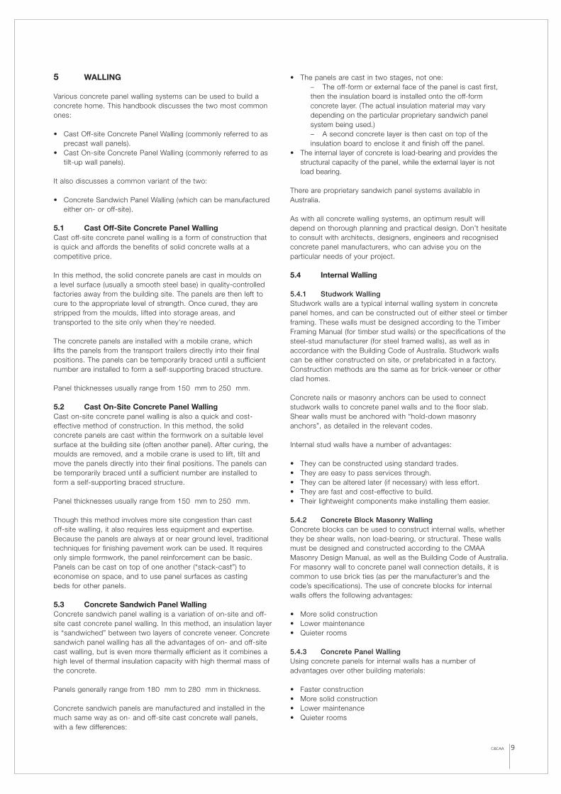
• Rebates can also be cast into the reveals of the openings. It isrecommended that a “drip groove” be cast into the head of thewindow or door opening to catch rain water running back intothe opening. A drip groove can easily be formed by aprefabricated timber or plastic fillet strip. The drip grooveshould be 10 to 15 mm deep, and should extend along the fulllength of the head reveal. Ideally, the groove should be locatedhalfway between the external edge of the reveal and theexternal face of the frame, but at a minimum distance of 30mm from the external edge of the reveal. Ideally the frameshould be set back as far as possible from the external face of the panel so as to maximise protection from the weather.
• Always finish off the external and internal edges of the revealswith either a “pencil-round” detail (preferred for ease andsimplicity) or a chamfer (bevel) detail. A square sharp edge is more likely to be chipped or damaged, and is therefore not recommended.
FLASHING SEALED TO CONCRETE PANELAND FRAMING
INTERNAL LINING
DRIP GROOVE
CONCRETE WALL PANEL
HEAD DETAIL
JAMB DETAIL
SILL DETAIL
SEALANT SHIMMING/PACKING
INTERIOR LINING
INTERNAL LINING
SHIMMING/PACKING
POSITION FRAMING TO ALLOW DRAINAGE FROM WITHIN
FLASHINGTILED SILL (IF REQUIRED)
Figure 5.1 Typical Window Header, Jamb and Sill Details.(Based on Aluminium Window Details from C&CANZ,Residential Concrete Detailing and Specification Guide.)
12 C&CAA
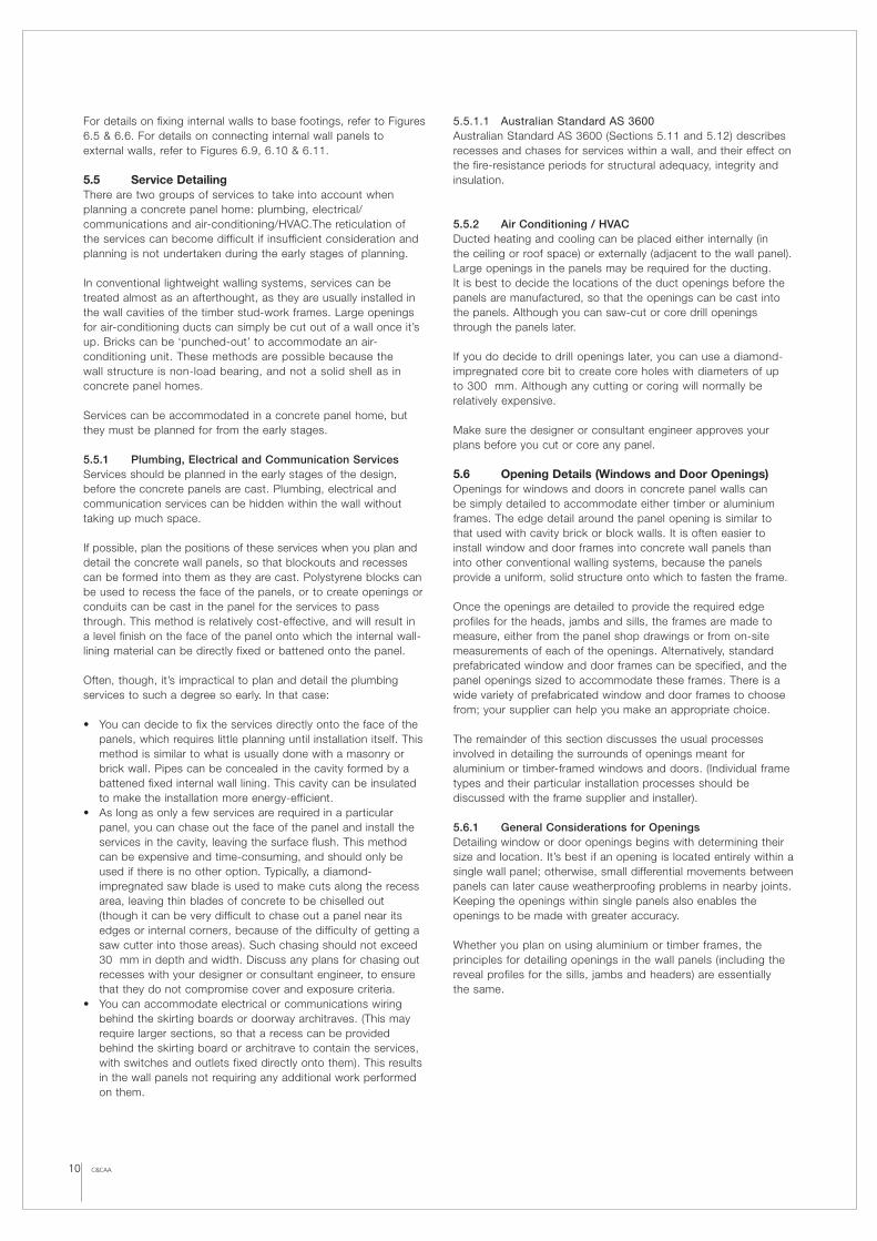
Installing a window or door frame into a concrete panel is similarto installing one into a brick or block-work wall. The frame isinserted into the opening and shimmed to level, then fasteneddirectly to the concrete panel reveals. Proprietary flashing, sealsand trims are installed and fastened onto the frame or panelreveals to complete the window or door arrangement. (Actualinstallation procedures vary, depending on the particular windowsupplier and installer.)
Avoid details that require frame-fixing inserts to be cast into thereveals of the panel opening. Cast-in fixings complicate themanufacture of the panel and raise the cost, and they are difficult to position accurately. Instead, whenever possible use connectiondetails that require fixings to be drilled into the panel after it hasbeen cast.
DOOR LEAF
CONCRETE WALL PANEL
PRESS METAL DOOR FRAMECAST INTO PANEL
JAMB/HEADER DETAIL
(ALTERNATIVELY, TIMBER TRIMMING CAN BE USED IN LIEU OF PRESS-METAL FRAME).
FLOOR COVERING
PAVING LEVEL
REINFORCED CONCRETE SLAB
SILL DETAIL
SILL FLASHING
75 m
m m
in.
RECESSED TIMBERDOOR AND SILL
ALUMINIUM DOOR FRAME
SHAPED TIMBER ON OPC
PAVING LEVEL
SILL FLASHING REINFORCED CONCRETE SLAB
SILL DETAIL
75 m
m m
in.
Figure 5.2 Typical Door Header, Jamb and Sill Details. (Sill Detailsare based on Aluminium and Timber Door Sill Details fromC&CANZ, Residential Concrete Detailing and Specification Guide.)

C&CAA 13
6 CONNECTIONS
The concrete wall panels that make up a concrete panel homemust be stabilised and supported so that they can carry verticalloads and resist lateral loads. This stability and support is usuallyprovided by the panel connections, and their associated fixings toother panels and to external supporting members (such asfootings, ground slabs, or framing/bracing supports).
Connection types and their detailing should be chosen witheconomy in mind, but must be appropriate for its role in stabilisingand supporting the concrete wall panels.
6.1 Design ConsiderationsConnections can be fixed by grouting dowels in core holes in thepanels, bolted connection systems, welded connection systems,or a combination of these.
Welded connections systems are simpler to implement and havecleaner lines, but care must be taken to avoid locking up thejoints and preventing further movement. Bolted systems are lesslikely to cause this problem, but are usually more complicated toimplement, as tolerances must be allowed for when placingconnection plates, brackets, bolt holes, and so on. They generallyalso occupy more space than welded connections.
The design and detailing of connections for a concrete panelhome should ensure a good level of buildability, load capacity and ductility. When designing connections, take into account:
• In-service loads (such as dead, live, or wind loads).• Construction loads (such as lifting or bracing loads).• Thermal gradients (such as expansion and contraction of the
panel, and the degree of bowing).• Fire performance.• Earthquake requirements.• Complexity of the connection (Keeping the fixing as simple
as possible will reduce costs.).
More than one level of fixing is normally required to stabilise apanel. Typically, a panel requires two load-bearing connections at the base, and two lateral restraining connections at the top-butthese requirements may vary, depending on the panel’s design,shape and size.
The dimensions of the panels, and of the structure itself, shall varywithin a specified tolerance, so connections should be designedwith this in mind. Connections should also allow the panel to flexor move in response to temperature fluctuations and applied loads.
Permanent steel connections, especially those that are exposed tothe external environment, should be protected against corrosion.Any protective coating should be applied over the entire fixing,including those parts that are cast into the concrete. Examples of such coatings are:
• Hot-dipped galvanising.• Priming and painting with an appropriate corrosion-protective
paint system.• Encasing the components in concrete to an appropriate cover.
Fixings may also require protection against fire. Whenever a wallpanel must be fire-rated in accordance with the BCA, thesupporting fixings of that panel must also be fire-rated to thatlevel. This requirement is usually met by encasing the fixings in thepanel. As per AS 3600, a minimum cover of 20 mm is required toprovide 60 minutes of fire resistance (the normal fire resistanceperiod for a class-1 residential home).
6.2 Types of FixingsThere are three main types of fixings used in concrete panelhomes:
• Dowel and direct-bearing fixings • Bolted fixings • Welded fixings
6.2.1 Dowel and Direct Bearing FixingsIn these fixings, steel dowels restrain and stabilise the panel,which bears directly onto a footing, ground slab, or lower wallpanel (if the fixing is on an upper storey).
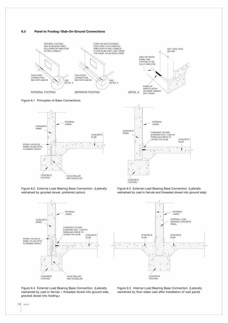
This type of fixing is used at the base of a wall panel to quicklyposition it before final alignment and grouting. The panel initiallybears on dense, compressible packers or shims (usually of denseplastic) to the correct levels. (Steel packers or shims should notbe used, as they do not provide suitable compression capabilities,and may lead to future corrosion problems.) There should be onlytwo bearing pads per panel, located at a minimum of 300 mmfrom either end of the panel. These pads will carry the panel’sdead and live vertical loads until the bottom edge of the panel isgrouted up (or “dry-packed”) to provide uniform distribution of theloads down to the footings, ground slab or lower panels. (Refer toFigures 6.2, 6.4, 6.6, and 6.8 for details.)
6.2.2 Bolted FixingsBolted fixings usually consist of cast-in ferrule inserts in thepanels, and steel fixing brackets or plates that can be bolted tothe ferrules (or threaded dowel bars that can be attached tothem). These fixings, depending on their particular design, canprovide a panel with both lateral restraint and load-bearing (shear)capacity. They are usually the most flexible, easiest to install, andleast costly of the three types of connections, but installing themeffectively and efficiently requires good detailing. The mainconcern with this type of connection is accommodating tolerancesfor misalignment of the insert in the panel, the panel itself and thesupporting structure. The overall encroachment of the connection(fixing plate, bracket, bolt head, etc into the living space may alsobe a concern. This can be resolved by recessing the fixing intothe panel. (Refer to Figures 6.3, 6.4, 6.7, 6.8, 6.9, 6.10, 6.11, 6.12, 6.13, 6.16, 6.17, and 6.18 for details.)
6.2.3 Welded FixingsWelded fixings consist of cast-in steel weld plates that are weldeddirectly to other steel weld plates or brackets. While weldedfixings are perhaps the simplest to install, they are usually themost costly, because of:
• The large cast-in weld plates, which have to be purpose-made.• The need for a qualified and experienced welder on-site during
panel installation.• The extra installation time needed to weld the fixing plate or
bracket in place.
This type of fixing should only be used when no other type issuitable. (Refer to Figure 6.15 for details.) They rely on the weldtaking all the load and ensuring a quality weld has been producedon-site may be difficult to guarantee.
Mechanical fixings, such as drill-in mechanical expansion anchors,should not be used to support or stabilise panels unless they havebeen approved by the design or consultant engineer for the project.
A selection of proven connections for various standard situationsare described in the following sections and should be used as aguide to assist with individual design and detailing of connections.
14 C&CAA
INTERNALLINING
INTERNAL LOADBEARING CONCRETEPANEL
CONCRETESLAB
CONCRETESLAB
CONCRETEFOOTING
INTERNALLINING
HOLE DRILLEDAND DOWELLED
DOWEL HOLES INPANEL FILLED WITHFLOWABLE GROUT
THREADED TIE BARSCREWED INTO CAST-INFERRULES PRIOR TOLAYING THE SLAB CONCRETE
SLAB
CONCRETEFOOTING
CONCRETEPANEL
6.3 Panel to Footing / Slab-On-Ground Connections
Figure 6.1 Principles of Base Connections
Figure 6.2 External Load Bearing Base Connection. (Laterallyrestrained by grouted dowel, preferred option)
Figure 6.3 External Load Bearing Base Connection. (Laterallyrestrained by cast-in ferrule and threaded dowel into ground slab)
Figure 6.4 External Load Bearing Base Connection. (Laterallyrestrained by cast-in ferrule + threaded dowel into ground slab,grouted dowel into footing.)
Figure 6.5 Internal Load Bearing Base Connection. (Laterallyrestrained by floor slabs cast after installation of wall panel)
INTEGRAL FOOTINGAND SLAB BASE FIRST,FOLLOWED BY ERECTIONOF WALL PANELS
STRIP OR PAD FOOTINGSCAST FIRST, FOLLOWED BYERECTION OF WALL PANELS.FLOOR SLAB CAST LAST USINGTHE PANEL AS AN EDGE-FORM
TWO-POINTCONNECTIONSEE NOTE ABOVE
TWO-POINTCONNECTIONSEE NOTE ABOVESEE
DETAIL ASEE DETAIL A
SHIMS OF HARD PLASTICOR FIBRE CEMENT(NOT STEEL)INTEGRAL FOOTING SEPARATE FOOTING DETAIL A
AREA BETWEENPANEL AND FOOTING TO BE FULLY GROUTED
NOT LESS THAN 300 MM
THREADED TIE BARSCREWED INTO CAST-INFERRULES PRIOR TOLAYING THE SLAB
INTERNALLINING
CONCRETESLAB
CONCRETEFOOTING
CONCRETEPANEL
CONCRETESLAB
CONCRETEFOOTING
CONCRETEPANEL
INTERNALLINING
HOLE DRILLEDAND DOWELLED
DOWEL HOLES INPANEL FILLED WITHFLOWABLE GROUT
C&CAA 15
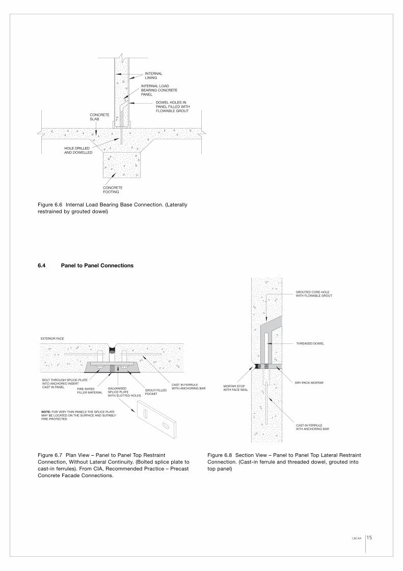
EXTERIOR FACE
NOTE: FOR VERY THIN PANELS THE SPLICE PLATEMAY BE LOCATED ON THE SURFACE AND SUITABLY FIRE-PROTECTED
CAST IN FERRULE WITH ANCHORING BAR
GROUT-FILLED POCKET
BOLT THROUGH SPLICE-PLATE INTO ANCHORED INSERT CAST IN PANEL
FIRE-RATED FILLER MATERIAL
GALVANISED SPLICE PLATE WITH SLOTTED HOLES
INTERNALLINING
INTERNAL LOADBEARING CONCRETEPANEL
CONCRETESLAB
CONCRETEFOOTING
HOLE DRILLEDAND DOWELLED
DOWEL HOLES INPANEL FILLED WITHFLOWABLE GROUT
Figure 6.6 Internal Load Bearing Base Connection. (Laterallyrestrained by grouted dowel)
6.4 Panel to Panel Connections
CAST-IN FERRULE WTH ANCHORING BAR
DRY-PACK MORTARMORTAR STOP WITH FACE SEAL
THREADED DOWEL
GROUTED CORE-HOLE WITH FLOWABLE GROUT
Figure 6.7 Plan View – Panel to Panel Top RestraintConnection, Without Lateral Continuity. (Bolted splice plate tocast-in ferrules). From CIA, Recommended Practice – PrecastConcrete Facade Connections.
Figure 6.8 Section View – Panel to Panel Top Lateral RestraintConnection. (Cast-in ferrule and threaded dowel, grouted intotop panel)

16 C&CAA
SEALANT
PRE-FABRICATEDPLATES SITE FIXED TOTOP OF PANELS
SEALANT
FILLER
FILLER
PRE-FABRICATEDPLATES SITE FIXED TOTOP OF PANELS
Figure 6.9 Plan View – Panel to Panel Top Corner Restraint.(Recessed angle bracket, bolted to cast-in ferrules to internalback face of panels)
Figure 6.10 Plan View – Panel to Panel Top Corner, L-PlateRestraint. (Plate bolted to cast-in ferrules to top reveal faces of panels)
Figure 6.11 Plan View – Panel to Panel Top Corner T-PlateRestraint. (Plate bolted to cast-in ferrules to top reveal faces of panels)
FOR MAXIMUM TOLERANCE,CONNECTING ANGLE SHOULDHAVE HORIZONTAL AND VERTICAL SLOTTED HOLES
ANGLE BOLTED TOANCHORED FERRULESCAST IN THE PANELS
POCKET FORMEDIN PANEL AND LATERFILLED WITH GROUT.ANGLE MAY BESURFACE-MOUNTEDDEPENDING ON FIRE REQUIREMENTS,ANGLE SIZE AND THICKNESS OF BATTENS
FILLER ANDSEALANT(FIRE-RATEDIF REQUIRED)
INTERNAL LINING
TYPICAL CONNECTION DETAIL
WHEN EITHERWALL IS NOTTOP-BRACEDEACH CAN ACTTO BRACETHE OTHER
WHEN ONE WALL ISTOP-BRACED (BY ROOF-TRUSSESFOR EXAMPLE) END WALLS MAYBE TOP BRACED OFF THIS
EXAMPLES OF WHERE REQUIRED
17C&CAA
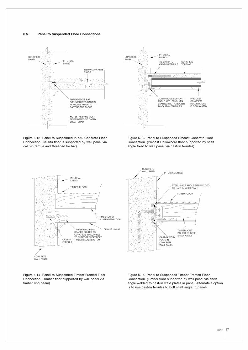
TIE BAR INTOCAST-IN FERRULE
INSITU CONCRETEFLOOR
CONCRETEPANEL
CONCRETE TOPPING
PRE-CAST CONCRETE HOLLOWCOREFLOOR SYSTEM
CONCRETEPANEL
THREADED TIE BARSCREWED INTO CAST-INFERRULES PRIOR TOCASTING THE FLOOR
CONTINUOUS SUPPORTANGLE WITH 80MM MINBEARING WIDTH, BOLTED TO CAST-IN FERRULES
NOTE: THE BARS MUSTBE DESIGNED TO CARRYSHEAR LOAD
INTERNALLINING
INTERNALLINING
TIMBER JOIST SUSPENDED FLOOR
CAST-INFERRULE
TIMBER RING BEAMBEARER BOLTED TOCONCRETE WALL PANELTO SUPPORT SUSPENDEDTIMBER FLOOR SYSTEM
CEILING LINING
TIMBER FLOOR
INTERNALLINING
CONCRETEWALL PANEL
INTERNAL LINING
TIMBER FLOOR
TIMBER JOISTBOLTED TO STEELSHELF ANGLE
CAST-IN WELD PLATE IN CONCRETEWALL PANEL
STEEL SHELF ANGLE SITE-WELDEDTO CAST-IN WELD PLATE
CONCRETEWALL PANEL
6.5 Panel to Suspended Floor Connections
Figure 6.12 Panel to Suspended In-situ Concrete FloorConnection. (In-situ floor is supported by wall panel via cast-in ferrule and threaded tie bar)
Figure 6.13 Panel to Suspended Precast Concrete FloorConnection. (Precast Hollowcore floor supported by shelf angle fixed to wall panel via cast-in ferrules)
Figure 6.14 Panel to Suspended Timber-Framed FloorConnection. (Timber floor supported by wall panel via timber ring beam)
Figure 6.15 Panel to Suspended Timber Framed FloorConnection. (Timber floor supported by wall panel via shelfangle welded to cast-in weld plates in panel. Alternative optionis to use cast-in ferrules to bolt shelf angle to panel)
18 C&CAA
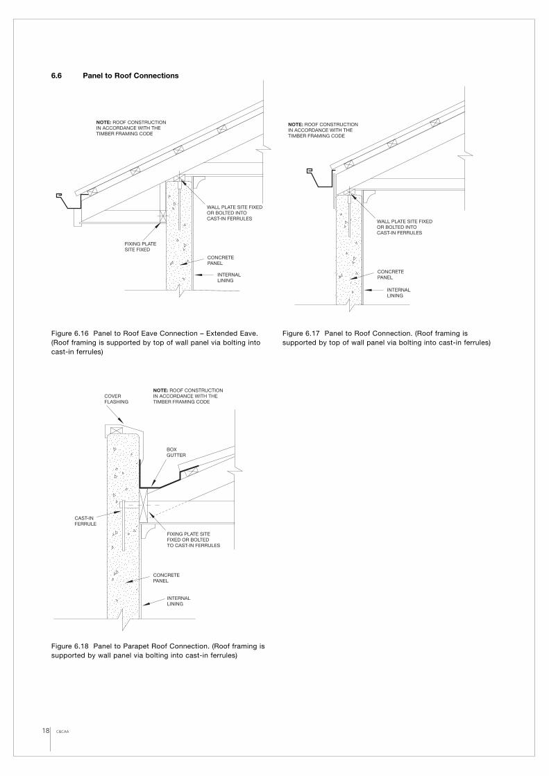
FIXING PLATESITE FIXED
CONCRETEPANEL
NOTE: ROOF CONSTRUCTIONIN ACCORDANCE WITH THE TIMBER FRAMING CODE
WALL PLATE SITE FIXEDOR BOLTED INTO CAST-IN FERRULES
INTERNALLINING
CONCRETEPANEL
NOTE: ROOF CONSTRUCTIONIN ACCORDANCE WITH THE TIMBER FRAMING CODE
WALL PLATE SITE FIXEDOR BOLTED INTO CAST-IN FERRULES
INTERNALLINING
COVER FLASHING
CONCRETEPANEL
CAST-INFERRULE
FIXING PLATE SITEFIXED OR BOLTEDTO CAST-IN FERRULES
NOTE: ROOF CONSTRUCTIONIN ACCORDANCE WITH THE TIMBER FRAMING CODE
BOXGUTTER
INTERNALLINING
6.6 Panel to Roof Connections
Figure 6.16 Panel to Roof Eave Connection – Extended Eave.(Roof framing is supported by top of wall panel via bolting intocast-in ferrules)
Figure 6.17 Panel to Roof Connection. (Roof framing issupported by top of wall panel via bolting into cast-in ferrules)
Figure 6.18 Panel to Parapet Roof Connection. (Roof framing issupported by wall panel via bolting into cast-in ferrules)
7 PANEL JOINTING
The joints between adjoining panels have an effect on the cost,performance, and aesthetics of the final structure have alwaysbeen an inherent issue with concrete panel walling systems.
Panel joints divide the wall into manageable panel units formanufacture, transport and installation. They provide a means foraccommodating differential and temperature movements betweenthe panels. They can also be designed to take up any clearance,construction or installation tolerances.
7.1 General Joint Design ConsiderationsThe joints are usually the least weatherproof and fireproof parts ofthe wall panel system. Take particular care to ensure that they arecompatible with the structural design, the erection procedures,and the fixing details. Bad joint arrangements cannot be easilyfixed by good joint detailing.
The number of joints should be kept to a minimum. If a smallpanel appearance is desired, this can be achieved by using“dummy joints” (or grooves) in the panel surface to mimic extrajoints. Chamfers at the edges of the panels reduce the possibilityof damage to the edge, but as they soften the line of the paneledge, they will provide greater tolerances in masking misalignmentin the panel joints.
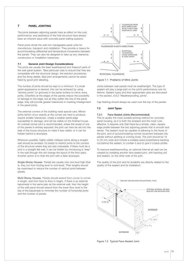
The external corners of the building need special care. Mitredjoints (which occur exactly at the corner) are hard to produce,require smaller tolerances, create a weaker panel edgesusceptible to damage, and will be visible on the finished house.An oversail corner joint is recommended, where the reveal of oneof the panels is entirely exposed; the joint can then be set into theside of the house structure to make it less visible, or it can behidden behind a downpipe.
Wherever possible, highly-visible midspan joints along a straightwall should be avoided; it’s better to restrict joints to the cornersof the structure where they are less noticeable. If there must be ajoint in a straight flat wall, it can be hidden by introducing a “step”in the wall (though this will change the layout of the floor plan).Another option is to hide the joint with a false downpipe.
Single-Storey Houses Panels are usually only one level high (thatis, they run from footing-level to roof-level). Their lengths shouldbe maximised to reduce the number of vertical joints betweenpanels.
Multi-Storey Houses Panels should extend from corner to cornerin length, and from floor-to-floor in height. If there is an externalbalustrade in the same plan as the external wall, then the heightof the wall panel should extend from the lower floor level to thetop of the balustrade to minimise the number of horizontal jointsand the number of panels.
Figure 7.1 Problems of Mitre Joints
Joints between wall panels must be weathertight. The type ofsealant will play a large part on the joint’s performance over itslifetime. Sealant types and their appropriate uses are discussed in the section, 8.8.2 “Weatherproofing Joints”.
Cap flashing should always be used over the top of the panels.
7.2 Joint Types
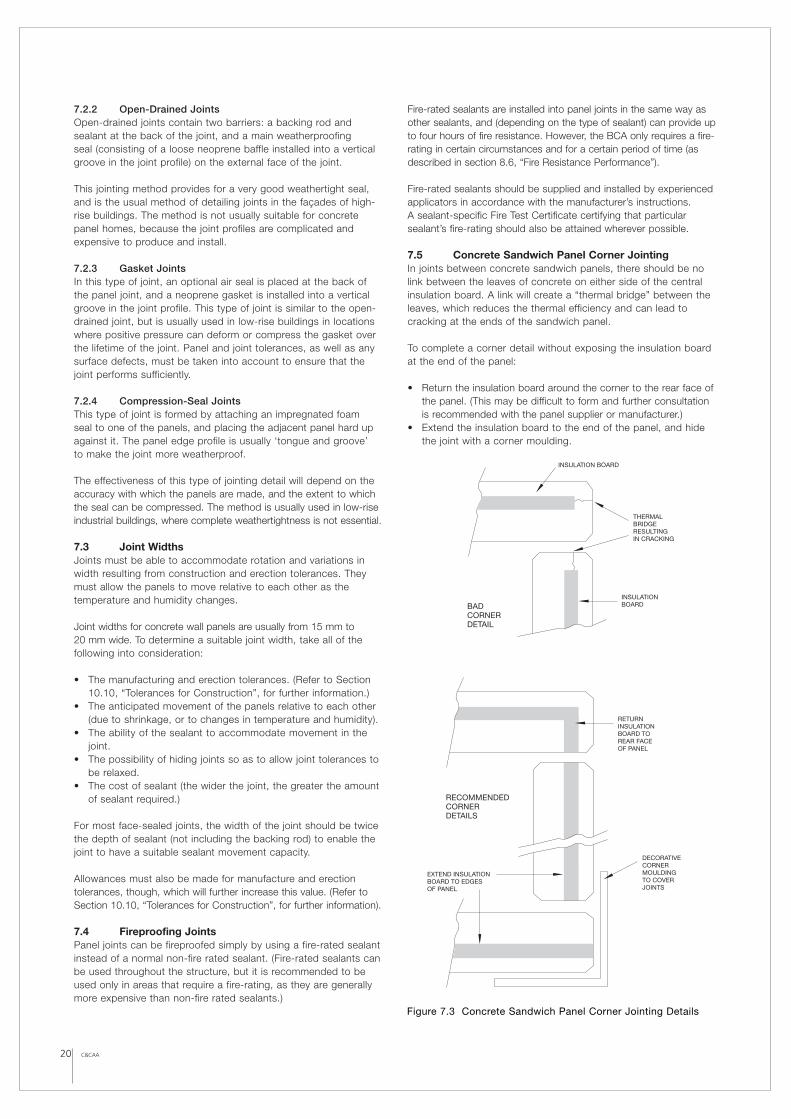
7.2.1 Face-Sealed Joints (Recommended)This is usually the most suitable jointing method for concretepanel housing, as it is both the simplest and the most cost-effective. It requires only that there be a simple, clean, square-edge profile between the two adjoining panels that is smooth anddense. The sealant must be capable of adhering to the faces ofthe joint, and of accommodating normal movement between thepanels without splitting or coming loose. The joint should be 15 to 20 mm wide and include a suitably-sized polyethylene backingrod behind the sealant, to contain it and to give it a back profile.
To improve weatherproofing, an optional internal air seal can becreated by installing another face-sealed joint, with backing rodand sealant, on the other side of the joint.
The quality of the joint and its durability are directly related to thequality of the sealant and its installation.
Figure 7.2 Typical Face-Sealed Joint
19C&CAA
TOLERANCES FROM BOTH DIRECTIONSAFFECT WIDTH AND POSITION OF JOINT
ROTATIONAL TOLERANCES
ROTATIONAL TOLERANCES CAUSE VARIATIONS IN JOINT WIDTH
TOLERANCES IN BOTH DIRECTIONS
OPTIONAL INTERNAL AIR SEAL(SEALANT AND BACKING ROD)
SEALANT AND BACKING ROD (EXTERNAL FACE)
15-20 mm
INTERIOR
EXTERIOR
7.2.2 Open-Drained Joints Open-drained joints contain two barriers: a backing rod andsealant at the back of the joint, and a main weatherproofing seal (consisting of a loose neoprene baffle installed into a verticalgroove in the joint profile) on the external face of the joint.
This jointing method provides for a very good weathertight seal,and is the usual method of detailing joints in the façades of high-rise buildings. The method is not usually suitable for concretepanel homes, because the joint profiles are complicated andexpensive to produce and install.
7.2.3 Gasket Joints In this type of joint, an optional air seal is placed at the back ofthe panel joint, and a neoprene gasket is installed into a verticalgroove in the joint profile. This type of joint is similar to the open-drained joint, but is usually used in low-rise buildings in locationswhere positive pressure can deform or compress the gasket overthe lifetime of the joint. Panel and joint tolerances, as well as anysurface defects, must be taken into account to ensure that thejoint performs sufficiently.
7.2.4 Compression-Seal Joints This type of joint is formed by attaching an impregnated foam seal to one of the panels, and placing the adjacent panel hard upagainst it. The panel edge profile is usually ‘tongue and groove’ to make the joint more weatherproof.
The effectiveness of this type of jointing detail will depend on theaccuracy with which the panels are made, and the extent to which the seal can be compressed. The method is usually used in low-riseindustrial buildings, where complete weathertightness is not essential.
7.3 Joint WidthsJoints must be able to accommodate rotation and variations inwidth resulting from construction and erection tolerances. Theymust allow the panels to move relative to each other as thetemperature and humidity changes.
Joint widths for concrete wall panels are usually from 15 mm to 20 mm wide. To determine a suitable joint width, take all of thefollowing into consideration:
• The manufacturing and erection tolerances. (Refer to Section10.10, “Tolerances for Construction”, for further information.)
• The anticipated movement of the panels relative to each other(due to shrinkage, or to changes in temperature and humidity).
• The ability of the sealant to accommodate movement in thejoint.
• The possibility of hiding joints so as to allow joint tolerances tobe relaxed.
• The cost of sealant (the wider the joint, the greater the amountof sealant required.)
For most face-sealed joints, the width of the joint should be twicethe depth of sealant (not including the backing rod) to enable thejoint to have a suitable sealant movement capacity.
Allowances must also be made for manufacture and erectiontolerances, though, which will further increase this value. (Refer toSection 10.10, “Tolerances for Construction”, for further information).
7.4 Fireproofing JointsPanel joints can be fireproofed simply by using a fire-rated sealantinstead of a normal non-fire rated sealant. (Fire-rated sealants canbe used throughout the structure, but it is recommended to beused only in areas that require a fire-rating, as they are generallymore expensive than non-fire rated sealants.)
Fire-rated sealants are installed into panel joints in the same way asother sealants, and (depending on the type of sealant) can provide upto four hours of fire resistance. However, the BCA only requires a fire-rating in certain circumstances and for a certain period of time (asdescribed in section 8.6, “Fire Resistance Performance”).
Fire-rated sealants should be supplied and installed by experiencedapplicators in accordance with the manufacturer’s instructions. A sealant-specific Fire Test Certificate certifying that particularsealant’s fire-rating should also be attained wherever possible.
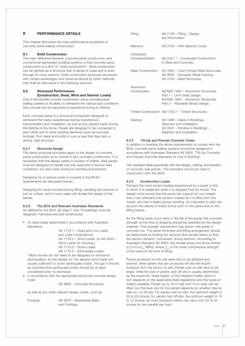
7.5 Concrete Sandwich Panel Corner JointingIn joints between concrete sandwich panels, there should be nolink between the leaves of concrete on either side of the centralinsulation board. A link will create a “thermal bridge” between theleaves, which reduces the thermal efficiency and can lead tocracking at the ends of the sandwich panel.
To complete a corner detail without exposing the insulation boardat the end of the panel:
• Return the insulation board around the corner to the rear face ofthe panel. (This may be difficult to form and further consultationis recommended with the panel supplier or manufacturer.)
• Extend the insulation board to the end of the panel, and hidethe joint with a corner moulding.
20 C&CAA
THERMALBRIDGERESULTINGIN CRACKING
INSULATIONBOARD
INSULATION BOARD
BADCORNERDETAIL
RETURNINSULATIONBOARD TO REAR FACEOF PANEL
DECORATIVECORNERMOULDINGTO COVERJOINTS
EXTEND INSULATIONBOARD TO EDGESOF PANEL
ENDED
RECOMMENDEDCORNERDETAILS
Figure 7.3 Concrete Sandwich Panel Corner Jointing Details
C&CAA 21
8 PERFORMANCE DETAILS
This chapter discusses the main performance properties ofconcrete panel walling construction.
8.1 Solid ConstructionThe main difference between concrete panel construction andconventional lightweight building systems is that concrete panelconstruction is a form of “solid construction”. Solid constructioncan be defined as a structure that is dense in mass and is solidthrough its cross section). Solid construction produces structureswith certain advantages over those produced by other methods,that shall be discussed in the following sections.
8.2 Structural Performance (Construction, Dead, Wind and Seismic Loads)
One of the benefits of solid construction using concrete panelwalling systems is its ability to withstand the various load conditionsthat a house can be expected to experience during its lifetime.
Each concrete panel is a structural component designed towithstand the loads experienced during manufacture,transportation and installation, as well as any applied loads duringthe lifetime of the home. Panels are designed to be connected toeach other and to other building elements (such as concretefootings, floor slabs and roofs) in such a way that they form astrong, rigid structure.
8.2.1 Structural DesignThe same structural principles apply to the design of concretepanel construction as to normal in-situ concrete construction. It isnecessary that the design satisfy a number of criteria. Wall panelsmust be designed to handle not only expected in-service loadconditions, but also loads during its handling and erection.
Designing for in-service loads is covered in the BCA’srequirements (as discussed below).
Designing for loads incurred during lifting, handling and erection isjust as critical, and in most cases will dictate the design of thepanels.
8.2.2 The BCA and Relevant Australian StandardsAs defined by the BCA, all Class 1 and 10 buildings must bedesigned, manufactured and constructed:
• To resist loads determined in accordance with AustralianStandards:
AS 1170.1 – Dead and Live Loads and Load Combinations.AS 1170.2 – Wind Loads. (or AS 4055 –Wind Loads for Housing.)AS 1170.3 – Snow Loads.AS 1170.4 – Earthquake Loads*
* Most homes do not need to be designed to withstandearthquakes, as the design for the applied wind loads areusually sufficient to cover earthquake loads. Though it shouldbe stressed that earthquake loads should be at leastconsidered prior to dismissal.
• In accordance with the appropriate structural concrete designcode:
AS 3600 – Concrete Structures
as well as any other relevant design codes, such as:
Footings: AS 2870 – Residential Slabs and Footings.
Piling: AS 2159 – Piling – Design and Information.
Masonry: AS 3700 – SAA Masonry Code.
Composite Concrete & Steel: AS 2327.1 – Composite Construction
in Steel and Concrete.
Steel Construction: AS 4600 – Cold Formed Steel Structures.AS 3623 – Domestic Metal Framing.AS 4100 – Steel Structures.
Aluminium Construction: AS/NZS 1664 – Aluminium Structures,
Part 1 – Limit State Design.AS/NZS 1664 – Aluminium Structures, Part 2 – Allowable Stress Design.
Timber Construction: AS 1720.1 – Timber Structures.
Glazing: AS 1288 – Glass in Buildings – Selection and Installation.AS 2047 – Window in Buildings – Selection and Installation.
8.2.3 Tilt-Up and Precast Concrete CodesIn addition to meeting the above requirements to comply with theBCA, concrete panel walling systems should be designed inaccordance with Australian Standard AS 3850, “Tilt-Up Concreteand Precast Concrete Elements for Use in Building”.
This standard deals specifically with the design, casting, and erection of concrete wall panels. This standard should be read inconjunction with AS 3600.
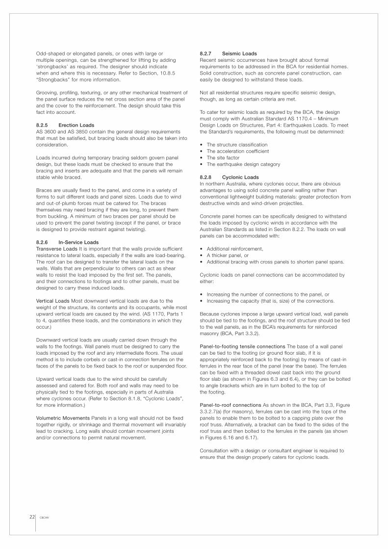
8.2.4 Construction LoadsPerhaps the most severe loading experienced by a panel is that to which it is subjected when it is stripped from its mould. Thedesign must ensure that the panel can support its own weight,that it can withstand the suction created as it is lifted from themould, and that it bears during handling. It’s important to take intoaccount the effects of these forces both on the panel and on thelifting inserts.
As the lifting loads occur early in the life of the panel, the concretestrength at the time of stripping should be specified by the designengineer. This strength requirement may govern the grade ofconcrete mix. The panel thickness and lifting arrangement shouldbe determined by limiting the extreme fibre tensile stress so thatthe section remains “uncracked” during erection. According toAustralian Standard AS 3850, this tensile stress should be limitedto 0.413√ƒcm (MPa), where ƒcm is the mean compressive strengthof the panel at the time of lifting.
Panels produced on-site will need only to be stripped anderected, while panels that are produced off-site will requiretransport from the factory to site. Panels cast on-site tend to belarger, while the size of panels cast off-site is usually determinedby the maximum ‘head height’ of the transport trailer, which inturn depends on the applicable state regulations and the types oftrailers available. Panels up to 15 m high and 10 m wide can belifted, but the best size for the panels depends on whether they’recast on- or off-site. For panels cast on-site, the optimum weight is20 to 25 tonnes; for panels cast off-site, the optimum weight is 10to 12 tonnes, as most transport trailers can carry from 20 to 24tonnes (or two panels) per load.
22 C&CAA
Odd-shaped or elongated panels, or ones with large or multiple openings, can be strengthened for lifting by adding‘strongbacks’ as required. The designer should indicate when and where this is necessary. Refer to Section, 10.8.5“Strongbacks” for more information.
Grooving, profiling, texturing, or any other mechanical treatment ofthe panel surface reduces the net cross section area of the paneland the cover to the reinforcement. The design should take thisfact into account.
8.2.5 Erection LoadsAS 3600 and AS 3850 contain the general design requirementsthat must be satisfied, but bracing loads should also be taken intoconsideration.
Loads incurred during temporary bracing seldom govern paneldesign, but these loads must be checked to ensure that thebracing and inserts are adequate and that the panels will remainstable while braced.
Braces are usually fixed to the panel, and come in a variety offorms to suit different loads and panel sizes. Loads due to windand out-of-plumb forces must be catered for. The bracesthemselves may need bracing if they are long, to prevent themfrom buckling. A minimum of two braces per panel should beused to prevent the panel twisting (except if the panel, or brace is designed to provide restraint against twisting).
8.2.6 In-Service LoadsTransverse Loads It is important that the walls provide sufficientresistance to lateral loads, especially if the walls are load-bearing.The roof can be designed to transfer the lateral loads on thewalls. Walls that are perpendicular to others can act as shearwalls to resist the load imposed by the first set. The panels, and their connections to footings and to other panels, must bedesigned to carry these induced loads.
Vertical Loads Most downward vertical loads are due to theweight of the structure, its contents and its occupants, while mostupward vertical loads are caused by the wind. (AS 1170, Parts 1to 4, quantifies these loads, and the combinations in which theyoccur.)
Downward vertical loads are usually carried down through thewalls to the footings. Wall panels must be designed to carry theloads imposed by the roof and any intermediate floors. The usualmethod is to include corbels or cast-in connection ferrules on thefaces of the panels to be fixed back to the roof or suspended floor.
Upward vertical loads due to the wind should be carefullyassessed and catered for. Both roof and walls may need to bephysically tied to the footings, especially in parts of Australiawhere cyclones occur. (Refer to Section 8.1.8, “Cyclonic Loads”,for more information.)
Volumetric Movements Panels in a long wall should not be fixedtogether rigidly, or shrinkage and thermal movement will invariablylead to cracking. Long walls should contain movement jointsand/or connections to permit natural movement.
8.2.7 Seismic LoadsRecent seismic occurrences have brought about formalrequirements to be addressed in the BCA for residential homes.Solid construction, such as concrete panel construction, caneasily be designed to withstand these loads.
Not all residential structures require specific seismic design,though, as long as certain criteria are met.
To cater for seismic loads as required by the BCA, the designmust comply with Australian Standard AS 1170.4 – MinimumDesign Loads on Structures, Part 4: Earthquakes Loads. To meetthe Standard’s requirements, the following must be determined:
• The structure classification• The acceleration coefficient• The site factor• The earthquake design category
8.2.8 Cyclonic LoadsIn northern Australia, where cyclones occur, there are obviousadvantages to using solid concrete panel walling rather thanconventional lightweight building materials: greater protection fromdestructive winds and wind-driven projectiles.
Concrete panel homes can be specifically designed to withstandthe loads imposed by cyclonic winds in accordance with theAustralian Standards as listed in Section 8.2.2. The loads on wallpanels can be accommodated with:
• Additional reinforcement,• A thicker panel, or• Additional bracing with cross panels to shorten panel spans.
Cyclonic loads on panel connections can be accommodated byeither:
• Increasing the number of connections to the panel, or• Increasing the capacity (that is, size) of the connections.
Because cyclones impose a large upward vertical load, wall panelsshould be tied to the footings, and the roof structure should be tiedto the wall panels, as in the BCA’s requirements for reinforcedmasonry (BCA, Part 3.3.2).
Panel-to-footing tensile connections The base of a wall panelcan be tied to the footing (or ground floor slab, if it isappropriately reinforced back to the footing) by means of cast-inferrules in the rear face of the panel (near the base). The ferrulescan be fixed with a threaded dowel cast back into the groundfloor slab (as shown in Figures 6.3 and 6.4), or they can be boltedto angle brackets which are in turn bolted to the top of the footing.
Panel-to-roof connections As shown in the BCA, Part 3.3, Figure3.3.2.7(a) (for masonry), ferrules can be cast into the tops of thepanels to enable them to be bolted to a capping plate over theroof truss. Alternatively, a bracket can be fixed to the sides of theroof truss and then bolted to the ferrules in the panels (as shownin Figures 6.16 and 6.17).
Consultation with a design or consultant engineer is required toensure that the design properly caters for cyclonic loads.
C&CAA 23
8.3 Acoustic PerformanceSolid walling systems, such as concrete panel walling, are goodacoustic insulators. There are many systems that can achieveratings of 50 dB and higher, enabling them to meet the moststringent requirements.
Below are summarised the main acoustic requirements for walls(and floors) in residential buildings, as well as the main ways thatsolid construction methods can meet those requirements easilyand cost-effectively.
8.3.1 Transmission of SoundNoise (unwanted sound) is of two types: airborne noise (such asspeech or music), and impact noise (such as footsteps, or the soundof furniture being moved). Both cause building elements to vibrate.The air on the other side of the element picks up these vibrations,and it is these secondary vibrations that are heard as “noise”.
Airborne Noise Airborne noise consists of sound transmittedthrough the air. It can not travel through walls and floors, but itcan make them vibrate, causing noise on the other side.
Impact Noise Impact noise consists of sound transmitted directly through a wall or floor by physical contact with it. Impactvibrations tend to make the whole element (and elements incontact with it) vibrate, causing noise in the same way as airborne sounds.
The more mass a wall (or floor) contains, the harder it is for asound or impact to make it vibrate, so the less noise is heard onthe other side. Solid construction, such as concrete panel walling,performs well in this way: its mass is a good acoustic insulator.
With low-mass walling systems that combine mass of the walllining and some insulation in the cavity wall, rely on the effectivejointing of numerous layers of composite materials to block everygap and filling every cavity; something as small as a power pointor an unfilled joint can significantly affect the amount of noise thewall transmits. With solid construction, though, most of theseproblems are solved from the start.
8.3.2 Measurement of SoundDecibel (dB) The loudness of a sound is expressed in decibels(dB). One dB is the softest sound detectable by the averagehuman ear.
Weighted Sound Reduction Index (Rw) All building elements(walls, floors and ceilings, doors, windows, and so on) mask agiven amount of airborne sound. The Rw rating of a buildingelement is a measure of this quality, and is equal to the number ofdecibels of sound that the element is capable of blocking. An Rw
rating of 45 means that the element reduces the level of soundpassing through it by 45 dB.
8.3.3 Building Code of AustraliaRequirements For medium density housing containing adjacentsole-occupancy units, the BCA specifies a required level ofacoustic insulation that the separating walls (and floors) mustprovide. (The requirements below are from the BCA’s 1996standard, including Amendment 4 of January 1999).
The BCA requires a minimum Rw rating of 45 for the followingwalls:
• A wall separating sole-occupancy units.• A wall between a sole-occupancy unit and a plant room,
lift shaft, stairway, public corridor, hallway or the like.• A wall separating any habitable room (other than a kitchen)
from a soil or waste pipe serving more than one unit. (For akitchen, an Rw rating of 30 applies instead.)
The Rw rating is increased to 50, and a requirement for insulationfrom impact sound is added, for walls separating a bathroom,sanitary compartment, laundry or kitchen in one unit from ahabitable room (other then a kitchen) in an adjoining one.
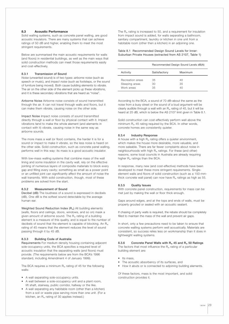
Table 8.1 Recommended Design Sound Levels for Inner-Suburban Private Houses (extracted from AS 2107, Table 1)
According to the BCA, a sound of 70 dB–about the same as thenoise from a busy street or the sound of a loud argument–will beclearly audible through a wall with an Rw rating of 45, but it will beheard at 25 dB, which is below the AS 2107 limit given in Table 8.1.
Solid construction can cost-effectively perform well above theminimum Rw 45 rating required by the BCA. In other words,concrete homes are consistently quieter.
8.3.4 Industry ResponseA house with a high Rw rating offers a quieter environment, which makes the house more desirable, more valuable, and more saleable. There are far fewer complaints about noise inneighbourhoods with high Rw ratings. For these (and other)reasons, some local councils in Australia are already requiringhigher Rw ratings than the BCA.
In response, many new (and cost-effective) methods have beendeveloped to meet these more stringent requirements. Single-element walls and floors of solid construction (such as a 150-mm-thick concrete wall panel) can now have Rw ratings as high as 55.
8.3.5 Quality IssuesWith concrete panel construction, requirements for mass can bemet just by making the wall or floor thick enough.
Gaps around edges, and at the tops and ends of walls, must beproperly grouted or sealed with an acoustic sealant.
If chasing of party walls is required, the rebate should be completelyfilled to maintain the mass of the wall and prevent air gaps.
In short, only a few precautions need to be taken to ensure thatconcrete walling systems perform well acoustically. Materials areconsistent, so success relies less on workmanship than it does inlightweight walling systems.
8.3.6 Concrete Panel Walls with Rw 45 and Rw 50 Ratings The factors that most influence the Rw rating of a particularbuilding element are:
• Its mass,• The acoustic absorbency of its surfaces, and• How it abuts or is connected to adjoining building elements.
Of these factors, mass is the most important, and solidconstruction provides it.
Recommended Design Sound Levels dB(A)
Activity Satisfactory Maximum
Recreation areas 35 40Sleeping areas 30 35Work areas 35 40
The BCA deems the following to have an Rw rating of 45:
• Solid precast concrete panel 100 mm thick without joints.• In-situ concrete 125 mm thick with a density not less that 2200
kg/m3, or 100 mm thick with a density not less that 2500 kg/m3.
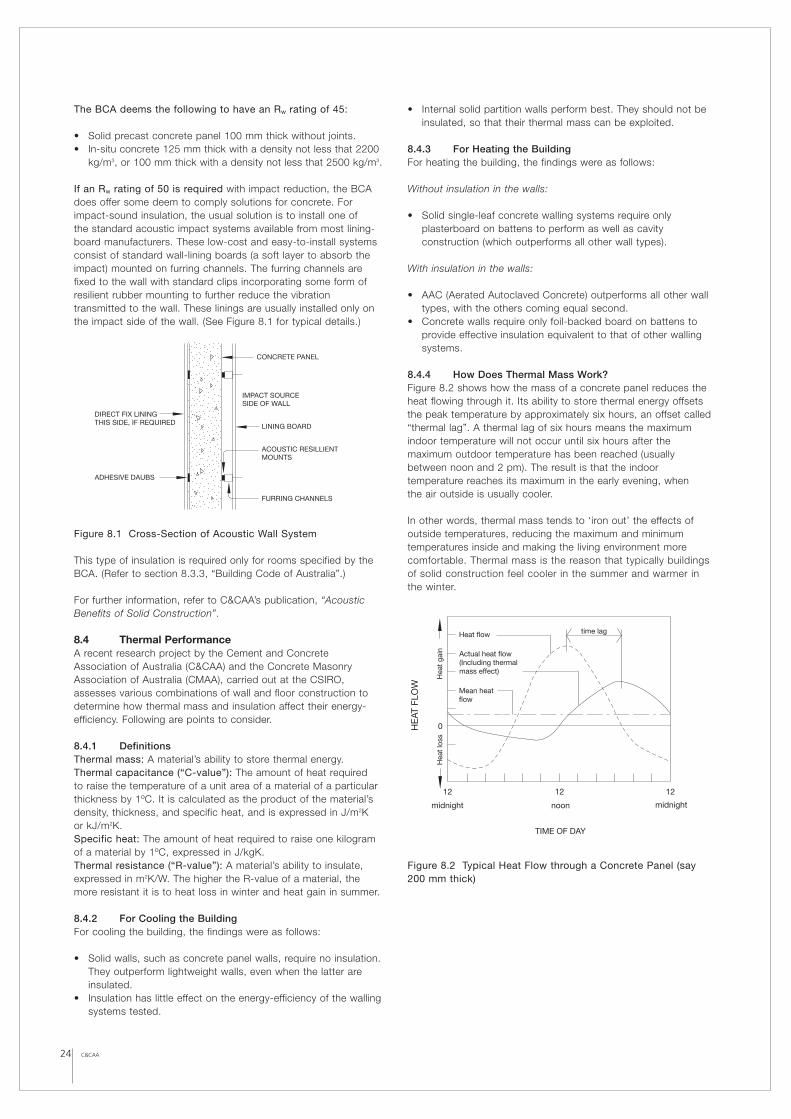
If an Rw rating of 50 is required with impact reduction, the BCAdoes offer some deem to comply solutions for concrete. Forimpact-sound insulation, the usual solution is to install one of the standard acoustic impact systems available from most lining-board manufacturers. These low-cost and easy-to-install systemsconsist of standard wall-lining boards (a soft layer to absorb theimpact) mounted on furring channels. The furring channels arefixed to the wall with standard clips incorporating some form ofresilient rubber mounting to further reduce the vibrationtransmitted to the wall. These linings are usually installed only onthe impact side of the wall. (See Figure 8.1 for typical details.)
Figure 8.1 Cross-Section of Acoustic Wall System
This type of insulation is required only for rooms specified by theBCA. (Refer to section 8.3.3, “Building Code of Australia”.)
For further information, refer to C&CAA’s publication, “AcousticBenefits of Solid Construction”.
8.4 Thermal PerformanceA recent research project by the Cement and ConcreteAssociation of Australia (C&CAA) and the Concrete MasonryAssociation of Australia (CMAA), carried out at the CSIRO,assesses various combinations of wall and floor construction todetermine how thermal mass and insulation affect their energy-efficiency. Following are points to consider.
8.4.1 DefinitionsThermal mass: A material’s ability to store thermal energy.Thermal capacitance (“C-value”): The amount of heat required to raise the temperature of a unit area of a material of a particularthickness by 1ºC. It is calculated as the product of the material’sdensity, thickness, and specific heat, and is expressed in J/m2K or kJ/m2K.Specific heat: The amount of heat required to raise one kilogramof a material by 1ºC, expressed in J/kgK.Thermal resistance (“R-value”): A material’s ability to insulate,expressed in m2K/W. The higher the R-value of a material, themore resistant it is to heat loss in winter and heat gain in summer.
8.4.2 For Cooling the BuildingFor cooling the building, the findings were as follows:
• Solid walls, such as concrete panel walls, require no insulation.They outperform lightweight walls, even when the latter areinsulated.
• Insulation has little effect on the energy-efficiency of the wallingsystems tested.
• Internal solid partition walls perform best. They should not beinsulated, so that their thermal mass can be exploited.
8.4.3 For Heating the Building For heating the building, the findings were as follows:
Without insulation in the walls:
• Solid single-leaf concrete walling systems require onlyplasterboard on battens to perform as well as cavityconstruction (which outperforms all other wall types).
With insulation in the walls:
• AAC (Aerated Autoclaved Concrete) outperforms all other walltypes, with the others coming equal second.
• Concrete walls require only foil-backed board on battens toprovide effective insulation equivalent to that of other wallingsystems.
8.4.4 How Does Thermal Mass Work?Figure 8.2 shows how the mass of a concrete panel reduces theheat flowing through it. Its ability to store thermal energy offsetsthe peak temperature by approximately six hours, an offset called“thermal lag”. A thermal lag of six hours means the maximumindoor temperature will not occur until six hours after themaximum outdoor temperature has been reached (usuallybetween noon and 2 pm). The result is that the indoortemperature reaches its maximum in the early evening, when the air outside is usually cooler.
In other words, thermal mass tends to ‘iron out’ the effects ofoutside temperatures, reducing the maximum and minimumtemperatures inside and making the living environment morecomfortable. Thermal mass is the reason that typically buildingsof solid construction feel cooler in the summer and warmer inthe winter.
Figure 8.2 Typical Heat Flow through a Concrete Panel (say200 mm thick)
24 C&CAA
CONCRETE PANEL
LINING BOARD
FURRING CHANNELS
ADHESIVE DAUBS
DIRECT FIX LININGTHIS SIDE, IF REQUIRED
ACOUSTIC RESILLIENTMOUNTS
IMPACT SOURCESIDE OF WALL
12 12 12
0
time lag
Mean heatflow
Actual heat flow(Including thermalmass effect)
Heat flow
HE
AT F
LOW
midnight noon
TIME OF DAY
midnight
Hea
t lo
ss
Hea
t ga
in
25C&CAA
8.4.5 R-value and C-valueDesigners use two main criteria when evaluating the thermalefficiency of building products: the R-value and (to a lesser extent)the thermal mass.
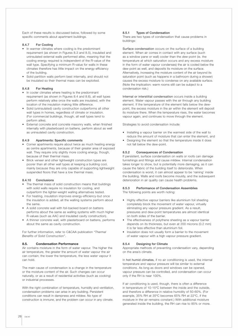
Table 8.2 lists R-values, as well as C-values (thermalcapacitances), for various building materials and thicknesses.
Table 8.2 R-Values and C-Values for Building Materials
As can be seen, high-density walling materials like concrete donot fare well when assessed purely on the basis of their R-values.But R-values do not take into account thermal mass; C-values do,and on the basis of C-values, concrete significantly outperformslighter-weight materials under cooling conditions.
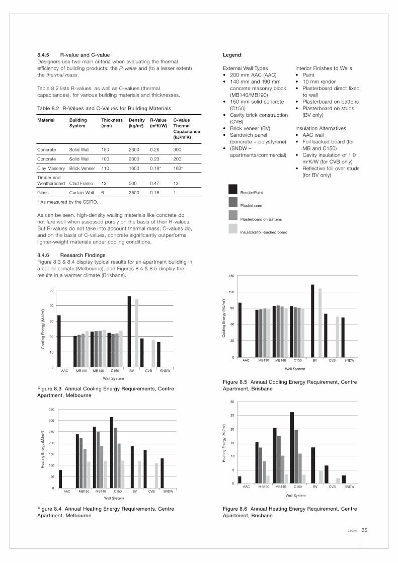
8.4.6 Research FindingsFigure 8.3 & 8.4 display typical results for an apartment building ina cooler climate (Melbourne), and Figures 8.4 & 8.5 display theresults in a warmer climate (Brisbane).
Material Building Thickness Density R-Value C-Value System (mm) (kg/m3) (m2K/W) Thermal
Capacitance(kJ/m2K)
Concrete Solid Wall 150 2300 0.26 300
Concrete Solid Wall 100 2300 0.23 200
Clay Masonry Brick Veneer 110 1600 0.18* 163*
Timber and Weatherboard Clad Frame 12 500 0.47 12
Glass Curtain Wall 6 2500 0.16 1
* As measured by the CSIRO.
AAC MB190 MB140 C150 BV CVB SNDW0
30
60
90
120
Coo
ling
Ene
rgy
(MJ/
m )2
150
Wall System
AAC MB190 MB140 C150 BV CVB SNDW
Wall System
Hea
ting
Ene
rgy
(MJ/
m )2
30
25
20
15
10
5
0
Figure 8.5 Annual Cooling Energy Requirement, CentreApartment, Brisbane
Figure 8.6 Annual Heating Energy Requirement, CentreApartment, Brisbane
0
10
20
AAC
30
40
50
MB190 MB140 C150 BV CVB SNDW
Wall System
Coo
ling
Ene
rgy
(MJ/
m )2
Figure 8.3 Annual Cooling Energy Requirements, CentreApartment, Melbourne
0AAC MB190 MB140 C150 BV CVB SNDW
50
100
150
200
250
300
350
Hea
ting
Ene
rgy
(MJ/
m )2
Wall System
Legend:
External Wall Types• 200 mm AAC (AAC)• 140 mm and 190 mm
concrete masonry block (MB140/MB190)
• 150 mm solid concrete(C150)
• Cavity brick construction(CVB)
• Brick veneer (BV)• Sandwich panel
(concrete + polystyrene)• (SNDW –
apartments/commercial)
Interior Finishes to Walls• Paint • 10 mm render• Plasterboard direct fixed
to wall• Plasterboard on battens• Plasterboard on studs
(BV only)
Insulation Alternatives• AAC wall• Foil backed board (for
MB and C150)• Cavity insulation of 1.0
m2K/W (for CVB only)• Reflective foil over studs
(for BV only)
Render/Paint
Plasterboard
Plasterboard on Battens
Insulated/foil-backed board
Figure 8.4 Annual Heating Energy Requirements, CentreApartment, Melbourne
Each of these results is discussed below, followed by somespecific comments about apartment buildings.
8.4.7 For Cooling• In warmer climates where cooling is the predominant
requirement (as shown in Figures 8.3 and 8.5), insulated anduninsulated external walls performed alike, meaning that thecooling energy required is independent of the R-value of thewall type. Specifying a minimum R-value for walls in theseclimates therefore has little impact on the energy-efficiency of the building.
• Solid partition walls perform best internally, and should not be insulated so their thermal mass can be exploited.
8.4.8 For Heating• In cooler climates where heating is the predominant
requirement (as shown in Figures 8.4 and 8.6), all wall typesperform relatively alike once the walls are insulated, with thelocation of the insulation making little difference.
• Solid (uninsulated) cavity construction outperforms all otherwall types in homes, regardless of climate or insulation. (For commercial buildings, though, all wall types tend toperform alike).
• External concrete and concrete masonry walls, when finishedinternally with plasterboard on battens, perform about as wellas uninsulated cavity construction.
8.4.9 Apartments: Specific comments• Corner apartments require about twice as much heating energy
as centre apartments, because of their greater area of exposedwall. They require only slightly more cooling energy, though,because of their thermal mass.
• Brick veneer and other lightweight construction types arepoorer than all other wall types at keeping a building cool,mainly because they are only capable of supporting lightweightsuspended floors that have a low thermal mass.
8.4.10 Conclusions• The thermal mass of solid construction means that buildings
with solid walls require no insulation for cooling, andoutperform the lighter-weight walling alternatives tested.
• For heating, insulation improves energy-efficiency-but oncethe insulation is added, all the walling systems perform aboutthe same.
• A solid concrete wall with foil-backed board on battensperforms about the same as walling systems with much higherR-values (such as AAC and insulated cavity construction).
• A thinner concrete wall, with plasterboard on battens, performsabout the same as cavity construction.
For further information, refer to C&CAA publication “ThermalBenefits of Solid Construction”.
8.5. Condensation PerformanceAir contains moisture in the form of water vapour. The higher theair temperature, the greater the amount of water vapour the aircan contain; the lower the temperature, the less water vapour itcan hold.
The main cause of condensation is a change in the temperatureor the moisture content of the air. Such changes can occurnaturally, or as a result of residential activities (such as cooking) or industrial processes.
With the right combination of temperature, humidity and ventilation,condensation problems can arise in any building. Persistentconditions can result in dampness and mildew. No type ofconstruction is immune, and the problem can occur in any climate.
8.5.1 Types of CondensationThere are two types of condensation that cause problems inbuildings:
Surface condensation occurs on the surface of a buildingelement. When air comes in contact with any surface (such as a window pane or wall) cooler than the dew-point (ie. thetemperature at which saturation occurs and any excess moisturein the form of water vapour condenses) the air is cooled below thedew-point as well, and deposits its moisture on the surface.Alternatively, increasing the moisture content of the air beyond itssaturation point (such as happens in a bathroom during a shower)causes the excess moisture to condense on any available surface.(Note the implication: warm rooms still can be subject to acondensation risk.)
Internal or interstitial condensation occurs inside a buildingelement. Water vapour passes with the air through any buildingelement. If the temperature of the element falls below the dew-point, the excess moisture in the air within the element will depositits moisture there. When the temperature rises, the water becomesvapour again, and continues to move through the element.
Strategies to avoid condensation include:
• Installing a vapour barrier on the warmest side of the wall toreduce the amount of moisture that can enter the element, and
• Designing the element so that the temperature inside it doesnot fall below the dew-point.
8.5.2 Consequences of CondensationIf persistent, surface condensation on walls or roofs can damagefurnishings and fittings and cause mildew. Internal condensationtakes longer to show, but is potentially more damaging, as it cancause the fabric of the building itself to deteriorate. Whencondensation is worst, it can almost appear to be ‘raining’ insidethe building. Walls and roofs become mouldy, and the subsequentdeterioration in air quality can cause health problems.
8.5.3 Performance of Condensation AssembliesThe following points are worth noting:
• Highly effective vapour barriers like aluminium foil sheetingcompletely block the movement of water vapour, virtuallyeliminating any vapour pressure gradient. As a result,pressures and dew-point temperatures are almost identical on both sides of the barrier.
• The effectiveness of polythene sheeting as a vapour barrierdepends on its thickness, but even at 200 microns (0.2 mm) it is far less effective than aluminium foil.
• Insulation does not usually form a barrier to the movement of water vapour with a high vapour pressure gradient.
8.5.4 Designing for Climate Appropriate methods of preventing condensation vary, dependingon the area’s climate.
In hot humid climates, if no air conditioning is used, the internaltemperature and vapour pressure will be similar to externalconditions. As long as doors and windows can be opened, vapour pressure can be controlled, and condensation can occuronly if the RH is near 100%.
If air conditioning is used, though, there is often a difference in temperature of 10-15ºC between the inside and the outside,and therefore a difference in relative humidity of 50-60%. (Forexample, 35% RH at 35ºC becomes 65% RH at 22ºC, if themoisture in the air remains constant.) With additional moisturegenerated inside the building, the RH can rise to 85% or more.
26 C&CAA
Fortunately, the dehumidifying effect of air conditioning units willreduce this considerably. Condensation within the walls is unlikelyunless the internal temperature falls or the RH increases, therebyraising the dew-point temperature.
For houses in hot humid climates, you should:
• Install a vapour barrier on the warm (exterior) side of the wall toreduce interstitial condensation as the RH approaches 100%.
• Avoid “thermal bridges” (connections between cool surfacesand the exterior), which cause condensation on the outside of the wall.
• Avoid over-cooling the interior, which can bring the internaltemperature below the dew-point and cause surface orinterstitial condensation.
• Avoid low-permeability wall coverings or coatings on theinterior, as moisture can accumulate behind the covering or coating.
In cool climates, the difference in temperature between the insideand outside can be as high as 20-25ºC, leading to an internal RH as much as 40-50% lower than the outside one. With solidconstruction, the temperature of the concrete elements can fallbelow the dew-point, especially if insulation is used on the internalsurfaces (as it prevents the panels from being heated from theinside). The risk increases as the relative humidity of the outsideair increases.
For houses in cool climates, you should:
• Reduce the amount of moisture generated in the building tominimise the vapour pressure and dew-point.
• Install a vapour barrier on the warm side of the wall to preventwater vapour from reaching the cool surfaces. With a vapourbarrier installed, no condensation will occur as long as thetemperature at the barrier remains above the dew-point.
• Use external insulation to heat the wall elements moreefficiently. Maintaining the temperature of the wall above thedew-point prevents condensation, however the building isoften not heated sufficiently.
• Use natural and/or mechanical ventilation to expel moisture or water vapour.
• If you cannot remove the risk of severe condensation, makesure cavities are drained to prevent damage to the finishes.
8.5.5. Designing to Avoid Condensation The easiest way to avoid condensation is simply to prevent moistair from coming into contact with cold surfaces. Doing this maymean controlling a number of factors that can causecondensation. As designers have little control over the use of the building, it’s wise to include a few backup strategies forminimising condensation in case it occurs.
These are the main strategies for minimising condensation, inorder of importance:
1. Provide good ventilation to reduce or control the RH andinternal vapour pressures (and thereby the dew-pointtemperature gradients).
2. Provide enough heating to increase the temperature of thesolid wall. (This can be difficult in buildings that are not alwaysoccupied, or that are heated for only short periods in theevenings.) Heating should be throughout the building, not justin the living areas.
3. Install insulation (in conjunction with heating) to prevent heatloss through the walls and floor.
4. Reduce the amount of moisture generated in the building, orremove it at the source, to help control the RH and vapourpressure.
5. Prevent moisture from moving to colder areas of the building.6. Avoid thermal bridges.7. Install vapour barriers on internal walls in cold climates, so that
condensation will occur only if the temperature of the wall fallsbelow the internal dew-point.
8. Coat the outside surface with a permeable layer to allow waterto evaporate rather than accumulate in the wall.
8.5.6 Types of Vapour Barriers Vapour barriers come in many forms, depending on where they’reto be used. The following types are available:
• Polyethylene sheets• Reflective foil membranes (such as aluminium foil)• Foil-backed plasterboards• Impermeable rigid insulation• Part membranes with low permeability• Specialised external coatings
8.5.7 Ventilation The function of ventilation in buildings is to:
• Improve indoor air quality.• Reduce indoor moisture content.• Keep the indoor climate comfortable.• Cool the building structure.
Internally-generated humidity can reduce air quality and lead tocondensation. Ventilation can help address this problem, but iseffective only if external conditions are better than interior ones. If ventilation is to reduce humidity in a room, the level of humiditymust be higher inside than outside.
The types of ventilation that can be used are as follows:
Trickle Ventilation: Permanent ventilation can be provided forspaces with consistently high humidity to keep air moving throughand to discourage hot humid air from remaining in the space.Fixed grilles in bathroom windows are a good example of thistechnique.
Cross-ventilation: Openings in a façade can be linked to increasethe airflow through the space and move hot humid air out of thebuilding. The ventilation rate should be such that the entirevolume of air is replaced 0.5 to 1.5 times per hour.
Cavity Ventilation: Ventilators can be planted in wall surfaces toenable air movement in cavities. This technique can removehigh levels of humidity in cavities.
Mechanical Ventilation: Fan-assisted ventilation can be used toexpel hot humid air by:
• Bringing in external air to replace the moist air, or• Expelling the moist air by extraction.
The first option (intake fans) is appropriate if external air is neededto cool the interior, or if a great deal of moisture is beinggenerated by processes inside the building.
The second option (exhaust fans) is best for small areas withlocalised moisture problems, such as bathrooms and kitchens.The fans can be connected to hygrometers and thermostats toreduce the risk of condensation. Always run the humid exhaust tothe outside, not into an interior cavity or space (especially exhaustfrom clothes driers). You will also need to ensure that anequivalent amount of air can enter the building somewhere, toreplace what’s expelled.
27C&CAA
C&CAA28
8.5.8 SummaryCondensation in solid construction can be avoided byunderstanding the processes that cause it, and designing a strategy to cater for the causes. The solution may be acomposite one, involving a combination (for instance) ofinsulation, vapour barriers and dry lining. The positioning ofvapour barriers is particularly important, as the proper locationsfor them depends on the area’s climate and on the type ofenvironmental control used in the building.
8.6 Fire Resistance PerformanceAll solid concrete panel walling systems have high fire resistancelevels (FRL)–that is, they can withstand the effects of fire andremain structurally sound for a relatively long period of time.
The Building Code of Australia (BCA) sets out the required FRL for various building elements. This requirement depends on thetype of construction, the purpose of the building, the height instoreys, and proximity to the fire source.
8.6.1 For Residential BuildingsFor both Class 1a and 10a residential buildings, the fire resistanceperformance of the walls will determine its ability to provide fireseparation of the fire source from:
• the external surrounding of the building containing the firesource.
• the building containing the fire source from the adjoining orneighbouring buildings.
The FRL gives the Fire-Resistance Periods (FRP) for structuraladequacy, integrity, and insulation, respectively in minutes. Solidconcrete panel walling can easily be designed to achieve FRLrequirements, because concrete is a naturally good fire barrier.
Section 5 - Design for Fire Resistance of AS 3600 – ConcreteStructures provides methods for determining the various FRPs forconcrete walls. Concrete panel systems must comply with theserequirements. To achieve the required FRPs, certain criteria mustbe met, as defined in AS 3600:
• Structural insulation: Effective concrete wall thickness of80mm will achieve 60 minutes and a solid 150 mm thick panel will achieve 180 minutes.
• Structural integrity: Must comply to the same level ofFRP as structural insulation.
• Structural adequacy: Must comply to the same level of FRP as structural insulation, as long as AS3600, clause 5.7.4 is satisfied.
The joints between the panels must also satisfy the appropriateFRPs. Sealant manufacturers can provide data on theperformance of proprietary sealants. This topic is discussed inmore depth in the section on Chapter 7, “Panel Jointing”.).
8.7 Termite ResistanceStandard concrete with a minimum strength of 20 MPa isregarded as termite resistant-that is, termites cannot “eat” theirway through it-so termites are certainly less likely to attackconcrete panel homes than they are brick veneer or standardtimber-framed homes (which is one of the advantages of concretepanel walling). But termites can still enter through openings in thewalls or floor (such as cracks and joints).
Termites live in most areas of Australia, so the risk of infestationmust be assessed and managed. The BCA and AustralianStandard AS 3660.1 require that a termite risk assessment beperformed and (if required) a management system be employed. The intention of a termite management system is to ensure that
termites will not enter a dwelling by a concealed route. Termitebarriers will not stop termite activity from occurring on site.
This section discusses those requirements, and how they apply to concrete panel walling (and floor slab edges).
8.7.1 The BCAAccording to the BCA, installing a termite risk managementsystem* means doing both of the following:
• Installing a termite barrier or combination of barrier systems in accordance with AS 3660.1. (Refer to the more detailedinformation below on concrete slabs-on-ground andsuspended slabs) or termite resistant materials.
• Providing a durable notice, permanently fixed to the dwelling in a prominent location (such as the meter box), that states: – The method of protection,– The date the system was installed,– The life expectancy of the chemical barrier (if one is used),
as displayed on a National Registration Authority label, and– The installer’s or manufacturer’s recommendations as to the
scope and frequency of future inspections for termite activity.
* Variations and additional measures may be required for buildingin Queensland and/or the Northern Territory. Refer to the BCA,Part 3.1.3 for detailed information.
Concrete Slab-on-Ground A concrete slab-on-ground is therecommended ground floor system for a concrete panel home.The slab can support the wall panels on a rebated edge, or elsethe slab edge can be supported from the backs of the wallpanels. If the former is true, then the slab can be used as part ofa termite barrier system – but only if all the following are compliedwith as well:
• The slab must be designed and constructed to comply with AS 2870, and– For monolithic slabs, the penetrations and perimeter must
be protected in accordance with the BCA requirements.– For non-monolithic slabs, the penetrations, control joints
and perimeter must be protected in accordance with theBCA requirements.
• For slabs not constructed in accordance with AS 2870, theentire area beneath the slab and the perimeter must beprotected in accordance with the BCA requirements.
• If the edge of a slab-on-ground is used as a perimeter barrier,then:– The edge of slab must be left exposed, and must be a
minimum of 75 mm inspection zone (either on the horizontalor vertical face of a slab edge).
– The face of the exposed edge must not be rough,honeycombed, or rippled, or contain any otherimperfections that could conceal termite activity.
– It is not permitted to fix tiles to the exposed surface, or torender it.
Termite barrier systems are designed so that if termites arepresent, they will be forced into visible areas where they can beseen during regular inspections. Inspection areas such as exposededges of slabs-on-ground should always be kept clean and free ofdebris. Attachments such as downpipes should be located so asto permit visual inspection. A clearance of not less than 40 mmbetween fittings and the edge of the slab is usually adequate.
Cracking in concrete slabs constructed to AS 2870 is common,but the widths of the cracks are controlled by adequate steelreinforcement in the concrete. The appearance of cracks does notnecessarily indicate a failure of the termite barrier system; manycracks do not penetrate the full thickness of the slab depth, whilethose that do are rarely wide enough for termites.
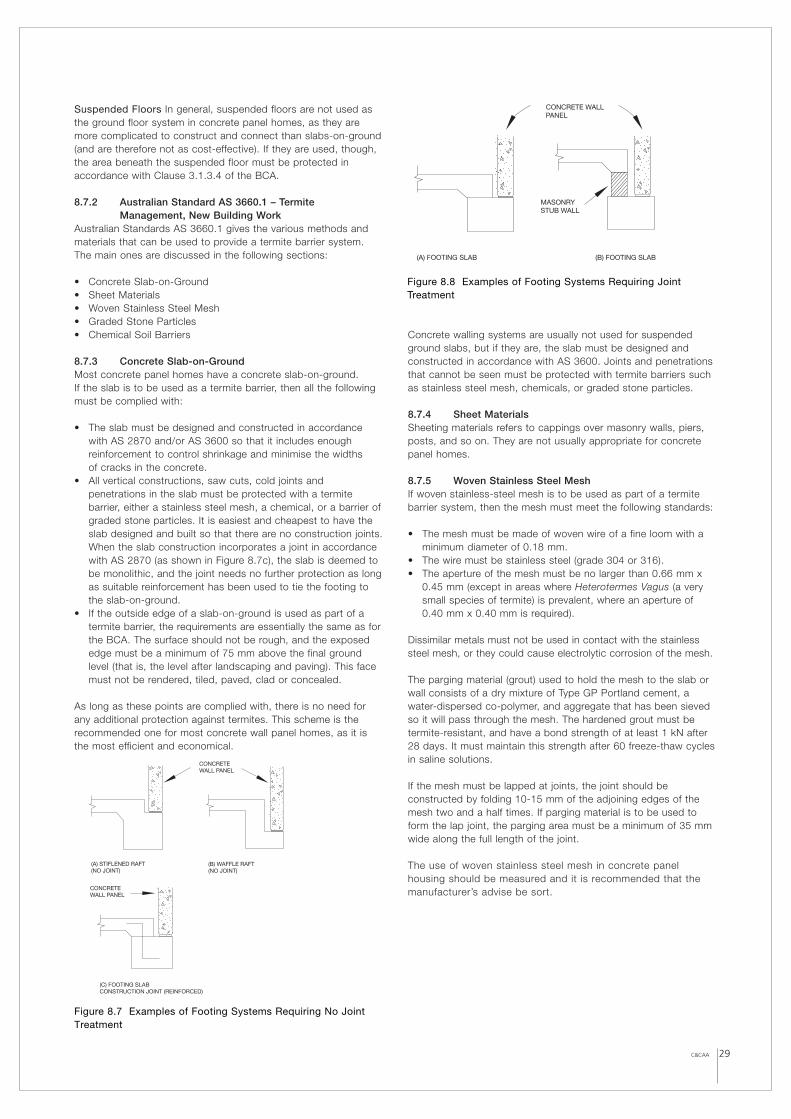
C&CAA 29
Suspended Floors In general, suspended floors are not used asthe ground floor system in concrete panel homes, as they aremore complicated to construct and connect than slabs-on-ground(and are therefore not as cost-effective). If they are used, though,the area beneath the suspended floor must be protected inaccordance with Clause 3.1.3.4 of the BCA.
8.7.2 Australian Standard AS 3660.1 – TermiteManagement, New Building Work
Australian Standards AS 3660.1 gives the various methods andmaterials that can be used to provide a termite barrier system.The main ones are discussed in the following sections:
• Concrete Slab-on-Ground• Sheet Materials• Woven Stainless Steel Mesh• Graded Stone Particles• Chemical Soil Barriers
8.7.3 Concrete Slab-on-Ground Most concrete panel homes have a concrete slab-on-ground. If the slab is to be used as a termite barrier, then all the followingmust be complied with:
• The slab must be designed and constructed in accordancewith AS 2870 and/or AS 3600 so that it includes enoughreinforcement to control shrinkage and minimise the widths of cracks in the concrete.
• All vertical constructions, saw cuts, cold joints andpenetrations in the slab must be protected with a termitebarrier, either a stainless steel mesh, a chemical, or a barrier ofgraded stone particles. It is easiest and cheapest to have theslab designed and built so that there are no construction joints.When the slab construction incorporates a joint in accordancewith AS 2870 (as shown in Figure 8.7c), the slab is deemed tobe monolithic, and the joint needs no further protection as longas suitable reinforcement has been used to tie the footing tothe slab-on-ground.
• If the outside edge of a slab-on-ground is used as part of atermite barrier, the requirements are essentially the same as forthe BCA. The surface should not be rough, and the exposededge must be a minimum of 75 mm above the final groundlevel (that is, the level after landscaping and paving). This facemust not be rendered, tiled, paved, clad or concealed.
As long as these points are complied with, there is no need forany additional protection against termites. This scheme is therecommended one for most concrete wall panel homes, as it isthe most efficient and economical.
Concrete walling systems are usually not used for suspendedground slabs, but if they are, the slab must be designed andconstructed in accordance with AS 3600. Joints and penetrationsthat cannot be seen must be protected with termite barriers suchas stainless steel mesh, chemicals, or graded stone particles.
8.7.4 Sheet Materials Sheeting materials refers to cappings over masonry walls, piers,posts, and so on. They are not usually appropriate for concretepanel homes.
8.7.5 Woven Stainless Steel Mesh If woven stainless-steel mesh is to be used as part of a termitebarrier system, then the mesh must meet the following standards:
• The mesh must be made of woven wire of a fine loom with aminimum diameter of 0.18 mm.
• The wire must be stainless steel (grade 304 or 316).• The aperture of the mesh must be no larger than 0.66 mm x
0.45 mm (except in areas where Heterotermes Vagus (a verysmall species of termite) is prevalent, where an aperture of0.40 mm x 0.40 mm is required).
Dissimilar metals must not be used in contact with the stainlesssteel mesh, or they could cause electrolytic corrosion of the mesh.
The parging material (grout) used to hold the mesh to the slab orwall consists of a dry mixture of Type GP Portland cement, awater-dispersed co-polymer, and aggregate that has been sievedso it will pass through the mesh. The hardened grout must betermite-resistant, and have a bond strength of at least 1 kN after28 days. It must maintain this strength after 60 freeze-thaw cyclesin saline solutions.
If the mesh must be lapped at joints, the joint should beconstructed by folding 10-15 mm of the adjoining edges of themesh two and a half times. If parging material is to be used toform the lap joint, the parging area must be a minimum of 35 mmwide along the full length of the joint.
The use of woven stainless steel mesh in concrete panelhousing should be measured and it is recommended that themanufacturer’s advise be sort.
Figure 8.7 Examples of Footing Systems Requiring No JointTreatment
(C) FOOTING SLABCONSTRUCTION JOINT (REINFORCED)
CONCRETE WALL PANEL
(B) FOOTING SLAB(A) FOOTING SLAB
CONCRETE WALL PANEL
MASONRYSTUB WALL
Figure 8.8 Examples of Footing Systems Requiring JointTreatment
(B) WAFFLE RAFT(NO JOINT)
(A) STIFLENED RAFT(NO JOINT)
CONCRETE WALL PANEL
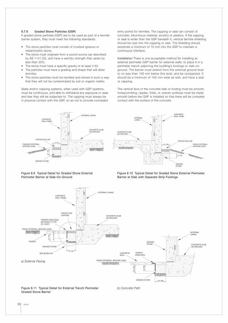
30 C&CAA
8.7.6 Graded Stone Particles (GSP)If graded stone particles (GSP) are to be used as part of a termitebarrier system, they must meet the following standards:
• The stone particles must consist of crushed igneous ormetamorphic stone.
• The stone must originate from a sound source (as describedby AS 1141.22), and have a wet/dry strength that varies byless than 35%.
• The stone must have a specific gravity of at least 2.52.• The particles must have a grading and shape that will deter
termites.• The stone particles must be handled and stored in such a way
that they will not be contaminated by soil or organic matter.
Seals and/or capping systems, when used with GSP systems,must be continuous, and able to withstand any exposure or wearand tear they will be subjected to. The capping must always be in physical contact with the GSP, so as not to provide concealed
entry points for termites. The capping or seal can consist ofconcrete, bituminous material, acrylics or plastics. If the cappingor seal is wider than the GSP beneath it, vertical termite shieldingshould be cast into the capping or seal. The shielding shouldpenetrate a minimum of 75 mm into the GSP to maintain acontinuous interface.
Installation There is one acceptable method for installing anexternal perimeter GSP barrier for external walls: to place it in aperimeter trench adjoining the building’s footings or slab-on-ground. The barrier must extend from the external ground levelto no less than 100 mm below this level, and be compacted. Itshould be a minimum of 100 mm wide as well, and have a sealor capping.
The vertical face of the concrete slab or footing must be smooth;honeycombing, ripples, folds, or uneven surfaces must be madesmooth before the GSP is installed so that there will be completecontact with the surface of the concrete.
CONCRETE WALL PANEL
PROTECTIVE CAP
100 MIN
100
MIN
INTERNAL LINING
FINISHED EXTERNALGROUND LEVEL
GRADED STONE
CONCRETE SLAB ON GROUND
INTERNAL LINING
CONCRETE WALL PANEL
CONCRETE SLAB ON GROUND
FINISH EXTERNAL GROUND LEVEL
100 MIN
100 MIN
GRADED STONE
PROTECTIVE CAP
GRADED STONE
CONCRETE PATH
FINISH EXTERNAL GROUND LEVEL
INTERNAL LINING
100 MIN
100
MIN
75 M
IN
TERMITE SHIELDING
GRADED STONE
CONCRETE SLABON GROUND
INTERNAL LINING
CONCRETE WALL PANEL
PROTECTIVE CAPPING
TERMITE SHIELDING(EXTENDS TO TOP OF JOINT)
PAVERS
FINISH EXTERNAL GROUND LEVEL
75 M
IN
100
MIN
100 MIN
GRADED STONE
SEE (B) BELOW
CONCRETE SLAB ON GROUND
Figure 8.9 Typical Detail for Graded Stone ExternalPerimeter Barrier at Slab-On-Ground
Figure 8.10 Typical Detail for Graded Stone External PerimeterBarrier at Slab with Separate Strip Footings
Figure 8.11 Typical Detail for External Trench PerimeterGraded Stone Barrier
a) External Paving
b) Concrete Path
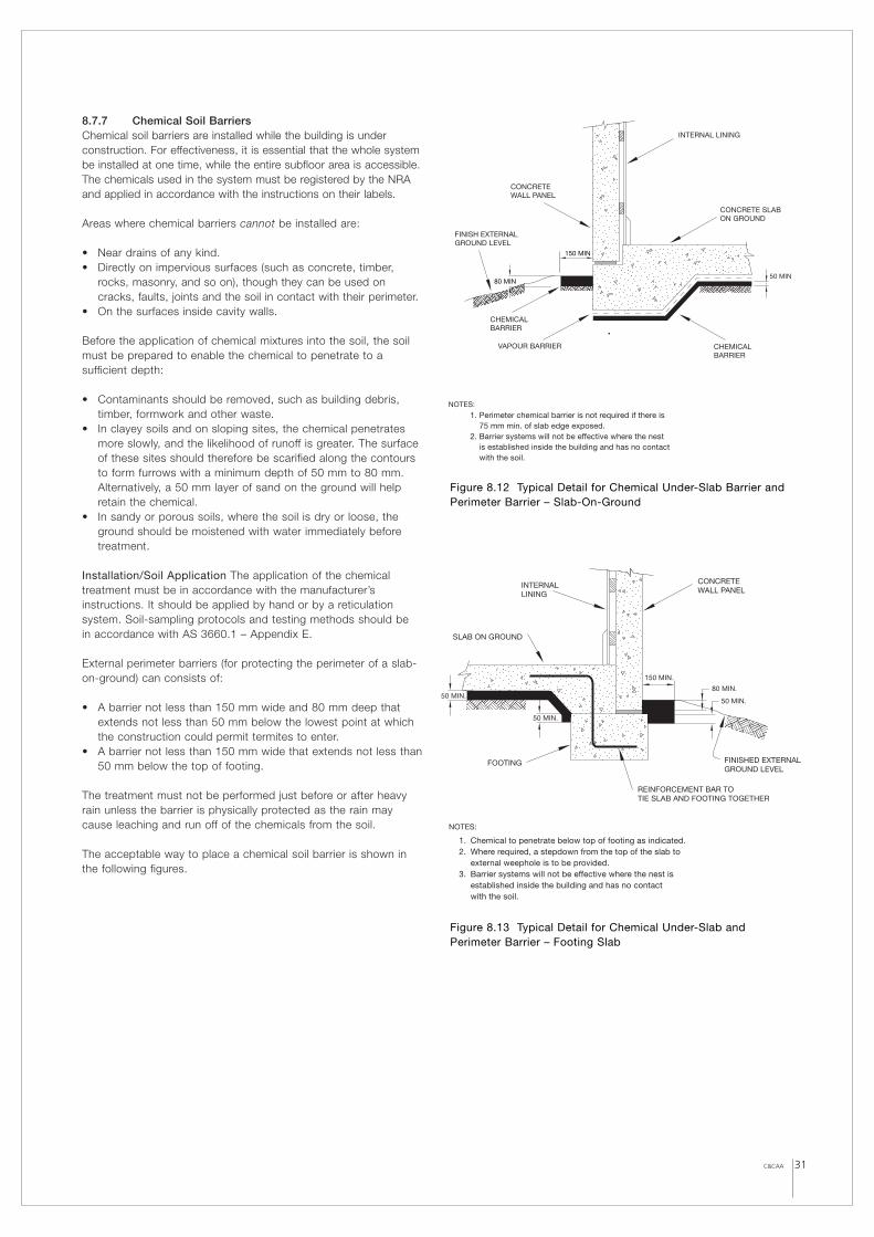
C&CAA 31
8.7.7 Chemical Soil BarriersChemical soil barriers are installed while the building is underconstruction. For effectiveness, it is essential that the whole systembe installed at one time, while the entire subfloor area is accessible.The chemicals used in the system must be registered by the NRAand applied in accordance with the instructions on their labels.
Areas where chemical barriers cannot be installed are:
• Near drains of any kind.• Directly on impervious surfaces (such as concrete, timber,
rocks, masonry, and so on), though they can be used oncracks, faults, joints and the soil in contact with their perimeter.
• On the surfaces inside cavity walls.
Before the application of chemical mixtures into the soil, the soilmust be prepared to enable the chemical to penetrate to asufficient depth:
• Contaminants should be removed, such as building debris,timber, formwork and other waste.
• In clayey soils and on sloping sites, the chemical penetratesmore slowly, and the likelihood of runoff is greater. The surfaceof these sites should therefore be scarified along the contoursto form furrows with a minimum depth of 50 mm to 80 mm.Alternatively, a 50 mm layer of sand on the ground will helpretain the chemical.
• In sandy or porous soils, where the soil is dry or loose, theground should be moistened with water immediately beforetreatment.
Installation/Soil Application The application of the chemicaltreatment must be in accordance with the manufacturer’sinstructions. It should be applied by hand or by a reticulationsystem. Soil-sampling protocols and testing methods should be in accordance with AS 3660.1 – Appendix E.
External perimeter barriers (for protecting the perimeter of a slab-on-ground) can consists of:
• A barrier not less than 150 mm wide and 80 mm deep thatextends not less than 50 mm below the lowest point at whichthe construction could permit termites to enter.
• A barrier not less than 150 mm wide that extends not less than50 mm below the top of footing.
The treatment must not be performed just before or after heavyrain unless the barrier is physically protected as the rain maycause leaching and run off of the chemicals from the soil.
The acceptable way to place a chemical soil barrier is shown inthe following figures.
NOTES:
1. Chemical to penetrate below top of footing as indicated.2. Where required, a stepdown from the top of the slab to
external weephole is to be provided.3. Barrier systems will not be effective where the nest is
established inside the building and has no contactwith the soil.
50 MIN.
50 MIN.
50 MIN.
150 MIN.
80 MIN.
CONCRETE WALL PANEL
INTERNAL LINING
SLAB ON GROUND
FINISHED EXTERNALGROUND LEVEL
FOOTING
REINFORCEMENT BAR TOTIE SLAB AND FOOTING TOGETHER
Figure 8.13 Typical Detail for Chemical Under-Slab andPerimeter Barrier – Footing Slab
50 MIN
150 MIN
80 MIN
NOTES:
1. Perimeter chemical barrier is not required if there is 75 mm min. of slab edge exposed. 2. Barrier systems will not be effective where the nest is established inside the building and has no contact with the soil.
INTERNAL LINING
CONCRETE SLAB ON GROUND
FINISH EXTERNAL GROUND LEVEL
VAPOUR BARRIER
CHEMICAL BARRIER
CONCRETE WALL PANEL
CHEMICAL BARRIER
Figure 8.12 Typical Detail for Chemical Under-Slab Barrier andPerimeter Barrier – Slab-On-Ground
8.7.8 Conclusion To provide an efficient and cost-effective termite barrier system fora concrete wall panel home:
• Design and construct the slab-on-ground in accordance withAS 2780 or AS 3600. The perimeter slab edges should befinished smooth, and should sit at least 75 mm above the finalground level.
• Concrete wall panels should bear onto a rebate of (say) 40 mmon the top edge of the slab, so that no part of the concretewall panels is below the 75 mm inspection zone formed by thevertical face of the concrete slab-on-ground perimeter edge.
• Minimise the number of joints and penetrations in the slab, asthese will be the only areas that will require additionalprotection (such as woven stainless steel mesh, a chemicalbarrier, or graded stone particles).
The combination of the three points will provide a suitable termitebarrier scheme for a concrete panel home. However, the abovescenario is for a simple case and only one of many possiblesolutions. Each individual housing situation must be examinedthoroughly to derive the best solution to suit each case.
8.8 WeatherproofingConcrete panel homes are usually more weather-tight than mostother types of homes simply because of the building materials andthe construction method. Concrete panels are denser (andtherefore more impermeable) than conventional masonry, timberand cladding. The concrete used to produce wall panels has acompressive strength of 32 to 40 MPa. The solid construction of aconcrete panel home means there are fewer entry points for waterand wind ingress.
The issue of weather-tightness should not be taken lightly, though.Making a concrete panel home suitably weather-tight still requiresgood planning, design and construction methods.
Water can penetrate through concrete wall panels in two ways:
• Through the concrete itself (though this is rare), or • Through the joints between panels and other panels, the
footings, or the roof.
8.8.1 Water Permeability in ConcreteThe watertightness of concrete is its level of impermeability towater under ambient (normal) pressure. (The term “waterproof”cannot strictly be applied to concrete, as it is a porous material andcan therefore be penetrated by water under high enough pressure.)
To increase the watertightness of concrete:
• Keep the water-to-cement ratio as low as reasonably possible,while maintaining satisfactory workability, good compactionand adequate hydration. Blended cements can help make theconcrete more impermeable. Silica fume can reduce the size of the pores in the cement paste.
• Use chemical admixtures, such as: – Water-reducing admixtures to increase the workability of
concrete and reduce the water-cement ratio.– Superplasticisers (high-range water reducers) to allow a
more flowable concrete with a low water-cement ratio andto promote efficient compaction of the concrete.
– Air-entraining agents to increase the durability of concretewhere freeze thaw environments are encountered.
– Permeability-reducing admixtures (waterproofing agents)that minimise moisture uptake by the concrete surfaceunder normal environmental conditions.
• Add acrylic copolymer latex to a suitable concrete mix toproduce a polymer-modified concrete that is highly resistant to penetration by water and chloride ions.
Crack Control One of the easiest ways for water to penetrate aconcrete wall is through cracks that have formed in the panel.Cracking can occur because of a variety of reasons:
• Flexural cracks are caused by excessive loads. (Widths of upto 0.3 – 0.4 mm may be acceptable in dry areas that areprotected from the weather.)
• Plastic shrinkage cracking is caused by the surface drying toorapidly during the first two to four hours after mixing. This typeof cracking can often occur through the full thickness of thepanel, allowing water to penetrate. Strong winds, hightemperatures and low humidity are likely to cause this kind ofcracking. To minimise plastic shrinkage cracking, protect thesurface of the concrete by spraying it with a layer of aliphaticalcohol after the final screeding, by applying a curingmembrane or sheeting after the concrete sets, or by wettingthe formwork.
• Shrinkage cracking is caused by drying and by temperaturechanges that cause the concrete to contract, and can extendthrough the thickness of the wall panel. As the wall panelsystems discussed in this handbook are cast flat similar to aconcrete floor slab and then erected into vertical position,minimum reinforcement requirement for crack control must be addressed. AS 3600 provides such minimum requirementsto satisfy this.
Surface Treatments It is also possible to treat the surface of aconcrete panel with a sealant or to cover it with a membrane toimprove its watertightness. Mainly, though, these treatments areused on below-ground concrete panels (such as those inbasements). Most concrete panel homes will not need a surfacetreatment any more complicated than a coat of paint or render, as concrete panels are already sufficiently watertight under normalenvironmental conditions.
• Waterproofing membranes. Available types of membranesinclude:– Cement-based render (with or without chemical admixtures
to make the concrete more water-repellent)– Resin-based render (for resistance to chemicals)– Continuous vapour-proof membranes (such as in-situ
membranes of rubber, asphalt or plastic, or liquidmembranes applied by roller-coating)
• Concrete impregnation sealants can be used to make concretewatertight. These include: – Silicates (usually sodium silicate) reacts with the calcium
ions in the concrete to form a calcium-silicate gel. Thematerial is sprayed or brushed into the surface of theconcrete, and penetrates dense, well hydrated concrete toa depth of 5mm. The reaction hardens the surface, but indry conditions the gel can eventually dry out completely,allowing water to enter through the spaces it occupied.There are products available for inhibiting the dehydration of silicates in dry conditions.
– Silanes and siloxanes are low-viscosity liquid sealants thatare applied to the surface of the finished concrete. Theycreate a barrier to moisture by covering the pore surfaceswith hydrocarbon chains that repel water.
– Crystalline sealers block water by causing crystals to growinside the pores and seal them. Temperature fluctuationsafter application of the sealer can cause uneven crystalgrowth, so these sealers are best suited to interior orbelow-ground applications where the temperature willremain fairly constant.
32 C&CAA
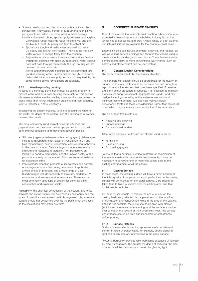
• Surface coatings protect the concrete with a relatively thicksurface film. They usually consist of a polymer binder, as wellas pigments and fillers. Polymers used in these coatingsinclude chlorinated rubber, epoxies, polyurethanes and acrylics. – Chlorinated rubber coatings resist moisture well and are
flexible, but resist UV poorly and tend to collect dirt.– Epoxies are tough and resist water very well, but resist
UV poorly and are not very flexible. They also do not allowwater vapour to escape freely from the concrete.
– Polyurethane paints can be formulated to produce flexiblewaterproof coatings with good UV resistance. Water vapourdoes not pass through them easily, though, so they cannotbe used on damp concrete.
– Acrylic and methacrylate coatings can be pigmented, aregood at resisting water, carbon dioxide and UV, and do notcollect dirt. Most of these polymers are not very flexible, butsome flexible acrylic formulations are available.
8.8.2 Weatherproofing JointingAll joints in a concrete panel home must be sealed properly toprevent water and wind from entering the structure. This sectiondiscusses available weatherproofing materials that can be used inthese joints. (For further information on joints and their detailing,refer to Chapter 7, “Panel Jointing”.)
In selecting the sealant material, take into account the width ofthe joints, the depth of the sealant, and the anticipated movementbetween the panels.
The most commonly-used sealant types are silicones andpolyurethanes, as they have the best properties for coping withboth external conditions and movement between panels.
• Silicones (organopolysiloxane with a curing agent). Advantagesinclude a transparent finish, excellent resistance to UV andhigh temperatures, ease of application, and excellent adhesionto the parent material. Disadvantages include a low tensilestrength and resistance to abrasion, non-paintability, aninability to bond to themselves, and the uneven quality of theproducts currently on the market. Silicones are most suitablefor expansion joints.
• Polyurethanes (reaction products of isocyanates and polyols).Advantages include a fast curing time, ease of application, a wide choice of products, and a wide range of uses.Disadvantages include sensitivity to moisture, moderate UVresistance, and low temperature resistance. These are themost commonly-used type of sealant for concrete panelconstruction and expansion joints.
Paintability The chemical composition of the sealant, and of itssolvents and curing agents, will determine its paintability and thetypes of paint that can be used on it. As a general rule, an elasticsealant should not be painted over, as the paint is not as elasticas the sealant and may crack over time.
9 CONCRETE SURFACE FINISHES
One of the reasons that concrete wall panelling is becoming moreaccepted across all sectors of the building industry is that it nolonger has to appear flat and grey. A wide variety of both externaland internal finishes are available for the concrete panel home.
External finishes can include chamfers, grooving, and rebates, aswell as various surface coatings and textures that can be used tocreate an individual design for each home. These finishes can becontinued internally, or more conventional wall finishes (such asbattens and plasterboard) can be used instead.
9.1 General Design Considerations Simplicity of finish should be the primary objective.
The concrete mix design should be appropriate for the quality ofsurface finish required. It should be cohesive and rich enough toreproduce any fine textures that have been specified. To ensure a uniform colour on concrete surfaces, it is necessary to maintaina consistent supply of cement, aggregate and sand. Good mixdesign, including controlling of the water-cement ratio andminimum cement content, will also help maintain colourconsistency. (Note it is these considerations, rather than structuralones, which may determine the specification of the concrete.)
Simple surface treatments are:
• Rebating and grooving• Surface coatings• Cement-based renders
Other more complex treatments can also be used, such as:
• Formliners• Oxide colouring• Exposed aggregate
To ensure that a particular surface treatment or combination oftreatments meets with the specified requirements, it may benecessary to construct one or more test panels prior to thecasting and treatment of all the panels.
9.1.1 Casting SurfaceIn most cases, the casting surface will have a direct bearing of the finish quality of the panel, as any imperfections on the castingsurface will be reflected on the panel surface. Care should betaken that its finish is uniform over the casting area, and that its flatness is controlled.
For cast on-site panels, to reduce the risk of a joint on thecasting bed being reflected in the panel, restrict the location of contraction and construction joints in the area of the casting. If this is not possible, the joints should be filled with plaster(which can be removed after casting) and the surface smoothedover to match the texture of the surrounding floor. Any surfacepenetrations should be filled and inspected for smoothnessbefore pouring.
9.1.2 Surface FlatnessSurface flatness affects the final appearance of concrete wallpanels. In large unbroken walls, for example, strong glancing light can accentuate any unevenness in the panel surface.
Texturing purposely provides relief from large expanses of flatnessby creating shadows. The greater the depth of texturing, the lessnoticeable will be the shadows created by glancing light.
33C&CAA
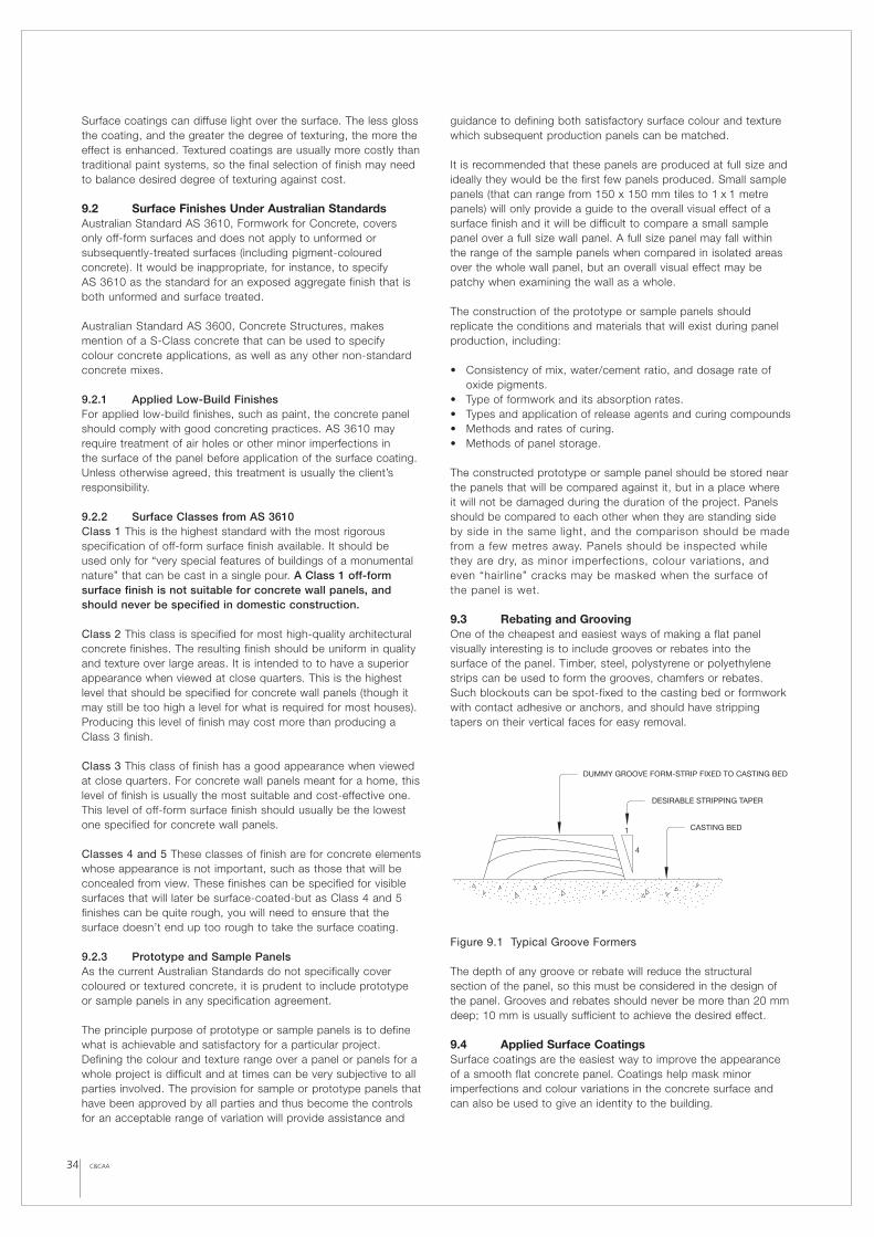
C&CAA34
Surface coatings can diffuse light over the surface. The less glossthe coating, and the greater the degree of texturing, the more theeffect is enhanced. Textured coatings are usually more costly thantraditional paint systems, so the final selection of finish may needto balance desired degree of texturing against cost.
9.2 Surface Finishes Under Australian StandardsAustralian Standard AS 3610, Formwork for Concrete, covers only off-form surfaces and does not apply to unformed orsubsequently-treated surfaces (including pigment-colouredconcrete). It would be inappropriate, for instance, to specify AS 3610 as the standard for an exposed aggregate finish that isboth unformed and surface treated.
Australian Standard AS 3600, Concrete Structures, makesmention of a S-Class concrete that can be used to specify colour concrete applications, as well as any other non-standardconcrete mixes.
9.2.1 Applied Low-Build FinishesFor applied low-build finishes, such as paint, the concrete panelshould comply with good concreting practices. AS 3610 mayrequire treatment of air holes or other minor imperfections in the surface of the panel before application of the surface coating.Unless otherwise agreed, this treatment is usually the client’sresponsibility.
9.2.2 Surface Classes from AS 3610Class 1 This is the highest standard with the most rigorousspecification of off-form surface finish available. It should be used only for “very special features of buildings of a monumentalnature” that can be cast in a single pour. A Class 1 off-formsurface finish is not suitable for concrete wall panels, andshould never be specified in domestic construction.
Class 2 This class is specified for most high-quality architecturalconcrete finishes. The resulting finish should be uniform in qualityand texture over large areas. It is intended to to have a superiorappearance when viewed at close quarters. This is the highestlevel that should be specified for concrete wall panels (though itmay still be too high a level for what is required for most houses).Producing this level of finish may cost more than producing aClass 3 finish.
Class 3 This class of finish has a good appearance when viewedat close quarters. For concrete wall panels meant for a home, thislevel of finish is usually the most suitable and cost-effective one.This level of off-form surface finish should usually be the lowestone specified for concrete wall panels.
Classes 4 and 5 These classes of finish are for concrete elementswhose appearance is not important, such as those that will beconcealed from view. These finishes can be specified for visiblesurfaces that will later be surface-coated-but as Class 4 and 5finishes can be quite rough, you will need to ensure that thesurface doesn’t end up too rough to take the surface coating.
9.2.3 Prototype and Sample PanelsAs the current Australian Standards do not specifically covercoloured or textured concrete, it is prudent to include prototype or sample panels in any specification agreement.
The principle purpose of prototype or sample panels is to definewhat is achievable and satisfactory for a particular project.Defining the colour and texture range over a panel or panels for awhole project is difficult and at times can be very subjective to allparties involved. The provision for sample or prototype panels thathave been approved by all parties and thus become the controlsfor an acceptable range of variation will provide assistance and
guidance to defining both satisfactory surface colour and texturewhich subsequent production panels can be matched.
It is recommended that these panels are produced at full size andideally they would be the first few panels produced. Small samplepanels (that can range from 150 x 150 mm tiles to 1 x 1 metrepanels) will only provide a guide to the overall visual effect of asurface finish and it will be difficult to compare a small samplepanel over a full size wall panel. A full size panel may fall withinthe range of the sample panels when compared in isolated areasover the whole wall panel, but an overall visual effect may bepatchy when examining the wall as a whole.
The construction of the prototype or sample panels shouldreplicate the conditions and materials that will exist during panelproduction, including:
• Consistency of mix, water/cement ratio, and dosage rate ofoxide pigments.
• Type of formwork and its absorption rates.• Types and application of release agents and curing compounds• Methods and rates of curing.• Methods of panel storage.
The constructed prototype or sample panel should be stored nearthe panels that will be compared against it, but in a place where it will not be damaged during the duration of the project. Panelsshould be compared to each other when they are standing sideby side in the same light, and the comparison should be madefrom a few metres away. Panels should be inspected whilethey are dry, as minor imperfections, colour variations, andeven “hairline” cracks may be masked when the surface of the panel is wet.
9.3 Rebating and GroovingOne of the cheapest and easiest ways of making a flat panelvisually interesting is to include grooves or rebates into thesurface of the panel. Timber, steel, polystyrene or polyethylenestrips can be used to form the grooves, chamfers or rebates.Such blockouts can be spot-fixed to the casting bed or formworkwith contact adhesive or anchors, and should have strippingtapers on their vertical faces for easy removal.
Figure 9.1 Typical Groove Formers
The depth of any groove or rebate will reduce the structuralsection of the panel, so this must be considered in the design ofthe panel. Grooves and rebates should never be more than 20 mmdeep; 10 mm is usually sufficient to achieve the desired effect.
9.4 Applied Surface Coatings Surface coatings are the easiest way to improve the appearanceof a smooth flat concrete panel. Coatings help mask minorimperfections and colour variations in the concrete surface andcan also be used to give an identity to the building.
DESIRABLE STRIPPING TAPER
4
1 CASTING BED
DUMMY GROOVE FORM-STRIP FIXED TO CASTING BED
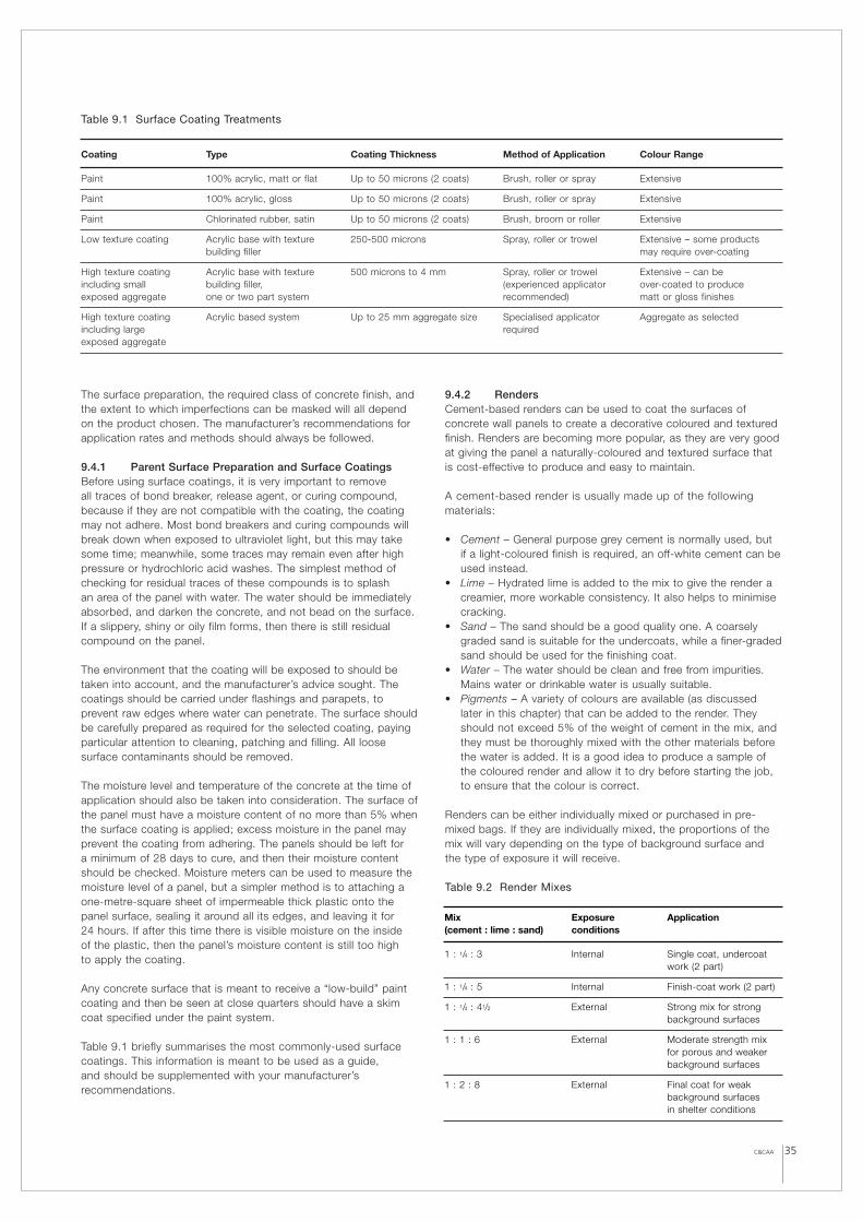
35C&CAA
The surface preparation, the required class of concrete finish, andthe extent to which imperfections can be masked will all dependon the product chosen. The manufacturer’s recommendations forapplication rates and methods should always be followed.
9.4.1 Parent Surface Preparation and Surface CoatingsBefore using surface coatings, it is very important to remove all traces of bond breaker, release agent, or curing compound,because if they are not compatible with the coating, the coatingmay not adhere. Most bond breakers and curing compounds willbreak down when exposed to ultraviolet light, but this may takesome time; meanwhile, some traces may remain even after highpressure or hydrochloric acid washes. The simplest method ofchecking for residual traces of these compounds is to splash an area of the panel with water. The water should be immediatelyabsorbed, and darken the concrete, and not bead on the surface.If a slippery, shiny or oily film forms, then there is still residualcompound on the panel.
The environment that the coating will be exposed to should betaken into account, and the manufacturer’s advice sought. Thecoatings should be carried under flashings and parapets, toprevent raw edges where water can penetrate. The surface shouldbe carefully prepared as required for the selected coating, payingparticular attention to cleaning, patching and filling. All loosesurface contaminants should be removed.
The moisture level and temperature of the concrete at the time ofapplication should also be taken into consideration. The surface ofthe panel must have a moisture content of no more than 5% whenthe surface coating is applied; excess moisture in the panel mayprevent the coating from adhering. The panels should be left for a minimum of 28 days to cure, and then their moisture contentshould be checked. Moisture meters can be used to measure themoisture level of a panel, but a simpler method is to attaching aone-metre-square sheet of impermeable thick plastic onto thepanel surface, sealing it around all its edges, and leaving it for 24 hours. If after this time there is visible moisture on the inside of the plastic, then the panel’s moisture content is still too high to apply the coating.
Any concrete surface that is meant to receive a “low-build” paintcoating and then be seen at close quarters should have a skimcoat specified under the paint system.
Table 9.1 briefly summarises the most commonly-used surfacecoatings. This information is meant to be used as a guide, and should be supplemented with your manufacturer’srecommendations.
9.4.2 RendersCement-based renders can be used to coat the surfaces ofconcrete wall panels to create a decorative coloured and texturedfinish. Renders are becoming more popular, as they are very goodat giving the panel a naturally-coloured and textured surface thatis cost-effective to produce and easy to maintain.
A cement-based render is usually made up of the followingmaterials:
• Cement – General purpose grey cement is normally used, but if a light-coloured finish is required, an off-white cement can beused instead.
• Lime – Hydrated lime is added to the mix to give the render acreamier, more workable consistency. It also helps to minimisecracking.
• Sand – The sand should be a good quality one. A coarselygraded sand is suitable for the undercoats, while a finer-gradedsand should be used for the finishing coat.
• Water – The water should be clean and free from impurities.Mains water or drinkable water is usually suitable.
• Pigments – A variety of colours are available (as discussedlater in this chapter) that can be added to the render. Theyshould not exceed 5% of the weight of cement in the mix, andthey must be thoroughly mixed with the other materials beforethe water is added. It is a good idea to produce a sample ofthe coloured render and allow it to dry before starting the job,to ensure that the colour is correct.
Renders can be either individually mixed or purchased in pre-mixed bags. If they are individually mixed, the proportions of themix will vary depending on the type of background surface andthe type of exposure it will receive.
Table 9.2 Render Mixes
Coating Type Coating Thickness Method of Application Colour Range
Paint 100% acrylic, matt or flat Up to 50 microns (2 coats) Brush, roller or spray Extensive
Paint 100% acrylic, gloss Up to 50 microns (2 coats) Brush, roller or spray Extensive
Paint Chlorinated rubber, satin Up to 50 microns (2 coats) Brush, broom or roller Extensive
Low texture coating Acrylic base with texture 250-500 microns Spray, roller or trowel Extensive – some productsbuilding filler may require over-coating
High texture coating Acrylic base with texture 500 microns to 4 mm Spray, roller or trowel Extensive – can be including small building filler, (experienced applicator over-coated to produce exposed aggregate one or two part system recommended) matt or gloss finishes
High texture coating Acrylic based system Up to 25 mm aggregate size Specialised applicator Aggregate as selectedincluding large requiredexposed aggregate
Table 9.1 Surface Coating Treatments
Mix Exposure Application(cement : lime : sand) conditions
1 : 1/4 : 3 Internal Single coat, undercoat work (2 part)
1 : 1/4 : 5 Internal Finish-coat work (2 part)
1 : 1/4 : 41/2 External Strong mix for strongbackground surfaces
1 : 1 : 6 External Moderate strength mix for porous and weakerbackground surfaces
1 : 2 : 8 External Final coat for weakbackground surfacesin shelter conditions
C&CAA36
Parent Surface Preparation The surface should be clean, and free of release agents, bond breakers, loose materials, and so on.Purpose-made bonding agents, applied in accordance withmanufacturer’s instructions, can improve adhesion. After initialpreparation, the parent surface should be dampened and allowedto dry immediately before rendering.
Table 9.3 Parent Surface Preparation
* Dash coats are used to provide a high-strength bond betweenthe parent surface and render coat. Dash coats contain one part cement to one or two parts sand. The coat is flicked andsplattered over the parent surface to produce a rough finish to‘key’ with the render coat.
Number of Coats One or two coats are usually required for mostconcrete panels. A minimum of three days should be allowedbetween coats. Undercoats are usually applied by trowel to athickness of 10 to 15 mm, and when firm should be raked orscratched to provide a key for the next coat. The final coat shouldbe no more than 10 mm thick.
Decorative Textured Finishes A variety of decorative texturedfinishes can be produced on the final coat with different finishingtechniques. The application of these finishes can be difficult, so acompetent tradesperson should do the job. Some of the finishesthat can be created include:
• Trowelled Finish – Created by skimming the final coat with awood float to produce a dense surface that can appear eithersmooth or notched in texture.
• Bagged – Created by rubbing damp hessian into the final coat.• Sponged – Created by mopping or sponging the unhardened
surface with a damp sponge. (Excess water from the spongeshould not be allowed to run down the wall.)
• Roughcast – The final coat is thrown or flicked onto the wallwith no additional rework.
Control Joints Cement-based renders can crack as a result of shrinkage or movement in the parent material. To minimisecracking, control joints should be placed to coincide with all joints in the parent material and with all locations wheremovement is likely to occur.
Curing All render coats (undercoats, dash coats, and final coats)should be kept damp for the first three days, or until the next coat is applied. Render should not be allowed to dry out quickly.Don’t render in direct sunlight or in exposed windy areas, as these conditions will dry out the render too quickly and reduce itsstrength. Fresh render should be protected for the first three daysafter application. If plastic sheeting is used for protection, ensurethat the sheeting does not touch the render, as this may lead todiscolouration. Internal render should not require any additionalprotection, as long as the building itself provides enough.
9.5 Integral Colouring and Texturing Concrete Another way of colouring or texturing a concrete panel is to colour or texture the concrete itself. Specific types of cement,aggregates and pigments can be used to give the panel aparticular colour or texture. Formliners or stamps can createpatterns on the surface of the panel. Colours and textures can be used in combination to create further variations.
The main constituents of concrete– the cement and theaggregates– play a large part in determining the final colour andtexture of the concrete. The colour can, if necessary, be modifiedfurther with mineral oxides.
Cement Cement is produced in grey, off-white, and white, and the colour you choose will have a direct effect on the colour of thesurface finish. Shades vary from manufacturer to manufacturer, so all the cement should come from one source to ensure aconsistent colour. White and off-white cements are moreconsistent in colour–but are also more expensive.
Aggregates In exposed aggregate finishes, the aggregates willinfluence the colour. The colour of the sand or fine aggregate will tend to dominate in lightly-exposed aggregate finishes (likeabrasive blasting, acid etching, or surface set retarders), while the colour of the coarse aggregates will dominate in more heavily-exposed finishes (such as water washing, heavy abrasive blasting,or honing and polishing).
Mineral Oxide Pigments Mineral oxides occur naturally in soiland rock, but they are also made synthetically. Synthetic oxidesare more widely-used because they are purer, more uniform,and better colouring agents. They are suitable for concretebecause of their chemical inertness: they do not react with the alkalies in cement, and they resist fading under exposure toweather and UV light.
Unlike dyes, which colour by staining, mineral oxides are insolublein water and colour the concrete by masking the cement matrix.They come in either powder or liquid, and are available in a widerange of colours.
9.5.1 ColouringIntegral Colouring Integrally coloured (or “colour-through”)concrete is concrete whose entire mass is coloured. If used in the correct proportions, the colouring oxides do not have asignificant effect on the strength of concrete. The amount ofoxide required is usually no more than 5% of the weight of thecement, and must be thoroughly mixed into the concrete mix to ensure consistency of colour.
Coloured Topping Slabs A monolithic topping is a layer ofconcrete that is placed on top a structural panel while theconcrete is still plastic, allowing the two to bond as they set and harden together into a single (or “monolithic”) element. Thisprocess reduces costs, as only the topping is coloured. Theconcrete topping usually consists of a 10 mm aggregate mix in a layer from 25 to 40 mm thick.
Dry Shake Toppings These toppings are created by hand-broadcasting a coloured dry-shake mixture over the surface of thepanel, following the evaporation of the bleed water. The surface isfloated (ideally by hand, though this may not be practical for largeareas). If a power float is used, care must be taken not to workthe coloured mixture into the surface of the panel–but even then,up to three coats may be required to produce a uniform finish.The coloured dry-shake toppings can be supplied pre-bagged;they contain mineral oxides, cement, sand, and a surfacehardener to strengthen the coloured surface.
Parent surface Building material Treatment
Smooth, strong High-strength concrete Scabble surface andapply dash coat *
Strong, porous Standard concrete Rake joints and apply dash coat *
Weak, porous Lightweight concrete, Dampen surfacerender undercoat
C&CAA 37
9.5.2 Off-form Texturing and StampingOff-form finishes are produced by casting concrete against amould, formliner, or form-face, which imparts its texture or patternto the surface of the concrete. The most common example of thistechnique is the standard smooth off-form finish. Off-form finishesare usually created on the lower face of the panel (the side on thecasting bed).
Stamping is a method of imprinting the concrete surface bypressing a stamping-mould or tool into it. Metal dies or rollers withtextured rubber mats can be used to replicate stonework. This kindof texturing is carried out on the upper (trowelled) face of the panel.
If you plan to use these types of finishes, keep the followingpoints in mind:
• Textured or replicated surface finishes can hide imperfectionsin the concrete surfaces.
• Good formliner materials include polystyrene, rigid plastics,fibreglass, polyurethane rubber, silicone rubber, steel platesand timber battens.
• The choice of formliner material should take into account thecomplexity of the formliner, the required surface texture, andthe number of times the liner is to be reused. Undercutsurfaces should be formed with flexible liners, such aspolyurethane or silicone rubber, so they can be strippedwithout damaging the panel.
• Joints created by abutting liners must be sealed well, asleakage can cause discrepancies in both the texture and thecolour of the rest of the panel.
• High temperatures can degrade the liner material. Prolongedexposure to direct sunlight can also damage formliners.
• Formliners should be cleaned thoroughly and coated with acompatible release agent before they’re reused.
9.5.3 Exposed Aggregate FinishesExposed aggregate finishes by definition reveal the aggregates(sand and stones) near the surface of the panel, which areotherwise hidden by a thin layer of cement paste (matrix). Thiscan be produced by various techniques that result in differentdepths of exposure and texture. Techniques include abrasiveblasting, acid etching, bush hammering, water washing, honingand polishing.
The type of aggregate used will affect both the density ofexposure and the colour of the final finish. Coarse aggregates areavailable in a wide range of colours, including white, black, greenquartz, dark grey basalt, brown and red gravels. Sands are alsoavailable in a range of colours. The cement matrix can also becoloured, using mineral oxide pigments that either complement or contrast with the aggregate.
Grading As defined by Australian Standard AS 2758.1 –Aggregates and Rock for Engineering Purposes – ConcreteAggregates, a coarse aggregate has a nominal size of not lessthan 5 mm, and a fine aggregate is smaller than 5 mm.
Abrasive Blasting Also called sandblasting or grit-blasting, thistechnique involves blasting the surface of the panel with sand,boiler slag or carborundum to remove a specified amount of thesurface. It produces a cost-effective finish with good weatheringcharacteristics.
There are four grades of abrasion:
• Brush Blasting – A light surface texture, similar to sandpaper,that does not reveal the coarse aggregates. The dominatingcolour is from the cement paste. This type of abrasion can beperformed after the panel is seven days old.
• Light Blasting – Exposes the fine aggregates (sand). Thedominating colour is from the sand, while the colour of thecement paste and coarse aggregates are secondary. This typeof abrasion can be performed when the panel is between 7and 45 days old.
• Medium Blasting – Exposes the coarse aggregates so that theyproject approximately 3 to 6 mm proud of the surface. Thecoarse aggregates should be hard enough not to be erodedduring the blasting. This type of abrasion should be performedbefore the panels are 7 days old, and the use of a chemicalretarder is recommended.
• Heavy Blasting – Results in the coarse aggregates projectingby up to a third of their diameters from the surface. To achieveuniformity, a higher-than-usual proportion of coarse aggregatesis usually required in the mix. The colour is dominated by thecoarse aggregates. This type of abrasion should be performedwithin 24 hours after casting, before the concrete has reachedfull hardness. The use of a chemical retarder is recommended.
Key points to consider for abrasive blasting:
• An experienced operator is necessary if the finish is to beuniform.
• The concrete must be placed and compacted well, as sandblasting will reveal any air pockets or uneven compaction.
• All panels must be abrasive-blasted at the same age, so thatthe finish will be uniform.
• After sand blasting, a light acid wash should be used to cleanthe surface.
Acid Etching In this method, a diluted acid is applied to theconcrete panel to remove the surface and expose the underlyingaggregates. The resulting textures usually resembles finesandpaper (though deeper etches are possible if it’s necessary to expose the coarse aggregate).
Key points to consider for acid-etching:
• An experienced applicator should always be used.• The concrete must be high-density, well-compacted, free from
cracks, and of sufficient thickness above the reinforcement.• The panel should be inclined during etching to prevent the acid
from pooling and etching some areas more than others.• After etching, the surface must be thoroughly washed with
water to remove residual acid.
Water Washing This technique is performed on the panel once ithas stiffened, but while it is still plastic. The top surface of thepanel is sprayed with water to wash away the cement paste andexposing the coarse aggregates underneath, so that they projectfrom the surface by up to a third of their diameters. The exposedaggregates are non-absorbent, so this finish is good at resistingstaining from air-borne grime, and is therefore low-maintenance.
Key points to consider for water washing:
• Aggregates should be 10-14 mm in diameter. Dense stones(such as river gravels, crushed granites, and rounded or cubicquartz) are the most suitable types.
• A gap-graded mix (a mix with just one size of aggregate)produces a more uniform surface than one with different sizesof aggregate.
• Stock piling specified aggregates will help maintain colourconsistency.
• The cement matrix can be coloured with mineral oxides thateither complement or contrast with the aggregates.
• Panels are usually cast face up so that they can be washedwhile the concrete is still plastic. If the panels are cast facedown, then a surface set retarder is used, and the panels arewashed immediately after they have been stripped.
• If the panels are cast face down, you can lay split rock,cobbles or thin brick tiles onto the casting bed after it hasbeen lined with surface set retarder (but before pouring). After the panel is stripped, the surface of the concrete can be washed away, exposing the rock, cobbles or tiles.
Honing and Polishing Honed or polished concrete is produced bygrinding the surface to expose the underlying aggregates. Theresulting finish can range from a dull honed finish to a high-lustrepolished finish. The type of aggregate determines the possiblelevel of polish. Most commercial quartzites, limestone and basaltcan be honed, but not highly polished. Granites (of variouscolours), quartz and river gravels composed primarily of quartzcan be highly polished. Keep in mind that this technique is usuallymuch more expensive than any of the others.
Key points to consider for honing and polishing:
• A gap-graded mix (a mix with just one size of aggregate)produces a more uniform surface than one with different sizesof aggregate.
• Some aggregates contain silica, which will react with thealkalies in the cement. This reaction produces an alkali-silicagel that swells with moisture and causes the concrete to crack.Common aggregates of this type that should be avoided arechert, chalcedony, common opal, acidic or vitreous volcanicstone (such as obsidian), and mica.
• Other aggregates (such as ironstone) can contain enough ironcontent to produce a rusty stain when exposed to theatmosphere, and should be avoided.
• Aggregates should be stock piled to better maintain colourconsistency. It is a good idea to produce test samples orprototypes of the specified finish for inspection to maintainquality.
• The cement paste can also be coloured using mineral oxides.(For details, refer to Section 9.5.1, “Colouring”.)
• Small, awkward areas, such as reveals and internal corners,can be polished using small hand tools.
• Care should be taken when polishing the edges or corners ofthe panel, as they are vulnerable to chipping. A chamfer orbevel should be provided along these edges if possible.
9.6 Decorative Exterior Façade Mouldings Decorative exterior façade mouldings can be used to add interestto the exterior of a concrete panel home. A large range of theseproducts is available for improving the appearance of a plain,flat wall:
• Window mouldings (heads, sills, and reveals)• Door mouldings• Stringer, keystone and quoin profiles• Parapet profiles• Corbel mouldings• Arch mouldings
The particular product range and profiles will vary with the supplier,but these products are usually made of a lightweight core materialreinforced with a hard coating of resin and/or cementiciousmaterial. They are typically mechanically fixed to the concretepanels, and their joints are sealed. The assembly can then bepainted, or a coating applied to match the rest of the wall.
Preparation of the panel surface and installation of the mouldingsor profiles should be in accordance with the supplier’s instructionsto ensure a long-lasting façade detail.
Lightweight column façades can also be used to clad supportingtimber or steel columns. These column façades can be installedon both load-and non-load-bearing columns. Again, installationshould be in accordance with the supplier’s instructions to ensurea long-lasting façade.
38 C&CAA
Figure 9.4 Decorative External Façade Mouldings: ColumnMouldings. Image supplied by www.unitex.com.au.
Figure 9.2 Decorative External Façade Mouldings: WindowMouldings. Image supplied by www.unitex.com.au.
Figure 9.3 Decorative External Façade Mouldings. Imagesupplied by www.unitex.com.au.