walter wuenschieee nss and mic30 october 2012 applications of normal-conducting rf linear...
TRANSCRIPT
Walter WuenschIEEE NSS and MIC30 October 2012
Applications of Normal-conducting RF linear accelerators
(industry perspective)

Walter WuenschIEEE NSS and MIC30 October 2012
In this presentation I will consider the relationships between nc (normal conducting) linear collider projects and industry. I approach it from two distinct perspectives:
• Consider how the technology developed for nc linear colliders may be applied to existing and future industrial and industrial-use linacs.
• Consider how nc linear collider studies have stimulated industrial development which may then be used for other applications.
Linear collider study Industrial linacs
Industry Other applications
Objective

Walter WuenschIEEE NSS and MIC30 October 2012
More specifically I will:
• Consider how the technology developed for nc linear colliders may be applied to existing and future industrial and industrial-use linacs.
• What are the important dependencies which influence high-gradient linac design?
• Which industrial linacs might benefit from higher gradients, frequency and precision? I discuss an example, a medical accelerator – TULIP
• Consider how nc linear collider studies have stimulated industrial development which can be used in other applications.
• I will address this with a “case study” - the of development of micron-precision machining with and within VDL.
Outline

Walter WuenschIEEE NSS and MIC30 October 2012
A reminder of our linear collider application – 100 MV/m accelerating structures
CLIC accelerating structure prototype
NEXTEF test area at KEK

Walter WuenschIEEE NSS and MIC30 October 2012
Accelerating gradient test status: 4-9-2012

Walter WuenschIEEE NSS and MIC30 October 2012
There are two key issues which drive normal conducting rf linac parameters:
• Accelerating structures• rf power sources
Progress on achieving high-gradients for nc linear colliders has been as much a story of developing high peak power sources (be they klystrons or two-beam) as of accelerating structures.
Consequently the cross-flow of advances between NC linear collider projects and industry has been, and has to be, for both rf power production and for acceleration.
I will primarily cover the technology related to the accelerating structures.
But please bear in mind that power sources are an equally important issue, so please pay close attention to the next speaker!
The importance of power sources

Walter WuenschIEEE NSS and MIC30 October 2012
rf power sources
We are particularly excited by the progress in the industrial development of:- 5 to 30 MW C-band (5.7 GHz) klystrons- 5 to 50 MW X-band klystronscombined with compact pulse compressors.
The low end of the power range is proving crucial to significantly bringing down the “cost of entry” to high-gradient nc systems. Modulator voltages are lower etc.

Walter WuenschIEEE NSS and MIC30 October 2012
The high-energy physics community has supported R&D on increasing the gradient in normal conducting linacs.
• With the higher gradient comes naturally higher frequency. • So with higher gradient also comes the need for higher precision.
I’ll present the basic scaling laws which drive these trends.
Then I will try to put these trends into the context of some industrial and industrial-use accelerator applications.
Higher Gradient and what comes with it
Walter WuenschIEEE NSS and MIC30 October 2012
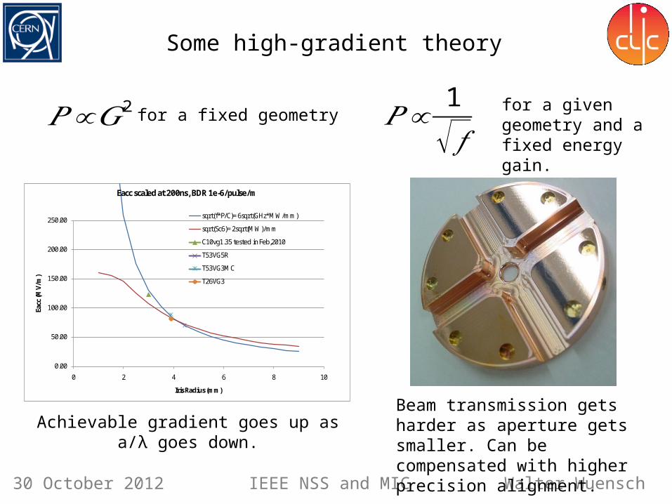
Some high-gradient theory
𝑃 ∝𝐺2 𝑃 ∝1
√ 𝑓for a given geometry and a fixed energy gain.
0.00
50.00
100.00
150.00
200.00
250.00
0 2 4 6 8 10
Eacc
(MV/
m)
Iris Radius (mm)
Eacc scaled at 200ns, BDR 1e-6/pulse/m
sqrt(f*P/C)= 6sqrt(GHz*MW/mm)
sqrt(Sc6)= 2sqrt(MW)/mm
C10vg1.35 tested in Feb,2010
T53VG5R
T53VG3MC
T26VG3
Achievable gradient goes up as a/λ goes down.Beam transmission gets harder as aperture gets smaller. Can be compensated with higher precision alignment.
for a fixed geometry

Walter WuenschIEEE NSS and MIC30 October 2012
Possible applications
We can identify other applications which would benefit from high-gradient technology:
• Linacs for proton and carbon ion cancer therapy.• High repetition rate FELs (Free Electron Lasers) for the ‘photon-science’ community.
Users of these machines encompass biology, chemistry, material science and many other fields.
• Compton-scattering gamma ray sources providing MeV-range photons for laser-based nuclear physics (nuclear-photonics) and fundamental processes (QED studies for example). There are also potential applications such as nuclear resonance fluorescence for isotope detection in shipping containers and mining.
• Classical industrial linacs.
Walter WuenschIEEE NSS and MIC30 October 2012
Now a look at a high-gradient for a medical application.

Characteristics of a therapeutical beamBasics on Hadrontherapy:
Charged hadron beam that loses energy in matter
27 cm
Tumourtarget
200 MeV - 1 nA protons
4800 MeV – 0.1 nA carbon ions(radioresistant tumours)
tail
httt://global.mitsubishielectric.com/bu/particlebeam/index_b.html
Courtesy of PSI
Depth-dose distribution

Walter WuenschIEEE NSS and MIC30 October 2012
Synchrotron-based proton therapy at CNAO in Pavia

• Cell Coupled Linac • RF frequency: 5.7 GHz• 18 accelerating modules - Length of each module ~ 1.3 m• High gradient : 40 MV/m (TERA+CLIC collaboration)
The cyclinac: cyclotron + high frequency linacAccelerators for Hadrontherapy
CELL COUPLED LINAC
Cell Coupled Linac Standing-wave structure RF frequency: 5.7 GHz 2.5 ms-long pulse at 300 Hz (CArbon BOoster for Therapy in Oncology)
CABOTO
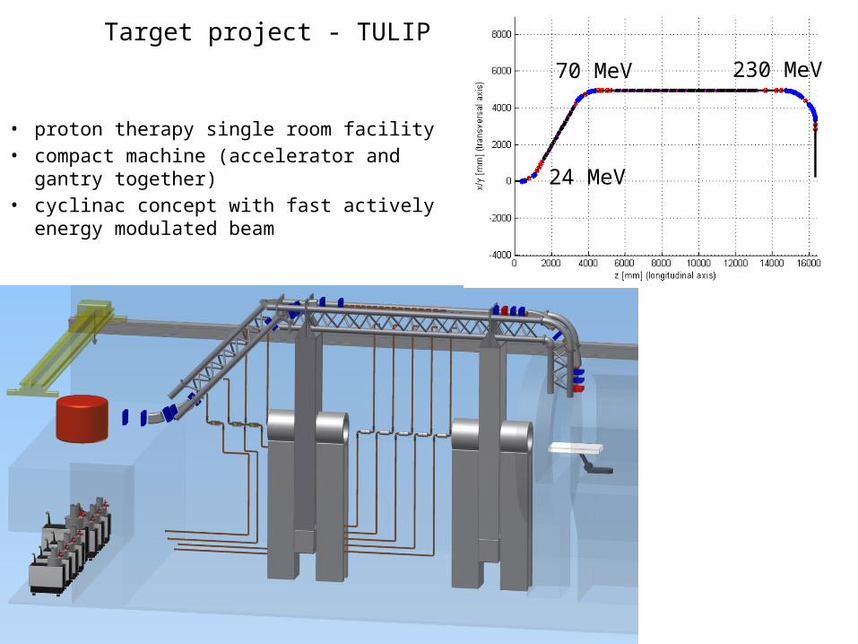
Target project - TULIP
• proton therapy single room facility• compact machine (accelerator and gantry
together)• cyclinac concept with fast actively energy
modulated beam
230 MeV70 MeV
24 MeV

The current design of the basic cell geometry for low velocity acceleration
(still under optimization)
And a micron-precision CLIC cell
We plan to improve it with a novel high-gradient backward wave structure an our standard high-gradient technology:

Walter WuenschIEEE NSS and MIC30 October 2012
For rf enthusiasts – here you can see how we design for high gradient
Surface electric field Surface magnetic field
Modified Poynting vector
SS Im6
1Re cSOur current understanding of
high-gradient limits

Walter WuenschIEEE NSS and MIC30 October 2012
Some other examples of high-gradient and high-frequency normal conducting linac applications

GdA_LINAC12_XXVI Linear Accelerator Conference, Tel Aviv, Israel, September 9-14, 2012 19
Mark-0 X-band photo-injector
6 kG Solenoid Magnet
5.5 cell RF Gun
Coupler Cell
F = 11.424 GHz, 5.5 cells, π-mode Earlier version tested at 200 MV/m
with 250 ns RF pulse. Coupling factor β ≈ 1.7
Photo-injector assembly
Water Cooling
Courtesy ofA. Vlieks
Improved version under construction MARK-1• 5.59 cells • > 25 MHz mode separations• elliptical irises • racetrack coupler
Cathode
Splitter/Input Waveguide
SLAC

GdA_LINAC12_XXVI Linear Accelerator Conference, Tel Aviv, Israel, September 9-14, 2012 20
Transverse Cavity Diagnostics
BC1250 MeV
YAGS2
Laser OFFσE/E < 12 keV
RF deflector ON
timeenergy
YAGS2
Laser: 40 µJσE/E 45 keV
The Transverse Cavity (TCAV)
technique is now a well established
diagnostic tool at the X-ray FELs to
measure sub-ps temporal bunch
profiles.
e-
sz
bd bs
D 90°
V(t)
RF‘streak’
sy
The diagnostics is further enhanced if the deflected
beam is observed on an energy spectrometer
screen, where the energy dispersion is in the plane
perpendicular to the RF deflection. The dispersion
properties of the dipole allow for the complete
characterization of the energy distribution of each
bunch slice reconstructing the longitudinal phase
space.
Energy profile and slice energy spread measurements with
TCAV at LCLS
L1S
L1X
DL1135 MeV
L0
gun
3 wires3 OTR
Laserheater
TCAV0
LCLS injector layout
Courtesy ofP. Krejcik, P. Emma, H. Loos
Principle of operation
SLAC

GdA_LINAC12_XXVI Linear Accelerator Conference, Tel Aviv, Israel, September 9-14, 2012 21
UCLA Hybrid Photoinjector
SW high gradient RF gun section+
TW low gradient section
both fed on-axiswith a common coupling cell
• More compact than a split system• Nearly RF matched – no isolator• Avoids post-gun bunch lengthening• Strongly longitudinally focused with the TW
section performing as velocity bunching (90°
phase shift between SW cell and input
coupler)
High accelerating field on axis, 200 MV/m peak very high brightness beams. X-band scaled from an existing S-band unit, preserving acceleration and
transverse dynamics. Tens of fs beams at 3.5 MeV with sub-0.1 mm-mrad emittance at 7 pC Applications: PWFA, coherent Cerenkov rad., electron diffraction
SW 2.6-cell gun
Courtesy ofA. Valloni, J. Rosenzweig

GdA_LINAC12_XXVI Linear Accelerator Conference, Tel Aviv, Israel, September 9-14, 2012 22
72 Cells
2 Coupl.
2 Regions for monitoring wakefields
Accelerating Structure
Parameter Value Units
Working frequency 11.992 GHz
Overall length 0.965 m
Active length 0.75 m
Iris diameter (average) 9.1 mm
Group velocity variation 1.6 - 3.7 %
Average grad. with 29 MW RF 40 MV/m
Filling time 100 ns
Pulse repetition rate 50 Hz
Structure type72 cells, CG, 5/6 ,no HOM damping

GdA_LINAC12_XXVI Linear Accelerator Conference, Tel Aviv, Israel, September 9-14, 2012 23
LLNL Gamma-ray source
Two XL4 Klystrons + RF pulse compressor
Six SLAC T53 accel. str. (@70 MV/m)
Mark-1 Photo-injector
Courtesy ofC. Barty
g-rays 0.5 - 2.5 MeV(1020 ph/sec/mm2/mrad2/0.1%bw)
forNuclear Resonance Fluorescence (NRF)

X-band linac concept
• 3 of 4 standaard 3 m lange S-band versnelstructuren die een 5 ps electronbunch versnellen tot 240 MeV• X-band linearizer remt bundel af met 40 MeV• bunchcompressie tot 1 ps in magnetische chicane BC1• 2 X-band main linac secties, elk bestaande uit 8 0.5 m lange versnelstructuren
met versnelgradient van 100 MV/m • bunchcompressie tot 50 fs in magnetische chicane BC2• magnetische dogleg naar undulator

Walter WuenschIEEE NSS and MIC30 October 2012
An incomplete, but on-going attempt at a summary of industrial rf linacs
Comments and help requested to expand this list! This is just the beginning in a long program of work.
Typical parameters Examples SourceMedical
Cancer therapyElectron 6 MeV, X-band, electrons Cyberknife, Accuthera Inc. X-band 6, http://www.accuray.com/Proton
Fixed linac 30-230 MeV protons, S-band LIGHT, ADAM SA http://adam-geneva.com/Rotating linac 30-230 MeV protons, S-band TULIP, TERA Foundation https://indico.cern.ch/conferenceDisplay.py?confId=178002
Carbon ion 300-430 MeV/u carbon ions CABOTO, TERA Foundation Reviews of Accelerator Science and Technology, Chao and Chou eds.Diagnostics and imaging
Radio-pharmacuticsIsotope production PET tracers (with linac?)
SterilizationMedical equipment 5 to 10 MeV, 25 to 700 kW beam power HammBlood irradiation 2 MeV, X-band, electrons Radiabeam X-band 5
Non-Destructive Testing (NDT)
On-site X-ray 1-9 MeV, X-band electronsAccuthera, Mitusbishi Chemical, Hitachi Engineering X-band 6
Neutron
Inspection
Cargo X-ray 1-9 MeV
American Science and Engineering, L-3 Communications, Rapiscan Systems, Science Application International Corporation, Smiths Detection, Varian, Nuctech http://www.nuctech.com
Food irradiation 5 to 10 MeV, 25 to 700 kW beam power Hamm
Waste treatment 5 to 10 MeV, 25 to 700 kW beam power Hamm
Material processingCross-linking and polymerization 5 to 10 MeV, 25 to 700 kW beam power Hamm
Walter WuenschIEEE NSS and MIC30 October 2012
How CLIC has worked with industry:Case study of VDL

Walter WuenschIEEE NSS and MIC30 October 2012
As we have seen, high-gradients drive us toward linacs which have higher rf frequency and consequently tighter mechanical tolerances.
Linear colliders main linacs also need to preserve the quality of the low emittance beams also driving us to micron precision.
In addition the acceleration of multi-bunch trains in linear colliders to gain rf-to-beam efficiency has required incorporating 3-D features in our parts.
This is challenging!
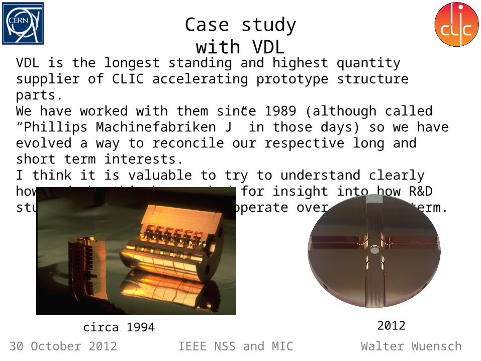
I will now consider a case study of a long-standing industrial collaboration CLIC has had with VDL in the production of micron-precision copper parts for our high-gradient prototypes.
The following slides have been prepared in collaboration with VDL and representatives from the firm are in the audience.
Micron Precision, 3-D Geometries and Industry
Walter WuenschIEEE NSS and MIC30 October 2012
VDL is the longest standing and highest quantity supplier of CLIC accelerating prototype structure parts.We have worked with them since 1989 (although called “Phillips Machinefabriken J” in those days) so we have evolved a way to reconcile our respective long and short term interests.I think it is valuable to try to understand clearly how and why this has worked for insight into how R&D studies and industry can cooperate over the long term.
Case study with VDL
circa 1994 2012

Walter WuenschIEEE NSS and MIC30 October 2012
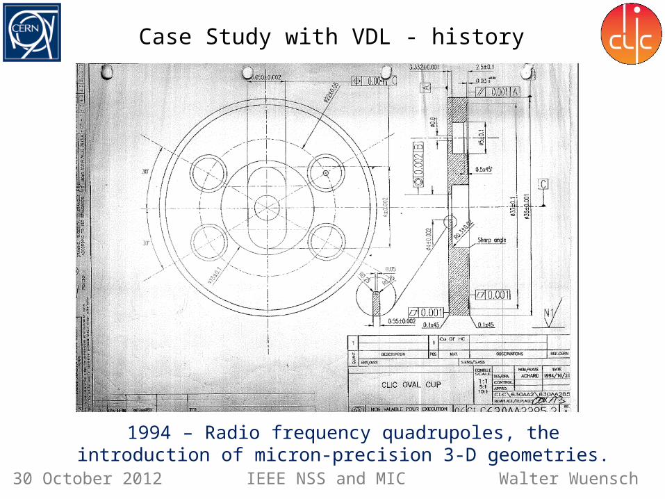
Case Study with VDL - history
1989 – 30 GHz micron-precision accelerating structures
Walter WuenschIEEE NSS and MIC30 October 2012
Case Study with VDL - history
1994 – Radio frequency quadrupoles, the introduction of micron-precision 3-D geometries.

An Asset Test of the CLIC Accelerating Structure, PAC2000
Higher-order mode damping demonstration in
ASSET 1999
150 cells/structure, 15 GHz
24 cells/structure, 12 GHz(loads not implemented yet)
Then
Now
Double band circuit model

Walter WuenschIEEE NSS and MIC30 October 2012
It’s not always been easy…

Walter WuenschIEEE NSS and MIC30 October 2012
• 30 mm disks• circular iris• no waveguides
1990’s 2000’s
• 80 mm disks• elliptical iris• closed waveguides
2010’s
• Due to shift from brazing to bonding higher demands on surface finish and flatness•Open waveguides
Evolution of requirements

Walter WuenschIEEE NSS and MIC30 October 2012
Evolution of the micron-precision market
The market for micron precision parts has evolved over the last decades.Linear colliders are not alone.
1970’s 1980’s 1990’s 2000’s 2010’s
Optical recording
Imaging Optics
Mirror optics Injection molding
of contact lenses Freeform optics
Optical recording was the driving force to achieve higher accuracies
Form accuracy: 150 nm 50 nm
Roughness Ra : 5 nm 2 nm

Walter WuenschIEEE NSS and MIC30 October 2012
Evolution of machining capability
Up to the 1980’s 1980’s - 1990’s 2000’s - 2010’s• Larger machines• Multiple axis ( X/Y/Z and C)
Future ?• Intelligent machines ?•Robotisation ?
• Pallet machining?•Robotisation ?
First machines at research institutes and
universities
Start of industrialization• Optical recording• contact lenses
Single point diamond turning
Up to the 1990’s 1990’s - 2000’s 2010’s Future ?
Ultra precision diamond milling (lagging more than a decade behind on turning)
Limited to fly cutting• mirror optics• Laser scanner mirrors
First proto type machines• Micro fluidics• Accelerator parts
Milling as add-on on lathes• Lens arrays• Intra ocular lenses
Walter WuenschIEEE NSS and MIC30 October 2012
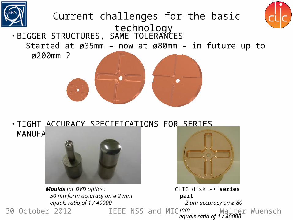
• BIGGER STRUCTURES, SAME TOLERANCESStarted at ø35mm – now at ø80mm – in future up to ø200mm ?
• TIGHT ACCURACY SPECIFICATIONS FOR SERIES MANUFACTURING
Moulds for DVD optics : 50 nm form accuracy on ø 2 mm equals ratio of 1 / 40000
CLIC disk -> series part 2 µm accuracy on ø 80 mm equals ratio of 1 / 40000
Current challenges for the basic technology

Walter WuenschIEEE NSS and MIC30 October 2012
Broadening the involvement with industry
• TIME TO MARKETCo-development with industry to enable swift innovations
• INDUSTRALISATION• Early industry involvement for cost control & risk reduction• Co / Redesign for manufacturability
Straight mode converter VDL redesign from 16 to 2 parts

Walter WuenschIEEE NSS and MIC30 October 2012
We are moving industrialization up the system scale – from machined components, to complete rf structures perhaps all the way up to complete modules for example. • INCREASED COMPLEXITY REQUIRES HIGHER LEVEL OUTSOURCING
Using experience of industry to securing shortest cycle time to end-product
Complex modules to be manufactured in series
Broadening the involvement with industry

Walter WuenschIEEE NSS and MIC30 October 2012
How working on CLIC can be in VDL’s interest
Linear colliders are very long term projects with many scientific and technical uncertainties and for which finding funding will be challenging. How can this match with the world of quarterly profit reports?
VDL’s drivers to invest in a long term relation is a combination of three crucial factorsAll three must be in place to secure the long term cooperation with institutes like CERN
• precision technology, and (re)design for manufacturability are key competences of VDLwhich must evolve continuously to serve its mainstream customers and maintain industryleadership. CERN is regarded as a crucial driver being ahead of VDLs mainstream industry• VDL recognizes the long term business potential of high gradient accelerator projects andapplications• Cultural and Value fit. VDL is a large privately owned company, 100% equity funded, whereprofit maximization is not the only goal in life. Open culture of VDL fits well with research institutions and universities.

Walter WuenschIEEE NSS and MIC30 October 2012
Acknowledgments - I would like to personally thank Hans Priem and Mathieu Breukers from VDL and Gerardo D’Aurio from Sincrotrone Trieste for help in preparing slides for this presentation.
Linear collider study Industrial linacs
Industry Other applications
I hope that I have given you some insight how normal conducting accelerating structure development for linear colliders has interacted with industry and how this may evolve – thank you!
Summary