warm dense matter science using intense ion beams · warm dense matter science using intense ion...
TRANSCRIPT

Warm Dense Matter Science Using Intense Ion Beams
* This work was performed under the auspices of the U.S. Department of Energy by Lawrence Livermore National Security, LLC, Lawrence Livermore National Laboratory under Contract DE-AC52-07NA27344, by LBNL under Contract DE-AC02-05CH11231, and by PPPL under Contract DE-AC02-76CH03073.
The Heavy Ion Fusion Science Virtual National Laboratory
John J. Barnard1, Ronald C. Davidson3, Alex Friedman1, Erik Gilson3, Igor Kaganovich3, Andrew Ng4, David P. Grote1, Qing Ji2, Arun Persaud2,
Peter A. Seidl2, Thomas Schenkel2 1. Lawrence Livermore National Laboratory 2. Lawrence Berkeley National Laboratory
3. Princeton Plasma Physics Laboratory 4. Consultant
Frontiers in Plasma Physics Town Hall Meeting Bethesda, Maryland June 30 – July 1, 2015
The Heavy Ion Fusion Science Virtual National Laboratory LLNL-PRES-673751

Slide 2
Several current and future facilities will use intense ion beams to explore warm dense matter science
HIAF (China, ~2022)
Bella-i (US ~2018?) (see Esarey, Schenkel, Geddes talks)
(Germany ~2018)
NDCX-II (US, 2015)
Examples of accelerator-based ion beam facilities:
JLF (US, present day)
Examples of laser-based ion beam facilities:
Trident (US, present day) + ...

Slide 3
Large sample sizes compared to diagnostic resolution volumes (~ 1's to 10's µ thick by spot sizes ~ 1 mm diameter)
Uniformity of energy deposition A benign environment for diagnostics (low debris and radiation background) High shot rates (~2/minute) to facilitate calibration and experimental setup Precise control of energy deposition (and ability to do energy accounting by measuring
transmitted beam) Small shot-to-shot energy variation in energy and intensity Ability to heat all target materials (conductors and insulators, foams, powders, ...) Pulse long enough to achieve local thermodynamic equilibrium (Te = Ti) Very small beam induced magnetic fields (no high energy electrons generated) High availability for experiments Facility can be a training ground for limited availability experiments on facilities such as
LCLS, Rochester, NIF
Accelerator driven ion beams have unique characteristics for WDM experiments
X-ray heating, direct laser heating, laser-produced ion heating, pulsed power heating, accelerator based ion heating each have non-ideal aspects. Multiple approaches are needed for validation.

Slide 4
Neutralized Drift Compression Experiment II (NDCX-II) has recently been commissioned (2015).
A new He ion source has been installed allowing higher fluences and Bragg Peak heating at 1.2 MeV
NDCX-II beam: 1.2 MeV, ~ 70 nC (5 x 10¹¹ ions), ~ 1ns ~ 1 mm spot diameter
Targets: solids or foams; conductor or insulators; For foam targets: pore size: ~ nm to µm density: 1 to 100% solid
Diagnostics: Optical pyrometry, streak cameras, VISAR, energy analyzer ...

Slide 5
Ion beam
In simplest example, target is a foil of solid or “foam” metal
Example: Ne
Enter foil Exit foil
!dE/dX " !T
!
"1Z 2
dEdX
Energy loss rate
Energy/Ion mass
(MeV/mg cm2)
(MeV/amu) (dEdX figure from L.C Northcliffe and R.F.Schilling, Nuclear Data Tables, A7, 233 (1970))
Fractional energy loss can be high and uniformity also high if operate at Bragg peak (L. R. Grisham, Physics of Plasmas, 11, 5727 (2004). )
zr!cs t
!z!
cs
"#
z!
!3cs t c
!z!z!!3cs t
Maximize uniformity and efficiency by placing center of foil at or near Bragg peak

Slide 6
Ion beams can explore a variety of topics in WDM science
Areas of investigation (in context of NDCX-II accelerator) include:
•! Equation of state
•! Ion stopping power
•! Electrical and thermal conductivity
•! Ion driven shock dynamics

-4 -2 0 2 40.0
0.5
1.0
1.5
2.0
2.5
Longitudinal position z HmL
DensityrHgêc
m3 L
-4 -2 0 2 40.0
0.5
1.0
1.5
2.0
2.5
Longitudinal position z HmL
DensityrHgêc
m3 L
Upper set: LEOS without Maxwell construction Lower set: QEOS without Maxwell construction (Magenta: Tmax; Blue:150 nm; Green: 450 nm; Red: 1500 nm)
Upper set: LEOS without Maxwell construction Lower set: QEOS without Maxwell construction (Magenta: dz/dt of outermost zone; Blue:150 nm; Green: 450 nm; Red: 1500 nm)
Pyrometry VISAR
Upper (in each pair): QEOS without Maxwell construction Lower (in each pair): LEOS without and Maxwell construction (Snapshots separated by 0.1 ns
Multi-frequency (upper left) and multi-angle pyrometry measurements, together with multi-frequency Visar measurements (upper right) can distinguish between EOS candidates.
X-ray imaging of density profile (lower, shown at 10 different snapshots) can distinguish between EOS
Density
-4 -2 0 2 40.0
0.5
1.0
1.5
2.0
2.5
Longitudinal position z HmL
DensityrHgêc
m3 L
0 2 4 6 8 100.0
0.2
0.4
0.6
0.8
1.0
1.2
time HnsL
kTatcritdensHeVL
kT a
t crit
ical
den
sity
(eV
)
time (ns)
0 2 4 6 8 100.00.20.40.60.81.01.21.4
time HnsL
dzêdta
tcritdensHcmê–sL
time (ns)
dz/d
t at c
ritic
al d
ensi
ty (c
m/u
s)
(1.2 MeV, 12 J/cm2, 1 ns Li+ ion beam on Al target)
Measurements of electron temperature, density and hydrodynamic expansion velocity allow distinction between EOS models
HYDRA1 simulations:
1. M. M. Marinak et al, Phys. Plasmas 8, 2275 (2001)

Slide 8
Ion stopping rates (dE/dX) in heated matter can be measured using NDCX-II both directly and indirectly
An electrostatic energy analyzer (EEA) or other direct energy diagnostic may be used to measure energy of transmitted ion beam.
He+
Indirect method: measure neutron production on deuterated carbon (plastic CD2) target or (better) targets with known fraction of D and T.
He+ + D ! "knock-on" D (~100 kV) + D ! n + charged particles
Number of created neutrons proportional to 1/(dE/dX|He) x 1/(dE/dX|D) since the lower the dE/dX the greater chance a knock-on collision will occur and the greater chance a neutron producing reaction can occur.

Slide 9
Thermal conductivity in heated matter is another area of investigation
~ion range#
This experiment will be carried out at low ion intensities, so that the material is below the vaporization temperature
Pyrometer/ Streak camera
Ion
Beam
Tamper
Thermal conductivity can be measured by determining time for heat to reach various depths in foils thicker than range of ions
Ion beam heats tamper and rest of target nearly uniformly. Thermal wave from higher temperature tamped region 'breaks out" at various times depending on depth of grooves and heated material conductivity.

Electrical conductivity can be measured using magnetic diffusion time
Transparent glass slide with hole for beam (~ 2 mm thick) Glass fiber for measurement
of Magnetic field using Faraday effect (as carried out by H. Yoneda, 2012, a collaborator with our group)
Aluminum foil (5 -10 µ thick)
Fine wires (10 - 20 µ thick)
A voltage is rapidly pulsed across the fine wires. Ion beam heats foil and magnetic field diffuses through foil, depending on resistivity of heated foil. Magnetic field is measured using Faraday effect through the optical fiber.
Ion beam
Slide 11
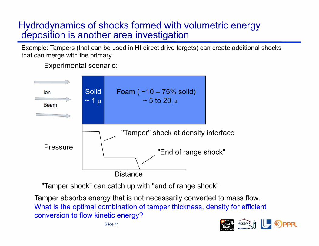
Hydrodynamics of shocks formed with volumetric energy deposition is another area investigation
Experimental scenario:
Solid ~ 1 µ#
Foam ( ~10 – 75% solid) ~ 5 to 20 µ
"End of range shock" Pressure
"Tamper" shock at density interface
"Tamper shock" can catch up with "end of range shock" Distance
Tamper absorbs energy that is not necessarily converted to mass flow. What is the optimal combination of tamper thickness, density for efficient conversion to flow kinetic energy?
Example: Tampers (that can be used in HI direct drive targets) can create additional shocks that can merge with the primary

Slide 12
1.! Phase transitions: in particular liquid-vapor phase transition and the complete boundary between the regions, and critical points. (Critical point is poorly known for many of the refractory metals). (Solid-liquid and solid-solid phase transitions are also of interest for some material.)
2.! Phase transitions from metal to insulator and insulator to metal.
3.! Transition between transparent and opaque, as in transient darkening
4.! Unusual plasma configurations, such as positive/negative plasmas (with low concentrations of electrons) as in halogens and some metals such as gold and platinum at temperatures above 0.4 eV.
5.! Fragmentation/fracture mechanics of materials under extreme conditions (e.g. carbon, silicon)
6.! Droplet formation and the role of surface tension in rapidly expanding heated metals
7.! Plasma physics of neutralized and unneutralized intense ion beams (see Peter Seidl poster and Erik Gilson talk, this meeting).
Other areas of interest to investigators of WDM and fusion science that may be explored using intense ion beams

Slide 13
Conclusions
Warm dense matter science using intense ions is an area rich in plasma physics.
Ion beams can support a wide range of experimental investigations: •! Equation of state in the WDM regime •! Ion dE/dX in heated materials •! Conductivity in heated matter •! Hydrodynamic coupling of ion beams using volumetric energy deposition •! Other areas include: phase transitions (solid-solid, solid-liquid, and liquid
-vapor); metal to insulator and insulator to metal transitions; opacity transitions (such as from transparent to opaque); fragmentation/fracture mechanics for materials under extreme conditions; droplet formation and surface tension; unusual plasma configurations; and intense beam dynamics (non-neutral as well as neutralized).
NDCX-II offers a different approach to produce WDM states in the Laboratory (beyond lasers, laser-produced ions, X-rays, etc.) Multiple approaches are needed for validation. Other WDM facilities such as LCLS MEC, FAIR, Bella-i, etc. will be complementary.