warnings and cautions for mqv series flow controllers digital … · 2019-08-01 · japanese...
TRANSCRIPT

● Never allow gases that are within explosive limits to pass through this device. Doing so might result in an explosion accidents.● Never use a device for oxygen gas if it is not a special oil-free oxygen gas model. Doing so could cause the gas to ignite.Even if gas-contacting sections have been treated to be oil-free, they cannot be used for oxygen if they have previously been used for some other gas.● If the device is used for burner air-fuel ratio control, take the necessary countermeasures with the equipment to prevent the occurrence of backfire and to avoid any influence to the device even if backfire occurs. Pressure increase or fire in the pipes caused by the backfire of the burner could damage the controller.● Prevent foreign matter from entering the device. If rust, water droplet, oil mist, or dust in the pipes enters the device, measurement or control error or damage might occur.If there is a possibility of foreign matter entering the device, provide a filter, strainer or mist trap capable of eliminating foreign matter 0.1 μm or greater in diameter at the upstream. Be sure to inspect and replace the filter at regular intervals.● Use the device within the operating differential pressure range. Also, do not subject it to pressure beyond the rated pressure resistance range. Doing so might damage it.● Do not subject this device to pressure beyond its rated pressure resistance. Doing so might result in damage.● Be sure to use within the flow rate range stated in the product specifications. To prevent excessive flow rate, design instrumentation that includes, as appropriate, supply pressure management, a throttle valve, etc. Exceeding the upper limit of the range may result in display and output values that are considerably lower than the actual flow rate.● If a problem with this device could result in damage, include appropriate redundancy in the system design. ● The valve on this device cannot completely shut a flow off. If complete shutoff is required, provide a shutoff valve separately. When the external valve is closed, it is necessary also to fully close the valve of the device using either of the following methods:・ Set the flow rate setpoint to zero.・ Make the valve operation mode to fully closed.
If this valve remains in normal control status when the external shutoff valve is closed (zero flow rate), there will be an excessively large flow as soon as the external shutoff valve is opened. For the MQV0050(J/K), MQV0200(J/K), and MQV0500(J/K), if the external shutoff valve is closed continuously for 5 minutes or more in control mode or with the valve forced fully open, the valve overheating limit (AL71) will be activated and the current to the valve will be forcibly limited.
● Before connecting pipes with Swagelok or VCR connections, check the precautions in the instruction provided by the connecting joint manufacturer. When separately purchasing a connecting joint, use the following made by Swagelok Co., Ltd: 1/4" Swagelok: SS-400-1-6ST (standard) SS-400-1-6STSC11 (oil-inhibited) 1/2" Swagelok: SS-810-1-8ST (standard) SS-810-1-8STSC11 (oil-inhibited) 1/4" VCR: SS-4-VCR-1-00032SC11 3/8" VCR: SS-8-VCR-1-8STSC11 or equivalent
● Observe the following when using the device (oil-free model) for oxygen gas:・ Piping should be carried out by a specialist skilled in handling oxygen gas.・ Use oil-free pipes and parts.・ Be sure to remove foreign matter, burrs, etc. from the pipes before connecting the device.・ Install a filter upstream of the device.
● Mount securely in order to prevent vibration. Otherwise, equipment failure could result.● Mount the device horizontally. Do not mount it with the display facing down. Doing so might cause measurement error or equipment failure.● For the MQV0050(J,K)/0200(J,K)/0500(J,K)/1000(J,K), to keep pressure loss in the piping as low as possible, use as large a diameter pipe as possible. If the pressure loss in the piping is high, the gas supply pressure to this device (operating differential pressure) may fluctuate greatly, resulting in unstable control. ● When using a relay for external contact input and/or external 3-way switching input, always use a relay designed for micro-current use (with gold contacts). Failure to do so could cause faulty contact, resulting in malfunction.● If there is a risk of a power surge caused by lightning, use Azbil Corporation's SurgeNon to prevent possible fire or equipment failure.● Gas type switching by external contact input, flow rate switching, and analog input/output voltage range switching by external 3-way input switching should be done only after setting the operation mode to fully closed. Switching while controlling could cause large fluctuations.● Do not use a semi-standard gas model with gases other than those below. Doing so may degrade the O-ring seal.・Compatible gases: Nitrogen (N2), air, argon (Ar), carbon dioxide
(CO2), ammonia (NH3), and acetylene (C2H2).● If a semi-standard gas model is used for a gas with an ammonia component, be sure the gas is dry, with a dew point of –20˚C or less. Otherwise the sensor may be damaged.
Warnings and Cautions for MQV series Flow Controllers(For installation and use of this device, refer to the warnings and cautions in the user's manual.)
New advances in finely honed control capability! Superior high-speed control (300ms) with an enhanced variety of functions.
Digital Mass Flow Controller
CP-PC-1453E
1st Edition : Issued in Mar. 2006-ST7th Edition : Issued in Nov. 2014-SK/AZ CP-PC-1453E
Please read the "Terms and Conditions" from the following URL before ordering or use:
http://www.azbil.com/products/bi/order.html
1-12-2 Kawana, FujisawaKanagawa 251-8522 JapanURL: http://www.azbil.com
[Notice] Specifications are subject to change without notice. No part of this publication may be reproduced or duplicated
without the prior written permission of Azbil Corporation.
Yamatake Corporation changed its name to Azbil Corporation on April 1, 2012.
Other product names, model numbers and company names may be trademarks of the respective company.
(11)

(* 500ms for the MQV9005/9200/9050B and C, 700ms for the MQV0050/0200/0500/1000J and K)
Structure and features of the μF sensor
The Ultra Fast μF Sensor, Combined with Advanced Actuator Control Technology300ms* high-speed control can be used for low differential pressure work. Selectable control range, power circuit isolation(an industry first), and emphasis on usability
The MQV series features high performance digital gas mass flow controllers that incorporate the ultra small μF (Micro Flow®) sensor developed by Azbil Corporation, a pioneer in MEMS (micro electromechanical systems) flow sensors. The MQV series uses μF sensor output and advanced PID control technology to drive a proportional actuator. Very low flow rate models of 5, 20, and 50 mL/min have been added to the lineup, expanding the available application ranges.
12 advantages
Principle of measurement
Straight flow path with low pressure loss
Advanced rectification structure suitable for wide rangeability
Sensor in direct contact with gas has ultra high-speed response
01 02http://www.azbil.com
Downstream temperature sensor (Rd)
Upstream temperature sensor (Ru)
Diaphragm
Ambienttemperaturesensor (Rr)
Heater (Rh)0.5mm
1.7 mm
A
Silicon chip
A’ Diaphragm
Cavity
RdRuRr Rh
Section A-A'
Silicon chip
FLOW
Temperature profile
No flow When gas flows
Temperature profile
FLOW
When there is no gas flow, the temperature distribution around the heater is symmetric. When the gas starts to flow from Ru to Rd, the temperature at Ru upstream decreases and the temperature at Rd downstream increases, thus causing a distortion of the symmetry in temperature distribution. The temperature difference between Ru and Rd is used to calculate the mass flow rate (flow rate × density).
Digital circuitry for high degree of actuator control
Proportioning solenoid valve with wide rangeability
Advanced 300ms high-speed controllability
Achieves 300ms high-speed control (700ms for the MQV0050/0200/0500/1000J and K). The MQV series offers exceptionally fast response from no flow to the stable setpoint flow rate, and after setpoint changes. This high-speed response to changes in primary gas pressure can minimize the effects on secondary flow.
Advantage 1 Reliable controlAdvantage 2Standard modelAccuracy: ±0.5% FS / ±1.0% FSRepeatability: ±0.25% FS / ±0.5% FS
High accuracy model (standard gas model only)Accuracy: ±1.0% SPRepeatability: ±0.5% SP
Control range: 1 to 100% FSNote: For detailed specifications,
refer to page 3. % SP refers to deviation from the setpoint.
Broad lineup of models
The lineup includes models with or without integrated display, and models for standard gas, for hydrogen/helium, and for special gases. Select the optimum model for your application needs.
Advantage 3 Operation at low differential pressure is a standard featureAdvantage 4
Wide range of standard functions
● Flow rate indication ● Flow rate totalizing ● Valve open/close indication ● OK flow rate indication/output ● Indication of amperage to valve ● Flow rate unit and decimal point location change ● Up to 8 preset setpoints● Valve forced open/closed ● Automatic valve shut-off ● Gas type changeover ● Gas type selection (freely change gas conversion factor) ● Selectable control range ● SP ramp setting ● Slow start option ● Control dead zone setting ● External switch input (for SP change, gas type changeover and range changeover)● Event output (abnormal flow rate, operation mode) ● Alarm output
The MQV series comes with a multitude of standard functions such as flow rate indication and totalizing. Without the need to process software like a PLC, the MQV series handles a wide range of applications with ease.
Advantage 5
(Control and display unit)
Major functions
Six easy-to-operate buttons, superior indication function, and SP change even in control run mode.
PC loader communications functionsAdvantage 6
Easy connection usinga dedicated USB (PC side)communications cable(included with the MLP100)
A convenient personal computer loader function has been integrated as a standard feature. The MLP loader software, which is sold separately, allows not only configuration of various settings, but also monitoring of flow rate trends and other operating status information on the PC screen. Acquired data can also be saved as a CSV file.
Flowperformancegraph
Start of control
SP[L/min]
12468101214161820
0.5s
CH1=1V CH2=10VDC 10:1 DC 10:1
500ms/divNORM;2kS/s
The MQV series does not use capillaries that have large pressure loss.So The MQV series can control in the low pressure difference.
Optimum for low pressure gas control application
Ex. : Brazing, production of fluorescent lamps, etc.
Structure of conventional massflow products Structure of Micro Flow products

Japanese National Standards
Accredited calibration laboratories
Azbil measurement standards
Inspection equipment
Product
Sample applications
-10℃ to +60℃
Incubator
Burner No.1
Burner No.2
O2
Air
Fuel Gas
Gas flow rate control for vacuum・Sputtering・Plasma cleaning
Air/fuel ratio control for burner・Manufacturing of backlights・Halogen lamps・Glass-forming・Brazing
Carburizing gas
Carbon e
nrichmen
t gas
Vacuum cham
ber
N2
Ar
Control of furnace internal atmosphere ・Baking furnaces for electronics parts・Gas carburizing furnaces・Baking and annealing furnaces
Various test equipment ・Evaluation equipment・Gas analyzers・Incubators
Carbon potential
calculator
Dissolved
oxygen
meter
PH
meter
Pressure
gauge O2
sensor
MQV series
Controller
PLC
O2
Air
Carburizing
furnace
http://www.azbil.com
MQV series
MQV series
A variety of available input and output signalsAdvantage 7
Switch between 3 inputs and between 2 event outputsRS-485 communications (optional)Dedicated port for connection to a PC
Voltage signal (0–5Vdc and 1–5Vdc)Current signal (4–20mA and 0–20mA)
(Selectable by setting)
Can be connected to a regular 24Vdc power supplyAdvantage 8
The internal power supply circuit of this device is isolated from its analog circuits. When multiple MQVs are controlled by PLC analog input/output, even if the analog module of the PLC is not isolated between channels, a common power supply can be used. Even without individual power supplies, there is no negative effect from surrounding circuits. An AC adapter (100 to 240Vac) is also available by separate purchase.
Wide temperature rangeAdvantage 10As a product developed for general industrial markets, the MQV series can be used from –10 to +60˚C (ambient temperature and gas temperature).
24Vdc
Dedicated AC adapter
Engineered for flexible installationAdvantage 9
On models with an integrated display, the display direction can be changed 180 degrees.
Advantage 12The MQV series offers Japan Calibration Service System (JCSS) traceability, based on Japanese National Standards and Japanese measurement law, and in conjunction with Advanced Industrial Science and Technology (AISS).
CE marking JCSS traceability Advantage 11The MQV series is CE-compliant.
180°
03 04

Standard gas model / Small-Flow Type
Proportional solenoid valveNormally closed when de-energized (N.C.)
0.5MPa (gauge) [Note 7]
10 to 90% RH (no condensation allowed)0-5Vdc / 1-5Vdc / 0-20mAdc / 4-20mAdc (selectable)
Alarm: 1. Event: 2.
External 3-way switching inputs: 1.External contact inputs (2-way switching): 3.
(1) Dedicated PC loader connection [Note 9] (2) RS-485 communications (3-wire system) [Note 10]
Power circuit is isolated from input/output circuit.
SUS316, Teflon, fluororubberSUS316, Teflon, fluororubber,borosilicate glass, silicon
1/4" Swl, 1/4" VCR
Horizontal. Note that the display panel must not face down.
CE marking
-10 to +60℃
(When control is started from fully closed condition, and when the setpoint is changed while control is performed.) 0.3s for SP ±2% FS (typ.)
300kPa max.
[Note 5]
MQV0005 MQV0020 MQV0050(B,C)
MQV0050(J,K)
MQV0100MQV0002MQV9500MQV9200MQV9020MQV9005
5.00L/min(standard)
20.0L/min(standard)
50.0L/min(standard)
0.5s for SP ±2% FS (typ.)
±1% FS
2.00L/min(standard)
0.500L/min(standard)
200mL/min(standard)
5kPa 50kPa 100kPa50kPa5kPa50kPa30kPa5kPa
Rc 1/4", 1/4" Swl, 1/4" VCR, 9/16-18 UNF
Approx. 1.2kgApprox. 1.1kg
24Vdc, current consumption 300mA max.
20mL/min(standard)
5mL/min(standard)
Specifications
Standard gas model / Medium-Flow Type
Response(at std.differential pressure)Accuracy [Note 4](at standardtemperature anddifferential pressure; Q is flow rate)
Required differentialpressure [Note 6]Operatingdifferentialpressure range
Max. inlet pressure Operating temp.Operating humidityOutput rangeNumber of outputs Input type,number of inputsSystemRating
Isolation
Model No.Valve typeValve operationStandard full-scale flow rate [Note 1] Gas types
Control
Pressure
Temp.HumidityAnalog outputAlarm/event outputExternal switchinginput Communications Power
Matl. of gas-contacting partsConnection methodMounting orientationWeightCertifications
0.5MPa (gauge)
10 to 90% RH (no condensation allowed)0-5Vdc / 1-5Vdc / 0-20mAdc / 4-20mAdc (selectable)
Alarm: 1. Event: 2.
External 3-way switching inputs: 1.External contact inputs (2-way switching): 3.
(1) Dedicated PC loader connection [Note 9] (2) RS-485 communications (3-wire system) [Note 10]
Power circuit is isolated from input/output circuit.Standard gas model to SUS316, Teflon, fluororubber
Horizontal. Note that the display panel must not face down.
-10 to +60℃
(When control is started from fully closed condition, and when the setpoint is changed while control is performed.)
[Note 5]
MQV0500
-10 to +50℃
(Condition: power supply voltage = 24.0V) [Note 8]
100kPa 150kPa
Rc 1/2", 1/2" Swl, 3/8" VCR, 3/4-16 UNF
Approx. 3.5kg
24Vdc, current consumption 400mA max.
400kPamax.
100L/min(standard)
250kPa
Air/nitrogen (N2), oxygen (O2), argon (Ar), carbon
dioxide (CO2)
Air/nitrogen (N2), oxygen (O2), argon (Ar), carbon dioxide (CO2), city gas 13A (LNG: 45MJ/m3), city gas 13A (LNG: 46MJ/m3),
methane 100% (CH4), propane 100% (C3H8), butane 100% (C4H10).
The gas must be dry, without corrosive components (chlorine, sulfur, acid). It must also be clean, without dust or oil mist. [Note 3]
Air/nitrogen (N2), oxygen (O2), argon (Ar).
9/16-18 UNF, Rc 1/4", 3/8" Swl, 3/8" VCR
MQV0200
CE marking
Proportional solenoid valveNormally closed when de-energized (N.C.)
Air/nitrogen (N2), oxygen (O2), argon (Ar), carbon dioxide (CO2), city gas 13A (LNG: 45MJ/m3), city gas 13A (LNG: 46MJ/m3),
methane 100% (CH4), propane 100% (C3H8), butane 100% (C4H10).
200L/min(standard)
500L/min(standard)
50.0L/min(standard)
The gas must be dry, without corrosive components (chlorine, sulfur, acid). It must also be clean, without dust or oil mist. [Note 3]
(None)
100kPamax.
10kPa
Response(at std.differential pressure)Accuracy [Note 4](at standardtemperature anddifferential pressure; Q is flow rate)Required differentialpressure [Note 6]Operatingdifferentialpressure rangeMax. inlet pressureOperating temp.Operating humidityOutput rangeNumber of outputs
Input type,number of inputsSystemRatingIsolation
Model No.Valve typeValve operationStandard full-scale flow rate [Note 1] Gas types
Control
Pressure
Temp.HumidityAnalog output Alarm/event output External switchinginputCommunications Power Matl. of gas-contacting parts
Connection method
Mounting orientationWeightCertifications
0.7s for SP ±2% FS (typ.)
MQV0050(J,K)
24Vdc, current consumption 500mA max.
05 06http://www.azbil.com
Semi-Standard Gas Model
Response(at std.differential pressure)Accuracy [Note 4](at standard tempe-rature and differential pressure; Q is flow rate)Required differentialpressure [Note 6]Operatingdifferentialpressure range
Max. inlet pressure Operating temp.Operating humidityOutput rangeNumber of outputsInput type,number of inputs SystemRating
Isolation
Model No.Valve typeValve operationStandard full-scale flow rate [Note 1] Gas types
Control
Pressure
Temp. Humidity Analog output Alarm/event outputExternal switching input Communications Power
Matl. of gas-contacting partsConnection methodMounting orientationWeight
Proportional solenoid valveNormally closed when de-energized (N.C.)
0.5MPa (gauge) [Note 7]
10 to 90% RH (no condensation allowed)0-5Vdc / 1-5Vdc / 0-20mAdc / 4-20mAdc (selectable)
Alarm: 1. Event: 2.External 3-way switching inputs: 1.
External contact inputs (2-way switching): 3.(1) Dedicated PC loader connection [Note 9] (2) RS-485 communications (3-wire system) [Note 10]
Power circuit is isolated from input/output circuit.
Horizontal. Note that the display panel must not face down.
-10 to +60℃
(When control is started from fully closed condition, and when the setpoint is changed while control is performed.) 0.3s for SP ±2% FS (typ.)
300kPa max.
MQV0005 MQV0020 MQV0050(B,C)MQV0002MQV9500MQV9200
5.00L/min(standard)
20.0L/min(standard)
50.0L/min(standard)
2.00L/min(standard)
0.500L/min(standard)
200mL/min(standard)
5kPa 50kPa 100kPa50kPa5kPa50kPa
Approx. 1.2kg
24Vdc, current consumption 300mA max.
150kPa
Air/nitrogen (N2), argon (Ar), carbon dioxide (CO2), acetylene(C2H2), ammonia(NH3)[Note 2] The gas must be dry, without corrosive components (chlorine, sulfur, acid).
It must also be clean, without dust or oil mist. The dew point of the ammonia gas must be -20°or below. [Note 3]
MQV0500
200L/min(standard)
500L/min(standard)
MQV0200
(Condition: power supply voltage = 24.0V)[Note 8]
100kPa
-10 to +50℃
24Vdc, current consumption 400mA max.
24Vdc, current consumption 500mA max.
1/2" Swl,
Approx. 3.5kg
Rc 1/4", 1/4" Swl, 1/4" VCRStandard gas model to SUS316, Teflon, EPDM
0.7s for SP ±2% FS (typ.)
CE marking
Hydrogen / Helium gas model
■ Notes for pages 05-06[Note 1]L/min (standard) indicates the volumetric flow rate (L/min) converted to 20℃, one atmosphere (1 atm). The reference temperature can be changed to 0℃, 25℃, or 35℃. The controllable flow rate range varies according to the gas type. See Table 1. [Note 2]When used with ammonia, or acetylene, select a Semi-standard gas model (with EPDM seal). For ammonia, be sure to use under dry conditions with a dewpoint of -20℃ or less. In addition, do not use a Semi-standard gas model with gases other than the above gases. Doing so may degrade the O-ring sealing characteristics. The Semi-standard gas model is set for air/nitrogen use before factory shipment. Before using the model, set the gas type conversion factor (C.F.). [Note 3]Prevent foreign matter from entering the device. If rust, water droplets, oil mist, or dust in the piping enters the device, measurement error or damage to the device might result. If there is a possibility of foreign matter entering the device, provide an upstream filter, strainer or mist trap capable of eliminating foreign matter 0.1μm or greater in diameter, and be sure to periodically inspect and replace the filter. [Note 4]Accuracy information applies to air/nitrogen or oxygen (oxygen gas models). [Note 5]±xx% SP indicates how accurately the controlled flow rate matches the flow rate setpoint. [Note 6]Differential pressure required to control the full-scale flow rate. (Conditions: outlet pressure = 0kPa (gauge)). Operation is possible even below the required differential pressure, but the controllable flow rate range is narrower. For details on the relationship between differential pressure and flow rate when the valve is fully open, refer to the user's manual, CP-SP-1204E (standard gas model) or CP-SP-1205E (hydrogen/helium gas model). [Note 7]For use at inlet pressures higher than 0.5 MPa (gauge), contact Azbil Corporation. [Note 8]Maximum operating differential varies according to power supply voltage. [Note 9]A dedicated PC loader package (sold separately) is required. [Note 10]Applies only to models with the optional RS-485 communications function.
Response(at std.differential pressure)Accuracy (at standardtemperature anddifferential pressure;Q is flow rate)Required differentialpressure [Note 6]Operatingdifferentialpressure range
Max. inlet pressure Operating temp.Operating humidityOutput rangeNumber of outputsInput type,number of inputsSystemRatingIsolation
Model No.Valve typeValve operationStandard full-scale flow rate [Note 1] Gas types
Control Pressure
Temp. Humidity Analog outputAlarm/event outputExternal switchinginput Communications Power Matl. of gas-contacting parts
Connection methodMounting orientationWeightCertifications
Normally closed when de-energized (N.C.)Proportional solenoid valve
(When control is started from fully closed condition, and when setting is changed while control is performed.)
300kPa max.
24Vdc, current consumption 300mA max.
0.5MPa (gauge) [Note 7]-10 to +60℃
10 to 90% RH (no condensation allowed)0-5Vdc / 1-5Vdc / 0-20mAdc / 4-20mAdc (selectable)
Alarm: 1. Event: 2.
(1) Dedicated PC loader connection [Note 9] (2) RS-485 communications (3-wire system) [Note10]
External 3-way switching inputs: 1.External contact inputs (2-way switching): 3.
Power circuit is isolated from input / output circuit.
SUS316, Teflon, fluororubberSUS316, Teflon, fluororubber,borosilicate glass, silicon
CE marking
Horizontal. Note that display panel must not face down.
Hydrogen (H2), helium (He).The gas must be dry and not contain corrosive components(chlorine, sulfur, acid).
It must also be clean, without dust or oil mist. [Note 3]
MQV0050 MQV0200MQV0010MQV0005MQV9500
50.0L/min(standard)
200L/min(standard)
10.00L/min(standard)
0.3s for SP ±2% FS (typ.)500ms for SP ±2% FS (typ.)
5.00L/min(standard)
Hydrogen:20kPaHelium:40kPa
Hydrogen:100kPaHelium:180kPa
Hydrogen:80kPaHelium:150kPa
Hydrogen:10kPaHelium:20kPa
Hydrogen:2.5kPaHelium:5kPa
Hydrogen:20kPaHelium:40kPa
0.500L/min(standard)
MQV9050
50.0mL/min(standard)
MQV9020
20.0mL/min(standard)
Rc 1/4", 1/4" Swl, 1/4" VCR, 9/16-18 UNF1/4" Swl, 1/4" VCR
Approx. 1.2kgApprox. 1.1kg

■Table 1.
■Table 3.
■Compatible gases for each model
Specifications Selection guide
Standard gas model Control flow rate range and setting/display resolutions (factory settings)
[Note 1]When the gas type of MQV9500 is set to butane 100%, the flow rate display unit is mL/min.[Note 2]If an analog signal is applied to the setting input and the flow rate output, the resolution will increase greatly. Contact Azbil Corporation for more information.
Note: For use with gases other than the above, contact Azbil Corporation.
◎: recommended, ○: usable
(Units: mL/min (standard) for 9200, L/min (standard) for other models)
(Units: mL/min (standard) for MQV9020/9050, L/min (standard) for other models)
MQV9005
Control flowrate range
Setting/displayresolution[Note 2]
Air, nitrogen
Oxygen
Argon
Carbon dioxide
City gas 13A
(LNG: 45MJ/m3)
City gas 13A
(LNG: 46MJ/m3)
Methane 100%
Propane 100%
Butane 100%
0.10 to 5.00
0.10 to 5.00
0.10 to 5.00
-
-
-
-
-
-
0.02
0.02
0.02
-
-
-
-
-
-
Gas type
MQV9020
Control flowrate range
Setting/displayresolution[Note 2]
0.2 to 20.0
0.2 to 20.0
0.2 to 20.0
-
-
-
-
-
-
0.1
0.1
0.1
-
-
-
-
-
-
MQV9200
Control flowrate range
Setting/displayresolution[Note 2]
2 to 200
2 to 200
2 to 200
1.0 to 120.0
2 to 200
2 to 200
2 to 200
0.6 to 60.0
0.4 to 50.0
1
1
1
0.5
1
1
1
0.2
0.2
MQV9500
Control flowrate range
Setting/displayresolution[Note 2]
0.004 to 0.500
0.004 to 0.500
0.004 to 0.500
0.003 to 0.300
0.004 to 0.500
0.004 to 0.500
0.004 to 0.500
0.002 to 0.160
1.0 to 120.0
0.002
0.002
0.002
0.001
0.002
0.002
0.002
0.001
0.5
MQV0002
Control flowrate range
Setting/displayresolution[Note 2]
0.02 to 2.00
0.02 to 2.00
0.02 to 2.00
0.010 to 1.200
0.02 to 2.00
0.02 to 1.60
0.02 to 2.00
0.006 to 0.600
0.004 to 0.400
0.01
0.01
0.01
0.005
0.01
0.01
0.01
0.002
0.002
MQV0005
Control flowrate range
Setting/displayresolution[Note 2]
0.04 to 5.00
0.04 to 5.00
0.04 to 5.00
0.03 to 3.00
0.04 to 5.00
0.04 to 5.00
0.04 to 5.00
0.02 to 1.60
0.010 to 1.200
0.02
0.02
0.02
0.01
0.02
0.02
0.02
0.01
0.005
MQV0020
Control flowrate range
Setting/displayresolution[Note 2]
Air, nitrogen
Oxygen
Argon
Carbon dioxide
City gas 13A
(LNG: 45MJ/m3)
City gas 13A
(LNG: 46MJ/m3)
Methane 100%
Propane 100%
Butane 100%
0.2 to 20.0
0.2 to 20.0
0.2 to 20.0
0.10 to 12.00
0.2 to 20.0
0.2 to 20.0
0.2 to 20.0
0.06 to 6.00
0.04 to 4.00
0.1
0.1
0.1
0.05
0.1
0.1
0.1
0.02
0.02
Gas type
MQV0050(B、C)
Control flowrate range
Setting/displayresolution[Note 2]
0.4 to 50.0
0.4 to 50.0
0.4 to 50.0
0.3 to 30.0
0.4 to 50.0
0.4 to 50.0
0.4 to 50.0
0.2 to 16.0
0.10 to 10.00
0.2
0.2
0.2
0.1
0.2
0.2
0.2
0.1
0.05
MQV0050(J、K)
Control flowrate range
Setting/displayresolution[Note 2]
0.4 to 50.0
0.4 to 50.0
0.4 to 50.0
0.3 to 30.0
0.4 to 50.0
0.4 to 50.0
0.4 to 50.0
0.2 to 16.0
0.10 to 12.00
0.2
0.2
0.2
0.1
0.2
0.2
0.2
0.1
0.05
MQV0200
Control flowrate range
Setting/displayresolution[Note 2]
2 to 200
2 to 200
2 to 200
1.0 to 120.0
2 to 200
2 to 200
2 to 200
0.6 to 60.0
0.4 to 40.0
1
1
1
0.5
1
1
1
0.2
0.2
MQV0500
Control flowrate range
Setting/displayresolution[Note 2]
4 to 500
4 to 500
4 to 500
4 to 400
4 to 500
4 to 400
4 to 500
2 to 200
2 to 160
2
2
2
2
2
2
2
1
1
Hydrogen gas model Control flow rate range and setting/display resolutions (factory settings)MQV9020
Control flowrate range
Setting/displayresolution[Note 2]
Hydrogen
Helium
0.2 to 20.0
0.2 to 20.0
0.1
0.1
Gas type
MQV9050
Control flowrate range
Setting/displayresolution[Note 2]
0.4 to 50.0
0.4 to 50.0
0.2
0.2
MQV9500
Control flowrate range
Setting/displayresolution[Note 2]
0.004 to 0.500
0.004 to 0.500
0.002
0.002
MQV0005
Control flowrate range
Setting/displayresolution[Note 2]
0.04 to 5.00
0.04 to 5.00
0.02
0.02
MQV0010
Control flowrate range
Setting/displayresolution[Note 2]
0.10 to 10.00
0.10 to 10.00
0.05
0.05
MQV0050
Control flowrate range
Setting/displayresolution[Note 2]
0.4 to 50.0
0.4 to 50.0
0.2
0.2
Standard gas model
Special gas model
Hydrogen/heliumgas model
O-ring material
Fluororubber
Ethylene-propylene
Fluororubber
Sensor
Standard
Standard
Dedicated hydrogen/helium use
Air, Nitrogen
◎
○
MQV0200
Setting/displayresolution[Note 2]
Hydrogen
Helium
2 to 200
2 to 200
1
1
Gas type
Oxygen
◎
Argon
◎
○
Carbon dioxide
◎
○
Gas type
City gas 13A
◎
Methane 100%
◎
Propane 100%
◎
Standard gas model
Special gas model
Hydrogen/heliumgas model
O-ring material
Fluororubber
Ethylene-propylene
Fluororubber
Sensor
Standard
Standard
Dedicated hydrogen/helium use
Butane 100%
◎
Ammonia
◎
Acetylene
◎
Ethylene,oxide gas
◎
Gas type
Hydrogen
◎
Helium
◎
■ Standard gas modelLow flow rate Ex. MQV9200BSRN000000
Medium flow rate Ex. MQV0050JSRN000000
Low flow rate high accuracy model Ex. MQV9200BSR1S000Y0
Medium flow rate high accuracy model Ex. MQV0200JSR1S000Y0
[Note 1]L/min (standard) indicates the air flow rate (L/min) converted to 20℃, one atmosphere (1 atm). The reference temperature can be changed to 0℃, 25℃, or 35℃. The controllable flow rate range varies according to the gas type.[Note 2]Although gas type is set to air/nitrogen at the factory, it can be changed to other standard compatible gas types (argon, carbon dioxide (CO2), natural gas LNG (45MJ/m3, 46MJ/m3), methane 100%, propane 100%, butane 100%).[Note 3]When oxygen is selected, make sure to specify "1: Gas-contacting parts treated to be oil-inhibited" ofthe optional function. Be aware that oxygen cannot be used in the model numbers other than that for oxvgen.
Description
Digital mass flow controller0.10 to 5.00mL/min (standard) [Note 1]0.2 to 20.0mL/min (standard) [Note 1]2 to 200mL/min (standard) [Note 1]0.004 to 0.500L/min (standard) [Note 1]0.02 to 2.00L/min (standard) [Note 1]0.04 to 5.00L/min (standard) [Note 1]0.2 to 20.0L/min (standard) [Note 1]0.4 to 50.0L/min (standard) [Note 1]1.0~100.0L/min(standard)Integrated display (side-to-side dimension 90mm)Separate display (side-to-side dimension 90mm)SUS316, Teflon, VitonRc 1/4"(except 9005, 9020) 1/4" Swagelok(In use of 0100 change to 3/8" Swagelok) 1/4" VCR(In use of 0100 change to 3/8" VCR)9/16-18 UNF(except 9005, 9020)Air/nitrogen (changeable to standard gases) [Note 2]Oxygen [Note 3](None)(None)RS-485 (CPL) communications(None)(None)Gas-contacting parts treated to be oil-inhibited(None)Inspection certificate providedTraceability certificate providedProduct version
MQV900590209200950000020005002000500100
BC
SRSVU
NS
Basicmodel No.
Flow raterange Display Material Connection
Gastype
Option(1)
Option(2)
Option(3)
Option(4)
Option(5)
Designcode
Basicmodel No.
Flow raterange Display Material Connection
Gastype
Option(1)
Option(2)
Option(3)
Option(4)
Option(5)
Designcode
Basicmodel No.
Flow raterange Display Material Connection
Gastype
Option(1)
Option(2)
Option(3)
Option(4)
Option(5)
Designcode
Basicmodel No.
Flow raterange Display Material Connection
Gastype
Option(1)
Option(2)
Option(3)
Option(4)
Option(5)
Designcode
001
001
0DY
0
MQV005002000500
JK
SRSVU
NS
001
001
0DY
0
MQV920095000002000500200050
BC
SRSV
12
S01
001
Y0
MQV02000500
JK
SRSV
12
S01
001
Y0
Description
Digital mass flow controller0.4 to 50.0L/min (standard) [Note 1]2 to 200L/min (standard) [Note 1]4 to 500L/min (standard) [Note 1]Integrated display (side-to-side dimension 150mm) Separate display (included)(side-to-side dimension 150mm)SUS316, Teflon, VitonRc 1/2" 1/2" Swagelok3/8" VCR3/4-16 UNFAir/nitrogen (changeable to standard gases) [Note 2]Oxygen [Note 3] (None)(None)RS-485 (CPL) communications(None)(None)Gas-contacting parts treated to be oil-inhibited(None)Inspection certificate providedTraceability certificate providedProduct version
Description
Digital mass flow controller2 to 200mL/min (standard) [Note 1]0.004 to 0.500L/min (standard) [Note 1]0.02 to 2.00L/min (standard) [Note 1]0.04 to 5.00L/min (standard) [Note 1]0.2 to 20.0L/min (standard) [Note 1]0.4 to 50.0L/min (standard) [Note 1]Integrated display (side-to-side dimension 90mm)Separate display (side-to-side dimension 90mm)SUS316, Teflon, VitonRc 1/4" 1/4" Swagelok1/4" VCRAir/nitrogen Oxygen [Note 3] High accuracy(None)RS-485 (CPL) communications(None)(None)Gas-contacting parts treated to be oil-inhibitedTraceability certificate providedProduct version
Description
Digital mass flow controller2 to 200L/min (standard) [Note 1]4 to 500L/min (standard) [Note 1]Integrated display (side-to-side dimension 150mm) Separate display (included)(side-to-side dimension 150mm)SUS316, Teflon, VitonRc 1/2" 1/2" Swagelok3/8" VCRAir/nitrogen Oxygen [Note 3]High accuracy(None)RS-485 (CPL) communications(None)(None)Gas-contacting parts treated to be oil-inhibitedTraceability certificate providedProduct version
Control flowrate range
MQV0100
Control flowrate range
Setting/displayresolution[Note 2]
1.0 to 100.0
1.0 to 100.0
1.0 to 100.0
1.0 to 80.0
-
-
-
-
-
0.5
0.5
0.5
0.5
-
-
-
-
-
■Table 2. Semi-Standard Model Control flow rate range and setting/display resolutions (factory settings)MQV9200
1.0~120.0
2~160
2~200
2~200
1.0~120.0
0.5
1
1
1
0.5
MQV9500
0.003~0.300
0.004~0.400
0.004~0.500
0.004~0.500
0.003~0.300
0.001
0.002
0.002
0.002
0.001
MQV0002
0.010~1.200
0.02~1.60
0.02~2.00
0.02~2.00
0.010~1.200
0.005
0.01
0.01
0.01
0.005
MQV0005
0.03~3.00
0.04~4.00
0.04~5.00
0.04~5.00
0.03~3.00
0.01
0.02
0.02
0.02
0.01
MQV0020
0.10~12.00
0.2~16.00
0.2~20.0
0.2~20.0
0.10~12.00
0.05
0.1
0.1
0.1
0.05
MQV0050(B、C)
0.3~30.0
0.4~40.0
0.4~50.0
0.4~50.0
0.3~30.0
0.1
0.2
0.2
0.2
0.1
MQV0200
1.0~120.0
2~160
2~200
2~200
1.0~120.0
0.5
1
1
1
0.5
MQV0500
4~400
4~400
4~500
4~500
4~400
2
2
2
2
2
Control flowrate range
Setting/displayresolution[Note 2]
Control flowrate range
Setting/displayresolution[Note 2]
Control flowrate range
Setting/displayresolution[Note 2]
Control flowrate range
Setting/displayresolution[Note 2]
Control flowrate range
Setting/displayresolution[Note 2]
Control flowrate range
Setting/displayresolution[Note 2]
Control flowrate range
Setting/displayresolution[Note 2]
Control flowrate range
Setting/displayresolution[Note 2]
[Note 1] [Note 1]
Acetylene(C2H2)
Ammonia(NH3)Air, nitrogen
Argon
Carbon dioxide
Acetylene(C2H2)
Ammonia(NH3)Air, nitrogen
Argon
Carbon dioxide
Gas type
Gas type
(Units: mL/min (standard) for 9005,9020,9200, L/min (standard) for other models)
07 08http://www.azbil.com
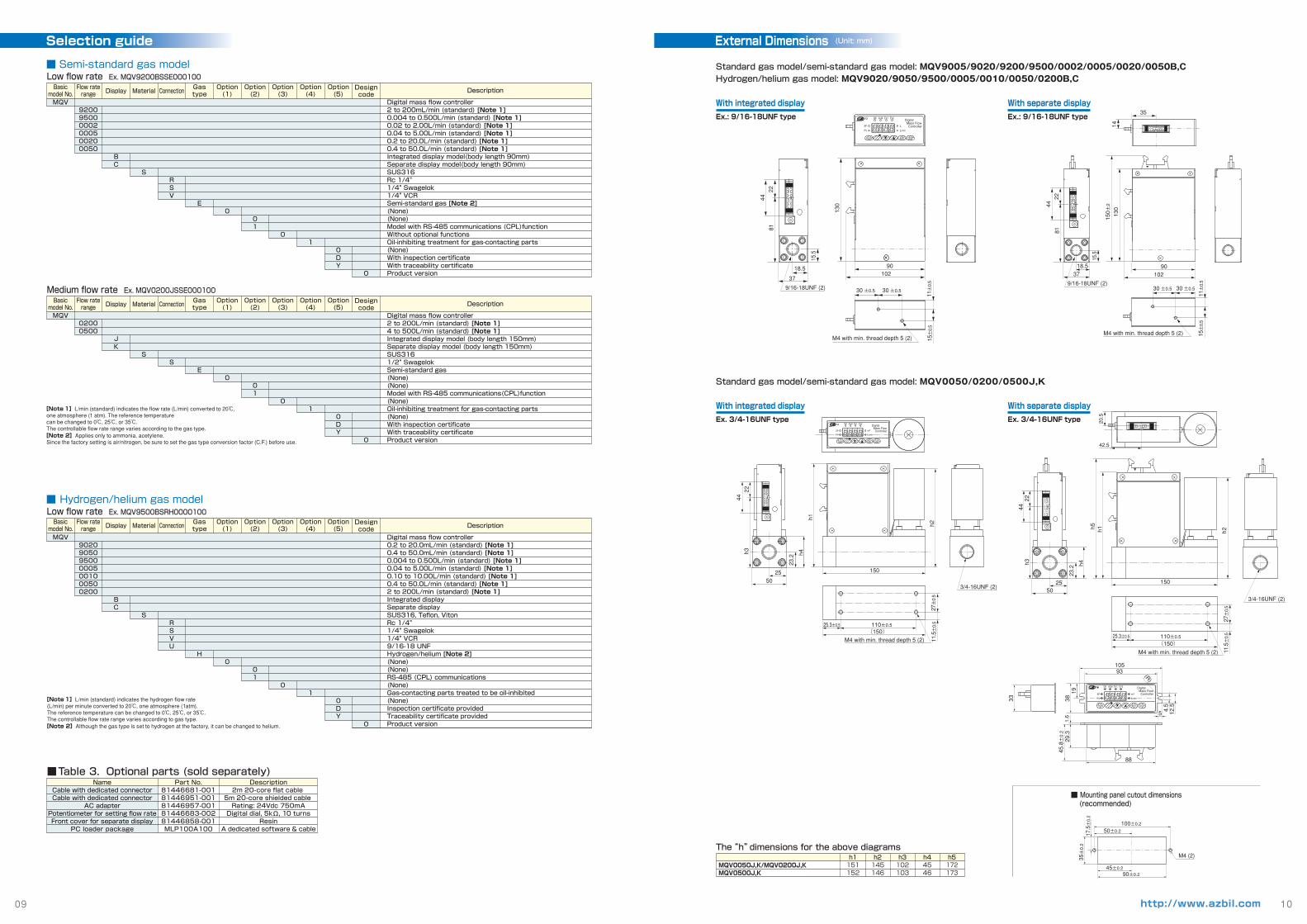
Standard gas model/semi-standard gas model: MQV9005/9020/9200/9500/0002/0005/0020/0050B,C Hydrogen/helium gas model: MQV9020/9050/9500/0005/0010/0050/0200B,C
Standard gas model/semi-standard gas model: MQV0050/0200/0500J,K
Selection guide External Dimensions (Unit: mm)
09 10http://www.azbil.com
MQV0050J,K/MQV0200J,KMQV0500J,K 152 146 103 46
151 145 102 45173172
h1 h2 h3 h4 h5
The “h” dimensions for the above diagrams
With integrated display
Ex. 3/4-16UNF type
With separate display
Ex. 3/4-16UNF type
With integrated display
Ex.: 9/16-18UNF type
With separate display
Ex.: 9/16-18UNF type
■ Mounting panel cutout dimensions (recommended)
OK
SP
PV
m3
Digital Mass Flow Controller L/min
ALM EV1 EV2Micro Flow
RUN ENT▲
▼ DISP▲
88
45.8±0.2
29.3
1.6
3833
10593
5 4.5
12.5
35±0.2
17.5±0.2
100±0.2
90±0.2
M4 (2)
19
50±0.2
45±0.2
(R)
37
9/16-18UNF (2)
4422
81
18.5
15.5
30 ±0.5 30 ±0.5
11±0.5
15±0.5
M4 with min. thread depth 5 (2)
130
90102
OK
SP
PV
L
Digital Mass Flow Controller L/min
ALM EV1 EV2Micro Flow
RUN ENT▲
▼ DISP▲
3/4-16UNF (2)
h1
h2
150
(150)110±0.525.3±0.5
27±0.5
11.5±0.5
M4 with min. thread depth 5 (2)
2550
4422
h3
OK
SP
PV
m3
Digital Mass Flow Controller L/min
ALM EV1 EV2Micro Flow
RUN ENT▲
▼ DISP▲
23.2 h4
3/4-16UNF (2)
20.5
h5 h1 h2
150
42.5
(150)110±0.525.3±0.5
27±0.5
11.5±0.5
M4 with min. thread depth 5 (2)
2550
23.2
4422
h3 h4
37
9/16-18UNF (2)
4422
81
18.5
15.5
130
150±2
90102
35
14
30 ±0.5 30 ±0.5
11±0.5
15±0.5
M4 with min. thread depth 5 (2)
■ Hydrogen/helium gas modelLow flow rate Ex. MQV9500BSRH0000100
■ Semi-standard gas modelLow flow rate Ex. MQV9200BSSE000100
Medium flow rate Ex. MQV0200JSSE000100
■Table 3. Optional parts (sold separately)
[Note 1]L/min (standard) indicates the flow rate (L/min) converted to 20℃, one atmosphere (1 atm). The reference temperature can be changed to 0℃, 25℃, or 35℃.The controllable flow rate range varies according to the gas type.[Note 2]Applies only to ammonia, acetylene.Since the factory setting is air/nitrogen, be sure to set the gas type conversion factor (C.F.) before use.
[Note 1]L/min (standard) indicates the hydrogen flow rate(L/min) per minute converted to 20℃, one atmosphere (1 atm).The reference temperature can be changed to 0℃, 25℃, or 35℃.The controllable flow rate range varies according to gas type.[Note 2]Although the gas type is set to hydrogen at the factory, it can be changed to helium.
Basicmodel No.
Flow raterange Display Material Connection
Gastype
Option(1)
Option(2)
Option(3)
Option(4)
Option(5)
Designcode
Basicmodel No.
Flow raterange Display Material Connection
Gastype
Option(1)
Option(2)
Option(3)
Option(4)
Option(5)
Designcode
Basicmodel No.
Flow raterange Display Material Connection
Gastype
Option(1)
Option(2)
Option(3)
Option(4)
Option(5)
Designcode
Description
Digital mass flow controller0.2 to 20.0mL/min (standard) [Note 1]0.4 to 50.0mL/min (standard) [Note 1]0.004 to 0.500L/min (standard) [Note 1]0.04 to 5.00L/min (standard) [Note 1]0.10 to 10.00L/min (standard) [Note 1]0.4 to 50.0L/min (standard) [Note 1]2 to 200L/min (standard) [Note 1]Integrated displaySeparate displaySUS316, Teflon, VitonRc 1/4" 1/4" Swagelok1/4" VCR9/16-18 UNFHydrogen/helium [Note 2](None)(None)RS-485 (CPL) communications(None)Gas-contacting parts treated to be oil-inhibited(None)Inspection certificate providedTraceability certificate providedProduct version
MQV9020905095000005001000500200
BC
SRSVU
H0
01
01
0DY
0
NameCable with dedicated connectorCable with dedicated connector
AC adapterPotentiometer for setting flow rateFront cover for separate display
PC loader package
Part No.81446681-00181446951-00181446957-00181446683-00281446858-001MLP100A100
Description2m 20-core flat cable
5m 20-core shielded cable Rating: 24Vdc 750mADigital dial, 5kΩ, 10 turns
ResinA dedicated software & cable
MQV920095000002000500200050
BC
S
VSR
E0
01
01
0DY
0
MQV02000500
JK
SS
E0
01
01
0DY
0
Description
Digital mass flow controller2 to 200mL/min (standard) [Note 1]0.004 to 0.500L/min (standard) [Note 1]0.02 to 2.00L/min (standard) [Note 1]0.04 to 5.00L/min (standard) [Note 1]0.2 to 20.0L/min (standard) [Note 1]0.4 to 50.0L/min (standard) [Note 1]Integrated display model(body length 90mm)Separate display model(body length 90mm)SUS316Rc 1/4" 1/4" Swagelok1/4" VCRSemi-standard gas [Note 2](None)(None)Model with RS-485 communications (CPL)functionWithout optional functionsOil-inhibiting treatment for gas-contacting parts(None)With inspection certificateWith traceability certificateProduct version
Description
Digital mass flow controller2 to 200L/min (standard) [Note 1]4 to 500L/min (standard) [Note 1]Integrated display model (body length 150mm) Separate display model (body length 150mm)SUS3161/2" SwagelokSemi-standard gas(None)(None)Model with RS-485 communications(CPL)function(None)Oil-inhibiting treatment for gas-contacting parts(None)With inspection certificateWith traceability certificateProduct version