washington state energy code, appendix chapters
TRANSCRIPT
2015 Washington State Energy Code AE-1
Chapter 51-11C WAC
WASHINGTON STATE ENERGY CODE, APPENDIX CHAPTERS
TABLE OF CONTENTS
Appendix A Default Heat Loss Coefficients ............................... AE-3
A101 General ............................................. AE-3
A101.1 Scope ......................................... AE-3
A101.2 Description ................................ AE-3
A101.3 Air Films ................................... AE-3
A101.4 R-Value of Compressed
Insulation ....................................... AE-3
A101.5 Building Materials ..................... AE-3
A102 Ceilings ............................................. AE-5
A102.1 Default U-Factors
for Ceilings .................................... AE-5
A102.2 Component Description ............. AE-5
A102.2.1 Vented Attic ......................... AE-5
A102.2.2 Vaulted Ceiling .................... AE-5
A102.2.3 Roof Decks .......................... AE-5
A102.2.4 Metal Truss Framing............ AE-5
A102.2.5 Metal Building Roof ............ AE-7
A102.2.6 Insulation Entirely Above
Roof Deck .................................. AE-8
A103 Above Grade Walls ....................... AE-12
A103.1 General .................................... AE-12
A103.2 Framing Description ................ AE-12
A103.3 Component Description ........... AE-12
A103.3.1 Single Stud Wall ................ AE-12
A103.3.2 Strap Wall .......................... AE-17
A103.3.3 Double Stud Wall .............. AE-17
A103.3.4 Log Wall ............................ AE-17
A103.3.5 Stress Skin Panel ............... AE-17
A103.3.6 Metal Stud Walls ............... AE-17
A103.3.7 Concrete and
Masonry Walls ......................... AE-17
A104 Below Grade Walls and Slabs ...... AE-28
A104.1 General .................................... AE-28
A104.2 Component Description ........... AE-28
A104.3 Insulation Description ............. AE-29
A105 Floors Over
Unconditioned Space ................ AE-29
A105.1 General .................................... AE-29
A105.2 Crawlspace Description ........... AE-31
A105.3 Construction Description ......... AE-31
A106 On-Grade Slab Floors .................. AE-31
A106.1 General .................................... AE-31
A106.2 Component Description ........... AE-32
A106.3 Insulation Description .............. AE-32
A107 Default U-Factors for Doors ......... AE-32
A107.1 Doors Without NFRC
Certification ................................. AE-32
A108 Air Infiltration .............................. AE-36
A108.1 General .................................... AE-36
Appendix B Default Internal Load Values and Schedules ...................... AE-37
B101 General ............................................ AE-37
B102 Default Tables of
Internal Loads .............................. AE-37
B103 Default Schedules ............................ AE-38
Appendix C Exterior Design Conditions ............................. AE-49
Appendix D Renewable Energy ............... AE-51
AE-2 2015 Washington State Energy Code
Appendix A
DEFAULT HEAT LOSS COEFFICIENTS
SECTION A101 GENERAL REQUIREMENTS
A101.1 Scope. The following defaults shall apply to
Chapter 4 of both the (RE) and (CE) sections of the
WSEC. This chapter includes tables of seasonal
average heat loss coefficients for specified nominal
insulation.
A101.2 Description. These coefficients were
developed primarily from data and procedures from
the ASHRAE Fundamentals Handbook.
Coefficients not contained in this chapter may be
computed using the procedures listed in this reference
if the assumptions in the following sections are used,
along with data from the sources referenced above.
A101.3 Air films. Default R-values used for air
films shall be as follows:
R-Value Condition
0.17 All exterior surfaces
0.61 Interior horizontal surfaces,
heat flow up
0.92 Interior horizontal surfaces,
heat flow down
0.68 Interior vertical surfaces
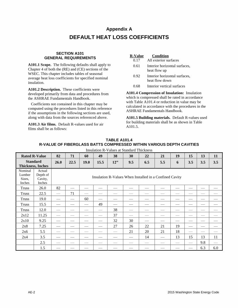
A101.4 Compression of Insulation: Insulation
which is compressed shall be rated in accordance
with Table A101.4 or reduction in value may be
calculated in accordance with the procedures in the
ASHRAE Fundamentals Handbook.
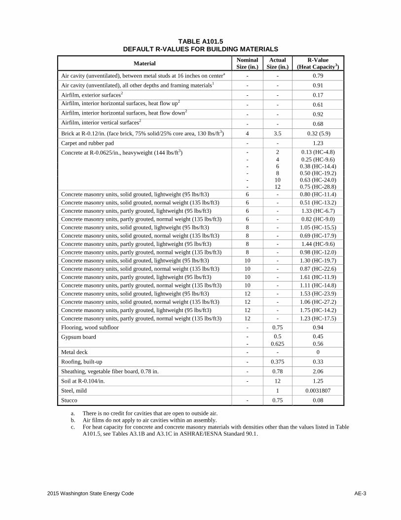
A101.5 Building materials. Default R-values used
for building materials shall be as shown in Table
A101.5.
TABLE A101.4 R-VALUE OF FIBERGLASS BATTS COMPRESSED WITHIN VARIOUS DEPTH CAVITIES
Insulation R-Values at Standard Thickness
Rated R-Value 82 71 60 49 38 30 22 21 19 15 13 11
Standard
Thickness, Inches 26.0 22.5 19.0 15.5 12” 9.5 6.5 5.5 6 3.5 3.5 3.5
Nominal
Lumber
Sizes,
Inches
Actual
Depth of
Cavity,
Inches
Insulation R-Values When Installed in a Confined Cavity
Truss 26.0 82 — — — — — — — — — — —
Truss 22.5 — 71 — — — — — — — — — —
Truss 19.0 — — 60 — — — — — — — — —
Truss 15.5 — — — 49 — — — — — — — —
Truss 12.0 — — — — 38 — — — — — — —
2x12 11.25 — — — — 37 — — — — — — —
2x10 9.25 — — — — 32 30 — — — — — —
2x8 7.25 — — — — 27 26 22 21 19 — — —
2x6 5.5 — — — — — 21 20 21 18 — — —
2x4 3.5 — — — — — — 14 — 13 15 13 11
2.5 — — — — — — — — — — 9.8 —
1.5 — — — — — — — — — — 6.3 6.0
2015 Washington State Energy Code AE-3
TABLE A101.5 DEFAULT R-VALUES FOR BUILDING MATERIALS
Material Nominal
Size (in.)
Actual
Size (in.)
R-Value
(Heat Capacity3)
Air cavity (unventilated), between metal studs at 16 inches on centera - - 0.79
Air cavity (unventilated), all other depths and framing materials1 - - 0.91
Airfilm, exterior surfaces2 - - 0.17
Airfilm, interior horizontal surfaces, heat flow up2 - - 0.61
Airfilm, interior horizontal surfaces, heat flow down2 - - 0.92
Airfilm, interior vertical surfaces2 - - 0.68
Brick at R-0.12/in. (face brick, 75% solid/25% core area, 130 lbs/ft3) 4 3.5 0.32 (5.9)
Carpet and rubber pad - - 1.23
Concrete at R-0.0625/in., heavyweight (144 lbs/ft3) - 2 0.13 (HC-4.8)
- 4 0.25 (HC-9.6)
- 6 0.38 (HC-14.4)
- 8 0.50 (HC-19.2)
- 10 0.63 (HC-24.0)
- 12 0.75 (HC-28.8)
Concrete masonry units, solid grouted, lightweight (95 lbs/ft3) 6 - 0.80 (HC-11.4)
Concrete masonry units, solid grouted, normal weight (135 lbs/ft3) 6 - 0.51 (HC-13.2)
Concrete masonry units, partly grouted, lightweight (95 lbs/ft3) 6 - 1.33 (HC-6.7)
Concrete masonry units, partly grouted, normal weight (135 lbs/ft3) 6 - 0.82 (HC-9.0)
Concrete masonry units, solid grouted, lightweight (95 lbs/ft3) 8 - 1.05 (HC-15.5)
Concrete masonry units, solid grouted, normal weight (135 lbs/ft3) 8 - 0.69 (HC-17.9)
Concrete masonry units, partly grouted, lightweight (95 lbs/ft3) 8 - 1.44 (HC-9.6)
Concrete masonry units, partly grouted, normal weight (135 lbs/ft3) 8 - 0.98 (HC-12.0)
Concrete masonry units, solid grouted, lightweight (95 lbs/ft3) 10 - 1.30 (HC-19.7)
Concrete masonry units, solid grouted, normal weight (135 lbs/ft3) 10 - 0.87 (HC-22.6)
Concrete masonry units, partly grouted, lightweight (95 lbs/ft3) 10 - 1.61 (HC-11.9)
Concrete masonry units, partly grouted, normal weight (135 lbs/ft3) 10 - 1.11 (HC-14.8)
Concrete masonry units, solid grouted, lightweight (95 lbs/ft3) 12 - 1.53 (HC-23.9)
Concrete masonry units, solid grouted, normal weight (135 lbs/ft3) 12 - 1.06 (HC-27.2)
Concrete masonry units, partly grouted, lightweight (95 lbs/ft3) 12 - 1.75 (HC-14.2)
Concrete masonry units, partly grouted, normal weight (135 lbs/ft3) 12 - 1.23 (HC-17.5)
Flooring, wood subfloor - 0.75 0.94
Gypsum board - 0.5 0.45
- 0.625 0.56
Metal deck - - 0
Roofing, built-up - 0.375 0.33
Sheathing, vegetable fiber board, 0.78 in. - 0.78 2.06
Soil at R-0.104/in. - 12 1.25
Steel, mild 1 0.0031807
Stucco - 0.75 0.08
a. There is no credit for cavities that are open to outside air.
b. Air films do not apply to air cavities within an assembly.
c. For heat capacity for concrete and concrete masonry materials with densities other than the values listed in Table
A101.5, see Tables A3.1B and A3.1C in ASHRAE/IESNA Standard 90.1.
AE-4 2015 Washington State Energy Code
SECTION A102 CEILINGS
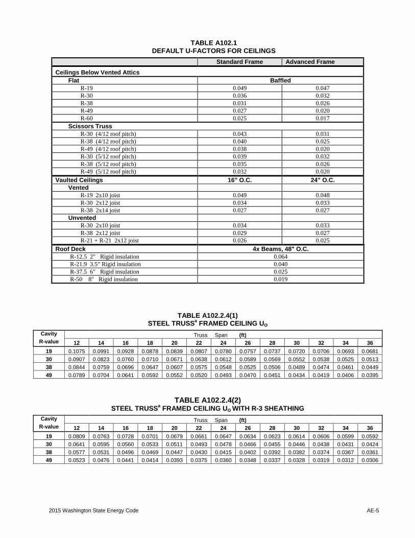
A102.1 General. Table A102.1 lists heat loss
coefficients for the opaque portion of exterior
ceilings below vented attics, vaulted ceilings and roof
decks in units of Btu/h × ft2 × °F of ceiling.
They are derived from procedures listed in the
ASHRAE Fundamentals Handbook. Ceiling U-
factors are modified for the buffering effect of the
attic, assuming an indoor temperature of 65°F and an
outdoor temperature of 45°F.
A102.1.1 Metal framed ceilings. The nominal R-
values in Table A103.3.6.2: Effective R-Values
for Metal Framing and Cavity Only may be used
for purposes of calculating metal framed ceiling
section U-factors in lieu of the ASHRAE zone
calculation method as provided in Chapter 27 of
the ASHRAE Fundamentals Handbook.
Metal building roofs have a different construction
and are addressed in Table A102.2.5.
A102.2 Component description. The four types of
ceilings are characterized as follows:
A102.2.1 Ceilings below a vented attic. Attic
insulation is assumed to be blown-in, loose-fill
fiberglass with a K-value of 2.6 h × ft2 •× °F/Btu
per inch. Full bag count for specified R-value is
assumed in all cases. Ceiling dimensions for flat
ceiling calculations are 45 by 30 feet, with a gabled
roof having a 4/12 pitch. The attic is assumed to
vent naturally at the rate of 3 air changes per hour
through soffit and ridge vents. A void fraction of
0.002 is assumed for all attics with insulation
baffles. Standard-framed, unbaffled attics assume
a void fraction of 0.008.
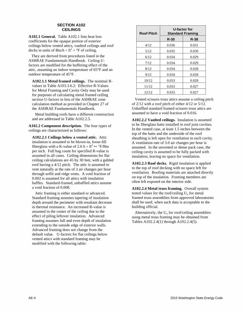
Attic framing is either standard or advanced.
Standard framing assumes tapering of insulation
depth around the perimeter with resultant decrease
in thermal resistance. An increased R-value is
assumed in the center of the ceiling due to the
effect of piling leftover insulation. Advanced
framing assumes full and even depth of insulation
extending to the outside edge of exterior walls.
Advanced framing does not change from the
default value. U-factors for flat ceilings below
vented attics with standard framing may be
modified with the following table:
Roof Pitch U-factor for
Standard Framing
R-30 R-38
4/12 0.036 0.031
5/12 0.035 0.030
6/12 0.034 0.029
7/12 0.034 0.029
8/12 0.034 0.028
9/12 0.034 0.028
10/12 0.033 0.028
11/12 0.033 0.027
12/12 0.033 0.027
Vented scissors truss attics assume a ceiling pitch
of 2/12 with a roof pitch of either 4/12 or 5/12.
Unbaffled standard framed scissors truss attics are
assumed to have a void fraction of 0.016.
A102.2.2 Vaulted ceilings. Insulation is assumed
to be fiberglass batts installed in roof joist cavities.
In the vented case, at least 1.5 inches between the
top of the batts and the underside of the roof
sheathing is left open for ventilation in each cavity.
A ventilation rate of 3.0 air changes per hour is
assumed. In the unvented or dense pack case, the
ceiling cavity is assumed to be fully packed with
insulation, leaving no space for ventilation.
A102.2.3 Roof decks. Rigid insulation is applied
to the top of roof decking with no space left for
ventilation. Roofing materials are attached directly
on top of the insulation. Framing members are
often left exposed on the interior side.
A102.2.4 Metal truss framing. Overall system
tested values for the roof/ceiling Uo for metal
framed truss assemblies from approved laboratories
shall be used, when such data is acceptable to the
building official.
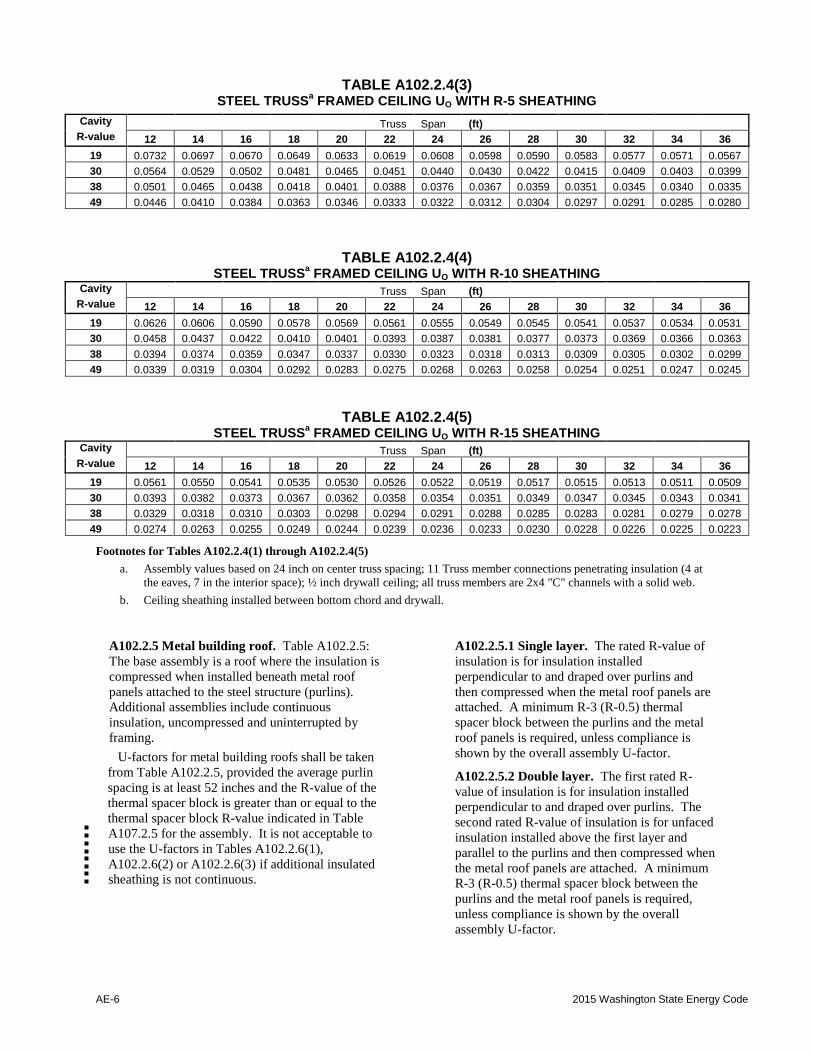
Alternatively, the Uo for roof/ceiling assemblies
using metal truss framing may be obtained from
Tables A102.2.4(1) through A102.2.4(5).
2015 Washington State Energy Code AE-5
TABLE A102.1 DEFAULT U-FACTORS FOR CEILINGS
Standard Frame Advanced Frame
Ceilings Below Vented Attics
Flat Baffled
R-19 0.049 0.047
R-30 0.036 0.032
R-38 0.031 0.026
R-49 0.027 0.020
R-60 0.025 0.017
Scissors Truss
R-30 (4/12 roof pitch) 0.043 0.031
R-38 (4/12 roof pitch) 0.040 0.025
R-49 (4/12 roof pitch) 0.038 0.020
R-30 (5/12 roof pitch) 0.039 0.032
R-38 (5/12 roof pitch) 0.035 0.026
R-49 (5/12 roof pitch) 0.032 0.020
Vaulted Ceilings 16" O.C. 24" O.C.
Vented
R-19 2x10 joist 0.049 0.048
R-30 2x12 joist 0.034 0.033
R-38 2x14 joist 0.027 0.027
Unvented
R-30 2x10 joist 0.034 0.033
R-38 2x12 joist 0.029 0.027
R-21 + R-21 2x12 joist 0.026 0.025
Roof Deck 4x Beams, 48" O.C.
R-12.5 2" Rigid insulation 0.064
R-21.9 3.5" Rigid insulation 0.040
R-37.5 6" Rigid insulation 0.025
R-50 8" Rigid insulation 0.019
TABLE A102.2.4(1) STEEL TRUSS
a FRAMED CEILING UO
Cavity Truss Span (ft)
R-value 12 14 16 18 20 22 24 26 28 30 32 34 36
19 0.1075 0.0991 0.0928 0.0878 0.0839 0.0807 0.0780 0.0757 0.0737 0.0720 0.0706 0.0693 0.0681
30 0.0907 0.0823 0.0760 0.0710 0.0671 0.0638 0.0612 0.0589 0.0569 0.0552 0.0538 0.0525 0.0513
38 0.0844 0.0759 0.0696 0.0647 0.0607 0.0575 0.0548 0.0525 0.0506 0.0489 0.0474 0.0461 0.0449
49 0.0789 0.0704 0.0641 0.0592 0.0552 0.0520 0.0493 0.0470 0.0451 0.0434 0.0419 0.0406 0.0395
TABLE A102.2.4(2) STEEL TRUSS
a FRAMED CEILING UO WITH R-3 SHEATHING
Cavity Truss Span (ft)
R-value 12 14 16 18 20 22 24 26 28 30 32 34 36
19 0.0809 0.0763 0.0728 0.0701 0.0679 0.0661 0.0647 0.0634 0.0623 0.0614 0.0606 0.0599 0.0592
30 0.0641 0.0595 0.0560 0.0533 0.0511 0.0493 0.0478 0.0466 0.0455 0.0446 0.0438 0.0431 0.0424
38 0.0577 0.0531 0.0496 0.0469 0.0447 0.0430 0.0415 0.0402 0.0392 0.0382 0.0374 0.0367 0.0361
49 0.0523 0.0476 0.0441 0.0414 0.0393 0.0375 0.0360 0.0348 0.0337 0.0328 0.0319 0.0312 0.0306
AE-6 2015 Washington State Energy Code
TABLE A102.2.4(3) STEEL TRUSS
a FRAMED CEILING UO WITH R-5 SHEATHING
Cavity Truss Span (ft)
R-value 12 14 16 18 20 22 24 26 28 30 32 34 36
19 0.0732 0.0697 0.0670 0.0649 0.0633 0.0619 0.0608 0.0598 0.0590 0.0583 0.0577 0.0571 0.0567
30 0.0564 0.0529 0.0502 0.0481 0.0465 0.0451 0.0440 0.0430 0.0422 0.0415 0.0409 0.0403 0.0399
38 0.0501 0.0465 0.0438 0.0418 0.0401 0.0388 0.0376 0.0367 0.0359 0.0351 0.0345 0.0340 0.0335
49 0.0446 0.0410 0.0384 0.0363 0.0346 0.0333 0.0322 0.0312 0.0304 0.0297 0.0291 0.0285 0.0280
TABLE A102.2.4(4) STEEL TRUSS
a FRAMED CEILING UO WITH R-10 SHEATHING
Cavity Truss Span (ft)
R-value 12 14 16 18 20 22 24 26 28 30 32 34 36
19 0.0626 0.0606 0.0590 0.0578 0.0569 0.0561 0.0555 0.0549 0.0545 0.0541 0.0537 0.0534 0.0531
30 0.0458 0.0437 0.0422 0.0410 0.0401 0.0393 0.0387 0.0381 0.0377 0.0373 0.0369 0.0366 0.0363
38 0.0394 0.0374 0.0359 0.0347 0.0337 0.0330 0.0323 0.0318 0.0313 0.0309 0.0305 0.0302 0.0299
49 0.0339 0.0319 0.0304 0.0292 0.0283 0.0275 0.0268 0.0263 0.0258 0.0254 0.0251 0.0247 0.0245
TABLE A102.2.4(5) STEEL TRUSS
a FRAMED CEILING UO WITH R-15 SHEATHING
Cavity Truss Span (ft)
R-value 12 14 16 18 20 22 24 26 28 30 32 34 36
19 0.0561 0.0550 0.0541 0.0535 0.0530 0.0526 0.0522 0.0519 0.0517 0.0515 0.0513 0.0511 0.0509
30 0.0393 0.0382 0.0373 0.0367 0.0362 0.0358 0.0354 0.0351 0.0349 0.0347 0.0345 0.0343 0.0341
38 0.0329 0.0318 0.0310 0.0303 0.0298 0.0294 0.0291 0.0288 0.0285 0.0283 0.0281 0.0279 0.0278
49 0.0274 0.0263 0.0255 0.0249 0.0244 0.0239 0.0236 0.0233 0.0230 0.0228 0.0226 0.0225 0.0223
Footnotes for Tables A102.2.4(1) through A102.2.4(5)
a. Assembly values based on 24 inch on center truss spacing; 11 Truss member connections penetrating insulation (4 at
the eaves, 7 in the interior space); ½ inch drywall ceiling; all truss members are 2x4 "C" channels with a solid web.
b. Ceiling sheathing installed between bottom chord and drywall.
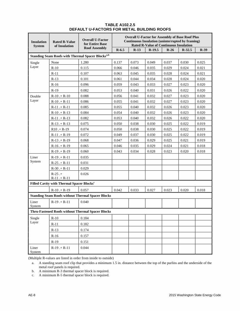
A102.2.5 Metal building roof. Table A102.2.5:
The base assembly is a roof where the insulation is
compressed when installed beneath metal roof
panels attached to the steel structure (purlins).
Additional assemblies include continuous
insulation, uncompressed and uninterrupted by
framing.
U-factors for metal building roofs shall be taken
from Table A102.2.5, provided the average purlin
spacing is at least 52 inches and the R-value of the
thermal spacer block is greater than or equal to the
thermal spacer block R-value indicated in Table
A107.2.5 for the assembly. It is not acceptable to
use the U-factors in Tables A102.2.6(1),
A102.2.6(2) or A102.2.6(3) if additional insulated
sheathing is not continuous.
A102.2.5.1 Single layer. The rated R-value of
insulation is for insulation installed
perpendicular to and draped over purlins and
then compressed when the metal roof panels are
attached. A minimum R-3 (R-0.5) thermal
spacer block between the purlins and the metal
roof panels is required, unless compliance is
shown by the overall assembly U-factor.
A102.2.5.2 Double layer. The first rated R-
value of insulation is for insulation installed
perpendicular to and draped over purlins. The
second rated R-value of insulation is for unfaced
insulation installed above the first layer and
parallel to the purlins and then compressed when
the metal roof panels are attached. A minimum
R-3 (R-0.5) thermal spacer block between the
purlins and the metal roof panels is required,
unless compliance is shown by the overall
assembly U-factor.

2015 Washington State Energy Code AE-7
A102.2.5.3 Continuous insulation. For
continuous insulation (e.g., insulation boards or
blankets), it is assumed that the insulation is
installed below the purlins and is uninterrupted
by framing members. Insulation exposed to the
conditioned space or semi-heated space shall
have a facing, and all insulation seams shall be
continuously sealed to provide a continuous air
barrier.
A102.2.5.4 Liner system (Ls). A continuous
membrane is installed below the purlins and
uninterrupted by framing members.
Uncompressed, unfaced insulation rests on top of
the membrane between the purlins. For
multilayer installations, the last rated R-value of
insulation is for unfaced insulation draped over
purlins and then compressed when the metal roof
panels are attached. A minimum R-3 (R-0.5)
thermal spacer block between the purlins and the
metal roof panels is required, unless compliance
is shown by the overall assembly U-factor.
A102.2.5.5 Filled cavity. The first rated R-
value of insulation is for faced insulation
installed parallel to the purlins. The second rated
R-value of insulation is for unfaced insulation
installed above the first layer, parallel to and
between the purlins and compressed when the
metal roof panels are attached. The facer of the
first layer of insulation is of sufficient width to
be continuously sealed to the top flange of the
purlins and to accommodate the full thickness of
the second layer of insulation. A supporting
structure retains the bottom of the first layer at
the prescribed depth required for the full
thickness of the second layer of insulation being
installed above it. A minimum R-5 (R-0.9)
thermal spacer block between the purlins and the
metal roof panels is required, unless compliance
is shown by the overall assembly U-factor.
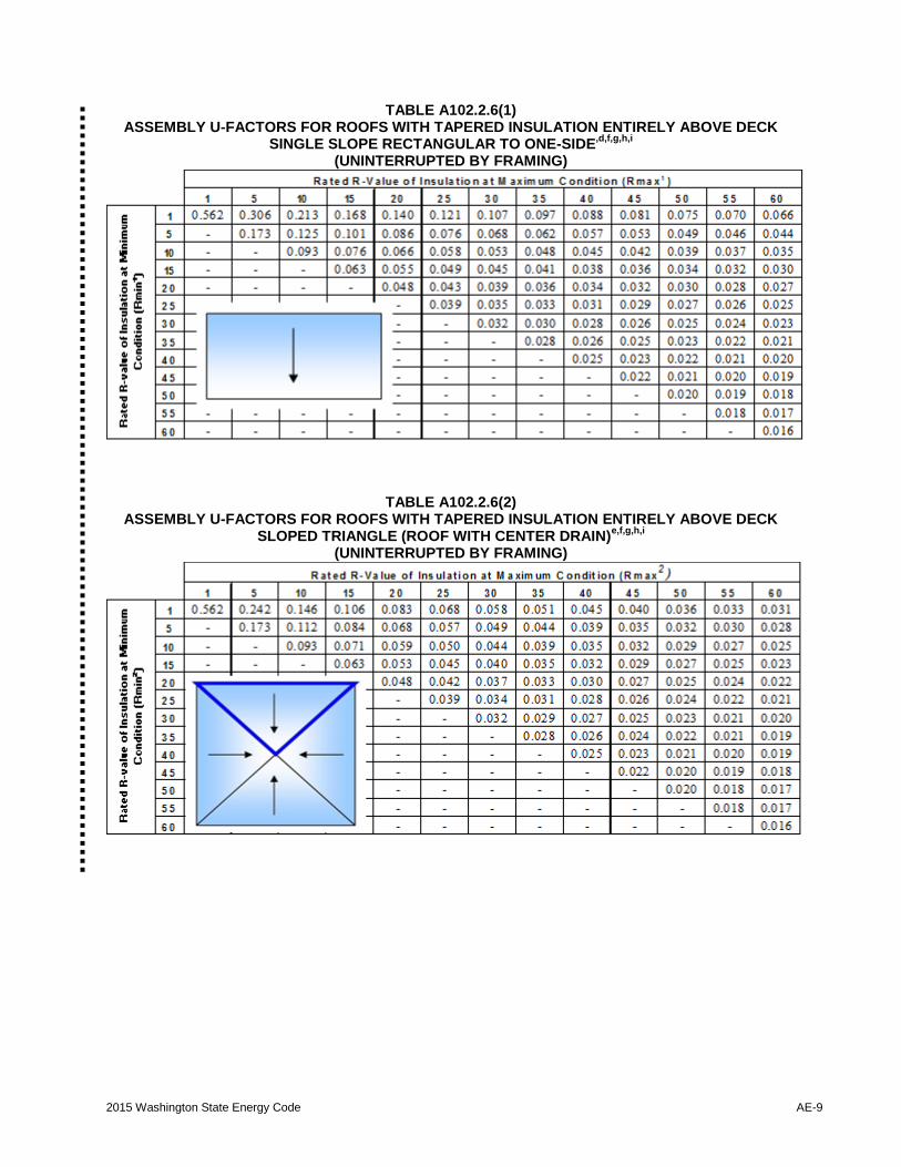
A102.2.6 Roofs with insulation entirely above
deck (uninterrupted by framing). Table
A102.2.6(1) through A102.2.6(3): The base
assembly is continuous insulation over a
structural deck. These tables indicate effective
U-factors for tapered roof insulation, sloped from
a maximum R-value (Rmax) at the peak of the
slope to a minimum R-value (Rmin) at the low
point of the slope. The rows of the tables
represent the rated R-value of the insulation at
the minimum conditions (except at roof drains)
and the columns of the table represent the rated
R-value of the insulation at the maximum
conditions. The slope of the tapered insulation
shall be no greater than 1/4 inch per foot.
AE-8 2015 Washington State Energy Code
TABLE A102.2.5 DEFAULT U-FACTORS FOR METAL BUILDING ROOFS
Insulation
System
Rated R-Value
of Insulation
Overall U-Factor
for Entire Base
Roof Assembly
Overall U-Factor for Assembly of Base Roof Plus
Continuous Insulation (uninterrupted by framing)
Rated R-Value of Continuous Insulation
R-6.5 R-13 R-19.5 R-26 R-32.5 R-39
Standing Seam Roofs with Thermal Spacer Blocksa,b
Single
Layer
None 1.280 0.137 0.073 0.049 0.037 0.030 0.025
R-10 0.115 0.066 0.046 0.035 0.029 0.024 0.021
R-11 0.107 0.063 0.045 0.035 0.028 0.024 0.021
R-13 0.101 0.061 0.044 0.034 0.028 0.024 0.020
R-16 0.096 0.059 0.043 0.033 0.027 0.023 0.020
R-19 0.082 0.053 0.040 0.031 0.026 0.022 0.020
Double
Layer
R-10 .+ R-10 0.088 0.056 0.041 0.032 0.027 0.023 0.020
R-10 .+ R-11 0.086 0.055 0.041 0.032 0.027 0.023 0.020
R-11 .+ R-11 0.085 0.055 0.040 0.032 0.026 0.023 0.020
R-10 .+ R-13 0.084 0.054 0.040 0.032 0.026 0.023 0.020
R-11 .+ R-13 0.082 0.053 0.040 0.032 0.026 0.022 0.020
R-13 .+ R-13 0.075 0.050 0.038 0.030 0.025 0.022 0.019
R10 .+ R-19 0.074 0.050 0.038 0.030 0.025 0.022 0.019
R-11 .+ R-19 0.072 0.049 0.037 0.030 0.025 0.022 0.019
R-13 .+ R-19 0.068 0.047 0.036 0.029 0.025 0.021 0.019
R-16 .+ R-19 0.065 0.046 0.035 0.029 0.024 0.021 0.018
R-19 .+ R-19 0.060 0.043 0.034 0.028 0.023 0.020 0.018
Liner
System
R-19 .+ R-11 0.035
R-25 .+ R-11 0.031
R-30 .+ R-11 0.029
R-25 .+
R-11 .+ R-11
0.026
Filled Cavity with Thermal Spacer Blocksc
R-10 .+ R-19 0.057 0.042 0.033 0.027 0.023 0.020 0.018
Standing Seam Roofs without Thermal Spacer Blocks
Liner
System
R-19 .+ R-11 0.040
Thru-Fastened Roofs without Thermal Spacer Blocks
Single
Layer
R-10 0.184
R-11 0.182
R-13 0.174
R-16 0.157
R-19 0.151
Liner
System
R-19 .+ R-11 0.044
(Multiple R-values are listed in order from inside to outside)
a. A standing seam roof clip that provides a minimum 1.5 in. distance between the top of the purlins and the underside of the
metal roof panels is required.
b. A minimum R-3 thermal spacer block is required.
c. A minimum R-5 thermal spacer block is required.
2015 Washington State Energy Code AE-9
TABLE A102.2.6(1) ASSEMBLY U-FACTORS FOR ROOFS WITH TAPERED INSULATION ENTIRELY ABOVE DECK
SINGLE SLOPE RECTANGULAR TO ONE-SIDE,d,f,g,h,i
(UNINTERRUPTED BY FRAMING)
TABLE A102.2.6(2) ASSEMBLY U-FACTORS FOR ROOFS WITH TAPERED INSULATION ENTIRELY ABOVE DECK
SLOPED TRIANGLE (ROOF WITH CENTER DRAIN)e,f,g,h,i
(UNINTERRUPTED BY FRAMING)
AE-10 2015 Washington State Energy Code
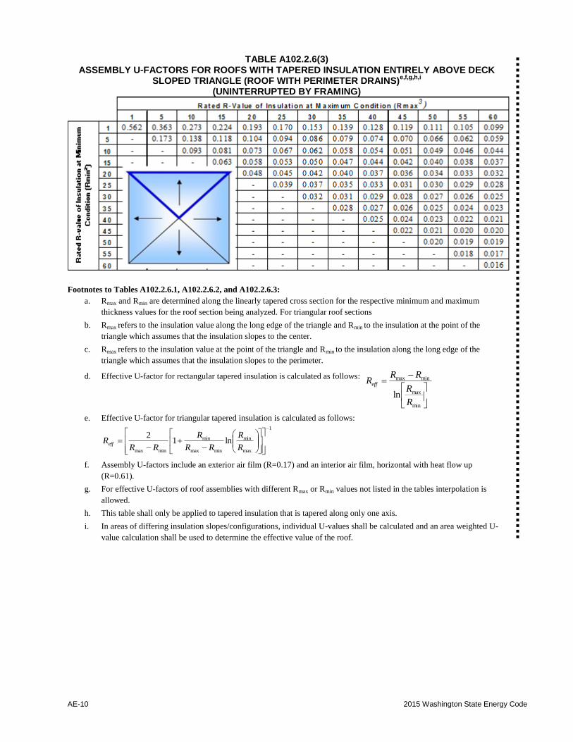
TABLE A102.2.6(3) ASSEMBLY U-FACTORS FOR ROOFS WITH TAPERED INSULATION ENTIRELY ABOVE DECK
SLOPED TRIANGLE (ROOF WITH PERIMETER DRAINS)e,f,g,h,i
(UNINTERRUPTED BY FRAMING)
Footnotes to Tables A102.2.6.1, A102.2.6.2, and A102.2.6.3:
a. Rmax and Rmin are determined along the linearly tapered cross section for the respective minimum and maximum
thickness values for the roof section being analyzed. For triangular roof sections
b. Rmax refers to the insulation value along the long edge of the triangle and Rmin to the insulation at the point of the
triangle which assumes that the insulation slopes to the center.
c. Rmax refers to the insulation value at the point of the triangle and Rmin to the insulation along the long edge of the
triangle which assumes that the insulation slopes to the perimeter.
d. Effective U-factor for rectangular tapered insulation is calculated as follows:
min
max
minmax
lnR
R
RRReff
e. Effective U-factor for triangular tapered insulation is calculated as follows: 1
max
min
minmax
min
minmax
ln12
R
R
RR
R
RRReff
f. Assembly U-factors include an exterior air film (R=0.17) and an interior air film, horizontal with heat flow up
(R=0.61).
g. For effective U-factors of roof assemblies with different Rmax or Rmin values not listed in the tables interpolation is
allowed.
h. This table shall only be applied to tapered insulation that is tapered along only one axis.
i. In areas of differing insulation slopes/configurations, individual U-values shall be calculated and an area weighted U-
value calculation shall be used to determine the effective value of the roof.

2015 Washington State Energy Code AE-11
SECTION A103 ABOVE GRADE WALLS
A103.1 General. The tables in this section list heat
loss coefficients for the opaque portion of above-
grade wood stud frame walls, metal stud frame walls
and concrete masonry walls (Btu/h × ft2 × °F). They
are derived from procedures listed in the ASHRAE
Fundamentals Handbook. For intermediate floor
slabs which penetrate the insulated wall, use the
concrete wall U-factors in Table A103.3.7.1(1).
Insulation is assumed to uniformly fill the entire
cavity and to be installed as per manufacturer's
directions. All walls are assumed to be finished on
the inside with 1/2 inch gypsum wallboard, and on
the outside with either beveled wood siding over 1/2
inch plywood sheathing or with 5/8 inch T1-11
siding. Insulated sheathing (either interior or
exterior) is assumed to cover the entire opaque wall
surface, except where modified in accordance with
footnote g to Table C402.1.3.
Metal building walls have a different construction
and are addressed in Table A103.3.6.3.
A103.2 Framing description. For wood stud frame
walls, three framing types are considered and defined
as follows:
A103.2.1 Standard. Studs framed on 16 inch
centers with double top plate and single bottom
plate. Corners use three studs and each opening is
framed using two studs. Headers consist of double
2x or single 4x material with an air space left
between the header and the exterior sheathing.
Interior partition wall/exterior wall intersections
use two studs in the exterior wall.
Standard framing weighting factors:
Studs and plates 0.19
Insulated cavity 0.77
Headers 0.04
A103.2.2 Intermediate. Studs framed on 16 inch
centers with double top plate and single bottom
plate. Corners use two studs or other means of
fully insulating corners, and each opening is
framed by two studs. Headers consist of double 2x
material with R-10 insulation. Interior partition
wall/exterior wall intersections are fully insulated
in the exterior wall.
Intermediate framing weighting factors:
Studs and plates 0.18
Insulated cavity 0.78
Headers 0.04
A103.2.3 Advanced. Studs framed on 24 inch
centers with double top plate and single bottom
plate. Corners use two studs or other means of
fully insulating corners, and one stud is used to
support each header. Headers consist of double 2x
material with R-10 insulation. Interior partition
wall/exterior wall intersections are fully insulated
in the exterior wall.
Advanced framing weighting factors:
Studs and plates 0.13
Insulated cavity 0.83
Headers 0.04
A103.3 Component description. Default
coefficients for the following types of walls are
listed: Single-stud walls, strap walls, double-stud
walls, log walls, stress-skin panels, metal stud walls,
and metal building walls.
A103.3.1 Single-stud wall. Tables A103.3.1(1)
through A103.3.1(8): Assumes either 2 x 4 or 2 x 6
studs framed on 16 or 24 inch centers. Headers are
solid for 2 x 4 walls and double 2x for 2 x 6 walls,
with either dead-air or rigid-board insulation in the
remaining space.

AE-12 2015 Washington State Energy Code
TABLE A103.3.1(1) 2 x 4 Single Wood Stud: R-11 Batt Siding Material/Framing Type
R-value of Foam Board
Lapped Wood T1-11
NOTE: STD ADV STD ADV
Nominal Batt R-value: 0 0.088 0.084 0.094 0.090
R-11 at 3.5 inch thickness 1 0.080 0.077 0.085 0.082
2 0.074 0.071 0.078 0.075
Installed Batt R-value: 3 0.069 0.066 0.072 0.070
R-11 in 3.5 inch cavity 4 0.064 0.062 0.067 0.065
5 0.060 0.058 0.063 0.061
6 0.056 0.055 0.059 0.057
7 0.053 0.052 0.055 0.054
8 0.051 0.049 0.052 0.051
9 0.048 0.047 0.050 0.049
10 0.046 0.045 0.047 0.046
11 0.044 0.043 0.045 0.044
12 0.042 0.041 0.043 0.042
TABLE A103.3.1(2) 2 x 4 Single Wood Stud: R-13 Batt Siding Material/Framing Type
R-value of Foam Board
Lapped Wood T1-11
NOTE: STD ADV STD ADV
Nominal Batt R-value: 0 0.082 0.078 0.088 0.083
R-13 at 3.63 inch thickness 1 0.075 0.072 0.080 0.076
2 0.069 0.066 0.073 0.070
Installed Batt R-value: 3 0.065 0.062 0.068 0.065
R-12.7 in 3.5 inch cavity 4 0.060 0.058 0.063 0.061
5 0.057 0.055 0.059 0.057
6 0.053 0.052 0.056 0.054
7 0.051 0.049 0.052 0.051
8 0.048 0.047 0.050 0.048
9 0.046 0.045 0.047 0.046
10 0.044 0.043 0.045 0.044
11 0.042 0.041 0.043 0.042
12 0.040 0.039 0.041 0.040
2015 Washington State Energy Code AE-13
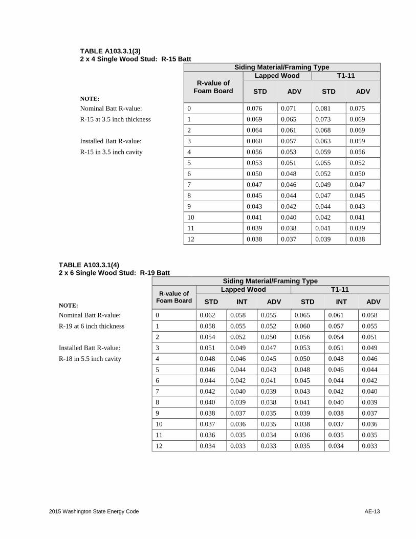
TABLE A103.3.1(3) 2 x 4 Single Wood Stud: R-15 Batt Siding Material/Framing Type
R-value of Foam Board
Lapped Wood T1-11
NOTE:
STD ADV STD ADV
Nominal Batt R-value: 0 0.076 0.071 0.081 0.075
R-15 at 3.5 inch thickness 1 0.069 0.065 0.073 0.069
2 0.064 0.061 0.068 0.069
Installed Batt R-value: 3 0.060 0.057 0.063 0.059
R-15 in 3.5 inch cavity 4 0.056 0.053 0.059 0.056
5 0.053 0.051 0.055 0.052
6 0.050 0.048 0.052 0.050
7 0.047 0.046 0.049 0.047
8 0.045 0.044 0.047 0.045
9 0.043 0.042 0.044 0.043
10 0.041 0.040 0.042 0.041
11 0.039 0.038 0.041 0.039
12 0.038 0.037 0.039 0.038
TABLE A103.3.1(4) 2 x 6 Single Wood Stud: R-19 Batt Siding Material/Framing Type
R-value of Foam Board
Lapped Wood T1-11
NOTE: STD INT ADV STD INT ADV
Nominal Batt R-value: 0 0.062 0.058 0.055 0.065 0.061 0.058
R-19 at 6 inch thickness 1 0.058 0.055 0.052 0.060 0.057 0.055
2 0.054 0.052 0.050 0.056 0.054 0.051
Installed Batt R-value: 3 0.051 0.049 0.047 0.053 0.051 0.049
R-18 in 5.5 inch cavity 4 0.048 0.046 0.045 0.050 0.048 0.046
5 0.046 0.044 0.043 0.048 0.046 0.044
6 0.044 0.042 0.041 0.045 0.044 0.042
7 0.042 0.040 0.039 0.043 0.042 0.040
8 0.040 0.039 0.038 0.041 0.040 0.039
9 0.038 0.037 0.035 0.039 0.038 0.037
10 0.037 0.036 0.035 0.038 0.037 0.036
11 0.036 0.035 0.034 0.036 0.035 0.035
12 0.034 0.033 0.033 0.035 0.034 0.033
AE-14 2015 Washington State Energy Code
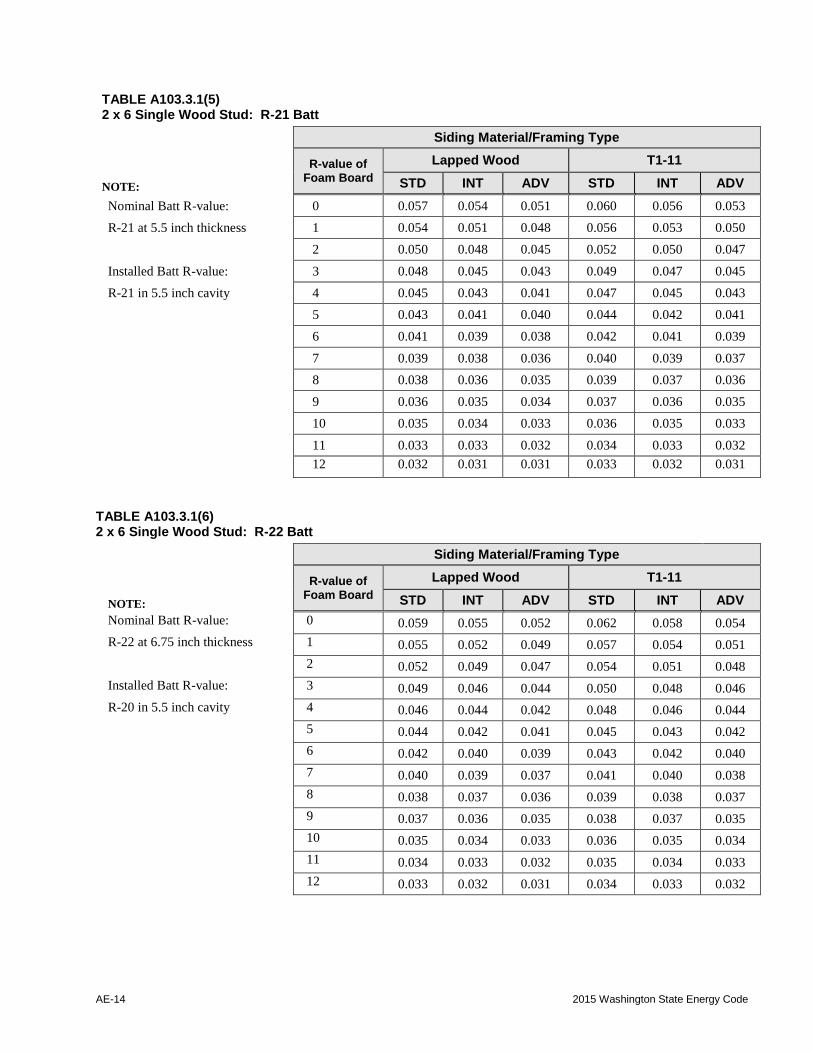
TABLE A103.3.1(5) 2 x 6 Single Wood Stud: R-21 Batt
Siding Material/Framing Type
R-value of Foam Board
Lapped Wood T1-11
NOTE: STD INT ADV STD INT ADV
Nominal Batt R-value: 0 0.057 0.054 0.051 0.060 0.056 0.053
R-21 at 5.5 inch thickness 1 0.054 0.051 0.048 0.056 0.053 0.050
2 0.050 0.048 0.045 0.052 0.050 0.047
Installed Batt R-value: 3 0.048 0.045 0.043 0.049 0.047 0.045
R-21 in 5.5 inch cavity 4 0.045 0.043 0.041 0.047 0.045 0.043
5 0.043 0.041 0.040 0.044 0.042 0.041
6 0.041 0.039 0.038 0.042 0.041 0.039
7 0.039 0.038 0.036 0.040 0.039 0.037
8 0.038 0.036 0.035 0.039 0.037 0.036
9 0.036 0.035 0.034 0.037 0.036 0.035
10 0.035 0.034 0.033 0.036 0.035 0.033
11 0.033 0.033 0.032 0.034 0.033 0.032
12 0.032 0.031 0.031 0.033 0.032 0.031
TABLE A103.3.1(6) 2 x 6 Single Wood Stud: R-22 Batt
Siding Material/Framing Type
R-value of Foam Board
Lapped Wood T1-11
NOTE: STD INT ADV STD INT ADV
Nominal Batt R-value: 0 0.059 0.055 0.052 0.062 0.058 0.054
R-22 at 6.75 inch thickness 1 0.055 0.052 0.049 0.057 0.054 0.051
2 0.052 0.049 0.047 0.054 0.051 0.048
Installed Batt R-value: 3 0.049 0.046 0.044 0.050 0.048 0.046
R-20 in 5.5 inch cavity 4 0.046 0.044 0.042 0.048 0.046 0.044
5 0.044 0.042 0.041 0.045 0.043 0.042
6 0.042 0.040 0.039 0.043 0.042 0.040
7 0.040 0.039 0.037 0.041 0.040 0.038
8 0.038 0.037 0.036 0.039 0.038 0.037
9 0.037 0.036 0.035 0.038 0.037 0.035
10 0.035 0.034 0.033 0.036 0.035 0.034
11 0.034 0.033 0.032 0.035 0.034 0.033
12 0.033 0.032 0.031 0.034 0.033 0.032
2015 Washington State Energy Code AE-15
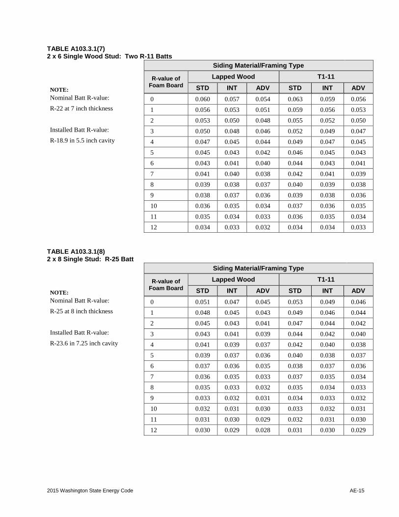
TABLE A103.3.1(7) 2 x 6 Single Wood Stud: Two R-11 Batts
Siding Material/Framing Type
R-value of Foam Board
Lapped Wood T1-11
NOTE: STD INT ADV STD INT ADV
Nominal Batt R-value: 0 0.060 0.057 0.054 0.063 0.059 0.056
R-22 at 7 inch thickness 1 0.056 0.053 0.051 0.059 0.056 0.053
2 0.053 0.050 0.048 0.055 0.052 0.050
Installed Batt R-value: 3 0.050 0.048 0.046 0.052 0.049 0.047
R-18.9 in 5.5 inch cavity 4 0.047 0.045 0.044 0.049 0.047 0.045
5 0.045 0.043 0.042 0.046 0.045 0.043
6 0.043 0.041 0.040 0.044 0.043 0.041
7 0.041 0.040 0.038 0.042 0.041 0.039
8 0.039 0.038 0.037 0.040 0.039 0.038
9 0.038 0.037 0.036 0.039 0.038 0.036
10 0.036 0.035 0.034 0.037 0.036 0.035
11 0.035 0.034 0.033 0.036 0.035 0.034
12 0.034 0.033 0.032 0.034 0.034 0.033
TABLE A103.3.1(8) 2 x 8 Single Stud: R-25 Batt
Siding Material/Framing Type
R-value of Foam Board
Lapped Wood T1-11
NOTE: STD INT ADV STD INT ADV
Nominal Batt R-value: 0 0.051 0.047 0.045 0.053 0.049 0.046
R-25 at 8 inch thickness 1 0.048 0.045 0.043 0.049 0.046 0.044
2 0.045 0.043 0.041 0.047 0.044 0.042
Installed Batt R-value: 3 0.043 0.041 0.039 0.044 0.042 0.040
R-23.6 in 7.25 inch cavity 4 0.041 0.039 0.037 0.042 0.040 0.038
5 0.039 0.037 0.036 0.040 0.038 0.037
6 0.037 0.036 0.035 0.038 0.037 0.036
7 0.036 0.035 0.033 0.037 0.035 0.034
8 0.035 0.033 0.032 0.035 0.034 0.033
9 0.033 0.032 0.031 0.034 0.033 0.032
10 0.032 0.031 0.030 0.033 0.032 0.031
11 0.031 0.030 0.029 0.032 0.031 0.030
12 0.030 0.029 0.028 0.031 0.030 0.029
AE-16 2015 Washington State Energy Code
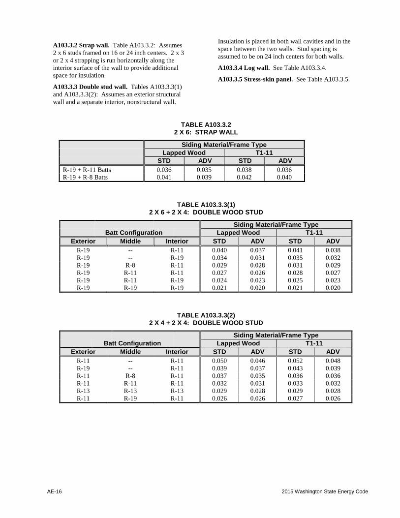
A103.3.2 Strap wall. Table A103.3.2: Assumes
2 x 6 studs framed on 16 or 24 inch centers. 2 x 3
or 2 x 4 strapping is run horizontally along the
interior surface of the wall to provide additional
space for insulation.
A103.3.3 Double stud wall. Tables A103.3.3(1)
and A103.3.3(2): Assumes an exterior structural
wall and a separate interior, nonstructural wall.
Insulation is placed in both wall cavities and in the
space between the two walls. Stud spacing is
assumed to be on 24 inch centers for both walls.
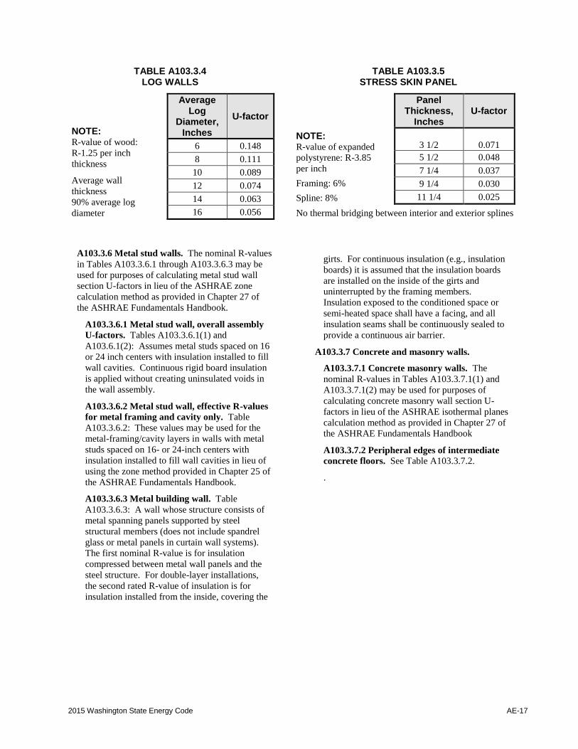
A103.3.4 Log wall. See Table A103.3.4.
A103.3.5 Stress-skin panel. See Table A103.3.5.
TABLE A103.3.2 2 X 6: STRAP WALL
Siding Material/Frame Type
Lapped Wood T1-11
STD ADV STD ADV
R-19 + R-11 Batts 0.036 0.035 0.038 0.036
R-19 + R-8 Batts 0.041 0.039 0.042 0.040
TABLE A103.3.3(1) 2 X 6 + 2 X 4: DOUBLE WOOD STUD
Siding Material/Frame Type
Batt Configuration Lapped Wood T1-11
Exterior Middle Interior STD ADV STD ADV
R-19 -- R-11 0.040 0.037 0.041 0.038
R-19 -- R-19 0.034 0.031 0.035 0.032
R-19 R-8 R-11 0.029 0.028 0.031 0.029
R-19 R-11 R-11 0.027 0.026 0.028 0.027
R-19 R-11 R-19 0.024 0.023 0.025 0.023
R-19 R-19 R-19 0.021 0.020 0.021 0.020
TABLE A103.3.3(2) 2 X 4 + 2 X 4: DOUBLE WOOD STUD
Siding Material/Frame Type
Batt Configuration Lapped Wood T1-11
Exterior Middle Interior STD ADV STD ADV
R-11 -- R-11 0.050 0.046 0.052 0.048
R-19 -- R-11 0.039 0.037 0.043 0.039
R-11 R-8 R-11 0.037 0.035 0.036 0.036
R-11 R-11 R-11 0.032 0.031 0.033 0.032
R-13 R-13 R-13 0.029 0.028 0.029 0.028
R-11 R-19 R-11 0.026 0.026 0.027 0.026
2015 Washington State Energy Code AE-17
TABLE A103.3.4 LOG WALLS
NOTE: R-value of wood:
R-1.25 per inch
thickness
Average wall
thickness
90% average log
diameter
Average Log
Diameter, Inches
U-factor
6 0.148
8 0.111
10 0.089
12 0.074
14 0.063
16 0.056
TABLE A103.3.5 STRESS SKIN PANEL
NOTE: R-value of expanded
polystyrene: R-3.85
per inch
Framing: 6%
Spline: 8%
Panel Thickness,
Inches
U-factor
3 1/2 0.071
5 1/2 0.048
7 1/4 0.037
9 1/4 0.030
11 1/4 0.025
No thermal bridging between interior and exterior splines
A103.3.6 Metal stud walls. The nominal R-values
in Tables A103.3.6.1 through A103.3.6.3 may be
used for purposes of calculating metal stud wall
section U-factors in lieu of the ASHRAE zone
calculation method as provided in Chapter 27 of
the ASHRAE Fundamentals Handbook.
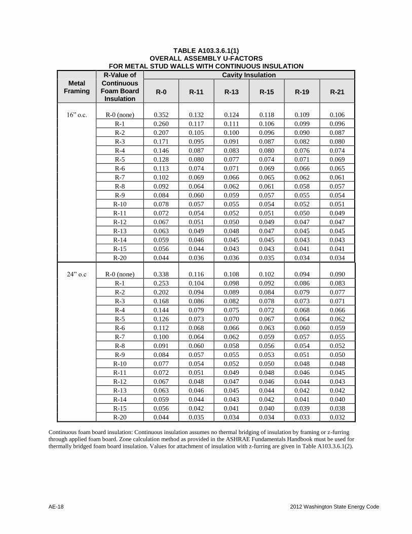
A103.3.6.1 Metal stud wall, overall assembly
U-factors. Tables A103.3.6.1(1) and
A103.6.1(2): Assumes metal studs spaced on 16
or 24 inch centers with insulation installed to fill
wall cavities. Continuous rigid board insulation
is applied without creating uninsulated voids in
the wall assembly.
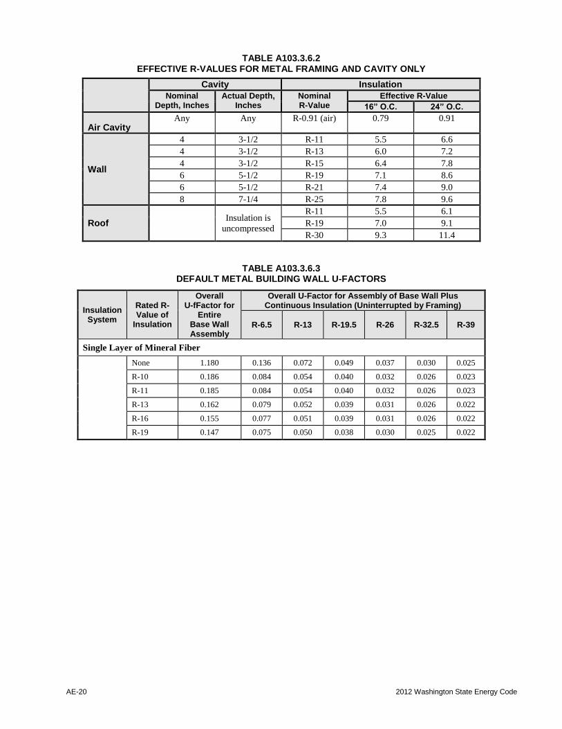
A103.3.6.2 Metal stud wall, effective R-values
for metal framing and cavity only. Table
A103.3.6.2: These values may be used for the
metal-framing/cavity layers in walls with metal
studs spaced on 16- or 24-inch centers with
insulation installed to fill wall cavities in lieu of
using the zone method provided in Chapter 25 of
the ASHRAE Fundamentals Handbook.
A103.3.6.3 Metal building wall. Table
A103.3.6.3: A wall whose structure consists of
metal spanning panels supported by steel
structural members (does not include spandrel
glass or metal panels in curtain wall systems).
The first nominal R-value is for insulation
compressed between metal wall panels and the
steel structure. For double-layer installations,
the second rated R-value of insulation is for
insulation installed from the inside, covering the
girts. For continuous insulation (e.g., insulation
boards) it is assumed that the insulation boards
are installed on the inside of the girts and
uninterrupted by the framing members.
Insulation exposed to the conditioned space or
semi-heated space shall have a facing, and all
insulation seams shall be continuously sealed to
provide a continuous air barrier.
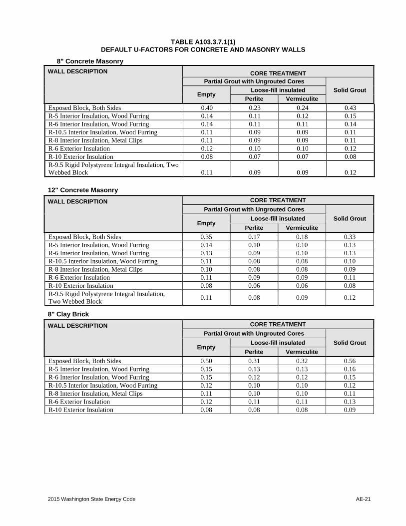
A103.3.7 Concrete and masonry walls.
A103.3.7.1 Concrete masonry walls. The
nominal R-values in Tables A103.3.7.1(1) and
A103.3.7.1(2) may be used for purposes of
calculating concrete masonry wall section U-
factors in lieu of the ASHRAE isothermal planes
calculation method as provided in Chapter 27 of
the ASHRAE Fundamentals Handbook
A103.3.7.2 Peripheral edges of intermediate
concrete floors. See Table A103.3.7.2.
.
AE-18 2012 Washington State Energy Code
TABLE A103.3.6.1(1) OVERALL ASSEMBLY U-FACTORS
FOR METAL STUD WALLS WITH CONTINUOUS INSULATION
R-Value of Cavity Insulation
Metal Framing
Continuous Foam Board
Insulation R-0 R-11 R-13 R-15 R-19 R-21
16” o.c.
R-0 (none)
0.352
0.132
0.124
0.118
0.109
0.106
R-1 0.260 0.117 0.111 0.106 0.099 0.096
R-2 0.207 0.105 0.100 0.096 0.090 0.087
R-3 0.171 0.095 0.091 0.087 0.082 0.080
R-4 0.146 0.087 0.083 0.080 0.076 0.074
R-5 0.128 0.080 0.077 0.074 0.071 0.069
R-6 0.113 0.074 0.071 0.069 0.066 0.065
R-7 0.102 0.069 0.066 0.065 0.062 0.061
R-8 0.092 0.064 0.062 0.061 0.058 0.057
R-9 0.084 0.060 0.059 0.057 0.055 0.054
R-10 0.078 0.057 0.055 0.054 0.052 0.051
R-11 0.072 0.054 0.052 0.051 0.050 0.049
R-12 0.067 0.051 0.050 0.049 0.047 0.047
R-13 0.063 0.049 0.048 0.047 0.045 0.045
R-14 0.059 0.046 0.045 0.045 0.043 0.043
R-15 0.056 0.044 0.043 0.043 0.041 0.041
R-20 0.044 0.036 0.036 0.035 0.034 0.034
24” o.c
R-0 (none)
0.338
0.116
0.108
0.102
0.094
0.090
R-1 0.253 0.104 0.098 0.092 0.086 0.083
R-2 0.202 0.094 0.089 0.084 0.079 0.077
R-3 0.168 0.086 0.082 0.078 0.073 0.071
R-4 0.144 0.079 0.075 0.072 0.068 0.066
R-5 0.126 0.073 0.070 0.067 0.064 0.062
R-6 0.112 0.068 0.066 0.063 0.060 0.059
R-7 0.100 0.064 0.062 0.059 0.057 0.055
R-8 0.091 0.060 0.058 0.056 0.054 0.052
R-9 0.084 0.057 0.055 0.053 0.051 0.050
R-10 0.077 0.054 0.052 0.050 0.048 0.048
R-11 0.072 0.051 0.049 0.048 0.046 0.045
R-12 0.067 0.048 0.047 0.046 0.044 0.043
R-13 0.063 0.046 0.045 0.044 0.042 0.042
R-14 0.059 0.044 0.043 0.042 0.041 0.040
R-15 0.056 0.042 0.041 0.040 0.039 0.038
R-20 0.044 0.035 0.034 0.034 0.033 0.032
Continuous foam board insulation: Continuous insulation assumes no thermal bridging of insulation by framing or z-furring
through applied foam board. Zone calculation method as provided in the ASHRAE Fundamentals Handbook must be used for
thermally bridged foam board insulation. Values for attachment of insulation with z-furring are given in Table A103.3.6.1(2).
2015 Washington State Energy Code AE-19
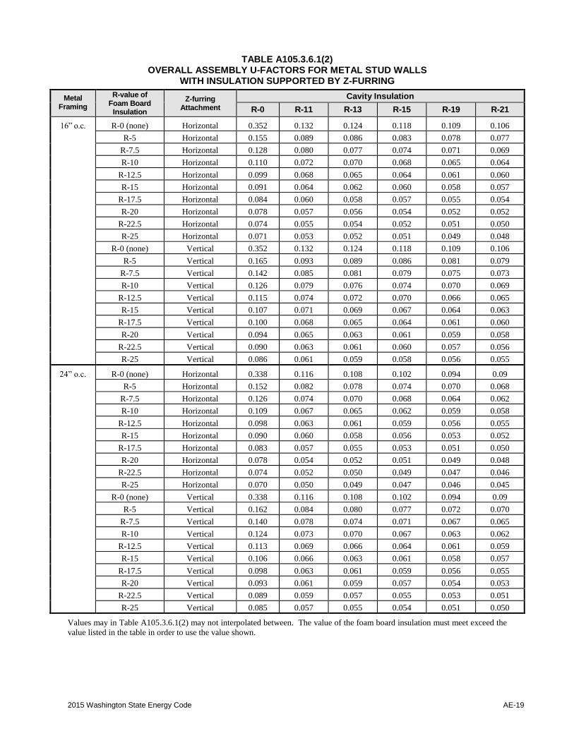
TABLE A105.3.6.1(2) OVERALL ASSEMBLY U-FACTORS FOR METAL STUD WALLS
WITH INSULATION SUPPORTED BY Z-FURRING
Metal Framing
R-value of Foam Board
Insulation
Z-furring Attachment
Cavity Insulation
R-0 R-11 R-13 R-15 R-19 R-21
16” o.c. R-0 (none) Horizontal 0.352 0.132 0.124 0.118 0.109 0.106
R-5 Horizontal 0.155 0.089 0.086 0.083 0.078 0.077
R-7.5 Horizontal 0.128 0.080 0.077 0.074 0.071 0.069
R-10 Horizontal 0.110 0.072 0.070 0.068 0.065 0.064
R-12.5 Horizontal 0.099 0.068 0.065 0.064 0.061 0.060
R-15 Horizontal 0.091 0.064 0.062 0.060 0.058 0.057
R-17.5 Horizontal 0.084 0.060 0.058 0.057 0.055 0.054
R-20 Horizontal 0.078 0.057 0.056 0.054 0.052 0.052
R-22.5 Horizontal 0.074 0.055 0.054 0.052 0.051 0.050
R-25 Horizontal 0.071 0.053 0.052 0.051 0.049 0.048
R-0 (none) Vertical 0.352 0.132 0.124 0.118 0.109 0.106
R-5 Vertical 0.165 0.093 0.089 0.086 0.081 0.079
R-7.5 Vertical 0.142 0.085 0.081 0.079 0.075 0.073
R-10 Vertical 0.126 0.079 0.076 0.074 0.070 0.069
R-12.5 Vertical 0.115 0.074 0.072 0.070 0.066 0.065
R-15 Vertical 0.107 0.071 0.069 0.067 0.064 0.063
R-17.5 Vertical 0.100 0.068 0.065 0.064 0.061 0.060
R-20 Vertical 0.094 0.065 0.063 0.061 0.059 0.058
R-22.5 Vertical 0.090 0.063 0.061 0.060 0.057 0.056
R-25 Vertical 0.086 0.061 0.059 0.058 0.056 0.055
24” o.c. R-0 (none) Horizontal 0.338 0.116 0.108 0.102 0.094 0.09
R-5 Horizontal 0.152 0.082 0.078 0.074 0.070 0.068
R-7.5 Horizontal 0.126 0.074 0.070 0.068 0.064 0.062
R-10 Horizontal 0.109 0.067 0.065 0.062 0.059 0.058
R-12.5 Horizontal 0.098 0.063 0.061 0.059 0.056 0.055
R-15 Horizontal 0.090 0.060 0.058 0.056 0.053 0.052
R-17.5 Horizontal 0.083 0.057 0.055 0.053 0.051 0.050
R-20 Horizontal 0.078 0.054 0.052 0.051 0.049 0.048
R-22.5 Horizontal 0.074 0.052 0.050 0.049 0.047 0.046
R-25 Horizontal 0.070 0.050 0.049 0.047 0.046 0.045
R-0 (none) Vertical 0.338 0.116 0.108 0.102 0.094 0.09
R-5 Vertical 0.162 0.084 0.080 0.077 0.072 0.070
R-7.5 Vertical 0.140 0.078 0.074 0.071 0.067 0.065
R-10 Vertical 0.124 0.073 0.070 0.067 0.063 0.062
R-12.5 Vertical 0.113 0.069 0.066 0.064 0.061 0.059
R-15 Vertical 0.106 0.066 0.063 0.061 0.058 0.057
R-17.5 Vertical 0.098 0.063 0.061 0.059 0.056 0.055
R-20 Vertical 0.093 0.061 0.059 0.057 0.054 0.053
R-22.5 Vertical 0.089 0.059 0.057 0.055 0.053 0.051
R-25 Vertical 0.085 0.057 0.055 0.054 0.051 0.050
Values may in Table A105.3.6.1(2) may not interpolated between. The value of the foam board insulation must meet exceed the
value listed in the table in order to use the value shown.
AE-20 2012 Washington State Energy Code
TABLE A103.3.6.2 EFFECTIVE R-VALUES FOR METAL FRAMING AND CAVITY ONLY
Cavity Insulation
Nominal Depth, Inches
Actual Depth, Inches
Nominal R-Value
Effective R-Value
16” O.C. 24” O.C.
Air Cavity Any Any R-0.91 (air) 0.79 0.91
Wall
4 3-1/2 R-11 5.5 6.6
4 3-1/2 R-13 6.0 7.2
4 3-1/2 R-15 6.4 7.8
6 5-1/2 R-19 7.1 8.6
6 5-1/2 R-21 7.4 9.0
8 7-1/4 R-25 7.8 9.6
Roof
Insulation is
uncompressed
R-11 5.5 6.1
R-19 7.0 9.1
R-30 9.3 11.4
TABLE A103.3.6.3 DEFAULT METAL BUILDING WALL U-FACTORS
Insulation System
Rated R-Value of
Insulation
Overall U-fFactor for
Entire Base Wall Assembly
Overall U-Factor for Assembly of Base Wall Plus Continuous Insulation (Uninterrupted by Framing)
R-6.5 R-13 R-19.5 R-26 R-32.5 R-39
Single Layer of Mineral Fiber
None 1.180 0.136 0.072 0.049 0.037 0.030 0.025
R-10 0.186 0.084 0.054 0.040 0.032 0.026 0.023
R-11 0.185 0.084 0.054 0.040 0.032 0.026 0.023
R-13 0.162 0.079 0.052 0.039 0.031 0.026 0.022
R-16 0.155 0.077 0.051 0.039 0.031 0.026 0.022
R-19 0.147 0.075 0.050 0.038 0.030 0.025 0.022
2015 Washington State Energy Code AE-21
TABLE A103.3.7.1(1) DEFAULT U-FACTORS FOR CONCRETE AND MASONRY WALLS
8" Concrete Masonry
WALL DESCRIPTION CORE TREATMENT
Partial Grout with Ungrouted Cores
Solid Grout Empty
Loose-fill insulated
Perlite Vermiculite
Exposed Block, Both Sides 0.40 0.23 0.24 0.43
R-5 Interior Insulation, Wood Furring 0.14 0.11 0.12 0.15
R-6 Interior Insulation, Wood Furring 0.14 0.11 0.11 0.14
R-10.5 Interior Insulation, Wood Furring 0.11 0.09 0.09 0.11
R-8 Interior Insulation, Metal Clips 0.11 0.09 0.09 0.11
R-6 Exterior Insulation 0.12 0.10 0.10 0.12
R-10 Exterior Insulation 0.08 0.07 0.07 0.08
R-9.5 Rigid Polystyrene Integral Insulation, Two
Webbed Block
0.11
0.09
0.09
0.12
12" Concrete Masonry
WALL DESCRIPTION CORE TREATMENT
Partial Grout with Ungrouted Cores
Solid Grout Empty
Loose-fill insulated
Perlite Vermiculite
Exposed Block, Both Sides 0.35 0.17 0.18 0.33
R-5 Interior Insulation, Wood Furring 0.14 0.10 0.10 0.13
R-6 Interior Insulation, Wood Furring 0.13 0.09 0.10 0.13
R-10.5 Interior Insulation, Wood Furring 0.11 0.08 0.08 0.10
R-8 Interior Insulation, Metal Clips 0.10 0.08 0.08 0.09
R-6 Exterior Insulation 0.11 0.09 0.09 0.11
R-10 Exterior Insulation 0.08 0.06 0.06 0.08
R-9.5 Rigid Polystyrene Integral Insulation,
Two Webbed Block 0.11 0.08 0.09 0.12
8" Clay Brick
WALL DESCRIPTION CORE TREATMENT
Partial Grout with Ungrouted Cores
Solid Grout Empty
Loose-fill insulated
Perlite Vermiculite
Exposed Block, Both Sides 0.50 0.31 0.32 0.56
R-5 Interior Insulation, Wood Furring 0.15 0.13 0.13 0.16
R-6 Interior Insulation, Wood Furring 0.15 0.12 0.12 0.15
R-10.5 Interior Insulation, Wood Furring 0.12 0.10 0.10 0.12
R-8 Interior Insulation, Metal Clips 0.11 0.10 0.10 0.11
R-6 Exterior Insulation 0.12 0.11 0.11 0.13
R-10 Exterior Insulation 0.08 0.08 0.08 0.09
AE-22 2012 Washington State Energy Code
TABLE A103.3.7.1(1) – continued DEFAULT U-FACTORS FOR CONCRETE AND MASONRY WALLS
6" Concrete Poured or Precast
WALL DESCRIPTION CORE TREATMENT
Partial Grout with Ungrouted Cores
Solid Grout Empty
Loose-fill insulated
Perlite Vermiculite
Exposed Concrete, Both Sides NA NA NA 0.61
R-5 Interior Insulation, Wood Furring NA NA NA 0.16
R-6 Interior Insulation, Wood Furring NA NA NA 0.15
R-10.5 Interior Insulation, Wood Furring NA NA NA 0.12
R-8 Interior Insulation, Metal Clips NA NA NA 0.12
R-6 Exterior Insulation NA NA NA 0.13
R-10 Exterior Insulation NA NA NA 0.09
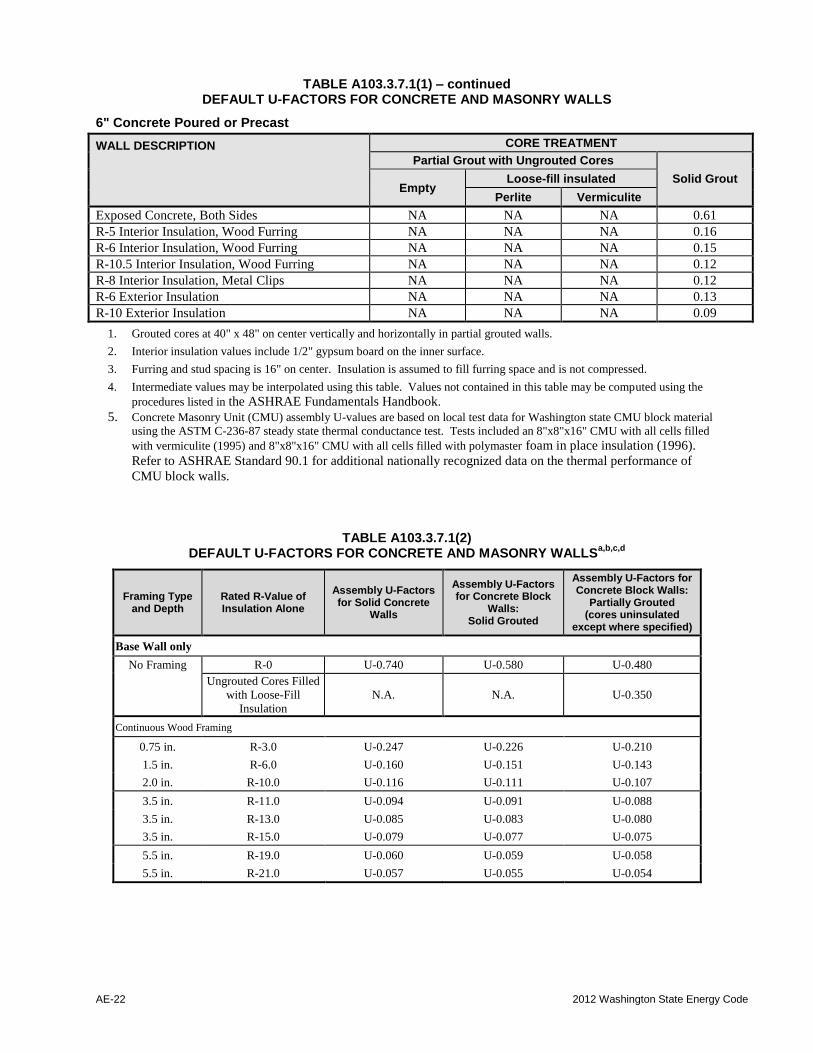
1. Grouted cores at 40" x 48" on center vertically and horizontally in partial grouted walls.
2. Interior insulation values include 1/2" gypsum board on the inner surface.
3. Furring and stud spacing is 16" on center. Insulation is assumed to fill furring space and is not compressed.
4. Intermediate values may be interpolated using this table. Values not contained in this table may be computed using the
procedures listed in the ASHRAE Fundamentals Handbook.
5. Concrete Masonry Unit (CMU) assembly U-values are based on local test data for Washington state CMU block material
using the ASTM C-236-87 steady state thermal conductance test. Tests included an 8"x8"x16" CMU with all cells filled
with vermiculite (1995) and 8"x8"x16" CMU with all cells filled with polymaster foam in place insulation (1996).
Refer to ASHRAE Standard 90.1 for additional nationally recognized data on the thermal performance of
CMU block walls.
TABLE A103.3.7.1(2) DEFAULT U-FACTORS FOR CONCRETE AND MASONRY WALLS
a,b,c,d
Framing Type and Depth
Rated R-Value of Insulation Alone
Assembly U-Factors for Solid Concrete
Walls
Assembly U-Factors for Concrete Block
Walls: Solid Grouted
Assembly U-Factors for Concrete Block Walls:
Partially Grouted (cores uninsulated
except where specified)
Base Wall only
No Framing R-0 U-0.740 U-0.580 U-0.480
Ungrouted Cores Filled
with Loose-Fill
Insulation
N.A. N.A. U-0.350
Continuous Wood Framing
0.75 in. R-3.0 U-0.247 U-0.226 U-0.210
1.5 in. R-6.0 U-0.160 U-0.151 U-0.143
2.0 in. R-10.0 U-0.116 U-0.111 U-0.107
3.5 in. R-11.0 U-0.094 U-0.091 U-0.088
3.5 in. R-13.0 U-0.085 U-0.083 U-0.080
3.5 in. R-15.0 U-0.079 U-0.077 U-0.075
5.5 in. R-19.0 U-0.060 U-0.059 U-0.058
5.5 in. R-21.0 U-0.057 U-0.055 U-0.054
2015 Washington State Energy Code AE-23
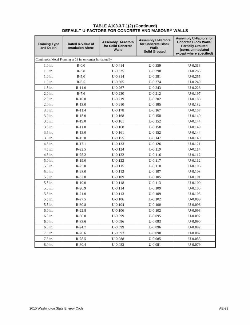
TABLE A103.3.7.1(2) (Continued) DEFAULT U-FACTORS FOR CONCRETE AND MASONRY WALLS
Framing Type and Depth
Rated R-Value of Insulation Alone
Assembly U-Factors for Solid Concrete
Walls
Assembly U-Factors for Concrete Block
Walls: Solid Grouted
Assembly U-Factors for Concrete Block Walls:
Partially Grouted (cores uninsulated
except where specified)
Continuous Metal Framing at 24 in. on center horizontally
1.0 in. R-0.0 U-0.414 U-0.359 U-0.318
1.0 in. R-3.8 U-0.325 U-0.290 U-0.263
1.0 in. R-5.0 U-0.314 U-0.281 U-0.255
1.0 in. R-6.5 U-0.305 U-0.274 U-0.249
1.5 in. R-11.0 U-0.267 U-0.243 U-0.223
2.0 in. R-7.6 U-0.230 U-0.212 U-0.197
2.0 in. R-10.0 U-0.219 U-0.202 U-0.188
2.0 in. R-13.0 U-0.210 U-0.195 U-0.182
3.0 in. R-11.4 U-0.178 U-0.167 U-0.157
3.0 in. R-15.0 U-0.168 U-0.158 U-0.149
3.0 in. R-19.0 U-0.161 U-0.152 U-0.144
3.5 in. R-11.0 U-0.168 U-0.158 U-0.149
3.5 in. R-13.0 U-0.161 U-0.152 U-0.144
3.5 in. R-15.0 U-0.155 U-0.147 U-0.140
4.5 in. R-17.1 U-0.133 U-0.126 U-0.121
4.5 in. R-22.5 U-0.124 U-0.119 U-0.114
4.5 in. R-25.2 U-0.122 U-0.116 U-0.112
5.0 in. R-19.0 U-0.122 U-0.117 U-0.112
5.0 in. R-25.0 U-0.115 U-0.110 U-0.106
5.0 in. R-28.0 U-0.112 U-0.107 U-0.103
5.0 in. R-32.0 U-0.109 U-0.105 U-0.101
5.5 in. R-19.0 U-0.118 U-0.113 U-0.109
5.5 in. R-20.9 U-0.114 U-0.109 U-0.105
5.5 in. R-21.0 U-0.113 U-0.109 U-0.105
5.5 in. R-27.5 U-0.106 U-0.102 U-0.099
5.5 in. R-30.8 U-0.104 U-0.100 U-0.096
6.0 in. R-22.8 U-0.106 U-0.102 U-0.098
6.0 in. R-30.0 U-0.099 U-0.095 U-0.092
6.0 in. R-33.6 U-0.096 U-0.093 U-0.090
6.5 in. R-24.7 U-0.099 U-0.096 U-0.092
7.0 in. R-26.6 U-0.093 U-0.090 U-0.087
7.5 in. R-28.5 U-0.088 U-0.085 U-0.083
8.0 in. R-30.4 U-0.083 U-0.081 U-0.079
AE-24 2012 Washington State Energy Code
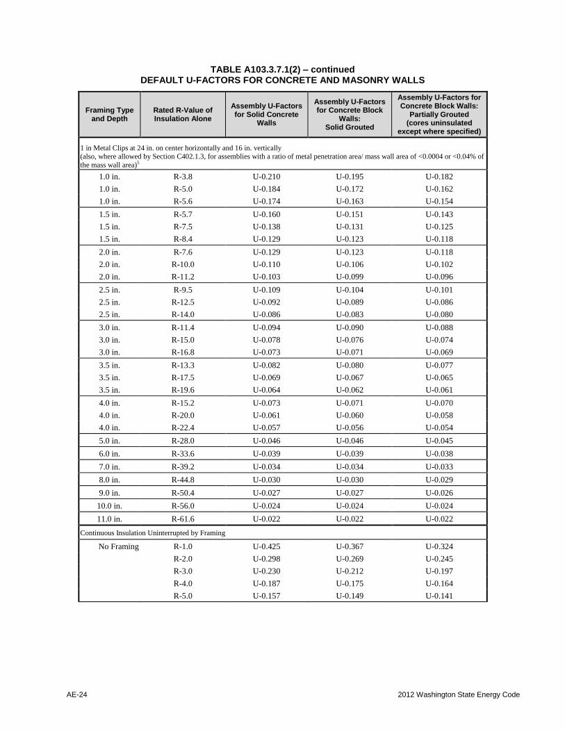
TABLE A103.3.7.1(2) – continued DEFAULT U-FACTORS FOR CONCRETE AND MASONRY WALLS
Framing Type and Depth
Rated R-Value of Insulation Alone
Assembly U-Factors for Solid Concrete
Walls
Assembly U-Factors for Concrete Block
Walls: Solid Grouted
Assembly U-Factors for Concrete Block Walls:
Partially Grouted (cores uninsulated
except where specified)
1 in Metal Clips at 24 in. on center horizontally and 16 in. vertically (also, where allowed by Section C402.1.3, for assemblies with a ratio of metal penetration area/ mass wall area of <0.0004 or <0.04% of
the mass wall area)5
1.0 in. R-3.8 U-0.210 U-0.195 U-0.182
1.0 in. R-5.0 U-0.184 U-0.172 U-0.162
1.0 in. R-5.6 U-0.174 U-0.163 U-0.154
1.5 in. R-5.7 U-0.160 U-0.151 U-0.143
1.5 in. R-7.5 U-0.138 U-0.131 U-0.125
1.5 in. R-8.4 U-0.129 U-0.123 U-0.118
2.0 in. R-7.6 U-0.129 U-0.123 U-0.118
2.0 in. R-10.0 U-0.110 U-0.106 U-0.102
2.0 in. R-11.2 U-0.103 U-0.099 U-0.096
2.5 in. R-9.5 U-0.109 U-0.104 U-0.101
2.5 in. R-12.5 U-0.092 U-0.089 U-0.086
2.5 in. R-14.0 U-0.086 U-0.083 U-0.080
3.0 in. R-11.4 U-0.094 U-0.090 U-0.088
3.0 in. R-15.0 U-0.078 U-0.076 U-0.074
3.0 in. R-16.8 U-0.073 U-0.071 U-0.069
3.5 in. R-13.3 U-0.082 U-0.080 U-0.077
3.5 in. R-17.5 U-0.069 U-0.067 U-0.065
3.5 in. R-19.6 U-0.064 U-0.062 U-0.061
4.0 in. R-15.2 U-0.073 U-0.071 U-0.070
4.0 in. R-20.0 U-0.061 U-0.060 U-0.058
4.0 in. R-22.4 U-0.057 U-0.056 U-0.054
5.0 in. R-28.0 U-0.046 U-0.046 U-0.045
6.0 in. R-33.6 U-0.039 U-0.039 U-0.038
7.0 in. R-39.2 U-0.034 U-0.034 U-0.033
8.0 in. R-44.8 U-0.030 U-0.030 U-0.029
9.0 in. R-50.4 U-0.027 U-0.027 U-0.026
10.0 in. R-56.0 U-0.024 U-0.024 U-0.024
11.0 in. R-61.6 U-0.022 U-0.022 U-0.022
Continuous Insulation Uninterrupted by Framing
No Framing R-1.0 U-0.425 U-0.367 U-0.324
R-2.0 U-0.298 U-0.269 U-0.245
R-3.0 U-0.230 U-0.212 U-0.197
R-4.0 U-0.187 U-0.175 U-0.164
R-5.0 U-0.157 U-0.149 U-0.141
2015 Washington State Energy Code AE-25
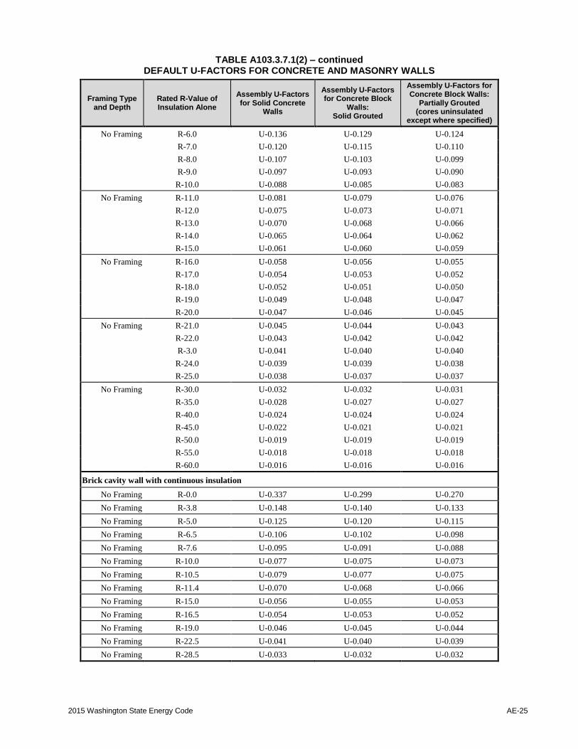
TABLE A103.3.7.1(2) – continued DEFAULT U-FACTORS FOR CONCRETE AND MASONRY WALLS
Framing Type and Depth
Rated R-Value of Insulation Alone
Assembly U-Factors for Solid Concrete
Walls
Assembly U-Factors for Concrete Block
Walls: Solid Grouted
Assembly U-Factors for Concrete Block Walls:
Partially Grouted (cores uninsulated
except where specified)
No Framing R-6.0 U-0.136 U-0.129 U-0.124
R-7.0 U-0.120 U-0.115 U-0.110
R-8.0 U-0.107 U-0.103 U-0.099
R-9.0 U-0.097 U-0.093 U-0.090
R-10.0 U-0.088 U-0.085 U-0.083
No Framing R-11.0 U-0.081 U-0.079 U-0.076
R-12.0 U-0.075 U-0.073 U-0.071
R-13.0 U-0.070 U-0.068 U-0.066
R-14.0 U-0.065 U-0.064 U-0.062
R-15.0 U-0.061 U-0.060 U-0.059
No Framing R-16.0 U-0.058 U-0.056 U-0.055
R-17.0 U-0.054 U-0.053 U-0.052
R-18.0 U-0.052 U-0.051 U-0.050
R-19.0 U-0.049 U-0.048 U-0.047
R-20.0 U-0.047 U-0.046 U-0.045
No Framing R-21.0 U-0.045 U-0.044 U-0.043
R-22.0 U-0.043 U-0.042 U-0.042
R-3.0 U-0.041 U-0.040 U-0.040
R-24.0 U-0.039 U-0.039 U-0.038
R-25.0 U-0.038 U-0.037 U-0.037
No Framing R-30.0 U-0.032 U-0.032 U-0.031
R-35.0 U-0.028 U-0.027 U-0.027
R-40.0 U-0.024 U-0.024 U-0.024
R-45.0 U-0.022 U-0.021 U-0.021
R-50.0 U-0.019 U-0.019 U-0.019
R-55.0 U-0.018 U-0.018 U-0.018
R-60.0 U-0.016 U-0.016 U-0.016
Brick cavity wall with continuous insulation
No Framing R-0.0 U-0.337 U-0.299 U-0.270
No Framing R-3.8 U-0.148 U-0.140 U-0.133
No Framing R-5.0 U-0.125 U-0.120 U-0.115
No Framing R-6.5 U-0.106 U-0.102 U-0.098
No Framing R-7.6 U-0.095 U-0.091 U-0.088
No Framing R-10.0 U-0.077 U-0.075 U-0.073
No Framing R-10.5 U-0.079 U-0.077 U-0.075
No Framing R-11.4 U-0.070 U-0.068 U-0.066
No Framing R-15.0 U-0.056 U-0.055 U-0.053
No Framing R-16.5 U-0.054 U-0.053 U-0.052
No Framing R-19.0 U-0.046 U-0.045 U-0.044
No Framing R-22.5 U-0.041 U-0.040 U-0.039
No Framing R-28.5 U-0.033 U-0.032 U-0.032

AE-26 2012 Washington State Energy Code
TABLE A103.3.7.1(2) – continued DEFAULT U-FACTORS FOR CONCRETE AND MASONRY WALLS
Framing Type and Depth
Rated R-Value of Insulation Alone
Assembly U-Factors for Solid Concrete
Walls
Assembly U-Factors for Concrete Block
Walls: Solid Grouted
Assembly U-Factors for Concrete Block Walls:
Partially Grouted (cores uninsulated
except where specified)
Continuous Insulation Uninterrupted by Framing with Stucco and Continuous Metal Framing at 24 in. on center horizontally
1.0 in. R-0.0 + R-19 c.i. U-0.047 U-0.046 U-0.045
1.0 in. R-3.8 + R-19 c.i. U-0.045 U-0.044 U-0.044
1.0 in. R-5.0 + R-19 c.i. U-0.045 U-0.044 U-0.043
1.0 in. R-6.5 + R-19 c.i. U-0.045 U-0.044 U-0.043
1.5 in. R-11.0 + R-19 c.i. U-0.044 U-0.043 U-0.043
2.0 in. R-7.6 + R-19 c.i. U-0.043 U-0.042 U-0.041
2.0 in. R-10.0 + R-19 c.i. U-0.042 U-0.041 U-0.041
2.0 in. R-13.0 + R-19 c.i. U-0.042 U-0.041 U-0.041
3.0 in. R-11.4 + R-19 c.i. U-0.041 U-0.040 U-0.039
3.0 in. R-15.0 + R-19 c.i. U-0.040 U-0.039 U-0.039
3.0 in. R-19.0 + R-19 c.i. U-0.040 U-0.039 U-0.038
3.5 in. R-11.0 + R-19 c.i. U-0.040 U-0.039 U-0.039
3.5 in. R-13.0 + R-19 c.i. U-0.040 U-0.039 U-0.038
5.0 in. R-19.0 + R-19 c.i. U-0.037 U-0.036 U-0.036
5.0 in. R-25.0 + R-19 c.i. U-0.036 U-0.035 U-0.035
5.0 in. R-32.5 + R-19 c.i. U-0.035 U-0.035 U-0.034
5.5 in. R-19.0 + R-19 c.i. U-0.036 U-0.036 U-0.035
5.5 in. R-21.0 + R-19 c.i. U-0.035 U-0.035 U-0.035
Notes for Default Table A103.3.7.1(1):
a. It is acceptable to use the U-factors in Table A103.3.7.1(2) for all concrete and masonry walls, provided that the grouting is equal to or less than that specified.
-For ungrouted walls, use the partially grouted column.
-For metal studs and z-furring, use the continuous-metal-framing category.
-For discontinuous metal clips 1 inch square or smaller, use the metal-clip category.
-For insulation that is attached without any framing members (e.g. glued), use the continuous-insulation uninterrupted-by-framing category. Continuous insulation may be installed on the interior or exterior of masonry walls, or between stand-alone walls in
multilayer masonry walls, or on the interior or exterior of the concrete.
b. For Table A103.3.7.1(2), the U-factor includes R-0.17 for exterior air film and R-0.68 for interior air film-vertical surfaces. For insulatedwalls, the U-factor also includes R-0.45 for 0.5 in. gypsum board. U-factors are provided for the following configurations:
1. Concrete wall: 8-in. normal weight concrete wall with a density of 145 lb/ft3.
2. Solid grouted concrete block wall: 8-in. medium weight ASTM C90 concrete block with a density of 115 lb/ft3 and solid grouted
cores.
3. Partially grouted concrete block wall: 8-in. medium weight ASTM C90 concrete block with a density of 115 lb/ft3 having
reinforcing steel every 32 in. vertically and every 48 in. horizontally, with cores grouted in those areas only. Other cores are filled
with insulating material only if there is no other insulation.
c. For walls with insulation contained in a framing layer, the U-factors in Table A103.3.7.1(4) assume contact (and thermal bridging)
between the mass wall and other framing. For wall assemblies with multiple layers where the wood or metal framing layer does notcontact the concrete or masonry layer (i.e., walls with an airspace between the stud wall layer and the mass wall layer), it is acceptable to
use the appropriate wood or metal frame wall default U-factors in Tables A103.3.1 or A103.3.6.1. Note: It is acceptable to use this
approach where the insulation extends beyond the framing and is in contact with the mass wall layer (e.g. a nominal four-inch metal studcontaining insulation that is nominally six inches thick and therefore extends two inches beyond the back of the metal stud).
d. Except for wall assemblies qualifying for note 3, if not taken from Table A103.3.7.1(2), mass wall U-factors shall be determined inaccordance with ASHRAE 90.1, Appendix A, Section A3.1 and Tables A3.1A to A3.1D, or Section A9.4.
2015 Washington State Energy Code AE-27
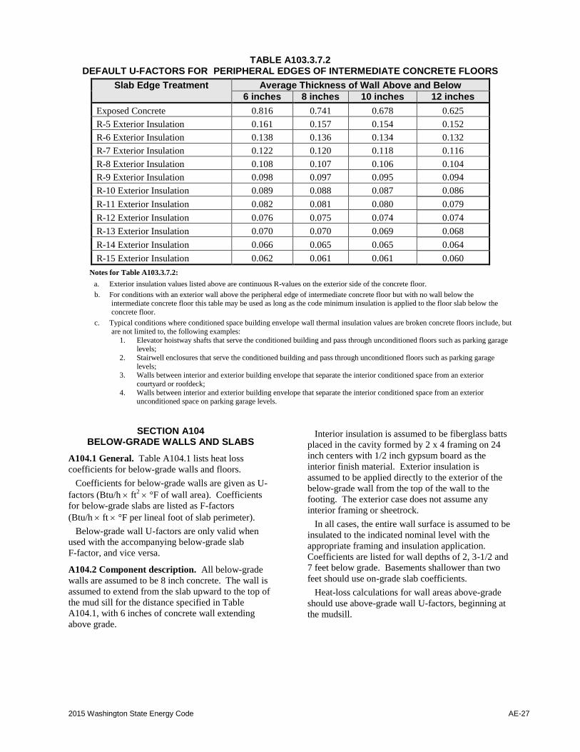
TABLE A103.3.7.2 DEFAULT U-FACTORS FOR PERIPHERAL EDGES OF INTERMEDIATE CONCRETE FLOORS
Slab Edge Treatment Average Thickness of Wall Above and Below
6 inches 8 inches 10 inches 12 inches
Exposed Concrete 0.816 0.741 0.678 0.625
R-5 Exterior Insulation 0.161 0.157 0.154 0.152
R-6 Exterior Insulation 0.138 0.136 0.134 0.132
R-7 Exterior Insulation 0.122 0.120 0.118 0.116
R-8 Exterior Insulation 0.108 0.107 0.106 0.104
R-9 Exterior Insulation 0.098 0.097 0.095 0.094
R-10 Exterior Insulation 0.089 0.088 0.087 0.086
R-11 Exterior Insulation 0.082 0.081 0.080 0.079
R-12 Exterior Insulation 0.076 0.075 0.074 0.074
R-13 Exterior Insulation 0.070 0.070 0.069 0.068
R-14 Exterior Insulation 0.066 0.065 0.065 0.064
R-15 Exterior Insulation 0.062 0.061 0.061 0.060
Notes for Table A103.3.7.2:
a. Exterior insulation values listed above are continuous R-values on the exterior side of the concrete floor.
b. For conditions with an exterior wall above the peripheral edge of intermediate concrete floor but with no wall below the intermediate concrete floor this table may be used as long as the code minimum insulation is applied to the floor slab below the
concrete floor.
c. Typical conditions where conditioned space building envelope wall thermal insulation values are broken concrete floors include, but are not limited to, the following examples:
1. Elevator hoistway shafts that serve the conditioned building and pass through unconditioned floors such as parking garage levels;
2. Stairwell enclosures that serve the conditioned building and pass through unconditioned floors such as parking garage
levels;3. Walls between interior and exterior building envelope that separate the interior conditioned space from an exterior
courtyard or roofdeck;
4. Walls between interior and exterior building envelope that separate the interior conditioned space from an exterior unconditioned space on parking garage levels.
SECTION A104 BELOW-GRADE WALLS AND SLABS
A104.1 General. Table A104.1 lists heat loss
coefficients for below-grade walls and floors.
Coefficients for below-grade walls are given as U-
factors (Btu/h ft2 °F of wall area). Coefficients
for below-grade slabs are listed as F-factors
(Btu/h ft °F per lineal foot of slab perimeter).
Below-grade wall U-factors are only valid when
used with the accompanying below-grade slab
F-factor, and vice versa.
A104.2 Component description. All below-grade
walls are assumed to be 8 inch concrete. The wall is
assumed to extend from the slab upward to the top of
the mud sill for the distance specified in Table
A104.1, with 6 inches of concrete wall extending
above grade.
Interior insulation is assumed to be fiberglass batts
placed in the cavity formed by 2 x 4 framing on 24
inch centers with 1/2 inch gypsum board as the
interior finish material. Exterior insulation is
assumed to be applied directly to the exterior of the
below-grade wall from the top of the wall to the
footing. The exterior case does not assume any
interior framing or sheetrock.
In all cases, the entire wall surface is assumed to be
insulated to the indicated nominal level with the
appropriate framing and insulation application.
Coefficients are listed for wall depths of 2, 3-1/2 and
7 feet below grade. Basements shallower than two
feet should use on-grade slab coefficients.
Heat-loss calculations for wall areas above-grade
should use above-grade wall U-factors, beginning at
the mudsill.
AE-28 2012 Washington State Energy Code
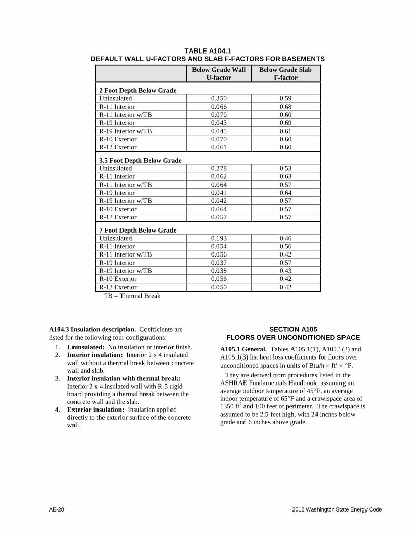
TABLE A104.1 DEFAULT WALL U-FACTORS AND SLAB F-FACTORS FOR BASEMENTS
Below Grade Wall
U-factor
Below Grade Slab
F-factor
2 Foot Depth Below Grade
Uninsulated 0.350 0.59
R-11 Interior 0.066 0.68
R-11 Interior w/TB 0.070 0.60
R-19 Interior 0.043 0.69
R-19 Interior w/TB 0.045 0.61
R-10 Exterior 0.070 0.60
R-12 Exterior 0.061 0.60
3.5 Foot Depth Below Grade
Uninsulated 0.278 0.53
R-11 Interior 0.062 0.63
R-11 Interior w/TB 0.064 0.57
R-19 Interior 0.041 0.64
R-19 Interior w/TB 0.042 0.57
R-10 Exterior 0.064 0.57
R-12 Exterior 0.057 0.57
7 Foot Depth Below Grade
Uninsulated 0.193 0.46
R-11 Interior 0.054 0.56
R-11 Interior w/TB 0.056 0.42
R-19 Interior 0.037 0.57
R-19 Interior w/TB 0.038 0.43
R-10 Exterior 0.056 0.42
R-12 Exterior 0.050 0.42
TB = Thermal Break
A104.3 Insulation description. Coefficients are
listed for the following four configurations:
1. Uninsulated: No insulation or interior finish.
2. Interior insulation: Interior 2 x 4 insulated
wall without a thermal break between concrete
wall and slab.
3. Interior insulation with thermal break: Interior 2 x 4 insulated wall with R-5 rigid
board providing a thermal break between the
concrete wall and the slab.
4. Exterior insulation: Insulation applied
directly to the exterior surface of the concrete
wall.
SECTION A105 FLOORS OVER UNCONDITIONED SPACE
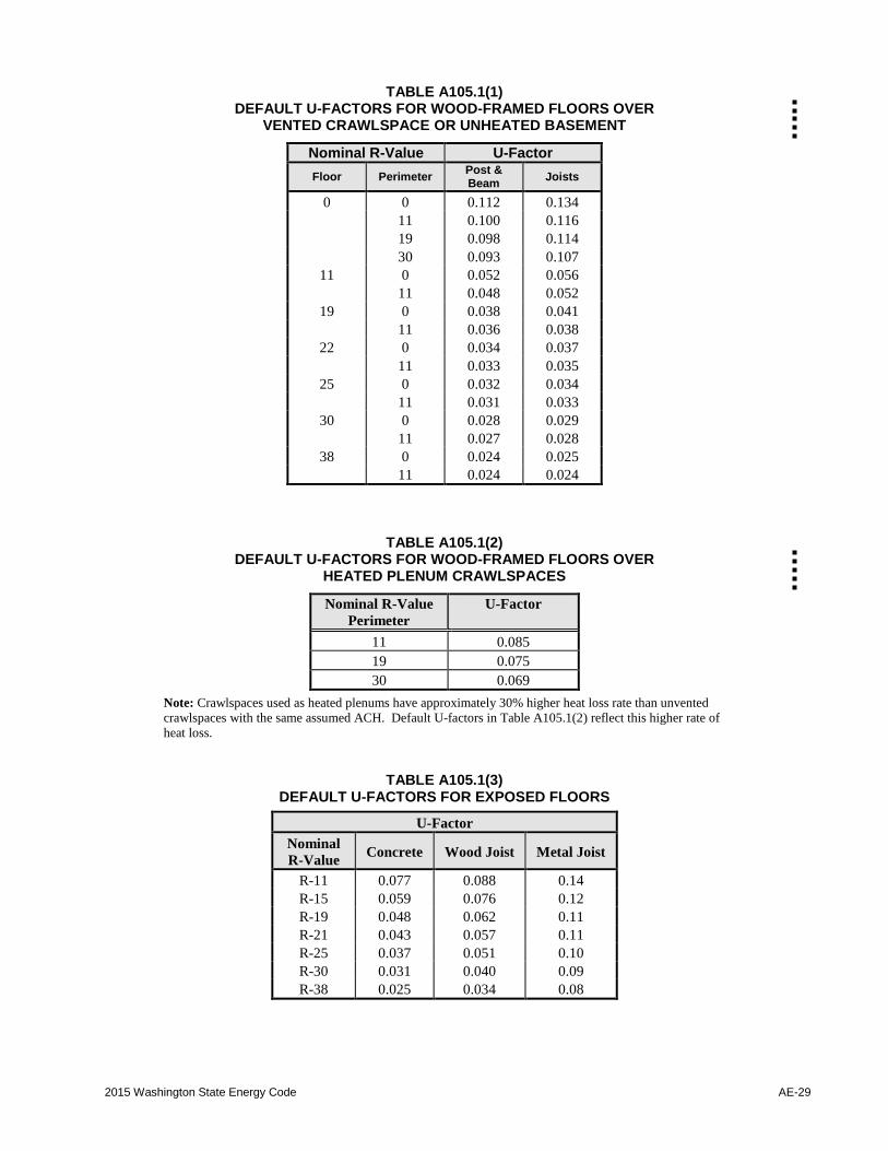
A105.1 General. Tables A105.1(1), A105.1(2) and
A105.1(3) list heat loss coefficients for floors over
unconditioned spaces in units of Btu/h ft2 °F.
They are derived from procedures listed in the
ASHRAE Fundamentals Handbook, assuming an
average outdoor temperature of 45°F, an average
indoor temperature of 65°F and a crawlspace area of
1350 ft2 and 100 feet of perimeter. The crawlspace is
assumed to be 2.5 feet high, with 24 inches below
grade and 6 inches above grade.
2015 Washington State Energy Code AE-29
TABLE A105.1(1) DEFAULT U-FACTORS FOR WOOD-FRAMED FLOORS OVER
VENTED CRAWLSPACE OR UNHEATED BASEMENT
Nominal R-Value U-Factor
Floor Perimeter Post & Beam
Joists
0 0 0.112 0.134
11 0.100 0.116
19 0.098 0.114
30 0.093 0.107
11 0 0.052 0.056
11 0.048 0.052
19 0 0.038 0.041
11 0.036 0.038
22 0 0.034 0.037
11 0.033 0.035
25 0 0.032 0.034
11 0.031 0.033
30 0 0.028 0.029
11 0.027 0.028
38 0 0.024 0.025
11 0.024 0.024
TABLE A105.1(2)
DEFAULT U-FACTORS FOR WOOD-FRAMED FLOORS OVER HEATED PLENUM CRAWLSPACES
Nominal R-Value
Perimeter
U-Factor
11 0.085
19 0.075
30 0.069
Note: Crawlspaces used as heated plenums have approximately 30% higher heat loss rate than unvented
crawlspaces with the same assumed ACH. Default U-factors in Table A105.1(2) reflect this higher rate of
heat loss.
TABLE A105.1(3) DEFAULT U-FACTORS FOR EXPOSED FLOORS
U-Factor
Nominal
R-Value Concrete Wood Joist Metal Joist
R-11 0.077 0.088 0.14
R-15 0.059 0.076 0.12
R-19 0.048 0.062 0.11
R-21 0.043 0.057 0.11
R-25 0.037 0.051 0.10
R-30 0.031 0.040 0.09
R-38 0.025 0.034 0.08

AE-30 2012 Washington State Energy Code
A105.2 Crawlspace description. Four
configurations are considered: Naturally ventilated
crawlspace, mechanically vented crawlspace, heated
plenum crawlspace and exposed floor.
A105.2.1 Naturally ventilated crawlspaces. Assumed to have 3.0 air changes per hour, with at
least 1.0 ft2 of net-free ventilation in the foundation
for every 300 ft2 of crawlspace floor area. The
crawlspace is not actively heated. Floors over
unheated areas, such as garages, may only use those
values which have R-0 perimeter insulation.
A105.2.2 Mechanically ventilated crawlspaces. Assume to have 1.5 air changes per hour, with less
than 1.0 ft2 of net-free ventilation in the foundation
for every 300 ft2 of crawlspace floor area. The
crawlspace is not actively heated. Floors over
unheated basements may only use those values which
have R-0 perimeter insulation.
A105.2.3 Heated plenum crawlspaces. Assumed to
have 0.25 air changes per hour, with no foundation
vents. Heated supply air from central furnace is
blown into a crawlspace and allowed to enter the
living space unducted via holes cut into the floor.
A105.2.4 Exposed floors. Assumes no buffer space,
and a covering of 1/2 inch T1-11 on the exterior of
the cavity exposed to the outside air or rigid
insulation below a concrete floor, such as over
parking garages.
A105.3 Construction description. Floors are
assumed to be either joisted floors framed on 16 inch
centers, or post and beam on 4 foot by 8 foot squares.
Insulation is assumed to be installed under the
subflooring between the joists or beams with no
space between the insulation and the subfloor.
Insulation is assumed to be uncompressed. Exposed
floors also include concrete with continuous rigid
insulation assumed.
Perimeter insulation is assumed to extend from the
top of the rim joist to the crawlspace floor and then
inward along the ground (on top of the ground cover)
for at least 24 inches.
Floor coverings are assumed to be light carpet with
rubber pad.
SECTION A106 ON-GRADE SLAB FLOORS
A106.1 General. Table A106.1 lists heat loss
coefficients for heated on-grade slab floors, in units
of Btu/h °F per lineal foot of perimeter.
TABLE A106.1 DEFAULT F-FACTORS FOR ON-GRADE SLABS
Insulation type R-0 R-5 R-10 R-15
Unheated Slab
Uninsulated slab 0.73 -- -- --
2 ft Horizontal (No thermal break) -- 0.70 0.70 0.69
4 ft Horizontal (No thermal break) -- 0.67 0.64 0.63
2 ft Vertical -- 0.58 0.54 0.52
4 ft Vertical -- 0.54 0.48 0.45
Fully insulated slab -- -- 0.36 --
Heated Slab
Uninsulated slab 0.84 -- -- --
Fully insulated slab -- 0.74 0.55 0.44
R-5 Center (With perimeter insulation) -- -- 0.66 0.62
R-10 Center (With perimeter insulation) -- -- -- 0.51
3 ft Vertical -- -- 0.78 --
2015 Washington State Energy Code AE-31
A106.2 Component description. All on-grade slab
floors are assumed to be 6 inch concrete poured
directly onto the earth. The bottom of the slab is
assumed to be at grade line. Monolithic and floating
slabs are not differentiated.
Soil is assumed to have a conductivity of 0.75
Btu/h ft2 °F. Slabs 2 feet or more below grade
should use basement coefficients.
A106.3 Insulation description. Coefficients are
provided for the following three configurations:
1. Two foot (or four foot) vertical: Insulation is
applied directly to the slab exterior, extending
downward from the top of the slab to a depth
of 2 feet (or 4 feet) below grade.
2. Two foot (or four foot) horizontal: Insulation is applied directly to the underside
of the slab, and run horizontally from the
perimeter inward for 2 feet (or 4 feet). The
slab edge is exposed in this configuration.
Note: A horizontal installation with a
thermal break of at least R-5 at the slab
edge should use the vertical-case F-
factors.
3. Fully insulated slab: Insulation extends from
the top of the slab, along the entire perimeter,
and completely covers the area under the slab.
Thicker perimeter insulation covers the slab
edge and extends 2 feet under the slab.
SECTION A107
DEFAULT U-FACTORS FOR DOORS
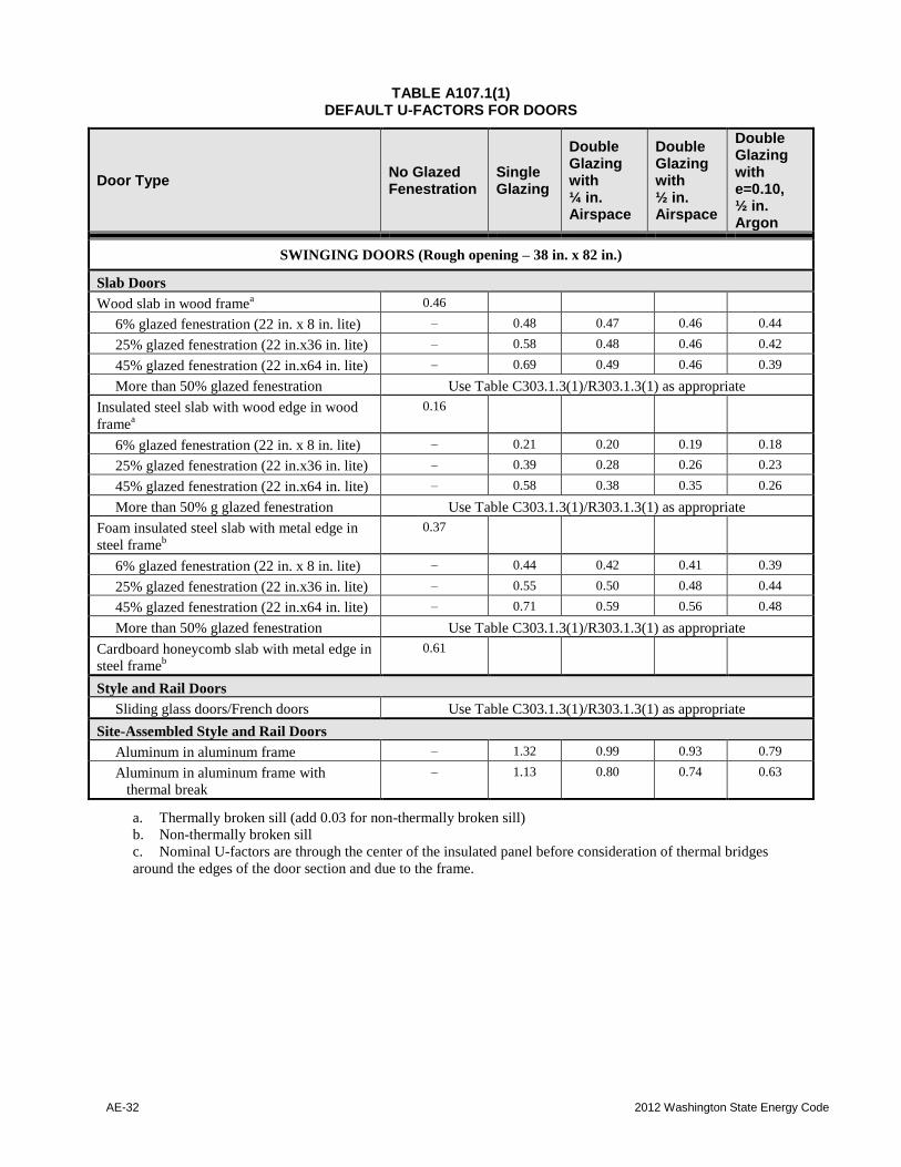
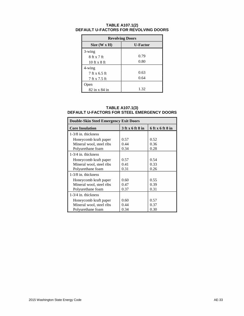
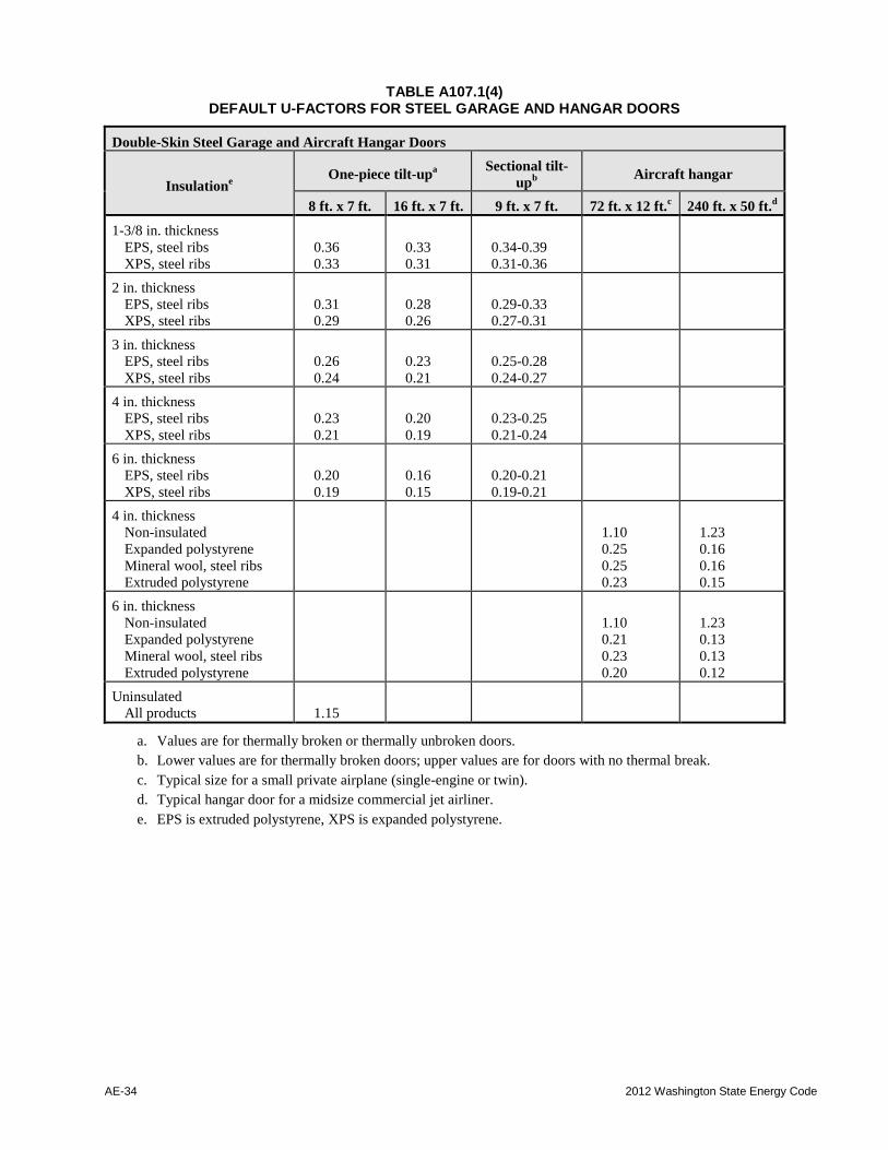
A107.1 Doors without NFRC certification. Doors
that do not have NFRC certification shall be assigned
the appropriate U-factor from Tables A107.1(1)
through A107.1(4).
AE-32 2012 Washington State Energy Code
TABLE A107.1(1) DEFAULT U-FACTORS FOR DOORS
Door Type No Glazed Fenestration
Single Glazing
Double Glazing with ¼ in. Airspace
Double Glazing with ½ in. Airspace
Double Glazing with e=0.10, ½ in. Argon
SWINGING DOORS (Rough opening – 38 in. x 82 in.)
Slab Doors
Wood slab in wood framea 0.46
6% glazed fenestration (22 in. x 8 in. lite) – 0.48 0.47 0.46 0.44
25% glazed fenestration (22 in.x36 in. lite) – 0.58 0.48 0.46 0.42
45% glazed fenestration (22 in.x64 in. lite) – 0.69 0.49 0.46 0.39
More than 50% glazed fenestration Use Table C303.1.3(1)/R303.1.3(1) as appropriate
Insulated steel slab with wood edge in wood
framea
0.16
6% glazed fenestration (22 in. x 8 in. lite) – 0.21 0.20 0.19 0.18
25% glazed fenestration (22 in.x36 in. lite) – 0.39 0.28 0.26 0.23
45% glazed fenestration (22 in.x64 in. lite) – 0.58 0.38 0.35 0.26
More than 50% g glazed fenestration Use Table C303.1.3(1)/R303.1.3(1) as appropriate
Foam insulated steel slab with metal edge in
steel frameb
0.37
6% glazed fenestration (22 in. x 8 in. lite) – 0.44 0.42 0.41 0.39
25% glazed fenestration (22 in.x36 in. lite) – 0.55 0.50 0.48 0.44
45% glazed fenestration (22 in.x64 in. lite) – 0.71 0.59 0.56 0.48
More than 50% glazed fenestration Use Table C303.1.3(1)/R303.1.3(1) as appropriate
Cardboard honeycomb slab with metal edge in
steel frameb
0.61
Style and Rail Doors
Sliding glass doors/French doors Use Table C303.1.3(1)/R303.1.3(1) as appropriate
Site-Assembled Style and Rail Doors
Aluminum in aluminum frame – 1.32 0.99 0.93 0.79
Aluminum in aluminum frame with
thermal break
– 1.13 0.80 0.74 0.63
a. Thermally broken sill (add 0.03 for non-thermally broken sill)
b. Non-thermally broken sill
c. Nominal U-factors are through the center of the insulated panel before consideration of thermal bridges
around the edges of the door section and due to the frame.
2015 Washington State Energy Code AE-33
TABLE A107.1(2) DEFAULT U-FACTORS FOR REVOLVING DOORS
Revolving Doors
Size (W x H) U-Factor
3-wing
8 ft x 7 ft 0.79
10 ft x 8 ft 0.80
4-wing
7 ft x 6.5 ft 0.63
7 ft x 7.5 ft 0.64
Open
82 in x 84 in 1.32
TABLE A107.1(3) DEFAULT U-FACTORS FOR STEEL EMERGENCY DOORS
Double-Skin Steel Emergency Exit Doors
Core Insulation 3 ft x 6 ft 8 in 6 ft x 6 ft 8 in
1-3/8 in. thickness
Honeycomb kraft paper
Mineral wool, steel ribs
Polyurethane foam
0.57
0.44
0.34
0.52
0.36
0.28
1-3/4 in. thickness
Honeycomb kraft paper
Mineral wool, steel ribs
Polyurethane foam
0.57
0.41
0.31
0.54
0.33
0.26
1-3/8 in. thickness
Honeycomb kraft paper
Mineral wool, steel ribs
Polyurethane foam
0.60
0.47
0.37
0.55
0.39
0.31
1-3/4 in. thickness
Honeycomb kraft paper
Mineral wool, steel ribs
Polyurethane foam
0.60
0.44
0.34
0.57
0.37
0.30
AE-34 2012 Washington State Energy Code
TABLE A107.1(4) DEFAULT U-FACTORS FOR STEEL GARAGE AND HANGAR DOORS
Double-Skin Steel Garage and Aircraft Hangar Doors
Insulatione
One-piece tilt-upa
Sectional tilt-
upb
Aircraft hangar
8 ft. x 7 ft. 16 ft. x 7 ft. 9 ft. x 7 ft. 72 ft. x 12 ft.c 240 ft. x 50 ft.
d
1-3/8 in. thickness
EPS, steel ribs
XPS, steel ribs
0.36
0.33
0.33
0.31
0.34-0.39
0.31-0.36
2 in. thickness
EPS, steel ribs
XPS, steel ribs
0.31
0.29
0.28
0.26
0.29-0.33
0.27-0.31
3 in. thickness
EPS, steel ribs
XPS, steel ribs
0.26
0.24
0.23
0.21
0.25-0.28
0.24-0.27
4 in. thickness
EPS, steel ribs
XPS, steel ribs
0.23
0.21
0.20
0.19
0.23-0.25
0.21-0.24
6 in. thickness
EPS, steel ribs
XPS, steel ribs
0.20
0.19
0.16
0.15
0.20-0.21
0.19-0.21
4 in. thickness
Non-insulated
Expanded polystyrene
Mineral wool, steel ribs
Extruded polystyrene
1.10
0.25
0.25
0.23
1.23
0.16
0.16
0.15
6 in. thickness
Non-insulated
Expanded polystyrene
Mineral wool, steel ribs
Extruded polystyrene
1.10
0.21
0.23
0.20
1.23
0.13
0.13
0.12
Uninsulated
All products
1.15
a. Values are for thermally broken or thermally unbroken doors.
b. Lower values are for thermally broken doors; upper values are for doors with no thermal break.
c. Typical size for a small private airplane (single-engine or twin).
d. Typical hangar door for a midsize commercial jet airliner.
e. EPS is extruded polystyrene, XPS is expanded polystyrene.
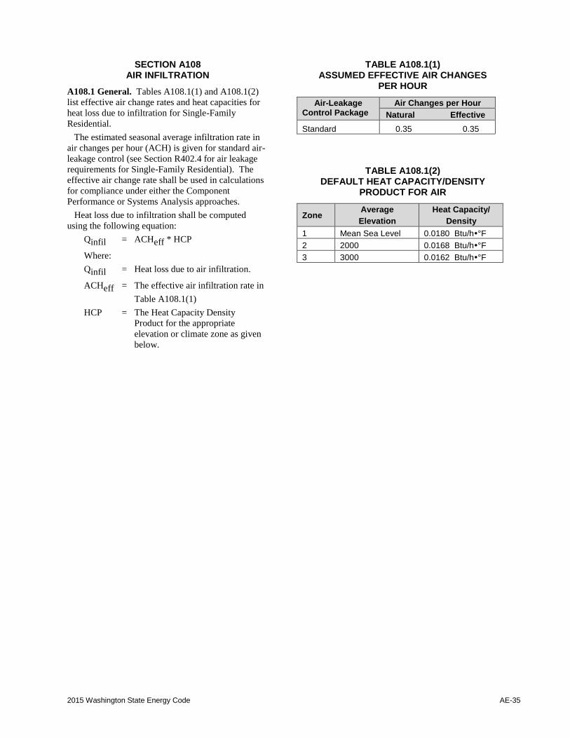
2015 Washington State Energy Code AE-35
SECTION A108 AIR INFILTRATION
A108.1 General. Tables A108.1(1) and A108.1(2)
list effective air change rates and heat capacities for
heat loss due to infiltration for Single-Family
Residential.
The estimated seasonal average infiltration rate in
air changes per hour (ACH) is given for standard air-
leakage control (see Section R402.4 for air leakage
requirements for Single-Family Residential). The
effective air change rate shall be used in calculations
for compliance under either the Component
Performance or Systems Analysis approaches.
Heat loss due to infiltration shall be computed
using the following equation:
Qinfil = ACHeff * HCP
Where:
Qinfil = Heat loss due to air infiltration.
ACHeff = The effective air infiltration rate in
Table A108.1(1)
HCP = The Heat Capacity Density
Product for the appropriate
elevation or climate zone as given
below.
TABLE A108.1(1) ASSUMED EFFECTIVE AIR CHANGES
PER HOUR
Air-Leakage Control Package
Air Changes per Hour
Natural Effective
Standard 0.35 0.35
TABLE A108.1(2) DEFAULT HEAT CAPACITY/DENSITY
PRODUCT FOR AIR
Zone Average
Elevation
Heat Capacity/
Density
1 Mean Sea Level 0.0180 Btu/h°F
2 2000 0.0168 Btu/h°F
3 3000 0.0162 Btu/h°F
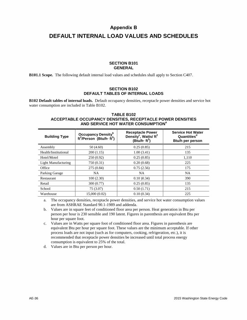
AE-36 2015 Washington State Energy Code
Appendix B
DEFAULT INTERNAL LOAD VALUES AND SCHEDULES
SECTION B101 GENERAL
B101.1 Scope. The following default internal load values and schedules shall apply to Section C407.
SECTION B102 DEFAULT TABLES OF INTERNAL LOADS
B102 Default tables of internal loads. Default occupancy densities, receptacle power densities and service hot
water consumption are included in Table B102.
TABLE B102
ACCEPTABLE OCCUPANCY DENSITIES, RECEPTACLE POWER DENSITIES AND SERVICE HOT WATER CONSUMPTION
a
Building Type Occupancy Density
b
ft2/Person (Btu/h· ft
2)
Receptacle Power Density
c, Watts/ ft
2
(Btu/h· ft2)
Service Hot Water Quantities
d
Btu/h per person
Assembly 50 (4.60) 0.25 (0.85) 215
Health/Institutional 200 (1.15) 1.00 (3.41) 135
Hotel/Motel 250 (0.92) 0.25 (0.85) 1,110
Light Manufacturing 750 (0.31) 0.20 (0.68) 225
Office 275 (0.84) 0.75 (2.56) 175
Parking Garage NA NA NA
Restaurant 100 (2.30) 0.10 )0.34) 390
Retail 300 (0.77) 0.25 (0.85) 135
School 75 (3.07) 0.50 (1.71) 215
Warehouse 15,000 (0.02) 0.10 (0.34) 225
a. The occupancy densities, receptacle power densities, and service hot water consumption values
are from ASHRAE Standard 90.1-1989 and addenda.
b. Values are in square feet of conditioned floor area per person. Heat generation in Btu per
person per hour is 230 sensible and 190 latent. Figures in parenthesis are equivalent Btu per
hour per square foot.
c. Values are in Watts per square foot of conditioned floor area. Figures in parenthesis are
equivalent Btu per hour per square foot. These values are the minimum acceptable. If other
process loads are not input (such as for computers, cooking, refrigeration, etc.), it is
recommended that receptacle power densities be increased until total process energy
consumption is equivalent to 25% of the total.
d. Values are in Btu per person per hour.
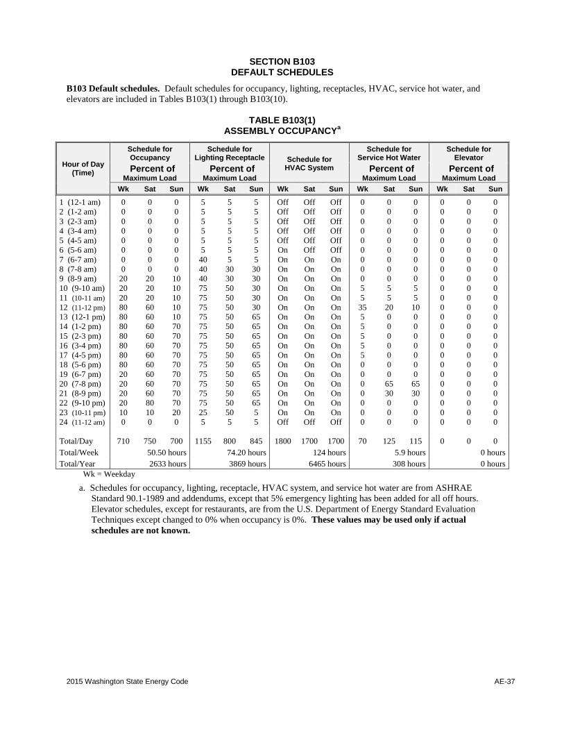
2015 Washington State Energy Code AE-37
SECTION B103 DEFAULT SCHEDULES
B103 Default schedules. Default schedules for occupancy, lighting, receptacles, HVAC, service hot water, and
elevators are included in Tables B103(1) through B103(10).
TABLE B103(1) ASSEMBLY OCCUPANCY
a
Hour of Day (Time)
Schedule for Occupancy
Schedule for Lighting Receptacle Schedule for
HVAC System
Schedule for Service Hot Water
Schedule for Elevator
Percent of Maximum Load
Percent of Maximum Load
Percent of Maximum Load
Percent of Maximum Load
Wk Sat Sun Wk Sat Sun Wk Sat Sun Wk Sat Sun Wk Sat Sun
1 (12-1 am) 0 0 0 5 5 5 Off Off Off 0 0 0 0 0 0
2 (1-2 am) 0 0 0 5 5 5 Off Off Off 0 0 0 0 0 0
3 (2-3 am) 0 0 0 5 5 5 Off Off Off 0 0 0 0 0 0
4 (3-4 am) 0 0 0 5 5 5 Off Off Off 0 0 0 0 0 0
5 (4-5 am) 0 0 0 5 5 5 Off Off Off 0 0 0 0 0 0
6 (5-6 am) 0 0 0 5 5 5 On Off Off 0 0 0 0 0 0
7 (6-7 am) 0 0 0 40 5 5 On On On 0 0 0 0 0 0
8 (7-8 am) 0 0 0 40 30 30 On On On 0 0 0 0 0 0
9 (8-9 am) 20 20 10 40 30 30 On On On 0 0 0 0 0 0
10 (9-10 am) 20 20 10 75 50 30 On On On 5 5 5 0 0 0
11 (10-11 am) 20 20 10 75 50 30 On On On 5 5 5 0 0 0
12 (11-12 pm) 80 60 10 75 50 30 On On On 35 20 10 0 0 0
13 (12-1 pm) 80 60 10 75 50 65 On On On 5 0 0 0 0 0
14 (1-2 pm) 80 60 70 75 50 65 On On On 5 0 0 0 0 0
15 (2-3 pm) 80 60 70 75 50 65 On On On 5 0 0 0 0 0
16 (3-4 pm) 80 60 70 75 50 65 On On On 5 0 0 0 0 0
17 (4-5 pm) 80 60 70 75 50 65 On On On 5 0 0 0 0 0
18 (5-6 pm) 80 60 70 75 50 65 On On On 0 0 0 0 0 0
19 (6-7 pm) 20 60 70 75 50 65 On On On 0 0 0 0 0 0
20 (7-8 pm) 20 60 70 75 50 65 On On On 0 65 65 0 0 0
21 (8-9 pm) 20 60 70 75 50 65 On On On 0 30 30 0 0 0
22 (9-10 pm) 20 80 70 75 50 65 On On On 0 0 0 0 0 0
23 (10-11 pm) 10 10 20 25 50 5 On On On 0 0 0 0 0 0
24 (11-12 am) 0 0 0 5 5 5 Off Off Off 0 0 0 0 0 0
Total/Day 710 750 700 1155 800 845 1800 1700 1700 70 125 115 0 0 0
Total/Week 50.50 hours 74.20 hours 124 hours 5.9 hours 0 hours
Total/Year 2633 hours 3869 hours 6465 hours 308 hours 0 hours
Wk = Weekday
a. Schedules for occupancy, lighting, receptacle, HVAC system, and service hot water are from ASHRAE
Standard 90.1-1989 and addendums, except that 5% emergency lighting has been added for all off hours.
Elevator schedules, except for restaurants, are from the U.S. Department of Energy Standard Evaluation
Techniques except changed to 0% when occupancy is 0%. These values may be used only if actual
schedules are not known.
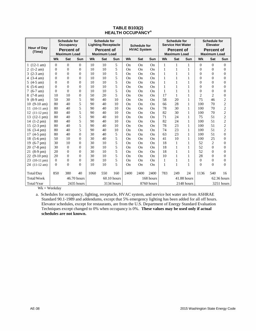
AE-38 2015 Washington State Energy Code
TABLE B103(2) HEALTH OCCUPANCY
a
Hour of Day (Time)
Schedule for Occupancy
Schedule for Lighting Receptacle Schedule for
HVAC System
Schedule for Service Hot Water
Schedule for Elevator
Percent of Maximum Load
Percent of Maximum Load
Percent of Maximum Load
Percent of Maximum Load
Wk Sat Sun Wk Sat Sun Wk Sat Sun Wk Sat Sun Wk Sat Sun
1 (12-1 am) 0 0 0 10 10 5 On On On 1 1 1 0 0 0
2 (1-2 am) 0 0 0 10 10 5 On On On 1 1 1 0 0 0
3 (2-3 am) 0 0 0 10 10 5 On On On 1 1 1 0 0 0
4 (3-4 am) 0 0 0 10 10 5 On On On 1 1 1 0 0 0
5 (4-5 am) 0 0 0 10 10 5 On On On 1 1 1 0 0 0
6 (5-6 am) 0 0 0 10 10 5 On On On 1 1 1 0 0 0
7 (6-7 am) 0 0 0 10 10 5 On On On 1 1 1 0 0 0
8 (7-8 am) 10 10 0 50 20 5 On On On 17 1 1 2 2 0
9 (8-9 am) 50 30 5 90 40 10 On On On 58 20 1 75 46 2
10 (9-10 am) 80 40 5 90 40 10 On On On 66 28 1 100 70 2
11 (10-11 am) 80 40 5 90 40 10 On On On 78 30 1 100 70 2
12 (11-12 pm) 80 40 5 90 40 10 On On On 82 30 1 100 70 2
13 (12-1 pm) 80 40 5 90 40 10 On On On 71 24 1 75 51 2
14 (1-2 pm) 80 40 5 90 40 10 On On On 82 24 1 100 51 2
15 (2-3 pm) 80 40 5 90 40 10 On On On 78 23 1 100 51 2
16 (3-4 pm) 80 40 5 90 40 10 On On On 74 23 1 100 51 2
17 (4-5 pm) 80 40 0 30 40 5 On On On 63 23 1 100 51 0
18 (5-6 pm) 50 10 0 30 40 5 On On On 41 10 1 100 25 0
19 (6-7 pm) 30 10 0 30 10 5 On On On 18 1 1 52 2 0
20 (7-8 pm) 30 0 0 30 10 5 On On On 18 1 1 52 0 0
21 (8-9 pm) 20 0 0 30 10 5 On On On 18 1 1 52 0 0
22 (9-10 pm) 20 0 0 30 10 5 On On On 10 1 1 28 0 0
23 (10-11 pm) 0 0 0 30 10 5 On On On 1 1 1 0 0 0
24 (11-12 am) 0 0 0 10 10 5 On On On 1 1 1 0 0 0
Total/Day 850 380 40 1060 550 160 2400 2400 2400 783 249 24 1136 540 16
Total/Week 46.70 hours 60.10 hours 168 hours 41.88 hours 62.36 hours
Total/Year 2435 hours 3134 hours 8760 hours 2148 hours 3251 hours
Wk = Weekday
a. Schedules for occupancy, lighting, receptacle, HVAC system, and service hot water are from ASHRAE
Standard 90.1-1989 and addendums, except that 5% emergency lighting has been added for all off hours.
Elevator schedules, except for restaurants, are from the U.S. Department of Energy Standard Evaluation
Techniques except changed to 0% when occupancy is 0%. These values may be used only if actual
schedules are not known.
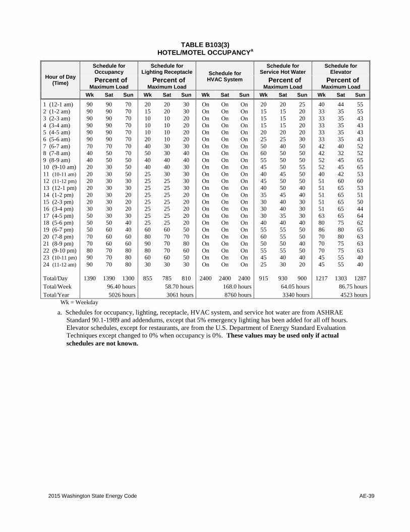
2015 Washington State Energy Code AE-39
TABLE B103(3) HOTEL/MOTEL OCCUPANCY
a
Hour of Day (Time)
Schedule for Occupancy
Schedule for Lighting Receptacle Schedule for
HVAC System
Schedule for Service Hot Water
Schedule for Elevator
Percent of Maximum Load
Percent of Maximum Load
Percent of Maximum Load
Percent of Maximum Load
Wk Sat Sun Wk Sat Sun Wk Sat Sun Wk Sat Sun Wk Sat Sun
1 (12-1 am) 90 90 70 20 20 30 On On On 20 20 25 40 44 55
2 (1-2 am) 90 90 70 15 20 30 On On On 15 15 20 33 35 55
3 (2-3 am) 90 90 70 10 10 20 On On On 15 15 20 33 35 43
4 (3-4 am) 90 90 70 10 10 20 On On On 15 15 20 33 35 43
5 (4-5 am) 90 90 70 10 10 20 On On On 20 20 20 33 35 43
6 (5-6 am) 90 90 70 20 10 20 On On On 25 25 30 33 35 43
7 (6-7 am) 70 70 70 40 30 30 On On On 50 40 50 42 40 52
8 (7-8 am) 40 50 70 50 30 40 On On On 60 50 50 42 32 52
9 (8-9 am) 40 50 50 40 40 40 On On On 55 50 50 52 45 65
10 (9-10 am) 20 30 50 40 40 30 On On On 45 50 55 52 45 65
11 (10-11 am) 20 30 50 25 30 30 On On On 40 45 50 40 42 53
12 (11-12 pm) 20 30 30 25 25 30 On On On 45 50 50 51 60 60
13 (12-1 pm) 20 30 30 25 25 30 On On On 40 50 40 51 65 53
14 (1-2 pm) 20 30 20 25 25 20 On On On 35 45 40 51 65 51
15 (2-3 pm) 20 30 20 25 25 20 On On On 30 40 30 51 65 50
16 (3-4 pm) 30 30 20 25 25 20 On On On 30 40 30 51 65 44
17 (4-5 pm) 50 30 30 25 25 20 On On On 30 35 30 63 65 64
18 (5-6 pm) 50 50 40 25 25 20 On On On 40 40 40 80 75 62
19 (6-7 pm) 50 60 40 60 60 50 On On On 55 55 50 86 80 65
20 (7-8 pm) 70 60 60 80 70 70 On On On 60 55 50 70 80 63
21 (8-9 pm) 70 60 60 90 70 80 On On On 50 50 40 70 75 63
22 (9-10 pm) 80 70 80 80 70 60 On On On 55 55 50 70 75 63
23 (10-11 pm) 90 70 80 60 60 50 On On On 45 40 40 45 55 40
24 (11-12 am) 90 70 80 30 30 30 On On On 25 30 20 45 55 40
Total/Day 1390 1390 1300 855 785 810 2400 2400 2400 915 930 900 1217 1303 1287
Total/Week 96.40 hours 58.70 hours 168.0 hours 64.05 hours 86.75 hours
Total/Year 5026 hours 3061 hours 8760 hours 3340 hours 4523 hours
Wk = Weekday
a. Schedules for occupancy, lighting, receptacle, HVAC system, and service hot water are from ASHRAE
Standard 90.1-1989 and addendums, except that 5% emergency lighting has been added for all off hours.
Elevator schedules, except for restaurants, are from the U.S. Department of Energy Standard Evaluation
Techniques except changed to 0% when occupancy is 0%. These values may be used only if actual
schedules are not known.

AE-40 2015 Washington State Energy Code
TABLE B103(4) LIGHT MANUFACTURING OCCUPANCY
a
Hour of Day (Time)
Schedule for Occupancy
Schedule for Lighting Receptacle Schedule for
HVAC System
Schedule for Service Hot Water
Schedule for Elevator
Percent of Maximum Load
Percent of Maximum Load
Percent of Maximum Load
Percent of Maximum Load
Wk Sat Sun Wk Sat Sun Wk Sat Sun Wk Sat Sun Wk Sat Sun
1 (12-1 am) 0 0 0 5 5 5 Off Off Off 5 5 4 0 0 0
2 (1-2 am) 0 0 0 5 5 5 Off Off Off 5 5 4 0 0 0
3 (2-3 am) 0 0 0 5 5 5 Off Off Off 5 5 4 0 0 0
4 (3-4 am) 0 0 0 5 5 5 Off Off Off 5 5 4 0 0 0
5 (4-5 am) 0 0 0 5 5 5 Off Off Off 5 5 4 0 0 0
6 (5-6 am) 0 0 0 10 5 5 Off Off Off 8 8 7 0 0 0
7 (6-7 am) 10 10 5 10 10 5 On On Off 7 7 4 0 0 0
8 (7-8 am) 20 10 5 30 10 5 On On Off 19 11 4 35 16 0
9 (8-9 am) 95 30 5 90 30 5 On On Off 35 15 4 69 14 0
10 (9-10 am) 95 30 5 90 30 5 On On Off 38 21 4 43 21 0
11 (10-11 am) 95 30 5 90 30 5 On On Off 39 19 4 37 18 0
12 (11-12 pm) 95 30 5 90 30 5 On On Off 47 23 6 43 25 0
13 (12-1 pm) 50 10 5 80 15 5 On On Off 57 20 6 58 21 0
14 (1-2 pm) 95 10 5 90 15 5 On On Off 54 19 9 48 13 0
15 (2-3 pm) 95 10 5 90 15 5 On On Off 34 15 6 37 8 0
16 (3-4 pm) 95 10 5 90 15 5 On On Off 33 12 4 37 4 0
17 (4-5 pm) 95 10 5 90 15 5 On On Off 44 14 4 46 5 0
18 (5-6 pm) 30 5 5 50 5 5 On On Off 26 7 4 62 6 0
19 (6-7 pm) 10 5 0 30 5 5 On Off Off 21 7 4 20 0 0
20 (7-8 pm) 10 0 0 30 5 5 On Off Off 15 7 4 12 0 0
21 (8-9 pm) 10 0 0 20 5 5 On Off Off 17 7 4 4 0 0
22 (9-10 pm) 10 0 0 20 5 5 On Off Off 8 9 7 4 0 0
23 (10-11 pm) 5 0 0 10 5 5 Off Off Off 5 5 4 0 0 0
24 (11-12 am) 5 0 0 5 5 5 Off Off Off 5 5 4 0 0 0
Total/Day 920 200 60 1040 280 120 1600 1200 0 537 256 113 555 151 0
Total/Week 48.60 hours 56.00 hours 92.00 hours 30.54 hours 29.26 hours
Total/Year 2534 hours 2920 hours 4797 hours 1592 hours 1526 hours
Wk = Weekday
a. Schedules for occupancy, lighting, receptacle, HVAC system, and service hot water are from ASHRAE
Standard 90.1-1989 and addendums, except that 5% emergency lighting has been added for all off hours.
Elevator schedules, except for restaurants, are from the U.S. Department of Energy Standard Evaluation
Techniques except changed to 0% when occupancy is 0%. These values may be used only if actual
schedules are not known.
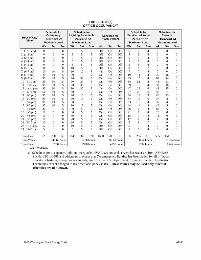
2015 Washington State Energy Code AE-41
TABLE B103(5) OFFICE OCCUPANCY
a
Hour of Day (Time)
Schedule for Occupancy
Schedule for Lighting Receptacle Schedule for
HVAC System
Schedule for Service Hot Water
Schedule for Elevator
Percent of Maximum Load
Percent of Maximum Load
Percent of Maximum Load
Percent of Maximum Load
Wk Sat Sun Wk Sat Sun Wk Sat Sun Wk Sat Sun Wk Sat Sun
1 (12-1 am) 0 0 0 5 5 5 Off Off Off 5 5 4 0 0 0
2 (1-2 am) 0 0 0 5 5 5 Off Off Off 5 5 4 0 0 0
3 (2-3 am) 0 0 0 5 5 5 Off Off Off 5 5 4 0 0 0
4 (3-4 am) 0 0 0 5 5 5 Off Off Off 5 5 4 0 0 0
5 (4-5 am) 0 0 0 5 5 5 Off Off Off 5 5 4 0 0 0
6 (5-6 am) 0 0 0 10 5 5 Off Off Off 8 8 7 0 0 0
7 (6-7 am) 10 10 5 10 10 5 On On Off 7 7 4 0 0 0
8 (7-8 am) 20 10 5 30 10 5 On On Off 19 11 4 35 16 0
9 (8-9 am) 95 30 5 90 30 5 On On Off 35 15 4 69 14 0
10 (9-10 am) 95 30 5 90 30 5 On On Off 38 21 4 43 21 0
11 (10-11 am) 95 30 5 90 30 5 On On Off 39 19 4 37 18 0
12 (11-12 pm) 95 30 5 90 30 5 On On Off 47 23 6 43 25 0
13 (12-1 pm) 50 10 5 80 15 5 On On Off 57 20 6 58 21 0
14 (1-2 pm) 95 10 5 90 15 5 On On Off 54 19 9 48 13 0
15 (2-3 pm) 95 10 5 90 15 5 On On Off 34 15 6 37 8 0
16 (3-4 pm) 95 10 5 90 15 5 On On Off 33 12 4 37 4 0
17 (4-5 pm) 95 10 5 90 15 5 On On Off 44 14 4 46 5 0
18 (5-6 pm) 30 5 5 50 5 5 On On Off 26 7 4 62 6 0
19 (6-7 pm) 10 5 0 30 5 5 On Off Off 21 7 4 20 0 0
20 (7-8 pm) 10 0 0 30 5 5 On Off Off 15 7 4 12 0 0
21 (8-9 pm) 10 0 0 20 5 5 On Off Off 17 7 4 4 0 0
22 (9-10 pm) 10 0 0 20 5 5 On Off Off 8 9 7 4 0 0
23 (10-11 pm) 5 0 0 10 5 5 Off Off Off 5 5 4 0 0 0
24 (11-12 am) 5 0 0 5 5 5 Off Off Off 5 5 4 0 0 0
Total/Day 920 200 60 1040 280 120 1600 1200 0 537 256 113 555 151 0
Total/Week 48.60 hours 56.00 hours 92.00 hours 30.54 hours 29.26 hours
Total/Year 2534 hours 2920 hours 4797 hours 1592 hours 1526 hours
Wk = Weekday
a. Schedules for occupancy, lighting, receptacle, HVAC system, and service hot water are from ASHRAE
Standard 90.1-1989 and addendums, except that 5% emergency lighting has been added for all off hours.
Elevator schedules, except for restaurants, are from the U.S. Department of Energy Standard Evaluation
Techniques except changed to 0% when occupancy is 0%. These values may be used only if actual
schedules are not known.
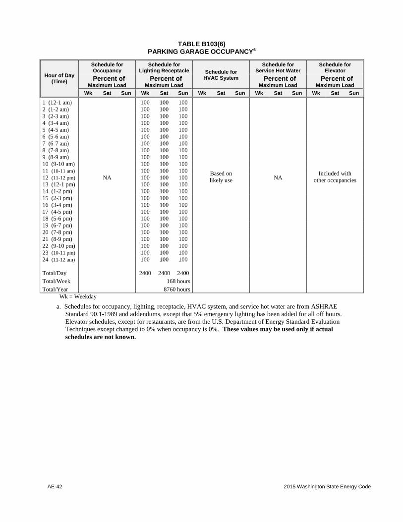
AE-42 2015 Washington State Energy Code
TABLE B103(6) PARKING GARAGE OCCUPANCY
a
Hour of Day (Time)
Schedule for Occupancy
Schedule for Lighting Receptacle Schedule for
HVAC System
Schedule for Service Hot Water
Schedule for Elevator
Percent of Maximum Load
Percent of Maximum Load
Percent of Maximum Load
Percent of Maximum Load
Wk Sat Sun Wk Sat Sun Wk Sat Sun Wk Sat Sun Wk Sat Sun
1 (12-1 am) 100 100 100
2 (1-2 am) 100 100 100
3 (2-3 am) 100 100 100
4 (3-4 am) 100 100 100
5 (4-5 am) 100 100 100
6 (5-6 am) 100 100 100
7 (6-7 am) 100 100 100
8 (7-8 am) 100 100 100
9 (8-9 am) 100 100 100
10 (9-10 am) 100 100 100
11 (10-11 am) 100 100 100 Based on
likely use
Included with
other occupancies 12 (11-12 pm) NA 100 100 100 NA
13 (12-1 pm) 100 100 100
14 (1-2 pm) 100 100 100
15 (2-3 pm) 100 100 100
16 (3-4 pm) 100 100 100
17 (4-5 pm) 100 100 100
18 (5-6 pm) 100 100 100
19 (6-7 pm) 100 100 100
20 (7-8 pm) 100 100 100
21 (8-9 pm) 100 100 100
22 (9-10 pm) 100 100 100
23 (10-11 pm) 100 100 100
24 (11-12 am) 100 100 100
Total/Day 2400 2400 2400
Total/Week 168 hours
Total/Year 8760 hours
Wk = Weekday
a. Schedules for occupancy, lighting, receptacle, HVAC system, and service hot water are from ASHRAE
Standard 90.1-1989 and addendums, except that 5% emergency lighting has been added for all off hours.
Elevator schedules, except for restaurants, are from the U.S. Department of Energy Standard Evaluation
Techniques except changed to 0% when occupancy is 0%. These values may be used only if actual
schedules are not known.

2015 Washington State Energy Code AE-43
TABLE B103(7) RESTAURANT OCCUPANCY
a
Hour of Day (Time)
Schedule for Occupancy
Schedule for Lighting Receptacle Schedule for
HVAC System
Schedule for Service Hot Water
Schedule for Elevator
Percent of Maximum Load
Percent of Maximum Load
Percent of Maximum Load
Percent of Maximum Load
Wk Sat Sun Wk Sat Sun Wk Sat Sun Wk Sat Sun Wk Sat Sun
1 (12-1 am) 15 30 20 15 20 20 On On On 20 20 25 0 0 0
2 (1-2 am) 15 25 20 15 15 15 On On On 15 15 20 0 0 0
3 (2-3 am) 5 5 5 15 15 15 On On On 15 15 20 0 0 0
4 (3-4 am) 0 0 0 15 15 15 Off Off Off 0 0 0 0 0 0
5 (4-5 am) 0 0 0 15 15 15 Off Off Off 0 0 0 0 0 0
6 (5-6 am) 0 0 0 20 15 15 Off Off Off 0 0 0 0 0 0
7 (6-7 am) 0 0 0 40 30 30 Off Off Off 0 0 0 0 0 0
8 (7-8 am) 5 0 0 40 30 30 On Off Off 60 0 0 0 0 0
9 (8-9 am) 5 0 0 60 60 50 On Off Off 55 0 0 0 0 0
10 (9-10 am) 5 5 0 60 60 50 On On Off 45 50 0 0 0 0
11 (10-11 am) 20 20 10 90 80 70 On On On 40 45 50 0 0 0
12 (11-12 pm) 50 45 20 90 80 70 On On On 45 50 50 0 0 0
13 (12-1 pm) 80 50 25 90 80 70 On On On 40 50 40 0 0 0
14 (1-2 pm) 70 50 25 90 80 70 On On On 35 45 40 0 0 0
15 (2-3 pm) 40 35 15 90 80 70 On On On 30 40 30 0 0 0
16 (3-4 pm) 20 30 20 90 80 70 On On On 30 40 30 0 0 0
17 (4-5 pm) 25 30 25 90 80 60 On On On 30 35 30 0 0 0
18 (5-6 pm) 50 30 35 90 90 60 On On On 40 40 40 0 0 0
19 (6-7 pm) 80 70 55 90 90 60 On On On 55 55 50 0 0 0
20 (7-8 pm) 80 90 65 90 90 60 On On On 60 55 50 0 0 0
21 (8-9 pm) 80 70 70 90 90 60 On On On 50 50 40 0 0 0
22 (9-10 pm) 50 65 35 90 90 60 On On On 55 55 50 0 0 0
23 (10-11 pm) 35 55 20 50 50 50 On On On 45 40 40 0 0 0
24 (11-12 am) 20 35 20 30 30 30 On On On 25 30 20 0 0 0
Total/Day 750 740 485 1455 1365 1115 2000 1800 1700 790 730 625 0 0 0
Total/Week 49.75 hours 97.55 hours 135 hours 53.05 hours 0 hours
Total/Year 2594 hours 5086 hours 7039 hours 2766 hours 0 hours
Wk = Weekday
a. Schedules for occupancy, lighting, receptacle, HVAC system, and service hot water are from ASHRAE
Standard 90.1-1989 and addendums, except that 5% emergency lighting has been added for all off hours.
Elevator schedules, except for restaurants, are from the U.S. Department of Energy Standard Evaluation
Techniques except changed to 0% when occupancy is 0%. These values may be used only if actual
schedules are not known.
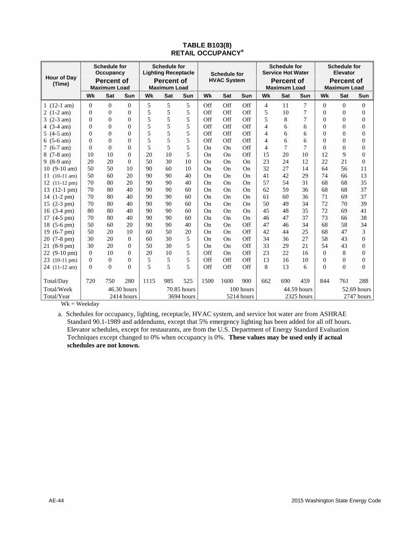
AE-44 2015 Washington State Energy Code
TABLE B103(8) RETAIL OCCUPANCY
a
Hour of Day (Time)
Schedule for Occupancy
Schedule for Lighting Receptacle Schedule for
HVAC System
Schedule for Service Hot Water
Schedule for Elevator
Percent of Maximum Load
Percent of Maximum Load
Percent of Maximum Load
Percent of Maximum Load
Wk Sat Sun Wk Sat Sun Wk Sat Sun Wk Sat Sun Wk Sat Sun
1 (12-1 am) 0 0 0 5 5 5 Off Off Off 4 11 7 0 0 0
2 (1-2 am) 0 0 0 5 5 5 Off Off Off 5 10 7 0 0 0
3 (2-3 am) 0 0 0 5 5 5 Off Off Off 5 8 7 0 0 0
4 (3-4 am) 0 0 0 5 5 5 Off Off Off 4 6 6 0 0 0
5 (4-5 am) 0 0 0 5 5 5 Off Off Off 4 6 6 0 0 0
6 (5-6 am) 0 0 0 5 5 5 Off Off Off 4 6 6 0 0 0
7 (6-7 am) 0 0 0 5 5 5 On On Off 4 7 7 0 0 0
8 (7-8 am) 10 10 0 20 10 5 On On Off 15 20 10 12 9 0
9 (8-9 am) 20 20 0 50 30 10 On On On 23 24 12 22 21 0
10 (9-10 am) 50 50 10 90 60 10 On On On 32 27 14 64 56 11
11 (10-11 am) 50 60 20 90 90 40 On On On 41 42 29 74 66 13
12 (11-12 pm) 70 80 20 90 90 40 On On On 57 54 31 68 68 35
13 (12-1 pm) 70 80 40 90 90 60 On On On 62 59 36 68 68 37
14 (1-2 pm) 70 80 40 90 90 60 On On On 61 60 36 71 69 37
15 (2-3 pm) 70 80 40 90 90 60 On On On 50 49 34 72 70 39
16 (3-4 pm) 80 80 40 90 90 60 On On On 45 48 35 72 69 41
17 (4-5 pm) 70 80 40 90 90 60 On On On 46 47 37 73 66 38
18 (5-6 pm) 50 60 20 90 90 40 On On Off 47 46 34 68 58 34
19 (6-7 pm) 50 20 10 60 50 20 On On Off 42 44 25 68 47 3
20 (7-8 pm) 30 20 0 60 30 5 On On Off 34 36 27 58 43 0
21 (8-9 pm) 30 20 0 50 30 5 On On Off 33 29 21 54 43 0
22 (9-10 pm) 0 10 0 20 10 5 Off On Off 23 22 16 0 8 0
23 (10-11 pm) 0 0 0 5 5 5 Off Off Off 13 16 10 0 0 0
24 (11-12 am) 0 0 0 5 5 5 Off Off Off 8 13 6 0 0 0
Total/Day 720 750 280 1115 985 525 1500 1600 900 662 690 459 844 761 288
Total/Week 46.30 hours 70.85 hours 100 hours 44.59 hours 52.69 hours
Total/Year 2414 hours 3694 hours 5214 hours 2325 hours 2747 hours
Wk = Weekday
a. Schedules for occupancy, lighting, receptacle, HVAC system, and service hot water are from ASHRAE
Standard 90.1-1989 and addendums, except that 5% emergency lighting has been added for all off hours.
Elevator schedules, except for restaurants, are from the U.S. Department of Energy Standard Evaluation
Techniques except changed to 0% when occupancy is 0%. These values may be used only if actual
schedules are not known.

2015 Washington State Energy Code AE-45
TABLE B103(9) SCHOOL OCCUPANCY
a
Hour of Day (Time)
Schedule for Occupancy
Schedule for Lighting Receptacle Schedule for
HVAC System
Schedule for Service Hot Water
Schedule for Elevator
Percent of Maximum Load
Percent of Maximum Load
Percent of Maximum Load
Percent of Maximum Load
Wk Sat Sun Wk Sat Sun Wk Sat Sun Wk Sat Sun Wk Sat Sun
1 (12-1 am) 0 0 0 5 5 5 Off Off Off 5 3 3 0 0 0
2 (1-2 am) 0 0 0 5 5 5 Off Off Off 5 3 3 0 0 0
3 (2-3 am) 0 0 0 5 5 5 Off Off Off 5 3 3 0 0 0
4 (3-4 am) 0 0 0 5 5 5 Off Off Off 5 3 3 0 0 0
5 (4-5 am) 0 0 0 5 5 5 Off Off Off 5 3 3 0 0 0
6 (5-6 am) 0 0 0 5 5 5 Off Off Off 5 3 3 0 0 0
7 (6-7 am) 0 0 0 5 5 5 Off Off Off 5 3 3 0 0 0
8 (7-8 am) 5 0 0 30 5 5 On Off Off 10 3 3 0 0 0
9 (8-9 am) 75 10 0 85 15 5 On On Off 34 3 5 30 0 0
10 (9-10 am) 90 10 0 95 15 5 On On Off 60 5 5 30 0 0
11 (10-11 am) 90 10 0 95 15 5 On On Off 63 5 5 30 0 0
12 (11-12 pm) 80 10 0 95 15 5 On On Off 72 5 5 30 0 0
13 (12-1 pm) 80 10 0 80 15 5 On On Off 79 5 5 30 0 0
14 (1-2 pm) 80 0 0 80 5 5 On Off Off 83 3 5 30 0 0
15 (2-3 pm) 80 0 0 80 5 5 On Off Off 61 3 3 30 0 0
16 (3-4 pm) 45 0 0 70 5 5 On Off Off 65 3 3 15 0 0
17 (4-5 pm) 15 0 0 50 5 5 On Off Off 10 3 3 0 0 0
18 (5-6 pm) 5 0 0 50 5 5 On Off Off 10 3 3 0 0 0
19 (6-7 pm) 15 0 0 35 5 5 On Off Off 19 3 3 0 0 0
20 (7-8 pm) 20 0 0 35 5 5 On Off Off 25 3 3 0 0 0
21 (8-9 pm) 20 0 0 35 5 5 On Off Off 22 3 3 0 0 0
22 (9-10 pm) 10 0 0 30 5 5 On Off Off 22 3 3 0 0 0
23 (10-11 pm) 0 0 0 5 5 5 Off Off Off 12 3 3 0 0 0
24 (11-12 am) 0 0 0 5 5 5 Off Off Off 9 3 3 0 0 0
Total/Day 710 50 0 990 170 120 1500 500 0 691 80 84 285 0 0
Total/Week 36.00 hours 52.40 hours 80.00 hours 36.19 hours 14.25 hours
Total/Year 1877 hours 2732 hours 4171 hours 1887 hours 743 hours
Wk = Weekday
a. Schedules for occupancy, lighting, receptacle, HVAC system, and service hot water are from ASHRAE
Standard 90.1-1989 and addendums, except that 5% emergency lighting has been added for all off hours.
Elevator schedules, except for restaurants, are from the U.S. Department of Energy Standard Evaluation
Techniques except changed to 0% when occupancy is 0%. These values may be used only if actual
schedules are not known.
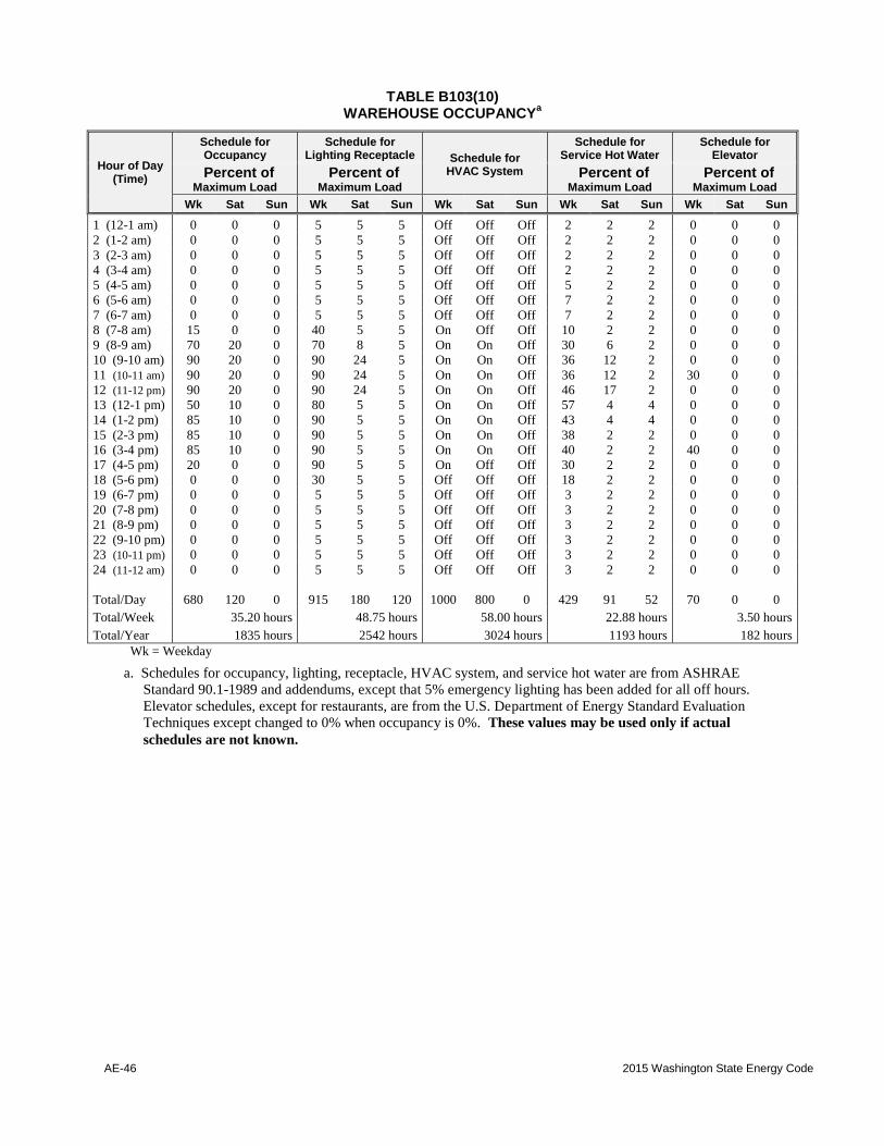
AE-46 2015 Washington State Energy Code
TABLE B103(10) WAREHOUSE OCCUPANCY
a
Hour of Day (Time)
Schedule for Occupancy
Schedule for Lighting Receptacle Schedule for
HVAC System
Schedule for Service Hot Water
Schedule for Elevator
Percent of Maximum Load
Percent of Maximum Load
Percent of Maximum Load
Percent of Maximum Load
Wk Sat Sun Wk Sat Sun Wk Sat Sun Wk Sat Sun Wk Sat Sun
1 (12-1 am) 0 0 0 5 5 5 Off Off Off 2 2 2 0 0 0
2 (1-2 am) 0 0 0 5 5 5 Off Off Off 2 2 2 0 0 0
3 (2-3 am) 0 0 0 5 5 5 Off Off Off 2 2 2 0 0 0
4 (3-4 am) 0 0 0 5 5 5 Off Off Off 2 2 2 0 0 0
5 (4-5 am) 0 0 0 5 5 5 Off Off Off 5 2 2 0 0 0
6 (5-6 am) 0 0 0 5 5 5 Off Off Off 7 2 2 0 0 0
7 (6-7 am) 0 0 0 5 5 5 Off Off Off 7 2 2 0 0 0
8 (7-8 am) 15 0 0 40 5 5 On Off Off 10 2 2 0 0 0
9 (8-9 am) 70 20 0 70 8 5 On On Off 30 6 2 0 0 0
10 (9-10 am) 90 20 0 90 24 5 On On Off 36 12 2 0 0 0
11 (10-11 am) 90 20 0 90 24 5 On On Off 36 12 2 30 0 0
12 (11-12 pm) 90 20 0 90 24 5 On On Off 46 17 2 0 0 0
13 (12-1 pm) 50 10 0 80 5 5 On On Off 57 4 4 0 0 0
14 (1-2 pm) 85 10 0 90 5 5 On On Off 43 4 4 0 0 0
15 (2-3 pm) 85 10 0 90 5 5 On On Off 38 2 2 0 0 0
16 (3-4 pm) 85 10 0 90 5 5 On On Off 40 2 2 40 0 0
17 (4-5 pm) 20 0 0 90 5 5 On Off Off 30 2 2 0 0 0
18 (5-6 pm) 0 0 0 30 5 5 Off Off Off 18 2 2 0 0 0
19 (6-7 pm) 0 0 0 5 5 5 Off Off Off 3 2 2 0 0 0
20 (7-8 pm) 0 0 0 5 5 5 Off Off Off 3 2 2 0 0 0
21 (8-9 pm) 0 0 0 5 5 5 Off Off Off 3 2 2 0 0 0
22 (9-10 pm) 0 0 0 5 5 5 Off Off Off 3 2 2 0 0 0
23 (10-11 pm) 0 0 0 5 5 5 Off Off Off 3 2 2 0 0 0
24 (11-12 am) 0 0 0 5 5 5 Off Off Off 3 2 2 0 0 0
Total/Day 680 120 0 915 180 120 1000 800 0 429 91 52 70 0 0
Total/Week 35.20 hours 48.75 hours 58.00 hours 22.88 hours 3.50 hours
Total/Year 1835 hours 2542 hours 3024 hours 1193 hours 182 hours
Wk = Weekday
a. Schedules for occupancy, lighting, receptacle, HVAC system, and service hot water are from ASHRAE
Standard 90.1-1989 and addendums, except that 5% emergency lighting has been added for all off hours.
Elevator schedules, except for restaurants, are from the U.S. Department of Energy Standard Evaluation
Techniques except changed to 0% when occupancy is 0%. These values may be used only if actual
schedules are not known.
2015 Washington State Energy Code AE-47
(This page left intentionally blank)
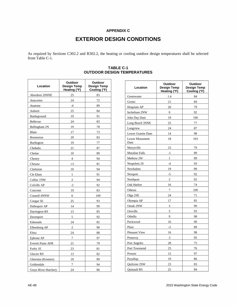
AE-48 2015 Washington State Energy Code
APPENDIX C
EXTERIOR DESIGN CONDITIONS
As required by Sections C302.2 and R302.2, the heating or cooling outdoor design temperatures shall be selected
from Table C-1.
TABLE C-1
OUTDOOR DESIGN TEMPERATURES
Location Outdoor
Design Temp Heating (°F)
Outdoor Design Temp Cooling (°F)
Aberdeen 20NNE 25 83
Anacortes 24 72
Anatone -4 89
Auburn 25 84
Battleground 19 91
Bellevue 24 83
Bellingham 2N 19 78
Blain 17 73
Bremerton 29 83
Burlington 19 77
Chehalis 21 87
Chelan 10 89
Cheney 4 94
Chesaw -11 81
Clarkston 10 94
Cle Elum 1 91
Colfax 1NW 2 94
Colville AP -2 92
Concrete 19 83
Connell 4NNW 6 100
Cougar 5E 25 93
Dallesport AP 14 99
Darrington RS 13 85
Davenport 5 92
Edmonds 24 82
Ellensburg AP 2 90
Elma 24 88
Ephrata AP 7 97
Everett Paine AFB 21 79
Forks 1E 23 81
Glacier RS 13 82
Glenoma (Kosmos) 18 89
Goldendale 7 94
Grays River Hatchery 24 86
Location Outdoor
Design Temp Heating (°F)
Outdoor Design Temp Cooling (°F)
Greenwater 1.4 84
Grotto 21 84
Hoquiam AP 26 79
Inchelium 2NW 0 92
John Day Dam 19 100
Long Beach 3NNE 25 77
Longview 24 87
Lower Granite Dam 14 98
Lower Monument
Dam
18 103
Marysville 23 79
Metaline Falls -1 89
Methow 2W 1 89
Nespelem 2S -4 93
Newhalem 19 89
Newport -5 92
Northport 2 92
Oak Harbor 16 74
Odessa 7 100
Olga 2SE 24 71
Olympia AP 17 85
Omak 2NW 3 90
Oroville 5 93
Othello 9 98
Packwood 16 90
Plain -3 89
Pleasant View 16 98
Pomeroy 3 95
Port Angeles 28 75
Port Townsend 25 76
Prosser 12 97
Puyallup 19 86
Quilcene 2SW 23 83
Quinault RS 25 84
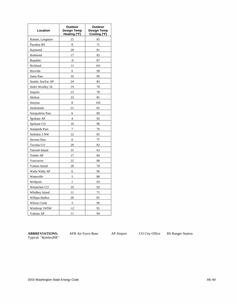
2015 Washington State Energy Code AE-49
Location Outdoor
Design Temp Heating (°F)
Outdoor Design Temp Cooling (°F)
Rainier, Longmire 15 85
Paradise RS 8 71
Raymond 28 81
Redmond 17 83
Republic -9 87
Richland 11 101
Ritzville 6 99
Satus Pass 10 90
Seattle: SeaTac AP 24 83
Sedro Woolley 1E 19 78
Sequim 23 78
Shelton 23 85
Smyrna 8 102
Snohomish 21 81
Snoqualmie Pass 6 80
Spokane AP 4 92
Spokane CO 10 96
Stampede Pass 7 76
Stehekin 3 NW 12 85
Stevens Pass 6 77
Tacoma CO 29 82
Tatoosh Island 31 63
Toledo AP 17 84
Vancouver 22 88
Vashon Island 28 78
Walla Walla AP 6 96
Waterville 1 88
Wellpinit 1 93
Wenatchee CO 10 92
Whidbey Island 11 71
Willapa Harbor 26 81
Wilson Creek 3 96
Winthrop 1WSW -12 91
Yakima AP 11 94
ABBREVIATIONS: AFB Air Force Base AP Airport CO City Office RS Ranger Station
Typical: "4(miles)NE"

AE-50 2015 Washington State Energy Code
APPENDIX D
RENEWABLE ENERGY
D101.1 On-site renewable energy systems. Each new commercial building or addition larger than 5,000 square
feet of gross conditioned floor area shall include a renewable energy generation system consisting of at least 70
watts rated peak photovoltaic energy production, or 240 kBtu of annual solar water heating energy production, per
1,000 square feet of conditioned floor area or fraction thereof. For buildings over 5 stories in height, the conditioned
area for this calculation shall be based on the conditioned area of the largest 5 above-grade stories in the building. If
the on-site renewable energy option in C406 is selected, this energy shall be in addition to that required by C406.
Exception: Alternate means of achieving equivalent energy savings are permissible where approved by the code
official, if the calculated net annual energy savings equals or exceeds the calculated annual energy production of
the required on-site renewable energy system.