wastemanagement ii. - waste management ii... · institute of environmental engineering volume 19....
TRANSCRIPT

University of Pannonia Environmental engineer Knowledgebase Series editor: Institute of environmental engineering Volume 19. Endre Domokos Dr.
This material was made by the TAMOP-4.1.2-08/1/A-2009-
0021 topic in the frame of University of Pannonia
Environmental engineering knowladgebase Series editor: Dr. Endre Domokos
19. volume
Wastemanagement II. Editor: Dr. Róbert Kurdi
Univrsity of Pannonia – Institute of environmental engineering
Dr. Róbert Kurdi (editor) Wastemanagement II. 1

University of Pannonia Environmental engineer Knowledgebase Series editor: Institute of environmental engineering Volume 19. Endre Domokos Dr.
This material was made by the TAMOP-4.1.2-08/1/A-2009-
0021 topic in the frame of University of Pannonia.
Environmental engineering knowladgebase Series editor: Dr. Endre Domokos
19. volume Wastemanagement II.
Editor: Dr. Róbert Kurdi
Szerzők: Buruzs Adrienn Csőke Barnabás
Czupy Imre Domokos Endre Fazekas Bence Horváth László Kárpáti Árpád
Kovács Barnabás Kurdi Róbert Nagy Géza
Pitás Viktória Szűcs István Szabó Imre Thury Péter
Torma András Vagdalt László
Vágvölgyi Andrea Várhegyi András
2012 Veszprém
University of Pannonia – Institute of environmental engineering
Dr. Róbert Kurdi (editor) Wastemanagement II. 2
University of Pannonia Environmental engineer Knowledgebase Series editor: Institute of environmental engineering Volume 19. Endre Domokos Dr.
Environmental engineering knowladgebase published volumes
01. Környezetföldtan 02. Környezetgazdálkodás 03. Talajvédelem, talajtan 04. Egészségvédelem 05. Környezeti analitika 06. Környezetvédelmi műszaki technológiák, technológiai rendszerek modellezése, ipari technológiák és szennyezéseik 07. Környezettan 08. Földünk állapota 09. Környezeti kémia 10. Vízgazdálkodás-Szennyvíztisztítás 11. Levegőtisztaság-védelem 12. Hulladékgazdálkodás 13. Zaj- és rezgésvédelem 14. Sugárvédelem 15. Természet- és tájvédelem 16. Környezetinformatika 17. Környezetállapot-értékelés, Magyarország környezeti állapota, monitorozás 18. Környezetmenedzsment rendszerek 19. Hulladékgazdálkodás II. 20. Környezetmenedzsment és a környezetjog 21. Környezetvédelmi energetika 22. Transzportfolyamatok a környezetvédelemben 23. Környezetinformatika II. 24. Talajtan és talajökológia 25. Rezgési spektroszkópia
Dr. Róbert Kurdi (editor) Wastemanagement II. 3

University of Pannonia Environmental engineer Knowledgebase Series editor: Institute of environmental engineering Volume 19. Endre Domokos Dr.
Terms of use: These materials are made in the Creative Commons project: „Nevezd meg!-Ne add el!-Így add tovább!” It can be freely use by the 2.5 Magyarország Licenc conditions.
In case of further use you must refer:
"Az anyag a TAMOP-4.1.2-08/1/A-2009-0021 téma keretében készült a Pannon Egyetemen."
For detailed informations visit the next link: http://creativecommons.org/licenses/by-nc-sa/2.5/hu/
Dr. Róbert Kurdi (editor) Wastemanagement II. 4

University of Pannonia Environmental engineer Knowledgebase Series editor: Institute of environmental engineering Volume 19. Endre Domokos Dr.
1. Table of contents
1. Table of contents ......................................................................................................... 5
2. List of figure ................................................................................................................ 9
3. List of Table ............................................................................................................... 12
4. Thesaurus .................................................................................................................. 13
5. Environmental protection and waste management (Csőke. B., translated by Mucsi G.) 18
5.1. Environmental impacts of waste ................................................................................... 19 5.1.1. Pollution of soil, ground water and surface water ........................................................................ 19 5.1.2. Air Contaminants ........................................................................................................................... 21 5.1.3. Danger of infection ........................................................................................................................ 23 5.1.4. Proliferation of insects and rodents .............................................................................................. 23 5.1.5. Esthetical importance of environmental contamination .............................................................. 23
5.2. Types of waste: waste from production and consumption ............................................ 24 5.2.1. Waste from production and consumption of human life ............................................................. 24 5.2.2. Classification of wastes ................................................................................................................. 25
5.3. Production- and product-integrated environmental protection ..................................... 27 5.3.1. Production-integrated environmental protection ........................................................................ 27 5.3.2. Product-integrated environmental protection ............................................................................. 27 5.3.3. Integrated hierarchic waste management conception and the production- and product-integrated environmental protection .......................................................................................................... 29
5.3.3.1. Tasks of waste generation prevention, avoiding and reducing the danger of wastes ........ 30 5.3.3.2. Reduction of waste quantity: recycling and utilization ....................................................... 32
5.4. Types of landfills ........................................................................................................... 33
5.5. Requirements of landfill emplacement ......................................................................... 35 5.5.1. General questions of location selection ........................................................................................ 35 5.5.2. The environmental geological requirements of landfill emplacement procedures, suitability criteria 37
5.6. Technical requirements of landfill design ...................................................................... 38 5.6.1. Subsoil requirements .................................................................................................................... 38 5.6.2. Structure of the bottom and cover liner system ........................................................................... 39
5.7. Aspects of the bottom liner system design .................................................................... 41 5.7.1. Geotechnical investigations .......................................................................................................... 41
5.7.1.1. Determination of the hydraulic conductivity ....................................................................... 43 5.7.1.2. The building of liner layer, construction standards ............................................................. 44
5.7.2. Materials of the bottom liner layers ............................................................................................. 46 5.7.2.1. Mineral bottom liners .......................................................................................................... 46 5.7.2.2. Geosynthetic liner layers (geomembranes) ......................................................................... 48
5.7.3. Structure and sizing of the leachate collection system ................................................................. 49 5.7.3.1. Design of the filtering- protective layer ............................................................................... 50 5.7.3.2. The selection of geotextiles ................................................................................................. 51 5.7.3.3. Material of the drainage layer ............................................................................................. 52 5.7.3.4. The design of the drainage layer ......................................................................................... 52 5.7.3.5. Determination of the expected volume of the leachate water ........................................... 53
5.8. Recultivation of landfills ............................................................................................... 57 5.8.1. General issues of the recultivation of landfills .............................................................................. 57 5.8.2. The temporal cover liner system of landfills ................................................................................. 60
Dr. Róbert Kurdi (editor) Wastemanagement II. 5

University of Pannonia Environmental engineer Knowledgebase Series editor: Institute of environmental engineering Volume 19. Endre Domokos Dr.
5.8.3. Legislation of the final cover system of landfills ........................................................................... 61 5.8.4. Alternative solutions by the elements of the cover liner system.................................................. 65
5.9. The monitoring system ................................................................................................. 66
6. Designing, development and sustainable maintainance of regional waste management systems (Buruzs Adrienn) ............................................................................ 68
6.1. Regulations and requirements ...................................................................................... 68
6.2. Concrete actions taken and specific progress made in implementation ......................... 69
6.3. Recent trends and emerging issues ............................................................................... 72 6.3.1. Waste management in hungary .................................................................................................... 72 6.3.2. Municipal solid waste generation ................................................................................................. 75
6.4. Practical implementation of waste management .......................................................... 76
6.5. Waste sources and composition .................................................................................... 77
6.6. Municipal solid waste ................................................................................................... 77
6.7. regional waste management systems ........................................................................... 77
7. The keys to a successful regional waste management system ................................... 79
7.1. Integrated approach for sustainable solid waste management ...................................... 79
7.2. An Urban Waste Management Continuum .................................................................... 81
7.3. Residual waste disposal, recycling and recovery ............................................................ 81
7.4. waste treatment technologies ...................................................................................... 82 7.4.1. A mechanical biological treatment system ................................................................................... 82 7.4.2. Composting ................................................................................................................................... 84 7.4.3. Materials recycling facilities (MRF) ............................................................................................... 85 7.4.4. Incineration ................................................................................................................................... 86 7.4.5. Refuse derived fuel (RDF) .............................................................................................................. 86 7.4.6. Other energy from waste processes ............................................................................................. 87 7.4.7. Gasification .................................................................................................................................... 87 7.4.8. Pyrolysis ......................................................................................................................................... 87 7.4.9. Landfill ........................................................................................................................................... 87
7.5. Solid Waste Management: A Policy and Programme Matrix .......................................... 88
7.6. Waste prevention and reduction ................................................................................... 89
7.7. Conclusion .................................................................................................................... 90
8. Methods of Municipal solid waste collection And transportation in regional waste management systems (Buruzs, Adrienn) ........................................................................... 91
8.1. introduction .................................................................................................................. 91
8.2. The quantity, the composition and organized collection of generated municipal solid waste 91
8.3. Municipal solid waste collection ................................................................................... 94
8.4. household waste recycling ............................................................................................ 94
8.5. Recycling collections ..................................................................................................... 95
8.6. charging for waste collection by the polluter-pays-principle .......................................... 97
8.7. KEY POINTS CONCERNING MAIN COLLECTION vehicles ................................................. 97
Dr. Róbert Kurdi (editor) Wastemanagement II. 6

University of Pannonia Environmental engineer Knowledgebase Series editor: Institute of environmental engineering Volume 19. Endre Domokos Dr.
9. COMPOSTING (Bence Fazekas, Viktória Pitás, Peter Thury, Árpád Kárpáti) .............. 102
9.1. Introduction ................................................................................................................ 102
9.2. Composting and its feedstock ..................................................................................... 103 9.2.1. Compostable materials ............................................................................................................... 103
9.2.1.1. Municipal sewage sludge ................................................................................................... 104 9.2.1.2. Industrial sewage sludge ................................................................................................... 104 9.2.1.3. Manure .............................................................................................................................. 104 9.2.1.4. Green (biogenic) waste ...................................................................................................... 104 9.2.1.5. Food and agricultural waste .............................................................................................. 105 9.2.1.6. Municipal solid waste ........................................................................................................ 105 9.2.1.7. Special waste ..................................................................................................................... 105
9.2.2. Energy recovery from waste ....................................................................................................... 105 9.2.2.1. Problems with wet feedstock ............................................................................................ 106 9.2.2.2. Problems with dry feedstock ............................................................................................. 106 9.2.2.3. Product quality requirements ............................................................................................ 107 9.2.2.4. Theory and practice ........................................................................................................... 107
9.3. Amendments of sewage sludge composting ................................................................ 107 9.3.1. Conditioning the feedstock ......................................................................................................... 107 9.3.2. Function of amendments and bulking agents during sewage sludge composting ..................... 108
9.3.2.1. Physical conditioning ......................................................................................................... 108 9.3.2.2. Chemical conditioning ....................................................................................................... 110 9.3.2.3. Energetic conditioning ....................................................................................................... 110 9.3.2.4. Oxygen demand of the oxidation of organic matter ......................................................... 111
9.4. Main steps of sewage sludge composting .................................................................... 112 9.4.1. Pre- and post-treatment ............................................................................................................. 112
9.4.1.1. Sewage sludge ................................................................................................................... 112 9.4.1.2. Operational variables ......................................................................................................... 113
9.4.1.2.1. Aeration ........................................................................................................................ 113 9.4.1.2.2. C/N ratio ....................................................................................................................... 113 9.4.1.2.3. Moisture content .......................................................................................................... 113 9.4.1.2.4. pH range and temperature ........................................................................................... 113
9.4.2. Composting technologies ............................................................................................................ 114 9.4.2.1. Open windrow ................................................................................................................... 114 9.4.2.2. Open static pile .................................................................................................................. 114 9.4.2.3. Enclosed reactor systems .................................................................................................. 115 9.4.2.4. In-vessel reactor systems ................................................................................................... 115
9.4.3. Aerated static piles in practice .................................................................................................... 116
10. Approaches to waste classification and treatment in nuclear industry (István Szűcs) 121
10.1. Challenges of radioactive waste classification ............................................................. 121
10.2. International classification of nuclear wastes .............................................................. 121
10.3. Radioactive waste classification in Hungary ................................................................ 125
10.4. The stored radwaste and spent fuel quantities in Hungary .......................................... 126 10.4.1. Inventory and rate of generation of HLW from NPP operation ............................................. 127 10.4.2. Inventory and rate of generation of L/ILW from NPP operation ............................................ 127 10.4.3. Rate of generation of LLW/ILW from small sources ............................................................... 128
10.5. Waste management policiy in Hungary ....................................................................... 128
11. Management principles and technical fundamentals for geological disposal of radioactive wastes (István Szűcs) ..................................................................................... 129
Dr. Róbert Kurdi (editor) Wastemanagement II. 7

University of Pannonia Environmental engineer Knowledgebase Series editor: Institute of environmental engineering Volume 19. Endre Domokos Dr.
11.1. International principles of radioactive waste management ......................................... 129
11.2. General approaches to radioactive waste management .............................................. 131
11.3. Technical fundamentals for geological disposal ........................................................... 134 11.3.1. The concept and definition of geologial disposal ................................................................... 134
12. Case history files of Hungarian radwaste management and research (István Szűcs) 137
12.1. Financial and managerial background ......................................................................... 137
12.2. Milestones of the low and intermediate level radwaste management ........................ 137
12.3. Milestones and background of spent fuel management .............................................. 138
12.4. Milestones and background of HLW management and research ................................. 141
12.5. Investigation of BCF as a potential host formation for HLW and spent fuel ................. 142 12.5.1. Short Term Programme (STP) of BCF ...................................................................................... 144 12.5.2. The main results of STP .......................................................................................................... 146
12.5.2.1. Main lithological and geometrical and features ................................................................ 146 12.5.2.2. Confinement performance considerations ........................................................................ 148
12.5.3. Safety concept of BCF according to the results of STP ........................................................... 149 12.5.4. Mid-term Programme (MTP) of BCF ....................................................................................... 153
13. Questions ............................................................................................................. 155
13.1. Environmental protection and waste management (Prof. Dr. Barnabás Csőke) ........... 155
14. References ............................................................................................................ 164
14.1. References with environmental and waste management chapter ............................... 164
Dr. Róbert Kurdi (editor) Wastemanagement II. 8

University of Pannonia Environmental engineer Knowledgebase Series editor: Institute of environmental engineering Volume 19. Endre Domokos Dr.
2. List of figure Figure 1.2.1. Material circuit generating waste ........................................................................ 24 Fig. 1.2. Open-cycle production-consumption process ............................................................ 28 Fig. 1.3. Closed-cycle production-consumption process ......................................................... 29 Fig. 1.4. Hierarchic waste management conception ................................................................. 30 Figure 1.5. The tasks of persons of society in the protection of waste generation .................. 31 Figure 1.6. Technological processes of recycling of electronic wastes ................................... 32 Figure 2.1.1. ............................................................................................................................. 34 Waste dumps built by landfilling ............................................................................................. 34 (Brandl, 1989.) ......................................................................................................................... 34 Figure 2.1.2. The cross-section of dump pit of “Aszód landfill for hazardous wastes” (Saubermacher Kft.) with the roof ........................................................................................... 35 Figure 2.2.1. ............................................................................................................................. 36 The landfill emplacement procedure ........................................................................................ 36 Figure 2.3.1. Legislation of the structure of the bottom liner system (20/2006.(IV.5.) KvVM Decree, Annex 1.) ..................................................................................................................... 39 Figure 2.3.2. Hungarian legislation of the structure of the top (cover) liner system of landfills for inert wastes (20/2006.(IV.5.) KvVM Decree) .................................................................... 40 Figure 2.3.3. Hungarian legislation of the structure of the top (cover) liner system of landfills for non-hazardous (category B1b) wastes (20/2006.(IV.5.) KvVM Decree) ........................... 40 Figure 2.3.4. Hungarian legislation of the structure of the top (cover) liner system of landfills for non-hazardous (category B3) wastes (20/2006.(IV.5.) KvVM Decree) ............................. 40 Figure 2.3.5. Hungarian legislation of the structure of the top (cover) liner system of landfills for non-hazardous (category C) wastes (20/2006.(IV.5.) KvVM Decree) ............................... 41 Figure 2.4.1. ............................................................................................................................. 43 Determination of the hydraulic conductivity of clays in triaxial cell ....................................... 43 Figure 2.4.2. The field determination of the hydraulic conductivity of the bottom liner system of landfills by pipe-type infiltrometer (BRANDL, 1989.) ....................................................... 44 Figure 2.4.3. Determination of hydraulic conductivity, shear strength, and construction parameters suitable also in aspects of shrinkage (DANIEL, 1993.) ........................................ 45 Figure 2.4.4. ............................................................................................................................. 46 Recommended construction water content (wconst) during the building of liner layers ......... 46 Figure 2.4.5. ............................................................................................................................. 47 Summary of results of the hydraulic conductivity tests of GCLs ............................................ 47 (ESTORNELL-DANIEL, 1992.; University of Miskolc, 2002.; GEOSZABO, 2005.) .......... 47 Figure 2.4.7. ............................................................................................................................. 53 The model of the design of the leachate collection (drainage) layer I. .................................... 53 (McBean et al., 1981.) .............................................................................................................. 53 Figure 2.4.8. ............................................................................................................................. 54 Water balance of landfills ........................................................................................................ 54 Figure 2.4.9. ............................................................................................................................. 56 Construction of the drainage system ........................................................................................ 56 (RAMKE, 1991.) ...................................................................................................................... 56 Figure 2.4.10. ........................................................................................................................... 57 Construction method of drain pipes ......................................................................................... 57 (DIN 19667, 1990.) .................................................................................................................. 57 Figure 2.5.1. Selection of the recultivation method ................................................................. 60 Figure 2.5.2. ............................................................................................................................. 62
Dr. Róbert Kurdi (editor) Wastemanagement II. 9

University of Pannonia Environmental engineer Knowledgebase Series editor: Institute of environmental engineering Volume 19. Endre Domokos Dr.
Determination of the required water content of the mineral barrier at the construction of the cover liner system ..................................................................................................................... 62 Figure 2.6.1. ............................................................................................................................. 67 The elements of the monitoring system of the landfill ............................................................. 67 Figure 1. Proportion of incineration recycling and landfilling of MSW .................................. 73 Figure 2. The operating landfills between 2005 and 2009 and after 2009 ............................... 74 Figure 3. The elements of a basic waste management system ................................................. 80 Figure 4. Integrated sustainable solid waste management system ........................................... 81 Figure 5. The options for dealing with municipal solid waste – "waste hierarchy" ................. 81 Figure 6. Process flow chart of MBT ....................................................................................... 83 Figure 7. Covered MSW with semipermeable film ................................................................. 83 Figure 8: Waste after MBT treatment ...................................................................................... 83 Figure 9. Classification of treated waste .................................................................................. 84 Figure 10. Baling machine ....................................................................................................... 84 Figure 11. Open-system composting plant ............................................................................... 85 Figure 12. Domestic waste sorting machine ............................................................................ 86 Figure 1. The specific quantity of generated municipal solid waste in regions in 2004 .......... 92 Figure 2. The composition of produced municipal solid waste (Source: The developing strategy of municipal solid waste management 2007–2016) ................................................... 92 Figure 3: Analysis of the content of the typical household waste in the EU ........................... 93 Figure 4: Different types of municipal waste containers ......................................................... 95 Figure 5: Waste collection points for different types of recycling waste ................................. 96 Figure 6: Waste collection yard ............................................................................................... 96 Figure 6: Additional container for biodegradable waste collection in Győr region ................. 97 Figure 8: Overview of transfer station ..................................................................................... 99 Figure 8: Truck for container transportation .......................................................................... 100 Figure 9: Truck for container transportation .......................................................................... 101 Fig 2.2.1.1. The function of bulking materials. ...................................................................... 109 Fig. 2.2.1.2. The conditioning of the feedstock, example (mass ratio). ................................. 109 Fig. 2.2.1.3. The amount of wood chips needed to increase the dry solid content of sewage sludge (two different data series). .......................................................................................... 110 Fig. 2.2.4. The effect of the moisture content of digested sewage sludge on the amount of water that must be evaporated during composting. ................................................................ 112 Fig. 3.3.1. Static composting of sewage sludge and wood chips. .......................................... 116 Fig 3.3.2 Construction of a static pile for the composting of 40 m3 dewatered sewage sludge. ................................................................................................................................................ 117 Fig. 3.3.3. Temperature distribution during the composting of sewage sludge and wood chips in an aerated static pile. .......................................................................................................... 117 Figure 3.3.4. shows the temperature profiles of composting different sewage sludge with different amendments. ............................................................................................................ 118 Fig. 3.3.4. Scheme of an aerated static pile composting ........................................................ 118 Table 3.3.1. Mass balance of an aerated static pile. ............................................................... 119 Fig. 3.3.5. Performance of air blowers by the static pile composting of raw sewage sludge with 25% dry solid content and bulking materials. ................................................................ 119 Fig. 1.2. Example of the application of the waste classification scheme. (According to IAEA Safety Standards No. GSG-1, 2009) The numbers refer to examples of disused sealed sources set out in the upper table. The Naturally Occuring Radioactive Materials in the earth’s crust called as NORM. (Just for comparison: the approximate order of range of radioactivity content of the world seas is: 1022 Bq; Hiroshima bomb emission to the air: 1016 Bq;
Dr. Róbert Kurdi (editor) Wastemanagement II. 10

University of Pannonia Environmental engineer Knowledgebase Series editor: Institute of environmental engineering Volume 19. Endre Domokos Dr.
Chernobil disaster’s emmission to the air: 4x10¹⁸ Bq; All radwastes of the world’s NPPs of the last half century: 1021 Bq) ............................................................................................... 124 Fig 1.3. Location of Paks NPP and existing/planned radwaste disposal facilities ................ 126 Fig. 2.1. Advised repository options for final disposal of different radioactive wastes ........ 132 Fig. 2.2. Places and depths of URLs for investigations of different potential host rock formations all over the world (WIPP, USA is the only HLW repository ― for the radwastes with neglecting heat emission ― in the world) ...................................................................... 132 Fig. 3.1. Comparison of open (up) and closed (down) nuclear fuel cycle. (MOX: is nuclear fuel that contains more than one oxide of fissile material. More than 95% of the spent fuel consists of: UO2.) ................................................................................................................... 139 Fig. 3.2. Left: Distribution of uranium research boreholes surrounding of BCF; Right: West-East (see line 2 on next figure) geological section of BCF (brown) and location of alpha-project’s excavation tunnel transformed to an URL .............................................................. 143 Fig. 3.3. Geological map of the Western-Mecsek Anticline with the location of URL (circled with green) and surface outcrop area of BCF (dark brown) .................................................. 143 Fig. 3.4. Geological cross-section in the vertical plane of the Alpha-1 exploratory tunnel (1000 m under the surface) ..................................................................................................... 145 Fig. 3.5. North-South (see line 1 on Fig.3.3.) geological section of the anticline structure BCF (brown) and neighboring layers ............................................................................................. 147 Fig. 3.6. Lithological column of the BCF with upper (topset beds)- and lower (substrate) surrounding layers .................................................................................................................. 148 Fig. 3.7. The concept of a disposal with multibarrier system ................................................ 149
Dr. Róbert Kurdi (editor) Wastemanagement II. 11

University of Pannonia Environmental engineer Knowledgebase Series editor: Institute of environmental engineering Volume 19. Endre Domokos Dr.
3. List of Table Table 2.4.1. Selection of the material of the liner layer is based on the tests .......................... 42 Table 2.4.3. The requirements of the construction of leachate collection system ................... 50 Table 2.4.4. Intensity of the leachate water as a function of the annual sum of precipitation . 55 Table 2.4.5. Leachate intensities .............................................................................................. 55 Table 2.5.1. The most favourable soils for recultivation layer ................................................ 64 Table 1. Annual waste production and the GDP in Hungary ................................................... 70 Table 2. Generation of municipal solid waste (MSW) and the GDP ....................................... 70 Table 3. Waste treatment in Hungary (without waste water sludge) ....................................... 71 Table 4. Treatment of municipal solid waste (1000 tons) ........................................................ 71 Table 5. Strengths and Weaknesses of MBT ........................................................................... 82 Table 6. Dimensions of decision-making ................................................................................. 89 Table 3.3.2. Energy content of some feedstock. .................................................................... 120 Table 1.1. Activity concentration intervals of radioactive wastes ........................................ 125 Table 1.2. Exemption activity concentrations (EAC) of some radionuclides ........................ 125 Table 1.3. Activity concentration intervals of radwastes containing several types of radioactive isotopes ................................................................................................................ 126 Table 1.4. L/ILW, HLW and SF storage capacities and quantities in Hungary (2010) ......... 127 Table 2.1. Principles of radwaste management (According to IAEA Safety Requirements No. WS-R-4 Annex II. 2006) ........................................................................................................ 130 Table 2.2. Nuclear waste management strategies and latest developments of different countries for spent fuel and HLW from NPPs; Source: http://www.world-nuclear.org/info/inf04.html .................................................................................................... 133 Table. 3.1. The main geotechnical (up) and mineralogical (down) parameters of BCF, according to [17] .................................................................................................................... 151
Dr. Róbert Kurdi (editor) Wastemanagement II. 12

University of Pannonia Environmental engineer Knowledgebase Series editor: Institute of environmental engineering Volume 19. Endre Domokos Dr.
4. Thesaurus Acetogenesis The formation process of organic acids during biogas fermentation.
Aerobic Requiring the presence of air’s oxygen. Anaerobic Not necessitating the presence of air’s oxygen. Chip The specific surface of one m3 of logs of wood is about 100-300 m2/m3, for the same volume of wood chips it is 20000-30000 m2/m3 (more favourable as regards to firing). Batch Charging, feeding. Bio briquette Primarily the compaction of lignocellulosics, with a moisture content fo 8-14% and a cross-section of 20-100 cm2. Biodiesel There are two types of vegetable oils which are suitable as a substitute for diesel fuels: pure vegetable oils and their esterified derivatives. Bioethanol Fuel consisting mainly of ethyl-alcohol. Biofilter Medium for filtering out air pollutants. Biogas Biogas is a product formed during the anaerobic breakdown of organic matter by micro-organisms. Biomass Biomass is mainly composed of organic matter built-up by carbon, hydrogen and oxygen. It is highly suitable for substituting fossil energy resources as it contains low amounts of minerals and other matter detrimental in terms of energetic utilization. Bio manure By-product of the fermentation process, suitable for recovering the producing power of the soil. Decanter Enables the continuous and controlled separation of solids from liquids. Dendromass
Dr. Róbert Kurdi (editor) Wastemanagement II. 13

University of Pannonia Environmental engineer Knowledgebase Series editor: Institute of environmental engineering Volume 19. Endre Domokos Dr.
Firewood, wood produced for power generation, felling site harvesting losses (energy wood). Torching Firing of biogas using a torch. Usually applied if the produced biogas can not be utilized in any other technology or too much biogas is produced. Gasification The direct conversion of biomass into gas using oxygen or steam. Energy forest plantation Plantation, classified into the plantation agriculture land-use class, suitable for the production of dendromass (energy wood). Energy forest Forest, classified into the sylvicultural land-use class, but set-up and operated with special purposes. Energy forests can be established by requalifying traditional forests or by planting special energy tree species. Extractives Accessory materials, secondary metabolites. Semi-dry technology Technology applying reactors with charges of 15-24% dry mass proportion. Fermenter Digester tank, also used for producing biogas. Fermentation Chemical process in which organic matter is enzymatically decomposed (fermented). Calorific value, heat of combustion The heat of combustion is the energy released as heat when the fuel of unit mass and volume undergoes complete combustion with oxygen. In practice, the concept of calorific value is more commonly used than that of the heat of combustion. When calculating calorific value, it is accounted that the moisture content of the combustion products are to be found in the gas (vapour) and not in the liquid phase, that is to say, the combustion products do not release their heat of evaporation while cooling down. Calorific value is thus lower than, or equal to the heat of combustion. Gas engine Internal combustion engine running on a gaseous fuel. The engine produces heat while its main shaft drives a generator. Ash content Ash content represents the aggregate of minerals left behind after burning biomass. Hemicellulose Carbohydrate fraction that can be found in the cell wall of plants. Sanitization
Dr. Róbert Kurdi (editor) Wastemanagement II. 14

University of Pannonia Environmental engineer Knowledgebase Series editor: Institute of environmental engineering Volume 19. Endre Domokos Dr.
Disinfection process. Waste Matter or energy of anthropogenic source which can not be, or is not intended to be utilized or marketed. Waste management The system of activities associated with waste, including the prevention of waste generation, reduction of the amount and harm of waste, waste treatment and handling, planning and controlling of the aforementioned activities, operation, closing down and after-care of the waste-handling installations and facilities, running investigations and education (technical advice) following the closing-down. Humification Formation of humus (humic substances); the transformation of deceased animal and plant residues into soil. Compost Compost is stabilized organic matter consisting of minerals and products formed by microbes. It is soil-like, containing humic substances and vegetable nutritives with a moisture content of approximately 40-50%. Conditioning Step of the biodiesel production process, aiming at the increasing the specific weight, the oil content and the softness of the basic material in order to get a better oil-yield and to enhance the performance and the service life of the pressing machine. Confectioning Finishing the product. Lignocellulosics Mixture of organic polymers (cellulose, hemicellulose and lignin). Random sampling by hand Some amount of the compost is taken in the hand, crushed and its behaviour is observed. If the moisture content is optimal water does not flow out between the fingers and the compost sticks together. If it is too dry, it will crumble in our hands. If it is too wet, the excess water will flow out between the fingers. Membrane Thin, resilient sheet of film. Methanogenesis The methane formation process during biogas fermentation. Mesophilic Preferring medium warm temperatures. Mineralisation
Dr. Róbert Kurdi (editor) Wastemanagement II. 15
University of Pannonia Environmental engineer Knowledgebase Series editor: Institute of environmental engineering Volume 19. Endre Domokos Dr.
The process through which an organic substance becomes impregnated by inorganic substances in the soil, thus becoming available as a nutrient. Engine propellant Engine propellants are liquid or gaseous hydrocarbons. Traditional propellants (petrol, diesel) are primarily produced by the distillation of petroleum. Wet technology Technology applying reactors with charges of 0.5-1% dry mass proportion. Octane number The measure of the antiknock quality and the self-ignition properties of petrol as compared to the respective qualities of iso-octane. Optimal Best, most suitable. Self-heating test Test to determine the degree of compost curing. Pathogen Parasite, pathogen Pellet Pellet is a special version of the bio briquette, with an average diameter of 5-10 mm, and a length of 10-25 mm. It can be fed easier into the firing area and has a better burning efficiency than the briquette. Percolation process Continuous extraction. Pyrolysis Thermal decomposition of organic wastes in a suitable reactor in an oxygen-poor or completely oxygen-free atmosphere under controlled conditions. Psychrophilic Preferring cold temperatures. Coppice forestry/system The plantation is introduced with a large number of stems (8000-15000 pieces/hectare) with species which produce coppices fast; the time of the first clear-felling is between 3-5 years depending on the cutting and harvesting techniques. With the same cycles the coppice plantation can be harvested again; altogether 4-5 felling cycles can be considered. It is usually rentable, its only drawback is that the number of stems during coppicing can hardly be controlled (Rédei et. al., 2009). Dry technology Technology applying reactors with charges above 25% of dry mass proportion. Semipermeable
Dr. Róbert Kurdi (editor) Wastemanagement II. 16
University of Pannonia Environmental engineer Knowledgebase Series editor: Institute of environmental engineering Volume 19. Endre Domokos Dr.
Allowing only certain molecules and ions to pass through (e.g. through a membrane). Distiller’s wash The by-product of bioethanol production. Suspension technology Technology applying reactors with charges of 5-15% dry mass proportion. Thermophilic Preferring warm temperatures. Toxic Poisonous, virulent. Reafforestation system/forestry After complete soil preparation, planting of high dendromass-yielding tree species. The plantation is introduced with 5000-8000 stems/hectare; applying 8-15 years of rotation period an average green mass yield of 8-15 tonnes/hectare/year can be achieved depending on the properties of the site, species and cultivation technology. It is a less profitable system because of the longer rotation periods. Fuel Fuels are propellants, lubricants and coolants which are required for running internal combustion engines. Felling site harvesting losses Residual parts of the tree left back at the felling site: bark, small branches, twigs.
Dr. Róbert Kurdi (editor) Wastemanagement II. 17

University of Pannonia Environmental engineer Knowledgebase Series editor: Institute of environmental engineering Volume 19. Endre Domokos Dr.
5. Environmental protection and waste management (Csőke. B., translated by Mucsi G.)
The process of satisfying human needs results large amounts of waste: namely the
production and consumption always generate such residue, product, used device or packaging which their owner is not able or does not wish to use at the place of origin - because of economical and technical reasons - not for the original purpose nor other purpose, from which therefore must get rid of – this is the waste.
The process begins with the intensive exploitation of mineral raw materials and primary
materials of food which result significant intervention in the environment. The landfill of waste from the industry, agriculture, trade and services, residential and institutional consumption can cause remarkable nuisance and it reduces valuable fields from nature and agriculture. For the society there is no other possibility to that the production and the consumption should be performed in an environmental- and natural resource-friendly way essentially by using technologies preventing waste generation and producing environment friendly products, secondly by recycling as much waste material as possible in the production-consumption process and by treating, disposing wastes. This activity is called waste management.
For a human being the protection of environment is - beside the above mentioned issues -
basically a moral responsibility for the Earth. Contrary to the previous centuries the men of the 21st century will need significant changes in their attitude, if they want to leave their living space – the Earth – suitable for life for future generations too. The man must abandon his conventional predominant ideology and behavior, according to this, sitting up on the throne of the World, he believes he can decide absolutely about the fate of the World dominated and formed by himself for his own needs. The anthropocentric World should be changed to an anthropophob World. (According to BRAUER H., 1995, [1] Band 1)
The man has the right and the obligation to satisfy the needs of their social existence. This
task is fulfilled in a creative manner by protecting the environment.
The man can intervene the World, however like not the Monarch of all life on Earth, but Partner of the World – due to his power and creativity (Homo Faber) he is responsible for all life. Only the Man is able to keep the equilibrium of Life in the dynamically changing World. This is the obligation of constructive Man (Homo Morales). (According to BRAUER H., 1995, [1] Band 1)
Meeting the growing needs is possible with the conscious development of production and consumption, but only the harmonic development can be sustainable for long-term. That development is harmonic in which the given social and economic activities conform to the sustainer-ability of environment.
Dr. Róbert Kurdi (editor) Wastemanagement II. 18

University of Pannonia Environmental engineer Knowledgebase Series editor: Institute of environmental engineering Volume 19. Endre Domokos Dr.
From this point of view the environmental protection is not prohibitory and impediment, but active supporter of the development. In this approach the object of the environmental protection is: While forming the dynamic World to reveal the technical opportunities by engineering and scientific way which are necessary to protect the environment and to correct the mistakes caused by Man, at the same time these possibilities do not limit the constructive Man (development). (According to BRAUER H., 1995, [1] Band 1)
5.1. Environmental impacts of waste The waste affects the environment because it is necessary to landfill, whereby the soil, the
water and the air can be contaminated (emission from landfills). The landfilled waste implies environmental risk due to its quantity, danger and aggression. Therefore the conscious protection of the environment based on the analysis of emissions and their effects; since we have to know what kind of problem we should defend against and what the risk of negligence of protection is. Knowing the degree of risk allows to determine the value of acceptable risk and to optimize the costs of protection in the production integrated environmental protection as well as in the direct environmental protection (cleaning of air, water and soil), or in the case of elimination of damage made by people. Today it is necessary that the producer should have the highest possible knowledge about the environmental risk of production and consumption; furthermore producer should accept responsibility for not only the production waste but the waste originated from the amortization and damage of the product as well as its environmental risk and protection costs of recycling, utilization and landfilling.
The effect of environmental damage of waste released to the environment and not treated correctly can appear diversely. 5.1.1. Pollution of soil, ground water and surface water Necessarily wastes are mostly landfilled in specially designed dumpsites on the ground surface. Hazardous components from the not suitably managed, not cultivated landfills and from the waste transportation devices are washed into the soil by rainwater(Bonnyai, Z., 2000, [6]: p.590). Contaminated liquid leaking into the soil can get at greater distance by approaching the ground water and hence the spreading pollutants can contaminate bigger areas. It is extremely critical that the pollution endangers water basis in grater distance by streaming ground water. In this environment damaging progress the generated so called acidic gases (nitrogen oxide, sulphur dioxide) have an important role, since with addition of water they produce acids which can get into and onto the soil, and react with soil components (Hopp, J., 2003, [3]: p.171): Alkaline soils neutralize them, in this case the effect is insignificant; however in case of soils with low buffering capacity (pH 5-4,2) acids solute the Al cations which damage the roots of plants. Additionally, the low pH value mobilizes the cations (Cu2+, Zn2+, Ni2+) of heavy metal compounds and leach nutrients into the ground water. Both processes damage the fertility of soil. Effect of heavy metals
Dr. Róbert Kurdi (editor) Wastemanagement II. 19

University of Pannonia Environmental engineer Knowledgebase Series editor: Institute of environmental engineering Volume 19. Endre Domokos Dr.
The effect of heavy metals getting into and onto the soil on the biota of soil (plants, animals and microorganism) depends on the behavior of heavy metal compounds in the soil talajban (Hopp, J., 2003, [3]: p.172): High concentration of heavy metals blocks the soil breathing, N-mineralization and activity of enzymes. These relations strongly depend on the chemical, physical and biological properties of soils (soil types). The copper, nickel, lead, zinc and cadmium can be adsorbed well in the clay minerals of soil, and react with organic fractions of the soil producing humic acid complex. Furthermore, plants take in the relatively easily soluble nickel, zinc and cadmium from ground water, in this way these ions can return to people. So, the lower the clay mineral and humus content of the soil, the higher the mobility of metals. Heavy metals have toxic effect on the microorganisms of soil in the following order (Wilke, B.M., 1996, [1]:Band 1, p.487): Zn, Pb, Ni< Cu, Cd, Co, Cr <Hg The effect of free metal ions is more toxic than that of hydroxide-complex compounds (for instance CdOH+, Cd(OH)2 ). The toxicity of heavy metals on the living organisms is mainly based on the inactivation of enzymes (Förstner, 1993, [5]: p.74): Metaelements (mercury, cadmium) easily react with proteins. Metals reduce the permeability of cell membranes, modify the DNA and have carcinogenic influence. The inorganic compounds damage mainly the kidney and liver, vapor of mercury affects the innervation. Additionally, mercury is accumulated in the nutrient chain, viz. bacteria transform mercury to lipophilic (soluble in fats), thus planktons (algae, crab) can take them and these are the nutrient substance of fishes and shells. The toxicity of heavy metals is increased by the kind of their electropositive behavior (Förstner, 1993, p.76): Cu<Ag<Au; Zn<Cd<Hg; Al<Ga<In<Tl . Effect of organic contaminants Accumulation of organic materials in soil depends on several factors. The most important environment relevant factors are [1]: vapour pressure, water-solubility, distribution coefficient octanol/water (=Po/w), ad- and desorption in soil, effect of material characteristics on the biological system of soil, degradation and accumulation in soil, influence on humans and animals. The behavior and effect of organic pollutants can be summarized as follows (Hopp, J., 2003, [3]: p.174 and Förstner, 1993, [5]: p.85):
• Lipophilic materials can be adsorbed by the humus fraction of soil [3]. • The richer the humus content of soil, the higher its adsorption capacity [3]. • The ionic organic materials can be adsorbed easily by the clay minerals, manganese-
and iron-oxides, -hydroxides [3]. The cationic or basic compounds adsorb on surface with negative charge almost irreversibly, the acidic compounds are rejected by the negative organic or inorganic particle surface [5].
• The apolar, easily volatile materials (for example toluol) are linked with weak “hydrophobic” bond, the hardly volatile materials (for example hexachloric-benzole) are linked with strong bond to organic particles [5].
• The adsorption of toxic organic materials is mostly reversible: by changing the pH, the oxidation-reduction potential and the concentration in soil solution they become free again [3].
Dr. Róbert Kurdi (editor) Wastemanagement II. 20
University of Pannonia Environmental engineer Knowledgebase Series editor: Institute of environmental engineering Volume 19. Endre Domokos Dr.
The degradation, transformation, mineralization of wastes and organic materials are carried
out by the soil and the microorganisms of soil. This process under natural circumstances leads to the auto-purification of soil.
On the surface of the soil photochemical reactions are taking place in the organic materials
(Hopp, J., 2003, [3]: p.174): Due to the effect of oxygen and the high energy radiation the carbon-chains are decomposed and oxidized in a multistage process CO2 and water are generated. In the deeper soil layers the activity of microorganisms (bacteria, fungus) plays important role: the solid organic materials are decomposed to liquid and gas components (CO2, CH4, NH3, H2S …). During this process (mineralization) the organic materials are mineralized to carbon-dioxide, water and ammonia, this latter one is transformed to nitrite and nitrate during the nitrification (Takács, S., 2002, [4]: p.132). The contaminations endanger the self-purification process. However it happens often that the degradation of organic contaminants due to the microorganisms leads to generate such materials which are not harmful, but it can result more hazardous materials metabolites (metabolic product) which are resistant to the microbiological and photochemical decomposition, therefore these are accumulated in soil (Hopp, J., 2003, [3]: p.174).
The organic contaminants can be leached, washed to the ground water. The stability of
chlorinated compounds (PCBs) depends on the modification (Förstner, 1993,[5]: p.89): the higher-rated chlorinated compounds have higher stability. The solubility of the macromolecular chlorinated compounds in water is lower than that of low-molecular: the affinity to suspended-matter increasing with reducing water solubility. From the point of view of water contamination the vapour pressure depending on the temperature is of great importance. The water pollution can be characterized by
16,04 .103 x vapour pressure x water solubility x T temperature (Celvin) Henry-coefficient (Förstner, 1993,[5]: p.89). Organic matters with higher than H103 coefficient reside short time in water.
Toxic effect of organic matter prevails directly or indirectly (storage, storage as metabolic product) [5]. Carcinogenic products can be generated from polycyclic aromatic materials, it can cause organ damage. The PCBs are accumulated in the adipose tissue and influence the generation of haemoglobin, it causes metabolism disorder and demolishes the resistance against diseases of the organism [4, 5]: Compounds with high stability have high intoxication potential. The strongest toxic organic compounds are: the chlorinated dibenzodioxin, the polychlorinated dibenzodioxins, polychlorinated dibenzofuran. These compounds are generated mainly during the production of organic chlorine compounds, the paper production (paper/cellulose whitening) and the thermal processes utilizing organic waste materials. 5.1.2. Air Contaminants
However, not only the soil, but the air is endangered by the not suitable waste treatment as well as by the landfill (Bonnyai, Z., 2000 [6]: p.590). During the degradation of biologically degradable organic matters environment polluting gases – ammonia, hydrogen sulphide, methane - are generated and get into the air and by means of methane and carbon-dioxide they contribute to the greenhouse effect. Carbon-monoxide, carbon black, dioxin, furan, sulphur-
Dr. Róbert Kurdi (editor) Wastemanagement II. 21

University of Pannonia Environmental engineer Knowledgebase Series editor: Institute of environmental engineering Volume 19. Endre Domokos Dr.
dioxide - generated by spontaneous combustion of landfilled waste - are especially hazardous for the wildlife and human. Concerning the effect of air pollutions on the human body it can be emphasized the following (Lahmann, E., 1995, [1]: Band 1, p.135-136): Respiratory tracts can be sickened by: sulphur-dioxide, nitrogen-dioxide, ozone, formaldehyde, toxic (Pb, Cd, Cr, Mn, Ni) bearing and acid (sulphuric acid, nitric acid) adsorbed dust, asbestos. Heart and vascular system can be damaged by: carbon-monoxide, halocarbons, metals (As, Cd, Pb, Sb, Ba, Co, Tl), silicosis-causing dusts (asbestos, quartz, organic dusts). Damaging to immune system: heavy metals (Cd, Pb, Hg, Ni, Co, Cr), halohydrocarbons (dioxin (TCDD), hexachloride benzene, PCB, pesticides). Blood-forming system can be damaged by: lead, carbon-monoxide, nitrogen -dioxide, benzene, arsenic and its organic complexes. Metabolism/secretory (liver, kidney) system damaging air contaminants: Liver: metals (As, Sb, Be, Cd, Pb, Cr, Co, Cu, Hg, Sn, Zn), chlorinated aliphatic and cyclic hydrocarbon (dioxin, furan), mercaptan, amines. Kidney: metals (As, Cd, Pb, Cr, Hg, Ni, Bi, V), chlorinated aliphatic and cyclic hydrocarbon (polychlorinated dibenzo dioxin, polychlorinated dibenzo furan, vinylidene chloride, ethynyl trichloride, butadiene hexachloride, ethynyl trichloride). The effect of air pollutants on wild-, domestic animals and livestock is similar to that of the humans; however the research on this field is poorish. The effects on the flora can be summarized as follows (Lahmann, E., 1995, [1]: Band 1, p.145): The above pollutants are accumulated in the plant-parts mainly in leaves, or they are transported in the metabolic processes and secreted. The damage appears in growth-, tolerance- and value reduction; finally it can lead to total damage. The harmful gas, which is penetrated into the plant through the rupture of the leaves, essentially damaging the assimilation system, can cause the necrosis of the plant. The influence of sulphuric-dioxide on the plant is well investigated. According to our knowledge sulphuric-dioxide in low concentration (<20 μg/m3) helps plant to grow, serve as nutritive. In high concentration SO2 causes serious damages in plants: decomposes the chlorophyll leading to the necrosis of the plant tissues. This effect, like the influence of acidic rain, is well known, which causes death of woodlands. The fine dust of the collected and landfilled waste dump can be carried by wind. The microorganisms (bacteria, viruses, fungus) in the air and in the waste, so called germs are generally settled on the dust particles and water drop of air. The multiplication of bacteria and viruses is almost totally blocked by dryness, UV radiation and cold. However, several fungus spores can live for long time under the above conditions (Schwister, K. 2003, [3]: p.180).
Dr. Róbert Kurdi (editor) Wastemanagement II. 22

University of Pannonia Environmental engineer Knowledgebase Series editor: Institute of environmental engineering Volume 19. Endre Domokos Dr.
5.1.3. Danger of infection Microorganisms of several infectious diseases from municipal waste, numerous untreated
production (agricultural, food- and pharmaceutical industry) wastes can get to the environment, soil and air. In these kinds of wastes many microorganisms – viruses, bacteria, spores, and worm eggs - can be found and they are carrying infectious diseases (Bonnyai, Z., 2000, [6]: p.590; Takács, S., 2002). Under appropriate circumstances the pathogens (especially spored, egged and cystic microbes) are viable for long period of time in the waste, from where they can get into the soil, water and they can cause infection through direct contact (Takács, S., 2002). The most significant danger for human implies spores and endoparasites originated from the faecal matter of domestic animals getting into the waste and soil (for example tetanus, endoparasite), which are viable for years or decades. The pathogens in the waste indicate the possibility of infection, therefore this kind of waste can be considered as infection-transmitter medium. 5.1.4. Proliferation of insects and rodents
Through the inappropriate treatment of municipal waste, inappropriate compacting, absence of top layer, delayed making of top layer insects (cockroach, fly) and rodents (rat, mouse) proliferate dramatically (Bonnyai, Z., 2000, [6]: p.591). Insects and rodents are infectious disease-carrying animals. Temporary storage or the inappropriately compacted waste or waste stored for too long time may cause problems as well. 5.1.5. Esthetical importance of environmental contamination Through the inappropriate waste transportation and the absence of covering of landfilled waste, the light fractions – mainly plastic and paper - of the waste are carried by wind and spread in big areas which damage the original aesthetic spectacle of the landscape (Bonnyai, Z., 2000, [6]: p.591). Nevertheless, not only the beauty of the landscape is damaged but it causes direct economic damages by reducing the economic value of the land. The aims of environmental protection based on ideas of sustainable development are: • to assure the healthy and worthy environment for human, • to protect the soil, air, water, flora and fauna against the injury caused by human activity, • to eliminate environmental damages caused by human intervention.
The harmful effects and pollutions on the environment connected to the economic and
social activity (production, distribution, consumption) of the man, therefore the prevention, reduction or elimination of damaging effects require to validate environmental aspects in all areas of economy (agriculture, industry, energetics, traffic,…), and in the innovation process too (research, planning, realization, operation).
In order to realize the above aims the activity of environmental protection is extended [1, 2]: • to reduce the environmental contaminants and damages, especially to reduce wastes
(production and product integrated environmental protection); • to analyze the emissions and effects of the environmental contaminants and damages; • and to moderate the influences by mainly technical devices and methods (additive
environmental protection); • to eliminate the environmental contaminants and damages occurred.
Dr. Róbert Kurdi (editor) Wastemanagement II. 23
University of Pannonia Environmental engineer Knowledgebase Series editor: Institute of environmental engineering Volume 19. Endre Domokos Dr.
5.2. Types of waste: waste from production and consumption 5.2.1. Waste from production and consumption of human life
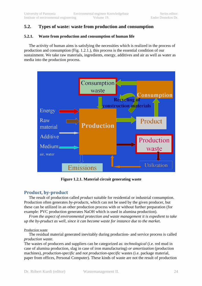
The activity of human aims is satisfying the necessities which is realized in the process of
production and consumption (Fig. 1.2.1.), this process is the essential condition of our sustainment. We take raw materials, ingredients, energy, additives and air as well as water as media into the production process.
Figure 1.2.1. Material circuit generating waste
Product, by-product The result of production called product suitable for residential or industrial consumption.
Production often generates by-products, which can not be used by the given producer, but these can be utilized in an other production process with or without further preparation (for example: PVC production generates NaOH which is used in alumina production).
From the aspect of environmental protection and waste management it is expedient to take up the by-pruduct as well, since it can become waste for instance due to the market.
Production waste
The residual material generated inevitably during production- and service process is called production waste. The wastes of producers and suppliers can be categorized as: technological (i.e. red mud in case of alumina production, slag in case of iron manufacturing) or amortization (production machines), production-specific and not production-specific wastes (i.e. package material, paper from offices, Personal Computer). These kinds of waste are not the result of production
Dr. Róbert Kurdi (editor) Wastemanagement II. 24

University of Pannonia Environmental engineer Knowledgebase Series editor: Institute of environmental engineering Volume 19. Endre Domokos Dr.
and service activity (that is the product) but usually its unavoidable consequences, residual materials.
A part of the technological production waste is usually not hazardous for environment or it
is recycled in the same plant, for example during the manufacture of plastic products the plastic in the bore-hole or the inferior goods are recycled into the technological process natural way (after grinding, granulation).
The other part of the technological production waste consists of the hazardous waste or waste requires special treatment. Commonly these cannot be recycled in the plant (f.i. red mud at alumina production), therefore these are utilized elsewhere or otherwise landfilled in dumpsites. From environmental protection point of view the landfilled technological production waste is the most hazardous part and the critical point of production technology which has to be controlled by licensing procedure (legislation).
The amortization wastes (manufacturer machines) are usually recyclable after waste
preparation out of the plant.
Used products as consumption waste The used product – consumer goods, objects and its package-, food- and other residues as
well as the not production-specific wastes constitute the consumption (municipal or communal) waste which can have solid or liquid consistence.
The bigger part of municipal solid waste (in Hungary about 60 %) is generated in
households, the rest in the industry. The household and household-like wastes came from industry as well as from service, these can be organic or inorganic wastes. From these latter ones the biologically degradable waste is a big fraction. The part of the municipal solid waste (MSW) which is not suit for receptacle (dustbin) due to its size, it is called junk.
The municipal solid wastes are essentially different than technological production wastes.
It can be observed that high fraction of products of consumption are composed of so called structural material (metals, glass, ceramics, wood, paper, plastics, etc…). The construction of our advanced equipments is usually complex: the equipment consists of units, the units are made up of components, and these latter ones composed of structural materials. These kinds of wastes are a high fraction of municipal solid wastes. This includes the not-specific wastes of production and service (f.i. package materials, paper, PC, etc…). It results from material and construction properties of this waste that after its deterioration time the construction materials can be recycled and utilized for original or other purpose.
5.2.2. Classification of wastes
The waste is a particular group of material systems. Certain groups of material systems can be characterized clearly with constructional, material – mechanical, physical, chemical, etc… - properties. However, to decide whether a given material is waste, beside material properties, social and economical factors are considered: whether the actual material, thing, etc… is classified by the society, the owner or possessor of the waste as waste, depends on the social, technical-economical level of development as well as on the financial circumstances of the individuals (owners of waste).
Dr. Róbert Kurdi (editor) Wastemanagement II. 25

University of Pannonia Environmental engineer Knowledgebase Series editor: Institute of environmental engineering Volume 19. Endre Domokos Dr.
The classification of wastes is not standardized; several aspects essentially overlap one another and the marking of waste is usually realized by applying several naming next to each other. One form of endeavor for integration of waste sorting is creating of waste catalogues. Most of the waste catalogues were prepared with the above mentioned parallel and overlap principle, in one word one type of waste can be identified by several classification aspect-groups simultaneously. The most importants are as follows:
• EWC, waste code (for uniform IT processing), • Origin of waste, • Material properties, • ease of handling.
The actually valid EU catalogue and the Hungarian waste catalogue (16/2001.(VII.18.)
KÖM regulation about waste register) were created according to the above principles.
The most widespread method of waste sorting is to categorize according to origin, based on that two main groups can be distinguished:
• the municipal (or communal) and • the production (or industrial, including waste generated in service and agriculture)
groups of wastes, within this the wastes are usually divided to hazardous and not hazardous waste.
The first group consists of waste materials generated by the activity aimed at meeting
human needs, not industrial or generated by other production activity wastes generated mainly in households. These wastes are originated from distribution and consumption activity, their composition and quantity strongly depend on the living standard, manner of life and consumption habitude.
The second group is consisted of the wastes, which are generated in the course of several production activities, in the industry, agriculture and service. According to their origin they can be technological, production residues (technological waste) and deteriorated production equipments, as amortization waste. The sorting by origin can be divided into categories based on branch of industry, service and main activities (producing, processing and service, maintenance, transport, etc…). Based on state of matter there are solid, liquid, mud-like and paste-like wastes. In the Hungarian practice municipal wastes can be divided into two groups:
• municipal solid waste, • municipal liquid wastes (not getting into public sewer, sniffed waste water).
According to harmful environmental effect of wastes there is:
• hazardous waste for environment, • not hazardous waste for environment (based on present knowledge).
There is transition between the two categories, since the real state depends on the
advantageous or disadvantageous change of material properties.
Dr. Róbert Kurdi (editor) Wastemanagement II. 26

University of Pannonia Environmental engineer Knowledgebase Series editor: Institute of environmental engineering Volume 19. Endre Domokos Dr.
Hazardous waste is such a waste which may have harmful effect on human life, health and wildlife by itself or by any of its decomposed substances directly or indirectly immediately or delayed.
In Hungary, in accordance with EU directives, the waste is classified as hazardous waste
which is characterized by one or more properties written in Appendix No. 2 of the Waste Management Act (2000. XLIII. Act), additionally it consists of such materials or components. The treatment of such a waste is controlled according to the Executive Decree No. 98/2001. (VI.15.). 5.3. Production- and product-integrated environmental protection 5.3.1. Production-integrated environmental protection As we have read previously, the reduction of production waste basically depends on production technology and therefore it is expedient to consider the environmental protection as integrated part of production process. The aim of production-integrated environmental protection is to create such a production process - producing marketable products - which generate only the unavoidable necessary minimal amount of residual material (waste). (According to BRAUER H. , 1995, [1] Band 1)
5.3.2. Product-integrated environmental protection
The temporal development of consumption goods becoming waste (life cycle of product),
the possibilities of recycling are essentially determined by product’s properties achieved by production. Thus we have to ensure that the configuration of the product is in accordance with the aspects of environmental protection and waste recycling through the course of production: The aim of product-integrated environmental protection is to create such product which material components - metals, glass, wood, paper, plastics - can be recycled into the production process after their using and necessary pretreatment (recycling). (According to BRAUER H., 1995, [1] Band 1)
Object of waste management: closed-cycle waste- and material management
We have seen that from the point of view of production and consumption process, i.e. the harmonic (sustainable) development the most important parts of waste management are the production- and product-integrated environmental protection.
The essence of production-integrated environmental protection is to avoid the generation
of such industrial waste which needs treatment and landfill. One of the effective solutions is the closed-cycle waste management.
The most important part of product-integrated waste management is to make the optimal
conditions of closed-cycle material management with wastes in the suitable form of the product for recycling. The closed-cycle waste management, namely the recycling of waste components (by its utilization) into the production-consumption process, ensures to save the
Dr. Róbert Kurdi (editor) Wastemanagement II. 27

University of Pannonia Environmental engineer Knowledgebase Series editor: Institute of environmental engineering Volume 19. Endre Domokos Dr.
natural resources and to keep the quantity of landfilled waste on acceptable level without the limitation of increase in the production-consumption process (Fig. 1.2. and 1.3.).
In the open process (Fig. 1.2.) the energy and raw material (natural resources=input) ingoing to the social production-consumption process is equal to the materials and energy leaving to the nature as waste and emission (output): Input=Output. The open process – by retrieving raw materials and distracting them from the flora and fauna and risking the pollution of the environment is after all - the source of drastic destruction of human development’s conditions.
Consequently, the harmonic (sustainable) development of society can be realized in case of
rational and economic closed-cycle material management in production and consumption. The raw material and energy from nature (Fig. 1.3.) to the cycle (natural resources=input) is equal to the sum of material and energy leaving from the cycle to the nature (waste and emission=output) as well. However, meanwhile any amount of material can be flowed continuously in the closed-cycle theoretically. The amount of input and output (input=output) only depends on the efficiency of material- (including waste) and energy utilization in the cycle.
Fig. 1.2. Open-cycle production-consumption process
The German waste management attached so importance to this accentuated content of
waste management, that it was indicated in the title of Waste Management Act as well: Kreislaufwirtschafts- & Abfallgesetz = Closed–cycle Management and Waste Act. The extended title of the Act is: Gesetz zur Förderung der Kreislaufwirtschaft und Sicherung der umweltverträglichen Beseitigung von Abfällen = Act for facilitating the closed-cycle waste-material management and for ensuring the elimination of wastes by not contaminating the environment.
Dr. Róbert Kurdi (editor) Wastemanagement II. 28

University of Pannonia Environmental engineer Knowledgebase Series editor: Institute of environmental engineering Volume 19. Endre Domokos Dr.
Fig. 1.3. Closed-cycle production-consumption process
5.3.3. Integrated hierarchic waste management conception and the production- and
product-integrated environmental protection
In the developed industrialized countries integrated waste management conception were elaborated and introduced, today this is the conception of EU. This is described in Fig. 1.4. The main goal is to reduce the load of environment (quantity of material to be landfilled). According to the waste management activity composed in the hierarchic conception, the foregoing activity has higher priority than that of the ensuing one in line. The integrated conception covers all activities of waste management and it specifies their reciprocal relationships. In the course of working out the tasks of any planned activity, all effects have to be considered on the foregoing and ensuing activities as well.
The environmentally friendly waste management consists of the below strategic elements
(built on each other) (Fig. 1.4.):
Dr. Róbert Kurdi (editor) Wastemanagement II. 29

University of Pannonia Environmental engineer Knowledgebase Series editor: Institute of environmental engineering Volume 19. Endre Domokos Dr.
Fig. 1.4. Hierarchic waste management conception 5.3.3.1. Tasks of waste generation prevention, avoiding and reducing the danger of wastes
Considering the prevention, the aim is to produce, use and utilize the products in the way to contaminate the environment as low as possible as a waste.
In favour of the prevention of waste generation and the reduction of quantity and danger of generated waste, there are general requirements:
• to use material- and energy economic technologies; • to keep the materials in the production-consumption cycle; • to manufacture such a product which generates waste and pollutants with the lowest
possible weight and volume; • to change the hazardous material to not hazardous material or to matter with less
hazard. The prevention essentially consists of two strategic parts:
• prevention by technologies; • prevention by products.
In fact the prevention by technology means the application of waste free or clean technologies, including innovation as well as plant- and production management methods, which result material- and energy-savings, less and less hazardous emission of waste.
The reduction of technological waste can be reached essentially by the appropriate selection of properties of the raw- and initial materials. For instance, in the ore preparation technology utilization of a better quality ore concentrate or raw ore with higher metal content decreases significantly the quantity of the technological residue (gangue) and the problems of
Integrated hierarchical waste management conception
To avoid the generation of waste − behavior of manufacturer: production- and product integrated environment protection − behavior of consumer
To reduce the amount of waste - selective collecting - preparation (sorting) - recycling and utilization
To treat and dispose of waste
- thermal-, chemical- or biological modification
Organized landfilling the residue
Dr. Róbert Kurdi (editor) Wastemanagement II. 30

University of Pannonia Environmental engineer Knowledgebase Series editor: Institute of environmental engineering Volume 19. Endre Domokos Dr.
landfill, recultivation and environmental risks of ore preparation gangue (f.i. gangue of Hungarian mines of uranium ore in Pécs, copper ore in Recsk, lead- and zinc ore in Gyöngyösoroszi and problem of red mud of bauxite preparation), furthermore significantly reduces the energy consumption and costs of treatment.
The second way is the change of technology (which often related to the change of initial material). Additional good examples (Bonnyai, Z., 2000, [6]: p.627): manufacture of sulphuric acid from elementary sulphur instead of pirite (landfill of pirite residue and treatment of gases can be avoided); application of more effective catalisators (efficiency of material transformation can be improved); introduction of up-to-date membrane chlor-alkali electrolysis (contamination of mercury can be eliminated).
The prevention by products is closely related to the products and the properties of products, from which the durability of product is one of the most important factor influencing the quantity of waste directly. This activity covers the whole consumer sphere, the sellers and purchasers as waste producers, in spite of that the prevention of waste generation is mainly the task of manufacturer – product integrated environmental protection. These tasks aim essentially at the solution of manufacture of environmentally friendly products and long-life products; however these cover other objects as well, like the maintaining, repairing works keeping the use-value of product and the reduction of packaging material, etc... This is served and fundamentally determined by eco-conscious planning, the Eco-design [9].
Figure 1.5. The tasks of persons of society in the protection of waste generation
Dr. Róbert Kurdi (editor) Wastemanagement II. 31

University of Pannonia Environmental engineer Knowledgebase Series editor: Institute of environmental engineering Volume 19. Endre Domokos Dr.
Tasks related prevention are summarized in Fig. 1.5. Governmental coordination, which should encourage the application of methods aimed at avoiding waste, plays an important part in the process. It is expedient to reach encouragement by getting preferences, mainly with reducing the environment load and product charges. On the contrary, it is suggested the technologies and products loaded the environment extremely high to be penalized with raised environment load and product charges to be eliminated and to cover environmental costs.
5.3.3.2. Reduction of waste quantity: recycling and utilization Reuse, recycling We reuse the wastes when the waste is used again in its original function - mainly applied solution in the case of the package materials (bottle, flask, barrel, cans, box, the so called multipath or recirculated package material).
Among the waste treatment processes the recycling has a very important role which based on the selective waste collecting (Fig. 1.6.) and it supports the repeated using of valuable materials directly or after a physical-mechanical preparation – in the latter case the efficiency of recycling is better. The process of waste-recycling covers the whole process of waste management (selective collection – preparation – production of initial material - processing): during the recycling the waste is utilized as material source, or reprocessed as secondary raw material and it is used to manufacture a product with the original or other purpose. The whole selective collection and preparation technology of valuable waste components consists of several unit processes which may have different technical solutions.
The recycling of electronic scraps (big household appliances, personal computers, etc…) is
shown in Fig. 1.6. The collected waste is fed to the demolition technological unit, where the hazardous parts (condenser, cooling liquid, fuel) are removed, than the unit parts and constructional elements containing similar components are prepared by mechanical processes (crushing, magnetic- and electric separation, etc…) to yield the useful constructional materials (colour metals, iron, plastics, glass, etc…).
Figure 1.6. Technological processes of recycling of electronic wastes
Waste utilization
Dr. Róbert Kurdi (editor) Wastemanagement II. 32

University of Pannonia Environmental engineer Knowledgebase Series editor: Institute of environmental engineering Volume 19. Endre Domokos Dr.
In the course of waste utilization, residual materials, products which cannot be used for
original purpose any more, directly (without processing, in the original state) or indirectly (after processing) are recirculated into the production or service process. During utilization the waste, as secondary raw material or alternative energy source or base material, semi-finished or finished product is recirculated into the production process for utilization. Cement production is a good sample to demonstrate the essence of waste utilization, where numerous wastes are utilized as secondary raw material fed into the rotary kiln (slag stone), or as cement additive (power plant fly ash) added to cement mill, as well as alternative fuel (used tires) in rotary kiln.
In this progress the process engineering has key role providing recycling, utilization of
waste as secondary raw material. Process engineering is the purposeful activity when the primary and secondary raw materials are prepared using mechanical-physical processes (crushing, classification, separation by magnetic, electric, thermal, optical, density) to be appropriate for further utilization.
Important point of view that the material- and energy content of the waste shall be utilized
with the highest possible efficiency, with the possible simplest methods and with supportable economic investments. In the whole verticum of waste utilization – collection, transportation, processing and marketing – economic interest of the participants should be provided consequently. Without all of these, substantive result cannot be expected in waste utilization! 5.4. Types of landfills Classification of landfills can be based on several criteria. Only landfills built according to the current Hungarian standards and grouped according to construction method will be presented below. Landfills can be grouped as follows, according to the “4§ of the 20/2006 (IV.5.) KvVM Decree about landfills and rules and criteria about landfills” based on the waste composition, natural and planned technical conditions:
o Landfills for inert wastes (Category A) o Landfills for non-hazardous wastes (Category B)
Landfills for non-hazardous inorganic wastes (Category B1b) Landfills for non-hazardous mixed inorganic wastes (with higher organic
content and higher inorganic clay content) (Category B3) o Landfills for hazardous wastes (Category C)
Landfills according to the categories of current legislation – listed above – can be built using different methods of construction in order to fulfil location related and technical requirements. Landfills can be the following based on methods of construction: − Waste dumps built by landfilling (Figure 2.1.1.):
= Near-surface dump pit; = Dump pit heightened by embankment; = Heap shaped dump (hill construction); = Dumps leaning to hill slope or valley filling.
− Landfills built like storage building:
Dr. Róbert Kurdi (editor) Wastemanagement II. 33
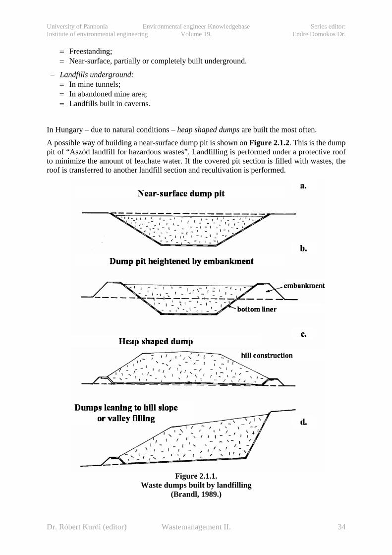
University of Pannonia Environmental engineer Knowledgebase Series editor: Institute of environmental engineering Volume 19. Endre Domokos Dr.
= Freestanding; = Near-surface, partially or completely built underground.
− Landfills underground: = In mine tunnels; = In abandoned mine area; = Landfills built in caverns.
In Hungary – due to natural conditions – heap shaped dumps are built the most often. A possible way of building a near-surface dump pit is shown on Figure 2.1.2. This is the dump pit of “Aszód landfill for hazardous wastes”. Landfilling is performed under a protective roof to minimize the amount of leachate water. If the covered pit section is filled with wastes, the roof is transferred to another landfill section and recultivation is performed.
Figure 2.1.1.
Waste dumps built by landfilling (Brandl, 1989.)
Dr. Róbert Kurdi (editor) Wastemanagement II. 34

University of Pannonia Environmental engineer Knowledgebase Series editor: Institute of environmental engineering Volume 19. Endre Domokos Dr.
metszet
kitű
zési
ala
pvon
al
Alapozási sík
2 %2 %B. 231,052 %
cölöp cölöp
B. 230,19
Út szélének magassága (geodéziai keresztszelvényből)
LERAKÓTÉR
B. 231,13
B. 231,34
B. 231,09B. 231,09 B. 231,11
MEGLÉVŐ ÚT
2 %
B. 224,84 Út szélének magassága (geodéziai keresztszelvényből)B. 224,82 2 %
Alapozási sík
ÁROK
B. 223,94
2 %
B. 225,09
cölöp cölöp
2 %
B. 224,87B. 224,892 %B. 231,09metszet
LERAKÓTÉR
B. 221,00
B. 220,15Földmunkaszint
Hulladéktér határa2 %
2 %
Be s z á l l í t ó i ú t
veszélyes hulladék
Figure 2.1.2.
The cross-section of dump pit of “Aszód landfill for hazardous wastes” (Saubermacher Kft.) with the roof
5.5. Requirements of landfill emplacement 5.5.1. General questions of location selection There are two kinds of requirement-systems by the construction of landfills:
• legislation and • professional requirements.
It must be taken into account, that legislation requirements have also a professional background and professional requirements can be fulfilled according to legislation frameworks. Establishment of a landfill has several phases from project formulation to technical delivery. The different procedure phases are:
• emplacement procedure, • environmental authorization, • construction authorization, • water rights authorization, • technical delivery and acceptance, • occupancy authorization.
The emplacement procedure is optional, not required legally, but it is useful to ascertain about the practicability of the planned landfill, before starting authorization procedure, and the needed tasks of exploration, planning, and impact assessment. The following tasks should be considered:
• Are legislative requirements observable, achievable? • Is the investment economically feasible considering professional and technical
aspects? • Are local residents receptive?
This chapter discusses the emplacement procedure only in professional aspects - because of extent limits – without legal references, but it must be taken into account, that practically most of the professional problems are legally regulated directly or indirectly. Figure 2.2.1. shows the professional procedure of the selection of a suitable location for a landfill.
Dr. Róbert Kurdi (editor) Wastemanagement II. 35
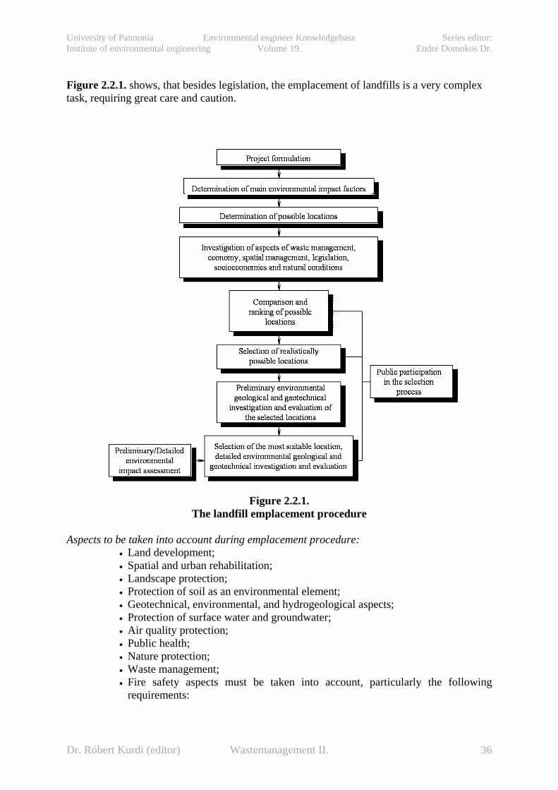
University of Pannonia Environmental engineer Knowledgebase Series editor: Institute of environmental engineering Volume 19. Endre Domokos Dr.
Figure 2.2.1. shows, that besides legislation, the emplacement of landfills is a very complex task, requiring great care and caution.
Figure 2.2.1.
The landfill emplacement procedure
Aspects to be taken into account during emplacement procedure: • Land development; • Spatial and urban rehabilitation; • Landscape protection; • Protection of soil as an environmental element; • Geotechnical, environmental, and hydrogeological aspects; • Protection of surface water and groundwater; • Air quality protection; • Public health; • Nature protection; • Waste management; • Fire safety aspects must be taken into account, particularly the following
requirements:
Dr. Róbert Kurdi (editor) Wastemanagement II. 36

University of Pannonia Environmental engineer Knowledgebase Series editor: Institute of environmental engineering Volume 19. Endre Domokos Dr.
• The distances from the boundary of the landfill to residential and recreation areas, waterways, channels, surface waters, water and other agricultural and urban areas;
• Situation and presence of protection areas of drinking water aquifers; • The location’s sensitivity to contamination (according to current legislation); • The geological and hydrogeological properties of the location; • The risk of flooding, surface subsidence, surface movement (landslides) on the
site; • The protection of the nature or cultural heritage, cultural patrimony in the area.
5.5.2. The environmental geological requirements of landfill emplacement procedures,
suitability criteria An essential criterion of determination of environmental geological requirements is the following: the mineral and the geosynthetic protection must provide together the necessary requirements for waste disposal. For final landfills a minimum natural protection is required in practice, to reassure the local residents, and to provide protection in case of the geosynthetic barrier failure. In this last case of failure, natural protection must protect the environment during the process of the restoration of the geosynthetic protection. Regulations of the Council Directive 1999/31/EC of 26 April 1999 on the landfill of waste are the following: The location of the landfill must take into consideration requirements relating to (1999/31/EC Annex I/1.): a.) The distances from the boundary of the site to residential and recreation areas, waterways,
water bodies and other agricultural or urban sites; b.) The existence of groundwater, coastal water or nature protection zones in the area; c.) The geological and hydrogeological conditions in the area ; d.) The risk of flooding, subsidence, landslides or avalanches on the site; e.) The protection of the nature or cultural patrimony in the area. The following requirements must be taken into account relating to the 22/2001. (X.10.) KÖM Decree about the conditions of landfill: Landfills can be installed in accordance with the aims and tasks of the national and local waste management plan, and the local building code, in compliance with the national urban rehabilitation and building requirements. Landfills can be built only in industrial zones or in peripheral zones. The protective distance between the boundary of the landfill and the existing or in the settlement plan marked residential area, inhabited buildings, protected natural areas, agricultural areas are determined by the environmental inspectorate, and can not be less than:
• 1000 m in case of landfills for hazardous wastes; • 500 m in case of landfills for non-hazardous wastes; • 300 m in case of landfills for inert wastes.
Installation of landfills is prohibited in areas:
• deemed unsuitable in area development and urban rehabilitation plans; • of higher risk of erosion; • of risk of landslides; • of karsts, with broken rock structure, where there are limestone, dolomite, lime-
marl, and dolomite-marl formation on surface and 10 meters under the surface; • of the marked inner, and outer protection zones or hydrogeological “A” protection
areas of the existing, operating or perspective drinking water aquifers, mineral, and spa water aquifers (under separate legislation);
Dr. Róbert Kurdi (editor) Wastemanagement II. 37
University of Pannonia Environmental engineer Knowledgebase Series editor: Institute of environmental engineering Volume 19. Endre Domokos Dr.
• of protected nature; • of protective zones of energy transport pipelines; • in burst areas of existing, operating, or closed underground mines, if consolidation
is not finished and in areas designated for mining; • of higher risk of earthquakes, where the maximal intensity of the earthquake is
VI. on the Medvegyev-Sponhauer-Karnik scale; • of risk of flood, inland water, and areas without remediation; • of higher groundwater levels (the bottom level of the liner system of the landfill
must be 1.0 meters above the possible maximal groundwater level or hydrostatical head.
Installation of landfills for hazardous wastes is prohibited (under separate legislation) on highly sensitive water-quality protection areas (see 33/2000. (III.17.) Gov. Regulation Annex 2/1.). 5.6. Technical requirements of landfill design Subsoil parameters and the liner system are very important parameters by the determination of technical requirements of landfill design. 5.6.1. Subsoil requirements In this chapter criteria of the geological medium, within that the geotechnical eligibility criteria are listed.
A landfill location must fulfil the following geotechnical parameters: a.) Subsoil must be a geological medium of 1,0 meters thick with hydraulic conductivity k ≤ 10-
7 m/s by landfills for inert wastes; 1,0 or 5,0 meters thick with hydraulic conductivity k ≤ 10-9 m/s by landfills for non-hazardous and hazardous wastes or built layers minimum 0,5 meters thick providing equivalent protection. The expression of geological medium includes the surface and the subsurface layers. The subsoil narrower interpretation of the geological medium under the landfill, which can be threatened by the contaminations from the landfill.
b.) Clay mineral content of the subsoil must be at least 10 % by landfills for non-hazardous and hazardous wastes with high adsorption capacity. By landfills for hazardous wastes the location can be particularly suitable if the cation change capacity of the subsoil is T>25 mekv/100 g, and suitable, if it is between 15-25 mekv/100 g. If T<15, the adsorption capacity if the subsoil is disadvantageous, but this is not an exclusion criterion.
c.) The possible maximal groundwater level or hydrostatical head must be more than 1.0 meters below the bottom level of the liner system of non-hazardous landfills, and more than 5.0 meters below the bottom level of the liner system of hazardous landfills. Thus the possible maximal groundwater level or hydrostatical head is expected to be 1.0 or 5.0 meters below the new surface, after excavating the top-soil (humus layer), or if this criterion can not be fulfilled, the bottom of the landfill must be raised.
d.) Organic content of the subsoil can be max. 5%. e.) The strength of the subsoil must be high against the prospective load of the landfill to
prevent the danger of the bottom liner system failure or the stability decrease of the landfill caused by deformations.
f.) The presence of low-strength, poorly consolidated layers near surface are unfavourable, because the excess soil settlement caused by layer compression must be compensated by landfill bottom raise.
Dr. Róbert Kurdi (editor) Wastemanagement II. 38

University of Pannonia Environmental engineer Knowledgebase Series editor: Institute of environmental engineering Volume 19. Endre Domokos Dr.
5.6.2. Structure of the bottom and cover liner system Figures 2.3.1-2.3.5. show the structure of the bottom and cover liner systems of landfills according to the current legislation. Previous legislation required 1.5 meters of cover layer (drainage layer + recultivation layer + topsoil together) above the liner of the mineral barrier. The current legislation decreased the thickness of this cover layer to 1.0 meters.
Figure 2.3.1. Legislation of the structure of the bottom liner system (20/2006.(IV.5.) KvVM Decree, Annex 1.)
Dr. Róbert Kurdi (editor) Wastemanagement II. 39

University of Pannonia Environmental engineer Knowledgebase Series editor: Institute of environmental engineering Volume 19. Endre Domokos Dr.
Figure 2.3.2. Hungarian legislation of the structure of the top (cover) liner system of landfills for inert wastes (20/2006.(IV.5.) KvVM Decree)
Figure 2.3.3. Hungarian legislation of the structure of the top (cover) liner system of landfills for non-hazardous (category B1b) wastes (20/2006.(IV.5.) KvVM Decree)
Figure 2.3.4. Hungarian legislation of the structure of the top (cover) liner system of
landfills for non-hazardous (category B3) wastes (20/2006.(IV.5.) KvVM Decree)
Dr. Róbert Kurdi (editor) Wastemanagement II. 40
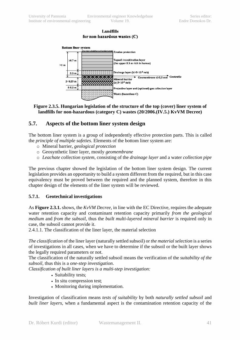
University of Pannonia Environmental engineer Knowledgebase Series editor: Institute of environmental engineering Volume 19. Endre Domokos Dr.
Figure 2.3.5. Hungarian legislation of the structure of the top (cover) liner system of
landfills for non-hazardous (category C) wastes (20/2006.(IV.5.) KvVM Decree)
5.7. Aspects of the bottom liner system design The bottom liner system is a group of independently effective protection parts. This is called the principle of multiple safeties. Elements of the bottom liner system are:
o Mineral barrier, geological protection o Geosynthetic liner layer, mostly geomembrane o Leachate collection system, consisting of the drainage layer and a water collection pipe
The previous chapter showed the legislation of the bottom liner system design. The current legislation provides an opportunity to build a system different from the required, but in this case equivalency must be proved between the required and the planned system, therefore in this chapter design of the elements of the liner system will be reviewed. 5.7.1. Geotechnical investigations As Figure 2.3.1. shows, the KvVM Decree, in line with the EC Directive, requires the adequate water retention capacity and contaminant retention capacity primarily from the geological medium and from the subsoil, thus the built multi-layered mineral barrier is required only in case, the subsoil cannot provide it. 2.4.1.1. The classification of the liner layer, the material selection The classification of the liner layer (naturally settled subsoil) or the material selection is a series of investigations in all cases, when we have to determine if the subsoil or the built layer shows the legally required parameters or not. The classification of the naturally settled subsoil means the verification of the suitability of the subsoil, thus this is a one-step investigation. Classification of built liner layers is a multi-step investigation:
• Suitability tests; • In situ compression test; • Monitoring during implementation.
Investigation of classification means tests of suitability by both naturally settled subsoil and built liner layers, when a fundamental aspect is the contamination retention capacity of the
Dr. Róbert Kurdi (editor) Wastemanagement II. 41
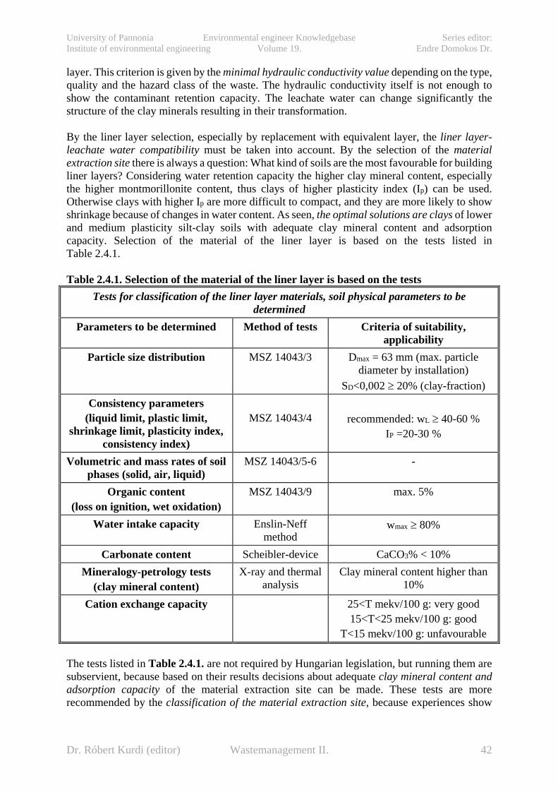
University of Pannonia Environmental engineer Knowledgebase Series editor: Institute of environmental engineering Volume 19. Endre Domokos Dr.
layer. This criterion is given by the minimal hydraulic conductivity value depending on the type, quality and the hazard class of the waste. The hydraulic conductivity itself is not enough to show the contaminant retention capacity. The leachate water can change significantly the structure of the clay minerals resulting in their transformation. By the liner layer selection, especially by replacement with equivalent layer, the liner layer-leachate water compatibility must be taken into account. By the selection of the material extraction site there is always a question: What kind of soils are the most favourable for building liner layers? Considering water retention capacity the higher clay mineral content, especially the higher montmorillonite content, thus clays of higher plasticity index (Ip) can be used. Otherwise clays with higher Ip are more difficult to compact, and they are more likely to show shrinkage because of changes in water content. As seen, the optimal solutions are clays of lower and medium plasticity silt-clay soils with adequate clay mineral content and adsorption capacity. Selection of the material of the liner layer is based on the tests listed in Table 2.4.1.
Table 2.4.1. Selection of the material of the liner layer is based on the tests
Tests for classification of the liner layer materials, soil physical parameters to be determined
Parameters to be determined Method of tests Criteria of suitability, applicability
Particle size distribution MSZ 14043/3 Dmax = 63 mm (max. particle diameter by installation)
SD<0,002 ≥ 20% (clay-fraction) Consistency parameters
(liquid limit, plastic limit, shrinkage limit, plasticity index,
consistency index)
MSZ 14043/4
recommended: wL ≥ 40-60 %
IP =20-30 %
Volumetric and mass rates of soil phases (solid, air, liquid)
MSZ 14043/5-6 -
Organic content (loss on ignition, wet oxidation)
MSZ 14043/9 max. 5%
Water intake capacity Enslin-Neff method
wmax ≥ 80%
Carbonate content Scheibler-device CaCO3% < 10% Mineralogy-petrology tests
(clay mineral content) X-ray and thermal
analysis Clay mineral content higher than
10%
Cation exchange capacity 25<T mekv/100 g: very good 15<T<25 mekv/100 g: good
T<15 mekv/100 g: unfavourable The tests listed in Table 2.4.1. are not required by Hungarian legislation, but running them are subservient, because based on their results decisions about adequate clay mineral content and adsorption capacity of the material extraction site can be made. These tests are more recommended by the classification of the material extraction site, because experiences show
Dr. Róbert Kurdi (editor) Wastemanagement II. 42

University of Pannonia Environmental engineer Knowledgebase Series editor: Institute of environmental engineering Volume 19. Endre Domokos Dr.
that significant differences from the listed suitability criteria means that the liner layer probably can not be built from this material, the required water retention capacity cannot be achieved. The most important part of the qualifying examination is the determination of the hydraulic conductivity. The required water retention capacity of the subsoil and the practicability of the liner layer to be built must be verified, and the latter case the conditions (building parameters) must be given to reach the required water retention capacity.
5.7.1.1. Determination of the hydraulic conductivity The 3 most used method of the determination of the hydraulic conductivity in geotechnical practice are the following:
o in situ tests, o laboratory tests and o calculations based on empirical correlations.
Calculations based on empirical correlations are not suitable to determine the hydraulic conductivity of cohesive soils.
Determination of hydraulic conductivity by laboratory tests The most frequently used method of the determination of the hydraulic conductivity of cohesive soils of low permeability is the laboratory test. While it is cheaper than in situ tests, higher sample numbers can be examined. Based on international experiences the determination of hydraulic conductivity of soils used for liner layers can be performed by both rigid and flexible wall permeameters, but lately only the latter is used. (Figure 2.4.1.)
Figure 2.4.1.
Determination of the hydraulic conductivity of clays in triaxial cell
Dr. Róbert Kurdi (editor) Wastemanagement II. 43

University of Pannonia Environmental engineer Knowledgebase Series editor: Institute of environmental engineering Volume 19. Endre Domokos Dr.
The triaxial cell (the one used for shear tests) or the modified triaxial cell is used by this test method where the sample is surrounded by a rubber membrane, and this membrane is pushed to the sample by a cell pressure provided by the liquid (mostly water) in the cell. The advantages of the application of flexible wall permeameters (over the application of rigid wall permeameters) are: − sidewall leakage (between the sample and the membrane) can be prevented by adequate
sidewall pressure; − permeability tests can be performed by real stress conditions; − the saturation of the sample (fundamental requirement of the test) can be provided by the
so-called "back pressure" technique.
Determination of the hydraulic conductivity on site The field determination of the hydraulic conductivity has several measurement problems. Most of the methods used in hydrogeological practice, pumping tests, infiltration tests, and overpressure injection) cannot be used in this case. The best and most widely used method in environmental geotechnics is the so-called pipe-type infiltrometer test (Figure 2.4.2.). The tests can be performed on the soil surface (after the removal of the topsoil) or in a pit.
Figure 2.4.2. The field determination of the hydraulic conductivity of the bottom liner system of landfills by pipe-type infiltrometer (BRANDL, 1989.)
5.7.1.2. The building of liner layer, construction standards
Dr. Róbert Kurdi (editor) Wastemanagement II. 44

University of Pannonia Environmental engineer Knowledgebase Series editor: Institute of environmental engineering Volume 19. Endre Domokos Dr.
The construction parameters (see on Figure 2.4.3.) determined by laboratory tests must be controlled and refined by test compactions before construction starts. Test compactions provide final answers about the following questions: − Can the required water retention capacity be provided based on preliminary suitability tests? − What kind of compaction work (machine, number of operations) is needed to reach the
required values?
Figure 2.4.3. Determination of hydraulic conductivity, shear strength, and construction
parameters suitable also in aspects of shrinkage (DANIEL, 1993.)
The construction of the mineral liner layer can start only after tests compaction of the material deemed suitable based on laboratory tests. The compactness of the liner layer determines its hydraulic conductivity, thus satisfactory results can be achieved only by careful constructions, taking into account those requirements. Compliance of the following is required: − Compaction must be performed one by one on every single layer, the maximum thickness
(d) of the layers in compacted condition: 20 cm < d < 25 cm. In case of optimum conditions larger than 25 cm layer thickness (max. 30 cm) can be allowed. (Optimum conditions are: adequate particle size analysis, favourable water content, on site mixing plantation, effective compaction machines.)
− The water content at the construction must be some percents higher than the optimal water content determined by the Proctor test (the construction must be performed on the wet side of the Proctor curve), because it results in favourable clay structures and lower hydraulic conductivity (Figure 2.4.4.). The criterion of favourable construction water content:
Dr. Róbert Kurdi (editor) Wastemanagement II. 45
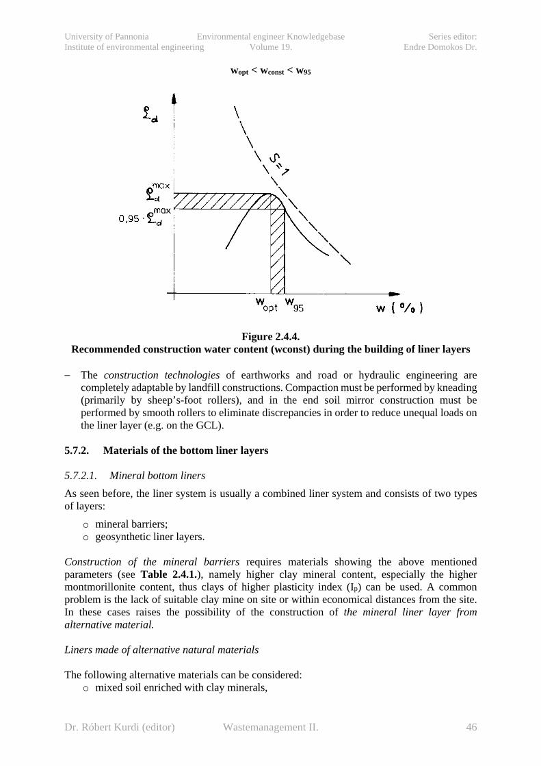
University of Pannonia Environmental engineer Knowledgebase Series editor: Institute of environmental engineering Volume 19. Endre Domokos Dr.
wopt < wconst < w95
Figure 2.4.4.
Recommended construction water content (wconst) during the building of liner layers
− The construction technologies of earthworks and road or hydraulic engineering are completely adaptable by landfill constructions. Compaction must be performed by kneading (primarily by sheep’s-foot rollers), and in the end soil mirror construction must be performed by smooth rollers to eliminate discrepancies in order to reduce unequal loads on the liner layer (e.g. on the GCL).
5.7.2. Materials of the bottom liner layers 5.7.2.1. Mineral bottom liners As seen before, the liner system is usually a combined liner system and consists of two types of layers:
o mineral barriers; o geosynthetic liner layers.
Construction of the mineral barriers requires materials showing the above mentioned parameters (see Table 2.4.1.), namely higher clay mineral content, especially the higher montmorillonite content, thus clays of higher plasticity index (Ip) can be used. A common problem is the lack of suitable clay mine on site or within economical distances from the site. In these cases raises the possibility of the construction of the mineral liner layer from alternative material. Liners made of alternative natural materials The following alternative materials can be considered:
o mixed soil enriched with clay minerals,
Dr. Róbert Kurdi (editor) Wastemanagement II. 46

University of Pannonia Environmental engineer Knowledgebase Series editor: Institute of environmental engineering Volume 19. Endre Domokos Dr.
o mixed soil enriched with clay minerals and polymer additives, o geosynthetic clay liners.
The legislation requires equivalency of the 2 different liner system, thus equal contaminant transport as a criterion of the application of alternative materials. Primarily the bentonite-soil mixtures can be used as equivalent mineral liner layers. Their advantages are the homogeneous material quality, clay mineral content and easy compressibility. Disadvantages are the erosion sensitivity, the sensitivity of the compliance of technological requirements and the sensitivity of construction water content (HORN, 1986; 1988; 1989; BRANDL, 1989; CHAPIUS, 1990a; 1990b.). Hungarian and international laboratory experiences show that only 6-8 % bentonite addition is enough to reach the k < 10-9 m/s hydraulic conductivity. The so-called GCL-s (geosynthetic clay liners) appeared at the end of the 80s, and has an increasing role since then in the construction of mineral liners. The GCL abbreviation is used in international literature, and in practice, based on the name Geosynthetic Clay Liner. Geosynthetic clay liners consist of a bentonite layer between two geosynthetic carrier (geotextile or geomembrane). The thickness of the bentonite layer is usually 5-10 mm, and their weight changes between 3-5 kg/m2 based on the quantity of bentonite load. Bentonite powder (and if needed binder also as additive) is placed between the geosynthetics. The main advantage of their application as a liner is the property of the bentonite to swell after water absorption (hydration), but the tying of the two bounding geotextile by stitch bonding or needle punching inhibits the growth of volume, resulting in a thin but watertight layer. The typical hydraulic conductivity of GCLs is in the range of 1210 10510 −− ×− m/s. The most important parameter of GCLs is their hydraulic conductivity. A summary of results of the hydraulic conductivity of GCL-s is shown on Figure 2.4.5.
Figure 2.4.5.
Summary of results of the hydraulic conductivity tests of GCLs (ESTORNELL-DANIEL, 1992.; University of Miskolc, 2002.; GEOSZABO, 2005.)
Geosynthetic clay liners have several advantageous properties compared to the compacted clay liners. Specifically noted are the following:
Dr. Róbert Kurdi (editor) Wastemanagement II. 47

University of Pannonia Environmental engineer Knowledgebase Series editor: Institute of environmental engineering Volume 19. Endre Domokos Dr.
o the application of GCL-s is less dependent on local facilities; o the construction of GCLs requires no control tests on site (e.g. permeability); o the construction of GCLs requires simpler machines; o the progress of construction is faster and less dependent on the weather; o smaller areas can be easily insulated; o GCLs are less sensitive on settlements, on differences between settlements, on freezing
and on erosion; o easier maintainability; o lower construction cost.
However there are some disadvantages of the application of geosynthetic clay liners compared to compacted clay liners:
o greater vulnerability; o smaller adsorption capacity; o smaller breakthrough time in case of solutions; o greater diffusion flux.
As seen above, disadvantages appear in the field of contaminant retention capacity, which is due to the small layer thickness primarily. Based on this GCLs can be stated to be appropriate as a complementary element, if equivalency is proved, but cannot be used alone as bottom liners. They can be used also by the embankments, where the contamination load is significantly lower than it is on the bottom liner. Their most important application is in the field of cover liner systems based on their hydraulic equivalency. The mixture soils (mineral barriers) enriched with polymer additives contain usually a polymer composition treated as commercially confidential. The best known polymer-soil composition is the so-called TRISOPLAST liner material (TD Umwelttechnik GmbH & Co. KG, Wentdorf), with a composition of the following mass rates:
≤ 89.1% mineral material (e.g. sand); ≥ 10.7 % bentonite; > 0.2 % polymer.
5.7.2.2. Geosynthetic liner layers (geomembranes) Membrane liners must withstand several types of loads (mechanical, physico-chemical and biological) as well as the mineral barriers for a required period of time. Inadequate sizing and material selection leads to direct failure (tearing, perforation) as an effect of mechanical stress, or to continuous ageing as en effect of physico-chemical and biological loads, with the occurrence of changes in mechanical properties and water tightness. Qualification of geomembranes is performed by tests based on standards, the limit values of the retention capacity of the foils available for sale are guaranteed by the manufacturers. Every single geomembrane must be qualified by an independent institute authorized for these tests. The wide-ranging tests are standardized in almost every manufacturer’s country. During the qualifying tests the determination of the following parameters must be performed:
• size, • nominal thickness, • difference from nominal thickness, • density, • melt index, flow index, • water absorption, • steam and gas permeability (transmission), • tensile strength (longitudinal and transverse),
Dr. Róbert Kurdi (editor) Wastemanagement II. 48
University of Pannonia Environmental engineer Knowledgebase Series editor: Institute of environmental engineering Volume 19. Endre Domokos Dr.
• elongation at break, • tear strength (longitudinal and transverse), • punch resistance, point pressure resistance, • uniaxial tensile force of 5% elongation (longitudinal and transverse), • possible expansion due to heat (longitudinal and transverse), • resistance to cold, behaviour at cold folding • weld strength, • weather resistance, • biological resistance, • friction between the soil and the geomembrane.
Currently the most widely used type of geomembrane is the so-called HDPE (high density polyethylene) in Hungary and worldwide also. The advantage of the application of HDPE geomembranes in bottom liner systems is clear, but in cover liner systems geomembranes with better deformation properties (triaxial elongation) can be used. Geomembrane types used in everyday practice besides HDPE are the following: PVC, PVC, CSPE (chlorosulphonated polyethylene, commercial name: Hypalon), LDPE (low density polyethylene), EPDM (ethylene propylene diene monomer).
Chemical resistance of geomembranes, compatibility issues Chemical resistance of geomembranes must be proved by certain. The composition of the test liquid depends on the possible load.
Selection of the suitable geomembrane The first step of the selection is the examination of the chemical resistance, the compatibility. The best type of geomembrane must be chosen for the certain waste type or leachate water. The second step is the selection of an adequate geomembrane to bear the possible mechanical loads. The third step is to determine the required size of the geomembrane within the above determined geomembrane type based on the actual and the expected loads. The thickness of the geomembrane is determined by the mechanical loads primarily. The relevant government decree requires at least 2.5 mm thickness. In critical cases higher thickness of geomembranes must be considered. The process of scaling:
• the significant stresses are determined for the critical cross-section: waste loads, net weight, friction forces,
• the required cross section (geomembrane) thickness can be determined based on the strength parameters of the geomembrane (calculated from the resultant stress).
5.7.3. Structure and sizing of the leachate collection system An integral part of the bottom liner system is an effective system to collect, drain, and control the leachate water. This is called collectively the leachate collection system, a system consisting of several autonomous elements.
Dr. Róbert Kurdi (editor) Wastemanagement II. 49

University of Pannonia Environmental engineer Knowledgebase Series editor: Institute of environmental engineering Volume 19. Endre Domokos Dr.
The leachate collection system between the waste and the first liner layer consists of at least two layers. The drainage system is installed above the liner layer, and this is isolated from the waste by the filtering-protective layer. This has dual function: first, facilitating the infiltration of the leachate into the collection and drainage system, and on the other hand to prevent the clogging of this system with the fine particles from the waste. This layer must be engineered also either made of natural material (loose granular soil) or synthetic material (technical or geotextile). The drainage system must be calibrated also on the maximal hydraulic gradient to be able to lead the leachate without back damming. The second drainage layer, if exists is built under the first liner layer and has dual function also: primary is the controlling function (indicating the failures of the liner system) and secondary is the collection-drainage function. The requirements of the construction of leachate collection system according to the 20/2006.(IV.5.) KvVM Decree Annex 1. Point 1.3.3. are collected in Table 2.4.3. Table 2.4.3. The requirements of the construction of leachate collection system
Landfills for inert wastes
Landfills for non-hazardous
wastes
Landfills for hazardous wastes Upper drainage
layer Second drainage and control layer
Thickness (m) 0,3-0,5 0,3-0,5 0,3-0,5 0,3 Material 16/32 or
24/40 graded gravel
16/32 or 24/40 graded gravel
16/32 or 24/40 graded gravel
_
Required hydraulic
conductivity k (m/s)
>10-3 >10-3 >10-3 >10-3
If the landfill provides no risk on the environment (geological medium, surface water, groundwater) based on preliminary surveys, thus the thickness of the drainage system, the distance between drainage pipes, the slope conditions are determined by the accepted sizing method, than there is the possibility to choose the smaller thickness. Thinner layers than 0.5 meters must be sized. By the design of the drainage system the following issues must be taken into account to fulfil the related decree and the requirement of economical construction:
o to provide long-term efficiency of drainage ; o the selection of the suitable material; o distance between drainage pipes providing effective drainage − selection of the layer
thickness-slope of layer relation.
5.7.3.1. Design of the filtering- protective layer The filtering-protective layer, if exists, is usually between the waste and the drainage layer above the upper geomembrane, but in simple cases the drainage layer can be enough. This filtering-protective layer has two important tasks:
Dr. Róbert Kurdi (editor) Wastemanagement II. 50

University of Pannonia Environmental engineer Knowledgebase Series editor: Institute of environmental engineering Volume 19. Endre Domokos Dr.
• to provide access for the leachate into do drainage layer; • to prevent the clogging of the drainage layer with the smaller particles from the
waste. The material of this filtering-protective layer can be:
• mineral and • synthetic (geotextile).
The filtering layer made of natural material is built of sand, sandy gravel or gravel of a certain particle size distribution in accordance with the so-called filter criterion. The particle size distribution of the filtering layer is determined basically by the particle size and particle size distribution of the waste, and any well-tried filter criterion can be applied (criterion for well screens, drains). The classic solution is Therzaghi’s filter criterion:
dD4
dD
15h
15sz
85h
15sz <<
It says, that the particle size distribution of the filtering layer is sufficient, if the particle size at 15 % weight percent on the particle size distribution curve of the filtering layer (D15sz) is at least four times larger than particle size at 15 % weight percent on the particle size distribution curve of the waste (d15h), but at least four times smaller than the particle size at 85 % weight percent on the particle size distribution curve of the waste (d85h). There are several other methods with the same idea, namely, that the particle size curve of the filtering layer must be nearly parallel to the particle size distribution curve of the layer to be protected. The well-tried American Recommendation is based on the same principle (EPA, 1985.):
15sz
85h
Dd
5<
50sz
50h
Dd
25<
4Dd
2015sz
15h< <
If the particle size distribution of the waste (or the layer below) is very smooth, (e.g. landfills for fly ash or other homogeneous materials), so U < 1.5, than
15sz
85h
Dd
6<
By uneven particle size distributions (U > 4):
4Dd
4015sz
15h< <
The main problem of the application of these filter criteria is, that the actual particle size distribution of the waste to be deposited is usually not known, and the particle size of some types of waste is widely varying. 5.7.3.2. The selection of geotextiles The filtering layer is usually only a geotextile above the drainage layer, which has to be designed in order of the maintainability of the leachate collection system.
Dr. Róbert Kurdi (editor) Wastemanagement II. 51
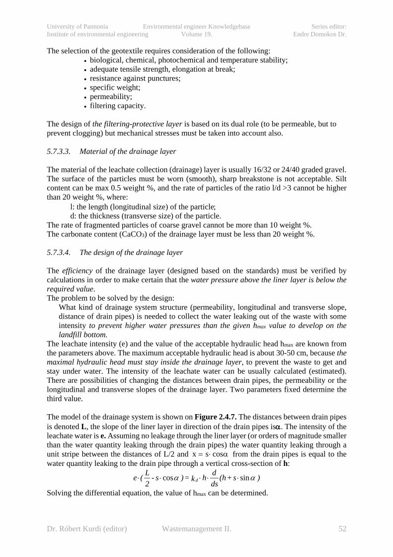
University of Pannonia Environmental engineer Knowledgebase Series editor: Institute of environmental engineering Volume 19. Endre Domokos Dr.
The selection of the geotextile requires consideration of the following: • biological, chemical, photochemical and temperature stability; • adequate tensile strength, elongation at break; • resistance against punctures; • specific weight; • permeability; • filtering capacity.
The design of the filtering-protective layer is based on its dual role (to be permeable, but to prevent clogging) but mechanical stresses must be taken into account also. 5.7.3.3. Material of the drainage layer The material of the leachate collection (drainage) layer is usually 16/32 or 24/40 graded gravel. The surface of the particles must be worn (smooth), sharp breakstone is not acceptable. Silt content can be max 0.5 weight %, and the rate of particles of the ratio l/d >3 cannot be higher than 20 weight %, where:
l: the length (longitudinal size) of the particle; d: the thickness (transverse size) of the particle.
The rate of fragmented particles of coarse gravel cannot be more than 10 weight %. The carbonate content (CaCO3) of the drainage layer must be less than 20 weight %. 5.7.3.4. The design of the drainage layer The efficiency of the drainage layer (designed based on the standards) must be verified by calculations in order to make certain that the water pressure above the liner layer is below the required value. The problem to be solved by the design:
What kind of drainage system structure (permeability, longitudinal and transverse slope, distance of drain pipes) is needed to collect the water leaking out of the waste with some intensity to prevent higher water pressures than the given hmax value to develop on the landfill bottom.
The leachate intensity (e) and the value of the acceptable hydraulic head hmax are known from the parameters above. The maximum acceptable hydraulic head is about 30-50 cm, because the maximal hydraulic head must stay inside the drainage layer, to prevent the waste to get and stay under water. The intensity of the leachate water can be usually calculated (estimated). There are possibilities of changing the distances between drain pipes, the permeability or the longitudinal and transverse slopes of the drainage layer. Two parameters fixed determine the third value. The model of the drainage system is shown on Figure 2.4.7. The distances between drain pipes is denoted L, the slope of the liner layer in direction of the drain pipes isα. The intensity of the leachate water is e. Assuming no leakage through the liner layer (or orders of magnitude smaller than the water quantity leaking through the drain pipes) the water quantity leaking through a unit stripe between the distances of L/2 and x s= ⋅ cosα from the drain pipes is equal to the water quantity leaking to the drain pipe through a vertical cross-section of h:
)s+(hdsdhk=)s-
2L(e d αα sincos ⋅⋅⋅⋅⋅
Solving the differential equation, the value of hmax can be determined.
Dr. Róbert Kurdi (editor) Wastemanagement II. 52
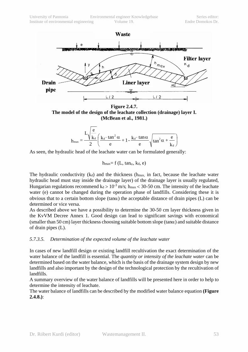
University of Pannonia Environmental engineer Knowledgebase Series editor: Institute of environmental engineering Volume 19. Endre Domokos Dr.
Figure 2.4.7.
The model of the design of the leachate collection (drainage) layer I. (McBean et al., 1981.)
maxtan tan
tanh =L e
k2
ke
+ 1- ke
+ ek
d d d 2
d
⋅ ⋅
2 α αα
As seen, the hydraulic head of the leachate water can be formulated generally:
hmax= f (L, tanα, kd, e)
The hydraulic conductivity (kd) and the thickness (hmax, in fact, because the leachate water hydraulic head must stay inside the drainage layer) of the drainage layer is usually regulated, Hungarian regulations recommend kd > 10-3 m/s; hmax < 30-50 cm. The intensity of the leachate water (e) cannot be changed during the operation phase of landfills. Considering these it is obvious that to a certain bottom slope (tanα) the acceptable distance of drain pipes (L) can be determined or vice versa. As described above we have a possibility to determine the 30-50 cm layer thickness given in the KvVM Decree Annex 1. Good design can lead to significant savings with economical (smaller than 50 cm) layer thickness choosing suitable bottom slope (tanα) and suitable distance of drain pipes (L). 5.7.3.5. Determination of the expected volume of the leachate water In cases of new landfill design or existing landfill recultivation the exact determination of the water balance of the landfill is essential. The quantity or intensity of the leachate water can be determined based on the water balance, which is the basis of the drainage system design by new landfills and also important by the design of the technological protection by the recultivation of landfills. A summary overview of the water balance of landfills will be presented here in order to help to determine the intensity of leachate. The water balance of landfills can be described by the modified water balance equation (Figure 2.4.8.):
Dr. Róbert Kurdi (editor) Wastemanagement II. 53
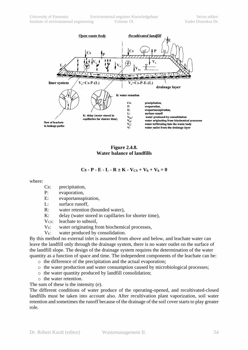
University of Pannonia Environmental engineer Knowledgebase Series editor: Institute of environmental engineering Volume 19. Endre Domokos Dr.
Figure 2.4.8.
Water balance of landfills
Cs - P - E - L - R ± K - VCS + Vb + Vk = 0 where:
Cs: precipitation, P: evaporation, E: evaportansspiration, L: surface runoff, R: water retention (bounded water), K: delay (water stored in capillaries for shorter time), VCS: leachate to subsoil, Vb: water originating from biochemical processes, Vk: water produced by consolidation.
By this method no external inlet is assumed from above and below, and leachate water can leave the landfill only through the drainage system, there is no water outlet on the surface of the landfill slope. The design of the drainage system requires the determination of the water quantity as a function of space and time. The independent components of the leachate can be:
o the difference of the precipitation and the actual evaporation; o the water production and water consumption caused by microbiological processes; o the water quantity produced by landfill consolidation; o the water retention.
The sum of these is the intensity (e). The different conditions of water produce of the operating-opened, and recultivated-closed landfills must be taken into account also. After recultivation plant vaporization, soil water retention and sometimes the runoff because of the drainage of the soil cover starts to play greater role.
Dr. Róbert Kurdi (editor) Wastemanagement II. 54
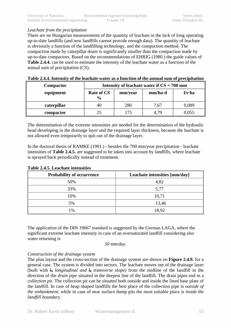
University of Pannonia Environmental engineer Knowledgebase Series editor: Institute of environmental engineering Volume 19. Endre Domokos Dr.
Leachate from the precipitation There are no Hungarian measurements of the quantity of leachate in the lack of long operating up-to-date landfills (and new landfills cannot provide enough data). The quantity of leachate is obviously a function of the landfilling technology, and the compaction method. The compaction made by caterpillar dozer is significantly smaller than the compaction made by up-to-date compactors. Based on the recommendations of EHRIG (1980.) the guide values of Table 2.4.4. can be used to estimate the intensity of the leachate water as a function of the annual sum of precipitation (CS). Table 2.4.4. Intensity of the leachate water as a function of the annual sum of precipitation
Compactor Intensity of leachate water if CS = 700 mm equipment Rate of CS
% mm/year mm/ha·d l/s·ha
caterpillar 40 280 7,67 0,089 compactor 25 175 4,79 0,055
The determination of the extreme intensities are needed for the determination of the hydraulic head developing in the drainage layer and the required layer thickness, because the leachate is not allowed even temporarily to quit out of the drainage layer. In the doctoral thesis of RAMKE (1991.) - besides the 700 mm/year precipitation - leachate intensities of Table 2.4.5. are suggested to be taken into account by landfills, where leachate is sprayed back periodically instead of treatment. Table 2.4.5. Leachate intensities
Probability of occurrence Leachate intensities [mm/day] 50% 4,82 33% 5,77 10% 10,71 5% 13,46 1% 18,92
The application of the DIN 19667 standard is suggested by the German LAGA, where the significant extreme leachate intensity in case of an oversaturated landfill considering also water returning is
50 mm/day.
Construction of the drainage system The plan layout and the cross-section of the drainage system are shown on Figure 2.4.9. for a general case. The system is divided into sectors. The leachate moves out of the drainage layer (built with ih longitudinal and ik transverse slope) from the midline of the landfill in the direction of the drain pipe situated in the deepest line of the landfill. The drain pipes end in a collection pit. The collection pit can be situated both outside and inside the lined base plate of the landfill. In case of heap shaped landfills the best place of the collection pipe is outside of the embankment, while in case of near surface dump pits the most suitable place is inside the landfill boundary.
Dr. Róbert Kurdi (editor) Wastemanagement II. 55

University of Pannonia Environmental engineer Knowledgebase Series editor: Institute of environmental engineering Volume 19. Endre Domokos Dr.
Figure 2.4.9.
Construction of the drainage system (RAMKE, 1991.)
The sizes and parameters commonly used by drainage system construction are shown on Figure 2.4.9.: Transverse slope (ik): ............................................................ ≥ 3% Longitudinal slope (ih): ....................................................... 1-2% Distance of collection pits: In transverse direction (lk): ............................................ 30-50 m In longitudinal direction (lh): ......................................... max. 300 m Parameters of the drainage layer: Thickness: ...................................................................... 30-50 cm Hydraulic conductivity: ................................................. k ≥ 10-3 m/s Material: ........................................................................ 16/32 or 24/50 graded filter gravel Diameter of the drain pipe: .................................................. 200-300 mm The recommended thickness of the filtering layer must be built also above the drain pipe. The construction method is shown on Figure 2.4.10.:
Dr. Róbert Kurdi (editor) Wastemanagement II. 56

University of Pannonia Environmental engineer Knowledgebase Series editor: Institute of environmental engineering Volume 19. Endre Domokos Dr.
Figure 2.4.10.
Construction method of drain pipes (DIN 19667, 1990.)
5.8. Recultivation of landfills 5.8.1. General issues of the recultivation of landfills Most of the landfills were constructed before 1995-2000 in Hungary. These usually small landfills are to be closed soon and during their recultivation (the construction of their cover liner system) a sensible compromise must be reached for both legislative and economical reasons. The degree of compromise depends on the results of the review and the risk analysis, and the protection of the environment has primary importance. More than 2000 landfills were closed until the 16th of June 2009, where: − There is no need for a landfill because of the creation of the regional network; − The liner system cannot be modified according to the requirements of the new legislation; − The operator or the owner of the landfill does not want to modify the liner system according to the requirements of the new legislation. Basic concepts according to the 92/2007 (XI.28.) KvVM Decree about the modification of the 20/2006 (IV.5.) KvVM Decree about landfills and rules and criteria about landfills:
o Recultivation: the reduction of the environmental risk of the closed landfill or part of the landfill in order to prepare for new land use by closure, construction of technical protection and monitoring system or by gathering the waste up and fitting the landfill into landscape.
o Aftercare: Complex activities after the recultivation of the landfill, which includes the operation of the monitoring system, the management of the drainage and gas-collection system, as well as the necessary maintenance work.
o Fit into the landscape: The functional and aesthetical environment forming of the facility considering the landscape features.
Dr. Róbert Kurdi (editor) Wastemanagement II. 57
University of Pannonia Environmental engineer Knowledgebase Series editor: Institute of environmental engineering Volume 19. Endre Domokos Dr.
Legislation of the landfill recultivation and aftercare: o The recultivation and aftercare of the landfill can be performed if the legislation allows
it without any other action. The recultivation and aftercare of the landfill or part of the landfill can be authorized by the Inspectorates – involving the professional statutory authority.
o The licence application shall include the recultivation plan according to the 4th. Annex of the Decree.
o If an environmental review was completed before the authorization of the recultivation and aftercare of the landfill to explore the impact of the landfill on the environment and there are no changes in the condition of the landfill, the recultivation plan must be worked out based on this environmental review according to the 4th Annex of the Decree.
o If the Inpsectorate initiates proceedings ex officio on the recultivation of the landfill or part of the landfill, the operator of the landfill or the owner of the site is obliged to make an environmental review. The recultivation plan must be worked out based on this environmental review according to the 4th Annex of the Decree.
o The Inspectorate provides decisions on the environmental requirements of the recultivation and aftercare of the landfill, which should include the following: Technological requirements of the landfill recultivation. Requirements of the technical design of the recultivation. Types and quantity of materials useful for recultivation. Aftercare time period according to the 4th Annex of the Decree. Name of the operator during aftercare.
o The time period, when the landfill can have a risk on to the environment must be considered in determining the aftercare period.
o In the aftercare period the operator has the responsibility for the maintenance, observation and control of the recultivated landfill according to the 3rd Annex of the Decree. The operator must notify the Inspectorate about any detected pollution during aftercare in 8 days after detection.
o The landfill must be covered by a temporal cover system until the stabilization of the biological degradable organic compound of the waste body, and there is a risk of intensive gas formation and landfill settlement. The final cover system can be built only when the stabilization in the waste body completed.
It follows that the recultivation by closure can be performed in one or two stages depending on the stabilization process. In the first case, the final cover system is built immediately, in the last case a temporal cover system precedes. Part processes of recultivation and aftercare:
o The preparation and the authorization of the design documentation of the recultivation and aftercare.
o The construction of the temporal and final cover system of the landfill. o The construction and the operation of the gas-collection and treatment system. o The construction and the operation of the leachate and rainwater collection system. o The construction and the operation of the monitoring system required in the aftercare
period.
Dr. Róbert Kurdi (editor) Wastemanagement II. 58
University of Pannonia Environmental engineer Knowledgebase Series editor: Institute of environmental engineering Volume 19. Endre Domokos Dr.
o Shaping of the waste body, compaction of the surface layers, construction of slopes, fit into landscape, further use taken into account.
o Demolition of the equipments and structures if no further use planned, fitting their site into landscape.
o Maintenance and conservation work during the entire aftercare. o Completion of aftercare. o Complying with the reporting obligation.
Requirements above must be applied depending on the waste composition, the degree of preparedness of the existing technical facilities and whether the recultivation must be performed on the whole landfill or only on a part of it. The construction of the cover system contains the cover of the landfill slopes, if needed. The 92/2007 (XI.28.) KvVM Decree about The content requirements of the design documentation of recultivation and aftercare Annex 4th requires:
o The presentation of the impact of the landfill on the environmental elements, especially on the surface water and the groundwater, and the geological medium in the immediate vicinity, and the risk of environmental pollution.
o The scheduling of the operation of the landfill (temporary and/or final). o The structure and the method of construction of the cover liner system (slope directions
must be presented on site plans (layouts) with contour elevations and on cross-sections). o The description of the construction, operation and maintenance of the monitoring
system required during the aftercare period. o The description of the gas treatment of the landfill. o The description of the treatment of the leachate and rainwater. o The description of the shaping of the waste body, compaction of the surface layers,
construction of slopes, fit into landscape o The plans about the demolition of the equipments and structures if no further use
planned, fitting their site into landscape o The content, method and scheduling of the maintenance and conservation work during
the entire aftercare. o The method and date of completion of aftercare. o The data content and method of reporting.
The method of the selection of the suitable recultivation is summarized on Figure 2.5.1.
Dr. Róbert Kurdi (editor) Wastemanagement II. 59

University of Pannonia Environmental engineer Knowledgebase Series editor: Institute of environmental engineering Volume 19. Endre Domokos Dr.
Figure 2.5.1. Selection of the recultivation method
5.8.2. The temporal cover liner system of landfills The construction of the temporal cover liner system of landfills is regulated by the 20/2006. (IV.5.) KvVM Decree Annex 4th. When reaching a certain height of waste, the landfill or part of it has to be covered. The process of the waste consolidation does not stop at this closure point, the process of waste degradation and the mechanical consolidation proceeds, thus large amounts of leachate water and significant surface movements (settlements) must be anticipated. In order to:
provide optimal conditions for waste degradation, prevent the functional failure of the final cover system because of the unequal
settlements, a temporal cover system should be built in the first phase of the closure. By the landfills for inert wastes, or by other landfills, where significant degradation or consolidation of the waste body is not expected, the construction of the temporal cover system is not required. The temporal cover system must be operated until the biological and mechanical stabilization or consolidation ends in the waste body. Requirements of the temporal cover system:
the materials used for the cover must bear the expected movements without failure and significant decrease in efficiency;
helps to minimize leachate; prevents the infiltration of higher amount of rainwater than desirable into the landfill; allows the controlled treatment of landfill-gas.
Dr. Róbert Kurdi (editor) Wastemanagement II. 60
University of Pannonia Environmental engineer Knowledgebase Series editor: Institute of environmental engineering Volume 19. Endre Domokos Dr.
It seems to be a contradiction that it has to prevent the infiltration of precipitation into the waste body (minimal leachate), but allow to infiltrate enough water for the waste degradation. In fact, to meet this latter function is more difficult, and this is the reason why there is no general suggested layer sequence for every single case. Each landfill requires unique design, unique layers. Options to be taken into account by the material selection of the temporal cover system:
• required water retention capacity; • time duration; • wind direction; • frost sensitivity; • danger of erosion; • suitability for installation (bottom, slope); • reusability, integrability to the final cover system; • degradability; • costs.
Materials to be considered by the construction of alternative cover systems: o Liners made of mineral materials; o Geomembranes; o GCLs.
5.8.3. Legislation of the final cover system of landfills Mostly mineral and geosynthetic cover liner layers (geomembranes already known as bottom liners) are considered as final closure for landfills. Elements of the final cover system (in direction from the waste to the surface):
• Protective layer, • Gas-collection (gas-discharging) layer, • Liner layers:
o mineral, o geosynthetic,
• drainage layer, • filtering layer, • recultivation layer, • topsoil.
The following must be taken into account by the cover system design: - regulations of earthworks, installations, compactions; - adequate slope stability; - adequate geomembrane and getoextile strength characteristics against mechanical
loads; - resistance against chemical loads (leachate, landfill gas, gas condensates); - resistance against biological loads (plant roots, rodents, microbial transformation
processes); Considering the “The Council Directive 1999/31/EC on the landfill of waste" and "The 2003/33/EC criteria and procedures for the acceptance of waste at landfills directive", the 20/2006. (IV.5.) KvVM Decree about landfills and rules and criteria about landfills” contains the regulation of the cover systems of landfills, as shown on Figures 2.3.2. – 2.3.5.
Aspects of the design of the cover system
Dr. Róbert Kurdi (editor) Wastemanagement II. 61

University of Pannonia Environmental engineer Knowledgebase Series editor: Institute of environmental engineering Volume 19. Endre Domokos Dr.
Protective and gas-collection layer Under the liner layer a protective, and if needed a gas-collection layer is planned. The material of the protective layer should be a homogeneous, granular, gas permeable soil; the thickness of this layer must be at least 30 cm. To use the protective layer as a gas-collection layer is prohibited. Granular soils with low carbonate content (CaCO3), blast furnace slag or slag from waste incinerator plants can be used. The material of the gas-collection layer has to be gas permeable soil with low carbonate content (CaCO3<10%), with smooth particle size distribution, stabile by the given slope conditions. Slope stability analysis must be performed by the conventional methods (JANBU, BISHOP, planar slide). If the remaining gas content is low, the upper limit of carbonate content is 25 %.
The mineral barrier If a mineral barrier is required (B1b; B3; C type landfills) it has to be built in two parts (2×25 cm thickness). The required hydraulic conductivity in case of landfills type B1b and B3: k≤5×10⁻⁹ m/s, in case of landfills type C: k≤10-9 m/s. The construction of the mineral barrier can be performed parallel to the direction of the slope up to 1:2.5 of slope, but in case of larger slopes the construction of this layer is critical, the layer must be reinforced (e.g. geogrid) or alternative solutions must be preferred. Contrary to the experiences by the bottom liner systems, the construction and the compaction of the cover liner layers must be performed on the dry side of the Proctor curve (wconst < wopt), by Trρ>95% relative compactness condition (see Figure 2.5.2.).
Figure 2.5.2.
Determination of the required water content of the mineral barrier at the construction of the cover liner system
Criteria to be taken into account by the selection of the mineral barrier:
• water retention capacity, • watertightness, • gas insulating capacity, • mechanical resistance, • slope stability,
Dr. Róbert Kurdi (editor) Wastemanagement II. 62

University of Pannonia Environmental engineer Knowledgebase Series editor: Institute of environmental engineering Volume 19. Endre Domokos Dr.
• deformation security, • resistance to erosion, • durability, • resistance to gas condensates, • resistance to change of temperature, • resistance to micro organisms, fungi, • resistance to plant roots, • construction, • construction according to regulations, • mechanical resistance during the construction phase, • resistance to weather changes, • verifiability, • reparability.
The geomembrane The required thickness of the geomembrane by final covers is 2.5 mm by landfills type C. The lifetime of geomembranes can be more than 100 years if properly constructed. Requirements of the geomembrane selection:
• water retention capacity, • watertightness, • gas insulating capacity, • mechanical resistance, • roughened, structured geomembranes are stabile up to 1:2,5 of slopes, • favourable deformation security, at least 3% elongation without break, • geomembranes of favourable multi-axial elongation (LDPE, EPDM) should be
applied to bear unequal settlements, • durability, • certified geomembranes should be resistant to relevant chemical materials and gas
condensates, • resistance to micro organisms, fungi, • resistance to plant roots, • construction, • construction according to regulations, • resistance to external loads (application of protective layer if needed) • resistance to weather changes (no laying under 5°C, resistance to solar radiation) • verifiability (welding and splicing), • reparability.
The drainage layer In case of landfills for non-hazardous and hazardous wastes (B1b; B3; C) a drainage layer of k ≥ 5 x 10⁻³ m/s and 30 cm thick is built of graded gravel material above the liner layer. Between the drainage layer and the geomembrane a geotextile for mechanical protection, between the drainage layer and the recultivation layer a geotextile for filtering has to be built in. To increase the friction instead of graded gravel, ungraded sandy gravel or breakstone can be built in the steeper sloping sides of the landfill. In case of the application of breakstone the geomembrane should be handled with particular attention considering mechanical protection to prevent perforation and preliminary laboratory load tests must be performed. If the hydraulical equivalency can be verified, the built in of geocomposites and geodraines is allowed.
Dr. Róbert Kurdi (editor) Wastemanagement II. 63

University of Pannonia Environmental engineer Knowledgebase Series editor: Institute of environmental engineering Volume 19. Endre Domokos Dr.
The recultivation layer A 1.0-1.2 m thick recultivation layer has to be built above the drainage layer. The sum thickness of the recultivation layer and the drainage layer must be 1.5 m. The determination of the sum thickness is based on the following:
- The depth of frost specific for the location. - The root depth of the recultivation plants. (The root zone must stay above the
drainage layer.) - The conditions of water balance. (The liner layer must be protected from drying.)
The selection of the material of the recultivation layer depends on the local conditions. The primary role of this layer is the minimization of leachate, thus soils with good water retention capacity can be considered primarily and provide good evapotransspiration together with the plants. Silty soils with sandflour, and with medium silt and clay content, with field water capacity (VKSZ) at least 200 mm and are the most favourable based on German recommendations. Table 2.5.1. shows the most favourable soils for recultivation layer. The smaller field water capacity values is of the loose soils (σ<1.45 g/cm2), the higher one is of soils of medium compactness (ρ = 1.45-1.65 g/m3). Table 2.5.1. The most favourable soils for recultivation layer
Soils recommended for recultivation layer Soil type Silt content
(%) Clay content
(%) Field water
capacity (VKSZ; mm)
Silty sand with sandflour 10-40 8-17 185-220 Silty sand, sandflour 10-50 0-15 210-270 Clayey sand 0-15 5-25 220-270 Sandy sandflour 10-50 15-45 160-200 Sandy silt 50-80 0-17 200-260
The thickness of the recultivation layer is regulated by the Decree, the sum of the thickness of the drainage and the recultivation layer must be at least 1.0 m. This means, that in case of a 0.3 m thick drainage layer, the thickness of the recultivation layer must be at least 0.7 m, and in case of the application of a geodrain it must be at least 1.0 m. The reduction of the thickness can be a solution but only as an alternative cover system, where the element for the function of lining is not weather sensitive. The application of geomembranes is a good example for this, but a detection network must be built if exposed to greater weather effects. The thickness of the recultivation layer, the efficiency of the liner layer depends on the installed vegetation and the root depth of the plants.
The construction of the recultivation layer is performed layered. 2 layers are enough to lay out at once, while the volume density to be reached (under the topsoil) is about 1.4-1.6 t/m3, thus the layout layer thickness is about 0.5-0.6 m. The thickness of the topsoil cannot be larger than 0.3 m, its density must be between 1.2-1.45 t/m3, and the field water capacity must be at least 200 mm. The infiltrating water quantity can be reduced by the construction of the bottom of the recultivation layer as a so-called “root end”, building a layer hard to penetrate for the plant
Dr. Róbert Kurdi (editor) Wastemanagement II. 64
University of Pannonia Environmental engineer Knowledgebase Series editor: Institute of environmental engineering Volume 19. Endre Domokos Dr.
roots. This can be a 0.2-0.3 m thick layer of cohesive soil layer or a compacted (σ>1.8 t/m3) soil layer with breakstones. Another possibility is the application of geomaterials. 5.8.4. Alternative solutions by the elements of the cover liner system
Alternative solutions can substitute the layers according to the legislation in the final cover system of landfills.
Alternative solutions of the material of the liner layer
o GCLs GCLs can be considered primarily in cases of possible larger surface settlements of the landfill.
o Sand-bentonite mixtures improved by polymers (TRISOPLAST) The mixture soils (mineral barriers) enriched with polymer additives contain usually a polymer composition treated as commercially confidential. The best known polymer-soil composition is the so-called TRISOPLAST liner material (TD Umwelttechnik GmbH & Co. KG, Wentdorf).
o Bentonite and mineral mixtures At the landfill sites or within economical distances good quality clays cannot be found usually. In these cases mixtures of granular soils and bentonites can be applied. The particle size distribution of the mixture is the best if corresponding with the requirements of the Fuller curve. The mixture rate must be determined by preliminary tests, de required bentonite content must be between 6-12% depending on the quality, the clay mineral content and the grinding fineness of the bentonite.
o Capillary liner system Capillary liner systems are double layered systems consisting of particles of different sizes. The 0,2-0,3 m thick lower layer consists of coarser particles (usually gravel or sandy gravel) the so-called capillary block, while the layer above is the so-called capillary layer, 0,4-0,6 m thick, consisting of fine or medium sands. There are several positive experiences on the effectiveness of this system. This system can be constructed up to 1:2.5 slopes. It can be useful to build a geotextile filter layer between the capillary layer and the capillary block to prevent the leaching of fine particles.
o Evapotransspirational liner system To provide optimal conditions for the waste degradation in the waste body, a certain amount of water is required depending on the type, composition, organic content of the waste. Therefore it is not sure, that the total waste isolation is the best solution. Due to this and the favourable economy of this solution are promoted the so-called evapotransspirational (ET) liner systems. The efficiency of the ET liners depends on the water balance, which is determined by the retention capacity of the soil, the precipitation, the runoff, the evapotransspiration and the infiltration.
o Application of geomembrane liners The required thickness of the geomembranes can be between 1.0 - 2.0 mm by landfills for non-hazardous wastes as an alternative solution, depending on the
Dr. Róbert Kurdi (editor) Wastemanagement II. 65

University of Pannonia Environmental engineer Knowledgebase Series editor: Institute of environmental engineering Volume 19. Endre Domokos Dr.
type and material of the geomembrane. The lifetime of geomebranes can be more than 100 years if properly constructed.
Alternative solutions by the drainage layer
o Geodrains A drainage layer produced especially for this purpose is built of geomaterial or a geogrid between two geotextiles (geocomposite layer) can be considered as an alternative drainage layer.
o Sand drainage layer A sand layer with designed thickness can be considered to build in instead of the missing filter gravel (k > 10-4 -103 m/s) on the location of the landfill. A proper selection of the recultivation layer, the slope, the vegetation can help to optimalize the water balance of the cover liner system, and even the construction of drain pipes can help the effective dewatering (SASSE, T.− BIENER, E., 2002.).
5.9. The monitoring system Landfills are always potential contaminant sources on the environment, even the most up-to-date ones, thus an appropriate controlling-observing (monitoring) system is always required. A continuous monitoring of the parameters/elements listed below is required during the operation and pause of the landfill:
o The technical condition and the changes in condition of the primary technological facilities (storage space, structures);
o The operability of the tools and equipments to observe the leakage of the storage spaces; o The quality of the groundwater inside the protective distance of the landfill; o The quality of the surface water drained from the landfill; o The emission and immission of the air pollutants; o The condition and the changes in condition of the living organisms in the environment
of the landfill; o The operability of the extension facilities for safety purposes, water drainage, water
treatment systems. The two groups of the monitoring system to perform the controlling tests are the following:
o The monitoring system to control the operation and condition changes of the landfill; o The monitoring-control system to control the environmental impact of the landfill.
The elements of the monitoring system of a landfill are shown on Figure 2.6.1. The controlling and observing procedures, the frequency of sampling and measuring are regulated in the 20/2006.(IV.5.) KvVM Decree in both the operation and the aftercare phase of the landfill.
Dr. Róbert Kurdi (editor) Wastemanagement II. 66
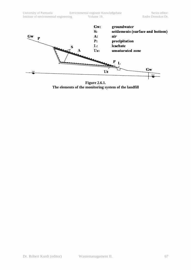
University of Pannonia Environmental engineer Knowledgebase Series editor: Institute of environmental engineering Volume 19. Endre Domokos Dr.
Figure 2.6.1.
The elements of the monitoring system of the landfill
Dr. Róbert Kurdi (editor) Wastemanagement II. 67
University of Pannonia Environmental engineer Knowledgebase Series editor: Institute of environmental engineering Volume 19. Endre Domokos Dr.
6. Designing, development and sustainable maintainance of regional waste management systems (Buruzs Adrienn)
6.1. Regulations and requirements The European Union's approach to waste management is based on three principles: Waste prevention: This is a key factor in any waste management strategy. If we can reduce the amount of waste generated in the first place and reduce its hazardousness by reducing the presence of dangerous substances in products, then disposing of it will automatically become simpler. Waste prevention is closely linked with improving manufacturing methods and influencing consumers to demand greener products and less packaging. Recycling and reuse: If waste cannot be prevented, as many of the materials as possible should be recovered, preferably by recycling. The European Commission has defined several specific 'waste streams' for priority attention, the aim being to reduce their overall environmental impact. This includes packaging waste, end-of-life vehicles, batteries, electrical and electronic waste. EU directives now require Member States to introduce legislation on waste collection, reuse, recycling and disposal of these waste streams. Several EU countries are already managing to recycle over 50% of packaging waste. Improving final disposal and monitoring: Where possible, waste that cannot be recycled or reused should be safely incinerated, with landfill only used as a last resort. Both these methods need close monitoring because of their potential for causing severe environmental damage. Waste managemet in Hungary is primarily controlled through legal regulations. Legal provisions determine technical requirements for waste management, the applicable economic incentives and sanctions, the responsibilities of the waste generator and managers of waste, as well as the licensing and supervisory duties of the authorities. In addtition to legal provisions, separate programs and funds are available for educational programs, for raising public awareness, for research, and for individual voluntary undertakings (certification, eco-labelling and eco-management systems) that help and guarantee investments for the development of waste management. Moreover, there are possibilities for publishing professional implementation guides for facilitating the treatment of various waste types. The economical management of natural resources – requiring reduction of the exploitation of non-renewable resources, efficient and economical use of material and energy resources, and extertion of minimal impacts on the environment – is an essential condition of long term sustainable development. The principles and goals of Hungarian Environmental Policy supporting sustainable development as set down in Act LIII. of 1995 on general environmental regulations are defined in relation to waste in Act VLIII. of 2000 on waste management. The framework legislation has been established in conformity with the EU Directive 2006/12/EC on waste. The mid-term waste management strategy of Hungary is defined in National Waste Management Plans (NWMP) prepared for six-year periods, of which the first planning period 2003-2008 has been expired. The new NWMP-II for 2009-2014 was elaborated in parallel to the upgrading of the Waste Management Act in order to harmonize national legislation, targets and implementation tools to the new EU Waste Framework Directive 2008/98/EC. Aims, tasks and priorities of medium term development plans of national waste management are defined in the National
Dr. Róbert Kurdi (editor) Wastemanagement II. 68
University of Pannonia Environmental engineer Knowledgebase Series editor: Institute of environmental engineering Volume 19. Endre Domokos Dr.
Waste Management Plan II, which was made for the period of 2009–2014 in Hungary. The most important areas are related to the developing projects of municipal solid waste treatment (increasing the capacity of landfills, accomplishment of the infrastructure of selective waste collection, building of new composting plants). According to the Plan, Hungary will be deposition-orientated until 2015. The main problems to the next years will be the lack of reprocessing industry of plastic and glass packaging waste. The high number of to-be-recultivated landfills and the attainability of necessary financial sources are also serious problems. The principles that underpin the Hungarian waste management strategy are:
• Sustainability – meeting the needs of the present without compromising the ability of future generations to meet their own needs.
• Self-sufficiency and the proximity principle – waste should be managed and disposed of as close as practicable to where it is generated.
• The waste hierarchy – to move as close as possible to the top of the hierarchy by minimising the waste generated, reusing waste materials, recycling, and, where this is not possible, disposing of waste in ways that unlock or recover energy, for example in energy from waste plants.
• Best Practicable Environmental Option – a method of option appraisal used to examine the best way of dealing with various types of waste in the light of social, environmental, economic, practicality and other policy issues.
In order to ensure the sustainable use of natural resources it supports the use of technologies generating minimum amount of waste with economical material and energy consumption, thereby preventing the pile-up of waste; utilisation of materials producing less hazardous waste, representing lower risk; as well as recovery to the fullest the generated waste materials and energy; and finally disposal of non-reusable waste in an environmentally friendly manner, that does not cause hazards to human health, and as a part of this, reduction to the mimimum of waste disposal in areas where this would have a long term impact on the environment, especially in valuable areas. Economic growth over the last century has been matched by increases in the amount of solid wastes that society produces. Current predictions indicate a doubling of the generation of certain wastes by 2025, while municipal waste in the EU is projected to increase 25% by 2020. The precise figure varies by country, however, with the generation of municipal waste projected to grow faster in the newer member states. In addition, there is a clear correlation between the concentration of populations and generation of municipal waste. Among the EU-15 member states, for instance, the five most populous countries – Germany, the United Kingdom, France, Italy, and Spain – generate 80% of the total municipal waste. The same holds true for the 10 newer member states, where Poland and Hungary produce about 65% of the total waste.
6.2. Concrete actions taken and specific progress made in implementation
The main measures to be taken have been defined in the NWMPs. Major tasks to be solved or managed by the implementation of NWMP are as follows:
• reduce both the high absolute value of waste generation and the high proportion of waste generated, as compared to the production value;
Dr. Róbert Kurdi (editor) Wastemanagement II. 69

University of Pannonia Environmental engineer Knowledgebase Series editor: Institute of environmental engineering Volume 19. Endre Domokos Dr.
• increase the ratio of recovery which is low for most waste types, encourage economical material and energy recovery;
• minimize the currently high proportion of waste disposal by landfill; • gradually eliminate the sources of hazard and the contaminated sites which resulted
from the unsuitable waste disposal of the past decades; • promote – through market-conform economic instruments – the solutions that are
beneficial in the long term, in accordance with the principles of sustainable development, and the construction of modern, complex waste management systems, having special regard to recovery;
• promote research and technical development in line with achieving the goals of waste management;
• strengthen the co-operation between the state and the private sector, to support the local or local community initiatives, having special regard to selective waste collection and recovery;
• increase the efficiency of education, training and awareness raising activities.
Table 1. Annual waste production and the GDP in Hungary 2000 2004 2005 2006 2007 2008* Total waste production, 1000 tons/year 40 700 30 045 28 558 26 607 25 858 25 000 Total waste production, % of the previous year
90.4 93.9 95.1 93.2 97.2 96.7
GDP, % of the previous year 105.2 104.8 104.1 103.9 101.3 100.08
Source: Ministry of Environment and Water; * Estimated value Through legislative, economic and public relation measures, progress made in a number of areas: • The annual amount of waste decreased by 38% (from some 41 million tons to 26 million
tons) from 2000 to 2007, but municipal solid waste generation changed from 4.55 million tons to 4.59 million tons. In the same time period the GDP increased by about 35%.
Table 2. Generation of municipal solid waste (MSW) and the GDP 2000 2001 2002 2003 2004 2005 2006 2007 2008* Generation of MSW , 1000 tons/year
4 552 4 603 4 646 4 693 4 591 4 646 4 711 4 594 4 400
Generation of MSW, % of the previous year
101.1 101.1 100.9 101.0 97.8 101.2 101.4 97.5 95.8
Real income, % of the previous year
101.5 106.4 113.6 109.2 98.9 106.3 103.5 96.0 n.a.
Source: Hungarian Central Statistical Office, Ministry of Environment and Water; * Estimated value • The recovery rate of total generated waste decreased from 27% to 25% but on municipal
waste this rate increased from 3% to 20% between 2000 and 2007. • The rate of disposal by landfills decreased from 52% to 45% between 2000 and 2007 but
municipal waste landfill rate changed from 85% to 75%.
Dr. Róbert Kurdi (editor) Wastemanagement II. 70

University of Pannonia Environmental engineer Knowledgebase Series editor: Institute of environmental engineering Volume 19. Endre Domokos Dr.
Table 3. Waste treatment in Hungary (without waste water sludge) 2004 2005 2006 2007
tons % tons % tons % tons %
Recycling 8 892 837 29.8 7 630 197 26.9 6 697 451 25.2 4 629 467 18.4
Energy recovery
911 322 3.1 1 271 472 4.5 1 627 237 6.1 1 354 938 5.4
Incineration 169 852 0.6 52 756 0.2 101 434 0.4 77 935 0.3
Landfill 17 415 456 58.3 13 602 494 48.0 14 288 930 53.7 11 325 094 45.0
Other 2 461 033 8.2 5 799 114 20.4 3 892 287 14.6 7 758 88 30.9
Source: database of the Waste Information System (HIR)
Table 4. Treatment of municipal solid waste (1000 tons) 2000 2001 2002 2003 2004 2005 2006 2007 Recycling 350 360 400 490 540 444 490 554 Energy recovery 340 350 280 240 155 303 389 389 Landfill 3,760 3,800 3,890 3,900 3,857 3,859 3,792 3,428 Other n.a n.a n.a n.a 40 40 40 229
Source: Hungarian Central Statistical Office, Ministry of Environment and Water * The fluctuation of the values of ’energy recovery’ is caused by the stopping the operation of the Waste Recovery Plant of Budapest and restarting it due to reconstruction. • In accordance with the EU regulations, Hungary introduced the extended producer
responsibility for certain products (waste electrical and electronic equipment – WEEE, packaging, end of life vehicles – ELV, batteries), and fulfilled the EU obligations on the reduction of heavy metal contents of the goods available on the market, and waste collection and recovery targets.
• To promote the collection and recycling of certain products’ waste a special product fee is used (on packaging, electronics, accumulators, tyres, oil-products, advertising papers, cooling agents); producers pay reduced product fee if they collect and recover the waste of their products. Steps were also taken to promote the use of reusable packaging and regulations encouraged the bottle deposit scheme.
• Special subsidizing systems were elaborated for companies o to introduce and develop low-waste and recovery technologies, and for marketing
environmental-friendly, and/or recycled products, o to help R+D+I of such kind of technologies and products, o to develop complex regional municipal solid waste management systems, including
the investments in reuse centers, home-composting, selective collection systems, composting and up-to-date landfill sites.
• The base of these supporting programs is the National Development Plan; the sources are covered by different EU funds and the self-contribution of the investor.
The amount of collected municipal waste increased slightly between 2000 and 2007. The reason was the unfavorable change in consumer preferences and the development of public services in the field of municipal solid waste collection and management. No real link between GDP and municipal waste generation observed but there is a strong link between real wages and the level of consumption.
Dr. Róbert Kurdi (editor) Wastemanagement II. 71

University of Pannonia Environmental engineer Knowledgebase Series editor: Institute of environmental engineering Volume 19. Endre Domokos Dr.
6.3. Recent trends and emerging issues In the recent global economic market and fiscal system the natural trends show that increasing consumption generates more household waste, but economic trends and efficiency motivations push the production sector generating less waste. Increasing of recovery depends mainly on demand of raw materials and on consumption patterns. In Hungary the main tasks in the next couple of years would be:
• elaboration of an effective national waste prevention program, • raising demand on secondary raw materials and recycled products, • increasing the recovery of construction/demolition waste, • increasing the use of waste as fuel, replacing non-renewable energy sources, • minimization of landfill in general and those of biodegradable waste in particular.
6.3.1. Waste management in hungary In Hungary about 4.7 million tons municipal solid waste (MSW) generates per year and 85% of this quantity gets to landfills. The ratio of disposal has to reduce to 50% by 2013. Theoretically there are three ways to carry out the obligations:
• prevention of waste, • recycling waste as material and • the thermic recovering.
Waste management policy has to concentrate on changing economic and fiscal interests, and at the same time on changing consumption patterns. For this sake strengthened legislation is needed with quantitative targets, enforcement and wider use of producers’ responsibility and more effective economic incentives. Trends can be changed or turned only if external environmental costs are built into prices of primary goods, making more expensive the use of them, and raising demand on secondary goods. At the same time subsidies are continuously needed for the development and marketing of durable and reusable, easily recyclable products, and for low-waste or non-waste technologies and for recycling industry. Changing public and private procurement patterns is also needed to encourage the use of secondary raw materials and recycled products The national environmental policy does not focus traditionally on the prevention of waste production. NWMP simply prognosticates the increasing of municipal solid waste from 4.7 million tons to 5.2 million tons in this decade. There are two alternatives to prevent the generating of waste. The first is the application of clean technologies (low waste technologies). Either waste is not generated in this alternative or the volume of waste is low. The second alternative is the producing of recyclable articles. It means articles stay in producing-consuming process for a long time. According to the 1999/31/EK directive on waste deposition the quantity of deposited biodegradable organic waste has to be decreased by 35%, 50% and 65% by the year 2006, 2009 and 2016 compared to the level of deposited organic waste in 1995. The capacity of projects
Dr. Róbert Kurdi (editor) Wastemanagement II. 72

University of Pannonia Environmental engineer Knowledgebase Series editor: Institute of environmental engineering Volume 19. Endre Domokos Dr.
which were realized in 2009 and 2010 are not enough for the 50% recycling therefore newer capacities are needed to be built up using the financial sources of the European Union. There are several ways to recycle the biodegradable organic waste:
• selective collection and composting of bio waste (households waste) and green waste; • production of biogas; • selective collection and recycling of paper; • thermic treatment and energetic recovery (e.g. pyrolysis, incineration).
Compost preparation of bio and green waste realizes in many composting plants and in households. The composting capacity was 200 thousand tons in 2004 and 11% of the generated compostable waste was recycled. Thanks to the increasing capacity that percentage increased more than 20% by 2009. The collection and composting of green waste (20-40 kg/person/year) which is generated in suburbs, public parks and other green spaces are coming along well. On the contrary, collection of bio waste (70-90 kg/person/year) generating in cities and housing estates is in initial stage. In Hungary 3.8 toe biogas is generated every year and from this 25 GWh electricity is produced. Considering the above mentioned quantities, Hungary is one of the last countries in Europe in despite of our potential possibilities. The quantity of agricultural biomass is 8-10 million tons per year and producible electricity is 7-9 PJ. Unfortunately only few biogas plants have considerable capacity in Hungary. Biogas exploiting wells work in 14 waste dumpsites but that biogas can mostly operate low capacity gas engines. The exploited biogas is 100-120 million m3 and the produced electricity which derives from MSW is 7.6 GWh.
Figure 1. Proportion of incineration recycling and landfilling of MSW
The thermic treatment of MSW is realized in the Waste Incineration Plant of Budapest, which is the only one municipal waste incineration plant in Hungary. Electricity is produced from the forming heat of incinerated waste. Between 2002 and 2005 the complete reconstruction of the plant took place and from 2006 it has operated with total capacity which is 420 thousand tons per year. Recently not entirely 4% of all the quantity of MSW is recovered in thermic way (Figure 1). According to the developing strategy of MSW management that percentage will increase above 8%. The high expenses of investment and operation and the new directives of
Dr. Róbert Kurdi (editor) Wastemanagement II. 73

University of Pannonia Environmental engineer Knowledgebase Series editor: Institute of environmental engineering Volume 19. Endre Domokos Dr.
the EU on packaging waste, which prefer the material recycling to energetic recovery make the execution doubtful and questions its reasonableness. In Hungary the deposition of waste is the determining treatment manner and it is likely to stay in the future. In January 2003 a PHARE supported survey was finished which mapped 2667 dumping sites of MSW countrywide and 665 of them had operational permit. Approximately 1900-2000 dumpsites operated illegally. 60-65% of the illegal landfills were official closed by local governments. The economic considerations were primary in the process when local governments selected the places of dumpsites. The authorities preferred economically valueless and destructed places. Most of the landfills were built too close to settlements and 45% of them were located in former open pits. The environmental considerations were secondary in siting. The waste tips environmental properties were remarkably unfavourable in two-thirds of the sites and those sites were in pollution sensitive areas. Due to unfavourable properties the numbers of operating landfills with operational permit decrease in the last few years (Figure 2).
Figure 2. The operating landfills between 2005 and 2009 and after 2009
Huge waste management projects were in progress in the last years, many forming part of a waste management mega-project of Ft 57.4 billion announced in November 2005 and begun in 2006. The program is designed to establish EU-compliant waste management in extant nationwide garbage disposal sites by introducing a selective waste collection strategy and
optimizing logistics systems. Only 57 dumpsites of former landfills operate after 2009. One of the most serious challenges of national waste management to recultivate closed and unpermitted landfills due to high financial and technological requirements. The regional projects significantly contribute to the fulfillment of the aims of waste management. Due to the building-up of selective collection systems and treatment plants of biodegradable organic waste, the quantity of material recovered waste will increase, hereby the quantity of deposited waste will decrease. The developing and increasing of capacities from 2009 were needed first of all in Western Transdanubia Region, Central Transdanubia Region and Central Hungary Region. The developing and increasing included the building of new dumping sites and increasing the
Dr. Róbert Kurdi (editor) Wastemanagement II. 74
University of Pannonia Environmental engineer Knowledgebase Series editor: Institute of environmental engineering Volume 19. Endre Domokos Dr.
capacity of existed waste tips. Utilization-orientated waste management zones and reprocessing industry were needed to be organized.
6.3.2. Municipal solid waste generation Waste is one of the the most visible environmental problems. Increasing population, changing consumption patterns, economic development, changing income, urbanization and industrialization result in increased generation of solid waste and also a diversification of the types of the solid waste generated. Increased waste generation creates more environmental problems in the country. The consequence is environmental degradation, caused by inadequate disposal of waste. The impact of disposed waste is composed of:
• the contamination of surface and groundwater through leachate; • soil contamination through direct waste contact or leachate; • air pollution through burning of wastes; • spreading of diseases by different vectors like birds, insects, and rodents; • odor in landfills, and • uncontrolled release of methane by anaerobic decomposition of waste.
Waste includes all items that people or companies no longer have any use for, which they either intend to get rid of or have already discarded. However, waste can also be a resource if it is put in the right place. Many items can be considered as waste, for instance household rubbish, sewage sludge, wastes from manufacturing activities, packaging items, discarded cars, discarded electronic devices, garden waste, old paint containers, etc. Thus all our daily activities can give rise to a large variety of different wastes arising from different sources. Waste cannot responsibly be dumped without due concern and preparation, because not only is it unsightly, unhygienic, and potentially disastrous to our environment, it also requires the allocation of space and incurs costs related to the consequences of the waste disposal. Moreover, suitable landfill sites are becoming more difficult to find as urban areas expand. Also, individuals are not willing to accept the implementation of a new landfill site near them because of concerns about smell, litter, pollution, pests and the reduction in the value of their homes. There are large costs involved in providing conveniently located and environmentally responsible landfill facilities. In recent years, the notion of integrated waste management, applied to reduce waste at its source before it even enters the waste stream, has spread. It means that waste materials generated must be recovered for reuse and recycling, and the rest should be disposed at landfill sites. Unfortunately, disposal is not a sustainable solid waste management solution. Also, the zero emissions concept has arisen since the late 1990s. The concept is reflected by the phrase ‘no time for waste’ because the concept envisages all industrial outputs from processing being used as input process materials or converted into value added inputs for other processes, maximizing resource consumption and increasing eco-efficiency. In this way, the production process is reorganized into a closed loop system which emulates as an industrial metabolism of the sustainable cycles found in nature ‘grown–use–waste–reuse’. Also, waste can be fully matched with the input requirements of any other processes. A perfectly integrated process management produces ‘no waste’ and it can be an innovative system of sustainable industry development, where reduction, minimization, and utilization of waste are simultaneously realized. Solid waste also includes wastes generated from residential, commercial, industrial, or institutional construction, as well as from demolition processes and municipal services. However, this definition varies greatly among waste studies, and some sources are commonly
Dr. Róbert Kurdi (editor) Wastemanagement II. 75

University of Pannonia Environmental engineer Knowledgebase Series editor: Institute of environmental engineering Volume 19. Endre Domokos Dr.
excluded, such as industrial, construction and demolition, and also commercial and municipal services.
6.4. Practical implementation of waste management Waste management is an umbrella term that refers to a host of interlinked activities such as collection, transportation, processing, recycling, disposal, reduction and monitoring of waste materials. Waste management plants and equipment comprise various devices and machines used for treating, converting, disposing and processing wastes from various sources. Waste management plants and equipment can be classified on the basis of the type of waste to be disposed like organic, inorganic, biodegradable, etc or on the basis of source of waste like electronic waste, medical waste etc. Further, the management of wastes can include processing solid, liquid, gaseous or radioactive substances, with different methods and equipment needed for each. Managing wastes has assumed greater importance today amidst growing concerns for the environment and an increasing number of businesses are taking up the responsibility for treating and managing the waste they generate. Treatment of waste – and the collection of waste appropriate for treatment, recovery and disposal – is basically the responsibility of the waste generator, or its owner. This responsibility is met by adhering to conditions, set in legal provisions, in accordance with the ‚polluter pays‘ principle by carrying out the treatment, which is an activity requiring a license, or handing over the waste to an organisation, licensed to carry out treatment and paying the cost of the treatment. In case of municipal waste, the municipal governments are responsible for organising municipal sevices, ensuring the treatment of municipal waste, so that the responsibility of the inhabitants can be enforced. Organisations gathering, recovering and disposing waste are eligible to start and carry on their activity only upon licence, granted by environmental authorities. They have to keep records of their activity, of the quantity and quality of waste they treat, and have to report annually to authorities. Prevention of waste generation and of its hazardous nature can be characterized by decrease in amount of waste. This decrease – especially towards the early 90’s – resulted from economic recession, rather than from conscious prevention measures. In case of industrial waste, the continual structural changes of the industry and the accompanying product and technology developments result simultaneously in a decreased quantity of waste and less hazardous waste. The quantity of municipal solid waste has significantly not changed, despite of the continuous increase in consumption. This can be explained on the one hand by the supplanting of solid heating material use, and on the other hand by the increasing amount of light fractions, as paper and cardboard. A fairly low proportion of the generated waste is recovered in comparison to international practice. Less than 30 % of industrial non-hazardous waste and less than 20 % of hazardous waste is recovered. Only 3 % of municipal waste- gathered within the framework of public services – are recovered. Thus, the total of waste recovery – not including the recovery of agricultural plant residues – amounts to less than 30 %. This result was reached only as a consequence of introducing the product charge system, which resulted in recovery of some 35 % of packaging materials, some 95 % of used accumulators (although these are processed abroad), and 40 % of waste oil.
Dr. Róbert Kurdi (editor) Wastemanagement II. 76

University of Pannonia Environmental engineer Knowledgebase Series editor: Institute of environmental engineering Volume 19. Endre Domokos Dr.
The typical treatment of generated waste is disposal, and as a part of this, the landfill. The ratio of the latter – not considering agricultural waste – is over 50 %.
6.5. Waste sources and composition Waste composition is influenced by external factors, such as geographical location, the population’s standard of living, energy source, and weather. The most fundamental step in waste source management is quantifying and qualifying the different types of waste being generated. It is important to have a system for the collection, segregation, and analysis of basic information about wastes, for example, the sources of wastes, the quantities of waste generated, their composition and characteristics, the seasonal variations and future trends of generation. This is the best way to identify the method to treat waste, since municipal, industrial, agricultural, hazardous and toxic wastes, as well as wastewater, require different treatment methods.
6.6. Municipal solid waste Municipal solid waste (MSW) is generated by households, commercial activities and other sources whose activities are similar to those of households and commercial enterprises, for example, wastes from offices, hotels, supermarkets, shops, schools, institutions, and from municipal services such as street cleaning and maintenance of recreational areas. It does not include other wastes, such as those arising from mining, industrial production or construction and demolition processes. The major types of MSW are food wastes, paper, plastic, rags, metal and glass, with some hazardous household wastes such as electric light bulbs, batteries, discarded medicines and automotive parts.
6.7. regional waste management systems Urban and rural municipalities can join together to form a regional waste management system and delegate their waste management responsibilities to a central authority. The authority is a separate legal entity, governed by a board, with representatives from the communities and rural municipalities. Features of regional waste management system:
• closure of most municipal landfills within the region, with only one or two centralized landfills (depending on region size) used by all municipalities belonging to the regional system;
• operation of transfer stations (temporary waste storage sites) replacing some of the landfills;
• consolidated waste collection; • operation of recycling programs for the entire region; and • joint public education programs.
Dr. Róbert Kurdi (editor) Wastemanagement II. 77
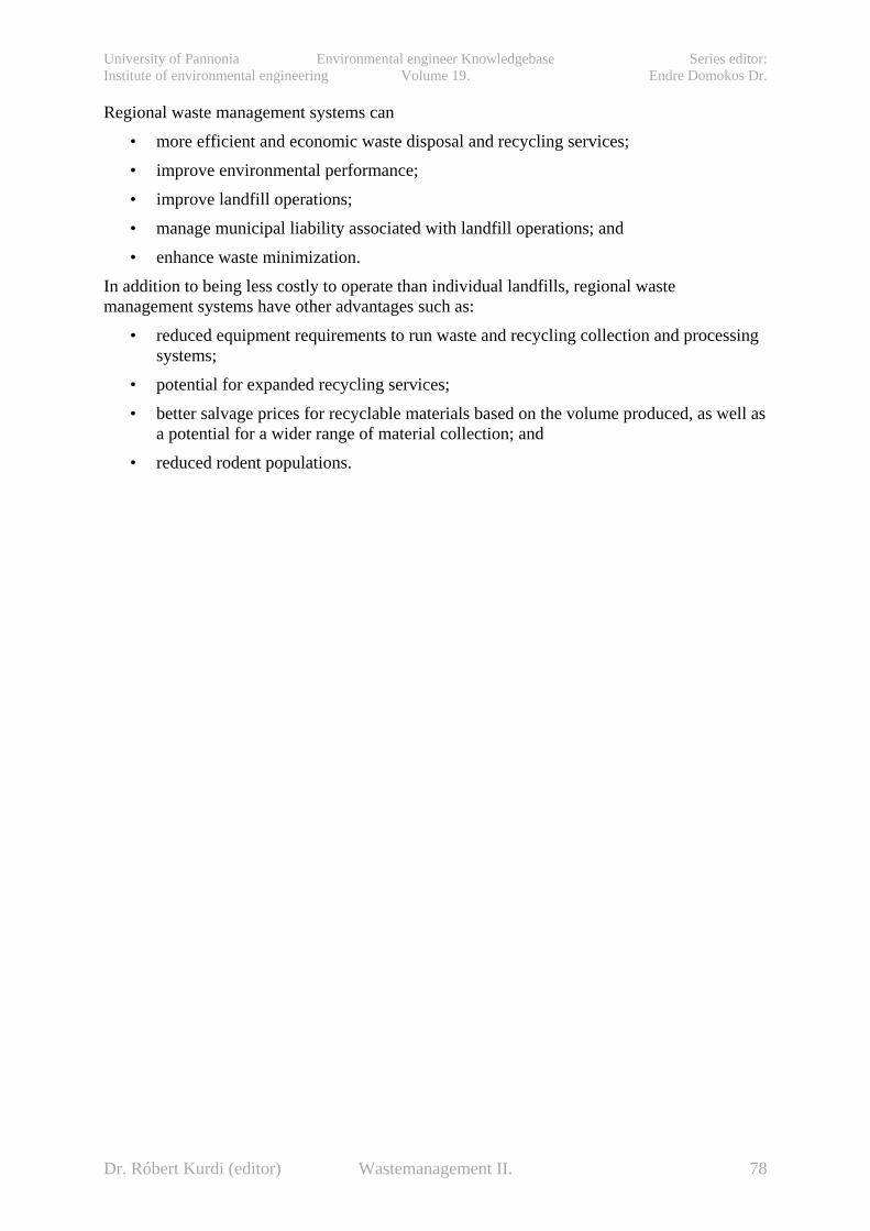
University of Pannonia Environmental engineer Knowledgebase Series editor: Institute of environmental engineering Volume 19. Endre Domokos Dr.
Regional waste management systems can • more efficient and economic waste disposal and recycling services; • improve environmental performance; • improve landfill operations; • manage municipal liability associated with landfill operations; and • enhance waste minimization.
In addition to being less costly to operate than individual landfills, regional waste management systems have other advantages such as:
• reduced equipment requirements to run waste and recycling collection and processing systems;
• potential for expanded recycling services; • better salvage prices for recyclable materials based on the volume produced, as well as
a potential for a wider range of material collection; and • reduced rodent populations.
Dr. Róbert Kurdi (editor) Wastemanagement II. 78

University of Pannonia Environmental engineer Knowledgebase Series editor: Institute of environmental engineering Volume 19. Endre Domokos Dr.
7. The keys to a successful regional waste management system Participation of Rural Municipalities All future users should share the cost of building the basic infrastructure. Everyone, rural and urban, will use the system once it is in place.
Public Information The more open the process, the more likely that the public will support it. Keeping everyone informed is a constant and crucial part of a successful regional system.
Stick to Time Lines When implementing a regional waste management system, make sure that everyone in the region receives the service within a reasonable and clearly defined time frame. This will avoid claims of inequity and build faith in the system.
Fair Representation of Urban and Rural Representatives Involved communities need to feel that they can have a voice in how the system is run. It is also important to balance urban and rural interests on the regional authority board.
The Need for Champions Most new projects require committed local citizens to champion the cause. These people lead the process and keep it going when setbacks occur.
7.1. Integrated approach for sustainable solid waste management Sustainable waste management must go beyond the mere safe disposal or recovery of wastes that are generated and must seek to address the root cause of the problem by attempting to change unsustainable patterns of production and consumption. Additionally, it should be realized by using the technical, organizational and financial resources available in a particular locality, followed by waste policy (waste hierarchy), waste planning, regulatory framework, and enforcement of the law. The quantity of solid waste generation is mostly associated with the economic status of a society. Generation of solid waste is a natural consequence of human life. Removal of that waste is consistent with improved quality of life. Initially, solid waste management techniques aimed simply to eliminate waste from the vicinity of habitable areas as a means of maintaining public health (Figure 3). After realizing the hazards of uncontrolled disposal, measures were devised and implemented mainly through sanitary landfilling. In recent years, a variety of material and energy recovery technologies have been devised and are now included in modern systems. Global efforts are now in force to reorient solid waste management systems toward sustainability.
Dr. Róbert Kurdi (editor) Wastemanagement II. 79
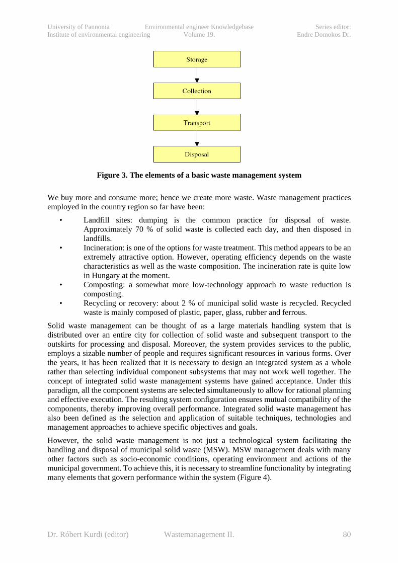
University of Pannonia Environmental engineer Knowledgebase Series editor: Institute of environmental engineering Volume 19. Endre Domokos Dr.
Figure 3. The elements of a basic waste management system
We buy more and consume more; hence we create more waste. Waste management practices employed in the country region so far have been:
• Landfill sites: dumping is the common practice for disposal of waste. Approximately 70 % of solid waste is collected each day, and then disposed in landfills.
• Incineration: is one of the options for waste treatment. This method appears to be an extremely attractive option. However, operating efficiency depends on the waste characteristics as well as the waste composition. The incineration rate is quite low in Hungary at the moment.
• Composting: a somewhat more low-technology approach to waste reduction is composting.
• Recycling or recovery: about 2 % of municipal solid waste is recycled. Recycled waste is mainly composed of plastic, paper, glass, rubber and ferrous.
Solid waste management can be thought of as a large materials handling system that is distributed over an entire city for collection of solid waste and subsequent transport to the outskirts for processing and disposal. Moreover, the system provides services to the public, employs a sizable number of people and requires significant resources in various forms. Over the years, it has been realized that it is necessary to design an integrated system as a whole rather than selecting individual component subsystems that may not work well together. The concept of integrated solid waste management systems have gained acceptance. Under this paradigm, all the component systems are selected simultaneously to allow for rational planning and effective execution. The resulting system configuration ensures mutual compatibility of the components, thereby improving overall performance. Integrated solid waste management has also been defined as the selection and application of suitable techniques, technologies and management approaches to achieve specific objectives and goals. However, the solid waste management is not just a technological system facilitating the handling and disposal of municipal solid waste (MSW). MSW management deals with many other factors such as socio-economic conditions, operating environment and actions of the municipal government. To achieve this, it is necessary to streamline functionality by integrating many elements that govern performance within the system (Figure 4).
Dr. Róbert Kurdi (editor) Wastemanagement II. 80
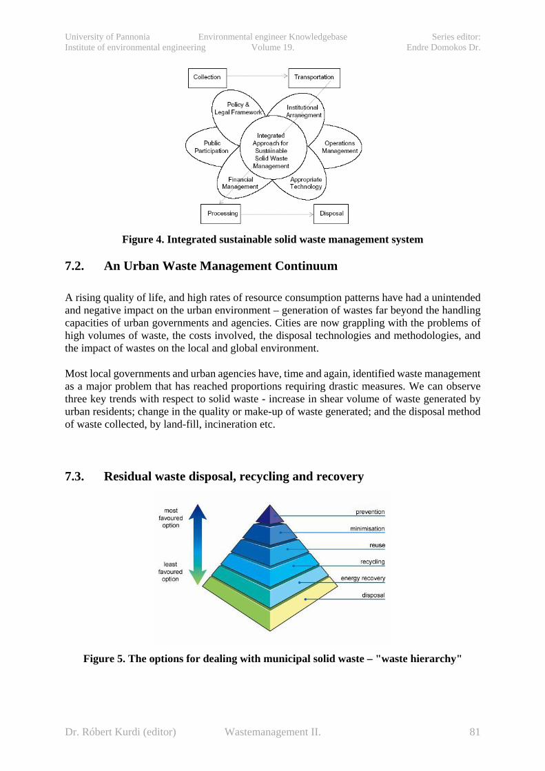
University of Pannonia Environmental engineer Knowledgebase Series editor: Institute of environmental engineering Volume 19. Endre Domokos Dr.
Figure 4. Integrated sustainable solid waste management system
7.2. An Urban Waste Management Continuum A rising quality of life, and high rates of resource consumption patterns have had a unintended and negative impact on the urban environment – generation of wastes far beyond the handling capacities of urban governments and agencies. Cities are now grappling with the problems of high volumes of waste, the costs involved, the disposal technologies and methodologies, and the impact of wastes on the local and global environment.
Most local governments and urban agencies have, time and again, identified waste management as a major problem that has reached proportions requiring drastic measures. We can observe three key trends with respect to solid waste - increase in shear volume of waste generated by urban residents; change in the quality or make-up of waste generated; and the disposal method of waste collected, by land-fill, incineration etc.
7.3. Residual waste disposal, recycling and recovery
Figure 5. The options for dealing with municipal solid waste – "waste hierarchy"
Dr. Róbert Kurdi (editor) Wastemanagement II. 81

University of Pannonia Environmental engineer Knowledgebase Series editor: Institute of environmental engineering Volume 19. Endre Domokos Dr.
After collection, the residual waste is disposed of (either through landfill or incineration) and the recyclate remanufactured and/or energy recovered (if energy is recovered from waste it is classed as recovery rather than disposal - see incineration below). The options for dealing with municipal solid waste are described in the "waste hierarchy" (Figure 5) – with those towards the top of the list more desirable than those towards the bottom. The main methods currently employed are landfilling, recycling, composting and energy from waste plants. These together with alternative and emerging technologies are discussed below. Despite the hierarchy, the majority of Hungary’s waste is still being disposed of through landfill. Whilst it is difficult to monitor reduction and reuse schemes, municipalities, authorities and waste management companies do collect figures allowing to note how much of collected waste is intended for recycling (or recovery) and how much for final disposal through landfill.
7.4. waste treatment technologies 7.4.1. A mechanical biological treatment system Table 5. Strengths and Weaknesses of MBT
Strengths Weaknesses
Reduces the mass of the input waste through stabilisation/composting processes (by ~20%)
Landfill of residue will still count as Biodegradable Municipal Waste (BMW) with regard to the Landfill Directive unless further treated. It would also pay the full Landfill Tax.
Designed to extract additional recyclate from the residual waste stream
The system is reliant on other treatment / disposal processes for the residues
Based on combinations of existing proven technologies
No plant currently in operation in the UK (although some plant due for commissioning over the next two years)
Homogenises residual waste feedstock for use as fuel in other processes (e.g. cement kilns, power stations, other waste recovery processes)
Lower value for recyclate derived from a mixed residual stream
Increases calorific value of waste through drying / separation
Potential contamination issues over products from composting or Anaerobic Digestion of waste limiting potential applications
Is designed to be part of an integrated system
Residue is likely to be subject to Animal By-Products Regulation requirements for any additional composting.
A mechanical biological treatment system is a form of waste processing facility that combines a sorting facility with a form of biological treatment such as composting or anaerobic digestion. MBT plants are designed to process mixed household waste as well as commercial and industrial wastes (Figure 6-10., Table 5).
Dr. Róbert Kurdi (editor) Wastemanagement II. 82

University of Pannonia Environmental engineer Knowledgebase Series editor: Institute of environmental engineering Volume 19. Endre Domokos Dr.
Figure 6. Process flow chart of MBT
Figure 7. Covered MSW with semipermeable film
Figure 8: Waste after MBT treatment
Dr. Róbert Kurdi (editor) Wastemanagement II. 83
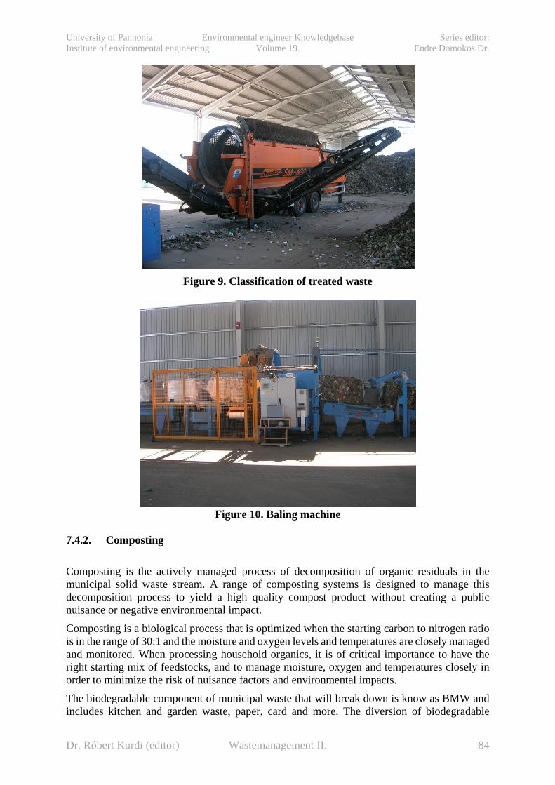
University of Pannonia Environmental engineer Knowledgebase Series editor: Institute of environmental engineering Volume 19. Endre Domokos Dr.
Figure 9. Classification of treated waste
Figure 10. Baling machine
7.4.2. Composting Composting is the actively managed process of decomposition of organic residuals in the municipal solid waste stream. A range of composting systems is designed to manage this decomposition process to yield a high quality compost product without creating a public nuisance or negative environmental impact. Composting is a biological process that is optimized when the starting carbon to nitrogen ratio is in the range of 30:1 and the moisture and oxygen levels and temperatures are closely managed and monitored. When processing household organics, it is of critical importance to have the right starting mix of feedstocks, and to manage moisture, oxygen and temperatures closely in order to minimize the risk of nuisance factors and environmental impacts. The biodegradable component of municipal waste that will break down is know as BMW and includes kitchen and garden waste, paper, card and more. The diversion of biodegradable
Dr. Róbert Kurdi (editor) Wastemanagement II. 84
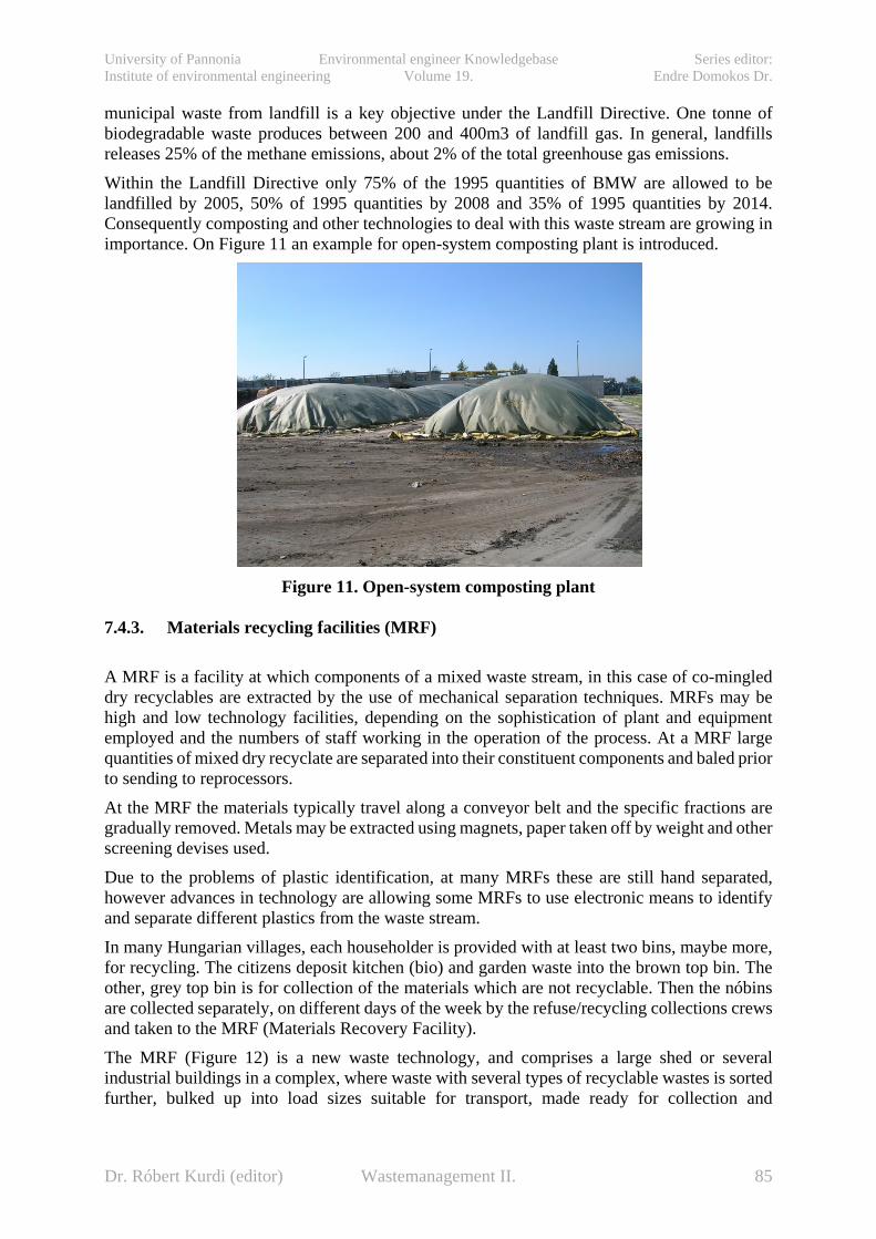
University of Pannonia Environmental engineer Knowledgebase Series editor: Institute of environmental engineering Volume 19. Endre Domokos Dr.
municipal waste from landfill is a key objective under the Landfill Directive. One tonne of biodegradable waste produces between 200 and 400m3 of landfill gas. In general, landfills releases 25% of the methane emissions, about 2% of the total greenhouse gas emissions. Within the Landfill Directive only 75% of the 1995 quantities of BMW are allowed to be landfilled by 2005, 50% of 1995 quantities by 2008 and 35% of 1995 quantities by 2014. Consequently composting and other technologies to deal with this waste stream are growing in importance. On Figure 11 an example for open-system composting plant is introduced.
Figure 11. Open-system composting plant
7.4.3. Materials recycling facilities (MRF) A MRF is a facility at which components of a mixed waste stream, in this case of co-mingled dry recyclables are extracted by the use of mechanical separation techniques. MRFs may be high and low technology facilities, depending on the sophistication of plant and equipment employed and the numbers of staff working in the operation of the process. At a MRF large quantities of mixed dry recyclate are separated into their constituent components and baled prior to sending to reprocessors. At the MRF the materials typically travel along a conveyor belt and the specific fractions are gradually removed. Metals may be extracted using magnets, paper taken off by weight and other screening devises used. Due to the problems of plastic identification, at many MRFs these are still hand separated, however advances in technology are allowing some MRFs to use electronic means to identify and separate different plastics from the waste stream. In many Hungarian villages, each householder is provided with at least two bins, maybe more, for recycling. The citizens deposit kitchen (bio) and garden waste into the brown top bin. The other, grey top bin is for collection of the materials which are not recyclable. Then the nóbins are collected separately, on different days of the week by the refuse/recycling collections crews and taken to the MRF (Materials Recovery Facility). The MRF (Figure 12) is a new waste technology, and comprises a large shed or several industrial buildings in a complex, where waste with several types of recyclable wastes is sorted further, bulked up into load sizes suitable for transport, made ready for collection and
Dr. Róbert Kurdi (editor) Wastemanagement II. 85

University of Pannonia Environmental engineer Knowledgebase Series editor: Institute of environmental engineering Volume 19. Endre Domokos Dr.
transportation, sold, stored, and shipped to the buyers including some of the original manufacturers.
Figure 12. Domestic waste sorting machine
7.4.4. Incineration Incineration is the burning of waste. Incineration may be carried out with or without energy recovery. With energy recovery, it forms the third of the three recovery processes in the waste hierarchy. Without energy recovery it is a form of disposal, like landfill (see above). Energy can be recovered from waste either by direct waste incineration (typically mass burn incineration plants, taking unsorted waste) or by using waste as a fuel substitute (either directly or as a "refuse derived fuel"). The technology to burn waste has developed significantly over the past 50 years and incinerators are now much cleaner than they used to be. The energy released from burning the rubbish is often used to generate electricity. Even greater benefits can be gained by using the extra heat to heat nearby housing or offices. However, despite improvements in the operation of incinerators, there is strong public concern about health effects. And from a resource point of view, incineration may not be the best way to deal with our rubbish. Even if energy is obtained through the process, incinerating our rubbish may be a waste of valuable resources.
7.4.5. Refuse derived fuel (RDF) Refuse derived fuel is created from fractions of the waste stream with a high energy content; typically paper, plastics, textiles and wood etc. Mixed waste is separated using screens and mechanical processes, to remove glass and metals for recycling, the biodegradable content and RDF.
Dr. Róbert Kurdi (editor) Wastemanagement II. 86

University of Pannonia Environmental engineer Knowledgebase Series editor: Institute of environmental engineering Volume 19. Endre Domokos Dr.
RDF can be used for thermal treatment or in an existing industrial process. RDF can often be used in conjunction with other fuels in a process known as co-combustion, such as exists in cement kilns where worn tyres may be used.
7.4.6. Other energy from waste processes There have recently been developments in new technologies for the disposal of waste, many of which are becoming increasingly viable options for the disposal of household waste.
7.4.7. Gasification Whilst traditionally using fossil fuels like coal, gasification has the capability to accept mixed fuels including waste. The fuel (biomass) is heated in anaerobic conditions producing a low energy gas containing hydrogen, oxygen and methane which can then be used to generate electricity. With new technology the resulting emissions give a favourable alternative to incineration.
7.4.8. Pyrolysis This is an emerging technology similar to gasification, however in this process there is total absence of oxygen. Pyrolysis is used on carbon materials and refuse derived fuel (RDF). This produces gas, oil and char. Char is produced as a by product of this process and can be recovered for use as a fuel eg gasification or alternatively disposed of. Gas and oil can be processed and then combusted and used to generate electricity. Strict legislation is imposed on these processes due to their hazardous emissions such as heavy metals. These can be reduced by the fitting of flue-gas cleaning equipment. 7.4.9. Landfill Historically, Hungary has landfilled (or "dumped") much of its waste. At the most basic level landfilling involves placing waste in a hole in the ground and covering it with soil. Today, the engineering of a modern landfill is a complex process, typically involving lining and capping individual “cells” or compartments into which waste is compacted and covered to prevent the escape of polluting liquid or gases. In newer landfill sites, systems are installed to capture and remove the gases and liquids produced by the rotting rubbish. Poorly managed sites have resulted in polluted ground or surface waters and uncontrolled landfill gas generation. Without proper control, landfills can be a source of nuisance to neighbours as a result of, for example, odours, flies, litter or noise in the surrounding area. There are other problems with landfilling which cannot be avoided by good site management and control. Many current landfill sites are nearly full and we are rapidly running out of suitable
Dr. Róbert Kurdi (editor) Wastemanagement II. 87

University of Pannonia Environmental engineer Knowledgebase Series editor: Institute of environmental engineering Volume 19. Endre Domokos Dr.
land, close to where the waste is produced, for new landfills. Most importantly, when we landfill our waste we are simply burying and losing our resources.
7.5. Solid Waste Management: A Policy and Programme Matrix It is critical to adopt a broad approach in developing a working framework for solid waste management. This covers the social, economic, technology, political and administrative dimensions. For example the social dimension of SWM involves waste minimization; the economic dimension of SWM involves waste recycling; the technology dimension of SWM involves waste disposal; and the political and administrative dimensions cuts across all the three issues of minimization, recycling and disposal. But SWM is not an isolated phenomena that can be easily compartmentalized and solved with innovative technology or engineering. It is particularly an urban issue that is closely related, directly or indirectly, to a number of issues such as urban lifestyles, resource consumption patterns, jobs and income levels, and other socio-economic and cultural issues. All these issues have to be brought together on a common platform in order to ensure a long-term solution to urban waste. There is a whole culture of waste management that needs to be put in place - from the micro-level of household and neighbourhood to the macro levels of city, state and nation. The general assumption is that SWM should be done at the city-level, and as a result, solutions tried out have been essentially end-of-pipe ('End-of-pipe' refers to finding solutions to a problem at the final stage of its cycle of causes and effects. In the case of urban waste, it means focussing on waste disposal rather than waste recycling or waste minimization). But this approach essentially misses the forest for the trees, in attempting piece-meal and ad hoc solutions to waste problems, instead of taking a long-term holistic approach. In reality there are a number of critical actions the need to be taken at each of the levels of household, neighbourhood, city and nation. Action to be taken can have social, technology, economic, political or administrative dimensions. It is important that the right decision/action be taken/carried out at the right level. Thus, action at the household level are predominantly social, technology and economic in nature. Similarly, action to be taken at the state and nation level are predominantly economic, political and administrative in nature. Action at the neighbourhood and city levels cuts across all five themes. The matrix (Table 6) that links the dimensions of decision-making (social, technology, economic, political and administrative) with the levels of decision-making (household, neighbourhood, city, and nation) – helps in categorizing the decisions, action and related activities to be undertaken.
Dr. Róbert Kurdi (editor) Wastemanagement II. 88
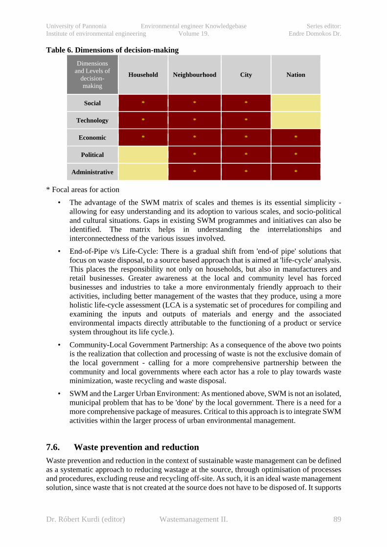
University of Pannonia Environmental engineer Knowledgebase Series editor: Institute of environmental engineering Volume 19. Endre Domokos Dr.
Table 6. Dimensions of decision-making
Dimensions and Levels of
decision-making
Household Neighbourhood City Nation
Social * * *
Technology * * *
Economic * * * *
Political * * *
Administrative * * *
* Focal areas for action • The advantage of the SWM matrix of scales and themes is its essential simplicity -
allowing for easy understanding and its adoption to various scales, and socio-political and cultural situations. Gaps in existing SWM programmes and initiatives can also be identified. The matrix helps in understanding the interrelationships and interconnectedness of the various issues involved.
• End-of-Pipe v/s Life-Cycle: There is a gradual shift from 'end-of pipe' solutions that focus on waste disposal, to a source based approach that is aimed at 'life-cycle' analysis. This places the responsibility not only on households, but also in manufacturers and retail businesses. Greater awareness at the local and community level has forced businesses and industries to take a more environmentaly friendly approach to their activities, including better management of the wastes that they produce, using a more holistic life-cycle assessment (LCA is a systematic set of procedures for compiling and examining the inputs and outputs of materials and energy and the associated environmental impacts directly attributable to the functioning of a product or service system throughout its life cycle.).
• Community-Local Government Partnership: As a consequence of the above two points is the realization that collection and processing of waste is not the exclusive domain of the local government - calling for a more comprehensive partnership between the community and local governments where each actor has a role to play towards waste minimization, waste recycling and waste disposal.
• SWM and the Larger Urban Environment: As mentioned above, SWM is not an isolated, municipal problem that has to be 'done' by the local government. There is a need for a more comprehensive package of measures. Critical to this approach is to integrate SWM activities within the larger process of urban environmental management.
7.6. Waste prevention and reduction Waste prevention and reduction in the context of sustainable waste management can be defined as a systematic approach to reducing wastage at the source, through optimisation of processes and procedures, excluding reuse and recycling off-site. As such, it is an ideal waste management solution, since waste that is not created at the source does not have to be disposed of. It supports
Dr. Róbert Kurdi (editor) Wastemanagement II. 89

University of Pannonia Environmental engineer Knowledgebase Series editor: Institute of environmental engineering Volume 19. Endre Domokos Dr.
sustainable development by fostering environmentally advantageous changes in production and consumption patterns. Examples of waste prevention that can reduce landfill and environmental pollution include donating old cell phones and computers, photocopying on both sides of a sheet of paper, and using fewer hazardous materials in the manufacturing process. In particular, waste prevention can help to reduce:
• demands on finite natural resources and the environmental impacts of resource extraction and harvesting
• the transport impacts that are often so significant in overall health and environmental impact assessments
• the need for waste facilities such as landfill sites and incinerators • the cost of waste management, freeing up resources for other priority investments, such
as cleaner technology, public education and health care
7.7. Conclusion ‘‘Sustainability” is a popular word today. Everyone – from commodity manufacturers and service providers to international policy makers – is using the term in one context or another. It is unclear whether all of these stakeholders understand the term ‘‘sustainable development” to mean the same thing. It has been estimated that current rates of resource extraction are ten thousand times higher than rates of natural resource generation. In the foreseeable future, there is a little chance that this proportion would change significantly. Moreover, it is unclear whether SWM can contribute in a meaningful way. Accordingly, it would be best to develop sustainable SWM rather SWM for sustainable society. The SWM system should be compatible with both the financial capacity of a given society and with the assimilative capacity of its adjoining environment. Although the topic of waste management, as well as the environmental pollution caused by waste, is not a new topic, the need for reasonable and sustainable waste management is one of the most common complaints. Even though, there are a number of laws related to waste management; they do not address waste management in its entire spectrum in most countries. We will have to deal properly with the difficulties in waste management as well as the limits of natural resources if we do not think about the solutions to control and replacing the utilization of resources from the environment by integrated waste management. A vision of zero emissions ecosystems can offer a solution which will be a key of sustainable development to our grandchildren’s future – zero solid waste and zero wastewater. More especially, the use of an endpoint goal of ‘zero’ can promote not only ideas of material reuse and recycling, but also prevention and redesign along the entire product life cycle.
Dr. Róbert Kurdi (editor) Wastemanagement II. 90

University of Pannonia Environmental engineer Knowledgebase Series editor: Institute of environmental engineering Volume 19. Endre Domokos Dr.
8. Methods of Municipal solid waste collection And transportation in regional waste management systems (Buruzs, Adrienn)
8.1. introduction The introduction of the European Union Landfill Directive (‘the Landfill Directive’) in 1999 set targets for all member states to reduce the amount of biodegradable municipal waste disposed to landfill. These have driven the changes in waste management in Hungary and the increases in recycling over the past five years. Waste management services and facilities provided by the municipalities include:
• routinely collecting domestic and commercial refuse • separately collecting recyclable materials such as paper, cardboard and glass for
recycling • collecting garden waste and biodegradable for composting • promoting recycling and educating people so that cities can successfully implement
waste management services • facilities to promote recycling (recycling centers and local recycling facilities) • special arrangements for the collection of hazardous waste • waste treatment facilities, including composting facilities, energy from waste plants,
mechanical biological treatment plants and operating landfill sites. Waste collection used to be regarded as just a part of the larger collection and disposal system. It meant choosing the most appropriate trucks, designing collection routes, and then administering the collection. With present day emphasis on recycling and composting the need to segregate materials has become most important. It can mean different vehicles collecting different material and taking it to different locations. As a result, the collection of wastes has become more complex and more expensive. To meet current needs there is a call for the development of an 'integrated collection strategy' which incorporates the following:
• The system should provide locally appropriate levels of service, designed to meet political, health and regulatory requirements.
• The system should accomplish its requirements at the lowest possible cost • The system should develop local appropriate partnerships between the public and
private sectors • The system should be flexible to meet changing demands • The system should support achievement of waste reduction/diversion targets.
8.2. The quantity, the composition and organized collection of generated municipal solid waste
Waste collection is the component of waste management which results in the passage of a waste material from the source of production to either the point of treatment or final disposal. Waste collection also includes the kerbside collection of recyclable materials that technically are not waste, as part of a municipal landfill diversion program.
Dr. Róbert Kurdi (editor) Wastemanagement II. 91

University of Pannonia Environmental engineer Knowledgebase Series editor: Institute of environmental engineering Volume 19. Endre Domokos Dr.
The quantity of produced municipal solid waste was between 4.5 and 4.9 million tons per year during the period of 2004–2009 and its volume increased slowly. The minimal favorable changes in consumer habits slightly decreased the growing of consumption. There is an unfavorable change in the proportion of weight/volume of MSW. The reason for this is the growing of light – mainly plastic packaging waste – components. One third of municipal solid waste is generated in the Central Hungary Region due to the capital, which contributes to this amount with 26%. The number of inhabitants and the specific quantity of waste, which is in connection with the state of development of a region, determinate the quantity of produced municipal solid waste in a region. For example, despite the fewer number of inhabitants more waste is generated in the Central Transdanubia Region than in the Northern Great Plain Region (see Figure 1).
Figure 1. The specific quantity of generated municipal solid waste in regions in 2004
The composition of produced municipal solid waste has not changed essentially in the last decade. One third of the waste consists of metal, glass, plastic and paper packaging and the other third is biodegradable organic materials (see Figure 2).
Figure 2. The composition of produced municipal solid waste
(Source: The developing strategy of municipal solid waste management 2007–2016)
Dr. Róbert Kurdi (editor) Wastemanagement II. 92

University of Pannonia Environmental engineer Knowledgebase Series editor: Institute of environmental engineering Volume 19. Endre Domokos Dr.
The proportion of utilizable (as secondary raw material) waste is 40-45% (V/V). The ratio of paper (by 25%) and plastic (by 15%) waste will strongly increase in the future (see Figure 3). The ratio of glass and metal waste will slightly increase. The proportion of inorganic (by under 20%) and biodegradable organic (by around 30%) waste will decrease. The calorific value of waste will increase (from 6000-6500 kJ/kg to 7500-8000 kJ/kg). The basic condition of recycling is selective waste collection, which was available for 4.2 million inhabitants (with an average proportion of 1160 persons per collection island in rural areas) in 2006. However, the infrastructure of solid waste collection does not fill every requirement. In other words collection islands are not yet available within 200 meters from every household in every settlement. According to a questionnaire, only 15% of the inhabitants use the current infrastructure of selective waste collection effectively. In Hungary the percentage of selectively collected waste is only 2-3% within the whole amount of collected waste while that percentage achieves 15-20% in Western European countries. As a further aim of the strategy, selective waste collection should have been available for 60% of the inhabitants by 2009 and 80% by 2013. This is statistically possible but the number of citizens who effectively participate in selective waste collection will not increase. Neither will increase the quantity of selectively collected waste if the backbone of selective waste collection is made up of collection islands only.
Figure 3: Analysis of the content of the typical household waste in the EU
Dr. Róbert Kurdi (editor) Wastemanagement II. 93
University of Pannonia Environmental engineer Knowledgebase Series editor: Institute of environmental engineering Volume 19. Endre Domokos Dr.
8.3. Municipal solid waste collection It is estimated that nearly 5 million tones of municipal waste was generated in Hungary in 2009. That is about 500 kg or half a tone of household waste per person. A total of 26,000 tones of this waste were collected separately from households. Although household rubbish represents a relatively small percentage of the total amount of waste produced it is a highly significant proportion because it contains large quantities of organic waste which can cause pollution problems, as well as materials such as glass and plastics which do not break down easily. Waste from our homes is generally collected through regular waste collection, or by special collections for recycling. In Hungary, the waste treatment and collection companies are private or municipality-owned companies charged with the collection and mainly also with the treatment of waste from each household in their area on a regular basis. They can also collect, upon request, commercial and industrial wastes from the private sector. Municipal waste includes all wastes collected by the above mentioned companies, or their agents, such as all household waste, street litter, municipal parks and gardens waste, office waste and some commercial and industrial waste. Legally, the municipalities in Hungary are required by the Environment Protection Act and the Waste Management Act to collect and dispose of municipal waste. This requirement has its origins in the need to protect the health of the population. Despite this, each municipality can make its own decisions as to the method and timing of waste collection. In addition, householders can make special trips to dedicated waste collection points in order to dispose of particular items, such as plastic, glass, paper and metal. This sounds simple enough, but in reality there are numerous ways of collecting household waste. Most companies pick up residual waste (waste that is not intended for recycling or composting) weekly or fortnightly. Some offer an additional recycling collection for biodegradable waste weekly. The methods used to collect residual waste include containers such as regular bins, wheelie bins or plastic sacks. There are many reasons for selecting a particular type of collection infrastructure which may include the method and place of disposal used by the authority, the physical layout for the collection and the current system in place. In addition demographic and cultural factors relating to the population served may be of importance. Although it would appear that the method used to collect residual waste also affects the quantity of waste produced and the participation in recycling schemes, other factors such as the size of households in particular areas may also be of importance.
8.4. household waste recycling Recycling is the first of the three „recovery” processes in the waste hierarchy. Recycling recovers materials, by preventing them from being disposed of, and makes them into new goods. This can involve turning the old material into a new version of the same thing, or materials can be recycled into something completely different. For example, used glass bottles can be recycled into new bottles, or they can be recycled into something different, such materials used in road construction.
Dr. Róbert Kurdi (editor) Wastemanagement II. 94

University of Pannonia Environmental engineer Knowledgebase Series editor: Institute of environmental engineering Volume 19. Endre Domokos Dr.
Recycling is one of the tools available to us to help use resources better and reduce the environmental impacts associated with disposing of rubbish. It can reduce demand for raw materials by extending their life and maximizing the value extracted from them. It can also save energy, and reduce emissions to air and water, in the production process. Not least, recycling helps us become more aware of environmental issues and encourages us to take personal responsibility for the wastes we create. The types of containers (see Figure 4) used are usually plastic or metals cans (55L), wheelie bins (120 - 240L), bags (plastic and/or paper), and special containers such as recycling boxes.
Figure 4: Different types of municipal waste containers
Each type has advantages and disadvantages and must also be related to the setout location. For instance, large wheelie bins will be impractical in narrow urban areas with on-street parking. Bags are susceptible to breakage, and to animal attack, but they are very convenient for collection as they can be picked up and thrown readily. The use of paper bags can provide advantages in composting in that they are easily shredded. The disadvantages of wheelie bins are one of size - most people put out more rubbish to fill the bin. They also require mechanical lifting arms for health and safety reasons, and cost more initially. Interestingly, most wheelie bins are made out of recycled plastic.
8.5. Recycling collections Both the residual waste collection and the management of the collection of recyclable waste can vary from one municipality to the next.
Dr. Róbert Kurdi (editor) Wastemanagement II. 95

University of Pannonia Environmental engineer Knowledgebase Series editor: Institute of environmental engineering Volume 19. Endre Domokos Dr.
The National Waste Management Plan of Hungary has been set targets to increase recycling to between 10 (heat transfer) - 40 (recycling) % over the next years. Recovery targets for municipal waste are: to recover value from 40% of municipal waste by 2014. Householders can take a significant proportion of their household waste to dedicated collection places. There are two main types of recycling collection: waste collection points/islands and waste collection centers. At the waste collection points there are special containers for at least four different types of recycling waste (paper, metal, plastic and glass) (Figure 5). At the waste collection yards householders can place more types of recycling waste (e.g. bulky waste, hazardous waste, green or garden waste, e.g.) (see Figure 6).
Figure 5: Waste collection points for different types of recycling waste
Figure 6: Waste collection yard
Dr. Róbert Kurdi (editor) Wastemanagement II. 96

University of Pannonia Environmental engineer Knowledgebase Series editor: Institute of environmental engineering Volume 19. Endre Domokos Dr.
Material for recycling needs to be clean and uncontaminated, (meaning not mixed with other materials). Problems are caused when the wrong materials are put into the wrong recycling bins. Citizens have to make sure that they wash bottles and cans in leftover washing up water. They always should put the correct materials in the correct recycling bin. Technology is being developed to deal with more mixed and contaminated material, however at present municipalities need to take care in order for recycling to be efficient. Contaminating collected materials this way can make the whole batch unusable for recycling. At both collection places, the householder sorts different materials into different containers, then each material type is separated into different compartments (e.g. recyclable and contamination) at the waste treatment plants.
8.6. charging for waste collection by the polluter-pays-principle The concept of direct charging is used to denote charging for waste by weight, volume or a combination of both. Currently there is no legal provision for this for householders within Hungary, although examples from other countries show that some form of variable charging can strongly influence recycling and waste minimization behavior. Some regions, e.g. Győr and its region have introduced the possibility of fining residents by the polluter-pays-principle that do not take part in the waste selection program and/or do not use the recycling facilities. This, in addition to schemes whereby additional bins are placed to each household in the Győr region for biodegradable waste collection (Figure 6) and waste quantities (e.g. numbers of bin emptied) are monitored by collection vehicle.
Figure 6: Additional container for biodegradable waste collection in Győr region
8.7. KEY POINTS CONCERNING MAIN COLLECTION vehicles The transportation of waste is the movement of waste over a specific area by trains, tankers, trucks, barges, or other vehicles. The types of wastes that may be transported range from municipal garbage to radioactive or hazardous wastes. Hazardous wastes may be transported to be treated, stored, or disposed of. Facilities that generate hazardous waste are required to prepare a shipping document, or "manifest," to accompany the waste as it is transported from the site of generation. This manifest must
Dr. Róbert Kurdi (editor) Wastemanagement II. 97

University of Pannonia Environmental engineer Knowledgebase Series editor: Institute of environmental engineering Volume 19. Endre Domokos Dr.
accompany the waste until its final destination and is used to track the wastes from cradle-to-grave. The potential for pollution releases during the transportation of waste varies; the more hazardous the waste and the larger the volume that is transported, the more devastating the environmental/human health impact if an accident occurs. Traffic accidents or train wrecks can result in waste spills and releases of pollutants that may contaminate the air, water, and soil. Wastes may also be released while being loaded or unloaded during transportation. Due to rapidly decreasing space in urban landfills, officials have been forced to find alternate locations for municipal waste disposal. This has created significant financial incentives for rural communities to accept garbage from urban areas. Depending on the location of these rural facilities, it may be necessary to transport large quantities of wastes by a variety of methods, most often by truck, railway, or barge. Many citizens are concerned about the transportation of the waste through their communities and the risks involved. People are also concerned that the municipal waste from urban areas may be contaminated with toxic chemicals or substances that could contaminate local drinking water supplies. Waste transfer stations are facilities where municipal solid waste is unloaded from collection vehicles and briefly held while it is reloaded onto larger long-distance transport vehicles for shipment to landfills or other treatment or disposal facilities. By combining the loads of several individual waste collection trucks into a single shipment, communities can save money on the labor and operating costs of transporting the waste to a distant disposal site. They can also reduce the total number of vehicular trips traveling to and from the disposal site. Although waste transfer stations help reduce the impacts of trucks traveling to and from the disposal site, they can cause an increase in traffic in the immediate area where they are located. If not properly sited, designed and operated they can cause problems for residents living near them (see Figure 7). Characteristic Features of transfer stations:
1) Improving collection and transport efficiency
• Collection and transport efficiency is improved by delivering about six to eight collection vehicle load of refuse, after repacking it into a container.
2) Hygienic handling
• Because refuse is transported after being packed into closed containers, hygienic transportation is ensured, without refuse scattering.
3) Possibility of flexible dealing with fluctuating amounts of refuse.
• Since containers can storage for compacted refuse, its growing amounts to be handled in the future may be deal with by using additional containers and container loaders.
4) Preservation of ambient environment 5) Labor saving by automatic operation
Dr. Róbert Kurdi (editor) Wastemanagement II. 98

University of Pannonia Environmental engineer Knowledgebase Series editor: Institute of environmental engineering Volume 19. Endre Domokos Dr.
Figure 8: Overview of transfer station
A wide variety of trucks (see Figure 8 and 9) are used for collection. Factors to consider in selecting include:
• the weight of waste that the truck can actually carry
• cost of purchase and operation, including fuel and maintenance
• suitability of the vehicle for the local roads considering width, congestion, and surface conditions
• ease of loading and unloading
• delays in obtaining spare parts.
• Most communities have found that the only way to ensure high participation rates for recycling programs is to provide each participant the most convenient method of participating. In most instances, kerbside pickup is the most convenient, and the trend in recycling is towards some form of kerbside pickup. Drop-off and buy-back centers are not as convenient. Typically, a program using such centers will have lower participation rates.
• Most communities and hauling companies face a dilemma in deciding how best to collect recycled materials, especially those with fleets of refuse vehicles. The prospect of replacing a fleet of refuse trucks with an equally expensive fleet of vehicles designed for recycling is normally not economically feasible, at least at first. As a result, most recycling programs try to use existing refuse equipment to collect recycled materials. Many innovative ideas have been used to convert refuse trucks to all-purpose refuse collection and recycling vehicles.
• Some companies which haul waste from commercial accounts generating high volumes of office paper or cardboard make no attempt to separate the material. Instead, they substitute back-end sorting and processing for separation before collection, separating recyclables out of the waste stream at a processing center in what is known as "dump and pick" operation. Some of these operations have proved
Dr. Róbert Kurdi (editor) Wastemanagement II. 99
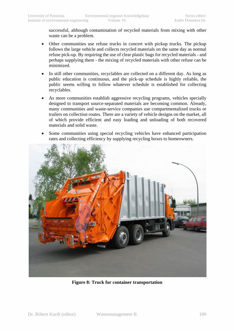
University of Pannonia Environmental engineer Knowledgebase Series editor: Institute of environmental engineering Volume 19. Endre Domokos Dr.
successful, although contamination of recycled materials from mixing with other waste can be a problem.
• Other communities use refuse trucks in concert with pickup trucks. The pickup follows the large vehicle and collects recycled materials on the same day as normal refuse pick-up. By requiring the use of clear plastic bags for recycled materials - and perhaps supplying them - the mixing of recycled materials with other refuse can be minimized.
• In still other communities, recyclables are collected on a different day. As long as public education is continuous, and the pick-up schedule is highly reliable, the public seems willing to follow whatever schedule is established for collecting recyclables.
• As more communities establish aggressive recycling programs, vehicles specially designed to transport source-separated materials are becoming common. Already, many communities and waste-service companies use compartmentalized trucks or trailers on collection routes. There are a variety of vehicle designs on the market, all of which provide efficient and easy loading and unloading of both recovered materials and solid waste.
• Some communities using special recycling vehicles have enhanced participation rates and collecting efficiency by supplying recycling boxes to homeowners.
Figure 8: Truck for container transportation
Dr. Róbert Kurdi (editor) Wastemanagement II. 100

University of Pannonia Environmental engineer Knowledgebase Series editor: Institute of environmental engineering Volume 19. Endre Domokos Dr.
Figure 9: Truck for container transportation
For references see: Buruzs, A., Kovács, B.: A regionális hulladékgazdálkodási rendszerek hulladékgyűjtési és –szállítási módozatai (not published yet.
Dr. Róbert Kurdi (editor) Wastemanagement II. 101
University of Pannonia Environmental engineer Knowledgebase Series editor: Institute of environmental engineering Volume 19. Endre Domokos Dr.
9. COMPOSTING (Bence Fazekas, Viktória Pitás, Peter Thury, Árpád Kárpáti)
9.1. Introduction Composting is practically the same age as human population. Large amounts of organic materials are produced annually in nature that are degraded by microbial action. The decomposition of organic materials takes place slowly on the surface of ground at ambient temperatures. The natural process of degradation can be speeded up by gathering organic material into piles to conserve part of the heat of fermentation so that the temperature of the mass rises and faster reaction rates are attained. This accelerated process of the decomposition of organic matter by a mixed population of microorganisms in a warm, moist, aerobic environment is known as composting. People started to use this process to make compost in the early years, just like the utilization of human faeces. The same stabilization of sewage sludge started only when the practice was forced to purify sewage. The real development of sanitation can be dated from the middle of the 19th century. Some decades after, the overload of receivers made the technological purification of sewage necessary. These technologies became commonly used a lot more centuries after. The further utilization of the residual of wastewater treatment developed parallel with the technology of biological wastewater treatment. The scientific basis of composting has been worked out since the middle of the 20th century and has developed very fast thank to today’s technological improvements.
Dr. Róbert Kurdi (editor) Wastemanagement II. 102
University of Pannonia Environmental engineer Knowledgebase Series editor: Institute of environmental engineering Volume 19. Endre Domokos Dr.
9.2. Composting and its feedstock “Composting is a method of solid waste management whereby the organic component of the solid waste stream is biologically decomposed under controlled conditions to a state in which it can be handled, stored and/or applied to land without adversely affecting the environment” (Golueke, 1977). The process of composting involves an interaction between the organic waste, microorganisms, moisture and oxygen. When the moisture content of the organic waste is brought to a suitable level, and the mass aerated, microbial action speeds up. While attacking organic matter, mixed population of microbes harbouring it multiply and liberate CO2, water, other organic products and energy. A part of the energy is used in metabolism, and the remainder is given off as heat. The end product, compost, is made up of the more resistant residues of the organic matter, breakdown products and dead and living microorganisms along with products formed from further chemical reactions between these materials. The thermal stabilization causes the destruction of pathogen microbes. The solid phase systems are more suited to ensure the biological processes during composting than liquid phase systems. This way composting is practical regarding the mixture of solid and semi-solid materials. As a result of the aerobic biological conversion, the product of composting is CO2 and a stable organic residue with high humus content. The heat coming from the biological oxidation evaporates certain amount of the moisture content of the feedstock. The optimization of moisture content, temperature and oxygen supply is determinative during the process. The first two depends on the quality of the feedstock. During composting, the anaerobic processes play a great role besides the main aerobic one. Anaerobic conditions occur as a result of temporary or local lack of oxygen. It is important regarding the alternation of organic material. It contributes to the formation of easily biodegradable products (organic acids, alcohols) with smaller molecular weight from materials that are difficult to be oxidized biologically. The anaerobic processes have to be controlled because the odorous intermediates can cause undesirable environmental problems. Composting can be a favourable and cost-effective way of organic waste disposal. Compost has several prosperous effects in agricultural use. It increases the humus content of the soil, and thus provides an advantageous soil structure and water holding capacity. It contains further nutrients like nitrogen, phosphorous and several micro-nutrients. And additionally, the release of these nutrients from compost is slow enough not to cause nutrient losses. To specify the product of composting is a controversial issue. The most frequent requirements are the stable, humus-like appearance of the product, being free of pathogens, germs and insects, easy handling and odour-free with appropriate nutrient content. 9.2.1. Compostable materials The list of compostable materials is very long. Agricultural wastes, residuals from food processing, municipal solid waste, solid and liquid manure, forestry wastes, other organic wastes, yard waste and other green wastes (grass, leaves) and sewage sludge coming from municipal wastewater treatment. The main requirement of composting regarding the feedstock is the constant quality and originating amount.
Dr. Róbert Kurdi (editor) Wastemanagement II. 103

University of Pannonia Environmental engineer Knowledgebase Series editor: Institute of environmental engineering Volume 19. Endre Domokos Dr.
9.2.1.1. Municipal sewage sludge
The various organic and inorganic pollutants can be removed in the works of the wastewater treatment plant with variant efficiency depending on their physical and chemical features. Besides the main biotechnological process, mechanical pre-treatment is necessary (screens, grit and grease chambers). The next step in municipal wastewater treatment is usually the primary clarifier. The organic content of the so called primary (raw) sludge arisen is considerable (60-80% organic content, 25-26 000 kJ/kg dry mass energy content). Its conventional stoichiometric formula is C22H39O10N (McCarthy et al.).
In the biological treatment step the dissolved and suspended materials are transformed into biomass via oxidation-reduction biochemical processes or they are incorporated into the sludge flocs or adsorbed on their surface. The separation of the sludge arisen during purification is usually carried out by secondary clarification. The properly designed clarifiers ensure the removal of suspended solids (particles >0,45 µm) from the treated effluent to a level of 20-40 mg/l. The amount of the excess sludge produced via the aerobic treatment of municipal sewage is approximately 50% of the removed organic material. Its organic content varies in a wide range: 60-90%, its average energy content is 20-21000 kJ/kg dry mass. Its conventional stoichiometric formula is C5H7O2N (or regarding the phosphorous content C60H87O23N12P). The yield of excess sludge production during wastewater treatment depends on several parameters (like temperature, technological design, relative biological load, dissolved oxygen concentration etc.). The dry solid content of sludge is 1-3% after secondary clarification, and can reach up to 20-25% after dewatering (belt press, spin dryer etc.).
Considering the further management of these dry residues of wastewater treatment, cost is a determinative factor. It can even be the same as the cost of aeration during purification. According to literature data, 20 kg dry solid of primary sludge and 30 kg dry solid of secondary sludge is produced per inhabitant per year through centralized wastewater treatment.
9.2.1.2. Industrial sewage sludge The produced amount of this kind of sludge is hard to estimate. Residuals and sludge of food processing and in some cases of pharmaceutical and paper industry are excellent feedstock of composting, though one has to be aware of the chemicals used during their production. 9.2.1.3. Manure The whole amount of this kind of waste produced by human beings is collected via drainage as a part of sewage. However, animal husbandry results considerable specific amount of manure (solid and liquid as well). A milking cow produces 75 times, a beef cattle 50 times more manure dry solid than people (in excess sludge dry solid). The manure of different animals varies in moisture content. The driest is horse manure with 60% moisture content, the others are between 70 and 85%. 9.2.1.4. Green (biogenic) waste Green waste is a biodegradable waste that can be composed of garden or park waste, such as grass or flower cuttings and hedge and tree trimmings. Their amount is various and depends on the density of residences and the character of district. In the garden city it can be 10-20% of the
Dr. Róbert Kurdi (editor) Wastemanagement II. 104
University of Pannonia Environmental engineer Knowledgebase Series editor: Institute of environmental engineering Volume 19. Endre Domokos Dr.
whole amount of waste. Yard waste usually consists of 70% grass cuttings, 25% leaves and 5% other residuals. Its amount highly depends on the season. In the former decades green waste was also delivered into landfills. Today it became practice that these kinds of waste are collected separately and composted. Their common feature is the great moisture and nitrogen content. The problem with these materials is that their degradable part can not cover the heat demand of composting. That is why their mixing with carbonaceous waste is of great importance. 9.2.1.5. Food and agricultural waste Several residuals of food processing and agriculture are prominent feedstock of composting. For example: - Potato processing waste, - Starch sludge, - Fish processing waste, - Apple processing waste, - Grape processing waste, - Chocolate production waste, - Food preparation waste, - Agricultural waste. 9.2.1.6. Municipal solid waste This broad category contains all the solid waste that is transported away from human surroundings by organised waste collection. Its amount can be a few hundred kilograms per person per year. It predominantly includes papers, food wastes, yard wastes, containers and product packaging, and other miscellaneous inorganic wastes from residential, commercial, institutional, and industrial sources. The selective collection of plastic and glass is a prerequisite for composting municipal solid waste (MSW). MSW is practically composted at same place as it is collected and separated, adding the required amount of amendment. In waste management, it is a part of mechanical biological treatment (MBT). 9.2.1.7. Special waste This category stands for hazardous industrial waste that start to degrade among the anaerobic conditions of composting with the aid of amendments, and then in the aerobic phase this degradation ends up with a great efficiency. Mainly greasy sludge and residuals of pesticide production can be mentioned here. The favourable conditions of composting can also lead to the degradation of aromatic components (like benzene, phenol, phthalate, polychlorinated biphenyl, PAHs). 9.2.2. Energy recovery from waste Basically, there are three ways of the utilization of the energy content of organic materials: - Getting the nutrient content of organic material into the soil directly or following the composting process, - Transformation of the organic material into energy by burning, methanization or pyrolysis,
Dr. Róbert Kurdi (editor) Wastemanagement II. 105

University of Pannonia Environmental engineer Knowledgebase Series editor: Institute of environmental engineering Volume 19. Endre Domokos Dr.
- Recycling of the organic material into production (like paper, plastic). Considering the most favourable way of reuse, the determinative features are the consistence of waste and the technical and economical conditions. Regarding pre-separated dry waste (like forestry residuals or MSW) the most advantageous procedure is burning, pyrolysis or methanization. The efficiency of incineration decreases as the moisture content of waste increases. The requirement of self-supporting burning is the moisture content below 60-70%. In case of sludge suspension, the only way of energy recovery is anaerobic digestion. The incineration of the residuals of anaerobic digestion (sludge with high moisture content but with lower heating value) is not cost-effective enough in most cases. Their injection into soil is regionally limited. The main advantage of composting is its flexibility. It transforms the feedstock with high moisture content into a drier product that can be handled easier. It stabilizes organic materials that are prone to rotten, and strongly reduces the number of pathogens with minimal outer energy demand. 9.2.2.1. Problems with wet feedstock The problem with direct composting of the sludge residuals of municipal and industrial wastewater treatment is their high moisture content (70-80%). One main rule of composting is that the higher is the moisture content of the feedstock, the higher free pore space is needed in the compost pile to ensure the required amount of air. Sewage sludge is prone to compaction because of the great moisture content and the lack of porosity. That is the reason why sludge has to be dewatered or pre-dried before composting. It is also important to shelter the compost pile from the environmental effects (like fall). Besides the outlined disadvantages, sludge has got several advantageous features: it is homogenous and free of unwanted lumpy impurities. It contains all of the nutrients required in composting (N, P and micronutrients), and the only intervention needed is minimal pre- or post-treatment besides the adjustment of moisture content. 9.2.2.2. Problems with dry feedstock Dry feedstock (agricultural waste, MSW and green waste) also have their own limits. They are heterogeneous to a great extent that makes the pre-selection and sometimes even the grinding necessary before composting. Their lack of nitrogen is general. In some cases, it is requisite to moisture these kinds of waste. The similar feedstock can differ from each other basically. Among green waste, leaves and grass are collected and composted together, although their ratio is determinative to the speed and equilibrium of the process. Leaves have good mechanical stability, but they degrade slowly and their nitrogen content is unfavourable. On the contrary, grass is prone to exaggerated compaction, has high nitrogen content and is composted very fast. Therefore grass can easily rotten and cause odour emission. All the potential feedstock of composting has their own specialities that have to be exactly known by the designer.
Dr. Róbert Kurdi (editor) Wastemanagement II. 106
University of Pannonia Environmental engineer Knowledgebase Series editor: Institute of environmental engineering Volume 19. Endre Domokos Dr.
9.2.2.3. Product quality requirements Parameters of the feedstock definitely determine the quality of the product. It mainly serves the health care and environmental quality assurance by means of product quality requirements. Problems of pathogens can be eliminated by the properly kept temperature of the compost pile. Limit values are enforced to avoid the heavy metal pollution of the environment and the accumulation of heavy metals in the food chain. The demonstration of these limit values is beside the subject of the present study. Commercial compost product has several quality requirements that are not in connection with health or environmental effects. Such attributes are the colour and particle size of the product, presence of weed cores, glass shatter, plastic, the organic content, C/N ratio, salinity, pH, moisture content and water holding capacity of the compost. 9.2.2.4. Theory and practice Composting is a complex process that involves controversial issues. However, it has been applied securely for a long time. Rapid proceeding seems to be the best but it results in such heat generation that biological processes may slow down, or even stop. That is why feedstock with high energy content are not favourable oneselves. Flexible operation ensures degrading to a great extent besides permanent temperature. 9.3. Amendments of sewage sludge composting One possible amendment of composting is green waste that is previously detailed also as a feedstock of composting. Other possible category of amendments is the wide range of agricultural and forestry waste (to mention the most important ones: straw, corn- and sunflower-stalk, corn-cob, wood chips and sawdust). All the potential amendments of composting have their own specialities that have to be exactly known by the designer, just like in case of feedstock. However, amendments become feedstock at the moment they are added to the feedstock.
As upper mentioned, one main rule of composting is that the higher is the moisture content of the feedstock, the higher free air volume is needed in the compost pile to ensure the required amount of air. Sewage sludge is prone to compaction because of the great moisture content and the lack of porosity. That is why dewatering and the adding of amendments are needed.
9.3.1. Conditioning the feedstock
Moist sewage sludge has never been suitable itself for composting, except for those experimental plants that can ensure continuous mixing. Their inclination to compaction cuts the air out form the solid phase. Intensive mixing is the only way to ensure suitable air supply. On the other hand, too dry feedstock makes moisturizing necessary. In some cases the adjustment of nutrient content is also required to avoid the slowing down of biological processes in the lack of the needed nutrients.
Once the biological processes have started, operators have only a few possibilities to control them. That makes the conditioning of feedstock fundamental. During mixed composting (dewatered sewage sludge and amendments) the designer has to adjust the moisture content, specific volume and free pore space ratio, porosity and the recoverable energy content in the
Dr. Róbert Kurdi (editor) Wastemanagement II. 107
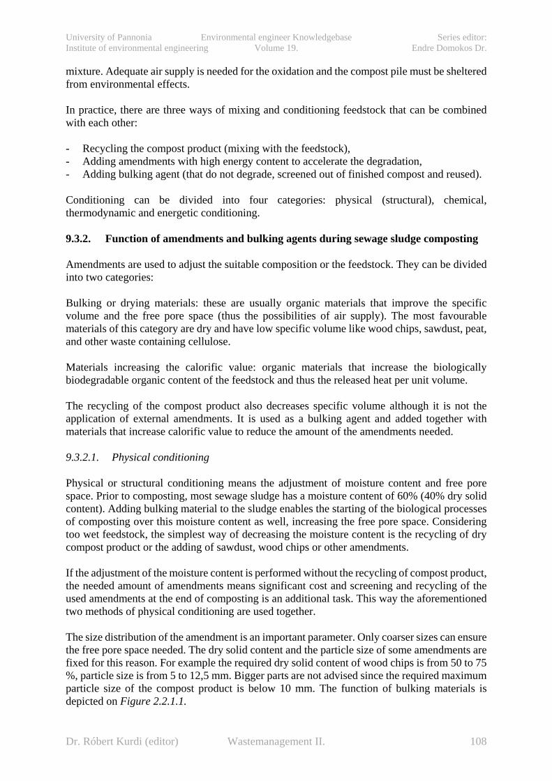
University of Pannonia Environmental engineer Knowledgebase Series editor: Institute of environmental engineering Volume 19. Endre Domokos Dr.
mixture. Adequate air supply is needed for the oxidation and the compost pile must be sheltered from environmental effects.
In practice, there are three ways of mixing and conditioning feedstock that can be combined with each other:
- Recycling the compost product (mixing with the feedstock), - Adding amendments with high energy content to accelerate the degradation, - Adding bulking agent (that do not degrade, screened out of finished compost and reused).
Conditioning can be divided into four categories: physical (structural), chemical, thermodynamic and energetic conditioning.
9.3.2. Function of amendments and bulking agents during sewage sludge composting
Amendments are used to adjust the suitable composition or the feedstock. They can be divided into two categories:
Bulking or drying materials: these are usually organic materials that improve the specific volume and the free pore space (thus the possibilities of air supply). The most favourable materials of this category are dry and have low specific volume like wood chips, sawdust, peat, and other waste containing cellulose.
Materials increasing the calorific value: organic materials that increase the biologically biodegradable organic content of the feedstock and thus the released heat per unit volume.
The recycling of the compost product also decreases specific volume although it is not the application of external amendments. It is used as a bulking agent and added together with materials that increase calorific value to reduce the amount of the amendments needed.
9.3.2.1. Physical conditioning
Physical or structural conditioning means the adjustment of moisture content and free pore space. Prior to composting, most sewage sludge has a moisture content of 60% (40% dry solid content). Adding bulking material to the sludge enables the starting of the biological processes of composting over this moisture content as well, increasing the free pore space. Considering too wet feedstock, the simplest way of decreasing the moisture content is the recycling of dry compost product or the adding of sawdust, wood chips or other amendments.
If the adjustment of the moisture content is performed without the recycling of compost product, the needed amount of amendments means significant cost and screening and recycling of the used amendments at the end of composting is an additional task. This way the aforementioned two methods of physical conditioning are used together.
The size distribution of the amendment is an important parameter. Only coarser sizes can ensure the free pore space needed. The dry solid content and the particle size of some amendments are fixed for this reason. For example the required dry solid content of wood chips is from 50 to 75 %, particle size is from 5 to 12,5 mm. Bigger parts are not advised since the required maximum particle size of the compost product is below 10 mm. The function of bulking materials is depicted on Figure 2.2.1.1.
Dr. Róbert Kurdi (editor) Wastemanagement II. 108
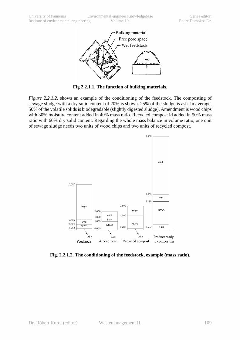
University of Pannonia Environmental engineer Knowledgebase Series editor: Institute of environmental engineering Volume 19. Endre Domokos Dr.
Fig 2.2.1.1. The function of bulking materials.
Figure 2.2.1.2. shows an example of the conditioning of the feedstock. The composting of sewage sludge with a dry solid content of 20% is shown. 25% of the sludge is ash. In average, 50% of the volatile solids is biodegradable (slightly digested sludge). Amendment is wood chips with 30% moisture content added in 40% mass ratio. Recycled compost id added in 50% mass ratio with 60% dry solid content. Regarding the whole mass balance in volume ratio, one unit of sewage sludge needs two units of wood chips and two units of recycled compost.
Fig. 2.2.1.2. The conditioning of the feedstock, example (mass ratio).
Dr. Róbert Kurdi (editor) Wastemanagement II. 109
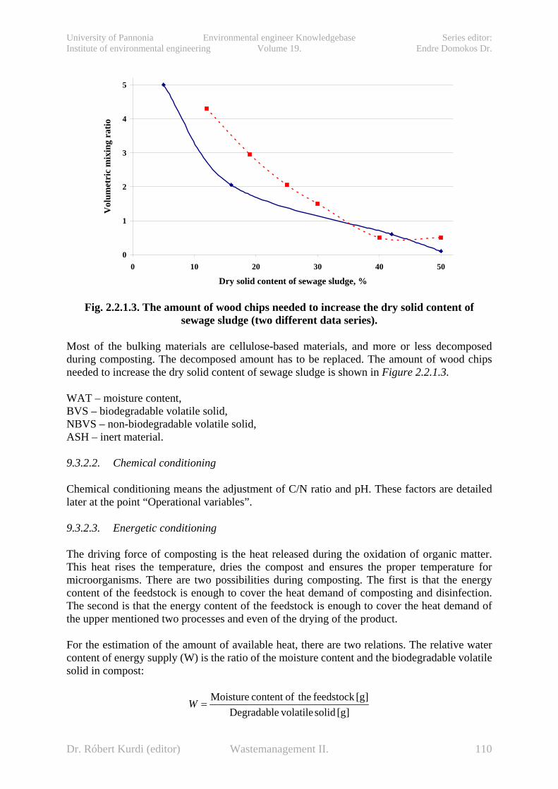
University of Pannonia Environmental engineer Knowledgebase Series editor: Institute of environmental engineering Volume 19. Endre Domokos Dr.
Fig. 2.2.1.3. The amount of wood chips needed to increase the dry solid content of
sewage sludge (two different data series).
Most of the bulking materials are cellulose-based materials, and more or less decomposed during composting. The decomposed amount has to be replaced. The amount of wood chips needed to increase the dry solid content of sewage sludge is shown in Figure 2.2.1.3.
WAT – moisture content, BVS – biodegradable volatile solid, NBVS – non-biodegradable volatile solid, ASH – inert material.
9.3.2.2. Chemical conditioning
Chemical conditioning means the adjustment of C/N ratio and pH. These factors are detailed later at the point “Operational variables”.
9.3.2.3. Energetic conditioning
The driving force of composting is the heat released during the oxidation of organic matter. This heat rises the temperature, dries the compost and ensures the proper temperature for microorganisms. There are two possibilities during composting. The first is that the energy content of the feedstock is enough to cover the heat demand of composting and disinfection. The second is that the energy content of the feedstock is enough to cover the heat demand of the upper mentioned two processes and even of the drying of the product.
For the estimation of the amount of available heat, there are two relations. The relative water content of energy supply (W) is the ratio of the moisture content and the biodegradable volatile solid in compost:
[g] solid volatileDegradable[g]feedstock theofcontent Moisture
=W
0
1
2
3
4
5
0 10 20 30 40 50
Dry solid content of sewage sludge, %
Vol
umet
ric
mix
ing
ratio
Dr. Róbert Kurdi (editor) Wastemanagement II. 110
University of Pannonia Environmental engineer Knowledgebase Series editor: Institute of environmental engineering Volume 19. Endre Domokos Dr.
The water that is formed during composting is approximately the same amount as the water content of the product. This indicates that almost the whole amount of the water content of the feedstock has to be evaporated. Practically, 8-10 gramms of water/gramm biodegradable volatile solid (W) can be evaporated during composting. If W<8, the energy content is enough to cover the heat demand of evaporation, if W>10, the energy content of the feedstock itself is not enough, amendments with high calorific value are needed.
Another relation takes the heating value of the feedstock into consideration as well. It is called relative energy content (E; [cal/g H2O]). Referring to the upper mentioned example, 0,48 kg biologically degradable volatile solids with a heating value of 5500 kcal/kg mean an energy content of 2664 kcal. Dividing it with the 4 kilogramms of water that needs to be evaporated, the relative energy content is 666 cal/g H2O. According to the experiences, 700 cal/g H2O is enough for heating and drying. If E<600 cal/g H2O, the required temperature can be maintained but the degree of drying decreases.
Raw sewage sludge with 20% dry solid content, 65% biodegradable volatile solid and 5500 kcal/kg heating value results W=7,69 and E=720 cal/g H2O. According to this calculation, conditioning of the feedstock is unnecessary. On the contrary, digested sewage sludge with 20% dry solid content, 45% biodegradable volatile solid and 5500 kcal/kg heating value indicates W=16,2 and E=343 cal/g H2O. Digested sewage sludge cannot cover the heat demand of composting and drying at the same time without conditioning the feedstock. The possibilities are: Adding amendment with high calorific value or pre-drying the sewage sludge. Recycling of the compost product doesn’t increase the degradable organic matter content of the feedstock.
9.3.2.4. Oxygen demand of the oxidation of organic matter
Stoichiometric oxygen demand can be calculated based on the chemical composition of the materials. Average composition of raw sludge is C22H39O10N, of mixed sludge is C10H10O3N. It can also be calculated based on the average composition of the feedstock (C31H50O26N) and the product (C11H14O4N). Taking the ash content into consideration, too, the demand is 2 kgs of air/kgs of dry volatile solid. But in practice, it can be higher with one order of magnitude. The amount of water needs to be evaporated can be calculated based on the mass balance of composting. It is determined by the moisture content of sludge (Figure 2.2.4.). If it is less than 30%, the required moisture content of the product is also determinative. The oxygen demand of composting also depends on the phase of composting process. The peak of oxygen demand occurs in the phase of high degradation rate for about 2 days between 40-65 °C (10-14 mg O2 / g volatile solid*h). In the next 4 days the 3/4th of it is needed, and in the next 8 days half of it. For lack of the required amount of air, the temperature of the pile rises too high (without cooling). Curing can happen in static piles with spontaneous aeration.
Dr. Róbert Kurdi (editor) Wastemanagement II. 111

University of Pannonia Environmental engineer Knowledgebase Series editor: Institute of environmental engineering Volume 19. Endre Domokos Dr.
Fig. 2.2.4. The effect of the moisture content of digested sewage sludge on the amount of
water that must be evaporated during composting.
9.4. Main steps of sewage sludge composting
The composting process itself can be divided into two phases: high-rate degradation and curing. High-rate degradation is the thermophilic part of the process (50-70°C). During the high-rate degradation phase, volume and mass are reduced by the degradation of the easily degradable material that is usually responsible for most intense odour emissions. Additionally, pathogens are destroyed due to thermophilic temperatures. Later the temperature decreases, the degradation continues and the organic matter is further stabilised. During curing, the compost matures. Ambient temperatures are reached and the previously started humification continues. Due to higher biological activity and stronger odour emissions, high-rate degradation step require more process control compared to curing. However curing has the same importance since this phase determines the final appearance of the product. Curing is not finished when the process of composting is over, that is why compost is a long-term fertiliser for soil.
9.4.1. Pre- and post-treatment 9.4.1.1. Sewage sludge
As the first step of composting, the sewage sludge is mixed with the amendment to adjust the feedstock’s chemical, physical and biological properties. The most widely used amendments are food chips, sawdust and straw. Amendments may require shredding. Pre-treatment stands for the mixing of the components and the recycled compost product with mechanical devices. For post-processing, the compost is screened if the bulking agent is reused or if a compost with a specified particle size is requested.
The biodegradability of the feedstock also affects the process of composting. The biodegradable part of materials can be calculated based on their lignin content with the following relation:
(0,028)X - 0,830 B =
where B = biodegradable part of volatile solid, X = lignin content in % of the volatile solid.
Dr. Róbert Kurdi (editor) Wastemanagement II. 112

University of Pannonia Environmental engineer Knowledgebase Series editor: Institute of environmental engineering Volume 19. Endre Domokos Dr.
9.4.1.2. Operational variables 9.4.1.2.1. Aeration
During aerobic metabolism, a sufficient supply of oxygen is essential. Regardless of the feedstock or the selected technology, a minimal free pore space of 20-30% is recommended for sufficient oxygen supply. Besides supplying oxygen, aeration has the function of drying the compost and controlling temperatures in the compost that could be detrimental to microorganisms. At the beginning of the composting process, the high degradation rate results in a high oxygen demand compared to average oxygen demand. Oxygen can be provided by active aeration, by natural ventilation of to a lesser extent by turning.
9.4.1.2.2. C/N ratio An optimal nutrient composition is necessary for the microbial processes to start during composting. Suitable C/N ratios at the beginning of composting process are between 25:1 to 35:1. Too high C/N ratio refers to high portion of hardly biodegradable materials, and too low C/N ratio means that easily biodegradable materials are dominant in the mixture. Further addition of N and P nutrients might be reasonable. Additives like lime, bentonite and clay can improve the mineral content of the compost.
C/N ratios of some feedstock: - sawdust 500:1 - carton, paper 350:1 - straw ( (corn, oat) 100:1 - straw (rye, barley) 60:1 - green waste 40:1 - cattle manure 25:1 - kitchen waste 15:1 - sewage sludge 10-15:1 9.4.1.2.3. Moisture content
Moisture is essential to the decomposition process, since most microbial decomposition occurs in thin liquid films on the surface of particles. Microorganisms absorb dissolved nutrients and water serves as a medium for distribution within the heterogeneous compost substrate. The minimum required moisture content for microbial degradation ranges between 12-25%. The optimum moisture content for sewage sludge varies depending on the coarseness of the feedstock and the composting technology used. Initial moisture content of 55-60% is recommended. Agitated bed systems with daily turning can handle moisture contents of 60-65%. At the end of the composting process, the finished compost should not have moisture content higher than 40-45%. The control of moisture content during composting is essential to maintain biological processes and to avoid the anaerobic conditions.
9.4.1.2.4. pH range and temperature
Dr. Róbert Kurdi (editor) Wastemanagement II. 113
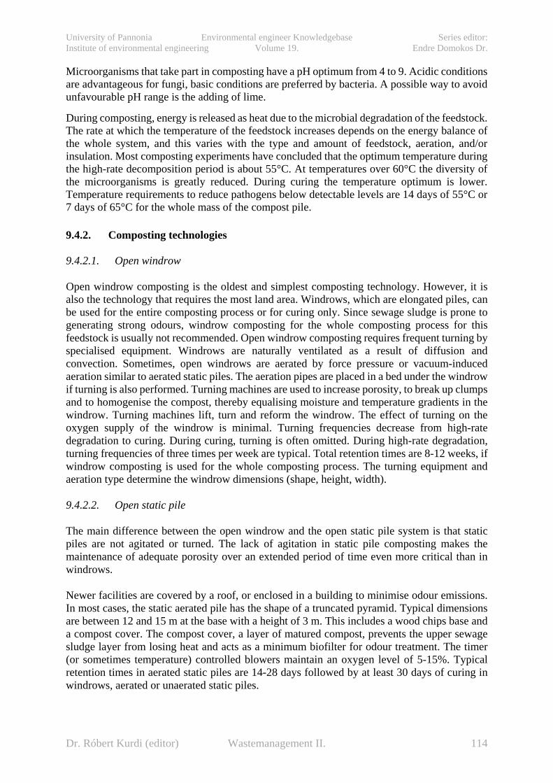
University of Pannonia Environmental engineer Knowledgebase Series editor: Institute of environmental engineering Volume 19. Endre Domokos Dr.
Microorganisms that take part in composting have a pH optimum from 4 to 9. Acidic conditions are advantageous for fungi, basic conditions are preferred by bacteria. A possible way to avoid unfavourable pH range is the adding of lime.
During composting, energy is released as heat due to the microbial degradation of the feedstock. The rate at which the temperature of the feedstock increases depends on the energy balance of the whole system, and this varies with the type and amount of feedstock, aeration, and/or insulation. Most composting experiments have concluded that the optimum temperature during the high-rate decomposition period is about 55°C. At temperatures over 60°C the diversity of the microorganisms is greatly reduced. During curing the temperature optimum is lower. Temperature requirements to reduce pathogens below detectable levels are 14 days of 55°C or 7 days of 65°C for the whole mass of the compost pile. 9.4.2. Composting technologies 9.4.2.1. Open windrow
Open windrow composting is the oldest and simplest composting technology. However, it is also the technology that requires the most land area. Windrows, which are elongated piles, can be used for the entire composting process or for curing only. Since sewage sludge is prone to generating strong odours, windrow composting for the whole composting process for this feedstock is usually not recommended. Open windrow composting requires frequent turning by specialised equipment. Windrows are naturally ventilated as a result of diffusion and convection. Sometimes, open windrows are aerated by force pressure or vacuum-induced aeration similar to aerated static piles. The aeration pipes are placed in a bed under the windrow if turning is also performed. Turning machines are used to increase porosity, to break up clumps and to homogenise the compost, thereby equalising moisture and temperature gradients in the windrow. Turning machines lift, turn and reform the windrow. The effect of turning on the oxygen supply of the windrow is minimal. Turning frequencies decrease from high-rate degradation to curing. During curing, turning is often omitted. During high-rate degradation, turning frequencies of three times per week are typical. Total retention times are 8-12 weeks, if windrow composting is used for the whole composting process. The turning equipment and aeration type determine the windrow dimensions (shape, height, width).
9.4.2.2. Open static pile
The main difference between the open windrow and the open static pile system is that static piles are not agitated or turned. The lack of agitation in static pile composting makes the maintenance of adequate porosity over an extended period of time even more critical than in windrows.
Newer facilities are covered by a roof, or enclosed in a building to minimise odour emissions. In most cases, the static aerated pile has the shape of a truncated pyramid. Typical dimensions are between 12 and 15 m at the base with a height of 3 m. This includes a wood chips base and a compost cover. The compost cover, a layer of matured compost, prevents the upper sewage sludge layer from losing heat and acts as a minimum biofilter for odour treatment. The timer (or sometimes temperature) controlled blowers maintain an oxygen level of 5-15%. Typical retention times in aerated static piles are 14-28 days followed by at least 30 days of curing in windrows, aerated or unaerated static piles.
Dr. Róbert Kurdi (editor) Wastemanagement II. 114
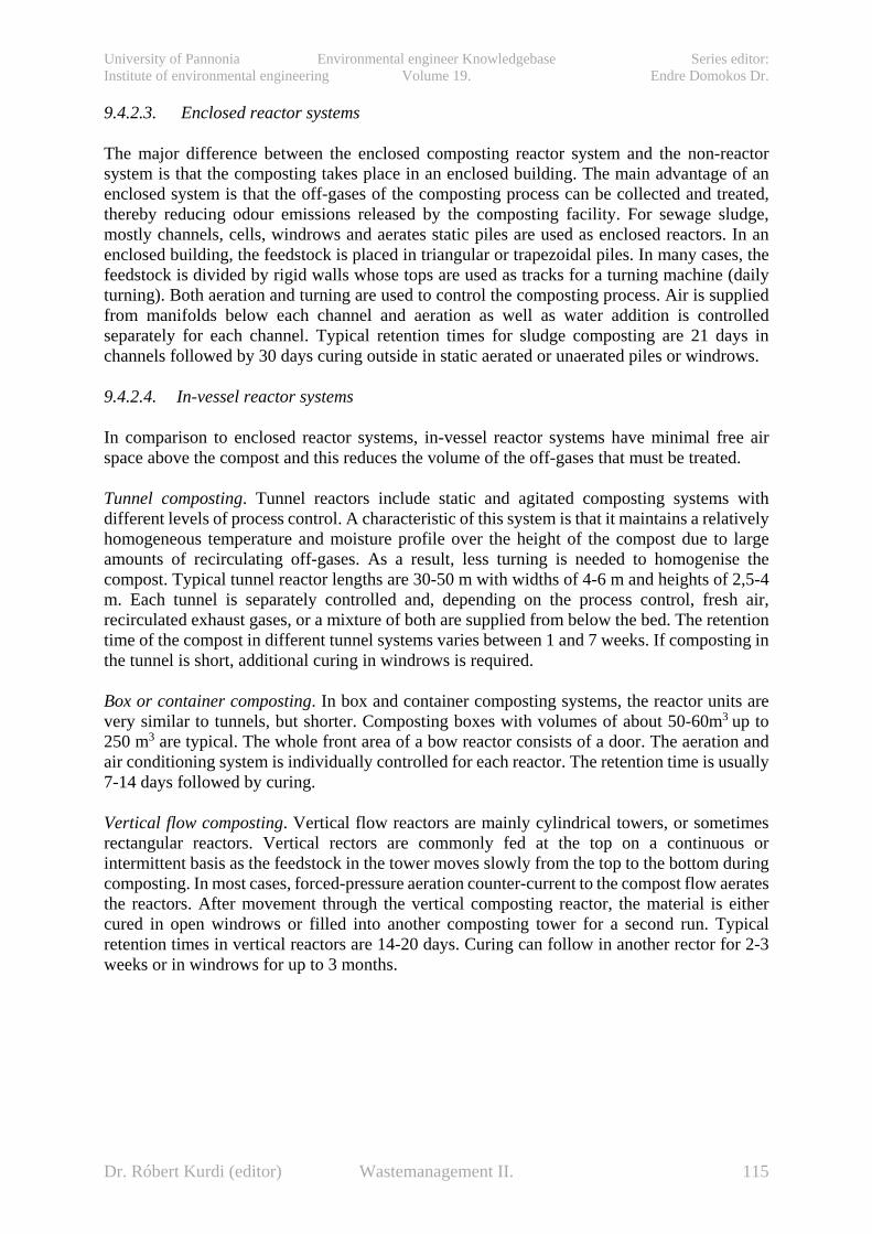
University of Pannonia Environmental engineer Knowledgebase Series editor: Institute of environmental engineering Volume 19. Endre Domokos Dr.
9.4.2.3. Enclosed reactor systems
The major difference between the enclosed composting reactor system and the non-reactor system is that the composting takes place in an enclosed building. The main advantage of an enclosed system is that the off-gases of the composting process can be collected and treated, thereby reducing odour emissions released by the composting facility. For sewage sludge, mostly channels, cells, windrows and aerates static piles are used as enclosed reactors. In an enclosed building, the feedstock is placed in triangular or trapezoidal piles. In many cases, the feedstock is divided by rigid walls whose tops are used as tracks for a turning machine (daily turning). Both aeration and turning are used to control the composting process. Air is supplied from manifolds below each channel and aeration as well as water addition is controlled separately for each channel. Typical retention times for sludge composting are 21 days in channels followed by 30 days curing outside in static aerated or unaerated piles or windrows.
9.4.2.4. In-vessel reactor systems
In comparison to enclosed reactor systems, in-vessel reactor systems have minimal free air space above the compost and this reduces the volume of the off-gases that must be treated.
Tunnel composting. Tunnel reactors include static and agitated composting systems with different levels of process control. A characteristic of this system is that it maintains a relatively homogeneous temperature and moisture profile over the height of the compost due to large amounts of recirculating off-gases. As a result, less turning is needed to homogenise the compost. Typical tunnel reactor lengths are 30-50 m with widths of 4-6 m and heights of 2,5-4 m. Each tunnel is separately controlled and, depending on the process control, fresh air, recirculated exhaust gases, or a mixture of both are supplied from below the bed. The retention time of the compost in different tunnel systems varies between 1 and 7 weeks. If composting in the tunnel is short, additional curing in windrows is required.
Box or container composting. In box and container composting systems, the reactor units are very similar to tunnels, but shorter. Composting boxes with volumes of about 50-60m3 up to 250 m3 are typical. The whole front area of a bow reactor consists of a door. The aeration and air conditioning system is individually controlled for each reactor. The retention time is usually 7-14 days followed by curing.
Vertical flow composting. Vertical flow reactors are mainly cylindrical towers, or sometimes rectangular reactors. Vertical rectors are commonly fed at the top on a continuous or intermittent basis as the feedstock in the tower moves slowly from the top to the bottom during composting. In most cases, forced-pressure aeration counter-current to the compost flow aerates the reactors. After movement through the vertical composting reactor, the material is either cured in open windrows or filled into another composting tower for a second run. Typical retention times in vertical reactors are 14-20 days. Curing can follow in another rector for 2-3 weeks or in windrows for up to 3 months.
Dr. Róbert Kurdi (editor) Wastemanagement II. 115
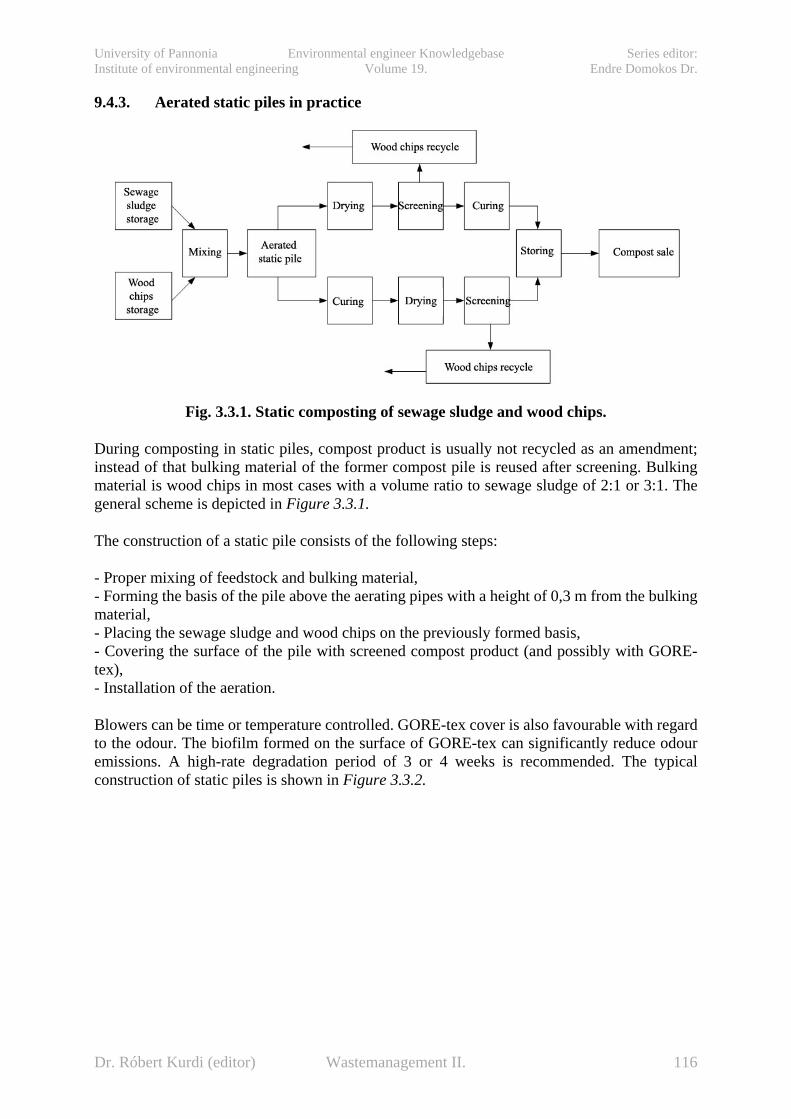
University of Pannonia Environmental engineer Knowledgebase Series editor: Institute of environmental engineering Volume 19. Endre Domokos Dr.
9.4.3. Aerated static piles in practice
Fig. 3.3.1. Static composting of sewage sludge and wood chips.
During composting in static piles, compost product is usually not recycled as an amendment; instead of that bulking material of the former compost pile is reused after screening. Bulking material is wood chips in most cases with a volume ratio to sewage sludge of 2:1 or 3:1. The general scheme is depicted in Figure 3.3.1.
The construction of a static pile consists of the following steps:
- Proper mixing of feedstock and bulking material, - Forming the basis of the pile above the aerating pipes with a height of 0,3 m from the bulking material, - Placing the sewage sludge and wood chips on the previously formed basis, - Covering the surface of the pile with screened compost product (and possibly with GORE-tex), - Installation of the aeration.
Blowers can be time or temperature controlled. GORE-tex cover is also favourable with regard to the odour. The biofilm formed on the surface of GORE-tex can significantly reduce odour emissions. A high-rate degradation period of 3 or 4 weeks is recommended. The typical construction of static piles is shown in Figure 3.3.2.
Dr. Róbert Kurdi (editor) Wastemanagement II. 116
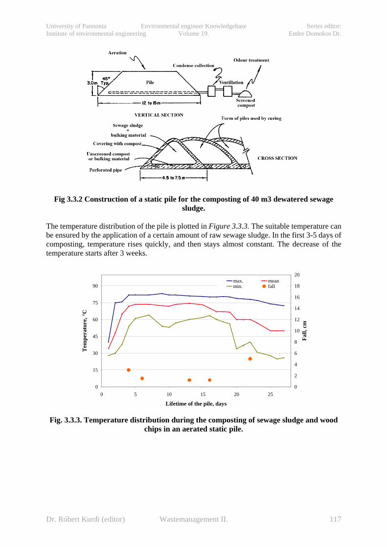
University of Pannonia Environmental engineer Knowledgebase Series editor: Institute of environmental engineering Volume 19. Endre Domokos Dr.
Fig 3.3.2 Construction of a static pile for the composting of 40 m3 dewatered sewage
sludge.
The temperature distribution of the pile is plotted in Figure 3.3.3. The suitable temperature can be ensured by the application of a certain amount of raw sewage sludge. In the first 3-5 days of composting, temperature rises quickly, and then stays almost constant. The decrease of the temperature starts after 3 weeks.
Fig. 3.3.3. Temperature distribution during the composting of sewage sludge and wood
chips in an aerated static pile.
0
15
30
45
60
75
90
0 5 10 15 20 25
Lifetime of the pile, days
Tem
pera
ture
, °C
0
2
4
6
8
10
12
14
16
18
20
Fall,
cm
max. meanmin. fall
Dr. Róbert Kurdi (editor) Wastemanagement II. 117

University of Pannonia Environmental engineer Knowledgebase Series editor: Institute of environmental engineering Volume 19. Endre Domokos Dr.
Figure 3.3.4. shows the temperature profiles of composting different sewage sludge with
different amendments.
Fig. 3.3.4. The temperature profile of composting different sewage sludge with different amendments in an aerated static pile. Each measuring point is the mean of the temperature of 10 different points in
the cross-section of the pile.
The time needed for the curing of the screened, pre-treated compost after high-degradation phase varies between 30 to 60 days. It is usually carried out in aerated piles with occasional aeration.
The example given in Figure 3.3.4. stands for the composting of 200 tons of sewage sludge with 20% dry solid content. The volume of the wood chips used is 3/5th of the volume of sewage sludge during the three-week rapid composting. As it is shown in the Figure, the amount of recycled, screened wood chips is 8 times the fresh one. There is another inner recycle stream: 1,5 times the volume of sewage sludge is unscreened compost recycle (structural conditioning and inoculum). Curing also means a significant reduction in volume. The mass balance of the static pile is detailed in Table 3.3.1.
Fig. 3.3.4. Scheme of an aerated static pile composting
40
45
50
55
60
65
70
75
80
1 4 6 7 8 10 11 12,5 17 18 19 20
,5 22 25 26 27 28 29
Lifetime of the pile, days
Tem
pera
ture
, °C
1:1 sludge/rice peel ratio1:1:1 sludge/compost/wood chips1:2 sludge/rec. compost
Dr. Róbert Kurdi (editor) Wastemanagement II. 118

University of Pannonia Environmental engineer Knowledgebase Series editor: Institute of environmental engineering Volume 19. Endre Domokos Dr.
Table 3.3.1. Mass balance of an aerated static pile. Point (Stream)
1 2 3 4 5 6 7 8 9
Tons of dry solid/d 40 205 20 245 78 245 194 50 45 Dry solid content, % 20 58 53,4 44,2 52,6 52,6 55 55 58 Wet tons/d 200 410 37 554 148 466 352 91 77,5 t/m3 1,18 0,61 0,39 0,82 0,60 0,60 0,52 0,79 0,86 m3/d 169 675 95,5 675 245 771 675 115 90 V/Vwood chips 2 8 1 8 3 10 8 1,5 1 V/Vsewage sludge 1 4 0,5 4 1,5 5 4 0,75 0,5
Fig. 3.3.5. Performance of air blowers by the static pile composting of raw sewage sludge
with 25% dry solid content and bulking materials.
The great development of the 80’s in static pile composting was the realisation of the need for the control of aeration based on oxygen demand. Along with the temperature’s reduction to an optimum level, the rate of degradation and its heat production increased the evaporized amount of water. The amount of air inlet changed according to temperature-based control (Figure3.3.5.).
Oxygen demand is significant in the first week of composting, and then it is reducing continuously. High performance air blowers are needed to cover the great demand of aeration when the maximal amount of air is needed. The suitable blower capacity is 15 m3 h /tons of dry solid. Temperature-based control ensures that the oxygen content of the pile varies between 5 to 15 %. A few-day-long quick composting may even require 150 m3 h /tons of dry solid capacity. The set-point of temperature is favourably 55 to 65 °C to ensure disinfection as well during municipal sewage sludge composting. This set-point can be decreased as the end of composting approaches.
For the proper heat-sterilization, enough released heat is required arisen by the oxidation of organic matter. One cornerstone of design is the calorific value of the feedstock (Table 3.3.2.).
Dr. Róbert Kurdi (editor) Wastemanagement II. 119

University of Pannonia Environmental engineer Knowledgebase Series editor: Institute of environmental engineering Volume 19. Endre Domokos Dr.
Table 3.3.2. Energy content of some feedstock.
Feedstock Calorific value (kcal/g)
Dry wood 3,1 Raw sewage sludge (without water and ash) 5,5 Digested sewage sludge (without water and ash) 2,9
Considering that the ash content of digested sewage sludge is almost 50% of the organic matter, its energy content/dry solid is 2 kcal/g. Calorific value is always greater than heating value since a part of the energy content is used for the evaporization of moisture content and heating. The reason why the energy content of digested sewage sludge is almost the half of raw sewage sludge is the reduction in organic matter caused by methanization and the fact that the remained organic matter is biologically harder to degrade.
Dr. Róbert Kurdi (editor) Wastemanagement II. 120

University of Pannonia Environmental engineer Knowledgebase Series editor: Institute of environmental engineering Volume 19. Endre Domokos Dr.
10. Approaches to waste classification and treatment in nuclear industry (István Szűcs)
10.1. Challenges of radioactive waste classification Radioactive waste (or radwaste, is ― in connection of human activities ― mainly generated from the production of nuclear industry and from the use of radioactive materials in industrial applications, research and medicine) refers to those materials without a foreseen use that are considered appropriate for control as radioactive waste by the regulatory body. As it is generated in a number of different kinds of facilities it may arise in a wide range of concentrations of radionuclides and in a variety of physical and chemical forms as well.
Any radwaste classification ― is realized by selecting the main features (criteria) and by structuring these criteria ― may be more or less depending on the number of classes and the criteria considered and derived from different points of view, such as regulatory issues, process engineering demands or safety related aspects.
There are lots of different quantity or concentration limits for the classification of radioactive waste are to be recommended by international organizations and established by regulatory bodies of every states. Since a considerable experience has long been gained in this field the importance of safe management of radioactive waste for the protection of human health and the environment has been recognized and regulated.
According to the IAEA SS No. 111-G-1.1 (1994) [1] „classification of radioactive waste will serve many purposes:
• at the conceptual level:
o in devising waste management strategies;
o in planning and designing waste management facilities;
o in designating radioactive waste to a particular conditioning technique or disposal facility;
• at the operational level:
o by defining operational activities and in organizing the work with waste;
o by giving a broad indication of the potential hazards involved with the various types of radioactive waste;
o by facilitating record keeping;
• for communication:
o by providing words or acronyms universally understood which improve communication among experts from different countries, and between experts, generators and managers of radwaste, regulators and the public”.
10.2. International classification of nuclear wastes
As it is illustrated on the Fig. 1.1. the following six classes (and their qualitative description) of radioactive waste type are derived by the International Atomic Energy Agency (IAEA) and used
Dr. Róbert Kurdi (editor) Wastemanagement II. 121

University of Pannonia Environmental engineer Knowledgebase Series editor: Institute of environmental engineering Volume 19. Endre Domokos Dr.
as the international basis for the classification scheme (IAEA Safety Standards No. GSG-1, 2009) [2]”:
• Exempt waste (EW): Waste that meets the criteria for exemption, clearance or exclusion from regulatory control for radiation protection purposes.
• Very short lived waste (VSLW): It can be stored for decay over a limited period of up to a few years and subsequently cleared from regulatory control according to arrangements approved by the regulatory body, for uncontrolled disposal, use or discharge. The class includes waste containing primarily radionuclides with very short half-lives often used for research and medical purposes.
• Very low level waste (VLLW): It does not necessarily meet the criteria of EW, but that does not need a high level of containment and isolation and, therefore, is suitable for disposal in near surface landfill type facilities with limited regulatory control. Such landfill type facilities may also contain other hazardous waste. Typical waste in this class includes soil and rubble with low levels of activity concentration. Concentrations of longer lived radionuclides in VLLW are generally very limited.
• Low level waste (LLW): Waste that is above clearance levels, but with limited amounts of long lived radioisothpes. Such waste requires robust isolation and containment for periods of up to a few hundred years and is suitable for disposal in engineered near surface facilities. This class covers a very broad range of waste. LLW may include short lived radionuclides at higher levels of activity concentration, and also long lived radionuclides, but only at relatively low levels of activity concentration.
• Intermediate level waste (ILW): Waste that, because of its content, particularly of long lived radionuclides, requires a greater degree of containment and isolation than that provided by near surface disposal. However, ILW needs no provision, or only limited provision, for heat dissipation during its storage and disposal. ILW may contain long lived radionuclides, in particular, alpha emitting radionuclides that will not decay to a level of activity concentration acceptable for near surface disposal during the time for which institutional controls can be relied upon. Therefore, waste in this class requires disposal at greater depths, of the order of tens of metres to a few hundred metres.
• High level waste (HLW): Waste with levels of activity concentration high enough to generate significant quantities of heat by the radioactive decay process or waste with large amounts of long lived radionuclides that need to be considered in the design of a disposal facility for such waste. Disposal in deep, stable geological formations usually several hundred metres or more below the surface is the generally recognized option for disposal of HLW.
Dr. Róbert Kurdi (editor) Wastemanagement II. 122
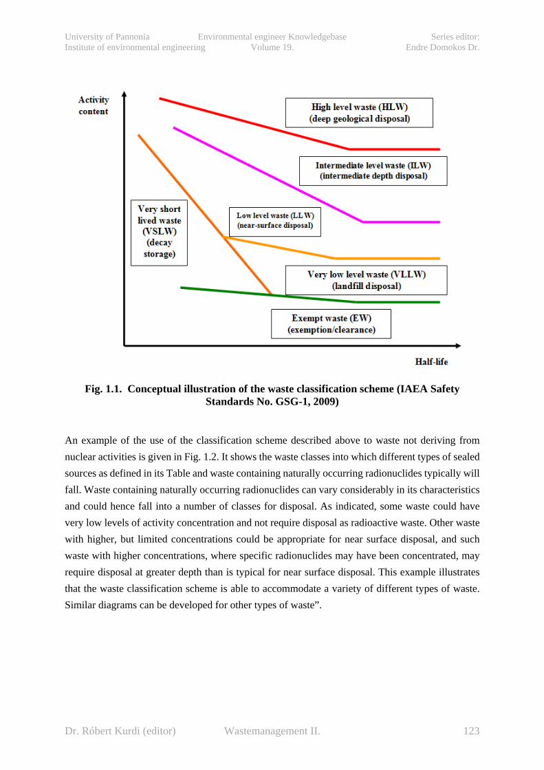
University of Pannonia Environmental engineer Knowledgebase Series editor: Institute of environmental engineering Volume 19. Endre Domokos Dr.
Fig. 1.1. Conceptual illustration of the waste classification scheme (IAEA Safety Standards No. GSG-1, 2009)
An example of the use of the classification scheme described above to waste not deriving from nuclear activities is given in Fig. 1.2. It shows the waste classes into which different types of sealed sources as defined in its Table and waste containing naturally occurring radionuclides typically will fall. Waste containing naturally occurring radionuclides can vary considerably in its characteristics and could hence fall into a number of classes for disposal. As indicated, some waste could have very low levels of activity concentration and not require disposal as radioactive waste. Other waste with higher, but limited concentrations could be appropriate for near surface disposal, and such waste with higher concentrations, where specific radionuclides may have been concentrated, may require disposal at greater depth than is typical for near surface disposal. This example illustrates that the waste classification scheme is able to accommodate a variety of different types of waste. Similar diagrams can be developed for other types of waste”.
Dr. Róbert Kurdi (editor) Wastemanagement II. 123

University of Pannonia Environmental engineer Knowledgebase Series editor: Institute of environmental engineering Volume 19. Endre Domokos Dr.
Fig. 1.2. Example of the application of the waste classification scheme. (According to IAEA Safety Standards No. GSG-1, 2009) The numbers refer to examples of disused
sealed sources set out in the upper table. The Naturally Occuring Radioactive Materials in the earth’s crust called as NORM. (Just for comparison: the approximate order of range of radioactivity content of the world seas is: 1022 Bq; Hiroshima bomb emission
to the air: 1016 Bq; Chernobil disaster’s emmission to the air: 4x10¹⁸ Bq; All radwastes of the world’s NPPs of the last half century: 1021 Bq)
Dr. Róbert Kurdi (editor) Wastemanagement II. 124
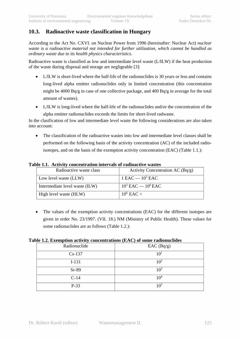
University of Pannonia Environmental engineer Knowledgebase Series editor: Institute of environmental engineering Volume 19. Endre Domokos Dr.
10.3. Radioactive waste classification in Hungary According to the Act No. CXVI. on Nuclear Power from 1996 (hereinafter: Nuclear Act) nuclear waste is a radioactive material not intended for further utilization, which cannot be handled as ordinary waste due to its health physics characteristics.
Radioactive waste is classified as low and intermediate level waste (L/ILW) if the heat production of the waste during disposal and storage are negligeable [3]:
• L/ILW is short-lived where the half-life of the radionuclides is 30 years or less and contains long-lived alpha emitter radionuclides only in limited concentration (this concentration might be 4000 Bq/g in case of one collective package, and 400 Bq/g in average for the total amount of wastes).
• L/ILW is long-lived where the half-life of the radionuclides and/or the concentration of the alpha emitter radionuclides exceeds the limits for short-lived radwaste.
In the clasification of low and intermediate level waste the following considerations are also taken into account:
• The classification of the radioactive wastes into low and intermediate level classes shall be performed on the following basis of the activity concentration (AC) of the included radio-isotopes, and on the basis of the exemption activity concentration (EAC) (Table 1.1.):
Table 1.1. Activity concentration intervals of radioactive wastes Radioactive waste class Activity Concentration AC (Bq/g)
Low level waste (LLW) 1 EAC — 103 EAC
Intermediate level waste (ILW) 103 EAC — 106 EAC
High level waste (HLW) 106 EAC <
• The values of the exemption activity concentrations (EAC) for the different isotopes are given in order No. 23/1997. (VII. 18.) NM (Ministry of Public Health). These values for some radionuclides are as follows (Table 1.2.):
Table 1.2. Exemption activity concentrations (EAC) of some radionuclides Radionuclide EAC (Bq/g)
Cs-137 101
I-131 102
Sr-89 103
C-14 104
P-33 105
Dr. Róbert Kurdi (editor) Wastemanagement II. 125

University of Pannonia Environmental engineer Knowledgebase Series editor: Institute of environmental engineering Volume 19. Endre Domokos Dr.
• If the radioactive waste contains several types of radioactive isotopes, then the classification shall be performed in accordance with the following (Table 1.3.):
Table 1.3. Activity concentration intervals of radwastes containing several types of radioactive isotopes
Radioactive waste class Comparison of the activity concentration
Low level waste (LLW) ∑i (ACi / EACi) ≤ 103
Intermediate level waste (ILW) 103 < ∑i (ACi / EACi) ≤ 106
Within the Hungarian regulation the standard MSZ 14344-1 re-issued in 2004 provides guidelines, by determination of those levels of the heat generation which shall be taken into account in course of storage (disposal). According to this in the case if the heat generation of the waste is less than 2 kW/m3, then it might be disposed as low and interim level radioactive waste.
10.4. The stored radwaste and spent fuel quantities in Hungary In Hungary, commercial utilisation of nuclear power started in 1983. All four nuclear power units are of the VVER 440/213 reactor type located at the Paks Nuclear Power Plant (NPP). Most of the radioactive waste in Hungary is generated by operation of the Paks NPP, with much smaller quantities being generated by other users of radioactive isotopes. Location of NPP and existing/planned radwaste disposal facilities are on Fig. 1.3.
Fig 1.3. Location of Paks NPP and existing/planned radwaste disposal facilities
Dr. Róbert Kurdi (editor) Wastemanagement II. 126

University of Pannonia Environmental engineer Knowledgebase Series editor: Institute of environmental engineering Volume 19. Endre Domokos Dr.
The fuel assemblies burnt in the reactor during the process of power generation are loaded for minimum 3 years to the cooling ponds, from where they are transferred to the Interim Spent Fuel Store (ISFS) for 50-year-long interim storage. (By 1998 there were 2331 spent fuel assemblies shipped back to the Soviet Union, and later to Russia, respectively. [3])
Table 1.4. indicates the quantities of the radioactive wastes disposed of temporarily and finally on Radioactive Waste Processing and Storage Facility (RWPS) operating in Püspökszilágy and Paks NPP sites, together with spent fuel assemblies, as well as the utilization of capacities of the storage facilities as of January 1, 2010.
Table 1.4. L/ILW, HLW and SF storage capacities and quantities in Hungary (2010)
10.4.1. Inventory and rate of generation of HLW from NPP operation HLW [3]: „is generated primarily by the Paks NPP, and only in relatively small quantities. At present, there is no decision on the back-end of the fuel cycle so the final form of HLW (spent fuel or the highly active residue arising from reprocessing) is not known. Spent fuel is stored for the time being in spent fuel ponds in the reactor buildings and in the Interim Spent Fuel Storage Facility (ISFS). The rate of generation of HLW from routine operations is 2.5-5 m3/year, which will result in a total of 130 m3 by the end of NPP operation. The amount of HLW from decommissioning of the Paks NPP is currently estimated to be about 250 m3, which is less than previous estimates”.
10.4.2. Inventory and rate of generation of L/ILW from NPP operation The amount of solid LLW/ILW [3]: „produced at the Paks NPP is now estimated at 190 m3 /year, after compaction. The rate of generation of liquid radioactive waste is about 270 m3 /year in total for the four reactor units. The total volume of LILW generated during the operation of Paks NPP will be about 22 000 m3. This amount does not consider the effect of the planned 20 year life time extension. The disposal capacity required for L/ILW from the decommissioning of the Paks NPP has recently been estimated to be about 17000 m3”.
Dr. Róbert Kurdi (editor) Wastemanagement II. 127

University of Pannonia Environmental engineer Knowledgebase Series editor: Institute of environmental engineering Volume 19. Endre Domokos Dr.
10.4.3. Rate of generation of LLW/ILW from small sources About 20-30 m3 of LLW/ILW [3]: „and 1 000 - 3 000 spent sealed radiation sources arise annually from small sources outside the nuclear power industry. Most of these radioactive wastes, including the spent sealed sources, are generated in medical, industrial and research applications. The two most widely used radionuclides are 60Co and 92Ir. They are used in medical and industrial radiography and give rise to significant inventories of activity”.
10.5. Waste management policiy in Hungary The spent fuel’s interim storage is carried out in storage modules in an ISFS at the Paks NPP. It is assured for 50 years and the capacity of the facility has been extended according to the actual demands. The liquid and solid LLW’s and ILW’s management is carried out by the operator of Paks NPP, which includes collection, processing, packaging, qualification and interim storage of these wastes on the NPP. The responsible body for the future transportation and disposal of these wastes is the Public Agency for Radioactive Waste Management (PURAM), which is also responsible for preparing the Paks NPP for decommissioning and for performing all related activities after plant shutdown, including dismantling, site restoration and waste disposal. All these activities are financed by the Central Nuclear Financial Fund (CNFF) according to the relevant regulations.
Dr. Róbert Kurdi (editor) Wastemanagement II. 128

University of Pannonia Environmental engineer Knowledgebase Series editor: Institute of environmental engineering Volume 19. Endre Domokos Dr.
11. Management principles and technical fundamentals for geological disposal of radioactive wastes (István Szűcs)
11.1. International principles of radioactive waste management In most of the countries regulation of radioactive waste managenent and final disposal are legalized on the basis of the directives of international radiation protection and safety. There are being developed the pillars of a standard system for radioactive waste management coordinated by the IAEA. International safety standards provide support for Member States in meeting their obligations under general principles of international law, such as those relating to environmental protection. International safety standards also promote and assure confidence in safety and facilitate international commerce and trade.
With a view to ensuring the protection of people and the environment from harmful effects of ionizing radiation, the IAEA safety standards establish fundamental safety principles, requirements and measures to control the radiation exposure of people and the release of radioactive material to the environment, to restrict the likelihood of events that might lead to a loss of control over a nuclear reactor core, nuclear chain reaction, radioactive source or any other source of radiation, and to mitigate the consequences of such events if they were to occur.
Safety standards of the IAEA reflect an international consensus on what constitutes a high level of safety for protecting people and the environment from harmful effects of ionizing radiation. They are issued in the IAEA Safety Standards Series, which has the following three categories:
• Safety Fundamentals present the fundamental safety objective and principles of protection and safety, and provide the basis for the safety requirements.
• Safety Requirements ― governed by the objective and principles of the Safety Fundamentals ― establish the requirements that must be met to ensure the protection of people and the environment, both now and in the future. The format and style of the requirements facilitate their use for the establishment, in a harmonized manner, of a national regulatory framework.
• Safety Guides provide recommendations and guidance on how to comply with the safety requirements, indicating an international consensus that it is necessary to take the measures recommended (or equivalent alternative measures).
The objective of radioactive waste management ― based on the nine principles (and set out in the Safety Fundamentals) summarized in the Table 2.1. ― is to deal with radioactive waste in a manner that protects human health and the environment now and in the future without imposing undue burdens on future generations.
In the system of dose limitation there are actually three features recommended [4] by International Commission on Radiological Protection (ICRP), namely justification, optimization, and dose limitation.
• Justification means that any proposed activity that may cause exposure to persons should yield a sufficient benefit to society to justify the risks incurred by the radiation exposure. This recommended feature is based on the assumption that any radiation exposure carries with it a certain level of risk that is proportional to the level of exposure, no matter how
Dr. Róbert Kurdi (editor) Wastemanagement II. 129
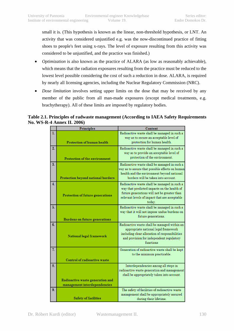
University of Pannonia Environmental engineer Knowledgebase Series editor: Institute of environmental engineering Volume 19. Endre Domokos Dr.
small it is. (This hypothesis is known as the linear, non-threshold hypothesis, or LNT. An activity that was considered unjustified e.g. was the now-discontinued practice of fitting shoes to people's feet using x-rays. The level of exposure resulting from this activity was considered to be unjustified, and the practice was finished.)
• Optimization is also known as the practice of ALARA (as low as reasonably achievable), which means that the radiation exposures resulting from the practice must be reduced to the lowest level possible considering the cost of such a reduction in dose. ALARA, is required by nearly all licensing agencies, including the Nuclear Regulatory Commission (NRC).
• Dose limitation involves setting upper limits on the dose that may be received by any member of the public from all man-made exposures (except medical treatments, e.g. brachytherapy). All of these limits are imposed by regulatory bodies.
Table 2.1. Principles of radwaste management (According to IAEA Safety Requirements No. WS-R-4 Annex II. 2006)
Dr. Róbert Kurdi (editor) Wastemanagement II. 130

University of Pannonia Environmental engineer Knowledgebase Series editor: Institute of environmental engineering Volume 19. Endre Domokos Dr.
11.2. General approaches to radioactive waste management The welfare and development of modern societies strongly depend upon the contribution of technology and industrial processes, such as the generation and consumption of electricity. All of the elements of these processes are associated with the production of wastes, some of which are unavoidable, hazardous and unrecyclable as well. To ensure effective protection of humans and the environment most of all kind of such wastes require careful management. If these wastes contain toxic chemical elements or long-lived radioactive isotopes, the timescales over which such protection is required can extend well beyond the lifespans of current or forthcoming generations, i.e., many thousands of years. Therefore we have to face with an ethical imperative to care about future generations and to act in such a way as to preserve, as much as possible, their options to enjoy and benefit from the Earth’s resources and environment. Such a concern for the protection of human health and the environment in a developing world has been illustrated by the concept of "sustainable development" put forward by the World Commission on Environment and Development, "the Brundtland Commission", in 1987 [5]. This ― principally an ethical ― concept was defined as "satisfying the needs of the present, without compromising the ability of future generations to meet their own needs".
The further considerations and concerns of the concept of "sustainable development" led to a set of principles to be used as a basic guide in making ethical choices about radwaste management strategy (according to the OECD NEA, 1995) [5]”:
• the liabilities of waste management of new projects should be considered;
• those who generate the wastes should take responsibility, and provide the resources, for the management of these materials in a way which will not impose undue burdens on future generations;
• wastes should be managed in a way that secures an acceptable level of protection for human health and the environment, and affords to future generations at least the level of safety which is acceptable today; there seems to be no ethical basis for discounting future health and environmental damage risks;
• a waste management strategy should not be based on a presumption of a stable societal structure for the indefinite future, nor of technological advance; rather it should aim at bequeathing a passively safe situation which places no reliance on active institutional controls”.
In technical and economic terms the exact measures preferred to achieve isolation of the different types of waste depend upon their physical and chemical characteristics. It is characteristic of radioactive wastes (with the exception of the natural radioactive residues from uranium mining), that their volume is relatively very small. The half-lives of the radioactive substances in some wastes from power stations, medical applications and research are short enough so effective isolation for their decay period is achievable by deposition in supervised near-surface vaults, or by other means of storage.
The schematic concept of the advised repository options for final disposal of different radioactive wastes types (on Fig. 2.1.) are generally accepted both by specialists and decision makers. The concept of geologic disposal of long-lived radioactive waste involves deep underground repositories that ensure security, i.e. resistance to malicious or accidental disturbance, and containment of the waste over very long times. Most of the nations where long-lived radioactive waste is an issue have set up radioactive waste management programmes that ultimately aim to emplace this waste in a geologic disposal facility. Fig 2.2. illustrates the places and depths of Underground Research
Dr. Róbert Kurdi (editor) Wastemanagement II. 131
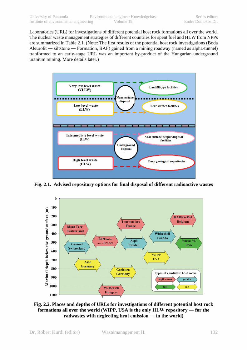
University of Pannonia Environmental engineer Knowledgebase Series editor: Institute of environmental engineering Volume 19. Endre Domokos Dr.
Laboratories (URL) for investigations of different potential host rock formations all over the world. The nuclear waste management strategies of different countries for spent fuel and HLW from NPPs are summarized in Table 2.1. (Note: The first results of the potential host rock investigations (Boda Aleurolit ― siltstone ― Formation, BAF) gained from a mining roadway (named as alpha-tunnel) tranformed to an early-stage URL was an important by-product of the Hungarian underground uranium mining. More details later.)
Fig. 2.1. Advised repository options for final disposal of different radioactive wastes
Fig. 2.2. Places and depths of URLs for investigations of different potential host rock
formations all over the world (WIPP, USA is the only HLW repository ― for the radwastes with neglecting heat emission ― in the world)
Dr. Róbert Kurdi (editor) Wastemanagement II. 132
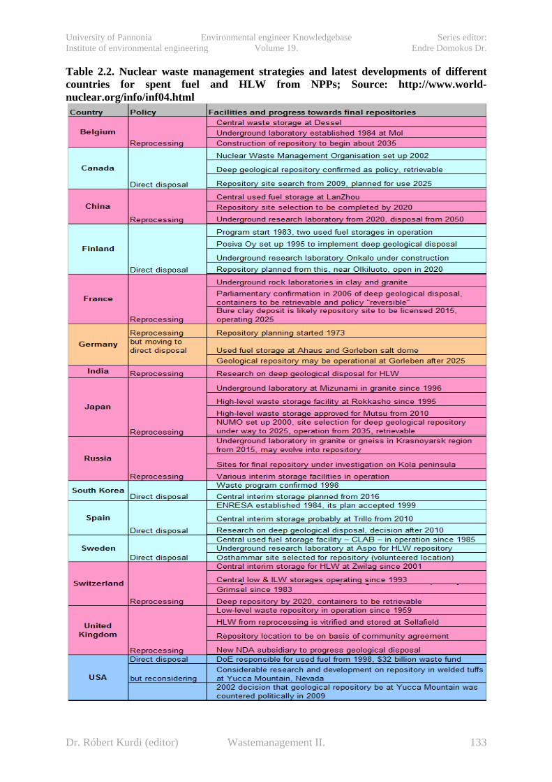
University of Pannonia Environmental engineer Knowledgebase Series editor: Institute of environmental engineering Volume 19. Endre Domokos Dr.
Table 2.2. Nuclear waste management strategies and latest developments of different countries for spent fuel and HLW from NPPs; Source: http://www.world-nuclear.org/info/inf04.html
Dr. Róbert Kurdi (editor) Wastemanagement II. 133

University of Pannonia Environmental engineer Knowledgebase Series editor: Institute of environmental engineering Volume 19. Endre Domokos Dr.
11.3. Technical fundamentals for geological disposal Analyzing the knowledge basis- and focusing on the technical fundamentals of the geological disposal of radioactive waste the IAEA Technical Reports Series No. 413A (Scientific and Technical Basis for Geological Disposal of Radioactive Wastes) [6] summarize the present state of:
a) Geological disposal concept and the different requirements and functions to be challenged and fulfilled during its lifetime.
b) Important processes of retarding and storing of radionuclides.
c) Central role of safety case and use of safety/performance assessments systems during decision making processes of preparation and construction of facilities.
d) Reasonably achivable scientific and technical knowledge serving safety reasons in connection with siting and disposal concept.
Although a large part of existing knowledge is generic in nature and is derived from the earth sciences and from mining engineering work, much specific knowledge has been derived from the characterization of potential repository sites and from studies in underground research laboratories (URL).
According to the summary of Organization for Economic Co-operation and Development (OECD) and Nuclear Energy Agency (NEA) in their publication [7] „Progress towards geological disposal of radioactive waste: Where do we stand?” (1999): Since the geologic disposal concept was proposed, research and development efforts world-wide have increased understanding of how underground disposal facilities will function over very long periods of time, and have enhanced confidence in the ultimate safety of the concept. While significant progress has been made towards development of these facilities, there have also been delays and setbacks primarily due to failure of the waste management experts and institutions to win sufficient public or political support. In recent years, as the concept itself is nearing implementation in several countries, support is being voiced in some quarters for postponement of disposal and for more review of alternative waste management options. On the other hand, reflections in international groups of experts have repeatedly confirmed the conviction that geologic disposal is ethical, environmentally sound and safe, and other management options are, at most, complementary to geologic disposal rather than complete, long-term alternatives.
The idea of removing long-lived radioactive waste from the human environment by placing it in deep underground repositories – geologic disposal – was proposed over more than half century ago. According to the type of waste, details vary from country to country. The geologic disposal concept involves treating the waste in order to achieve a suitable physical and chemical form, packaging it inside long-lived engineered barriers emplaced deep underground, and sealing these facilities. In these underground surroundings conditions remain stable over the long periods needed to allow the radioactivity to decay.
11.3.1. The concept and definition of geologial disposal Radioactive waste disposals in a deep stable geological environment is intended to provide sufficient isolation, both from human activity and from dynamic natural processes, that eventual releases of radionuclides will be in such low concentrations that they do not endanger the natural environment and human health. Acording to the definition geological disposal is considered to be a combination of conditioned and packaged solid wastes and other engineered barriers within an
Dr. Róbert Kurdi (editor) Wastemanagement II. 134

University of Pannonia Environmental engineer Knowledgebase Series editor: Institute of environmental engineering Volume 19. Endre Domokos Dr.
excavated or drilled repository in a stable geological environment located at a depth of some hundreds of metres.
The host rock (can be defined as a geological formation in which the waste is emplaced), generally constitutes the most important isolation barrier. Different barriers act together, initially to contain the radionuclides allowing them to decay, and then to limit their releases to the accessible environment.
A multibarrier system is generally known as a combination of engineered and geological barriers. The multibarrier systems are fully effective only after closure of the repository. The repository closure is defined as the series of operations required to emplace all barriers planned by the repository design and to backfill underground openings and seal any connections between the disposal zone and the surface or the surrounding formations.
The theoretical basis of geological disposal is that the combination of natural and engineered barriers should contain the short lived, highly active radionuclide content of the wastes completely, i.e. until their radioactivity has decayed to insignificant levels. The range of this period is generally of the order of a few hundreds to a few thousands of years.
Terms of geological disposal and underground investigations are used in accordance with the following IAEA definitions [6]:
• Geological disposal: Emplacement of wastes in an appropriate facility at a depth of at least several hundreds metres without the intention of retrieval. While geological disposal is generally associated with the disposal of solid long lived radioactive wastes, some Member States plan to place all types of radioactive waste in geological repositories.
• Geological repository: A facility for radioactive waste disposal located underground (usually several hundred metres below the surface) in a stable host rock to provide long term isolation of radionuclides from the accessible environment (biosphere).
• Underground repository: Generic term no longer used formally in IAEA documents in relation to the disposal of radioactive wastes. The term refers to any disposal facility located in a geological environment at a depth greater than some tens of metres. It includes repositories for LILW in engineered rock cavities, boreholes and other underground facilities for the disposal of hazardous wastes.
• Underground research laboratory: An underground research laboratory (URL) or facility is any underground facility (purpose built or existing) used to carry out experiments and other in situ R&D work needed in the development of a geological disposal system.
Any geological disposal and underground systems defined above, after closure, (according to the IAEA Technical Reports Series No. 413A [6]): can be seen to have different functions at different times in the future”:
• Isolation from near surface influences: by removing the wastes from the near surface environment they are protected from the active outside impacts.
• Biosphere protection: the biosphere is protected and shielded from the radioactivity of the wastes, which is at its peak in the first few hundred years after disposal.
Dr. Róbert Kurdi (editor) Wastemanagement II. 135
University of Pannonia Environmental engineer Knowledgebase Series editor: Institute of environmental engineering Volume 19. Endre Domokos Dr.
• Human acccess isolation: deep disposal of wastes makes it less likely that future human activities will result in exposure to radioactivity, either indirectly (by some means of mobilizing components of the waste) or directly (by intended human intrusion).
• Containment at an early phase : substantially complete containment of short lived radionuclides for some hundreds or thousands of years, largely within the engineered barriers of the repository systems.
• Releas limitation: delaying and limiting the rate and the consequent concentrations in which radionuclides will be released from the progressively degrading engineered barrier system (EBS) into the geological environment and eventually transported to the biosphere, achieved by a combination of physical and chemical mechanisms. This among other functions, may limit the access and flux of groundwater to the wastes and from the repository to the biosphere, and may limit the solubility of radionuclides, or sorb or precipitate them reversibly or permanently onto surfaces in the host rocks and the EBS. The process of radioactive decay, in addition, progressively reduces the amount of radionuclides present in the disposal system.
• Dilution and dispersion: the flux of long lived radionuclides through the rocks of the geological barriers implies three dimensional dispersion. Besides it may take place in widely different groundwater environments. At some specific proposed repository sites and in some concepts, releases would encounter major bodies of groundwater at depth or closer to the surface, or similar large bodies of surface water. It may result in an additional function, i.e. an overall dilution of released radionuclides such that concentrations on initial return to the biosphere are decreased”.
Dr. Róbert Kurdi (editor) Wastemanagement II. 136

University of Pannonia Environmental engineer Knowledgebase Series editor: Institute of environmental engineering Volume 19. Endre Domokos Dr.
12. Case history files of Hungarian radwaste management and research (István Szűcs)
12.1. Financial and managerial background According to the Hungarian Nuclear Act the performance of the tasks (in connection with the responsibility for dealing with tasks related to the final disposal of the radioactive wastes, interim storage and final disposal of spent nuclear fuel, furthermore with the issues related to the decommissioning of the nuclear facility) will be financed from the Central Nuclear Financial Fund (hereinafter: CNFF or Fund) existing as separated state financial fund. The manager of the Fund is the Hungarian Atomic Energy Authority (hereinafter HAEA) supervised by a nominated minister responsible for the Fund [8].
HAEA has been entrusted to establish the Public Utility for Radioactive Waste Management (hereinafter PURAM) for co-ordinating executive tasks. It is required within the scope of the planning and reporting activities of PURAM to prepare mid and long term plans (which are served as one of the a bases of the facts of this chapter) the for the activities to be financed from the Fund and of the income sources of the Fund as well as the annual review of them making possible to enforce the basic principle of having the generation using the nuclear power to pay for the costs arising in the future and related to this utilization without leaving unjustified burdens to the next generations.
The mid and long term plan deals separately with the issues related to the spent fuel management generated in the nuclear facilities operated by institutions financed by State Budget (training reactor of the Budapest University of Technical and Economical Sciences, Institute of Nuclear Technology [BME NTI] and the research reactor in the Atomic Energy Research Institute of the Central Physical Research Institute of the Hungarian Academy of Sciences [KFKI AEKI]) and the decommissioning of these facilities.
12.2. Milestones of the low and intermediate level radwaste management Radioactive wastes appeared simultaneously with the introduction of use of the isotope technology in Hungary. The first temporary storage of these wastes were initially on site of the Central Research Institute of Physics and by 1960 an experimental isotope repository was constructed in Solymár. The capacity of the experimental repository was shortly exhausted so a new facility (a repository of a near surface pool and tube pit formation) was completed in Püspökszilágy (Radioactive Waste Processing and Storage Facility; hereinafter: RWPS) by 1976, with capacity of 3540 m3 [8].
From 1990 to 1991 the transportation of the low and interim level radioactive wastes to the RWPS was suspended due to public resistance. At the same time the storage capacity of the Püspökszilágy RWPS was expanded to 5040 m3 . After stop of the public protest further low and interim level radioactive wastes were transferred to Püspökszilágy in period between 1992 and 1996, so altogether there is some 1580 m3 nuclear power plant origin waste was disposed in approximately 2500 m3 of storage capacity [8].
Since such an expansion of the Püspökszilágy facility that would satisfy the total need of the NPP was impossible, beginning from 1993 an Interdepartmental Target Project (later on National Project) has been launched. The whole country has been screened on the basis of the professional literature data, and later on in the promising areas, where the public supported it as well, preliminary site explorations were carried out in order to identify the geological objects suitable for surface and near surface repository.
Dr. Róbert Kurdi (editor) Wastemanagement II. 137
University of Pannonia Environmental engineer Knowledgebase Series editor: Institute of environmental engineering Volume 19. Endre Domokos Dr.
In 1996 the final document of the geological, safety technical and economical investigations proposed to carry out further explorations in the vicinity of Üveghuta for near surface disposal in granite, keeping in reserve the sites that seemed to be suitable for construction of surface repositories (Diósberény, Udvari).
At the end of 1998, in its final report on the geological investigations carried out in 1997-1998 the Hungarian State Geological Institute (MÁFI) made a recommendation to start the detailed geological and site characterizing works founding the licensing procedure and the construction in the Üveghuta research area.
At this point the program got into the focus of the professional and political debates. Due to it the experts of the International Atomic Energy Agency, upon request of HAEC have reviewed the activities carried out within the framework of the program, and agreeing with the results gained by that time they have suggested the continuation the explorations.
Based on the facts above, in 2001 started a four-year exploration program. Preparations of the contracts referring to the explorations were conducted within the framework of a public procurement process. In December 2001, the BÁTATOM Ltd. was established aiming to implement the program, by holding together the most excellent institutions in Hungary (ETV – Erőterv Ltd., Mecsekérc Environment Protection Ltd., Golder Associates Hungary Ltd.) and with the support of the Hungarian State Geological Institute, as subcontractor. During year 2002 the BÁTATOM Ltd. along with preparatory works necessary for the investigations has prepared the geological research plan. On the basis of the licensed plan there was a final report prepared on the performed geological investigations at the end of 2003, the main statements of which were the followings: „The Bátaapáti (Üveghuta) site complies with all the requirements set forth in the order, and thus, from geological point of view it is suitable for final disposal of low and intermediate level radioactive wastes.” This document was evaluated by the competent geological authority, the South-Transdanubian Regional Office of the Hungarian Geological Service, and has accepted it [8].
The underground researches were started in February 2005 by deepening of the inclining shafts. Two further important events took place in 2005. Upon initiative of municipality of Bátaapáti an opinion expressing public poll was held in the town. Along with high (75%) participation nearly 90.7% of the people voting agreed with construction of a low and intermediate level radwaste repository in Bátaapáti. On November 21, 2005 the Hungarian Parliament, based on Paragraph (2) of Article 7 of the Nuclear Act granted a preliminary, principal approval for beginning of preparatory activities for low and intermediate level radwaste repository on the territory which has been already earlier qualified as suitable from geological point of view. The resolution of the Parliament was supported by overwhelming majority of the MPs present (339 persons, 96,6%). An important event of year 2006 was the acceleration of the licensing procedures related to the Bátaapáti investment. Based on its rights provided in Act No. LIII from 2006, the Government, by means of issuing its Governmental Decree 275/2006 declared that the waste repository being under construction in Bátaapáti is an investment of enhanced importance falling under the power of the above mentioned Act [8].
By the end of 2009 the Eastern inclining shaft, the Western one, and six connection tunnels were constructed (with other preparatory tunnels for waste chambers, alltogether: 5100 m). Simultaneously with the mining activities the underground researches were continued, and the relevant final reports were prepared.
12.3. Milestones and background of spent fuel management Following commissioning of Paks Nuclear Power Plant the burning of the nuclear fuel has
started. Afterwards the spent fuel assemblies were discharged from the reactors to the next to the reactors cooling pools.
Dr. Róbert Kurdi (editor) Wastemanagement II. 138
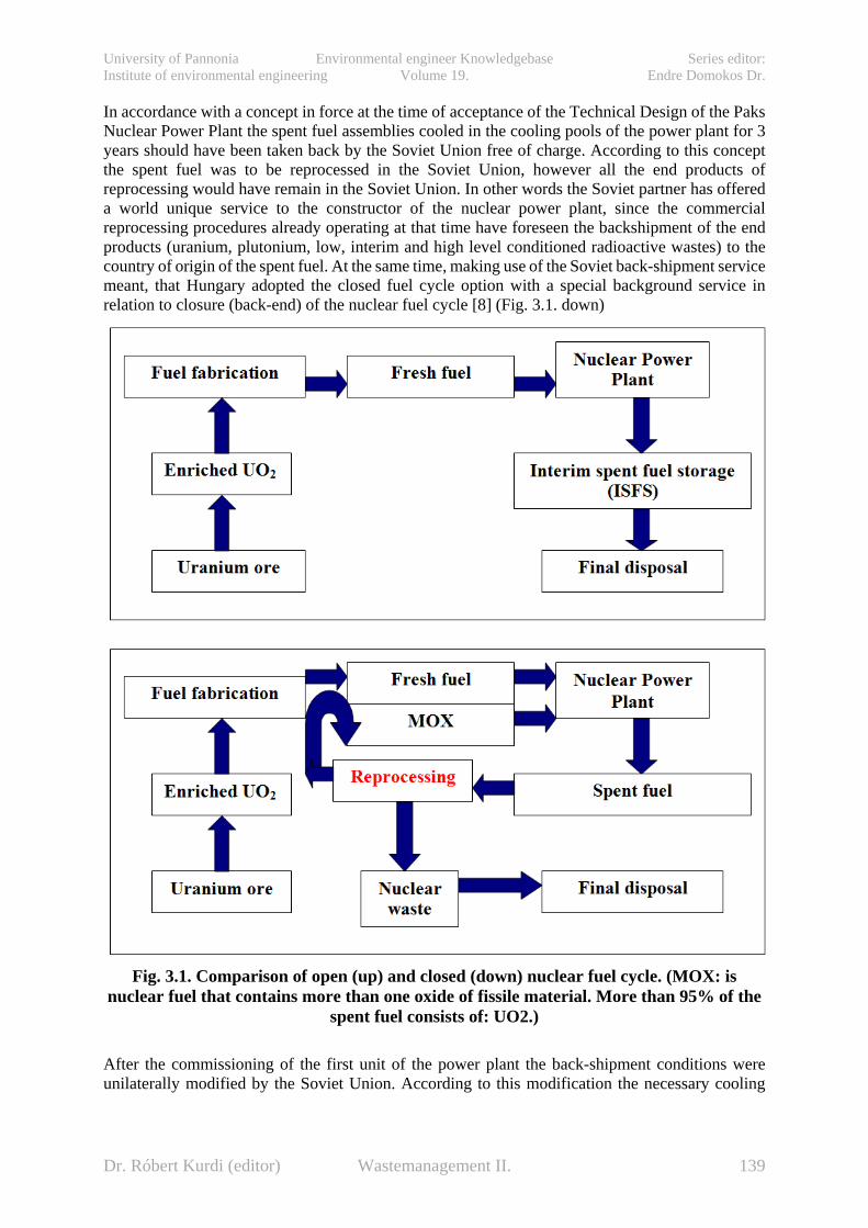
University of Pannonia Environmental engineer Knowledgebase Series editor: Institute of environmental engineering Volume 19. Endre Domokos Dr.
In accordance with a concept in force at the time of acceptance of the Technical Design of the Paks Nuclear Power Plant the spent fuel assemblies cooled in the cooling pools of the power plant for 3 years should have been taken back by the Soviet Union free of charge. According to this concept the spent fuel was to be reprocessed in the Soviet Union, however all the end products of reprocessing would have remain in the Soviet Union. In other words the Soviet partner has offered a world unique service to the constructor of the nuclear power plant, since the commercial reprocessing procedures already operating at that time have foreseen the backshipment of the end products (uranium, plutonium, low, interim and high level conditioned radioactive wastes) to the country of origin of the spent fuel. At the same time, making use of the Soviet back-shipment service meant, that Hungary adopted the closed fuel cycle option with a special background service in relation to closure (back-end) of the nuclear fuel cycle [8] (Fig. 3.1. down)
Fig. 3.1. Comparison of open (up) and closed (down) nuclear fuel cycle. (MOX: is
nuclear fuel that contains more than one oxide of fissile material. More than 95% of the spent fuel consists of: UO2.)
After the commissioning of the first unit of the power plant the back-shipment conditions were unilaterally modified by the Soviet Union. According to this modification the necessary cooling
Dr. Róbert Kurdi (editor) Wastemanagement II. 139
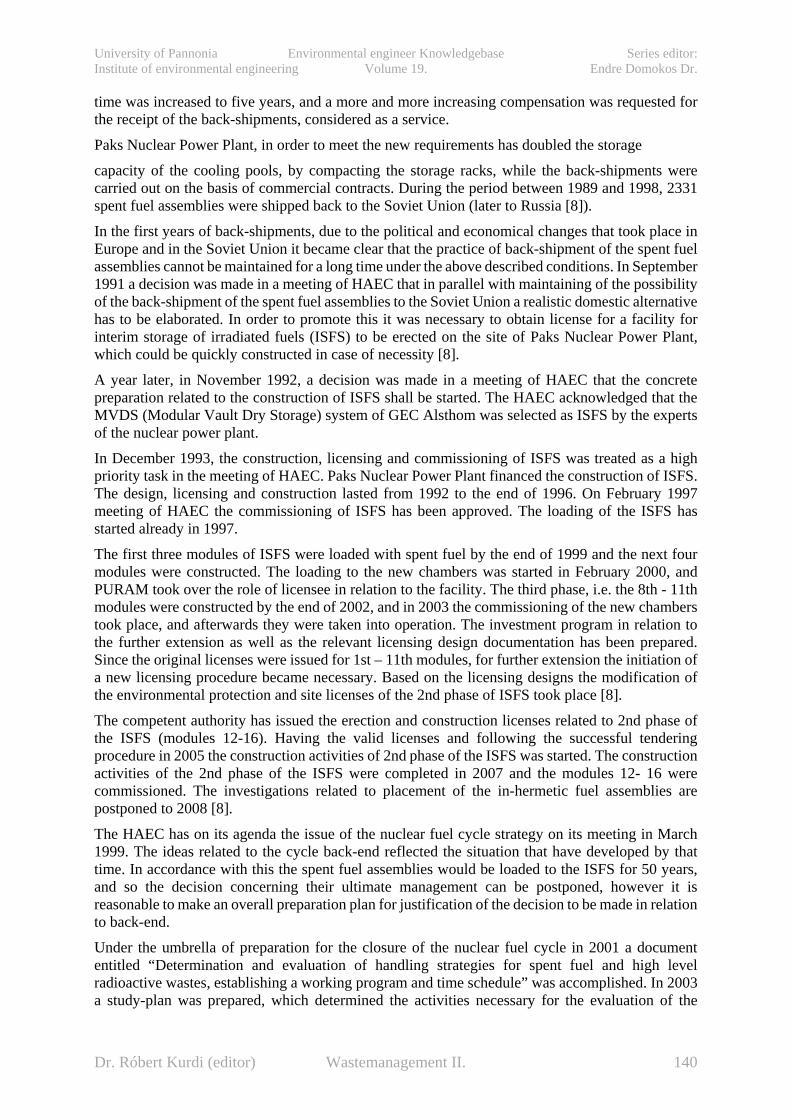
University of Pannonia Environmental engineer Knowledgebase Series editor: Institute of environmental engineering Volume 19. Endre Domokos Dr.
time was increased to five years, and a more and more increasing compensation was requested for the receipt of the back-shipments, considered as a service.
Paks Nuclear Power Plant, in order to meet the new requirements has doubled the storage
capacity of the cooling pools, by compacting the storage racks, while the back-shipments were carried out on the basis of commercial contracts. During the period between 1989 and 1998, 2331 spent fuel assemblies were shipped back to the Soviet Union (later to Russia [8]).
In the first years of back-shipments, due to the political and economical changes that took place in Europe and in the Soviet Union it became clear that the practice of back-shipment of the spent fuel assemblies cannot be maintained for a long time under the above described conditions. In September 1991 a decision was made in a meeting of HAEC that in parallel with maintaining of the possibility of the back-shipment of the spent fuel assemblies to the Soviet Union a realistic domestic alternative has to be elaborated. In order to promote this it was necessary to obtain license for a facility for interim storage of irradiated fuels (ISFS) to be erected on the site of Paks Nuclear Power Plant, which could be quickly constructed in case of necessity [8].
A year later, in November 1992, a decision was made in a meeting of HAEC that the concrete preparation related to the construction of ISFS shall be started. The HAEC acknowledged that the MVDS (Modular Vault Dry Storage) system of GEC Alsthom was selected as ISFS by the experts of the nuclear power plant.
In December 1993, the construction, licensing and commissioning of ISFS was treated as a high priority task in the meeting of HAEC. Paks Nuclear Power Plant financed the construction of ISFS. The design, licensing and construction lasted from 1992 to the end of 1996. On February 1997 meeting of HAEC the commissioning of ISFS has been approved. The loading of the ISFS has started already in 1997.
The first three modules of ISFS were loaded with spent fuel by the end of 1999 and the next four modules were constructed. The loading to the new chambers was started in February 2000, and PURAM took over the role of licensee in relation to the facility. The third phase, i.e. the 8th - 11th modules were constructed by the end of 2002, and in 2003 the commissioning of the new chambers took place, and afterwards they were taken into operation. The investment program in relation to the further extension as well as the relevant licensing design documentation has been prepared. Since the original licenses were issued for 1st – 11th modules, for further extension the initiation of a new licensing procedure became necessary. Based on the licensing designs the modification of the environmental protection and site licenses of the 2nd phase of ISFS took place [8].
The competent authority has issued the erection and construction licenses related to 2nd phase of the ISFS (modules 12-16). Having the valid licenses and following the successful tendering procedure in 2005 the construction activities of 2nd phase of the ISFS was started. The construction activities of the 2nd phase of the ISFS were completed in 2007 and the modules 12- 16 were commissioned. The investigations related to placement of the in-hermetic fuel assemblies are postponed to 2008 [8].
The HAEC has on its agenda the issue of the nuclear fuel cycle strategy on its meeting in March 1999. The ideas related to the cycle back-end reflected the situation that have developed by that time. In accordance with this the spent fuel assemblies would be loaded to the ISFS for 50 years, and so the decision concerning their ultimate management can be postponed, however it is reasonable to make an overall preparation plan for justification of the decision to be made in relation to back-end.
Under the umbrella of preparation for the closure of the nuclear fuel cycle in 2001 a document entitled “Determination and evaluation of handling strategies for spent fuel and high level radioactive wastes, establishing a working program and time schedule” was accomplished. In 2003 a study-plan was prepared, which determined the activities necessary for the evaluation of the
Dr. Róbert Kurdi (editor) Wastemanagement II. 140

University of Pannonia Environmental engineer Knowledgebase Series editor: Institute of environmental engineering Volume 19. Endre Domokos Dr.
potential strategies. [8] On the basis of this the development of the strategy itself will be the task of the coming years.
In 2003 the representatives of the Hungarian and Russian Governments have re-started the negotiations aimed for back-shipment of the spent nuclear fuel to Russia, which were oriented tothe reconsideration of the former inter-governmental protocol, which has existed between the two countries. Finally, such an agreement was concluded on April 2004, which might constitute a legal basis for Hungary for back-shipment of the spent fuel assemblies to Russia even after our joining to the European Union [8].
12.4. Milestones and background of HLW management and research The commissioning of Paks Nuclear Power Plant has created a new situation since it became evident that the operation and decommissioning of the nuclear power plant will significantly contribute to the source term of the Hungarian high level radioactive wastes. It has been obvious from the very beginning that all the problems in the management of that type of waste will have to be solved by Hungary on its own.
The National Project launched in 1993 (beyond dealing with solution of the safe disposal of the low and interim level radioactive wastes), in relation to high level radioactive wastes has been expanded upon initiative of IKIM (Ministry of Industry, Trade and Tourism) with the task of continuation of the earlier started investigations of the Boda Aleurolit Formation (BAF) (or in international context sometimes abbreviated as BCF Boda Claystone Formation). This activity has been completed in 1995, and so an independent program has been launched for solution of disposal of the Hungarian high level and long life-time radioactive wastes. This program has already outlined long term ideas, however it was focusing on the in-situ investigations due in 1996-98, which was carried out by the Canadian AECL and the Mecsek Ore Mining Company in the area of BAF at 1100 m depth, with the purpose of detailed investigation of the formation [9]. A time limitation for the three-year-program was that the closure of the mine was forecasted for 1998 that time, so it was the time period during which the existing infrastructure could be economically utilized.
On this basis the explorations were completed in the end of 1998 in a documented form. According to the final report there were no such circumstances revealed that could prevent the construction of a facility serving as repository for long life-time and high level radioactive wastein the BAF. Upon effect of the results of the final report a recommendation was made for construction of an underground research base, for qualification of BAF and for further researches. The minister of economy made the relevant decision in 1999, rejecting the proposal. At the same time decision was made on closure of the uranium mine in accordance with the original plan.
The activities related to construction of the high level radwaste repository were reconsidered and a need arose for investigation of other Hungarian site alternatives as well. This aim was supported by the nationwide screening completed in October 2000. Within the framework of this a criteria system was elaborated – in order to support the evaluation of the sites – , followed by mapping and evaluation on the basis of the criteria system the areas suitable for final disposal of the high level radioactive wastes. On the basis of the investigation results among the host rock formations, which could be potentially taken into account in Hungary, considering its favorable geological parameters and the reliability of the known characteristics (parameters) involved into the evaluation Boda Aleurolit in the Mecsek Mountains proved to be an outstanding formation and in the rank of formations put to the first place [9].
On the basis of this promising result PURAM has prepared a research program for investigation of a site suitable for disposal of the Hungarian high level and long-life radioactive wastes started in 2003 aiming on selection of the location for a new underground research laboratory.
Dr. Róbert Kurdi (editor) Wastemanagement II. 141

University of Pannonia Environmental engineer Knowledgebase Series editor: Institute of environmental engineering Volume 19. Endre Domokos Dr.
Within the framework of this program in 2004 geological and geophysical mapping, shallow and deep boring researches took place as well as theoretical-methodological developments. Also in 2004 was prepared the concept plan (TS(R)/6/25) related to disposal of spent nuclear fuel of the nuclear power plant and of other origin fuel assemblies as well of high level radioactive wastes. From 2005 due to decreased financial resources the volume of the executed works proportionally decreased as well. The available financial resources in 2006-2007 provided possibility only for continuous operation of environmental monitoring. As a consequence of all this by now there is an almost a decade delay compared to the original research plan.
12.5. Investigation of BCF as a potential host formation for HLW and spent fuel
The theoretical suitability of BCF was already suggested in the early 80s on the basis of the results and data of detailed geological exploration connected with four decades of uranium ore prospecting, drilling, exploration and mining. Therefore the quantity of information – concerning the geological environment of the potential host rock formation, as well its geological environment, the Western Mecsek Mountains, – exceeded by orders the level of knowledge about any other potential geological formation in Hungary (Distribution of uranium research boreholes: Fig. 3.2. left side; Geological map: Fig. 3.3.).
Between 1989 and 1992 MÉV (Mecseki Ércbányászati Vállalat = Mecsek Ore Mining Enterprise), accomplished a self-financed project for the investigation of disposal possibility of LLW and ILW and/or hazardous toxic waste.
On the basis of the first promising results, the work was continued between 1993 and 1995 in the framework of a National Project considering the disposal aspects of HLW, originating from Paks NPP. This was the so-called Alfa-project (Fig. 3.2. right side). This provided a great progress in learning the characteristics of BAF. It should be highlighted that in the summer of 1994 the underground excavation of the formation was completed using the favorably located tunnels of the mine at the average depth of 1050 m. It ensured an exploration capability requiring hundreds of million USD and one-two decades of investment in countries developing this exploration capability right from the surface. However, this object served only explorational purposes, since the presence of the cavity system of the uranium ore mine meaned an unacceptable risk for the final disposal. Therefore the plan was to find a place in BCF, farther away from the zone of the cavity system for the final diposal, in a favorable depth range.
The most important technical and methodological knowledge background for the Hungarian project was provided by AECL (Atomic Energy of Canada Ltd.) through the documentation transmitted during the Alfa-project and by compilation of the concept level plans of short term exploration. Just before the completion of this project, in December 1994 a governmental decree declaring the abolition of Hungarian uranium ore mining was issued. According to this the exploration of BCF was to be continued until the termination of ore production activities. On the basis of this governmental decision a conceptual plan was elaborated for three year’s exploration period (the so-called Short Term Program; STP), with the participation of AECL.
Dr. Róbert Kurdi (editor) Wastemanagement II. 142
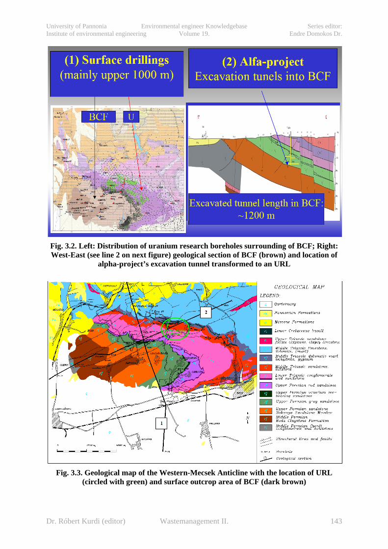
University of Pannonia Environmental engineer Knowledgebase Series editor: Institute of environmental engineering Volume 19. Endre Domokos Dr.
Fig. 3.2. Left: Distribution of uranium research boreholes surrounding of BCF; Right: West-East (see line 2 on next figure) geological section of BCF (brown) and location of
alpha-project’s excavation tunnel transformed to an URL
Fig. 3.3. Geological map of the Western-Mecsek Anticline with the location of URL (circled with green) and surface outcrop area of BCF (dark brown)
Dr. Róbert Kurdi (editor) Wastemanagement II. 143

University of Pannonia Environmental engineer Knowledgebase Series editor: Institute of environmental engineering Volume 19. Endre Domokos Dr.
The company leading all these activities was MECSEKÉRC, the legal successor of MÉV with the following short history: The MÉV (Mecseki Ércbányászati Vállalat = Mecsek Ore Mining Enterprise) was beginning its activity on January 1st 1964, when it was established by the change of the name of Pécsi Uránércbánya Vállalat (=Uranium Ore Mine Enterprise of Pécs), active since 1956. The company had 5 mine plants (numbered I. to V.) in total but not all at the same time. Since 1989 the activity was decreasing because of governmental restrictions, explained with economic reasons (low price of the ore concentrate, etc.). The mines were separated in a company named Mecsekurán Ltd. in 1992 and finished their activity at the end of 1997. The mother company was transformed in 1998 under the name MECSEKÉRC Környezetvédelmi és Ércbányászati Rt. (= MECSEK ORE Environmental Protecting and Ore Mining Co. Inc.), which finally named as MECSEKÉRC Környezetvédelmi Zrt. – this means MECSEKÉRC Environmental Exclusively Acting Corporation – in 2006.
12.5.1. Short Term Programme (STP) of BCF In 1994 under a Canadian – Hungarian intergovernmental agreement and the Paks NPP (Paks Nuclear Power Plant Inc.) – AECL contracts a study was compiled with the involvement of many Hungarian experts. It records and systemizes the activities and information required for the overall geological qualification of a formation potentially suitable for HLW disposal. According to this report, if each of the conditions is met, the completion of the listed tasks would require appr. 10-15 years. This is the so-called Long Term Programme (LTP).
The professional goals of the STP – for a three year (1995 – 1998) period, as the first phase of the LTP – could have been summarized [13]as follows:
• First of all those critical factors and parameters were examined, which – if the investigations would result as unfavorable – would have led to a questioning of the suitability of BCF (or to the qualification of BCF as „inadequate”).
• Because of the planned closing process of the uranium ore mines – within the framework of the restricted financial sources – all information should have been obtained, which could be reached exclusively by utilizing facilities in the mines.
The exploration plan contained four groups of investigations to carry out:
• In situ investigations and geotechnical experiments in underground research facilities. To serve the planned examinations, the total length of tunnel in BAF documented in detail was 256 m. In the mines 1950 m of boreholes were drilled – with core drilling method – altogether (see: Fig. 3.4.).
• Surface geological and hydrogeological survey and investigations. – Within the 25 km2 surface outcrop area, beside mapping-sampling activities, 6 shallow boreholes were drilled in a total length of 400 m, and 446 artificial and natural exposures were fully documented. Other actvities: 2650 m of geoelectric profiling, the settling of a GPS system and of some surface monitoring elements.
• The general laboratory examination of water and rock samples from underground facilities and surface mapping, including isotope-transport parameter tests.
• Other tasks, differing from those as listed: collection and assessment of archive data, upload of elctronic database, development of GIS, data evaluation and interpretation.
Dr. Róbert Kurdi (editor) Wastemanagement II. 144

University of Pannonia Environmental engineer Knowledgebase Series editor: Institute of environmental engineering Volume 19. Endre Domokos Dr.
Resulting from the above mentioned targets and areas, within the exploration phase the following primary exploration tasks were in focus:
• investigation of primary isolating performance of the formation;
• acquisition of general geological knowledge useable in the overall qualification of the formation;
• investigation of geotechnical feasibility and the changes caused by mining activities activities ensuring the storage, manageability and large scale interpretability of information.
Fig. 3.4. Geological cross-section in the vertical plane of the Alpha-1 exploratory tunnel
(1000 m under the surface) The activities aiming at the qualification of BCF carried out in a very advantageous exploration situation due to the good geometry. The entire depth range between the surface outcrop and the deep level exploration tunnel can be examined simultaneously in its connection ensuring the acquisition of the maximum set of information in this way. In longer term the spatial variability of various parameters can be quantified. Through the application of different surface and drilling investigation methods the exploration was extendable towards the underlying rock of BCF.
The underground exploration facilities serving the investigation of BCF are located at the lower limit of depth range proposed originally by IAEA for final disposal. The possibility of implementing in-situ examinations at this depth is very rare even worldwide (See: Fig. 2.2.). Its importance is given by the fact that the higher temperatures (50°C), rock stresses (σ1≈30 MPa) and water pressures (p≈9...10 MPa) belonging to the extreme great depth ensure the investigation and understanding of several special effects determining the isolating function of the geological barrier.
Dr. Róbert Kurdi (editor) Wastemanagement II. 145
University of Pannonia Environmental engineer Knowledgebase Series editor: Institute of environmental engineering Volume 19. Endre Domokos Dr.
12.5.2. The main results of STP The following chapters summarise briefly some of those interpreted exploration results, understandings and conclusions which are determinant in the progress of the qualification of BCF that were gained during the STP.
12.5.2.1. Main lithological and geometrical and features A substantial part of exploration results of STP describe and analyze the present conditions and properties of BCF [14] generated and influenced by diagenetic and tectonic events and processes occurred after lithification.
The BCF could be settled during the Upper Permian period about 250-260 million years ago in a semiarid or desert environment within a continental, undrained, half-graben sedimentary basin. In the time period preceding the sedimentation of BCF the intensive denudation processes (which resulted in the accumulation of the thick, coarse clastic series of the underlying Cserdi Formation) through balancing of the morphological conditions, gradually cleared away the erosion areas from the locality of the infilling basin.
The basin was subsiding slowly and gradually for a long time. Because of the invariance of conditions for millions of years the rate of sedimentation had to be in balance with the subsidence. Its way about from 3,000 up to 3,500 m thick unconsolidated sediment accumulated in the basin. From the series of strata of the Western Mecsek it is known that in the later geological ages an additional from 3,000 to 4,000 m thick unconsolidated sediment was formed above the layers of BCF. Consequently, the layers of BCF are at least in 3.5 to 4.5 km depth. The diagenesis of sediments occurred at high temperature (approx. 150 to 200 °C) and at high pressure (120-150 MPa). This situation resulted in the present overconsolidated character of the formation. The composition of clay minerals, the laboratory investigations of the fluid inclusions and the very low matrix porosity of rock samples (0.6-1.4%) also refer to such a depth of late diagenesis.
BCF was known in an area of 150 km2 even prior to the commencement of the STP. Within this area approximately 15 km2 can be found on the surface as well. According to the position of the anticline (see on the geological section [17 ] of Fig. 3.5.) and due to the bordering Hetvehely–Magyarszék structural line the deepest areas explored by drilling (2,300m below the surface) can be found to the North and East from the section being examined. Certainly, these later ones cannot be considered from the aspects of final disposal.
Dr. Róbert Kurdi (editor) Wastemanagement II. 146

University of Pannonia Environmental engineer Knowledgebase Series editor: Institute of environmental engineering Volume 19. Endre Domokos Dr.
Fig. 3.5. North-South (see line 1 on Fig.3.3.) geological section of the anticline structure
BCF (brown) and neighboring layers
In vertical sense the thickness of the formation investigated in details inside the central zone changes between 700 and 900 meters. Despite of the fact that the STP did not contain detailed surface drilling exploration, significant progress was made in the vertical breakdown of the formation. This was achieved primarily through systematic and detailed geological survey of the surface outcrop area, as it represents the entire series of strata in E-W direction. In the investigation of the subject reviewing the related archive investigation materials had also an important role.
It can be concluded that within the area of anticline BCF can be divided into three, relatively easily divisible distinctive series of strata of which the average thicknesses are (beginning with the upper part) approx. 350 to 400 m, 300 to 400 m and 150 m [14]. Within the region of the outcrop zone a fourth, narrow strip was also discovered with frequent dolomite concretions (P2
24). It can be also stated that the major mass of the upper two (three in the outcrop zone) sections of strata (their joint thickness is from 650 to 800 m) consists of the same types of rocks. The only difference is that in the upper section (P2
23 and P224) the proportion of dolomitic intercalation is higher, while in the
lower section the frequency of dolomite layers is lower and thin layers of siltstone and fine-grained sandstone can be also observed. However, from disposal aspects this difference is insignificant. Contrary to this the lowest, thinnest series of strata (the transitional strata of BCF – P2
21) forms a transition towards the coarser-grained underlying formations with continuous alternation of the different strata. This section of strata seems less suitable for final didposal.
Dr. Róbert Kurdi (editor) Wastemanagement II. 147

University of Pannonia Environmental engineer Knowledgebase Series editor: Institute of environmental engineering Volume 19. Endre Domokos Dr.
Fig. 3.6. Lithological column of the BCF with upper (topset beds)- and lower (substrate)
surrounding layers Thus, after the geometrical pre-filtering the segment of the formation potentially available for optimal siting of the final repository is 30 to 35 km2 in horizontal direction and 500 to 600 m thick in vertical direction. This volume is much greater than the minimally required volume according to the international practice and recommendations.
12.5.2.2. Confinement performance considerations Those rock bodies and their geological environment that demonstrably prevented the radioisotopes from releasing in large concentration masses to the biosphere during a time-scale of geological ages are called natural analogues. On the basis of these experiences under the term of “primary confinement performance” can be summarized all the formation characteristics determining the natural isolation level of a given site (in a status without the disturbance of the man-made underground objects).
Certainly, for the implementation of final disposal with a multibarrier system (Fig. 3.7.) or even for the preparatory explorations the development of underground cavities (shafts, tunnels, chambers or just boreholes) is required, so the effects of human activities, the processes through which they act, and modifying influences affecting primary isolation performance are unavoidable.
Dr. Róbert Kurdi (editor) Wastemanagement II. 148

University of Pannonia Environmental engineer Knowledgebase Series editor: Institute of environmental engineering Volume 19. Endre Domokos Dr.
Fig. 3.7. The concept of a disposal with multibarrier system
These modifying processes are summarised under the “secondary confinement performance” term.
The separate discussion of the primary and secondary confinement performance is justified by a lot of facts. First of all, the isolation impairing effects of human activities can be minimised by the development of applied technologies (but usually they cannot be excluded entirely), while the characteristics of the formation discussed in the present section should be considered unchangeable, objective environmental condition during characterisation. Therefore in the exploration practice we had to make serious efforts to minimise the effects of investigation cavities and instruments during the determination of primary isolation parameters.
However, in the course of STP it was frequently experienced that the observation of quick changes generated by human activities made possible the interpretation of some of the primary isolation parameters. If the parameters of primary isolation performance could be determined only in static, almost stationary state than several processes occurring at longer time-scale (but through similar natural laws) and significantly affecting the nature of isolation would not be traceable.
12.5.3. Safety concept of BCF according to the results of STP
The basic elements of safety concept [17] formulated to the different types of potential host rocks are as follows (excluding such special cases as the explorations of the Yucca Mountain, USA in tuff above the stationary water level).
Dr. Róbert Kurdi (editor) Wastemanagement II. 149

University of Pannonia Environmental engineer Knowledgebase Series editor: Institute of environmental engineering Volume 19. Endre Domokos Dr.
• At the granitic sites the primary objective is to prevent the development of high permeability connected fracture systems facilitating the fast migration of contamination – even by extension of the dimensions of repository. (Requisiteness of the improvement of confinement performance with the application of suitable engineering barrier is emphasised primarily in such programmes). Its precondition is the availability of an intact rock mass having appropriate extension in each direction.
• In younger clay or salt the basic concept of final disposal is the presence of the total self-healing generally acting in the given depth range. Thus the geometry of the host-rock body has to be dimensioned for the very slow diffusive nuclide transport acting in the pores of the rock and generated by the significant concentration differences. As a result the disposal may be real closer to the surface, (even at 200-300 m below the surface) and a relative smaller thickness of the rock set (100 m) can be suitable.
The followings can be stated briefly concerning the confining performance and long-term stability of BCF according to the summary of [17]:
• The recent 700-1,000 m thick layers of BCF were settled in an alkaline (or playa) basin under extreme climatic inflow and geochemical conditions, and later they were buried to at least 3.5 to 4.5 km depth. The diagenesis of sediments occurred at high temperature (approx. 150 to 200 °C) and at high pressure (120-150 MPa). This situation resulted in the present overconsolidated, highly indurated character of BCF. Bulk-porosity and hydraulic conductivity of intact rock-matrix is very low (0.6–1.4 %; ≈10-15 m/s). The typical interval of Young-modulus is between 30-40 GPa and the average unconfined strength exceeds 100 MPa. (See: Table 3.1. upper part). Of course, these mechanical properties are not favourable for primary, stress-controlled self-healing processes.
• Composition of the 35–50 % clay-mineral content also fits into the burial history: According to the mineralogical tests the dominant clay mineral of unweathered rock types of BCF is illite (25–40 %). The chlorite content is 5–15 %. Smectite and chlorite-smectite mixed layer were also detected in every sample. However, with the exception of some special places the proportion of the swelling clay minerals is near the detectable limit (>1%). (See: Table 3.1. down). Thus self-healing caused by swelling may theoretically occur, but it does not seem to be important at first sight.
• Due to its eventful tectonic history BCF has a general discontinuous character presenting itself both on micro- and macro-scale. The URL was developed in the most tectonised zone of the investigated area at 1000 meters depth below the surface. Hitherto relicts of four main, differently featured tectonic periods were discovered by detailed surface and underground geological mapping. The formation had been affected by tectonic events mostly under the self-healing depth. Owing to the paleo-self-healing processes, most of the explored discontinuities of tectonic (and lithological) origin are entirely closed and watertight. The joints and fractures are generally completely filled with various (clayey,
Dr. Róbert Kurdi (editor) Wastemanagement II. 150

University of Pannonia Environmental engineer Knowledgebase Series editor: Institute of environmental engineering Volume 19. Endre Domokos Dr.
carbonate or sulphatic) infilling materials. Depending on the density, type, infillings and orientation of discontinuities the measurable hydraulic conductivity of real rock body can fluctuate within a relatively wide interval (typically 10-10... 10-13 m/s). The complexity of the tectonic structure makes the hydraulic characterisation of BCF more difficult.
• At certain, well defined points of the URL some persistent water inflows were documented in the range from a few ml/min to 100-200 ml/min, on each separate entering point. Thus, it is unambiguous that in the real depth interval of final disposal there is no entire and general self-healing in BCF. The locations producing visible water inflow can be clearly identified with the youngest, sinistral strike-slip fault of Miocene-Paleogene age and of ENE-WSW strike, and with its accompanying phenomena. The infilling material is generally chloritic, but only inconsiderable crushed and re-consolidated rubble were documented here. The persistent yields of the order of dl/min are connected to the shear zone in all cases. On the basis of hydrodynamic tests performed in boreholes Delta-5 and Delta-7 the hydraulic conductivity of this type of discontinuities is in the range of 10-8-10-9 m/s.
Table. 3.1. The main geotechnical (up) and mineralogical (down) parameters of BCF, according to [17]
Dr. Róbert Kurdi (editor) Wastemanagement II. 151

University of Pannonia Environmental engineer Knowledgebase Series editor: Institute of environmental engineering Volume 19. Endre Domokos Dr.
Based on the above mentioned facts BCF belongs to the group of argillaceous host formations. However, the highly indurated, overconsolidated character of BCF is not favourable for the occurrence of “classical”, quasi-instantaneous self-healing mechanisms that generate the perfect elimination of newly formed pathways in the case of younger, soft argillaceous formation. Thus in the real depth interval of final disposal there is no entire and general self-healing in BCF. Therefore it is really a great challenge to understand the recent confinement performance of BCF and describe the future scenarios.
In spite of the afore-mentioned facts some evidences of the recently working self-healing phenomena were documented in the framework of the characterisation programme of BCF. During the characterisation programme performed between 1993 and 1999 special attention was paid to this topic applied in situ methods as well. It can be stated on the basis of these experiences that partial self-healing processes improving the efficiency of confinement can be observed inside these kind of formations, too. Therewith the geometrical sizes of formation allow the enhancement of the safety of final disposal with the application of the basic idea of granitic concept.
Therefore the establishment of a transitional safety concept for BCF (and for all the other overconsolidated and highly indurated argillaceous host formations) seems to be reasonable.
The final judgement of geological suitability of the formation will be made via an iterative series of performance assessments. The largest problem of the Hungarian characterisation programme is that it was not controlled by Preformance Assessment (PA), (which is a type of analysis aiming to investigate the proper functioning of the elements of multibarrier system and their time history). Several basic data sets are missing to perform a really effective assessment. The acquisition or refining of the following information would have crucial importance:
• the biosphere parameters (including the present consumption habits);
• the isotope composition of the waste to be disposed;
• conceptual plans of technical solutions;
• complete the gaps of geological information. The Short Term Programme was completed as the first phase of a complex and comprehensive series of investigations planned for 10-15 years (Long Term Programme) required for the overall geological characterisation. One of its main objectives was to decrease the very high professional, financial and political risks of the commencement of a long-term programme. This objective was completed during the STP by the performance of a very effective programme. The most important statements of Summarising Report ([12] –[17]) prepared at the beginning of 1999 were as follows:
• “According to the results of investigation going on intensively for seven years, extending onto the most significant tectonic zone of the area, applying in-situ (URL-based) methods as well, there could not be any evidence found that may exclude the suitability of this potential host formation. The geometric size of BCF, its confinement and geotechnical features examined so far can be regarded as favourable and suitable for purpose even in comparison to the host rocks investigating in other countries”.
• “The investigations have opened several new questions as well. Consequently – in conformity with all of the similar characterisation programmes going worldwide – the information derived from that period do not allow the final conclusion on the geological suitability of BCF. We could not achieve the designation of optimal zone for final disposal both in horizontal and vertical respect, either. The regulations, standards and procedures
Dr. Róbert Kurdi (editor) Wastemanagement II. 152

University of Pannonia Environmental engineer Knowledgebase Series editor: Institute of environmental engineering Volume 19. Endre Domokos Dr.
related to the implementation were also unavailable. Thus the further explorations would be reasonable.”
12.5.4. Mid-term Programme (MTP) of BCF
Between 2003 and 2008 during the Mid-term Program (MTP) [19] [20], two independently licensed, research phases that are professionally built on each other, should have been executed in such a manner that:
• the first phase is realised between 2004 and 2006 setting out and ranking of those area-parts that can be taken into account for the planting of the underground research laboratory (URL) and the possible future storage facility.
• the second phase between 2007 and 2008 targeted the detailed examination of the selected base of operations, as well as the obtainment of the necessary permits and the foundation of the construction of the underground research laboratory.
Field research started in 2004, after the preparation and licensing of the research plan with respect to Phase 1. Due to the budgetary problems, by the end of 2006 – by the time of the expiry of the research permission – Phase 1 achieved only a level of readiness of 25-30 percent. (It is a characteristic datum that, although 50-60 % of the field documentary work of preparatory nature and of the geo-physical research was realised, of the 10,550 meter drilling planned in Phase 1, hardly more than 1,100 meters was excavated. Due to the problems of financing, the only deep drilling launched so far, marked Ib-4, had to be stopped as well even before half of the planned depth was reached.) With respect to this, no responsible decision can be made in connection with the objectives fixed for Phase 1. to update the research concept of BCF. This is necessary for the following reasons:
• During the course of the year 1994, the long-term programme of BCF was prepared with the cooperation of the Canadian AECL and domestic experts. This document did not examine the financial and scheduling aspects of the research at all. Due to the results of the surface and underground conducted in the meantime, as well as the system of aspects of the research that had changed basically, the conceptual re-examination of the long-term programme is really timely.
• In 2004 - 2005, the technical concept plan prepared by TS Enercon Kft. [11] was a significant step as it brought together all the tasks necessary for the licensability of the future storage facility in a uniform system. However, this material could not analyse the expenses of the program phases to be executed on the surface and in the URL in the long run – without the knowledge of their technical contents made precise – in all detail.
According to these reasons in a new updated concept should contain all those circumstances and requirements that taken into consideration the planning of the long-term research aimed at the full-circle qualification of BCF . These are the following:
• The current international research and base of operations classification principles;
• The EU and domestic regulatory environment;
• The current situation of the preparation of the Hungarian back-end strategy;
Dr. Róbert Kurdi (editor) Wastemanagement II. 153

University of Pannonia Environmental engineer Knowledgebase Series editor: Institute of environmental engineering Volume 19. Endre Domokos Dr.
• The presently valid reference scenario(s) of the final emplacement;
• The re-examination of the earlier research principles and the safety concept of BCF. The case history files of investigations and evaluations presented were carried out in connection with the investigation and construction activities—financed by the Public Limited Company for Radioactive Waste Management (Puram) from the Central Nuclear Financial Fund. Thanks and appreciation to Puram for providing the necessary conditions to carry out the works and also all of the experts (listed in the References) who are involved in the investigations for their contributions in the detailed understanding and high-level interpretation of the presented site.
Dr. Róbert Kurdi (editor) Wastemanagement II. 154
University of Pannonia Environmental engineer Knowledgebase Series editor: Institute of environmental engineering Volume 19. Endre Domokos Dr.
13. Questions 13.1. Environmental protection and waste management (Prof. Dr.
Barnabás Csőke) (Right answers are marked with red colour!)
1. Complete the sentence below!
Mineralization: …………………. of the organic materials to carbon-dioxide, water and ammonia in the soil by microorganisms (The answer can be found on page 5.)
2. Mark the correct answer, answers! The landfilled waste implies environmental risk due to its
a) quantity, b) time of storage, c) permeability, d) danger, e) bulk density, f) ratio of biologically degradable material. (The answer can be found on page 3.)
3. Mark the correct answer, answers! The conscious protection of the environment based on the analysis and the knowledge of
a) emissions, b) and chemical compositions as well as c) their effects.
(The answer can be found on page 3.)
4. Is the following statement correct? The richer the humus content of soil, the higher its adsorption capacity. a) True. b) False.
(The answer can be found on page 4.) 5. Mark the correct answer, answers! High concentration of heavy metals blocks directly: a) the soil breathing, b) the growing of roots, c) the nutrient uptake of plants, d) the N-mineralization, e) and the activity of enzimes. (The answer can be found on page 4.) 6. Mark the correct answer, answers! a) Heavy metals have toxic effect on the microorganisms of soil in the following order:
Zn, Hg, Ni< Cu, Cd, Co, Cr < Pb
b) Heavy metals have toxic effect on the microorganisms of soil in the following order:
Dr. Róbert Kurdi (editor) Wastemanagement II. 155

University of Pannonia Environmental engineer Knowledgebase Series editor: Institute of environmental engineering Volume 19. Endre Domokos Dr.
Zn, Pb, Ni< Cu, Cd, Co, Cr <Hg
c) Heavy metals have toxic effect on the microorganisms of soil in the following order: Zn, Pb, Ni< Cu, Hg, Co, Cr < Cd
d) Heavy metals have toxic effect on the microorganisms of soil in the following order:
Zn, Pb, Hg < Cu, Cd, Co, Cr < Ni
e) Heavy metals have toxic effect on the microorganisms of soil in the following order: Zn, Pb, Ni< Cu, Cd, Hg, Cr < Co
(The answer can be found on page 4.) 7. Mark the correct answer, answers! The toxicity of heavy metals on the living organisms is mainly based on the inactivation of enzymes. Metaelements easily react with proteins:
a) mercury, b) copper, c) cadmium, d) lead, e) nickel.
(The answer can be found on page 5.) 8. Mark the correct answer, answers! Damaging to immune system:
a) heavy metals (Cd, Pb, Hg, Ni, Co, Cr), b) coal dust, c) azbestos dust, d) halohydrocarbons (dioxin (TCDD), hexachloride benzene, PCB, pesticides), e) mineral dusts. (The answer can be found on page 6.)
9. Mark the incorrect answer, answers! Blood-forming system can be damaged by:
a) lead, b) carbon-monoxide, c) azbestos d) nitrogen-dioxide, e) benzene, f) quartz g) arsenic and its organic complexes. (The answer can be found on page 6.)
10. Is the following statement correct? Under appropriate circumstances the pathogens (especially spored, egged and cystic microbes) are viable for long period of time in the waste. The most significant danger for human implies spores and endoparasites originated from the faecal matter of domestic animals getting into the waste and soil.
a) True. b) False.
(The answer can be found on page 7.)
Dr. Róbert Kurdi (editor) Wastemanagement II. 156
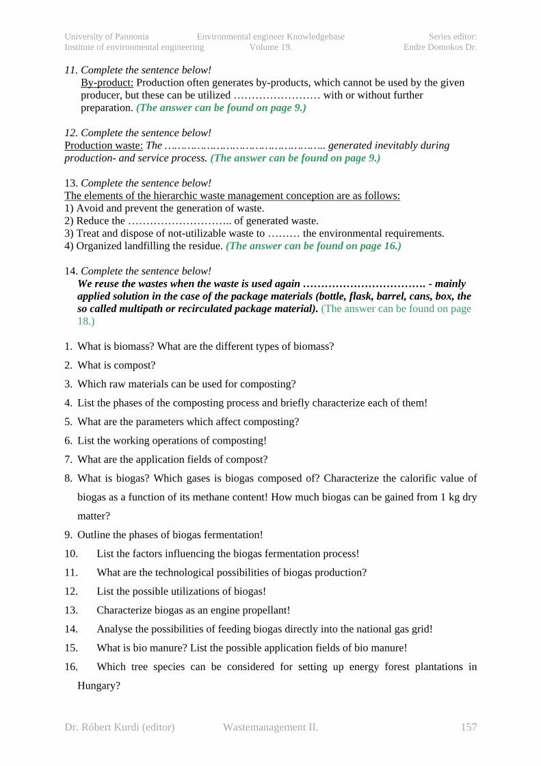
University of Pannonia Environmental engineer Knowledgebase Series editor: Institute of environmental engineering Volume 19. Endre Domokos Dr.
11. Complete the sentence below! By-product: Production often generates by-products, which cannot be used by the given producer, but these can be utilized …………………… with or without further preparation. (The answer can be found on page 9.)
12. Complete the sentence below! Production waste: The ………………………………………….. generated inevitably during production- and service process. (The answer can be found on page 9.) 13. Complete the sentence below! The elements of the hierarchic waste management conception are as follows: 1) Avoid and prevent the generation of waste. 2) Reduce the ……………………….. of generated waste. 3) Treat and dispose of not-utilizable waste to ……… the environmental requirements. 4) Organized landfilling the residue. (The answer can be found on page 16.) 14. Complete the sentence below!
We reuse the wastes when the waste is used again ……………………………. - mainly applied solution in the case of the package materials (bottle, flask, barrel, cans, box, the so called multipath or recirculated package material). (The answer can be found on page 18.)
1. What is biomass? What are the different types of biomass?
2. What is compost?
3. Which raw materials can be used for composting?
4. List the phases of the composting process and briefly characterize each of them!
5. What are the parameters which affect composting?
6. List the working operations of composting!
7. What are the application fields of compost?
8. What is biogas? Which gases is biogas composed of? Characterize the calorific value of
biogas as a function of its methane content! How much biogas can be gained from 1 kg dry
matter?
9. Outline the phases of biogas fermentation!
10. List the factors influencing the biogas fermentation process!
11. What are the technological possibilities of biogas production?
12. List the possible utilizations of biogas!
13. Characterize biogas as an engine propellant!
14. Analyse the possibilities of feeding biogas directly into the national gas grid!
15. What is bio manure? List the possible application fields of bio manure!
16. Which tree species can be considered for setting up energy forest plantations in
Hungary?
Dr. Róbert Kurdi (editor) Wastemanagement II. 157

University of Pannonia Environmental engineer Knowledgebase Series editor: Institute of environmental engineering Volume 19. Endre Domokos Dr.
17. List the types of energy forest plantations!
18. What advantages can be attained using energy tree plantations?
19. Which are the parameters that should be analysed before energetic utilization of wood?
20. What is wood briquette? Outline its major properties and the principles of fabrication!
21. What is pellet? Outline its major properties and the principles of fabrication!
22. What is the difference between fuels and engine propellants?
23. What is biodiesel? What plants can it be produced from?
24. Outline the process of biodiesel production!
25. What is bioethanol? What plants can it be produced from?
26. Outline the process of bioethanol production!
27. What is pyrolysis? What compounds are formed as a result of biomass pyrolysis?
28. What are the factors influencing pyrolysis? What are the advantages and disadvantages
of pyrolysis?
29. Characterize the four most important pyrolysis technologies!
30. What is gasification?
Dr. Róbert Kurdi (editor) Wastemanagement II. 158
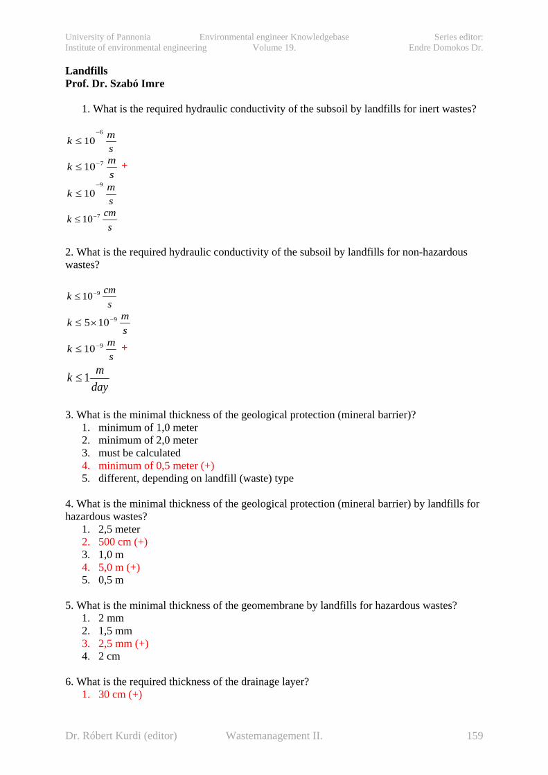
University of Pannonia Environmental engineer Knowledgebase Series editor: Institute of environmental engineering Volume 19. Endre Domokos Dr.
Landfills Prof. Dr. Szabó Imre
1. What is the required hydraulic conductivity of the subsoil by landfills for inert wastes?
smk
6
10−
≤
smk 710−≤ +
smk
9
10−
≤
scmk 710−≤
2. What is the required hydraulic conductivity of the subsoil by landfills for non-hazardous wastes?
scmk 910−≤
smk 9105 −×≤
smk 910−≤ +
daymk 1≤
3. What is the minimal thickness of the geological protection (mineral barrier)?
1. minimum of 1,0 meter 2. minimum of 2,0 meter 3. must be calculated 4. minimum of 0,5 meter (+) 5. different, depending on landfill (waste) type
4. What is the minimal thickness of the geological protection (mineral barrier) by landfills for hazardous wastes?
1. 2,5 meter 2. 500 cm (+) 3. 1,0 m 4. 5,0 m (+) 5. 0,5 m
5. What is the minimal thickness of the geomembrane by landfills for hazardous wastes?
1. 2 mm 2. 1,5 mm 3. 2,5 mm (+) 4. 2 cm
6. What is the required thickness of the drainage layer?
1. 30 cm (+)
Dr. Róbert Kurdi (editor) Wastemanagement II. 159

University of Pannonia Environmental engineer Knowledgebase Series editor: Institute of environmental engineering Volume 19. Endre Domokos Dr.
2. 50 cm 3. 0,25 m 4. 2×0,3 m
7. Choose the correct answer!
1. The thickness of the drainage layer can be reduced based on sizing. 2. The thickness of the drainage layer must be a minimum of 30 cm after sizing. (+) 3. The thickness of the drainage layer can be reduced by 30 cm-s after sizing. 4. The thickness of the drainage layer can be reduced in case of small amounts of
leachate. 5. The thickness of the drainage layer must be a minimum of 10 cm in case of landfills
with closed roof. 8. What is the required thickness of the built mineral barrier layer by the closure of landfills for non-hazardous wastes according to the current regulations?
1. Mimimum 1,0 m 2. 2×30 cm 3. 0,5 m 4. 2×25 cm (+) 5. 1,5 m
9. What is the required thickness of the built mineral barrier layer by the closure of landfills for hazardous wastes according to the current regulations?
1. Mimimum 1,0 m 2. 4×30 cm 3. 4×25 cm 4. 2×25 cm (+) 5. 1,5 m
10. Is it required to build in a geomemrane by the closure of landfills for non-hazardous wastes according to the current regulations?
1. Yes 2. No (+) 3. optional
11. Is it required to build in a geomemrane by the closure of landfills for hazardous wastes according to the current regulations?
1. Yes (+) 2. No 3. optional
12. Choose the correct definition!
1. Compaction must be performed one by one on every single layer, the maximum thickness (d) of the layers in laid condition: 20 cm < d < 25 cm.
2. Compaction must be performed one by one on every single layer, the maximum thickness (d) of the layers in compacted condition: 25 cm < d < 30 cm.
3. Compaction must be performed one by one on every single layer, the maximum thickness (d) of the layers in compacted condition: 20 cm < d < 25 cm. (+)
4. Compaction must be performed one by one on every single layer, the maximum thickness (d) of the layers in compacted condition: 20 cm < d < 30 cm.
Dr. Róbert Kurdi (editor) Wastemanagement II. 160

University of Pannonia Environmental engineer Knowledgebase Series editor: Institute of environmental engineering Volume 19. Endre Domokos Dr.
13. Choose the correct definition(s)!
1. The criterion of favourable construction water content: wopt < wbeépített < w95 (+) 2. The criterion of favourable construction water content: wopt < wbeépített < w90 3. The criterion of favourable construction water content: w90 < wbeépített < wopt 4. The criterion of favourable construction water content: w95t < wbeépített < w90 5. The criterion of favourable construction water content: must be higher than wopt 6. The construction must be performed on the wet side of the Proctor curve. (+)
14. Choose the liners that are not liners made of alternative natural materials!
1. mixed soil enriched with clay minerals, 2. mixed soil enriched with clay minerals and polymer additives, 3. geomembrane (+) 4. geosynthetic clay liners 5. silty sandflour (+) 6. mixed soil enriched with clay minerals, polymer additives and water glass
15. Choose the correct answer(s)! The material of the leachate collection system must be:
1. 16/32 graded gravel (+) 2. 24/40 graded gravel (+) 3. sandy gravel, k<10-3 m/s 4. breakstone, k<10-3 m/s 5. silt+clay content minimum 0,5 % 6. CaCO3 content minimum 20 %
16. Choose the correct answer(s)! The sizes and parameters commonly used by drainage system construction are the following:
1. Transverse slope (ik): ≥ 3% (+) 2. Transverse slope (ik): ≥ 3 ‰ 3. Longitudinal slope (ih): 1-2 % (+) 4. Longitudinal slope (ih): 0,5 % 5. Longitudinal slope (ih): 5 ‰ 6. Transverse slope (ik): ≥ 1°
17. Choose the correct answer(s)! The recommended thickness of the filtering layer above the drain pipe is (d: the diameter of the drain pipe):
1. 1d 2. 2d (+) 3. 50 cm 4. 30 cm 5. 2,5d
18. Choose the incorrect answer(s)! If processes in the landfill are completed:
1. Temporary closure suggested. 2. Final closure suggested. (+) 3. Elimination of the landfill suggested.
Dr. Róbert Kurdi (editor) Wastemanagement II. 161

University of Pannonia Environmental engineer Knowledgebase Series editor: Institute of environmental engineering Volume 19. Endre Domokos Dr.
19. Choose the incorrect answer(s)! If processes in the landfill are not completed:
1. Temporary closure suggested. (+) 2. Final closure suggested. 3. Elimination of the landfill suggested.
20. Choose the incorrect answer(s)! Elimination of the landfill suggested:
1. If there are only small amounts of waste. (+) 2. If processes in the landfill are completed. 3. If processes in the landfill are not completed. 4. If landfilling ended more than 10 years ago. (+) 5. If there is another landfill close to this one to transport the waste safely. (+)
21.ENG Fill in the missing values in the table!
The requirements of the construction of leachate collection system Landfills for
inert wastes Landfills for non-hazardous wastes
Landfills for hazardous wastes Upper drainage layer
Second drainage and control layer
Thickness (m) 0,3-0,5 0,3-0,5 0,3-0,5 0,3 Material 16/32 or
24/40 graded gravel
16/32 or 24/40 graded gravel
16/32 or 24/40 graded gravel
_
Required hydraulic conductivity k (m/s)
>10-3 >10-3 >10-3 >10-3
Red values left blank, must be entered! 22. .ENG Fill in the missing values in the table!
The requirements of the construction of leachate collection system Landfills for
inert wastes Landfills for non-hazardous wastes
Landfills for hazardous wastes Upper drainage layer
Second drainage and control layer
Thickness (m) 0,3-0,5 0,3-0,5 0,3-0,5 0,3 Material 16/32 or
24/40 graded gravel
16/32 or 24/40 graded gravel
16/32 or 24/40 graded gravel
_
Required hydraulic conductivity k (m/s)
>10-3 >10-3 >10-3 >10-3
Red values left blank, must be entered! 23. .ENG Fill in the missing values in the table!
Dr. Róbert Kurdi (editor) Wastemanagement II. 162
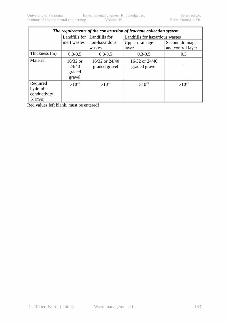
University of Pannonia Environmental engineer Knowledgebase Series editor: Institute of environmental engineering Volume 19. Endre Domokos Dr.
The requirements of the construction of leachate collection system Landfills for
inert wastes Landfills for non-hazardous wastes
Landfills for hazardous wastes Upper drainage layer
Second drainage and control layer
Thickness (m) 0,3-0,5 0,3-0,5 0,3-0,5 0,3 Material 16/32 or
24/40 graded gravel
16/32 or 24/40 graded gravel
16/32 or 24/40 graded gravel
_
Required hydraulic conductivity k (m/s)
>10-3 >10-3 >10-3 >10-3
Red values left blank, must be entered!
Dr. Róbert Kurdi (editor) Wastemanagement II. 163
University of Pannonia Environmental engineer Knowledgebase Series editor: Institute of environmental engineering Volume 19. Endre Domokos Dr.
14. References 14.1. References with environmental and waste management chapter [1] Handbuch des Umweltschutzes und der Umweltschutztechnik (Hrsg. Heinz Brauer). Band 1 és Band 2, Springer, Berlin, 1995. [2] Csőke, B - Olessák, D.: Hulladékgazdálkodás általános kérdései, alapelvei,
Hulladékgazdálkodási szakmai Füzetek 1. (KVVM és a Köztisztasági Egyesülés kiadványa). Komáromi Nyomda és Kiadó Kft., Komárom, 2003.
[3] Taschenbuch der Umwelttechnik. (Hrsg. Schwister, K.). Fachbuchverlag Leipzig, 2003 [4] Takács, S.: Az ember és környezete. Miskolci Egyetemi Kiadó, Miskolc, 2002 [5] Förstner, U.: Környezetvédelmi technika. Springer Hungarica. Budapest, 1993 [6] Környezettechnika. (Szerk.: Barótfi, I.) Mezőgazda Kiadó, Budapest, 2000 [7] Pahl, M.H.: Erfassen. Lagern und Entsorgen von festen Abfallstoffen im Betrieb.
Universität - GH – Paderborn [8] Csőke, B.: A hulladék, mint nyersanyag. BKL, BÁNYÁSZAT (HU ISSN 522-3512), 136
évfolyam (2003), 6.szám, 415-430 [9] Schischke, K – Hagelüken, M. – Steffenhagen, Gr.: Bevezetés az Öko-Design Stratéhiába-
mit, miért és hogyan. (Fraunhofer IZM, Berlin). (Az elhasznált elektromos és elektronikai termékek kezelésével foglalkozó – 2000-ben elfogadásra kerülő – EU direktíva hazai alkalmazásának előkészítése, annak hatásaival, és az életciklus elemzés tudományos eszközével (EUREKA-SCARE nemzetközi projekthez csatlakozva). Támogatás az I. Országos Környezettudományi és Természetvédelmi Kutatási Pályázat keretében, 1998-2000.) www.EcoDesignArc.info
Dr. Róbert Kurdi (editor) Wastemanagement II. 164
University of Pannonia Environmental engineer Knowledgebase Series editor: Institute of environmental engineering Volume 19. Endre Domokos Dr.
Refenreces with [I] IAEA Safety Series No. 111-G-1.1. Classification of Radioactive Waste,1994 [II] IAEA Safety Series No. GSG-1 Classification of Radioactiva Waste, 2009 [III] Radioactive Waste Management Programmes in OECD/NEA member countries, Hungary, 2009 [IV] Recommendations of the ICRP. Pubiication 60. Annals of the ICRP Vol. 21. Nos. 1-3. Pergamon Press. Oxford and New York, 1992 [V] The Environmental and Ethical Basis of Geological Disposal of Long-Lived Radioactive Wastes OECD/NEA, 1995 [VI] IAEA Technical Reports Series No. 413A Scientific and Technical Basis for Geological Disposal of Radioactive Wastes, 2003 [VII] Progress towards geological disposal of radioactive waste: Where do we stand?” OECD/NEA, 1999 [VIII] The 8th, 9th and 10th mid and long term plan of limited partnership company for radioactive waste management for the activities to be financed from the Central Nuclear Financial Fund (CNFF), Hungary, 2008 – 2010 [IX] RHK Kht. „Az RHK Kht. tizedik közép- és hosszú távú terve a Központi Nukleáris Pénzügyi Alapból finanszírozandó tevékenységekre”, 2010 május [X] Kovács L. et al. Mecsekérc Rt: Kutatási terv a BAF minősítését célzó Középtávú Program 1. kutatási fázisához (2004-2006), Mecsekérc Rt. Pécs, 2004 [XI] Takáts F et al: Műszaki megvalósítási koncepcióterv a BAF minősítését célzó Középtávú Program 1. kutatási fázisához, T S Enercon Kft. 2005 [XII] Kovács L. et al. Mecsekérc Rt: A BAF minősítésének Rövidtávú Programja. Kutatási zárójelentés. 1. kötet: A Rövidtávú Program időszakában kivitelezett földalatti és külszíni kutatóobjektumok; 2. kötet: Nagy léptékű földtani vizsgálatok, regionális tektonikai és szedimentológiai modell kidolgozása; 3. kötet Földtani dokumentációs munkák a BAF megismerésére; 4. kötet: Ásvány-kőzettani, kőzetgeokémiai és izotóptranszport vizsgálatok; 5. kötet: Hidrogeológiai, hidrogeokémiai vizsgálati program; 6. kötet: Kőzetmechanikai, geotechnikai vizsgálati program; 7. kötet: In situ és laboratóriumi geofizikai vizsgálatok; Összefoglaló kötet. Pécs-Paks, 1999 [XIII] Kovács L. et al. 1999: A BAF minősítésének Rövidtávú Programja – Kutatási Zárójelentés. Összefoglaló (9.) kötet. Kézirat, Pécs, 1999. március. [XIV] Hámos G. et al. 1999: A BAF minősítésének Rövidtávú Programja – Kutatási Zárójelentés. Földtani dokumentációs munkák a BAF megismerésére (3. kötet). Kézirat, Pécs, 1999. március. [XV] Csicsák J. et al. 1999: A BAF minősítésének Rövidtávú Programja – Kutatási Zárójelentés. Hidrogeológiai, hidrogeokémiai vizsgálati program (5. kötet). Kézirat, Pécs, 1999. március. [XVI] Berta Zs. et al. 1999: A BAF minősítésének Rövidtávú Programja – Kutatási Zárójelentés. In situ és laboratóriumi geofizikai vizsgálatok (7. kötet). Kézirat, Pécs, 1999. március. [XVII] Kovács, L. (ed.), 1999: Digest on the results of the short-term characterisation programme of the Boda Claystone Formation, Pécs, Mecsekérc Ltd. Paks, PURAM [XVIII] Report of the WATRP Review Team on the evaluation of the Hungarian Work on Selecting a site for Disposal of Low and Intermediate Level Waste (A WATRP vizsgálatot
Dr. Róbert Kurdi (editor) Wastemanagement II. 165

University of Pannonia Environmental engineer Knowledgebase Series editor: Institute of environmental engineering Volume 19. Endre Domokos Dr.
végző csoport jelentése a kis és közepes aktivitású hulladékok végleges elhelyezésére szolgáló telephely kiválasztásával kapcsolatos magyar tevékenység értékeléséről). — Manuscript (kézirat), Országos Atomenergia Hivatal, Budapest; Magyar Állami Földtani Intézet, Budapest, Tekt. 707, 2000 [XIX] A BAF kutatás hosszú távú programját aktualizáló tartalmi, pénzügyi és ütemezési koncepció” elkészítésének munkaterve Mecsekérc Zrt.;RHK Kht. 2007 [XX] Kovács, L. Benkovics, I. Szűcs, I. et al.: Exploration project for the first phase (2004-2006) of the Medium-Term Program aiming at the qualification of the BAF Mecsekérc Zrt.; RHK Kht. 2003
Dr. Róbert Kurdi (editor) Wastemanagement II. 166

University of Pannonia Environmental engineer Knowledgebase Series editor: Institute of environmental engineering Volume 19. Endre Domokos Dr.
Reference with [i] Orosz, Z. – Fazekas, I. (2008): Challenges of municipal waste management in Hungary. AGD Landscape & Environment 2 (1) 2008. 78-85.(Burzus, Adrienn) For more references see: [ii] Buruzs, A., Kovács, B.: Regionális hulladékgazdálkodási rendszerek tervezése, létesítése, működtetése és fenntarthatósága (not published yet) (Burzus, Adrienn)
Dr. Róbert Kurdi (editor) Wastemanagement II. 167