wastewater treatment facility products / specifications
TRANSCRIPT

Wastewater Treatment Facility
Products / Specifications
All water construction in the City of Oconomowoc shall be in accordance with the (SWS) Standard Specifications for Sewer and Water Construction in Wisconsin, 6th Edition, Addendum No. 1. dated December 22, 2004, and Addendum No. 2. dated April 22, 2008.
Gravity Sanitary Sewer
A. Pipe: 1) Polyvinyl chloride and fittings solid wall:
a) 4 –inch through 15 inch: Type PSM, ASTM D-3034, SDR 35. b) 18-inch: Type PSM, ASTM F-679, 12454C. c) SWS 8.3.0 AND 8.10.0.
2) Reinforced concrete: a) Circular Pipe: ASTM C-76, wall thickness C, Class III-V. b) Joints: Type R-4 air test gasket, ASTM C-361.
1) SWS 8.3.0 and 8.6.0.
B. Pressure Rated Pipe: If not shown of Drawings use one type from the following: 1) Polyvinyl chloride pipe:
a) 4-inch through 12-inch AWWA C900 SDR 18 or less. b) 14-inch though 36-inch AWWA C905 SDR 18 or less
2) Ductile iron: a) AWWA thickness Class 52 with cement lining b) Tyton gasketed joint pipe c) Rubber gasketed d) Polyethylene film wrap: SWS 8.21.0.
3) Fittings for PVC and ductile iron pipe shall follow SWS 8.22 and: a) Joints:
1) Buried: Mechanical. 2) In structures: Flanged.
b) Pressure rating: 1) Full body: 250 PSI. 2) Compact: 350 PSI.
c) Material: 1) Ductile iron class 52 wall thickness. 2) Bituminous exterior coating per ANSI/AWWA C110/A21.10. 3) Cement lined and bituminous coated interior per ANSI/AWWA C104/A21.4. 4) Cor-Blue tee bolts
C. Bulkhead and Plug: SWS 3.2.25.
D. Structures: 1) Manholes: SWS 3.5.0 and 8.39.0. 2) Steps: Follow SWS 3.5.4.(g). 3) Frame: SWS file No. 14A.
a) Neenah 1550-0002 Oconomowoc Standard b) Follow Exhibit SAN-03 of City of Oconomowoc Specifications.
4) Cover: Self sealing, concealed pick hole, no vents. Follow Exhibit SAN 03 of City of Oconomowoc Specifications.
a) Neenah 1050-5210. b) Marked “Sanitary”. c) Manhole adjusting rings (steel riser) not allowed.
5) Bolt-down frame/cover: SWS File No. 32 except use Neenah 1916C. Use bolt down cover for manholes located on private property, out-lots or as directed by the City.
6) Internal rubber sleeves: Cretex Specialty Products or NPC Flex Rib. 7) Pipe to manhole connection: Follow SWS 3.5.7. up to 21-inch pipe. 8) Pipe to manhole seal: 24-inch and larger, use NPC Contour Seal. 9) Frame and chimney sealants: SWS 8.42.0. 10) Flat decks – HS2O loading 11) Mastic: Trowlable Tremco-60. 12) Provide two green fiberglass posts 4’ high for manholes in easements (Part No. USA Bluebook
70457).
E. Sampling or sampling / gauging manholes. 1) All commercial / industrial sewers shall be installed with a sampling or sampling / gauging
manhole. 2) Type of structure required will be determined by City of Oconomowoc WWTF based on the type
of facilities connected to the sewer. 3) Sampling manhole:
a) Follow SWS 3.5.8 (42” diameter manhole) b) Follow 2.02D. for manhole requirements. c) Follow Exhibit SAN-04 City of Oconomowoc Specifications for sampling configuration. d) Flat deck: HS2O loading.
4) Sampling / gauging manhole: a) Follow SWS 3.5.8. b) Follow 2.05D for manhole requirements. c) Frame: Neenah R-1740B pr R-1916H. d) Cover: Self sealing, concealed pick hole, no vents e) Follow Exhibit SAN-05 City of Oconomowoc Specifications.
F. Risers:
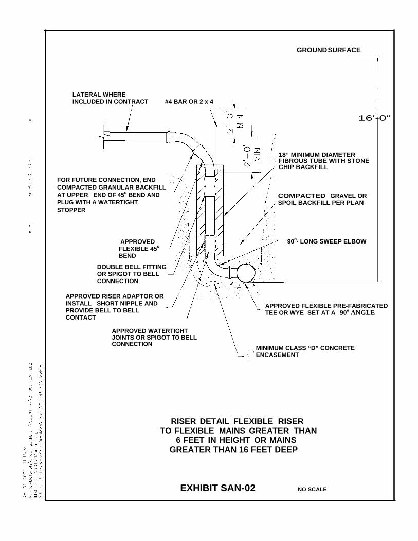
1) SWS 3.2.26. 2) For flexible-riser-to-flexible-main greater than 6 feet, or main greater than 16 feet deep. Follow
Exhibit SAN-02 of City of Oconomowoc Specifications. 3) Where design of new sanitary risers is necessary, the use of double risers is encouraged.
G. Laterals:
1) SWS 5.3.10 and 5.3.11 and same material as main 2) Lateral size:
a) One and two family: 4-inch minimum. b) Commercial: 6-inch minimum.
3) Test tee with plugs. 4) Connection to main: Wyes. 5) Adapt pressure rated pipe to SDR35 with manufactured (molded) fittings.
Sanitary Sewer Force Main A. Pipe: If not show on Drawings, use one type from the following:
1) PVC, with integral elastomeric bell-and-spigot joints, with the following: a) AWWA C-900 for 6 through 12-inch diameter. Class 150 pressure pipe with DR 18 or
less. SWS 8.51.0. b) AWWA C-905 for 14 through 36-inch diameter. CIOD pressure pipe rated 235 PSI with
DR 18 or less. SWS 8.51.0. c) ASTM D-2241 with Plastics Pipe Institute hydrostatic design stress of 200 PSI and SDR of
26 or less. 2) Ductile iron:
a) SWS 8.18.0. b) AWWA thickness Class 52 with polyethylene lining. c) Bell and spigot push-on joint SWS 8.18.2. d) Polyethylene film wrap: SWS 8.21.0
3) Polyethylene: a) Material designation: PPI PE 3408. b) Material designation: Type III, Class C, Category 5, Grade P34. c) Cell classification: 345434C per ASTM D3350. d) Pressure class: As approved by City Engineer.
B. Fittings for ductile iron:
1) Joints: a) Buried: Mechanical b) In structures: Flanged.
2) Pressure rating: a) Full body: 250 PSI. b) Compact: 350 PSI.
3) Material: a) Ductile iron:
1) Ductile iron class 52 wall thickness. 2) Bituminous exterior coating per ANSI/AWWA C110/A21.10. 3) Cement lined and bituminous coated interior per ANSI/AWWA C104/A21.4. 4) Cor-Blue tee bolts.
C. Restrained joints:
1) Strapping following SWS 4.9.0. 2) EBAA Iron Mega-lug. 3) All Star Pipe Products All-grip.
D. Fittings for polyethylene pipe:
1) ASTM D32.61. 2) Pressure class:
a) Molded fittings: Match pipe. b) Fabricated fittings: Increase pressure rating one class.
3) Butt fused or flanged. 4) Exposed: Molded flange adaptor with ductile iron or stainless steel backup ring and stainless
steel bolts. 5) Buried: Molded mechanical restrained joint adaptor with stainless steel internal stiffener and
ductile iron or stainless steel backup ring with Cor-Ten hardware.
E. Valves: DeZurick Series 100 plug style.
F. Valve boxes: 1) Cast iron 3-piece assembly, size DD, and cover marked “Sewer”. 2) Threaded base with notched top for adjustment. 3) Manufacturers: Tyler 6860, Sigma VC630DD, Star VB DHD DW. 4) SWS 8.29.0. 5) Valve box adaptors: Adaptors, Inc.

G. Valve stem extenders: 1) Securely attached to valve operator. 2) Extend to 4 feet (plus or minus 3-inches) below finished grade. 3) For 6 feet and longer provide solid shaft. 4) Epoxy coated iron with stainless steel pins or bolt. 5) Spacer ring at 3-inch below operating nut.
H. Structures:
1) Valve manholes: SWS 3.5.0 and 8.39.0. 2) Manholes: SWS 3.5.0 and 8.39.0. 3) Steps: Follow SWS 3.5.4.(g). 4) Frame: Neenah 1550-0002 Oconomowoc Standard. 5) Cover
a) Self sealing, concealed pick hole, no vents. b) Follow Exhibit SAN-03 of City of Oconomowoc Specifications. c) Neenah 1050-5210. d) Marked “Sanitary”. e) Manhole adjusting rings (steel riser) not allowed.
6) Bolt-down frame / cover: SWS File No. 32 except use Neenah 16916 C. Use bolt-down cover for manholes located on private property, out-lots, or as directed by the City.
7) Internal rubber sleeves: Cretex Specialty Products or NPC Flex Rib. 8) Pipe to manhole connection: Follow SWS 3.5.7. up to 21-inch pipe. 9) Pipe to manhole seal: 24-inches and larger, use NPC Contour Seal. 10) Frame and chimney sealants: SWS 8.42.0. 11) Flat decks: H2SO loading. 12) Mastic: Trowable Tremco-60. 13) Provide two green fiberglass posts 4” high for manholes in easements (Part No. USA Bluebook
70457).
I. Air release assemblies: 1) Vault: SWS 4.11.0. except include:
a) Valve stem extenders. b) Lid: Plan or “Sewer” c) Drain stop:
1) Female iron pipe inlet and flared copper outlet. Ford B21-333. 2) A.Y. McDonald 6105 with A. Y. McDonald 4753 copper flare-by-male iron pipe
thread.
M. Bedding and cover materials: 1. Limestone chips: SWS 8.43.2. 2. Sand: SWS 8.43.2 Table 35. 3. Around and over Underground Facilities: Follow respective owner’s requirements. 4. Cover: Same material as bedding.
N. Backfill:
1. Granular backfill: SWS 8.43.4. 2. Spoil backfill: SWS 8.43.5. 3. Aggregate slurry backfill: SWS 8.43.8. 4. Crushed road gravel backfill: State Specifications 305.2, 3/4 –inch crushed road gravel,
gradation No. 2.
O. Warning tape: 1. “THERRA TAPE EXTRA STRENGTH 540” by Reed Industries, Inc. or “Shieldtec”, by Empire
Level Manufacturing Corporation. 2. Tape shall read: “CAUTION: SANITARY LINE BURIED BELOW”. 3. Color (from State Statutes 182.0175 and ANSI Standard 253.1).
a) Water – Green 4. Width: 3-inches

P. Detector wire: 1. SWS 4.3.14. 2. For open-cut: Direct –burial-rated insulated AWG # 10 copper conductor. 3. For trenchless installation: Aircraft cable, nylon-coated stainless –steel, 3/8-inch diameter. 4. Splices: SWS Drawing File No. 24B. Use plastic heat shrink coating kit for 3M splice kit per
Oconomowoc Utilities. 5. Color: (from State Statutes 182.0175 and ANSI Standards 253.1):
a) Sanitary: Green 6. Anodes: 1 pound magnesium. (Detailed specifications and drawings to be provided by
Oconomowoc Utilities. Q. Location boxes for tracer wire access:
1. Sewer, force main buried: a) Top section valve box, size DD, 26-inch length. b) Cover: Marked “SEWER”. c) Hardwood blocking.
2. On buildings: a) Weather-proof electrical box. b) Marked “SEWER” to match buried pipeline.
R. Surface Restoration:
1. Asphalt pavement: SWS 2.7.3 a) Residential: 4-inch total pavement: 2-1/2 –inch Binder, 1-1/2-inch surface. b) Industrial: 5-inch total pavement: 3-1/2-inch Binder, 1-1/2-inch surface.
2. Concrete pavement: SWS 2.7.3. a) Residential and commercial: Replace in kind.
1) Do not use Calcium Chloride. 3. Stone base:
a) Residential: 8-inches of total depth. 1) Lower: 5-inches 1-1/4-inch gradation. 2) Upper: 3-inches 3/4-inch gradation
b) Commercial: 12-inches of total depth. 1) Lower: 8-inches 1-1/4-inch gradation 2) Upper: 4-inches 3/4-inch gradation.
S. Lawn restoration: SWS 2.7.4 Type C.
T. Curb and gutter restoration: Follow SWS 2.7.3. Do not add Calcium Chloride. 1. Follow Exhibit PAV-05 of City of Oconomowoc Specifications.
U. Concrete sidewalk: 1. Follow Exhibit PAV-05 of City of Oconomowoc Specifications. 2. SWS 2.7.3.
V. Insulation:
1. SWS 8.50.0.
Execution
Gravity Sanitary Sewer Installation
A. Before starting, bulkhead and / or plug the connection to the existing sewer. Leave in place until new sewer has been cleaned and accepted.
B. Bedding and cover: 1. Stone chips 2. Follow SWS 3.2.6(b) Class B
C. Follow SWS Part III.
D. Manholes: 1. Steps:
a) Do not locate over pipe wall penetrations. Follow SWS File No. 13. 2. Wrap external surface of all joints below the water table with MAC wrap. 3. Exterior chimney treatment:
a) Provide 1/4-inch minimum thickness, trowelable mastic extending over chimney joints and frame.
b) Provide plastic wrap (minimum 4 mil) around all mastic areas before backfilling. 4. Do not back-plaster chimney interiors. 5. Pour benches to springline. 6. Fill void above manhole pipe boot with mastic and trowel mortar in place. 7. Set manhole rims to 0-inch to minus 1/4-inch below finish grade. 8. Wood shims are not allowed for any reason. 9. Place 10-foot radius ramp around manholes when binder course is placed. 10. Manhole vacuum testing:
a) Test time of mercury drop from 10-inches to 9- inches. b) Use Exhibit SAN-07 City of Oconomowoc Specifications for testing. c) Test prior to placement of frame.
11. Internal seal testing: a) Test all internal seals prior to final completion. b) Pour one gallon of dyed water into top of seal. c) Seal must hold for minimum of one minute. d) Retest until passes test. e) Allow Utility Engineer to witness testing of seals.
E. Laterals: Follow SWS Part V and:
1. 1/4-inch per foot maximum slope. 2. Provide 2 by 6-inch hardwood marker at end of lateral from invert of lateral to 2 feet above
finished grade for new laterals. 3. Provide test tee at right-of-way line. 4. Stamp face of curb and gutter with “S” over sewer location. 5. Laterals should be placed in the center of the lot. 6. Laterals to be staked by design Engineer prior to installation. 7. Maximum depth at property line shall be at 12 feet to finish grade. Invert elevations shall be
supplied on the plans.
F. Interceptor connection: 1. All interceptor connections will be evaluated and accepted on a case-by-case basis. 2. All connections must be approved in writing by the WTF prior to connection to system.
G. Sanitary sewer repairs / relays:
1. Pump around work zone. 2. Do not allow sanitary flow to migrate through work zone, infiltrate into soils or be conveyed in
any manner open to air or in contact with soil or groundwater. 3. Submit a “pump around” operation plan to City for approval before starting construction. Include
a detail of equipment to be use, location of equipment, hours of operation, and safeguards to assure proper operation, 24-hour emergency contact numbers.
4. Submit a “flume” operation plan to the City for approval, prior to starting construction. Include a detail of equipment to be use, location of equipment, hours of operation, and safeguards to assure proper operation, 24-hour emergency contact numbers.
5. Follow “pump around” plan during working hours. Follow “flume” plan during non-working hours. 6. City may stop work if the construction activities deviate from the “pump around” and or “flume”
plans or if construction activities are not performed to the satisfaction of the City.
H. Pressure test: SWS 3.7.3.
I. Go-No-Go Test: SWS 3.2.6(i)4.
J. Cleaning and televising of mains: 1. WTF operators shall be responsible for videotaping of sanitary sewer upon notification of
completion of the following items: a) Manhole benches poured. b) Surfacing restored. c) Pipe work successfully tested.
2. Cost of all videotaping and cleaning of lines shall be the responsibility of the Developer.
Sanitary Sewer Force Main Installation
A. Follow SWS Part IV (Delete 4.3.12). B. Bedding and cover: Stone chips. C. Pressure Test:
1. Follow SWS 4.15.2 except test at pipe pressure rating or 150 PSI, whichever is less. 2. Before testing, repair or replace piping, valves, fittings, structures or other parts of system which
have visible defects or leakage even if leakage or pressure loss may be below allowable limits.
D. Manhole: Follow 3.02.D. E. Polyethylene:
1. Butt-fuse joints following ASTM D2657 and manufacturer’s recommendations. 2. Connect to flanged pipe with molded flange adaptor with ductile iron backup ring. 3. Install following ASTM D2321, SWS, and manufacturer’s recommendations. 4. Provide embedment material from 6-inches below pipe to 12-inches above top of pipe and
compact to 85 percent Standard Proctor density (AASHTO T-99).
F. Protect cut ends and bell fittings with factory-supplied, field-applied touchup coating. G. Warning tape: Place 24-inches below finished grade for:
1. All force mains and laterals. 2. All sanitary sewer mains and laterals.
H. Detector wire:
1. Place a maximum of 6-inches directly: 1. All force mains and laterals. 2. All sanitary sewer mains and laterals.
2. Do not splice between location boxes without Water Utility’s approval.
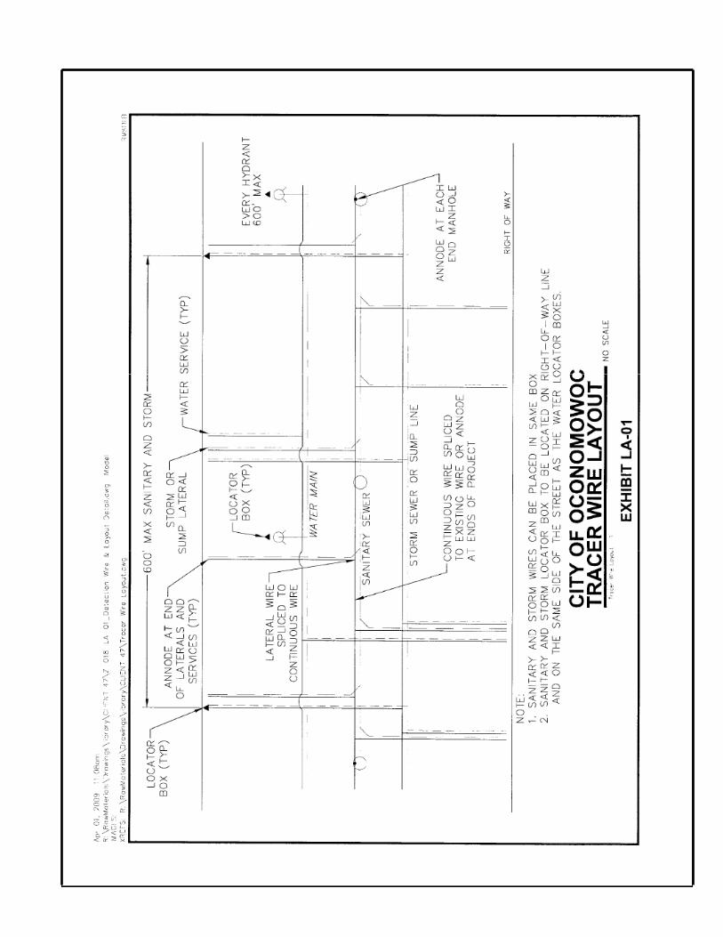
I. Install location boxes at: 1. Sewers, laterals and sump lines.
a) 600 feet maximum intervals. b) Every third lot.
1) On same side of street as water main. 2) At lot line.
c) Sanitary, storm wires can be placed in same location box.
J. Demonstrate continuity of detector wires to Water Utility or Inspector: 1. Provide a temporary above-ground wire between adjacent location boxes. Connect ohmmeter in
a series loop with detector wire and above-ground wire. Circuit resistance shall not exceed 5 ohms.
2. Water main shall be tested with 300 Amps AC or DC for 15 minutes. Replace and retest sections failing test.
K. Test locating. Contact Water Utility to locate all utilities. 1. After completion of continuity test. 2. Before acceptance for use.

L. Cleanup: 1. At end of each working day. 2. As needed during the day to avoid creating hazards or complaints. 3. As requested by City.
M. Insulation:
1. Follow SWS 4.17.2 and SWS File No. 48 when depth of cover is less than 4-1/2 feet over water main.
N. Trench backfilling and consolidation: 1. In existing pavement areas, which will not be reconstructed from 5 feet behind the back of the
curb or edge of pavement in paved areas and driveways: a) Aggregate slurry. b) Top 12-inches to be 1-1/4 crushed limestone.
2. In future pavement areas form 5 feet behind the back of the curb or edge of pavement in paved areas and driveways – granular.
3. Other areas: Spoil will be allowed only with written approval by OWNER. 4. Around and over Underground Utilities: Follow respective owner’s requirements.
O. Consolidation:
1. Compaction by one of the following methods: a) Mechanically compact trench backfill. Follow SWS 2.6.14(b). b) Flush trench backfill. Follow SWS 2.6.14(a).
2. Proof roll all trenches.
Submittal Requirements for Sewage Pumping Stations
Shop Drawings
Prior to construction or installation of equipment, furnish four bound sets of submittal information to City Engineer's office for review and approval. Include product data, shop drawings, product samples and scale layout drawings as listed below:
A. Structures:
1. Wet well and valve chamber. a) Indicate the location, orientation and clearance distance of the check valve outside
lever and weights. b) Indicate orientation of access hatches, safety grates, pump guide rails, float cable
hooks, and incoming sewer main(s). 2. Access hatches. 3. Sewage piping materials. 4. Buoyancy calculations. 5. Piping layout. 6. Control elevations.
B. Equipment: 1. Hydraulic system curve, wet well cycle time calculations. 2. Pumps, equipment and performance curves. 3. Valves, shutoff and check. 4. Floats/Control system.

C. Electrical: 1. Wiring diagrams. 2. Generator building layout. 3. Building structural design. 4. Building equipment specifications. 5. Generator. 6. Automatic transfer switch. 7. Pump control panel. 8. Telemetry equipment.
D. Site:
1. Site plan drawn to scale, 1" = 20'. 2. Landscaping plan.
E. Samples:
Furnish product samples to City Engineer's office for selection prior to installation for the following: 1. Generator Building
a) Exterior wall color. b) Roof fascia and soffit (if applicable). c) Louver colors. d) Paint colors (door, trim). e) Shingle colors.
As-built drawings
Prior to acceptance of the sewage pumping station, furnish two (2) sets of As-Built drawings to City Engineer's office for the following:
1. All electrical work. 2. Site Underground piping and electrical conduits.
Painting
A. Painting 1. Paint all ferrous metals in wet well, valve chamber, and exposed to view.
B. Preparation
1. Wash surfaces. Commercial blast surfaces to SSPC-SP6 requirements. 2. Shop or field prime with DeVoe Devian 201 epoxy primer. 2-3 mils dry.
C. Finish Paint
1. In wet well and valve vault: Two coats of DeVoe Bar Rust 235, 4-6 mils dry per coat. Total mils: 10 to 15.
2. Exposed to view: One coat of DeVoe Bar Rust 235, 4-6 mils, one finish coat of DeVoe Devthane 379 aliphatic urethane, 2-3 mils dry. Total mils: 8 to 12.
3. Colors to be selected by the City.

Minimum Standards for Sewage Pumping Stations
Any sanitary sewage pumping station constructed within or connected to the City of Oconomowoc sewage collection system shall meet the following standards at a minimum:
General
A. Pump station shall meet all requirements of NR110 of Wisconsin Codes. B. All equipment and materials shall be new, unused and covered by the original manufacturer's
warranty for a period of no less than one year following City's acceptance of pumping station.
Wet Well
A. Concrete structure, leak free.
B. Minimum diameter: 6 feet.
C. Top deck: Reinforced concrete, designed for HS-20 wheel loading. Access hatches shall be integrally cast with and installed flush with top of deck. Deck surface to be flat.
D. Access hatch: Flygt. No substitutes. Features to include:
1. Recessed padlock hasp 2. "Odor resistant" design 3. All stainless steel hardware 4. HS-20 wheel loading 5. Integral fall protection grate 6. Two leaf design, with hinges on opposite sides of door. Safety grate hinges 90 degrees
from door hinges. 7. Mount guide rails opposite safety grate hinges. 8. Route door drain pipes to outside of wet well.
E. All hardware in wet well constructed of stainless steel or non-metallic materials.
F. All pump cables and pump lifting chains accessible from top cover without entry into wet well.
G. Wet well structure ballasted as necessary to resist floatation. Design condition: Wet well empty,
groundwater to top of top deck. Submit stamped calculations to City.
H. Wet well vent pipe 6-inch diameter minimum, Schedule 80 PVC. Pipe below grade to generator building, connect to odor control equipment. Pitch vent pipe to wet well.
I. Wet well depth adequate to maintain sewage pumps in submerged condition at all times. Working
volume (pump on to pump off) equal to 2.5 times pump output in GPM.
J. Pump discharge piping in wet well Class 52 ductile iron or DR13 butt fused polyethylene.
K. Polyethylene pipe fittings, if used, shall be factory molded.
L. Construct concrete fillets in wet well floor. Minimum slope − 45°. Install to within 12-inch horizontally of pump centerlines. (Do not grout over base fitting anchor bolts).
M. Provide two; 3-inch minimum diameter PVC coated conduits from generator building junction boxes to wet well, one for power cables, one for controls. Extend conduits inside wet well to face of wet well access hatch, support on stainless steel hangers if conduit length exceeds 2 feet inside wet well.

Valve Chamber
A. Separate from wet well. Valve chamber integral with wet well not acceptable.
B. Top deck: Reinforced concrete, designed for HS-20 wheel loading. Access hatches to be installed flush with top of deck. Deck surface to be flat. Pipe access hatch channel drains to outside of chamber.
C. Pump piping between wet well and valve chamber: Same materials as in wet well.
D. Buried ductile iron pipe shall be polyethylene wrapped.
E. Valves: 1. Check valves shall be Golden Anderson or C.C.N.E. with outside lever and weight. The
outside lever and weight shall be located to be serviceable without removing the check valve. Check valve limit switches are not allowed.
2. Shutoff valves shall be DeZuric Series 100 eccentric flanged end plug valves.
F. All hardware of stainless steel.
G. Access hatch: Flygt Corp. Single leaf design. All features same as for wet well. Size: 3 feet square.
H. Provide a 4 inch auxiliary pump connection complete with shutoff valve and 4 inch male quick connect fitting with cap. Provide drain to wet well if subject to freezing.
I. Install 4 inch Schedule 80 PVC drain to wet well. Terminate below "low water alarm" water level in wet well.
J. Install valve chamber on undisturbed soil.
K. Provide minimum of 6 inch clearance from all flanges and piping to interior walls, 12 inch clearance to floor.
L. Piping supports − cast-in-place concrete. Minimum of two piping supports: One at each shutoff valve.
M. Provide aluminum access ladder with telescoping pole.
Electrical
A. A permanent Emergency Power generator must be provided as standby power to the normal electric utility service. Emergency power system must include the following:
1. Generator manufactured by Cummins/Onan (base bid). 2. Generator fuel to be natural gas, with unit sized to operate all lift station electrical loads.
Voltage dip on pump start shall not exceed 30 percent. Contractor to arrange, coordinate and pay for natural gas service installation.
3. Generator unit shall include a five year manufacturer’s warranty for all components including electronic control panel.
4. Unit housed in a walk-in building sized to accommodate all electrical equipment including pump controls and odor control system.
5. Generator equipped with a line side circuit breaker, battery, battery charger, insulated critical grade exhaust system, engine jacket heater and unit mounted radiator. Provide generator lube oil drain valve and drain line to exterior of generator base. Provide insulation or protective guards on all exposed exhaust system components from engine to muffler. Insulate all fixed exhaust pipe and muffler components. Provide hinged exhaust pipe cap on pipe termination.

6. Provide an automatic transfer switch (Onan Model OTIII − base bid) with the following features:
a) Programmed transition with Owner adjustable delays. b) Automatic 7-day exerciser clock. c) Manual internal actuator. d) Panel door-mounted digital display with setting adjustment keypad.
7. After installation provide manufacture startup, testing, and load bank of unit (4 hour
minimum.) Submit manufacturer’s test report to City.
B. 240-volt or 480-volt 3-phase electr ic service required − no except ions. Coordinate with the Oconomowoc Electric Utility.
C. Provide surge protection at main service disconnect. Intermatic Model #UG30A4803D for 480- volt or Model #UG2403DEH for 240-volt.
D. Provide phase monitor relay (PMR) wired to load side of main service disconnect. Wire alarm contact of the PMR to the telemetry equipment.
E. RUUD Cat. No. E3503-1P exterior light mounted over door.
F. Placard all electrical control panels, distribution panels, safety switches and circuit breaker enclosures with appropriate Arc Flash warning signage. Calculate and display the bolted fault current rating on each electr ical enclosure. Conform to the “Marking” requirement for Industrial Control Panels as defined in Article 409 of the National Electrical Code. Include Arc Flash warning signage as required by NFPA 70E.
Emergency Generator Building
A. Manufacturer shall have previous proven experience in the construction of utility buildings. Building shall be manufactured and shipped to the project site as a unit.
B. Construct with on-grade, 3'-4” W x 7’ H six panels insulated steel entrance door, 7'-6" interior
ceiling height. Key door lock to City standard after completion of project.
D. Provide interior florescent lights, thermostatically controlled electric heat capable of maintaining interior at +60° at -10°F outside air temperature, and thermostat controlled exhaust fan interlocked with building louver dampers. Provide distribution electric panel, convenience receptacles and exterior photocell controlled light at entrance door. Provide inside on/off switch for exterior light.
E. Furnish aluminum louvers on intake and radiator exhaust openings. Size for maximum 750 fpm inlet velocity, 1,200 fpm exhausts velocity. Louvers of aluminum, side draining, Ruskin Model ELF 637DX. Install parallel blade insulated low leakage type aluminum dampers, Ruskin Model CDTI-50 or Tamco Series 9000. Shaft mount electric actuators. Wire actuators: Spring to open, power to close. Insulate all interior ductwork exposed to outside air.
F. Provide one 5# Halotron fire extinguisher. Mount adjacent to door.
G. Building: 1. Walls: 2"x4" wood studs 16" O.C. Pressure treated base plate. 2. Gable style roof, trusses on 16" centers, 1/2 inch plywood, APA rated A-C exposure-1,
minimum pitch 6:12. 30# underlayment felt, and Class A, 300# per square shingles. 3. Exterior walls: 3/8 inch fiberglass with stone aggregate, face brick or fieldstone exterior.
Use stainless steel screws 12" O.C. when wall panels are used. 4. Insulation: Walls R13 fiberglass, Ceiling: R19 fiberglass, Floor: R5.

Sewage Pumps (Furnish minimum of 2 pumps)
A. Manufacturer: Flygt. B. Maximum speed: 1800 RPM. C. Minimum motor size: 3 Hp. non-overloading over entire pump curve. D. Minimum size of pump: 4" discharge. E. Voltage: 240 or 480 volt, 3 phase. (No exceptions). F. Lifting chain and pump lifting bales: Stainless steel. (Cable not acceptable). G. Impellers: High efficiency, "N" impeller, designed for sewage solids handling. H. Shaft seals: Tungsten carbide/tungsten carbide. I. Guide rails: Schedule 40 stainless steel, 2-inch diameter, minimum. J. Flush valve: Furnish one pump with automatic wet well flush valve. K. Provide one complete set of spare replacement shaft seals, one O-ring kit, and one spare drain plug.
Controls
A. Install pump control panel in generator building. Configure panel layout per City standard. Refer to
Exhibit SAN-06 "Control Panel Door Layout" drawing. Pump controls shall use individual plug-in, cube type, light indicated, relays as necessary. PLCs or relay replacers not allowed unless specified by City.
B. Provide Nema 4 rated, two door, wall mount enclosure for control panel. Support panel weight off building floor.
C. Provide pump control panel main circuit breaker for three phase power feed serving the panel.
Locate in separate enclosure adjacent to pump control panel.
D. Provide intrinsically safe HWA, LWA, lead start, lag start, pumps stop float switches.
E. Floats shall be Anchor Scientific Roto Float, individually free hanging from wet well access cover-frame from stainless steel hooks. Floats shall be of the non-anchor weight type. Supply two additional floats identical to those used in the wet-well for spare parts. Coordinate placement of float support hooks/bracket with City.
F. Provide automatic pump control for two constant speed pumps, with auto alternator, Flygt mini- case
pump protection, HOA switch for each pump; run time meters; and pilot lights for: Required, run, fail, HWA, LWA pump seal fail and over temperature. "Hand" mode shall bypass LWA lockout. Variable speed electronic drive units or solid state starters are not allowed unless required by City.
G. HWA and LWA pilot lights shall be latching and require manual reset. HWA and LWA alarm to SCADA shall reset automatically when alarm condition clears.
H. Provide separate junction boxes for controls and power. 1. Seal off between junction boxes and control panel. 2. Silicone between junction boxes and wet well. 3. Mount junction boxes on generator housing exterior. 4. Junction boxes shall be cast aluminum or stainless steel. 5. On all outside junction boxes, provide tab for pad lock (one per box). 6. Furnish all wire nut connections in outside junction boxes with dielectric grease.
I. Controls shall provide a lag pump start delay.
J. 10. Provide phase monitor relay on each motor starter.
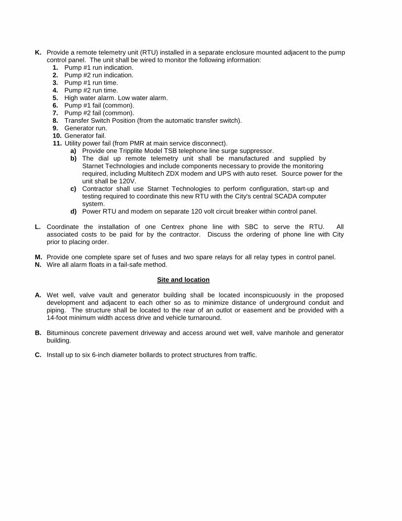
K. Provide a remote telemetry unit (RTU) installed in a separate enclosure mounted adjacent to the pump control panel. The unit shall be wired to monitor the following information:
1. Pump #1 run indication. 2. Pump #2 run indication. 3. Pump #1 run time. 4. Pump #2 run time. 5. High water alarm. Low water alarm. 6. Pump #1 fail (common). 7. Pump #2 fail (common). 8. Transfer Switch Position (from the automatic transfer switch). 9. Generator run. 10. Generator fail. 11. Utility power fail (from PMR at main service disconnect).
a) Provide one Tripplite Model TSB telephone line surge suppressor. b) The dial up remote telemetry unit shall be manufactured and supplied by
Starnet Technologies and include components necessary to provide the monitoring required, including Multitech ZDX modem and UPS with auto reset. Source power for the unit shall be 120V.
c) Contractor shall use Starnet Technologies to perform configuration, start-up and testing required to coordinate this new RTU with the City's central SCADA computer system.
d) Power RTU and modem on separate 120 volt circuit breaker within control panel.
L. Coordinate the installation of one Centrex phone line with SBC to serve the RTU. All associated costs to be paid for by the contractor. Discuss the ordering of phone line with City prior to placing order.
M. Provide one complete spare set of fuses and two spare relays for all relay types in control panel. N. Wire all alarm floats in a fail-safe method.
Site and location
A. Wet well, valve vault and generator building shall be located inconspicuously in the proposed
development and adjacent to each other so as to minimize distance of underground conduit and piping. The structure shall be located to the rear of an outlot or easement and be provided with a 14-foot minimum width access drive and vehicle turnaround.
B. Bituminous concrete pavement driveway and access around wet well, valve manhole and generator building.
C. Install up to six 6-inch diameter bollards to protect structures from traffic.

Exhibits
List of Exhibits
SAN-01 City of Oconomowoc Sanitary Sewer Manhole - Typical Opening Offset SAN-02 City of Oconomowoc Riser Detail - Flexible Riser to Flexible Main Risers Greater Than
6 Feet in Height or Mains Greater than 16 Feet Deep SAN-03 City of Oconomowoc Sanitary/Storm Manhole Cover and Assembly Neenah (R-1550)
SAN-04 City of Oconomowoc Detail of Sampling Manhole
SAN-05 City of Oconomowoc Details of Sampling and Gauging Manholes
SAN-06 City of Oconomowoc Pump Station Control Panel Door Layout
SAN-07 Manhole Vacuum Testing
LA-01 Tracer Wire Detail Layout
LA-02 Detection Wire and Location Box for Force Main Sanitary Sewer Laterals
LA-04 Detection Wire and Location Box for Building Services and Laterals
STO-06 City of Oconomowoc Typical Utility Easement

MANHOLE I OPENING / -----
'
PLAN VIEW
PROFILE VIEW
SANITARY SEWER MANHOLE TYPICAL OPENING OFFSET
EXHIBIT SAN-01 NO SCALE
u
u
0
r
GROUND SURFACE
LATERAL WHERE INCLUDED IN CONTRACT #4 BAR OR 2 x 4 16'-0"
18” MINIMUM DIAMETER FIBROUS TUBE WITH STONE CHIP BACKFILL
FOR FUTURE CONNECTION, END COMPACTED GRANULAR BACKFILL AT UPPER END OF 45o BEND AND PLUG WITH A WATERTIGHT STOPPER
APPROVED FLEXIBLE 45o BEND
DOUBLE BELL FITTING OR SPIGOT TO BELL CONNECTION
COMPACTED GRAVEL OR SPOIL BACKFILL PER PLAN
90o· LONG SWEEP ELBOW
APPROVED RISER ADAPTOR OR INSTALL SHORT NIPPLE AND PROVIDE BELL TO BELL CONTACT
APPROVED WATERTIGHT JOINTS OR SPIGOT TO BELL CONNECTION
APPROVED FLEXIBLE PRE-FABRICATED TEE OR WYE SET AT A 90o ANGLE
MINIMUM CLASS “D” CONCRETE ENCASEMENT
:;i
RISER DETAIL FLEXIBLE RISER
TO FLEXIBLE MAINS GREATER THAN 6 FEET IN HEIGHT OR MAINS
GREATER THAN 16 FEET DEEP
EXHIBIT SAN-02 NO SCALE


,.,
" n r CD
0
I
2
TOP SLAB 4'-0" I.D. PRECAST MAY BE SUBSTITUTED FOR SAMPLING MH'S ON BUILDING LATERAL 4'-0"I.D. MONOLITHIC MAY BE SUBSTITUTED FOR GAUGING MH'S ON MUNICIPAL SEWERS.
,- - - - - - - - - - --, I >
PROVIDE EXTERNAL WATERTIGHT FRAME / CHIMNEY SEAL
NEENAH R-1740B OR R-1916H OR EQUAL, FRAME AND COVER
ADJUSTING RINGS
L _j
# 6 EACH CORNER
BOTTOM FACE SECTION A-A
#5 @ 12"
C/C (E.W.)
9” #5 @ 12"
C/C (E.W.)
"
4’0” 1”
6” MONOLITHIC CONCRETE COLLAR
GROOVE WIDE & 1" DEEP IN SIDES OF BENCH 9” TRANSITION DISCHARGE OUTLET TO BE SQUARE AT MANHOLE WALL HEIGHT & WIDTH TO BE SAME AS DIAMETER OF SEWER
DETAIL OF SAMPLING AND GAUGING MANHOLE EXHIBIT SAN-05 NO SCALE


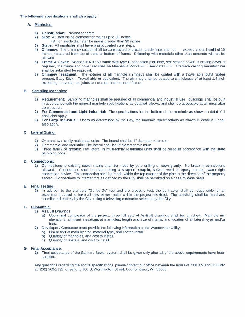
The following specifications shall also apply:
A. Manholes:
1) Construction: Precast concrete. 2) Size: 42 inch inside diameter for mains up to 30 inches. 48 inch inside diameter for mains greater than 30 inches. 3) Steps: All manholes shall have plastic coated steel steps. 4) Chimney: The chimney section shall be constructed of precast grade rings and not exceed a total height of 18
inches measured from top of cone to bottom of frame. Shimming with materials other than concrete will not be allowed.
5) Frame & Cover: Neenah # R-1550 frame with type B concealed pick hole, self sealing cover. If locking cover is required, the frame and cover set shall be Neenah # R-1916-E. See detail # 3. Alternate casting manufacturer shall be submitted for approval.
6) Chimney Treatment: The exterior of all manhole chimneys shall be coated with a trowel-able butyl rubber product, Easy Stick – Trowel-able or equivalent. The chimney shall be coated to a thickness of at least 1/4 inch extending to overlap the joints to the cone and manhole frame.
B. Sampling Manholes:
1) Requirement: Sampling manholes shall be required of all commercial and industrial use buildings, shall be built
in accordance with the general manhole specifications as detailed above, and shall be accessible at all times after construction.
2) For Commercial and Light Industrial: The specifications for the bottom of the manhole as shown in detail # 1 shall also apply.
3) For Large Industrial: Users as determined by the City, the manhole specifications as shown in detail # 2 shall also apply.
C. Lateral Sizing:
1) One and two family residential units: The lateral shall be 4" diameter minimum. 2) Commercial and Industrial: The lateral shall be 6" diameter minimum. 3) Three family or greater: The lateral in multi-family residential units shall be sized in accordance with the state
plumbing code.
D. Connections: 1) Connections to existing sewer mains shall be made by core drilling or sawing only. No break-in connections
allowed. Connections shall be made using a strap-on, snap-in, solvent weld or epoxy bonded, water tight connection device. The connection shall be made within the top quarter of the pipe in the direction of the property served. Connections to interceptors as defined by the City shall be permitted on a case by case basis.
E. Final Testing: 1) In addition to the standard "Go-No-Go" test and the pressure test, the contractor shall be responsible for all
expenses incurred to have all new sewer mains within the project televised. The televising shall be hired and coordinated entirely by the City, using a televising contractor selected by the City.
F. Submittals:
1) As Built Drawings: a) Upon final completion of the project, three full sets of As-Built drawings shall be furnished. Manhole rim
elevations, all invert elevations at manholes, length and size of mains, and location of all lateral wyes and/or tees.
2) Developer / Contractor must provide the following information to the Wastewater Utility: a) Linear feet of main by size, material type, and cost to install. b) Quantity of manholes, and cost to install. c) Quantity of laterals, and cost to install.
G. Final Acceptance:
1) Final acceptance of the Sanitary Sewer system shall be given only after all of the above requirements have been satisfied.
Any questions regarding the above specifications, please contact our office between the hours of 7:00 AM and 3:30 PM at (262) 569-2192, or send to 900 S. Worthington Street, Oconomowoc, WI. 53066.