watchguard xtm 5 series de-manufacturing … instructions ... authorization and revision history for...
TRANSCRIPT
Design for Manufacturing and Environment Document
WatchGuard Technologies. Doc #480-2535-001 Rev. A Page 1 of 21 Authorization and Revision History for this document is available in the WatchGuard ECO system
XTM 5 SeriesDe-manufacturing
Instructions
Document Number: 480-2535-001
Design for Manufacturing and Environment Document
WatchGuard Technologies. Doc #480-2535-001 Rev. A Page 2 of 21 Authorization and Revision History for this document is available in the WatchGuard ECO system
1.0 Purpose This instruction defines the de-manufacturing process for the recovery of this product family as it pertains to recycling of the major product components. 2.0 Scope This instruction applies to the following product family and family part numbers. Product Family Name Family part #’s (not necessarily inclusive) XTM 5 series XTM 505, XTM 510, XTM 520, XTM 530;
all revisions
Design for Manufacturing and Environment Document
WatchGuard Technologies. Doc #480-2535-001 Rev. A Page 3 of 21 Authorization and Revision History for this document is available in the WatchGuard ECO system
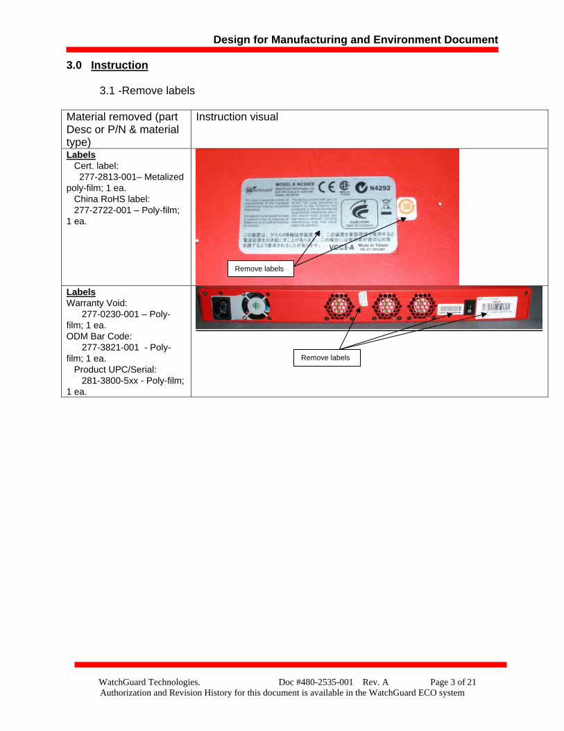
3.0 Instruction 3.1 -Remove labels
Material removed (part Desc or P/N & material type)
Instruction visual
Labels Cert. label: 277-2813-001– Metalized poly-film; 1 ea. China RoHS label: 277-2722-001 – Poly-film; 1 ea.
Labels Warranty Void: 277-0230-001 – Poly-film; 1 ea. ODM Bar Code: 277-3821-001 - Poly-film; 1 ea. Product UPC/Serial: 281-3800-5xx - Poly-film; 1 ea.
Remove labels
Remove labels
Design for Manufacturing and Environment Document
WatchGuard Technologies. Doc #480-2535-001 Rev. A Page 4 of 21 Authorization and Revision History for this document is available in the WatchGuard ECO system
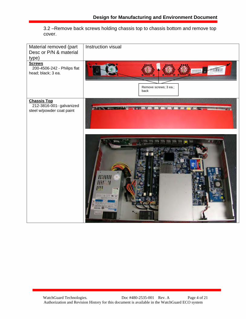
3.2 –Remove back screws holding chassis top to chassis bottom and remove top cover.
Material removed (part Desc or P/N & material type)
Instruction visual
Screws 200-4506-242 - Philips flat head; black; 3 ea.
Chassis Top 212-3816-001- galvanized steel w/powder coat paint
Remove screws; 3 ea.; back
Design for Manufacturing and Environment Document
WatchGuard Technologies. Doc #480-2535-001 Rev. A Page 5 of 21 Authorization and Revision History for this document is available in the WatchGuard ECO system
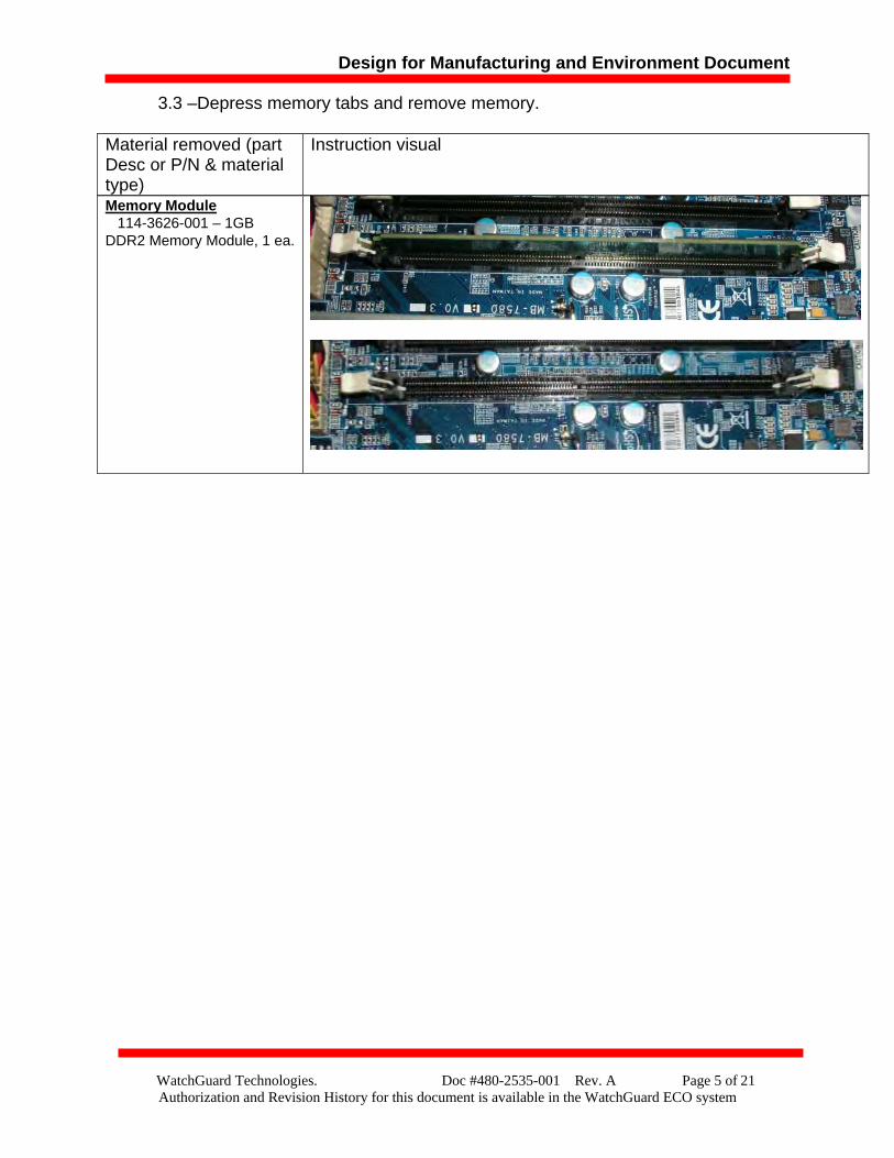
3.3 –Depress memory tabs and remove memory.
Memory Module 114-3626-001 – 1GB DDR2 Memory Module, 1 ea.
Material removed (part Desc or P/N & material type)
Instruction visual
Design for Manufacturing and Environment Document
WatchGuard Technologies. Doc #480-2535-001 Rev. A Page 6 of 21 Authorization and Revision History for this document is available in the WatchGuard ECO system
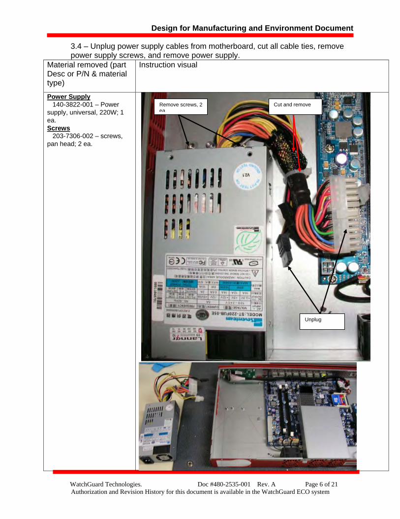
3.4 – Unplug power supply cables from motherboard, cut all cable ties, remove power supply screws, and remove power supply.
Material removed (part Desc or P/N & material type)
Instruction visual
Power Supply 140-3822-001 – Power supply, universal, 220W; 1 ea. Screws 203-7306-002 – screws, pan head; 2 ea.
Cut and remove
Unplug
Remove screws, 2 ea.

Design for Manufacturing and Environment Document
WatchGuard Technologies. Doc #480-2535-001 Rev. A Page 7 of 21 Authorization and Revision History for this document is available in the WatchGuard ECO system
3.5 – Remove screws from the power supply.
Material removed (P/N & material type)
Instruction visual
Power Supply 140-3822-001 – Power supply, universal, 220W; 1 ea. Screws Part of power supply, no WG part number– Philips flat-head; Steel/zinc; 1 ea. Bracket 212-3637-001; power supply bracket; 1 ea.
Remove screws; 2 ea.
Remove screws; 2 ea.
Remove screws; 2 ea.
Remove screws; 2 ea.; note one screw is hidden beneath void warranty label
Design for Manufacturing and Environment Document
WatchGuard Technologies. Doc #480-2535-001 Rev. A Page 8 of 21 Authorization and Revision History for this document is available in the WatchGuard ECO system
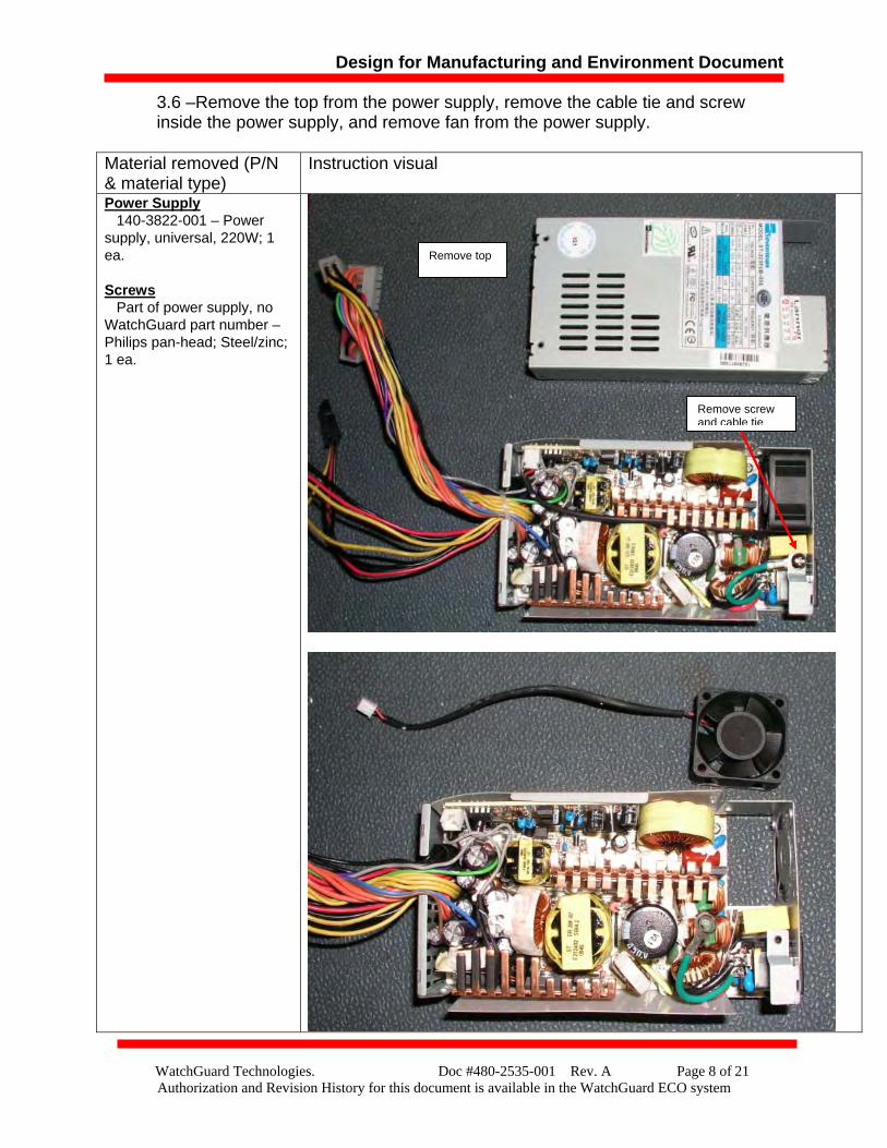
3.6 –Remove the top from the power supply, remove the cable tie and screw inside the power supply, and remove fan from the power supply.
Material removed (P/N & material type)
Instruction visual
Power Supply 140-3822-001 – Power supply, universal, 220W; 1 ea. Screws Part of power supply, no WatchGuard part number – Philips pan-head; Steel/zinc; 1 ea.
Remove top
Remove screw and cable tie
Design for Manufacturing and Environment Document
WatchGuard Technologies. Doc #480-2535-001 Rev. A Page 9 of 21 Authorization and Revision History for this document is available in the WatchGuard ECO system
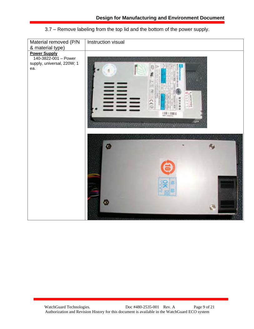
3.7 – Remove labeling from the top lid and the bottom of the power supply.
Material removed (P/N & material type)
Instruction visual
Power Supply 140-3822-001 – Power supply, universal, 220W; 1 ea.
Design for Manufacturing and Environment Document
WatchGuard Technologies. Doc #480-2535-001 Rev. A Page 10 of 21 Authorization and Revision History for this document is available in the WatchGuard ECO system
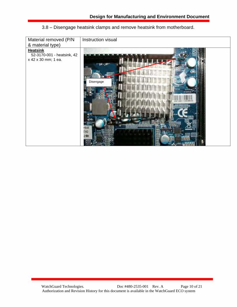
3.8 – Disengage heatsink clamps and remove heatsink from motherboard.
Material removed (P/N & material type)
Instruction visual
Heatsink 52-3170-001 - heatsink, 42 x 42 x 30 mm; 1 ea.
Disengage
Design for Manufacturing and Environment Document
WatchGuard Technologies. Doc #480-2535-001 Rev. A Page 11 of 21 Authorization and Revision History for this document is available in the WatchGuard ECO system
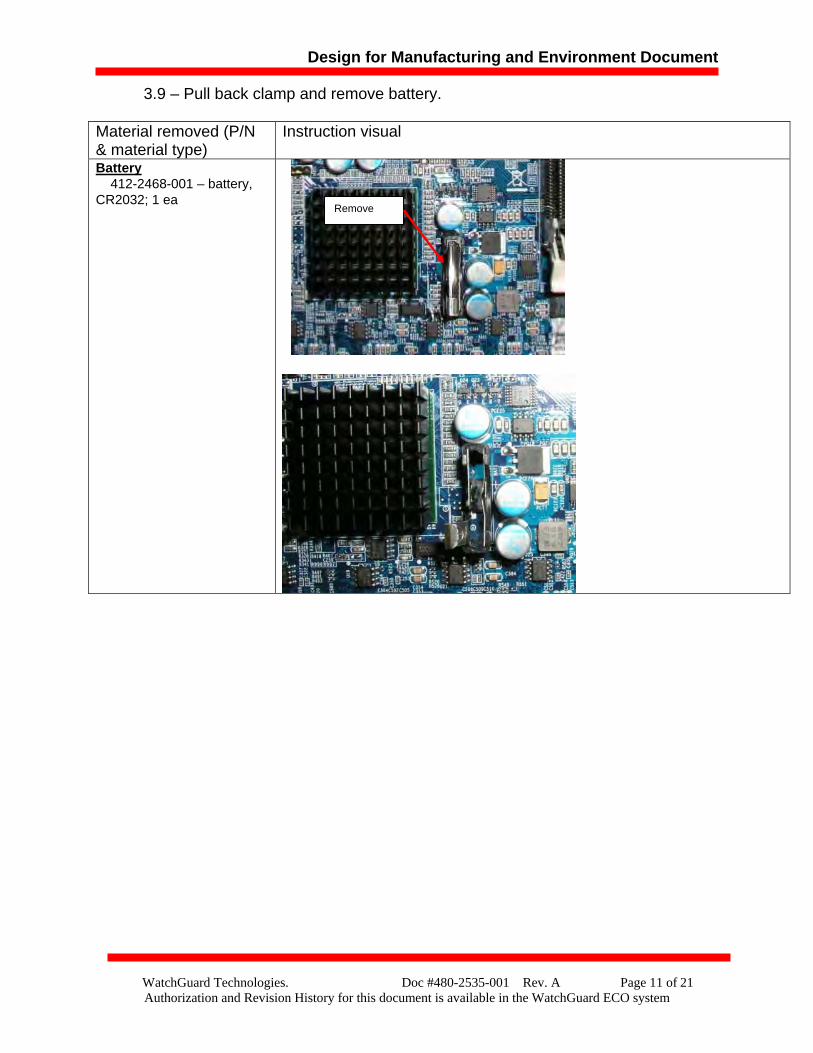
3.9 – Pull back clamp and remove battery.
Material removed (P/N & material type)
Instruction visual
Battery 412-2468-001 – battery, CR2032; 1 ea
Remove
Design for Manufacturing and Environment Document
WatchGuard Technologies. Doc #480-2535-001 Rev. A Page 12 of 21 Authorization and Revision History for this document is available in the WatchGuard ECO system
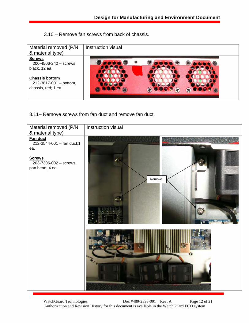
3.10 – Remove fan screws from back of chassis.
3.11– Remove screws from fan duct and remove fan duct.
Material removed (P/N & material type)
Instruction visual
Screws 200-4506-242 – screws, black, 12 ea. Chassis bottom 212-3817-001 – bottom, chassis, red; 1 ea
Material removed (P/N & material type)
Instruction visual
Fan duct 212-3544-001 – fan duct;1 ea. Screws 203-7306-002 – screws, pan head; 4 ea.
Remove
Design for Manufacturing and Environment Document
WatchGuard Technologies. Doc #480-2535-001 Rev. A Page 13 of 21 Authorization and Revision History for this document is available in the WatchGuard ECO system
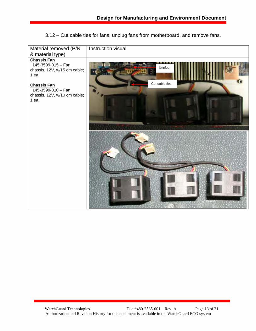
3.12 – Cut cable ties for fans, unplug fans from motherboard, and remove fans.
Material removed (P/N & material type)
Instruction visual
Chassis Fan 145-3599-015 – Fan, chassis, 12V, w/15 cm cable; 1 ea. Chassis Fan 145-3599-010 – Fan, chassis, 12V, w/10 cm cable; 1 ea.
Cut cable ties
Unplug
Design for Manufacturing and Environment Document
WatchGuard Technologies. Doc #480-2535-001 Rev. A Page 14 of 21 Authorization and Revision History for this document is available in the WatchGuard ECO system
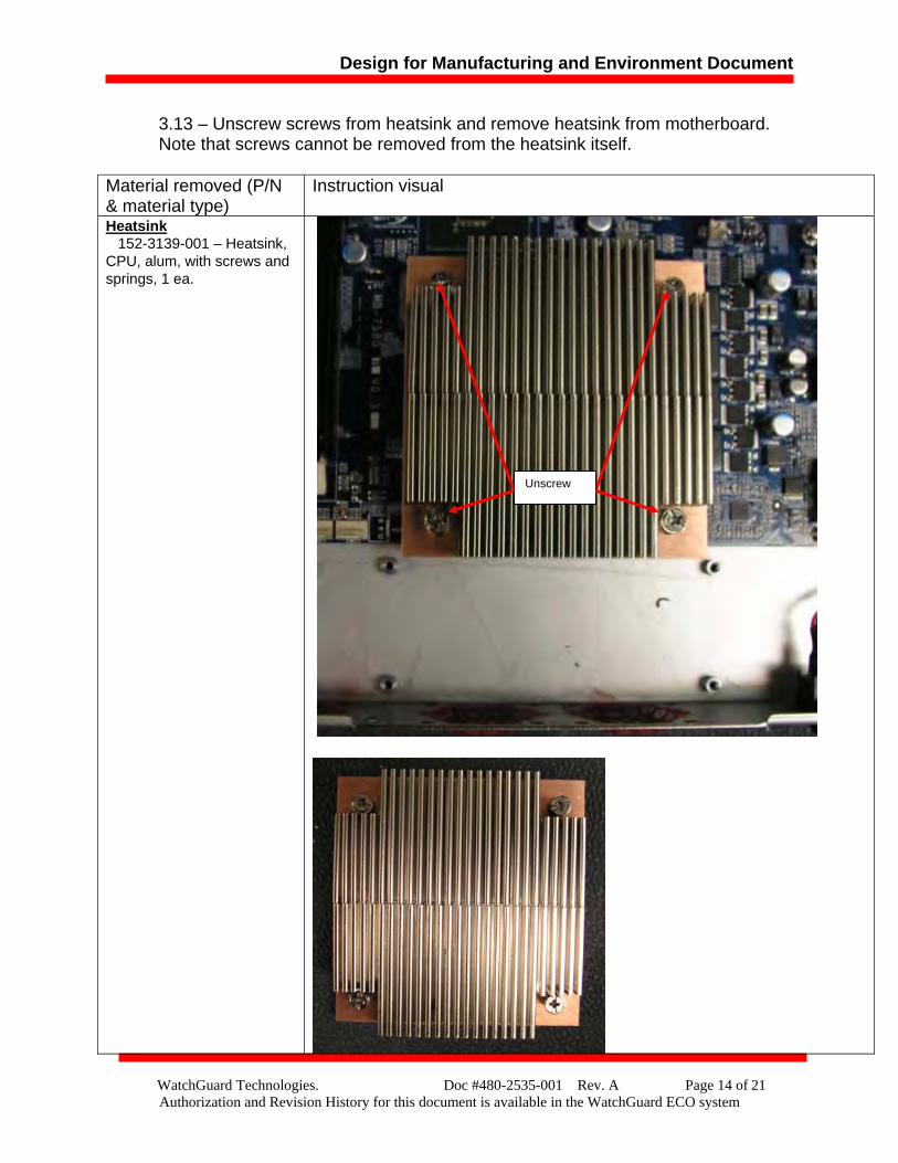
3.13 – Unscrew screws from heatsink and remove heatsink from motherboard. Note that screws cannot be removed from the heatsink itself.
Material removed (P/N & material type)
Instruction visual
Heatsink 152-3139-001 – Heatsink, CPU, alum, with screws and springs, 1 ea.
Unscrew
Design for Manufacturing and Environment Document
WatchGuard Technologies. Doc #480-2535-001 Rev. A Page 15 of 21 Authorization and Revision History for this document is available in the WatchGuard ECO system
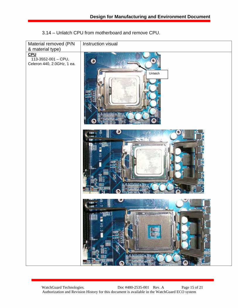
3.14 – Unlatch CPU from motherboard and remove CPU.
Material removed (P/N & material type)
Instruction visual
CPU 113-3552-001 – CPU, Celeron 440, 2.0GHz, 1 ea.
Unlatch
Design for Manufacturing and Environment Document
WatchGuard Technologies. Doc #480-2535-001 Rev. A Page 16 of 21 Authorization and Revision History for this document is available in the WatchGuard ECO system
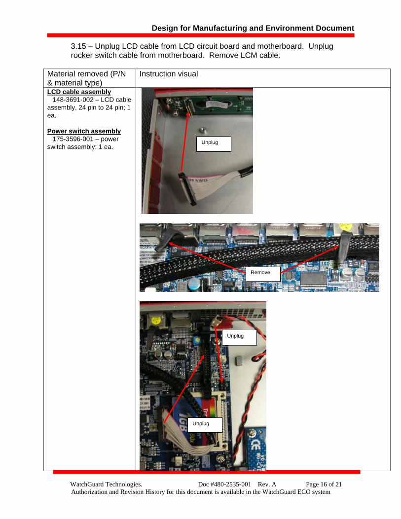
3.15 – Unplug LCD cable from LCD circuit board and motherboard. Unplug rocker switch cable from motherboard. Remove LCM cable.
Material removed (P/N & material type)
Instruction visual
LCD cable assembly 148-3691-002 – LCD cable assembly, 24 pin to 24 pin; 1 ea. Power switch assembly 175-3596-001 – power switch assembly; 1 ea.
Unplug
Remove
Unplug
Unplug
Design for Manufacturing and Environment Document
WatchGuard Technologies. Doc #480-2535-001 Rev. A Page 17 of 21 Authorization and Revision History for this document is available in the WatchGuard ECO system
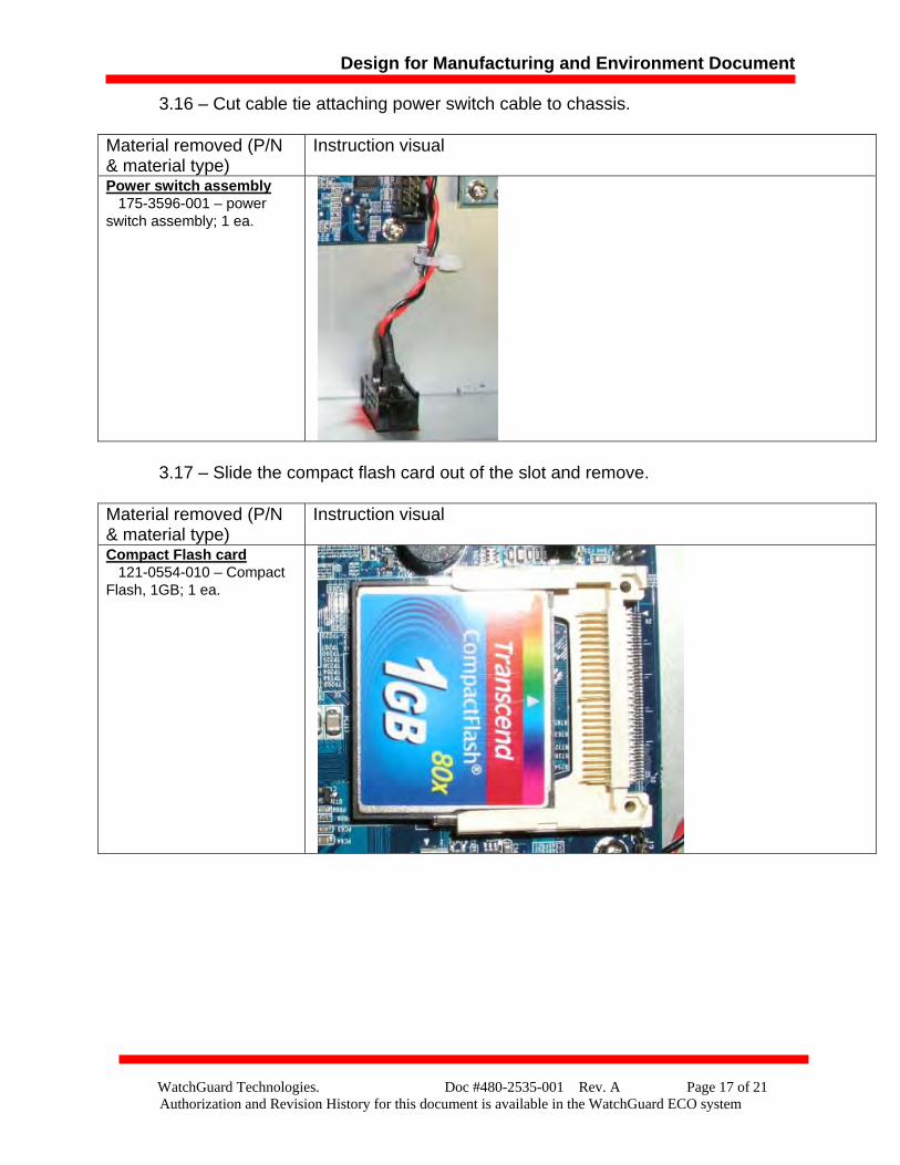
3.16 – Cut cable tie attaching power switch cable to chassis.
3.17 – Slide the compact flash card out of the slot and remove.
Material removed (P/N & material type)
Instruction visual
Power switch assembly 175-3596-001 – power switch assembly; 1 ea.
Material removed (P/N & material type)
Instruction visual
Compact Flash card 121-0554-010 – Compact Flash, 1GB; 1 ea.
Design for Manufacturing and Environment Document
WatchGuard Technologies. Doc #480-2535-001 Rev. A Page 18 of 21 Authorization and Revision History for this document is available in the WatchGuard ECO system
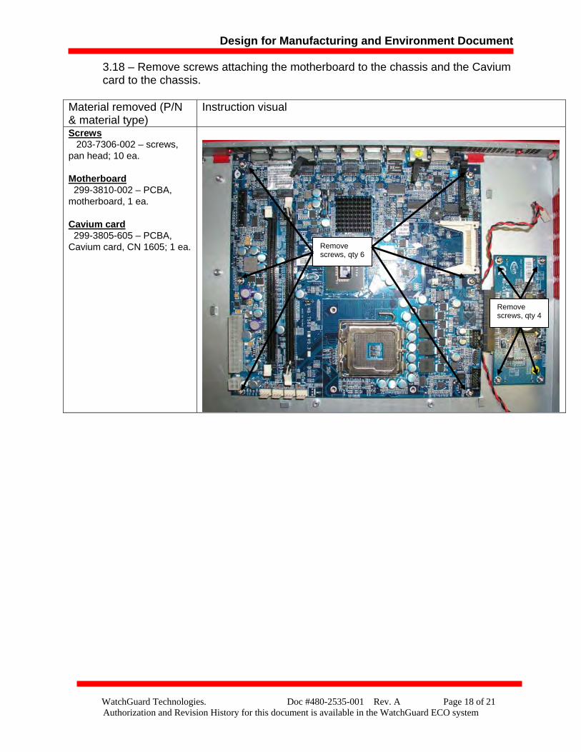
3.18 – Remove screws attaching the motherboard to the chassis and the Cavium card to the chassis.
Material removed (P/N & material type)
Instruction visual
Screws 203-7306-002 – screws, pan head; 10 ea. Motherboard 299-3810-002 – PCBA, motherboard, 1 ea. Cavium card 299-3805-605 – PCBA, Cavium card, CN 1605; 1 ea.
Remove screws, qty 6
Remove screws, qty 4
Design for Manufacturing and Environment Document
WatchGuard Technologies. Doc #480-2535-001 Rev. A Page 19 of 21 Authorization and Revision History for this document is available in the WatchGuard ECO system
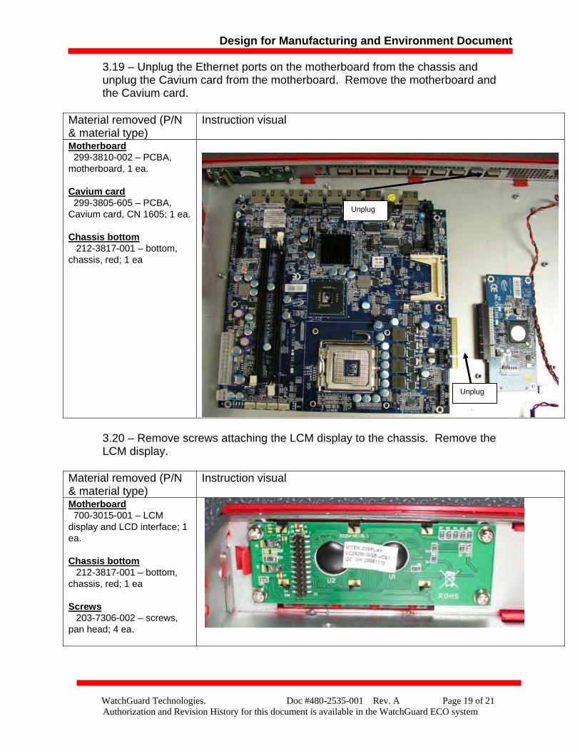
3.19 – Unplug the Ethernet ports on the motherboard from the chassis and unplug the Cavium card from the motherboard. Remove the motherboard and the Cavium card.
3.20 – Remove screws attaching the LCM display to the chassis. Remove the LCM display.
Material removed (P/N & material type)
Instruction visual
Motherboard 299-3810-002 – PCBA, motherboard, 1 ea. Cavium card 299-3805-605 – PCBA, Cavium card, CN 1605; 1 ea. Chassis bottom 212-3817-001 – bottom, chassis, red; 1 ea
Material removed (P/N & material type)
Instruction visual
Motherboard 700-3015-001 – LCM display and LCD interface; 1 ea. Chassis bottom 212-3817-001 – bottom, chassis, red; 1 ea Screws 203-7306-002 – screws, pan head; 4 ea.
Unplug
Unplug
Design for Manufacturing and Environment Document
WatchGuard Technologies. Doc #480-2535-001 Rev. A Page 20 of 21 Authorization and Revision History for this document is available in the WatchGuard ECO system
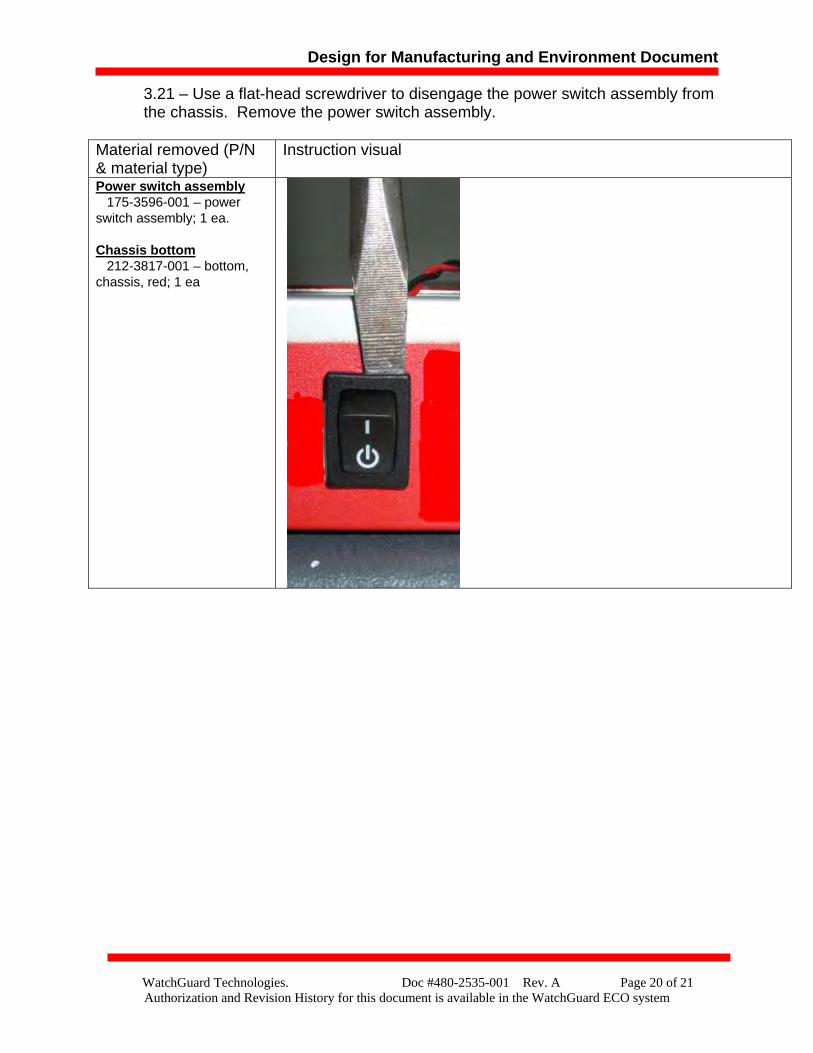
3.21 – Use a flat-head screwdriver to disengage the power switch assembly from the chassis. Remove the power switch assembly.
Material removed (P/N & material type)
Instruction visual
Power switch assembly 175-3596-001 – power switch assembly; 1 ea. Chassis bottom 212-3817-001 – bottom, chassis, red; 1 ea
Design for Manufacturing and Environment Document
WatchGuard Technologies. Doc #480-2535-001 Rev. A Page 21 of 21 Authorization and Revision History for this document is available in the WatchGuard ECO system
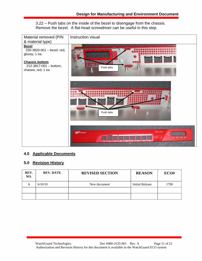
3.22 – Push tabs on the inside of the bezel to disengage from the chassis. Remove the bezel. A flat-head screwdriver can be useful in this step.
4.0 Applicable Documents
5.0 Revision History REV. NO.
REV. DATE REVISED SECTION REASON ECO#
A 6/10/10 New document Initial Release 1790
Material removed (P/N & material type)
Instruction visual
Bezel 230-3820-001 – bezel, red, glossy; 1 ea. Chassis bottom 212-3817-001 – bottom, chassis, red; 1 ea
Push tabs
Push tabs