water authority of dickson county dickson, … · wms no. 17111 1 addendum no. 1 ... probes and a...
TRANSCRIPT

WMS No. 17111 1 Addendum No. 1
WATER AUTHORITY OF DICKSON COUNTY DICKSON, TENNESSEE
FAIRVIEW WASTEWATER TREATMENT PLANT
ADDITIONS AND MODIFICATIONS (WMS #17111)
ADDENDUM NO. ONE TO THE CONTRACT DOCUMENTS
VOLUME I – CONTRACT SPECIFICATIONS The following additions and modifications shall be made to the CONTRACT SPECIFICATIONS:
1. SPECIAL CONDITIONS
(a.) Insert the attached federal wage rates to be used in conjunction with the Heavy Wage Rate determination.
(b.) Insert the attached handouts from the pre-bid conference.
2. SECTION 18D
(a.) Revise Paragraph 5.1 to read as follows:
“… Seperator (supplied under Division 18C)”
3. SECTION 19C
(a.) Revise the equipment schedule to read as follows:
Description Aeration Re-Air Post Air
Number of tanks 2 1 1
Submergence 11 ft 11 ft 7 ft
Min. number of diffusers 24 12 12
SOTR (Total-lbs-per day) 1,600 260 260
Air rate (scfm/total) 850 150 150
Max operating pressure 6 psi 6 psi 6 psi
4. SECTION 19C
(a.) Revise Paragraph 7.1.1 to read as follows:
“Control of the supplied number …”
(b.) Revise Paragraph 7.2 to read as follows:
“4. Basin DO/ORP Level”
(c.) Revise Paragraph 7.3 to read as follows:
“The enclosure shall be NEMA 12 rated. The enclosure shall be a minimum depth of 8" sized to adequately house all the components. The door shall open a minimum of 180 degrees. Devices mounted on the external surface of the enclosure shall maintain the NEMA rating of the enclosure.”
(d.) Add Paragraph 7.4 to read as follows:
“Manufacturer shall supply two (2) Dissolved Oxygen (DO) probes and two (2) Oxidation Reduction Potential (ORP) probes and a mounting kit for each probe The transmitters shall have 4-20 mA outputs for transmission of the signal to the PLC.”

WMS No. 17111 2 Addendum No. 1
5. SECTION 22
(a.) Delete Section 22 and insert the attached revised Section 22.
6. SECTION 24
(a.) Add the followings Paragraphs:
“9. Parshall Flume
9.1 Flume body shall be constructed of engineered composite fiberglass reinforced plastic and shall be molded in one piece to create a seamless corrosion barrier that is impervious to moisture.
9.2 Flume throat size shall be 9 inches.
9.3 The thickness of the walls and floor of the flume shall not be less than ¼” (6mm).
9.4 The flume shall have an inside surface that is smooth, isophthalic gelcoat of 10-20 mil thickness for UV resistance.
9.5 The surface shall be free of any exposed reinforcing fibers.
9.6 The minimum glass content shall be 30% exclusive of gelcoat surfaces.
9.7 The flume shall be reinforced with box section stiffeners down the sides and across the bottom and shall be rigidly joined at the knee to form a rigid dimensionally stable flume.
9.8 The flume shall be manufactured by Plasti-Fab or pre-approved equal. VOLUME II – CONTRACT DRAWINGS The following additions and modifications shall be made to the CONTRACT DRAWINGS:
1. SHEET P-5
(a.) Revise the annotation for modifications to the influent channel to reference Note 8.
2. SHEET P-7
(a.) Revise the top plan to delete the note regarding the aluminum checkered plate.
(b.) Revise Section P-1B to delete the note regarding the angles welded to the bottom of the plate.
(c.) Add the following General Note:
“1. Refer to Sheet S-2B for details regarding the design of the aluminum checkered plate and frame.”
3. SHEET P-12
(a.) Add the following note:
“4. Telescopic valve shall be Whipps Series 310 or preapproved equal.”
(b.) Add the following note:
“5. Scum pump shall be E-One or preapproved equal, and shall be provided with level gauges and controls as necessary to provide for a fully functional system.”
4. SHEET S-4
(a.) Revise the blower slab elevation to be 818.5 ft.
WMS No. 17111 3 Addendum No. 1
5. SHEET S-5
(a.) Add the attached detail A/S-5.
6. SHEET S-23
(a.) Revise Section 4/S-23 to change the thickness of the footing to 1’-0”.
7. SHEET S-50
(a.) Add the following note to the Typical Exterior Wall Section detail:
“Provide vented aluminum soffit. Coordinate color selection with the owner.”
WATER MANAGEMENT SERVICES, LLC
Consulting Engineers
By: ____________________________ Steven M. Jones License No. 110815 Dated: May 24, 2018
Company Name Signature Date Please acknowledge receipt of this Addendum by signing below and emailing or faxing this page back to Water Management Services, LLC at 615/366-6203. Thank you. Company Signature Date

General Decision Number: TN180113 05/04/2018 TN113
Superseded General Decision Number: TN20170113
State: Tennessee
Construction Type: Building
County: Williamson County in Tennessee.
BUILDING CONSTRUCTION PROJECTS (does not include single familyhomes or apartments up to and including 4 stories).
Note: Under Executive Order (EO) 13658, an hourly minimum wageof $10.35 for calendar year 2018 applies to all contractssubject to the Davis-Bacon Act for which the contract isawarded (and any solicitation was issued) on or after January1, 2015. If this contract is covered by the EO, the contractormust pay all workers in any classification listed on this wagedetermination at least $10.35 per hour (or the applicable wagerate listed on this wage determination, if it is higher) forall hours spent performing on the contract in calendar year2018. The EO minimum wage rate will be adjusted annually.Please note that this EO applies to the above-mentioned typesof contracts entered into by the federal government that aresubject to the Davis-Bacon Act itself, but it does not apply tocontracts subject only to the Davis-Bacon Related Acts,including those set forth at 29 CFR 5.1(a)(2)-(60). Additionalinformation on contractor requirements and worker protectionsunder the EO is available at www.dol.gov/whd/govcontracts.
Modification Number Publication Date 0 01/05/2018 1 04/27/2018 2 05/04/2018
BOIL0455-001 03/01/2018
Rates Fringes
Boilermaker....................$ 30.07 21.61----------------------------------------------------------------* BRTN0005-009 05/01/2018
Rates Fringes
BRICKLAYER.......................$ 25.62 2.28---------------------------------------------------------------- CARP0223-003 05/01/2016
Rates Fringes
CARPENTER (Including Cabinet Installation and Scaffold Builder (Excluding Drywall Hanging and Form Work)...........$ 23.95 11.36---------------------------------------------------------------- CARP1544-004 05/01/2015
Rates Fringes
https://www.wdol.gov/wdol/scafiles/davisbacon/TN113.dvb?v=2
1 of 6 5/15/2018, 9:13 AM

MILLWRIGHT.......................$ 26.02 12.11---------------------------------------------------------------- ENGI0369-008 05/01/2013
Rates Fringes
OPERATOR: Forklift..............$ 24.47 10.85OPERATOR: Grader/Blade..........$ 19.46 10.85---------------------------------------------------------------- IRON0492-008 05/01/2017
Rates Fringes
IRONWORKER, STRUCTURAL AND REINFORCING......................$ 25.31 13.82---------------------------------------------------------------- PLUM0572-006 05/01/2016
Rates Fringes
PIPEFITTER, Includes HVAC Pipe Installation................$ 36.55 16.42---------------------------------------------------------------- PLUM0572-010 05/01/2016
Rates Fringes
PLUMBER, Excludes HVAC Pipe Installation.....................$ 36.55 16.42---------------------------------------------------------------- SHEE0177-004 05/01/2017
Rates Fringes
SHEET METAL WORKER, Includes HVAC Duct and Metal Roof Installation.....................$ 26.71 13.32---------------------------------------------------------------- SUTN2009-111 09/21/2009
Rates Fringes
CARPENTER (Drywall Hanging and Form Work Only)..............$ 19.76 2.53 CEMENT MASON/CONCRETE FINISHER...$ 16.68 2.75 ELECTRICIAN, Includes Installation of Alarms...........$ 16.77 1.84 LABORER: Asphalt Raker..........$ 12.85 0.00 LABORER: Common or General......$ 12.03 0.00 LABORER: Landscape..............$ 9.60 0.80 LABORER: Mason Tender - Brick...$ 10.50 0.00 LABORER: Roof Tearoff...........$ 9.75 0.49 OPERATOR: Backhoe/Excavator/Trackhoe.......$ 16.27 0.00
https://www.wdol.gov/wdol/scafiles/davisbacon/TN113.dvb?v=2
2 of 6 5/15/2018, 9:13 AM

OPERATOR: Bobcat/Skid Steer/Skid Loader................$ 17.68 0.00 OPERATOR: Bulldozer.............$ 15.47 3.33 OPERATOR: Crane.................$ 18.80 3.28 OPERATOR: Mechanic..............$ 18.66 3.39 OPERATOR: Paver (Asphalt, Aggregate, and Concrete).........$ 14.25 0.00 OPERATOR: Roller................$ 12.83 0.00 PAINTER: Brush, Roller and Spray............................$ 13.10 0.00 ROOFER: Built up Roof...........$ 12.74 0.00 ROOFER: Rubber Roof.............$ 16.82 4.77 ROOFER: Single Ply Roof.........$ 16.50 0.32 TILE FINISHER....................$ 10.00 0.74 TRUCK DRIVER: Dump Truck........$ 12.16 0.00 TRUCK DRIVER: Material Truck....$ 12.16 1.66 TRUCK DRIVER: Pickup Truck......$ 11.70 3.92----------------------------------------------------------------
WELDERS - Receive rate prescribed for craft performingoperation to which welding is incidental.
================================================================ Note: Executive Order (EO) 13706, Establishing Paid Sick Leavefor Federal Contractors applies to all contracts subject to theDavis-Bacon Act for which the contract is awarded (and anysolicitation was issued) on or after January 1, 2017. If thiscontract is covered by the EO, the contractor must provideemployees with 1 hour of paid sick leave for every 30 hoursthey work, up to 56 hours of paid sick leave each year.Employees must be permitted to use paid sick leave for theirown illness, injury or other health-related needs, includingpreventive care; to assist a family member (or person who islike family to the employee) who is ill, injured, or has otherhealth-related needs, including preventive care; or for reasonsresulting from, or to assist a family member (or person who islike family to the employee) who is a victim of, domesticviolence, sexual assault, or stalking. Additional informationon contractor requirements and worker protections under the EOis available at www.dol.gov/whd/govcontracts.
Unlisted classifications needed for work not included withinthe scope of the classifications listed may be added afteraward only as provided in the labor standards contract clauses(29CFR 5.5 (a) (1) (ii)).
https://www.wdol.gov/wdol/scafiles/davisbacon/TN113.dvb?v=2
3 of 6 5/15/2018, 9:13 AM

----------------------------------------------------------------
The body of each wage determination lists the classificationand wage rates that have been found to be prevailing for thecited type(s) of construction in the area covered by the wagedetermination. The classifications are listed in alphabeticalorder of "identifiers" that indicate whether the particularrate is a union rate (current union negotiated rate for local),a survey rate (weighted average rate) or a union average rate(weighted union average rate).
Union Rate Identifiers
A four letter classification abbreviation identifier enclosedin dotted lines beginning with characters other than "SU" or"UAVG" denotes that the union classification and rate wereprevailing for that classification in the survey. Example:PLUM0198-005 07/01/2014. PLUM is an abbreviation identifier ofthe union which prevailed in the survey for thisclassification, which in this example would be Plumbers. 0198indicates the local union number or district council numberwhere applicable, i.e., Plumbers Local 0198. The next number,005 in the example, is an internal number used in processingthe wage determination. 07/01/2014 is the effective date of themost current negotiated rate, which in this example is July 1,2014.
Union prevailing wage rates are updated to reflect all ratechanges in the collective bargaining agreement (CBA) governingthis classification and rate.
Survey Rate Identifiers
Classifications listed under the "SU" identifier indicate thatno one rate prevailed for this classification in the survey andthe published rate is derived by computing a weighted averagerate based on all the rates reported in the survey for thatclassification. As this weighted average rate includes allrates reported in the survey, it may include both union andnon-union rates. Example: SULA2012-007 5/13/2014. SU indicatesthe rates are survey rates based on a weighted averagecalculation of rates and are not majority rates. LA indicatesthe State of Louisiana. 2012 is the year of survey on whichthese classifications and rates are based. The next number, 007in the example, is an internal number used in producing thewage determination. 5/13/2014 indicates the survey completiondate for the classifications and rates under that identifier.
Survey wage rates are not updated and remain in effect until anew survey is conducted.
Union Average Rate Identifiers
Classification(s) listed under the UAVG identifier indicatethat no single majority rate prevailed for thoseclassifications; however, 100% of the data reported for theclassifications was union data. EXAMPLE: UAVG-OH-001008/29/2014. UAVG indicates that the rate is a weighted unionaverage rate. OH indicates the state. The next number, 0010 inthe example, is an internal number used in producing the wagedetermination. 08/29/2014 indicates the survey completion date
https://www.wdol.gov/wdol/scafiles/davisbacon/TN113.dvb?v=2
4 of 6 5/15/2018, 9:13 AM

for the classifications and rates under that identifier.
A UAVG rate will be updated once a year, usually in January ofeach year, to reflect a weighted average of the currentnegotiated/CBA rate of the union locals from which the rate isbased.
----------------------------------------------------------------
WAGE DETERMINATION APPEALS PROCESS
1.) Has there been an initial decision in the matter? This canbe:
* an existing published wage determination* a survey underlying a wage determination* a Wage and Hour Division letter setting forth a position on a wage determination matter* a conformance (additional classification and rate) ruling
On survey related matters, initial contact, including requestsfor summaries of surveys, should be with the Wage and HourRegional Office for the area in which the survey was conductedbecause those Regional Offices have responsibility for theDavis-Bacon survey program. If the response from this initialcontact is not satisfactory, then the process described in 2.)and 3.) should be followed.
With regard to any other matter not yet ripe for the formalprocess described here, initial contact should be with theBranch of Construction Wage Determinations. Write to:
Branch of Construction Wage Determinations Wage and Hour Division U.S. Department of Labor 200 Constitution Avenue, N.W. Washington, DC 20210
2.) If the answer to the question in 1.) is yes, then aninterested party (those affected by the action) can requestreview and reconsideration from the Wage and Hour Administrator(See 29 CFR Part 1.8 and 29 CFR Part 7). Write to:
Wage and Hour Administrator U.S. Department of Labor 200 Constitution Avenue, N.W. Washington, DC 20210
The request should be accompanied by a full statement of theinterested party's position and by any information (wagepayment data, project description, area practice material,etc.) that the requestor considers relevant to the issue.
3.) If the decision of the Administrator is not favorable, aninterested party may appeal directly to the AdministrativeReview Board (formerly the Wage Appeals Board). Write to:
Administrative Review Board U.S. Department of Labor 200 Constitution Avenue, N.W.
https://www.wdol.gov/wdol/scafiles/davisbacon/TN113.dvb?v=2
5 of 6 5/15/2018, 9:13 AM

Washington, DC 20210
4.) All decisions by the Administrative Review Board are final.
================================================================
END OF GENERAL DECISION
https://www.wdol.gov/wdol/scafiles/davisbacon/TN113.dvb?v=2
6 of 6 5/15/2018, 9:13 AM
Fairview Wastewater Treatment Plant Additions and Modifications Project (WMS #17111)
Construction Activities Critical Path
The scope of this project involves the additions and modifications to the Fairview Wastewater Treatment Plant including the addition of a new headworks structure, anaerobic and anoxic basins, 40-foot diameter clarifier, refurbishment of the existing clarifiers, installation of jet aeration equipment into an existing ditch, UV, recycle pumps, poured in place concrete construction, together with all required instrumentation, piping, equipment, plumbing, heating, ventilation, electrical, grading, demolition, and appurtenances as required.
The Contractor shall submit a detailed Sequence of Construction for review and approval prior to the start of work. The submittal shall include all planned shutdowns, the duration of the shutdown, and the plan for providing full treatment during construction. The Sequence of Construction shall be integrated with the project schedule. The Sequence of Construction must meet the following minimum requirements:
• Full biological treatment, solids removal and disinfection must be provided at all times during construction
• New headworks must be in operation prior to shutdown of existing headworks • New process train must be in operation prior to shutdown of existing oxidation
ditch • New UV system must be in operation prior to shutdown of existing disinfection
system • New facilities shall be in operation for at least seven (7) days without operational
issues prior to shutdown of corresponding existing facilities. • Contractor to provide all temporary piping and pumping necessary to maintain
treatment during construction
Contractor shall provide a minimum 72 hour notice prior to requiring any shutdown of the existing facilities. Short shutdowns of less than 4 hours can be accomplished by shutting down the influent pump station during low flow periods. For longer shutdowns, the contractor shall submit a plan for review and approval by the engineer detailing the need for the shutdown and the anticipated amount of time that is needed.
The following is a suggested sequence of construction. The final Sequence of Construction is the responsibility of the Contractor.

Phase I
The Phase I components depicted in the contract drawings show the minimum facilities required to complete a shutdown of the existing facilities in order to dewater and clean the oxidation ditch.
This phase includes minimum construction of the following components:
• New headworks • Anaerobic tanks • Anoxic/Aerobic tanks • Electrical building • Secondary anoxic and re/air basins • Mixed liquor control structure • Plant water system • All associated piping • Meter vault for RAS and nitrified recycle lines
Following construction of these facilities, the contractor shall transfer mixed liquor from the oxidation ditch into the new anaerobic/anoxic tankage. Influent flow shall be split between the new and existing facilities until stable operation of the Phase I facilities is achieved upon which time all flow will be diverted to the newly constructed facilities.
Phase II
After bringing the Phase I facilities online, the existing oxidation ditch will be drained and cleaned. While drained, jet aeration will be installed in both the inner and outer ring of the existing ditch. The existing disc aeration in the outer ring will be rehabilitated and additional discs will be added.
As part of Phase II construction, the following facilities will be constructed:
• Nitrified recycle pump station • 40’ clarifier and associated piping • Post aeration / U.V. disinfection and associated piping • All associated piping • Jet aeration within the existing oxidation ditch • Rehabilitation of Disc aeration

WMS No. 17111 (Add #1)
TABLE OF CONTENTS
FOR
DIVISION 22
PUMPS AND DRIVES SECTION PAGE 22A GENERAL PUMP REQUIREMENTS 1-2 22B SUBMERSIBLE PUMPS 1-4 22C PUMP CONTROLLER 1-3

WMS No. 17111 22A-1 General Pump Requirements (Add #1)
PUMPS AND DRIVES
SECTION 22A
GENERAL PUMP REQUIREMENTS
1. GENERAL 1.1 Furnish and install the pumps, drives and related accessories required for this project,
unless specified under other sections. 1.2 See Section 1E for other requirements relating to furnishing and installing equipment
items. 1.3 To reduce maintenance expense, pumps of the same type shall be supplied by the
same manufacturer insofar as possible. 2. TESTS 2.1 Furnish six copies of certified curves, based on pumping clear water, showing the
capacity, efficiency and brake horsepower for each pump furnished, and for maximum and minimum speeds where applicable. Curves shall be derived from shop tests performed by the manufacturer in accordance with the standards of the hydraulic institute.
2.2 After installation, conduct field tests to demonstrate that capacities and operating characteristics specified are developed.
2.3 Each motor shall be given a routine test at the factory to assure conformance to design standards and limits, and freedom from mechanical and electrical defects.
3. SUBMITTALS 3.1 Shop drawings shall be submitted in accordance with Section 1C. 3.2 Shop drawings shall include details and assembly plans, including parts lists and
complete material specifications for each type and size of pump furnished. 3.3 Shop drawings for motors submitted for approval shall include the following motor data:
1. Manufacturer 2. Nameplate rated horsepower 3. Rated voltage 4. Full load rpm 5. Full load current 6. Full load power factor (20 hp and larger) 7. NEMA design letter 8. NEC code letter or inrush current 9. Insulation class 10. Service factor
4. NAMEPLATES 4.1 Brass or stainless steel nameplates shall be attached to each pump stamped with the
manufacturer’s name, capacity, head in feet, rpm, and identification number. 5. MOTORS 5.1 Pump motors shall be non-overloading throughout its entire performance curve, from
shut-off to run-out.
WMS No. 17111 22A-2 General Pump Requirements (Add #1)
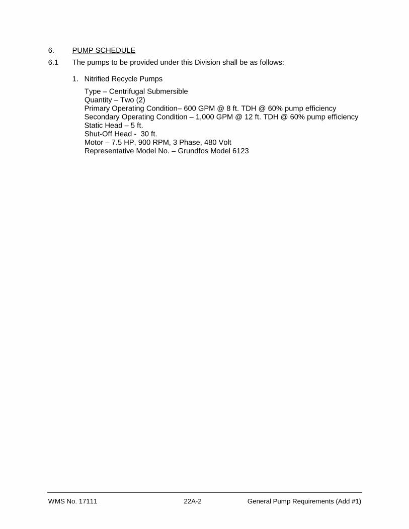
6. PUMP SCHEDULE 6.1 The pumps to be provided under this Division shall be as follows:
1. Nitrified Recycle Pumps
Type – Centrifugal Submersible Quantity – Two (2)
Primary Operating Condition – 600 GPM @ 8 ft. TDH @ 60% pump efficiency Secondary Operating Condition – 1,000 GPM @ 12 ft. TDH @ 60% pump efficiency
Static Head – 5 ft. Shut-Off Head - 30 ft. Motor – 7.5 HP, 900 RPM, 3 Phase, 480 Volt Representative Model No. – Grundfos Model 6123

WMS No. 17111 22B-1 Submersible Pumps (Add #1)
PUMPS AND DRIVES
SECTION 22B
SUBMERSIBLE PUMPS 1. GENERAL
1.1 Furnish and install submersible pumps as indicated on the drawings. Each pump shall be complete with all accessories, controls and appurtenances as shown in the plans and specified herein or as required for a complete operating system. Each Pumping Unit shall be rated for handling unscreened sewage wastewater
1.2 The design shall be such that the pumping units will be automatically connected to the discharge piping when lowered into place on the discharge connection. The pump shall be easily removable for inspection or service without the need for removal of nuts, bolts or other fasteners and without the need for personnel to enter the wet-well.
1.3 See Section 1F for other requirements relating to furnishing and installing equipment items.
1.4 Submit shop drawings and equipment data as specified in Section 1C.
1.5 All components described in this section shall be supplied by the pump manufacturer.
1.6 Pumps shall be as manufactured by Grundfos or pre-approved equal. 2. PUMP
2.1 The Submersible Pumping Units shall be self-contained, integral pump/motor units designed to operate at continuous full load in a partially or completely submerged condition without the need for any external cooling devices such as water jackets.
2.3 Bearings shall be specifically selected to carry all radial and axial loads imposed by the pump and motor. Bearings shall be rated to provide a minimum L10 Bearing Life of 25,000 hours at any design operating point within the allowable operating region (limit lines). Bearing selection shall limit the bearing temperature rise to a maximum of 60° C under full load operation.
2.3 All bearings shall be permanently lubricated with a premium moisture resistant grease containing rust inhibitors and shall be suitable for operation over a temperature range of -25° C to +120° C. The bearings shall not require any additional or periodic lubrication. All bearings shall be commercially available from third party sources other than the pump/motor manufacturer.
2.4 Two independent, tandem mounted, mechanical seals shall be provided in the oil filled housing to isolate and protect the air-filled motor from the pumped media. The oil reservoir shall act as a barrier to trap moisture and provide sufficient time for a planned shutdown in the event of an outer seal failure.
2.5 The inner mechanical seal shall be constructed with a solid block carbon rotating seal face and a solid block silicon carbide stationary seal face.
2.6 The outer mechanical seal shall be constructed with a solid block silicon carbide rotating seal face and a solid block silicon carbide stationary face. The outer mechanical seal shall be located in a recessed housing outside the main flow path of the pump to avoid damage

WMS No. 17111 22B-2 Submersible Pumps (Add #1)
2.7 All metal components of the inner and outer seals shall be AISI 316 stainless steel. All elastomers of both inner and outer seals shall be of Viton® material.. Mechanical seals that employ sprayed or laminated seal faces shall neither be considered equal, nor shall they be acceptable.
2.8 Mechanical seals shall be readily and commercially available from third party sources other than the pump and motor manufacturer, their agents, dealers and/or distributors. Mechanical Seals shall be Type 21 or approved equivalent.
2.9 The pumps shall be designed for installation utilizing a base discharge elbow that shall meet the slide bracket by method of a three point, wedged engagement that is uniquely designed to match the volute flange to the stationary elbow to eliminate head losses. The discharge elbow shall be designed to carry the full weight of the pump, motor and discharge piping. The slide bracket shall be of heavy-duty cast iron construction.
2.10 Guide rail mounting brackets shall be furnished to stabilize the guide rails for installation in deep wet wells. Brackets shall be spaced at proper intervals to provide rigidity and parallelism. The brackets shall be designed to fit exactly into the pipes for which they were designed. Adjustable and/or flexible brackets designed to fit a variety of guide rail pipe sizes shall not be acceptable. Mounting brackets shall be of stainless steel construction.
2.11 The pump casing, impeller, motor housing and stationary base elbow shall be manufactured of close-grained cast iron, ASTM A48, Class 30.
2.12 The pump casing shall be of the volute design, of one piece construction, having centerline discharge to minimize clogging or flow interference, and to provide the proper weight distribution for use with the Easy-Lift disconnect system.
2.13 The impeller shall be of a multi or single-vaned, fully shrouded enclosed design and shall have large passages to provide smooth flow transition and unimpeded passage of large spherical solids. All impellers shall be statically and dynamically balanced to ISO 1940, G.6.3. Solids passing capability of the impeller offered shall be clearly indicated on the manufacturer’s performance curve.
2.14 The impeller shall contain replaceable stainless steel wear ring shall be provided on the impeller inlet to reduce the effects of abrasive wear and provide the ability to renew the running clearance.
2.15 The volute suction shall contain a replaceable stainless steel wear ring to match the impeller wear ring.
2.16 All external casting surfaces of the pump/motor coming into contact with the pumped liquid shall have a surface cleanliness equal to that of a SSPC-SP3 process prior to being factory protected by one (1) coat of an environmentally-safe machinery enamel coating with a high solids content.
2.17 All external hardware including nameplates on the pump/motor shall be 300 Series stainless steel.
3. MOTOR
3.1 The air-filled motor shall be cooled by an adequately sized motor frame which shall conform to the latest applicable requirements of NEMA, IEEE. ANSI and NEC standards and shall meet the latest design standards of a Totally Enclosed Non-Ventilated NEMA frame motor.

WMS No. 17111 22B-3 Submersible Pumps (Add #1)
3.2 Heat transfer shall be accomplished by convection through the stator-housing wall to the surrounding media. Designs which incorporate cooling jackets and in particular, designs which rely on circulation of the pumped sewage or externally sourced water for cooling, are not considered equal to the equipment described in this specification and shall not be acceptable.
3.3 The submersible motor enclosure including frame, end brackets, flanges and cap assembly shall be constructed of close-grained cast iron, ASTM A-48, Class 30 or better.
3.4 The top end bracket shall be fitted with a lifting bail and shall be capable of supporting four (4) times the combined weight of the pump and motor.
3.5 All mating fits on the motor frame shall have rabbet joints with large overlap as well as o-ring seals to provide for a watertight seal. O-rings shall be Buna-N.
3.6 The one-piece motor/pump shaft shall be constructed of stainless steel and shall be precision machined to ensure proper tolerances at all contact points. The entire rotating assembly shall be designed with sufficient rigidity for minimal shaft deflection at extreme pump operating conditions.
3.7 The motor rotor shall be of squirrel-cage design and constructed of die cast aluminum, fabricated copper or their respective alloys. The rotor shall have an interference fit to the shaft and the rotating assembly shall be dynamically balanced to ISO 1940, G.6.3. Balance weights, if required, shall be secured to the rotor resistance ring or rotor fins. Machine screws or nuts and bolts used to attach balance weights are specifically prohibited.
3.8 The submersible motors shall successfully operate under power supply variations per NEMA MG1-14.30. Motors shall be NEMA Design B with torque and starting current in accordance with NEMA MG1-12.
The submersible motors shall be of an air-filled, high efficiency design and shall be rated for continuous full load operation. The motor construction shall be of explosion proof, TENV-TEXP design and capable of being certified for use in Class 1, Division 1, Groups C & D hazardous locations by Factory Mutual Research Corp. (F.M.). Motors shall be capable of withstanding up to 15 starts per hour and shall have a minimum 1.15 Service Factor at 40° C ambient.
3.9 Stators shall be solid copper wound and shall be press fitted into the stator housing for true positive alignment and efficient heat transfer. The motor insulation system shall be Class H minimum (Class F for 140 frame), utilizing materials and insulation systems evaluated and certified with IEEE 117 classification tests. The entire wound stator assembly shall receive a minimum of two (2) coats of insulating varnish utilizing a dip and bake process.
3.10 The power and control cable entry system shall be designed to provide a positive, leak-free seal to prevent liquid from entering the air filled motor housing. The design shall incorporate provisions that prevent moisture from wicking through the cable assembly even in the event the cable jacket has been punctured. All cable shall be type SEOW-A or better and U.L. Listed for the intended submersible service.
3.11 Units above 1-1/2 HP shall be designed with separate power and control cables to prevent false sensor warnings. The power and control cable entry into the lead connection chamber shall be epoxy encapsulated for positive moisture sealing. For frame size 180 and above, the power and control cables shall be unitized modular assemblies permitting individual repair or replacement. Each modular cable unit shall

WMS No. 17111 22B-4 Submersible Pumps (Add #1)
include a cast iron connector body with flared inlet to protect against cable damage due to bending or flexing at the entry point. Each cable unit shall include both epoxy seal and a Neoprene sealing grommet. A sleeve/spacer shall be provided to isolate the epoxy from the connector body and facilitate easy removal and replacement of the sealing compound. Assembly of cable components and grommet tensioning shall be accomplished by a precision snap-ring connection to prevent cable damage or leakage due to under or over compression. The system shall permit the use of factory supplied epoxy or other commercial sealants for field repair. Cable strain relief shall be independent of the epoxy seal. Individual cable units shall be designed to permit repair or rebuilding independent of the motor.
3.12 Each cap & cable assembly shall include a modular design rail-mounted terminal block system with individual terminal units for connection of each power and control lead. The terminal block system shall utilize standard non-proprietary commercial components.
3.13 Three (3) normally closed, automatic reset thermostats connected in series shall be embedded in adjoining phases of the stator windings. The thermostats shall be connected to safely shut down the motor upon opening. MOISTURE DETECTION SYSTEM
3.13 A dual (2) probe moisture sensing system shall detect the entrance of moisture and provide an alarm. The moisture detection system shall be designed to detect the entrance of moisture in the stator and lower oil seal housing. The use of single probe or float switch type sensor systems shall not be acceptable. The moisture sensing probe leads shall terminate at a conductance relay located in the control panel, which shall provide an alarm in the event of moisture intrusion. The sensing relay (if not specifically ordered from the pump manufacturer) shall be approved by the pump/motor manufacturer.
4. PUMP TESTS
4.1 The pump manufacturer shall perform the following inspections and tests on each pump before shipment from factory:
1. Impeller, motor rating and electrical connections shall first be checked for compliance to the customer's purchase order.
2. A motor and cable insulation test for moisture content or insulation defects shall be made.
3. Prior to submergence, the pump shall be run dry to establish correct rotation and mechanical integrity.
4. The pump shall be run submerged in water to minimum of six (6) feet.
5. After operational test No. 4, the insulation test (No. 2) is to be performed again.
4.2 A written report stating the foregoing steps have been done shall be supplied with each pump at the time of shipment
WMS No. 17111 22C-1 Pump Controls (Add #1)
PUMPS AND DRIVES
SECTION 22C
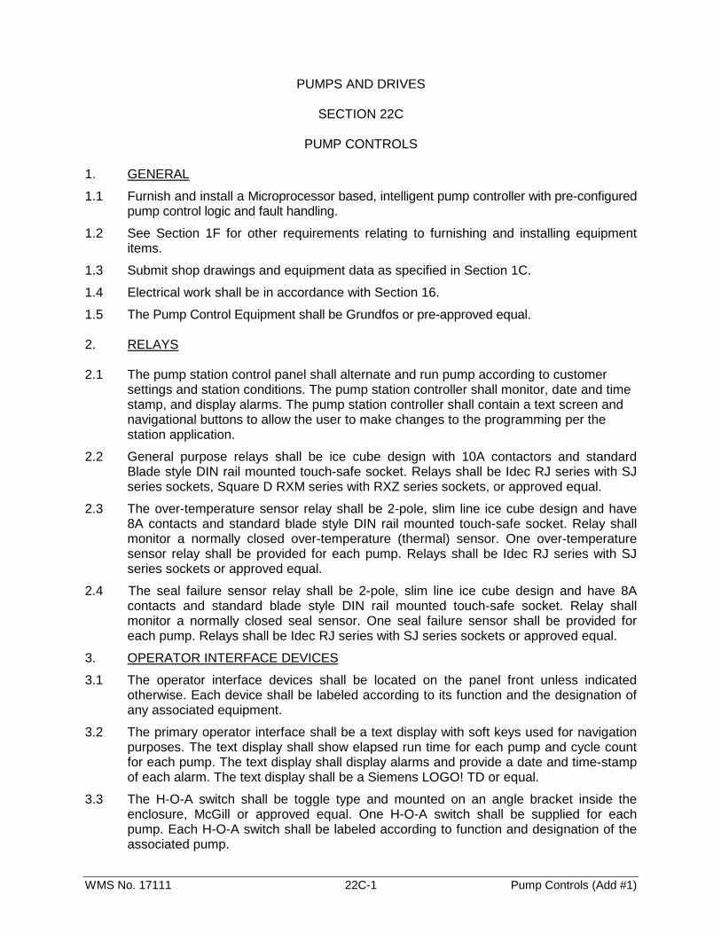
PUMP CONTROLS 1. GENERAL
1.1 Furnish and install a Microprocessor based, intelligent pump controller with pre-configured pump control logic and fault handling.
1.2 See Section 1F for other requirements relating to furnishing and installing equipment items.
1.3 Submit shop drawings and equipment data as specified in Section 1C.
1.4 Electrical work shall be in accordance with Section 16.
1.5 The Pump Control Equipment shall be Grundfos or pre-approved equal. 2. RELAYS 2.1 The pump station control panel shall alternate and run pump according to customer
settings and station conditions. The pump station controller shall monitor, date and time stamp, and display alarms. The pump station controller shall contain a text screen and navigational buttons to allow the user to make changes to the programming per the station application.
2.2 General purpose relays shall be ice cube design with 10A contactors and standard Blade style DIN rail mounted touch-safe socket. Relays shall be Idec RJ series with SJ series sockets, Square D RXM series with RXZ series sockets, or approved equal.
2.3 The over-temperature sensor relay shall be 2-pole, slim line ice cube design and have 8A contacts and standard blade style DIN rail mounted touch-safe socket. Relay shall monitor a normally closed over-temperature (thermal) sensor. One over-temperature sensor relay shall be provided for each pump. Relays shall be Idec RJ series with SJ series sockets or approved equal.
2.4 The seal failure sensor relay shall be 2-pole, slim line ice cube design and have 8A contacts and standard blade style DIN rail mounted touch-safe socket. Relay shall monitor a normally closed seal sensor. One seal failure sensor shall be provided for each pump. Relays shall be Idec RJ series with SJ series sockets or approved equal.
3. OPERATOR INTERFACE DEVICES
3.1 The operator interface devices shall be located on the panel front unless indicated otherwise. Each device shall be labeled according to its function and the designation of any associated equipment.
3.2 The primary operator interface shall be a text display with soft keys used for navigation purposes. The text display shall show elapsed run time for each pump and cycle count for each pump. The text display shall display alarms and provide a date and time-stamp of each alarm. The text display shall be a Siemens LOGO! TD or equal.
3.3 The H-O-A switch shall be toggle type and mounted on an angle bracket inside the enclosure, McGill or approved equal. One H-O-A switch shall be supplied for each pump. Each H-O-A switch shall be labeled according to function and designation of the associated pump.
WMS No. 17111 22C-2 Pump Controls (Add #1)
3.4 The pump running pilot light shall be UL Type 4x, with 120 VAC green LED and green lens, Square D XB5 series 22mm or approved equal. One pump running pilot light shall be supplied for each pump. Each pump running pilot light shall be labeled according to function and designation of the associated pump. The pump running pilot light shall be illuminated when the associated pump starter is engaged.
3.5 The pump fault indication shall be listed on the HMI keypad.
3.6 The elapsed time monitor shall be monitored for each pump and displayed by selection menu from the HMI operator interface. Within the HMI operator interface screens, each elapsed time monitor shall be labeled according to function and designation of the associated pump. The elapsed time meter shall start timing when the associated pump starter is engaged.
3.7 The cycle counter shall be monitored for each pump and displayed by selection menu from the HMI operator interface. Each cycle counter shall be labeled according to function and designation of the associated pump. The cycle counter shall advance one digit each time the associated pump starter is engaged.
3.8 The flashing alarm beacon shall be a 120 Volt, 25 watt, UL listed Type 4x, shatter resistant flashing beacon with red lens, Ingram LRX Series or approved equal. The flashing alarm beacon shall function when a high level condition is present.
3.9 The audible alarm shall be a 120 volt, 95 dB at 2 feet, include a gasket and be UL listed Type 4X, Floyd Bell MW-09 Series or approved equal. The audible alarm shall output a warble tone. The audible alarm shall include a silence and test switch.
3.10 External or flush mounted devices shall be labeled with engraved laminated phenolic nameplates secured with permanent pressure sensitive adhesive. Internal labels shall be white polyester permanent pressure sensitive tape printed with black thermal transfer lettering.
3.11 Relays shall provide for dry contacts for high level alarm, pump fail alarm and power fail alarm. Each pump shall be indicated with a unique dry contact. Contacts shall include common, open and closed connections.
4. ENCLOSURE
4.1 NEMA 4X - 304 Stainless
4.2 The enclosure shall be a NEMA 4X rated enclosure manufactured from 304 stainless steel. The enclosure shall be a minimum depth of 8" sized to adequately house all the components. The door gasket shall be foamed in place rubber composition and shall assure a positive weatherproof seal. The door shall open a minimum of 180 degrees. Devices mounted on the external surface of the enclosure shall maintain the NEMA rating of the enclosure.
4.3 A polished aluminum dead front shall be mounted on a continuous aircraft type hinge, shall contain cutouts for mounted equipment, and shall provide protection of personnel from live internal wiring. Cutouts for breaker handles shall be provided to allow operation of breakers without entering the compartment.
4.4 All control switches, indicator pilot lights, elapsed time meters, duplex receptacle and other operational devices shall be mounted on the external surface of the dead front. The dead front shall open a minimum of 150 degrees to allow access to equipment for maintenance. A 3/4" break shall be formed around the perimeter of the dead front to provide rigidity. Devices mounted on the external surface of the enclosure shall maintain the rating of the enclosure.

WMS No. 17111 22C-3 Pump Controls (Add #1)
4.5 The back plate shall be manufactured of 12 gauge sheet steel and be finished with a primer coat and two [2] coats of baked on white enamel. All hardware mounted to the sub panel shall be accomplished with machine thread tapped holes. Sheet metal screws are not acceptable. All devices shall be permanently identified with engraved legends. All hardware mounted to the sub panel shall be accomplished with machine thread tapped holes. Sheet metal screws are not acceptable. All devices shall be permanently identified with engraved legends.
5. LEVEL SENSING EQUIPMENT
5.1 Provide and install float type level switches. Float switches shall be provided and wired to provide input to the controller for low level cut off, for the pumps.
5.2 Float switches shall be ENM with mechanically activated switch. Float switches have an internal weight and are housed in a chemical-resistant polypropylene casing.
5.3 Provide stainless steel hatch mounted hanger bracket suitable to secure and facilitate adjustment of all float switches.

TOP WALL
EL. 827.50
TOP SLAB
EL. 825.0
TO TOP OF WALLEPOXY BOLTED
(MATCH EXISTING)CLOSURE PIECE
ALUM. GUARDRAIL
CENTERED ON WALLTHREE SIDES
WATERSTOPSYKNO-FLEX
EACH FACE, EACH SIDE(4) #5x1’-6" (MIN. 6" EMBED.)
WITH EPOXY DOWELS(NON-SHRINK MIX)
CLOSURE WALL12" THICK CONCRETE
2’-
6"
1’-0" 1’-6" 1’-0"
DETAIL "A/S-5"CHANNEL MODIFICATION
WALLOXIDATION DITCH
EXISTING