water cooling towers - iso-iran.ir 4485-4-1996.pdf · british standard bs4485-4: 1996 water cooling...
TRANSCRIPT
BRITISH STANDARD BS 4485-4:1996
Water cooling towers —
Part 4: Code of practice for structural design and construction
ICS 27.100:91.080
Confirmed December 2011

BS 4485-4:1996
This British Standard, having been prepared under the direction of the Engineering Sector Board, was published under the authority of the Standards Board and comes into effect on15 August 1996
© BSI 07-1999
The following BSI references relate to the work on this standard:Committee reference B/525/15Draft for comment 92/17117 DC
ISBN 0 580 25544 1
Committees responsible for this British Standard
The preparation of this British Standard was entrusted to Technical Committee B/525/15, Cooling towers, upon which the following bodies were represented:
Association of Consulting EngineersBEAMA Ltd.Concrete SocietyElectricity AssociationEngineering Employers’ FederationFederation of Civil Engineering ContractorsHealth and Safety ExecutiveHevac AssociationIndustrial Water SocietyInstitution of Chemical EngineersInstitution of Civil EngineersInstitution of Structural EngineersProcess Plant AssociationCo-opted member
Amendments issued since publication
Amd. No. Date Comments
BS 4485-4:1996
© BSI 07-1999 i
Contents
PageCommittees responsible Inside front coverForeword iiSection 1. General1.1 Scope 11.2 References 11.3 Definitions 11.4 Symbols 31.5 Materials and workmanship 31.6 Packing support structures 61.7 Packings, water distribution systems, eliminators and cladding 81.8 Cooling tower fittings 91.9 Water retaining structures 91.10 Foundations and bases 10Section 2. Hyperboloidal cooling towers (type 1 towers)2.1 Basis of design 112.2 Loading 112.3 Design considerations 122.4 Construction 18Section 3. Mechanical draught towers (type 2 towers)3.1 Characteristic loads 203.2 Design considerations 20Annex A (normative) Recommendations for stress graded timbertriangular section laths 21 Annex B (normative) Guidance on the use of plastics materials 23Annex C (informative) Wind tunnel testing 24 Annex D (informative) Circumferential wind pressure distribution for hyperboloidal towers 24 Annex E (normative) Estimation of resonant stresses 24 Annex F (informative) Derivation of natural frequencies ofhyperboloidal towers 25 Figure 1 — Pressure coefficient distribution for determinationof wind loading 13Figure 2 — Arrangement of reinforcement trimming foropenings in shells 17Figure 3 — Arrangement of reinforcement in the shell 18Figure A.1 — Splay knot 22Figure A.2 — Arris knot 22Figure A.3 — Face knot 22Figure F.1 — Typical finite element representation of coolingtower with column supports 26Table 1 — Dimensional deviations of precast components 4Table 2 — Coatings of metal components 7Table 3 — Determination of ÆÚ and ÆÎ 15Table 4 — Correction factors for stresses due to adjacent structures 16Table 5 — Minimum reinforcement in shell 16Table A.1 — Permissible knot size for a 38 mm × 38 mm lath 21List of references 27
BS 4485-4:1996
ii © BSI 07-1999
Foreword
This Part of BS 4485, which has been prepared by Subcommittee B/525/15, Cooling towers, is concerned with the structural design and construction of natural draught and mechanical draught cooling towers. It is a revision of BS 4485-4:1975, which is now withdrawn.As a code of practice, this British Standard takes the form of guidance and recommendations. It should not be quoted as if it were a specification and particular care should be taken to ensure that claims of compliance are not misleading.This Part of BS 4485 contains three sections: a general section relating to all towers and two separate sections covering hyperboloidal shell natural draught towers and mechanical draught towers.The method of design of concrete shells of natural draught towers has been the subject of extensive changes. This edition differs from the previous 1975 edition as follows.
a) Wind loadings are based on hourly mean winds, as derived in BS 6399-2.b) An amplification factor to the wind loading is introduced to take account of the fluctuations in incident wind on the tower, and the effect on resulting stresses of tower resonant response in the incident wind. The factor is derived by an empirical equation, related to design wind speed and the natural frequency of the tower. It is derived from wind tunnel test results.c) Serviceability limit states are defined more fully and include an additional equation for buckling of the shell, and limitations to which uplift of foundations may be permitted under factored wind loading.d) Design is related to BS 8110, including the shell support system.
A British Standard does not purport to include all the necessary provisions of a contract. Users of British Standards are responsible for their correct application.
Compliance with a British Standard does not of itself confer immunity from legal obligations. In particular, attention is drawn to the ReservoirsAct 1975 [1] and the need to ascertain at the time of the design of the cooling tower systems whether or not the cold water basin, especially if connected to other towers, comes within its scope.
Summary of pagesThis document comprises a front cover, an inside front cover, pages i and ii, pages 1 to 28, an inside back cover and a back cover.This standard has been updated (see copyright date) and may have had amendments incorporated. This will be indicated in the amendment table on the inside front cover.
BS 4485-4:1996
© BSI 07-1999 1
Section 1. General
1.1 ScopeThis Part of BS 4485 gives recommendations for the structural design and construction of water cooling towers of the following types:
a) type 1. Natural draught or assisted draught towers, in which the total air flow is wholly or partly induced by a reinforced concrete shell of hyperboloidal form;b) type 2. Mechanical draught towers, in which the total air flow is induced wholly by mechanical means within an enclosed structure.
It applies only to those cooling towers constructed or erected on site and excludes factory assembled towers. In addition, matters relating to construction and workmanship in concrete and other materials are dealt with only in so far as they are specific to cooling tower construction. Other items of construction are referred to in appropriate specifications.This code of practice covers the design of towers up to 170 m in height. However certain restrictions apply to formulae used for towers greater than 120 m in height.NOTE For cooling towers of type 1, shells similar in shape to the true hyperboloidal form may be considered. Where these other shapes are adopted then certain sections of this standard may not be strictly applicable.
1.2 References1.2.1 Normative referencesThis Part of BS 4485 incorporates, by dated or undated reference, provisions from other publications. These normative references are made at the appropriate places in the text and the cited publications are listed on pages 27 and 28. For dated references, only the edition cited applies: any subsequent amendments to, or revisions of the cited publication apply to this Part of BS 4485 only when incorporated in the reference by amendment or revision. For undated references, the latest edition of the cited publication applies, together with any amendments.1.2.2 Informative referencesThis Part of BS 4485 refers to other publications that provide information or guidance. Editions of these publications current at the time of issue of this standard are listed on page 28, but reference should be made to the latest editions.
1.3 DefinitionsFor the purposes of this British Standard the definitions in BS 6100-4 apply together with the following.
1.3.1 air flow
total quantity of air including associated water vapour flowing through the tower
1.3.2 arris knot
knot which emerges on an arris (see Figure 5)
1.3.3 basin kerb
top level of the retaining wall of the cold water basinNOTE 1 Usually the datum point from which tower elevation points are measured.
NOTE 2 Basin kerb is also known as pond sill.
1.3.4 cell height
distance from the basin kerb to the top of the fan deck, but not including the fan stack
1.3.5 cell length
dimension parallel to the inlet louvred face
1.3.6 cell width
dimension at right angles to the cell length
1.3.7 circulating water flow
quantity of hot water which flows into the tower
1.3.8 coarse screen
grill located at the outlet of the cold water basin which retains large debris and prevents it from entering mechanical plant or pipework
1.3.9 cold water basin
device that underlies the tower to receive cooled water from the packingNOTE Cold water basin is also known as basin or pond.
1.3.10 column anchor
device that attaches the tower structure to the foundation; it does not include the foundation bolt
1.3.11 distribution basin
elevated basin which distributes hot water over the tower packing
BS 4485-4:1996
2 © BSI 07-1999
1.3.12 distribution header
pipe or flume which delivers water from the inlet connection to lateral headers, troughs, flumes or distribution basins
1.3.13 distribution system
those parts of a tower, beginning with the inlet connection, which distribute the hot circulating water throughout the tower to the point where it contacts the air
1.3.14 drift eliminator
system of baffles within the tower which reduces the quantity of entrained droplets of water in the outlet air
1.3.15 face knot
knot on a face, other than a splay or arris knot (see Figure 6)
1.3.16 film packing
arrangement of surfaces over which the water flows in a continuous film throughout the depth of the packing
1.3.17 louvres
1) Members installed in the wall of a type 2 tower or at the entry to a cross flow packing, which direct air flow into the tower and reduce blow-out of water from the tower.2) Individual units forming the baffles of a drift eliminator.
1.3.18 nominal tower dimensions
dimensions used to indicate the effective size of cells or cooling tower. In the horizontal plane these are the approximate width and length of packed areas, and in the vertical plane the height above the basin kerb level
1.3.19 packing
material placed within the tower to increase heat and mass transfer between the circulating water and the air flowing through the towerNOTE Packing is also known as pack or filling.
1.3.20 packing support structure
structure of beams and columns, generally in timber or concrete, which support the packing, distribution pipework or flumes and drift eliminator
1.3.21 ringbeam
thickened, lowermost part of the shell immediately surmounting the shell support columns, spanning the column headsNOTE Ringbeam is also known as lintel.
1.3.22 shell
part of a type 1 tower which induces air flow
1.3.23 shell support column
inclined column or wall which spans the air intake opening and transmits the dead load of the shell, and any forces induced in it, to the foundationNOTE Shell support column is also known as leg.
1.3.24 shell support node
junction between a pair of shell support columns and the ring beam
1.3.25 splash bar
a small section lath, generally of rectangular or triangular cross section, located in a splash packing to initiate the formation of droplets
1.3.26 splash packing
arrangement of horizontal laths or splash bars which promotes droplet formation in water falling through the packing
1.3.27 splay knot
knot cut more or less parallel to its long axis so that the exposed section is elongatedNOTE On triangular laths the length of the knot will frequently extend across the width of the face.
1.3.28 spray nozzle
device which dispenses cooling water from the distribution pipework so that it is uniformly distributed over the packing
1.3.29 spray nozzle adaptor
device incorporated in the distribution pipework which easily or securely fixes the spray nozzle in position
1.3.30 sump
lowered portion of the cold water basin floor for drainingNOTE Sump is also known as basin sump or pond sump.
BS 4485-4:1996
© BSI 07-1999 3
1.3.31 water loading
circulating water flow expressed in quantity per unit plan area of the packing
1.4 SymbolsFor the purposes of this Part of BS 4485 the following symbols apply.
1.5 Materials and workmanship1.5.1 Concrete
1.5.1.1 General
The concrete should be a designed mix conforming to BS 8110-1, subject to the recommendations in 1.5.1.2 to 1.5.1.5.
1.5.1.2 Cement
Cement should conform to BS 12 or BS 4027.
1.5.1.3 Pulverized fuel ash (PFA)
Pulverized fuel ash should conform to BS 3892-1 and should be used in accordance with 3.3.5, 6.1.2 and 6.2.4 of BS 8110-1:1985.
1.5.1.4 Aggregates
Fine and coarse aggregates from natural sources, which conform to BS 882, should be used.Particular attention should be given to the selection of dense aggregates of low drying shrinkage, in order to reduce adverse effects on strength, density, shrinkage, moisture movement, frost resistance or durability of the concrete.In cooling tower shells the maximum size of aggregates should not exceed C-5 mm where C is the nominal specified cover to the reinforcement.
AÎ area of reinforcement
CD dynamic correction factor
CG grouping correction factor
CP,Ú pressure coefficient at angle Ú from incident wind direction
E static modulus of elasticityfy steel characteristic strength
Gk characteristic dead load
H height of towerh shell thicknessK empirical factor (described in
Annex E)k dynamic wind pressure constantNÎ meridional stress resultant
NÎ,g gust stress resultant at design gust speed
NÎ,m mean stress resultant at hourly mean wind speed
NÎ,r stress resultant from resonance of the shell due to wind turbulence
NÎ,Ú absolute value of shear stress resultant
n lowest natural frequency of towerqcr critical dynamic wind pressure
qg dynamic gust wind pressure at throat
qg,z dynamic wind pressure at design gust speed
qm,z dynamic wind pressure at design mean wind speed
qz dynamic wind pressure at height z
RB radius at underside of ring beam
RT throat radius
Sc fetch factor
Sd direction factor
Sg,z gust wind speed factor
Sh topographic increment
Sm,z hourly mean wind speed factor
St turbulence factor
Tc fetch adjustment factor
Tt turbulence adjustment factor
Vg,z design gust speed at height z
Vm,z design mean wind speed at height z
Vs site wind speed
Vz wind speed at height z
Wk characteristic hourly mean wind load
z height above groundZT height of throat above underside of
ring beamÚ angular position measured from the
incident wind directionÎI, ÎG, ÎF amplification factors for stress
resultantsÖÚ circumferential compressive
membrane stressÖÎ meridional compressive membrane
stressÖÚ,cr circumferential critical buckling stress
ÖÎ,cr meridional critical buckling stress
*B factor of safety against buckling
5 Poisson’s ratio
BS 4485-4:1996
4 © BSI 07-1999
1.5.1.5 Admixtures
If admixtures are used they should conform to BS 5075. Appropriate production control measures should be applied to their use.
1.5.2 Reinforcement
Reinforcement to concrete should conform to clause 7 of BS 8110-1:1985.
1.5.3 Prestressing tendons
Prestressing tendons should conform to clause 8 of BS 8110-1:1985.
1.5.4 Precast concrete
1.5.4.1 Materials
The materials used in the manufacture of precast concrete components should conform to 1.5.1, 1.5.2 and 1.5.3.
1.5.4.2 Workmanship
1.5.4.2.1 Precast components which form part of the packing support structure should be manufactured within the dimensional tolerances specified in 6.11 of BS 8110-1:1985 except that the variations given in Table 1 should apply.
Table 1 — Dimensional deviations of precast components
1.5.4.2.2 Except as stated in 1.5.4.2.3 to 1.5.4.2.5, the nominal cover to precast components, other than in the shell, should be in accordance with 3.3 of BS 8110-1:1985, where the exposure condition in service, as described in Table 3.2 of BS 8110-1:1985, should be regarded as severe.1.5.4.2.3 When precast components are used in the shell, nominal cover to all reinforcement should be not less than 30 mm.1.5.4.2.4 If the components of the packing support structure are situated in the airflow and it is necessary to minimize obstruction to the airflow, the nominal cover may be less than the value given in 1.5.4.2.2, but not less than 25 mm. The tolerance on this reduced cover should be .
1.5.4.2.5 If the airflow or circulating water contains an aggressive constituent(s), especially if industrial waste products are discharged, the cover in 1.5.4.2.2 and 1.5.4.2.3 should be increased by an amount appropriate for the anticipated operating conditions; it should be not less than that specified for the service conditions described as very severe, as given in Table 3.2 of BS 8110-1:1985. This also applies to any treatment which might be applied to the circulating water flow as a means of controlling algal growth, scaling and the like.
1.5.4.3 Erection
1.5.4.3.1 Lifting hooks and eyes for the lifting and erection of precast components should be removable.1.5.4.3.2 Cast-in fittings should be in accordance with 1.5.11, except when fabricated from low carbon steel they should be protected in accordance with 1.5.12.1.5.4.3.3 If jointing of precast components results in bolt heads being recessed in pockets then such pockets or other similar cavities should be filled with bitumen after erection.1.5.4.3.4 Mating surfaces of precast components, crossed by a fixing bolt, should be treated with a coat of polymer modified hydraulic cement mortar, epoxy mortar, bitumen or similar material to protect the bolt from ingress of water.
1.5.5 Reinforced concrete
1.5.5.1 The materials used in the manufacture of reinforced concrete should conform to 1.5.1 and 1.5.2.1.5.5.2 Reinforced concrete should conform to BS 8110 and/or BS 8007 as appropriate, except for the recommendations given in 1.5.5.3 to 1.5.5.8.1.5.5.3 Concrete in the shell should have a characteristic strength sufficient to withstand the temporary loadings that will be imposed upon it but not less than 40 N/mm2 at 28 days.1.5.5.4 The supervision, setting out, checking and shuttering system should achieve a high degree of dimensional accuracy in accordance with 1.5.5.5 to 1.5.5.8.1.5.5.5 The thickness of the finished concrete in the shell should not vary from the design thickness by more than ± 6 mm.1.5.5.6 The interior surface of the shell should not vary from its stipulated position by more than ± 40 mm. In addition, the measured offset from any 3 m chord should not differ from the theoretical offset by more than ± 10 mm.
Length of component Straightness of bow (deviation from intended
line)
m mm
< 66 to 12Add for each subsequent 6 m
693
+30
mm
BS 4485-4:1996
© BSI 07-1999 5
1.5.5.7 In the line of the shell in the vertical plane, the shell should not change direction, other than to form the curve of the tower, by more than 10 mm in any 1 m of slant height.1.5.5.8 The shell should be surveyed at the appropriate level after the completion of each lift. Readings should be taken in at least one position on each primary formwork unit.
1.5.6 Prestressed concrete
1.5.6.1 Materials
The materials used in the manufacture of prestressed concrete should conform to 1.5.1, 1.5.2 and 1.5.3.
1.5.6.2 Workmanship
Prestressed concrete should conform to BS 8110. Where members are precast the recommendations of 1.5.4.2 should apply.
1.5.7 Timber
1.5.7.1 Structural softwoods should be in accordance with BS 4978:1988 and should normally be limited to the species stated in Table 9 of BS 5589:1989. Due care should be taken to select softwoods which are amenable to preservatives.1.5.7.2 Hardwoods should be in accordance with BS 5756:1980.1.5.7.3 Timber splash bars, which form the packing, will normally be of Redwood (Pinus silvestris). If other timbers, such as Douglar fir (Pseudotsuga menziesii) are offered, then the performance of such timber, when cut to the required cross-section and treated in accordance with 1.5.8, should be comparable to or superior to that of Redwood. In all cases, timber used for splash bars should meet the visual stress grading recommendations of Annex A.1.5.7.4 Other timber members, with a minimum dimension of less than 75 mm, such as eliminator louvres, air sealing barrier walls, doors and door frames, trap door walkways and handrails, should conform to the recommendations of 1.5.7.3.NOTE The recommendations for timber laths given in Annex A do not apply to the members covered by this sub-clause.
1.5.7.5 For the design of structure members (excluding damboards, see 1.8.2) the stress and load values of suitable timbers, taking into account wet exposure conditions, should be in accordance with BS 5268-2.NOTE Temperatures of up to 60 °C in cooling towers are not considered to affect timber strengths significantly. For applications above this temperature, specialist advice should be sought on permissible timber strength properties for design.
1.5.7.6 All softwoods should be treated against wood-destroying organisms in accordance with 1.5.8.
1.5.8 Timber preservation
1.5.8.1 Softwoods should be treated against wood destroying organisms using suitable preservatives and methods of treatment in accordance with BS 5589 (with particular reference to Sections 4 and 5).1.5.8.2 Preservative treatment should be checked in accordance with clause 9 of BS 5589:1989.
1.5.9 Asbestos-cement materials
Alternative fibres to asbestos are recommended for items used in cooling towers.NOTE Attention is drawn to the regulations that are in force governing the cutting and installation of asbestos based materials, and the guidance notes issued by the Health and Safety Executive, particularly if any replacement or repair is necessary [2].
Asbestos-cement sheets and boards used in cooling towers should be in accordance with BS 690 except as follows.If non-standard board is used, owing to size or fittings requirements, the sheets should be marked as being outside the range of BS 690.Packings are normally specially manufactured and, whilst they should be generally in accordance with BS 690, the type of fibre and sheet dimensions may be varied.
1.5.10 PlasticsNOTE Guidance on the properties and use of plastics in cooling towers is given in Annex B.
1.5.10.1 Glass reinforced plastics fabrications, for use in cooling tower applications, should be to marine grade specification using “E” glass fibre reinforcement as chopped strand mat, rovings or fabric (BS 3496, BS 3691 and BS 3749). A gel coat finish should be applied to the inside face of any moulding to ensure that the glass fibres are protected by a resin coat without pinholes or holidays.1.5.10.2 Mouldings should be free from voids or areas of poor wetting-out of glass fibre reinforcement.NOTE Such defects can lead to “osmosis” generally manifested by the appearance of bubbles on the surface in contact with the water.
1.5.10.3 External cladding in extruded plastics should be treated against UV degradation. To avoid undue risk of biological slime or algae forming on the inside faces of cladding, the cladding materials should be relatively opaque.1.5.10.4 Reference should be made to plastics manufacturers’ recommendations for temperature and chemical resistance values on all plastics materials.
BS 4485-4:1996
6 © BSI 07-1999
1.5.11 Metalwork
1.5.11.1 The choice of materials used for sundry metalwork fittings should take account of the damp, warm atmosphere within the tower and the corrosive effect of chemicals in the water. If the materials used are not resistant to such conditions a suitable protective coating should be applied in accordance with 1.5.12.1.5.11.2 Cast iron for large fittings should be in accordance with BS 1452.1.5.11.3 Malleable cast iron for small fittings should be in accordance with BS 6681.1.5.11.4 Stainless steel should be in accordance with BS 1501, BS EN 10028-1 and BS EN 10029.1.5.11.5 One of the following aluminium alloys: 1200 (SIC), 3103 (N S3), 5154 A (N S5) and 6082 (HS 30) should be used, conforming to BS 1470. Sheets used for fabrication should be not less than 1.6 mm thick.If the water has a pH less than 6 or greater than 8.5 protection should be provided by anodizing or other processes.Design stresses should be in accordance with BS 8118.Aluminium is anodic to other materials and when joined to such materials electrolytic action can occur. Measures should be taken to prevent direct contact between aluminium and other metals.1.5.11.6 Other metals and alloys should be used in accordance with British Standards.1.5.11.7 Different metals/alloys should not be placed in contact with each other if there is a possibility of electrolytic action between them causing corrosion.NOTE Attention is drawn to the possibility of stress corrosion occurring in stainless steel particularly where halides may be present.
1.5.12 Protective coatings and paint
1.5.12.1 In general materials that require no protective coating should be chosen so that maximum service life without repair or replacement is possible.1.5.12.2 As a minimum protection, coatings should be applied as given in Table 2.1.5.12.3 Bolts should have a coating of bitumen applied after assembly to protect areas of the threads where the original coating may have been damaged.1.5.12.4 Epoxy resin paint, chloroprene rubber or other suitable painting systems may be used to give a protection not less than those given in Table 2. Material should be applied in accordance with BS 5493.
1.5.13 Adhesives
Where adhesives are used in cooling towers, the manufacturers should be fully informed of the working conditions and their advice should be carefully followed in respect of the conditions and method of application.
1.5.14 Pipework
1.5.14.1 Asbestos-cement pipework should be manufactured and installed in accordance with BS 3656. If operating and/or surge pressures in the distribution system are in excess of those which can be tolerated by pipework to this standard, then pipework should be in accordance with BS EN 512.1.5.14.2 Thermoplastic pipework should be manufactured in accordance with BS 5556 and installed in accordance with the manufacturer’s recommendations.1.5.14.3 Glass fibre reinforced plastics (GRP) pipework should be designed, manufactured and tested in accordance with BS 5480.1.5.14.4 Precast concrete pipes should be manufactured and tested in accordance with BS 5911-110.1.5.14.5 Precast concrete pipes of glass composite construction should conform to BS 5911-101 and those reinforced by chopped, zinc coated, steel fibres should be installed and tested in accordance with the manufacturer’s instructions.NOTE DD 76-2 may be referred to also.
1.6 Packing support structures1.6.1 General
Packing support structures should be designed and constructed to facilitate examination and maintenance.
1.6.2 Design
1.6.2.1 Structural considerations
1.6.2.1.1 Loadings
The following loadings should be considered:a) self weight;b) supported packing load, including water and accumulations of scale, silt, etc.;c) wind;d) ice (weight and the effect of wind on the ice sheet);e) maintenance loads with a minimum vertical load of 1.5 kN at any position.
NOTE In many cases it will be found that the most severe loading condition occurs during transport or erection.
BS 4485-4:1996
© BSI 07-1999 7
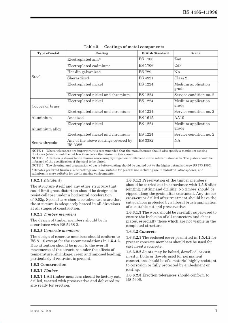
Table 2 — Coatings of metal components
1.6.2.1.2 Stability
The structure itself and any other structure that could limit gross distortion should be designed to resist collapse under a horizontal acceleration of 0.02g. Special care should be taken to ensure that the structure is adequately braced in all directions at all stages of construction.
1.6.2.2 Timber members
The design of timber members should be in accordance with BS 5268-2.
1.6.2.3 Concrete members
The design of concrete members should conform to BS 8110 except for the recommendations in 1.5.4.2. Due attention should be given to the overall movements of the structure under the effects of temperature, shrinkage, creep and imposed loading; particularly if restraint is present.
1.6.3 Construction
1.6.3.1 Timber
1.6.3.1.1 All timber members should be factory cut, drilled, treated with preservative and delivered to site ready for erection.
1.6.3.1.2 Preservation of the timber members should be carried out in accordance with 1.5.8 after jointing, cutting and drilling. No timber should be ripped along the grain after treatment. Any timber cross-cut or drilled after treatment should have the cut surfaces protected by a liberal brush application of a suitable cut-end preservative.1.6.3.1.3 The work should be carefully supervised to ensure the inclusion of all connectors and shear plates, especially those which are not visible in the completed structure.
1.6.3.2 Concrete
1.6.3.2.1 The reduced cover permitted in 1.5.4.2 for precast concrete members should not be used for cast in-situ concrete.1.6.3.2.2 Joints may be bolted, dowelled, or cast in-situ. Bolts or dowels used for permanent connections should be of a material highly resistant to corrosion or fully protected by embedment or coating.1.6.3.2.3 Erection tolerances should conform to BS 5606.
Type of metal Coating British Standard Grade
Steel
Electroplated zinca BS 1706 Zn3
Electroplated cadmiuma BS 1706 Cd3
Hot dip galvanized BS 729 NA
Sherardized BS 4921 Class 2
Electroplated nickel BS 1224 Medium application grade
Electroplated nickel and chromium BS 1224 Service condition no. 2
Copper or brassElectroplated nickel BS 1224 Medium application
grade
Electroplated nickel and chromium BS 1224 Service condition no. 2
Aluminium Anodized BS 1615 AA10
Aluminium alloyElectroplated nickel BS 1224 Medium application
grade
Electroplated nickel and chromium BS 1224 Service condition no. 2
Screw threads Any of the above coatings covered by BS 3382
BS 3382 NA
NOTE 1 Where tolerances are important it is recommended that the manufacturer should also specify a maximum coating thickness (which should be not less than twice the minimum thickness).NOTE 2 Attention is drawn to the clauses concerning hydrogen embrittlement in the relevant standards. The plater should be informed of the specification of the steel to be plated.NOTE 3 The cleaning and preparation of parts before coating should be carried out to the highest standard (see BS 773:1995).a Denotes preferred finishes. Zinc coatings are more suitable for general use including use in industrial atmospheres, and cadmium is more suitable for use in marine environments.
BS 4485-4:1996
8 © BSI 07-1999
1.7 Packings, water distribution systems, eliminators and cladding1.7.1 General
Packings should be designed and constructed to facilitate examination, maintenance, removal and dismantling.
1.7.2 Packings
1.7.2.1 Timber packing
1.7.2.1.1 Timber packing should comprise timber splash bars of rectangular or triangular or trapezoidal cross-sections, suitably supported by a timber or reinforced concrete structure. It should be firmly attached to the support structure in order to prevent displacement or damage by wind induced vibrations.1.7.2.1.2 Timber should conform to 1.5.7.1.7.2.1.3 Splash bars should be treated with copper/chromium/arsenic (CCA) preservative in accordance with 1.5.8.1.7.2.1.4 Splash bars should be designed to withstand the stresses resulting from self weight and water loading.1.7.2.1.5 Additional loading may result from ice formation in the absence of a de-icing system. If such a system is fitted, the effects of a malfunction of the system and the effects of cold water being distributed over the packing in inclement weather should be considered.1.7.2.1.6 Finger jointing should be permitted in splash bars if the layout requires excessive lengths to be installed.1.7.2.1.7 Finger jointing should conform to BS EN 385.
1.7.2.2 Asbestos-cement packing
1.7.2.2.1 Asbestos-cement packing should comprise corrugated or flat asbestos-cement sheeting installed on edge and suitably supported.1.7.2.2.2 Asbestos-cement sheets for packing should conform to BS 690 except for the following:
a) partial replacement of the asbestos fibre by an alternative fibre is permissible;b) thickness may be less than that specified in BS 690;c) variation in nominal moulded widths, giving a non-standard width of sheet, is permitted.
Non-standard sheets should be clearly marked to this effect.Since corrugated asbestos-cement sheeting used in packing will in most cases have a profile identical to sheets used for roofing or cladding, their use for these other purposes should be strictly avoided.
1.7.2.2.3 Sheeting spacing should be maintained by the use of prefabricated spacers with tie rods if necessary.1.7.2.2.4 Suitable bearing spacers should be provided between each sheet at the points of support to avoid local damage to the sheets.1.7.2.2.5 Distribution pipework or other concentrated loadings on the upper surface of the sheeting, should be adequately spread to avoid local damage to the sheets.
1.7.2.3 Plastics packing
1.7.2.3.1 Plastics packing comprises either:a) splash packing consisting of laths or grids of cross splash bars, and installed in layers; orb) film packing, fabricated in modules generally of a proprietary design and installed one above the other to the requisite depth.
1.7.2.3.2 Plastics materials should conform to 1.5.10.1.7.2.3.3 The module type of construction used for the film packing, capable of withstanding the stresses resulting from self weight and water loading, should also take into account excess loads resulting from deposits on the packing which may result in high local crushing stress at points of support.1.7.2.3.4 If a plastics splash packing is installed, the effects of ice build-up, described in 1.7.2.1.5, should be taken into account.
1.7.3 Water distribution pipework
17.3 Pipework should be in accordance with 1.5.14.1.7.3.2 Pipework should have a wall thickness that allows the fixing of spray nozzles or adaptors.1.7.3.3 Pipework and its supporting system should be able to accommodate all thermal stresses and movements due to changes in water and ambient temperatures.1.7.3.4 Pipework should be fitted with sluicing valves so that pipes may be regularly flushed to remove debris, silt, etc. Such sluicing valves should be fitted regardless of whether the nozzles spray upwards or downwards.1.7.3.5 The pipework should be capable of resisting surge pressures appropriate to the system and of at least twice the working pressure.1.7.3.6 Joints in pipework should be formed using methods and components appropriate for the type of pipework adopted and should be capable of resisting the same loadings as the parent pipe.1.7.3.7 Adhesives used in joint formation should be in accordance with 1.5.13.
BS 4485-4:1996
© BSI 07-1999 9
1.7.4 Drift eliminatorsNOTE The form and function of drift eliminators is described in 8.2 of BS 4485-3:1987.
1.7.4.1 Asbestos-cement eliminators should be formed from asbestos-cement sheeting conforming to BS 690.1.7.4.2 Proprietary eliminators should be fabricated from a thermoplastic material of a type described in Annex B.1.7.4.3 Unless the eliminator is pre-formed in panels or modules of adequate dead weight, individual louvres should be secured by wedging in or nailing to the support member.
1.7.5 Cladding
1.7.5.1 Fixings and seals should be used to prevent leakage between joints or fixings.1.7.5.2 Fixings should withstand the designed wind induced positive and negative pressures and any vibrations within the tower.1.7.5.3 Surface treatment of the sheets should be considered depending on the nature of the water in the tower, it should be carried out in accordance with manufacturer’s instructions.
1.8 Cooling tower fittings1.8.1 General
Cooling tower fittings should be designed to withstand the often corrosive service conditions within the cooling tower and should conform to appropriate British Standards. Fittings specific to cooling towers should be in accordance with 1.8.2 to 1.8.6.
1.8.2 Damboards
Damboards may be used to isolate the cold water basin of larger towers. They should be designed to fit into guides set into the flow channel to provide a seal for water pressure from either side.Boards should seal to the guides, and joints between boards should be rebated or tongued and grooved to minimize leakage. Butyl or similar rubber seals may be used.Storage conditions should ensure minimal warping, and timber boards should be stored under water.Timber boards should be designed in accordance with BS 5268-2, treated in accordance with 1.5.8 and shod with cast iron or other suitable material to prevent damage during lifting.
1.8.3 Coarse screens
Coarse screens should be designed to resist water pressures occurring with at least 25 % of the screen-free area blocked. Provision should be made for their removal for cleaning.
1.8.4 Aircraft warning lights
It is essential that the Civil Aviation Authority is consulted for specific guidance/advice on the need for and extent of aircraft warning lights.Depending on the distance of the tower from the airfield, warning lights may need to be installed, in accordance with planning regulations, on towers above 92 m in height. Towers above 153 m in height should be lit.Lamps should be fitted not closer than 6 m to the top. The lamps and associated cables should be suitably protected.Lamps should be visible from every angle in azimuth 16 miles from the tower. The actual position and numbers of lamps or clusters should depend on the spread and intensity of the light, the estimated life of the lamp and the level of expected maintenance.If steeplejack sockets are provided for access they should be in accordance with BS 3572.
1.8.5 Lightning protection
Lightning protection, if used, should be in accordance with BS 6651.External protective systems are not normally required for concrete cooling tower shells. Sufficient protection is afforded by the existing reinforcement provided that good contact is maintained between bars through fixing with tying wire as follows:
a) between lapped vertical bars;b) between vertical and horizontal bars;c) between the reinforcement in the shell and the supporting ringbeam and column bars.
An earth check should be carried out to see if additional lightning protection is required.
1.8.6 Barriers, ladders and walkways
Where there is vehicular access to a barrier it should conform to the relevant requirements of BS 6180.Ladders should be in accordance with type A of BS 4211.Metal walkways should be in accordance with BS 5395-3.Wooden walkways should be in accordance with 1.5.7, 1.5.8, 1.6.1 and 1.6.2.1.
1.9 Water retaining structures1.9.1 General
The distribution system, the cold water basin and sump or suction line should be designed, constructed and tested generally in accordance with BS 8007.NOTE This clause applies to such structures made from reinforced or prestressed concrete.
BS 4485-4:1996
10 © BSI 07-1999
1.9.2 Loads
1.9.2.1 Internal water load
The normal load should be taken as that corresponding to water at the normal operating level and pressure.The maximum water load in closed sections of the distribution system should be accounted for. It will arise as a result of possible pressure surges from normal pump operation and possible blockages in the system as well as the pressures anticipated in the normal operation of the tower. Abnormal pressures may be alleviated by the incorporation of open topped stand pipe(s) or an open surge chamber of sufficient size to accommodate the maximum possible flow; the maximum pressure in such a system should be at least equivalent to a head of water 0.5 m above the top of the stand pipe(s) or surge chamber.The maximum load in open flumes should be taken as equivalent to the pressure of water at the top of wall level and, in the cold water basin, equivalent to the pressure of water at basin kerb level.
1.9.2.2 External water load
The cold water basin may be below ground level. In this case the ground water may be at a higher level than the basin slab. In this event, the effect of external water pressure on the basin walls and bottom slab should be taken into account.
1.9.2.3 Other loads
If the water retaining structures support other sections of the tower the loads applied should be taken into account.Loads arising from temporary construction conditions, construction plant and temperature gradients should also be considered.
1.9.3 Design
If the maximum water load is not more than 10 % greater than the normal load, the structures should be designed for the normal load.If the maximum water load is more than 10 % greater than the normal load, the structures should be designed for 90 % of the maximum load.
Internal and external water pressures should be considered as acting in isolation.If the pressures from external water cannot be practicably resisted, pressure relief “blow out” panels may be incorporated in the basin. They should be of such design, size and spacing that they will prevent damage to the structure from unbalanced external water pressure.Construction and other joints should have waterstops and sealers in accordance with BS 8007.Connections to pipes should incorporate puddle flanges or other similar sealing devices.
1.9.4 Testing
The structures should be tested for watertightness in accordance with section 9 of BS 8007:1987.
1.10 Foundations and bases1.10.1 Foundations
The foundations should be designed in accordance with BS 8004.Differential settlements within the foundations that support cooling tower shells (type 1 towers) should be minimized. If differential settlement is anticipated, its magnitude and location should be evaluated for allowance in the design.Attention should be paid to the potential differential movements between the shell support, pond and packing support foundations owing to their different intensities of loading and/or different foundation types (e.g. piled and contact).In derivation of foundation design parameters the potentially saturated ground conditions around and under cooling towers should be taken into account.
1.10.2 Bases
The reinforced concrete bases should be designed in accordance with BS 8110 to transmit to the foundations all the forces in the shell support structure, plus any loadings arising from the cold water basin.The possible effect of loading resulting from temporary works or maintenance should also be considered.
BS 4485-4:1996
© BSI 07-1999 11
Section 2. Hyperboloidal cooling towers (type 1 towers)2.1 Basis of designNOTE The basis of design applies to shells of hyperboloidal and offset hyperboloidal form.
2.1.1 The design of the reinforced concrete shell and its supports should be in accordance with BS 8110 except where amended by specific recommendations of this standard.2.1.2 In the design of the shell structure a shell theory based on bending analysis should be used.2.1.3 Aero-elastic model testing in an atmospheric boundary layer wind tunnel should be undertaken to determine the stresses in the shell if the tower being designed is greater than 120 m in total height and one or more of the following conditions apply:
a) the tower forms part of a tower group (i.e. of two or more towers);b) the tower is close to large buildings;c) the tower is liable to be affected by topographical features;d) the tower has unusual proportions or any novel structural design features.
Such testing should be used to confirm the applicability of the design methods given in this standard. Appropriate methods of testing are considered in Annex C.
2.2 Loading2.2.1 Dead loads
Dead loads should be calculated from the actual weights of the materials used.
2.2.2 Wind loads
2.2.2.1 General
The derivation of wind loads in BS 6399-2 applies except for.
a) the derivation of design gust speed, Vg,z (see 2.2.2.3);b) the effects of nearby structures on the mean and fluctuating pressures on the tower shell (see 2.2.2.6).
Two design wind speeds are used to derive the wind loads on the tower: the design mean wind speed, Vm,z, which is the hourly mean wind speed (in m/s), and the design gust speed, Vg,z, which is not a profile of the physical wind speeds of a predetermined duration but is specified to produce appropriate design stresses on the windward meridian of an isolated cooling tower. Both design wind speeds relate to wind speeds which vary with height z(in m) above ground level; the probability of exceeding their predetermined values is 0.02 in any one year.
Wind speeds should be derived in accordance with BS 6399-2 and 2.2.2.2 and 2.2.2.3. A value of 1.00 for Sd should normally be used.The value of Sh used should not be less than 0. Upwind of the topographic crest the average Sh should not be greater than 0.12 over the height of the tower at its centre-line. Downwind of the topographic crest the average Sh should not be greater than 0.12 over the height of the tower on the windward meridian. Otherwise specialist advice should be sought.
2.2.2.2 Design mean wind speed
The design mean wind speed is given byVm,z = VsSm,z
whereSm,z = Sc (1 + Sh) for country terrain; and
Sm,z = ScTc (1 + Sh) for town terrain.
Sc, Tc and Sh are as given in BS 6399-2 and vary with effective height (He).
2.2.2.3 Design gust speed
The design gust speed is given byVg,z = VsSg,z
where
Sc, Tc, Sh are as given in BS 6399 and vary with effective height (He);
St,H and Tt,H are constants equal to the value of St and Tt evaluated at the height of the tower, H, above ground level.
2.2.2.4 Dynamic wind pressure
The following relationship should be assumed for the dynamic wind pressure q (in N/m2) at height z metres.
qz = kVz2
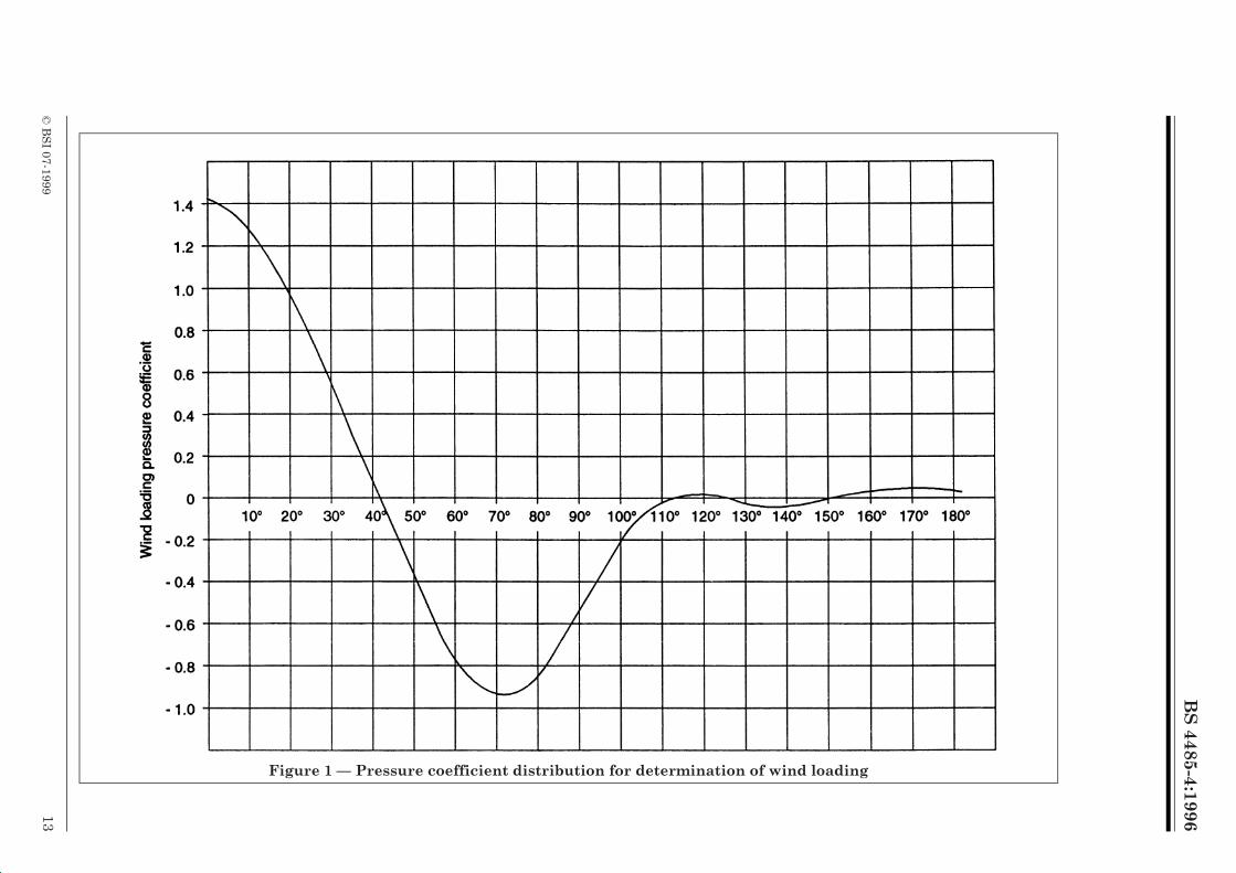
2.2.2.5 Pressure distribution
The pressure coefficient distribution used to determine the wind loading on shells should be of the form given in Figure 1.
wherek = 0.613Vz is the relevant wind speed Vm,z or
Vg,z (in m/s) as defined in 2.2.2.2 and 2.2.2.3.
BS 4485-4:1996
12 © BSI 07-1999
This distribution includes an allowance for internal suction and should be used over the complete tower height with the dynamic wind pressure, qz.For calculation purposes this curve may be defined by the following expression:
NOTE For further information on the derivation of this distribution refer to Annex D.
2.2.2.6 Adjacent structures
The effect of nearby structures on the mean and fluctuating pressures over the shell surface can be severe (particularly for adjacent towers of similar size). It is not possible to specify design pressure distributions to allow for these effects so correction factors are given in 2.3.5.3 for meridional stress resultants calculated in an isolated cooling tower shell.
2.2.3 Imposed loads
Loading of the shell by permanent fixings should be minimized. The local effects of attachments on the structure should be investigated.
2.2.4 Foundation settlement loads
If the design of the foundation is such that differential settlements will occur within the shell support structure, these should be taken into account in the design of the tower shell and should be treated as an additional loading case.
2.2.5 Constructional loads
Loads arising during construction should be taken into consideration in the design.NOTE Constructional loads may include the following:
a) transportation of concrete;b) scaffolding and formwork;c) correcting shutter alignment;d) hoist fixings;e) storage of materials on scaffold;f) temporary access;g) tower crane fixings.
2.2.6 Thermal loads
Thermal loads on towers caused by solar and operational variations do not significantly affect the ultimate limit state unless there are rapid changes of section in the shell or the supports are very stiff in the direction normal to the shell. Normal serviceability requirements are met by the minimum reinforcement provided in the shell (see 2.3.5.5.1).
2.3 Design considerations2.3.1 Ultimate limit state design
Partial safety factors should be applied to the loads specified in 2.2 as follows:
a) for design of the tower shell: — load combination i) 1.0Gk + 1.5ÎGWk
— Load combination ii) 1.4Gk + 1.5ÎGWk
b) for design of the shell support structure: — load combination iii) 1.0Gk + 1.5ÎFWk
— load combination iv) 1.4Gk + 1.5ÎFWk
NOTE The partial factor of 1.5 applied to wind load has been increased from the 1.4 value used in BS 8110 in view of the sensitivity of the structure to wind loading.
Partial safety factors in accordance with 2.4.2 of BS 8110-1:1985 should be applied to the characteristic strength of the materials.
2.3.2 Buckling design
2.3.2.1 General
Buckling design should be undertaken in accordance with BS 8110 for the tower under characteristic loads, as appropriate.
2.3.2.2 Local buckling of the shell
The factor of safety against buckling should be checked by the following procedure under the loading combination of (1.0Gk + 1.0ÎIWk), where ÎI is an amplification factor defined in 2.3.5.2.
wherea0 = – 0.00071 a4 = 0.10756
a1 = 0.24611 a5 = – 0.09579
a2 = 0.62296 a6 = – 0.01142
a3 = 0.48833 a7 = 0.04551
Ú is the angular position measured from the incident wind direction, in degrees.
whereGk is the characteristic dead load;
Wk is the hourly mean wind load;
ÎG and ÎF are amplification factors defined in 2.3.5.2.
BS
4485-4:1996
© B
SI 07-1999
13
Figure 1 — Pressure coefficient distribution for determination of wind loading
BS 4485-4:1996
14 © BSI 07-1999
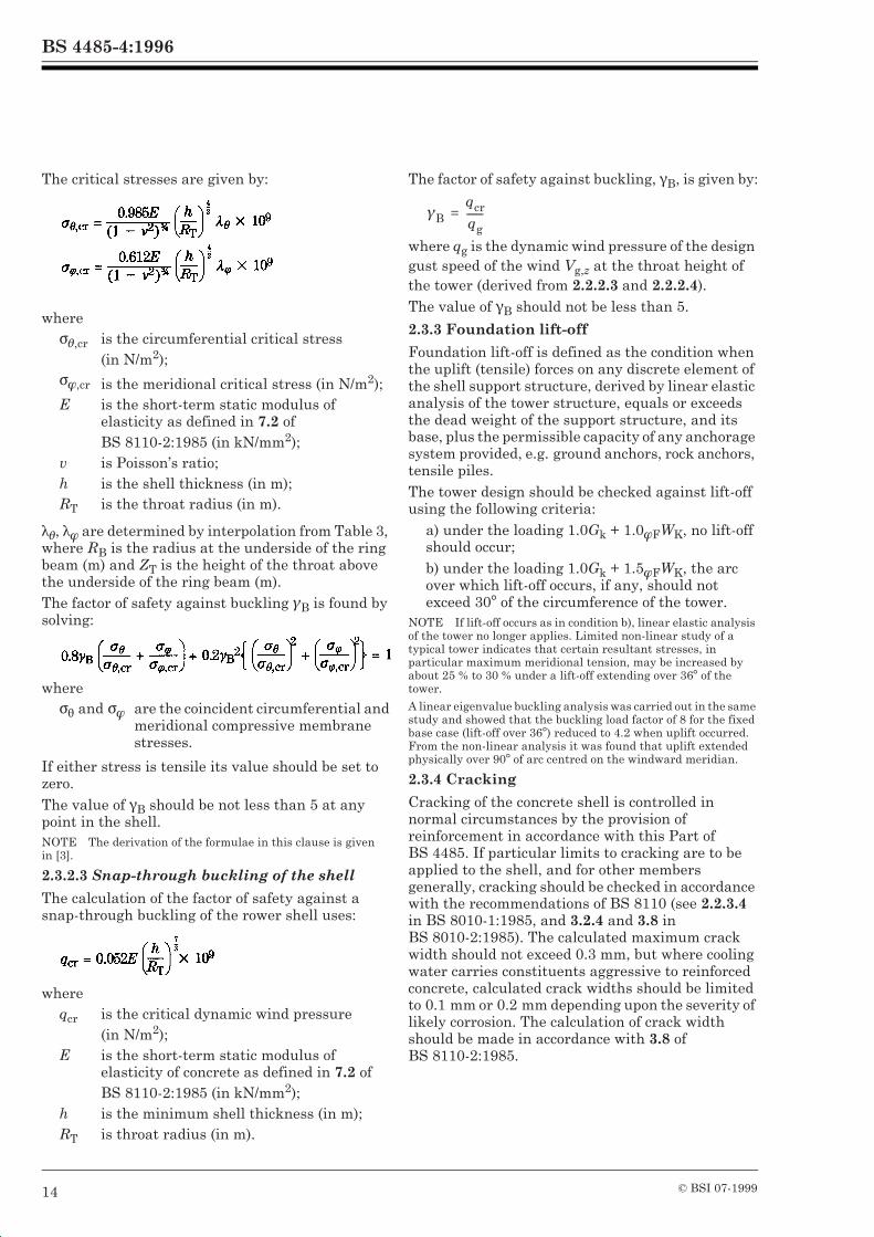
The critical stresses are given by:
2Ú, 2Î are determined by interpolation from Table 3, where RB is the radius at the underside of the ring beam (m) and ZT is the height of the throat above the underside of the ring beam (m).The factor of safety against buckling ¾B is found by solving:
If either stress is tensile its value should be set to zero.The value of *B should be not less than 5 at any point in the shell.NOTE The derivation of the formulae in this clause is given in [3].
2.3.2.3 Snap-through buckling of the shell
The calculation of the factor of safety against a snap-through buckling of the rower shell uses:
The factor of safety against buckling, *B, is given by:
where qg is the dynamic wind pressure of the design gust speed of the wind Vg,z at the throat height of the tower (derived from 2.2.2.3 and 2.2.2.4).The value of *B should not be less than 5.
2.3.3 Foundation lift-off
Foundation lift-off is defined as the condition when the uplift (tensile) forces on any discrete element of the shell support structure, derived by linear elastic analysis of the tower structure, equals or exceeds the dead weight of the support structure, and its base, plus the permissible capacity of any anchorage system provided, e.g. ground anchors, rock anchors, tensile piles. The tower design should be checked against lift-off using the following criteria:
a) under the loading 1.0Gk + 1.0ÎFWK, no lift-off should occur;b) under the loading 1.0Gk + 1.5ÎFWK, the arc over which lift-off occurs, if any, should not exceed 30° of the circumference of the tower.
NOTE If lift-off occurs as in condition b), linear elastic analysis of the tower no longer applies. Limited non-linear study of a typical tower indicates that certain resultant stresses, in particular maximum meridional tension, may be increased by about 25 % to 30 % under a lift-off extending over 36° of the tower.
A linear eigenvalue buckling analysis was carried out in the same study and showed that the buckling load factor of 8 for the fixed base case (lift-off over 36°) reduced to 4.2 when uplift occurred. From the non-linear analysis it was found that uplift extended physically over 90° of arc centred on the windward meridian.
2.3.4 Cracking
Cracking of the concrete shell is controlled in normal circumstances by the provision of reinforcement in accordance with this Part of BS 4485. If particular limits to cracking are to be applied to the shell, and for other members generally, cracking should be checked in accordance with the recommendations of BS 8110 (see 2.2.3.4 in BS 8010-1:1985, and 3.2.4 and 3.8 in BS 8010-2:1985). The calculated maximum crack width should not exceed 0.3 mm, but where cooling water carries constituents aggressive to reinforced concrete, calculated crack widths should be limited to 0.1 mm or 0.2 mm depending upon the severity of likely corrosion. The calculation of crack width should be made in accordance with 3.8 of BS 8110-2:1985.
whereBÚ,cr is the circumferential critical stress
(in N/m2);BÎ,cr is the meridional critical stress (in N/m2);E is the short-term static modulus of
elasticity as defined in 7.2 of BS 8110-2:1985 (in kN/mm2);
v is Poisson’s ratio;h is the shell thickness (in m);RT is the throat radius (in m).
whereBF and BÎ are the coincident circumferential and
meridional compressive membrane stresses.
whereqcr is the critical dynamic wind pressure
(in N/m2);E is the short-term static modulus of
elasticity of concrete as defined in 7.2 of BS 8110-2:1985 (in kN/mm2);
h is the minimum shell thickness (in m);RT is throat radius (in m).
¾Bqcrqg--------=
BS 4485-4:1996
© BSI 07-1999 15
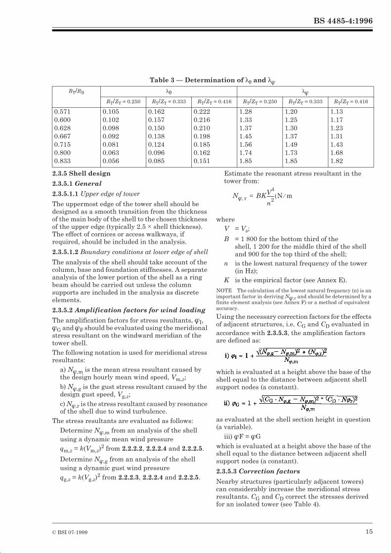
Table 3 — Determination of 2F and 2Î
2.3.5 Shell design
2.3.5.1 General
2.3.5.1.1 Upper edge of tower
The uppermost edge of the tower shell should be designed as a smooth transition from the thickness of the main body of the shell to the chosen thickness of the upper edge (typically 2.5 × shell thickness). The effect of cornices or access walkways, if required, should be included in the analysis.
2.3.5.1.2 Boundary conditions at lower edge of shell
The analysis of the shell should take account of the column, base and foundation stiffnesses. A separate analysis of the lower portion of the shell as a ring beam should be carried out unless the column supports are included in the analysis as discrete elements.
2.3.5.2 Amplification factors for wind loading
The amplification factors for stress resultants, ÎI, ÎG and ÎF should be evaluated using the meridional stress resultant on the windward meridian of the tower shell.The following notation is used for meridional stress resultants:
a) NÎ,m is the mean stress resultant caused by the design hourly mean wind speed, Vm,z;b) NÎ,g is the gust stress resultant caused by the design gust speed, Vg,z;c) NÎ,r is the stress resultant caused by resonance of the shell due to wind turbulence.
The stress resultants are evaluated as follows:Determine NÎ,m from an analysis of the shell using a dynamic mean wind pressureqm,z = k(Vm,z)
2 from 2.2.2.2, 2.2.2.4 and 2.2.2.5.
Determine NÎ,g from an analysis of the shell using a dynamic gust wind pressureqg,z = k(Vg,z)
2 from 2.2.2.3, 2.2.2.4 and 2.2.2.5.
Estimate the resonant stress resultant in the tower from:
NOTE The calculation of the lowest natural frequency (n) is an important factor in deriving NÎ,r and should be determined by a finite element analysis (see Annex F) or a method of equivalent accuracy.
Using the necessary correction factors for the effects of adjacent structures, i.e. CG and CD evaluated in accordance with 2.3.5.3, the amplification factors are defined as:
which is evaluated at a height above the base of the shell equal to the distance between adjacent shell support nodes (a constant).
as evaluated at the shell section height in question (a variable).
iii) ÎF = ÎGwhich is evaluated at a height above the base of the shell equal to the distance between adjacent shell support nodes (a constant).
2.3.5.3 Correction factors
Nearby structures (particularly adjacent towers) can considerably increase the meridional stress resultants. CG and CD correct the stresses derived for an isolated tower (see Table 4).
RT/RB 2F 2Î
RT/ZT = 0.250 RT/ZT = 0.333 RT/ZT = 0.416 RT/ZT = 0.250 RT/ZT = 0.333 RT/ZT = 0.416
0.5710.6000.6280.6670.7150.8000.833
0.1050.1020.0980.0920.0810.0630.056
0.1620.1570.1500.1380.1240.0960.085
0.2220.2160.2100.1980.1850.1620.151
1.281.331.371.451.561.741.85
1.201.251.301.371.491.731.85
1.131.171.231.311.431.681.82
whereV = Vs;
B = 1 800 for the bottom third of the shell, 1 200 for the middle third of the shell and 900 for the top third of the shell;
n is the lowest natural frequency of the tower (in Hz);
K is the empirical factor (see Annex E).
NÎ r, BKV4
n2------- N m⁄( )=
BS 4485-4:1996
16 © BSI 07-1999
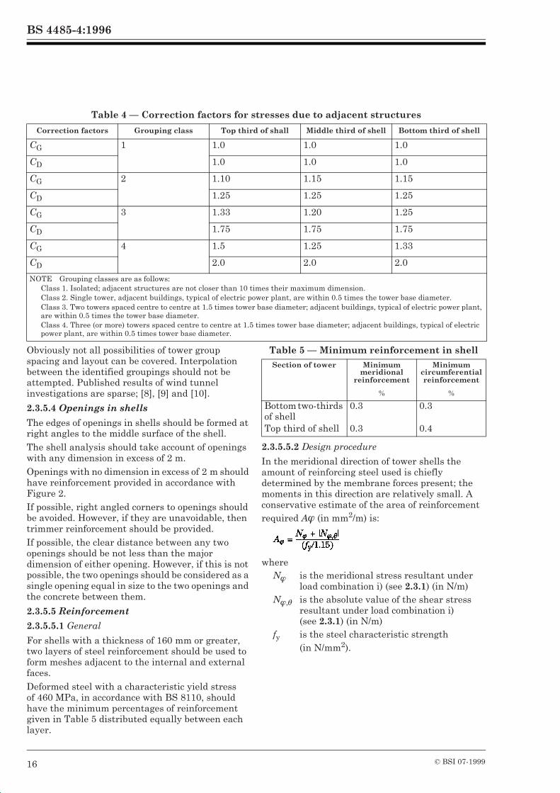
Table 4 — Correction factors for stresses due to adjacent structures
Obviously not all possibilities of tower group spacing and layout can be covered. Interpolation between the identified groupings should not be attempted. Published results of wind tunnel investigations are sparse; [8], [9] and [10].
2.3.5.4 Openings in shells
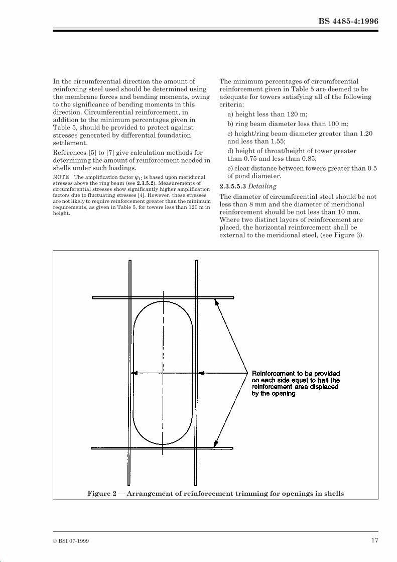
The edges of openings in shells should be formed at right angles to the middle surface of the shell.The shell analysis should take account of openings with any dimension in excess of 2 m.Openings with no dimension in excess of 2 m should have reinforcement provided in accordance with Figure 2.If possible, right angled corners to openings should be avoided. However, if they are unavoidable, then trimmer reinforcement should be provided.If possible, the clear distance between any two openings should be not less than the major dimension of either opening. However, if this is not possible, the two openings should be considered as a single opening equal in size to the two openings and the concrete between them.
2.3.5.5 Reinforcement
2.3.5.5.1 General
For shells with a thickness of 160 mm or greater, two layers of steel reinforcement should be used to form meshes adjacent to the internal and external faces.Deformed steel with a characteristic yield stress of 460 MPa, in accordance with BS 8110, should have the minimum percentages of reinforcement given in Table 5 distributed equally between each layer.
Table 5 — Minimum reinforcement in shell
2.3.5.5.2 Design procedure
In the meridional direction of tower shells the amount of reinforcing steel used is chiefly determined by the membrane forces present; the moments in this direction are relatively small. A conservative estimate of the area of reinforcement required AÎ (in mm2/m) is:
Correction factors Grouping class Top third of shall Middle third of shell Bottom third of shell
CG 1 1.0 1.0 1.0
CD 1.0 1.0 1.0
CG 2 1.10 1.15 1.15
CD 1.25 1.25 1.25
CG 3 1.33 1.20 1.25
CD 1.75 1.75 1.75
CG 4 1.5 1.25 1.33
CD 2.0 2.0 2.0
NOTE Grouping classes are as follows: Class 1. Isolated; adjacent structures are not closer than 10 times their maximum dimension.Class 2. Single tower, adjacent buildings, typical of electric power plant, are within 0.5 times the tower base diameter.Class 3. Two towers spaced centre to centre at 1.5 times tower base diameter; adjacent buildings, typical of electric power plant, are within 0.5 times the tower base diameter.Class 4. Three (or more) towers spaced centre to centre at 1.5 times tower base diameter; adjacent buildings, typical of electric power plant, are within 0.5 times tower base diameter.
Section of tower Minimum meridional
reinforcement
Minimum circumferential reinforcement
% %
Bottom two-thirds of shellTop third of shell
0.3
0.3
0.3
0.4
whereNÎ is the meridional stress resultant under
load combination i) (see 2.3.1) (in N/m)NÎ,Ú is the absolute value of the shear stress
resultant under load combination i)(see 2.3.1) (in N/m)
fy is the steel characteristic strength (in N/mm2).
BS 4485-4:1996
© BSI 07-1999 17
In the circumferential direction the amount of reinforcing steel used should be determined using the membrane forces and bending moments, owing to the significance of bending moments in this direction. Circumferential reinforcement, in addition to the minimum percentages given in Table 5, should be provided to protect against stresses generated by differential foundation settlement.References [5] to [7] give calculation methods for determining the amount of reinforcement needed in shells under such loadings.NOTE The amplification factor ÎG is based upon meridional stresses above the ring beam (see 2.3.5.2). Measurements of circumferential stresses show significantly higher amplification factors due to fluctuating stresses [4]. However, these stresses are not likely to require reinforcement greater than the minimum requirements, as given in Table 5, for towers less than 120 m in height.
The minimum percentages of circumferential reinforcement given in Table 5 are deemed to be adequate for towers satisfying all of the following criteria:
a) height less than 120 m;b) ring beam diameter less than 100 m;c) height/ring beam diameter greater than 1.20 and less than 1.55;d) height of throat/height of tower greater than 0.75 and less than 0.85;e) clear distance between towers greater than 0.5 of pond diameter.
2.3.5.5.3 Detailing
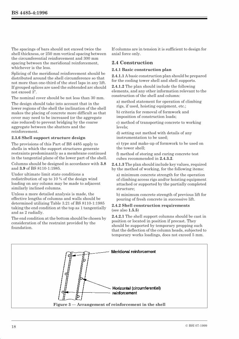
The diameter of circumferential steel should be not less than 8 mm and the diameter of meridional reinforcement should be not less than 10 mm. Where two distinct layers of reinforcement are placed, the horizontal reinforcement shall be external to the meridional steel, (see Figure 3).
Figure 2 — Arrangement of reinforcement trimming for openings in shells
BS 4485-4:1996
18 © BSI 07-1999
The spacings of bars should not exceed twice the shell thickness, or 250 mm vertical spacing between the circumferential reinforcement and 300 mm spacing between the meridional reinforcement, whichever is the less.Splicing of the meridional reinforcement should be distributed around the shell circumference so that not more than one-third of the steel laps in any lift. If grouped splices are used the subtended arc should not exceed 3°.The nominal cover should be not less than 30 mm.The design should take into account that in the lower regions of the shell the inclination of the shell makes the placing of concrete more difficult so that cover may need to be increased (or the aggregate size reduced) to prevent bridging by the coarse aggregate between the shutters and the reinforcement.
2.3.6 Shell support structure design
The provisions of this Part of BS 4485 apply to shells in which the support structures generate restraints predominantly as a membrane continued in the tangential plane of the lower part of the shell.Columns should be designed in accordance with 3.8 and 3.9 of BS 8110-1:1985.Under ultimate limit state conditions a redistribution of up to 10 % of the design wind loading on any column may be made to adjacent similarly inclined columns.Unless a more detailed analysis is made, the effective lengths of columns and walls should be determined utilizing Table 3.21 of BS 8110-1:1985 taking the end condition at the top as 1 tangentially and as 2 radially.The end condition at the bottom should be chosen by consideration of the restraint provided by the foundation.
If columns are in tension it is sufficient to design for axial force only.
2.4 Construction2.4.1 Basic construction plan
2.4.1.1 A basic construction plan should be prepared for the cooling tower shell and shell supports.2.4.1.2 The plan should include the following elements, and any other information relevant to the construction of the shell and column:
a) method statement for operation of climbing rigs, if used, hoisting equipment, etc.;b) criteria for removal of formwork and imposition of construction loads;c) method of transporting concrete to working levels;d) setting out method with details of any instrumentation to be used;e) type and make-up of formwork to be used on the tower shell;f) method of storing and curing concrete test cubes recommended in 2.4.3.2.
2.4.1.3 The plan should include key values, required by the method of working, for the following items:
a) minimum concrete strength for the operation of climbing access rigs and/or hoisting equipment attached or supported by the partially completed structure;b) minimum concrete strength of previous lift for pouring of fresh concrete in successive lift.
2.4.2 Shell construction requirements (see also 1.5.5)
2.4.2.1 The shell support columns should be cast in position or located in position if precast. They should be supported by temporary propping such that the deflection of the column heads, subjected to temporary works loadings, does not exceed 5 mm.
Figure 3 — Arrangement of reinforcement in the shell
BS 4485-4:1996
© BSI 07-1999 19
2.4.2.2 No props should be removed until a complete lift of the ring beam, not less than 1 m deep, has been cast and has attained a compressive strength, as determined by match cured test cubes, of not less than 20 N/mm2.2.4.2.3 No climbing rigs, hoisting equipment, etc. should be attached to the shell within a 36° arc from a stop end until the first lift of the ring beam is completed.
2.4.3 Quality control of shell concrete
2.4.3.1 The striking of formwork should only be carried out when the concrete has reached an appropriate maturity level.2.4.3.2 The operations of pouring fresh concrete and of moving climbing rigs and/or hoisting equipment should be governed by the results of match cured compressive test cubes.NOTE A match cured test cube is defined as a cube that is manufactured, stored, cured and tested in such a way that it realistically reflects the behaviour of the parent concrete.
2.4.3.3 At least four test cubes should be made from samples taken at the point of discharge into the formwork at locations diametrically opposite to each other in any lift pour.
2.4.3.4 These cubes should be taken at least once every two lifts or every 3 m of shell height, whichever is the lesser.2.4.3.5 Two test cubes should be match cured for a period of time considered to be representative of the pouring cycle.2.4.3.6 One of the match cured cubes should be crushed; if its compressive strength falls below the key value given in the basic construction plan for the operation of pouring fresh concrete, then after an appropriate period of time the second cube should be crushed. No further concrete should be poured until the concrete in the corresponding lift has achieved sufficient strength to withstand any loads which are to be imposed upon it.2.4.3.7 The two remaining test cubes should be match cured for a period of time representative of the rig moving cycle and should then be tested.2.4.3.8 If the compressive strength of either cube falls below the key value given in the basic construction plan for the operation of moving climbing rigs and/or hoisting equipment, no lifting operation should be carried out until the concrete in the lift which is required to withstand the loadings from rig and/or hoisting equipment has achieved sufficient strength to do so.
BS 4485-4:1996
20 © BSI 07-1999
Section 3. Mechanical draught towers (type 2 towers)3.1 Characteristic loads3.1.1 Dead loads
Dead loads should be calculated from the actual weights of the materials used.
3.1.2 Imposed loads
The characteristic imposed loads should be calculated in accordance with BS 6399-1.The effects of dynamic loading from machinery or fans on the structure should be considered. This should take account of the possibility of breakage of a fan blade.
3.1.3 Wind loads
The design wind speed applicable to the design of mechanical draught cooling towers should be determined from BS 6399-2.In assessing the overall stability of the installation, the effect of wind loading on a dry and out of commission tower should be considered.
3.1.4 Temperature effects
Allowance should be made in the design both for overall thermal expansion of the structure and for temperature gradients across sections.Temperature gradients should be derived from the maximum air or water temperature within the tower and the corresponding minimum ambient temperature.
3.2 Design considerations3.2.1 Design standards
Sections of reinforced concrete structures which retain water should be designed in accordance with BS 8007. Other reinforced concrete should be designed in accordance with BS 8110.
Steel structures should be designed in accordance with BS 5950.Timber structures should be designed in accordance with BS 5268-2.
3.2.2 Resonance
The natural frequencies of members supporting machinery or fans should be calculated under normal working conditions. No such calculated natural frequency should lie within ± 20 % of the frequency of any dynamic loading applied by the machinery or fan when operating at normal working speed.NOTE To ensure compliance with this criterion it may be necessary to consider more than just the first mode of vibration of the fan support structure.
The supporting structure for the fan equipment should be in accordance with the fan manufacturer’s requirements. However, it is recommended that the fan supporting structure should be arranged so that the fan blades are not subjected to simultaneous buffeting along their entire length, and that no supporting beam should be positioned directly along the radius of a fan blade.The tower structure and the beam support for the fan equipment should be designed to minimize blockage of the air flow into the fan and to ensure that the consequential aerodynamic buffeting is not significant under any normal operating condition.
BS 4485-4:1996
© BSI 07-1999 21
Annex A (normative) Recommendations for stress graded timber triangular section laths
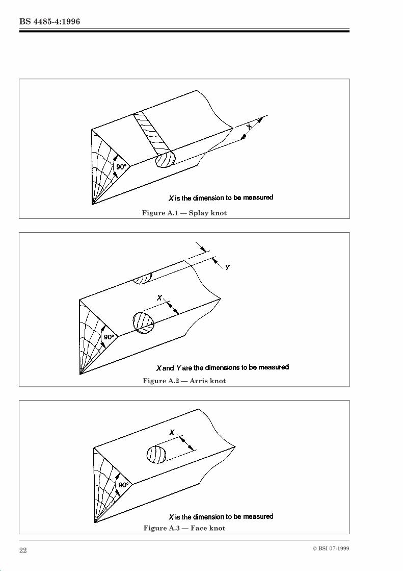
A.1 GeneralAll section laths should be manufactured from Pinus sylvestris or other approved timber species.In no case should the finished sawn size be less than the design dimensions.After conversion to size, the laths should be stress graded in accordance with the rules given below.Each lath should be graded by assessing the characteristics covered by A.2 to A.7 inclusive.A.2 Rate of growthA.2.1 Measurement The rate of growth should be measured on one end of the lath and should be taken as the average number of growth rings per 25 mm intersected by the longest possible line normal to the growth rings and passing through the centre of the lath.A.2.2 Grading limitsThere should be not less than six growth rings per 25 mm.A.3 Checks, shakes and splitsA lath should not contain checks, shakes and splits.A.4 WaneA lath should not have wane.A.5 PithA lath should not contain pith in the tension zone.A.6 Slope of grainA.6.1 MeasurementThe slope of grain should be measured over a distance sufficiently great to determine the general slope, disregarding local deviations caused by knots.A.6.2 Grading limitsA lath should not have a slope of grain steeper than 1 in 6.A.7 KnotsA.7.1 SizeThe maximum permissible size of knots should be in accordance with Table A.1.A.7.2 MeasurementA.7.2.1 Splay knotsA splay knot (see 1.3.27) should be measured on the face where the end grain of the knot can be seen. Its size should be taken as the width between the arris of the section and a line touching the knot parallel with the arris (see Figure A.1).
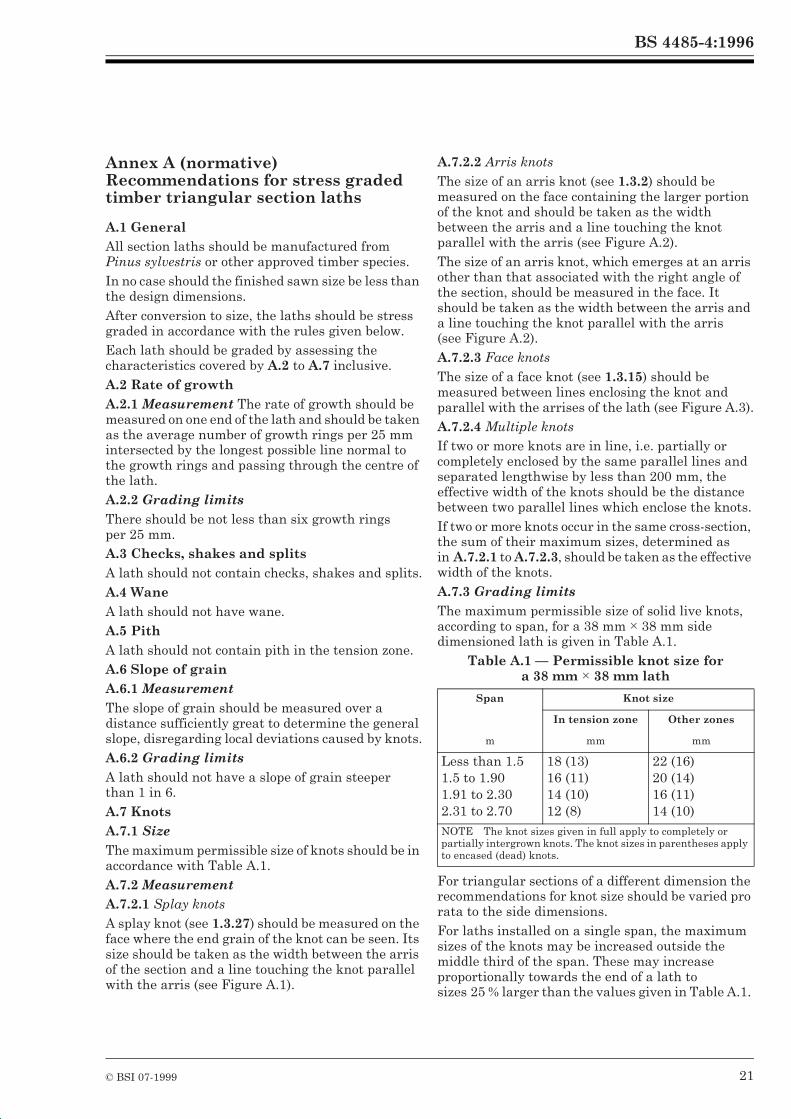
A.7.2.2 Arris knotsThe size of an arris knot (see 1.3.2) should be measured on the face containing the larger portion of the knot and should be taken as the width between the arris and a line touching the knot parallel with the arris (see Figure A.2).The size of an arris knot, which emerges at an arris other than that associated with the right angle of the section, should be measured in the face. It should be taken as the width between the arris and a line touching the knot parallel with the arris (see Figure A.2).A.7.2.3 Face knotsThe size of a face knot (see 1.3.15) should be measured between lines enclosing the knot and parallel with the arrises of the lath (see Figure A.3).A.7.2.4 Multiple knotsIf two or more knots are in line, i.e. partially or completely enclosed by the same parallel lines and separated lengthwise by less than 200 mm, the effective width of the knots should be the distance between two parallel lines which enclose the knots.If two or more knots occur in the same cross-section, the sum of their maximum sizes, determined as in A.7.2.1 to A.7.2.3, should be taken as the effective width of the knots.A.7.3 Grading limitsThe maximum permissible size of solid live knots, according to span, for a 38 mm × 38 mm side dimensioned lath is given in Table A.1.
Table A.1 — Permissible knot size for a 38 mm × 38 mm lath
For triangular sections of a different dimension the recommendations for knot size should be varied pro rata to the side dimensions.For laths installed on a single span, the maximum sizes of the knots may be increased outside the middle third of the span. These may increase proportionally towards the end of a lath tosizes 25 % larger than the values given in Table A.1.
Span Knot size
In tension zone Other zones
m mm mm
Less than 1.51.5 to 1.901.91 to 2.302.31 to 2.70
18 (13)16 (11)14 (10)12 (8)
22 (16)20 (14)16 (11)14 (10)
NOTE The knot sizes given in full apply to completely or partially intergrown knots. The knot sizes in parentheses apply to encased (dead) knots.
BS 4485-4:1996
22 © BSI 07-1999
Figure A.1 — Splay knot
Figure A.2 — Arris knot
Figure A.3 — Face knot
BS 4485-4:1996
© BSI 07-1999 23
Annex B (normative)Guidance on the use of plastics materials
B.1 Thermosetting materialsThermosetting plastics used in cooling towers are generally of an epoxy or polyester type consisting of a resin and hardener. They usually take the form of glass fibre reinforced plastics components. Once set, the resin is not softened by heat. The material is used in package cooling tower casings, fan blades, cold water tanks and fitments, for example, brace straps and nozzles, etc.Thermosetting plastics offer good stability, resistance to heat and UV degradation although certain colour finishes can be affected by exposure to strong sunlight.Resins normally used in thermosetting plastics mouldings can present a fire hazard but additives can be used to minimize this potential problem.B.2 Thermoplastic materialsThermoplastic materials require a heat forming process to mould the component; if subjected to heat the material will soften. Thermoplastic materials in general use are high impact polystyrene (HIPS), polyvinylchloride (PVC), polypropylene, acrylonitrile-butadiene-styrene (ABS) and high density polyethylene (HDP).All the above materials are flammable but PVC will only burn if subjected to a sustained external source of heat. Many plastics give off toxic fumes when burning. Additives can be incorporated into most plastics to reduce the risk of ignition.Thermoplastic materials are used in the manufacture of components for cladding, packing plates or trays and nozzles, and also for pipe distribution systems. Thermoplastics are formed as injection or extrusion mouldings from a heated reservoir of plastics material. They may also be formed by a vacuum forming process in which an extruded or calendered flat sheet is heated to a controlled softening temperature. The sheet is then moulded over a former, generally by drawing a vacuum, thus using atmospheric pressure to press the softened plastics sheet over the mould shape.The thermoplastics mentioned above give good resistance to acid or alkali conditions but some can be attacked by solvents, fatty acids and petroleum products, if present in the circulating water.
Polypropylene, with its resistance to high temperature, is a suitable material for injection moulded nozzles and has been used for packing material. However, it is a relatively flexible material and requires good support due to its inherent flexibility in the thin sections used in packings. Polypropylene, as with polyethylene, cannot be joined by solvent-type glues; it requires hot air welding if it is to be joined to other materials.B.3 Plastics packingPacking materials, whether vacuum formed or injection moulded, can be supplied in new/virgin material or regrind material. Regrind material is recycled material compounded with a percentage of new material. It generally gives a dark grey or blackish colour owing to the mixing of various colours of recycled plastics. It is economically used for packing materials since the limitation on colour is of no importance in the interior of the cooling tower. In addition, the quality of the material can be controlled to provide adequate strength and heat resistance for average cooling duties. In high temperature applications, it may be necessary to use a new or virgin material which can be specially formulated to provide the required heat resistance provided that it is economically viable.Plastics packings are lightweight but, particularly in the case of plate packings, the extended surface may allow biological slime to build up. Therefore, particular care should be taken with water treatment to prevent sliming or algae growth. If the circulating water contains particulate matter, many of the particles may be retained on the slime coated surfaces which could lead to a considerable overloading of the support structure.Although plastics packing materials can be supplied to resist high inlet temperatures in normal use, a fan failure in a mechanical draught cooling tower, operating under a high temperature regime, could lead to a rapid temperature rise and possible pack failure. Therefore, suitable limit controls or bypass systems should be installed.B.4 Effect of low temperaturesPlastics materials exposed to extremely low temperatures can become brittle and subject to damage by wind induced vibration. Care should be taken with fastening systems and installation of any plastics components under cold weather conditions.
BS 4485-4:1996
24 © BSI 07-1999
Annex C (informative) Wind tunnel testing
Testing of model structures in wind tunnels with simulated atmospheric boundary layer (ABL) incident flow is now a well established technique. UK and overseas facilities which can undertake this type of work are listed in [11].Because of Reynolds number effects, a suitable surface roughness has to be applied to the model shell to simulate the flow that will occur at full-scale with a Reynolds number of about 108. This is well above that which can be achieved in tunnel test facilities. A series of studies of this problem has been conducted [12].The fluctuating stresses in a model shell can be calculated from the measurement of pressures and corresponding correlations over the shell surface [8] and [13]. Even for isolated cooling towers this is a complex procedure requiring considerable data measurement and computing. When adjacent buildings of significant size (particularly other towers) are present, the work required by this approach in order to estimate the maximum stresses is prohibitive. Fortunately aero-elastic models can be utilized and stresses quickly and reliably derived from electric strain gauge measurements [14], [15] and [16].
Annex D (informative) Circumferential wind pressure distribution for hyperboloidal towers
The pressure distribution specified in 2.2.2.5 is based on wind tunnel tests made for the Ferrybridge Committee of Inquiry [17]. The pressure coefficient distributions at the highest and lowest positions are ignored, symmetrical pressure coefficient distributions are derived for each height by obtaining the averages of Cp (h,F), andCp (h,360° – F). These symmetrical pressure coefficient distributions are then averaged and the internal suction coefficient subtracted to provide a wind loading pressure coefficient distribution for the shell. Fourier series coefficients giving a best fit to this modified distribution are estimated and give the form shown in Figure 1.
Annex E (normative) Estimation of resonant stresses
The estimation and treatment of wind loadings on structures which behave quasi-statically (where the natural frequency is so high that the dynamic response is insignificant) is well documented. For structures which may suffer a dynamic response, for example cooling towers, a different technique for analysing the wind forces is required.
A more precise description of variation of wind speed with time is required for dynamic analysis and it is convenient, for this purpose, to regard the wind function as the sum of a mean velocity and of a time varying or turbulent component with zero mean. This latter component will, in turn, induce quasi-static and resonant response dependent upon the dynamic properties of the structure in question.The worst wind situation occurs during the period of the highest mean wind speed, the magnitude of which may be predicted from either.
a) meteorological records of highest mean wind speed recorded annually for the site in question;b) the basic wind speed, Vb, as defined in BS 6399.
In the light of current knowledge of the dynamic behaviour of large cooling towers, the resonant response to the time varying component of the wind in this worst period has been assessed from wind tunnel research on cooling tower groups. Empirical expressions are proposed for the calculation of dynamic loadings.Wind tunnel testing of the effects of grouping on the stresses in cooling tower shells, carried out in the UK since 1969, has established that resonance effects, and the accompanying stresses, become relatively more important as tower heights increase. Large towers show greater resonance effects than smaller towers and it follows that in the design of even larger towers very large vibrations and stress levels are possible. Therefore, careful consideration should be given to resonance effects at the design stage.The following expression is empirical and is based upon wind tunnel research on tower groups and single towers and generally verified by measurements on full scale towers [14].The expression for the peak resonant meridional stress resultant (in N/m) at the bottom of the thin shell is
whereNÎ,r is the peak resonant meridional stress
resultant;K is an empirical factor(see below);G is a grouping factor,n is the lowest natural frequency of the
tower (in Hz); andV = Vs.
BS 4485-4:1996
© BSI 07-1999 25
In applying the formula above, the value of G is incorporated in the factor CD given in Table 4.The factor K incorporates air density, effects of turbulence intensities and wind shear in open country and structural effects including 1 % critical damping.On the basis of wind tunnel tests to date, a value of K of 1/6 000 is applicable to counterflow towers. Where a higher air entry exists, for example to accommodate cross-flow packing, a value of Kof 1/4 000 should be used.The values suggested above are based on the results of wind tunnel tests on a limited range of towers. It is possible that different design practice, such as variable thickness shells with no distinct ring-beam or with very deep stiffening at the upper free edge, or other stiffening, or with very high inlets, might invalidate the empirical factors stated above.The tests are all conducted in a simulated atmospheric boundary layer flow appropriate to open level country (mean wind speed exponent with height of 1/7). Resonance in smoother or rougher terrain has been assumed to be the same since more turbulent flow is linked with lower mean speeds and vice-versa.
Annex F (informative)Derivation of natural frequencies of hyperboloidal towers
For an accurate determination of the frequencies of free vibration of cooling towers, the flexibility of the shell supports and foundations should be included in the analysis. The (bottom) ring-beam and (top) cornice stiffening can also have a significant effect. The finite element method is a convenient tool when allowance must be made for such distinct structural features.A cooling tower is a shell of revolution on discrete supports and is therefore a rotationally periodic structure, i.e. a circular entity formed by a number of identical substructures which are repeated to form the complete structure. In this case the behaviour of the complete tower can be modelled with a finite element mesh of a single substructure (Figure 1) by applying appropriate constraints between the left, and right-hand boundaries for particular circumferential wavelength [18]. Using this technique, considerable savings in computing storage requirements and CPU time are obtained. Nelson has reported comprehensively on research with this method using double curvature quadrilateral shell elements and the results are in good agreement with measurements on model and full-scale cooling towers [19]. Fricker used flat quadrilateral shell elements to investigate the collapse of the Fiddlers Ferry Cooling Tower, again making use of periodic substructures [20].
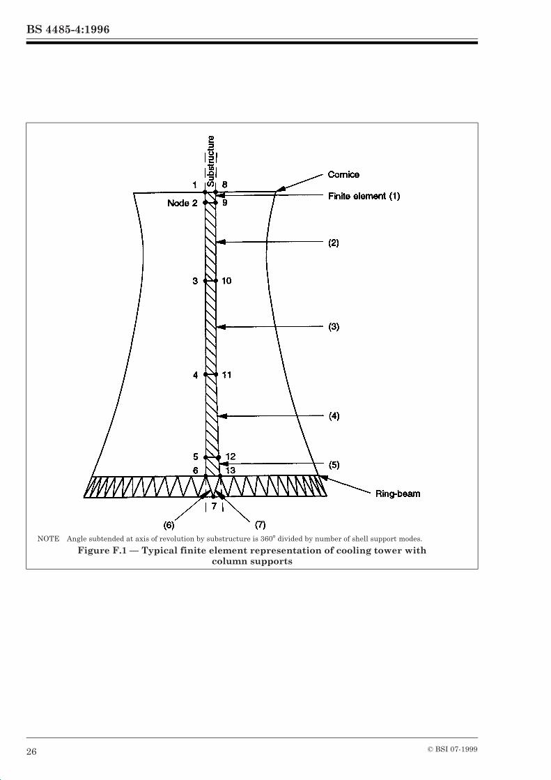
BS 4485-4:1996
26 © BSI 07-1999
NOTE Angle subtended at axis of revolution by substructure is 360° divided by number of shell support modes.
Figure F.1 — Typical finite element representation of cooling tower withcolumn supports
BS 4485-4:1996
© BSI 07-1999 27
List of references
Normative references
BSI publicationsBRITISH STANDARDS INSTITUTION, London
BS 12:1991, Specification for Portland cement. BS 144, Wood preservation using coal tar creosotes. BS 690, Asbestos-cement slates and sheets. BS 690-2:1981, Specification for asbestos-cement and cellulose-asbestos-cement flat sheets. BS 690-5:1975, Lining sheets and panels. BS 729:1971, Specification for hot dip galvanized coatings on iron and steel articles. BS 882:1992, Specification for aggregates from natural sources for concrete. BS 1224:1970, Specification for electroplated coatings of nickel and chromium. BS 1452:1990, Specification for flake graphite cast iron. BS 1501, Steels for pressure purposes. BS 1501-3:1990, Specification for corrosion- and heat-resisting steels: plates, sheet and strip. BS 1615:1987, Method for specifying anodic oxidation coatings on aluminium and its alloys. BS 1706:1990, Method for specifying electroplated coatings of zinc and cadmium on iron and steel. BS 3382, Specification for electroplated coatings on threaded components. BS 3496:1989, Specification for E glass fibre chopped strand mat for reinforcement of polyester and other liquid laminating systems. BS 3572:1986, Specification for access fittings for chimneys and other high structures in concrete or brick work. BS 3656:1981, Specification for asbestos-cement pipes, joints and fittings for sewerage and drainage. BS 3691:1990, Specification for E glass fibre rovings for reinforcement of polyester and epoxy resin systems. BS 3749:1991, Specification for E glass fibre woven roving fabrics for the reinforcement of polyester and epoxy resin systems. BS 3892, Pulverized-fuel ash. BS 3892-1:1993, Specification for pulverized-fuel ash for use with Portland cement. BS 4027:1991, Specification for sulfate-resisting Portland cement. BS 4211:1994, Specification for ladders for permanent access to chimneys, other high structures, silos and bins. BS 4921:1988, Specification for sherardized coatings on iron or steel. BS 4978:1988, Specification for softwood grades for structural use. BS 5075, Concrete admixtures. BS 5268, Structural use of timber. BS 5268-2:1991, Code of practice for permissible stress design, materials and workmanship. BS 5268-5:1989, Code of practice for the preservative treatments of structural timber. BS 5395, Stairs, ladders and walkways. BS 5395-3:1985, Code of practice for the design of industrial type stairs, permanent ladders and walkways. BS 5480:1990, Specification for glass reinforced plastics (GRP) pipes, joints and fittings for use for water supply or sewerage. BS 5493:1977, Code of practice for protective coating of iron and steel structures against corrosion. BS 5556:1978, Specification for general requirements for dimensions and pressure ratings for pipe of thermoplastics materials (metric series). BS 5589:1989, Code of practice for preservation of timber. BS 5606:1990, Guide to accuracy in building. BS 5911, Precast concrete pipes, fittings and ancillary products.
BS 4485-4:1996
© BSI 07-199928
BS 5911-101:1992, Specification for glass composite concrete (GCC) pipes and fittings with flexible joints Specification for ogee pipes and fittings (including perforated). BS 5911-110:1988, Specification for ogee pipes and fittings (including perforated). BS 5950, Structural use of steelwork in building. BS 6100, Glossary of building and civil engineering terms. BS 6180:1995, Code of practice for barriers in and about buildings. BS 6399, Loading for buildings. BS 6399-1:1984, Code of practice for dead and imposed loads. BS 6399-2:1995, Code of practice for wind loading. BS 6651:1992, Code of practice for protection of structures against lightning. BS 6681:1986, Specification for malleable cast iron. BS 8004:1986, Code of practice for foundations. BS 8007:1987, Code of practice for design of concrete structures for retaining aqueous liquids. BS 8110, Structural use of concrete. BS 8110-1:1985, Code of practice for design and construction. BS 8110-2:1985, Code of practice for special circumstances. BS 8118:1991, Structural use of aluminium. BS EN 385:1995, Finger jointed structural timber — Performance requirements and minimum production requirements. BS EN 512:1995, Fibre-cement products — Pressure pipes and joints. BS EN 10028, Specification for flat products made of steels for pressure purposes. BS EN 10028-1:1993, General requirements. BS EN 10028-2:1993, Non-alloy and alloy steels with specified elevated temperature properties. BS EN 10028-3:1993, Weldable fine grain steels, normalized. BS EN 10029:1991, Specification for tolerances on dimensions, shape and mass for hot rolled steel plates 3 mm thick or above.
Informative references
BSI publicationsBRITISH STANDARDS INSTITUTION, London
BS 4485-3:1988, Code of practice for thermal and functional design. BS 7773:1995, Code of practice for cleaning and preparation of metal surfaces. DD 76, Precast concrete pipes of composite construction. DD 76-2:1983, Precast concrete pipes strengthened by chopped zinc-coated steel fibres.
Other references
[1] GREAT BRITAIN. Reservoirs Act, 1975. London: HMSO.[2] GREAT BRITAIN. Control of Substances Hazardous to Health Regulations; 1988. London: HMSO.[3] DIVER, M., and PATERSON, A.C. Large cooling towers, the present trend, The Structural Engineer, 1977, 10(55).[4] NIEMANN, H.J., and ZERNA, W. Impact of research on development of large cooling towers. Enging. Struct., 1986, 8(4), 74–86.[5] FAILKOW, M.N. Design and capacity evaluation of reinforced concrete shell membranes, ACI Journal, Nov–Dec 1985, Title No. 82078.[6] MORLEY, C.T., and GULVANESSIAN, M. Optimum reinforcement of concrete slab elements, Proceedings of the Institution of Civil Engineers, Part 2, 1977, 63(6), 441–454.[7] GUPTA, A.K. Combined membrane and flexural reinforcement in plates and shells, ASCE, Jnl. Strut. Div., 1986, 112(3), 550–557.
BS 4485-4:1996
© BSI 07-1999
[8] NIEMANN, H.J. Reliability of current design methods for wind induced stresses. In: Proceedings of 2nd international symposium on natural draught cooling towers, Bochum, Germany: Ruhr-Universität, 5–7 September 1984, 119–135.[9] KOPPER, H.D. Extreme loading effects on cooling towers, In: Proceedings of 2nd international symposium on natural draught cooling towers, Bochum, Germany: Ruhr-Universität, 5–7 September 1984, 119–135.[10] SAGEAU, J.F., and ROBERT, M. Wind effects on high cooling towers, In: Proceedings of 2nd international symposium on natural draught cooling towers, Bochum, Germany: Ruhr-Universität, 5–7 September 1984.[11] COOK, N.J. The designers guide to wind loading of building structures Part 1, BRE, Butterworths 1985.[12] ARMITT, J. Effect of surface roughness and free stream turbulence on the flow around a model cooling tower at critical Reynolds Numbers, In: Symposium on Wind Effects on Building and Structures, Loughborough, England, April 1968, Paper 6.[13] ABU-SITTA, S.H., and HASHISH, M.G. Response of hyperbolic cooling towers to turbulent wind, ASCE, Jnl. Struct. Div., 1974, 100(ST5), 1037–1051.[14] ARMITT, J. Wind loading on cooling towers, ASCE, Jnl. Struct. Div, 1980, 106(ST3), 623–641.[15] DAVENPORT, A.G., and ISYUMOV, N. Natural draught cooling towers — Ferrybridge and after, In: Proc. Conference ICE London, 12 June 1967, Discussion Session III.[16] ISYUMOV, N., ABU-SITTA, S.H., and DAVENPORT, A.G. Approaches to the design of hyperbolic cooling towers against the dynamic action of wind and earthquake, In: IASS symposium on hyperbolic cooling towers, Brussels, May 1971.[17] Report of the committee of inquiry into the collapse of cooling towers at Ferrybridge on Monday 1 November 1965, CEGB, London.[18] THOMAS, D.L. Dynamics of rotationally periodic structures, Int. Jnl. Num. Meth. Eng., 1979, 14, 81–102.[19] NELSON, R.L. Analyses of cooling tower dynamics, Jnl. Sound and Vibration, 1981, 79 (4), 501–518, 1981.[20] FRICKER, A.J. An assessment of the role of geometric imperfections in the collapse of the Fiddlers Ferry cooling tower, In: Seventh international conference on Wind. Eng., Aachen, W. Germany: July 6–10, 1987.
Bibliography
[21] Natural draught cooling towers — Ferrybridge and after, In: Proc. Conf. ICE London, 12 June 1967.[22] ABU-SITTA, S.H., and HASHISH, M.G. Dynamic wind stresses in hyperbolic cooling towers, ASCE, Jnl. Struct. Div., 1973, 99(ST9), 1823–1835.[23] NIEMANN, H.J. Wind effects on cooling tower shells, ASCE, Jnl. Struct. Div, 1980, 106 (ST3), 643–661.
BS 4485-4:1996
BSI389 Chiswick High RoadLondonW4 4AL
BSI — British Standards InstitutionBSI is the independent national body responsible for preparing British Standards. It presents the UK view on standards in Europe and at the international level. It is incorporated by Royal Charter.
Revisions
British Standards are updated by amendment or revision. Users of British Standards should make sure that they possess the latest amendments or editions.
It is the constant aim of BSI to improve the quality of our products and services. We would be grateful if anyone finding an inaccuracy or ambiguity while using this British Standard would inform the Secretary of the technical committee responsible, the identity of which can be found on the inside front cover. Tel: 020 8996 9000. Fax: 020 8996 7400.
BSI offers members an individual updating service called PLUS which ensures that subscribers automatically receive the latest editions of standards.
Buying standards
Orders for all BSI, international and foreign standards publications should be addressed to Customer Services. Tel: 020 8996 9001. Fax: 020 8996 7001.
In response to orders for international standards, it is BSI policy to supply the BSI implementation of those that have been published as British Standards, unless otherwise requested.
Information on standards
BSI provides a wide range of information on national, European and international standards through its Library and its Technical Help to Exporters Service. Various BSI electronic information services are also available which give details on all its products and services. Contact the Information Centre. Tel: 020 8996 7111. Fax: 020 8996 7048.
Subscribing members of BSI are kept up to date with standards developments and receive substantial discounts on the purchase price of standards. For details of these and other benefits contact Membership Administration. Tel: 020 8996 7002. Fax: 020 8996 7001.
Copyright
Copyright subsists in all BSI publications. BSI also holds the copyright, in the UK, of the publications of the international standardization bodies. Except as permitted under the Copyright, Designs and Patents Act 1988 no extract may be reproduced, stored in a retrieval system or transmitted in any form or by any means – electronic, photocopying, recording or otherwise – without prior written permission from BSI.
This does not preclude the free use, in the course of implementing the standard, of necessary details such as symbols, and size, type or grade designations. If these details are to be used for any other purpose than implementation then the prior written permission of BSI must be obtained.
If permission is granted, the terms may include royalty payments or a licensing agreement. Details and advice can be obtained from the Copyright Manager. Tel: 020 8996 7070.