water desalination: designing a seawater purification system · 2018-03-21 · water desalination:...
TRANSCRIPT
Water Desalination: Designing a Seawater Purification
System
1
Water Desalination: Designing a Seawater Purification
System
A Major Qualifying Project Report Submitted to the Faculty of
Worcester Polytechnic Institute In partial fulfillment of the requirements for the
Degree of Bachelor of Science In the fields of Chemical and Mechanical Engineering
Submitted By: Submitted to:
Spencer Austin Worcester Polytechnic Institute
Trevor Gehring Project Advisors:
Michael Wilkinson Prof. Stephen Kmiotek, WPI
Benjamin Zogby Prof. Robert Daniello, WPI
This report represents the work of four WPI undergraduate students submitted to the faculty as evidence of completion of a degree requirement. WPI routinely publishes these reports on its website without editorial or peer review. For more information about the projects program at WPI, please see http://www.wpi.edu/Acvademics/Projects.
2
Abstract
Water is a fundamental need for all living things. The goal of our project was to design, prototype, and test a portable water desalination unit capable of producing drinkable water in emergency situations. The team elected to use a boiler-condenser system with a thermoelectric dehumidifying unit. This system is unlike others on the market because it is able to produce a higher volume of water using any source, and is personal sized and portable. Testing of the system resulted in the conversion of 1,000 mL of 35 ppm salt water to an average of 820 mL of drinkable water in 40 minutes. This corresponds to an efficiency of 82.0%, and a drinking water production rate of 20.5 mL/min. Being the first apparatus of its kind, there are many possibilities for improvements. The team envisions the system to be powered by a portable source such as solar or battery.
3
Acknowledgements Ryan Cooney - Majoring in Electrical and Computer Engineering, Ryan provided the team with arduino programming help and circuitry design. Professors Kmiotek and Daniello - As project advisors, Professors Stephen Kmiotek and Robert Daniello provided insight and feedback related to all stages of design and construction of the project. Tom Partington - Tom machined parts for the team, including steam nozzles and taps, and provided equipment such as hose clamps and tubing, as well as gave advice regarding the construction of the steam transport assembly. Peter Hefty - Peter provided the team with project supplies including thermal paste, wiring, and allowed the team to complete work in his ME3901 lab workspace. Worcester Polytechnic Institute -
4
Contents Abstract 3
Acknowledgements 4
Contents 5
Introduction 6
Background 7 Hurricanes 7 Drinkable Standards 7 Water Purification Methods 8
Methodology 9 Design Specifications 9 Operation 9 Process Flowsheet 10 Prototype 12 Components List 17 Testing Methods 19
Results and Analysis 20 Apparatus Performance 20
Conclusions and Recommendation 21 Maintenance and Safety 21 Recommendations 21 Overall Conclusion 22
References 23
Appendices 24 Appendix A: Boiling timelines for electric kettle 25 Appendix B: Boiling curves for electric kettle 26 Appendix C: Solidworks Modeling 27
5
Introduction
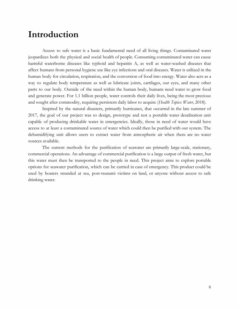
Access to safe water is a basic fundamental need of all living things. Contaminated water jeopardizes both the physical and social health of people. Consuming contaminated water can cause harmful waterborne diseases like typhoid and hepatitis A, as well as water-washed diseases that affect humans from personal hygiene use like eye infections and oral diseases. Water is utilized in the human body for circulation, respiration, and the conversion of food into energy. Water also acts as a way to regulate body temperature as well as lubricate joints, cartilages, our eyes, and many other parts to our body. Outside of the need within the human body, humans need water to grow food and generate power. For 1.1 billion people, water controls their daily lives, being the most precious and sought after commodity, requiring persistent daily labor to acquire (Health Topics: Water, 2018).
Inspired by the natural disasters, primarily hurricanes, that occurred in the late summer of 2017, the goal of our project was to design, prototype and test a portable water desalination unit capable of producing drinkable water in emergencies. Ideally, those in need of water would have access to at least a contaminated source of water which could then be purified with our system. The dehumidifying unit allows users to extract water from atmospheric air when there are no water sources available.
The current methods for the purification of seawater are primarily large-scale, stationary, commercial operations. An advantage of commercial purification is a large output of fresh water, but this water must then be transported to the people in need. This project aims to explore portable options for seawater purification, which can be carried in case of emergency. This product could be used by boaters stranded at sea, post-tsunami victims on land, or anyone without access to safe drinking water.
6
Background
Hurricanes
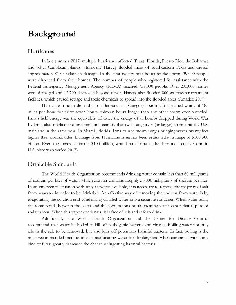
In late summer 2017, multiple hurricanes affected Texas, Florida, Puerto Rico, the Bahamas and other Caribbean islands. Hurricane Harvey flooded most of southeastern Texas and caused approximately $180 billion in damage. In the first twenty-four hours of the storm, 39,000 people were displaced from their homes. The number of people who registered for assistance with the Federal Emergency Management Agency (FEMA) reached 738,000 people. Over 200,000 homes were damaged and 12,700 destroyed beyond repair. Harvey also flooded 800 wastewater treatment facilities, which caused sewage and toxic chemicals to spread into the flooded areas (Amadeo 2017).
Hurricane Irma made landfall on Barbuda as a Category 5 storm. It sustained winds of 185 miles per hour for thirty-seven hours; thirteen hours longer than any other storm ever recorded. Irma’s held energy was the equivalent of twice the energy of all bombs dropped during World War II. Irma also marked the first time in a century that two Category 4 (or larger) storms hit the U.S. mainland in the same year. In Miami, Florida, Irma caused storm surges bringing waves twenty feet higher than normal tides. Damage from Hurricane Irma has been estimated at a range of $100-300 billion. Even the lowest estimate, $100 billion, would rank Irma as the third most costly storm in U.S. history (Amadeo 2017).
Drinkable Standards The World Health Organization recommends drinking water contain less than 60 milligrams
of sodium per liter of water, while seawater contains roughly 35,000 milligrams of sodium per liter. In an emergency situation with only seawater available, it is necessary to remove the majority of salt from seawater in order to be drinkable. An effective way of removing the sodium from water is by evaporating the solution and condensing distilled water into a separate container. When water boils, the ionic bonds between the water and the sodium ions break, creating water vapor that is pure of sodium ions. When this vapor condenses, it is free of salt and safe to drink.
Additionally, the World Health Organization and the Center for Disease Control recommend that water be boiled to kill off pathogenic bacteria and viruses. Boiling water not only allows the salt to be removed, but also kills off potentially harmful bacteria. In fact, boiling is the most recommended method of decontaminating water for drinking and when combined with some kind of filter, greatly decreases the chance of ingesting harmful bacteria
7

Water Purification Methods In the early stages of the project, we researched and examined multiple methods of water
purification before ultimately electing a distillation process. Other methods included membrane separation, reverse osmosis and chemical treatment. Although each method has its advantages and disadvantages, distillation is commonly regarded as one of the most effective methods in purifying liquids. One of the disadvantages of distillation is that it typically has a high energy requirement, which explains why converting our project to a portable energy source is difficult.
Chemical treatment is primarily used to treat water infested with bacteria, parasites and other impurities. One downfall of the use of chemicals is that you can often taste them in the water. Additionally, using too many chemicals in the water can make the consumer ill, while not using enough will prevent all of the impurities from being removed.
Reverse osmosis is similar to membrane separation except that it occurs in the direction opposite of natural osmosis. It is most commonly used in the purification of drinking water, but we found it not to be an achievable method for our project primarily due to the extreme amount of pressure that needs to be applied to overcome natural osmosis. The pressure requirement for reverse osmosis can be anywhere from 25-40 bar which is approximately 25-40 times atmospheric pressure (Stoughton 2013). Achieving such a high pressure combined with the necessary membrane to separate the salt from the water would have required a lot of energy.
8
Methodology
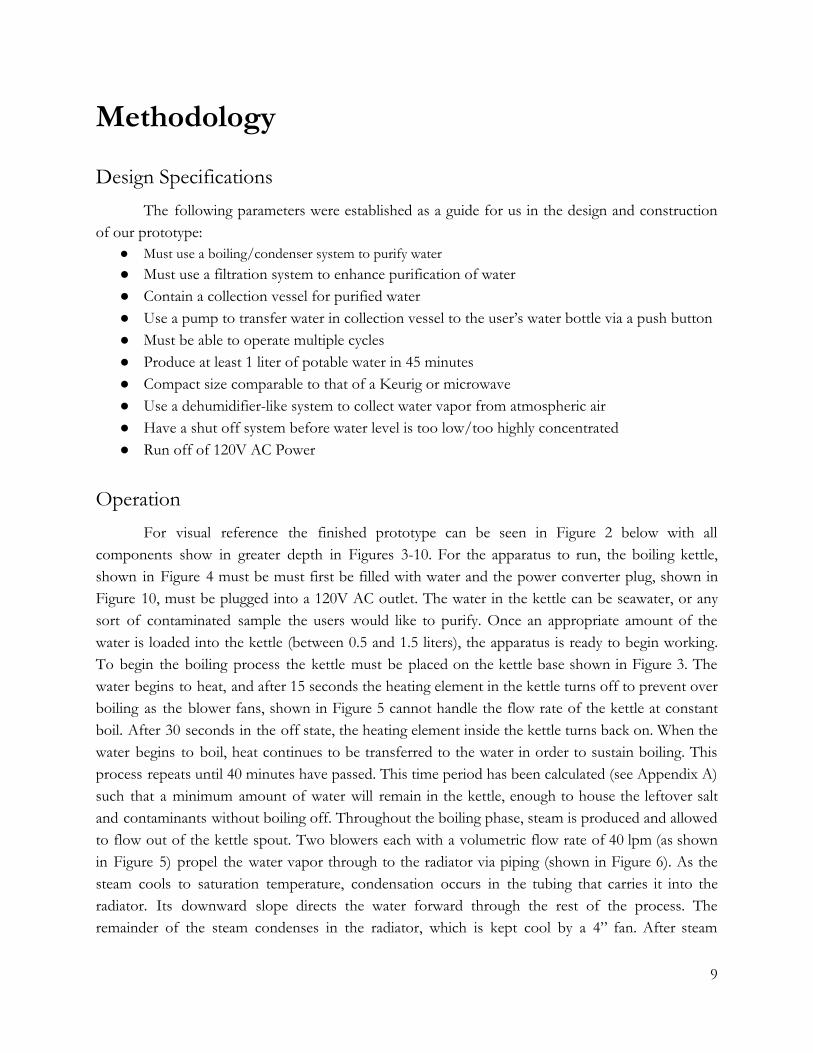
Design Specifications The following parameters were established as a guide for us in the design and construction
of our prototype: ● Must use a boiling/condenser system to purify water ● Must use a filtration system to enhance purification of water ● Contain a collection vessel for purified water ● Use a pump to transfer water in collection vessel to the user’s water bottle via a push button ● Must be able to operate multiple cycles ● Produce at least 1 liter of potable water in 45 minutes ● Compact size comparable to that of a Keurig or microwave ● Use a dehumidifier-like system to collect water vapor from atmospheric air ● Have a shut off system before water level is too low/too highly concentrated ● Run off of 120V AC Power
Operation
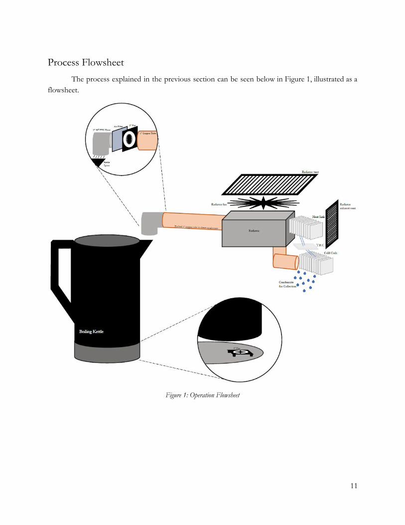
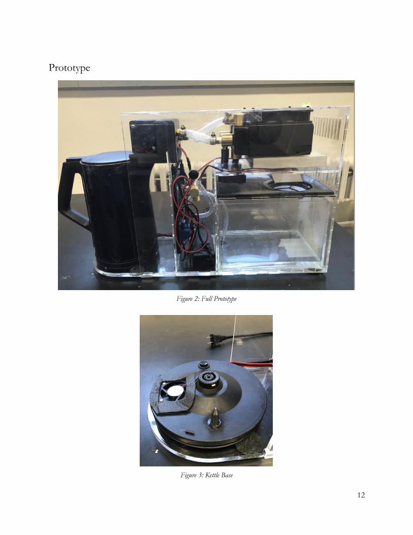
For visual reference the finished prototype can be seen in Figure 2 below with all components show in greater depth in Figures 3-10. For the apparatus to run, the boiling kettle, shown in Figure 4 must be must first be filled with water and the power converter plug, shown in Figure 10, must be plugged into a 120V AC outlet. The water in the kettle can be seawater, or any sort of contaminated sample the users would like to purify. Once an appropriate amount of the water is loaded into the kettle (between 0.5 and 1.5 liters), the apparatus is ready to begin working. To begin the boiling process the kettle must be placed on the kettle base shown in Figure 3. The water begins to heat, and after 15 seconds the heating element in the kettle turns off to prevent over boiling as the blower fans, shown in Figure 5 cannot handle the flow rate of the kettle at constant boil. After 30 seconds in the off state, the heating element inside the kettle turns back on. When the water begins to boil, heat continues to be transferred to the water in order to sustain boiling. This process repeats until 40 minutes have passed. This time period has been calculated (see Appendix A) such that a minimum amount of water will remain in the kettle, enough to house the leftover salt and contaminants without boiling off. Throughout the boiling phase, steam is produced and allowed to flow out of the kettle spout. Two blowers each with a volumetric flow rate of 40 lpm (as shown in Figure 5) propel the water vapor through to the radiator via piping (shown in Figure 6). As the steam cools to saturation temperature, condensation occurs in the tubing that carries it into the radiator. Its downward slope directs the water forward through the rest of the process. The remainder of the steam condenses in the radiator, which is kept cool by a 4” fan. After steam
9
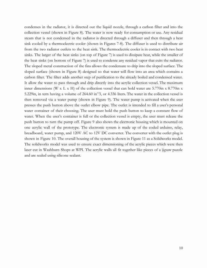
condenses in the radiator, it is directed out the liquid nozzle, through a carbon filter and into the collection vessel (shown in Figure 8). The water is now ready for consumption or use. Any residual steam that is not condensed in the radiator is directed through a diffuser and then through a heat sink cooled by a thermoelectric cooler (shown in Figures 7-8). The diffuser is used to distribute air from the two radiator outlets to the heat sink. The thermoelectric cooler is in contact with two heat sinks. The larger of the heat sinks (on top of Figure 7) is used to dissipate heat, while the smaller of the heat sinks (on bottom of Figure 7) is used to condense any residual vapor that exits the radiator. The sloped metal construction of the fins allows the condensate to drip into the sloped surface. The sloped surface (shown in Figure 8) designed so that water will flow into an area which contains a carbon filter. The filter adds another step of purification to the already boiled and condensed water. It allow the water to pass through and drip directly into the acrylic collection vessel. The maximum inner dimensions (W x L x H) of the collection vessel that can hold water are 5.770in x 8.770in x 5.229in, in tern having a volume of 264.60 in^3, or 4.336 liters. The water in the collection vessel is then removed via a water pump (shown in Figure 9). The water pump is activated when the user presses the push button above the outlet elbow pipe. The outlet is intended to fill a user’s personal water container of their choosing. The user must hold the push button to keep a constant flow of water. When the user’s container is full or the collection vessel is empty, the user must release the push button to turn the pump off. Figure 9 also shows the electronic housing which is mounted on one acrylic wall of the prototype. The electronic system is made up of the coded arduino, relay, breadboard, water pump, and 120V AC to 12V DC converter. The converter with the outlet plug is shown in Figure 10. The overall housing of the system is shown in Figure 11 as a Solidworks model. The solidworks model was used to ensure exact dimensioning of the acrylic pieces which were then laser cut in Washburn Shops at WPI. The acrylic walls all fit together like pieces of a jigsaw puzzle and are sealed using silicone sealant.
10
Process Flowsheet The process explained in the previous section can be seen below in Figure 1, illustrated as a
flowsheet.
Figure 1: Operation Flowsheet
11
Prototype
Figure 2: Full Prototype
Figure 3: Kettle Base
12
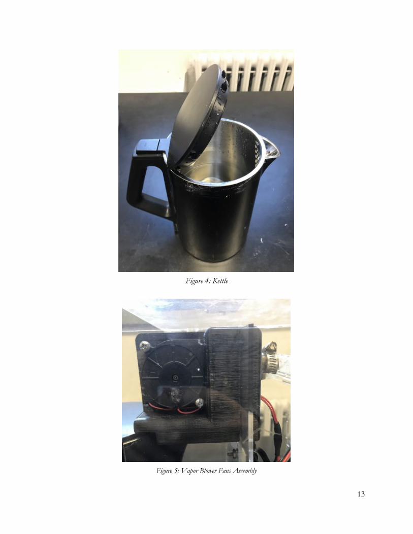
Figure 4: Kettle
Figure 5: Vapor Blower Fans Assembly
13
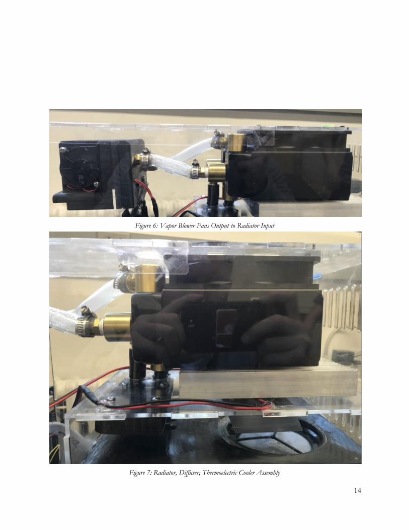
Figure 6: Vapor Blower Fans Output to Radiator Input
Figure 7: Radiator, Diffuser, Thermoelectric Cooler Assembly
14
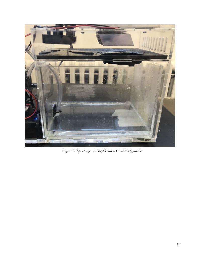
Figure 8: Sloped Surface, Filter, Collection Vessel Configuration
15
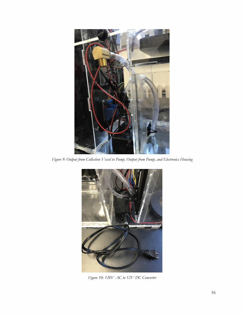
Figure 9: Output from Collection Vessel to Pump, Output from Pump, and Electronics Housing
Figure 10: 120V AC to 12V DC Converter
16
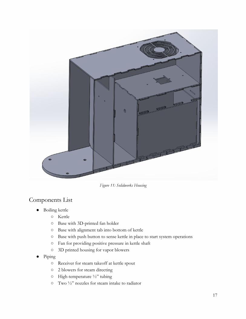
Figure 11: Solidworks Housing
Components List ● Boiling kettle
○ Kettle ○ Base with 3D-printed fan holder ○ Base with alignment tab into bottom of kettle ○ Base with push button to sense kettle in place to start system operations ○ Fan for providing positive pressure in kettle shaft ○ 3D printed housing for vapor blowers
● Piping ○ Receiver for steam takeoff at kettle spout ○ 2 blowers for steam directing ○ High-temperature ½” tubing ○ Two ½” nozzles for steam intake to radiator
17
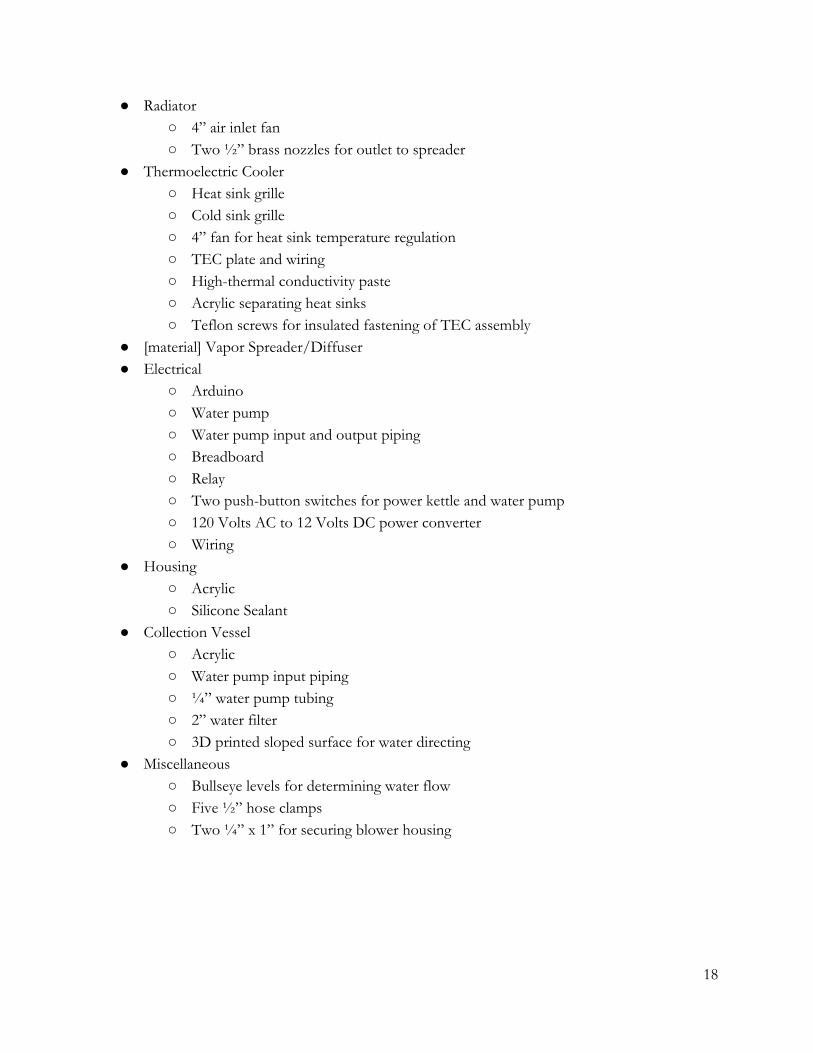
● Radiator ○ 4” air inlet fan ○ Two ½” brass nozzles for outlet to spreader
● Thermoelectric Cooler ○ Heat sink grille ○ Cold sink grille ○ 4” fan for heat sink temperature regulation ○ TEC plate and wiring ○ High-thermal conductivity paste ○ Acrylic separating heat sinks ○ Teflon screws for insulated fastening of TEC assembly
● [material] Vapor Spreader/Diffuser ● Electrical
○ Arduino ○ Water pump ○ Water pump input and output piping ○ Breadboard ○ Relay ○ Two push-button switches for power kettle and water pump ○ 120 Volts AC to 12 Volts DC power converter ○ Wiring
● Housing ○ Acrylic ○ Silicone Sealant
● Collection Vessel ○ Acrylic ○ Water pump input piping ○ ¼” water pump tubing ○ 2” water filter ○ 3D printed sloped surface for water directing
● Miscellaneous ○ Bullseye levels for determining water flow ○ Five ½” hose clamps ○ Two ¼” x 1” for securing blower housing
18
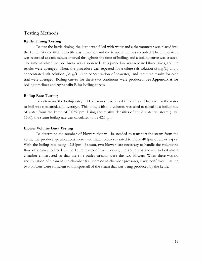
Testing Methods Kettle Timing Testing
To test the kettle timing, the kettle was filled with water and a thermometer was placed into the kettle. At time t=0, the kettle was turned on and the temperature was recorded. The temperature was recorded at each minute interval throughout the time of boiling, and a boiling curve was created. The time at which the boil broke was also noted. This procedure was repeated three times, and the results were averaged. Then, the procedure was repeated for a dilute salt solution (5 mg/L) and a concentrated salt solution (35 g/L - the concentration of seawater), and the three results for each trial were averaged. Boiling curves for these two conditions were produced. See Appendix A for boiling timelines and Appendix B for boiling curves. Boilup Rate Testing
To determine the boilup rate, 1.0 L of water was boiled three times. The time for the water to boil was measured, and averaged. This time, with the volume, was used to calculate a boilup rate of water from the kettle of 0.025 lpm. Using the relative densities of liquid water vs. steam (1 vs. 1700), the steam boilup rate was calculated to be 42.5 lpm. Blower Volume Duty Testing
To determine the number of blowers that will be needed to transport the steam from the kettle, the product specifications were used. Each blower is rated to move 40 lpm of air or vapor. With the boilup rate being 42.5 lpm of steam, two blowers are necessary to handle the volumetric flow of steam produced by the kettle. To confirm this duty, the kettle was allowed to boil into a chamber constructed so that the sole outlet streams were the two blowers. When there was no accumulation of steam in the chamber (i.e. increase in chamber pressure), it was confirmed that the two blowers were sufficient to transport all of the steam that was being produced by the kettle.
19
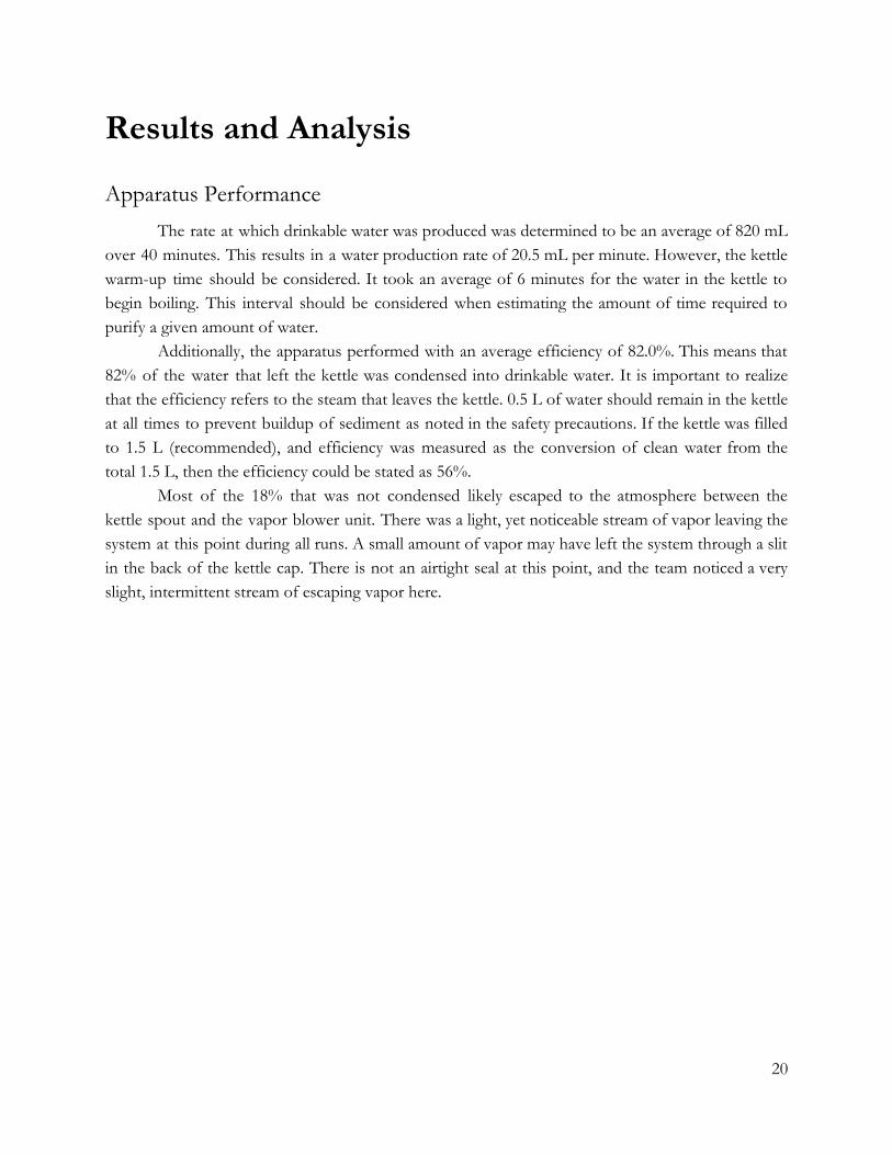
Results and Analysis
Apparatus Performance The rate at which drinkable water was produced was determined to be an average of 820 mL
over 40 minutes. This results in a water production rate of 20.5 mL per minute. However, the kettle warm-up time should be considered. It took an average of 6 minutes for the water in the kettle to begin boiling. This interval should be considered when estimating the amount of time required to purify a given amount of water.
Additionally, the apparatus performed with an average efficiency of 82.0%. This means that 82% of the water that left the kettle was condensed into drinkable water. It is important to realize that the efficiency refers to the steam that leaves the kettle. 0.5 L of water should remain in the kettle at all times to prevent buildup of sediment as noted in the safety precautions. If the kettle was filled to 1.5 L (recommended), and efficiency was measured as the conversion of clean water from the total 1.5 L, then the efficiency could be stated as 56%.
Most of the 18% that was not condensed likely escaped to the atmosphere between the kettle spout and the vapor blower unit. There was a light, yet noticeable stream of vapor leaving the system at this point during all runs. A small amount of vapor may have left the system through a slit in the back of the kettle cap. There is not an airtight seal at this point, and the team noticed a very slight, intermittent stream of escaping vapor here.
20
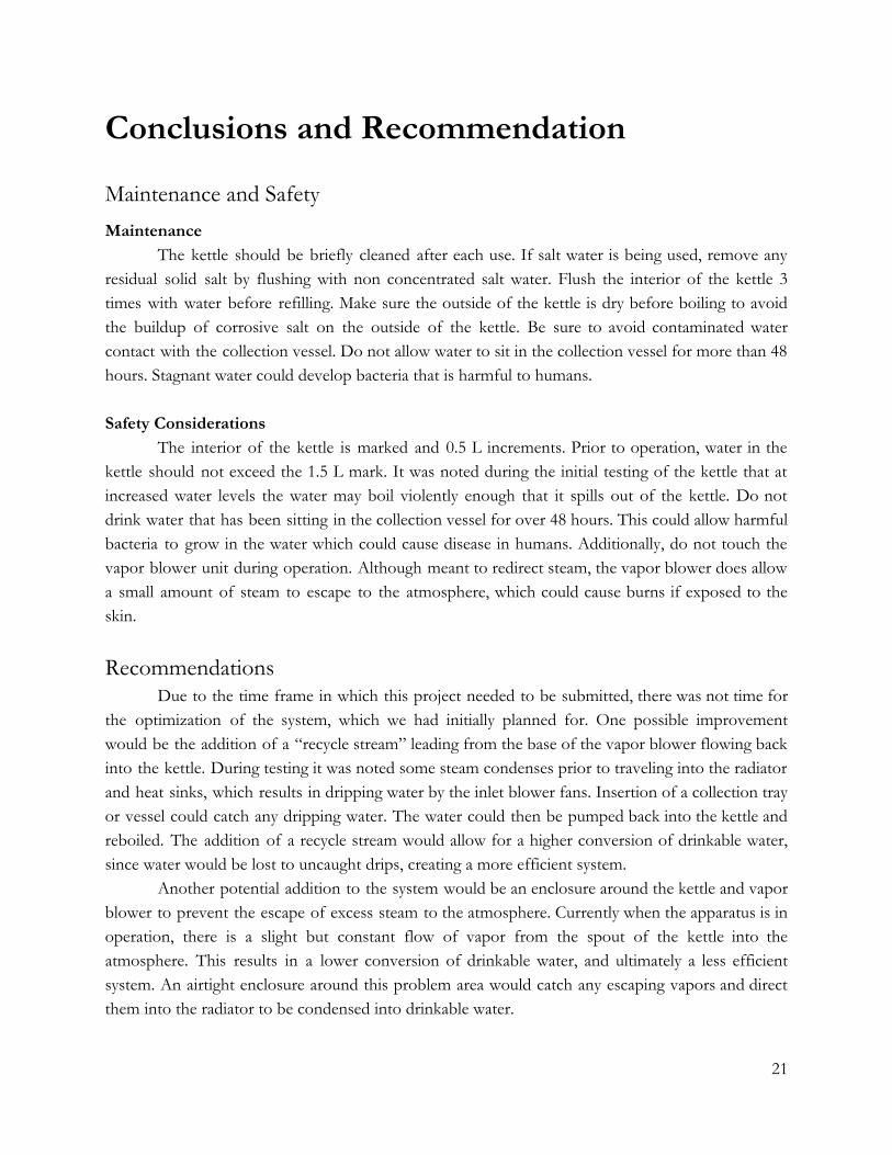
Conclusions and Recommendation
Maintenance and Safety Maintenance
The kettle should be briefly cleaned after each use. If salt water is being used, remove any residual solid salt by flushing with non concentrated salt water. Flush the interior of the kettle 3 times with water before refilling. Make sure the outside of the kettle is dry before boiling to avoid the buildup of corrosive salt on the outside of the kettle. Be sure to avoid contaminated water contact with the collection vessel. Do not allow water to sit in the collection vessel for more than 48 hours. Stagnant water could develop bacteria that is harmful to humans. Safety Considerations
The interior of the kettle is marked and 0.5 L increments. Prior to operation, water in the kettle should not exceed the 1.5 L mark. It was noted during the initial testing of the kettle that at increased water levels the water may boil violently enough that it spills out of the kettle. Do not drink water that has been sitting in the collection vessel for over 48 hours. This could allow harmful bacteria to grow in the water which could cause disease in humans. Additionally, do not touch the vapor blower unit during operation. Although meant to redirect steam, the vapor blower does allow a small amount of steam to escape to the atmosphere, which could cause burns if exposed to the skin.
Recommendations Due to the time frame in which this project needed to be submitted, there was not time for
the optimization of the system, which we had initially planned for. One possible improvement would be the addition of a “recycle stream” leading from the base of the vapor blower flowing back into the kettle. During testing it was noted some steam condenses prior to traveling into the radiator and heat sinks, which results in dripping water by the inlet blower fans. Insertion of a collection tray or vessel could catch any dripping water. The water could then be pumped back into the kettle and reboiled. The addition of a recycle stream would allow for a higher conversion of drinkable water, since water would be lost to uncaught drips, creating a more efficient system.
Another potential addition to the system would be an enclosure around the kettle and vapor blower to prevent the escape of excess steam to the atmosphere. Currently when the apparatus is in operation, there is a slight but constant flow of vapor from the spout of the kettle into the atmosphere. This results in a lower conversion of drinkable water, and ultimately a less efficient system. An airtight enclosure around this problem area would catch any escaping vapors and direct them into the radiator to be condensed into drinkable water.
21
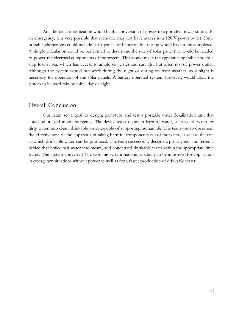
An additional optimization would be the conversion of power to a portable power source. In an emergency, it is very possible that someone may not have access to a 120 V power outlet. Some possible alternatives could include solar panels or batteries, but testing would have to be completed. A simple calculation could be performed to determine the size of solar panel that would be needed to power the electrical components of the system. This would make the apparatus operable aboard a ship lost at sea, which has access to ample salt water and sunlight, but often no AC power outlet. Although the system would not work during the night or during overcast weather, as sunlight is necessary for operation of the solar panels. A battery operated system, however, would allow the system to be used rain or shine, day or night.
Overall Conclusion Our team set a goal to design, prototype and test a portable water desalination unit that
could be utilized in an emergency. The device was to convert harmful water, such as salt water, or dirty water, into clean, drinkable water capable of supporting human life. The team was to document the effectiveness of the apparatus in taking harmful components out of the water, as well as the rate at which drinkable water can be produced. The team successfully designed, prototyped, and tested a device that boiled salt water into steam, and condensed drinkable water within the appropriate time frame. The system converted The working system has the capability to be improved for application in emergency situations without power as well as for a faster production of drinkable water.
22
References Amadeo, Kimberly. (2017, September 15). Hurricane Irma: Facts, Damage, Costs. Retrieved from
https://www.thebalance.com/hurricane-irma-facts-timeline-damage-costs-4150395 Amadeo, Kimberly. (2017, September 30). Hurricane Harvey: Facts, Damage, Costs. Retrieved from
https://www.thebalance.com/hurricane-harvey-facts-damage-costs-4150087
Byrne, Kevin. (30 November, 2017). Why the 2017 Atlantic hurricane season ranks among the top 7 most intense ever recorded. Retrieved from https://www.accuweather.com/en/weather-news/why-the-2017-atlantic-hurricane-season-r anks-among-the-top-7-most-intense-ever-recorded/70003277
Health Topics: Water. (2018). World Health Organization. Retrieved from http://www.who.int/topics/water/en/
Stoughton, KL McMordie. (August 2013). Reverse Osmosis Optimization. Retrieved from https://www.pnnl.gov/main/publications/external/technical_reports/PNNL-22682.pdf
What is Reverse Osmosis? (Retrieved November 2018). Retrieved from https://puretecwater.com/reverse-osmosis/what-is-reverse-osmosis#understanding-reverse-osmosis
23
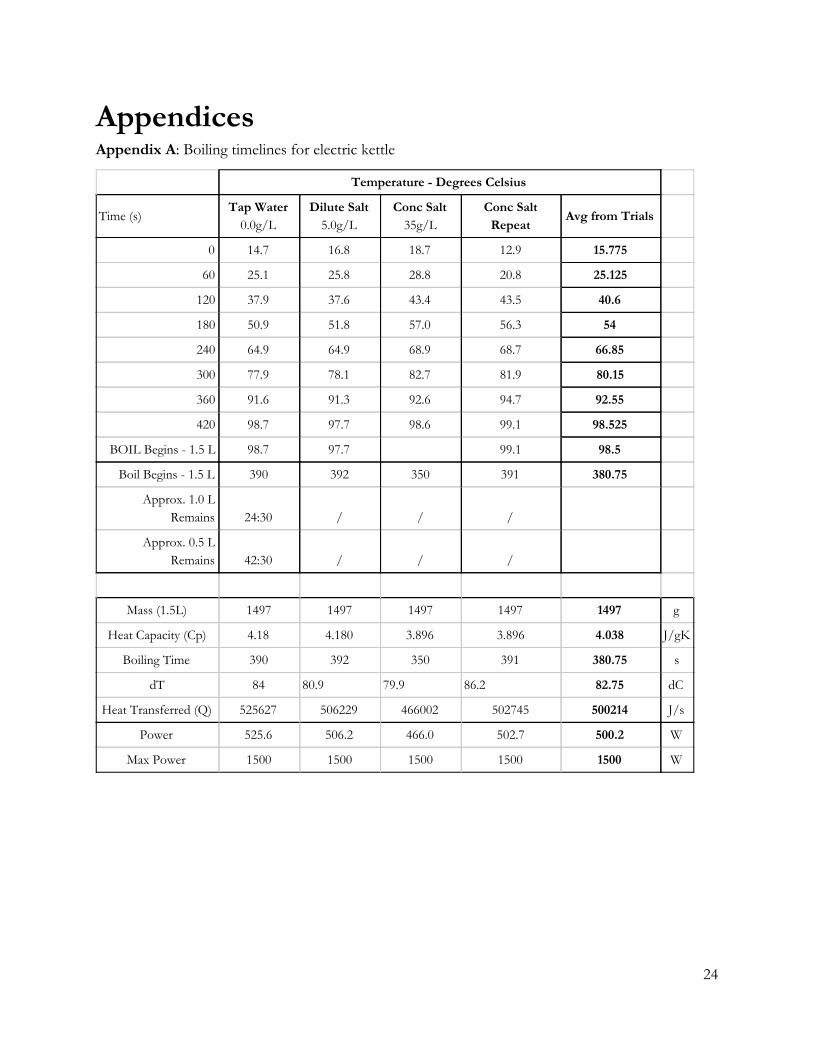
Appendices Appendix A: Boiling timelines for electric kettle
Temperature - Degrees Celsius
Time (s) Tap Water
0.0g/L Dilute Salt
5.0g/L Conc Salt
35g/L Conc Salt
Repeat Avg from Trials
0 14.7 16.8 18.7 12.9 15.775
60 25.1 25.8 28.8 20.8 25.125
120 37.9 37.6 43.4 43.5 40.6
180 50.9 51.8 57.0 56.3 54
240 64.9 64.9 68.9 68.7 66.85
300 77.9 78.1 82.7 81.9 80.15
360 91.6 91.3 92.6 94.7 92.55
420 98.7 97.7 98.6 99.1 98.525
BOIL Begins - 1.5 L 98.7 97.7 99.1 98.5
Boil Begins - 1.5 L 390 392 350 391 380.75
Approx. 1.0 L Remains 24:30 / / /
Approx. 0.5 L Remains 42:30 / / /
Mass (1.5L) 1497 1497 1497 1497 1497 g
Heat Capacity (Cp) 4.18 4.180 3.896 3.896 4.038 J/gK
Boiling Time 390 392 350 391 380.75 s
dT 84 80.9 79.9 86.2 82.75 dC
Heat Transferred (Q) 525627 506229 466002 502745 500214 J/s
Power 525.6 506.2 466.0 502.7 500.2 W
Max Power 1500 1500 1500 1500 1500 W
24
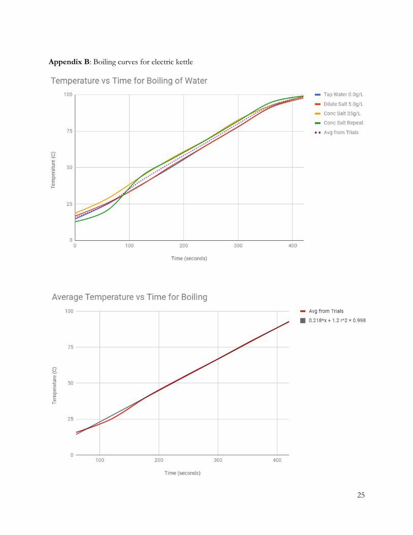
Appendix B: Boiling curves for electric kettle
25
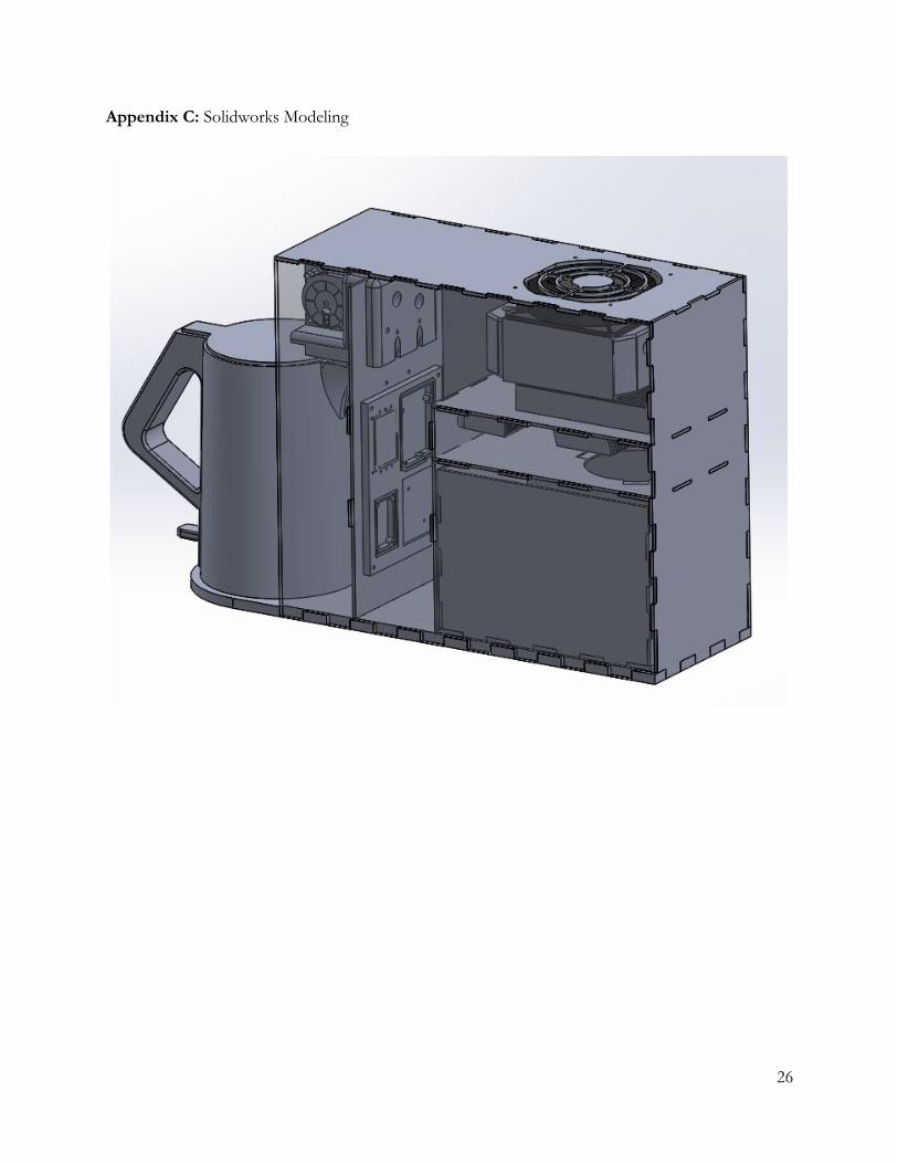
Appendix C: Solidworks Modeling
26