water injection system design for six stroke …umpir.ump.edu.my/id/eprint/4492/1/cd6605_72.pdf ·...
TRANSCRIPT

WATER INJECTION SYSTEM DESIGN FOR SIX STROKE ENGINE
MUHAMAD NURZAMI BIN AB SOTA
Thesis submitted in fulfillment of the requirements
for the award of the degree of
Bachelor of Mechanical Engineering with Automotive Engineering
Faculty of Mechanical Engineering
UNIVERSITI MALAYSIA PAHANG
JUNE 2012
v
ABSTRACT
The engine for automobile is developed rapidly from each year as to increase the
performance and able to decrease the fuel consumption. Various method and concept
had be proposed previously based on mechanism, new attachments and material usage
for the engine. This thesis is about the water injection system design for currently new
six stroke engine as one of development engine method. The objectives of this project
are to design new water injection system and find suitable components that compatible
with this system. This project describes about process for design and fabricated the
water injection system based on selected concept design. Some of concept design were
proposed earlier and compared together. Then, the concept with the good mechanism
and able to built was selected and designed using Solidwork software. The concept was
chosen by considering the capability to operate the system, functionality, area usage and
material or components chosen. This concept is generated from the fuel injection system
for diesel engine where the fuel injection was controlled through fuel pump and
pumping operation driven by rotation of camshaft. Hence, the similar system was
presented here by some component modification in order to produce the six stroke
engine. The complete manufactured water injection system was analyze by testing them
with experimental as to achieve best result. The fabrication process was conducted
following the dimension of modeling design and some modification to the existing
component. The complete water injection system was fabricated successfully and
several analysis tests have been conducted to measure the capability of our system. Two
testing have been made to determine the performance of water pump with different
pressure and amount of water injected by water injector. The result showed that the
injections pump produce different pressure with time duration and plunger pump
compression. The water injector was modified to obtain the suitable opening pressure to
inject specific amount of water into combustion chamber.
vi
ABSTRAK
Pembangunan enjin untuk automobil dengan pesat dari setiap tahun untuk
meningkatkan prestasi dan dapat mengurangkan penggunaan bahan api. Pelbagai
kaedah dan konsep yang telah dicadangkan sebelum ini berdasarkan mekanisme,
pembaharuan baru dan penggunaan bahan sesuai untuk enjin. Tesis ini adalah berkenaan
reka bentuk sistem suntikan air untuk enjin enam lejang yang baru sebagai salah satu
kaedah enjin pembangunan. Objektif projek ini adalah untuk mereka bentuk sistem
suntikan air baru dan mencari komponen yang sesuai yang serasi dengan sistem ini.
Projek ini menerangkan tentang proses reka bentuk dan pembuatan sistem suntikan air
berdasarkan konsep reka bentuk yang dipilih. Beberapa konsep reka bentuk telah
dicadangkan sebelum ini dan dibandingkan bersama. Kemudian, konsep dengan
mekanisme yang baik dan dapat dibina telah dipilih dan direka dengan menggunakan
perisian Solidwork. Konsep itu dipilih dengan mengambil kira keupayaan untuk
mengendalikan sistem, fungsi, kawasan dan penggunaan bahan atau komponen yang
dipilih. Konsep ini dijana dari sistem suntikan minyak untuk enjin diesel, yang mana
suntikan minyak diesel dikawal melalui pam minyak diesel dan pam operasi yang
didorong oleh putaran camshaft. Oleh itu, sistem yang sama telah dibentangkan di sini
dengan beberapa pengubahsuaian komponen untuk menghasilkan enjin enam lejang.
Pembuatan sistem suntikan air lengkap adalah menganalisis dengan menguji mereka
dengan eksperimen untuk mencapai hasil yang terbaik. Proses fabrikasi dijalankan
berdasarkan dimensi reka bentuk pemodelan dan beberapa pengubahsuaian kepada
komponen yang sedia ada. Sistem lengkap suntikan air telah dijalankan dengan berjaya
dan beberapa ujian analisis telah dijalankan untuk mengukur keupayaan sistem ini. Dua
ujian telah dibuat untuk menentukan prestasi pam air dengan tekanan yang berbeza dan
jumlah air yang disuntik oleh air suntikan. Hasilnya menunjukkan bahawa pam suntikan
menghasilkan tekanan yang berbeza dengan tempoh masa dan pam pelekap mampatan.
Suntikan air atau atomizer telah diubahsuai untuk mendapatkan tekanan pembukaan
yang sesuai untuk menyuntik jumlah tentu air ke dalam kebuk pembakaran.

vii
TABLE OF CONTENTS
Page
SUPERVISOR’S DECLARATION ii
STUDENT’S DECLARATION iii
ACKNOWLEDGEMENTS iv
ABSTRACT v
ABSTRAK vi
TABLE OF CONTENTS vii
LIST OF TABLES viii
LIST OF FIGURES ix
LIST OF SYMBOLS x
LIST OF ABBREVIATIONS xi
CHAPTER 1 INTRODUCTION
1.1 Project Background 1
1.2 Problem Statement 2
1.3 Objectives of Project 3
1.4 Scopes of Project 3
CHAPTER 2 LITERATURE REVIEW
2.1 Introduction 4
2.2 Internal Combustion Engine 4
2.3 Types of Stroke Cycle 5
2.4 Engine Efficiency 10
2.5 Water Injection System 11
2.5.1 Water Tank 12

viii
2.5.2 Types of Injection Pump 13
2.5.3 Water Injector 16
2.5.4 Water Injection Connection Pipe 17
CHAPTER 3 WATER INJECTION SYSTEM DESIGN
3.1 Introduction 18
3.2 Methodology Chart 18
3.3 Conceptualization 20
3.3.1 Determine Required Mechanism 20
3.3.2 Concept Development
3.3.3 Concept Selection
21
22
3.4 Design Development 23
3.5 Materials and Components 23
3.6 Sample Calculation 28
3.7 Fabrication Process 30
3.8 Analysis Test 34
CHAPTER 4 RESULTS AND DISCUSSIONS
4.1 Introduction 37
4.2 Fabricated Part 38
4.3 Water Injection System Operation 41
4.4 Result Analysis 43
CHAPTER 5 CONCLUSION AND RECOMMENDATIONS
5.1 Introduction 46
5.2 Conclusion 46
5.3 Recommendations 47
REFFERENCES 48

ix
APPENDICES
A Main Housing 50
B Plunger Housing 51
C Spring Housing 52
D Housing Assemble 53
E Housing Stand Assemble 54
F Stand Part A 55
G Stand Part B 56
H Stand Base 57

x
LIST OF TABLES
Table No. Title Page
2.1 Specification of common diesel fuel pump 15
3.1 The specification of water injector (atomizer) 25
4.1 Experimental results for nozzle opening pressure (NOP) with different
shim thickness
42
4.2 The condition of injection timing volume for different nozzle opening
pressure (NOP)
43
4.3 The experimental results to determine amount of water injected 43

xi
LIST OF FIGURES
Figure
No.
Title Page
2.1 The two stroke cycle operation 5
2.2 The four stroke cycle operation 6
2.3 The operation of six stroke cycle 7
2.4 Schematic of typical intake and exhaust valve events for a petrol
engine Otto cycle
8
2.5 Schematic of pressure vs. volume for a typical petrol engine Otto
cycle
8
2.6 Schematic of typical intake and exhaust valve events for the six stroke
engine cycle
9
2.7 Schematic of pressure vs. volume for a six stroke engine cycle 9
2.8 Water injection system 11
2.9 Example of water tank 12
2.10 Configuration components in type of mechanical fuel pump 13
2.11 Gear pump 14
2.12 Diagram of a single piston reciprocating pump 15
2.13 Types of water injector 16
2.14 The fuel injection pipes 17
3.1 Methodology chart process 19
3.2 The illustration for concept A 21
3.3 The illustration for Concept B 22
3.4 Main engine model Mitsubishi G1200L 24
3.5 Water injector (atomizer) 24
3.6 Water tank 25
3.7 Connection pipe 26
3.8 The exploded view drawing of housing 27
3.9 The example design model for housing stand 27
3.10 The view of hole on the housing 28
3.11 The illustration of gear for crankshaft and camshaft in six stroke
engine
28

xii
3.12 The six sections on the cam profile for six strokes cycle 29
3.13 Mild steel of (a) square shape and (b) round shape 31
3.14 Exploded view of fabricated housing 32
3.15 The position of atomizer with the holder and bracket 33
3.16 Exploded view of diesel fuel injector 34
3.17 Nozzle injector tester 35
3.18 The illustration for water pump testing 36
4.1 Housing (valve) in (a) front view and (b) isometric view 38
4.2 Fabricated water tank 38
4.3 Housing stand from (a) front view and (b) side view 39
4.4 (a) Injector with holder and (b) position of injector at head cylinder 39
4.5 Water pump 40
4.6 Water injection system components assemble view without an engine 40
4.7 Water injection system components assemble view with an engine 41
4.8 Flow chart of water injection system operation (with the housing) 42

xiii
LIST OF SYMBOLS
V volume flowrate
cd discharge coefficient
A0 area of flow
∆P pressure of flow
ρ density of water
xiv
LIST OF ABBREVIATIONS
EUI Electronic unit injector
NOP Nozzle opening pressure

1
CHAPTER 1
INTRODUCTION
1.1 PROJECT BACKGROUND
Probably the invention of the motor or even the introduction of its conception
was the most important scientific event in the history of mankind. Replacing a car or
riding a horse less carriage, as it was in the beginning, it was an event that may increase
the distance from human activity in daily life. Engines are the basic mechanical devices,
and they have numerous applications in stationary and mobile machinery. An engine is
defined as the machine that converts the chemical energy liberated through combustion
of a certain fuel, into a mechanical energy that is used to derive a certain vehicle. The
definition highlights two important facts about the engines. First, an engine is a
machine, hence a mechanism exists. This mechanism can vary, and thus it can have
more than one mechanism of operation.
The two most famous mechanisms of actions are the two-stroke and four-stroke
engines. As clear from its name, the only difference exists in the so-called stroke. A
stroke is when the length of the path that gets defined by the piston into the cylinder.
The upper end of the cylinder as the top dead centre (TDC), and the lower end are called
the bottom dead centre (BDC). Use the crank mechanism is, the linear movement of the
piston is converted by combustion into rotary motion. The rotary motion is required in
order to derive the wheels. Internal combustion engines (ICE) still have potential for
substantial improvements, particularly with regard to fuel efficiency and environmental
compatibility. In order to increase the energy efficiency of internal combustion engine
with reciprocating piston, the term six stroke have been developed since 1990’s.
2
Numerous designs have been proposed based on the Otto or Diesel cycles and all of
these include four sequential thermodynamic processes or ‘strokes’ of the piston.
The engine that has the same power or more, with higher fuel efficiency than
existing ones began several years ago. Following these investigations a new engine
concept was formed, which is one of six stroke engines. A lot of research on this issue
at present and for the last as six types of two-stroke engines has been subjected to
discover. For basic operation, during every cycle in a typical four stroke engine, piston
moves up and down twice in the chamber, resulting in four total strokes and one of
which is the power stroke that provides the torque to move the vehicle. But in a six
stroke engine there are six strokes and out of these there are two power strokes. The
several ways have been conducted to use the fresh air and water injection to act as
additional power stroke agent. The water injection usage was invented by Bruce Crower
with the simple design and mechanism. His principle of design about after the exhaust
cycles out of the chamber, rather than squirting more fuel and air into the chamber with
the design injects ordinary water. Inside the extremely hot chamber, the water
immediately turns to steam expanding to 1600 times its volume which forces the piston
down for a second power stroke. Another exhaust cycle pushes the steam out of the
chamber, and then the six stroke cycle begins again.
Hence, the water injection system for six stroke engine would be designed with
suitable and simple mechanism. The components chosen should be compatible with the
system that can produce high efficiency water deliver and withstand with the long term
damage to the engine.
1.2 PROBLEM STATEMENT
In order to improve the efficiency of internal combustion engines, the six stroke
engine was introduced by makes several modifications to the current four stroke cycle
engine. The main purpose is to designed new water injection system to allow entry of
water into combustion chamber as additional two stroke cycles. The properties such as
water pressure and water amount should be considered to produces more output work
from the engine.

3
As a result, after the first system of design include several components and
material selection, an extensive and time consuming trial was started to determine
proper tool design and all other variables, leading to the desired product.
1.3 OBJECTIVES OF PROJECT
i. To design a water injection system for six stroke engine.
ii. Analyze the water injection system on the operating six stroke engine.
1.4 SCOPES OF PROJECT
i. Literature review, design concept generation with concept selection and
structural modelling of water injection system component with Solidwork
software.
ii. Manufacturing the water injection system with laboratory equipment and
experimental analysis on the system.

4
CHAPTER 2
LITERATURE REVIEW
2.1 INTRODUCTION
In order to gain a better perspective of the development process of this project,
research was conducted to obtain the best requirement that suitable for this system
design. The literature review was conducted using variety of methods including library
books, journal and articles. This chapter provides view the subject that involved with
the process of water injection system in six stroke engine includes systems in internal
combustion engine, the types of cycle, its relation with environment, improvement in
engine efficiency and the components that compatible with this injection system.
2.2 INTERNAL COMBUSTION ENGINE
The internal combustion engine or called ICE is an engine wherein the
combustion of fuel and oxidizer occurs in the combustion chamber which is the space
where everything occur cause an exothermic reaction. The first internal combustion
engine was built in 1859 by Etienne Lenoir by use a single cylinder two stroke engine.
It ran on street lightning gas through combination of coal gas and air which was ignited
by an electric spark. Unfortunately, it was not very powerful because the fuel and the air
were not compressed so it did not burn fast enough. The development of engine was
keep going in recent year with the large improvement and modification with modern
technology as we looked at modern vehicle now. Some engines are classified as
reciprocating or rotary, spark ignition (SI) or compression ignition (CI), and two stroke
or four stroke. The most familiar combination, used from automobiles to lawn mowers
5
is the reciprocating, spark ignited, four stroke gasoline engine. Other types of internal-
combustion engines include the reaction engine (rocket) and the gas turbine (Heywood,
1988).
2.3 TYPES OF STROKE CYCLE
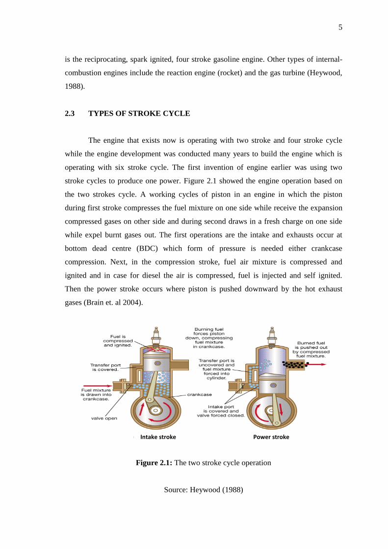
The engine that exists now is operating with two stroke and four stroke cycle
while the engine development was conducted many years to build the engine which is
operating with six stroke cycle. The first invention of engine earlier was using two
stroke cycles to produce one power. Figure 2.1 showed the engine operation based on
the two strokes cycle. A working cycles of piston in an engine in which the piston
during first stroke compresses the fuel mixture on one side while receive the expansion
compressed gases on other side and during second draws in a fresh charge on one side
while expel burnt gases out. The first operations are the intake and exhausts occur at
bottom dead centre (BDC) which form of pressure is needed either crankcase
compression. Next, in the compression stroke, fuel air mixture is compressed and
ignited and in case for diesel the air is compressed, fuel is injected and self ignited.
Then the power stroke occurs where piston is pushed downward by the hot exhaust
gases (Brain et. al 2004).
Figure 2.1: The two stroke cycle operation
Source: Heywood (1988)
Intake stroke Power stroke

6
The four strokes of a spark ignition (SI) engines operations was began with the
piston sucks up an air-fuel mixture by going back and then compresses it by going
fourth and fuel evaporates under the increase of temperature. When the piston comes
close to top dead centre (TDC), an ignition plug ignites the mixture by means of spark
which provokes sudden rise of temperature and pressure. The backward motion of the
piston permits the combustion gases to expand and the usable work is produced at this
moment. Finally, the forward movement of the piston expels the combustion gases.
Therefore, the four strokes cycle operation are the intake, compression, power and
exhaust as shown in Figure 2.2.
Figure 2.2: The four stroke cycle operation
Source: Heywood (1988)
The six stroke engine describes different approaches to the combustion engine,
since the 1990’s designed to improve their efficiency and reduce emissions. The engine
catches the most heat from the four stroke cycle and converts it to power an additional
power and exhaust stroke of the piston in the same cylinder. Design of such an engine
which is suitable either steam or air as working medium for the additional power stroke.
These six stroke engines have two power strokes, one because of the fuel and one by the
vapour of the air. Figure 2.3 showed the operations in six stroke engine, the first four
Spark plug ignite

7
lines, intake, compression, ignition and exhaust strokes occur in the normal four-stroke
engine. After the exhaust stroke, distilled water is injected into the combustion chamber.
The water expands to 1600 times in its own band and learns superheated vapour. The
sudden expansion of the volume generates a second power stroke, and this consists of
the fifth stroke. In the sixth stroke, the steam used is emitted. As the heat from the
cylinder is used, no additional cooling is required. The design also helps reduce fuel
consumption by 40%. The latest invention of six stroke engine designs in this class are
the Crower’s six stroke engine, invented by Bruce Crower of the USA, the Bajulaz
engine by the Bajulaz S A company of Switzerland, and the Velozeta six-stroke engine
by the Colege of Engineering at Trivandrum in India (Paswan, 2008).
Figure 2.3: The operation of six stroke cycle
Source: Paswan (2009)
Improving the efficiency of internal combustion engines is an ongoing area of
research where numerous design have been proposed based on traditional Otto or Diesel
cycles and all of these include four sequential thermodynamic process or strokes of the
piston. The performance of four stroke engine could be observed on Figure 2.4 that
illustrates a schematic of the typical four-stroke sequence for an Otto cycle and Figure
2.5 illustrates the corresponding pressure-volume trace.

8
Figure 2.4: Schematic of typical intake and exhaust valve events for a petrol engine
Otto cycle
Source: James C. Conklin (2010)
Figure 2.5: Schematic of pressure vs. volume for a typical petrol engine Otto cycle
Source: James C. Conklin (2010)
In six stroke engine, the cycle here proposed change additional two new strokes
that increase the work extracted per unit of fuel energy input. These additional strokes
include the capture and recompression of some of the exhaust stroke of the fourth,
followed by a water injection and the resulting expansion of the vapour or exhaust
mixture. The residual exhaust gas is trapped in the cylinder by closing the exhaust valve
earlier than usual before top centre (TC). The energy of the exhaust gases trapped
recompressed transferred to liquid water, causing it to evaporate and increase the
pressure. The increased pressure causes more work than other expansion process. The

9
mixture of steam exhaust gases are expelled atmospheric pressure near the point of
maximum expansion. The modified sequence of six strokes is illustrated in Figure 2.6
and the corresponding pressure-volume trace is shown in Figure 2.7.
Figure 2.6: Schematic of typical intake and exhaust valve events for the six stroke
engine cycle
Source: James C. Conklin (2010)
Figure 2.7: Schematic of pressure vs. volume for a six stroke engine cycle
Source: James C. Conklin (2010)
10
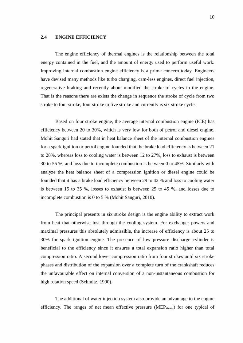
2.4 ENGINE EFFICIENCY
The engine efficiency of thermal engines is the relationship between the total
energy contained in the fuel, and the amount of energy used to perform useful work.
Improving internal combustion engine efficiency is a prime concern today. Engineers
have devised many methods like turbo charging, cam-less engines, direct fuel injection,
regenerative braking and recently about modified the stroke of cycles in the engine.
That is the reasons there are exists the change in sequence the stroke of cycle from two
stroke to four stroke, four stroke to five stroke and currently is six stroke cycle.
Based on four stroke engine, the average internal combustion engine (ICE) has
efficiency between 20 to 30%, which is very low for both of petrol and diesel engine.
Mohit Sanguri had stated that in heat balance sheet of the internal combustion engines
for a spark ignition or petrol engine founded that the brake load efficiency is between 21
to 28%, whereas loss to cooling water is between 12 to 27%, loss to exhaust is between
30 to 55 %, and loss due to incomplete combustion is between 0 to 45%. Similarly with
analyze the heat balance sheet of a compression ignition or diesel engine could be
founded that it has a brake load efficiency between 29 to 42 % and loss to cooling water
is between 15 to 35 %, losses to exhaust is between 25 to 45 %, and losses due to
incomplete combustion is 0 to 5 % (Mohit Sanguri, 2010).
The principal presents in six stroke design is the engine ability to extract work
from heat that otherwise lost through the cooling system. For exchanger powers and
maximal pressures this absolutely admissible, the increase of efficiency is about 25 to
30% for spark ignition engine. The presence of low pressure discharge cylinder is
beneficial to the efficiency since it ensures a total expansion ratio higher than total
compression ratio. A second lower compression ratio from four strokes until six stroke
phases and distribution of the expansion over a complete turn of the crankshaft reduces
the unfavourable effect on internal conversion of a non-instantaneous combustion for
high rotation speed (Schmitz, 1990).
The additional of water injection system also provide an advantage to the engine
efficiency. The ranges of net mean effective pressure (MEPsteam) for one typical of
11
steam combustion engine produce about 0.75 to 2.5 bar meanwhile the mean effective
pressure of naturally petrol engines are up to 10 bar. Thus, this concept has the potential
to show a very significant increase in engine efficiency and fuel economy (James C.
Conklin, 2009).
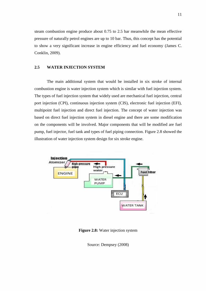
2.5 WATER INJECTION SYSTEM
The main additional system that would be installed in six stroke of internal
combustion engine is water injection system which is similar with fuel injection system.
The types of fuel injection system that widely used are mechanical fuel injection, central
port injection (CPI), continuous injection system (CIS), electronic fuel injection (EFI),
multipoint fuel injection and direct fuel injection. The concept of water injection was
based on direct fuel injection system in diesel engine and there are some modification
on the components will be involved. Major components that will be modified are fuel
pump, fuel injector, fuel tank and types of fuel piping connection. Figure 2.8 showed the
illustration of water injection system design for six stroke engine.
Figure 2.8: Water injection system
Source: Dempsey (2008)

12
The most important criteria in this system are the water injection timing and the
duration of injection, the water distribution in the combustion chamber, the moment in
time when combustion starts, the amount of particle of water metered to the engine per
degree crankshaft and the total injected water quantity in accordance with engine
loading during fifth stroke.
2.5.1 Water Tank
This is the obvious place to start in any full system explanation. The latest fuel
tank model was different with the tanks on early carburettor equipped vehicles which it
is a sealed unit that allows the natural gas of the fuel to delivery to the pump by slightly
pressurizing the system as shown in Figure 2.9. Present fuel tanks for internal
combustion engines are rigid containers made of metal or plastic. These fuel tanks are
vented to atmosphere or in some cases are pressurized so that a vacuum is not built up
in the tank as fuel is used by the engine (Chris Shou, 1969). The fuel tank can be
replaced as water tank to keep the amount of water before it is delivered to the water
pump.
Figure 2.9: Example of water tank
Source: Chris Shou (1969)

13
2.5.2 Types of Injection Pump
The main component in fuel injection system recently is injection pump and its
function as the device that delivery fuel from fuel tank into the cylinder of petrol engine
or diesel engine. The history invented the injection pump by Robert Bosh in early 1927
that used in car diesel at that time. Generally, most of the injection pump in an engine
only can deliver the fuel (petrol or diesel). However, there is the injection pump that
available to deliver any liquid such as water that will be applied in six stroke engine.
Some of fuel pumps are suitable as well as to deliver the water around of
injection system. Two types of fuel pumps are used in modern automobile are
mechanical and electrical pumps. Mechanical fuel pumps are diaphragm pumps
mounted on the engine and operated by an eccentric cam usually on the camshaft as
shown in Figure 2.10. A rocker arm attached to the eccentric moves up and down
flexing the diaphragm and pumping the fuel to the engine. Most of carburetted
automobile engines used mechanical fuel pump to transfer fuel into fuel bowls of the
carburettor. The mechanical pumps operate on pressures of 4-6 psi (pounds per square
inch). Thus, this pump are not suitable to deliver the water because the low pressure.
(Bordoff et al,. 1995)
Figure 2.10: Configuration components in type of mechanical fuel pump
Source: Bordoff (1995)