water management barnett shale - tacwa · water management. barnett shale. november 21, ......
TRANSCRIPT
Water ManagementBarnett ShaleNovember 21, 2008
2
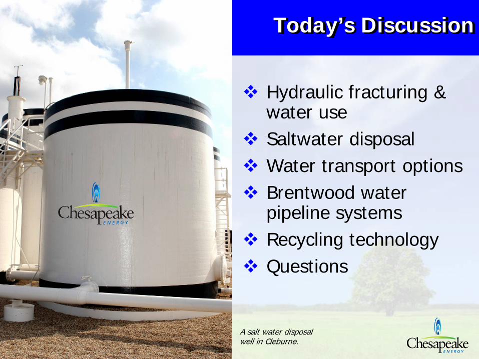
Today’s Discussion
Hydraulic fracturing & water useSaltwater disposalWater transport optionsBrentwood water pipeline systemsRecycling technologyQuestions
A salt water disposal well in Cleburne.
3
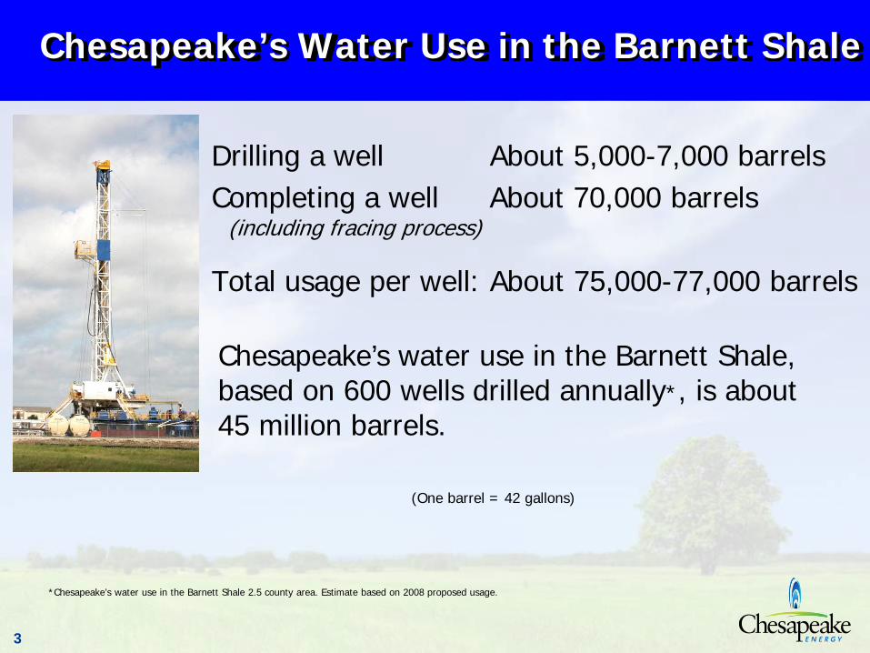
Chesapeake’s Water Use in the Barnett Shale
Drilling a well About 5,000-7,000 barrelsCompleting a well About 70,000 barrels
(including fracing process)
Total usage per well: About 75,000-77,000 barrels
Chesapeake’s water use in the Barnett Shale, based on 600 wells drilled annually*, is about 45 million barrels.
*Chesapeake’s water use in the Barnett Shale 2.5 county area. Estimate based on 2008 proposed usage.
(One barrel = 42 gallons)
4
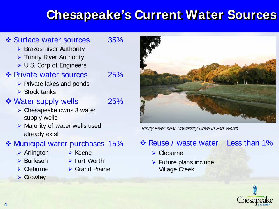
Chesapeake’s Current Water Sources
Surface water sources 35%Brazos River AuthorityTrinity River AuthorityU.S. Corp of Engineers
Private water sources 25%Private lakes and ponds Stock tanks
Water supply wells 25%Chesapeake owns 3 water supply wellsMajority of water wells usedalready exist
Municipal water purchases 15%ArlingtonBurlesonCleburneCrowley
Trinity River near University Drive in Fort Worth
Reuse / waste water Less than 1%CleburneFuture plans includeVillage Creek
KeeneFort WorthGrand Prairie
5
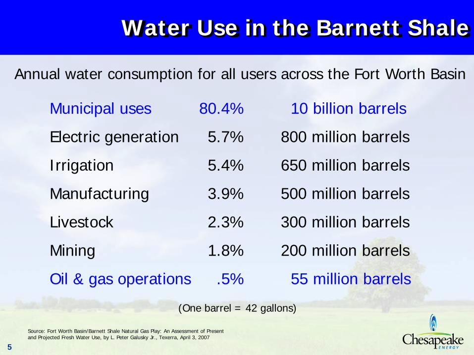
Water Use in the Barnett Shale
Municipal uses 80.4% 10 billion barrels
Electric generation 5.7% 800 million barrels
Irrigation 5.4% 650 million barrels
Manufacturing 3.9% 500 million barrels
Livestock 2.3% 300 million barrels
Mining 1.8% 200 million barrels
Oil & gas operations .5% 55 million barrels
Source: Fort Worth Basin/Barnett Shale Natural Gas Play: An Assessment of Present and Projected Fresh Water Use, by L. Peter Galusky Jr., Texerra, April 3, 2007
(One barrel = 42 gallons)
Annual water consumption for all users across the Fort Worth Basin
6
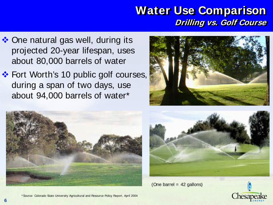
Water Use ComparisonDrilling vs. Golf Course
*Source: Colorado State University Agricultural and Resource Policy Report, April 2004
One natural gas well, during its projected 20-year lifespan, uses about 80,000 barrels of waterFort Worth’s 10 public golf courses, during a span of two days, use about 94,000 barrels of water*
(One barrel = 42 gallons)
7
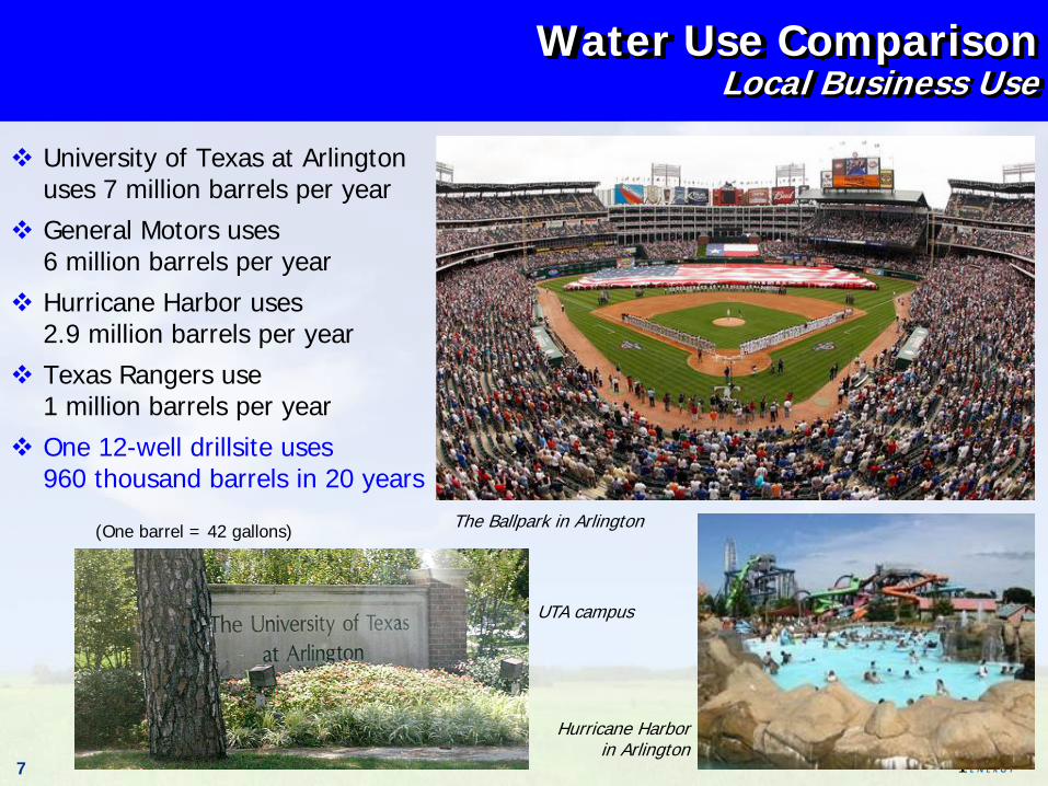
Water Use ComparisonLocal Business Use
University of Texas at Arlington uses 7 million barrels per yearGeneral Motors uses 6 million barrels per yearHurricane Harbor uses2.9 million barrels per yearTexas Rangers use1 million barrels per yearOne 12-well drillsite uses960 thousand barrels in 20 years
The Ballpark in Arlington
Hurricane Harbor in Arlington
UTA campus
(One barrel = 42 gallons)
8
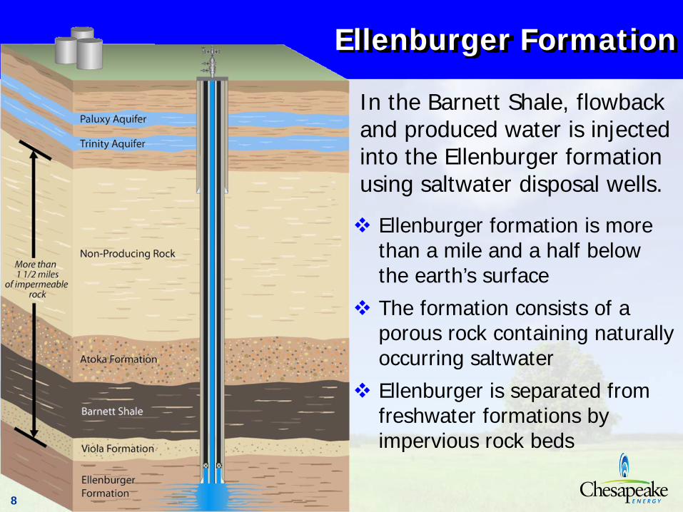
Ellenburger Formation
Ellenburger formation is more than a mile and a half below the earth’s surfaceThe formation consists of a porous rock containing naturally occurring saltwaterEllenburger is separated from freshwater formations by impervious rock beds
In the Barnett Shale, flowback and produced water is injected into the Ellenburger formation using saltwater disposal wells.
9
Injection Wells
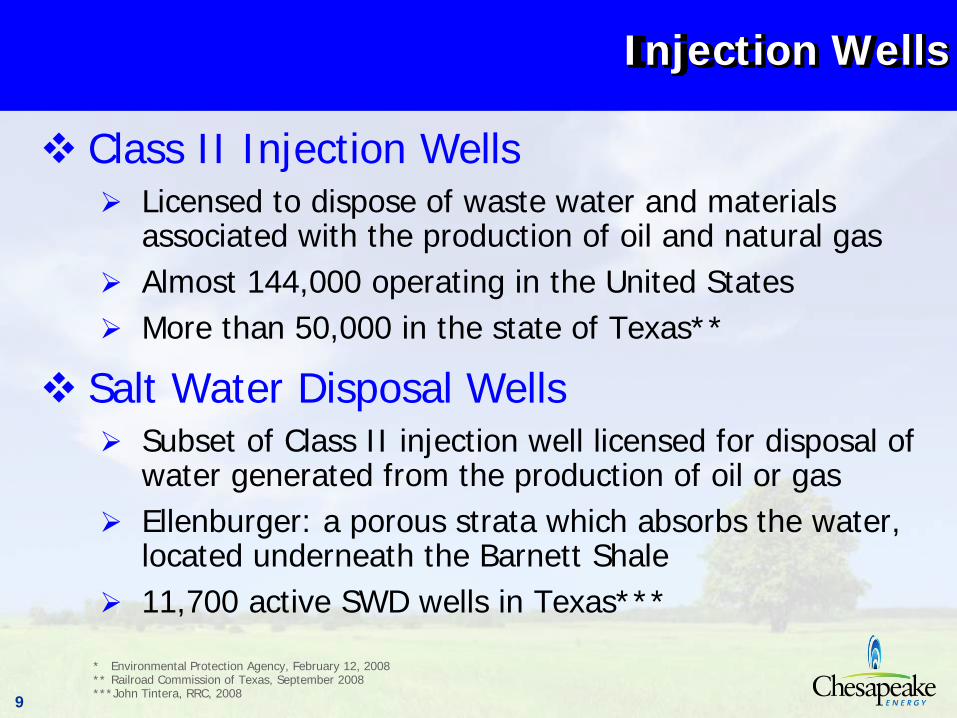
Class II Injection WellsLicensed to dispose of waste water and materials associated with the production of oil and natural gas Almost 144,000 operating in the United StatesMore than 50,000 in the state of Texas**
Salt Water Disposal WellsSubset of Class II injection well licensed for disposal of water generated from the production of oil or gasEllenburger: a porous strata which absorbs the water, located underneath the Barnett Shale11,700 active SWD wells in Texas***
* Environmental Protection Agency, February 12, 2008** Railroad Commission of Texas, September 2008***John Tintera, RRC, 2008
10
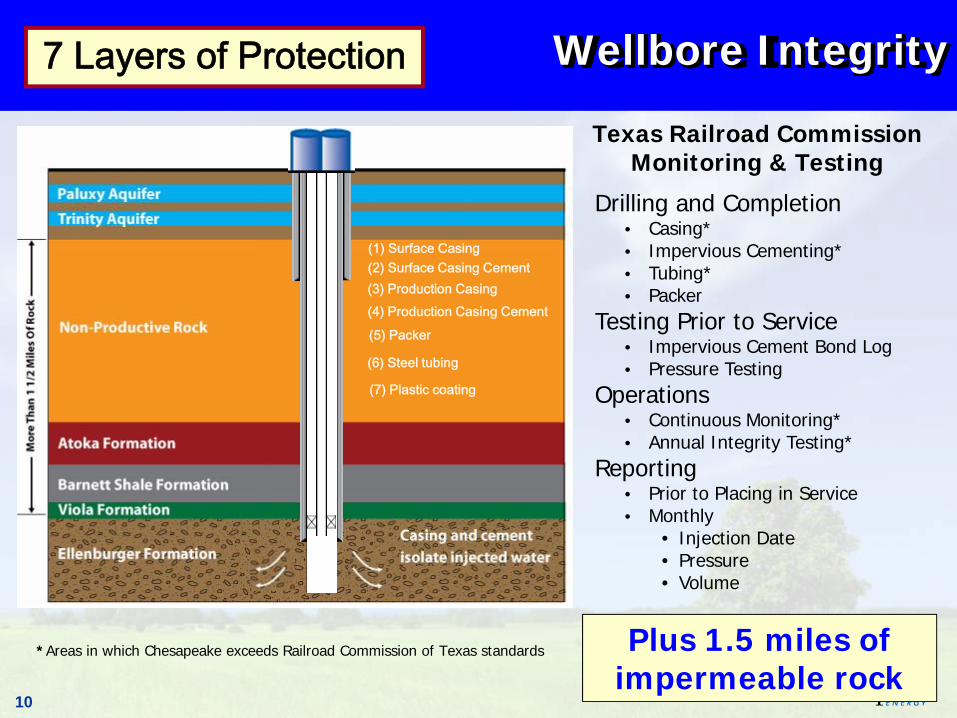
Wellbore Integrity
Texas Railroad CommissionMonitoring & Testing
*Areas in which Chesapeake exceeds Railroad Commission of Texas standards
(5) Packer
(1) Surface Casing
(6) Steel tubing
(2) Surface Casing Cement(3) Production Casing(4) Production Casing Cement
7 Layers of Protection
(7) Plastic coating
Plus 1.5 miles of impermeable rock
Drilling and Completion• Casing*• Impervious Cementing*• Tubing*• Packer
Testing Prior to Service• Impervious Cement Bond Log• Pressure Testing
Operations• Continuous Monitoring*• Annual Integrity Testing*
Reporting• Prior to Placing in Service• Monthly
• Injection Date• Pressure• Volume
11
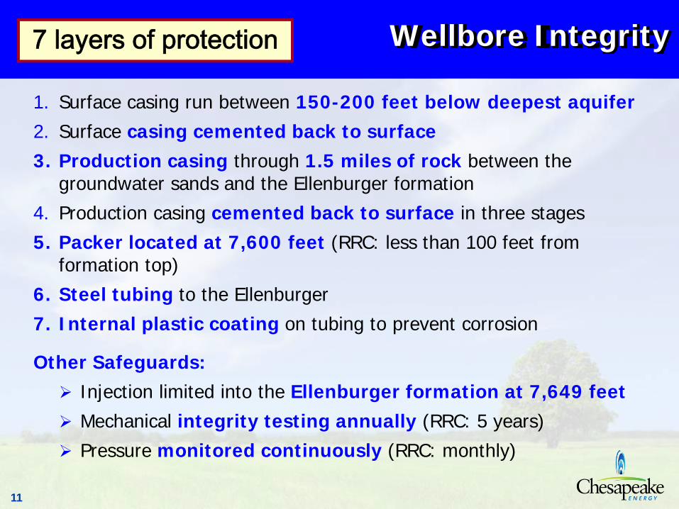
Wellbore Integrity
1. Surface casing run between 150-200 feet below deepest aquifer2. Surface casing cemented back to surface3. Production casing through 1.5 miles of rock between the
groundwater sands and the Ellenburger formation4. Production casing cemented back to surface in three stages 5. Packer located at 7,600 feet (RRC: less than 100 feet from
formation top)6. Steel tubing to the Ellenburger7. Internal plastic coating on tubing to prevent corrosion
Other Safeguards:Injection limited into the Ellenburger formation at 7,649 feetMechanical integrity testing annually (RRC: 5 years)Pressure monitored continuously (RRC: monthly)
7 layers of protection
12
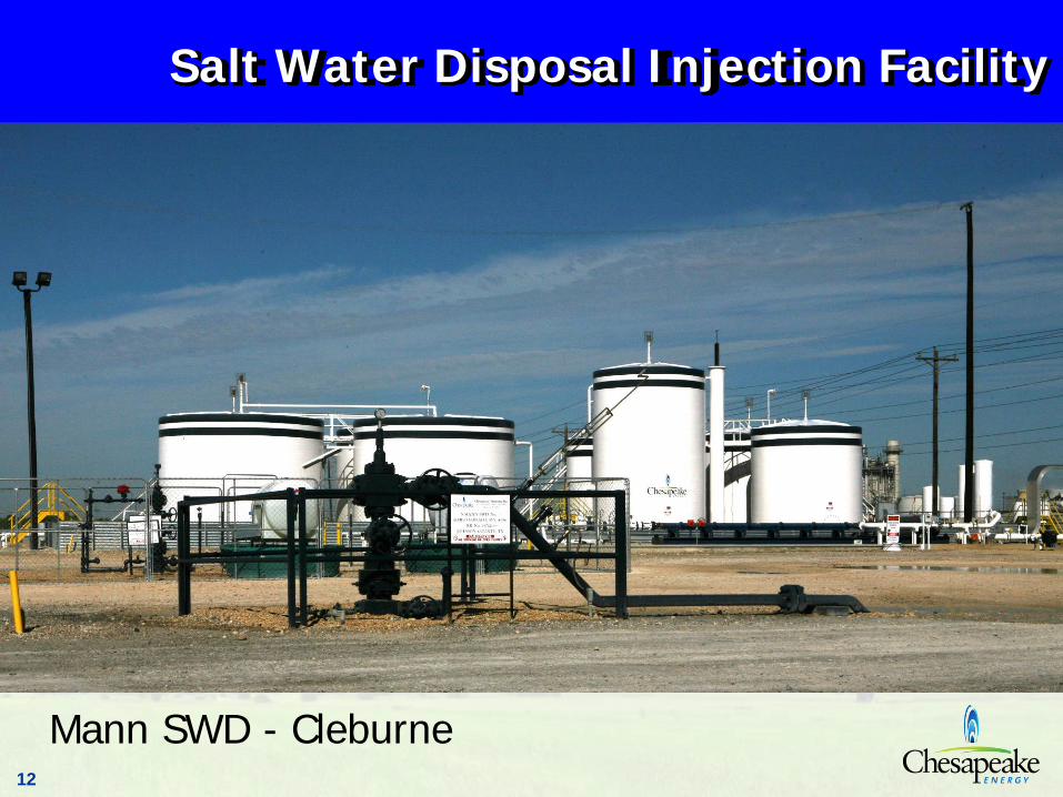
Salt Water Disposal Injection Facility
Mann SWD - Cleburne
13
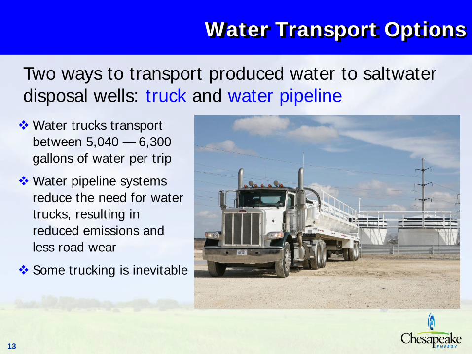
Water trucks transport between 5,040 — 6,300 gallons of water per trip
Water pipeline systems reduce the need for water trucks, resulting in reduced emissions and less road wear
Some trucking is inevitable
Water Transport Options
Two ways to transport produced water to saltwater disposal wells: truck and water pipeline
14
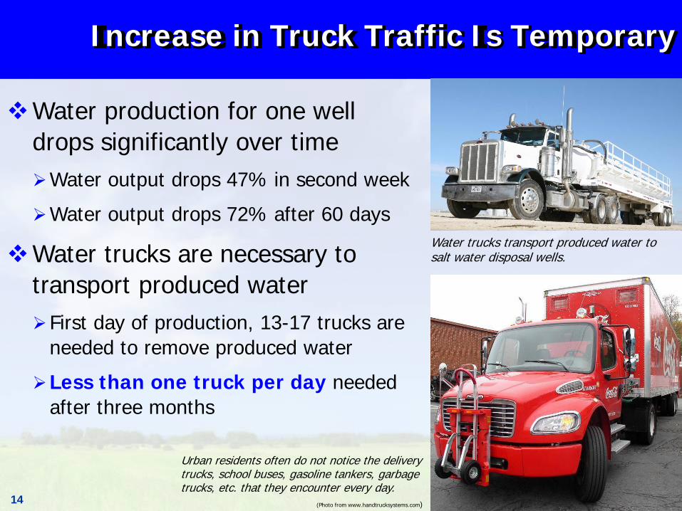
Increase in Truck Traffic Is Temporary
Water production for one well drops significantly over time
Water output drops 47% in second week
Water output drops 72% after 60 days
Water trucks are necessary to transport produced water
First day of production, 13-17 trucks are needed to remove produced water
Less than one truck per day needed after three months
Water trucks transport produced water to salt water disposal wells.
Urban residents often do not notice the delivery trucks, school buses, gasoline tankers, garbage trucks, etc. that they encounter every day.
(Photo from www.handtrucksystems.com)
15
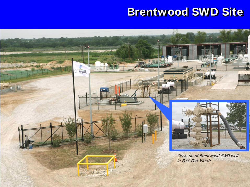
Brentwood SWD Site
Close-up of Brentwood SWD well in East Fort Worth.
16
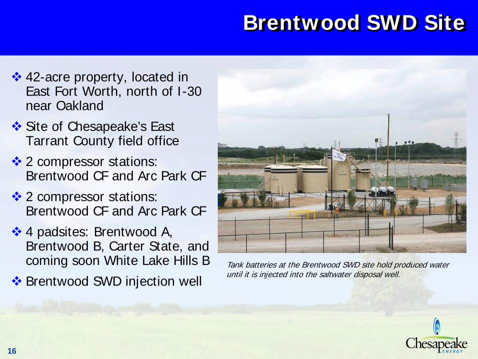
Brentwood SWD Site
42-acre property, located in East Fort Worth, north of I-30 near OaklandSite of Chesapeake’s East Tarrant County field office2 compressor stations: Brentwood CF and Arc Park CF2 compressor stations: Brentwood CF and Arc Park CF4 padsites: Brentwood A, Brentwood B, Carter State, and coming soon White Lake Hills BBrentwood SWD injection well
Tank batteries at the Brentwood SWD site hold produced water until it is injected into the saltwater disposal well.

17
Reducing Traffic at Brentwood
Long driveway improves accessibility for water trucks entering the Brentwood site, helping to minimize traffic on adjoining road
Planned water pipeline system connecting drillsites to the Brentwood SWD will reduce the number of trucks needed to transport produced water
18
Strategically Located SWD Wells & Pipelines
Success of the DFW Airport and Brentwood SWDs can be replicated all over the Barnett Shale region Strategically located SWD wells can reduce miles trucks must travel to dispose of produced waterAddition of water pipeline systems can lessen truck traffic even more dramaticallyResult is decrease in water truck traffic, related emissions and road wear
19
What About Recycling?
Majority of the water returned from a well (95%), with its high salt content, is too saturated to make its recycling economically viable
Natural gas industry is testing the feasibility of recycling flowback water with limited success
Flowback water accounts for only about 5% of water byproduct
About a week after fracing, flowback salt content can reach as high as 70,000 ppm, more than twice the salinity of sea water
Current recycling technologies require increased space in which to operate, translating into larger footprint on the environment
Increased recycling efforts mean increased truck traffic, to move the recycled water back out into the field so that it can be used again
20
Evaluating Recycling Technologies
Chesapeake Energy and others in the industry are constantly evaluating opportunities to treat the water generated from natural gas production, so that less of it will need to be injected using SWD wells
Barnett Shale Water Conservation Management Committee meets regularly to evaluate feasible recycling optionsPilot recycling projects are being undertaken by natural gas companies in an effort to increase efficiency and feasibility of current recycling technologiesChesapeake has begun a pilot program involving water evaporation system technology
21
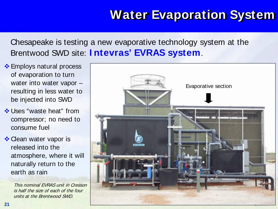
Chesapeake is testing a new evaporative technology system at the Brentwood SWD site: Intevras’ EVRAS system.
Water Evaporation System
Employs natural process of evaporation to turn water into water vapor –resulting in less water to be injected into SWD
Uses “waste heat” from compressor; no need to consume fuel
Clean water vapor is released into the atmosphere, where it will naturally return to the earth as rain
This nominal EVRAS unit in Cresson is half the size of each of the four units at the Brentwood SWD.
Evaporative section
22
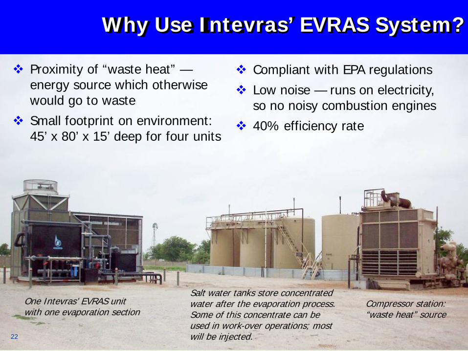
Why Use Intevras’ EVRAS System?
Proximity of “waste heat” —energy source which otherwise would go to wasteSmall footprint on environment: 45’ x 80’ x 15’ deep for four units
Compliant with EPA regulationsLow noise — runs on electricity, so no noisy combustion engines40% efficiency rate
Salt water tanks store concentrated water after the evaporation process. Some of this concentrate can be used in work-over operations; most will be injected.
Compressor station: “waste heat” source
One Intevras’ EVRAS unit with one evaporation section
22
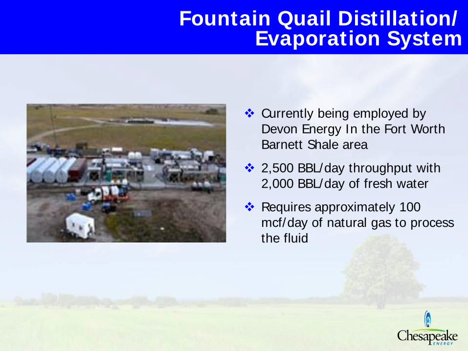
Currently being employed by Devon Energy In the Fort Worth Barnett Shale area
2,500 BBL/day throughput with 2,000 BBL/day of fresh water
Requires approximately 100 mcf/day of natural gas to process the fluid
Fountain Quail Distillation/Evaporation System
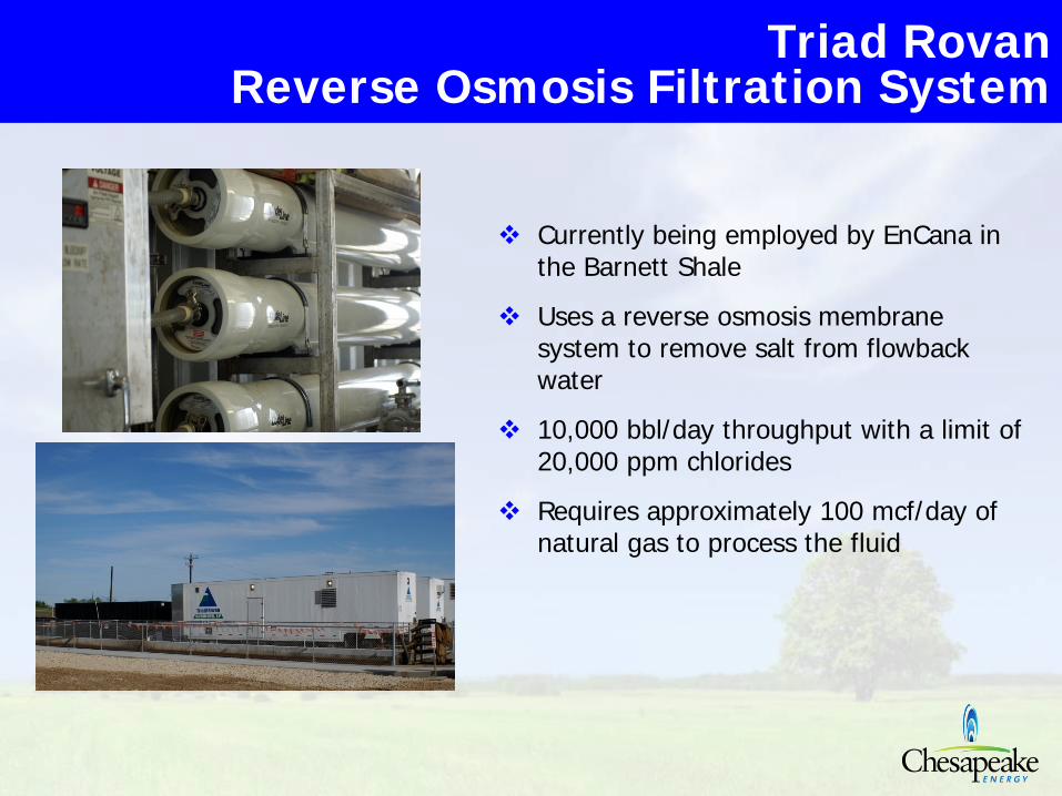
Currently being employed by EnCana in the Barnett Shale
Uses a reverse osmosis membrane system to remove salt from flowbackwater
10,000 bbl/day throughput with a limit of 20,000 ppm chlorides
Requires approximately 100 mcf/day of natural gas to process the fluid
Triad RovanReverse Osmosis Filtration System
25
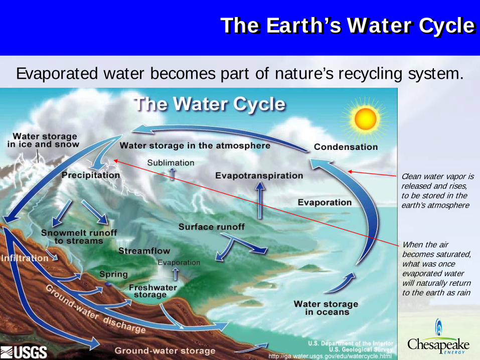
The Earth’s Water Cycle
Evaporated water becomes part of nature’s recycling system.
Clean water vapor is released and rises, to be stored in the earth’s atmosphere
When the air becomes saturated, what was once evaporated water will naturally return to the earth as rain
26
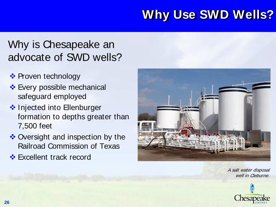
Why Use SWD Wells?
Proven technologyEvery possible mechanical safeguard employedInjected into Ellenburger formation to depths greater than 7,500 feetOversight and inspection by the Railroad Commission of TexasExcellent track record
Why is Chesapeake an advocate of SWD wells?
A salt water disposal well in Cleburne.
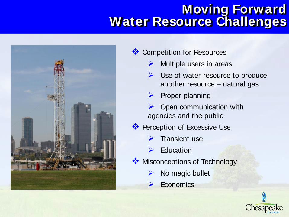
Moving ForwardWater Resource Challenges
Competition for Resources
Multiple users in areas
Use of water resource to produce another resource – natural gas
Proper planning
Open communication with agencies and the public
Perception of Excessive Use
Transient use
Education
Misconceptions of Technology
No magic bullet
Economics
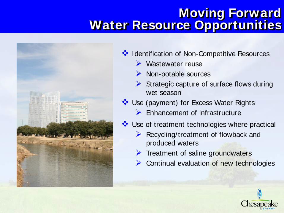
Moving ForwardWater Resource Opportunities
Identification of Non-Competitive ResourcesWastewater reuseNon-potable sourcesStrategic capture of surface flows during wet season
Use (payment) for Excess Water RightsEnhancement of infrastructure
Use of treatment technologies where practicalRecycling/treatment of flowback and produced watersTreatment of saline groundwatersContinual evaluation of new technologies

29
Chesapeake Energy Corporation | Barnett Shale Headquarters
100 Energy Way, Fort Worth, Texas 76102
817.502.5000 | chk.com
www.AskChesapeake.com
NYSE: chk