water supply well guidelines - seidc.com€¦ · water supply well guidelines for use in developing...
TRANSCRIPT

WATER SUPPLY WELL
GUIDELINES
for use in
DEVELOPING COUNTRIES
THIRD EDITION

ii
"More people die from unsafe wa-
ter than from all forms of violence,
including war."
– UN Secretary-General Ban Ki-moon
—————
“Drinking water supply well
drilling & pump installer
services, when properly
performed, do more to
extend the average life
expectancy and improve the
quality of life in develop-
ing countries than all the
medical doctors.”
- Anonymous

iii
WATER SUPPLY WELL
GUIDELINES
for use in
DEVELOPING COUNTRIES
Third Edition August 2014
Reprinted November 2014
Principal Author & Editor:
Stephen J. Schneider, BSME, MGWC
Copyright © 2014 by Stephen J. Schneider
All rights reserved. No part of this book may be used or reproduced, stored in retrieval system or transmitted in any form or by any means, electronic, mechanical, photocopying, recording, or otherwise, without
the written permission of Stephen J. Schneider.
ISBN 978-0-9884685-3-5

iv
ACKNOWLEDGEMENTS The following provided comment or support facilitating the development of
these guidelines:
Organizations—
Allegra Print & Imaging
American Water Resources Association
Gregg Drilling & Testing, Inc.—John Gregg, President, BSGE
Loughborough University WEDC
Moody’s of Dayton, Inc.
National Ground Water Association
National Ground Water Research & Educational Foundation
Rural Water Supply Network
Schneider Equipment, Inc. / Schneider Water Services
University of Oklahoma WaTER Center
Individuals—
Keg Alexander Lynn Bartholomew
Art Becker, CPG, MGWC Jessica Bentz
Michael E Campana, Ph.D Lawrence Cerrillo, CPG
Kamran N. Choudhri Dr. Kerstin Danert
Luis Antonio Domínguez Jr. Kyle Doran
Stephen Douglas Lloyd Duplantis
Martha Espinoza Rodrigo Estrada
Emmanuel Evans Scott Fowler, CWD/PI
Trisha Freeman Jaime Gallardo
Kevin Gill Matt Hangen
John W. Henrich, MGWC Kyle Hoover
Raul Ibarra David K. Kreamer, Ph.D
Michael Langer Osear Larrea
Dany Lopez W. Richard, Laton, Ph.D, PG, CHG, CPG
Michael Maldonado Larry Martin, Hydrogeologist
Darwin Martinez Sandy Masters
Kevin McCray, CAE Christopher McKeand
Daniel T. Meyer, MGWC Jennifer Michel
Evan Miles Alex Mora
Jon Naugle Bwire S. Ojiambo, Ph.D
Sunny Pannu Michael Paulson
Rachel Paulson John Pitz

v
Gonzalo Pulido Ron Reed
Gabriel Sabogal David A. Sabatini, Ph.D, PE
Manuel Salamanca Jennifer Schneider
Karen T. Schneider, RN, MSN Kriss D. Schneider
Miriam E. Schneider, RN, MSN Ronnie K. Schneider, MS, ME
Robert Schultz Dr. Stephen E. Silliman
Floyd Sippel Stuart Smith, CGWP
Daniel Stephens Ralph Taylor Jr., CWD
Keith Thompson Therese Ure
Vincent Uhl, CPG, CPH Albino Vasquez
Ingrid Verstraeten Eduardo Villarreal
Mary Waldo, Ph.D Jaynie Whinnery, BSME
Tami Woolfe Lei Yang, Ph.D, PE
Photos / images:
National Ground Water Research & Education Foundation
Robert Wright, Orthodox Presbyterian Uganda Mission
Pedro J. de Velasco R. S.J.
Luis Antonio Domínguez Hernández
W. Richard Laton, PhD, PG, CHG, CPG
Google Images
Stephen J. Schneider, BSME, MGWC
United States Geological Society
Drafts of the guidelines were circulated to thousands in addition to being pre-
sented for discussion or utilized at many conferences (see Preface). The prin-
cipal author acknowledges that there were others providing input and com-
ment; however, names were not documented at all events. He sincerely apol-
ogizes to any person or group that he inadvertently failed to recognize, or
incorrectly recognized.
Special Acknowledgements –
My wife Miriam — Her enthusiastic support, input and conviction assured
completion of the first and subsequent editions of these guidelines.
Luis G. Verplancken, S.J. (deceased), those continuing to support his vision
and the Tarahumara people they served and serve — They continue
to inspire me.
Stephen J. Schneider, Principal Author & Editor [email protected]

vi
PREFACE
Presentations by individuals working in developing countries prompted further discussion at the 2008 National Ground Water Association (NGWA) Expo about the need for standards. That discussion resulted in the creation of draft guidelines (originally referred to as standards) related to water supply wells and their well head appurtenances for use in developing countries.
The initial draft was first presented for comment at the June 2009 Groundwater for the Americas conference in Panama City, Panama where the concept and draft document attracted significant attention.
Subsequent drafts were presented for review and comment at the: October 2009 International WaTER Conference, University of
Oklahoma, Norman, OK December 2009 NGWA Expo in New Orleans, LA November 2010 American Water Resources Association (AWRA)
Annual Conference in Philadelphia, PA. Considerable national and international input resulted from these conferences and via e-mail list circulations, web postings and other discussion/reviews. The document came to fruition and the first edition was published in October 2011 and initially presented at the 2011 International WaTER Conference in Norman, OK.
The first edition was enthusiastically received. Many constructive comments were subsequently provided resulting in the second edition (2012). Further comments and insight, especially from the 36th WEDC International Conference in Nakuru, Kenya in 2013, prompted this third edition. It is hoped and expected that comments and suggestions will continue to be provided, which will result in further refinements.
These well guidelines are intended to support those working with groundwater systems in developing countries. The document is a teaching, reference and administrative tool, designed especially for those intimately involved in improving the quality and quantity of water in developing countries.
Endorsements by government and non-government organizations (NGOs), especially those involved in improving the quality and quantity of drinking water in developing countries, are encouraged.

vii
TABLE OF CONTENTS
1 Purpose & Use………………………………………………………….. 1
2 Groundwater Availability……………………………………...….. 4
3 Cost Benefit………………………………………………………………. 5
4 Definitions………………………………………………………………… 6
5 Well Location……………………………………………………………. 9
6 Drilling Methods……………………………………………………….. 11
7 Drilling Products……………………………………………………….. 12
8 Well Annular Surface Seal…………………………………………. 13
9 Commingling and Leakage……………...………………………… 27
10 Casing and Liner………………………………………………………... 27
11 Other Well Materials……………………………………………….. 33
12 Plumbness and Alignment………………………………………… 33
13 Well Development……………………………………………………. 34
14 Surface Completion…………………………………………………... 34
15 Disinfection………………………………………………………………..35
16 Testing………………………………………………………………………. 37
17 Well Decommissioning……………………………………………... 40
18 Documentation…………………………………………………………. 42
19 Personnel Safety……………………………………………………….. 47
Appendix I— Filter Pack design……………………………………….. 48
Appendix II— Well Design Pros and Cons ……………………... 52
References and Resources………………………………………………. 54
About the Principal Author & Editor……………………………….. 55

1
1 PURPOSE & USE
These guidelines are considered minimum requirements for basic
protection of the groundwater resource and for the health and
safety of those that develop and use the resource. These
guidelines are intended to address basic water supply well
construction, pumping equipment, and maintenance issues. Water
supply wells include wells designed for domestic, municipal,
community, industrial, commercial, irrigation and/or livestock
water supply use in addition to aquifer storage (injection) and
recovery wells.
These guidelines are encouraged to be used as an education and
training tool as well as an everyday field guide for those performing
the work. These guidelines may also be used as a basis in
establishing national, regional or local standards in regions where
there are no standards or very limited standards. Reference No. 4,
page 54, is an example of a well standard. These guidelines may
also be useful for establishing specifications in procurement or
construction documents and hydrophilanthropic agreements.
This document is not intended to include or limit the countless
means, methods and designs for the work except in unique
situations where appropriate. It is up to those responsible for the
construction to determine the appropriate means, methods and
design. Regardless, hand dug or excavated wells are not
encouraged by these guidelines given that there is not a strong
consensus as to the appropriateness of this type of well
construction. Hand dug or excavated wells pose significant concern
for the safety of those constructing, maintaining and using such
wells. In addition, the difficulty of constructing and maintaining a
sanitary supply that is free of harmful pathogens using the dug well
technique argue against the practice except where there is no

2
reasonable alternative. In those situations, it should be considered
a preliminary or temporary practice unless such wells are
constructed in conformance to this document.
Water well construction is not for amateurs. It is always
recommended that whenever possible, appropriately skilled and
reputable local individuals, companies or agencies be encouraged
to perform the work addressed herein. However, when those
individuals or entities are not available, these guidelines can be
used to assist in the training of local citizens toward becoming
skilled service providers. They should also be made available to
those using the groundwater supply systems as a guide to facilitate
in the long-term, safe, sanitary use and protection of the
groundwater resource.
If there are standards, rules or laws in effect and applicable by
other authorities, the more restrictive criteria for each requirement
should be followed. These guidelines are not intended to replace
any local, municipal, provincial, national or other laws or standards;
these guidelines are meant to supplement such laws or standards,
or in the absence thereof, to be considered the minimum standard.
Respect should be afforded all licensing, permitting, construction,
and other applicable laws in each area of each country.
These guidelines are written utilizing wording that suggests more of
a recommendation than a mandate. For example, you will notice
the use of the word “should” for most requirements. This is done
because, in many rural undeveloped areas, the availability of
materials specified herein or the cost of compliance may be
inappropriate when considering the lives at stake. If it is desired to
use these guidelines as a mandatory requirement, substitute the
word “shall” or “must” for “should”. Refer to the definitions in
section 4, pages 7 and 8. For a publication using the mandatory
language, contact the principal author.

3
FIGURE 1

4
2 GROUNDWATER AVAILABILITY
Water is in perennial motion as exhibited by the Hydrologic Cycle
(Figure 1). Our planet has the same amount of water today as we
did yesterday and will have tomorrow. Water is being naturally
recycled by nature even with man’s constant diversion, use and
quality alterations. The earth often acts as a natural filter for much
of the earth’s fresh water, especially in filtering out most harmful
pathogens.
Most of the liquid water on earth is saline; less than 1% of all water
on the planet is considered fresh water (Figure 2). However, of all
the fresh water on earth, it may be surprising to find that there is
over 100 times more fresh groundwater than there is fresh surface
water. With the depletion of available supplies of surface water,
which often contains harmful pathogens or chemicals, groundwater
holds the promise as the source for much our future safe drinking
water supplies. FIGURE 2

5
3 COST BENEFIT
J. Whinnery in 2012 (Reference No. 6, page 54) developed a Cost-
Benefit Analysis (CBA) that compared the costs and benefits of
properly completed wells versus inferior completed wells. The CBA
revealed the following:
Almost 40 times more benefit, than cost, is provided with a
properly constructed, operated and maintained well system.
There is approximately 5 times more net value realized solely
as a result of the implementation of an operation and
maintenance (O&M) program.
Wells providing localized poor water quality should not be
considered acceptable.
Construction of such a well results in a negative net present
value; that is, there is more cost than benefit (a benefit-cost
ratio less than 1).
A properly constructed well will have at least 3 times more net
value than an inferior well.
The multiplier approaches infinity if water quality has also
been compromised in the inferior well.
Inferior construction that results in groundwater contamination
or aquifer damage should not be considered acceptable.
Although it is not specifically analyzed in the CBA, it can be
inferred that well construction which compromises aquifer
quality or results in loss of aquifer head (e.g. commingling of
aquifers or uncontrolled artesian pressure), will have negative
impacts in the form of reduced large-scale benefits in addition
to added costs of remediation or mitigation. These negative
impacts will most certainly result in a negative net present
value.

6
4 DEFINITIONS
Aquifer — A geologic formation, group of formations, or part of a
formation that contains saturated and permeable material capable
of transmitting water in sufficient quantity to supply wells or springs
and that contains water that is similar throughout in characteristics
such as potentiometric surface head, chemistry, and temperature.
Annulus — The space between the outside diameter of a casing or
liner and the borehole wall or the inside diameter of another casing
or liner. It is synonymous with annular space.
Artesian aquifer — A confined aquifer in which groundwater rises
above the level at which it was first encountered, whether or not
the water flows at land surface.
Backfill — Inorganic material placed or left in a part of the well or
its annulus that is not sealant, filter pack or formation stabilizer. It
may be used to provide temporary or permanent support for a well
intake assembly, for a liner or casing, for filter pack or formation
stabilizer, or for sealant. Backfill may also be used as a barrier to
prevent undesirable migration of a fluid sealant prior to it taking
solid form.
Casing — The pipe that is a permanent part of the well, which
extends above the ground surface, and around which an annular
seal is placed. Casing in a well may be of multiple diameters and
connected at size changes by welding, threading, grouting or with a
minimum 2 meter [6 feet] overlap if the overlap is above the static
water level.
Commingling — Flow or leakage of groundwater within a well (e.g.
within the casing, liner, screen, borehole and/or annulus) from one
aquifer to another aquifer, resulting from gravity flow or artesian
pressure.

7
Consolidated formation — Materials that have become firm and
coherent through natural rock-forming processes. These include,
but are not limited to, basalt, sandstone, claystone, shale,
limestone, dolomite and granite.
Drill fluid — Water, air, or mud (with or without additives) used
down the borehole during well construction. Drill fluid functions
may include: hole stabilization, carrying or temporarily supporting
cuttings, cooling of the drill bit.
Filter pack — Sand, gravel or a manufactured material (e.g. glass
beads) placed in the annulus of the well between the borehole wall
and the well intake assembly to control formation material from
entering the well through the well intake. Filter pack should be
clean, well rounded, uniform siliceous material. See Appendix I.
Formation stabilizer — Sand or gravel placed in the annulus of the
well between the borehole wall and the well intake to provide
temporary or long-term support for the borehole. Formation
stabilizer is not designed to control formation material from
entering the well through the well intake.
Gravel pack — A term that is becoming less commonly used. It is
sometimes used synonymously with filter pack or considered a type
of filter pack. It also has been used to describe gravel used as
formation stabilizer and/or backfill.
Head — The elevation to which water rises to as a result of
pressure. Head is usually expressed in meters [feet].
Liner — Pipe in the well that is not part of a pump but is used to
line the borehole wall to prevent collapse. An annular seal is never
placed around a liner.
May — Means the statement in which it is used expresses a
specification that is suggestive, optional and is not mandatory.
Must — Means the statement in which it is used expresses a
mandatory requirement or obligation that allows no exceptions.

8
Permeability — The ability of a formation to transmit water.
Potable water — Water that is safe enough to be consumed by
humans with low risk of immediate or long term harm.
Potentiometric surface — An imaginary surface representing the
level to which water will rise in a well as a result of pressure under
which it is confined in an aquifer.
Shall — Means the statement in which it is used expresses a
mandatory requirement or obligation that allows no exceptions.
Should — Means the statement expresses a requirement or an
obligation that allows an exception only if extreme conditions
warrant otherwise.
Unconsolidated formation — Sediment that is naturally occurring,
loosely cemented, or poorly indurated including clay, sand, silt and
gravel.
Static Water Level (SWL) —The level of water in a well that is not
being affected by withdrawal of groundwater. Affects of
withdrawal include withdrawal from other wells, flowing artesian,
and recovery after withdrawal has stopped. SWL is usually
expressed in meters [feet] below a specified point such as top of
casing or ground surface. For flowing artesian wells, it may be
expressed as pressure (kPa [psi]) or in head of water at the surface.
Transmissivity — The rate at which water is transmitted through a
unit width of aquifer under a unit hydraulic gradient.
Well — Any artificial opening or any artificially altered natural
opening, however made, by which groundwater is sought or
through which groundwater flows under natural pressure, or is
artificially withdrawn or injected.
Well intake — The screen or perforated interval of a well that is
designed to allow water to enter into the well.

9
5 WELL LOCATION
Every well should be located in an area that is:
at least 30 meters [98 feet] from any part of a human waste
disposal area (e.g. septic drainfield, latrine),
at least 15 meters [49 feet] from any food or related
wastewater disposal area (e.g. kitchen and/or laundry wash
water disposal areas),
at least 30 meters [98
feet] from any
confined animal
feeding areas, animal
housing or manure
storage, and
at least 150 meters [492 feet] from any solid waste landfill
(dump) or chemical or industrial waste disposal area.
See Figure 3, page 10.
In addition, every well should
be located in an area that
is:
up-gradient of the
preceding identified
areas whenever
possible (i.e. at a higher
land surface elevation,
or if the groundwater
flow direction is known,
then at a location of
higher groundwater
head), Surface water entering a well.

10
FIG
UR
E 3

11
reasonably accessible to the beneficiaries if it is also the
point of water distribution for individuals,
protected from contamination from wild and open-range
animals and livestock,
outside of floodplains and areas prone to regular flooding
from surface rainwater drainage (e.g. if established, outside
of 100 year floodplain without other criteria specified
herein) unless the well has a more extensive annular surface
seal than specified herein and its casing is extended above
the highest known flood level,
close to power if the well is to be
connected to an electric pump,
reasonably available for future
servicing of the well, and
protected from vandalism.
6 DRILLING METHODS
There is a variety of well construction techniques available. The
method used must take into consideration the available equipment,
personnel skills, well design, and geology. For more details on this,
a professional (e.g. a licensed or otherwise credentialed well driller
or a hydrogeologist or engineer trained and experienced in well
construction techniques and design) should be utilized to assist in
determining well design, construction methods, and equipment
selection. Again, this is not an area for amateurs. Common drilling
methods utilized today include:
- Cable tool (percussion) - Air rotary -Mud rotary
- Auger - Reverse circulation rotary
Variations and combinations of these methods are often used in
constructing a well.

12
Most methods use machine powered rigs; however, manual drilling
techniques applying one or more of the aforementioned methods
are sometimes used for shallow well construction in mostly
favorable unconsolidated formations. Manual drilling should not be
confused with hand digging or excavation of wells. Manual drilling
is any drilling process wherein the drilling action (e.g. rotating or
raising & lowering an auger or bit) is performed by individuals
rather than being powered by a machine. Manual drilling requires
the workers to be in excellent physical condition and to be well
trained in the technique used.
7 DRILLING PRODUCTS
Introduction of contaminants during well construction is always a
concern.
Water utilized in the constructing of wells should be potable. If a
potable supply is not available, construction water should be

13
disinfected prior to being utilized. The well should be protected
from allowing surface runoff from entering the well during
construction.
Organic materials of any kind should not be used as part of a drilling
fluid or to assist with lost circulation, etc. This includes but is not
limited to:
animal waste products (e.g. cow dung),
compost or soil containing roots or other vegetation,
nuts or hulls,
wood products, and
petroleum based products.
If undesirable lost circulation is encountered, inert lost circulation
materials are commercially available. Inert mineral aggregate may
also satisfactorily control a lost circulation zone. Often a change in
drilling method is required (e.g. utilizing a method that advances
casing while drilling).
8 WELL ANNULAR SURFACE SEAL
Every well must have an annular surface seal surrounding the
permanent casing to prevent shallow and surface contaminants
from entering the well. The seal should extend to at least 5 meters
[16.4 feet] below ground surface or to the top of the target aquifer
if the top of the aquifer is less than 5 meters [16.4 feet] below
ground surface. It is cautioned that aquifers shallower than 5
meters [16.4 feet] are much more prone to contamination and, if
available, a deeper source should be sought.
Additional seal depth may be required to:
prevent commingling (see Section 9, page 27),
satisfactorily control leaking artesian aquifer conditions
within a well or at the surface, or
properly exclude contaminants from entering a well.

14
In addition to the above, annular surface seals should extend at
least 1.5 meters [4.9 feet] into a very low permeability formation
(i.e. clay, competent rock) located below 5 meters [16.4 feet], if
present. This is especially important if in an area prone to flooding.
If a low permeability formation is not present, the seal should meet
the aforementioned minimum depth and also extend below the top
of the static water level. Proper annular seal depth and design is
often dependent on the local geology.
The annular surface seal is one of the most important components
of a well. (see Figures 4-9)
SEALANT MATERIALS — Sealant must not contain any organic
material. Sealant should have very low permeability. Sealant
materials include:
CEMENT GROUT—A mix of Portland cement and water
proportioned approximately one part water to two parts
cement by weight (e.g. 21.5 kg [47 pounds] or 21.5 liters
[5.7 gallons] of water to 43 kg [94 pounds] cement).
CHIP BENTONITE—Commercially packaged sodium
bentonite chips designed for sealing wells. The chips should
be 1-2 cm [⅜-¾ inch] nominal size.
CONCRETE—A mix of Portland cement, water and
aggregate. The aggregate should be clean sand and or
gravel. The aggregate should be less than 2.5 cm [1 inch].
Cement content should be at least 15% by weight.
If the above sealants are not available, locally available products
should be researched for the best available material to create a low
porosity, inorganic material that can be properly placed in the
annulus and that will not measurably shrink. Drilling fluid, drill
cuttings, or a combination thereof should not be considered an
acceptable sealant.

15

16
PLACEMENT OF SEALANT — An oversized borehole must be
constructed to contain the sealant. The casing should be centered
in the borehole to assure the sealant totally surrounds the casing
throughout the seal interval. Types and locations of centering
devices vary with the seal material being used, the depth of the seal
interval and the method of seal placement. The size of the annulus
is dependent on the sealant material, the depth of the seal, how
the sealant is placed, casing size and type of casing connection (see
Table 1, page 15):
CEMENT GROUT Placement — (see Figures 4-9)
Cement grout may be placed by pouring from the surface if:
it will not be placed through standing water or a liquid
drill fluid such as silty water or mud,
the oversized borehole diameter is at least 4 cm [1.6
inches] larger than the outside diameter of the casing or its
coupling, bell or similar circumferential device, whichever is
greater, and
it is placed at depths less than 30 meters [98 feet].
Cement grout may be placed in standing water or a drill fluid,
or at depths greater than 30 meters [98 feet] when it is placed
by pumping through a grout (tremie) pipe from the bottom of
the seal interval back to surface. The following two methods
are available:
1. Grout pipe placed in the annulus. The pipe should be
submerged in the grout at all times during pumping. The
grout pipe should be completely removed from the annulus
after completion of grout placement. The oversize borehole
diameter should be at least 8 cm [3 inches] larger than the
outside diameter of the casing or its coupling, bell or other
circumferential device, whichever is greater.

17
2. Grout pipe placed inside the casing. This method forces
cement back up the outside of the casing. There are several
methods that utilize this approach and it should only be
used with proper training and allowances for
consequences that might occur (e.g. if grout does not return
to surface prior to setting up). The oversize borehole
diameter in the portion of the well sealed in this manner
should be at least 4 cm [1.6 inches] larger than the outside
diameter of the casing or its coupling, bell or other
circumferential device, whichever is greater.
CHIP BENTONITE Placement— (see Figures 4-9)
If there is no standing water or liquid drill fluid in the annulus,
chip bentonite should be placed as follows:
a. Drill an oversized borehole diameter that is at least 8 cm
[3 inches] larger than the outside diameter of the casing or
its coupling, bell or other circumferential attachment,
whichever is greater,
b. Pour the chip bentonite from the surface at a controlled
rate not exceeding 50 kg [110 pounds] per minute,
c. Sound the top of the sealant periodically during
placement to assure that it is not bridging,
d. If the casing has a coupling, bell or other circumferential
device, do not place at a depth greater than 30 meters [98
feet], and
e. If using flush connected casing with no circumferential
devices, do not place at a depth the depth greater than 300
meters [980 feet].
If there is standing water and no drilling mud, chip bentonite
should be placed as follows:

18
a. Drill an oversized borehole diameter that is at least 8 cm
[3 inches] larger than the outside diameter of the casing or
its coupling, bell or other circumferential device, whichever
is greater,
b. Screen the chip bentonite during placement to remove
dust and fine material that promote bridging by running the
chips across an approximately 6 mm [¼ inch] mesh screen
formed into a semi-circle and angled toward the well
Chip bentonite before (left) and after (right) initial hydration. The
chip bentonite surrounds a white PVC casing positioned inside a
clear plastic pipe (for demonstration purposes).
The chips are supported by a shale trap [see Figure 5, page 22].

19
annulus at an angle to control the pour rate such that the
chips are placed at not more than 11 kg [24 pounds] per
minute,
c. If using casing that has a coupling, bell or other
circumferential device, do not place through more than 15
meters [49 feet] of water, and
d. If using flush connected casing with no circumferential
devices, do not place through more than 150 meters [492
feet] of water.
In arid environments, chip bentonite placed within 5 meters
[16 feet] of land surface should be hydrated with clean,
uncontaminated water shortly after placement.
Chip bentonite should not be placed in water having a total
dissolved solids (TDS) above 800 milligrams per liter [parts per
million] without permission from the manufacturer.
CONCRETE Placement— (see Figures 4-9)
Concrete should never be placed through standing water
unless it can be placed through a submerged grout (tremie)
pipe, which is often difficult to do.
If there is no water or other fluid in the seal interval and
concrete is poured from the surface, the oversized borehole
diameter should be at least 20 cm [8 inches] larger than the
outside diameter of the casing or its coupling, bell or other
circumferential device, whichever is greater.
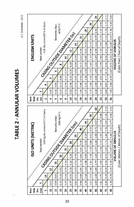
In all cases of annular seal placement, the amount of sealant
actually used should be verified as being adequate to fill the
volume of the annulus being sealed (see Table 2).
20

21
FIGURE 4

22
FIGURE 5

23
FIGURE 6

24
FIGURE 7

25
FIGURE 8

26
FIGURE 9

27
9 COMMINGLING AND LEAKAGE
See Section 4, pages 6 and 7, for definitions of aquifer, artesian
aquifer, commingling and head.
If multiple aquifers are encountered in a well, the well should be
constructed to prevent commingling and leakage of groundwater
by gravity flow or artesian pressure from an aquifer to another
aquifer or to an unsaturated zone that is capable of long term
acceptance of the water. This will prevent the spread of
contaminates or poor quality water to other formations and
prevent loss of aquifer head within an aquifer. There should be no
water moving up or down the well, either inside or outside the
casing or liner when the well is in a completely static (non-pumping)
and recovered condition. Prevention may be accomplished by
placement of additional surface seal depth or utilizing an additional
lower annular seal. (see Figures 11 and 12, pages 31 and 32).
10 CASING AND LINER
See Section 4, pages 6 and 7, for definitions of casing and liner.
Casings and liners should be PVC (polyvinyl chloride) or black steel
pipe meeting the specifications of Table 3, page 30.
PVC casing should be protected from long term exposure to
sunlight (ultraviolet light). Protection may include an outer steel
protector casing, a concrete tile (or masonry box) and lid or cover, a
building, a pump, etc.
All casing should be new or like new. It should be cleaned of any
contaminants and inspected for any mechanical damage, holes,
pitting, etc.
PVC casing should never be driven. If driving steel casing, a drive
shoe is recommended.

28
The casing and or liner diameter should be sized to allow easy
placement of the pumping equipment. Typically, the inside
diameter of the casing and liner in the pump placement interval of
the well should be at least 1 cm [½ inch] larger in diameter than the
largest part of the in-well pump components if the pump
components are less than 10 cm [3.9 inches]. Larger clearances are
always better and should be used with larger pump systems.
CAUTION: If cement grout sealant is used around PVC casing, care
should be taken to prevent PVC exposure to excess heat of
hydration from cement curing that can permanently deform the
pipe. Cement grout placed in excessively large borehole areas (e.g.
caverns, voids, wash-
outs) will result in a
significant increase in
heat that will likely
cause this to happen
which could make
the well unusable,
requiring its proper
decommissioning. If
PVC casing is sealed
using cement, cold
water may be
circulated in the well
bore during the early
curing process
(recommend at least
24 hours) to attempt
to prevent damage
to the casing.
Nevertheless, it is better to use steel casing (if available) when
sealing with cement.
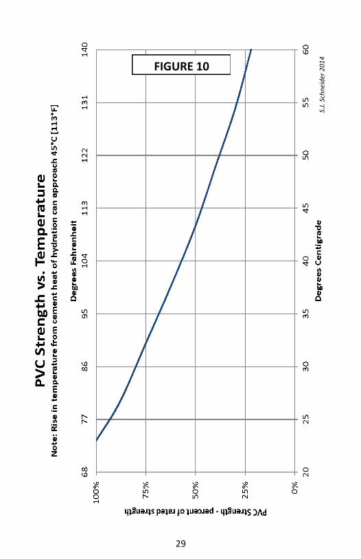
PVC collapsed from excessive heat.
PVC rapidly loses strength with increasing
temperature (see Figure 10, page 29).
29
FIGURE 10
S.J.
Sch
nei
der
20
14

30

31

32

33
11 OTHER WELL MATERIALS
Other well materials, including but not limited to gravel or filter
pack media, annular backfill or filler, screens, packers, plugs and
shale traps should be clean and free of organic material prior to
placement in the well. Proper design, material selection and skilled
installation will ensure a satisfactory well completion for its intend-
ed use. Improper screen or filter pack design is the most common
cause of a sand producing well. Such wells result in premature
pump failure, degradation of surface seals from subsidence, casing
shifting or breaking and poor water quality. These wells are often
abandoned without proper decommissioning. There are many
publications available to assist with the correct design and selec-
tion of screens, filter packs and other unique well materials (see
Appendix I, page 48, and Reference No. 3, page 54).
12 PLUMBNESS AND ALIGNMENT
Water supply well plumbness (drift) and alignment is extremely
important since wells are usually equipped with down-hole pumps
or pumping equipment. Acceptable plumbness and alignment also
facilitates well completion and maintenance.
Unless otherwise specified, the well should be plumb within one
percent of true vertical. In other words, it should not drift from
vertical more than 0.3 meter in 30 meters [1 foot in 100 feet].
There should be no noticeable bends or dog-legs, especially in the
portion of the well wherein pumps or pumping equipment is to be
installed. Excess misalignment makes screen, liner, pump and oth-
er material installation and removal difficult or impossible. In addi-
tion, it causes excess or premature wear of the pump equipment or
well casing or liner. The well alignment shall be such that its screen
assembly, liner(s) and pumping equipment can be freely installed.

34
13 WELL DEVELOPMENT
All water supply wells should be developed to ensure that they do
not produce excessive sand that could cause premature pumping
equipment failure and/or compromise the structural integrity of the
well. Less than 25 milligrams per liter [parts per million] is
recommended. Additional filtration on the surface may still be
desired, especially for drinking water. Development also improves
the efficiency of the well. There are many publications available to
assist with the selection of the proper approach, tools to use and
when to use them during a well’s construction.
14 SURFACE COMPLETION
The area immediately surrounding a well should be sloped away
from the well to drain water from the well vicinity.
If the well is equipped with a hand pump, a raised concrete apron
should be placed around the well. The apron should extend at least
10 cm [4 inches] above the highest ground around the well. The
casing should extend above the concrete apron as far as the
pumping equipment will allow. The apron should extend around
the well at least 1 meter [3 feet] in all directions. The apron should
Well head with good apron and drainage

35
be designed to drain any water, whether from rain or spillage,
away from the well.
If the well is not equipped with a hand pump, the casing should
extend at least 0.3 meter [1 foot] above the highest ground surface
around the well.
All wells should be sealed between the pumping equipment and the
well casing. If the well is equipped with a hand pump and concrete
apron, the pump base in contact with the apron should be sealed to
prevent any liquid from entering.
All wells should be equipped with a vent to prevent vacuum
drawing contaminants into the well. The vent should be screened
to prevent bugs and insects from entering the well. The vent
should be positioned at least 0.3 meter [1 foot] above the concrete
apron or highest ground around the well, whichever is higher. The
vent should be facing downward to prevent any liquid (and
contaminants) from running, or being drawn, into the well through
the vent. The vent should be of a rugged design to prevent damage
from vandalism and the environment.
All wells should be equipped with an access port in order to
measure the water level. The access port should be at least 1.5 cm
[0.6 inch] diameter. The access port should be securely plugged
(e.g. wrench tightened thread or lock) when not being used to
prevent access from unauthorized personnel. Deep wells should be
equipped with a dedicated probe pipe, normally attached to the
pumping equipment, to facilitate water level measurements. Probe
pipes should be at least 1.5 cm [0.6 inch] diameter.
15 DISINFECTION
All wells and the equipment installed in them should be disinfected
prior to their use. Chlorine is a commonly used disinfectant. A 50
mg/l [ppm] concentration is commonly accepted for disinfection.

36
Table 4, page 36 provides suggested quantities of chlorine agents to
achieve 50 mg/l [ppm] initial concentration. Depending on the well
chemistry and other concerns, additional chlorine may be required
to fully effect disinfection. Chlorine disinfectant requires contact
time to be effective. At least 12 hours of contact should be
allowed. Chlorine is heavier than water. Agitation within the well
will result in a better disinfection.

37
Every time in-well equipment is installed or re-installed it should be
cleaned and disinfected prior to installation and use. If the well is,
or even might be, used for human consumption, it should also be
tested for E-coli (see section 16, page 37). Equipment removed
from a well awaiting repair before re-installation should never be
placed directly on the ground and should be protected from
exposure to vegetation, rodents and other animals.
16 TESTING
Wells should be tested for yield (flow rate) and basic potability. An
appropriate down-hole water level measurement device is required
for every well construction or well maintenance project. The static
water level in the well should be measured near the beginning of a
yield test. Typically, yield testing on low capacity, low demand
wells is performed with the permanent pump. Often a simple
Protect pump and drop pipe from direct contact with the ground
during installation and maintenance

38
computation using the time it takes to fill a container of known
volume is used to determine a flow rate. The duration of the test
for small capacity wells should be at least one hour. Large demand
wells (e.g. irrigation, community) should be tested longer than an
hour, sometimes 24 hours or longer if they will are expected to run
continuously for several days. The yield of large demand wells
should be measured using more sophisticated measurement
devices (e.g. flowmeters or orifice tubes). These devices provide a
more accurate determination of the flow rate. In addition, the
pumping water level should be taken frequently throughout the
yield testing of large demand wells in order to graphically
extrapolate the data to forecast long term pumping water level.
Such data is also useful for determining well efficiency and aquifer
characteristics such as transmissivity.
Each well should be tested for potability after all disinfectant has
been thoroughly removed from the well and prior to initial use for
Bucket timing flow from a domestic well
Orifice tube measuring flow from a municipal well

39
human consumption. Potability consists of testing for Escheichia
coli (E-coli). No E-coli shall be present. A simple method to test
for E-coli is to perform a test for coliform bacteria. It there is no
coliform bacteria, there is no E-coli; however, a positive coliform
test does not necessarily mean that E-coli is present. If a coliform
test comes up positive, it is recommend that the well be sampled
and tested again (since it is not uncommon to get a false positive)
or that it be sampled again and specifically tested for E-coli.
Other tests should be considered depending on the intended use of
the well and known or suspected minerals and contaminates in the
area. Such other tests include, but are not limited to: nitrates,
arsenic, fluoride, salinity, radionuclides.
Basic testers available (CW: coliform, chlorine, PH, TDS)

40
17 WELL DECOMISSIONING
All wells that are not completed during construction, are damaged
beyond repair, or are replaced because they are contaminated
should be permanently decommissioned. Permanent
decommissioning should restore the boundaries between aquifers
and the boundary from ground surface to the first aquifer utilizing
sealants specified previously herein. Casing(s) and liner(s) should
be removed during decommissioning if possible and feasible.
Chip bentonite for decommissioning should only be used in un-
cased and un-lined portions of boreholes. Chip bentonite may be
used inside cased portions of a well that has been documented to
have been properly annularly sealed as prescribed herein.
If placing cement grout inside a casing or liner, the casing or liner
shall be thoroughly perforated to permit the grout to migrate
outside of the casing or liner.
Concrete may be used for decommissioning that part of the
uncased borehole that is above the water level in the well at the
time of placement. It may also be used inside the casing but only if
it is used opposite that part of the casing that has been
documented to have a proper seal around it. Concrete may also be
used to decommission dug wells but only from 1 meter [3 feet]
above the static water level and to depths no greater than 15
meters [49 feet].
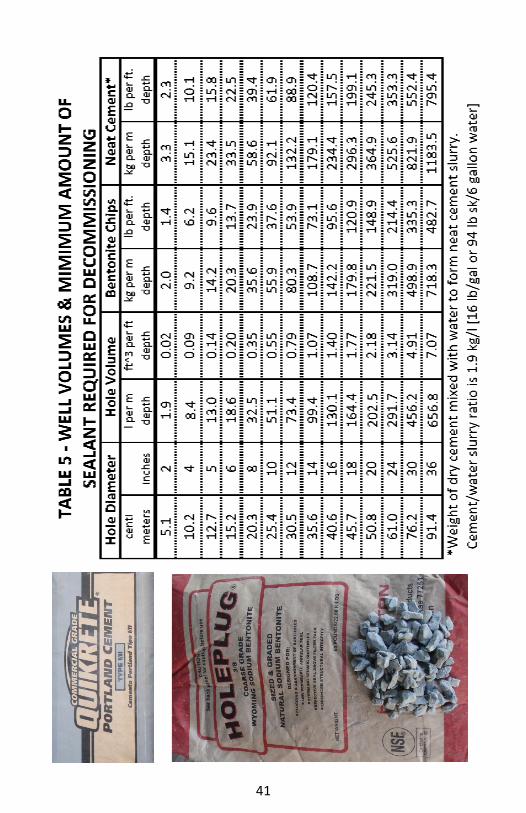
In all cases of decommissioning, the volume of sealant actually
used should be verified as being adequate to fill the volume of the
space being sealed (see Table 5, page 41).
If permanent decommissioning is not desired or feasible, all wells
shall be properly secured to prohibit children from accessing it and
from foreign material or contaminants from entering it.
41

42
18 DOCUMENTATION
WELL RECORD
A log or record should be made and maintained on each well
(including well decommissioning).
Documentation should include:
Well location— Two methods
should be recorded to minimize
error:
GPS (global positioning
system), and
Property legal description or
other locally used documentable
location criteria.
Well identification number or
nomenclature — The unique
number or nomenclature shall be
permanently imbedded or attached
in/on the concrete apron or the
exposed casing (or the pumping equipment if the first two are
not an option). The identification number / nomenclature
should be recorded on all documents containing the other
information specified herein and it should be noted as to where
that identification is located on the well.
Well owner or user — Identify as to whether they are the
owner, user or both.
Well constructor’s name and/or organization.
Depth drilled and depth of completed well.
Formation description by depth, including: predominant
material(s), color, size and hardness or texture.
GPS - Essential tool for documenting well location

43
Annular seal depth and material used.
Depth and height above ground of all casings and liners,
diameters, types of material (e.g. PVC, steel), and schedules or
wall thicknesses.
Full description (material, size, quantity, etc.) and location by
depth of all perforations, screens, pack, and any other
component of the well.
Date and depth to static water level.
Date and results of yield test.
The log or record of each well’s construction details should be filed
in accordance with any local regulations. A copy should also be
provided to those in charge of operating and maintaining the well
A permanent well identification number or nomenclature should be on every well and in related documentation

44
and it should also be filed in a secure central web based repository
that provides public access. (Sample form on next page)
Filings are used to
facilitate the operation
and maintenance of
the well, to aid in the
future proper
decommissioning of
the well, and to
identify and quantify
the availability of
groundwater resources
in the area.
PUMP RECORD
A record should be
created by the pump
installer, and
maintained by the well
owner/operator, of the
current pump installed in the well. The record should contain the
type of pump (e.g. hand, solar submersible, merry-go-round, etc.),
drop pipe and rod dimensions as applicable, depth of set, voltage
and phase if electric powered, manufacturer, model, serial number
and any other pertinent information. (Sample form on page 46)
WATER QUALITY RECORD
Documentation of all water quality tests should be maintained by
the owner/operator. Records should include: Dates and results of
the chemical tests performed, name of individual obtaining the
sample, the source location of the sample, the date that the
sample was taken, name of the laboratory or individual performing
the analysis, and test method(s) utilized.

45

46

47
19 PERSONNEL SAFETY
Well construction and pump installation usually involves operation
of power driven equipment with part of the machinery operating
over the operators head. Tools and equipment can be heavy and
are often dropped. Dust is often created during the drilling
operation and sealant materials may give off harmful dust during
their use. Personal protection equipment (PPE) should always be
used as appropriate for the operation.
PPE required would likely include:
Hard Hat Eye Protection
Gloves Leather Shoes
Dust Mask Hearing Protection
48
APPENDIX I
Filter (gravel) Pack – Analysis and Selection
Sand Aquifer — Procedures
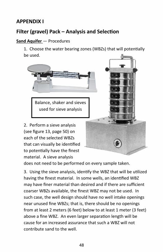
1. Choose the water bearing zones (WBZs) that will potentially
be used.
2. Perform a sieve analysis
(see figure 13, page 50) on
each of the selected WBZs
that can visually be identified
to potentially have the finest
material. A sieve analysis
does not need to be performed on every sample taken.
3. Using the sieve analysis, identify the WBZ that will be utilized
having the finest material. In some wells, an identified WBZ
may have finer material than desired and if there are sufficient
coarser WBZs available, the finest WBZ may not be used. In
such case, the well design should have no well intake openings
near unused fine WBZs; that is, there should be no openings
from at least 2 meters (6 feet) below to at least 1 meter (3 feet)
above a fine WBZ. An even larger separation length will be
cause for an increased assurance that such a WBZ will not
contribute sand to the well.
Balance, shaker and sieves
used for sieve analysis
49
4. Using the formation sieve analyses of the WBZ with the
finest material that will be exposed, multiply its 70% retained
size by a factor of 4 to 6. The result is the target value range for
the 70% retained size of the filter pack.
5. Perform a sieve analysis on any candidate filter pack material
that does not already have an analysis provided. Candidate
filter pack material should:
a. Be clean,
b. Have well rounded grains,
c. Contain at least 90% quartz or silica, and
d. Be uniform in size. A uniformity coefficient (UC - the ratio
of the 40% retained size to the 90% retained size) of less than
2.5 is preferred.
6. From the
candidate filter pack
materials, select one
that has a 70% size
within the target value
range identified in step
4 above; coarser is
preferred if the UC is
<2.5.
7. Select a well intake
opening (slot width)
that is no larger than
the 90% retained size of the selected filter pack material.
8. Construct the well such that the filter pack thickness is no
less than 25 mm [1 inch] at any point around the well intake
and no more than 100 mm [4 inch]. A thick pack is more
difficult to develop and a thin pack is more difficult to properly
place (e.g. bridging or particle segregation may occur). The
preferred thickness range is 40 mm [1.5 inch] to 70 mm [3 inch].
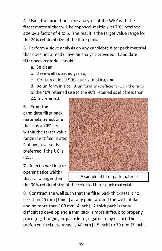
A sample of filter pack material

50
Figure 13

51
Sand & Gravel Aquifer
Use the following alterations to the Sand Aquifer procedures:
If the percent of sand in the formation is estimated to be
greater than 50% and the majority of the sand is less than 2 mm
[.08 inch], then in the sieve analysis (Sand Aquifer procedure
#2, page 48), remove from consideration all material retained
on a 10 mm [3/8 inch] and larger sieve.
If the percent of sand in the formation is estimated to be
about equivalent to the amount of gravel, or there is more
gravel than sand and the majority of the sand is greater than
0.5 mm [.02 inch], then in Sand Aquifer procedure #4, page 49,
make the 70% multiplication factor 6 to 8 in lieu of 4 to 6.
Soil & Aggregate Terminology and Size
Reference No.2, page 54: Unified Soil Classification System
Silts and clays Less than .08mm (.003in)
Fine sand .08mm (.003in) up to .43mm (.02in)
Medium sand 43mm (.02in) up to 2.0mm (.08in)
Coarse sand 2.0mm (.08in) up to 4.8mm (.19in)
Fine gravel 4.8mm (.19in) up to 19mm (.75in)
Coarse gravel 19mm (.75in) up to 75mm (2.9in)
Cobbles 75mm (2.9in) up to 300mm (11.8in)
Boulders greater than 300mm (11.8in)

52
APPENDIX II
Well Design Pros and Cons
Consolidated Formation Well Design Comparison
Type A
A liner is optional (although it is recommended).
The liner may be removed, if required, for future well alteration or rehabilitation work.
Formation and water bearing zone information should be obtained before installing and sealing the casing to ensure that they are properly located.
Type B
Accommodates a single diameter borehole from top to bottom which may be beneficial using a fluid stabilized borehole drilling method.
May cost more than a Type A design.
Bacteria may accumulate in the annular area between the seal and the well intake; if so, it may be difficult to eliminate them.
Unconsolidated Formation Well Design Comparison
Naturally Developed well
Requires very accurate sampling, sieve analysis and screen selection in order to prevent excessive sand pumping. Thin layers of fine sand or silt often create a sand production problem.
May be constructed with a uniform inside diameter for full depth (i.e. screen or perforations are same size as casing) or with a telescoping well intake structure (e.g. pull back casing to expose well intake).
Usually has a lower initial construction cost than a filter packed design.
Becoming less commonly used with the higher percentage of long-term successes being experienced using filter pack designs.

53
Type I Filter Pack
Least expensive filter pack design.
Uniform inside diameter for the full depth provides for easier development and future rehabilitation.
Pump may be easily installed to the very top of the well intake thereby maximizing available drawdown.
Does not provide for replenishment of filter pack. Not recommended for shallow aquifers or situations where limited height is available for reserve filter pack.
Annular seal should not be completed until development is complete. May require a temporary casing to be used in the seal interval to maintain borehole integrity until the seal is placed.
Type II Filter Pack
Can replenish pack (usually requires pump removal).
Difficult to measure filter pack level, especially with a pump in the well.
More expensive than a Type I Filter Pack design.
Non-uniform inside diameter increases the difficulty and cost of development and future rehabilitation.
Depth of the pump chamber (i.e. the inside diameter of the well that is above the top of the well intake structure) is less than would be available with a Type I or a Type III Filter Pack design.
Type III Filter Pack
Most expensive design.
Accommodates monitoring of the filter pack level from the surface without pump removal.
Accommodates replenishment of the filter pack from the surface without pump removal.
Uniform inside diameter for the full depth makes for easier development and future rehabilitation.
A pump can be installed to the very top of well intake thereby maximizing available drawdown.

54
REFERENCES (listed alphabetically)
1. Anderson, K. E., Ground Water Handbook
2. ASTM International, Standard Practice for Classification of Soils for Engineering Purposes (Unified Soil Classification System) ASTM D2487
3. Driscoll, F.G., Groundwater and Wells Second Edition
4. National Ground Water Association, ANSI/NGWA-01-14 Water Well Construction Standard
5. National Ground Water Association, Lexicon of Groundwater and Water Well System Terms
6. Whinery, J., A Well Construction Cost-Benefit Analysis: For Water Supply Well Guidelines for use in Developing Countries
RESOURCES
National Ground Water Research and Educational Foundation (NGWREF) “National Ground Water Research and Educational Foundation, also known as NGWREF, is focused on conducting educational, research, and other charitable activities related to a broader public understanding of groundwater.” http://www.ngwa.org/Foundation
Rural Water Supply Network (RWSN)
“RWSN is a global network of professionals and practitioners working to raise standards of knowledge and evidence, technical and professional competence, practice and policy in rural water supply and so fulfil the vision of sustainable rural water services for all.” http://www.rural-water-supply.net
Water, Engineering and Development Centre (WEDC) of Loughborough University “The Water, Engineering and Development Centre is one of the world’s leading education and research institutes for developing knowledge and capacity in water and sanitation for sustainable development and emergency relief.” http://wedc.lboro.ac.uk

55
ABOUT THE PRINCIPAL AUTHOR & EDITOR
Stephen J. Schneider (Steve) manages the drilling division at
Schneider Water Services of St. Paul, OR, USA a contracting
business employing approximately 25 people in water related
activities including: drilling, pumps & water systems installations,
water treatment and service. Raised in the industry, he continues
to work for the same company for over 37 years.
With a BS degree in mechanical engineering from Oregon State
University, Steve worked for the US Department of Defense as a
civilian engineer, which included writing/editing many technical
specifications. He has drilling licenses in the states of Oregon,
Washington and Idaho and pump installer licenses in Oregon and
Washington. He is a National Ground Water Association (NGWA)
Master Ground Water Contractor (MGWC).
Steve has presented educational seminars and workshops via
Webinars and in person at NGWA Expos, NGWA Groundwater
Summits, Oregon Ground Water Association (OGWA) conventions,
WEDC International Conference, and other events. He was the first
non-government presenter of required continuing education
related to well construction rules in Oregon.
Steve has also served on:
Oregon Ground Water Advisory Committee, including as Chair
Oregon well construction Rules Advisory & other committees
NGWA Standards Development Oversight committee
NGWA Developing Countries Interest Group, including as Chair
NGWA Policy & Code committee, including as Chair
NGWA McEllhiney Lecturer Task Force
NGWA initial strategic planning session
NGWA item writing sessions
OGWA board of directors, including as President
OGWA government affairs committee, including as Chair

56
OGWA meetings/conference committees
Pacific NW Ground Water Association, including as Vice
President
National Ground Water Research & Education Foundation
(NGWREF), 2011-2014 as President
Steve continues to be active in NGWA’s Developing Countries
Interest Group and has made several trips to, and continues to
work with, a mission in Mexico developing groundwater supplies
for the indigenous Tarahumara Indians.
PDF version of this book and a related cost-benefit analysis are available at:
http://www.schneiderwater.com/pdf/Hydrophilanthropy_Well_Guidelines.pdf
Also available at schneiderwater.com Click on Hydrophilanthropy
Click on the Well Guidelines book image
For more information, contact the principal author: Stephen J. Schneider—[email protected]
“As of January 2012, the National Ground Water
Association congratulates this initiative and looks
forward to its continuing evolution to capture
best practices in groundwater protection and in
water well design, construction, and operation
and maintenance.”

ENDORSEMENTS and/or FINANCIAL SUPPORT provided by:
John Gregg, Gregg Drilling & Testing, Inc. John & Jan and Doug Wagner, Moody’s of Dayton, Inc.
Steve & Miriam Schneider
and the following organizations
ISBN 978-0-9884685-3-5
endorsement inside back cover
American Water Resources Association