watermarking using decimal sequences
TRANSCRIPT

Louisiana State UniversityLSU Digital Commons
LSU Master's Theses Graduate School
2004
Watermarking using decimal sequencesNavneet Kumar MandhaniLouisiana State University and Agricultural and Mechanical College, [email protected]
Follow this and additional works at: https://digitalcommons.lsu.edu/gradschool_theses
Part of the Electrical and Computer Engineering Commons
This Thesis is brought to you for free and open access by the Graduate School at LSU Digital Commons. It has been accepted for inclusion in LSUMaster's Theses by an authorized graduate school editor of LSU Digital Commons. For more information, please contact [email protected].
Recommended CitationMandhani, Navneet Kumar, "Watermarking using decimal sequences" (2004). LSU Master's Theses. 3915.https://digitalcommons.lsu.edu/gradschool_theses/3915
WATERMARKING USING DECIMAL SEQUENCES
A Thesis
Submitted to the Graduate Faculty of the Louisiana State University and
Agricultural and Mechanical College in partial fulfillment of the
requirements for the degree of Master of Science in Electrical Engineering
in
The Department of Electrical and Computer Engineering
By Navneet Kumar Mandhani
Bachelor of Engineering, Andhra University, 2002 Visakhapatnam, India
August 2004

ii
Acknowledgements I would like to acknowledge certain people who have encouraged, supported and helped
me complete my thesis at LSU.
I am very grateful to my advisor Dr. Subhash C. Kak for his guidance, patience and
understanding throughout this work. His suggestions, discussions and constant
encouragement have helped me to get a deep insight in the field of Watermarking. I
would like to thank Dr. Suresh Rai and Dr. Xue Bin Liang for sparing their time to be a
part of my thesis advisory committee. I am very thankful to Dr. Stevan G. Hall for all his
support, financial and technical throughout my thesis. I take this opportunity to thank my
friends Archit, Pradeep, Naveed, Sameer, Radhika and Pallavi for their help and
encouragement. I would also like to thank all my friends here who made my stay at LSU
an enjoyable and a memorable one.

iii
Table of Contents Page Acknowledgements…………………………………………………………………. ii List of Tables…….…………………………………………………………………...v List of Figures……..………………………………………………………................vi Abstract…….………………………………………………………………………...ix Chapter 1. Introduction……………………………………………………………………….1 1.1 Background………………………………………………………………….. .2 1.2 Cryptography, Steganography and Watermarking………………………….. .2 1.2.1 Cryptography………………………………………………………….. .2 1.2.2 Steganography………………………………………………………… .3 1.2.3 Watermarking…………………………………………………………. .5 1.3 Applications of Watermarking...………………………………………...........7 1.4 Outline of Thesis..…………………………………………………………….8 2. Basic Watermarking Techniques…………..…………………………………… 10 2.1 Requirements of a Good Watermark……………………………………...... 10 2.2 Basic Watermarking Techniques…………………………………………… 11 2.2.1 Visible Watermarking….…………………………………………….. 11 2.2.2 Invisible Watermarking…..……………………………………….. … 12 3. Watermarking Using PN Sequences………….…………………………………16 3.1 What is CDMA? ………………………….………………………………...16 3.2 PN Sequences……………………………….……………………………....17 3.3 Properties of PN Sequences………………….………………………….…..19 3.4 Watermarking Using PN Sequences…………………………………….…..21 3.4.1 Embedding and Decoding………………………………………….….22 3.4.2 Observations…………………………………………………………..30 4. Watermarking Using Decimal Sequences…...………....……………………….31 4.1 Introduction………………………………..….…………………………… 31 4.2 Properties of Decimal Sequences…..…………………………………….....31 4.3 Generation of Decimal Sequences………………………………………......36 4.4 Watermarking Using Decimal Sequences…………………………………..39 4.4.1 Embedding and Recovery Using D-Sequences……………………....39 5. Analysis of Results………………………………………………...……………45 5.1 Performance Analysis…………………………………………...…………. 45 5.2 Correlation Analysis……………………………………………...………... 48 5.3 Observations……………………………………………………….......……51

iv
6. Conclusions……………………………………………………………………. 55 Bibliography……………………………………………………………………... 56 Vita………………………………………………………………………………..58

v
List of Tables 3.1 Outputs of a 3-stage shift register…………………………………………… 19 4.1 Sample results for various prime numbers used to generate d-sequences for watermarking………………………………………………………………… 44 5.1 Mean and standard deviation analysis for 256 × 256 Lena image………….. 51

vi
List of Figures 1.1 Cryptography for secure communication…………………………………...... 3 1.2 A Steganographic system……........................................................................... 4 1.3 Digital Watermarking – Embedding…………………………………………. 6 1.4 Digital Watermarking – Decoding…………………………………………… 6 2.1 Lena 256 × 256 Image……………………………………………………….. 12 2.2 Watermark Image (Visible watermark)………………………………………. 12 2.3 Watermarked Image (Visible watermark)……………………………………. 12 2.4 Lena 256 × 256 Image……………………………………………………….. 14 2.5 Watermark Image (LSB Substitution)……………………………………….. 14 2.6 Watermarked Image………………………………………………………….. 14 2.7 Watermark recovery…………………………………………………………. 14 3.1 Linear Feedback Shift Register………………………………………………...18 3.2 Embedding process…………………………………………………………... 22 3.3 Decoding process…………………………………………………………….. 23 3.4 Lena 256 × 256 image……………………………………………………….. 28 3.5 Watermarked image with gain 3……………………………………………… 28 3.6 Watermarked image with gain 5……………………………………………… 29 3.7 Watermarked image with gain 3 ( High pass filtered Lena)…………………. 29 3.8 Original watermark…………………………………………………………… 29 3.9 Recovered watermark for gain 3……………………………………………… 29 3.10 Recovered watermark for gain 5……………………………………………...30 3.11 Recovered watermark for gain 3 (for high pass lena)…………………………30

vii
4.1 Autocorrelation graph for q = 293……………………………………………..34 4.2 Cross correlation graph for q = 5 with zero shift………………………………35 4.3 Generation of d-sequences……………………………………………………....37 4.4 Grey scale Lena image…………………………………………………………..40 4.5 Watermark object………………………………………………………………..40 4.6 Embedding output for q = 283…………………………………………………..40 4.7 Decoding output for q = 283…………………………………………………….40 4.8 Embedding output for q = 167…………………………………………………..41 4.9 Decoding output for q = 167…………………………………………………….41 4.10 Embedding output for q = 263………………………………………………….41 4.11 Decoding output for q = 263…………………………………………………... 41 4.12 Embedding output for q = 293………………………………………………….42 4.13 Decoding output for q = 293………………………………………………........42 4.14 Embedding output for q = 1879………………………………………………...42 4.15 Decoding output for q = 1879…………………………………………………..42 4.16 Watermarked image for circular shift = 50……………………………………..43 4.17 Retrieved watermark…………………………………………………………....43 4.18 Watermarked image for circular shift = 146…………………………………....43 4.19 Retrieved watermark…………………………………………………………....43 5.1 Embedding output for q = 277………………………………………………….45 5.2 Decoding output for q = 277…………………………………………………....45 5.3 Autocorrelation for q = 277…………………………………………………….. 46 5.4 Embedding output for q = 257…………………………………………………..47

viii
5.5 Decoding output for q = 257…………………………………………………….47 5.6 Autocorrelation for q = 257……………………………………………………..47 5.7 Correlation graph for q = 293…………………………………………………...49 5.8 Correlation graph for q = 277…………………………………………………. 50 5.9 Correlation graph for q = 257…………………………………………………. 50

ix
Abstract This thesis introduces the use of decimal sequences in watermarking to hide
information for authentication. The underlying system is based on code division multiple
access (CDMA), which is a form of spread spectrum communication. Different
algorithms for the use of decimal sequences have been formulated for use in black and
white images. The watermark is spread across the carrier image by using the d- sequences
of optimal period and retrieval is made by the use of correlation. Matlab version 6.5 was
used to implement the algorithms discussed in this thesis. The advantage of using d-
sequences over PN sequences is that one can choose from a variety of prime numbers
which provides a more flexible system. Different methods for adding the random
sequence to the image were investigated and results for random shifts and cyclic shifts
have also been discussed.

1
Chapter 1 Introduction
Cryptography and steganography have been used throughout history as means to
add secrecy to communications during times of war and peace [6]. Some of the early
methods to hide information include text written on wax-covered tablets, invisible writing
using invisible ink and shaving the head of a messenger and tattooing the message on the
scalp. In World War II null ciphers were used in which the secret was camouflaged in an
innocent sounding message as in the example below [22]
Apparently neutral’s protest is thoroughly discounted and ignored. Islam hard hit. Blockade issue affects pretext for embargo on byproducts, ejecting suets and vegetable oils.
Taking the second letter in each word the following message emerges:
Pershing sails from NY June 1
As technology developed and detection methods improved, more effective
methods of hiding information were developed. The Germans invented microdot
technology for covert communication in 1941. In microdots, the messages were neither
hidden nor encrypted but their size was too small to be seen by the naked eye [22].
Advances in microdot technology still continue to this day, the latest development being
the embedding of a message in a strand of DNA by the use of the technique of genomic
steganography [23].
With the advent of the internet, steganography has found new applications. But, at
the same time it is also vulnerable to more powerful attacks since the medium is
relatively insecure. To overcome this limitation, watermarking comes into picture. The

2
chief difference between the two techniques is the superior robustness capability of
watermarking schemes.
The following sections explain the basic concepts of cryptography, steganography
and watermarking. It also lists some of the most common applications of watermarking in
today’s world.
1.1 Background
Digital watermarking includes a number of techniques that are used to
imperceptibly convey information by embedding it into the cover data [1]. There has
always been a problem in establishing the identity of the owner of an object. In case of a
dispute, identity was established by either printing the name or logo on the objects. But in
the modern era where things have been patented or the rights are reserved (copyrighted),
more modern techniques to establish the identity and leave it untampered have come into
picture.
Unlike printed watermarks, digital watermarking is a technique where bits of
information are embedded in such a way that they are completely invisible. The problem
with the traditional way of printing logos or names is that they may be easily tampered or
duplicated. In digital watermarking, the actual bits are scattered in the image in such a
way that they cannot be identified and show resilience against attempts to remove the
hidden data [1].
1.2 Cryptography, Steganography and Watermarking
1.2.1 Cryptography
Cryptography as the study of secret (crypto) writing (graphy) can be defined as
the science of using mathematics to encrypt and decrypt data back [2]. It allows two

3
people, commonly known as Alice and Bob, to communicate with each other securely.
This means that an eavesdropper known as Eve will not be able to listen in on their
communication. Cryptography also enables Bob to check that the message sent by Alice
was not modified by Eve and that the message he receives was really sent by Alice [3].
A message is known as a plaintext or cleartext. The method of disguising the
plaintext in such a way as to hide its information is encryption and the encrypted text is
also known as a ciphertext. The process of reverting ciphertext back to its original text is
decryption. This is shown in figure 1.1 [4].
Figure 1.1 Cryptography for secure communication
1.2.2 Steganography
While cryptography is about protecting the content of the messages,
steganography is about concealing their very existence. Steganography comes from a
Greek word that means covered writing (stego = covered + graphy = writing) [5].
Examples can be thought as messages exchanged between drug dealers via emails
in encrypted forms, or messages exchanged by spies in covert communication.
Steganography hides the fact that the communication ever occurred as shown in Figure
1.2.

4
Let us consider that Alice, who wants to share a secret message m with Bob,
selects randomly a harmless message or a cover object C. The message to be shared is
then embedded into C, by using key K (called stego-key), and the cover object C is
transformed to stego object S. This stego object can be transmitted to Bob without raising
any suspicion. This should be done in such a way that a third party knowing only the
apparently harmless message S cannot detect the existence of the secret. The cover object
could be any data such as image files, written text or digital sound. In a perfect system, a
normal cover object should not be distinguishable from the stego object, neither by a
human nor by a computer looking for statistical patterns [1].
Figure 1.2 A steganographic system
Alice transmits the stego object S to Bob over an insecure channel. Bob can
reconstruct the message m by using the same key K as used by Alice during embedding
the message in the cover object. The extraction process should not need any knowledge
of the cover object.
Cover Object
C
Message m
Stego Object
S
Stego Object
S
Message m
Untrusted Channel
Stego key K
5
Any person watching the communication should not be able to decide whether the
sender is sending covers with messages embedded into them. In other words, a person
with a number of cover objects C1, C2, ……, Cn should not be able to tell which cover
object Ci has the message embedded in it, and the security of invisible communication
lies in the inability to distinguish cover objects from the stego objects [1] [5]. However,
not all the cover objects can be used to hide the data for covert communication, since the
modifications done after the data is hidden should not be visible to anyone not involved
in the communication. The cover object needs to have sufficient redundant data, which
can be replaced by secret information [1].
1.2.3 Watermarking
Although steganography and watermarking both describe techniques used for
covert communication, steganography typically relates only to covert point to point
communication between two parties [6]. Steganographic methods are not robust against
attacks or modification of data that might occur during transmission, storage or format
conversion [1].
Watermarking, as opposed to steganography, has an additional requirement of
robustness against possible attacks. An ideal steganographic system would embed a large
amount of information perfectly securely, with no visible degradation to the cover object.
An ideal watermarking system, however, would embed an amount of information
that could not be removed or altered without making the cover object entirely unusable.
As a side effect of these different requirements, a watermarking system will often trade
capacity and perhaps even some security for additional robustness [5].
The working principle of the watermarking techniques is similar to the
steganography methods. A watermarking system is made up of a watermark embedding
6
system and a watermark recovery system. The system also has a key which could be
either a public or a secret key. The key is used to enforce security, which is prevention of
unauthorized parties from manipulating or recovering the watermark. The embedding and
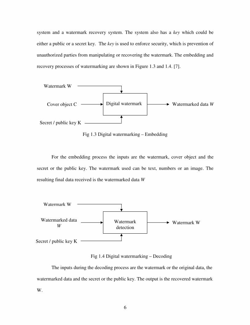
recovery processes of watermarking are shown in Figure 1.3 and 1.4. [7].
Fig 1.3 Digital watermarking – Embedding
For the embedding process the inputs are the watermark, cover object and the
secret or the public key. The watermark used can be text, numbers or an image. The
resulting final data received is the watermarked data W
Fig 1.4 Digital watermarking – Decoding
The inputs during the decoding process are the watermark or the original data, the
watermarked data and the secret or the public key. The output is the recovered watermark
W.
Watermarked data W
Watermark W
Digital watermark
Watermark W
Cover object C
Secret / public key K
Watermarked data W
Watermark detection
Watermark W
Secret / public key K
7
1.3 Applications of Watermarking
The requirements that a watermarking system needs to comply with depends upon the
specific type of application. A few most common applications involve:
1. Owner Identification: The owner identification can be printed on the covers or
mentioned somewhere on the item. Examples are the identification mark of an
audio company on the CD case or the mark of the paper manufacturer on top
corner of the paper. These types of watermarks can be easily removed by
cropping the image or by tearing the part that has the identification. Digital
watermarking helps to overcome this problem by embedding the watermark in the
form of bits and forming an integral part of the content. The device reads the CD
and identifies the watermark. For having further access to the CD the owner
should have a license or he should have paid a fee to access the copyrighted work.
2. Copy Protection: To prevent the data from being copied a watermark can be
introduced in the data with a copy protect bit. When the copying device reads the
data, the watermark detecting circuitry should detect the watermark and stop
recording. This would need all the copying machines to have the watermark
circuitry to identify the watermark and act accordingly [1].
3. Broadcast Monitoring: A commercial advertisement may be watermarked by
putting a unique watermark in each video or sound clip prior to broadcast.
Automated monitoring systems can then receive broadcasts and check for these
watermarks, identifying when and where each clip appears. This proves very
helpful for the advertisers as they actually pay for only the number of times the
advertisement was actually relayed [10].

8
4. Medical applications: Names of the patients can be printed on the X-ray reports
and MRI scans using techniques of visible watermarking. The medical reports
play a very important role in the treatment offered to the patient. If there is a mix
up in the reports of two patients this could lead to a disaster.
5. Fingerprinting: A fingerprinting technique can be used to trace the source of
illegal copy. Every copy available can be watermarked with a unique bit
sequence. Now, if a copy is made illegally the source can be easily tracked since
each original copy had a unique bit sequence embedded into it [8].
6. Data Authentication: A given set of data (images) can be easily tampered
without even being detected. To avoid this and maintain the originality of the
image a watermark like signature, a set of words, may be embedded into the
image. If the image is now being tampered it can be easily detected as the pixel
values of the embedded data would change and not match the original pixel
values. If the image is being copied it would lose its authentication as the
embedded data would not be copied along with the image.
1.4 Outline of the Thesis
The central idea of this thesis is to develop algorithms for using decimal
sequences in watermarking for application to black and white images. Chapter 2
introduces the basic watermarking techniques like visible watermarking and least
significant bit substitution (LSB). Some of the possible attacks are also discussed. Chapter
3 starts with a brief background on how code division multiple access (CDMA) is used
for classical watermarking based on pseudonoise (PN) sequences. Some examples of
such watermarking using different techniques to shift the sequence are presented and the
chapter concludes with a brief section on discussion of results and drawbacks and how
9
they can be improved by using decimal sequences. Chapter 4 focuses on properties of
decimal sequences, followed by methods to generate them. Then it shows how to embed
and recover hidden information using decimal sequences in black and white images for
different shifts and prime numbers. Some sample outputs are presented. Chapter 5 deals
with analysis of results obtained using decimal sequences. It compares the output
obtained for various prime numbers with periods of (q-1), (q-1)/2, (q-1)/3… and also
compares the correlation graphs for good and bad recovery of watermark to throw more
light on the analysis of results. This chapter ends with conclusions and future scope for
study.

10
Chapter 2 Basic Watermarking Techniques
This chapter presents requirements for a good watermark and discusses some
basic techniques like visible watermarking and the least significant bit substitution (LSB)
method.
2.1 Requirements of a Good Watermark
1) Robustness: Robustness means that the watermarking scheme employed should
be able to preserve the watermark under various attacks. The attack could be
anything like rotation, translation, cropping, scaling or passing the image through
various types of filters. There might be some noise introduced by this processing
but this should not affect the retrieval of the watermark
2) Quality of the image: Watermarking should be done in a way such that it does
not affect the quality of the image or the hidden data after watermarking. The
changes in the image should not be noticeable to the naked eye.
3) Payload capacity of the image: It is very important to find the maximum amount
of information that can be safely hidden in an image. Various applications have
different sizes of the data that is to be hidden. This directly affects the robustness
and the perceptual impact. If too much of the data is hidden in the image (much
more than the payload capacity) it is harmful for the quality of image as the
resolution of the images reduces drastically.
4) Reliability of the watermark: There is always a possibility that the user knows
the exact algorithm for detecting and rendering the watermark inactive. The only
way to secure the watermark then lies in the selection of the key used for
watermarking. Now, even if the user on the other side knows the exact algorithm

11
it should be practically impossible to find the exact key to match with the one
during embedding. This counts for the reliability or strength of the watermark.
2.2 Basic Watermarking Techniques
Watermarks do not always need to be hidden. Watermarking can be broadly
classified in two categories:
• Visible watermarking
• Invisible or imperceptible watermarking
Most of the literature has focused on the invisible digital watermarking as it has
more applications in today’s digital world. Visible digital watermarks are strongly linked
to the original paper watermarks that have been traced back to the end of 13th century [1].
2.2.1 Visible Watermarking
Visible watermarking was the first and most primitive way of watermarking. In
this method the cover object is taken and the watermark in added on it. This makes the
watermark visible on the cover object. This was good for identification purposes but not
for steganography.
Visible watermarks were created by using Lena’s images as the cover images.
These images were 8-bit gray scale images. The watermark was chosen as a monochrome
image exactly of the same size as the cover object. The watermarked image was achieved
by changing the pixel intensity values in the cover image corresponding to white pixels in
the watermark.
Though visible watermarking has been used since a very long time it is not a
secure form of watermarking for applications such as copy protection and copywriting.
The algorithm used for visible watermarking cannot be kept secret. This form of

12
watermarking could only be used for owner identification purposes. For all other
applications invisible watermarking is used.
Fig 2.1 Lena 256x256 Image Fig 2.2 Watermark Image
Fig 2.3 Watermarked Image
2.2.2 Invisible Watermarking
Invisible watermarking can be implemented by using a number of techniques. The
simplest technique used for hidden watermarking is to hide the message bits in the Least

13
Significant Bits (LSB) of the cover object. The advantage with this method is that even if
a part of the stego image is cropped the receiver can still get the required message, as the
message is embedded a number of times. The message for this case is considered to be
very small as compared to the cover object.
For example, for an 8 bit file, each pixel is represented by 8 bits:
• 10001100
• The most significant bits (MSB) are to the left and the least significant bits (LSB)
are to the right.
• If you change the MSB it will have a big impact on the color, however, if you
change the LSB, it will have minimal effect.
Now to take this method a step further, if we change only 1 or 2 least significant
bits in the image, it will have a minimal effect because the human eye can only detect
around 6 bits of color. In other words, the human eye could not tell the difference of the
last 2 bits being changed. For example, if we take 10001100 and change it to 10001111
or 10001110, it will all seem like the same color to the human eye. So we would only
embed data in those bits. An example of this is:
If the message converted to binary is 1101 0010, the first 8 pixels will be
modified as follows:
- 1100 0101 becomes 1100 0111
- 1111 0010 becomes 1111 0001
- 1010 1111 becomes 1010 1100
- 0010 0010 becomes 0010 0010

14
Fig 2.4 Lena 256×256 image Fig 2.5 Watermark image
(LSB Substitution)
Fig 2.6 Watermarked Image Fig 2.7 Watermark recovery
Drawbacks
The LSB substitution method can be very powerful when subjected to cropping or
any of the filters. Even if most of the multiple watermarks are lost in those attacks the
retrieval of a single watermark would be considered as a success. But the simplest attack

15
to render the watermark useless would be to change all the least significant bits as 1. One
more fact under consideration should be that once the algorithm is discovered by the
attacker it would be easy for him to change the watermark.
This system has a major drawback as it cannot use a key to hide the data. The
pseudo random number generator can be used to generate the PN sequences according to
a given key that helps to determine the pixel positions where the data can be embedded
safely in the cover object.

16
Chapter 3 Watermarking Using PN Sequences
To overcome the limitations in watermarking due to methods like LSB
substitution and to make the system more robust against attacks, the watermark can be
spread across the cover object by using more number of bits than the minimum required.
This scheme of hiding the data uses the concepts of code division multiple access
(CDMA). This technique ensures the survival of watermark under various attacks due to
redundancy. Each of the data bits is represented by using a large number of bits out of
which a significant portion may be lost without totally losing the watermark information.
3.1 What is CDMA?
The CDMA technique is a spread spectrum technique, that spreads the transmitted
or the narrowband message over a wide frequency band, which is much wider than the
actual minimum bandwidth required and this large bandwidth signal is called as the
spreading signal. One method of widening the bandwidth is by use of modulation.
Pseudorandom sequences or the PN sequences are used as the spreading sequences. For
watermarking application, a pseudorandom number generator is used to determine the
pixels for embedding the watermark data using a “seed” or a “key”.
Example: Consider that “A” wants to transmit ‘0’ or ‘1’. A has a code word
assigned to it. If A wants to transmit 1 then it sends the codeword else it sends the
complement of the codeword.
A’s codeword = 1 -1 -1 1 -1 1
To send a 1 bit A sends the codeword = 1 -1 -1 1 -1 1
To send a 0 bit A sends the complement of the codeword = -1 1 1 -1 1 -1

17
At the receiver as the receiving party knows that A has transmitted the data and has
access to the codeword it can detect whether the transmitted bit was a 1 or a 0.
At the receiver: (A’s codeword) × (received bit pattern)
If 1 is sent : (1 -1 -1 1 -1 1) × (1 -1 -1 1 -1 1) = 6
If 0 is sent : (1 -1 -1 1 -1 1) × (-1 1 1 -1 1 -1) = -6
If 6 is the sum then the receiver knows that bit 1 was transmitted by A and if -6 is the sum
then a 0 was transmitted.
One might think that using spread spectrum technique is an apparent waste of
spectrum. But there are a few things gained by this wastage.
• Immunity from noise and multipath distortion.
• Can be used for hiding and encrypting signals, this property helps in the principle
of watermarking using CDMA.
• Several users can use independently the same higher bandwidth with very little
interference.
• The low values of the autocorrelation and cross correlation of PN sequences make
them a useful tool for watermarking.
3.2 PN Sequences
A pseudorandom noise (PN) sequence is a sequence of binary numbers, e.g. ±1,
which appears to be random, but is in fact perfectly deterministic. The sequence appears
to be random in the sense that the binary values and groups or runs of the same binary
value occur in the sequence in the same proportion, if the sequence were being generated
based on a fair "coin tossing" experiment. In the experiment, each head could result in
one binary value and a tail the other value.

18
Pseudorandom sequences can be generated by using a Linear Feedback Shift
Register (LFSR) circuit i.e. when a shift register has a non-zero initial state and the output
is fed back to the input, the unit acts as a periodic shift register [11].
Example:
Figure 3.1 shows a LFSR that uses a three stage shift register where the second
and the third cells are tapped and modulo-2 added and fed back to the first stage
M1 = M2 M3
The contents of the shift register are shifted with each clock pulse. The output of
the LFSR is taken from the m3 stage. The outputs of the three shift registers in shown in
the Table 3.1 below.
The output from the Linear Feedback Shift Register is a seven bit sequence 1 1 1
0 0 1 0, which repeats periodically thereafter. In general the period is
N = 2n – 1
Where, N is the period and n is the number of shift registers.
If appropriate feedback tap connections are made, then an n–bit shift register can
produce a maximal length sequence using the above equation. In fact, the above sequence
1 1 1
Clock Pulses
Figure 3.1. Linear Feedback Shift Register
Output

19
generated for a three feedback shift register stage is a maximum length (M) sequence.
The maximum length sequences are also known as the pseudonoise or the PN sequences.
Table 3.1 Outputs of 3 shift registers
M1 M2 M3
1 1 1
0 1 1
0 0 1
1 0 0
0 1 0
1 0 1
1 1 0
1 1 1
3.3 Properties of PN Sequences
Maximum length sequences have the following properties [12]:
• Except the zero state, all of the 2n possible states will exist during the sequence
generation.
• Balance Property: For each sequence generated by the feedback shift registers
the number of ones and zeros is approximately equal.
• Run Property: A run is defined as a sequence of single type of digit. Any
maximum length sequence will have one half of its runs of length 1, one quarter
of its runs of length 2, one eighth of its runs of length 3, so on. Or the relative

20
frequencies of runs “0 0 0 0 ….. 0” and “1 1 1 1 ….. 1” of length n approximately
equal 1/2n each.
• Shift Property: The number of agreements and disagreements between each
sequence and its cyclically shifted versions are approximately the same.
1 1 1 0 0 1 0
0 1 1 1 0 0 1
- + + - + - -
Consider + as agreement and – as disagreement. Then, the number of agreements
i.e. + is approximately the same as the number of disagreements -.
• Autocorrelation Property: The autocorrelation properties of pseudonoise
sequences are similar to the correlation properties of random noise, i.e. there is a
single autocorrelation peak. The autocorrelation of a sequence ‘S’ is given by:
RS(l) =1/n( �n=0, N-1 Sn Sn(l))
Let S(l) denote the l times cyclically right shifted version of S.
Let S = ( 1, 1, 1, -1, 1, -1, -1)
Then S2 = ( -1, -1, 1, 1, 1, -1, 1)
RS(2) = 1/n� (S × S2) = �( -1, -1, 1, -1, 1, 1, -1)
RS(2) = -1/7.
The autocorrelation of a binary sequence S may also be defined as the
difference between the agreements and the disagreements between the sequence S
and its cyclically shifted version S(l).
A few important properties of RS(l) :
1. RS(0) = N
2. RS(l) � RS(0) = N

21
• Cross-correlation Property: The cross correlation property compares the
sequences from two different sources rather than a shifted copy of the sequence
with itself. Let a = (a0,…….,aN-1) and b= (b0,…….bN-1) denote two binary
sequences of length N. The cross correlation between a and b is then given by:
Ra,b(l) = �n=0, N-1 anbn(l)
Ra,b(l) is a measure of resemblance between a and bn(l).
The cross correlation between the two sequences a and b(l) is equal to zero when
a and b are orthogonal and it is equal to N when a = ± b.
3.4 Watermarking Using PN Sequences
Psuedonoise sequences are used for watermarking because of their very good
correlation properties, noise like characteristics and resistance to interference [13]. Each
data bit of the watermark is represented by a large number of bits, out of which a
significant portion may be lost without losing the watermark thoroughly. This method
ensures the survival of watermark because of redundancy. Pseudonoise sequences are a
good tool for watermarking because of the following reasons [14]:
• PN generator produces periodic sequences that appear to be random.
• PN sequences are generated by an algorithm that uses an initial seed.
• The PN sequence generated is actually not statically random but will pass many
tests of randomness.
• Unless the algorithm and seed are known, the sequence is impractical to predict.
A general method that is followed for watermarking using PN sequences is
embedding a PN sequences into the data where every PN sequence represents one bit of
watermarking information. For the watermark extraction the sequence of marked bits are
correlated with known PN sequence. To robustly embed one bit of watermark

22
information with this method the PN sequence length should be much greater than the
square of the maximum data values [15].
3.4.1 Embedding and Decoding
A pseudorandom noise sequence is generated using the rand function in Matlab.
The PN sequence generated is used for embedding the data in the cover image. This helps
us exploit the correlation properties of the PN sequences. The addition of the PN
sequences to the cover image is done according to the equation:
Iw (x, y) = I (x, y) + k × W (x, y)
Where,
Iw (x, y) denotes the watermarked image.
I (x, y) denotes the actual cover image.
W (x, y) denotes a pseudorandom noise pattern that is added to the image.
K denotes the gain factor.
Fig 3.2 Embedding process
To show how the above method works consider watermark image (a(x,y)) as the
information bearing data signal and PN sequence (b(x,y)) as the spreading signal. The
desired modulation is achieved by applying both the watermark image and the PN
sequence to a product modulator. The resultant signal W(x,y) is a pseudorandom noise
× Watermark Image a(x,y)
Noise sequence b(x,y)
W(x,y) W(x,y) +
I(x,y)
Iw (x, y)
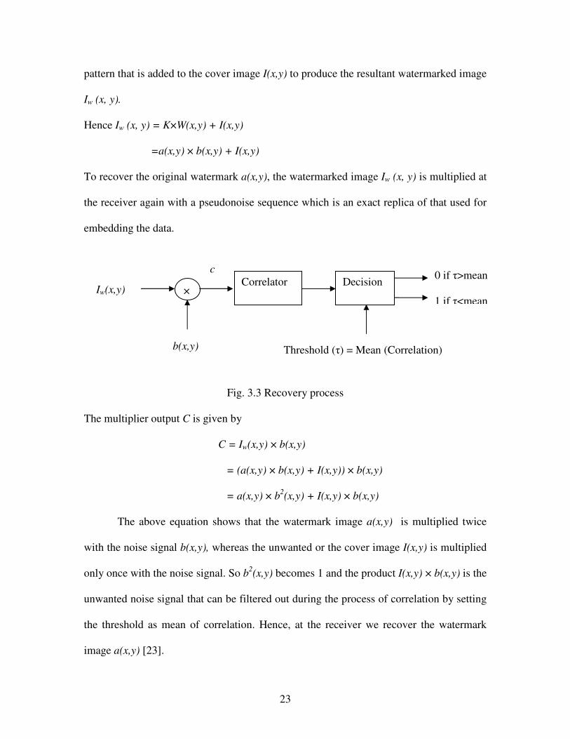
23
pattern that is added to the cover image I(x,y) to produce the resultant watermarked image
Iw (x, y).
Hence Iw (x, y) = K×W(x,y) + I(x,y)
=a(x,y) × b(x,y) + I(x,y)
To recover the original watermark a(x,y), the watermarked image Iw (x, y) is multiplied at
the receiver again with a pseudonoise sequence which is an exact replica of that used for
embedding the data.
Fig. 3.3 Recovery process
The multiplier output C is given by
C = Iw(x,y) × b(x,y)
= (a(x,y) × b(x,y) + I(x,y)) × b(x,y)
= a(x,y) × b2(x,y) + I(x,y) × b(x,y)
The above equation shows that the watermark image a(x,y) is multiplied twice
with the noise signal b(x,y), whereas the unwanted or the cover image I(x,y) is multiplied
only once with the noise signal. So b2(x,y) becomes 1 and the product I(x,y) × b(x,y) is the
unwanted noise signal that can be filtered out during the process of correlation by setting
the threshold as mean of correlation. Hence, at the receiver we recover the watermark
image a(x,y) [23].
Iw(x,y) ×
b(x,y)
Correlator Decision 0 if �>mean 1 if �<mean
Threshold (�) = Mean (Correlation)
c

24
The cover image used for the watermarking is a Lena 256 × 256, 8 bit gray scale,
bitmap image. The watermark used is a monochrome image of size 16 × 16. Key and the
gain are fixed before the generation of PN sequences. The watermark is then converted to
a string of zeroes and ones. A PN sequence of size equal to the original cover image is
generated for each of the pixel in the watermark vector. If the pixel in the watermark
vector is zero then the PN sequence with appropriate gain is added to the cover image
else zeroes are added. For retrieval of the watermark the PN sequences are generated with
the same key as used during the embedding process. The correlation is calculated
between the generated PN sequence matrix and the watermarked image for each of the
pixels in the watermark string and if it exceeds a particular threshold then the watermark
is said to be detected.
The robustness of the watermarked image increases as the gain K increases. But,
with the increase in the gain K, there is a reduction in the quality of the final watermarked
image. Therefore, there is a tradeoff between the robustness and the quality of the image.
PN sequences can be added to the cover image either by applying a random shift
or circular shift. A mathematical example for embedding and recovery of watermark is
shown below.
Example 1: This example illustrates the application of circular shift of one to the
generated PN sequence. Let I(x,y) be the cover object:
I(x,y) =
1 2 0 1 2 1 2 0 3 1 3 0 1 2 1 3

25
Watermark vector = (1 0 0 1)
Let a, b, c, d be the PN sequences generated for each of the elements in the
watermark vector 1, 0, 0 and 1.
a = b =
c = d =
Now, considering gain (k) = 2 we apply the formula Iw (x, y) = I (x, y) + k × W (x,
y). It is easy to observe that the sequences b and c are to be added to the original cover
object along with the appropriate gain factor because these are the sequences generated
for black pixels in the watermark vector.
Iw (x, y) =I(x,y)+(2×b)
Iw (x, y) =I(x,y)+(2×c)
0 1 1 1 1 0 0 0 1 1 0 1 0 0 1 0
0 0 1 1 1 1 0 0 0 1 1 0 1 0 0 1
1 0 0 1 1 1 1 0 0 0 1 1 0 1 0 0
0 1 0 0 1 1 1 1 0 0 0 1 1 0 1 0
1 2 2 3 4 3 2 0 3 3 5 0 3 2 1 5
3 2 2 5 6 5 4 0 3 3 7 2 3 4 1 5

26
This gives the resultant watermarked image after embedding the PN sequences for
each black pixel in the watermark vector. For recovery of the pixels the same PN
sequences are generated at the receiver and correlated with the watermarked image. The
threshold is set as the mean of the correlation value for all the pixels.
corr2 (Iw (x, y), a) = -0.2428
corr2 (Iw (x, y), b) = 0.5897
corr2 (Iw (x, y), c) = 0.5897
corr2 (Iw (x, y), d) = -0.3122
Average correlation or the threshold = 0.1561
So the pixels b and c are marked as black pixels and the pixels a and d are marked as the
white pixels for the recovery.
Example 2: This example illustrates the application of random shift to the
generated PN sequence. To show that both the methods of shifting the sequences work
we consider the same cover image and watermark vector.
I(x,y) =
Watermark vector = (1 0 0 1)
Let a, b, c, d be the PN sequences generated for each of the elements in the
watermark vector 1, 0, 0 and 1.
a = b =
1 2 0 1 2 1 2 0 3 1 3 0 1 2 1 3
0 1 1 1 1 0 0 0 1 1 0 1 0 0 1 0
0 0 0 1 0 1 1 0 1 1 1 1 0 0 1 0

27
c = d =
Now, considering gain (k) = 2 we apply the formula Iw (x, y) = I (x, y) + k × W (x,
y). From the above example we have to add PN sequences b and c multiplied with a gain
factor of 2 to the cover image
Iw (x, y) =I(x,y)+(2×b)
Iw (x, y) =I(x,y)+(2×c)
This gives the resultant watermarked image after embedding the PN sequences for
each black pixel in the watermark vector. For recovery of the pixels the same PN
sequences are generated at the receiver and correlated with the watermarked image. The
threshold is set as the mean of the correlation value for all the pixels.
corr2 (Iw (x, y), a) = -0.1041
corr2 (Iw (x, y), b) = 0.5897
corr2 (Iw (x, y), c) = 0.5897
0 1 0 0 1 1 1 1 0 1 1 0 1 0 0 0
0 1 0 0 1 0 1 1 0 0 0 1 1 1 1 0
1 2 0 3 2 3 4 0 5 3 5 2 1 2 3 3
1 4 0 3 4 5 6 2 5 5 7 2 3 2 3 3
28
corr2 (Iw (x, y), d) = -0.1041
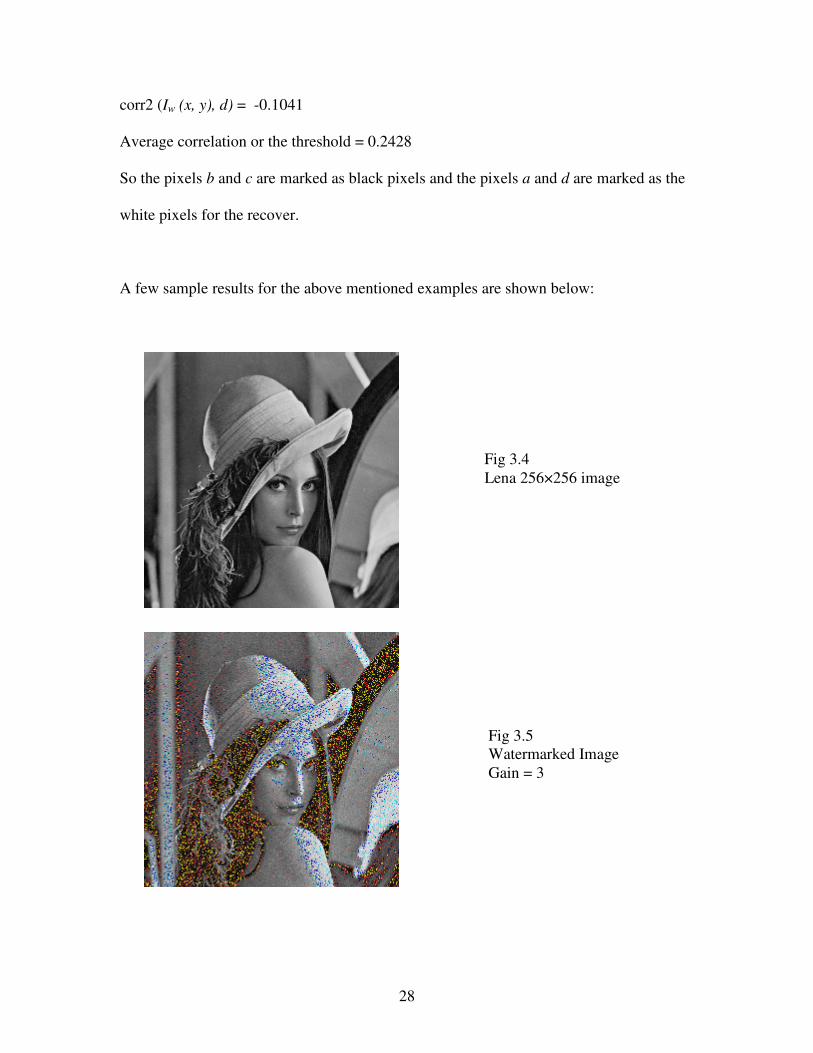
Average correlation or the threshold = 0.2428
So the pixels b and c are marked as black pixels and the pixels a and d are marked as the
white pixels for the recover.
A few sample results for the above mentioned examples are shown below:
Fig 3.5 Watermarked Image Gain = 3
Fig 3.4 Lena 256×256 image

29
Fig 3.6 Watermarked Image Gain = 5
Fig 3.7 Watermarked image Gain = 3 High pass filtered Lena Image
Fig 3.8 Original watermark 16 × 16 Monochrome image
Fig 3.9 Recovered watermark For gain = 3

30
3.4.2. Observations
Although watermarking using pseudonoise sequences is effective it has some
disadvantages associated with it. The sequence period is typically greater than the image
size and, therefore, the correlation at recovery is incomplete. This leads to a tradeoff
between the gain and the robustness of watermarked image. As the gain is increased from
3 to 5 in the Figures 3.5 and 3.6, the recovery of the watermark improves, but at the cost
of distorting the watermarked image. An improvement can be achieved by passing the
image through a high pass filter before applying the watermark, because reducing the
correlation between the cover image and the PN sequence increases the immunity to
noise. But this has an effect on the initial cover image, which loses its brightness and
appears dull. This is even more accentuated after the cover image is treated with the
watermark.
Fig 3.10 Recovered Watermark For gain = 5
Fig 3.11 Recovered watermark For Lena passed through High pass filter Gain = 3

31
Chapter 4 Watermarking Using Decimal Sequences
In this chapter, we introduce the technique of watermarking using decimal
sequences. Decimal sequences have better autocorrelation properties for some specific
shifts as compared to the pseudonoise sequences [16], so the results of watermark
recovery is expected to be better than the method using PN sequences.
4.1 Introduction
Decimal sequences are obtained when a number is represented in a decimal form
in a base r and they may terminate, repeat or be aperiodic. As these sequences are
periodic their randomness needs to be checked only in one period. For a certain class of
decimal sequences of 1/q, q prime, the digits spaced half a period apart add up to r-1,
where r is the base in which the sequence is expressed. These properties of decimal
sequences have made it possible to establish an upper bound on the autocorrelation
function. Decimal sequences are also known to have good cross correlation properties
and they can be used in applications involving PN sequences [16] [17]. In the following
sections we describe a few properties of decimal sequences, their generation using
feedback shift registers that allow carry and their application to watermarking.
4.2 Properties of Decimal Sequences
A few of the properties of the decimal sequences are stated in the form of
theorems from the well known results of number theory [17].
Any positive number x may be expressed as a decimal in the base r
A1A2………..As+1.a1a2……..

32
Where 0�Ai<r, 0�ai<r, not all A and a are zero, and an infinity of the ai less than (r-1).
There exists a one to one correspondence between the numbers and the decimals and
x = A1rs + A2rs-1 + …… + As+1 + a1/r + a2/r2
Decimal sequences of rational and irrational numbers may be possibly used to generate
pseudonoise sequences.
Theorem 1: A maximum length decimal sequence {1/q} when multiplied by p, p<q, is a
cyclic permutation of itself.
Definition: If q is a prime number, and r is a primitive root of q, then the decimal
sequence for 1/q is termed a maximal length decimal sequence in the base r. Maximal
length sequences may often be represented by the string of their first q-1 digits without
showing the decimal, or as {1/q}.
Proof: The remainders 1, 2, 3,…., q-1 obtained during the division of 1/q map into the
coefficients 0,1,2,……,r-1. Since, p/q starts off with a remainder rp (modulo q) instead of
r (modulo q), there would be a correspondence shift of decimal sequence.
Example: Consider x = {1/7}. The decimal sequence for x in base 10 is maximal length
because 102 � 1 (modulo7), 103
� 1 (modulo 7). Of course 106 � 1 (modulo 7).
The decimal sequence is 1 4 2 8 5 7, which corresponds to the remainder
sequence 3 2 6 4 5 1. The remainder sequence has a considerable structure. Thus, 3, 32,
33, 34, 35, 36 all computed modulo seven yields the successive digits of the sequence. If x
= {3/7} the remainder sequence starts with 30 � 2 (modulo 7) and is now 2 6 4 5 3 1, and
the decimal sequence for 3/7 is 4 2 8 5 7 1. This example suggests that the structure of
remainder sequence must also show up in the decimal sequence.

33
Theorem 2: If the decimal sequence in the base r of p/q; (p, q) = 1, p<q and (r, p) = 1 is
shifted to the left in a cyclic manner l times, the resulting sequence corresponds to the
number p’/q, (p’, q) = 1, p’<q where p’ � r’ x p (modulo q).
Theorem 3: For a maximal length decimal sequence {1/q} = a1a2a3……ak, k = q-1 in base
r:
ai + ak/2 + I = r – 1
Example: Take x = {1/17} in base r = 10
x = 0 5 8 8 2 3 5 2 9 4 1 1 7 6 4 7
Note that ai + a8 + I = r – 1 = 9.
Take x = {1/19} in base r = 2
x = 0 0 0 0 1 1 0 1 0 1 1 1 1 0 0 1 0 1
Here ai + a9 + I = r – 1 = 1.
The next theorem is and extension to the above theorem.
Theorem 4: If the period k of the decimal sequence of 1/q, where q is prime, is even in
the base r:
ai + ak/2 + I = r – 1.
Theorem 5: For a binary decimal sequence {1/q}, if 2m > q, then all li (m) are different.
For such a sequence, all subsequences of length m are different.
Theorem 6: The hamming distance dj between the binary maximal length sequence {1/q}
and its jth cyclic shift satisfies
dj � k/m, j � 0, j<k,
Where 2m > q, k = q-1.

34
From the above theorem, at least one of each m consecutive digits is going to be
different. Hence, the minimum distance between each set of m digits is one. For a total of
k such group of digits, the distance is k, and since the sequence considered is m times
over, the distance is k/m.
Autocorrelation Property: The autocorrelation property C1(j) of the binary maximum
length decimal sequence in the symmetric form (1, -1) satisfies C1(j) � 1 – 2/m, j � 0, j<k.
Since, a lower bound exists on the distance between a sequence and its cyclic shifts, these
sequences can be used for error detection and correction. A decimal (d) code for a
message expressed as integer u is defined as x = {u/q} where u � q – 1 and {1/q} is a
maximal length sequence.
Fig 4.1: Autocorrelation graph for q=293
Fig 4.1 is an autocorrelation plot for shifts ranging from 0 to 300 for prime
number q=293 which has a period 292. For good watermarking one must use shifts for

35
which autocorrelation value is zero. For shifts of the form n * (p/2) where n is an integer
and p is a period the absolute value of the autocorrelation values are very high and the
recovery of the watermark would be poor.
Cross Correlation Properties: Let C12(�) = (1/N) �i = 1,N ai bi + � represent the cross
correlation function of two maximal length sequences a1…..ak1 and b1…..bk2. The period
of the product sequence ai bi + � is N = lcm ( k1, k2), where lcm is the least common
multiple.
The cross correlation function of two maximal length decimal sequences in the
symmetric form is identically equal to zero if the ratio k1/k2 of their periods reduce to an
irreducible fraction n1/n2 where either n1 or n2 is an even number.
This property may be useful for the part of security against unauthorized detection
of the watermark by unauthorized users who don’t know the actual decimal sequence.
Fig. 4.2 Cross Correlation plots for q=5 with other primes

36
Fig 4.2 shows a plot for cross correlation of d-sequence (q = 5) with other primes
up to 2000 for zero shift. The highest value of cross correlation is observed at q = 5
whereas, for the other values of primes the cross correlation is close to zero.
4.3 Generation of Decimal Sequences
Decimal sequences can be generated by using feedback shift registers that allow
carry. The simplest way to generate a d–sequence is by using the equation ai = (2 i mod q)
mod 2.The hardware used for the generation of decimal sequences is similar to that used
for the m–sequences [18]. The algorithm used for the generation of decimal sequences is
called the Tirtha algorithm. Tirtha algorithm is used whenever the prime number q is
given in terms of the radix r as q = tr – 1, where t is an integer.
Theorem: Consider that 1/(tr – 1) defines the d–sequence a1a2a3….ak, where r is the radix
or the base. Consider another sequence u1u2u3….uk, where, for all i, ui < t, then
rui + ai = ui + 1 + tai +1
Proof: Since the sequences repeats itself ak = 1 and uk = 0. The remainder in the long
division of 1 by (tr – 1) is therefore t. The quotient ak-1 is given by
ak-1 (tr – 1) + t = mi – 1 r
This makes ak-1 = t, extending the argument the a and u sequences, when written in
inverse as
ukuk-1…..1
akak-1…...0
equal
0 0 …..1
1 t [t2]mod r……0
Example:

37
Consider {1/19} = 1/ (2 × (10 -1)) in the base 10. The inverse sequence is then given as
0 0 0 0 1 1 0 1 0 1 1 1 1 0 0 1 0 1
1 2 4 8 6 3 7 4 9 8 7 5 1 3 6 2 5 0
Or, the d–sequence for {1/19} is given by
0 5 2 6 3 1 5 7 8 9 4 7 3 6 8 4 2 1
The circuit for the generation of d–sequences 1/ (tr – 1) is given in figure 4.1.
It consists of n stages of shift registers. The c’s represent carries that are added to
the immediately preceding stages. When the carry is generated by the extreme left stage,
it is introduced into this stage at the very next clock instant. The sequence generated will
be in the inverse order. The same principle can be used to generate binary d–sequence.
The number of stages needed for the generation of binary d–sequence 1/q is about log2 q.
The algorithm also works for the non binary sequences of the type 1/(tr – 1) when the
given fraction is multiplied by an appropriate integer so that the standard form can be
used.
Fig 4.3 Generation of d-sequences
tn-2 tn-1 t0 t1
C C C C C
Output

38
Although we use all binary d–sequences for watermarking, other types of d–sequences
called the generalized d–sequences can also be used.
If q is a prime number and r is the base of the sequence, then the generalized d–
sequences are generated according to the equation [19]
q mod r � -k � -1/l
ai = l[ri mod q] mod r
The generalized d–sequences are categorized into two types based on their
definition [20]:
Type 1: The expansion of {1/q} in base r (non binary) in this case is given by:
ai = [ri mod q] mod r
where, q is the prime number and r is the base.
Example: Consider q = 17 and the base r = 5, {1/17} base 5
The sequence ai = [3i mod 11] mod 3
= [3 9 5 4 1] mod 3
= [0 0 2 1 1]
Since the base is 3 the digits in the sequence are 0, 1 and 2 and the period of the sequence
is 5 after which the digits repeat.
Type 2: This is the case in which the expansion of {1/q} in base r is given by
ai = [ri mod q] mod s
where, r is a non-binary base and s = 3.
Example: Consider the sequence of {1/13} base 7.
ai = [7i mod 13] mod 3
= [7 10 5 9 11 12 6 3 8 4 2 1] mod 3

39
= [1 1 2 0 2 0 0 0 2 1 2 1]
4.4 Watermarking Using Decimal Sequences
We have noted earlier that PN sequences based watermarking produces noise due
to high autocorrelation values as the period of generated PN sequences is too large when
compared to the size of the cover image. To improve the recovery in certain cases the
original cover image needs to be high pass filtered but this affects the quality of the
watermarking. Since d-sequences have zero cross correlation for some prime numbers
[16], one would obtain superior performance if different d-sequences are used in the
watermark. But, if the same d-sequence is used, the autocorrelation can be as high as 33%
during certain shifts of the sequence, but since many other shifts have zero
autocorrelation, we can selectively use these shifts to produce better results [21]. The use
of decimals sequences also gives the flexibility of trying out various prime numbers until
we get satisfactory embedding and recovery of the hidden information.
4.4.1 Embedding and Recovery Using Decimal Sequences
A decimal sequence is generated in Matlab using the function
dseq = [ri mod q] mod r
Where, r is the radix or the base and q is the prime number.
The addition of the d–sequences to the cover image is done in a manner similar to
that applied for the PN sequences as discussed in chapter 3.
There is a trade off between the robustness and the quality of the image as the
gain K is increased. But, the decimal sequences gives us an option of experimenting with
various prime numbers, keeping the gain constant, until we observe a satisfactory result
for both encryption of data and its retrieval. For retrieval of the encrypted message the
decimal sequences are generated again and then correlated with the watermarked image.

40
The d-sequences may be added to the cover image by either a circular shift or a random
shift.
Sample results for random shifts as defined above are shown below:
Fig 4.4 256 × 256 (8 bit) Gray scale Lena image
Fig 4.5 8 × 8 Watermark object Monochrome Image
Fig 4.6 Embedding output, q = 283
Fig 4.7 Decoding output, Period = 94

41
Fig 4.8 Embedding output, q = 167
Fig 4.9 Decoding output, Period = 84
Fig 4.10 Embedding output, q = 263
Fig 4.11 Decoding output, Period = 131

42
Fig 4.12 Embedding output, q = 293
Fig 4.13 Decoding output, Period = 292
Fig 4.15 Decoding output, Period = 939
Fig 4.14 Embedding output, q = 1879

43
Sample results for circular shifts
Fig 4.16 Watermarked image, q=293 Fig 4.17 Retrieved Watermark Period = 292 Circular shift = 50
Fig 4.18 Watermarked Image Fig 4.19 Retrieved Watermark Period = 292 Circular Shift = 146
44
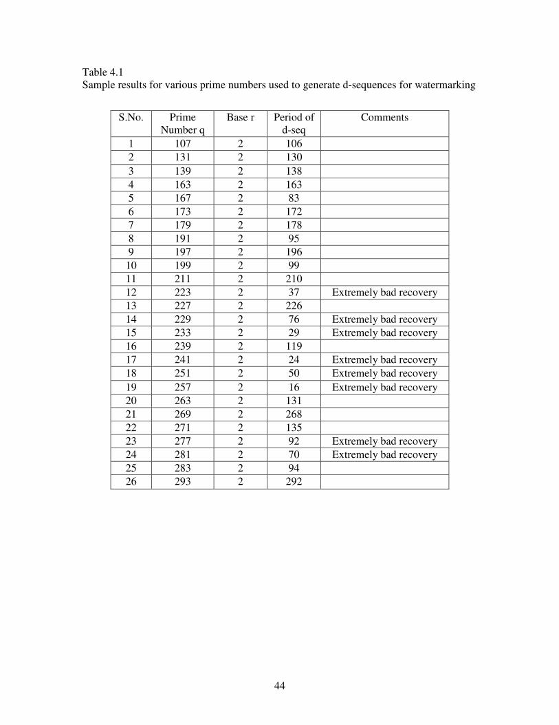
Table 4.1 Sample results for various prime numbers used to generate d-sequences for watermarking
S.No. Prime Number q
Base r Period of d-seq
Comments
1 107 2 106 2 131 2 130 3 139 2 138 4 163 2 163 5 167 2 83 6 173 2 172 7 179 2 178 8 191 2 95 9 197 2 196
10 199 2 99 11 211 2 210 12 223 2 37 Extremely bad recovery 13 227 2 226 14 229 2 76 Extremely bad recovery 15 233 2 29 Extremely bad recovery 16 239 2 119 17 241 2 24 Extremely bad recovery 18 251 2 50 Extremely bad recovery 19 257 2 16 Extremely bad recovery 20 263 2 131 21 269 2 268 22 271 2 135 23 277 2 92 Extremely bad recovery 24 281 2 70 Extremely bad recovery 25 283 2 94 26 293 2 292

45
Chapter 5
Analysis of Results
In this chapter, we analyse the results of watermarking obtained as in Figures 4.5
to 4.19 and Table 4.1.
5.1 Performance Analysis
To analyse the performance of decimal sequences for watermarking we first consider
some extremely bad recovery cases.
Example 1:
For q = 277 with r = 2
From Fig 5.2 it is evident that the recovered watermark is dominated by noise.
The increase in the number of noise pixels is due to the decrease in the period of decimal
sequence.
Fig 5.1 Embedding output, q = 277
Fig 5.2 Decoding output, Period = 92

46
Fig 5.3 Autocorrelation for q=277
From Fig 5.3 it is evident that for autocorrelation values lying between the
standard deviation range good recovery is possible while for autocorrelation values lying
very close to the mean the best possible recovery is obtained. The best possible recovery
need not necessarily be the original watermark image because it is also a function of the
period of the d-sequence.
Example 2:
q = 257 with r = 2
This is a case for which the period is extremely small.

47
Fig 5.6 Autocorrelation for q=257
From the Fig 5.6 above it is found that the period of the generated decimal
sequence for this example is 16 i.e. (q-1)/16. The recovered watermark for such a small
Fig 5.4 Embedding output, q = 257
Fig 5.5 Decoding output, Period = 16

48
period is seen to be filled with all noise pixels and a total black box of size equal to the
actual watermark is obtained at recovery. If the period of the d-sequence is such that, the
square of the period is equal to the used prime number then the noise in the watermarked
image is vertically distributed, equally throughout the image.
As the period for the generated decimal sequence decreases, the amount of noise
pixels in the recovered watermark increases. This is directly related to the reduction in
randomness of the sequence with a decrease in period and also to the high autocorrelation
values.
5.2 Correlation Analysis In this section, we display some graphs showing the distribution of the pixels of
watermark around the mean correlation value. The noise associated with the retrieval of
watermark is due to the fact that some pixels have correlation values very close to the
mean correlation which is set as the threshold. In that instance, the retrieval algorithm
takes it as a black pixel which results as a noise pixel in the recovery. On the other hand,
a perfect recovery has exactly the number of black pixels in the watermark above the
threshold.
Figure 5.7 shows a correlation graph for watermarking using the prime number q
= 293 that has a period of 292 or (q-1). The watermark used has 19 black pixels and rest
white. The results of embedding and recovery are shown in Figure 4.12 and 4.13 in
chapter 4. We observe that there are no noise pixels associated with the recovery of the
watermark in Figure 4.11. The mean correlation set as threshold for recovery of
watermark was calculated and found as 0.0057. It is evident that there are no pixels
scattered around this value and exactly 19 pixels have their correlation values above the

49
threshold. Hence, these are the only black pixels in the recovery and the recovery is noise
free.
Fig 5.7 Correlation graph for q = 293
Fig 5.8 shows a correlation graph for the recovery for q = 277, where the period
of the sequence is 92 or (q-1)/4. The recovered watermark as seen in Figure 5.2 is all
filled with noise pixels and cannot be clearly identified. The watermark in this case is
same as used for all other cases with 19 black pixels. But, the bad recovery is due to the
reason that the correlation value calculated exceeds the mean correlation for 31 pixels
instead of 19 pixels. The other pixels are all distributed randomly as noise in the
recovered watermark. This can be attributed to the small period of the decimal sequence.
The mean correlation in this case was found to be as 0.0240.

50
Fig 5.8 Correlation graph for q = 277
Figure 5.9 Correlation graph for q = 257

51
The graph in Figure 5.9 is for prime number q=257 that generates a sequence with
a period of 16 or (q-1)/16. The recovered watermark is a complete black patch that
displays all the pixels in the watermark to be black. The mean correlation in this case is
found as 0.4946 and all the pixels have a correlation value of 0.5 which is greater that the
mean correlation. Therefore, all the pixels are considered as black and the recovery is all
black values.
The above graphs indicate that as the period of the generated decimal sequence
reduces, the noise associated with the recovery increases. This is in turn associated with
reduced randomness of the sequence with reduction in period. This causes a possible
increase in the correlation value for pixels and thus causes more noise at the output.
5.3 Observations
Table 5.1 shows results of some simulations carried out for different prime
numbers ranging from 100 to 25000. The main aim of this table is to help define a range
for the mean and standard deviation across the mean for good and successful recovery of
the hidden message. A similar table was shown in chapter 4 to display good and bad
recovery of watermark associated with the period of generated decimal sequence.
Table 5.1 Mean and Standard deviation analysis table for 256 × 256 Lena image
Prime Number Period Mean Std. Deviation Recovery
107 106 (q-1) 0.0096 0.0107 Good
131 130 (q-1) 0.0195 0.0089 OK(2)
139 138 (q-1) 0.0065 0.0119 Ok (3)
167 83 (q-1)/2 0.0003 0.0108 Good(1)
(Table Continued…..)

52
173 172 (q-1) 0.0045 0.0104 Good(1)
179 178 (q-1) 0.0111 0.0097 OK(3)
191 95 (q-1)/2 0.0013 0.0091 Good
197 196 (q-1) 0.0015 0.0100 Good
199 99 (q-1)/2 0.0015 0.0110 Good(2)
211 210 (q-1) 0.0040 0.0094 Good
223 37 (q-1)/6 0.0003 0.0122 Very Bad
227 226 (q-1) 0.0080 0.0095 Good
229 76 (q-1)/3 0.0258 0.0119 Very Bad
233 29 (q-1)/8 0.0268 0.0117 Very Bad
239 119 (q-1)/2 0.0034 0.0096 Good
241 24 (q-1)/10 0.1200 0.0091 Very Bad
251 50 (q-1)/5 0.0452 0.0110 Very Bad
257 16 (q-1)/16 0.4946 0 Worst
263 131 (q-1)/2 0.0008 0.0092 Very Good
269 268 (q-1) 0.0057 0.0080 Noise (Ok)
271 135 (q-1)/2 0.0052 0.0091 Perfect
277 92 (q-1)/4 0.0163 0.0139 Bad
281 70 (q-1)/4 0.0037 0.0153 Bad
283 94 (q-1)/3 0.0003 0.0141 Noise(OK)
(Table Continued………)

53
293 292 (q-1) 0.0038 0.0100 Perfect
1987 1986 (q-1) 0.0047 0.0090 Perfect
1879 939 (q-1)/2 0.0042 0.0097 Good
5953 992 (q-1)/6 0.0093 0.0129 Very Bad
7393 264 (q-1)/28 0.0039 0.0114 Very Bad
7451 7450 (q-1) 0.0054 0.0092 Good
14449 84 (q-1)/172 0.0039 0.0182 Very Bad
14923 14922(q-1) 0.0054 0.0090 Good(1)
24841 6210 (q-1)/4 0.0057 0.0093 Good(3)
24989 24988 (q-1) 0.0057 0.0090 Good(1)
Some important observations
• The mean correlation should be small for good recovery. But this is not the only
criterion for a good recovery.
• The standard deviation was found to be in the range of 0.080 to 0.0110 for good
recovery of watermark. As the standard deviation increased above this limit, more
number of pixels fell in the range near the mean thereby increasing noise. As a
special case for q = 257 where the standard deviation is 0 we get a black box as
recovered watermark. This is due to the reason that all the pixels have correlation
values equal to the mean correlation.
• Very small mean correlation and very large standard deviation would not result in
good recovery and large mean and large standard deviation would also not result
in good recovery.

54
• All different black and white images will have different ranges for standard
deviation for good recovery as the grey scale varies from image to image.

55
Chapter 6
Conclusions
This thesis presents techniques of watermarking using decimal sequences. These
sequences have zero autocorrelation for certain shifts which could be useful in the
recovery of watermarks by using spread spectrum techniques. Use of these sequences
over PN sequences provides the following advantages:
• Hardware complexity can be reduced by not incorporating the high pass filter
which might be needed in case of PN sequences when the recovery is not optimal.
• Performance of the d-sequence watermarking can be improved by using a variety
of prime numbers with varied periods and particular shifts that provide close to
zero autocorrelations.
• Decimal sequences exhibit zero cross correlation for some prime numbers and
near to zero cross correlation for others, which would be useful if different d-
sequences are used in the watermark.
• There is a trade off between robustness and perceptibility of the watermarked
image as the gain K is increased for both d–sequences and the PN sequences but,
for d–sequences we can use a different prime number with varied periods rather
than accepting reduced performance.
This thesis is limited to watermarking of still black and white. Further research
can be done for developing watermarking techniques for audio and video images,
network packets, software and circuitry.

56
Bibliography
1. Katzenbeisser, S., Petitcolas, F.A.P., Information hiding techniques for steganography and digital watermarking, Artech House Publishers, 2000.
2. Gnanaguruparan, M., “Recursive secret sharing in visual cryptography”, MS
thesis, Louisiana State University.
3. www.iusmentis.com/technology/encryption
4. www.pgi.org/doc/pgintro
5. Shoemaker, C., “Hidden bits: A survey of techniques for digital watermarking”, Independent study, EER 290, spring 2002.
6. Johnson, N.F., Jajodia, S., and Duric, Z., Information hiding: Steganography and
watermarking attacks and countermeasures, Kluwer academic Publishers, 2000.
7. Wang, Y., Doherty, J.F., and Van Dyck, R.E., “A watermarking algorithm for fingerprinting Intelligence images”, Conference on Information Science and Systems, The John Hopkins University, March 21-23, 2001.
8. Kutter, M., and Hartung, F., Introduction to watermarking techniques –
Information technology for steganography and digital watermarking, Artec House, 2000.
9. Cox, I.J., Miller, M.L., and Bloom, J.A., “Watermark application and their
properties” International Conference on Information Technology, Las Vegas, 2000.
10. Carlson, A.B., Crilly, P.B., and Rutledge, J.C., Communication Systems.
11. http://cpk.auc.dk/dicom/Eo2/CDMA.htm
12. Swatson, M.D., Jhu, B., and Tewfik, A.H., “Transparent robust image watermarking”, Department of Electrical engineering, University of Minnesota.
13. http://www.cs.unt.edu/~rakl/class4330/CHAP7.pdf
14. Voigt, Z., “Watermarking 2D vector data for Geographical Information Systems”, proceedings of SPIE, Security of Watermarking and Multimedia Content, San Jose, 2002.
15. Herlekar, S., and Kak, S.C., “Performance analysis of a d-sequence based Direct
Sequence CDMA system”, LSU report, 2002.

57
16. Kak, S.C., and Chatterjee, A., “On Decimal Sequences”, IEEE Transactions on Information Theory, vol. IT-27, No.5, pp. 647 – 652, 1981.
17. Kak, S.C., “Generating d–sequences”, Electronics Letters, vol. 23, pp. 202-203,
1987. 18. Kak, S.C., “New results on d–sequences”, Electronics Letters, vol. 23, No. 12, pp.
617, 1987. 19. Vaddiraja, R., “Generalized d–Sequences and their Applications to CDMA
Systems”, MS Thesis, Louisiana State University, 2003. 20. Kak, S.C., “Encryption and Error–Correction Coding Using d–Sequences,” IEEE
Transactions and Computers, vol. C-34, pp. 803-809, 1985.
21. Kahn, D., The Codebreakers, 2nd edition. New York: Macmillan, 1996.
22. Clelland C.T., Risca, V., Bancroft, V., Hiding messages in DNA microdots. Nature, vol. 399, pp. 533-534, 1999.
23. Haykin, S., Communication Systems, 4th edition, John Wiley and Sons, Inc, 2001.

58
Vita Navneet Kumar Mandhani was born in the town of Vizianagaram in India. He grew up in
the city of Madras, the capital city of the state Tamil Nadu. He graduated from high
school in the year 1998. In fall of 1998, he joined the Gandhi Institute of Technology and
Management (GITAM) at the steel city Visakhapatnam and obtained his Bachelor of
Engineering degree in the department of Electronics and Communications engineering in
spring 2002.
He joined Louisiana State University in the fall of year 2002 and is set to obtain his
degree of Master of Science in the department of Electrical Engineering in August 2004.