waterp water enhanced resource planning · the pim registers the pilots’ sensors in the sos...
TRANSCRIPT
WatERP
Water Enhanced Resource Planning
“Where water supply meets demand”
GA number: 318603
WP 7: Pilots
7.3.2: Implementation of the Water Data Warehouse (WDW)
V1.0 11/03/2015
www.waterp-fp7.eu
Ref. Ares(2015)1494710 - 07/04/2015

Ref. 318603 - WatERP D7.3.2_Implementation_of_WDW_v1.0 page 2 of 24
Document Information
Project Number 318603 Acronym WatERP
Full title Water Enhanced Resource Planning “Where water supply meets demand”
Project URL http://www.waterp-fp7.eu
Project officer Grazyna Wojcieszko
Deliverable Number 7.3.2 Title Implementation of the Water Data Warehouse (WDW)
Work Package Number 7 Title Pilots
Date of delivery Contractual M28 Actual M30
Nature Prototype Report X Dissemination Other
Dissemination
Level Public X Consortium
Responsible Author Johannes Kutterer Email [email protected]
Partner DISY Phone (+49) 721 1 6006-286
Abstract
(for dissemination)
Implementation of the Water Data Warehouse (WDW): This Task is implementing the central
database of the WatERP platform in the two pilot areas. The main activity in this task is to put
together the methods, reference data models and tools developed in WP3, to apply them to the
particularities of the two pilot areas, and to deploy them for the pilot users ACA and SWKA. Then,
the deployed technologies are thoroughly tested and examined with real-world data and usage
conditions.
Key words Water Data Warehouse (WDW), Pilot Integration Manager (PIM), WaterML2.0, SOS, software
integration, pilot implementation

Ref. 318603 - WatERP D7.3.2_Implementation_of_WDW_v1.0 page 3 of 24
Glossary of acronyms
ACA Agencia Catalana del Agua (trans.
Catalan Water Agency)
CUAHSI Consortium of the Universities for the
Advancement of Hydrological Science
Inc.
DMS Demand Management System
DRL Data Retrieval Language
DSS Decision Support System
DMZ Demilitarized Zone
HIS Hydrologic Information System
Hydro DWG Hydrology Domain Working Group
OWL Web Ontology Language
MAS Multi Agent System
O&M Observations and Measurements
ODM Observation Data Model
OGC Open Geospatial Consortium
OMP Open Management Platform
OWL Web Ontology Language
PIM Pilot Integration Manager
REST Representational State Transfer
SOS Sensor Observation Service
SensorML Sensor Markup Language
SWE Sensor Web Enablement
SWKA Stadtwerke Karlsruhe
WaterML Water Markup Language
WDTF Water Data Transfer Format
WDW Water Data Warehouse
XML Extensible Markup Language

Ref. 318603 - WatERP D7.3.2_Implementation_of_WDW_v1.0 page 4 of 24
Executive Summary
This document describes the activities to implement the WDW on the pilot site. It describes what sensor
observation data is currently stored on the pilot site and how this data is accessed and imported into the
WDW.
To fully understand this document, the following deliverables have to be read.
Number Title Description
D1.3 Generic Ontology for water
supply distribution chain
This deliverable summarizes the ontology including the scope, purpose and
implementation language to be used.
D1.4.1 Inference and Simulation
Engine Conceptual Design
This deliverable depicts the architecture of the Decision Support System
including a behavioural definition of the inference and simulation engine.
D2.1 External System Integration
requirement
Comprehensive review of generic water supply - distribution chain was
undertaken in order to understand general requirement for system
integration and interoperability to be performed within the WatERP project
development.
D3.1 WDW Conceptual Design
Report summarizing architectural design of the water data warehouse used
to integrate all data relevant for the WatERP project and the interfaces used
for data integration.
D3.2 WDW 1st Prototype
Description of the implementation, installation and usage of the Water Data
Warehouse.
D3.3 WDW 2nd
Prototype Description of the implementation, installation and usage of the Water Data
Warehouse.
D7.3.1
Implementation of the
Water Data Warehouse
(WDW)
Description of the implemention of the WDW on the pilot site.
Ref. 318603 - WatERP D7.3.2_Implementation_of_WDW_v1.0 page 5 of 24
Table of contents
WATERP ................................................................................................................................................... 1
WATER ENHANCED RESOURCE PLANNING ...................................................................................... 1
“WHERE WATER SUPPLY MEETS DEMAND” ..................................................................................... 1
GA NUMBER: 318603 .............................................................................................................................. 1
WP 7: PILOTS ........................................................................................................................................... 1
7.3.2: IMPLEMENTATION OF THE WATER DATA WAREHOUSE (WDW) .......................................... 1
DOCUMENT INFORMATION ................................................................................................................... 2
GLOSSARY OF ACRONYMS .................................................................................................................. 3
EXECUTIVE SUMMARY .......................................................................................................................... 4
TABLE OF CONTENTS ............................................................................................................................ 5
TABLE OF FIGURES................................................................................................................................ 7
1. INTRODUCTION ............................................................................................................................... 8
1.1 WATERP OVERVIEW.................................................................................................................................... 8
FIGURE 1 "WATERP ARCHITECTURE FROM THE INTEGRATION POINT OF VIEW" ...................... 9
1.2 STANDARDS FOR INFORMATION INTERCHANGE ................................................................................................ 9
1.3 SCOPE OF CONSOLIDATION AND INSTALLATION PHASE ..................................................................................... 9
2. BASIC CONCEPTS ........................................................................................................................ 11
FIGURE 2 "INTEGRATION OF EXISTING PILOT INFRASTRUCTURE" ............................................. 11
FIGURE 3 "PILOT SITE ACCESS BY THE WDW AND FURTHER PROCESSING" ........................... 12
3. ACA SITE INTEGRATION .............................................................................................................. 13
FIGURE 5 “CURRENT INSTALLATION SCENARIO FOR ACA" ......................................................... 13
3.1 DATA STATISTICS ...................................................................................................................................... 14
4. SWKA SITE INTEGRATION ........................................................................................................... 15
4.1 EXISTING DATA INFRASTRUCTURE ................................................................................................................ 15
4.2 SWKA PILOT INTEGRATION MANAGER ........................................................................................................ 16
4.2.1 Data Access ....................................................................................................................................... 16
4.2.2 Data Mapping ..................................................................................................................................... 17

Ref. 318603 - WatERP D7.3.2_Implementation_of_WDW_v1.0 page 6 of 24
FIGURE 10 "FLOW CHART OF CLIENT APPLICATION" .................................................................. 18
4.2.3 Data Export ........................................................................................................................................ 18
4.3 DATA STATISTICS ...................................................................................................................................... 18
4.4 NEXT STEPS ............................................................................................................................................. 19
5. PERFORMANCE ............................................................................................................................ 20
5.1 CANDIDATES FOR PERFORMANCE TESTING ................................................................................................... 21
5.2 PERFORMANCE ACA ................................................................................................................................. 22
5.3 PERFORMANCE SWKA .............................................................................................................................. 23
6. CONCLUSIONS AND FUTURE WORK ......................................................................................... 24
Ref. 318603 - WatERP D7.3.2_Implementation_of_WDW_v1.0 page 7 of 24
Table of figures
FIGURE 1 "WATERP ARCHITECTURE FROM THE INTEGRATION POINT OF VIEW" .................................................................... 9
FIGURE 2 "INTEGRATION OF EXISTING PILOT INFRASTRUCTURE" ....................................................................................... 11
FIGURE 3 "PILOT SITE ACCESS BY THE WDW AND FURTHER PROCESSING" ..................................................................... 12
FIGURE 4: "ACA SENSOR DATA IN EXCEL FILE " ............................................................................................................ 13
FIGURE 5 “CURRENT INSTALLATION SCENARIO FOR ACA"............................................................................................... 13
FIGURE 6 "DATABASE TABLE FROM PILOT SITE SWKA" ................................................................................................... 15
FIGURE 7 "SWKA PUMP DATA IN ORACLE" .................................................................................................................... 15
FIGURE 8 “EXCEL FILE FOR SWKA SENSOR INFORMATION” ............................................................................................ 16
FIGURE 9 “EXCEL FILE FOR SWKA LOCATION INFORMATION” .......................................................................................... 16
FIGURE 10 "FLOW CHART OF CLIENT APPLICATION" ...................................................................................................... 18
FIGURE 11 "CURRENT INSTALLATION SCENARIO FOR SWKA" ......................................................................................... 19
FIGURE 12 RESPONSE TIMES OF THE SOS SERVER OVER DATASET SIZE ........................................................................... 20
FIGURE 13 COMPARISON OF RESPONSE TIMES OVER DATASET SIZE .................................................................................. 21
FIGURE 14 FLOW CHART OF THE PIM AND WDW COMPONENTS WORKING TOGETHER. THE CANDIDATES FOR PERFORMANCE
TESTING ARE MARKED AS DASHED AND DOTTED ARROWS. ....................................................................................... 22

Ref. 318603 - WatERP D7.3.2_Implementation_of_WDW_v1.0 page 8 of 24
1. Introduction
This document describes the activities to implement the Water Data Warehouse (WDW) in the two pilot
sites. It shows what actions have been taken and which tools had to be implemented in order to
integrate and make use of the existing data structures. The technical descriptions of tools that were
implemented can be found in more depth in D3.3-“WDW 2nd
Prototype” and in D3.4 “WDW Final
Prototype” which is scheduled for delivery on month 30.
This document will first give a very brief overview over the WatERP systems and will explain how pilots
are integrated from the architectural point of view. Next, the document gives a detailed description of
each pilot’s data infrastructure and what strategy has been implemented to tie the client to the WDW
platform. Finally, the document will summarize the state that has been reached so far and explain the
future steps that still have to be taken.
1.1 WatERP overview
As also described in D3.2-“WDW 1st Prototype” and D3.3-“WDW 2nd
Prototype” the WDW is the central
component of the WatERP software and data infrastructure. Its main function is to work as a reliable
and durable data basis for all other components, providing both data needed for analyses or other
functions as well as automated routines to incorporate new data sources and datasets at any given
time. The content is available for the analysis clients via the Multi Agent System (MAS). The WDW
provides ontology information, semantically derivable inferences, as well as observation results.
Figure 1 gives an overview over the different layers of the WatERP architecture and, especially, shows
how the layers interact. A more detailed description of the WatERP architecture can be found in D2.3-
“Open Interface Specification” chapter 3 “WatERP architecture”.
The integration of the pilot data is realized via an SOS server that contains both ontology metadata and
observation results.

Ref. 318603 - WatERP D7.3.2_Implementation_of_WDW_v1.0 page 9 of 24
Figure 1 "WatERP architecture from the integration point of view"
1.2 Standards for information interchange
As it was decided in the D2.1-“External systems” chapter 5, all exchange of observation data is based
on WaterML2 time series. This standard provides an XML based combination of ontology and
observation results. For the pilot integration this means that the sensor data has to be transformed into
WaterML2 and stored into an SOS server that is accessed from the WDW to import the time series.
This way the WDW has only to deal with a single data format when it accesses the pilot infrastructure.
Every transformation and mapping has to be accomplished by the Pilot Integration Manager (PIM)
which is implemented depending on the pilots’ needs.
1.3 Scope of consolidation and installation phase
Whereas the first phase was focused on proof-of-concept and a first vertical integration of the PIM and
WDW, the second phase focused on the consolidation of the concepts and tools and the testing of the
complete setting of PIM and WDW. The integration of all components was tested by an installation on a
preproduction server. This deliverable covers consolidaton and further development of each pilot.
WDW
SOS server
SOS client
On
tolo
gy
MAS
DSS
OGC WPS server
DMS
OGC WPS server
Hydrological forecast
OGC WPS server
SWKA Pilot
OGC SOS Server
ACA Pilot
OGC SOS Server
WatERP Framework
Pilot Data integration
Building Block Integration
OMP
WaterML2
WaterML2, OWL, drl WaterML2, OWL WaterML2

Ref. 318603 - WatERP D7.3.2_Implementation_of_WDW_v1.0 page 10 of 24
Further it disscuses and highlighs changes in the concept that has been reworked from the first
integration phase.

Ref. 318603 - WatERP D7.3.2_Implementation_of_WDW_v1.0 page 11 of 24
2. Basic Concepts
Section 2 of WatERP deliverable D7.3.1 presented the concepts and tools required for installing the
WDW software infrastructure in a pilot site.
There, the role of the Pilot Integration Module (PIM) that transports data from the pilot’s sensor
infrastructure and legacy databases to the WDW server through the SOS communication protocol using
the WaterML2 data model was described.
Figure 2 "Integration of existing pilot infrastructure"
Then, at the two pilot sites, the following preparatory tasks had to be performed:
(1) Data access – which is about getting access to the operational data without compromising
security, stability and efficiency of the existing operational systems.
(2) Data Mapping – which is about transforming the data formats in use internally in the pilot’s
existing systems into the OGC SOS WaterML2 format, and registering the required SOS
sensor.
(3) Data Import – which is about importing concrete data from the pilots’ existing systems and
about moving them to the SOS server.
After these preparatory steps, the following concrete activities are performed in order to access the pilot
site, transfer data and process the WaterML2 documents (see Figure 3):
1. The PIM registers the pilots’ sensors in the SOS server and adds the observations.
2. The sensors registered in the SOS server are also registered in the WDW.
3. The WDW polls the SOS server for new observation results and stores the observations in the
WDW SOS server.
4. The SOS data is also used to populate the entities in the triple store.

Ref. 318603 - WatERP D7.3.2_Implementation_of_WDW_v1.0 page 12 of 24
Figure 3 "Pilot Site Access by the WDW and Further Processing"
More details on the technical realization of these steps have been given in deliverable D7.3.1.

Ref. 318603 - WatERP D7.3.2_Implementation_of_WDW_v1.0 page 13 of 24
3. ACA site integration
In deliverable D7.3.1, it has already been shown:
- How the WaterOneFlow format previously used in ACA has been mapped to WaterML2.
- Which formats are provided by ACA’s WaterOneFlow Web Service interface.
- How the ACA Pilot Integration Manager is configured.
After realizing these first steps of pilot integration, the conversion from WaterOneFlow to WaterML2 had
to be adjusted. For each variable there had to be created a mapping to the matching offering and
observed property.
ACA has introduced an Excel sheet with information about the sensors. A snapshot of this Excel sheet
is shown in the Figure 4. This file contains all the required information to fill the ACA database and there
is no more need to extract the variables of site and variable combinations from the WaterOneFlow Web
service. Next step is to fill the PostgreSQL database for ACA with this Excel file as it is done for SWKA.
Figure 4: "ACA Sensor Data in Excel File "
The polling start time, which defines the extent of historical data available in the WDW, must be set
according to the requirements of the analysis. After installation of the ACA pilot integration module and
the pilot SOS server, the system will start to poll and fill the SOS database.
Then ACA will be prepared to be integrated into the WDW for further analysis. As the WaterOneFlow is
already available externally, a first integration in WatERP is possible without any installations on the
pilot site. Figure 5 shows the current installation scenario.
Figure 5 “Current Installation Scenario for ACA"
Ref. 318603 - WatERP D7.3.2_Implementation_of_WDW_v1.0 page 14 of 24
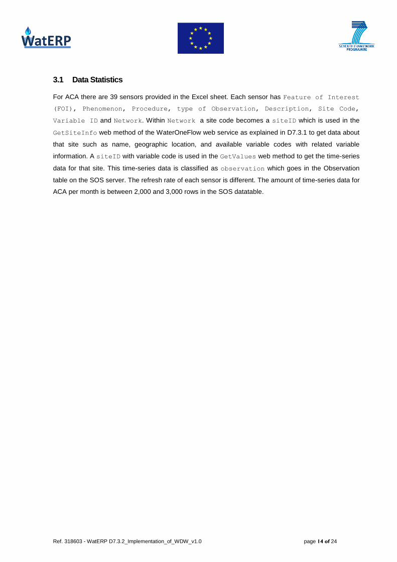
3.1 Data Statistics
For ACA there are 39 sensors provided in the Excel sheet. Each sensor has Feature of Interest
(FOI), Phenomenon, Procedure, type of Observation, Description, Site Code,
Variable ID and Network. Within Network a site code becomes a siteID which is used in the
GetSiteInfo web method of the WaterOneFlow web service as explained in D7.3.1 to get data about
that site such as name, geographic location, and available variable codes with related variable
information. A siteID with variable code is used in the GetValues web method to get the time-series
data for that site. This time-series data is classified as observation which goes in the Observation
table on the SOS server. The refresh rate of each sensor is different. The amount of time-series data for
ACA per month is between 2,000 and 3,000 rows in the SOS datatable.
Ref. 318603 - WatERP D7.3.2_Implementation_of_WDW_v1.0 page 15 of 24
4. SWKA site integration
4.1 Existing data infrastructure
In deliverable D7.3.1, the existing data infrastructure at SWKA, which basically consists of a data
warehouse where all the sensor-network results are fed into, was already discussed.
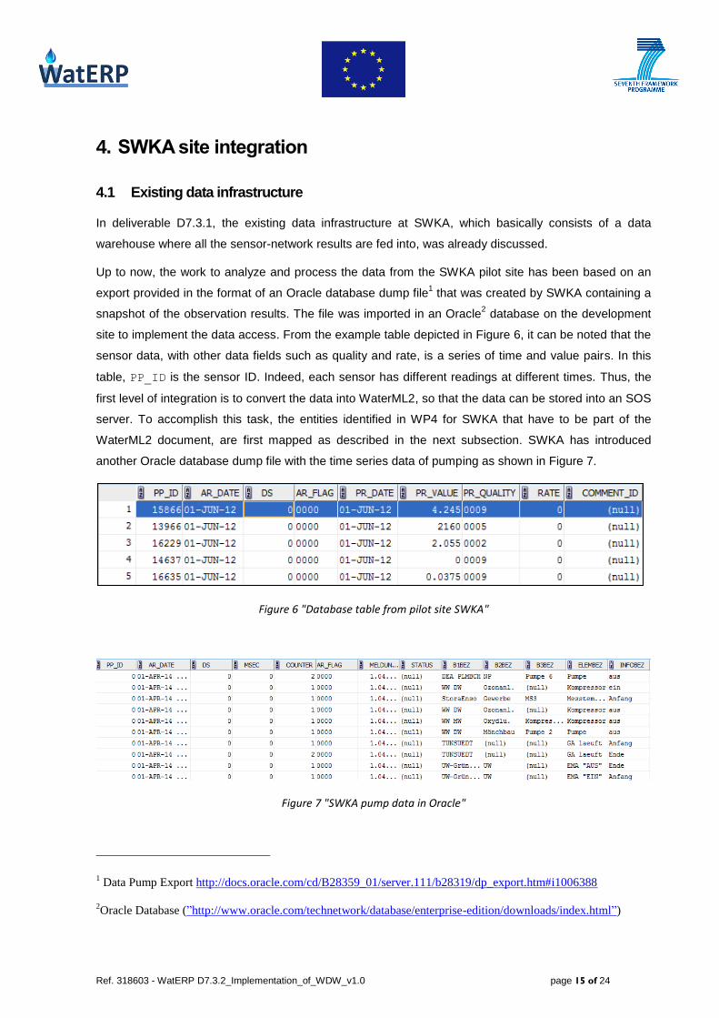
Up to now, the work to analyze and process the data from the SWKA pilot site has been based on an
export provided in the format of an Oracle database dump file1 that was created by SWKA containing a
snapshot of the observation results. The file was imported in an Oracle2 database on the development
site to implement the data access. From the example table depicted in Figure 6, it can be noted that the
sensor data, with other data fields such as quality and rate, is a series of time and value pairs. In this
table, PP_ID is the sensor ID. Indeed, each sensor has different readings at different times. Thus, the
first level of integration is to convert the data into WaterML2, so that the data can be stored into an SOS
server. To accomplish this task, the entities identified in WP4 for SWKA that have to be part of the
WaterML2 document, are first mapped as described in the next subsection. SWKA has introduced
another Oracle database dump file with the time series data of pumping as shown in Figure 7.
Figure 6 "Database table from pilot site SWKA"
Figure 7 "SWKA pump data in Oracle"
1 Data Pump Export http://docs.oracle.com/cd/B28359_01/server.111/b28319/dp_export.htm#i1006388
2Oracle Database (”http://www.oracle.com/technetwork/database/enterprise-edition/downloads/index.html”)
Ref. 318603 - WatERP D7.3.2_Implementation_of_WDW_v1.0 page 16 of 24
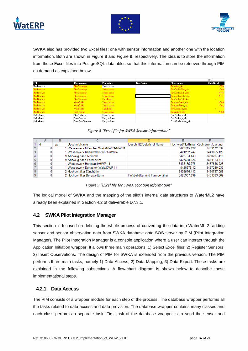
SWKA also has provided two Excel files: one with sensor information and another one with the location
information. Both are shown in Figure 8 and Figure 9, respectively. The idea is to store the information
from these Excel files into PostgreSQL datatables so that this information can be retrieved through PIM
on demand as explained below.
Figure 8 “Excel file for SWKA Sensor Information”
Figure 9 “Excel file for SWKA Location Information”
The logical model of SWKA and the mapping of the pilot’s internal data structures to WaterML2 have
already been explained in Section 4.2 of deliverable D7.3.1.
4.2 SWKA Pilot Integration Manager
This section is focused on defining the whole process of converting the data into WaterML 2, adding
sensor and sensor observation data from SWKA database onto SOS server by PIM (Pilot Integration
Manager). The Pilot Integration Manager is a console application where a user can interact through the
Application Initiation wrapper. It allows three main operations: 1) Select Excel files; 2) Register Sensors;
3) Insert Observations. The design of PIM for SWKA is extended from the previous version. The PIM
performs three main tasks, namely 1) Data Access; 2) Data Mapping; 3) Data Export. These tasks are
explained in the following subsections. A flow-chart diagram is shown below to describe these
implementational steps.
4.2.1 Data Access
The PIM consists of a wrapper module for each step of the process. The database wrapper performs all
the tasks related to data access and data provision. The database wrapper contains many classes and
each class performs a separate task. First task of the database wrapper is to send the sensor and

Ref. 318603 - WatERP D7.3.2_Implementation_of_WDW_v1.0 page 17 of 24
location information from Excel files to the PostgreSQL database tables. For this purpose, PIM allows
the user to select the Excel files for both informations from the system. When the data is inserted into
the system it asks the user to enter the datatable names from the Oracle database if the user wants to
insert observations. On receiving this information from the user, the database wrapper takes the
sensorID from the PostgreSQL table along with other sensor information such as FOI, Procedure,
Phenomenon, B1BEZ, B2BEZ, B3BEZ, ELEMBEZ and location. With this information it checks if
sensorID corresponds to a pump. If it is for a pump, it goes to the pump table in Oracle and checks if
the pump is on or off. If it is on it goes to the sensor Oracle table and gets the time series for the
sensorID for that time when the pump was on. If the pump is off it records the time. All these
timeseries data is brought back and provisioned to the Data Mapping modules that are explained in
next subsection.
4.2.2 Data Mapping
There are three wrappers to perform Data Mapping in SWKA PIM, namely; 1) XML schema wrapper; 2)
XSLT wrapper; and 3) Transformer wrapper. Each wrapper contains many classes with separate
functionality. The XML schema wrapper provides XML schemas files for WaterML 2.0 documents and
registerSensor document on demand when it is required by the Transformer wrapper. The XSLT
wrapper provides stylesheets for InsertObservation, RegisterSensor, and WaterML 2.0
documents when these are required by Transformer Wrapper to replace the values of objects defined in
it. These operations are defined in Document 3.3 “WDW 2nd
prototype” in more detail. The Transformer
wrapper takes the objects from XML Schema files and fills them in by replacing values in XSLT files.
This way it is the Transformers wrapper’s job to generate XML files for WaterML 2.0,
RegisterSensor and InsertObservation documents. But these files are not exported yet. This
task is defined in the next subsection.
Ref. 318603 - WatERP D7.3.2_Implementation_of_WDW_v1.0 page 18 of 24
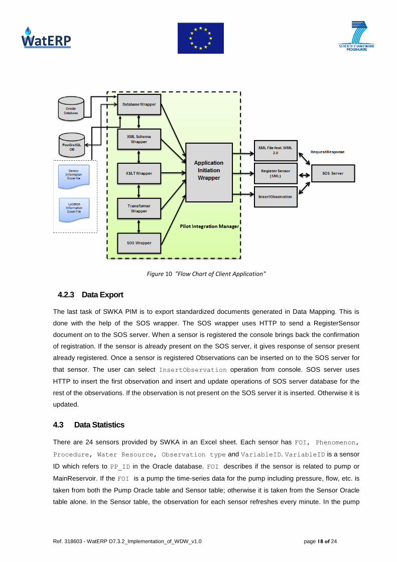
Figure 10 "Flow Chart of Client Application"
4.2.3 Data Export
The last task of SWKA PIM is to export standardized documents generated in Data Mapping. This is
done with the help of the SOS wrapper. The SOS wrapper uses HTTP to send a RegisterSensor
document on to the SOS server. When a sensor is registered the console brings back the confirmation
of registration. If the sensor is already present on the SOS server, it gives response of sensor present
already registered. Once a sensor is registered Observations can be inserted on to the SOS server for
that sensor. The user can select InsertObservation operation from console. SOS server uses
HTTP to insert the first observation and insert and update operations of SOS server database for the
rest of the observations. If the observation is not present on the SOS server it is inserted. Otherwise it is
updated.
4.3 Data Statistics
There are 24 sensors provided by SWKA in an Excel sheet. Each sensor has FOI, Phenomenon,
Procedure, Water Resource, Observation type and VariableID. VariableID is a sensor
ID which refers to PP_ID in the Oracle database. FOI describes if the sensor is related to pump or
MainReservoir. If the FOI is a pump the time-series data for the pump including pressure, flow, etc. is
taken from both the Pump Oracle table and Sensor table; otherwise it is taken from the Sensor Oracle
table alone. In the Sensor table, the observation for each sensor refreshes every minute. In the pump

Ref. 318603 - WatERP D7.3.2_Implementation_of_WDW_v1.0 page 19 of 24
table the sensor is turned to on and off at irregular times. The observations are required to download
only when the pump is on. The data for SWKA for all sensors in a month are approximately 18,000
rows.
4.4 Next Steps
Next steps for SWKA include adding all the sensors from pilot SOS to WDW SOS. To perform this step
for the moment, a script is being used to send data through the REST client. This script sends one
sensor at a time. This procedure will be replaced by a more efficient one to send all sensors at once.
The strategy adopted for the SWKA PIM is very different to the one applied at ACA where it is
reasonable to set up a poller that periodically queries the WaterOneFlow server. In SWKA the situation
is different as new data will only be available once a new export has been triggered in the data
warehouse. Therefore, an application which can be explicitly started after the export has been finished
successfully which is preferable to a system which polls in fixed time periods.
Figure 11 shows the current installation scenario according to the architecture described. The pilot SOS
server is installed inside the “Demilitarized Zone” (DMZ) of the SWKA network whereas the WDW runs
on BDIGITAL’s preproduction server.
Figure 11 "Current Installation Scenario for SWKA"
Ref. 318603 - WatERP D7.3.2_Implementation_of_WDW_v1.0 page 20 of 24
5. Performance
The PIMs have to perform three main tasks as described in chapter 2 which are relevant for the
performance:
1. Accessing the data from the site infrastructure
2. Mapping the data to OGC SOS WaterML2 format
3. Storing the mapped data in the PIM SOS server
The execution of these tasks has to be done without jeopardizing the stability, security and effiency of
the PIMs and the data sources. The performance of each of these steps can vary greatly for different
PIM site integrations.
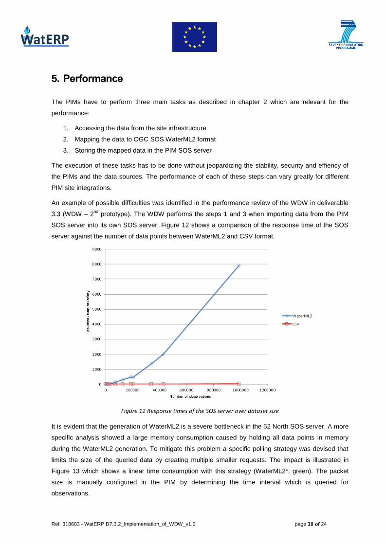
An example of possible difficulties was identified in the performance review of the WDW in deliverable
3.3 (WDW – 2nd
prototype). The WDW performs the steps 1 and 3 when importing data from the PIM
SOS server into its own SOS server. Figure 12 shows a comparison of the response time of the SOS
server against the number of data points between WaterML2 and CSV format.
Figure 12 Response times of the SOS server over dataset size
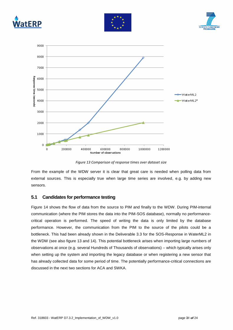
It is evident that the generation of WaterML2 is a severe bottleneck in the 52 North SOS server. A more
specific analysis showed a large memory consumption caused by holding all data points in memory
during the WaterML2 generation. To mitigate this problem a specific polling strategy was devised that
limits the size of the queried data by creating multiple smaller requests. The impact is illustrated in
Figure 13 which shows a linear time consumption with this strategy (WaterML2*, green). The packet
size is manually configured in the PIM by determining the time interval which is queried for
observations.
Ref. 318603 - WatERP D7.3.2_Implementation_of_WDW_v1.0 page 21 of 24
Figure 13 Comparison of response times over dataset size
From the example of the WDW server it is clear that great care is needed when polling data from
external sources. This is especially true when large time series are involved, e.g. by adding new
sensors.
5.1 Candidates for performance testing
Figure 14 shows the flow of data from the source to PIM and finally to the WDW. During PIM-internal
communication (where the PIM stores the data into the PIM-SOS database), normally no performance-
critical operation is performed. The speed of writing the data is only limited by the database
performance. However, the communication from the PIM to the source of the pilots could be a
bottleneck. This had been already shown in the Deliverable 3.3 for the SOS-Response in WaterML2 in
the WDW (see also figure 13 and 14). This potential bottleneck arises when importing large numbers of
observations at once (e.g. several Hundreds of Thousands of observations) – which typically arises only
when setting up the system and importing the legacy database or when registering a new sensor that
has already collected data for some period of time. The potentially performance-critical connections are
discussed in the next two sections for ACA and SWKA.

Ref. 318603 - WatERP D7.3.2_Implementation_of_WDW_v1.0 page 22 of 24
Figure 14 Flow chart of the PIM and WDW components working together. The candidates for performance
testing are marked as dashed and dotted arrows.
5.2 Performance ACA
For the ACA PIM all time-series data is downloaded from a web service delivering WaterOneFlow data
(communication path (1) in Figure 14). From the WatERP project point-of-view this WS is considered an
operational ACA software used as a black-box and out-of-reach for manipulation by the WatERP team.
So, one can speculate about its internal implementation, strengths and weaknesses, but definitely, any
polling behaviour that might destabilise this server should be avoided. Further, it should not be
expected that the server connection is always completely reliable. Consequently, for data polling from
the WaterOneFlow server, the same packeting mechanism as in the WDW service is employed. This
realizes a conservative communication strategy that does not overstrain the web server at ACA side.
For the following lines one should bear in mind that the WaterOneFlow is an external web service. The
testing of PIM should be run without overloading the service. Therefore currently five concurrent threads
are concerned with polling data, each of them processing a single sensor at a time. Only after retrieving
all available data for that sensor, the thread will advance to the next sensor. For large time series
(which normally only occur when a new sensor is registered and legacy data is imported) this may take
a significant amount of time. If more than five of these time-consuming jobs (i.e. more than five new
sensors with more than several tens of thousands observations) occur, retrieval of data from other

Ref. 318603 - WatERP D7.3.2_Implementation_of_WDW_v1.0 page 23 of 24
sensors would be blocked by these operations for some time. This may become a problem especially
when a running WatERP system with important real-time analyses is on-the-fly extended by new
sensors with large datasets such that the import of the legacy data block the polling of an already-
registered operational sensor such that the real-time usage of this sensor’s data is delayed for some
time. It is possible to increase manually the thread count of the poller in the configuration of the PIM .
Further, one may increase the size of the data blocks to be retrieved (which leads to less
communication and administration overhead, but may lead to the above-explained problems with the
memory management of the SOS server). Such actions need careful adjustment so that the web
service is not overstrained. But all such fine tuning is dependent on the concrete hardware and software
situation in the actual running environment and has been chosen cautiously for the prototypes in the
pilot environments. For an operational solution, this has to be adjusted to the conditions of that
environment. .
During the first test runs with a fully operational PIM-WDW set-up and real-life data of ACA, one sensor
was registered in the PIM. In one hour, about 50,000 observations could be transferred. Hence, there is
no problem to import all existing ACA legacy data in a reasonable amount of time (for the ACA data
volume, refer to Subsection 3.1).
5.3 Performance SWKA
For the SWKA PIM all time-series data resides in a local database. Therefore no performance issue is
expected when retrieving the data. Here the main issue lies in mapping the data and storing it into the
SOS server. Again this import is a database operation which does not have the limitations of a web
service.
During the first test runs with a fully operational PIM-WDW set-up and artificial test data for SWKA
simulating 50 observations for each of the 24 sensors, the import took about 2 seconds in total. Hence,
integration of the full SWKA legacy database (see Subsection 4.3) will be no problem.
Ref. 318603 - WatERP D7.3.2_Implementation_of_WDW_v1.0 page 24 of 24
6. Conclusions and future work
This section summarizes the activities performed so far and describes the next steps.
In the first version of the WDW piloting, the existing data infrastructure were analysed and the sources
for observation result data were identified for both clients, ACA and SWKA. In this second piloting
phase, for both pilots the access to the pilot data has been implemented. The implementation of the
data access layer has been fully completed for both pilots and small adaptations have been realized
compared to the first version of WDW piloting.
Regarding the mapping of the pilots’ data to the ontology, an additional mapping of the WaterML1 data
to WaterML2 has been realized for ACA. Here, especially observed property and offering had to
be adjusted. Afterwards the list of required sensors has been defined and added to the sensor list that
controls the polling. For SWKA, the missing information for mapping has been acquired in the reporting
period and was used to finalize the mapping work, in particular the mapping of the sensor PP_IDs to
WaterML2.
The generation of the WaterML2 documents has been implemented for both pilots and constitutes the
basis for generating the ontology within the WDW. SOS clients for registering new sensors and
inserting observations have been completed for both pilots and have been integrated into the overall
architecture of the pilot hardware and software environments.
After all, the technical infrastructure for WDW filling from pilots’ real-world data has been fully
completed, installed in the pilot sites and exemplarily tested with pilot data. In the last phase of the
project, a regular data flow between pilots and WDW will be established and tested for stability and
performance. To find possible performance problems on the PIM there should be some performance
testing on retrieving the data from the pilots and store it in the SOS Server database. Therefore some
performance measurements for the SWKA PIM are planed. The data from SWKA should be read from a
database on the local machine. Then the PIM should be monitored while writing the data in the
PostgreSQL database of the SOS server. Regarding the WDW piloting, the last project phase will not
only be focussed on storing data from the pilot sites, but also accessing them for analysis purposes and
serving as a data layer for other WatERP tools developed in WP4 and WP5.