waters micromass lct premier mass · pdf filesafety information general the waters micromass...
TRANSCRIPT

Waters MicromassLCT Premier
Mass SpectrometerOperator’s Guide
34 Maple Street Milford, MA 01757
71500067902, Revision B

NOTICE
The information in this document is subject to change without notice and should not be construed as a commitment by Waters Corporation. Waters Corporation assumes no responsibility for any errors that may appear in this document. This document is believed to be complete and accurate at the time of publication. In no event shall Waters Corporation be liable for incidental or consequential damages in connection with, or arising from, the use of this document.
© 2004 WATERS CORPORATION. PRINTED IN THE UNITED STATES OF AMERICA AND IRELAND. ALL RIGHTS RESERVED. THIS DOCUMENT OR PARTS THEREOF MAY NOT BE REPRODUCED IN ANY FORM WITHOUT THE WRITTEN PERMISSION OF THE PUBLISHER.
Micromass and Waters are registered trademarks, and ESCi, LCT Premier, LockSpray, MassLynx, MUX-Technology, NanoLockSpray, and ZSpray are trademarks of Waters Corporation.
PEEK is a trademark of Victrex Corporation.
Rheodyne is a registered trademark of Rheodyne, L.P.
Upchurch is a registered trademark of Scivex, Inc.
Windows is a registered trademark of Microsoft Corporation.
All other trademarks or registered trademarks are the sole property of their respective owners.

Safety Information
GeneralThe Waters Micromass LCT Premier is designed solely for use as a mass spectrometer; any attempt to use it for any other purpose is liable to damage the instrument and will invalidate its warranty.
The mass spectrometer conforms to European standard EN61010-1:2001, Safety Requirements for electrical equipment for measurement, control, and laboratory use - Part 1: General requirements.
The instrument has been designed and tested in accordance with recognized safety standards. If the instrument is used in a manner not specified by the manufacturer, the protection provided by the instrument may be impaired.
Whenever the safety protection of the instrument has been compromised, disconnect the instrument from all power sources and secure the instrument against unintended operation.
The instrument must be installed in such a manner that the user can easily access and isolate the power source.
Safety SymbolsWarnings in this guide, or on the instrument, must be observed during all phases of service, repair, installation, and operation of the instrument. Failure to comply with these precautions violates the safety standards of the design and intended use of the instrument.
Waters Corporation assumes no liability for failure to comply with these requirements.
The following safety symbols may be used in this guide or on the instrument. A Warning is an instruction that draws attention to the risk of injury or death. A Caution is an instruction that draws attention to the risk of damage to the instrument

Consignes de sécurité
GénéralitésLe LCT Premier de Waters Micromass est destiné exclusivement à être utilisé comme spectromètre de masse. Tout usage détourné du LCT Premier risquerait d’endommager l’instrument et invaliderait sa garantie.
Le spectromètre de masse LCT Premier de Waters Micromass est conforme à la norme européenne EN61010-1 (2001) : Règles de sécurité pour appareils électriques de mesurage, de régulation et de laboratoire. - Partie 1 : prescriptions générales.
Cet instrument a été conçu et testé dans le respect de normes de sécurité approuvées. Toute utilisation de l’instrument non conforme aux instructions du fabricant risque de remettre en cause la protection assurée par l’instrument.
Dans le cas où la sécurité de l’utilisateur se trouverait compromise, débranchez le cordon d’alimentation de l’instrument et assurez-vous qu’il ne pourra être mis en marche par mégarde.
L’instrument doit être installé de façon à faciliter l’accès de l’utilisateur au bloc d’alimentation électrique.
Pictogrammes de sécuritéLes avertissements présents dans le manuel de l’utilisateur ou sur l’instrument-même doivent être scrupuleusement pris en considération, et ce à tout moment, que ce soit pendant l’entretien, la réparation, l’installation ou le fonctionnement de l’instrument. Tout défaut d’application de ces règles de sécurité serait considéré comme une violation des normes de sécurité relatives à la conception et à l’usage prévu de l’instrument.
Waters ne saurait voir sa responsabilité engagée en cas de manquement de l’utilisateur à respecter les consignes de sécurité.
Vous pourrez rencontrer les pictogrammes qui suivent dans le manuel de l’utilisateur ou sur l’instrument. Est appelée Avertissement toute instruction destinée à attirer l’attention de l’utilisateur sur l’existence d’un risque de blessure ou de mort. Est appelée Attention toute instruction destinée à informer l’utilisateur de la présence d’un risque d’endommagement de l’instrument.

Warning: This is a general warning symbol, indicating that there is a potential health or safety hazard; the user should refer to this operators guide for instructions.
Avertissement: Risque de blessure de l’utilisateur ou risque d’endommagement de l’instrument. Consultez le manuel de l’utilisateur pour instructions.
Warning: This symbol indicates that hazardous voltages may be present.
Avertissement: Présence de lignes haute tension.
Warning: This symbol indicates that hot surfaces may be present.
Avertissement: Ce pictogramme indique la presence de surfaces chaudes.
Warning: This symbol indicates that there is danger from corrosive substances.
Avertissement: Substances corrosives.
Warning: This symbol indicates that there is danger from toxic substances.
Avertissement: Substances toxiques.
Warning: This symbol indicates that there is danger from flammable substances.
Avertissement: Substances inflammables.

Warning: This symbol indicates that there is danger from laser radiation.
Avertissement: Risque de radiations laser.
Warning: This symbol indicates that there is a danger from UV radiation.
Avertissement: Risque de radiations UV.
Warning: This symbol indicates danger of contamination by a biological agent that constitutes a threat to humans.
Avertissement: Ce pictogramme indique la présence d’un risque de contamination par un agent biologique constituant un danger potentiel pour l’utlisateur.
Caution: This is a general caution symbol, indicating that care must be taken to avoid the possibility of damaging the instrument, or affecting its operation.
Attention: Il convient de prendre les précautions nécessaires afin de ne pas risquer d’endommager l’instrument ou de nuire à son fonctionnement.

LCT Premier Mass Spectrometer Information
Intended UseThe Micromass LCT Premier Mass Spectrometer can be used as a research tool to deliver authenticated exact mass. It is not for use in diagnostic procedures.
Biological HazardWhen you analyze physiological fluids, take all necessary precautions and treat all specimens as potentially infectious. Precautions are outlined in “CDC Guidelines on Specimen Handling,” CDC – NIH Manual, 1984.
Chemical HazardGood Laboratory Practice should be followed when using potentially toxic, biohazardous, caustic, or flammable solvents and analytes.
Flammable Solvents Operation Hazard
If flammable solvents are used, you should ensure that the nitrogen supply pressure will not fall below 4 bar during the analysis.
CalibrationFollow acceptable methods of calibration with pure standards to calibrate methods. Use a minimum of five standards to generate a standard curve. The concentration range should cover the entire range of quality-control samples, typical specimens, and atypical specimens.
Quality ControlRoutinely run three quality-control samples. Quality-control samples should represent subnormal, normal, and above-normal levels of a compound. Ensure that quality-control sample results are within an acceptable range, and evaluate precision from day to day and run to run. Data collected when quality-control samples are out of range may not be valid. Do not report this data until you ensure that system performance is acceptable.
Caution: If the nitrogen supply pressure falls below 4 bar, the instrument will switch off the nitrogen supply and admit air into the source. If flammable solvents are used, there is a potential ignition hazard.

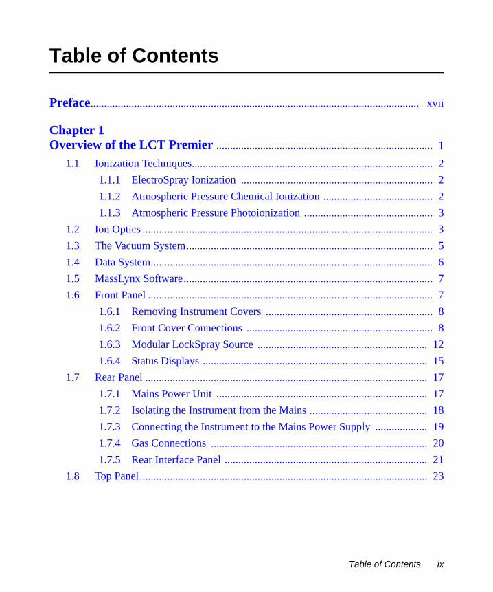
Table of Contents
Preface........................................................................................................................ xvii
Chapter 1 Overview of the LCT Premier ............................................................................... 1
1.1 Ionization Techniques........................................................................................ 21.1.1 ElectroSpray Ionization ...................................................................... 21.1.2 Atmospheric Pressure Chemical Ionization ........................................ 21.1.3 Atmospheric Pressure Photoionization ............................................... 3
1.2 Ion Optics .......................................................................................................... 31.3 The Vacuum System.......................................................................................... 51.4 Data System....................................................................................................... 61.5 MassLynx Software........................................................................................... 71.6 Front Panel ........................................................................................................ 7
1.6.1 Removing Instrument Covers ............................................................. 81.6.2 Front Cover Connections .................................................................... 81.6.3 Modular LockSpray Source .............................................................. 121.6.4 Status Displays .................................................................................. 15
1.7 Rear Panel ....................................................................................................... 171.7.1 Mains Power Unit ............................................................................. 171.7.2 Isolating the Instrument from the Mains ........................................... 181.7.3 Connecting the Instrument to the Mains Power Supply ................... 191.7.4 Gas Connections ............................................................................... 201.7.5 Rear Interface Panel .......................................................................... 21
1.8 Top Panel......................................................................................................... 23
Table of Contents ix

Chapter 2 Basic Introduction to Instrument Operation ................................................. 25
2.1 Installing the Electrospray Probe .................................................................... 252.2 Opening MassLynx ......................................................................................... 262.3 Using the Tune Window.................................................................................. 28
2.3.1 Obtaining a Mass Spectrum .............................................................. 292.3.2 Setting the Correct Mass Range ........................................................ 352.3.3 Acquiring Data from the Tune Window ........................................... 362.3.4 Checking the Resolution ................................................................... 39
Chapter 3 Calibration ................................................................................................................. 41
3.1 Nominal Mass Measurement .......................................................................... 413.2 TDC Settings ................................................................................................... 453.3 MCP Setup Wizard.......................................................................................... 473.4 Calibrating for Accurate Mass ........................................................................ 51
3.4.1 Calibration Solution .......................................................................... 563.5 Deadtime Correction ....................................................................................... 57
3.5.1 Digital Deadtime Correction Wizard ................................................ 57
Chapter 4 Advanced Operation ............................................................................................... 61
4.1 Applying a Single-Point Lock Mass Correction ............................................. 614.1.1 Using LockSpray with a Sample List Acquisition ............................ 61
4.2 Dynamic Range Enhancement ........................................................................ 674.2.1 Dynamic Range Enhancement Settings ............................................ 694.2.2 Using DRE ........................................................................................ 74
4.3 Setting Up an LC Inlet .................................................................................... 784.4 Shutting Down for the Day ............................................................................. 83
4.4.1 Automatically Shutting Down for the Day ....................................... 83
x Table of Contents

4.4.2 Starting Up ........................................................................................ 864.5 The MS Method Editor ................................................................................... 87
4.5.1 Setting Up a MS Scan Function ........................................................ 87
Chapter 5 APCI, APPI and ESCi ........................................................................................... 95
5.1 APCI Operation............................................................................................... 955.1.1 Installing the APCI probe ................................................................. 955.1.2 Tuning for APCI Operation .............................................................. 97
5.2 The Combined APPI/APCI Source ............................................................... 1025.2.1 APCI Probe ..................................................................................... 1025.2.2 APPI Lamp Drive Assembly .......................................................... 102
5.3 Installing the Combined APPI/APCI Source ................................................ 1055.4 Operating in APPI and Dual APPI/APCI Modes.......................................... 106
5.4.1 APPI Mode ..................................................................................... 1065.4.2 Dual APPI/APCI Mode .................................................................. 111
5.5 ESCi Multi-Mode Ionization......................................................................... 1165.5.1 Preparing for ESCi Operation ......................................................... 116
5.6 Creating an MS Method Files for Dual Mode Ionization ............................. 119
Chapter 6 NanoLockSpray Interface .................................................................................. 123
6.1 Overview of NanoLockSpray........................................................................ 1236.1.1 NanoLockSpray Installation ........................................................... 1246.1.2 Nano Reference Probe Assembly Instructions ............................... 126
6.2 Operation and Tuning.................................................................................... 1366.3 Data Processing ............................................................................................. 1376.4 Adding NanoFlow Options ........................................................................... 138
6.4.1 Glass Capillary Option .................................................................... 1396.5 Nano-LC Option............................................................................................ 141
6.5.1 Operating the Nano-LC Option ...................................................... 143
Table of Contents xi

6.6 Changing Options.......................................................................................... 144
Chapter 7 MUX-technology .................................................................................................... 145
7.1 The MUX-technology Interface .................................................................... 1457.2 Installing the MUX-technology Interface ..................................................... 1487.3 Operation and Tuning.................................................................................... 152
Chapter 8 Preventative Maintenance .................................................................................. 157
8.1 Maintenance Schedule................................................................................... 1578.2 Safety and Handling ...................................................................................... 1588.3 Cooling Fans and Air Filters ......................................................................... 159
8.3.1 Changing the Air Filter ................................................................... 1598.4 The Vacuum System...................................................................................... 161
8.4.1 Gas-Ballasting and Rotary Pump Oil Recirculation ....................... 1618.4.2 Replacing the Activated Alumina in the Foreline Trap ................. 1648.4.3 Checking the Rotary Pump Oil ....................................................... 1648.4.4 Changing the Rotary Pump Oil ....................................................... 1648.4.5 Changing the Oil Mist and Odor Filter Elements ........................... 166
8.5 Cleaning the Source Components ................................................................. 1698.5.1 Overview ......................................................................................... 1698.5.2 Removing the Probe from the Source ............................................. 1708.5.3 Removing the Sample Cone ........................................................... 1708.5.4 Removing the Ion Source Enclosure and Ion Block ....................... 1738.5.5 Removing the Source Assembly from the Instrument .................... 1748.5.6 Disassembling the Source Ion Block .............................................. 1778.5.7 Cleaning the Sample Cone and Cone Gas Cone ............................. 1828.5.8 Cleaning the Source Components ................................................... 1848.5.9 Cleaning the Ion Block ................................................................... 1858.5.10 Cleaning the Isolation Valve Stem .................................................. 185
xii Table of Contents

8.5.11 Reassembling the Source Ion Block ............................................... 1868.5.12 Reassembling and Fitting the Source Ion Guide Assembly to the
Instrument 1868.5.13 Fitting the Ion Block and Ion Source Enclosure ............................. 1868.5.14 Fitting the Sample Cone ................................................................. 1878.5.15 MCP Conditioning .......................................................................... 187
8.6 Cleaning or Replacing the ESI Probe Tip ..................................................... 1888.7 Cleaning or Replacing the Corona Discharge Pin......................................... 1898.8 Cleaning the APCI Probe Tip........................................................................ 1908.9 Replacing the Ion Block Cartridge Heater .................................................... 1918.10 Replacing the ESI Probe Capillary................................................................ 195
8.10.1 Installing the New Capillary ........................................................... 2008.11 Replacing the APCI Probe Capillary ............................................................ 205
8.11.1 Installing the New Capillary ........................................................... 2108.12 Replacing the APCI Probe Heater................................................................. 2168.13 Maintaining the APPI Lamp ......................................................................... 219
8.13.1 Changing the Lamp Bulb ................................................................ 2198.13.2 Cleaning the Lamp Window ........................................................... 220
8.14 Performing LockSpray Maintenance ............................................................ 2218.14.1 LockSpray ....................................................................................... 2218.14.2 Performing NanoLockSpray Maintenance ..................................... 226
8.15 Performing MUX-technology Maintenance.................................................. 2318.15.1 Cleaning the Sampling Rotor Assembly ......................................... 2318.15.2 Reassembling the Sampling Rotor Assembly ................................. 2358.15.3 Replacing the ElectroSpray Probe Tip ............................................ 2358.15.4 Replacing a Sample Capillary ......................................................... 237
Chapter 9 Fault Finding ........................................................................................................... 243
9.1 Fault Finding ................................................................................................. 243
Table of Contents xiii

9.1.1 Instrument Stops Responding to Commands from MassLynx. ...... 2439.1.2 No Beam ......................................................................................... 2459.1.3 Unsteady Beam ............................................................................... 2459.1.4 High Backpressure .......................................................................... 2469.1.5 Loss of Sensitivity .......................................................................... 2479.1.6 Incorrect Isotope Distributions ....................................................... 2479.1.7 High Noise Levels .......................................................................... 247
9.2 LockSpray Fault Finding............................................................................... 2489.3 MUX Fault Finding....................................................................................... 248
9.3.1 Checking the Relative Sensitivity of Each Spray ........................... 2489.3.2 Sampling Rotor does not Rotate ..................................................... 2499.3.3 Tune Window Readbacks Indicate no Voltages Present ................. 249
9.4 Contacting Waters ......................................................................................... 249
Appendix A Starting Up and Shutting Down the Instrument ........................................ 251
A.1 Starting the LCT Premier .............................................................................. 251A.2 Shutting Down the LCT Premier .................................................................. 252
A.2.1 Emergency Instrument Shutdown ................................................... 252A.2.2 Overnight Instrument Shutdown ..................................................... 252A.2.3 Complete Instrument Shutdown ..................................................... 252
A.3 Automatic Startup and Shutdown.................................................................. 253A.3.1 The Shutdown Editor ...................................................................... 253A.3.2 The Shutdown Editor Toolbar ........................................................ 254A.3.3 Shutdown Page ............................................................................... 254A.3.4 Auto Control Tasks Page ................................................................ 258A.3.5 Shutdown / Startup Log .................................................................. 261
xiv Table of Contents

Appendix B Configuring the Rotary Pumps for the Local Voltage Supply .............. 265
Appendix C Setting Up the Syringe Pump ............................................................................ 267
Appendix D Tune Window .......................................................................................................... 269
D.1 Tune Window Basics..................................................................................... 269D.1.1 Opening the Tune Window ............................................................. 269D.1.2 Selecting the Ionization Mode ........................................................ 270D.1.3 Controlling Gas Flows .................................................................... 270D.1.4 Controlling the Syringe Pump ........................................................ 270D.1.5 Tuning Setup ................................................................................... 271D.1.6 RF Ramping Setup .......................................................................... 271D.1.7 Controlling the Display of Readback Windows ............................. 272D.1.8 Changing Tune Parameter Settings ................................................. 273D.1.9 Instrument Parameter Files ............................................................. 273D.1.10 Printing Tune Information .............................................................. 274D.1.11 Selecting the Span of a Displayed Peak .......................................... 274D.1.12 Changing the Gain of a Displayed Peak ......................................... 275
D.2 Customizing the Peak Display ...................................................................... 275D.2.1 Opening the Peak Display Menu .................................................... 275D.2.2 Customizing the Colors and Numbers of Displayed Traces ........... 276D.2.3 Customizing the Peak Trace Line Appearance ............................... 276D.2.4 Customizing the Peak Intensity Display ......................................... 277D.2.5 Customizing the Peak Display Grid ................................................ 277D.2.6 Selecting the Instrument Name ....................................................... 277
D.3 Tune Window Parameters ............................................................................. 278D.3.1 Transfer Page .................................................................................. 278D.3.2 Analyser Page ................................................................................. 280
Table of Contents xv

D.3.3 Diagnostics Page ............................................................................. 282
Appendix E Performance Specifications ................................................................................ 283
E.1 Resolution in Positive Ion (V Mode) ............................................................ 283E.2 Resolution in Positive Ion (W Mode) ........................................................... 283E.3 Resolution in Negative Ion (V Mode)........................................................... 283E.4 Resolution in Negative Ion (W Mode).......................................................... 284E.5 Sensitivity in Positive Ion ............................................................................. 284E.6 Sensitivity in Negative Ion............................................................................ 284E.7 Mass Calibration Accuracy ........................................................................... 284E.8 Mass Measurement Accuracy ....................................................................... 286E.9 Chromatographic Signal to Noise ................................................................. 287
Appendix F APPI, APCI, and Dual APPI/APCI Modes .................................................. 289
F.1 About APPI Mode......................................................................................... 289F.2 About APCI Mode ........................................................................................ 290F.3 About Dual APPI/APCI Mode...................................................................... 290
Appendix G MUX Plumbing ....................................................................................................... 293
G.1 Using Waters 1525 Pumps with a Waters 2777 Autosampler....................... 293G.1.1 MassLynx Control ........................................................................... 294
G.2 Using a Gilson 215/889 Autosampler ........................................................... 296G.2.1 Plumbing a 4 or 8 -Probe Gilson 215/889 ...................................... 297G.2.2 MassLynx Control ........................................................................... 299
Index ........................................................................................................................... 305
xvi Table of Contents

PrefaceThe Waters® Micromass® LCT Premier™ Mass Spectrometer is intended for a wide variety of users whose familiarity with Mass Spectrometers, computers and software ranges from novice to expert. This guide describes an introduction to the running and maintenance of the instrument. It also provides basic instructions on how to tune and calibrate the instrument and acquire data
Related DocumentationWaters Licenses, Warranties, and Support: Provides software license and warranty information, describes training and extended support, and tells how Waters handles shipments, damages, claims, and returns.
Online Documentation
MassLynx Help: Describes all MassLynx™ windows, menus, menu selections, and dialog boxes for the base software and software options. Also included are help Files on Inlet Control, Interfacing, Security and any application software that may have been purchased.
MassLynx ReadMe File: Describes product features and enhancements, helpful tips, installation and/or configuration considerations, and changes since the previous version.
Printed Documentation for Base Product
Waters Micromass LCT Premier Operator’s Guide: Provides an introduction to the running and maintenance of the Instrument and also basic instructions on how to acquire data and calibrate the instrument.
Waters Micromass LCT Premier Site Preparation Guide: Describes the recommended environmental conditions and power supplies that are required for operation of the instrument.
MassLynx User’s Guide: Provides a comprehensive introduction to the MassLynx software. Describes the basics of how to use MassLynx software to acquire data develop an acquisition method, review and process results, and print a report.
MassLynx Interfacing Guide: Provides information on how to interface MassLynx with other Software applications.
xvii

MassLynx Inlet Control Guide: Provides information on how to install and run Autosamplers, LC and GC systems, UV detectors using MassLynx.
MassLynx Security User’s Guide: Describes how to add security to your MassLynx system.
Printed Documentation for Software Options
QuanLynx User’s Guide: Describes the procedures for installing, configuring and using QuanLynx Software.
OpenLynx User’s Guide: Describes the procedures for installing, configuring and using OpenLynx Software.
FractionLynx User’s Guide: Describes the procedures for installing, configuring and using FractionLynx Software.
MetaboLynx User’s Guide: Describes the procedures for installing, configuring and using MetaboLynx Software.
BioLynx and ProteinLynx User’s Guide: Describes the procedures for installing, configuring and using BioLynx and ProteinLynx Software.
MicrobeLynx User’s Guide: Describes the procedures for installing, configuring and using MicrobeLynx Software.
NeoLynx User’s Guide: Describes the procedures for installing, configuring and using NeoLynx Software.
TargetLynx User’s Guide: Describes the procedures for installing, configuring and using TargetLynx Software.
ChromaLynx User’s Guide: Describes the procedures for installing, configuring and using ChromaLynx Software.
Documentation on the Web
Related product information and documentation can be found on the World Wide Web. Our address is http://www.waters.com.
xviii

Documentation ConventionsThe following conventions can be used in this guide:
Notes
Notes call out information that is helpful to the operator. For example:
Note: Record your result before you proceed to the next step.
Convention Usage
Italic Italic indicates information that you supply such as variables. It also indicates emphasis and document titles. For example, “Replace file_name with the actual name of your file.”
Courier Courier indicates examples of source code and system output. For example, “The SVRMGR> prompt appears.”
Courier Bold Courier bold indicates characters that you type or keys you press in examples of source code. For example, “At the LSNRCTL> prompt, enter set password oracle to access Oracle.”
Keys The word key refers to a computer key on the keypad or keyboard. Screen keys refer to the keys on the instrument located immediately below the screen. For example, “The A/B screen key on the 2414 Detector displays the selected channel.”
… Three periods indicate that more of the same type of item can optionally follow. For example, “You can store filename1, filename2, … in each folder.”
> A right arrow between menu options indicates you should choose each option in sequence. For example, “Select File > Exit” means you should select File from the menu bar, then select Exit from the File menu.
xix

xx

Chapter 1 Overview of the LCT Premier
The LCT Premier™ time-of-flight (TOF) mass spectrometer (Figure 1-1) features a ZSpray source with electrospray ionization (ESI) and modular LockSpray™ interface. Options include IonSABRE™ atmospheric pressure chemical ionization (APCI), atmospheric pressure photoionization (APPI), electrospray chemical ionization (ESCI), NanoLockSpray™ and MUX-Technology™.
Figure 1-1 The LCT Premier
The LCT Premier uses ion guide technology for optimum transfer of ions from the source to the orthogonal acceleration time of flight (oa-TOF) mass analyzer. Ion detection is by dual microchannel plate detector assembly. Data is acquired by a 4.0 GHz time-to-digital converter (TDC) and histogrammed in an embedded PC. Instrument control and data acquisition is by the MassLynx™ software system.
1

1.1 Ionization Techniques
Using the Zspray atmospheric pressure ionization (API) source, three techniques are available.
1.1.1 ElectroSpray IonizationElectrospray ionization (ESI) takes place as a result of imparting a strong electrical charge to the eluent as it emerges from the nebulizer. An aerosol of charged droplets emerges from the nebulizer. These undergo a reduction in size by solvent evaporation until they have attained a sufficient charge density to allow sample ions to be ejected from the surface of the droplet (ion evaporation).
A characteristic of ESI spectra is that ions may be singly or multiply charged. Since the mass spectrometer separates ions according to their mass-to-charge ratio (m/z), compounds of high molecular weight can be determined if multiply charged ions are formed.
Eluent flows up to 1 mL/min can be accommodated although it is often preferable with electrospray ionization to split the flow such that 5-50 µL/min of eluent enters the mass spectrometer.
The optional NanoLockSpray interface allows electrospray ionization to be performed in the flow rate range 5 to 1000 nL/min.
For a given sample concentration, the ion currents observed in nanoflow are comparable to those seen in normal flow rate electrospray. Great sensitivity gains are therefore observed when similar scan parameters are used, due to the great reductions in sample consumption.
1.1.2 Atmospheric Pressure Chemical IonizationAPCI generally produces protonated or deprotonated molecular ions from the sample via a proton transfer (positive ions) or proton abstraction (negative ions) mechanism. The sample is vaporized in a heated nebulizer before emerging into a plasma consisting of solvent ions formed within the atmospheric source by a corona discharge. Proton transfer or abstraction then occurs between the solvent ions and the sample. Eluent flows up to 2 mL/min can be accommodated without splitting the flow.
2 Overview of the LCT Premier

1.1.3 Atmospheric Pressure PhotoionizationAPPI uses photons generated by a krypton discharge UV lamp (~10.2 eV) to produce sample ions from vaporized LC eluent. Direct photoionization of the sample molecule occurs when the photon energy is greater than the ionization potential of the sample molecule.
The APPI source option incorporates a UV lamp, powered by a separate control unit. The sample is introduced into the source via the APCI IonSABRE probe. This produces a stream of sample and solvent species that undergo photon-induced ion-molecule reactions.
An electrode, known as a repeller, is used to deflect and focus the sample ions produced towards the sample cone for introduction into the mass spectrometry system for analysis.
1.2 Ion Optics
Figure 1-2 shows the principle components of the ion optical system. Ions generated in the ZSpray source are transferred to the TOF analyses via two differentially pumped ion guides and a hexapole. As ions travel from the pusher to the detector they are separated in mass according to their flight times, with ions of the highest mass to charge ratio (m/z) arriving later.
The pusher may be operated at repetition frequencies of up to 30 kHz, resulting in a full spectrum being recorded by the detector every 33 microseconds. Each spectrum is summed in the histogram memory of the time-to-digital converter until the histogrammed spectrum is transferred to the host PC.
Ion Optics 3

Figure 1-2 Ion Optics in V Mode
If you request an acquisition rate of 1 spectrum/second, each spectrum viewed on the host PC will be the result of summing up to 30,000 individual spectra recorded at the detector.
In V mode, the beam takes a V-shaped path to the detector by being directed towards the reflectron and then towards the MCP detector.
In W mode the beam follows a W-shaped path to the detector by being reflected off the W lens and back towards the reflectron before being reflected back towards the MCP detector (Figure 1-3). This unique flight path ensures that the wide mass range the analysis is not compromised.
Reflectron
Pusher Detector
Ion GuideTransferOptics
IsolationValve
Hexapole(Ion Bridge)
LockSprayLockSpray Baffle
Orthogonal Inlet Probe
4 Overview of the LCT Premier

Figure 1-3 Ion Optics in W Mode
Unlike scanning instruments, the TOF mass spectrometer performs parallel detection of all masses within the spectrum at very high sensitivity and acquisition rates. This characteristic is of particular advantage when the instrument is coupled to fast chromatography, since each spectrum is representative of the sample composition at that point in time, irrespective of how rapidly the sample composition is changing.
1.3 The Vacuum System
Figure 1-4 shows the vacuum system which is made up of maintained by three vacuum pumps:
• A three-stage slit-flow turbomolecular pump is used to pump ion guide 2, the hexapole, and the TOF regions. This pump requires no user maintenance.
• An Edwards E2M28 rotary pump provides backing for the turbo pump, and also pumps the source ion guide 1 region.
Pusher Detector
Reflectron
W Lens
The Vacuum System 5

• An Edwards E1M18 rotary pump pumps the source block region.
Figure 1-4 Vacuum System
The source pressure (the pressure in the ion guide 1 region) is monitored by a Pirani gauge. This gauge requires no user maintenance.
The analyzer pressure (the pressure in the TOF region) is monitored by an active inverted magnetron (Penning) gauge.
For details of vacuum system maintenance, see Section 8.4, The Vacuum System.
1.4 Data System
The data system collects information from the mass analyzer. The data system consists of:
• An embedded PC• An external workstation• The MassLynx software
The workstation-based data system, incorporating the MassLynx software, controls the mass spectrometer and, if applicable, the HPLC system, autosampler, divert valve, or
2-stage Source PumpingE1M18 E2M28
3-Stage Air Cooled Turbo Pump
6 Overview of the LCT Premier

injector valve. The workstation uses the Windows® graphical environment and provides full user interaction using either the keyboard or mouse. MassLynx provides full control of the system, including setting up and running selected HPLC systems, tuning the instrument, acquiring data, and data processing. MassLynx instrument control uses an embedded PC to process all data. A network link provides communication between the workstation and the embedded PC.
The data system can sample analog inputs and thus store data from conventional LC detectors, such as an ultraviolet (UV) detector or evaporative light scattering detector (ELSD), simultaneously with acquired mass spectral data. It can also acquire UV photodiode array detector data for selected systems, such as the Waters 996 PDA Detector.
1.5 MassLynx Software
The MassLynx software, a Windows-based application, enables the following operations:
• Configuring the LCT Premier.• Creating inlet and MS methods that define operating parameters for a run.• Tuning and calibrating the LCT Premier.• Running samples.• Monitoring the run.• Acquiring data.
See the MassLynx User’s Guide and MassLynx Help for more information on installing and using the MassLynx software.
1.6 Front Panel
The front panel of the LCT Premier (Figure 1-5) includes instrument and vacuum status LED indicators. Gas connections are color-coded for easy connection. Electrical connector types differ according to function, preventing errors.
MassLynx Software 7

Figure 1-5 Front Panel
1.6.1 Removing Instrument Covers
The source cover is attached to the front panel using magnets. Pull forward and away from the instrument to remove.
All other covers should only be removed by a Waters field service engineer.
1.6.2 Front Cover ConnectionsThe front cover has two panels:
• The primary interface panel
Warning: Removing the left, top and right instrument covers will expose hazardous voltages. These covers should only be removed by a Waters field service engineer. No user serviceable parts inside.
ESI Probe
Instrument Status LED
Divert Injection Valve
Vernier Probe Adjuster
SourceEnclosure
Reference Probe LockSpray Motor
VacuumStatus LED
StandbySwitch
SyringePump
8 Overview of the LCT Premier

• The secondary interface panel
1.6.2.1 Primary Interface Panel
The primary interface panel (Figure 1-6) is located above the source. Various controls and connections are arranged around a Rheodyne® injection valve (Figure 1-6).
Figure 1-6 Primary Interface Panel
Warning: To avoid injury from high pressure nitrogen, ensure Nitrogen gas is switched of when changing gas connection.
Connection Description
Nebuliser gas This is the nebulizer gas connector. It is color-coded red, and should be attached to the red gas line from the ESI or APCI probe.
Desolvation gas This is the desolvation gas connector. It is color-coded yellow, and should be attached to the yellow gas line from the probe adjuster.
Capillary This is the capillary voltage socket. The cable from the ESI probe should be plugged in here. It is not used in APCI mode.
Desolvation Heater This is the desolvation heater socket. It also provides the interlock connection for the various source options, protecting against exposure to high voltages. When in ESI mode, the cable from the probe adjuster is plugged in here. When in APCI mode, the cable from the IonSabre probe is plugged in here.
Injector Drain
Rheodyne InjectionValve
Plug Parking
Front Panel 9

Rheodyne Divert/Injection Valve
Figure 1-7 Divert/Injection Valve
The divert/injection valve (Figure 1-7) is located at the top-left corner of the instrument front panel (see Figure 1-5). It is an electrically driven Rheodyne® injector, which can be used in several ways, depending on the plumbing arrangement:
• As an injection valve, with the needle port and sample loop fitted.• As a divert valve, to switch the flow of solvent during an LC run.
Plug parking This is a plug parking position. When in APCI mode, the cable from the probe adjuster is plugged in here.
Warning: To avoid possible high-pressure liquid jet spray, wear safety goggles when working with the divert/injection valve.
Connection Description
10 Overview of the LCT Premier
• As a switching valve, for example, to switch between an LC system and a syringe pump containing calibrant.
The valve is controlled primarily from the data system. The two switches, Load and Inject [at the top-left corner of the instrument front panel (see Figure 1-5)], allow you to override control of the valve when making loop injections at the instrument.
For details on using the valve as a divert valve, see Section 4.5.1.8, Setting a Solvent Delay.
1.6.2.2 Secondary Interface PanelThe secondary interface panel is located to the right of the source, behind the source cover. Various connectors are clustered near to the nanoflow gas regulator and pressure gauge.
Figure 1-8 Secondary Interface Panel
Connection Description
Nanoflow This is the nanoflow gas connector. It is color-coded blue, and should be attached to the NanoFlow™ sprayer. When not in use, stop the gas flow by setting the gas pressure regulator fully counterclockwise.
Motor This is the motor drive socket. The cable from the LockSpray motor should be plugged in here. This socket is also used for the MUX and NanoLockSpray motors.
Gas Pressure Regulator Gas Pressure Gauge
Front Panel 11

1.6.3 Modular LockSpray SourceYou can easily configure the modular LockSpray source (Figure 1-9) for a number of different analysis types:
APPI This is the UV lamp socket. The cable from the UV lamp should be plugged in here. This socket is used only in APPI mode.
Nebuliser This is the secondary nebulizer gas connector. It is color-coded red, and should be attached to the red gas line from the reference probe. A blank plug should be inserted if this connector is not used.
Capillary This is the secondary capillary voltage socket. The cable from the reference probe should be plugged in here. It is not used in APcI mode. It is also used for the MUX capillary voltage connection.
Analysis Type Required modules
LockSpray ESI probeLockSpray motorReference probe
APCI IonSabre probeBlank side flangeBlank bottom flange
APPI IonSabre probeUV lampBlank bottom flange
Connection Description
12 Overview of the LCT Premier

Figure 1-9 Modular LockSpray Source
Blank Side Flange
Probe Adjuster
ESI Probe
Reference Probe
Blank BottomFlange
LockSpray Motor
Front Panel 13

1.6.3.1 Changing the Source Configuration
1. Switch the instrument to Standby mode. Check that the operate LED turns red.2. Switch off the API gas flow.3. Disconnect modules from the gas and power as necessary.4. Undo the thumbscrews and remove the appropriate modules.
5. Fit the required modules, by tightening thumbscrews.6. Connect the gas and power to modules as necessary.7. Switch on the API gas flow.8. Switch the instrument to Operate. Check operate LED goes green.
Note: If operate LED is flashing green, the source interlock is active. Check that all modules are securely fitted and that the source door is closed. Check that the probe adjuster is connected to the primary interface panel.
Warning: The source door, side flange and bottom flange are protected by micro-switches. These are intended to protect the operator from potential exposure to high voltages and UV radiation. Never attempt to override these micro-switches.
Warning: To avoid possible burns and/or contamination, be aware that modules removed form the source maybe hot and/or contaminated with toxic substances.
14 Overview of the LCT Premier

1.6.4 Status Displays
The vacuum and operate status light emitting diodes (LEDs) are located to the right of the main panel on the instrument. The LEDs indicate the status of the Operate (Table 1-1) and the Vacuum system (Table 1-2). There is also a standby switch.
Warning: A green or flashing green Operate LED indicates the presence of high voltages.
Warning: A flashing amber or flashing red Operate LED indicates an abnormal condition, where high voltages may be present.
Table 1-1 Operate LED Display
Color Status
Green OperateFlashing Green Operate, probe and cone voltages off, i.e., source interlock activeRed StandbyOff Power offAmber Probe error - unable to determine probe typeFlashing Amber Operate not detectedFlashing Red Unexpected error - invalid stateFlashing Red, Green API Gas has failed, source voltages have been tripped out.
Restore gas then press operate to reactivate source voltages.
Table 1-2 Vacuum LED Display
Color Status
Green Vacuum OKRed Venting, rotary pumps onOff Vented, pumps offAmber Turbo Pump at >80% speedFlashing Amber Turbo pump at <80% speedFlashing Red ERROR (Pumping time out)Flashing Red, Amber, Green
ERROR (Vented due to pumping time-out error)
Front Panel 15

Pump-Down Sequence
The Pump-down sequence as indicated by the vacuum LED lights as follows.
1. Flashing amberAll Pumps on, soft vent off.
2. AmberWhen Turbo Speed is greater than 80%, the TOF Penning gauge turns on.
3. GreenWhen the TOF pressure falls below 3 ×10⁻⁶
Vent SequenceThe vent sequence as indicated by the vacuum LED lights is as follows.
1. AmberTurbo pump off, TOF Penning Gauge off.
2. Flashing amberTurbo speed falls below 80%.
3. RedWhen Turbo speed falls below 50%, soft vent.
4. Wait 30 seconds.5. All pumps off, LED off.
Flashing Red, Amber ERROR (Vented due to turbo under speed)
Table 1-2 Vacuum LED Display
Color Status
16 Overview of the LCT Premier

1.7 Rear Panel
1.7.1 Mains Power Unit
Figure 1-10 Mains Power Unit
SystemThis is the instrument power switch. When in the off position (1 = on, 0 = off), power is disconnected from all systems within the instrument.
Electronics This is the control electronics power switch. When in the off position (1 = on, 0 = off), power is disconnected from the main control electronics and embedded PC.
Pump BallastThis is not used
Rear Panel 17

Pump ControlThis is the pump control socket. The cable from the pump switching box should be plugged in here. This allows the instrument to switch the rotary pumps on and off.
100 / 240 VThis is the mains power input socket. The cable from the laboratory mains power supply should be plugged in here.
1.7.2 Isolating the Instrument from the MainsBefore switching off the instrument it is advisable to vent the instrument in a controlled manner.
Pump Switching BoxThe rotary pump switching box allows the instrument to switch on and switch off the two rotary pumps. Pump switch-on is staggered (with a 2 s delay) to limit the transient load on the mains power supply. The isolation valves only open when both pumps are on. Pump failure will immediately close of both isolation valves, protecting the instrument.
Warning: The rotary pumps are independently powered, and so the rotary pump switching box may contain mains power even when the instrument itself is isolated.
Warning: The pump switching box can contain mains power even when the instrument itself is isolated from the mains. To isolate the pump switching box (and the pumps), switch off the two mains supply inputs and disconnect from the pump switching box.
18 Overview of the LCT Premier

Figure 1-11 Schematic of the Pump Switching Box
1.7.3 Connecting the Instrument to the Mains Power Supply1. Ensure all connections between the instrument and the data systems are in place.2. Ensure that the switches on both rotary pumps are set to on (1 = on).
Note: Ensure that the E1M18 manual gas ballast valve should be set to open (counterclockwise) and the E2M28 manual gas valve closed (clockwise).
3. Apply power to the two mains power inputs on the pump switching box.
Note: The rotary pumps will not turn on until pump request is issued by the data system.
4. Apply power to the instrument mains power input socket at the rear panel.5. Switch on the SYSTEM switch (1 = on) then switch on the ELECTRONICS switch
(1 = on). 6. Wait 3 minutes for the embedded PC to establish communications with the host PC
before starting MassLynx. 7. Start the pump down procedure and conditioning procedure (Section A.1, Starting
the LCT Premier).
To E2M28 pumpTo E1M28 pump
To Isolation ValvesTo Pump Control Socket at Rear Of
To Mains Power Supply
Rear Panel 19

1.7.4 Gas ConnectionsAll the gas connections are found on the bottom-right on the rear of the instrument (Figure 1-12).
Figure 1-12 Gas Connections on the Rear Panel
Nitrogen Gas In
Connect the nitrogen supply (100 psi, 7 bar) to the Nitrogen Gas In push-in connector using 6-mm PTFE tubing. If necessary this tubing can be connected to ¼-inch tubing using standard ¼-inch fittings.
Warning: To avoid injury from high pressure nitrogen, ensure Nitrogen gas is switched off when changing gas connections.
Caution: To avoid chemical contamination of the source, use only PTFE tubing or clean metal tubing to connect between the nitrogen supply and the instrument. Using other types of plastic tubing will result in chemically contaminating the source.
Caution: To avoid a potential ignition hazard, if the nitrogen supply pressure falls below 4 bar, the instrument will switch off the nitrogen supply and admit air into the source. If flammable solvents are used, there is a potential ignition hazard.
E1M18E2M28
Source PumpingAnalyzer
20 Overview of the LCT Premier

Exhausts
Source
Connect the gas exhaust using 10-mm plastic tubing connected to the push-in fitting.
Rotary Pumps
1.7.5 Rear Interface PanelThe rear interface panel (Figure 1-13) is found in the top-right on the rear of the instrument.
Figure 1-13 Rear Interface Panel
Caution: Do not connect source and rotary pump exhausts as, in some circumstances, rotary pump exhaust could be admitted into the source chamber producing severe contamination.
Warning: Due to the potential hazardous nature of the exhaust gasses, the source gas exhaust and drain, which also contains solvent vapors, should be vented via a separate fume hood, industrial vent or cold trap.
Warning: Due to the potentially hazardous nature of exhaust gasses, the exhaust from the rotary pumps should be vented to atmosphere outside the laboratory.
Rear Panel 21

Analog Channels
Eight analog input channel inputs (Figure 1-13) are available, for acquiring simultaneous data such as a UV detector output. The input differential voltage must not exceed ± 1 V.
Contact Closures
There are two types of contact closure:
• OUT. Three outputs, OUT 1 to OUT 3 (Figure 1-13), are provided to allow various peripherals to be connected to the instrument. During a sample run an event output may be configured to close between acquisitions and is used typically to enable an external device to inject the next sample.
• IN. IN 1 and IN 2 inputs are provided (Figure 1-13) to allow an external device to start sample acquisition once the device has performed its function (typically sample injection).
GAS FAIL
If the nitrogen pressure falls below 4 bar, while in Operate, the instrument goes into a “gas fail” state and a contact closure signal is generated. This signal can be used to stop solvent flowing into the source by connecting this GAS FAIL connection to the Stop Flow of the HPLC system. In the event of a nitrogen supply failure, any solvent from an LC will be automatically drained form the source enclosure.
To return to Operate:
Restore the gas supply and click Operate.
Warning: Do not apply more than 1 V to any of the ANALOG CHANNELS connections.
Warning: Do not apply more than 25 V to the contact closures.
Warning: Do not apply more than 25 V to the contact GAS FAIL connection.
22 Overview of the LCT Premier

Embedded PC Reset SwitchThe embedded PC reset switch resets the embedded PC only. When the embedded PC has rebooted, it will take a minute or two before communication with the external workstation is reestablished.
PC LinkThis RJ45 connector links the instrument’s embedded PC to the MassLynx workstation using the network cable supplied.
COM1This connection can be used by a Waters Field Service Engineer to communicate with the embedded PC.
LEDs
1.8 Top Panel
Type Description
SPEED Green indicates normal operation.Red or Off indicates a fault
DATA Flashes yellow during data transfers.
Caution: To avoid accidental spillage damaging the instrument, do not use the instrument top panel to store any solvent reservoirs.
Top Panel 23

24 Overview of the LCT Premier

Chapter 2 Basic Introduction to Instrument Operation
Your instrument will have been left pumped down and operating by the installation engineer. Following training you should be reasonably familiar with its basic operation. This chapter reaffirms this training given by taking you through the basic operation of the instrument.
2.1 Installing the Electrospray Probe
To install the ESI probe:
1. Remove the source cover.2. Remove the protective sleeve, if fitted, from the electrospray probe tip.3. Carefully slide the probe into the hole in the probe adjustment flange (Figure 2-1).
Warning: The probe and source are liable to be hot. To avoid burns, take great care while working with the instrument’s front access door open.
Installing the Electrospray Probe 25

Figure 2-1 Probe Adjustment Flange
4. Secure the probe by tightening the two thumbscrews.5. Connect the probe adjustment flange electrical cable to the Probe connection on the
front panel (see Figure 1-6 on page 9).6. Connect the probe adjustment flange PTFE tubing to the Desolvation gas connection
on the front panel.7. Connect the probe PTFE tubing to the Nebuliser gas connection on the front panel.8. Connect the probe electrical lead to the HV connection on the front panel.9. Replace the source cover.
2.2 Opening MassLynx
1. If MassLynx is not already open click the MassLynx icon, , on the desktop (Figure 2-2).
26 Basic Introduction to Instrument Operation

Figure 2-2 LCT Premier Tune Window
2. Select MS Tune from the MassLynx Instrument shortcut bar to open the Tune window.
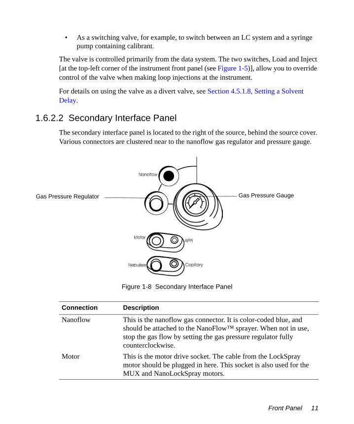
3. To run in LockSpray mode ensure that LockSpray is enabled by Clicking Options on the Instrument Shortcut bar to open the options dialog box (Figure 2-3).
Opening MassLynx 27
Figure 2-3 The Options Dialog Box
4. Select Lock Spray.5. Click OK
2.3 Using the Tune Window
The Tune window is the instrument control interface, it is used for the following.
• Tuning the instrument• Turning gases on and off• Monitoring vacuum pressures• Monitoring Acquisitions• Calibrating the instrument for accurate mass
The Tune window Consists of a peak display window and 3 tabs of parameters viewable by selecting the relevant tab. These are:
• The Source tab• The Transfer tab
28 Basic Introduction to Instrument Operation

• The Analyser tab
Note: There is also a Diagnostics tab that should only be used by a Waters Field Service Engineers.
After the instrument has been correctly set up by the installation engineer the only settings that will require tuning are those on the Source page.
2.3.1 Obtaining a Mass SpectrumThe LCT Premier has four modes of operation:
• V positive• W positive• V negative• W negative
The purpose of the following tutorials is to show you how to get a mass spectrum from the LCT Premier’s four modes of operation.
Note: The Tune window settings for each mode are saved to the same file.
Note: Ensure than analyte is selected if running in LockSpray mode.
2.3.1.1 Infusing Leucine Enkephalin in V Positive Mode1. Ensure that the instrument is in Operate, if not click Press for Operate. The indicator
goes green and the button changes to Press for Standby.
Note: If the LCT Premier has been in Standby for more than 2 hours it should be should be left in Operate for 1 hour to allow the instrument to stabilize.
2. Select Ion Mode > ES+.
3. Click to put the instrument into V mode.
4. Click to switch the API gas on.
5. Set the following parameters on the Source page, typical values are shown in Figure 2-4:• Capillary voltage• Sample Cone voltage• Desolvation Temperature
Using the Tune Window 29

• Source Temperature• Cone Gas.• Desolvation Gas flow
Note: Ensure that you press enter after entering each number.
Figure 2-4 Source Page Settings: Electrospray Positive - V Mode
6. Click to open a drop down list of syringe types.7. From the drop-down menu select the appropriate syringe type e.g, Hamilton 250 µL.8. Load the Syringe with leucine enkephalin (m/z 556) 50 pg/µL (50:50
acetonitrile:water 0.1% formic acid) and click to switch the syringe on.9. Enter a syringe rate of 10 µL/min. This ensures a uniform, continuous spray that
will last for a relatively long period.10. Select Peak Display > Setup Scope to open the Tuning Setup dialog box. Ensure the
values match those in Figure 2-5.
30 Basic Introduction to Instrument Operation

Figure 2-5 Tuning Setup Dialog Box
Note: It may take a while for the sample to appear in the peak display window as any dead volume will need to be cleared first.
Note: If using ACQUITY UPLC™ fast scan times are required. Set the Scan Time (s) to 0.04 and the Inter Scan Delay to 0.01. This will give 20 scans/s.
Assuming that the probe is spraying the peak display window will be showing some response.
11. Click and drag across the peak display to zoom in on the leucine enkephalin peak.
Note: Clicking will return the display to the default setting.
12. Adjust the Capillary and Sample Cone voltages up or down to vary the peak height and shape. With a little patience, the peak display should resemble that shown in Figure 2-6.
Using the Tune Window 31

Figure 2-6 Peak Display
Note: The parameters on the Transfer and Analyser pages should not require changing. Typical settings for these pages are shown in Section D.3, Tune Window Parameters.
13. Select File > Save As to save the tune settings and enter an appropriate name.
2.3.1.2 Infusing Leucine Enkephalin in W Positive Mode.1. Set up the leucine enkephalin infusion as described in Section 2.3.1.1.
2. Click to put the instrument into W mode.3. Set the Source page parameters as shown in Figure 2-7.
32 Basic Introduction to Instrument Operation

Figure 2-7 Source Page Settings: Electrospray Positive - W Mode
Note: The parameters on the Transfer and Analyser pages should not require changing. Typical settings for these pages are shown in Section D.3, Tune Window Parameters.
4. Select File > Save.
Note: The tune settings for W positive mode are appended to the tune file saved in Section 2.3.1.1.
2.3.1.3 Infusing Raffinose in V Negative Mode1. Select Ion Mode > ES-.
2. Click to select V mode.3. Set up the syringe as described in Section 2.3.1.1 and infuse a solution of raffinose
(m/z 503) 50 pg/µL at 10 µL/min.4. Set the Source page parameters as shown in Figure 2-8.
Using the Tune Window 33

Note: The parameters on the Transfer and Analyser pages should not require changing. Typical settings for these pages are shown in Section D.3, Tune Window Parameters.
Figure 2-8 Source Page Settings: Electrospray Negative - V Mode
5. Select File > Save.
Note: The tune settings for V negative mode are appended to the tune file saved in Section 2.3.1.1 and Section 2.3.1.2.
2.3.1.4 Infusing Raffinose in W Negative Mode1. Set up the raffinose infusion as described in Section 2.3.1.3.
2. Click to put the instrument into W mode.3. Set the Source page parameters as shown in Figure 2-9.
34 Basic Introduction to Instrument Operation

Figure 2-9 Source Page Settings: Electrospray Negative - W Mode
Note: The parameters on the Transfer and Analyser pages should not require changing. Typical settings for these pages are shown in Section D.3, Tune Window Parameters
4. Select File > Save.
Note: The tune settings for W negative mode are appended to the tune file saved in Section 2.3.1.1, Section 2.3.1.2, and Section 2.3.1.3.
2.3.2 Setting the Correct Mass RangeThe mass range of the instrument is determined by the pusher settings. These are found on the Analyser page of the Tune window (Figure 2-10).
Using the Tune Window 35

Figure 2-10 Pusher Settings
If these are set to Auto, then the software determines the correct settings from the range being scanned. Selecting manual enables you select any settings or from the drop-down list predetermined ones for a given mass range.
Note: The TDC inhibit should be set to the pusher width.
2.3.3 Acquiring Data from the Tune Window1. Click Acquire to open the LCT Premier Tune Acquire dialog box opens
(Figure 2-11).
Table 2-1 Automatic and Manual Mass Ranges
Acquisition High Mass V Mode W mode
Pusher Interval (µS)
Pusher Interval (µS)
Pusher Width (µS)
≤ 1000 34 62 41001 - 2000 48 87 42001 - 4000 68 124 44001 - 8000 96 174 58001 - 16000 136 255 816001 - 30000 184 255 9
36 Basic Introduction to Instrument Operation

Figure 2-11 LCT Premier Tune Acquire Dialog Box
2. Set the parameters as shown in Figure 2-11.
Note: Clicking Origin opens a dialog box that allows you to enter your own details and details of the sample.
3. Click Start. The LCT Premier begins to Acquire data and save it to disk.
Monitoring the AcquisitionYou can follow the progress of your data acquisition can be followed in both Spectrum and Chromatogram. See the MassLynx User’s Guide for further details on both Spectrum and Chromatogram.
Chromatogram Real-Time Update
1. From the main MassLynx window select Chromatogram from the Sample List menu bar to open Chromatogram.
Using the Tune Window 37

Figure 2-12 Chromatogram Display During Real-Time Update
2. Click in the menu bar to update the chromatogram display as the acquisition proceeds.
Spectrum Real-Time Update
1. From the main MassLynx window select Spectrum from the Sample List menu bar to open Spectrum.
Figure 2-13 Spectrum during Real Time Update
38 Basic Introduction to Instrument Operation

2. Click in the menu bar to update the chromatogram display as the acquisition proceeds.
Note: Spectrum will show each new scan. You will notice that the molecular weights will vary slightly for each scan.
2.3.4 Checking the ResolutionWhile there may be a beam showing in the peak display, a single peak needs to be Tuned to give a resolution of at least 5000 for V mode and 10,000 for W mode, for the LCT Premier to perform to its specification.
Use the following equation to calculate the resolution.
To Check the Resolution
1. Acquire data as described in Section 2.3.3, Acquiring Data from the Tune Window.2. Click Start.3. Open Chromatogram from the MassLynx Sample List menu.
4. Click in the menu bar.5. Combine data from at least 30 scans. On completion the Spectrum window will
open
Note: See the MassLynx User’s Guide for details on how to use Chromatogram, Spectrum and Combine.
6. In the Spectrum window Zoom in on the main peak at 556 Da.
Note: Ensure that a grid is shown on the Spectrum. Select Display > View to open the Spectrum Display dialog
Note: Select Display > Peak Annotation to open the Spectrum Peak Annotation dialog box and ensure that 4 decimal places are entered.
Resolution Mass( ) PeakWidthHalfHeight( )÷=
Using the Tune Window 39

7. With the aid of the grid right-click and drag the mouse across the width of the peak at half height. The width is show in the bottom-left corner of the Spectrum window (Figure 2-14).
Figure 2-14 Combined Spectrum of Leucine Enkephalin Showing Peak Width at Half Height
8. Calculate the resolution as follows:.
In this case, it is quite clearly adequate and above 5000.
If the resolution is not achieved, optimization of transfer and /or analyser parameters may be necessary. This should only be done by a person who has the necessary training.
Note: With experience you can estimate the resolution from the Peak Display on the Tune window.
Note: If a resolution of 5000 for V mode or 10,000 for W mode cannot be achieved then you should contact Waters Technical Support.
Resolution 556.2214 0.0899÷ 6187= =
40 Basic Introduction to Instrument Operation

Chapter 3 Calibration
Before using the LCT Premier for mass accuracy work the instrument requires calibrating. It is recommended that the calibration is checked regularly with an appropriate quality control. A new calibration should be performed after cleaning, maintenance and changing the Lteff value.
The LCT Premier has several wizards that aid in instrument setup and a simple to use calibration program. Use these in the following order:
1. Nominal Mass Wizard (Section 3.1)2. MCP gain Wizard (Section 3.3)3. Calibration (Section 3.4)4. Deadtime Correction Wizard (Section 3.5)
Note: A calibration needs to be done for each mode of operation. Each calibration is saved to the same file.
3.1 Nominal Mass Measurement
Nominal mass measurement is achieved by adjusting the Lteff factor, a term that quantifies the difference between the indicated and actual mass.
Lteff is the effective length of the flight tube and it must be set to give at least nominal mass accuracy. The LCT Premier has a wizard that calculates the Lteff value for you and enters the value into the Acquisition Setup dialog box.
1. From the Tune window select Settings > Acquisition Setup to view the current Lteff setting in the Acquisition Setup dialog box (Figure 3-1). The default setting is 1081.
Nominal Mass Measurement 41

Figure 3-1 Acquisition Setup Dialog Box
2. Infuse a solution of leucine enkephalin (see Section 2.3.1.1). The main peak’s mass will vary slightly from what you expect. In Figure 3-2 it is 555.9 rather than 556.3.
Figure 3-2 Peak Display Before Running the Nominal Mass Wizard
42 Calibration

3. Select Wizards > Nominal Mass Measurement to open the Nominal Mass Measurement Wizard.
4. Select Next5. Select Leucine Enkephalin [M+H]+ from the list of reference compounds.
Note: Choose User Defined Reference to define your own reference compound.
Nominal Mass Measurement 43

6. Click Next. The wizard asks you to infuse leucine enkephalin.7. Make sure that a leucine enkephalin infusion is set up.8. Click Next. The wizard scans the mass range to find the relevant reference peak.
After several seconds, the wizard centers on the peak, and displays the new Lteff setting.
Note: In W mode the Lteff setting is approximately double that shown here.
9. Click Next to accept the new setting. The peak display will now be more accurate (Figure 3-3).
44 Calibration

Figure 3-3 Peak Display After Running the Nominal Mass Measurement Wizard
10. Click Finish to close the wizard.11. Select File > Save to save the new setting to the tune file.
3.2 TDC Settings
The TDC settings are found in the Acquisition Setup dialog box (Figure 3-4).
From the Tune window select Settings > TDC Setup to open the Acquisition Setup dialog box.
TDC Settings 45

Figure 3-4 Acquisition Setup Dialog Box
Parameter Description
Centroiding ParametersCentroid Threshold
Any peak above this value in height (counts) will be classed as ions and a centroid will be produced
Minimum Points Any peak above this value in width (bins) will be classed as ions and a centroid will be produced.
NP Multiplier Used in deadtime correction calculations. A normal value is 0.7.This value can be entered manually but is also updated automati-cally when the DDTC wizard is run (see Section 3.5.1 on page 57).
Resolution Used in deadtime correction calculations. A normal value is >5000 for V mode and >10,000 for W mode but varies according to instrument resolution.This value can be entered manually but is also updated automati-cally when the DDTC wizard is run (see Section 3.5.1 on page 57).
TDC SettingsTrigger Threshold
The size of the signal needed to trigger the TDC (start the clock). The start signal is derived from the pusher voltage itself, and a typical value is 700 mV. This voltage may be different in nega-tive ion mode.
Signal Threshold This is the size of pulse needed to register as being an ion, which stops the clock. It is usually set at 70 mV.
46 Calibration

3.3 MCP Setup Wizard
This ensures that the correct voltage is applied to the micro-channel plate (MCP) optimizing ion detection and minimizing potential electronic artefacts.
1. Select Wizards > MCP Gain to open the MCP Setup Wizard.
Data Threshold This parameter should normally be set to zero. Setting to 1 will cause all peaks in the spectrum with one count to be thresholded out.
Nominal Mass MeasurementLteff This is used to make the TOF mass measurement nominally
correct without a calibration. The default value for V mode is 1081, for W mode it is 2225.This value is set when running the Nominal Mass Wizard (see Section 3.1 on page 41).
Veff Effective flight tube voltage, used for setting up the non-cali-brated mass scale. The value for V mode is 5630 and W mode it is 7200. These values should not be changed.
DXC Temperature CompensationDrift (ppm/oC) Sets the size of correction to be applied to mass measurements to
compensate for the effect of temperature drift.Note: This is not active when real-time lockmass correction is in use.
Parameter Description
MCP Setup Wizard 47

2. Select a suitable reference compound. In this example it is leucine enkephalin.
3. Click Next.4. Following the wizards instructions infuse a solution of 200 pg/µL of leucine
enkephalin.
48 Calibration

5. Click Next. The wizard centers on the peak and counts the number of ions. If there are too few or too many, an error page will appear describing how to adjust the ion count.
6. Adjust the ion count up or down until it falls within the specified range. When this happens the Intensity Check page appears.
MCP Setup Wizard 49

7. Click Next. The wizard alters the MCP voltage until it finds the optimal setting.
8. When enabled click Next to go to the next page. The final page of the Wizard is displayed showing the optimum MCP voltage.
9. Click Finish to accept the value and close the wizard.
50 Calibration

Note: The MCP parameter setting of the Analyser tab of the Tune window is updated.
3.4 Calibrating for Accurate Mass
The purpose of the following is to show you how to calibrate the instrument using sodium formate over a mass range of 100 - 1000 Da.
1. Infuse a solution of sodium formate (see Section 3.4.1 for preparation details).2. De-tune using the probe adjuster and/or the capillary voltage to obtain less than
200 counts per second (cps).
Figure 3-5 Settings and Peak Display for Calibration
Note: If the ion count is above 300 cps, then deadtime distortion will occur. Run the Deadtime Correction wizard (Section 3.5) to correct for this.
Calibrating for Accurate Mass 51

Note: To calculate cps, divide the peak height (shown on the peak display) by the scan time. The Scan time value appears in the Tuning Setup dialog box (see Section D.1.5)].
3. Select Calibration > Calibrate to open the calibration window.4. From the calibration window select File > Open and load Uncal.cal from the Open
dialog box (Figure 3-6) to remove any previous calibration.
Figure 3-6 Calibration Window with Uncal.cal Loaded
5. Select Edit > Calibration Parameters.6. Set the parameters as shown, and click OK.
52 Calibration

Figure 3-7 Calibration Parameters Dialog Box
7. From the Calibration window, select Edit > Tof Mass Measure Parameters to open the Mass Measure dialog box (Figure 3-8).
8. Set the parameters as shown, and click OK.
Figure 3-8 Mass Measure Dialog Box
Calibrating for Accurate Mass 53

9. In the Calibration window click to view the list of calibration reference files, and select NaFormatePosES.ref.
10. Click to open the Automatic Calibration dialog box (Figure 3-9).
Figure 3-9 Automatic Calibration Dialog Box
11. Click Acquisition Parameters to open the Calibration Acquisition Setup dialog box (Figure 3-10)
Note: Calibration Parameters will open the Calibration Parameters dialog (Figure 3-7).
12. Set the Acquisition Parameters as shown in Figure 3-10.
Figure 3-10 Calibration Acquisition Setup Dialog Box
13. Click OK to close the dialog box.
54 Calibration

14. Click OK in the Automatic Calibration dialog box to start acquiring a minutes worth of data.
15. When the calibration is complete the data appears in a new Calibration window (Figure 3-11).
Figure 3-11 Calibration Window Showing Residual Errors
Note: As a general rule, the residual (in mDa) on each individual calibration point should be less than 1.5 mDa. Ideally the majority of calibration points will have residuals of less than 0.5 mDa. A measure of the 'fit' of the calibration line to the experimental data is given in the error of the residual.
Note: The mean residual should be less than 0.5 mDa.
Note: Outliers can be removed from the calibration curve by right-clicking the outlying peak in the reference file spectrum and right-clicking the associated peak on the data file spectrum.
Caution: Always save the calibration with a new name. Do not overwrite Uncal.cal.
Calibrating for Accurate Mass 55

16. Select File > Save As to save the calibration. The details of the calibration will appear in the Calibration window.
Note: It is good practice when saving a calibration to use the date as the filename.
Figure 3-12 Calibration Window Showing Saved Calibration Details
17. Repeat the calibration as desired for all the other modes.
Note: Each calibration for each mode is appended to the same file. Figure 3-12 shows calibration details fro V+, V-, W- and the current mode W+.
3.4.1 Calibration SolutionThe sodium formate calibration solution produces cluster ions (i.e., multimers) of sodium and formic acid in electrospray mode. When compared to other similar calibration solutions such as sodium iodide and caesium iodide, this calibration solution has a more even distribution of ion intensity and a smaller difference in mass between ions.
The distribution of higher mass cluster ions is governed mainly by the concentration of formic acid in the solution and dilution may result in the disappearance of the higher mass ions.
The instrument calibration produced from the sodium formate calibration solution is superior to sodium iodide solution over shorter mass ranges (e.g. 100 to 1000 m/z or 100
56 Calibration

to 600 m/z) because there are a greater number of calibration points and consequently there is less chance of an interpolation error when a high-order polynomial is fitted.
Preparing the Sodium Formate SolutionThe target solution constituent concentration is 0.05 M sodium hydroxide + 0.5% formic acid in 90:10 2-propanol:water.
1. Take 1 mL of formic acid and add to 9 mL of water to produce a 10% formic acid aqueous solution. Label this as Formic Acid Solution.
2. Add 500 µL of 0.1 M sodium hydroxide and 500 µL of Formic Acid Solution to 9 mL of 90:10 2-propanol:water solution. Label this as Sodium Formate Solution 1.
3.5 Deadtime Correction
The instruments data acquisition system is a time-to-digital converter (TDC). This is an ion counting system that generates a mass spectrum by storing the arrival times of ions in a histogram memory. After the arrival and registration of an ion by the TDC, a minimum time interval elapses before a subsequent ion arrival can be registered. This is called the ‘dead time’ of the TDC and is of the order of 5 nanoseconds.
At high ion currents some of the ions generated are not registered, leading to a shift to lower mass centroids, with consequently lower measured areas on reported peaks. However, MassLynx incorporates a correction facility, the Digital Deadtime Correction Wizard (DDTC), which allows for accurate mass measurements to be achieved over a large range of ion currents. The DDTC wizard automatically calculates the NP multiplier value.
3.5.1 Digital Deadtime Correction WizardNote: Before running the DDTC wizard. Run, the Nominal Mass Accuracy Wizard (see Section 3.1) to calculate the Lteff value. This should be done in V and W modes. The example shown here is in V mode.
1. From the Tune window select wizards > Digital Dead Time Correction to open the DDTC wizard.
Deadtime Correction 57
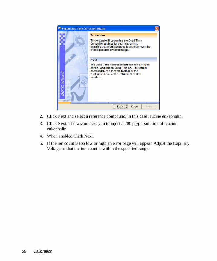
2. Click Next and select a reference compound, in this case leucine enkephalin.3. Click Next. The wizard asks you to inject a 200 pg/µL solution of leucine
enkephalin. 4. When enabled Click Next. 5. If the ion count is too low or high an error page will appear. Adjust the Capillary
Voltage so that the ion count is within the specified range.
58 Calibration

6. When the ion count is within the specified required the Intensity Check page appears.
7. Click Next to go to the following page.8. The wizard now counts down to calculating the Np multiplier value and the
resolution.
Deadtime Correction 59

9. The wizard will then display the results. In this case the resolution is 5397 and NP multiplier is 0.7.
10. Click Next to accept the values. 11. Click Finish to close the Wizard.
The wizard updates the Resolution and NP Multiplier value which appear in the Acquisition Setup dialog box (Figure 3-13)
.
Figure 3-13 Acquisition Setup Dialog Box After Running the DDTC Wizard
60 Calibration

Chapter 4 Advanced Operation
4.1 Applying a Single-Point Lock Mass Correction
Temperature variations in the environment and in the instrument power supplies can cause drifts in measurements of a few hundred parts per million (ppm) over the course of a day. For accurate mass work, the instrument should be kept in OPERATE at all times to enable stabilization of the power supplies. You can compensate for instrument drift by applying a single point lock mass correction. With the LCT Premier this is done using the integral LockSpray reference probe.
4.1.1 Using LockSpray with a Sample List AcquisitionNote: Two syringe pumps are required to perform this procedure.
1. Select Ion Mode > ES+.
2. Click to select W mode.3. Using the same Tune window settings as those in Section 2.3.1.1 on page 29:
a. Infuse a solution of 50 pg/µL of leucine enkephalin at 10 µL/min into the reference sprayer. View the ion beam by selecting Reference from the Tune window.
b. Infuse a solution of 50 pg/µL of raffinose at 10 µL/min into the analyte sprayer. View the ion beam by selecting Analyte from the Tune window.
Note: Raffinose forms a sodium adduct in positive mode at m/z 527.
4. In the Sample List in the main MassLynx window, enter values in the File Name and File Text columns as shown in Figure 4-1.
Applying a Single-Point Lock Mass Correction 61

Figure 4-1 Sample List
5. Right-click in the MS File column and select Edit form the pop-up menu to open the MS Method Editor.
6. Click MS Scan to open the TOFMS Scan dialog box. Enter the values as shown in Figure 4-2 and then click OK.
Figure 4-2 TOFMS Scan Dialog Box
7. From the MS Method Editor select File > Save As. Choose a suitable name, e.g., LockSprayMS.
62 Advanced Operation

8. Select File > Exit to return to the Sample List.9. Right-click in MS File column and select Browse from the pop-up menu. 10. Select the method file you have just saved.
11. Click to start the acquisition. This will open the Start Sample List Run dialog box (Figure 4-4). Leave the settings as they are and click OK.
Figure 4-3 Start Sample List Run Dialog Box
12. Check that both the reference and analyte samples are being acquired:a. Select Chromatogram from the Sample List.b. Select Display > TIC to open the TIC Chromatogram dialog box (Figure 4-4).
Figure 4-4 TIC Chromatogram Dialog Box
Applying a Single-Point Lock Mass Correction 63

c. Select both traces to display and select for Real-Time Update (see Figure 4-5).
Note: Figure 4-5 has been annotated to distinguish between each trace.
Figure 4-5 Reference and Analyte Spray Data in the Chromatogram Window
13. Double-click in a region of each chromatogram to open up a spectrum for each spray in the Spectrum window (Figure 4-6).
Note: Figure 4-6 has been annotated to distinguish between each trace.
64 Advanced Operation

.
Figure 4-6 Analyte and Reference Spray Data in the Spectrum Window.
Calculating the Mass Accuracy1. Return to the Chromatogram window and Select Process > Combine Spectra to
open the Combine Spectrum dialog box (Figure 4-7).
Figure 4-7 Combine Spectrum Dialog Box
Applying a Single-Point Lock Mass Correction 65

2. Right-click and drag across at least 30 seconds of data. The scan numbers will appear in the Average text box.
3. Click OK to open the combined spectra in the Spectrum window (Figure 4-8).
Figure 4-8 Combined Spectrum in Spectrum Window
4. Use the following equation below to calculate the ppm error.
Where:
mind is the indicated massmact is the actual mass
The ppm error is indicated in Figure 4-8.
ppmErrormind mact–
mact--------------------------- 106×=
66 Advanced Operation

4.2 Dynamic Range Enhancement
The LCT Premier has hardware and software improvements that extends the dynamic range of the instrument to four orders of magnitude. This is called Dynamic Range Enhancement (DRE). This is achieved by applying a high voltage to a Z-focusing lens, reducing the intensity of ions passing into the TOF.
Note: The installation engineer optimizes lens performance No further adjustment is necessary.
Changing the lens manually from normal to attenuated, decreases the ion intensity approximately 40 times (20 - 60 times is acceptable). DRE only functions in a real-time centroid acquisition, and as such the DDTC parameters must be correctly set (see Section 3.5 on page 57).
The DRE functionality is a software driven process that replaces saturated data in a spectrum with unsaturated data acquired when the ion beam has been defocused by the Z-lens. The process is driven by the appearance of individual peaks in a spectrum which have ion intensities that exceed the upper limit of the deadtime correction model.
For example in a non-DRE centroid acquisition individual ion peaks which have intensities that exceed the upper limit of the deadtime correction model will be flagged with a question mark. To see the '?' symbol in the spectrum you must enable the peak flag display by ticking the peak flags box in the Spectrum Peak Annotation dialog box.
Note: The observed cps at which the peak flag appears is influenced by both the optic mode (V or W) and the upper m/z range of the acquisition.
Typically in a V mode acquisition with a 1000 m/z upper limit, spectral peaks with intensities of greater than approximately 30,000 cps will be replaced with the corresponding defocused (i.e. non-saturated) peaks. This process is referred to as “peak stitching”. Defocused peaks, that are stitched in, are magnified in intensity by a defined magnification factor equal to the decrease in ion intensity attenuated by the Z-lens. Therefore, if approximately 30,000 cps is the upper limit for a V mode 1000 m/z upper mass range experiment, the corresponding stitched in data will have an upper limit of approximately 1.2 x 10⁶ when the magnification is a factor of 40.
Note: Stitched in peaks will be flagged with the '?' when they exceed the upper limit of the deadtime correction model i.e. >1.2 x 10⁶ for the above example
Figure 4-9 shows the two chromatograms of the same sample overlaid on each other. One sample was run with DRE and the other without. The peak without DRE saturates the detector and has a flat top. The normal peak shows where DRE data has been stitched in.
Dynamic Range Enhancement 67

Figure 4-9 Chromatogram Showing Peak With and Without DRE
If the Z-focus lens is not enabled then the following characteristics of saturation will be seen:
• Incorrect isotope distribution• Incorrect accurate mass• Detection of “ringing” artefacts
Note: These characteristics can also be observed in stitched in data if the ion intensity exceeds the upper limits of the DRE functionality.
Figure 4-10 shows 2 spectra, one with DRE and the other without. Note how the accurate mass has been shifted by 20 mDa and the isotope distribution is incorrect for the saturated spectrum. For the saturated data peaks 1, 2 and 3, are ringing artefacts from the C12 isotope and 4 is from the C13 isotope.
Note: The ion count for the DRE data is 346,000 ions/s, this would never be seen in a non-DRE experiment.
68 Advanced Operation

Figure 4-10 Spectra Showing DRE and Non DRE Data
4.2.1 Dynamic Range Enhancement SettingsSelect Settings > Dynamic Range Enhancement to open the Dynamic Range Enhancement dialog box (Figure 4-11).
DRE
mass shift (-20 mDa)
1
2
34
Stitched in data with <5ppm accuracy
Saturated data showing deadtimeNon-DRE
Dynamic Range Enhancement 69

Figure 4-11 Dynamic Range Enhancement Dialog Box
Setting the Magnification FactorThe Magnification factor for DRE is set with the DRE wizard.
1. Select Wizards > DRE Wizard.
Parameter Description
Magnification Factor The magnification factor can be set manually, or by the DRE wizard and is normally between 20 - 60.
Stitch Window (Da) Enter 0.25 for V mode and 0.1 for W mode. In MassLynx 4.0 SP4, this is set automatically and is not shown.
70 Advanced Operation

2. Click Next.3. Select a suitable reference compound (in this example it is leucine enkephalin).4. Click Next.5. Following the wizards instructions infuse a solution of 200 pg/µL of leucine
enkephalin. In addition, ensure on the Transfer page that Normal is selected for Dynamic Range Voltages and Z-Focus lens is tuned for maximum intensity.
6. Click Next. The wizard centers on the peak and counts the number of ions. If there are too few or too many, an error page will appear describing how to adjust the ion count.
Dynamic Range Enhancement 71

7. Adjust the ion count up or down until it falls within the specified range. When this happens the Intensity Check page appears.
8. Click Next to go to the Attenuated “Z-Focus” lens setup page.
72 Advanced Operation

9. Following the instructions decrease the ion count until it falls within the specified range.
10. Click Next, when enabled, to go to the following page.11. The wizard now counts down to calculating the magnification factor.12. The wizard then displays the results.
In this case a magnification factor of 28 has been calculated.
Dynamic Range Enhancement 73

13. Click Finish to accept the value and close the wizard.The setting in the DRE Settings dialog box will be updated.
4.2.2 Using DRE
Setting Up the Reference CompoundThis procedure is only valid for V mode and 1000 m/z upper mass limit.
Note: The instrument should be tuned through the reference sprayer while mobile phase is still spraying through the analyte probe.
1. From the Tune window select Reference from the LockSpray frame of the Source page.
2. Optimize a solution of leucine enkephalin (200 - 1000 ng/µL) to give an ion count for the C12 isotope that is in the upper range of the DDTC model e.g. 20,000 cps. If the question mark appears the ion intensity is too high. The intensity of the reference ion can be controlled by tuning of the reference scan cone voltage in the MS Scan parameters.In MassLynx 4.0 SP4 and above, tune on the C13 isotope.
3. Acquire centroid data from the Tune window using the parameters shown in (Figure 4-12).
74 Advanced Operation

Figure 4-12 Acquisition Parameters for Reference Compound
4. Select Spectrum from the MassLynx Sample List menu to open the Spectrum window.
5. Select from the Spectrum menu bar to turn on Spectrum Real-time update.6. Change the Z-focus lens, on the Tune window’s Transfer page, between normal and
attenuated, and observe the different intensities.
Note: The intensities of the normal and attenuated reference ions should be approximately 20,000 and 500 cps respectively. If the intensity of the attenuated reference ion is too low the lock mass correction of “stitched” in data may be statistically more variable.
Performing a DRE ExperimentNote: Depending on the version of MassLynx 4.0, either SCN 496 or SP4, there are slight variations in setting up the experiment. In SP4 a dual lock mass is used. In the example shown here this is done with the C12 and C13 isotopes of leucine enkephalin, where the C12 isotope is used in attenuated mode and the C13 isotope in normal mode.
1. Select MS Method from the MassLynx Instrument shortcut bar to open the MS Method Editor (see Section 4.5 on page 87 for further details)
Dynamic Range Enhancement 75

2. Select to create a new MS Scan function. In SCN 496 specify the parameters shown in Figure 4-13.
Figure 4-13 MS Scan Parameters for DRE Experiment: MassLynx 4.0 SCN 496
In MassLynx SP 4 set the parameters shown in Figure 4-14.
Note: The C13 Lock Mass initially needs to be specified. Type in a name followed by the mass, for leucine enkephalin this is 557.2804.
Note: In the standard mode, the height of the C12 attenuated Lock Mass peak will have ion counts above the upper limit of the deadtime correction model. If peak flags are enabled the peak will be flagged with “?”. However, when defocused this will not be the case. The dual lock mass function improves the mass accuracy of stitched in data because of better ion statistics for the attenuated lock mass.
76 Advanced Operation

Figure 4-14 MS Scan Parameters for DRE Experiment: MassLynx 4.0 SP4
3. Save with a suitable name (i.e. DRE).4. Create an identical experiment but with Normal Dynamic Range selected.5. Save with a suitable name (i.e non-DRE).6. Setup an HPLC system according to Section 4.3 (see also MassLynx Inlet Control
Guide).7. Create a Sample List of six samples, using five dilutions of sulphadimethoxine in
70:30 acetonitrile:water (1 pg/µL, 10 pg/µL 100 pg/µL 1000 pg/µL and 10,000 pg/µL) (Figure 4-15). Ensure:• The correct inlet file is selected in the Inlet File column.• That the correct method files created in step 1 to step 5 are entered in MS File
column.• The bottle numbers correspond to the correct vial positions in the autosampler.
Dynamic Range Enhancement 77

Figure 4-15 DRE Sample List
Note: The sixth sample is the 10,000 pg/µL sample injected again but with DRE not selected.
8. Click to open the Start Sample List Run dialog box.9. Click OK to start the acquisition.
Note: The DRE software is self-triggering. When a centroid intensity is detected that exceeds the DDTC model, the saturated peak will be replaced with a peak from a defocused scan.
10. When the acquisition has finished:• View the chromatograms for each sample. The ion counts should become
progressively greater with the peaks. Sample six, where DRE is not enabled, will show a flat-topped peak similar to that in Figure 4-9.
• View the spectra for each sample. The mass for samples 1 through 5 should be accurate to <5 ppm. For Sample 6, where DRE is not operating, a deadtime mass shift of >20 mDa will be evident.
Note: In a DRE experiment you cannot view the attenuated analyte and reference data. Therefore DRE experiments will have half the displayed number of scans as a corresponding non-DRE experiment
4.3 Setting Up an LC Inlet
The LCT Premier will predominantly be used with an LC system, this is setup using the Inlet Configuration Wizard. Further details on the Inlet Method Editor can be found in the MassLynx Inlet Control Guide.
1. From the MassLynx Status Shortcut bar select Inlet Method from the to open the Inlet Method Editor (Figure 4-16).
78 Advanced Operation

Figure 4-16 Inlet Method Window With No Inlets Installed
2. Select Tools > Instrument Configuration to open the Inlet Configuration dialog box.
Figure 4-17 Inlet Configuration Dialog Box
Setting Up an LC Inlet 79

3. Click Configure to open the Inlet Configuration Wizard.4. Click Next to open the Select Pump page and then choose the appropriate Pump.5. Click Next to open the Select Autosampler page and then choose the appropriate
Autosampler6. Click Next to open the Select Detector page and choose the appropriate Detector7. Click Next to go to the Configure GPIB page. Typical settings for the inlets chosen
are shown in Figure 4-18.
Note: For Agilent devices the Configure HPIB page is displayed
Figure 4-18 Configure GPIB Page
Note: GPIB settings should not be changed if set by a Waters Field Service Engineer.
8. Click Next to open the Configuration Successful page9. Click Finish10. From the Inlet Configuration dialog box (Figure 4-17) click Events & Triggering to
open the Events and Triggering Wizard (Figure 4-19). Use this wizard to configure input and output events and triggering methods for certain pumps and detectors.
80 Advanced Operation

Figure 4-19 Events and Triggering Wizard: Welcome Page
11. Click Next to open the Choose Events page (Figure 4-20).12. Click the Event In that corresponds to the HPLC cable connection on the back panel
of the LCT Premier (see Section 1.7, Rear Panel).13. If required, select an Event Out.
Setting Up an LC Inlet 81

Figure 4-20 Choose Events Page
14. Click Next to open the Choose Triggering Method page (Figures 4-21).
Figure 4-21 Choose Triggering Method Page
82 Advanced Operation

15. Click Trigger by Software and then click Next to open the Configuration Successful page.
Note: Triggering allows the definition of how the LC or detector run is triggered, whether by contact closure or software.
16. Click Finish to close the Events and Triggering Wizard.17. Click Finish to close the Inlet Configuration window and return to the Inlet method
Editor.
4.4 Shutting Down for the Day
At the end of a day’s work there are a number of instrument settings that should be turned off or changed to suitable ‘static’ values. This is done in two ways:
• Manually Shutdown as described in Section A.2.2, Overnight Instrument Shutdown.• Automatically Shutting down as described in Section 4.4.1, Automatically Shutting
Down for the Day. Further details on the Shutdown Editor can be found in Section A.3.1, The Shutdown Editor.The Shutdown Editor allows you to initiate a defined shutdown procedure following the termination of a sample batch or on a system error e.g. a LC failure that registers an error in MassLynx.
Note: Shutting the instrument down really means turning off the source parameters and at no time should you consider turning the instrument out of Operate mode or turning the TOF power supply down from its operating value. You should ensure that the instrument is left in a stable electronic state, as this will greatly aid the acquisition of good quality data.
4.4.1 Automatically Shutting Down for the Day1. Select Edit Shutdown or Startup from the MassLynx Instrument Shortcut bar to
open the Shutdown Editor (Figure 4-22).
Shutting Down for the Day 83

Figure 4-22 Shutdown Editor
Note: At the bottom of the main MassLynx window the status bar indicates the current shutdown status of the instrument e.g. Shutdown Disabled or Shutdown Enabled.
2. Select the Enable shutdown after batch check box and click Browse to insert the correct shutdown file.
3. Click on the Auto Control Tasks tab to show the user-defined shutdown parameters (Figure 4-23).
84 Advanced Operation

Figure 4-23 Auto Control Tasks
4. In Figure 4-23 three separate commands were entered into the control tasks list:– The LC Pump Off task is first with a post delay set at 180 seconds. This task is
performed first and 3 minutes is allowed to pass before the next task is performed. The purpose of this delay is to allow sufficient time for any residual solvent vapors to be removed from the source.
– The Tune file task is then performed. The task loads a user-defined tune file to be automatically loaded into the Tune window. The purpose of this file is to change the source and desolvation heaters to appropriate 'shutdown' values. See “Creating a Tune File for Shutdown” on page 86 for further details.
– The Source Gas Off task is specified with a 180-second pre delay. This 3 minute period allows the source time to cool after the source heating settings have been reduced before the API gas is turned off.
5. Close the Shutdown Method window.
Note: The MassLynx status bar indicates Shutdown Enabled.
6. Run your samples. After the final sample has been acquired, the Shutdown method will run automatically.
Note: When you return to the instrument after the automatic shutdown, you should disable the shutdown method until you want to use it again, i.e., at the end of the day. If you do not disable the shutdown method, the instrument may shut down at an inappropriate time.
Shutting Down for the Day 85

Creating a Tune File for Shutdown
As part of shutting down the instrument, specify in the shutdown method a suitable tune file that matches the file you are using for the acquisition but with different settings for the capillary voltage and the source and desolvation temperatures. This will ensure the instrument retains all the vital tune file settings which determine the TOF parameters and is ready to use following the shutdown period.
1. Save the tune file under suitable name (e.g. shutdown.ipr) with the following settings shown in Table 4-1.
Note: This file must be in the C:\masslynx\shutdown directory. You can either save the file in this directory or you can save it in the Acqudb folder of the project you are currently working in and use the Windows Explorer to copy the file into the C:\masslynx\shutdown directory.
2. Reload the tune file you will be using to acquire the data and ensure that the capillary and temperature settings are correct.
4.4.2 Starting UpThe following procedure should be carried out after the Instrument has been shutdown overnight.
1. Check that the gas supply is adequate and at the correct head pressures.2. Turn on API gas using the Tune window toolbar.3. Check flow rates for Desolvation, Nebuliser and Cone gas.4. Increase the Source and Desolvation temperatures to suitable values for liquid flow
rate and composition.5. Change the Capillary Voltage to an appropriate value.6. You are now ready to start an infusion or LC experiment.7. Remember to check for adequate desolvation during the experiment and alter gas
flow or temperatures accordingly.
Table 4-1 Settings for Shutdown Tune File
Parameter Setting
Capillary Voltage 0 VSource Temperature 50 °CDesolvation temperature 20 °C
86 Advanced Operation

4.5 The MS Method Editor
4.5.1 Setting Up a MS Scan FunctionA Function List is set up using the MS Method Editor (Figure 4-24). This contains the function that the mass spectrometer uses to scan the instrument during an acquisition.
A Function List is created, saved on disk, and then referenced by name when an acquisition is started.
Figure 4-24 shows a simple Function List containing only one function: Tof MS scan, between 100 and 1000 amu using ES+ ionization. Immediately above the function bar display is a time scale that shows from when the function is active, and for how long it runs. In this case, the function starts after 0 minutes and then runs for 60 minutes.
The currently selected function is highlighted and enclosed in a rectangular frame. If the display shows more than one function, a different function can be selected either by clicking with the mouse or by using the keyboard arrow keys.
The MS Scan Function Editor (Figure 4-25) is used to set up centroid, continuum, and MCA functions.
To set up a MS Scan function:
1. Click the MS Method icon in the MassLynx window to open the MS Method Editor.
Figure 4-24 MS Method Editor
2. On the MS Method Editor, click or select Functions > MS Scan to open the Full Scan Function Editor.
The MS Method Editor 87
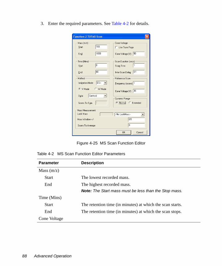
3. Enter the required parameters. See Table 4-2 for details.
Figure 4-25 MS Scan Function Editor
Table 4-2 MS Scan Function Editor Parameters
Parameter Description
Mass (m/z) Start The lowest recorded mass.End The highest recorded mass.
Note: The Start mass must be less than the Stop mass.
Time (Mins)Start The retention time (in minutes) at which the scan starts.End The retention time (in minutes) at which the scan stops.
Cone Voltage
88 Advanced Operation

Use Tune Page When selected, the cone voltage set on the Tune window at the start of the acquisition is used.Note: The cone voltage value cannot be altered during acquisition by typing new values into the Tune window, since the new values are not downloaded during acquisition. This can only be done by acquiring from the Tune window.
Cone Voltage (V) Specifies the cone voltage.Method
Ionization Mode Specifies the ionization mode and polarity to be used during data acquisition.
V Mode Select to acquire data in V mode.W Mode Select to acquire data in W mode.Data Specifies the type of data to be collected and stored on disk
Centroid, Continuum, or MCA (see Section 4.5.1.1).Scans to Sum Enter the number of scans to sum per recorded spectrum in MCA
mode.Scan Duration (secs)
Scan Time Specifies the duration of each scan in seconds.Inter-Scan Delay Specifies the time between a scan finishing and the next one
starting, in seconds. No data are stored during this period.The minimum inter-scan times are as follows:
• Polarity switching 0.3 s• LockSpray 0.1 s• All other experiments 0.01 s.
Reference ScanFrequency (scans) Enter the frequency at which a reference scan is taken Cone Voltage (V) Specifies the Cone Voltage for the Reference Sprayer.
Dynamic Range Select Extended for DRE.Mass Measurement These parameters are only available when Centroid is selected as
the data type to be collected.Lock Mass Select the Lock Mass from the drop down list of compounds.
Table 4-2 MS Scan Function Editor Parameters (Continued)
Parameter Description
The MS Method Editor 89

4.5.1.1 Types of Data AcquisitionIn the Function Editor, the Data parameter specifies the type of data to be collected and stored on disk. There are three options:
• Continuum. The TDC acquires up to 30,000 complete spectra per second. These spectra are summed in the embedded PC for a time period defined in the experiment function, the "Scan Time". The result is that one complete spectrum is saved to disk per scan. With continuum data peak shape is preserved and resolution can be calculated. Post-processing is required to determine exact mass information. A disadvantage is that file sizes can be very large.
• Centroid. The raw spectra from the TDC are summed for the duration of the scan, and then the data is then converted to "stick" form. This preserves mass and intensity information, but peak shapes are lost. With the use of a lock mass, real-time exact mass is possible, with exact mass data being saved to disk. An advantage is that file sizes are much smaller than with continuum data.
• MCA. "Multi Channel Analysis" data can be thought of as summed continuum, with successive spectra output from the embedded PC being summed in the MassLynx PC according to the "Scans To Sum" parameter in the experiment function. The result is effectively very long scan times and consequently smaller file sizes. This data type is not suitable for time-resolved data.
4.5.1.2 Adding a New Function to the List1. Click one of the toolbar buttons or select the required function from the Functions
menu.The editor for the function type selected opens, showing default values.2. Make any changes required to the parameters and click OK. The new function is
added to the Function List.
4.5.1.3 Modifying an Existing Function in the List1. Select the function in the Function List.
Mass Window +/- Enter the mass window around Lock Mass around which the software will look for the reference compound.
Scans to Average This is the number of scans to produce a rolling average for the Lock Mass.
Table 4-2 MS Scan Function Editor Parameters (Continued)
Parameter Description
90 Advanced Operation

2. Click or double-click on the function. to open the appropriate editor for the function type and allows changes to be made.The Function List display is updated to show any changes.
4.5.1.4 Copying an Existing Function in the List1. Select the function in the Function List.2. Select Edit > Copy.3. Select Edit > Paste. A copy of the function appears in the Function List.4. Modify the parameters as described in Section 4.5.1.3, Modifying an Existing
Function in the List.
4.5.1.5 Removing a Function from the List1. Select the function in the Function List.
2. Click , select Edit > Delete, or press the Del key.
4.5.1.6 Changing the Function Order in the ListFunctions appear in ascending Start Time and End Time order; this order cannot be changed. For functions with the same start and end time, you can change the order in which they are performed as follows:
1. Select the required function.
2. Repeatedly click or until the function is in the required position.
4.5.1.7 Setting the Maximum Retention Time1. Enter the required value in the Total Run Time text box.
2. Click .The ratio of the functions defined is maintained. For example, if two functions are defined, one from 0 to 5 minutes, and the other 5 to 10 minutes, then a Total Run Time of 10 minutes is displayed. If this value is changed to 20, the first function now runs from 0 to 10 minutes and the second from 10 to 20 minutes.
The MS Method Editor 91

4.5.1.8 Setting a Solvent DelayTo set a solvent delay for a Function List, select Options > Solvent Delay on the MS Method Editor to open the Solvent Delay dialog box (Figure 4-26).
No data is stored during the solvent delay period, which means that solvent peaks that would normally be seen eluting on the TIC chromatogram are no longer seen.
Figure 4-26 Solvent Delay Dialog Box
For APCI functions, the APCI probe temperature is set to the value specified in the APcI Probe Temp field for the period of the solvent delay.
To enable the divert/injector valve to be used as a divert valve, select Enable Divert Valve. This diverts the flow of solvent during a solvent delay period either to, or away from, the source for the time period shown in the solvent delay timetable.
Up to four solvent delays can be programmed.
4.5.1.9 Acquiring Analog DataYou can acquire up to eight channels of analog data, which are stored with the data acquired from the mass spectrometer.
Analog channels are typically used to collect data from external units such as UV detectors, which must be connected to the ANALOG CHANNEL connectors described in “Analog Channels” on page 22.
92 Advanced Operation

A reading is made from the external channel at the end of each scan and stored with the data for that scan. The resolution of the chromatography for an analog channel is therefore dependent on the scan speed used to acquire the mass spectrometry data.
To open the Analog Data dialog box (Figure 4-27), select Options > Analog Data on the MS Method Editor.
Figure 4-27 Analog Data Dialog Box
To store data for an analog channel:
1. Select the box(es) for the channel(s) required.
2. Enter a textual description for each selected analog channel.This description is used on the analog Chromatogram dialog box as the channel description. See the MassLynx User’s Guide.
3. Enter an Offset (minutes) to align the external unit with the mass spectrometer.4. Click OK.
4.5.1.10 Saving and Opening a Function ListTo save a Function List file:
1. On the MS Method Editor, select File > Save As to open the Save As dialog box.2. Enter a new file name or select an existing file from the displayed list.3. Click Save.
If the file already exists on disk, confirmation is requested to overwrite the existing information.
4. Click Yes to overwrite the file or No to select a different name.When the editor closes, a prompt is displayed to save any changed Function Lists.
The MS Method Editor 93

To open a saved Function List file:
1. From the MS Method Editor, select File > Open to open a standard Open dialog box.2. Select the name of the Function List file to open, either by typing its name or by
selecting it from the displayed list.3. Click Open.
94 Advanced Operation

Chapter 5 APCI, APPI and ESCi
In addition to electrospray ionization, the LCT Premier also has several other ionization modes all of which require tuning for maximum sensitivity:
• Atmospheric Pressure Chemical Ionization (APCI) (Section 5.1)• Atmospheric Pressure Photoionization (APPI) (Section 5.2)• Dual APCI/APPI (Section 5.4.2)• Electrospray Chemical Ionization (ESCi™) (Section 5.5)
5.1 APCI Operation
5.1.1 Installing the APCI probeNormally, you will have to remove the ESI probe, the LockSpray motor and the reference sprayer from the instrument before fitting the APCI probe.
1. Disconnect the LC system from the ESI probe.2. On the MassLynx window, click Press for Standby and ensure that the adjacent
instrument status indicator turns red.
Note: If the LCT Premier has been in Standby for more than 2 hours it should be left in Operate for 1 hour to allow the instrument to stabilize.
3. Wait for three minutes to allow the desolvation gas flow to cool the probe and source.
4. Click to turn off the nitrogen gas flow.
5. Remove the source cover.6. Disconnect the LockSpray motor cable.
Warning: To avoid burns, take great care while working with the instrument’s source cover removed as the probe and source may still be hot.
APCI Operation 95

7. Withdraw the LockSpray motor and replace with the blank side flange (see Figure 1-9 on page 13).
Note: Check that the probe Interlock Active is not displayed in the bottom right of the Tune window. If it is refit the side flange so that it is flush with the source housing.
8. Remove the reference probe and replace with the blank bottom flange (see Figure 1-9 on page 13).
9. Disconnect the Capillary and Desolvation Heater electrical connections on the instrument front panel (see Figure 1-5 on page 8).
Note: Park the Desolvation Heater connection in the Plug Parking socket on the primary interface panel (see Figure 1-6 on page 9).
10. Disconnect the PTFE tubing at the Nebuliser gas port on the front panel.11. Undo the two thumbscrews securing the probe to the probe adjustment flange.12. Carefully remove the probe from the probe adjustment flange.13. Unfasten the source enclosure door’s securing clips and open the door.
14. Use needle-nose pliers to remove the blanking plug from the corona discharge pin mounting contact. Store the blanking plug in a safe location.
15. Fit the corona discharge pin to the mounting contact. Ensure that the corona discharge pin tip aligns with the sample cone tip (see Figure 5-1).
16. Close the source enclosure door and fasten the securing clips.17. Carefully slide the APCI probe into the hole in the probe adjustment flange. Adjust
the probe tip so that it is approximately half way between the cone apex and the corona pin tip.
18. Secure the probe by tightening the two thumbscrews.19. Connect the probe PTFE tubing to the Nebuliser gas port on the front panel
(see Figure 1-6 on page 9).20. Connect the APCI probe electrical lead to the Probe connection on the front panel.
Warning: To avoid electric shock disconnect the reference probe HV connector from the secondary interface panel.
Warning: To avoid electric shock ensure that the instrument is in standby mode when fitting the corona discharge pin.
96 APCI, APPI and ESCi

Note: The probe adjustment flange electrical lead is not used when the APCI probe is fitted; it is not connected to the Desolvation Heater electrical connection on the front of the instrument in can be parked in the Plug Parking socket on the primary interface panel (see Figure 1-6 on page 9).
Figure 5-1 Corona Discharge Pin
5.1.2 Tuning for APCI Operation
1. Complete the connections between HPLC pump, syringe pump, and APCI probe as shown in Figure 5-2.The column used in this example is a Waters Symmetry C18 2.1 × 100 mm, 3.5 µm.
Warning: To avoid possible high-pressure liquid jet spray, wear safety goggles when making the connections between the HPLC pump, LC column, syringe pump, and APCI probe.
Warning: To avoid the possibility of electric shock, ensure that the instrument is in standby mode before making the connections between the HPLC pump, LC column, syringe pump, and APCI probe.
Corona Discharge Pin
Mounting Contact
APCI Operation 97

Figure 5-2 Pump and Column Connections to the APCI Probe
2. Look through the source’s view port and ensure that the isolation valve lever is fully to the left, indicating that the valve is open.If the lever is in the wrong position:a. Remove the source cover.b. Unfasten the source enclosure door’s securing clips and open the door.
c. Operate the lever.d. Close the source enclosure door and fasten the securing clips.e. Close the instrument’s front access door.
3. If not already running, start the MassLynx software; the MassLynx window is opened.
Warning: The probe and source are liable to be hot. To avoid burns, take great care while working with the instrument’s front access door open.
98 APCI, APPI and ESCi

4. Click the Instrument shortcut bar MS Tune icon to open the Tune window.5. Select Ion Mode > APcI+ to open the APCI+ Source tab.6. Set the Support Gas on the probe to 1.0
Figure 5-3 Tune Window
7. Set the parameters to the recommended values shown in Figure 5-3.
Note: For most compounds Current Mode should be selected so as to maintain a constant current. For some compounds Voltage Mode may provide better results.
8. Click to turn on the nitrogen gas flow.9. On the APCI+ Source tab, observe the Desolvation and Cone gas flows; ensure that
they have stabilized and are correct.10. Check that the APcI Probe Temp (°C) readback shows approximately room
temperature.
APCI Operation 99

Note: If the LCT Premier has been in Standby for more than 2 hours it should be left in Operate for 1 hour to allow the instrument to stabilize.
11. Click Press for Operate and check that the adjacent instrument status indicator turns green.
12. Set the APCI probe temperature to 500°C and check that the readback reaches and stabilizes at this temperature.
13. Set the LC system to run at 1 ml/min14. Turn on the LC system and check that its pressure is stable.15. Allow 15 minutes for the LC column to equilibrate.16. Load the syringe pump with sample. In this example 17 α hydroxyprogesterone
(concentration 1 ng/µL, in 70:30 acetonitrile:water) is used.
Note: For negative ion sulphadimethoxine could be used.
17. Ensure that the correct syringe type has been selected as follows:a. Select Options > Syringe Type to open the Syringe Selection dialog box.b. Select the syringe type currently being used from the drop-down list.
Note: If the syringe type is not listed, click Edit and add the relevant details.
c. Click OK.18. On the APCI+ Source tab, set Syringe, Pump Flow (µL/min) to 10.
19. Observe the 17 α hydroxyprogesterone peak at m/z 331.2 (M+H+) displayed on the Tune window (see Figure 5-4).
20. Starting with the probe tip midway between the cone and the end of the corona pin, use the probe adjuster to maximize the displayed peak intensity.
21. Use the probe adjuster to move the probe tip as far away from the cone as possible, without losing more than 20% of the maximum displayed peak intensity obtained in step 20. This will minimize source contamination.
22. Use the nebulization adjuster on the probe to give the best displayed peak intensity and stability.
23. On the Tune window APCI+ Source tab, optimize the Corona (µA) current to the value giving the maximum displayed peak intensity. Do this by looking for the maximum peak intensity while performing the following steps:a. Starting with a value of 5, decrease the value to 1, in decrements of 1.b. Decrease the value to 0, in decrements of 0.1.
100 APCI, APPI and ESCi

c. Reset the value to 5, and then increase the value in increments of 5.d. Set the Corona (µA) current to the value giving the maximum displayed peak
intensity.
Note: Typical values will be 5 µA for positive ion and 15 µA for negative ion
24. Starting from a value of 0, increase the Cone (L/hr) gas flow in increments of 50. Allow the pressure to stabilize after each adjustment. Set the gas flow to the highest value that does not significantly reduce the peak intensity. This minimizes solvent ion cluster formation.
25. Starting from a value of 15, increase the Sample Cone voltage in increments of 5. Set the cone voltage to the value giving the highest displayed peak intensity. Record this value.
26. Reduce the APcI Probe Temp (°C) to 300, and then increase its value in increments of 50. Allow the temperature readback to stabilize after each adjustment. Set the temperature to the highest value that does not decrease the displayed peak intensity.If the probe temperature is too low, the mobile phase may not be efficiently desolvated. This can result in chromatographic peak tailing.
27. With the Sample Cone, Corona Cone Gas and APcI probe temperature now at their optimum values, the displayed peak should be similar to that shown in Figure 5-4.
APCI Operation 101

Figure 5-4 Tune Window with a 17 α hydroxyprogesterone Peak
5.2 The Combined APPI/APCI Source
5.2.1 APCI ProbeThe APCI probe used in the Combined APPI/APCI Source is the standard probe used in the LCT Premier for APCI operation (see Figure 5.1).
5.2.2 APPI Lamp Drive AssemblyThe APPI lamp drive assembly (Figures 5-5 and 5-6) consists of:
• A UV lamp.• A repeller electrode.• A lamp holder.• A mounting shaft with numbered indexing indents.
102 APCI, APPI and ESCi

• A molded enclosure, housing drive electronics.• An APPI source enclosure side plate.
The APPI lamp drive assembly mounts onto the APPI source enclosure side plate, which in turn mounts onto the side of the instrument’s source enclosure (see Figure 5-7).
Switching the UV lamp on (from the MassLynx™ Tune window, see Figure 5-8) provides a constant photon output. The intensity of incident radiation up the sample molecules is varied by manually adjusting the distance between the lamp and probe tip, using the handle on the APPI lamp drive assembly to move the whole assembly on its mounting shaft. The mounting shaft’s four numbered indexing indents aid in setting this distance.
Figure 5-5 APPI Lamp Drive Assembly and Side Plate
Indexing Indent Identification Numbers
HV Electrical Connection
APPI Electrical Connection
APPI Lamp Drive Assembly
Handle
Thumbscrew
Source Enclosure Door Securing Clip
Securing Screw
Mounting Shaft
Source Enclosure Side Plate
The Combined APPI/APCI Source 103

Figure 5-6 APPI Lamp Drive Assembly showing the UV Lamp and Repeller Electrode
Figure 5-7 APPI Lamp Drive Assembly fitted to the Source Enclosure
Source Enclosure Side Plate
UV Lamp
Repeller Electrode
APPI Lamp DriveAssembly
Source Enclosure
UV Lamp andRepeller Electrode
APCI Probe
Sample Cone
104 APCI, APPI and ESCi

5.3 Installing the Combined APPI/APCI Source
1. If the combined APPI/APCI source has not been previously installed on the instrument, insert the Software Upgrade CD-ROM into the MassLynx workstation CD drive and follow the on-screen instructions.
Note: If this software upgrade has not been installed, the APPI options will not be available in the MassLynx Tune window Ion Mode menu.
2. Fully retract the lamp’s mounting shaft in the APPI lamp drive assembly.3. Fit the APPI lamp drive assembly onto the APPI source enclosure side plate using
the four securing screws and washers (see Figure 5-5).4. On the MassLynx Tune window, click Press for Standby to ensure that the
instrument is in standby mode.
5. Open the instrument’s front access door.6. Unfasten the source enclosure door’s securing clips, and open the door.7. Unscrew and remove the three thumbscrews that secure the right side panel to the
source enclosure.8. Remove the side panel.9. Fit the APPI lamp drive assembly onto the right side of the source enclosure.10. Fit and tighten the three securing thumbscrews (see Figure 5-5).11. Fit the APCI probe onto the source (see Section 5.1.1, Installing the APCI probe).12. Connect the APPI drive cable (part number 4170075CC1) between the APPI lamp
drive assembly APPI electrical connection (see Figure 5-5) and the APPI connector on the secondary interface panel.
Warning: The probe and source may be contaminated with biologically hazardous materials. Wear rubber gloves at all times while handling the components.
Warning: To avoid electric shock, ensure that the instrument is in standby mode while working with the instrument’s source cover removed.
Warning: The probe and source may be hot. To avoid burns, take great care while working with the instrument’s source cover removed.
Installing the Combined APPI/APCI Source 105

13. Connect the HT cable, between the APPI lamp drive assembly’s HV electrical connection (see Figure 5-5) and the Capillary connector on the secondary interface panel.
5.4 Operating in APPI and Dual APPI/APCI Modes
5.4.1 APPI Mode
Preparing for APPI Operation1. Ensure that the APCI probe is installed on the instrument and is working correctly
(see Section 5.1).2. Fully retract the lamp drive assembly.
3. On the MassLynx Tune window, click Press for Standby to ensure that the instrument is in standby mode.
Note: If the LCT Premier has been in Standby for more than 2 hours it should be left in Operate for 1 hour to allow the instrument to stabilize.
4. Unfasten the source enclosure door’s securing clips and open the door.5. If a corona discharge pin is installed, use needle-nose pliers to remove the pin and fit
the blanking plug to the pin’s mounting contact.6. Clean the lamp window with methanol or isopropyl alcohol, using a lint-free cloth.7. Close the source enclosure door, and fasten the securing clips.8. On the MassLynx Tune window, click Press for Operate, and ensure that the
instrument status indicator turns green.9. Click Switch Lamp On, and confirm the Lamp readback is green.
Warning: The probe and source may be contaminated with biologically hazardous materials. Wear rubber gloves at all times while handling the components.
Warning: To avoid electric shock, ensure that the instrument is in standby mode while working with the instrument’s source cover removed.
Warning: The probe and source may be hot. To avoid burns, take great care while working with the instrument’s source cover removed.
106 APCI, APPI and ESCi

10. Click Switch Lamp Off, and confirm the Lamp readback is red.
Obtaining an Ion Beam in APPI Mode
1. On the MassLynx Tune window, click Press for Standby to ensure that the instrument is in standby mode.
Note: If the LCT Premier has been in Standby for more than 2 hours it should be should be left in Operate for 1 hour to allow the instrument to stabilize.
2. Complete the connections between the HPLC pump, syringe pump, and APCI probe as shown in Figure 5-2.
3. Set up the HPLC pump with LC mobile phase (methanol at 500 µL/min).4. On the MassLynx Tune window, select Ion Mode > APPI+ to open the APPI+
Source tab (Figure 5-8).
Warning: To avoid possible high-pressure liquid jet spray, wear safety goggles when making the connections between the HPLC pump, LC column, syringe pump, and APCI probe.
Warning: To avoid electric shock, ensure that the instrument is in standby mode before making the connections between the HPLC pump, LC column, syringe pump, and APCI probe.
Operating in APPI and Dual APPI/APCI Modes 107

Figure 5-8 The MassLynx Tune Window APPI+ Source Page
5. Set Repeller (kV) to 0.6. Manually advance the lamp to notch 3 on the mounting shaft.
Note: This position gives the best compromise when first obtaining an ion beam. Advancing the lamp further will increase the beam intensity but is more likely to contaminate the lamp window.
7. Position the APCI probe so that it sprays midway between the lamp window and the sample cone aperture (Figure 5-9).
Caution: Do not to touch the repeller electrode with the probe:• A short circuit to the electrode would prevent proper ion detection.• The probe is hot and may damage the lamp assembly.
108 APCI, APPI and ESCi

Figure 5-9 APCI Probe Position
8. On the Tune window APPI+ Source page, click Switch Lamp On, and confirm the Lamp readback is green.
9. Set the parameters to the recommended values shown in Table 5-1.
Table 5-1 Recommended settings for APCI
Parameter Recommended Value
VoltagesRepeller (V) 2000Cone (V) 30
TemperaturesSource Temp (°C) 120Desolvation Temp (°C) 500
Gas FlowDesolvation (L/hr) 500.0Cone (L/hr) 0
APCI Probe
Sample Cone Tip
Repeller Electrode
Lamp Window
Operating in APPI and Dual APPI/APCI Modes 109

10. Click to start the nitrogen flow.11. On the APPI+ Source tab, observe the Desolvation and Cone gas flows, and ensure
that they have stabilized and are correct.12. Click Press for Operate, and confirm the instrument status indicator shows green.13. Tee in a solution of 10 ng/µL cholesterol in 100% methanol into the LC flow (see
Section 5.1.2, Tuning for APCI Operation).14. Select Peak Display > Setup Scope to open the Tuning Setup dialog box. Ensure the
values match those in Figure 5-10.
Figure 5-10 Tuning Setup Dialog Box
15. Assuming that the probe is spraying, the peak display window will be showing some response.
Note: It may take a while for the sample to appear in the peak display window as any dead volume will need to be cleared first.
16. Observe the cholesterol peak at m/z 369.0 (M(-H2O)+H+) displayed in the peak display window (Figure 5-11).
17. Tune the instrument (see Section 5.1.2), and optimize the lamp position, adjust the Source page Repeller (V) value, and adjust the APCI probe position, if necessary, to give the maximum peak intensity.
Caution: Do not to touch the probe with the repeller electrode:• A short circuit to the electrode would prevent proper ion detection.• The probe is hot and may damage the lamp assembly.
110 APCI, APPI and ESCi

Figure 5-11 Tune Window with Cholesterol Peaks
5.4.2 Dual APPI/APCI Mode
Preparing for APPI/APCI Operation1. Ensure that the APCI probe is installed on the instrument and that it works correctly
(see Section 5.1).2. Fully retract the lamp drive assembly.3. On the MassLynx Tune window, click Press for Standby to ensure that the
instrument is in standby mode.
Note: If the LCT Premier has been in Standby for more than 2 hours it should be left in Operate for 1 hour to allow the instrument to stabilize.
Operating in APPI and Dual APPI/APCI Modes 111
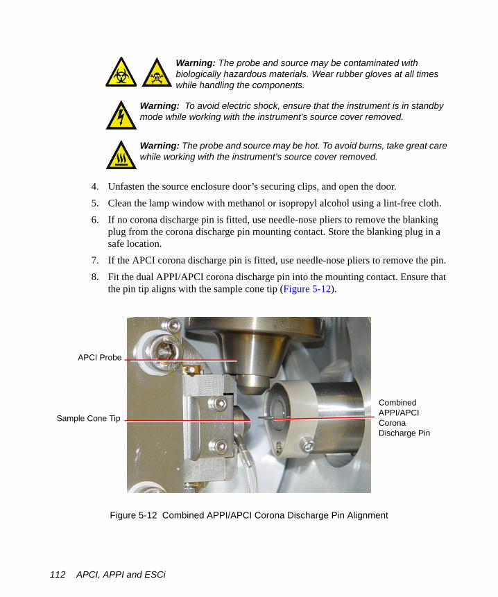
4. Unfasten the source enclosure door’s securing clips, and open the door.5. Clean the lamp window with methanol or isopropyl alcohol using a lint-free cloth.6. If no corona discharge pin is fitted, use needle-nose pliers to remove the blanking
plug from the corona discharge pin mounting contact. Store the blanking plug in a safe location.
7. If the APCI corona discharge pin is fitted, use needle-nose pliers to remove the pin.8. Fit the dual APPI/APCI corona discharge pin into the mounting contact. Ensure that
the pin tip aligns with the sample cone tip (Figure 5-12).
Figure 5-12 Combined APPI/APCI Corona Discharge Pin Alignment
Warning: The probe and source may be contaminated with biologically hazardous materials. Wear rubber gloves at all times while handling the components.
Warning: To avoid electric shock, ensure that the instrument is in standby mode while working with the instrument’s source cover removed.
Warning: The probe and source may be hot. To avoid burns, take great care while working with the instrument’s source cover removed.
APCI Probe
Sample Cone Tip
Combined APPI/APCI Corona Discharge Pin
112 APCI, APPI and ESCi

9. Close the source enclosure door, and fasten the securing clips.10. On the MassLynx Tune window, click Press for Operate and confirm the adjacent
instrument status indicator turns green.11. Click Switch Lamp On and confirm the Lamp readback is green.12. Click Switch Lamp Off and confirm the Lamp readback is red.
Obtaining Ion Beams for APCI and APPI
1. On the MassLynx Tune window, click Press for Standby to ensure that the instrument is in standby mode.
Note: If the LCT Premier has been in Standby for more than 2 hours it should be should be left in Operate for 1 hour to allow the instrument to stabilize.
2. Complete the connections between the HPLC pump, syringe pump, and APCI probe (Figure 5-2).
3. On the MassLynx Tune window, select Ion Mode > APcI+ or Ion Mode > APPI+.4. Select Settings > Multiple ion modes > Dual APPI/APcI to open the APPI+/APcI+
source tab (Figure 5-13).
Warning: To avoid possible high-pressure liquid jet spray, wear safety goggles when making the connections between the HPLC pump, LC column, syringe pump, and APCI probe.
Warning: To avoid electric shock, ensure that the instrument is in standby mode before making the connections between the HPLC pump, LC column, syringe pump, and APCI probe.
Operating in APPI and Dual APPI/APCI Modes 113
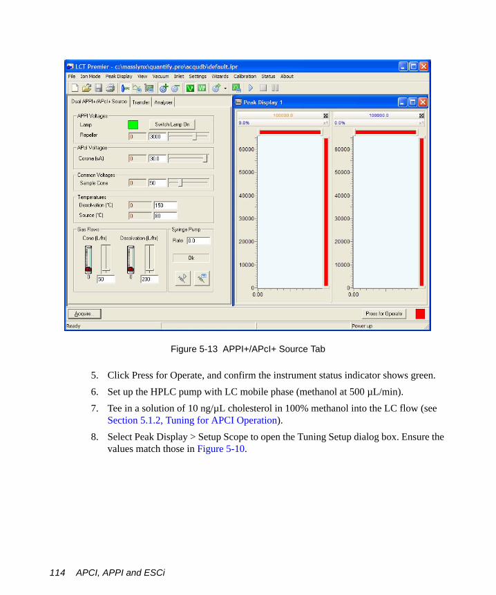
Figure 5-13 APPI+/APcI+ Source Tab
5. Click Press for Operate, and confirm the instrument status indicator shows green.6. Set up the HPLC pump with LC mobile phase (methanol at 500 µL/min).7. Tee in a solution of 10 ng/µL cholesterol in 100% methanol into the LC flow (see
Section 5.1.2, Tuning for APCI Operation).8. Select Peak Display > Setup Scope to open the Tuning Setup dialog box. Ensure the
values match those in Figure 5-10.
114 APCI, APPI and ESCi

Figure 5-14 Tuning Setup Dialog Box
9. Assuming that the probe is spraying, the peak display window will be showing some response.
Note: It may take a while for the sample to appear in the peak display window as any dead volume will need to be cleared first.
10. Select V or W mode, in this example W mode has been chosen.
11. Observe the cholesterol peaks at m/z 369.0 (M(-H2O)+H+) displayed in the peak display window.The APPI spectrum is displayed in the left pane and colored orange. The APCI spectrum is displayed in the right pane and colored blue (Figure 5-15).
12. Set the Source parameters to their optimum values as determined in Section 5.1, APCI Operation and “Obtaining an Ion Beam in APPI Mode” on page 107.
13. Tune for both modes by adjusting the Repeller Voltage for APPI and the Corona Voltage for APCI on the Tune window source page. Adjust the lamp position and APCI probe position if necessary, to give maximum peak intensity.
14. Observe the two peaks in the Tune window (Figure 5-15)
Note: W mode is selected.
Note: See Appendix D for details on customizing the display.
Caution: Do not to touch the probe with the repeller electrode:• A short circuit to the electrode would prevent proper ion detection.• The probe is hot and may damage the lamp assembly.
Operating in APPI and Dual APPI/APCI Modes 115

Figure 5-15 Dual Mode APCI/APPI
5.5 ESCi Multi-Mode Ionization
The LCT Premier, with the ESI probe installed and corona discharge pin fitted, can alternate between acquiring data in ESI and APCI modes. The software switches the voltage to the ESI capillary and the current to the APCI corona discharge pin continuously with interscan delays as short as 0.02 s.
5.5.1 Preparing for ESCi Operation1. If not already fitted, install the ESI probe (see Section 2.1).2. Fit the corona discharge pin (see Section 5.1.1).
APPI APCI
116 APCI, APPI and ESCi

Obtaining Ion Beams for ESCi
1. On the MassLynx Tune window, click Press for Standby to ensure that the instrument is in standby mode.
Note: If the LCT Premier has been in Standby for more than 2 hours it should be left in Operate for 1 hour to allow the instrument to stabilize.
2. Complete the connections between the HPLC pump, syringe pump, and ESI probe (see Figure 5-2).
3. On the MassLynx Tune window, select Ion Mode > ESI+.4. Select Settings > Multiple ion modes > ESCi to open the ESCi+/ESCi- source tab.5. Click Press for Operate, and confirm the instrument status indicator shows green.6. Set up the HPLC pump with LC mobile phase (70:30 acetonitrile:water at
300 µL/min).7. Tee in a solution of 10 ng/µL 17 α hydroxyprogesterone in 70:30 acetonitrile:water
into the LC flow (see Section 5.1).8. Select Peak Display > Setup Scope to open the Tuning Setup dialog box. Ensure the
values match those in Figure 5-10.
Figure 5-16 Tuning Setup Dialog Box
Warning: To avoid possible high-pressure liquid jet spray, wear safety goggles when making the connections between the HPLC pump, LC column, syringe pump, and APCI probe.
Warning: To avoid electric shock, ensure that the instrument is in standby mode before making the connections between the HPLC pump, LC column, syringe pump, and APCI probe.
ESCi Multi-Mode Ionization 117

9. Assuming that the probe is spraying the peak display window will be showing some response.
Note: It may take a while for the sample to appear in the peak display window as any dead volume will need to be cleared first.
10. Select V or W mode.
11. Observe the 17 α hydroxyprogesterone peak at m/z 331.2 (M+H+) displayed in the Tune window.The ESI spectrum is displayed in the left pane and colored red. The APCI spectrum is displayed in the right pane and colored blue (Figure 5-15).
12. Set the Source parameters to their optimum values as determined in Section 5.1 and Section 2.3.
13. Tune for both modes by adjusting the ES Voltages, Capillary Voltage for ESI, and the Corona Voltage for APCI on the Tune window Source page. Adjust the ESI probe position if necessary, to give maximum peak intensity.
14. Observe the two peaks in the Tune window (Figure 5-17).
Note: See Appendix D for details on customizing the display.
Caution: Do not to touch the probe with the repeller electrode:• A short circuit to the electrode would prevent proper ion detection.• The probe is hot and may damage the lamp assembly.
118 APCI, APPI and ESCi

Figure 5-17 Dual Mode ESCi
5.6 Creating an MS Method Files for Dual Mode Ionization
1. In the MassLynx window, click the MS Method icon to open the MS Method Editor.
2. Click to delete the current entry.
3. Click to open the MS Function Editor (Figure 5-18).
ESI APCI
Creating an MS Method Files for Dual Mode Ionization 119

Figure 5-18 MS Function Editor
4. For APCI/APPI dual mode select the required APPI ionization mode (APPI+ or APPI-) from the Ionization Mode drop-down list.For ESCi mode select the required electrospray ionization mode (ES+ or ES-) from the Ionization Mode drop-down list.
5. Enter the required parameters for the APPI or ES acquisition in the other frames.6. Click OK. The MS Function Editor closes, and the parameters are now included as
the APPI/ES entry in the MS Method Editor.7. Repeat steps 3 to 6, in this case selecting the required APCI ionization mode (API+
or API-) from the Ionization Mode drop-down list. This adds the APCI entry to the MS Method Editor (Figure 5-19).
Note: The parameter values entered in the Time (mins) frame must be identical for both functions.
120 APCI, APPI and ESCi

Figure 5-19 MS Method Editor with Dual APPI/APCI Functions
8. Click to save the MS Method file.
Note: Select the Tune file in the MS Tune File column in the Sample List to use tune parameters other than those in the currently open Tune file.
Creating an MS Method Files for Dual Mode Ionization 121

122 APCI, APPI and ESCi
Chapter 6 NanoLockSpray Interface
6.1 Overview of NanoLockSpray
The NanoLockSpray interface mounts directly onto the standard ZSpray source and provides a low flow capability NanoSpray probe (< 2 µL/min) orthogonal to the analyte NanoSpray probe for introduction of the reference compound.
This probe has the same capillary voltage applied as the standard probe and the nebulizing gas lines are coupled. Also on the NanoLockSpray interface is a baffle attached to a position indexed stepper motor, which admits the spray from either the standard analyte NanoSpray probe or the reference probe to the sampling cone for acquisition Shown graphically in Figure 6-1).
Spray indexing allows the analyte and reference data to be acquired into separate data files and the design of the baffle produces negligible cross talk between the two sprays. Data from the reference spray are used to calculate a correction factor for the mass scale calibration, which is then applied to the analyte data to provide exact mass information.
Overview of NanoLockSpray 123

Figure 6-1 Schematic Representation of NanoLockSpray
6.1.1 NanoLockSpray InstallationWhen you install the NanoLockSpray Interface proceed as follows (use Figure 6-2 as a guide):
124 NanoLockSpray Interface

Figure 6-2 NanoLockSpray Interface
1. Remove the probe and ion source enclosure as described in Section 8.5.4.2. Remove the baffle by undoing the thumbscrew. 3. Using the mounting screws supplied, attach the NanoLockSpray interface to the
ZSpray source. Ensure that the screws are fully tightened.4. Carefully refit the baffle. Slight adjustments to the baffle position can be made, if
necessary, by slightly loosening the mounting screws and repositioning. 5. Remove the cover of the reference probe by unscrewing the screw on the top. Insert
the probe and secure using two M3 screws. Replace Cover. 6. Connect the interlock cable to the double fissure connector cable and then to
Desolvation Heater socket on the instrument front panel. 7. Attach the adjuster assembly to the NanoLockSpray housing. Attach the nanoflow
sprayer to the adjuster assembly using the thumbscrew on the mounting plate. 8. Connect the high voltage cable from the standard NanoSpray probe into the socket
on the reference probe, and then connect the high voltage cable from the reference probe to the Capillary connector on the primary interface panel.
Note: If using the nanovial static (Borosilicate needle) sprayer the high voltage cable connected to the adjuster assembly will need to be changed to a type M956187CC1.
Overview of NanoLockSpray 125

9. Using the 1/16 inch Swagelock tee piece provided couple the PTFE gas lines from the two probes to the Nanoflow gas connector on the secondary interface panel.
10. Insert the endoscope. 11. Connect the motor cable. This goes from the underside of the motor to the Motor
socket on the secondary interface panel. 12. Insert blank plugs into the two Nebuliser gas connectors on the primary and
secondary interface panels.13. From the MassLynx Shortcut bar select Tools > Options from the MassLynx Short
Cut Bar to open the Options dialog box.14. Check the LockSpray check box.
6.1.2 Nano Reference Probe Assembly Instructions
1. Remove the outer cover from the probe (Figure 6-3).
Figure 6-3 Probe Without the Outer Cover
2. Make a sleeve for the 20-µm fused silica
Caution: Wear gloves whenever handling parts from the inside of the instrument. Check all of the parts are present. Refer to the shipping document for part numbers and descriptions.
Warning: To avoid injury from trace chemicals on the probe, always wear gloves.
126 NanoLockSpray Interface
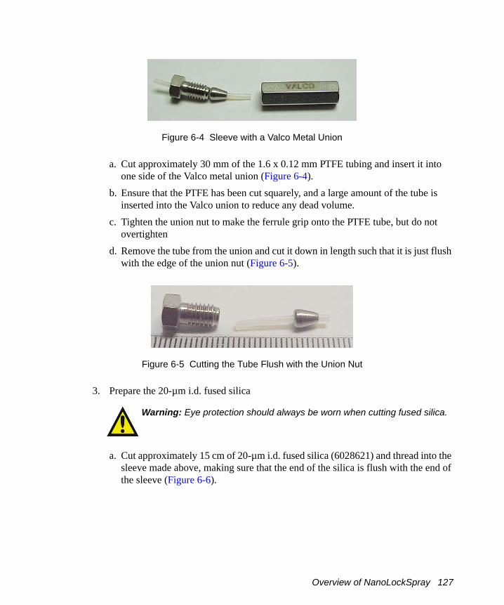
Figure 6-4 Sleeve with a Valco Metal Union
a. Cut approximately 30 mm of the 1.6 x 0.12 mm PTFE tubing and insert it into one side of the Valco metal union (Figure 6-4).
b. Ensure that the PTFE has been cut squarely, and a large amount of the tube is inserted into the Valco union to reduce any dead volume.
c. Tighten the union nut to make the ferrule grip onto the PTFE tube, but do not overtighten
d. Remove the tube from the union and cut it down in length such that it is just flush with the edge of the union nut (Figure 6-5).
Figure 6-5 Cutting the Tube Flush with the Union Nut
3. Prepare the 20-µm i.d. fused silica
a. Cut approximately 15 cm of 20-µm i.d. fused silica (6028621) and thread into the sleeve made above, making sure that the end of the silica is flush with the end of the sleeve (Figure 6-6).
Warning: Eye protection should always be worn when cutting fused silica.
Overview of NanoLockSpray 127

Figure 6-6 Cutting 20-µm Fused Silica to Size
b. Insert the sleeve and silica into the union. c. Push the silica through the union and progressively tighten the union nut and test
the tightness of its grip on the silica (Figure 10).
Figure 6-7 20-µm Fused Silica with Valco Union
d. Once the grip is sufficient to restrict movement, remove the nut and move the silica so it is flush with the edge of the PTFE sleeve.
e. Tighten up the nut to lock the fused silica in place. 4. Prepare the 75-µm i.d. Fused Silica.
a. Cut a long length (>30 cm) of 75 µm i.d. fused silica (6490512) and make a sleeve using a green PEEK tubing sleeve (6070190) (Figure 6-8).
Figure 6-8 70-µm Fused Silica Sleeve
b. Ensure that the silica has been cut squarely to reduce dead space. Thread the sleeve into a headless seal-tight nut and ferrule and thread the 75-µm i.d. fused silica through the sleeve making sure that the fused silica end is flush with the end of the sleeve.
128 NanoLockSpray Interface

Figure 6-9 70-µm Fused Silica Sleeve with Valco Union
c. Make sure that there is excess PEEK exposed to ensure minimum dead space and insert the silica and nut into the other side of the Valco union (Figure 6-9). Tighten using the nut extender tool.
5. Prepare Valco tee-piece:a. Use a 1.5-mm key to loosen the grub screw locking the Valco tee-piece onto the
probe assembly (Figure 6-10).
Figure 6-10 Valco Tee-Piece
b. Remove the Valco tee-piece. 6. Prepare a gas-tight fitting:
a. Take 30 mm of the 0.12 x 0.8 mm PTFE tubing and make a sleeve to form a gas tight seal at the tee piece, using the tee piece nut and ferrule.
Figure 6-11 Preparing a Gas-Tight Fitting
Overview of NanoLockSpray 129

b. Tighten the nut to make sure that the ferrule grips, taking care not to over-tighten. Remove the nut from the tee and cut down the PTFE tubing so that approximately 4 mm of sleeve protrudes from the nut of the tee (Figure 6-11).
7. Attach 20-µm id fused silica by threading the 2- µm i.d. fused silica attached to the union through this nut and sleeve, but do not tighten the tee nut as the silica needs to be mobile (Figure 6-12)
Figure 6-12 Attaching the 20-µm Fused Silica
8. Prepare a nebulizing capillary
Figure 6-13 Preparing the Nebulizing Capillary
a. Push the nebulizing capillary as far as it will go into the Valco tee piece and tighten the tee nut until the ferrule grips (Figure 6-13).
b. Thread the 20-µm i.d. fused silica through the tee piece and the nebulizing capillary.
c. Tighten the tee nut holding the silica sleeve so that it is finger tight and make sure that the fused silica is free to move though the tee (Figure 6-14).
130 NanoLockSpray Interface

Figure 6-14 Tee-piece with Threaded Silica
d. Thread the fused silica through the tee piece until the Valco union is close to the tee piece.
9. Thread the whole assembly through the probe assembly and seat the tee piece into its holder and tighten the grub screw to hold it into place (Figure 6-15).
Figure 6-15 Threading of Whole Assembly
10. Set the silica length: a. Position the union so that it is close to the tee and cut the fused silica near to the
nebulizing capillary. b. Reposition the union so that approximately 0.5 to 1 mm of fused silica protrudes
from the nebulizing capillary (Figure 6-16). c. Tighten the grub screw above the Valco union to secure it in place and also
tighten the gas seal nut on the tee to secure the fused silica.
Overview of NanoLockSpray 131

Figure 6-16 Setting the Silica Length
11. Prepare the nebulizing gas connection:a. Remove the PEEK bulkhead union (Figure 6-17).
Figure 6-17 Bulkhead Union
b. Attach the nebulizing gas tube (Figure 6-18).
Figure 6-18 Attaching the Nebulizing Gas Tube to the Bulkhead Union
c. Insert the nebulizing gas tube (6063060) through the small PEEK nut and ferrule and tighten until the ferrule grips.
12. Thread the tube through the assembly.a. Thread the tube through the plastic nut (Figure 6-19) and the rest of the assembly.
132 NanoLockSpray Interface

Figure 6-19 Threading the Tube Through the Probe Assembly
b. Tighten the nut so that the bulkhead union is held securely. c. Bend the tube so that it fits into the tee and tighten the nut so that the ferrule grips
the tube securely.d. Bend the tube back so that it runs neatly down the centre of the probe taking care
not to kink it (Figure 6-20).
Overview of NanoLockSpray 133

Figure 6-20 Bending the Tube
13. Prepare nebulizing PTFE tube: a. Cut a length of PTFE tube and insert it into the larger of the PEEK bulkhead
union nuts and tighten until the ferrule grips the tube securely. b. Using the 1/16 inch tee split the nanoflow gas supply into two feeds. Attach the
end of the reference probe PTFE tube to the tee and tighten until the ferrule grips (Figure 6-21).
134 NanoLockSpray Interface

Figure 6-21 Preparing the Nebulizing PTFE Tube
c. Attach the other end of the nanoflow gas supply to the analyte probe. d. Attach the probe casing to complete the assembly (Figure 6-22).
Warning: The Nanoflow assembly should not be operated without the probe casing attached.
Overview of NanoLockSpray 135

Figure 6-22 Casing Replaced
6.2 Operation and Tuning
The procedures for undertaking exact mass work using lock mass correction on the LCT premier are described in Chapter 2 and should be used with both the LockSpray and NanoLockSpray source.
The standard NanoSpray probe can be operated as on a standard NanoSpray source.
• The reference sprayer should be coupled to a pump capable of delivering the reference solution in a pulse-free manner over typically 0.3 to 2 µL/min (NanoLockSpray). A syringe or pressure "bomb" type pump is particularly suitable.
• The frequency with which the reference spray is sampled is user configurable but is generally set in the 2-to 10-second range.
• The acquisition time on the reference spray is the same as that set for the analyte spray.
• The minimum interscan delay usable with this interface is 0.1 s.
The operating conditions for the standard NanoSpray probe in NanoLockSpray are essentially the same as for the standard source and you should refer to the appropriate sections of Chapter 2 for optimization (see Chapter 2).
136 NanoLockSpray Interface
The positioning of the probe tip with respect to the sample cone and the optimum capillary voltage may differ somewhat from the standard arrangement due to the proximity of the baffle.
There are no positional adjustments possible for the reference probe.
• To obtain the required reference signal for exact mass work, adjust the concentration and flow rate of the reference material accordingly once the standard sprayer has been optimized for the analyte (150 cps).
• You can also optimize the Cone voltage for use with the reference compound can also be optimized as it is configurable in the experiment setup from the sample list.
• You can observe the signals from the analyte or reference sprayer can be observed for tuning purposes by using the LockSpray selection menu on the ES Source page in the Tune window.
6.3 Data Processing
During an acquisition, the analyte and reference data, from the NanoLockSpray source, are stored in the same folder as two separate functions and can be viewed independently.
When data processing with NanoLockSpray, you must set the number of reference scans to average (Figure 6-23). Data can also be acquired in both Centroid and Continuum mode.
1. Select the MS method from the MassLynx Instrument Shortcut Bar, to open the Experimental Setup dialog box (MS Method Editor).
2. Click the Experimental Setup dialog Toolbar button to open the Function Editor dialog box (Figure 6-23).
Caution: Care should be taken when setting these parameters to ensure that the probe does not electrically discharge to the baffle.
Data Processing 137

Figure 6-23 Reference Scan: Scans to Average
The Scans To Average parameter determines how many data points of the reference file, up to the time of the combined range of analyte data, will be averaged to provide a correction factor.
• Values between 5 and 10 are usually suitable. • If the value used is too low then ion statistics can affect the mass accuracy, too high
and there is the possibility that the instrument will have drifted slightly giving rise to an inappropriate correction factor.
6.4 Adding NanoFlow Options
You can fit the NanoLockSpray interface with several sprayer options, two of these are:
• Glass Capillary Option (Section 6.4.1)• Nano-LC Option (Section )
138 NanoLockSpray Interface

6.4.1 Glass Capillary Option
Installation
1. With the stage rotated outwards, unscrew the union from the end of the assembly.2. Carefully remove the capillary from its case by lifting vertically while pressing
down on the foam with two fingers.3. Over the blunt end of the capillary, pass the knurled nut, approximately 5 mm of
conductive elastomer, and finally the union.4. Tighten the nut (finger tight is sufficient) so that 5 mm of glass capillary is
protruding from the end of it. This distance is measured from the end of the nut to the shoulder of the glass capillary.
5. Load sample into the capillary using either a fused silica syringe needle or a GELoader tip.
6. Screw the holder back into the assembly - finger tight is sufficient.7. Ensure that Capillary is set to 0 V on the Tune window.8. Rotate the stage back into the interface using the stop and handle.
Note: When using a GELoader tip, break the nanovial in half, by scoring with a fused silica cutter. This enables the GELoader to reach the tip of the nanovial
Adjusting the Nanovial Tip PositionYou can adjust the position of the nanovial as shown (Figure 6-24). The tip is in line with the center of the sample cone, at a distance between two and three times the diameter of the cone orifice, as observed through the microscope.
Warning: Do not touch the sharp end of the capillary. As well as the risk of injury by a sliver of glass, the capillary may contain toxic samples.
Warning: The capillaries are extremely fragile and must be handled with great care. Always handle using the square end of the capillary. The needle may become inoperable if the sharp end is touched.
Adding NanoFlow Options 139
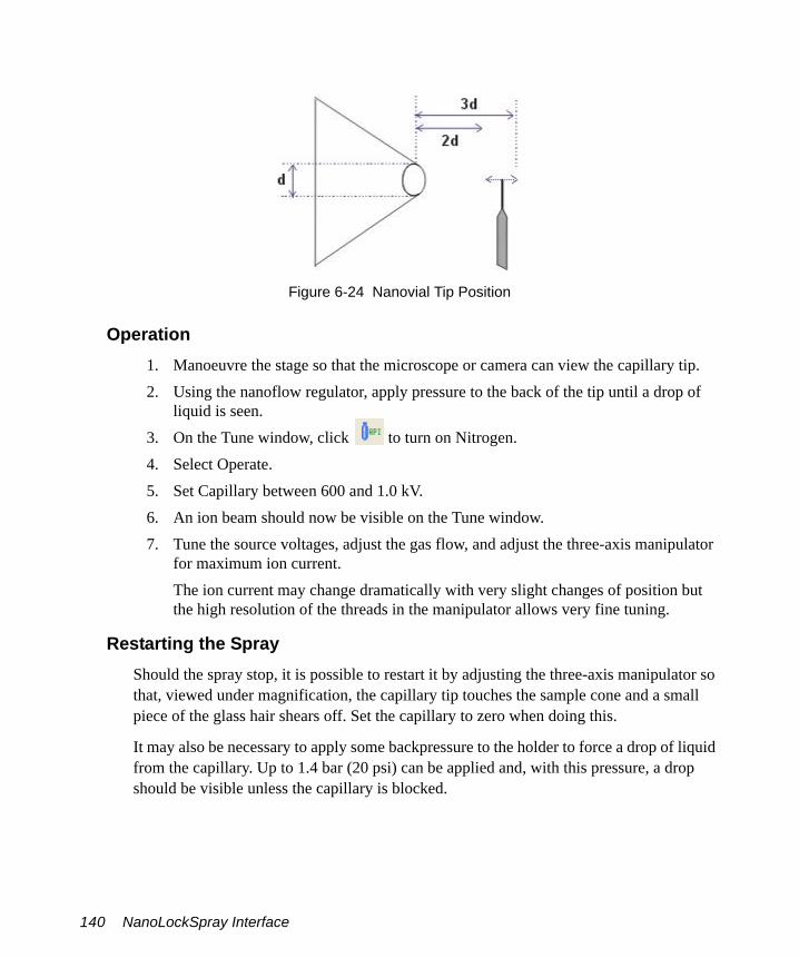
Figure 6-24 Nanovial Tip Position
Operation1. Manoeuvre the stage so that the microscope or camera can view the capillary tip.2. Using the nanoflow regulator, apply pressure to the back of the tip until a drop of
liquid is seen.3. On the Tune window, click to turn on Nitrogen.4. Select Operate.5. Set Capillary between 600 and 1.0 kV.6. An ion beam should now be visible on the Tune window.7. Tune the source voltages, adjust the gas flow, and adjust the three-axis manipulator
for maximum ion current.The ion current may change dramatically with very slight changes of position but the high resolution of the threads in the manipulator allows very fine tuning.
Restarting the SprayShould the spray stop, it is possible to restart it by adjusting the three-axis manipulator so that, viewed under magnification, the capillary tip touches the sample cone and a small piece of the glass hair shears off. Set the capillary to zero when doing this.
It may also be necessary to apply some backpressure to the holder to force a drop of liquid from the capillary. Up to 1.4 bar (20 psi) can be applied and, with this pressure, a drop should be visible unless the capillary is blocked.
140 NanoLockSpray Interface

6.5 Nano-LC Option
Installing the Nano-LC OptionWith the sprayer assembly removed from the stage and with reference to Figure 6-25:
1. Cut approximately 25 mm of the red stripe PEEK tubing and, using the plug cap and a Valco nut, set a ferrule to the correct position on the tubing.
Note: At this stage the ferrule is required only to grip the tubing lightly, and should not be too tight.
2. Cut the PEEK tubing such that 10 mm of the PEEK protrudes from the back of the ferrule.
3. Thread approximately 70-mm of the 90-µm o.d. fused silica through the new fitting.4. Ensure that the fused silica is flush with the PEEK sleeve.5. Again using the plug cap, tighten the nut further to ensure that the fused silica is
gripped. Some force may be required to do this.6. Remove the sleeved fused silica from the plug cap and remove the Valco nut.7. Place an O-ring onto the PEEK tube, using tweezers if necessary.
Note: The O-ring is required to seal the region between the ferrule and the end of the thread on the Nano-LC chamber.
8. Thread the sleeved fused silica through the Nano-LC chamber.9. Rotate the microvolume union in the body such that the ferrule seat is aligned
correctly.10. Insert the chamber into the Nano-LC body and tighten using a pair of spanners.
Note: The capillary can now be checked for flow by connecting the output from a Harvard syringe pump to the other side of the union and setting the flow to 1 µL/min, using a micropipette to measure the flow. It is recommended that a syringe with a volume of no more than 50 mL is used.
Warning: To avoid contamination from hazardous chemicals wear gloves when handling the sprayer assembly
Nano-LC Option 141

Figure 6-25 Nano-LC Assembly
142 NanoLockSpray Interface

11. Thread the fused silica through the nebulizing tip and screw in the nano-LC chamber such that it is screwed in approximately half way.
12. Cut the fused silica using a tile cutter and adjust the nebulizing tip further, such that 1 mm of fused silica protrudes from the tip.
13. Attach the nebulizing gas tubing to the sprayer using an O-ring and the special screw.
14. Attach the sprayer assembly to the stage.
Note: It may be necessary to alter the position of the thumbscrew underneath the baseplate to attach the sprayer correctly.
15. Swing the stage into the interface using the stop and handle.
6.5.1 Operating the Nano-LC OptionNote: For tuning purposes it may be useful to infuse a known sample in 95% water using a Harvard syringe pump.
1. Set the liquid flow to about 200 nL/min.2. Switch on the Gas on the MassLynx Tune window.3. Set the pressure of the gas on the regulator to approximately 0.5 bar (7 psi).4. Ensure there are no leaks of gas at the sprayer, particularly where the PTFE tubing is
connected to it.
Note: By viewing under magnification, the spray emanating from the capillary may be examined and tuned by altering the nebulizing tip such that a fine spray is observed. Altering the gas slightly may also help in this tuning process.
5. Swing the stage back out of the source and place the cover over the sprayer ensuring that the tubing coming from the sprayer is threaded correctly through it.
6. Lock the cover in place with two screws.7. Swing the stage back into the source and alter the translation stage (in / out
direction) such that the capillary is approximately 5 mm from the cone.8. Select Operate and set Capillary to approximately 2.5 kV.
An ion beam should now be present.9. Optimize the ion beam by altering the position of the spray using the controls of the
translation stage.
Nano-LC Option 143

10. Connect he sprayer to the HPLC system. The injection valve is plumbed as follows:• P from the pump.• C to the column (or to the union).• S is the sample port, attach a VISF sleeve here.• W is a waste port.
Note: A short tail of fused silica, attached to the entrance port of the union, and using low-pressure PTFE connectors will remove the need to move the stage. This will prevent accidental alteration of the sprayer’s position when changing between tuning and HPLC operation.
6.6 Changing Options
To change between the glass capillary and the Nano-LC options:
1. Rotate the stage outwards.
2. Remove the protective cover and release the captive screw located underneath the stage.
3. Lift off the holder and replace it with the alternative holder, securing it with the captive screw.
4. Replace the protective cover, ensuring that either the PTFE backpressure tubing (glass capillary option) or the fused silica transfer line is fed through the slot in the back of the protective cover along with the HV cabling.
Caution: To avoid permanent damage to the three-axis manipulator. use the stop and handle to rotate the stage.
144 NanoLockSpray Interface

Chapter 7 MUX-technology
The MUX-technology interface is a multiplexed electrospray interface, which allows multiple sample streams to be analyzed in parallel using a single mass spectrometer, significantly enhancing sample throughput capability. Figure 7-1 is a schematic diagram of the MUX-technology showing a single sample line only, for clarity. Figure 7-2 shows the MUX-technology interface.
7.1 The MUX-technology Interface
The interface mounts directly on the LCT Premier mass spectrometer’s standard ZSpray source (Figure 7-2). Four, five, eight or nine nebulization-assisted electrospray probe tips are arranged radially about the sample cone. The spray from each tip is successively admitted to the sample cone via a hole in the sampling rotor, which is driven by a programmable stepper motor. Heated dry nitrogen, supplied to the sampling rotor, provides desolvation of the currently-selected sample. An optical encoder on the sampling rotor shaft ensures that each detected mass spectrum is correctly assigned to the corresponding sample stream.
The MUX Exact InterfaceThe MUX Exact interface provides an additional reference spray inlet on a standard MUX giving 5 and 9-way sprayers. Infusion of a known reference compound into the reference sprayer allows for a lock-mass correction, to provide exact mass information. Since the reference spray is independent of the LC sprays, some of the common problems associated with post-column addition of a reference compound such as mass interferences, ion suppression and gradient effects are circumvented.
The MUX-technology Interface 145

Figure 7-1 MUX-technology Interface Schematic Diagram
Desolvation Gas
SampleNebulizer
Gas
Source EnclosureTurbomolecular
Pump2 Stage Source
Pumping
Sampling Rotor
ExhaustHeater Probe
Sample Cone
Isolation Valve
Stepper Motor
and SprayIndexing
E1M18 E2M28
Analyzer
146 MUX-technology

Figure 7-2 MUX-technology Interface
HV Connection
Nitrogen GasConnection
Source Enclosureis Replaced
Connection toMux Controller
Viewing Window
Desolvation GasHeater
Sampling Rotor
Outer Chamber
SampleInlet Connections
Probe SupportSegment
SampleCapillary
ElectroSprayProbe Tip
Optical EncoderDisk
Stepper MotorAssembly
The MUX-technology Interface 147

7.2 Installing the MUX-technology Interface
1. Remove the probe and ion source enclosure (see Section 8.5.4).2. Attach the MUX enclosure to the ZSpray source using the long mounting pillars
provided (Figure 7-3). Ensure that the pillars are full tightened, using a small bar inserted into the holes to act as a lever.
Figure 7-3 Attaching the MUX Enclosure
3. Place the housing end-flange on the mounting pillars and tighten down fully, using the nuts with retained O-rings (Figure 7-4).
MUX Enclosure
Mounting Pillars
148 MUX-technology

Figure 7-4 Attaching the Housing End Flange
4. Insert the MUX flange into the side of the MUX enclosure (Figure 7-5).a. Ensure the O-ring is correctly seated in the groove.b. Angle the base of the flange away from the housing and insert the upper part of
the probe support segment first.c. Move the flange upwards so that the probe support segment moves into the
window region on the housing.d. Slowly rotate the base of the flange towards the housing.
Note: It may be necessary to guide the lower capillaries into the housing by hand to prevent them being trapped by the flange.
e. Once the flange is mounted on the dowels, tighten down fully using the four screws.
Caution: To prevent damage to the stainless steel capillaries contained within the PTFE tubing, insert the MUX flange extremely carefully.
End Flange
Installing the MUX-technology Interface 149

Figure 7-5 Inserting the MUX Flange
5. Attach the nebulizer gas tube to the flange.6. Insert the desolvation gas heater into the aperture in the end flange and, while
looking through the housing window, guide the end of the heater into the hole in the outer chamber (Figure 7-6).
O-ring
Connection toMUX Controller
HV ConnectionNitrogen GasConnection
Sample Inlet Connections
150 MUX-technology

Figure 7-6 Inserting the Desolvation Gas Heater
7. Ensuring that the two sprung pins on the probe are contacting the metal earth plate on the end flange, tighten the probe into position.
8. Connect the following cables (Figure 7-7):a. Attach the high voltage cable from the HV connector to the Capillary connector
on the secondary interface panel (Section 1.6.2.2).b. Connect the desolvation gas heater cable to the Desolvation Heater socket on the
instrument front panel and the PTFE gas line to the Desolvation Gas connector.c. Connect the motor cable from the Motor socket on the Secondary Interface Panel
to the D-Type socket on the top of the motor cover.d. Connect the nebulizing gas line from the nebulizing gas connection on the MUX
flange to the nebuliser connector on the secondary interface panel.
Installing the MUX-technology Interface 151
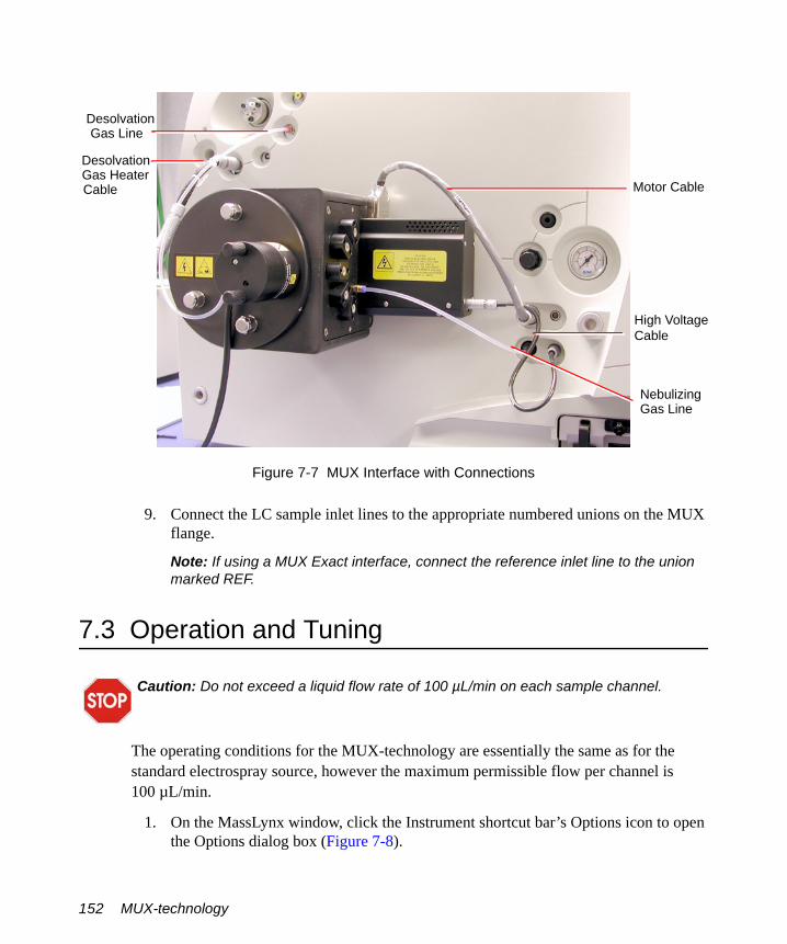
Figure 7-7 MUX Interface with Connections
9. Connect the LC sample inlet lines to the appropriate numbered unions on the MUX flange.
Note: If using a MUX Exact interface, connect the reference inlet line to the union marked REF.
7.3 Operation and Tuning
The operating conditions for the MUX-technology are essentially the same as for the standard electrospray source, however the maximum permissible flow per channel is 100 µL/min.
1. On the MassLynx window, click the Instrument shortcut bar’s Options icon to open the Options dialog box (Figure 7-8).
Caution: Do not exceed a liquid flow rate of 100 µL/min on each sample channel.
Motor Cable
High VoltageCable
NebulizingGas Line
DesolvationGas Line
DesolvationGas HeaterCable
152 MUX-technology

Figure 7-8 Options Dialog Box
2. Select Multi-probe Capability, Accurate Mass and Pos/Neg switching.3. Specify 4 or 8 probes depending on the type of MUX interface you have.4. If more than one HPLC pump is under direct MassLynx control, select Multi-Inlet
Capability.5. Set Number of Parallel Inlets to the number of HPLC pumps under direct MassLynx
control (typically 4).6. Click OK to close the Options dialog box.7. Click the Instrument shortcut bar’s MS Tune icon to open the Tune window
(Figure 7-9).
Operation and Tuning 153

Figure 7-9 Tune Window: ES+ Source Page
8. Select Ion Mode > ES+, if the ES+ Source page is not displayed.9. Set the parameters to the values shown in Table 7-1.
Table 7-1 Recommended ES+ Source Page Parameters
Parameter Recommended Value
VoltagesCapillary (V) 3000Cone (V) 50
TemperaturesSource Temp (°C) 120Desolvation Temp (°C) 400
154 MUX-technology

10. Set MUX to Position 1.11. Connect position 1 to the syringe
12. Click to turn on the nitrogen flow.13. On the Tune window’s ES+ Source tab, observe the Desolvation and Cone gas
flows; confirm that they have stabilized and are correct.14. Click Press for Operate, and confirm that the adjacent instrument status indicator
shows green.15. Load the sample syringe with sample.16. Select the correct syringe type:
a. Select Options > Syringe Type to open the Syringe Selection dialog box.b. Select the required syringe type from the drop-down list.
Note: If the syringe type is not listed, click Edit and add the relevant details.
c. Click OK.17. On the ES+ Source page, set Syringe, Pump Flow (µL/min) to 10.
18. Click to start the syringe pump.19. Observe the peak displayed on the Tune window. Tune the instrument for V and/or
W mode (see Section 2.3).20. Confirm that the displayed peaks have the correct resolution.
21. Click to stop the syringe pump..
Gas FlowDesolvation (L/hr) 700Cone (L/hr) 0
Warning: The liquids passing through the MUX-technology Interface may comprise biohazardous and/or toxic materials. Wear nitrile gloves at all times when working with this item.
Table 7-1 Recommended ES+ Source Page Parameters (Continued)
Parameter Recommended Value
Operation and Tuning 155

22. Set MUX to Position 2.23. Connect position 2 to the syringe pump.
24. Click to start the syringe pump.25. Observe the peak displayed on the Tune window, and check that the peak has similar
intensity to that obtained using Tune Spray Position 1.
Note: The sprayer-to-sprayer signal intensity may vary by up to ±30%, depending on the relative sprayer positions in the source.
If the signal intensity variation is too large, refer to Section 8.15.26. Repeat steps steps 21 to 25 for Tune Spray Positions 3, 4, 5, 6, 7, and 8.27. Select Reference and repeat steps steps 21 to 25 to tune the reference sprayer.
Warning: To avoid possible high-pressure liquid jet spray, wear safety goggles when changing the LC connection to the MUX-technology Interface.
Warning: To avoid electric shock, ensure that the instrument is in standby before changing the LC connection.
156 MUX-technology

Chapter 8 Preventative Maintenance
This chapter provides maintenance guidelines and procedures that are required maintain the instrument’s performance.
8.1 Maintenance Schedule
Table 8-1 lists periodic maintenance schedules that when followed ensure optimum instrument performance.
The maintenance frequencies shown apply to instruments that normally receive moderate use.
Table 8-1 Maintenance Schedule
Procedure Frequency
Gas-ballast the rotary pump (see Section 8.4).
Weekly (ESI). Daily (APCI).
Check and adjust the rotary pump oil level (see Section 8.4.3).
Weekly.
Change the rotary pump oil (see Section 8.4.4).
Every 3000 hours of pump operation.
Replace the rotary pump oil mist filter element (see Section 8.4.5).
Six monthly.Note: For applications that contaminate the rotary pump oil, this period will be reduced and must be determined from experience.
Replace the rotary pump odor filter element (see Section 8.4.5).
Monthly, or whenever the rotary pump emits an oily odor.
Clean the source assembly (see Section 8.5).
When sensitivity decreases to unacceptable levels.
Clean the ESI probe tip (see Section 8.6). When sensitivity decreases to unacceptable levels.
Maintenance Schedule 157

8.2 Safety and Handling
Bear in mind the following safety considerations when performing maintenance procedures.
Clean the APCI probe tip (see Section 8.8). When sensitivity decreases to unacceptable levels.
Clean the corona discharge pin (APCI mode) (see Section 8.7).
When sensitivity decreases to unacceptable levels.
Clean the ion block assembly (see Section 8.5).
When it is visibly fouled. When background or high peak contami-nants are unacceptably high.
Clean all source components (see Section 8.5).
When sensitivity decreases to unacceptable levels. When cleaning the cone gas cone, sample cone, and gas exhaust port fails to improve analytical results.
Replace the ESI probe capillary (see Section 8.10).
When sensitivity decreases to unacceptable levels.
Perform ZSpray APCI probe maintenance (see Section 8.11).Perform LockSpray Maintenance (see Section 8.14.1)Perform NanoLockSpray Maintenance (see Section 8.14.2)
Warning: To avoid possible electric shock, do not remove the instrument panels. There are no user-serviceable items inside.
Warning: To avoid possible electric shock, ensure that the instrument is in standby mode before commencing any maintenance.
Table 8-1 Maintenance Schedule (Continued)
Procedure Frequency
158 Preventative Maintenance

Cleanliness and care are very important whenever you remove internal assemblies from the instrument.
• Always prepare a clear clean area in which to work.• Make sure that any tools or spare parts that may be required are close at hand.• Obtain some small containers in which screws, washers, spacers etc. can be stored.• Use tweezers and pliers whenever possible.• If nylon or cotton gloves are used, take care not to leave fibers in sensitive areas.• Avoid touching sensitive parts with fingers.• Before reassembling and replacing dismantled components, inspect O-rings and
other vacuum seals for damage. Replace with new ones if in doubt.
Should a fault occur soon after a particular part of the system has been repaired or otherwise disturbed, it is advisable first to ensure that this part has been correctly refitted and / or adjusted, and that adjacent components have not been inadvertently disturbed.
8.3 Cooling Fans and Air Filters
Always ensure that none of the cooling fans are obstructed. It is essential that the fan filter is checked and cleaned regularly, and replaced if there is any doubt about its effectiveness.
8.3.1 Changing the Air Filter1. Using a screwdriver remove the single screw holding the filter assembly to the
right-side of the instrument (Figure 8-1).
Warning: To prevent injury, always observe good laboratory practices when handling solvents, changing tubing, or operating the LCT Premier. Know the physical and chemical properties of the solvents used. See the Material Safety Data Sheets for the solvents in use.
Warning: To avoid burns, take great care while working with the probe and source as they are liable to be hot.
Warning: The instrument components are liable to be contaminated with biologically hazardous and toxic materials. Wear rubber gloves at all times while handling the components.
Cooling Fans and Air Filters 159

Figure 8-1 Filter Assembly on Instrument
2. Remove the whole assembly from the side of the instrument.3. Remove the six screws holding the support mesh in place (Figure 8-2).
Figure 8-2 Filter Assembly Removed
4. Lift off the support mesh and replace the filter.5. Refit the support mesh and secure the whole assembly to the side of the instrument.
Screw
Screws
SupportMesh
160 Preventative Maintenance

8.4 The Vacuum System
8.4.1 Gas-Ballasting and Rotary Pump Oil Recirculation
Gas-ballasting serves two important purposes:
• When rotary pumps are used to pump solvent vapors, the solvent vapor can become dissolved in the pump oil causing an increase in backing line pressure. Gas-ballasting purges the oil to remove dissolved contaminants.
• Oil mist expelled from the rotary pump exhaust is trapped in the oil mist filter. This oil is returned to the rotary pump during gas ballasting.
Figure 8-3 Rotary Pump Maintenance
Warning: To avoid potential burns when handling rotary pumps, be aware both rotary pumps will run hot after several hours of operation.
Caution: Do not vent the instrument with the E2M28 manual gas valve open. The E1M18 manual gas-ballast valve should remain open at all times.
Warning: Both rotary pumps will run hot after several hours of operation. Personnel should be aware of the potential for burns when using them.
Gas Ballast
Drain Plug
Exhaust
Filler Plug
Oil Level Indicator
Oil Mist FilterOil Mist Filter
Filter Plug
Oil Level Indicator
Drain Plug
ExhaustGas Ballast
The Vacuum System 161

Gas ballasting serves two important purposes:
• When rotary pumps are used to pump away solvent vapors, the solvent vapor can become dissolved in the pump oil causing an increase in backing line pressure. Gas ballasting is a method of purging the oil to remove dissolved contaminants.
• Oil mist expelled from the rotary pump exhaust is trapped in the oil mist filter. This oil is returned to the rotary pump during gas ballasting.
The LCT Premier has two rotary pumps:
• An E1M18 pumping the source block.• An E2M28 providing backing for the turbo pump and also pumping the first ion
guide.
Because the source block is maintained at a relatively high pressure, the rate of oil mist being expelled from the E1M18 pump is considerably higher than that from the E2M28 pump. Consequently, it is recommended that the E1M18 pump is operated continuously in gas-ballast mode so that the pump oil is continuously recirculated.
Gas-Ballasting the E2M28Note: It is normal for the rotary pump to make more noise when the gas ballast valve is open.
When the rotary pump draws large quantities of solvent vapors, the vapors tend to condense in the pump oil, reducing pump efficiency. Gas-ballasting purges condensed contaminants from the oil, and returns any oil to the pump from the oil mist filter. Gas-ballast the rotary pump when any of the following conditions apply:
• With ESI or APCI operation, once a week.• The pump oil appears cloudy.• The vacuum pressure is higher than normal.• condensate forms in the rotary pump exhaust line.• When changing the rotary pump oil.• The level of accumulated oil in the oil mist filter is high.
Caution: The instrument should not be vented with the E2M28 manual gas valve open. The E1M18 manual gas ballast valve should remain open at all times.
162 Preventative Maintenance

To gas-ballast the pump:
1. Turn on the gas-ballast control (Figure 8-4).
Figure 8-4 E2M28 Rotary Pump
Caution: Failure to routinely gas-ballast the rotary pump shortens oil life, and consequently pump life.
Caution: Do not vent the instrument while the rotary pump is gas-ballasting.
Caution: Do not gas-ballast the E2M28 rotary pump while the LCT Premier is in Operate mode.
Caution: Never gas-ballast the rotary pump for more than 2 hours.
Warning: To avoid burns, take great care while working with the rotary pump as it will be hot.
Power SwitchInlet Port
Gas-Ballast control
Outlet Nozzle
Oil Filter Plug
Max
Oil Sight Glass
MIN
Oil Drain Plug
The Vacuum System 163

2. When the oil is clear and has drained back to the rotary pump, return the gas-ballast control to its normal position.
8.4.2 Replacing the Activated Alumina in the Foreline Trap The foreline trap stops oil vapor migrating from the rotary pump to the mass spectrometer. During normal use, the activated alumina (sorbent) absorbs any oil vapor, becoming brown in color. The sorbent should be replaced when this discoloration reaches the region of the trap furthest from the pump (the vacuum side). The manufacturers recommend that the sorbent is replaced every 3 months.
With the instrument vented and the pump switched off, replace the sorbent as described in the manufacturer’s literature.
8.4.3 Checking the Rotary Pump Oil
The oil level can be checked while the pump is operating. However, the instrument must be vented and shut down before adding oil.
The rotary pump oil level appears in the oil level sight glass on the pump (see Figure 8-4).
Check the oil level weekly; at all times it should be at, or near, the MAX level as indicated by the markings beside the sight glass. If oil must be added, vent and shut down the LCT Premier before removing the oil filler plug (see Section A.2.3, Complete Instrument Shutdown).
Examine the oil each time the oil level is checked. It should be colorless and free of visible contaminants. If the oil is discolored, change it as described in Section 8.4.4.
8.4.4 Changing the Rotary Pump OilChange the rotary pump oil every 3 to 4 months, or whenever it becomes noticeably discolored.
Required Materials• Rubber gloves• Flat-blade screwdriver• Container to catch used oil
Warning: To avoid burns, take great care while working with the rotary pump as it will be hot.
164 Preventative Maintenance

• Funnel• Vacuum oil [use only Ultragrade 19 or Inland Q45 (Edwards 45) vacuum pump oil]
Procedure
1. Operate the pump to warm the oil before draining.2. Gas-ballast the rotary pump (see Section 8.4.1, Gas-Ballasting and Rotary Pump Oil
Recirculation).3. Vent the instrument and set the pump power switch to the off position.
4. Raise the pump 6 to 8 inches (150 to 200 mm) above the floor, if necessary.5. Place an object under the motor to tilt the pump toward the side on which the oil
drain plug is located (see Figure 8-4).6. Remove the oil filler plug to facilitate drainage.7. Using the flat-blade screwdriver, remove the oil drain plug.8. Let the oil drain completely.9. Refit the oil drain plug.10. Fill the pump until the oil in the sight glass reaches the MAX level.11. Allow a few minutes for the oil to drain into the pump.12. Recheck the oil level and, if necessary, add more oil.13. Refit the oil filler plug and, if necessary, lower the pump to the floor.14. Set the pump power switch to the on position.
Warning: The rotary pump oil is liable to be contaminated with toxic and biohazardous materials. Wear rubber gloves at all times while handling the oil and ensure that the waste oil is correctly disposed of according to local environmental regulations.
Warning: To avoid burns, take great care while working with the rotary pump and rotary pump oil, as they will be hot.
The Vacuum System 165

8.4.5 Changing the Oil Mist and Odor Filter Elements
Required Materials• Rubber gloves• 4-mm Allen key (hex wrench)• Lint-free cloth
Procedure
1. Gas-ballast the rotary pump to drain the oil from the oil mist filter (see Section 8.4.1, Gas-Ballasting and Rotary Pump Oil Recirculation).
2. Vent the instrument and set the pump power switch to the off position.3. Wipe clean the outside of the oil mist filter body.4. Use the Allen key to remove the four screws that secure the filter’s upper body to
the lower body.
5. Remove the upper body from the lower body.
Warning: The rotary pump oil is liable to be contaminated with toxic and biohazardous materials.Wear rubber gloves at all times while handling the oil mist filter assembly
Warning: To avoid burns, take great care while working with the rotary pump and oil mist filter assembly, as they will be hot.
166 Preventative Maintenance

This exposes the oil filter element and odor filter element.
6. Lift out the element(s) that are to be replaced.
Oil Filter Element
Odor Filter Element
The Vacuum System 167

7. Wipe clean the insides of the upper and lower body assemblies.8. Ensure that the oil filter element O-ring is in position on the lower body assembly.
9. Fit the new filter elements to the lower body assembly, ensuring that the foam sealing rings are correctly seated on the top and bottom of the elements.
10. Refit the upper body assembly to the lower body assembly.11. Fit and tighten the four screws that secure the upper body to the lower body.
O-Ring
168 Preventative Maintenance

8.5 Cleaning the Source Components
8.5.1 OverviewClean the source components (sample cone and cone gas cone) when:
• They are visibly fouled.
• LC and sample-related causes for decreased signal intensity have been ruled out.
If cleaning these parts fails to increase signal sensitivity, also clean the extraction cone, source ion guide, and ion block.
To clean the source components:
1. Disassemble the source components and source ion guide assembly (see Sections 8.5.2 to 8.5.6).
2. Clean the source components and source ion guide assembly (see Sections 8.5.7 to 8.5.10).
3. Reassemble the source ion guide assembly and the source components (see Sections 8.5.11 to 8.5.14).
Required Materials• Rubber gloves• Needle-nose pliers• Set of Allen keys (hex wrench) including 2.5-mm and 6-mm• Jeweller’s screwdriver• Large, flat-blade screwdriver• Glass-fiber pen• Appropriately sized glass vessels, in which to completely immerse components
when cleaning. Use only glassware not previously cleaned with surfactants.• HPLC-grade methanol• HPLC-grade water• Formic acid• Ultrasonic bath• Source of oil-free, inert gas (nitrogen or helium) for drying (air-drying optional).
Cleaning the Source Components 169

• Lint-free paper towels
8.5.2 Removing the Probe from the Source1. Disconnect the LC system from the probe.2. On the MassLynx window, click Press for Standby and ensure that the adjacent
instrument status indicator turns red.3. Wait for 3 minutes to allow the desolvation gas flow to cool the probe and source.
4. Click to turn off the nitrogen gas flow.
5. Disconnect the electrical connection(s) on the instrument front panel.6. Disconnect the PTFE tubing at the Nebulizer gas connection on the front panel.7. Undo the two thumbscrews securing the probe to the probe adjuster.
8. Carefully remove the probe from the probe adjuster.
8.5.3 Removing the Sample Cone
Warning: To avoid burns, take great care while working with the instrument’s source cover removed. The probe and source are liable to be hot.
Warning: To avoid contamination from previously sprayed sample, wear gloves at all times when handling the probe. This also prevents finger-grease contaminating the capillary.
Caution: To avoid damaging the probe seals when removing an APCI probe, ensure that the probe temperature is less than 150 °C [as displayed on the Tune windows’s APcI Probe Temp (°C) readback] before removing the probe.
Warning: The source components are liable to be contaminated with toxic and biohazardous materials. Wear rubber gloves at all times while handling the components.
170 Preventative Maintenance

1. Unfasten the source enclosure door’s securing clips and open the door.2. If using LockSpray unplug and remove the baffle and motor assembly.
If using an APCI probe, carefully remove the corona discharge pin.
Warning: To avoid possible electric shock, ensure that the instrument is in standby mode before commencing this procedure.
Warning: The source is liable to be hot. To avoid burns, take great care while working with this item.
Caution: Failure to close the isolation valve before removing the sample cone is liable to damage the instrument.
Baffle
PTFE Tube
Cleaning the Source Components 171

3. Close the isolation valve by moving its lever fully to the right.
4. Pull out the PTFE tube attached to the cone gas nozzle.
Note: Use a flat-blade screwdriver to push the collar back while removing the tube.
5. Use an Allen key to remove the two cone retaining plate screws.6. Remove the cone retaining plate.7. Carefully remove the sample cone/cone gas cone assembly from the isolation valve
body.8. Use a jeweller’s screwdriver to carefully remove the O-ring from the sample
cone/cone gas cone assembly.
Isolation Valve
Sample Cone / Cone Gas Cone Assembly
172 Preventative Maintenance

9. Separate the sample cone and cone gas cone.Figure 8-5 shows the sample cone, cone gas cone, and O-ring.
Figure 8-5 Sample Cone/Cone Gas Cone Assembly Components
10. Clean the sample cone and cone gas cone as described in Section 8.5.7, Cleaning the Sample Cone and Cone Gas Cone.
8.5.4 Removing the Ion Source Enclosure and Ion Block
1. Vent the instrument as described in Section A.2, Shutting Down the LCT Premier.
2. Disconnect the Desolvation Heater electrical connection on the instrument front panel.
Caution: The sample cone is very fragile. To avoid damage, never place the sample cone on its tip; always place it on its flanged base.
Warning: To avoid possible electric shock, ensure that the instrument is shut down and is isolated from the mains power supply.
Warning: The source is hot, so allow it to cool down for at least 30 minutes before proceeding.
O-Ring
Cone Gas Sample Cone
Cleaning the Source Components 173
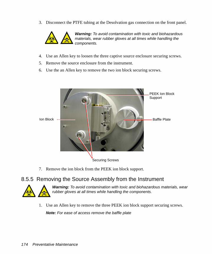
3. Disconnect the PTFE tubing at the Desolvation gas connection on the front panel.
4. Use an Allen key to loosen the three captive source enclosure securing screws.5. Remove the source enclosure from the instrument.6. Use the an Allen key to remove the two ion block securing screws.
7. Remove the ion block from the PEEK ion block support.
8.5.5 Removing the Source Assembly from the Instrument
1. Use an Allen key to remove the three PEEK ion block support securing screws.
Note: For ease of access remove the baffle plate
Warning: To avoid contamination with toxic and biohazardous materials, wear rubber gloves at all times while handling the components.
Warning: To avoid contamination with toxic and biohazardous materials, wear rubber gloves at all times while handling the components.
Securing Screws
Ion Block
PEEK Ion BlockSupport
Baffle Plate
174 Preventative Maintenance

2. Remove the PEEK ion block support from the pumping block.
Note: Ensure that the three O-rings remain in position on the rear face of the support.
3. Carefully remove the source assembly (see Figure 8-6) from the pumping block.
Caution: Take care not to scratch the internal bore of the pumping block, as the ion tunnel assembly is withdrawn.
PEEK Ion Block Support
Securing Screws
Pumping Block
SourceAssembly
Cleaning the Source Components 175

Figure 8-6 Source Ion Guide Assembly
4. With a flat bladed screwdriver remove the three screws securing the differential aperture plate to the ion guide.
5. Carefully remove the plate from the ion guide. The ion guide assembly components are shown in Figure 8-7.
Differential Aperture Plate
176 Preventative Maintenance

Figure 8-7 Source Ion Guide Assembly Components
6. Clean the source ion guide and differential aperture plate (see Section 8.5.8).
8.5.6 Disassembling the Source Ion Block
1. Remove the two lock nuts from the bottom of the isolation valve body.
Warning: To avoid contamination with toxic and biohazardous materials, wear rubber gloves at all times while handling the components.
O-ring
Differential AperturePlate
Cleaning the Source Components 177

2. Remove the washer and retaining ring from the isolation valve stem.
3. Remove the isolation valve stem from the isolation valve body (gently push the stem while repeatedly opening and closing the isolation valve).The isolation valve stem components are shown in Figure 8-8.
Lock Nuts
Isolation Valve Assembly
Washer Retaining Ring
Isolation Valve Stem
178 Preventative Maintenance

Figure 8-8 Isolation Valve Stem Components
4. Clean the isolation valve stem as described in (see Section 8.5.10).5. Use an Allen key to remove the four ion block cover plate securing screws.
6. Remove the ion block cover plate.
Ion Block Cover Plate
Cleaning the Source Components 179

7. Use an Allen key to remove the two screws securing the heater cartridge wires to the PEEK terminal block.
8. Use the needle-nose pliers to carefully swing the ring terminal tags out of the terminal block.
Cartridge Heater Wire Securing Screws
PEEK Terminal Block
Ring Terminal Tag
180 Preventative Maintenance

9. Use the needle-nose pliers to gently slide the heater cartridge assembly out of the ion block.
10. Use a jeweller’s screwdriver to carefully remove the D-shaped seal from the ion block.
Heater Cartridge Assembly
D-Shaped Seal
Cleaning the Source Components 181

11. Use an Allen key to remove the PEEK terminal block securing screw.
12. Use the needle-nose pliers to remove the PEEK terminal block from the ion block.
13. Use a wrench to remove the choke.14. Clean the ion block as described in (see Section 8.5.9).15. Reassemble the ion block as described in (see Section 8.5.11).
8.5.7 Cleaning the Sample Cone and Cone Gas Cone
Warning: To avoid contamination with toxic and biohazardous materials, wear rubber gloves at all times while handling the components.
PEEK Terminal Block Securing Screw
182 Preventative Maintenance

1. Use a glass-fiber pen to remove gross contamination from the cone gas cone surface by gentle abrasion.
2. If the sample cone contains debris, place a drop of formic acid on its orifice.3. Immerse the sample cone and cone gas cone in separate glass vessels containing
methanol:water (1:1).
Note: If the parts are obviously contaminated, use a mixture of 45% methanol, 45% water, and 10% formic acid.
4. Place the vessels in the ultrasonic bath for 30 minutes.5. If formic acid was used in the cleaning solution:
a. Rinse the parts by immersing them in separate glass vessels containing water and placing the vessels in the ultrasonic bath for 20 minutes, to remove the formic acid.
b. Displace the water by immersing the parts in separate glass vessels containing methanol and placing the vessels in the ultrasonic bath for 10 minutes.
6. Carefully remove the parts from the vessels and blow-dry them using inert, oil-free gas.Alternatively, the parts may be placed on lint-free towels and allowed to air dry. Wipe off any water spots with a lint-free cloth.
Caution: The sample cone is very fragile; to avoid damage, never place the sample cone on its tip, always place it on its flanged base.
Warning: Use extreme care when working with formic acid. Use a fume hood and appropriate protective equipment.
Warning: Handle the container carefully. The exothermic reaction caused by the addition of formic acid to water may have caused the container to heat up.
Cleaning the Source Components 183

8.5.8 Cleaning the Source Components
Differential Aperture Plate:Use a glass-fiber pen to gently remove ion burn marks; pay particular attention to the inner surfaces of the differential aperture plate.
Source Assembly:1. Flush-out the assembly, using methanol from a wash-bottle.2. Immerse the assembly in a glass vessel containing methanol:water (1:1).3. Place the vessel in the ultrasonic bath for 30 minutes.
4. Carefully remove the assembly from the vessel and blow-dry it using inert, oil-free gas.
5. Visually inspect the assembly to ensure that no fibers from the wire brush are lodged in the assembly. If fibers are present, repeat the procedure from step 1 onwards.
Warning: To avoid contamination with toxic and biohazardous materials, wear rubber gloves at all times while handling the components.
Caution: Use only methanol or water as solvents when cleaning the source assembly. Use of acetone, chlorinated solvents, or acid will damage the assembly.
Caution: Take great care not to damage the assembly’s plates when using the wire brush for cleaning.
Caution: Do not dry the source assembly by any method other than blow-drying, otherwise reintroduced contamination may lead to difficulty in pumping down the instrument.
184 Preventative Maintenance

8.5.9 Cleaning the Ion Block
1. Immerse the ion block in a glass vessels containing methanol:water (1:1).
Note: If the components are obviously contaminated, use a mixture of 45% methanol, 45% water, and 10% formic acid.
2. Place the vessels in the ultrasonic bath for 30 minutes.3. If formic acid was used in the cleaning solution:
a. Rinse the ion block by immersing them in separate glass vessels containing water and placing the vessels in the ultrasonic bath for 20 minutes to remove the formic acid.
b. Displace the water by immersing the ion block in separate glass vessels containing methanol and placing the vessels in the ultrasonic bath for 10 minutes.
4. Carefully remove the ion block from the vessel and blow-dry them using inert, oil-free gas.Alternatively, place the components on lint-free towels and allow to air dry. Wipe off any water spots with a lint-free cloth.
8.5.10 Cleaning the Isolation Valve Stem
1. Use a glass-fiber pen to remove carbon deposits by gentle abrasion.2. Rinse the valve stem by placing it in a vessel containing methanol:water (1:1) and
placing the vessel in an ultrasonic bath for 20 minutes.
Warning: To avoid contamination with toxic and biohazardous materials, wear rubber gloves at all times while handling the components.
Warning: Use extreme care when working with formic acid. Use a fume hood and appropriate protective equipment.
Warning: To avoid contamination with toxic and biohazardous materials, wear rubber gloves at all times while handling the components.
Cleaning the Source Components 185

8.5.11 Reassembling the Source Ion BlockNote: Wear clean rubber gloves when reassembling the source components.
1. Check the condition of all O-rings and seals; if damaged, replace with new items.2. Fit the ion block blanking plug to the ion block and tighten.3. Fit the PEEK terminal block to the ion block.4. Fit and tighten the PEEK terminal block securing screw.5. Fit the D-shaped seal to the ion block, ensuring that it is correctly seated.6. Use the needle-nose pliers to slide the new heater cartridges into the ion block.7. Position the two heater cartridge ring tags onto the PEEK block terminals.8. Use an Allen key to fit and tighten the two screws securing the heater cartridge
wires to the PEEK terminal block.9. Refit the ion block cover plate.10. Fit and tighten the four ion block cover plate securing screws.11. Fit the isolation valve stem to the isolation valve body.12. Fit the washer and retaining ring to the bottom of the isolation valve stem.13. Fit and tighten the two lock nuts on the bottom of the isolation valve stem.
8.5.12 Reassembling and Fitting the Source Ion Guide Assembly to the Instrument1. Refit the differential aperture plate and O-ring to the ion guide.2. Feed the ion guide assembly into the instrument, ensuring the location dowel locates
correctly within the analyzer assembly. Ensure that the assembly is pushed fully in.3. Fit the PEEK ion block support to the pumping block.4. Fit and tighten the three PEEK ion block support securing screws.
8.5.13 Fitting the Ion Block and Ion Source Enclosure1. Check the condition of all O-rings; if damaged, replace with new items.2. Ensure that all the O-rings are in position on the ion block.3. Fit the ion block to the PEEK ion block support.4. Fit and tighten the two ion block securing screws.5. Fit the source enclosure to the pumping block.
186 Preventative Maintenance

6. Fit and tighten the three source enclosure securing bolts.7. Connect the Desolvation Heater electrical connection on the instrument front panel.8. Connect the PTFE tubing at the Desolvation gas connection on the front panel.
8.5.14 Fitting the Sample Cone
1. Fit the sample cone into the cone gas cone.2. Check the condition of the sample cone/cone gas cone assembly O-ring; if damaged,
replace with a new item.3. Fit the O-ring to the sample cone/cone gas cone assembly.4. Fit the sample cone/cone gas cone assembly to the side of the isolation valve body.5. Fit the cone retaining plate.6. Fit and tighten the two cone retaining plate securing screws.7. Connect the PTFE tube to the cone gas cone.8. Open the isolation valve by moving its lever fully to the left.9. If an APCI probe is to be used, fit the corona discharge pin.
10. Close the source enclosure door and fasten the clips.
8.5.15 MCP Conditioning
After the instrument has been vented the MCPs should be reconditioned.
1. Select V mode.2. Click the Analyser tab in the Tune window and set MCP voltage to 0. 3. Switch to Operate.4. Select Settings > MCP Conditioning.
5. Click to start the MCP conditioning process. It will take 2 hours.
Caution: The sample cone is very fragile. To avoid damage, never place the sample cone on its tip; always place it on its flanged base.
Caution: Do not start the MCP conditioning until the TOF vacuum pressure has been stable at < 3e-6 mBar for at least 1 hour.
Cleaning the Source Components 187

8.6 Cleaning or Replacing the ESI Probe Tip
Clean the ESI probe tip if a blockage occurs in the internal metal sheathing through which the stainless steel capillary passes.
Replace the ESI probe tip if the threads are damaged.
Replace the O-ring if gas leaks from the O-ring.
Required Materials• Rubber gloves.
• ¼-inch (6-mm) Allen key (hex wrench).• Appropriately-sized glass vessels, in which to completely immerse components
when cleaning.Use only glassware not previously cleaned with surfactants.
• HPLC-grade methanol.• HPLC-grade water.• Ultrasonic bath.• Source of oil-free, inert gas (nitrogen or helium) for drying (air-drying optional).
Procedure
1. Remove the probe from the source as shown in Section 8.5.2, Removing the Probe from the Source.
2. Use the ¼-inch (6-mm) wrench to unscrew and remove the probe tip.3. If the probe tip is damaged replace with a new tip; alternatively clean the probe tip
as follows:a. Immerse the probe tip in a glass vessel containing methanol:water (1:1).b. Place the vessel in the ultrasonic bath for 20 minutes.
Warning: To avoid contamination from previously sprayed sample, wear gloves at all times when handling the probe. This also prevents finger-grease contaminating the capillary.
Caution: Perform all work on the probe on a clean work bench.
188 Preventative Maintenance
c. Carefully remove the probe tip from the vessel and blow-dry using inert, oil-free gas.
4. If necessary, remove the O-ring and fit a new O-ring.5. Fit and tighten the probe tip to the probe.6. Adjust the probe tip so that the fully extended capillary (when the probe nebulizer
adjuster knob is fully screwed down) protrudes by approximately 1 to 1.5 mm.7. Refit the probe to the source.
8.7 Cleaning or Replacing the Corona Discharge Pin
Clean the corona discharge pin if it appears to be corroded or black, or when the signal intensity weakens.
Required Materials• Rubber gloves• Needle-nose pliers• Lapping film• HPLC-grade methanol• Lint-free tissue
Procedure
1. Remove the probe from the source, (see Section 8.5.2).2. Unfasten the source enclosure door’s securing clips and open the door.
Warning: To avoid contamination with toxic and biohazardous materials, wear rubber gloves at all times while handling the components.
Warning: To avoid possible electric shock, ensure that the instrument is in standby mode before commencing this procedure.
Warning: The probe and source are liable to be hot. To avoid burns, take great care while working with these items.
Cleaning or Replacing the Corona Discharge Pin 189

3. Use the needle-nose pliers to remove the corona discharge pin from the source, pulling it straight out.
4. Clean and sharpen the tip of the pin with the lapping film, then wipe it clean with a methanol-saturated tissue. Replace the pin by a new pin if it is deformed or otherwise damaged.
5. Reinstall the pin with the tip pointing toward the sample cone apex.
6. Close the source enclosure door and fasten the clips.7. Refit the probe.8. Reconnect the front panel gas and electrical connections.
8.8 Cleaning the APCI Probe Tip
Clean the APCI probe tip when a buffer build-up is detected on the probe tip, or when the signal intensity weakens.
1. Shut off the liquid flow.
2. Click on the Tune window to start the nitrogen gas flow.3. Set Desolvation (L/hr) to approximately 650.
Corona Discharge Pin
Sample ConeApex
190 Preventative Maintenance

4. Set APCI Probe Temp (°C) to 650.5. Click Press for Operate and wait 10 minutes with the APCI probe heater
temperature at 650 °C. This will remove any chemical contamination from the probe tip.
8.9 Replacing the Ion Block Cartridge Heater
Replace the cartridge heater if it fails to heat.
Required Materials• Rubber gloves
• 3-mm hex wrench
• 1.5-mm hex wrench• Flat-blade screwdriver• Needle-nose pliers
Procedure1. Follow the procedure for venting the instrument (see Section A.2.3).
2. Remove the probe from the source, (see Section 8.5.2).3. If using an APCI probe, carefully remove the corona discharge pin.4. Disconnect the cone gas PTFE tube from its connector.
Note: Use a flat bladed screwdriver to push the collar back while removing the tube.
Warning: To avoid contamination with toxic and biohazardous materials, wear rubber gloves at all times while handling the components.
Warning: The probe and source are liable to be hot. To avoid burns, take great care while working with these items.
Replacing the Ion Block Cartridge Heater 191

5. Disconnect the Probe electrical connection on the instrument front panel.6. Disconnect the PTFE tubing at the Desolvation gas connection on the front panel.7. Use an Allen key to remove the three source enclosure securing bolts.
8. Remove the source enclosure from the instrument.9. Use the 6-mm Allen key to remove the two ion block securing screws.
10. Remove the ion block from the PEEK ion block support.11. Use an Allen key to remove the four ion block cover plate securing screws.12. Remove the ion block cover plate.
PTFE TubeConnector
Ion Block
Securing Screws
192 Preventative Maintenance

13. Use an Allen key to remove the two screws securing the heater cartridge wires to the PEEK terminal block.
14. Use the needle-nose pliers to carefully swing the ring terminal tags out of the terminal block.
Cartridge Heater Wire Securing Screws
PEEK Terminal Block
Ring Terminal Tag
Replacing the Ion Block Cartridge Heater 193
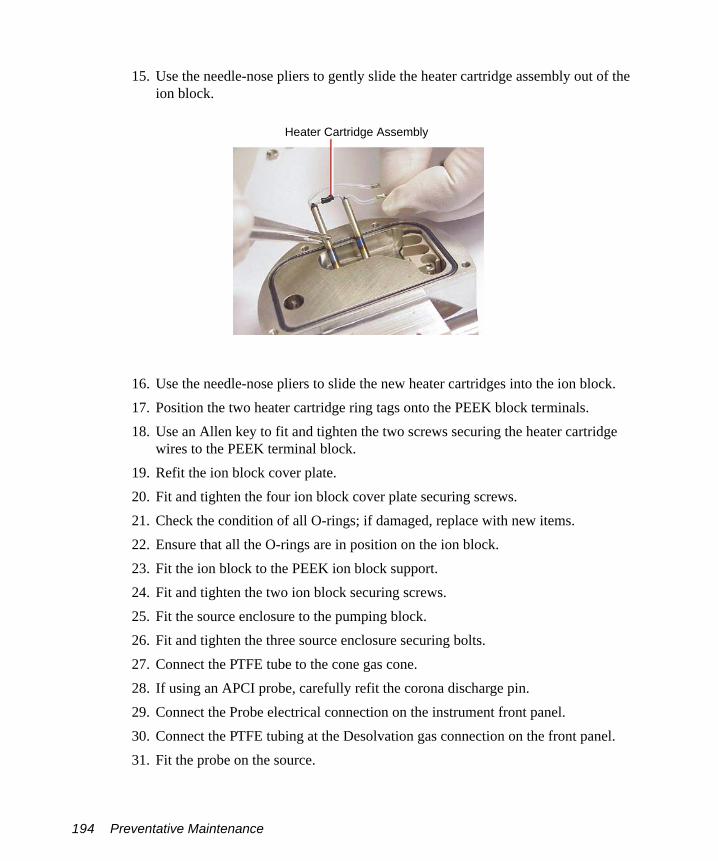
15. Use the needle-nose pliers to gently slide the heater cartridge assembly out of the ion block.
16. Use the needle-nose pliers to slide the new heater cartridges into the ion block.17. Position the two heater cartridge ring tags onto the PEEK block terminals.18. Use an Allen key to fit and tighten the two screws securing the heater cartridge
wires to the PEEK terminal block.19. Refit the ion block cover plate.20. Fit and tighten the four ion block cover plate securing screws.21. Check the condition of all O-rings; if damaged, replace with new items.22. Ensure that all the O-rings are in position on the ion block.23. Fit the ion block to the PEEK ion block support.24. Fit and tighten the two ion block securing screws.25. Fit the source enclosure to the pumping block.26. Fit and tighten the three source enclosure securing bolts.27. Connect the PTFE tube to the cone gas cone.28. If using an APCI probe, carefully refit the corona discharge pin.29. Connect the Probe electrical connection on the instrument front panel.30. Connect the PTFE tubing at the Desolvation gas connection on the front panel.31. Fit the probe on the source.
Heater Cartridge Assembly
194 Preventative Maintenance

8.10 Replacing the ESI Probe Capillary
The stainless steel sample capillary in the ESI probe must be replaced if it becomes blocked and cannot be cleared, or if it becomes contaminated or damaged.
Required Materials• 7-mm hex wrench• ¼-inch (6-mm) hex wrench• 5/16-inch wrench• Needle-nose pliers
Removing the Existing Capillary
1. Follow the procedure in Section 8.5.2, Removing the Probe from the Source, to remove the probe from the source.
Warning: To avoid contamination from previously sprayed sample, always wear gloves when handling the probe. This also prevents finger-grease contaminating the capillary.
Caution: Perform all work on the probe on a clean work bench.
Replacing the ESI Probe Capillary 195

2. Use an Allen key to remove the two probe end cover retaining screws.
3. Remove the end cover.
End Cover Retaining Screws
End Cover
196 Preventative Maintenance

4. Unscrew and remove the nebulizer adjuster knob to reveal a PEEK union/UNF coupling assembly, compression spring, and the capillary.
5. Remove the nebulizer adjuster knob, PEEK union/UNF coupling assembly, compression spring, and capillary from the probe.
6. Remove the PEEK union/UNF coupling assembly, compression spring, and capillary from the nebulizer adjuster knob.
Nebulizer Adjuster Knob
CapillaryCompression Spring
PEEK Union/UNF Assembly
Replacing the ESI Probe Capillary 197

7. Remove the compression spring from the PEEK union/UNF coupling assembly and capillary.
8. Unscrew and remove the knurled collar from the UNF coupling to reveal a conductive sleeve on the capillary.
9. Remove the knurled collar and conductive sleeve from the capillary.10. A locknut is used to secure the PEEK union and UNF coupling. Use the 7-mm
wrench to loosen the locknut.
PEEK Union UNF Coupling
Conductive SleeveKnurled Collar
7-mm Wrench
Locknut
198 Preventative Maintenance

11. Unscrew the PEEK union from the UNF coupling (this connection is finger-tight only).
This reveals a ferrule and liner sleeve:
12. Remove the ferrule and liner sleeve from the capillary.13. Remove the capillary from the UNF coupling.
Ferrule
Liner Sleeve
Replacing the ESI Probe Capillary 199
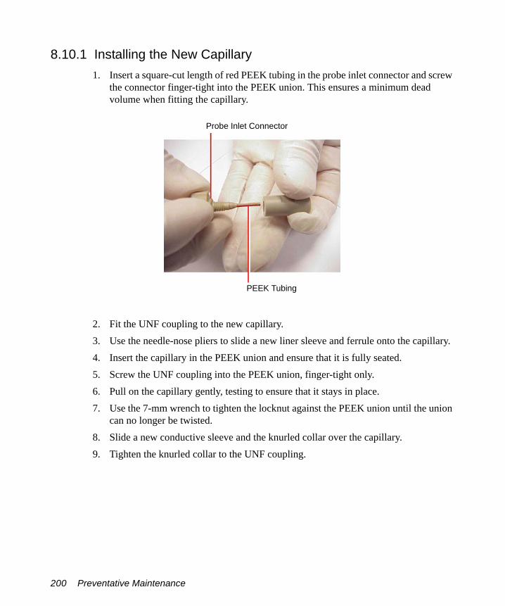
8.10.1 Installing the New Capillary1. Insert a square-cut length of red PEEK tubing in the probe inlet connector and screw
the connector finger-tight into the PEEK union. This ensures a minimum dead volume when fitting the capillary.
2. Fit the UNF coupling to the new capillary.3. Use the needle-nose pliers to slide a new liner sleeve and ferrule onto the capillary.4. Insert the capillary in the PEEK union and ensure that it is fully seated.5. Screw the UNF coupling into the PEEK union, finger-tight only.6. Pull on the capillary gently, testing to ensure that it stays in place.7. Use the 7-mm wrench to tighten the locknut against the PEEK union until the union
can no longer be twisted.8. Slide a new conductive sleeve and the knurled collar over the capillary.9. Tighten the knurled collar to the UNF coupling.
Probe Inlet Connector
PEEK Tubing
200 Preventative Maintenance

10. Check for leaks in the assembly by attaching the free end of the PEEK tubing to an LC pump and pumping through 50:50 acetonitrile:water at 1 mL/min.
If leakage occurs, the connection must be disassembled and remade, and the leak test repeated.
Warning: To avoid possible high-pressure liquid jet spray, wear safety goggles when performing the leak test.
Replacing the ESI Probe Capillary 201

11. When performing the leak test, check the backpressure on the LC pump. This will be high if the capillary is blocked. If this is the case, replace the capillary with a new one.
12. When the leak test has been performed successfully, disconnect the PEEK tubing from the LC pump.
13. Remove the probe inlet connector and PEEK tubing from the PEEK union.14. Refit the PEEK union/UNF coupling assembly to the nebulizer adjuster knob.
Leaking Liquid
202 Preventative Maintenance

15. Refit the compression spring to the capillary and PEEK union/UNF coupling assembly.
16. Use the ¼-inch (6-mm) wrench to remove the probe tip from the probe.
17. Carefully thread the capillary through the probe assembly.
Compression Spring
Probe Tip
Replacing the ESI Probe Capillary 203

18. Ensuring that the locating pin on the UNF coupling engages with the slot in the head of the probe assembly, fit and screw the nebulizer adjuster knob and PEEK union/UNF coupling assembly to the probe assembly. Do not tighten the knob fully.
19. Refit the probe end cover to the probe assembly.20. Refit and tighten the two end cover securing screws.
Locating SlotLocating Pin
(compression Spring removed for clarity)
Locating Pin Locating Slot
204 Preventative Maintenance

21. Refit the probe tip over the capillary and screw the tip onto the probe assembly.
22. If necessary, adjust the probe tip so that the fully extended capillary (when the nebulizer adjuster knob is fully screwed down) protrudes by approximately 1 to 1.5 mm.
23. Use the nebulizer adjuster knob to adjust the capillary so that the capillary protrudes by approximately 0.5 mm from the end of the probe.
24. Attach the nebulizer gas connection and turn on the nitrogen, by clicking on the MassLynx Tune window.
25. Check the probe tip for nitrogen leaks. If a leak is found, replace the probe tip assembly and its O-ring (see Section 8.6, Cleaning or Replacing the ESI Probe Tip).
26. Refit the probe to the instrument.
8.11 Replacing the APCI Probe Capillary
Replace the stainless steel sample capillary in the APCI probe if it becomes blocked and cannot be cleared, or if it becomes contaminated or damaged.
Required Materials• 7-mm hex wrench• ¼-inch (6-mm) hex wrench• 5/16-inch wrench
Capillary Probe Tip
Replacing the APCI Probe Capillary 205
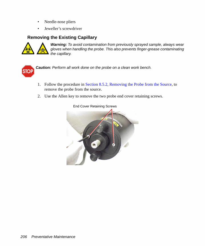
• Needle-nose pliers• Jeweller’s screwdriver
Removing the Existing Capillary
1. Follow the procedure in Section 8.5.2, Removing the Probe from the Source, to remove the probe from the source.
2. Use the Allen key to remove the two probe end cover retaining screws.
Warning: To avoid contamination from previously sprayed sample, always wear gloves when handling the probe. This also prevents finger-grease contaminating the capillary.
Caution: Perform all work done on the probe on a clean work bench.
End Cover Retaining Screws
206 Preventative Maintenance
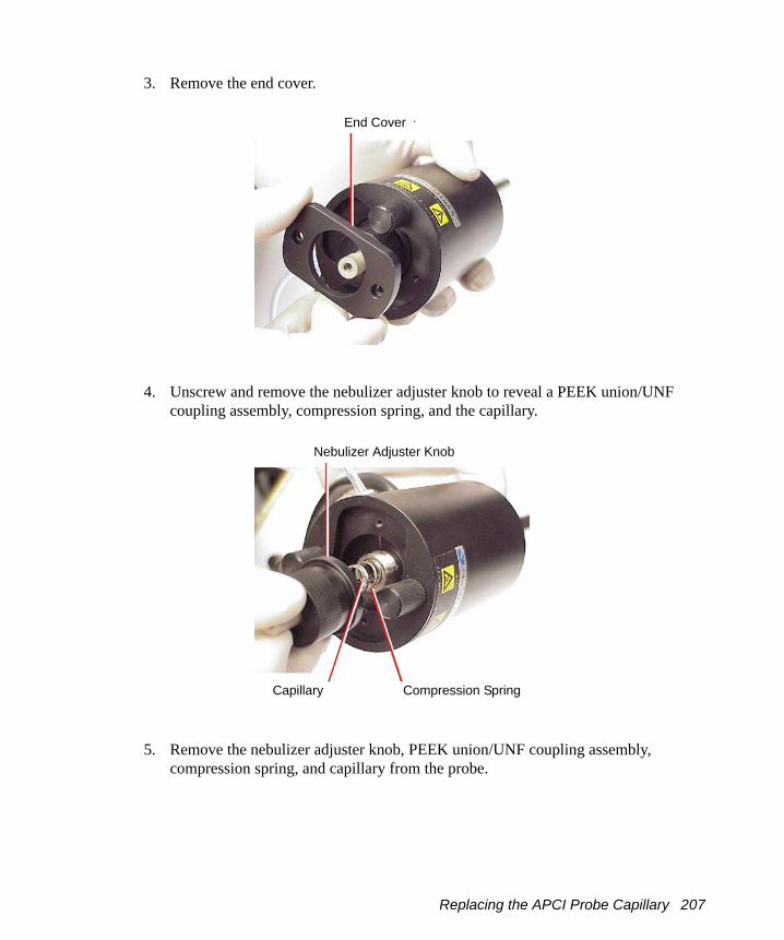
3. Remove the end cover.
4. Unscrew and remove the nebulizer adjuster knob to reveal a PEEK union/UNF coupling assembly, compression spring, and the capillary.
5. Remove the nebulizer adjuster knob, PEEK union/UNF coupling assembly, compression spring, and capillary from the probe.
End Cover
Nebulizer Adjuster Knob
Compression SpringCapillary
Replacing the APCI Probe Capillary 207

6. Remove the PEEK union/UNF coupling assembly, compression spring, and capillary from the nebulizer adjuster knob.
7. Remove the compression spring from the PEEK union/UNF coupling assembly and capillary.
8. A locknut is used to secure the PEEK union and UNF coupling. Use the 7-mm wrench to loosen the locknut.
PEEK Union/UNF Coupling Assembly
7-mm WrenchPEEK Union
Locknut UNF Coupling
208 Preventative Maintenance

9. Unscrew the PEEK union from the UNF coupling (this connection is finger-tight only).
This reveals a ferrule:
10. Remove the ferrule from the capillary.11. Remove the capillary from the UNF coupling.
Ferrule
Replacing the APCI Probe Capillary 209

8.11.1 Installing the New Capillary1. Insert a square-cut length of red PEEK tubing in the probe inlet connector and screw
the connector finger-tight into the PEEK union. This ensures a minimum dead volume when fitting the capillary.
2. Fit the UNF coupling to the new capillary.3. Use the needle-nose pliers to slide a new ferrule onto the capillary.4. Insert the capillary in the PEEK union and ensure that it is fully seated.5. Screw the UNF coupling into the PEEK union, finger-tight only.6. Pull on the capillary gently, testing to ensure that it stays in place.7. Use the 7-mm wrench to tighten the locknut against the PEEK union.
Probe Inlet Connector
PEEK Tubing
210 Preventative Maintenance

8. Check for leaks in the assembly by attaching the free end of the PEEK tubing to an LC pump and pumping through 50:50 acetonitrile:water at 1 mL/min.
If leakage occurs, the connection must be disassembled and remade, and the leak test repeated.
Warning: To avoid possible high-pressure liquid jet spray, wear safety goggles when performing the leak test.
Leaking Liquid
Replacing the APCI Probe Capillary 211

9. When performing the leak test, check the backpressure on the LC pump. This will be high if the capillary is blocked. If this is the case, replace the capillary with a new one.
10. When the leak test has been performed successfully, disconnect the PEEK tubing from the LC pump.
11. Remove the probe inlet connector and PEEK tubing from the PEEK union.12. Use a jeweller’s screwdriver to loosen the two set screws securing the probe heater
cover to the probe.
Set Screw Probe Heater Cover
212 Preventative Maintenance

13. Carefully pull the probe heater cover off the probe, revealing the probe heater.
14. Gripping the heater as shown, carefully pull the probe heater off the probe assembly.
Caution: Take great care not to damage the probe heater electrical wiring either when removing the probe heater cover or while the probe heater is exposed.
Caution: When handling the probe heater, take great care to grip the heater so as not to damage its electrical wiring.
Caution: To avoid damaging the electrical connections to the probe heater, do not twist the heater when removing it from the probe assembly.
Probe Heater Electrical Wiring
Probe Heater
Replacing the APCI Probe Capillary 213

15. Refit the PEEK union/UNF coupling assembly to the nebulizer adjuster knob.16. Refit the compression spring to the capillary and PEEK union/UNF coupling
assembly.17. Carefully thread the capillary through the probe assembly.18. Ensuring that the locating pin on the UNF coupling engages with the slot in the head
of the probe assembly, fit and screw the nebulizer adjuster knob and PEEK union/UNF coupling assembly to the probe assembly. Do not tighten the knob fully.
19. Refit the probe end cover to the probe assembly.20. Refit and tighten the two end cover securing screws.
Caution: When handling the probe heater, take great care to grip the heater so as not to damage its electrical wiring.
Caution: Take great care not to damage the probe heater electrical connections, capillary sleeve, or capillary when fitting the heater over the capillary sleeve.
Locating Pin Locating Slot
214 Preventative Maintenance

21. Carefully slide the probe heater over the capillary sleeve on the probe assembly.
22. Refit the probe heater to the probe assembly, ensuring that the heater is fully seated on the probe assembly.
23. Refit the probe heater cover to the probe assembly.24. Use the jeweller’s screwdriver to tighten the two set screws securing the probe
heater cover to the probe.25. Use the nebulizer adjuster knob to adjust the capillary so that the capillary protrudes
by approximately 0.5 mm from the end of the probe.26. Refit the probe to the instrument.
Caution: To avoid damaging the electrical connections to the probe heater, do not twist the heater when fitting the it to the probe assembly.
Probe Heater Connection
Capillary SleeveCapillary
Replacing the APCI Probe Capillary 215

8.12 Replacing the APCI Probe Heater
Replace the APCI probe heater if it fails to heat.
Required MaterialsJeweller’s screwdriver
Procedure
1. Use the jeweller’s screwdriver to loosen the two set screws securing the probe heater cover to the probe.
Warning: To avoid contamination from previously sprayed sample, always wear gloves when handling the probe. This also prevents finger-grease contaminating the capillary.
Caution: Perform all work on the probe on a clean work bench.
Caution: Take great care not to damage the probe heater electrical wiring either when removing the probe heater cover, or whilst the probe heater is exposed.
Set Screw Probe Heater Cover
216 Preventative Maintenance
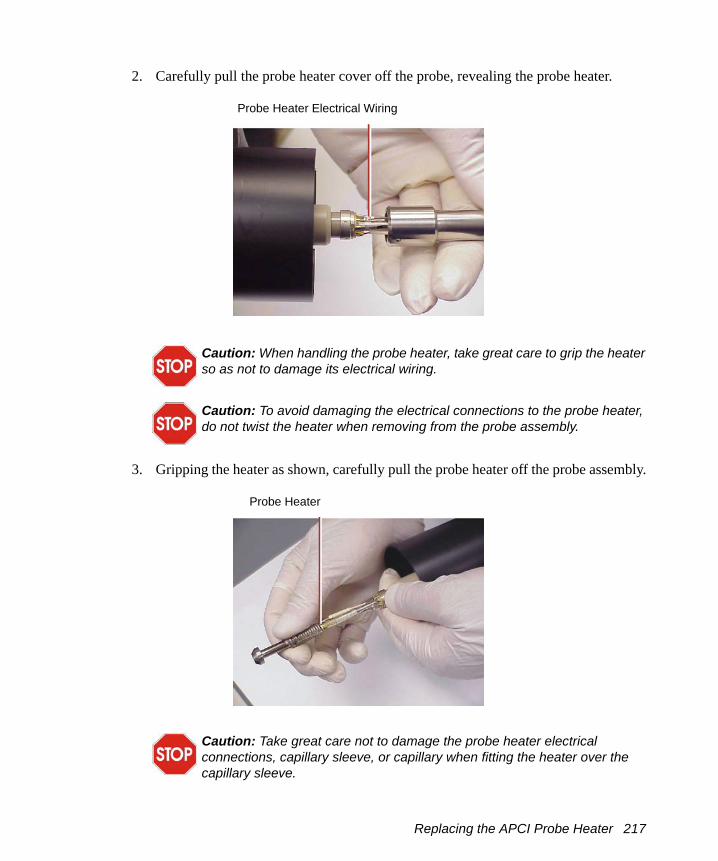
2. Carefully pull the probe heater cover off the probe, revealing the probe heater.
3. Gripping the heater as shown, carefully pull the probe heater off the probe assembly.
Caution: When handling the probe heater, take great care to grip the heater so as not to damage its electrical wiring.
Caution: To avoid damaging the electrical connections to the probe heater, do not twist the heater when removing from the probe assembly.
Caution: Take great care not to damage the probe heater electrical connections, capillary sleeve, or capillary when fitting the heater over the capillary sleeve.
Probe Heater Electrical Wiring
Probe Heater
Replacing the APCI Probe Heater 217

4. Carefully slide the new probe heater over the capillary sleeve on the probe assembly.
5. Refit the probe heater to the probe assembly, ensuring that the heater is fully seated on the probe assembly.
6. Refit the probe heater cover to the probe assembly.7. Use the jeweller’s screwdriver to tighten the two set screws securing the probe
heater cover to the probe.
Caution: To avoid damaging the electrical connections to the probe heater, do not twist the heater when fitting the heater to the probe assembly.
Probe Heater Connections
Capillary Capillary Sleeve
218 Preventative Maintenance

8. Use the nebulizer adjuster knob to adjust the capillary so that the capillary protrudes by approximately 0.5 mm from the end of the probe.
9. Refit the probe to the instrument.
8.13 Maintaining the APPI Lamp
8.13.1 Changing the Lamp Bulb
1. On the MassLynx window, click Press for Standby and confirm the adjacent instrument status indicator shows red.
2. On the Tune window, set Source Temp (°C) to 60.3. Ensure that the Repeller (kV) readback is 0.4. Open the source enclosure door.5. Retract and remove the APPI lamp drive assembly from the source enclosure.6. Remove the cover cap from the back of the lamp drive assembly (Figure 8-9).7. Insert an appropriate tool (for example, a length of nylon tube) through the back of
the lamp drive assembly, and push the bulb forward.8. Withdraw the bulb from the lamp drive assembly.9. Insert the new bulb into the lamp drive assembly.10. Refit the cover cap to the lamp drive assembly.
Warning: To avoid electric shock, ensure that the instrument is in standby mode before commencing this procedure.
Warning: To avoid contamination with toxic and biohazardous materials, wear rubber gloves at all times while handling the components.
Maintaining the APPI Lamp 219

Figure 8-9 Changing the APPI Lamp Bulb
8.13.2 Cleaning the Lamp Window
The transmission of the high-energy photons responsible for APPI relies on the cleanliness of the magnesium fluoride lamp window. Clean the window with methanol or isopropyl alcohol, using a lint-free cloth, to keep the window surface clear of contamination and avoid reduced sensitivity.
Warning: To avoid contamination with toxic and biohazardous materials, wear rubber gloves at all times while handling the components.
Nylon Tube
Cover Cap (Removed from the Lamp Drive Assembly)
APPI Lamp Bulb
220 Preventative Maintenance
8.14 Performing LockSpray Maintenance
8.14.1 LockSpray
Cleaning the Oscillating Baffle1. Unplug the LockSpray motor from the instrument.2. Remove the LockSpray motor from the source.3. Put the baffle in a beaker of 50:50 acetonitrile:water or 50:50 methanol:water with
1% formic acid and place in an ultrasonic bath for 15 minutes. Rinse with water after cleaning.
4. When replacing the baffle, ensure it locates correctly on the square end of the shaft and check that it is oriented such that the reference and analyte sprays are selected correctly from the Tune window.
Replacing the Reference Probe CapillaryIf the LockSpray reference probe is blocked, replace its stainless steel capillary.
Before carrying out this operation:
1. Switch the instrument into Standby.
2. Disconnect the high voltage cable from the probe.
3. Disconnect the nebulizer gas line, and remove the probe from the source.
Warning: Always remove the high voltage connection before attempting any probe maintenance.
Warning: Allow the probe to cool down before working on it.
Performing LockSpray Maintenance 221

Removing the Steel Capillary1. Remove the two thumbscrews and the syringe line.
2. Unscrew the coupling and withdraw from the probe.
Thumbscrews Syringe Line
Coupling
Withdrawn Coupling
222 Preventative Maintenance

3. Unscrew the elbow from the coupling, pull out ferrule and pull out the steel capillary and tubing sleeve from the ferrule
Reassembling the Probe1. Unscrew and remove the probe tip.
2. Thread the new steel capillary through the blue tubing sleeve, and push the tubing sleeve through the ferrule.
Elbow
Steel Capillary Ferrule
Tubing Sleeve
Probe Tip
Performing LockSpray Maintenance 223

3. Use a nut and the elbow to clamp the ferrule to the liner. Be sure to push the liner and steel capillary all the way into the elbow as you tighten the nut. Tighten until the liner is clamped, but take care not to overtighten it.
4. Remove the nut - the tubing sleeve should remain clamped within the ferrule - and replace with the coupling.
5. Screw the elbow into the coupling, whilst ensuring that the steel capillary is pushed all the way in. Tighten until the steel capillary is gripped. Do not overtighten.
Nut
ElbowFerrule and Liner
224 Preventative Maintenance

6. Thread the conductive sleeve over the steel capillary and slide to the coupling.
7. Thread the steel capillary through the probe body. Take care not to bend the capillary. Screw the coupling all the way in, then back off until the elbow is at a convenient angle.
8. Carefully thread the steel capillary through the probe tip, and then screw the tip into the probe shaft until about 0.5 mm of steel capillary is showing.
9. Attach the fused silica syringe line using a green tubing sleeve. Push the tubing sleeve and fused silica capillary into the elbow as you tighten the nut. Tighten until
Conductive Sleeve
Steel Capillary
Performing LockSpray Maintenance 225
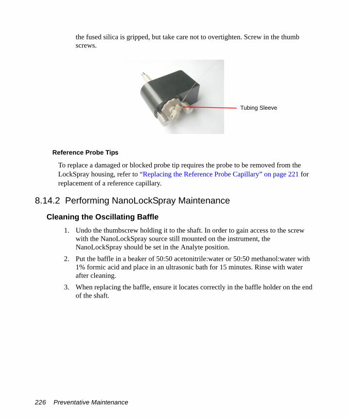
the fused silica is gripped, but take care not to overtighten. Screw in the thumb screws.
Reference Probe Tips
To replace a damaged or blocked probe tip requires the probe to be removed from the LockSpray housing, refer to “Replacing the Reference Probe Capillary” on page 221 for replacement of a reference capillary.
8.14.2 Performing NanoLockSpray Maintenance
Cleaning the Oscillating Baffle 1. Undo the thumbscrew holding it to the shaft. In order to gain access to the screw
with the NanoLockSpray source still mounted on the instrument, the NanoLockSpray should be set in the Analyte position.
2. Put the baffle in a beaker of 50:50 acetonitrile:water or 50:50 methanol:water with 1% formic acid and place in an ultrasonic bath for 15 minutes. Rinse with water after cleaning.
3. When replacing the baffle, ensure it locates correctly in the baffle holder on the end of the shaft.
Tubing Sleeve
226 Preventative Maintenance

Replacing the Reference Probe Capillary If the silica reference capillary is blocked, or if it is contaminated or damaged, replace it.
1. Disconnect the probe:
a. Disconnect the reference line from the probe and remove the finger-tight nut. b. Disconnect the HV cable from the reference probe at the instrument front panel. c. Disconnect the HV cable from the analyte probe at the reference probe connector.d. Disconnect the reference probe nebulizing gas tube (Figure 8-10).
Figure 8-10 Reference Probe Nebulizing Gas Tube
2. Remove the reference probe cover and undo the two bolts holding the reference probe to the NanoLockSpray housing and carefully withdraw the probe.
3. Remove the nebulizing gas line from the tee:a. Loosen the grub screws that secure the Tee and Union, remove the tee and union
from the probe holder.
Warning: Always remove the high voltage connection before attempting any probe maintenance.
Performing LockSpray Maintenance 227

Figure 8-11 Removing the Fused Silica and PTFE Sleeves
b. Undo the tee nut and union nut marked A (Figure 8-11) and remove the fused silica and the PTFE sleeves.
c. Remove the headless sealtight nut and ferrule and 75-µm i.d. fused silica. d. Discard both pieces fused silica.
4. Prepare the 20-µm i.d. fused silica:
Figure 8-12 Preparing the Fused Silica
a. Cut approximately 15 cm of 20-µm i.d. fused silica and thread it into the sleeve making sure that the end of the silica is flush with the end of the sleeve (Figure 8-12).
b. Insert the sleeve and silica into the union (Figure 8-13).
Figure 8-13 Sleeve and 20-µm Silica in Union
228 Preventative Maintenance

c. Push the silica through the union and progressively tighten the union nut and test the tightness of its grip on the silica.
d. Once the grip is sufficient to restrict movement, remove the nut and move the silica so it is flush with the edge of the PTFE sleeve.
e. Tighten the nut to lock the fused silica in place. f. Thread the 20-µm i.d. fused silica through the tee piece and the nebulizing
capillary. Tighten the tee nut holding the silica sleeve so that it is finger tight and make sure that the fused silica is free to move though the tee (Figure 8-14).
Figure 8-14 Tee Piece
g. Thread the fused silica through the tee piece until the Valco union is close to the tee piece.
5. Prepare the 75-µm i.d. fused silica.
Figure 8-15 Preparing the 75-µm Fused Silica
a. Cut a long length (>30 cm) of 75-µm i.d. fused silica. Ensure that the silica has been cut squarely to reduce dead space.
b. Thread the 75-µm i.d. fused silica through the sleeve making sure that the fused silica end is flush with the end of the sleeve (Figure 8-15).
Figure 8-16 Sleeve and 75-µm Silica in the Union
Performing LockSpray Maintenance 229

c. Make sure that there is excess PEEK exposed to ensure minimum dead space and insert the silica and nut into the other side of the Valco union (Figure 8-16).
d. Tighten using the nut extender tool. 6. Thread tube assembly through the probe housing by threading the whole assembly
through the probe assembly and seat the tee piece into its holder and tightening the grub screw to hold it into place (Figure 8-17)
Figure 8-17 Tube Assembly
7. Set the silica length:a. Position the union so that it is close to the tee and cut the fused silica near to the
nebulizing capillary.
Figure 8-18 Cutting the Fused Capillary Close to the Nebulizing Capillary
b. Reposition the union so that approximately 0.5 to 1 mm of fused silica protrudes out of the nebulizing capillary.
c. Tighten the grub screw above the Valco union to secure it in place and also tighten the gas seal nut on the tee to secure the fused silica (Figure 8-18).
230 Preventative Maintenance

Figure 8-19 Reconnecting the Nebulizing Gas
d. Reconnect the nebulizing gas tube and retighten the nut (Figure 8-19). e. Replace the probe cover and tighten the grub screw to clamp the LC union. f. Reconnect the gas and lines (Figure 8-19).
8.15 Performing MUX-technology Maintenance
8.15.1 Cleaning the Sampling Rotor Assembly
OverviewClean the MUX flange sampling rotor assembly (Figure 8-20) when it is visibly fouled.
To clean the sampling rotor assembly:
1. Remove the MUX flange from the LCT Premier (see Section 8.15.1.1) 2. Disassemble the sampling rotor assembly (see Section 8.15.1.2).
Performing MUX-technology Maintenance 231

Figure 8-20 5 and 9-way MUX Flanges
3. Clean the sampling rotor, spacers and gas tubes (see Section 8.15.1.3).4. Reassemble the sampling rotor assembly and refit the MUX flange interface to the
MUX enclosure (see Section 8.15.2).
Required Materials• Rubber gloves• Flat-blade screwdriver• Appropriately sized glass vessels, in which to completely immerse components
when cleaning. Use only glassware not previously cleaned with surfactants.• HPLC-grade methanol• HPLC-grade water• Ultrasonic bath• Source of oil-free, inert gas (nitrogen or helium) for drying (air-drying optional).• Lint-free paper towels
Sample Rotors
Probe Tips
232 Preventative Maintenance

8.15.1.1 Removing the MUX Flange1. Stop the liquid flow to the source. 2. On the Tune window set the Desolvation temperature to 20°C. 3. Wait until the Desolvation readback indicates that this temperature has been
reached.4. Click Standby.
5. Remove the Desolvation Gas Heater.
6. Click to switch the API gas off.7. Disconnect these items:
a. The motor cable from the Front Panel.b. The high voltage cable from the MUX flange.c. The liquid inlet lines from the PEEK unions on the MUX flange.d. The nebulizer gas tube from the MUX flange.e. The desolvation gas heater from the source housing.
8. Remove the four retaining screws and ease the flange away from the MUX enclosure.
9. Move the flange upwards so that the probe support segment moves into the window region, and then slowly rotate the base of the flange away from the housing.
10. Lower the flange so that the support segment clears the housing aperture and remove it slowly.
Warning: Handle all components carefully as they may be hot, and contaminated with residual solvents and possibly toxic materials.
Warning: To avoid exposure to high voltages the end flange should not be removed before the MUX flange.
Caution: To prevent damage to the stainless steel capillaries contained within the PTFE tubing, remove the MUX flange extremely carefully.
Performing MUX-technology Maintenance 233

8.15.1.2 Disassembling the Sampling Rotor Assembly
1. Remove the MUX flange from the LCT Premier (see Section 8.15.1.1).2. Remove the two screws securing the sampling rotor to the outer chamber
(Figure 8-21).
Figure 8-21 Sampling Rotor Assembly
3. Carefully ease the sampling rotor off the gas tubes.4. Remove the gas tubes and spacers from the outer chamber.5. Clean the sampling rotor, gas tubes and spacers (Section 8.15.1.3).
Warning: To avoid possible electric shock, ensure that the instrument is in standby mode before commencing this procedure.
Warning: The MUX-technologies interface may be contaminated with toxic materials. Always wear rubber gloves while handling its components.
Screws
Spacers
Gas Tubes
Sampling Rotor
Outer Chamber
234 Preventative Maintenance

8.15.1.3 Cleaning the Sampling Rotor Assembly Components
1. Immerse the sampling rotor assembly components in a glass vessel containing methanol:water (1:1).
2. Place the vessel in the ultrasonic bath for 30 minutes.3. Carefully remove the components from the vessel and blow-dry using inert, oil-free
gas.Alternatively, place the components on lint-free towels and allow to air dry. Wipe off any water spots with a lint-free cloth.
8.15.2 Reassembling the Sampling Rotor Assembly
1. Refit the gas tubes and spacers to the outer chamber.2. Align the holes in the sampling rotor with the gas tubes and fit the rotor onto the gas
tubes while ensuring that the spacers are correctly located.3. Refit the two screws securing the sampling rotor to the outer chamber.4. Refit the MUX flange to the MUX enclosure (see Section 7.2).
8.15.3 Replacing the ElectroSpray Probe Tip1. Remove the MUX flange from the MUX enclosure (see Section 8.15.1.1).
Warning: The sampling rotor assembly components may be contaminated with toxic materials. Always wear rubber gloves at all times while handling these components.
Warning: The MUX-technologies interface, may be contaminated with toxic materials. Always wear rubber gloves at all times while handling the components.
Performing MUX-technology Maintenance 235

Figure 8-22 Sample Rotor and Probe Tips on MUX Flange
2. Remove the sampling rotor (Figure 8-22) from the MUX flange (see Section 8.15.1.2).
3. Using the wrench provided, unscrew and carefully remove the electrospray probe tip from the probe support segment (Figure 8-22).
4. Carefully slide the new electrospray probe tip over the stainless steel capillary and fit it to the probe support segment.
5. Adjust the probe tip so that the sample capillary is protruding by approximately 0.5 mm from the end of the tip.
6. Refit the sampling rotor to the MUX flange (see Section 8.15.2).7. Align the sampling rotor sample apertures with the probe tip and look through the
them to check whether the capillary is central and straight in the probe tip (Figure 8-23). A magnifying glass may be used, if necessary.
Note: Tweezers may be used to apply light pressure to the capillary to adjust its position.
SampleRotor
Probe Tip
ProbeSupport
236 Preventative Maintenance

Figure 8-23 Aligning the Capillary
8. Refit the MUX flange to the MUX enclosure (see Section 7.2).
8.15.4 Replacing a Sample Capillary
If a sample capillary becomes blocked, or is damaged, it may be replaced as follows:
1. Remove the MUX flange from the MUX enclosure (see Section 8.15.1.1).2. Remove the sampling rotor (Figure 8-22) from the MUX flange (see
Section 8.15.1.2).3. Unscrew the hexagonal nut from the probe support segment (Figures 8-24
and 8-25).
Warning: The interface may be contaminated with biologically hazardous materials. Always wear rubber gloves while handling the components.
ElectroSpray Tip Sampling Aperture
Sampling Rotor
ElectroSpray Probe Tip
Performing MUX-technology Maintenance 237

Figure 8-24 Unscrewing the hexagonal Nut
Figure 8-25 Probe Support Segment Assembly
Hexagonal Nut
PEEK Union
Hexagonal Nut
PTFE Sleeve
Ferrule
Probe Support Segment
Sample Capillary
238 Preventative Maintenance

4. Unscrew the finger-tight PEEK fitting from the union passing through the MUX flange (Figures 8-24 and 8-26).
5. Remove the PEEK fitting and PTFE protective sleeve from the sample capillary (Figure 8-26).
Figure 8-26 Probe Support Assembly
6. Slide the sample capillary out of the PTFE sleeve seated in the probe support segment.
7. Slide the PTFE sleeve out of the probe support segment.
Note: If the graphite ferrule is stuck in the probe support segment, use a screwdriver, or similar object, to lever it out.
8. Align the sampling rotor’s sample apertures with the probe tip.9. Feed the new sample capillary through the sampling rotor sample apertures and
probe tip. Continue feeding the capillary through until approximately 0.5 mm of capillary is left protruding from the probe tip.
Caution: If using a tool to remove the ferrule from the PEEK fitting, take care not to damage the fitting.
PTFE Sleeve (93 mm long)
PTFE Sleeve (30 mm long)
Sample Capillary
Protective Sleeve
PEEK Fitting
Union
Performing MUX-technology Maintenance 239

10. Slide a 93 mm length of 1/16 inch o.d., 0.010 inch i.d. PTFE sleeve over the free end of the sample capillary. Feed this into the probe support segment until it is firmly located in the segment (Figure 8-27).
Figure 8-27 Sample Capillary, PTFE Sleeve, Nut and Ferrule
11. Slide a graphite ferrule and the hexagonal nut over the PTFE sleeve (Figure 8-27).
12. Ensure that approximately 0.5 mm of sample capillary is protruding from the probe tip, then tighten the nut onto the probe support segment sufficiently to grip the ferrule onto the sample capillary.
13. Slide the PTFE protective sleeve over the sample capillary and PTFE sleeve.14. Ensure that the 30 mm long 1/16 inch o.d., 0.010 inch i.d. PTFE sleeve is located in
the PEEK fitting.15. Slide the PEEK fitting over the capillary.16. Slide the protective sleeve over the joint between the two PTFE sleeves; this
prevents the sample capillary kinking at this point and ensure the sample capillary protrudes a few millimeters through the PEEK Union (Figure 8-28).
Caution: Ensure that the ferrule is not over-compressed when tightening the hexagonal nut onto the probe support segment.
Sample Capillary
PTFE Sleeve
Hexagonal Nut
Graphite Ferrule
240 Preventative Maintenance

Figure 8-28 PEEK Union Showing Protruding Capillary
17. Locate the PEEK fitting within the union on the MUX flange, making sure the sample capillary still protrudes through the union.
18. To ensure that the sample capillary is fully butted up in the union passing through the MUX flange (Figure 8-29), use another PEEK fitting from the other side to locate the capillary precisely (Figure 8-30)
Figure 8-29 PEEK Fitting and Union
Protective SleevePEEK Fitting
Sample Capillary
PEEK Fitting
PTFE Sleeve
Sample Capillary
Union
Performing MUX-technology Maintenance 241
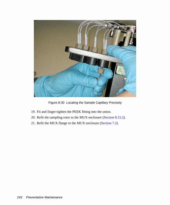
Figure 8-30 Locating the Sample Capillary Precisely
19. Fit and finger-tighten the PEEK fitting into the union.20. Refit the sampling rotor to the MUX enclosure (Section 8.15.2).21. Refit the MUX flange to the MUX enclosure (Section 7.2).
242 Preventative Maintenance
Chapter 9 Fault Finding
9.1 Fault Finding
Most faults can be traced to a malfunction of the ion source or inlet system. On systems equipped with more than one source, this can often be confirmed by changing sources to see if the fault moves with the source.
Should a fault occur soon after a part of the system has been repaired or otherwise disturbed, first ensure that this part has been correctly refitted and adjusted, and that adjacent components have not been inadvertently disturbed.
9.1.1 Instrument Stops Responding to Commands from MassLynx.The first thing to try is to exit MassLynx and then restart the application. If this fails a reboot will be necessary.
There are three levels of reboot, with the levels required being dependent on the nature of the problem. Before rebooting you must determine whether a communications (comms) link exists between the MassLynx PC and the embedded PC (EPC)
Note: It's best to exit MassLynx before doing a reboot.
Testing Communications between MassLynx PC and the EPCFrom Windows, select Start > Run and type ping -t epc in the Run dialog box.
The following messages appear if the comms link is OK.
Fault Finding 243

The following messages will appear if there is no PC to EPC comms. This indicates a test failure.
Note: The comms test will fail during an EPC reboot. The comms link will recover with the completion of the reboot. If the comms link does not recover check the network cable linking the MassLynx PC with the PC Link socket at the rear of the instrument.
RebootingThere are three level of reboot that you can try.
1. From Telnet2. By resetting the EPC3. Switching the instrument off.
However, success depends on the nature of the problem, you should therefore try all three in the order listed here, until you succeed
From TELNET
1. From Windows, select Start > Run and type telnet epc in the Run dialog box.2. Type reboot at the -> prompt in the telnet epc window. This will reload the EPC
software.If the -> prompt is absent then an embedded PC reset will be necessary.
Note: The full reboot will take about 3 minutes to complete.
Embedded PC Reset
Push the embedded PC reset button on the user I/O PCB (see Section 1.7.5, Rear Interface Panel). This will reboot the EPC operating system and reload the EPC software.
The full reboot will take about 3 minutes to complete.
If this doesn't fix the problem then a full power-off reboot will probably be necessary
Fault Finding 244

Power Off
Switch off the electronics power at the rear of the instrument. Wait 5 seconds, and switch back on. This will reboot both the embedded PC and the control PCB.
The pumps will shut down while the electronics switch is off, but will start again when the power is restored.
Note: Pumping will resume only if the turbo is at greater than 50% speed. If the turbo falls to less than 50% speed, the system will power up to a vented state, with the pumps off and soft vent on.
9.1.2 No BeamConsult the relevant chapters of this manual and ensure the system meets these conditions:
• Normal tuning parameters are set and, where applicable, readback values are acceptable.
• All necessary cables have been correctly attached to the source and probe.• Solvent is reaching the probe tip and the solvent flow rate is as required.
Note: For solvent flow rates below 100 µL/min, it may be necessary to temporarily turn off the nebulizing gas and remove the probe from the source to allow the solvent to be seen at the probe tip.
• The desolvation and nebulizer gas are flowing and set according to the correct flow rates.
• The source has been assembled correctly and is clean.
• The source isolation valve is open.
If, after performing the above checks, the beam is still absent.
1. Acquire TOF data with a mass range extending down to m/z 20.2. Check that there is an interference ‘peak’ at approximately m/z 55 due to the pusher
pulse being switched off.
Note: If this interference peak is not present, either the pusher is not pulsing or the output from the detector is not reaching the TDC (time-to-digital converter).
If the pusher interference peak is not present, no data will be acquired.
9.1.3 Unsteady BeamRefer to the relevant chapters of this manual and check that:
Fault Finding 245

• Capillary (electrospray) and Sample Cone are tuned correctly.• The capillary is not protruding too far from the end of the probe.• The probe is not too far into the source.• The flow of solvent from the HPLC pump is correct and steady.
Note: To do this, remove the probe, degas the solvent, increase the flow rate for several minutes to purge any trapped air then reset and re-measure the flow rate.
• Solvents have been adequately degassed.• The nitrogen flow of desolvation and nebulizer gas is steady. The nitrogen supply
pressure should be 7 bar (100 psi) ±10%.• Desolvation Temp is not set too high for the liquid flow rate used.
Note: High temperatures can vaporize solvent within the electrospray probe.
Should the preceding checks fail to reveal the cause of the problem, proceed to the following section.
9.1.4 High BackpressureFor electrospray, a higher than normal backpressure readout on the HPLC pump, together with a slowing of the actual solvent flow at the probe tip, can imply that there is a blockage in the capillary transfer line or injection loop due to particulate matter from the sample.
To clear the blockage:
Remove the probe from the source and increase the solvent flow to 50 µL/min to remove the blockage.
Note: Often, injections of neat formic acid help to redissolve any solute which has precipitated out of solution.
If the blockage cannot be cleared in this fashion:
1. Remove the finger-tight nut and tubing from the back of the probe.2. If the back pressure remains high, replace the tubing with new tubing (or first try
removing both ends of the tube).3. If the back pressure falls, replace the stainless steel sample tube inside the probe (or
try reversing the tube to blow out any blockage).4. Reconnect the tubing to the probe.
The solvent flow can now be readjusted and the probe replaced into the source.
Fault Finding 246

Note: To check the flow rate from the solvent delivery system, fill a syringe barrel or a graduated glass capillary with the liquid emerging from the probe tip, and time a known volume, say 10 µL.
Once the rate has been measured and set, note the back pressure readout on the pump, as fluctuation of this reading can indicate problems with the solvent flow.
For APCI a higher than normal back pressure readout on the HPLC pump can imply that, after a long period of use, the filter pad requires replacement.
9.1.5 Loss of SensitivityAs the ion source becomes dirty after prolonged use, the performance will degrade.
Unstable or reduced ion currents indicate that the source needs cleaning. The usual remedy is to clean the source as described in Section 8.5.8, Cleaning the Source Components.
An increase in the analyzer pressure above 4e-6 mbar can also cause loss of sensitivity, although the pressure at which this occurs will be sample dependent.
9.1.6 Incorrect Isotope DistributionsIncorrect isotope distributions can be caused by:
• The TDC Signal threshold (mV) threshold being set too high• A faulty MCP• Saturated Signal
A faulty attenuator can fail so that they are open circuit (no beam or pusher interference ‘peak’ present), or they can fail such that they stop attenuating. The latter failure mode gives rise to incorrect isotope distributions.When the attenuator fails in this way, you can increase the signal threshold to a significantly higher value than that used previously without reducing the beam intensity.
Note: In normal operation, setting the TDC Signal threshold above 200 or 250 mV will start to reduce the beam intensity. If the attenuator has failed, you can increase the TDC Signal threshold to 500 mV or higher before the beam intensity is reduced.
9.1.7 High Noise LevelsHigh noise levels can either be chemical or electronic in nature.
Fault Finding 247

Chemical NoiseChemical noise usually originates from contaminated samples, solvents, or source gases.
It can be distinguished from electronic noise simply by stopping source ionization. If no liquid or gases are entering the source and all the source voltages are set to zero, then the remaining noise will be electronic in nature.
Electronic NoiseElectronic noise can be caused by setting the signal threshold too low. The microchannel plate detector can be damaged by failure to properly condition the detector after venting of the system to atmosphere. If the detector is producing micro discharges, excessive noise is apparent on the baseline of mass spectra in the absence of any ion beam. Reducing the detector voltage will reduce the number of discharges and also reduce the noise.
9.2 LockSpray Fault Finding
The following faults and solutions apply to LockSpray and NanoLockSpray:
• If the Tune window “times out” when attempting to find either the analyte or reference spray, ensure that the motor cable is connected.
• If the signals from either spray are unstable, or the signal changes when operating, it is possible that the baffle may need cleaning (see “Cleaning the Oscillating Baffle” on page 221 or page 226) or that the sprayer is discharging to the baffle indicates the need to reduce the capillary voltage.
General maintenance and fault finding for a ZSpray source operating in the electrospray mode are found in the appropriate sections of this chapter.
9.3 MUX Fault Finding
9.3.1 Checking the Relative Sensitivity of Each SprayTo assess the relative performance of each sprayer, a sample solution can be infused into each line sequentially and the signal intensities compared. If the sensitivity of any sprayer is outside the specified range (±30%), the following should be checked:
• There are no liquid leaks.
248 Fault Finding

• If sample flow splitters are used, they are delivering approximately the same flow rate to each channel.
• The probe tip is correctly set (see Section 8.15.3).• The sample capillary is not wholly or partially blocked.• The nebulizer gas flows are similar between sprays.
If a disparity remains after checking the above, fit a new sample capillary (see Section 8.15.4).
9.3.2 Sampling Rotor does not RotateEnsure the motor cable is connected to the motor connector on the instrument front panel.
9.3.3 Tune Window Readbacks Indicate no Voltages Present Ensure the desolvation gas heater is correctly positioned, with the sprung pins contacting the stainless steel earth plate on the ned flange.
9.4 Contacting Waters
You can easily correct many problems with the LCT Premier. However, if this is not the case, you must contact Waters.
Customers in the USA and Canada should report maintenance problems they cannot resolve to Waters Technical Service (800 252-4752). All others should visit http://www.waters.com and click Offices, or phone their local Waters subsidiary or Waters corporate headquarters at 34 Maple Street, Milford, MA 01757, USA.
When contacting Waters, have the following information available:
• The nature of the symptom• The LCT Premier serial number
Depending on the nature of the fault, it may also be useful to have the following information available:
• Details about the flow rate, mobile phases, and sample concentrations• Tune window settings• The Software version update reference
Contacting Waters 249

250 Fault Finding

Appendix A Starting Up and Shutting Down the Instrument
A.1 Starting the LCT Premier
1. Turn on the power switch located on the front-right side of the instrument front panel (see Section 1.6, Front Panel).
2. Allow 3 minutes for the embedded PC to initialize.3. Start the MassLynx software. The MassLynx window appears and the word Ready
appears in the status bar at the bottom of the window.4. Click the Instrument shortcut bar MS Tune icon to open the Tune window.5. Select Options > Pump.6. Click the Diagnostics tab.
Note: If the Diagnostics tab is not present, select Options > View Diagnostics Page.
7. Monitor the Turbo Speeds. These parameters should reach 98 to 100% within approximately 5 minutes of selecting Options > Pump.
8. Ensure that the instrument has pumped sufficiently such that the Vacuum LED on the front panel is steady green (see Section 1.3, The Vacuum System). The mass spectrometer is sufficiently evacuated to enable operation in three hours.
Starting the LCT Premier 251

A.2 Shutting Down the LCT Premier
A.2.1 Emergency Instrument Shutdown
In the event of having to shut down the instrument in an emergency, switch off the power at the wall mounted isolation switch(es), if fitted. If not, switch off the System Power switch located on the rear of the instrument (see Section 1.7, Rear Panel) and turn off all peripherals.
Note: A loss of data is likely.
Note: If control of the instrument is lost through MassLynx, you can place it in Standby by pressing the Standby switch on the front of the instrument (see Section 1.6, Front Panel).
A.2.2 Overnight Instrument ShutdownWhen the instrument is to be left unattended for a long time, for example, overnight or at weekends, proceed as follows:
1. On the MassLynx Tune window Source tab, switch of the API gas and stop the syringe.
2. If required, click Press for Standby to switch the instrument out of Operate mode.
Note: It is not necessary to switch the instrument out of Operate mode. However, this is acceptable provided that the instrument warm-up time is considered when restarting analysis.
A.2.3 Complete Instrument Shutdown1. On the Tune window, click Press for Standby.2. Select Vacuum > Vent.3. Select Vent Instrument, a message confirms the vent command.4. Click OK. The turbomolecular pump is switched off. When the turbomolecular
pump has run down to half its normal operating speed, the vent valve is opened and the instrument is automatically vented. The Vacuum LED will switch off after changing from green to amber.
5. Exit MassLynx.
Warning: The power switch does not isolate the instrument from the mains power supply. Unplug the mains power from the rear of the instrument to isolate the instrument from the mains power supply.
252 Starting Up and Shutting Down the Instrument

6. Shut down the PC.7. Switch off all peripherals.8. Switch off the System Power switch located on the rear panel (see Section 1.7, Rear
Panel).
A.3 Automatic Startup and Shutdown
MassLynx has automatic Startup and Shutdown files. They are found in the C:\MassLynx\Shutdown directory and are called ShutDownxxx.acl and StartUpxxx.acl, where xxx refers to the instrument configuration. E.g. ShutDownESI_ACE.acl for an instrument configured as an ACE system.
A.3.1 The Shutdown Editor The Shutdown Editor allows automatic startup and shutdown procedures to be modified or created. These can be run automatically before or after a batch if you select the relevant check boxes in the Batch Control frame of the Shutdown Page (Section A.3.3).
Select Edit Shutdown or Startup from the MassLynx Instrument Shortcut Bar to open the Shutdown Editor. It contains the Shutdown page (described in Section A.3.3 on page 254) and the Auto Control Tasks page (described in Section A.3.4 on page 258).
Automatic Startup and Shutdown 253

A.3.2 The Shutdown Editor Toolbar
A.3.3 Shutdown PageSelect Edit Shutdown or Startup from the MassLynx Instrument Shortcut bar.
By default the Shutdown page is appears (Figure A-1) with the following parameters.
Toolbar Button
Menu Equivalent Purpose
File > New Create a new Startup or Shutdown file.
File > Open Open an existing Startup or Shutdown file.
File > Save or Save As
Save a Startup or Shutdown file.
File > Print Print a Startup or Shutdown file.
Control List > Run List
Run a Startup or Shutdown file.
Control List > Stop List
Stop a Startup or Shutdown file.
Enable startup before batch Enables/disables the running of a task file before the start of a batch of samples. Startup Enabled will appear on the right of the Status bar on the bottom of the MassLynx window when selected.
Startup file (text box) The file name of the task file that is run before the start of a batch.
Browse (startup file) Displays a file dialog allowing you to select a task file for the startup before batch procedure.
Enable shutdown after batch Enables/disables the running of a task file after the end of a batch of samples. Shutdown Enabled will appear on the right of the status bar on the bottom of the MassLynx window when selected.
254 Starting Up and Shutting Down the Instrument

Figure A-1 Shutdown Page
Configure Shutdown on Error Clicking the Configure Error Shutdown button displays the Shutdown on Error Configuration dialog box (Figure A-2).
Shutdown file (text box) The file name of the task file that is run after the end of a batch.
Browse (shutdown file) Displays a file dialog box where you select allowing a task file for the shutdown after batch procedure.
Shutdown Time The delay (in minutes) between the batch finishing and the shutdown procedure initiating.
Shutdown On Error Allows shutdown on error to be enabled/disabled and to determine whether the shutdown tasks should be initiated immediately, or after the time entered in the Shutdown Time edit box.
Configure Error Shutdown Displays up the Shutdown on Error Configuration dialog (see Section on page 255).
Optimization Optimizes the procedure. E-mail on Error Shutdown Enter the e-mail address to send the shutdown information.
Automatic Startup and Shutdown 255

Figure A-2 Shutdown On Error Configuration Dialog Box
MS error Enables/disables running a task file when an MS error occurs.
MS error shutdown file The task file to run on an MS error. MS error browse file Allows you to browse for task files. MS Comms Error Enables/disables running task file when an MS comms
error occurs MS comms error shutdown file
The task file to run on an MS comms error.
Inlet fatal error Enables/disables running a task file when an LC error occurs.
Inlet error shutdown file The task file to run when an LC error occurs. Inlet error browse file Allows you to browse for task files. Ext. device error Enables/disables running a task file when an external
device error occurs. Ext. device shutdown file The task file to run when an external device error occurs. Ext. device browse file Allows you to browse for task files. Gas Threshold Opens the Gas Threshold dialog (see “Gas Thresholds” on
page 257)Configure CCs Opens the Configure Event In dialog (see “Configure
Contact Closures” on page 257).
256 Starting Up and Shutting Down the Instrument

Configure Contact Closures Clicking on the Configure CCs displays the following dialog.
Figure A-3 Configure Event In Dialog Box
Use this dialog to configure the Event In contact closures on the back of the MS. These can be used to detect errors in external devices enabling the External device error flag to be set. Only contact closures not used to signal the completion of an injection, or not used by MUX systems, are enabled. Each available CC has the following controls.
Gas Thresholds Clicking the Gas Thresholds button opens the Gas Threshold dialog box (Figure A-4).
Event In Number Relates to the Event In number on the rear of the MS. Availability This can either be Used By Inlet, Available, Used by MUX
or Not Configured. The controls are only enabled if the CC is Available.
Use For Ext Dev Error Enables/disables the use of this contact closure to signal an error in an external device.
State when in error Determines what state the CC will be in when an error is present in an external device.
Automatic Startup and Shutdown 257

Figure A-4 Gas Threshold Dialog
Clicking Gas Thresholds in the Configure Shutdown on Error dialog box (Figure A-2) opens the Gas Threshold dialog box. An MS error is flagged if the source gas flow rate falls below the value entered in the Low Threshold text box.
Note: The Gas Thresholds button is available only when the MS error option is selected.
A.3.4 Auto Control Tasks Page
Figure A-5 Auto Control Tasks Page
Task Lists all the available tasks.
258 Starting Up and Shutting Down the Instrument

Adding a Task1. Select a task from the Task list.2. Enter the required parameters.
3. Click the add button.
Note: If this is a new task timetable the task will be added to the end of the list. If a task has been inserted into the task timetable then all subsequent tasks will be added after the inserted task. To add a task to the end of the timetable after inserting a task, double click below the last entry in the timetable and then add the new task.
Inserting a Task1. Click the entry in the task timetable before which you want to insert the new task.2. Select a task from the drop down Task list box.3. Enter the required parameters.
4. Click the add button. The task will be inserted before the selected entry.
Modifying a Task1. Click the entry in the task timetable. The details for the task will be displayed in the
fields on the left of the screen.2. Change the required parameters.
3. Click the modify button. The details will change in the task timetable.
Pre-Delay The length of time that will elapse before the current task is performed
Post-Delay The length of time that will elapse after the current task has been completed and before the next task is started. E.g. a Post delay of 60s, in the Tune File task above, means that there will be a delay of 60 seconds before the next task is started, to allow the machine to stabilize with the new Tune window settings.
Ion Mode Lists all the available ionization modes. File Name The name of the Tune file to be used. The file name can be
typed in, including the full path name, or selected from the browser displayed when the Browse button is clicked.
Automatic Startup and Shutdown 259

Deleting a Task1. Click the entry in the task timetable. The details for the task will be displayed in the
fields on the left of the screen.
2. Click the add button. The task selected will be deleted from the task timetable.
Deleting All Tasks
Click the add button. All tasks will be deleted from the task timetable.
Changing the Width of a ColumnChange width of the columns, by positioning the mouse pointer on the heading between two columns until the symbol appears, and then click and drag until the column is the required width.
Saving/Loading Startup and Shutdown Files To Open a Startup or Shutdown file
1. Click or select Open from the File menu. This displays the Open file dialog. 2. Select a data file and click the Open button.
Saving a Startup or Shutdown file
1. Click or select File > Save or Save As. If this is a new file, or the Save As option has been selected, the Save As dialog is displayed
2. Type a name into the File Name box and click the Save button.
Printing Startup and Shutdown Files
1. Click or select File > Print from the File menu. This displays the Print dialog.
2. Select the printer, print range and number of copies and click the OK button.
Creating Startup and Shutdown Files
Click or select File > New from the File menu.
260 Starting Up and Shutting Down the Instrument

Running Startup and Shutdown Files If Startup or Shutdown is selected from the MassLynx Shortcut bar or from the Shutdown editor Control List menu, then the automatic startup and shutdown files are run.
Running a Different Startup or Shutdown file 1. Open the required file in the Shutdown Editor and click the toolbar button or select
Run List from the Shutdown Editor Control List menu. 2. Click the toolbar button or select Stop List from the Shutdown editor Control List
menu to stop running this file.
Alternatively if the Enable startup before batch or Enable shutdown after batch options are selected on the Shutdown Page (Section A.3.3), the files will be run before or after a Sample List run.
A.3.5 Shutdown / Startup Log The Shutdown / Startup Log keeps a record of the most recent startups and shutdowns. Select Shutdown Log > Recent Shutdowns and Startups invokes the Shutdown Startup Log (Figure A-6). Selecting the most Recent Shutdowns and Startups in the top pane will show the tasks carried out in the bottom pane.
Automatic Startup and Shutdown 261

Figure A-6 Shutdown / Startup Log
Shutdown / Startup Log The Shutdown / Startup Log keeps a record of the most recent startups and shutdowns. Select Shutdown Log > Recent Shutdowns and Startups opens the Shutdown Startup Log (Figure A-6). Selecting the most Recent Shutdowns and Startups in the top pane will show the tasks performed in the bottom pane.
Log Parameters Selecting Shutdown Log > Log Parameters from the main menu bar opens the Shutdown Log Parameters dialog box. You can alter the number of startups and shutdowns recorded in the Startup / Shutdown Log by changing the number in the text box.
262 Starting Up and Shutting Down the Instrument

Figure A-7 Log Parameters Dialog Box
Automatic Startup and Shutdown 263

264 Starting Up and Shutting Down the Instrument

Appendix B Configuring the Rotary Pumps for the Local Voltage Supply
1. Disconnect the rotary pump from the mains power supply.2. Loosen the three screws that fasten terminal box cover to the rotary pump motor.
This reveals the top internal view of the motor as shown in Figure B-1, and the voltage selector switch is revealed.
The voltage selector switch has two positions:
• Position I - 110 to 120 V• Position II - 200 to 240 V
3. Select the required position and replace the terminal box cover.
Figure B-1 Rotary Pump with Terminal Box Cover Off

266 Configuring the Rotary Pumps for the Local Voltage Supply

Appendix C Setting Up the Syringe Pump
This appendix describes how to set up the syringe pump, which is used for infusing the standard solution during the tuning process.
To set up the syringe pump:
1. Clip the ground cable (with a plug-in clip), attached beneath the lower right of the front panel, onto the syringe needle.
2. Mount the syringe onto the pump (Figure C-1).
Figure C-1 Syringe Pump
3. Set the syringe stop and syringe stop adjuster appropriately.
Warning: To avoid possible electric shock, clip the ground cable, attached beneath the lower right of the front panel, onto the syringe needle.
Caution: The syringe pump has a positive syringe stop to prevent certain syringe types from breaking. Nevertheless, as added protection against syringe breakage, setting the syringe stop adjuster is recommended. This prevents the syringe plunger from travelling its full stroke inside the syringe barrel, thereby reducing the likelihood of breakage.
Syringe Stop Adjuster
PEEK Union
Upchurch
Syringe
Needle Port
Scientific Nut
Capillary
267

4. Screw the Rheodyne 9013 needle port fitting into the PEEK union and tighten it so that it will not leak.
5. Use a ceramic silica cutter to make a square, even cut on both ends of the capillary (supplied in the ESI probe installation kit) before installing. Examine new cuts for squareness using an eye glass. When cutting the capillary, allow enough length to form loops at angles and corners.
6. Feed the capillary through the hole at the top of the molding, the capillary will emerge from a hole at the right side of the syringe area.
7. Connect the capillary to the PEEK union, using an Upchurch® Scientific nut, ferrule, and PTFE tubing.
8. Before using the syringe pump, ensure that the type of syringe being used is selected in the MassLynx software (see Appendix D, Tune Window).
Caution: The sample capillary is very fragile. Take great care to avoid damaging it during the following steps.
268 Setting Up the Syringe Pump

Appendix D Tune Window
This appendix adds more detail to the Tune window already described in Chapter 2, Basic Introduction to Instrument Operation and Chapter 3, Calibration.
D.1 Tune Window Basics
D.1.1 Opening the Tune WindowClick the MS Tune icon on the MassLynx window Instrument Shortcut bar to open the Tune window (Figure D-1).
Figure D-1 Tune Window
Tune Window Basics 269

D.1.2 Selecting the Ionization ModeSelect the required ionization mode from the Ion Mode menu (Figure D-2). The currently selected mode has a check mark next to it.
Figure D-2 Ion Mode Menu
D.1.3 Controlling Gas Flows
To toggle the nebulizer, desolvation, and cone gasses on and off, click .
D.1.4 Controlling the Syringe Pump
To toggle the syringe pump on and off, click .
Selecting the Syringe TypeTo select the type of syringe being used in the syringe pump:
1. Click to open the Syringe Selection dialog box (Figure D-3).
Figure D-3 Syringe Selection Dialog Box
2. Select the syringe type currently being used from drop-down list.If the required syringe type is not available, click Edit to open the syringe list, and then add the required details.
270 Tune Window

3. Click OK.
D.1.5 Tuning Setup
1. Click or select Peak Display > Setup Scope to open the Tuning Setup dialog Box (Figure D-4).
Figure D-4 Tuning Setup Dialog Box
2. Enter the Start Mass and End Mass.
3. Enter the Scan Time and Inter Scan Delay.
Note: Scan Time (s) and Inter Scan Delay (s) control the speed with which the tune peak display is updated.Tuning is more responsive when these parameters are set to low values.
4. Select a data format.
D.1.6 RF Ramping Setup
1. Click to open the RF Ramping Setup dialog box (Figure D-5).
Tune Window Basics 271

Figure D-5 RF Ramping Setup Dialog Box
2. Make any changes required and click OK to exit.
D.1.7 Controlling the Display of Readback WindowsOpen the Readbacks dialog box (Figure D-6) is opened by selecting Settings > Readbacks.
Figure D-6 Readbacks Dialog Box
There are three options for displaying system readbacks on the Tune window:
• Readbacks displayed continuously (Always On)• Readbacks hidden (Always Off)• Readbacks displayed only when differing from their defined values by more than
10% (On out of range)
A number of the readbacks are for diagnostic purposes only, their function being to confirm that a voltage is present. The acceptable variation between the set value and the
272 Tune Window

readback value varies depending on the particular tune parameter. If you are concerned about any reading, contact Waters for advice (see Section 9.4, Contacting Waters).
D.1.8 Changing Tune Parameter SettingsYou can modify most parameters in the following ways:
• Drag the slider bar using the mouse.• Click the slider bar and use the left and right arrow keys to change the value by one
increment.The edit window updates as the slider bar is activated.
• Type a new value into the edit window.
Other parameters have only an edit window and are changed by direct typing.
The speed with which the system responds to changes depends on the speed with which the peak display refreshes. For the fastest response, set the Tuning Setup dialog box Scan Time (s) and Inter Scan Delay (s) values to be as short as possible (see Figure D-4).
D.1.9 Instrument Parameter FilesInstrument tuning parameters can be saved in an instrument parameter file (.ipr), which can be recalled later.
An instrument parameter file contains all the parameters for all supported ionization modes, not just the ionization mode currently selected. Instrument parameter files also contain settings for the analyzer, inlet set points, and peak display.
Creating a New Instrument Parameter File
To create a new instrument parameter file, click or select File > New.
Saving Tune Parameters in an Instrument Parameter FileTo save the current tune parameters with the existing instrument parameter file name, click
or select File > Save.
To save the current tune parameters with a new file name:
1. Select File > Save As to open the Save As dialog box.2. Enter a new file name or select an existing file from the list.
Tune Window Basics 273

3. Click Save.4. If the selected file already exists on disk, a warning is displayed. Click Yes to
overwrite the existing information, or No to enter a different file name.
Opening an Existing Instrument Parameter FileTo open an existing instrument parameter file, i.e., restore a saved set of tune parameters:
1. Click or select File > Open to open the Open dialog box.
2. Select the required instrument parameter file either by typing its name or by selecting one from the list.
3. Click Open.
D.1.10 Printing Tune InformationTo print a report containing a copy of the tune peak information displayed on the screen
and with a record of each parameter setting, click or select File > Print.
You cannot configure this report.
D.1.11 Selecting the Span of a Displayed PeakTo select the span of a peak, either:
1. Click and drag the mouse horizontally from one end to the other of the region of interest.As the mouse is dragged, a “rubber band” stretches out to indicate the selected range.Do not go beyond the bounds of the axis.
2. Release the mouse button to redisplay the selected range so that it fills the current window.You can repeat this as often as required.
Clicking once displays the previous magnification range, clicking it again returns to the default settings.
Or:
1. Enter a value in the Span box for the required peak.2. Click Return.
274 Tune Window

This becomes the default, so if the range is altered with the mouse and you click twice, Span returns to this value.
D.1.12 Changing the Gain of a Displayed PeakTo change the gain of a peak, either:
1. Double-click the line displaying the gain value (e.g., 2×) above the peak, to double the gain applied to that peak.
2. Double-click below the peak display to halve the gain.
Or:
1. Click and drag the left mouse button vertically from one end to the other of the region of interest.As the mouse is dragged, a marquee indicates the selected range.Do not go beyond the bounds of the axis.
2. Release the mouse button to redisplay the selected range so that it fills the current window.
D.2 Customizing the Peak Display
D.2.1 Opening the Peak Display MenuUse the Peak Display menu (Figure D-7) to customize the Peak Display. Open it by right-clicking in the appropriate peak display window on the Tune window.
Note: You can customize the display window for each peak customized, e.g., the peak color for peak 1 can be red, for peak 2 green, etc.
Figure D-7 Peak Display Menu
Customizing the Peak Display 275

D.2.2 Customizing the Colors and Numbers of Displayed TracesTo change the color of the background and traces, and to change the number of traces displayed, select Customise > Plot Appearance from the Peak Display pop-up menu to open the Customise Plot Appearance dialog box (Figure D-8).
Figure D-8 Customise Plot Appearance Dialog Box
To change the colors on the display, click the color box adjacent to Newest Trace, Background, or Trace Fill as required, and select a new color from the Color dialog box.
To change the number of displayed traces, enter the required value in the Visible traces box, within the range 2 to 20.
If more than one trace is displayed, the older traces can be displayed in different color shades to the newer ones, drag the Colour Interpolation slider toward the full position. The colors of the older traces appear in the Trace colour sample (new->old) field.
D.2.3 Customizing the Peak Trace Line AppearanceEach trace may be displayed as an outline, with the area below the line filled, or as maximum and minimum points only.
To display the peak outline only, select Trace > Outline from the Peak Display pop-up menu.
To display the filled trace, select Trace > Fill from the Peak Display pop-up menu.
To display the trace as minimum and maximum data points only, select Trace > Min/Max from the Peak Display pop-up menu.
276 Tune Window

The currently selected option has a check mark displayed next to it in the Peak Display pop-up menu.
D.2.4 Customizing the Peak Intensity DisplayTo display the peak intensities as absolute values (counts/second), select Intensity > Absolute Intensity from the Peak Display pop-up menu.
To display the peak intensities as percentage values relative to the intensity of the highest peak, select Intensity > Relative Intensity from the Peak Display pop-up menu.
The Peak Display pop-up menu Intensity > Normalise Data option can be selected in conjunction with either of the above options. It controls the way in which the peak display is scaled. When enabled, the display scales to the value of the intensity of the highest peak; when disabled, the display scales to the default value set in the MassLynx software. It is recommended that the Intensity > Normalise Data option is normally enabled.
The currently selected options have a check mark displayed next to them in the Peak Display pop-up menu.
D.2.5 Customizing the Peak Display GridThe Peak Display vertical and horizontal grid lines may be independently displayed or hidden.
To display the horizontal grid lines, select Grid > Horizontal from the Peak Display pop-up menu.
To display the vertical grid lines, select Grid >Vertical from the Peak Display pop-up menu.
The currently selected options have a check mark displayed next to them in the Peak Display pop-up menu.
D.2.6 Selecting the Instrument Name1. Select Options > Instrument Name to open the Instrument Name dialog box.2. Enter the required name in the ID text box.3. Click OK.
Customizing the Peak Display 277

D.3 Tune Window Parameters
The following sections show typical parameters for the Transfer and Analyser pages.
Note: Using these settings will result in a beam, but not necessarily result an optimized beam.
D.3.1 Transfer Page
V Mode Positive Ion
Caution: Use these settings only if the previous settings have been lost. There is normally no reason for these settings to changed. If in any doubt contact Waters (Section 9.4, Contacting Waters).
278 Tune Window

V Mode Negative Ion
W Mode Positive Ion
Tune Window Parameters 279

W Mode Negative Ion
D.3.2 Analyser Page
V Mode Positive Ion
280 Tune Window

V Mode Negative Ion
W Mode Positive Ion
Tune Window Parameters 281

W Mode Negative Ion
D.3.3 Diagnostics Page
The Tune window Diagnostics page, opened by selecting View > Diagnostics Page, is intended for use by Waters Field Service Engineers only.
Caution: There are no user configurable parameters on this page. It is intended for use by Waters Field Service Engineers only.
282 Tune Window

Appendix E Performance Specifications
E.1 Resolution in Positive Ion (V Mode)
Infuse mellitin at a concentration of 5 pmol/µL in 50:50 acetonitrile:water + 0.2% formic acid, using a flow rate of 5 µL/min. Ensure that the intensity of the peak at 712 Da is <300 counts/s.
The peak at 712 Da should be resolved such that the mass divided by the peak width at half height is greater than 5000 when using a scan time of 1 s and an inter-scan delay of 0.1 s. At least 30 s of data should be summed.
E.2 Resolution in Positive Ion (W Mode)
Infuse mellitin at a concentration of 5 pmol/µL in 50:50 acetonitrile:water + 0.2% formic acid, at a flow rate of 5 µL/min. Ensure that the intensity of the peak at 712 Da is <300 counts/s.
The peak at 712 Da should be resolved such that the mass divided by the peak width at half height is greater than 10,000 when using a scan time of 1 s and an inter-scan delay of 0.1 s. At least 30 s of data should be summed.
E.3 Resolution in Negative Ion (V Mode)
Infuse raffinose at a concentration of 500 pg/µL in 50:50 acetonitrile:water, at a flow rate of 10 µL/min. Ensure that the intensity of the peak at 503 Da is <300 counts/s.
The peak at 503 Da should be resolved such that the mass divided by the peak width at half height is greater than 5,000 when using a scan time of 1 s and an inter-scan delay of 0.1 s. At least 30 s of data should be summed.
Resolution in Positive Ion (V Mode) 283

E.4 Resolution in Negative Ion (W Mode)
Infuse raffinose at a concentration of 500 pg/µL in 50:50 acetonitrile:water at a flow rate of 10 µL/min. Ensure that the intensity of the peak at 503 Da is < 300 counts/s.
The peak at 503 Da should be resolved such that the mass divided by the peak width at half height is greater than 10,000 when using a scan time of 1 s and an inter-scan delay of 0.1 s. At least 30 s of data should be summed.
E.5 Sensitivity in Positive Ion
In V mode, infuse 50 pg/µL of leucine enkephalin in 50:50 acetonitrile:water + 0.1% formic acid at a flow rate of 5 µL/min. Using a scan rate of 1 s, an inter-scan delay of 0.1 s and a mass range of 100 to 1000 Da, check that the resolution at 556 Da is greater than 5000 and the intensity is greater than 440 counts/s.
Switch the instrument to W mode. Check that the resolution is greater than 10,000 and the intensity is greater than 110 counts/s.
E.6 Sensitivity in Negative Ion
In V mode, infuse 500 pg/µL of raffinose in 50:50 acetonitrile:water at a flow rate of 10 µL/min. Using a scan rate of 1 s, an inter-scan delay of 0.05 s and a mass range of 100 to 1000 Da, check the resolution at 503 Da is greater than 5000 and the intensity is greater than 240 counts/s.
Switch the instrument to W mode. Check that the resolution is greater than 10,000 and the intensity is greater than 60 counts/s.
E.7 Mass Calibration Accuracy
Infuse 50 pg/µL of sodium formate at a flow rate of 5 µL/min into the analyte probe.In V mode, ensure that the intensity is less than 300 counts/s and that the resolution is greater
Resolution in Negative Ion (W Mode) 284

than 5000. Run a calibration using the parameters listed in Table E-1, with no smoothing and no background subtraction, and using a centroid top value of 80%.
Save the calibration and then perform an acquisition for 1 minute using the same parameters. Combine and center the data, using 4 channels and a centroid top value of 80%.Measure at least 6 peaks and calculate the mass error (ppm) for each peak. Using the formula below, calculate the RMS error. The RMS error should be < 5 ppm.
RMS error =
Table E-1 Mass Calibration Accuracy Parameters
Scan Type ContinuumScan Range 150-900 DaScan Time 5 sInter-Scan Delay 0.1 sAcquisition Time 1 min
Σ MassError( )2
n----------------------------------------
Mass Calibration Accuracy 285

E.8 Mass Measurement Accuracy
Infuse 50 pg/µL of sodium formate at 5 µL/min into the analyte probe. In W mode, ensure that the intensity is less than 300 counts/s and that the resolution is greater than 10,000. Run a calibration using the parameters listed in Table E-1. Create a calibration with no smoothing and no background subtraction, using a centroid top value of 80%.Save the calibration and then perform the following acquisition.
Infuse 50 pg/µL of leucine enkephalin into the reference probe and 500 pg/µL of raffinose into the ESI probe. Ensure that both probes give an intensity of <200 counts/s and that the resolution is greater than 10,000.
Acquire data in LockSpray mode for 25 minutes, using the following parameters:
Combine 12 scans at each of the following times: 2, 4, 6, 8, 10, 12, 14, 16, 18, 20 minutes.
Using the Mass Measure feature on each of the spectrums, create a centered spectrum using lockmass 556.2771 Da. Calculate the RMS error using the formula below. The m/z value of raffinose is 527.1588 Da.
The calculated RMS error should be <3 ppm.
RMS error =
Scan Type ContinuumScan Range 100-1000 DaScan Time 1 sInter-Scan Delay 0.1 sAcquisition Time 25 minReference Scan Frequency 5Reference Cone Voltage 100 V
Σ MassError( )2
n----------------------------------------
Mass Measurement Accuracy 286

E.9 Chromatographic Signal to Noise
Note: This test should only be performed if there is already a suitable HPLC system installed.
Infuse 50 pg/µL of leucine enkephalin at a flow rate of 5 µL/min. Tune the ion beam in V mode and check that the resolution is greater than 5000.
Purge the HPLC using 75:25 methanol:water and 5 mM ammonium acetate. Connect the 10-µL sample loop, injection port, and waste tube to the Rheodyne injector. Connect a Waters Atlantis dC18 column (2.1 x 30 mm; 3 µM) between the injector and the probe. Condition the column for approximately 20 minutes.
Set up the following sample list acquisition parameters:
Make five injections of 1 pg/µL reserpine in 75:25 methanol:water and 5 mM ammonium acetate, at 5 minute intervals.
Using the 609 Da mass chromatogram, calculate the peak to peak, 1 SD signal to noise ratio for each peak. The average signal-to-noise value should be >100.
Table E-2 Sample List Acquisition Parameters
Scan Type ContinuumScan Range 150-900 DaScan Time 2 sInter-Scan Delay 0.1 sAcquisition Time 30 min
Chromatographic Signal to Noise 287

Chromatographic Signal to Noise 288

Appendix F APPI, APCI, and Dual APPI/APCI Modes
F.1 About APPI Mode
Atmospheric Pressure Photoionization (APPI) uses photons generated by a krypton discharge lamp (~10.2 eV) to produce sample ions from vaporized LC eluent. Direct photoionization of the sample molecule occurs when the photon energy exceeds the ionization potential of the sample molecule.
The Waters Micromass LCT Premier Combined APPI and APCI Source option incorporates a UV lamp to generate the photons. The sample is introduced into the source via the APCI probe. This produces a stream of sample and solvent species that undergo photon-induced, ion-molecule reactions.
Inside the source, a repeller electrode deflects and focuses the resulting sample ions toward the sample cone for introduction into the mass spectrometry system (Figure F-1).
Figure F-1 APPI Mode
APCI Probe
Sample Molecules
APPI Lamp Drive
Repeller ElectrodeUV Lamp
Sample Ions
Sample Cone
Photons from the UV Lamp
About APPI Mode 289

F.2 About APCI Mode
Atmospheric Pressure Chemical Ionization (APCI) is an easy-to-use LC/MS interface, producing singly-charged protonated or deprotonated molecules for a broad range of nonvolatile analytes.
The APCI interface consists of the standard ZSpray™ source fitted with an APCI corona discharge pin and a heated APCI probe. Mobile phase from the LC column enters the probe, where it is pneumatically converted into an aerosol, rapidly heated, and converted to a vapor/gas at the probe tip (Figure F-2).
Figure F-2 APCI Mode
Hot gas from the probe passes between the sample cone and the corona discharge pin, which is typically operated with a discharge current of 5 µA. Mobile phase molecules rapidly react with ions generated by the corona discharge to produce stable reagent ions. Analyte molecules introduced into the mobile phase react with the reagent ions at atmospheric pressure and typically become protonated (in the positive ion mode) or deprotonated (in the negative ion mode). The sample and reagent ions pass through the sample cone and into the ion block before entering the analyzer.
Changeover from APPI to APCI operation involves retracting the APPI lamp drive assembly and installing the corona discharge pin within the source enclosure.
F.3 About Dual APPI/APCI Mode
The versatility of the APPI/APCI source can be extended with the use of the dual APPI/APCI mode of operation. The standard corona discharge pin is replaced with a
APCI Probe
Retracted APPI Lamp DriveSample Cone
APCI Corona Discharge Pin
About APCI Mode 290

specially-shaped dual APPI/APCI corona discharge pin, which permits the APPI lamp holder to advance into the source for dual APPI/APCI operation.
Dual APPI/APCI mode enables rapid switching between ionization modes and facilitates high throughput (for example, for sample screening). Figure F-3 shows the source configured for dual operation in APCI mode. In this mode, current is applied to the corona discharge pin, but no voltage exists at the repeller electrode.
Figure F-3 APCI in the Dual Mode
Figure F-4 shows the source configured for dual operation in APPI mode. In this mode, the corona pin is inactive, and a voltage is applied to the repeller electrode.
Figure F-4 APPI in the Dual Mode
Sample Cone
APCI Probe
Photons from the UV Lamp
Repeller Electrode Inactive
Dual APCI/APPI Corona Discharge Pin with Current Applied
Sample Cone
APCI Probe
Photons from the UV Lamp
Repeller Electrode with Voltage Applied
Dual APCI/APPI Corona Discharge Pin Inactive
About Dual APPI/APCI Mode 291

About Dual APPI/APCI Mode 292

Appendix G MUX Plumbing
G.1 Using Waters 1525 Pumps with a Waters 2777 Autosampler
The recommended plumbing connections between the Waters 1525 and 2777 autosampler and the 5-Way MUX are shown in Figure G-1.
Figure G-1 Plumbing Connections for Waters 1525 and 2777 Autosampler
The flow from four Waters 1525 HPLC pumps is connected to four injection valves on the Waters 2777 autosampler.
LCT
LC Columns Flow Splitters
MUX
Reference Spray
Premier
2777Injectors
Waters1525 Pumps
Using Waters 1525 Pumps with a Waters 2777 Autosampler 293
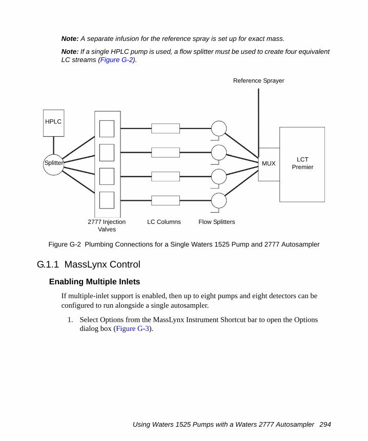
Note: A separate infusion for the reference spray is set up for exact mass.
Note: If a single HPLC pump is used, a flow splitter must be used to create four equivalent LC streams (Figure G-2).
Figure G-2 Plumbing Connections for a Single Waters 1525 Pump and 2777 Autosampler
G.1.1 MassLynx Control
Enabling Multiple InletsIf multiple-inlet support is enabled, then up to eight pumps and eight detectors can be configured to run alongside a single autosampler.
1. Select Options from the MassLynx Instrument Shortcut bar to open the Options dialog box (Figure G-3).
Splitter
Splitter
LC Columns
LCTPremier
Flow Splitters
HPLC
MUX
2777 Injection Valves
Reference Sprayer
Using Waters 1525 Pumps with a Waters 2777 Autosampler 294

Figure G-3 Options Dialog Box
2. Select Multi-Inlet Capability and the number of Parallel Inlets.
Note: The number of parallel inlets relates to the number of pumps; up to eight Parallel inlets (pumps) can be chosen. To configure the pumps see “Selecting Multiple Inlets” on page 295.
3. Select Allow Random Bottle Locations in Sample List.
Note: This lets the system use non-sequential vial references in a sample list when on a MUX system.
4. Ensure that Multi-probe Capability is selected5. Click OK.
Selecting Multiple Inlets1. Select Inlet Method from the MassLynx Instrument shortcut bar to open the Inlet
Method Editor.2. Select Tools > Instrument Configuration to open the Inlet Configuration window.3. Click Configure to open the Inlet Configuration Wizard (for further details see the
MassLynx Inlet Control Guide).
Using Waters 1525 Pumps with a Waters 2777 Autosampler 295

4. Select the required configuration. Figure G-4 shows four Waters 1525 pumps a Waters 2777 autosampler and four Waters 2488 UV detectors
Figure G-4 Inlet Configuration Window
5. From Inlet Configuration window click Events & Triggering to open the Events and Triggering Wizard. Ensure that the correct contact closure port has been selected.
6. In the Inlet Configuration Window Click Finish.
G.2 Using a Gilson 215/889 Autosampler
The recommended plumbing connections between the Gilson 215/889 Multiprobe autosampler and the 5-Way MUX are shown in (Figure G-5).
Using a Gilson 215/889 Autosampler 296

Figure G-5 Plumbing Connections for Gilson 215/889
The flow from an HPLC pump is connected to the four injection valves using a 4-way splitter. The HPLC pump is then operated at 4 times the flow rate required for an individual column.
Note: A separate infusion for the reference spray is set up for exact mass.
G.2.1 Plumbing a 4 or 8 -Probe Gilson 215/8891. Insert four/eight injection needles on the left hand side of the injector arm.
Note: If using a 4-Probe Gilson 215/889, remove the lines from the splitter to Rheodyne valves 5, 6, 7 and 8 and blank these lines on the splitter.
2. The following schematic diagrams (Figures G-6 and G-7) show the LC connections from the outlets of the Gilson injector port assembly to the source inlets of a 4 or 8-way MUX.
LCTPremier
HPLC
Splitter
GilsonMultiProbe
LC Columns Splitters
MUX
Reference Spray
Using a Gilson 215/889 Autosampler 297

Figure G-6 4 injectors to 4-way MUX
Figure G-7 8 injectors to 8-way MUX
The Gilson Numbering SystemThe Gilson numbering system is reverse to that of the MUX and MassLynx (Figures G-6 and G-7). With the 4-way plumbing, MUX inlets 1 to 4 correspond to well positions 1A to 1D respectively, and subsequently, 1 E to 1H of a 96-well microtitre plate.
MUX Inlets
RheodyneInjectors
Injection Ports
Injection Needles
MUX Inlets
RheodyneInjectors
Injection Ports
Injection Needles
298 MUX Plumbing

For the 8-way plumbing shown, MUX inlets 1 to 8 correspond to well positions 1A to 1H respectively.
CommunicationThe Gilson 215 / 889 Multiprobe is controlled through MassLynx. Connect the serial cable (supplied) from either COM1 or COM2 on the MassLynx PC to the RS232 connection on the Gilson 215 liquid handling unit.
Contact Closure
Connect Contact Closure 1 on the Gilson 215 to one of the contact closure inputs on the MS instrument, and Contact Closure 2 to the LC pump, if required.
G.2.2 MassLynx Control1. Select Inlet Method from the MassLynx Instrument shortcut bar to open the Inlet
Method Editor.2. Select Tools > Instrument Configuration to open the Inlet Configuration window.3. Click Configure to open the Inlet Configuration Wizard (for further details see the
MassLynx Inlet Control Guide).4. Select the desired inlet and the Gilson autosampler.5. From Inlet Configuration window click Events & Triggering to open the Events and
Triggering Wizard. Ensure that the correct contact closure port has been selected.6. In the Inlet Configuration Window Click Finish.7. From the Inlet Method Editor select Gilson Sampler > Advanced Configuration.
Using a Gilson 215/889 Autosampler 299

8. On the hardware page ensure that the ID’s match those on the Gilson hardware (rotary switches on the rear of the 215 and 889 units) (Figure G-8).
Figure G-8 Hardware Page
Figure G-9 Communications Page
300 MUX Plumbing

9. On the Communications page ensure that the Multi-Injector Mode is set to Single Injection and check that the correct COM port is selected (Figure G-9).
10. Click OK.11. Select Autosampler on the Inlet Method Editor shortcut bar. 12. Select Inject Partial Loop from the Task drop-down list and enter the parameters as
shown in Figure G-10.
13. Click to enter it in the Task List window.
Figure G-10 Autosampler Parameters: Inject Partial Loop
14. Select Rinse Injector Port from the Task drop-down list and enter the parameters as shown in Figure G-11.
15. Click to enter it in the Task List window.
Using a Gilson 215/889 Autosampler 301

Figure G-11 Autosampler Parameters: Rinse Injector Port
16. Select Rinse Inside Needle from the Task drop-down list and enter the parameters as shown in Figure G-12.
17. Click to enter it in the Task List window.
302 MUX Plumbing

Figure G-12 Autosampler Parameters: Rinse Inside Needle
18. Select the Dilutor Configuration page (Figure G-13) and confirm that the parameters match the hardware.
Figure G-13 Autosampler Parameters: Dilutor Configuration
Using a Gilson 215/889 Autosampler 303

19. Select the Sample Configuration page and confirm that the bed layout parameters match the bed layout of the sample racks on the autosampler.
304 MUX Plumbing

Index
Aacquiring dataanalog 92Sample List 61Tune window 36
acquisitionmonitoring 37
ACQUITY 31activated alumna
replacing 164actual mass 66adding
functions 90tasks 259
air filters 159air filters, changing 159analog data
acquiring 92Analog Data dialog box 93APCI 2APCI corona discharge pin 112, 290APCI in dual mode 291APCI mode 290APCI probe 102, 107, 108, 113, 289, 290
heaterreplacing 216
stainless steel capillary, replacing 205tip, cleaning 190
APPI 3APPI connector 105APPI drive cable 105APPI in dual mode 291APPI lamp
drive assembly 102
drive assembly mounting shaft numbered indexing indents 103
maintaining 219replacing bulb 219
APPI mode 106, 289obtaining an ion beam 107preparing for operation in 106
APPI source enclosure side plate 103APPI Source tab 108APPI/APCI source tab 113assembling
source ion block 186Atlantis dC18 column 287Atmospheric Pressure Chemical Ionization,
see APCIAtmospheric Pressure photoionization, see
APPIAuto Control Tasks 85Auto Control Tasks page 258automatic shutdown 83
Bbaffle, removing 171biological hazards viibulb, replacing 219
Ccables
drive 105HT 106
calculatingmass accuracy 65
calibration solution 56Capillary connection 9, 12
Index 305

Capillary connector 106Centroid data 90Centroid Threshold 46Centroiding Parameters 46changing
air filters 159rotary pump oil 164
changing the source configuration 14Checking the Resolution 39chemical hazard viichemical noise 248Chromatogram Real-Time update 37chromatographic signal to noise 287cleaning
APCI probe tip 190cone gas cone 182corona discharge pin 189ESI probe tip 188extraction cone 185ion block 185isolation valve stem 185sample cone 182source ion guide assembly 184
cleaning the oscillating baffleLockSpray 221
cleaning the UV lamp window 220COM1 connection 23Combine 39combined APPI/APCI source, installing 105complete shutdown 252conditioning the MCP 187cone gas cone, cleaning 182Cone Ramp dialog box 271Configure Contact Closures 257configure GPIB 80Configure Shutdown on Error 255connecting power 19connections
gas 20
connectorAPPI 105Capillary 106
contact closures 22contacting Waters 249Continuum data 90controlling
gas flows 270syringe pump 270
controlsInject switch 11Load switch 11
Conventions, documentation xixcooling fans 159copying
functions 91corona discharge pin 106
APCI 112, 290cleaning 189dual APPI/APCI 112, 291installing 96replacing 189
creatingparameter files 273
Ddata
Centroid 90Continuum 90MCA 90
data system 6Data Threshold 47DDTC see Digital Deadtime Correction 57Deadtime Correction 57deleting
functions 91tasks 260
Desolvation gas connection 9
306 Index

desolvation gas heaterMUX 151
Desolvation Heater connection 9dialog boxes
Analog Data 93Cone Ramp 271Configure Event In 257Dynamic Range Enhancement 70Options 152Readbacks 272Shutdown on Error Configuration 256Solvent Delay 92Syringe Selection 270Tuning Setup 271
dialog boxessGas Threshold 258
Digital Deadtime Correction wizard 57disassembling
source ion block 177divert/injection valve 10Documentation
conventions xixDRE
Magnification Factor 70Sample List 78setting the reference compound 74settings 69Stitch Window 70wizard 70
dual APPI/APCI corona discharge pin 112, 291
dual APPI/APCI mode 111, 290APCI in 291APPI in 291creating an MS method file 119obtaining an ion beam 113preparing for operation in 111
DXC Temperature Compensation 47Dynamic Range Enhancement see DRE
I
EE1M18 pump 6, 162E2M28 pump 5, 162
gas-ballasting 162editing
tasks 259Edwards
E1M18 pump 6E2M28 pump 5
electrical connectionsCOM 1 23
electronic noise 248electronics maintenance 159Electronics switchl 17ElectroSpray ionization, see ESIembedded PC 6Embedded PC Reset 244emergency shutdown 252end flange
MUX 148endoscope 126Error
Shutdown 255ESCi 116ESCi mode
creating an MS method file 119obtaining an ion beam 117
ESI 2ESI probe
removing 95stainless steel capillary, replacing 195tip
cleaning 188replacing 188
Exhausts 21extraction cone, cleaning 185
Index 307

Ffault finding 243
LockSpray 248fitting
ion block 186ion source enclosure 186
foreline trap 164front cover connections 8front panel 7function list
adding a new function 90changing the order of functions 91copying a function 91modifying a function 90opening a saved list
openingfunction list 94
removing a function 91saving 93setting a solvent delay 92setting the maximum retention time 91
function listssetting up 87
Ggas connections 20Gas Fail 22gas flows, controlling 270Gas Thresholds 257gas-ballasting
E2M28 162maintenance 161
Glass Capillary Option 139graphite ferrule
MUX 240
Hhazards viihigh backpressure 246high noise levels 247HPLC pump 107, 113, 117HT cable 106
Iindicated mass 66infusing leucine enkephalin
positive mode 29W positive mode 32
infusing raffinoseV negative mode 33W negative mode 34
Inject switch 11Inlet Method Editor 78inserting
tasks 259installation
NanoLockSpray 124installing
corona discharge pin 96MUX 148
installing combined APPI/APCI source 105installing the electrospray probe 25instrument covers
front panel 7rear panel 17removing 8top panel 23
instrument front panel connectorsAPPI 105Capillary 106
instrument name, selectingselecting
instrument name 277
308 Index
instrument parameter files 273creating new 273opening 274
instrument source enclosure 103intended use viiinter scan delay, selecting 271Inter-Scan Delay 89ion beam
obtaining in APPI mode 107obtaining in dual APPI/APCI mode 113obtaining in ESCi mode 117
ion blockcartridge heater, replacing 191cleaning 185fitting 186removing 173
Ion Guide Transfer Optics 4Ion Mode menu 270ion optics 3
V mode 4W mode 4
ion source enclosurefitting 186removing 173
ionization mode, selecting 270ionization techniques
APCI 2APPI 3ESI 2
isolating from mains 18isolation valve
stem, cleaning 185isotope distributions, incorrect 247
Llamp
cleaning window 220replacing bulb 219
I
turning on 103LC Inlet
setting up 78LED display 15LED pump-down sequence 16LED vent sequence 16Load switch 11LockSpray 61LockSpray maintenance 221Log Parameters 262loss of sensitivity 247Lteff 41, 47
MMagnification Factor 70
setting 70mains power socket 18mains power unit 17maintenance
air filters 159cooling fans 159foreline trap 164gas-ballasting 161handling 158LockSpray 221MUX 231NanoLockSpray 226safety 158source 169vacuum system 161
maintenance schedule 157mass accuracy
calculating 65nominal 41
mass calibration accuracyperformance specification 284
mass measurement accuracyperformance specification 286
Index 309

mass range 35MassLynx
Instrument shortcut bar 153MS Tune icon 153opening 26Tune window 153
ES+ Source tab 154MassLynx software 7MassLynx Tune window
APPI Source tab 108MassLynx Tune window, opening 269maximum retention time 91MCA data 90MCP conditioning 187MCP setup wizard 47Minimum Points 46minimum scan times 89modes
V negative 33V positive 29W negative 34W positive 32
modifyingfunctions 90tasks 259
modular LockSpray source 12monitoring the acquisition 37MS Function Editor 119MS Method Editor 87, 119MS method file, creating for dual APPI/APCI
mode 119MS method file, creating for ESCi mode 119MS Scan Function 87MUX
desolvation gas heater 151end flange 148graphite ferrule 240installing 148interface 145
maintenance 231operating conditions 152operation 152replacing probe tips 235replacing sample capillary 237tuning 152
MUX flangeinserting 149removing 233
MUX-technology see MUX
Nnano reference probe assembly 126Nanoflow connection 11NanoFlow options 138Nano-LC Assembly 142Nano-LC Option 141, 143NanoLockSpray
data processing 137overview 123Tuning 136
NanoLockSpray maintenance 226nanovial tip position 139Nebuliser connection 12Nebuliser gas connection 9no beam 245noise levels
chemical 248electronic 248
nominal mass measurement 41Nominal Mass Wizard 43NP Multiplier 46, 60
Oobtaining a mass spectrum 29opening 269
MassLynx 26
310 Index
parameter files 274Peak Display window 275
operate LED display 15operating conditions 152Operation
Nanoflow 143operation
MUX 152Options dialog box 152overnight shutdown 252
Pparameters
Centroid Threshold 46Data Threshold 47Minimum Points 46NP Multiplier 46resolution 46
PC Link 23Peak Display menu 275peak display, customizing
colors 276display grid 277intensity display 277numbers 276trace line appearance 276
peakschanging gain 275selecting
span 274Performance Specifications 283, 289Performing a DRE Experiment 75pin, corona discharge 106
APCI 112, 290dual APPI/APCI 112, 291
Pinging the EPC 243Plug parking 10power off, reboot 245
I
power unit 17ppm error 66primary interface panel 9printing
tune information 274probe
removing 170probe, APCI 102, 107, 108, 113, 289, 290pump
HPLC 107, 113, 117syringe 107, 113, 117
pump control socket 18pump switching box 18pump-down sequence
LED 16pumps
Edwards E1M18 6Edwards E2M28 5switching box 18turbomolecular 5
pusher settings 35
RReadbacks dialog box 272Real-Time update
Chromatogram 37Spectrum 38
rear interface panel 21rear panel 17reassembling the refernce probe 223reboot
EPC 244power off 245TELNET 244
recirculationrotary pump oil 161
reference probereassembling 223
Index 311

reference probe capillaryLockSpray 221NanoLockSpray 227
reference probe tips 226removing
baffle 171ESI probe 95instrument covers 8ion block 173ion source enclosure 173sample cone 170source ion guide 174steel capillary 222
repeller electrode 102, 289replacing
APCI probe heater 216APCI probe stainless steel capillary 205corona discharge pin 189ESI probe stainless steel capillary 195ESI probe tip 188ion block cartridge heater 191reference probe capillary, LockSpray
221reference probe
capillary,NanoLockSpray 227replacing activated alumna 164Resolution 60resolution
calculation 39checking 39parameter 46
resolution in negative ion 283resolution in positive ion 283Rheodyne injection valve 10ringing artefacts 68RMS error 285, 286rotary pump
checking oil 164rotary pump oil
changing 164recirculation 161
running Startup and Shutdown files 261
Ssafety and handling 158sample capillary
replacingMUX 237
sample cone 108, 112cleaning 182fitting to instrument 187removing 170
Sample Listacquisition 61DRE 78
sample syringe 155sampling rotor assembly
cleaning 231cleaning components 235disassembling 234reassembling 235
savinga function list 93
saving tune parameters 273Scan Time 89scan time, selecting 271Scans To Average
parametersScans To Average 138
secondary interface panel 11sensitivity
decrease 247sensitivity in negative ion 284sensitivity in positive ion 284setting
the Magnification Factor 70setting a solvent delay 92
312 Index

setting upfunction lists 87syringe pump 267
settingsDRE 69TDC 45
shutdowncomplete 252emergency 252overnight 252
Shutdown Editor 84, 253toolbar 254
Shutdown Log 261Shutdown page 254shutting down
for day 83single point lock mass 61sockets
mains power 18pump control 18
sodium formate solution 57software
MassLynx 7software upgrade CD-ROM 105Solvent Delay dialog box 92source configuration
changing 14source enclosure 103source ion block
assembling 186disassembling 177
source ion guideremoving 174
source ion guide assemblycleaning 184
source, cleaning 169source, installing the combined APPI/APCI
105Spectrum Real-Time update 38
I
starting the instrument 251status display 15steel capillary 222Stitch Window 70switches
electronics 17Inject 11Load 11system 17
syringe pump 107, 113, 117controlling 270setting up 267
Syringe Selection dialog box 270syringe type, selecting 270System switch 17
TTDC Settings 46TDC settings 45TELNET, reboot 244toolbars
Shutdown Editor 254top panel 23triggering method 82tune information, printing 274tune parameters
changing 273saving 273
Tune window 28, 99, 153, 269APPI Source tab 108Diagnostics tab 282ES+ Source tab 154opening 269
Tune window acquisition 36tuning
MUX 152Tuning Setup dialog box 271turbomolecular pump 5
Index 313

Uunsteady beam 245UPLC 31use
intended viiUV lamp 102
cleaning window 220replacing bulb 219turning on 103
VV mode 4V negative mode 33V positive mode 29vacuum LED display 15vacuum system 5
maintenance 161Veff 47vent sequence
LED 16
WW mode 4W negative mode 34W positive mode 32Waters Atlantis dC18 column 287Waters, contacting 249wizards
Digital Deadtime Correction 57DRE 70Events Configuration 81Inlet Configuration 80MCP setup 47nomimal mass 41
wizards Nominal Mass 43workstation 6
ZZ-focusing lens 67ZSpray source 290
314 Index